US9167137B2 - Security camera having a cable assembly with an integrated processing module - Google Patents
Security camera having a cable assembly with an integrated processing moduleDownload PDFInfo
- Publication number
- US9167137B2 US9167137B2US13/874,279US201313874279AUS9167137B2US 9167137 B2US9167137 B2US 9167137B2US 201313874279 AUS201313874279 AUS 201313874279AUS 9167137 B2US9167137 B2US 9167137B2
- Authority
- US
- United States
- Prior art keywords
- camera head
- camera
- processing module
- image processing
- cable
- Prior art date
- Legal status (The legal status is an assumption and is not a legal conclusion. Google has not performed a legal analysis and makes no representation as to the accuracy of the status listed.)
- Active, expires
Links
Images


Classifications
- H04N5/2251—
- H—ELECTRICITY
- H04—ELECTRIC COMMUNICATION TECHNIQUE
- H04N—PICTORIAL COMMUNICATION, e.g. TELEVISION
- H04N23/00—Cameras or camera modules comprising electronic image sensors; Control thereof
- H04N23/50—Constructional details
- G—PHYSICS
- G08—SIGNALLING
- G08B—SIGNALLING OR CALLING SYSTEMS; ORDER TELEGRAPHS; ALARM SYSTEMS
- G08B13/00—Burglar, theft or intruder alarms
- G08B13/18—Actuation by interference with heat, light, or radiation of shorter wavelength; Actuation by intruding sources of heat, light, or radiation of shorter wavelength
- G08B13/189—Actuation by interference with heat, light, or radiation of shorter wavelength; Actuation by intruding sources of heat, light, or radiation of shorter wavelength using passive radiation detection systems
- G08B13/194—Actuation by interference with heat, light, or radiation of shorter wavelength; Actuation by intruding sources of heat, light, or radiation of shorter wavelength using passive radiation detection systems using image scanning and comparing systems
- G08B13/196—Actuation by interference with heat, light, or radiation of shorter wavelength; Actuation by intruding sources of heat, light, or radiation of shorter wavelength using passive radiation detection systems using image scanning and comparing systems using television cameras
- G08B13/19617—Surveillance camera constructional details
- G08B13/19619—Details of casing
- H—ELECTRICITY
- H04—ELECTRIC COMMUNICATION TECHNIQUE
- H04N—PICTORIAL COMMUNICATION, e.g. TELEVISION
- H04N7/00—Television systems
- H04N7/18—Closed-circuit television [CCTV] systems, i.e. systems in which the video signal is not broadcast
Definitions
- the present disclosureis directed at a security camera having a cable assembly with an integrated processing module. More particularly, the present disclosure is directed at a security camera having a camera head and a cable assembly with an integrated processing module that is sized to fit through an aperture that can be covered by the camera head.
- One application of security camerasis to conduct surreptitious surveillance.
- a security cameratypically needs to remain hidden from the people on whom the surveillance is being conducted.
- Miniaturizing a camerais one way to help it remain hidden; the smaller the camera, the more locations in which the camera may be placed to conduct the surveillance and the harder it is for the camera to be discovered.
- a continued focus of the security industryis accordingly miniaturizing security cameras in a manner that is not detrimental to ease of use or installation.
- a security camerathat comprises a camera head and a cable assembly.
- the camera headcomprises a lens and an image sensor
- the cable assemblycomprises a cable connected to the camera head and a processing module connected to the camera head via the cable.
- the processing modulecomprises image processing circuitry communicative with the image sensor and power circuitry electrically coupled to the image processing circuitry and the camera head.
- the processing moduleis sized to fit through an aperture in a mounting surface that can be covered by the camera head when the camera head is mounted to the mounting surface.
- the cable assemblymay be sufficiently light to be supportable indefinitely solely by the camera head when the cable assembly is dangling from the camera head.
- the connection between one or both of i) the cable and the camera head and ii) the cable and the processing modulemay be reinforced such that the camera head is able to support the cable assembly.
- the image processing circuitrymay comprise an image processing printed circuit board (PCB) and the power circuitry may comprise a power PCB, wherein both of the PCBs may be housed within the processing module.
- PCBimage processing printed circuit board
- the PCBsmay be opposite each other. Alternatively or additionally, the PCBs may be parallel to each other. Additionally or alternatively, they may have identical dimensions.
- the image processing circuitrymay comprise a processor and the heat spreader may be attached to the processor.
- the heat spreadermay comprise a planar member extending longitudinally along the processing module and over the image processing PCB, and two wing members connected to opposite edges of the planar member and extending past the side edges of the image processing PCB.
- the wing membersmay terminate in a space between the image processing and power PCBs.
- the cablemay comprise a jacketed micro-coaxial cable having multiple conductors.
- the camera headmay consists essentially of the lens and image sensor.
- a security camerathat comprises a camera head and a cable assembly.
- the camera headcomprises a lens and an image sensor.
- the cable assemblycomprises a cable connected to the camera head and a processing module connected to the camera head via the cable.
- the processing modulecomprises image processing circuitry communicative with the image sensor and comprising an image processing printed circuit board (PCB), an power circuitry electrically coupled to the image processing circuitry and the camera head and comprising a power PCB.
- the image processing PCB and power PCBare positioned parallel to and opposite each other and the processing module is sized to fit through an aperture in a mounting surface that can be covered by the camera head when the camera head is mounted to the mounting surface.
- the cable assemblyis sufficiently light to be supportable indefinitely solely by the camera head when the cable assembly is dangling from the camera head.
- the connection between one or both of i) the cable and the camera head and ii) the cable and the processing modulemay be reinforced such that the camera head is able to support the cable assembly.
- the image processing circuitrymay comprise a processor laid out on the image processing PCB and the processing module may further comprise a heat spreader attached to the processor.
- a method for mounting a security cameracomprising a camera head and a cable assembly.
- the methodcomprises drilling an aperture in a mounting surface, wherein the aperture is sized to allow the cable assembly to pass through it and to be coverable by the camera head when the camera head is secured to the mounting surface; connecting the camera to a network via the cable assembly; inserting the cable assembly through the aperture, and securing the camera head to the mounting surface such that the camera head covers the aperture.
- the cable assemblycomprises a cable connected to the camera head and a processing module connected to the camera head via the cable.
- the cable assemblymay be sufficiently light to be supportable indefinitely solely by the camera head when the cable assembly is dangling from the camera head.
- the processing modulemay comprise image processing circuitry communicative with the image sensor, wherein the image processing circuitry comprises an image processing printed circuit board (PCB); and power circuitry electrically coupled to the image processing circuitry and the camera head, wherein the power circuitry comprises a power PCB and wherein both of the PCBs are housed within the processing module.
- image processing circuitrycommunicative with the image sensor
- the image processing circuitrycomprises an image processing printed circuit board (PCB)
- PCBprinted circuit board
- the PCBsmay be opposite each other. Additionally or alternatively, they may be parallel to each other. Additionally or alternatively, they may have identical dimensions.
- the processing modulemay further comprise a heat spreader attached to the image processing circuitry.
- the image processing circuitrymay comprise a processor and the heat spreader may be attached to the processor.
- the cablemay comprise a jacketed micro-coaxial cable having multiple conductors.
- FIGS. 1( a )-( g )are perspective, front elevation, rear elevation, right side elevation, left side elevation, top plan, and bottom plan views, respectively, of a security camera having a camera head and a cable assembly, according to one embodiment.
- FIG. 2is a right side elevation view of the security camera with a dome cover of the camera head removed.
- FIG. 3is a right side elevation view of the security camera with the dome cover of the camera head removed and a rear shell of an eyeball camera, which forms part of the camera head, also removed.
- FIGS. 4( a )-( e )are right side elevation, left side elevation, top plan, bottom plan, and perspective views, respectively, of a processing module of the security camera, with the processing module's module housing removed.
- FIG. 5is a perspective view of the processing module of FIGS. 4( a )-( e ) without its module housing and without a heat spreader.
- FIG. 6is a block diagram of the security camera.
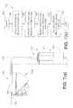
- FIG. 7( a )is a side sectional view of a mounting surface showing the security camera installed on to the mounting surface.
- FIG. 7( b )is a flowchart depicting a method for mounting the security camera to the mounting surface, according to another embodiment.
- the security industryhas attempted to miniaturize cameras in several ways.
- One wayis by separating the electro-optics in a camera from the image processing circuitry in the camera. This allows the image processing circuitry, which can be relatively bulky, to be located remotely from the electro-optics, which typically comprise a relatively small lens and image sensor.
- the image processing circuitryis contained within a processing module and the electro-optics are contained within a camera head spaced from the processing module.
- the camera headwhich is the portion of the camera visible to surveillance subjects, can accordingly be manufactured smaller than if the electro-optics and image processing circuitry were both contained within the camera head.
- a cableconnects the processing module and the camera head, and the camera is connected to a network via the processing module. In the case of an Internet protocol (IP) camera, the camera is connected to an IP network.
- IPInternet protocol
- a conventional processing moduleis large enough that the technician mounts both the camera head and the processing module to one or more mounting surfaces because the processing module is too large and heavy to be left dangling from the camera head following installation or to fit through a hole that can subsequently be covered by the camera head. The technician therefore cannot install the camera having a distinct processing module and camera head in the same way as he or she can install an integrated camera in which all electronics and optical equipment are contained within the camera head.
- the techniciansimply needs to mount the camera head to a mounting surface and connect the camera head to the network; if the camera is an IP camera, the network is frequently used to power the camera as well as for communication.
- the technicianidentifies a concealed location in which to mount the processing module, separately mounts the processing module and camera head, connects the camera head to the processing module, and then connects the processing module to the IP network.
- the present disclosureis directed at embodiments of a security camera that comprise a distinct processing module and camera head connected by a cable, but in which the processing module is small and light enough that the technician does not need to mount both the processing module and the camera head when mounting the camera.
- the techniciansimply drills an aperture, connects the processing module to the network, inserts the processing module through the aperture, and then covers the aperture using the camera head by mounting the camera head to the mounting surface and over the aperture.
- the processing moduleis light enough to dangle freely from the camera head by the cable that connects the two.
- the processing moduleis effectively transparent to the technician, since he or she can simply connect the camera to the network and mount the camera head to the mounting surface, analogous to what he or she would do when installing a camera in which all electronics and optics are contained within the camera head. While the depicted camera is an IP camera, alternative embodiments (not depicted) include non-IP cameras, such as analog cameras, as well.
- FIGS. 1( a )-( g )there are shown perspective, front elevation, rear elevation, right side elevation, left side elevation, top plan, and bottom plan views, respectively, of a security camera 100 having a camera head 104 and a cable assembly 102 , according to one embodiment.
- the cable assembly 102includes a processing module 103 and a cable 106 that connects the processing module 103 and the camera head 104 .
- the camera 100 depicted hereinis a dome camera; however, in alternative embodiments (not depicted), the camera 100 may be another type of camera, such as a box camera, pinhole camera, or bullet camera.
- the camera head 104comprises a dome base 124 on which is attached a dome cover 108 .
- An opening in the dome cover 108 and base 124allows an eyeball camera 110 , which rests on the base 124 , to protrude out the front of the dome cover 108 .
- At the front of the eyeball camera 110is the camera 100 's lens 112 .
- the lens 112focuses light on to an image sensor 126 (shown in FIG. 3 ) mounted within the eyeball camera 110 .
- a micro-coaxial cable 106connects the eyeball camera 110 to the processing module 103 , which processes the video signal that the image sensor 126 outputs.
- FIGS. 1( a )-( g )only the exterior of the processing module 103 is visible.
- the top, bottom, left, and right sides of the processing module 103are defined by a module housing 114 , while front and rear end plates 115 cap the ends of the processing module 103 .
- the micro-coaxial cable 106is connected to the processing module 103 's rear end plate 115 .
- a waterproof grommet 122circumscribes the end of the micro-coaxial cable 106 that terminates at the processing module 103 and is screwed into the rear end plate 115 to ensure a water tight seal.
- the processing module 103 's front end plate 115has a network jack in the form of an RJ45 (Ethernet) jack 118 to receive an RJ45 plug that connects the camera 100 to the IP network.
- RJ45Error-Fi Protected Group
- PoEpower over Ethernet
- a pair of LEDs 120 indicating connection and link status and a memory card slot 116are also present on the front end plate 115 .
- FIGS. 2 and 3there are shown right side elevation views of the camera 100 . More specifically, FIG. 2 shows a right side elevation view of the camera 100 with the dome cover 108 removed, while FIG. 3 shows a right side elevation view of the camera with the dome cover 108 removed and with a rear shell of the eyeball camera 110 removed, revealing the circuitry contained within the eyeball camera 110 .
- Inside the eyeball camera 110is a lens mount 128 that is connected to the image sensor 126 .
- the micro-coaxial cable 106is electrically coupled to the image sensor 126 via an I-PEX 20373-series connector, which is also used to couple the micro-coaxial cable 106 to the processing module 103 .
- the image sensoris an AptinaTM AR0330 sensor that outputs a high-speed serial data stream along the micro-coaxial cable 106 using the MIPI® protocol.
- the micro-coaxial cable 106is jacketed with thermoplastic polyurethane and includes fourteen conductors to facilitate high-speed serial communication.
- the micro-coaxial cable 106may be manufactured using a different number of conductors or a different jacket material so long as communication between the processing module 103 and camera head 104 can be performed sufficiently quickly to transfer the video signal that the image sensor 126 outputs.
- FIG. 6shows a block diagram of the camera 100 .
- the lens 112 and image sensor 126are shown as being located within the camera head 104 .
- the processing module 103includes a system on a chip (SoC) 136 that comprises a processor 138 , an image signal processor (ISP) 127 , a Media Access Controller (MAC) 144 , and an I 2 C interface 142 .
- SoCsystem on a chip
- the processor 138is communicative with each of the ISP 127 , MAC 144 , and I 2 C interface 142 .
- FIG. 6illustrates the three different ways the processing module 103 is electrically coupled to the camera head 104 .
- the ISP 127is communicative with the image sensor 126 via the MIPI® protocol; two, the I 2 C interface 142 is communicative with the image sensor 126 using the I 2 C protocol; and three, the camera head 104 is powered with a 3.3 V power supply line from the processing module 103 . These three forms of electrical coupling take place via the micro-coaxial cable 106 .
- the I 2 C interface 142is used to control camera parameters such as gain, exposure, and frame rate.
- the SoC 136comprises part of the camera 100 's image processing circuitry, which comprises part of and is laid out on an image processing printed circuit board (PCB) 130 .
- PCBprinted circuit board
- PHYphysical layer integrated circuit
- flash memory 148which is an exemplary non-transitory computer readable medium that is non-volatile and that stores statements and instructions to cause the SoC 136 to perform tasks such as image processing
- RAM 150which is another exemplary non-transitory computer readable medium, but which is volatile and which the SoC 136 uses to temporarily store information and for working space while performing tasks.
- power circuitrywhich comprises part of and is laid out on a power PCB 132 .
- the power PCB 132On the power PCB 132 is the RJ45 jack 118 ; Ethernet magnetics 152 , which are communicative with the RJ45 jack 118 and the PHY 146 ; and a DC to DC converter 154 , electrically coupled to the Ethernet magnetics 152 , that outputs a 3.3 V signal to power the image processing circuitry and the camera head 104 .
- the camera 100is powered using PoE technology, although in alternative embodiments (not depicted) the camera 100 may be powered using, for example, an AC adapter or with batteries.
- the processing module 103Separating the power circuitry from the image processing circuitry by placing them on their own PCBs 130 , 132 permits the dimensions of the processing module 103 to be relatively small; for example, the depicted processing module 103 is approximately 24 mm (0.94 inches) ⁇ 28 mm (1.1 inches) ⁇ 57 mm (2.2 inches). If all the image processing and power circuitry were on the same PCB, the processing module 103 would be approximately twice as wide or long.
- the processing module 103is designed to operate within the maximum recommend operating temperatures of all circuit components, and in particular the SoC 136 , while operating at an ambient temperature of 50° C.
- the SoC 136 on the image processing PCB 130and to a lesser degree the DC to DC converter 154 on the power PCB 132 , generate relatively large amounts of heat compared to the other circuit components on the PCBs 130 , 132 during operation. Keeping them on separate PCBs 130 , 132 helps to spread the heat throughout the processing module 103 and helps keep the processing module 103 at an acceptable operating temperature.
- FIGS. 4( a )-( e )are right side elevation, left side elevation, top plan, bottom plan, and perspective views, respectively, of the processing module 103 without the module housing 114 .
- These figuresshow a particular manner in which the PCBs 130 , 132 are separated; that is, they are spaced opposite and parallel each other.
- the PCBs 130 , 132are identically sized and the planar surfaces of each of the PCBs 130 , 132 are placed opposite each other such that a line extending perpendicularly from the planar surface of one of the PCBs 130 , 132 perpendicularly intersects the planar surface of the other of the PCBs 130 , 132 .
- the depicted processing module 103shows the PCBs 130 , 132 spaced opposite and parallel each other and the two PCBs 130 , 132 as identically sized
- the PCBs 130 , 132may be one or both of arranged and sized differently.
- the PCBs 130 , 132may be spaced non-parallel to each other; they may have different dimensions or surface areas; or they may not entirely overlap.
- FIGS. 4( a )-( e )also show how the processing module 103 incorporates a heat spreader 134 to increase heat dissipation.
- the heat spreader 134is affixed to the top of the SoC 136 , which is adjacent the underside of the top of the module housing 114 .
- the heat spreader 134comprises a planar member 135 extending longitudinally along the processing module 103 and over the top of the image processing PCB 130 , and two wing members 137 connected to opposite edges of the planar member 135 and extending downwards past the left and right side edges of the image processing PCB 130 .
- the wing members 137terminate in the space between the two PCBs 130 , 132 .
- FIGS. 4( a )-( e )are curved; however, in alternative embodiments (not depicted), the wing members 137 may be planar. Similarly, in alternative embodiments (not depicted) the planar member 135 may be replaced with a non-planar member.
- FIGS. 7( a ) and ( b )there are respectively shown a side sectional view of a mounting surface 160 showing the camera 100 installed on to the mounting surface 160 and a flowchart depicting an exemplary method 700 for mounting the security camera to the mounting surface 160 .
- the technicianbegins the method 700 (block 702 ) and drills an aperture 160 into the mounting surface (block 704 ).
- the aperture 160is sized to allow the cable assembly 102 to pass through it and to be able to be covered by the dome base 124 .
- the technicianthen connects the processor module 103 to the network (block 706 ); in FIG.
- the RJ45 plugis jacketed in a boot 158 , which is visible on the exterior of the processing module 103 .
- connecting the camera 100 to the networkalso powers the camera 100 .
- the technicianinserts the processor module 103 , along with the rest of the cable assembly 102 , through the aperture 156 (block 708 ) and then covers the aperture 156 by mounting the camera head 104 on to the mounting surface 160 and over the aperture 156 such that it covers the aperture 156 (block 710 ).
- the mounting processis complete (block 712 ).
- This installation processis substantially similar to the process used to install a conventional dome camera in which all the electronics and optics are contained within the camera head in that only the camera head 104 is mounted. Consequently, the processing module 103 is functionally transparent to the technician and the technician is able to install the depicted miniaturized dome camera 100 without having to separately mount the processing module 103 .
- the processing modulein alternative cameras with relatively bulky and heavy processing modules, while the extra size in the processing module makes heat dissipation much less of a concern it also requires that the processing module be mounted separately from the camera head and makes it impractical to fit the processing module through an aperture that can subsequently be covered by the camera head.
- the mounting surface 160is a portion of a ceiling near the corner of a room, and the processing module 103 hangs down a wall nearby the ceiling.
- the processing module 103's small size makes it relatively light, which permits the processing module 103 to be supportable indefinitely solely by the camera head 104 when the camera 100 is mounted; in the depicted embodiment, the processing module 103 has a weight of approximately 36 g (1.3 ounces), while the total weight of the camera 100 is approximately 75 g (2.6 ounces).
- the grommet 122reinforces the connection between the micro-coaxial cable 106 and the processing module 103 , which facilitates the ability of the processing module 103 to dangle from the camera head 104 .
- connection between the micro-coaxial cable 106 and one or both of the camera head 104 and processing module 103may be reinforced in any one or more of several different ways, such as by increasing the resiliency of the jacketing on the micro-coaxial cable 106 or by increasing the number of fasteners used to secure the micro-coaxial cable 106 to the camera head 104 and processing module 103 .
- the processing module 103may be secured to the mounting surface 160 behind the camera head 104 or to some other surface out of sight of the surveillance subjects; for example, one side of the processing module 103 may have an adhesive on it that secures it in place behind the mounting surface 160 .
- the processing module 103may be too heavy to dangle free indefinitely from the camera head 104 , in which case either the processing module 103 can be affixed to a surface for support or rested on a flat surface during use, such as on the side of the mounting surface 160 opposite to the side on which the camera head 104 is secured.
- the processing module 103would be approximately twice as wide or long.
- the camera head 104would accordingly have to be increased in size in order to cover the aperture 156 that would have to be made to accommodate this larger processing module 103 , which would make the camera head 104 easier for surveillance subjects to discover.
- micro-coaxial cable 106is permanently coupled to the processor module 103 (i.e., it is not designed to be removed from the processor module 103 during normal use of the camera 100 ), in alternative embodiments (not depicted) this may not be the case.
- the micro-coaxial cable 106may be detachably coupled to the processing module 103 using, for example, a plug and socket connection.
- the SoC 136may instead be, for example, a microprocessor, microcontroller, programmable logic controller, field programmable gate array, or an application-specific integrated circuit.
- Examples of computer readable mediaare non-transitory and include disc-based media such as CD-ROMs and DVDs, magnetic media such as hard drives and other forms of magnetic disk storage, and semiconductor based media such as flash media, random access memory, and read only memory.
- FIG. 7( b )is a flowchart of an exemplary method. Some of the blocks illustrated in the flowchart may be performed in an order other than that which is described. Also, it should be appreciated that not all of the blocks described in the flow chart are required to be performed, that additional blocks may be added, and that some of the illustrated blocks may be substituted with other blocks.
Landscapes
- Engineering & Computer Science (AREA)
- Multimedia (AREA)
- Signal Processing (AREA)
- Physics & Mathematics (AREA)
- General Physics & Mathematics (AREA)
- Studio Devices (AREA)
Abstract
Description
Claims (20)
Priority Applications (6)
| Application Number | Priority Date | Filing Date | Title |
|---|---|---|---|
| US13/874,279US9167137B2 (en) | 2013-04-30 | 2013-04-30 | Security camera having a cable assembly with an integrated processing module |
| US29/470,181USD726799S1 (en) | 2013-04-30 | 2013-10-17 | Miniature dome camera |
| US29/470,179USD726798S1 (en) | 2013-04-30 | 2013-10-17 | Miniature dome camera |
| US29/488,369USD752128S1 (en) | 2013-04-30 | 2014-04-17 | Security camera processor |
| US29/488,371USD719208S1 (en) | 2013-04-30 | 2014-04-17 | Enclosure for a spherical camera |
| US29/488,370USD723604S1 (en) | 2013-04-30 | 2014-04-17 | Spherical security camera |
Applications Claiming Priority (1)
| Application Number | Priority Date | Filing Date | Title |
|---|---|---|---|
| US13/874,279US9167137B2 (en) | 2013-04-30 | 2013-04-30 | Security camera having a cable assembly with an integrated processing module |
Related Child Applications (5)
| Application Number | Title | Priority Date | Filing Date |
|---|---|---|---|
| US29/470,179Continuation-In-PartUSD726798S1 (en) | 2013-04-30 | 2013-10-17 | Miniature dome camera |
| US29/470,181Continuation-In-PartUSD726799S1 (en) | 2013-04-30 | 2013-10-17 | Miniature dome camera |
| US29/488,371Continuation-In-PartUSD719208S1 (en) | 2013-04-30 | 2014-04-17 | Enclosure for a spherical camera |
| US29/488,369DivisionUSD752128S1 (en) | 2013-04-30 | 2014-04-17 | Security camera processor |
| US29/488,370Continuation-In-PartUSD723604S1 (en) | 2013-04-30 | 2014-04-17 | Spherical security camera |
Publications (2)
| Publication Number | Publication Date |
|---|---|
| US20140320646A1 US20140320646A1 (en) | 2014-10-30 |
| US9167137B2true US9167137B2 (en) | 2015-10-20 |
Family
ID=51788937
Family Applications (1)
| Application Number | Title | Priority Date | Filing Date |
|---|---|---|---|
| US13/874,279Active2034-03-24US9167137B2 (en) | 2013-04-30 | 2013-04-30 | Security camera having a cable assembly with an integrated processing module |
Country Status (1)
| Country | Link |
|---|---|
| US (1) | US9167137B2 (en) |
Cited By (4)
| Publication number | Priority date | Publication date | Assignee | Title |
|---|---|---|---|---|
| USD752128S1 (en)* | 2013-04-30 | 2016-03-22 | Avigilon Corporation | Security camera processor |
| US20160127618A1 (en)* | 2014-11-03 | 2016-05-05 | Alarm.Com Incorporated | Fixed View Magnetic Camera |
| US10331019B2 (en) | 2017-06-05 | 2019-06-25 | Avigilon Corporation | Spherical camera |
| US10795242B2 (en) | 2017-06-05 | 2020-10-06 | Avigilon Corporation | Electronics device that dissipates internal device heat via heat sink having exposed surface |
Families Citing this family (7)
| Publication number | Priority date | Publication date | Assignee | Title |
|---|---|---|---|---|
| USD723604S1 (en)* | 2013-04-30 | 2015-03-03 | Avigilon Corporation | Spherical security camera |
| US9167137B2 (en)* | 2013-04-30 | 2015-10-20 | Avigilon Corporation | Security camera having a cable assembly with an integrated processing module |
| US9560535B2 (en)* | 2013-10-03 | 2017-01-31 | Sercomm Corporation | Data stream generation and transmission system and method therefor |
| KR20150110249A (en)* | 2014-03-21 | 2015-10-02 | 타이코에이엠피 주식회사 | Cable assembly, camera module and camera device for vehicle having the same |
| US10592727B2 (en)* | 2014-07-28 | 2020-03-17 | Centre For Development Of Advanced Computing | Apparatus for automated monitoring of facial images and a process therefor |
| JP7023741B2 (en)* | 2018-02-26 | 2022-02-22 | キヤノン株式会社 | Imaging device |
| US10928712B1 (en)* | 2020-08-26 | 2021-02-23 | True North Services Inc. | Self contained covert camera system |
Citations (42)
| Publication number | Priority date | Publication date | Assignee | Title |
|---|---|---|---|---|
| US4746990A (en) | 1985-12-02 | 1988-05-24 | Olympus Optical Co., Ltd. | Detachable unit electronic camera |
| US5418567A (en)* | 1993-01-29 | 1995-05-23 | Bayport Controls, Inc. | Surveillance camera system |
| USD399517S (en) | 1996-12-06 | 1998-10-13 | Elmo Co., Ltd. | Surveillance television camera |
| CA2303525A1 (en) | 2000-03-30 | 2001-09-30 | Silent Witness Enterprises Ltd. | Heat management for enclosed video cameras |
| US6392698B1 (en) | 1996-12-06 | 2002-05-21 | Canon Kabushiki Kaisha | Camera head-detachable image sensing apparatus, image processing apparatus, and image sensing system constituted therewith |
| US6476856B1 (en)* | 1998-03-20 | 2002-11-05 | Westcoast Performance Products Usa, Inc. | Orbit camera housing |
| USD467952S1 (en) | 2002-03-05 | 2002-12-31 | Sony Corporation | Video camera |
| USD473888S1 (en) | 2000-12-14 | 2003-04-29 | Koninklijke Philips Electronics N.V. | Pendant mounted surveillance camera housing |
| USD502196S1 (en) | 2004-02-18 | 2005-02-22 | Sony Corporation | Video camera |
| JP2005157681A (en) | 2003-11-25 | 2005-06-16 | Matsushita Electric Works Ltd | Security sensor |
| USD508934S1 (en) | 2003-06-17 | 2005-08-30 | Ikegami Tsushinki Co., Ltd. | Housing for surveillance camera |
| USD516105S1 (en) | 2004-05-28 | 2006-02-28 | Logitech Europe S.A. | Camera having recessed lens with generally rectangular cutout opening |
| USD536011S1 (en) | 2006-01-20 | 2007-01-30 | Intellectual Solutions, Inc. | System for monitoring an area behind a vehicle |
| USD540360S1 (en) | 2005-07-28 | 2007-04-10 | Matsushita Electric Industrial Co., Ltd. | Surveillance camera |
| USD547347S1 (en) | 2006-01-06 | 2007-07-24 | Samsung Electronics Co., Ltd. | Monitoring camera |
| USD552148S1 (en) | 2006-07-11 | 2007-10-02 | Matsushita Electric Industrial Co., Ltd. | Cover for surveillance camera |
| USD552649S1 (en) | 2006-03-13 | 2007-10-09 | Logitech Europe S.A. | Camera with scroll wheel |
| USD554682S1 (en) | 2005-09-30 | 2007-11-06 | Logitech Europe S.A. | Webcam with a user-configurable shell |
| US20080056709A1 (en) | 2006-09-01 | 2008-03-06 | Protech Optronics Co., Ltd. | Locating structure for eyeball-shaped camera |
| US7345885B2 (en) | 2004-12-22 | 2008-03-18 | Hewlett-Packard Development Company, L.P. | Heat spreader with multiple stacked printed circuit boards |
| US20080136915A1 (en) | 2006-12-06 | 2008-06-12 | Sony Corporation | Wall mount camera |
| US7425101B2 (en) | 2006-05-26 | 2008-09-16 | Yi-Jen Cheng | Image adjusting assembly for a monitoring camera |
| USD614222S1 (en) | 2008-12-05 | 2010-04-20 | Panasonic Corporation | Surveillance camera |
| USD628223S1 (en) | 2009-11-19 | 2010-11-30 | Cheng Uei Precision Industry Co., Ltd. | Webcam |
| USD629439S1 (en) | 2009-11-02 | 2010-12-21 | Panasonic Corporation | Television camera |
| USD633543S1 (en) | 2010-04-13 | 2011-03-01 | Cnb Technology Inc. | Camera for closed circuit television |
| USD633931S1 (en) | 2010-04-13 | 2011-03-08 | Cnb Technology Inc. | Camera for closed circuit television |
| US20110064403A1 (en) | 2009-09-16 | 2011-03-17 | Victor Company Of Japan, Ltd. | Domed-shaped camera |
| US20110123189A1 (en) | 2009-11-20 | 2011-05-26 | Tetsuo Saito | Camera |
| USD648766S1 (en) | 2011-03-11 | 2011-11-15 | Cheng Uei Precision Industry Co., Ltd. | Webcam |
| US20110293264A1 (en)* | 2010-05-31 | 2011-12-01 | Fujitsu Component Limited | Camera module and method for manufacturing camera module |
| US20120008935A1 (en)* | 2010-07-07 | 2012-01-12 | Vivotek Inc. | Photographic device |
| USD653687S1 (en) | 2010-04-02 | 2012-02-07 | Powertech Electronics | Case for security camera |
| USD687085S1 (en) | 2011-10-25 | 2013-07-30 | Kia Rere Innovations Limited | Photographic mount |
| USD690344S1 (en) | 2012-08-29 | 2013-09-24 | Steven J. Hollinger | Housing for a plurality of cameras |
| US20130287385A1 (en) | 2012-04-25 | 2013-10-31 | Axis Ab | Top cover assembly for a monitoring camera |
| USD700232S1 (en) | 2012-11-09 | 2014-02-25 | Bubl Technology Inc. | Spherical imaging system |
| US20140092299A1 (en)* | 2012-09-28 | 2014-04-03 | Digital Ally, Inc. | Portable video and imaging system |
| USD705844S1 (en) | 2012-04-20 | 2014-05-27 | Iconoscope, Llc | Remote camera |
| US8764318B2 (en) | 2010-06-23 | 2014-07-01 | Panasonic Corporation | Dome camera |
| US20140320646A1 (en)* | 2013-04-30 | 2014-10-30 | Avigilon Corporation | Security camera having a cable assembly with an integrated processing module |
| WO2014176659A1 (en) | 2013-04-30 | 2014-11-06 | Avigilon Corporation | Security camera having a cable assembly with an integrated processing module |
- 2013
- 2013-04-30USUS13/874,279patent/US9167137B2/enactiveActive
Patent Citations (42)
| Publication number | Priority date | Publication date | Assignee | Title |
|---|---|---|---|---|
| US4746990A (en) | 1985-12-02 | 1988-05-24 | Olympus Optical Co., Ltd. | Detachable unit electronic camera |
| US5418567A (en)* | 1993-01-29 | 1995-05-23 | Bayport Controls, Inc. | Surveillance camera system |
| USD399517S (en) | 1996-12-06 | 1998-10-13 | Elmo Co., Ltd. | Surveillance television camera |
| US6392698B1 (en) | 1996-12-06 | 2002-05-21 | Canon Kabushiki Kaisha | Camera head-detachable image sensing apparatus, image processing apparatus, and image sensing system constituted therewith |
| US6476856B1 (en)* | 1998-03-20 | 2002-11-05 | Westcoast Performance Products Usa, Inc. | Orbit camera housing |
| CA2303525A1 (en) | 2000-03-30 | 2001-09-30 | Silent Witness Enterprises Ltd. | Heat management for enclosed video cameras |
| USD473888S1 (en) | 2000-12-14 | 2003-04-29 | Koninklijke Philips Electronics N.V. | Pendant mounted surveillance camera housing |
| USD467952S1 (en) | 2002-03-05 | 2002-12-31 | Sony Corporation | Video camera |
| USD508934S1 (en) | 2003-06-17 | 2005-08-30 | Ikegami Tsushinki Co., Ltd. | Housing for surveillance camera |
| JP2005157681A (en) | 2003-11-25 | 2005-06-16 | Matsushita Electric Works Ltd | Security sensor |
| USD502196S1 (en) | 2004-02-18 | 2005-02-22 | Sony Corporation | Video camera |
| USD516105S1 (en) | 2004-05-28 | 2006-02-28 | Logitech Europe S.A. | Camera having recessed lens with generally rectangular cutout opening |
| US7345885B2 (en) | 2004-12-22 | 2008-03-18 | Hewlett-Packard Development Company, L.P. | Heat spreader with multiple stacked printed circuit boards |
| USD540360S1 (en) | 2005-07-28 | 2007-04-10 | Matsushita Electric Industrial Co., Ltd. | Surveillance camera |
| USD554682S1 (en) | 2005-09-30 | 2007-11-06 | Logitech Europe S.A. | Webcam with a user-configurable shell |
| USD547347S1 (en) | 2006-01-06 | 2007-07-24 | Samsung Electronics Co., Ltd. | Monitoring camera |
| USD536011S1 (en) | 2006-01-20 | 2007-01-30 | Intellectual Solutions, Inc. | System for monitoring an area behind a vehicle |
| USD552649S1 (en) | 2006-03-13 | 2007-10-09 | Logitech Europe S.A. | Camera with scroll wheel |
| US7425101B2 (en) | 2006-05-26 | 2008-09-16 | Yi-Jen Cheng | Image adjusting assembly for a monitoring camera |
| USD552148S1 (en) | 2006-07-11 | 2007-10-02 | Matsushita Electric Industrial Co., Ltd. | Cover for surveillance camera |
| US20080056709A1 (en) | 2006-09-01 | 2008-03-06 | Protech Optronics Co., Ltd. | Locating structure for eyeball-shaped camera |
| US20080136915A1 (en) | 2006-12-06 | 2008-06-12 | Sony Corporation | Wall mount camera |
| USD614222S1 (en) | 2008-12-05 | 2010-04-20 | Panasonic Corporation | Surveillance camera |
| US20110064403A1 (en) | 2009-09-16 | 2011-03-17 | Victor Company Of Japan, Ltd. | Domed-shaped camera |
| USD629439S1 (en) | 2009-11-02 | 2010-12-21 | Panasonic Corporation | Television camera |
| USD628223S1 (en) | 2009-11-19 | 2010-11-30 | Cheng Uei Precision Industry Co., Ltd. | Webcam |
| US20110123189A1 (en) | 2009-11-20 | 2011-05-26 | Tetsuo Saito | Camera |
| USD653687S1 (en) | 2010-04-02 | 2012-02-07 | Powertech Electronics | Case for security camera |
| USD633543S1 (en) | 2010-04-13 | 2011-03-01 | Cnb Technology Inc. | Camera for closed circuit television |
| USD633931S1 (en) | 2010-04-13 | 2011-03-08 | Cnb Technology Inc. | Camera for closed circuit television |
| US20110293264A1 (en)* | 2010-05-31 | 2011-12-01 | Fujitsu Component Limited | Camera module and method for manufacturing camera module |
| US8764318B2 (en) | 2010-06-23 | 2014-07-01 | Panasonic Corporation | Dome camera |
| US20120008935A1 (en)* | 2010-07-07 | 2012-01-12 | Vivotek Inc. | Photographic device |
| USD648766S1 (en) | 2011-03-11 | 2011-11-15 | Cheng Uei Precision Industry Co., Ltd. | Webcam |
| USD687085S1 (en) | 2011-10-25 | 2013-07-30 | Kia Rere Innovations Limited | Photographic mount |
| USD705844S1 (en) | 2012-04-20 | 2014-05-27 | Iconoscope, Llc | Remote camera |
| US20130287385A1 (en) | 2012-04-25 | 2013-10-31 | Axis Ab | Top cover assembly for a monitoring camera |
| USD690344S1 (en) | 2012-08-29 | 2013-09-24 | Steven J. Hollinger | Housing for a plurality of cameras |
| US20140092299A1 (en)* | 2012-09-28 | 2014-04-03 | Digital Ally, Inc. | Portable video and imaging system |
| USD700232S1 (en) | 2012-11-09 | 2014-02-25 | Bubl Technology Inc. | Spherical imaging system |
| US20140320646A1 (en)* | 2013-04-30 | 2014-10-30 | Avigilon Corporation | Security camera having a cable assembly with an integrated processing module |
| WO2014176659A1 (en) | 2013-04-30 | 2014-11-06 | Avigilon Corporation | Security camera having a cable assembly with an integrated processing module |
Non-Patent Citations (9)
| Title |
|---|
| Axis Communications, "AXIS P12 Network Camera Series", data sheet; 4 pages. |
| Co-pending U.S. Appl. No. 29/470,179, filed Oct. 17, 2013 and entitled Miniature Dome Camera. |
| Co-pending U.S. Appl. No. 29/470,181, filed Oct. 17, 2013 and entitled Miniature Dome Camera. |
| Co-pending U.S. Appl. No. 29/488,369, filed Apr. 17, 2014 and entitled Security Camera Processor. |
| Co-pending U.S. Appl. No. 29/488,370, filed Apr. 17, 2014 and entitled Spherical Security Camera. |
| Co-pending U.S. Appl. No. 29/488,371, filed Apr. 17, 2014 and entitled Enclosure for a Spherical Camera. |
| International Search Report and Written Opinion dated Nov. 18, 2013, issued by the Canadian Intellectual Property Office in corresponding International Patent Application No. PCT/CA2013/050334, filed Apr. 30, 2013. This application has not yet published. |
| MOBOTIX Corp., S14 FlexMount Camera, instruction manual; 36 pages. |
| MP HD Micro Dome, webpage from URL: http://avigilon.com/products/video-surveillance/cameras/hd-micro-dome/hd-micro-dome-cameras/1-mp-hd-micro-dome. |
Cited By (6)
| Publication number | Priority date | Publication date | Assignee | Title |
|---|---|---|---|---|
| USD752128S1 (en)* | 2013-04-30 | 2016-03-22 | Avigilon Corporation | Security camera processor |
| US20160127618A1 (en)* | 2014-11-03 | 2016-05-05 | Alarm.Com Incorporated | Fixed View Magnetic Camera |
| US9521301B2 (en)* | 2014-11-03 | 2016-12-13 | Alarm.Com Incorporated | Fixed view magnetic camera |
| US10331019B2 (en) | 2017-06-05 | 2019-06-25 | Avigilon Corporation | Spherical camera |
| US10795242B2 (en) | 2017-06-05 | 2020-10-06 | Avigilon Corporation | Electronics device that dissipates internal device heat via heat sink having exposed surface |
| DE112018002841B4 (en) | 2017-06-05 | 2024-07-18 | Motorola Solutions, Inc. | Spherical camera and method for directing IR radiation |
Also Published As
| Publication number | Publication date |
|---|---|
| US20140320646A1 (en) | 2014-10-30 |
Similar Documents
| Publication | Publication Date | Title |
|---|---|---|
| US9167137B2 (en) | Security camera having a cable assembly with an integrated processing module | |
| CN207382417U (en) | Camera Assemblies, Camera Exterior Packages and Outdoor Cameras | |
| BR102015006748B1 (en) | SECURITY CAMERA DEVICE AND METHOD FOR ADJUSTING THE CAMERA LENS POSITION ON A SECURITY CAMERA DEVICE | |
| US10178282B2 (en) | Trail camera with interchangeable hardware modules | |
| TWI804039B (en) | Security camera system with angled cable attachment for increased downward-viewing angle | |
| US20220217273A1 (en) | Spherical camera with magnetic base | |
| EP2992519B1 (en) | Security camera having a cable assembly with an integrated processing module | |
| WO2020000507A1 (en) | Unmanned aerial vehicle and body thereof and pan-tilt-zoom camera | |
| JP7023741B2 (en) | Imaging device | |
| HK1221813B (en) | Security camera having a cable assembly with an integrated processing module | |
| CN204887169U (en) | Versatile network camera with replaceable power modules | |
| KR101532346B1 (en) | Black Box for Vehicle Having Dual Camera | |
| JP2011228768A (en) | Video camera device and heat dissipation structure of the same | |
| CN211685669U (en) | Be applied to shooting subassembly, unmanned aerial vehicle cloud platform and unmanned aerial vehicle of unmanned aerial vehicle cloud platform | |
| US20250107601A1 (en) | Accessorized Laptop Shell Case | |
| CN206712918U (en) | A kind of acoustic image sensing integrating device and elevator | |
| TWM511169U (en) | Multi-functional network camera with replaceable power supply module | |
| TWM516281U (en) | Multichannel web camera with multiple visual angles | |
| HK1226828B (en) | Reader with swappable power/communication module |
Legal Events
| Date | Code | Title | Description |
|---|---|---|---|
| AS | Assignment | Owner name:AVIGILON CORPORATION, CANADA Free format text:ASSIGNMENT OF ASSIGNORS INTEREST;ASSIGNORS:NEUFELD, MICHAEL;MOHAN, SUDEEP;REEL/FRAME:030980/0443 Effective date:20130722 | |
| AS | Assignment | Owner name:HSBC BANK CANADA, CANADA Free format text:SECURITY INTEREST;ASSIGNOR:AVIGILON CORPORATION;REEL/FRAME:035389/0328 Effective date:20150407 | |
| AS | Assignment | Owner name:HSBC BANK CANADA, CANADA Free format text:CORRECTIVE ASSIGNMENT TO CORRECT THE THE GRANT OF SECURITY INTEREST FROM AVIGILON TO HSBC IN APPLICATION NUMBERS 14093397 & 14155197 MUST BE REMOVED. PREVIOUSLY RECORDED ON REEL 035389 FRAME 0328. ASSIGNOR(S) HEREBY CONFIRMS THE THE GRANTOR HAS GRANTED TO THE AGENT A SECURITY INTEREST IN CERTAIN OF THE GRANTOR'S PERSONAL PROPERTY AND FIXTURE ASSETS.;ASSIGNOR:AVIGILON CORPORATION;REEL/FRAME:035613/0705 Effective date:20150407 | |
| STCF | Information on status: patent grant | Free format text:PATENTED CASE | |
| AS | Assignment | Owner name:AVIGILON CORPORATION, CANADA Free format text:RELEASE BY SECURED PARTY;ASSIGNOR:HSBC BANK CANADA;REEL/FRAME:046884/0020 Effective date:20180813 | |
| AS | Assignment | Owner name:AVIGILON CORPORATION, CANADA Free format text:MERGER;ASSIGNORS:MOTOROLA SOLUTIONS CANADA HOLDINGS INC.;AVIGILON CORPORATION;REEL/FRAME:048407/0975 Effective date:20180601 | |
| MAFP | Maintenance fee payment | Free format text:PAYMENT OF MAINTENANCE FEE, 4TH YEAR, LARGE ENTITY (ORIGINAL EVENT CODE: M1551); ENTITY STATUS OF PATENT OWNER: LARGE ENTITY Year of fee payment:4 | |
| AS | Assignment | Owner name:MOTOROLA SOLUTIONS, INC., ILLINOIS Free format text:NUNC PRO TUNC ASSIGNMENT;ASSIGNOR:AVIGILON CORPORATION;REEL/FRAME:061361/0905 Effective date:20220411 | |
| MAFP | Maintenance fee payment | Free format text:PAYMENT OF MAINTENANCE FEE, 8TH YEAR, LARGE ENTITY (ORIGINAL EVENT CODE: M1552); ENTITY STATUS OF PATENT OWNER: LARGE ENTITY Year of fee payment:8 |