US9165449B2 - Occupant egress prediction systems, methods and devices - Google Patents
Occupant egress prediction systems, methods and devicesDownload PDFInfo
- Publication number
- US9165449B2 US9165449B2US13/900,115US201313900115AUS9165449B2US 9165449 B2US9165449 B2US 9165449B2US 201313900115 AUS201313900115 AUS 201313900115AUS 9165449 B2US9165449 B2US 9165449B2
- Authority
- US
- United States
- Prior art keywords
- egress
- person
- support structure
- control system
- contemplated embodiment
- Prior art date
- Legal status (The legal status is an assumption and is not a legal conclusion. Google has not performed a legal analysis and makes no representation as to the accuracy of the status listed.)
- Active, expires
Links
Images


Classifications
- G—PHYSICS
- G08—SIGNALLING
- G08B—SIGNALLING OR CALLING SYSTEMS; ORDER TELEGRAPHS; ALARM SYSTEMS
- G08B21/00—Alarms responsive to a single specified undesired or abnormal condition and not otherwise provided for
- G08B21/02—Alarms for ensuring the safety of persons
- G08B21/04—Alarms for ensuring the safety of persons responsive to non-activity, e.g. of elderly persons
- G08B21/0438—Sensor means for detecting
- G08B21/0461—Sensor means for detecting integrated or attached to an item closely associated with the person but not worn by the person, e.g. chair, walking stick, bed sensor
- A—HUMAN NECESSITIES
- A61—MEDICAL OR VETERINARY SCIENCE; HYGIENE
- A61B—DIAGNOSIS; SURGERY; IDENTIFICATION
- A61B5/00—Measuring for diagnostic purposes; Identification of persons
- A61B5/103—Measuring devices for testing the shape, pattern, colour, size or movement of the body or parts thereof, for diagnostic purposes
- A61B5/11—Measuring movement of the entire body or parts thereof, e.g. head or hand tremor or mobility of a limb
- A61B5/1113—Local tracking of patients, e.g. in a hospital or private home
- A61B5/1115—Monitoring leaving of a patient support, e.g. a bed or a wheelchair
- A—HUMAN NECESSITIES
- A61—MEDICAL OR VETERINARY SCIENCE; HYGIENE
- A61B—DIAGNOSIS; SURGERY; IDENTIFICATION
- A61B5/00—Measuring for diagnostic purposes; Identification of persons
- A61B5/68—Arrangements of detecting, measuring or recording means, e.g. sensors, in relation to patient
- A61B5/6887—Arrangements of detecting, measuring or recording means, e.g. sensors, in relation to patient mounted on external non-worn devices, e.g. non-medical devices
- A61B5/6892—Mats
- A—HUMAN NECESSITIES
- A61—MEDICAL OR VETERINARY SCIENCE; HYGIENE
- A61B—DIAGNOSIS; SURGERY; IDENTIFICATION
- A61B5/00—Measuring for diagnostic purposes; Identification of persons
- A61B5/74—Details of notification to user or communication with user or patient; User input means
- A61B5/746—Alarms related to a physiological condition, e.g. details of setting alarm thresholds or avoiding false alarms
- A—HUMAN NECESSITIES
- A61—MEDICAL OR VETERINARY SCIENCE; HYGIENE
- A61G—TRANSPORT, PERSONAL CONVEYANCES, OR ACCOMMODATION SPECIALLY ADAPTED FOR PATIENTS OR DISABLED PERSONS; OPERATING TABLES OR CHAIRS; CHAIRS FOR DENTISTRY; FUNERAL DEVICES
- A61G7/00—Beds specially adapted for nursing; Devices for lifting patients or disabled persons
- A61G7/002—Beds specially adapted for nursing; Devices for lifting patients or disabled persons having adjustable mattress frame
- A61G7/012—Beds specially adapted for nursing; Devices for lifting patients or disabled persons having adjustable mattress frame raising or lowering of the whole mattress frame
- A—HUMAN NECESSITIES
- A61—MEDICAL OR VETERINARY SCIENCE; HYGIENE
- A61G—TRANSPORT, PERSONAL CONVEYANCES, OR ACCOMMODATION SPECIALLY ADAPTED FOR PATIENTS OR DISABLED PERSONS; OPERATING TABLES OR CHAIRS; CHAIRS FOR DENTISTRY; FUNERAL DEVICES
- A61G7/00—Beds specially adapted for nursing; Devices for lifting patients or disabled persons
- A61G7/002—Beds specially adapted for nursing; Devices for lifting patients or disabled persons having adjustable mattress frame
- A61G7/015—Beds specially adapted for nursing; Devices for lifting patients or disabled persons having adjustable mattress frame divided into different adjustable sections, e.g. for Gatch position
- A—HUMAN NECESSITIES
- A61—MEDICAL OR VETERINARY SCIENCE; HYGIENE
- A61G—TRANSPORT, PERSONAL CONVEYANCES, OR ACCOMMODATION SPECIALLY ADAPTED FOR PATIENTS OR DISABLED PERSONS; OPERATING TABLES OR CHAIRS; CHAIRS FOR DENTISTRY; FUNERAL DEVICES
- A61G7/00—Beds specially adapted for nursing; Devices for lifting patients or disabled persons
- A61G7/05—Parts, details or accessories of beds
- A61G7/0507—Side-rails
- A61G7/0508—Side-rails characterised by a particular connection mechanism
- A61G7/051—Side-rails characterised by a particular connection mechanism pivoting sideward
- A—HUMAN NECESSITIES
- A61—MEDICAL OR VETERINARY SCIENCE; HYGIENE
- A61G—TRANSPORT, PERSONAL CONVEYANCES, OR ACCOMMODATION SPECIALLY ADAPTED FOR PATIENTS OR DISABLED PERSONS; OPERATING TABLES OR CHAIRS; CHAIRS FOR DENTISTRY; FUNERAL DEVICES
- A61G7/00—Beds specially adapted for nursing; Devices for lifting patients or disabled persons
- A61G7/05—Parts, details or accessories of beds
- A61G7/057—Arrangements for preventing bed-sores or for supporting patients with burns, e.g. mattresses specially adapted therefor
- A61G7/05769—Arrangements for preventing bed-sores or for supporting patients with burns, e.g. mattresses specially adapted therefor with inflatable chambers
- G—PHYSICS
- G08—SIGNALLING
- G08B—SIGNALLING OR CALLING SYSTEMS; ORDER TELEGRAPHS; ALARM SYSTEMS
- G08B21/00—Alarms responsive to a single specified undesired or abnormal condition and not otherwise provided for
- G08B21/02—Alarms for ensuring the safety of persons
- G—PHYSICS
- G08—SIGNALLING
- G08B—SIGNALLING OR CALLING SYSTEMS; ORDER TELEGRAPHS; ALARM SYSTEMS
- G08B21/00—Alarms responsive to a single specified undesired or abnormal condition and not otherwise provided for
- G08B21/02—Alarms for ensuring the safety of persons
- G08B21/04—Alarms for ensuring the safety of persons responsive to non-activity, e.g. of elderly persons
- G08B21/0407—Alarms for ensuring the safety of persons responsive to non-activity, e.g. of elderly persons based on behaviour analysis
- G08B21/0423—Alarms for ensuring the safety of persons responsive to non-activity, e.g. of elderly persons based on behaviour analysis detecting deviation from an expected pattern of behaviour or schedule
- G—PHYSICS
- G08—SIGNALLING
- G08B—SIGNALLING OR CALLING SYSTEMS; ORDER TELEGRAPHS; ALARM SYSTEMS
- G08B21/00—Alarms responsive to a single specified undesired or abnormal condition and not otherwise provided for
- G08B21/18—Status alarms
- G08B21/22—Status alarms responsive to presence or absence of persons
- A61G2007/051—
- A—HUMAN NECESSITIES
- A61—MEDICAL OR VETERINARY SCIENCE; HYGIENE
- A61G—TRANSPORT, PERSONAL CONVEYANCES, OR ACCOMMODATION SPECIALLY ADAPTED FOR PATIENTS OR DISABLED PERSONS; OPERATING TABLES OR CHAIRS; CHAIRS FOR DENTISTRY; FUNERAL DEVICES
- A61G2203/00—General characteristics of devices
- A61G2203/30—General characteristics of devices characterised by sensor means
- A61G2203/34—General characteristics of devices characterised by sensor means for pressure
Definitions
- This disclosurerelates generally to occupant egress prediction systems, devices and methods. More particularly, but not exclusively, one contemplated embodiment relates to a system configured to determine when an occupant supported on a person support structure is going to egress from the person support structure. While various systems have been developed, there is still room for improvement. Thus, a need persists for further contributions in this area of technology.
- a methodcomprises sensing a first characteristic indicative of an occupant's status on an occupant support structure; sensing a second characteristic indicative of an occupant's status on the occupant support structure; comparing the first characteristic to the second characteristic; if the difference between the first characteristic and the second characteristic is greater than a predetermined threshold, alerting a caregiver that the occupant is preparing to exit the occupant support structure.
- a systemcomprises a occupant support structure, a sensor, and a control system.
- the occupant support structureis configured to support an occupant thereon.
- the sensoris coupled to the occupant support structure and configured to sense a characteristic of the occupant supported on the occupant support structure.
- the control systemis configured to determine when the occupant is preparing to exit the occupant support structure as a function of the characteristic sensed by the sensor.
- a methodcomprises receiving information corresponding to at least one of the position, orientation, and activity level of a person supported on a person support apparatus, comparing the characteristic to a predetermined threshold; if the characteristic exceeds the predetermined threshold, alerting a caregiver that the person will likely attempt to egress from the person support structure in the near future.
- a methodcomprises receiving at least one characteristic of at least one of a person support structure, a person supported on the person support structure, and a facility where the person and the person support structure are located; assigning a value to each of the at least one characteristic; summing the values for the at one characteristic; comparing the summed values to a predetermined threshold; if the summed values exceed the predetermined threshold, alerting a caregiver that the person will likely attempt to egress from the person support structure in the near future.
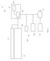
- FIG. 1is a diagrammatic view of the occupant egress prediction system including a person support apparatus, a mattress, and a control system according to one contemplated embodiment of the disclosure;
- FIG. 2is a side perspective view of the person support apparatus of FIG. 1 ;
- FIG. 3is a side perspective view of the person support apparatus of FIG. 1 showing the various components of the upper and lower frame;
- FIG. 4is a side cross-sectional view of the mattress of FIG. 1 showing the various sections and how they correspond to the sections of the upper frame that support the mattress;
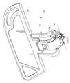
- FIG. 5is a side perspective view of the siderail coupled to the person support apparatus of FIG. 1 showing the base, the movement mechanism and the panel;
- FIG. 6is a partial diagrammatic view of the mattress of FIG. 1 showing the bladders and fluid supply;
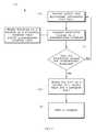
- FIG. 7is a flow chart of a procedure for predicting when a person is going to egress from the person support apparatus according to one contemplated embodiment of the disclosure
- FIG. 8is a flow chart of a procedure for predicting when a person is going to egress from the person support apparatus according to another contemplated embodiment of the disclosure.
- FIG. 9is a flow chart of a procedure for predicting when a person is going to egress from the person support apparatus according to another contemplated embodiment of the disclosure.
- FIG. 10is a flow chart of a procedure for predicting when a person is going to egress from the person support apparatus according to another contemplated embodiment of the disclosure.
- FIG. 11is a flow chart of a procedure for predicting when a person is going to egress from the person support apparatus according to another contemplated embodiment of the disclosure.
- FIG. 1shows an occupant egress prediction system 10 according to one contemplated embodiment.
- the occupant egress prediction system 10includes a person support apparatus 12 , a person support surface 14 or mattress 14 , and a control system 16 .
- the person support apparatus 12is a hospital bed frame and the mattress 14 is supported thereon.
- the person support apparatus 12can be a stretcher, an operating room table, or other person supporting structure.
- the person support apparatus 12includes a lower frame 17 , supports 18 or lift mechanisms 18 coupled to the lower frame 17 , and an upper frame 20 movably supported above the lower frame 17 by the supports 18 .
- the lift mechanisms 18are configured to raise and lower the upper frame 20 with respect to the lower frame 17 and move the upper frame 20 between various orientations, such as, Trendellenburg and reverse Trendellenburg.
- the upper frame 20includes an upper frame base 24 , a deck 26 coupled to the upper frame base 24 , and a plurality of siderails SR as shown in FIGS. 2-4 .
- the deck 26includes a calf section 28 , a thigh section 30 , a seat section 32 , and a head and torso section 34 as shown in FIG. 3 .
- the calf section 28 and the thigh section 30define a lower limb support section LL 1 .
- the head and torso section 34define an upper body support section U 1 .
- the seat section 32defines the seat section S 1 .
- the calf section 28 , the thigh section 30 , and the seat section 32define a lower body support section LB 1 .
- At least the calf section 28 , the thigh section 30 , and the head and torso section 34are movable with respect to one another and/or the upper frame base 24 .
- the calf section 28 , the thigh section 30 , the seat section 32 , and the head and torso section 34cooperate to move the person support apparatus 12 between an substantially planar or lying down configuration and a chair configuration.
- the calf section 28 , the thigh section 30 , the seat section 32 , and the head and torso section 34cooperate to move the person support apparatus 12 between a substantially planar or lying down configuration and an angled or reclined configuration.
- the head and torso section 34is moved such that it is at an angle of at least about 30° with respect to a reference plane RP 1 passing through the upper frame 20 .
- the siderails SRare configured to move between a deployed position and a storage position, and are used to locate the perimeter of the upper frame 24 and assist with ingress/egress to/from the person support apparatus 12 .
- the siderailsinclude a base SB, a movement mechanism SM movably coupled to the base SB, and a panel SP movably coupled to the movement mechanism SM as shown in FIG. 5 .
- a sensor(not shown) is coupled to the siderial SR and configured to sense whether the siderail SR is in the deployed position or in the storage position.
- the senoris a switch coupled to the movement mechanism SM and which is configured to close when the siderail SR reaches the deployed position and open when the siderail SR moves from the deployed position toward the storage position.
- the sensorcan be a contact sensor coupled to the latch mechanism (not shown) that can indicate when the latch mechanism is configured to maintain the siderail SR in the deployed position, or a sensor configured to sense light from a light source that is reflected off the movement mechanism SM when the siderail SR is in the deployed position.
- the person support surface 14is configured to support a person thereon and move with the deck 20 between the various configurations.
- the person support surface 14is a hospital bed mattress 14 as shown in FIGS. 4 and 6 .
- the person support surface 14is a consumer mattress.
- the person support surface 14includes a heat and moisture regulating topper positioned on the mattress.
- the person support surfacecan include a pressure mapping mat positioned on the mattress.
- the person support surface 14includes a calf portion 36 , a thigh portion 38 , a seat portion 40 , and a head and torso portion 42 as shown in FIG. 3 , which is supported on corresponding sections of the deck 26 .
- the deck sectionshelp move and/or maintain the various portions of the mattress 14 at angles ⁇ , ⁇ and ⁇ with respect to the reference plane RP 1 .
- the person support surface 14is a non-powered (static) surface.
- the person support surface 14is a powered (dynamic) surface configured to receive fluid from a fluid supply FS 1 as shown in FIG. 6 .
- the person support surface 14includes a mattress cover 44 and a mattress core 46 enclosed by the mattress cover 44 .
- the mattress core 46can be composed of a single type of material or a combination of materials and/or devices.
- the mattress core 46includes at least one fluid bladder 54 therein that receives fluid from a fluid supply (not shown) to maintain the fluid pressure within the fluid bladder 54 at a predetermined level.
- the powered surfacecan include non-powered components, such as, a foam frame that at least one fluid bladder 54 is positioned between.
- wedge shaped bladdersare mirrored laterally about the centerline of the mattress 14 and are configured to be inflated consecutively to laterally tilt the occupant, thereby relieving pressure on various portions of the occupant's body to help reduce the occurrences of pressure ulcers.
- the mattress core 46is composed of a cellular engineered material, such as, single density foam.
- the mattress core 46includes at least one bladder 54 , such as, a static air bladder or a static air bladder with foam contained there within, a metal spring and/or other non-powered support elements or combinations thereof.
- the mattress core 46and includes multiple zones with different support characteristics configured to enhance pressure redistribution as a function of the proportional differences of a person's body.
- the mattress core 46includes various layers and/or sections of foam having different impression load deflection (ILD) characteristics, such as, in the NP100 Prevention Surface, AccuMax QuantumTM VPC Therapy Surface, and NP200 Wound Surfaces sold by Hill-Rom®.
- ILDimpression load deflection
- the control system 16is configured to determine when an occupant is preparing to egress from the person support structure.
- the control system 16includes a processor 100 , an input 102 , and memory 104 .
- the input 102is a sensor 106 , such as, an image capture device or video camera, a 3D image sensor, a pressure sensor, a temperature sensor, an acoustic sensor, a force sensor, a moisture sensor or other sensor configured to provide patient and environmental information to the processor 100 that is indicative of a physiological characteristic of the occupant, such as, the occupant's heart rate, respiration rate, respiration amplitude, skin temperature, weight, sleep state, body orientation, position and/or other information, a characteristic of the person support apparatus 12 or mattress, such as, whether the siderail SR is in the deployed or storage position, the status of a therapy, the height of the person support apparatus, the configuration of the person support apparatus 12 and/or mattress 14 or other information, and/or a relationship between the occupant and the person support apparatus
- the sensors 106are incorporated into the person support surface 14 or in a topper positioned on the person support surface 14 , for example, as disclosed in U.S. Pat. No. 7,515,059 to Price et al. and U.S. Patent Publication No. 2011/0068928 to Riley et al.
- the sensors 106are load cells coupled to the upper frame 20 .
- the input 102is a user interface 108 configured to receive information from a caregiver or other user.
- the input 102is an Electronic Medical Record (EMR) system 110 in communication with the processor 100 via a hospital network 112 .
- EMRElectronic Medical Record
- the processor 100can output information, automatically or manually upon caregiver input, to the EMR for charting, which can include therapy initiation and termination, adverse event occurrence information, therapy protocol used, caregiver ID, and any other information associated with the occupant, caregiver, person support apparatus 12 , person support surface 14 , and adverse event.
- the input 102is a pressure mapping mat positioned on the person support surface 14 .
- the inputs 102provide patient and environmental information that may include both spatial and temporal components and may relate to a variety of things, including, but not limited to, the person's current diagnosis, medications the person is taking, the person's physiological characteristics, the person's medical history, risk assessments performed by a caregiver, medical procedures the person has undergone, the status of medical equipment in the vicinity of the person or that is associated with the person (i.e., the person support apparatus 12 and the person support surface 14 ), care facility protocols and procedures, care facility logistics, caregiver or patient inputs, and other information about the person, medical devices, caregivers, and care facility that can be provided by an EMR or a patient activity log, gathered by and from the person support apparatus 12 and mattress 14 and other medical devices assigned to the person, or through the care facility network.
- the person's current diagnosis, medications the person is takingthe person's physiological characteristics, the person's medical history, risk assessments performed by a caregiver, medical procedures the person has undergone, the status of medical equipment in the vicinity of the person or that is associated with the person
- the information from the inputs 102can be grouped into the following categories: prerequisite condition inputs, motivating condition inputs, preparation sequence inputs, facility/unit inputs, and caregiver/patient inputs.
- Prerequisite condition inputs and motivating condition inputscan come from a number of sources, including, but not limited to, the occupant's electronic medical EMRs, patient activity logs, caregiver notes or activity logs, information sensed and tracked by the occupant support structure, the hospital network, or other sources of information.
- the prerequisite condition inputsinclude information that makes it more likely that an occupant could egress from the person support structure 12 .
- a prerequisite conditionis whether the siderail coupled to the person support structure 12 is lowered so that a person can egress from the support structure.
- Another example of a prerequisite condition inputis whether the person is conscious.
- the motivating condition inputsinclude information that could make it more likely that a person would need or want to egress from the person support structure 12 .
- One example of a motivating condition inputincludes objective factors that, if detected would indicate that the person needs to go to the bathroom and will attempt to egress from the support structure 12 in the near future, such as, the person being able to walk, increased movement of the person on the support structure 12 , greater than 6 hours since the person last toileted, an I/O balance of greater than 400 mL, a lack of catheterization, and a lack of an incontinence pad, among others.
- the preparation sequence inputsinclude information about the person's movement, posture, and other activities over time that are indicative of an person preparing to egress from the support structure.
- Preparation sequence inputscan be sensed using techniques that include, but are not limited to, image capture, pressure sensing, visual sensing, motion detection, position detection, and proximity detection, and are distinguishable from other inputs that do not generally indicate that a person is preparing to egress from the support structure 12 .
- One example of a preparation sequenceis where a person moves from an initial position, i.e., the supine position, to a position where the person is increasing the amount of weight supported by their pivoting elbow and/or increases their torso angle with respect to the support structure 12 .
- the patient/caregiver inputsinclude information entered by the caregiver and/or the patient.
- the patient/caregiver inputs and facility/unit inputscan be used to adjust the weighting of the other inputs.
- One example of a patient/caregiver inputis the caregiver's personal preference for alarms.
- the facility/unit inputsinclude information about the facility's and/or the unit's protocols, logistics, and other information.
- Some examples of facility/unit inputsinclude the patient population, case-mix, culture, varying patterns of the facility and/or unit, risk tolerance (low-level or high-level), time of day, staffing levels, when the caregivers are going to be making their rounds, and likelihood of an alarm being responded to within a predetermined amount of time, among other things.
- the memory 104stores one or more instruction sets configured to be executed by the processor 100 when the occupant egress prediction system 10 is armed.
- the occupant egress prediction system 10is armed manually by the caregiver or automatically based on information from the patient's EMR, the caregiver, and/or a protocol triggered by the risk profile of the patient.
- the instruction setsdefine procedures 114 that cause the processor 100 to implement one or more protocols that alert a caregiver via a communication system (not shown) when the system 10 predicts that the person supported on the person support apparatus 12 will egress from the person support apparatus 12 in the near future.
- the communication systemcan be used to alert a caregiver proximate to the person support apparatus 14 (i.e., in the same room or in the hall way connected to the room) and a caregiver remote from the person support apparatus 14 .
- the communication systemis a patient/nurse call system that can include patient stations capable of generating hospital calls and a remote master station which can prioritize and store the calls.
- a patient/nurse call systemcan include patient stations capable of generating hospital calls and a remote master station which can prioritize and store the calls.
- U.S. Pat. No. 5,561,412 issued on Oct. 1, 1996 to Novak et al.which is incorporated by reference herein in its entirety.
- Another example of such a systemis disclosed in U.S. Pat. No.
- the communication systemcan include a status board that displays the alert.
- the communication systemcan alert the caregiver by posting the alert to a status board, using a nurse call system, directly contacting the caregiver on their phone or pager, providing a local alert over the facility PA system, and opening a connection that allows the caregiver to speak directly to the patient.
- the communicationcan also escalate the vigilance monitoring of the patient.
- the communication systemis a system for transmitting voice and data in packets over a network with any suitable number of intra-room networks that can couple a number of data devices to an audio station, where the audio station couples the respective intra-room network to a packet based network.
- a systemfor transmitting voice and data in packets over a network with any suitable number of intra-room networks that can couple a number of data devices to an audio station, where the audio station couples the respective intra-room network to a packet based network.
- U.S. Pat. No. 7,315,535 issued on Jan. 1, 2008 to Schumanwhich is incorporated by reference herein in its entirety.
- Another example of such a systemis disclosed in U.S. Patent Publication No. 2008/0095156 issued on Apr. 24, 2008 to Schuman, which is incorporated by reference herein in its entirety.
- the communication systemis included a patient/nurse call system, a nurse call/locating badge, an electronic medical record (EMR) database, and one or more computers programmed with work-flow process software.
- EMRelectronic medical record
- One example of such a systemis disclosed in U.S. Patent Publication No. 2008/0094207 published on Apr. 24, 2008 to Collins, J R. et al., which is incorporated by reference herein in its entirety.
- Another example of such a systemis disclosed in U.S. Patent Publication No. 2007/0210917 published on Sep. 13, 2007 to Collins, J R. et al., which is incorporated by reference herein in its entirety.
- Yet another example of such a systemis disclosed in U.S. Pat. No. 7,319,386 published on Jan.
- the work-flow process softwarecan be the NaviCare® software available from Hill-Rom Company, Inc. It should also be appreciated that the work-flow process software can be the system disclosed in U.S. Pat. No. 7,443,303 issued on Oct. 28, 2008 to Spear et al., which is incorporated by reference herein in its entirety. It should further be appreciated that the badge can be of the type available as part of the ComLinxTM system from Hill-Rom Company, Inc. It should also be appreciated that the badge can also be of the type available from Vocera Communications, Inc.
- the communication systemis configured to organize, store, maintain and facilitate retrieval of bed status information, along with the various non-bed calls placed in a hospital wing or ward, and remotely identify and monitor the status and location of the person support apparatus, patients, and caregivers.
- a hospital wing or wardOne example of such a system is disclosed in U.S. Pat. No. 7,242,308 issued on Jul. 10, 2007 to Ulrich et al., which is incorporated by reference herein in its entirety.
- the remote status and location monitoringcan be the system disclosed in U.S. Pat. No. 7,242,306 issued on Jul. 10, 2007 to Wildman et al., which is incorporated by reference herein in its entirety.
- the remote status and location monitoringcan be the system disclosed in U.S. Patent Publication No. 2007/0247316 published on Oct. 25, 2007 to Wildman et al., which is incorporated by reference herein in its entirety.
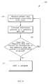
- the instruction setdefines a threshold recognition procedure 114 that causes the processor 100 to send the caregiver an alert via a communication system (not shown) upon determining that a predetermined threshold has been exceeded by the information from the inputs 102 as shown in FIG. 7 .
- Procedure 114begins with step 116 in which the processor 100 receives patient and environmental information from the input 102 .
- the information from the input 102may indicate that the person is awake, the siderail SR is down, and the person is positioned on their side and is using their elbow to prop themselves up.
- a pressure mapping padcan be positioned on the mattress 14 and can identify where the localized pressure increase is with respect to the perimeter of the upper frame 20 .
- step 118the processor 100 compares the information it received in step 116 to a predetermined threshold to determine if/when the person is going to egress from the person support apparatus 12 .
- a predetermined thresholdif a person has increased the weight supported by their elbow, there may be an increased likelihood that the person will attempt to egress from the person support apparatus 12 in the near future.
- information in the prerequisite condition input and motivating condition input categoriescan be used to raise or lower the threshold. For example, if the person is awake, the siderail SR is in the storage position, and the person has not toileted in more than 6 hours, the threshold may be lowered because the likelihood that the person will egress from the person support apparatus 14 may be higher.
- step 120the processor 100 examines information in the facility/unit input and patient/caregiver input categories to determine if the caregiver should be alerted, knowing that an egress event will likely occur. For example, if the information indicates that the caregiver is scheduled to visit the patient within the next few minutes, an alert may not be sent.
- an alertis sent to the caregiver in step 122 .
- the instruction setcauses the processor 100 to carry out a sequence recognition procedure 124 that determines if the person's movements over time are indicative of someone who is going to egress from the person support apparatus 12 as shown in FIG. 8 .
- a sequence of movements that may indicate a person is going to exit the person support apparatus 12is shown in the table below:
- Sleep sensor or sensing systemindicates the Exit within the next 10 minutes may be low patient is sleeping Sleep sensor or sensing system indicates the Exit within the next 10 minutes may still be patient is waking low, but may be increased from previous Location/tracking system indicates last analysis toileting 8.2 hours ago Pressure map indicates leg movement from Exit within the next 10 minutes may be lateral to bent medium Activity sensor indicates frequent repositioning or fidgeting Pressure map indicates rotation onto left side Exit within the next 10 minutes may be high.
- Exit within the next 5 minutesmay be medium Pressure map indicates increased weight Exit within the next 10 minutes may be high supported on right elbow and may be increased from previous analysis Exit within the next 5 minutes may be medium Pressure map indicates increased weight Exit within the next 10 minutes may be high supported on elbow and increased weight and may be increased from previous analysis supported on buttocks Exit within the next 5 minutes may be high
- Procedure 124begins with step 126 where the processor 100 receives a first set of patient and environmental information from the input 102 .
- the processor 100receives a first position of the person with respect to the person support apparatus 12 .
- step 128the processor 100 receives a second set of patient and environmental information from the input.
- the processor 100compares the second set of information and the first set of information to an egress profile. For example, if a person wakes, turns onto their side, and places their hand on the person support apparatus 12 , there may be an increased likelihood that the person will attempt to egress from the person support apparatus 12 in the near future. In other examples, an increased likelihood that the person will attempt to egress from the bed in the near future may be indicated by a pelvis leading and lateral roll for the head and trunk and a lateral lift and push for the far arm, or a legs first see-saw motion for the head and trunk, a reach across the midline and push for the far arm, a multi-push for the near arm, and a synchronous movement of the legs.
- the egress profilecan be learned over time by monitoring the person and identifying common characteristics or patterns that precede the person attempting to egress from the person support apparatus 12 .
- the egress profilecan be derived from data collected in studies that examine common traits associated with egress from a person support apparatus 12 .
- One example of such a patternmay be where the person repeatedly presses against the siderails to lift their body prior to attempting to egress form the person support apparatus 12 .
- repeated motions while the person is sleepingmay indicate that the person will attempt to egress from the person support apparatus 12 .
- step 132the processor 100 examines information in the facility/unit input and patient/caregiver input categories to determine if the caregiver should be alerted, knowing that an egress event will likely occur. Once it is determined that the person is likely going to exit the person support apparatus 14 in the near future, an alert is sent to the caregiver in step 134 .
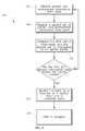
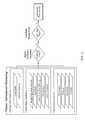
- the instruction setcauses the processor 100 to carry out a data fusion procedure 136 that compares the totality of the inputs with a reference data set to identify patterns correlated with a person preparing to egress as shown in FIG. 9 .
- Procedure 136begins with step 138 where the processor 100 receives patient and environmental information from the input 102 .
- step 140the processor 100 compares the information corresponding to the person's current pattern of activity with a reference data set to determine the frequency that the current pattern was followed by another person in the reference data set.
- a reference data setOne example of a way large data sets can be combined and visualized is disclosed in Visualisation of High - Dimensional Data for Very Large Data Sets by Wong et al. appearing in Proceedings of the Workshop on Machine Learning for Health Care Applications, 25 th International Conference on Machine Learning .
- Another way the information could be combined and used to predict the likelihood of an egress eventis using the Visensia® software sold by OBS Medical.
- the frequency that the pattern follows the reference data setexceeds a predetermined threshold, then the person is likely going to exit the person support apparatus 14 in the near future and an alert is sent to the caregiver in step 142 .
- the instruction setcauses the processor 100 to carry out a multivariate procedure 144 that assigns a value to information and determines if a predetermined threshold value is exceeded as shown in FIG. 10 .
- Procedure 144begins with step 146 where the processor 100 receives patient and environmental information from the input 102 .
- the processor 100assigns a value to the various pieces of information based on their relative importance to conditions sensed by the system.
- the valueis determined based on statistical analysis of historical data sets showing prior events in similar situations. For example, the following values may be assigned to the information below:
- a thresholdmay be set to identify when a person is likely to egress from the person support apparatus 12 .
- a personmay be very likely to egress from a person support apparatus 14 if they score above 10 points for the information provided above.
- step 150the processor 100 sums the values assigned to the information.
- step 152the processor 100 compares the summed value with a predetermined threshold.
- an alertis sent to the caregiver in step 154 .
- multiple procedures or algorithmscan act in parallel and can trigger a response as shown in FIG. 11 .
- control system 16can provide decision support.
- the control system 16can be used to analyze available data to evaluate risk and propose activities to help reduce the risk.
- the system 16can take into account whether a caregiver is present, what the status of the siderail is, and what the status of the lighting in the room is.
- the system 16can determine whether the person is a falls risk based on the caregiver assessment, the person's EMR or patient history, and/or the current medical diagnosis and status of the person.
- the systemcan also recommend interventions for minimizing the falls risk, such as leaving a walker in the room after physical therapy and/or leaving fluids in the room to reduce dehydration which may exacerbate confusion.
- logged HIPAA compliant datacan be uploaded to a central database for analysis.
- algorithms or procedures used by the system 16may be remotely upgradable.
- a methodcomprises sensing a first characteristic indicative of an occupant's status on an occupant support structure; sensing a second characteristic indicative of an occupant's status on the occupant support structure; determining if am occupant is preparing to exit the occupant support structure based on the first characteristic and the second characteristic; if an occupant is preparing to exit the occupant support structure, alerting a caregiver.
- determining if an occupant is preparing to exit the occupant support structureby comparing the first characteristic to the second characteristic; if the difference between the first characteristic and the second characteristic is greater than a predetermined threshold, alerting a caregiver that the occupant is preparing to exit the occupant support structure.
- the first and second characteristicsare indicative of the occupant's location with respect to the occupant support structure. In another contemplated embodiment, the first and second characteristics are indicative of the occupant's orientation with respect to the occupant support structure. In another contemplated embodiment, the first and second characteristics are indicative of the location of the occupant's center of gravity with respect to the occupant support structure. In another contemplated embodiment, the method further comprises the step of sensing a third characteristic indicative of the occupant's level of consciousness. In another contemplated embodiment, the first and second characteristics are indicative of the occupant's movement with respect to the occupant support structure. In another contemplated embodiment, the first and second characteristics are sensed using at least one fluid pressure sensor coupled to the occupant support structure.
- the first and second characteristicsare sensed using a three dimensional sensing device coupled to the occupant support structure. In another contemplated embodiment, the first and second characteristics are sensed using a three dimensional sensing device coupled proximate to the occupant support structure. In another contemplated embodiment, the first and second characteristics are sensed using a video camera coupled to the occupant support structure. In another contemplated embodiment, the first and second characteristics are sensed using a video camera coupled proximate to the occupant support structure. In another contemplated embodiment, the first and second characteristics are sensed using a force sensor coupled to the occupant support structure. In another contemplated embodiment, the first and second characteristics are sensed using a force sensor coupled to a topper positioned on the occupant support structure.
- the methodfurther comprises the steps of: sensing a characteristic of the occupant support structure; and if the characteristic of the occupant support structure is equal to a predetermined value, then alerting a caregiver that the occupant is preparing to exit the occupant support structure.
- the characteristic of the occupant support structureis indicative of the position of the siderail.
- the characteristic of the occupant support structureis indicative of the height of the occupant support structure.
- the characteristic of the occupant support structureis indicative the occupant support structure's configuration.
- the characteristicis indicative of a head end of the occupant support structure being raised.
- the characteristic of the occupant support structureis indicative of the status of a therapy provided by the person occupant support structure.
- the methodfurther comprises the steps of: evaluating a care facility input; and if the characteristic of the care facility is equal to a predetermined value, then alerting a caregiver that the occupant is preparing to exit the occupant support structure.
- the care facility inputis indicative of the care facility's protocols.
- the care facility inputis indicative of an input from a caregiver.
- the care facility inputis indicative of the level of staffing at the care facility.
- the care facility inputis indicative of the time of day.
- the care facility inputis indicative of an event at the care facility.
- the methodfurther comprises the steps of: determining a motivating condition of the occupant; and if the motivating condition is equal to a predetermined value, then alerting a caregiver that the occupant is preparing to exit the occupant support structure.
- the motivating conditionis a noise.
- the motivating conditionis an unanswered nurse call.
- the motivating conditionis use of a restroom.
- the motivating conditionis determined based on information from the occupant's electronic medical record.
- the motivating conditionis determined based on information collected by sensors on the occupant support structure. In another contemplated embodiment, the motivating condition is determined as a function of the amount of time that has lapsed since the occupant last exited the occupant support structure. In another contemplated embodiment, the motivating condition is determined as a function of the occupant's medical condition. In another contemplated embodiment, the motivating condition is determined as a function of the type of medication the occupant is taking.
- a systemcomprises an occupant support structure, a sensor, and a control system.
- the occupant support structureis configured to support an occupant thereon.
- the sensoris coupled to the occupant support structure and configured to sense a characteristic of the occupant supported on the occupant support structure.
- the control systemis configured to determine when the occupant is preparing to exit the occupant support structure as a function of the characteristic sensed by the sensor.
- the sensorsenses the occupant's position on the occupant support structure.
- the sensoris a load cell.
- the sensoris a force sensor.
- the sensoris a fluid pressure sensor.
- the sensoris a temperature sensor.
- the occupant support structureincludes a mattress and a topper positioned on the mattress.
- the topperis a pressure mapping mat.
- the control systemdetermines that an occupant is preparing to exit the occupant support structure when the difference between a current occupant pressure map profile and a previous occupant pressure map profile exceeds a predetermined threshold.
- the occupant support structureincludes a lower frame, at least one support coupled to the lower frame, and an upper frame movably supported above the lower frame by the support.
- a methodcomprises receiving information corresponding to at least one of the position, orientation, and activity level of a person supported on a person support apparatus, determining if the person will likely attempt to egress from the person support structure in the near future based on the information; if the person will likely attempt to egress from the person support structure in the near future, alerting a caregiver. In one contemplated embodiment, determining if the person will likely attempt to egress from the person support structure in the near future by comparing the characteristic to a predetermined threshold; if the characteristic exceeds the predetermined threshold, alerting a caregiver that the person will likely attempt to egress from the person support structure in the near future.
- the thresholdis adjusted based on at least one of a prerequisite condition, a caregiver input, a facility input, and a motivating condition.
- the prerequisite conditionincludes at least one of a status of a siderail and the person's sleep state.
- the motivating conditionincludes at least one of the time since the person last toileted, the amount of body movement, whether the person can walk, the I/O balance being greater than about 400 ml, the lack of catheterization, and the lack of an incontinence pad.
- the facility inputsinclude at least one of the level of risk tolerance, care facility protocols, the staffing level of the facility, the time of day, the schedule of rounds for the caregivers, the patient population, the patient case mix, the culture varying patterns of the facility, and the need for detail.
- the caregiver inputsinclude at least adjustment of the alarms, a personal preference for alarms, and the agitation level of the patient.
- informationis received from at least one of an optical camera, an infrared camera, a thermal camera, a Doppler sensing system, an accelerometer, a pressure mapping system, a motion detector, a patient position monitoring system, a center of gravity detecting system, a weight scale system, a caregiver via an input device, an electronic medical record, a patient record, and a pharmacy record.
- a methodcomprises receiving at least one characteristic of at least one of a person support structure, a person supported on the person support structure, and a facility where the person and the person support structure are located; assigning a value to each of the at least one characteristic; summing the values for the at one characteristic; comparing the summed values to a predetermined threshold; if the summed values exceed the predetermined threshold, alerting a caregiver that the person will likely attempt to egress from the person support structure in the near future.
- a method of predicting an egress conditioncomprises the steps of: receiving a first input signal indicative of a motivating condition that would cause a person to egress from a person support structure; determining when an egress condition will likely occur based on the first input and generating an alert if an egress condition will occur. In one contemplated embodiment, determining when an egress condition will occur by comparing the first input to a predetermined threshold; and generating an alert if the first input exceeds the predetermined threshold.
- the motivating conditionincludes time since the person last toileted. In another contemplated embodiment, the time is greater than 6 hours. In another contemplated embodiment, the motivating condition includes absence of an incontinence pad.
- the motivating conditionincludes I/O balance of greater than 400 mL. In another contemplated embodiment, the motivating condition includes absence of catheterization. In another contemplated embodiment, the motivating condition includes movement of a person with respect to the person support structure increasing over a predetermined period of time.
- a method of predicting an egress condition for a person supported on a person support structurecomprises the steps of: receiving an input signal indicative of movement of a person with respect to the person support structure; comparing the input signal to a predetermined egress profile; generating an alert if the input signal is about equal to a portion of the predetermined egress profile.
- the input signalincludes information sensed by a pressure map.
- the input signalincludes information sensed by a load cell.
- the input signalincludes information sensed by an image capture device.
- the input signalincludes information sensed by a 3D image sensor.
- the input signalincludes information sensed by an array of sensors and the person support structure includes a mattress, wherein the array of sensors is coupled to the mattress.
- a method of predicting an egress condition for a person supported on a person support structurecomprises the steps of: receiving input signals corresponding to at least two of: an egress motivating condition; an egress prerequisite condition; an egress preparation sequence; determining when an egress condition will likely occur, and generating an alert if an egress condition will likely occur.
- determining when an egress condition will likely occurby comparing the input signals to a predetermined threshold; and generating an alert if at least one of the input signals exceeds the predetermined threshold.
- the egress motivating conditionincludes time since the person last toileted. In another contemplated embodiment, the time is greater than 6 hours.
- the egress motivating conditionincludes absence of an incontinence pad. In another contemplated embodiment, the egress motivating condition includes I/O balance of greater than 400 mL. In another contemplated embodiment, the egress motivating condition includes absence of catheterization. In another contemplated embodiment, the egress motivating condition includes movement of a person with respect to the person support structure increasing over a predetermined period of time. In another contemplated embodiment, the egress preparation sequence includes information sensed by a pressure map. In another contemplated embodiment, the egress preparation sequence includes information sensed by a force sensor. In another contemplated embodiment, the egress preparation sequence includes information sensed by an image capture device.
- the egress preparation sequenceincludes information sensed by a 3D image sensor. In another contemplated embodiment, the egress preparation sequence includes information sensed by an array of sensors and the person support structure includes a mattress, wherein the array of sensors is coupled to the mattress. In another contemplated embodiment, the egress prerequisite condition includes information indicative of a person's level of consciousness. In another contemplated embodiment, the egress prerequisite condition includes information corresponding to a status of the person support structure. In another contemplated embodiment, the status of the person support structure includes the position of a siderail. In another contemplated embodiment, the egress prerequisite condition includes information corresponding to a status of a therapy.
- At least one of the input signals corresponding to at least one of the egress prerequisite condition and the egress motivating conditionis provided by an electronic medical record system. In another contemplated embodiment, at least one of the input signals corresponding to at least one of the egress prerequisite condition and the egress motivating condition is provided by a caregiver via a graphical user interface. In another contemplated embodiment, at least one of the input signals corresponding to at least one of the egress prerequisite condition and the egress motivating condition and the egress preparation sequence is provided by sensors coupled to the person support structure. In another contemplated embodiment, the method further comprises the step of receiving an input signal corresponding to a facility input and modifying the predetermined threshold as a function of the facility input.
- the facility inputincludes information corresponding to a facility protocol. In another contemplated embodiment, the facility input includes information corresponding to facility logistics. In another contemplated embodiment, the facility input includes information corresponding to at least one of the patient population, case-mix, culture, facility patterns, risk tolerance, time of day, staffing levels, caregiver round times, and likelihood an alert will be responded to within a predetermined amount of time. In another contemplated embodiment, the method further comprises the step of receiving an input signal corresponding to a facility input and modifying the alert as a function of the facility input. In another contemplated embodiment, the method further comprises the step of receiving an input signal corresponding to a caregiver input and modifying the alert as a function of the caregiver input.
- the methodfurther comprises the step of receiving an input signal corresponding to a caregiver input and modifying the predetermined threshold as a function of the caregiver input.
- the caregiver inputincludes a caregiver alarm preference.
- the alertis communicated to a caregiver via a nurse call system.
- the alertis communicated to a caregiver by the person support structure.
- the person support structureincludes an upper frame movably supported above a lower frame by a lift mechanism.
- the person support structureincludes a mattress including at least one fluid bladder.
- the egress prerequisite conditionincludes information corresponding to physiological characteristics of a person supported on the person support structure.
- the egress preparation sequenceincludes information corresponding to the location of a person supported on the person support structure. In another contemplated embodiment, the egress preparation sequence includes information corresponding to the center of gravity of a person supported on the person support structure. In another contemplated embodiment, the egress preparation sequence includes information sensed by a fluid pressure sensor coupled to a fluid bladder of the person support structure. In another contemplated embodiment, the egress prerequisite condition includes information corresponding to the configuration of the person support structure. In another contemplated embodiment, the egress motivating condition includes an unanswered nurse call. In another contemplated embodiment, the egress motivating condition includes the time since a person last egressed from the person support structure.
- the egress motivating conditionincludes information corresponding to the medical condition of a person.
- the medical condition of a personincludes information corresponding to at least one of a medical procedure a person underwent recently and medication a person is currently taking.
- the egress prerequisite conditionincludes information corresponding to a fall risk analysis for a person.
- a method of predicting an egress condition for a person supported on a person support structurecomprises the steps of: receiving a first input signal corresponding to a characteristic of a person; receiving a second input signal corresponding to a characteristic of a facility; determining when an egress condition will likely occur based on the first input signal, generating an alert to indicate that a person is predicted to egress from the person support structure; and modifying the alert as a function of the second input signal.
- determining when an egress condition will likely occurby comparing the first input signal to a predetermined threshold; if the first input signal exceeds the predetermined threshold.
- the predetermined thresholdis modifiable as a function of a third input signal corresponding to an egress motivating condition. In another contemplated embodiment, the predetermined threshold is modifiable as a function of a third input signal corresponding to an egress prerequisite condition.
- a method of predicting an egress condition for a person supported on a person support structurecomprises the steps of: receiving a first input signal corresponding to a characteristic of a person; receiving a second input signal corresponding to an input from a caregiver; determining when an egress condition will likely occur based on the first input signal, generating an alert to indicate when an egress condition will likely occur; and modifying the alert as a function of the second input signal.
- the methodincludes the steps of comparing the first input signal to a predetermined threshold; if the first input signal exceeds the predetermined threshold, generating an alert to indicate that a person is predicted to egress from the person support structure
- a method of predicting an egress condition for a person supported on a person support structurecomprises the steps of: receiving a first input signal corresponding to a characteristic of a person; comparing the first input signal to a predetermined egress profile; if the first input signal matches a portion of the egress profile, generating an alert to indicate that a person is predicted to egress from the person support structure
- the alertis modifiable as a function of a second input signal corresponding to a characteristic of a facility.
- the alertis modifiable as a function of a second input signal corresponding to an input from a caregiver.
- a method of predicting an egress condition for a person supported on a person support structurecomprises the steps of: receiving a plurality of input signals corresponding to at least one of: a characteristic of a person supported on the person support structure; a status of the person support structure; a motivating condition; a prerequisite condition; a preparation sequence; comparing the plurality of inputs to a reference data set; if the frequency that the input signals correspond to the reference data set exceeds a predetermined threshold, generating an alert.
- a method of predicting an egress condition for a person supported on a person support structurecomprises the steps of: receiving a plurality of input signals corresponding to at least one of: a characteristic of a person supported on the person support structure; a status of the person support structure; a motivating condition; a prerequisite condition; a preparation sequence; assigning a value to each input signal based on a predetermined list of input value; summing the values for the input signals and comparing the summed value to a predetermined threshold; and generating an alert if the summed value exceeds the predetermined threshold.
- a control system for determining when a person will egress from a person support structurecomprises a plurality of input devices, a processor, and a memory unit.
- the processoris configured to receive input signals from the plurality of input devices corresponding to at least two of: an egress motivating condition, an egress prerequisite condition, and an egress preparation sequence.
- the memory unitincludes instructions that cause the processor to compare the input signals to a predetermined threshold and generate an alert in response to the input signals exceeding the predetermined threshold.
- the memory unitincludes instructions that cause the processor to determine when an egress condition is likely to occur based on the input signals and generate an alert if the processor determines that an egress condition is likely to occur.
- the processor and memoryare coupled to the person support structure.
- at least one of the plurality of input devicesincludes a sensor coupled to the person support structure.
- the person support structureincludes a mattress including at least one fluid bladder.
- the person support structureincludes a frame including an upper frame movably supported above a lower frame by a lift mechanism.
- the egress motivating conditionincludes time since the person last toileted. In another contemplated embodiment, the time is greater than 6 hours. In another contemplated embodiment, the egress motivating condition includes absence of an incontinence pad.
- the egress motivating conditionincludes I/O balance of greater than 400 mL. In another contemplated embodiment, the egress motivating condition includes absence of catheterization. In another contemplated embodiment, the egress motivating condition includes movement of a person with respect to the person support structure increasing over a predetermined period of time. In another contemplated embodiment, the egress preparation sequence includes information sensed by a pressure map. In another contemplated embodiment, the egress preparation sequence includes information sensed by a force sensor. In another contemplated embodiment, the egress preparation sequence includes information sensed by an image capture device. In another contemplated embodiment, the egress preparation sequence includes information sensed by a 3D image sensor.
- the egress preparation sequenceincludes information sensed by an array of sensors and the person support structure includes a mattress, wherein the array of sensors is coupled to the mattress.
- the egress prerequisite conditionincludes information indicative of a person's level of consciousness.
- the egress prerequisite conditionincludes information corresponding to a status of the person support structure.
- the status of the person support structureincludes the position of a siderail.
- the egress prerequisite conditionincludes information corresponding to a status of a therapy.
- at least one of the input signals corresponding to at least one of the egress prerequisite condition and the egress motivating conditionis provided by an electronic medical record system.
- At least one of the input signals corresponding to at least one of the egress prerequisite condition and the egress motivating conditionis provided by a caregiver via a graphical user interface.
- at least one of the input signals corresponding to at least one of the egress prerequisite condition and the egress motivating condition and the egress preparation sequenceis provided by sensors coupled to the person support structure.
- the input deviceis configured to receive an input signal corresponding to a facility input and the instructions cause the processor to modify the predetermined threshold as a function of the facility input.
- the facility inputincludes information corresponding to a facility protocol.
- the facility inputincludes information corresponding to facility logistics.
- the facility inputincludes information corresponding to at least one of the patient population, case-mix, culture, facility patterns, risk tolerance, time of day, staffing levels, caregiver round times, and likelihood an alert will be responded to within a predetermined amount of time.
- the input deviceis configured to receive an input signal corresponding to a facility input and the instructions cause the processor to modify the alert as a function of the facility input.
- the input deviceis configured to receive an input signal corresponding to a caregiver input and the instructions cause the processor to modify the alert as a function of the caregiver input.
- the input deviceis configured to receive an input signal corresponding to a caregiver input and the instructions cause the processor to modify the predetermined threshold as a function of the caregiver input.
- the caregiver inputincludes a caregiver alarm preference.
- the alertis communicated to a caregiver via a nurse call system.
- the alertis communicated to a caregiver by the person support structure.
- the egress prerequisite conditionincludes information corresponding to physiological characteristics of a person supported on the person support structure.
- the egress preparation sequenceincludes information corresponding to the location of a person supported on the person support structure.
- the egress preparation sequenceincludes information corresponding to the center of gravity of a person supported on the person support structure.
- the egress preparation sequenceincludes information sensed by a fluid pressure sensor coupled to a fluid bladder of the person support structure.
- the egress prerequisite conditionincludes information corresponding to the configuration of the person support structure.
- the egress motivating conditionincludes an unanswered nurse call.
- the egress motivating conditionincludes the time since a person last egressed from the person support structure.
- the egress motivating conditionincludes information corresponding to the medical condition of a person.
- the medical condition of a personincludes information corresponding to at least one of a medical procedure a person underwent recently and medication a person is currently taking.
- the egress prerequisite conditionincludes information corresponding to a fall risk analysis for a person.
- a control system for determining a person's position on a person support structurecomprises an input device and a controller.
- the input deviceis configured to sense the location of a person's heart.
- the controlleris configured to determine if the person is at least one of preparing and attempting to egress from the person support structure as a function of the sensed location of the person's heart.
- the controlleralerts a caregiver if the person is determined to be at least one of preparing and attempting to egress.
- a control system for determining when a person will egress from a person support structurecomprises a plurality of input devices, a processor, and a memory unit.
- the processoris configured to receive input signals from the plurality of input devices corresponding to at least two of a patient parameter associated with the likelihood of a patient egressing from the person support structure; an equipment parameter associated with the ability of the patient to egress from the person support structure; and a patient movement parameter indicative of patient movement on the person support structure.
- the memory unitincludes instructions that cause the processor to determine if an egress condition is occurring based upon the input signals and to generate an alert if an egress condition is determined.
- a control system for determining when a person will egress from a person support structurecomprises a plurality of input devices, a processor, and a memory unit.
- the processoris configured to receive a first input indicative of an egress motivating condition.
- the memory unitincludes instructions that cause the processor to determine if an egress condition is likely to occur based on the first input, and to monitor for a second input indicative of at least one of an egress prerequisite condition and an egress preparation sequence.
- a control system for determining when a person will egress from a person support structurecomprises a plurality of input devices, a processor, and a memory unit.
- the processoris configured to receive input signals indicative of the person's sleep state and a person support structure status.
- the memory unitincludes instructions that cause the processor to determine if an egress condition is likely to occur based on the input signals, and generating an alert generate an alert if an egress condition is determined to be likely.
Landscapes
- Health & Medical Sciences (AREA)
- Life Sciences & Earth Sciences (AREA)
- General Health & Medical Sciences (AREA)
- Animal Behavior & Ethology (AREA)
- Public Health (AREA)
- Veterinary Medicine (AREA)
- Physics & Mathematics (AREA)
- Nursing (AREA)
- Surgery (AREA)
- Molecular Biology (AREA)
- Medical Informatics (AREA)
- Biophysics (AREA)
- Pathology (AREA)
- Engineering & Computer Science (AREA)
- Biomedical Technology (AREA)
- Heart & Thoracic Surgery (AREA)
- Emergency Management (AREA)
- Business, Economics & Management (AREA)
- General Physics & Mathematics (AREA)
- Physiology (AREA)
- Gerontology & Geriatric Medicine (AREA)
- Dentistry (AREA)
- Oral & Maxillofacial Surgery (AREA)
- Social Psychology (AREA)
- Psychology (AREA)
- Psychiatry (AREA)
- Measuring And Recording Apparatus For Diagnosis (AREA)
- Invalid Beds And Related Equipment (AREA)
- Accommodation For Nursing Or Treatment Tables (AREA)
- Alarm Systems (AREA)
- Medical Treatment And Welfare Office Work (AREA)
- Emergency Alarm Devices (AREA)
- Traffic Control Systems (AREA)
Abstract
Description
| Input | Analysis |
| Sleep sensor or sensing system indicates the | Exit within the next 10 minutes may be low |
| patient is sleeping | |
| Sleep sensor or sensing system indicates the | Exit within the next 10 minutes may still be |
| patient is waking | low, but may be increased from previous |
| Location/tracking system indicates last | analysis |
| toileting 8.2 hours ago | |
| Pressure map indicates leg movement from | Exit within the next 10 minutes may be |
| lateral to bent | medium |
| Activity sensor indicates frequent repositioning | |
| or fidgeting | |
| Pressure map indicates rotation onto left side | Exit within the next 10 minutes may be high. |
| Exit within the next 5 minutes may be medium | |
| Pressure map indicates increased weight | Exit within the next 10 minutes may be high |
| supported on right elbow | and may be increased from previous analysis |
| Exit within the next 5 minutes may be medium | |
| Pressure map indicates increased weight | Exit within the next 10 minutes may be high |
| supported on elbow and increased weight | and may be increased from previous analysis |
| supported on buttocks | Exit within the next 5 minutes may be high |
| Walking in the past 10 minutes | 5 points | ||
| Not catheterized | 2 points | ||
| No underpad present | 1 point | ||
| 8 hours since last toileting | 5 points | ||
| Siderail up | −2 points | ||
| Activity score 7 | 1 point | ||
Also based on the historical data, a threshold may be set to identify when a person is likely to egress from the
Claims (19)
Priority Applications (4)
| Application Number | Priority Date | Filing Date | Title |
|---|---|---|---|
| US13/900,115US9165449B2 (en) | 2012-05-22 | 2013-05-22 | Occupant egress prediction systems, methods and devices |
| US14/857,006US9552714B2 (en) | 2012-05-22 | 2015-09-17 | Occupant egress prediction systems, methods and devices |
| US15/383,462US9761109B2 (en) | 2012-05-22 | 2016-12-19 | Occupant egress prediction systems, methods and devices |
| US15/680,530US9978244B2 (en) | 2012-05-22 | 2017-08-18 | Occupant falls risk determination systems, methods and devices |
Applications Claiming Priority (2)
| Application Number | Priority Date | Filing Date | Title |
|---|---|---|---|
| US201261650046P | 2012-05-22 | 2012-05-22 | |
| US13/900,115US9165449B2 (en) | 2012-05-22 | 2013-05-22 | Occupant egress prediction systems, methods and devices |
Related Child Applications (1)
| Application Number | Title | Priority Date | Filing Date |
|---|---|---|---|
| US14/857,006ContinuationUS9552714B2 (en) | 2012-05-22 | 2015-09-17 | Occupant egress prediction systems, methods and devices |
Publications (2)
| Publication Number | Publication Date |
|---|---|
| US20140022081A1 US20140022081A1 (en) | 2014-01-23 |
| US9165449B2true US9165449B2 (en) | 2015-10-20 |
Family
ID=48578779
Family Applications (4)
| Application Number | Title | Priority Date | Filing Date |
|---|---|---|---|
| US13/900,115Active2034-01-04US9165449B2 (en) | 2012-05-22 | 2013-05-22 | Occupant egress prediction systems, methods and devices |
| US14/857,006ActiveUS9552714B2 (en) | 2012-05-22 | 2015-09-17 | Occupant egress prediction systems, methods and devices |
| US15/383,462ActiveUS9761109B2 (en) | 2012-05-22 | 2016-12-19 | Occupant egress prediction systems, methods and devices |
| US15/680,530ActiveUS9978244B2 (en) | 2012-05-22 | 2017-08-18 | Occupant falls risk determination systems, methods and devices |
Family Applications After (3)
| Application Number | Title | Priority Date | Filing Date |
|---|---|---|---|
| US14/857,006ActiveUS9552714B2 (en) | 2012-05-22 | 2015-09-17 | Occupant egress prediction systems, methods and devices |
| US15/383,462ActiveUS9761109B2 (en) | 2012-05-22 | 2016-12-19 | Occupant egress prediction systems, methods and devices |
| US15/680,530ActiveUS9978244B2 (en) | 2012-05-22 | 2017-08-18 | Occupant falls risk determination systems, methods and devices |
Country Status (3)
| Country | Link |
|---|---|
| US (4) | US9165449B2 (en) |
| EP (1) | EP2666406A3 (en) |
| JP (2) | JP6261879B2 (en) |
Cited By (21)
| Publication number | Priority date | Publication date | Assignee | Title |
|---|---|---|---|---|
| US20150039794A1 (en)* | 2013-08-01 | 2015-02-05 | Rondish Company Limited | Multifunction Interface for Patient Monitoring |
| US20160005289A1 (en)* | 2012-05-22 | 2016-01-07 | Hill-Rom Services, Inc. | Occupant egress prediction systems, methods and devices |
| US9538158B1 (en) | 2012-10-16 | 2017-01-03 | Ocuvera LLC | Medical environment monitoring system |
| US20180146906A1 (en)* | 2016-11-29 | 2018-05-31 | Hill-Rom Services, Inc. | System and method for determining incontinence device replacement interval |
| US10176467B2 (en)* | 2014-11-21 | 2019-01-08 | Gas Pump TV, LLC | System and method for facilitating and processing consumer transactions at a gas pump and for managing a fuel media network |
| US10229489B1 (en) | 2012-10-16 | 2019-03-12 | Ocuvera LLC | Medical environment monitoring system |
| US10229491B1 (en) | 2012-10-16 | 2019-03-12 | Ocuvera LLC | Medical environment monitoring system |
| US10334230B1 (en) | 2011-12-01 | 2019-06-25 | Nebraska Global Investment Company, LLC | Image capture system |
| US10489661B1 (en) | 2016-03-08 | 2019-11-26 | Ocuvera LLC | Medical environment monitoring system |
| US10561549B2 (en) | 2017-07-28 | 2020-02-18 | Hill-Rom Services, Inc. | Bed-based safety protocol control |
| US10600204B1 (en) | 2016-12-28 | 2020-03-24 | Ocuvera | Medical environment bedsore detection and prevention system |
| US10634549B2 (en) | 2016-02-11 | 2020-04-28 | Hill-Rom Services, Inc. | Hospital bed scale calibration methods and patient position monitoring methods |
| US20210151177A1 (en)* | 2017-05-30 | 2021-05-20 | Kao Corporation | Care schedule proposal device |
| US11504071B2 (en) | 2018-04-10 | 2022-11-22 | Hill-Rom Services, Inc. | Patient risk assessment based on data from multiple sources in a healthcare facility |
| US11570421B1 (en) | 2012-10-16 | 2023-01-31 | Ocuvera, LLC | Medical environment monitoring system |
| US11776374B2 (en) | 2018-10-22 | 2023-10-03 | Tidi Products, Llc | Electronic fall monitoring system |
| US11821452B2 (en) | 2017-08-03 | 2023-11-21 | Tidi Products, Llc | Integrated belt and sensor for alarm for patient furniture |
| US11908581B2 (en) | 2018-04-10 | 2024-02-20 | Hill-Rom Services, Inc. | Patient risk assessment based on data from multiple sources in a healthcare facility |
| US11903746B2 (en) | 2020-06-25 | 2024-02-20 | Hill-Rom Services, Inc. | Incontinence prediction systems and methods |
| US12343135B2 (en) | 2020-03-31 | 2025-07-01 | Infic Inc. | Bed-leaving prediction notification device and non-transitory storage medium |
| US12402807B2 (en) | 2021-05-11 | 2025-09-02 | Tidi Products, Llc | Patient monitoring system and method |
Families Citing this family (54)
| Publication number | Priority date | Publication date | Assignee | Title |
|---|---|---|---|---|
| US6850788B2 (en) | 2002-03-25 | 2005-02-01 | Masimo Corporation | Physiological measurement communications adapter |
| US8840549B2 (en) | 2006-09-22 | 2014-09-23 | Masimo Corporation | Modular patient monitor |
| US9153112B1 (en) | 2009-12-21 | 2015-10-06 | Masimo Corporation | Modular patient monitor |
| WO2011144767A1 (en)* | 2010-05-18 | 2011-11-24 | Industrias Tobia, S.A. | Intelligent hospital bed and method for operating same |
| WO2013056160A2 (en) | 2011-10-13 | 2013-04-18 | Masimo Corporation | Medical monitoring hub |
| US9943269B2 (en) | 2011-10-13 | 2018-04-17 | Masimo Corporation | System for displaying medical monitoring data |
| US10307111B2 (en)* | 2012-02-09 | 2019-06-04 | Masimo Corporation | Patient position detection system |
| US10149616B2 (en) | 2012-02-09 | 2018-12-11 | Masimo Corporation | Wireless patient monitoring device |
| US9749232B2 (en) | 2012-09-20 | 2017-08-29 | Masimo Corporation | Intelligent medical network edge router |
| WO2014153665A1 (en)* | 2013-03-29 | 2014-10-02 | Engage Biomechanics Inc. | System and method for monitoring a subject |
| US10832818B2 (en) | 2013-10-11 | 2020-11-10 | Masimo Corporation | Alarm notification system |
| CN104224185B (en)* | 2014-09-03 | 2016-05-18 | 广州军区广州总医院 | A kind of get up monitoring system and method for ward |
| US10786408B2 (en) | 2014-10-17 | 2020-09-29 | Stryker Corporation | Person support apparatuses with exit detection systems |
| JP2016192998A (en)* | 2015-03-31 | 2016-11-17 | 株式会社デンソー | Notification device |
| JP2016202384A (en)* | 2015-04-17 | 2016-12-08 | 株式会社デンソー | Bed-leaving behavior detection device |
| US10206630B2 (en) | 2015-08-28 | 2019-02-19 | Foresite Healthcare, Llc | Systems for automatic assessment of fall risk |
| US11864926B2 (en) | 2015-08-28 | 2024-01-09 | Foresite Healthcare, Llc | Systems and methods for detecting attempted bed exit |
| KR102612874B1 (en) | 2015-08-31 | 2023-12-12 | 마시모 코오퍼레이션 | Wireless patient monitoring systems and methods |
| US10856775B2 (en)* | 2015-12-07 | 2020-12-08 | Hill-Rom Services, Inc. | Method of predicting occupant egress from an occupant support based on perimeter panel status and occupant location, and a related apparatus |
| CN106880449B (en)* | 2015-12-16 | 2019-01-25 | 安徽三联机器人科技有限公司 | A kind of robot nursing bed synchronization system and method |
| CN106880454B (en)* | 2015-12-16 | 2019-01-01 | 安徽三联机器人科技有限公司 | A kind of robot nursing bed control system and method |
| DE102016205311A1 (en)* | 2016-03-31 | 2017-10-05 | Robert Bosch Gmbh | A method for providing a warning signal and method for generating a pre-second sleep pattern for detecting an imminent microsleep for a vehicle |
| US10529212B2 (en)* | 2016-06-08 | 2020-01-07 | Hill-Rom Services, Inc. | System for predicting departure from an origin based on external factors |
| US10453202B2 (en)* | 2016-06-28 | 2019-10-22 | Foresite Healthcare, Llc | Systems and methods for use in detecting falls utilizing thermal sensing |
| US10617302B2 (en) | 2016-07-07 | 2020-04-14 | Masimo Corporation | Wearable pulse oximeter and respiration monitor |
| JP7197473B2 (en) | 2016-10-13 | 2022-12-27 | マシモ・コーポレイション | System and method for patient fall detection |
| US10902713B2 (en) | 2016-10-24 | 2021-01-26 | Hill-Rom Services, Inc. | System for predicting egress from an occupant support |
| US10898400B2 (en) | 2016-12-01 | 2021-01-26 | Stryker Corporation | Person support apparatuses with load cells |
| US10973720B2 (en) | 2017-04-07 | 2021-04-13 | Hill-Rom Services, Inc. | Image based monitoring of the state of a device |
| EP3664696B1 (en) | 2017-08-10 | 2024-05-01 | Parasol Medical LLC | Patient movement and incontinence notification system |
| JP7108267B2 (en)* | 2017-08-30 | 2022-07-28 | 日本電気株式会社 | Biological information processing system, biological information processing method, and computer program |
| US11052005B2 (en) | 2017-09-19 | 2021-07-06 | Stryker Corporation | Patient support apparatus with handles for patient ambulation |
| US11116680B2 (en) | 2017-09-19 | 2021-09-14 | Stryker Corporation | Patient support apparatus for controlling patient ingress and egress |
| WO2019075381A2 (en)* | 2017-10-13 | 2019-04-18 | J. Brasch Co., Llc | Assistive technology for operating nursing homes and other health care facilities |
| US11160705B2 (en) | 2017-10-20 | 2021-11-02 | Stryker Corporation | Adjustable patient support apparatus for assisted egress and ingress |
| US11173084B2 (en) | 2017-11-09 | 2021-11-16 | Dowding Tool Products Llc | Sit-to-stand wheelchair |
| WO2019204368A1 (en) | 2018-04-19 | 2019-10-24 | Masimo Corporation | Mobile patient alarm display |
| JP7540681B2 (en)* | 2018-04-27 | 2024-08-27 | 株式会社モルテン | Mattress unit |
| CN108922114B (en)* | 2018-06-22 | 2020-11-17 | 张小勇 | Security monitoring method and system |
| EP3603492B1 (en) | 2018-08-01 | 2021-06-16 | Hill-Rom Services, Inc. | Systems for patient turn detection and confirmation |
| US10932970B2 (en)* | 2018-08-27 | 2021-03-02 | Careview Communications, Inc. | Systems and methods for monitoring and controlling bed functions |
| US11272839B2 (en) | 2018-10-12 | 2022-03-15 | Ma Simo Corporation | System for transmission of sensor data using dual communication protocol |
| JP7234592B2 (en)* | 2018-11-14 | 2023-03-08 | 株式会社リコー | User terminal, display system and program |
| EP3653110B1 (en) | 2018-11-16 | 2025-09-03 | Hill-Rom Services, Inc. | System for determining a pressure injury score and altering a treatment plan based on the pressure injury score |
| US11138862B2 (en)* | 2019-03-29 | 2021-10-05 | Lenovo (Singapore) Pte. Ltd. | Systems and methods to electronically indicate whether conference room is in use based on sensor input |
| CA3085085A1 (en) | 2019-08-20 | 2021-02-20 | Stryker Corporation | Person support apparatus with adjustable exit detection zones |
| US20210287791A1 (en)* | 2020-03-11 | 2021-09-16 | Hill-Rom Services, Inc. | Bed exit prediction based on patient behavior patterns |
| US12390114B2 (en) | 2020-03-20 | 2025-08-19 | Masimo Corporation | Wearable device for monitoring health status |
| USD974193S1 (en) | 2020-07-27 | 2023-01-03 | Masimo Corporation | Wearable temperature measurement device |
| USD980091S1 (en) | 2020-07-27 | 2023-03-07 | Masimo Corporation | Wearable temperature measurement device |
| USD1072837S1 (en) | 2020-10-27 | 2025-04-29 | Masimo Corporation | Display screen or portion thereof with graphical user interface |
| CN113706824B (en)* | 2021-08-06 | 2022-09-06 | 温州大学 | Old man nurses system at home based on thing networking control |
| USD1000975S1 (en) | 2021-09-22 | 2023-10-10 | Masimo Corporation | Wearable temperature measurement device |
| USD1048908S1 (en) | 2022-10-04 | 2024-10-29 | Masimo Corporation | Wearable sensor |
Citations (134)
| Publication number | Priority date | Publication date | Assignee | Title |
|---|---|---|---|---|
| US2194809A (en) | 1939-05-20 | 1940-03-26 | Jr Daniel William Powell | Diaphragmeter |
| US3325799A (en) | 1964-07-13 | 1967-06-13 | Edwia Greines Cohen | Mattress alarm |
| US3631438A (en) | 1968-10-31 | 1971-12-28 | Nat Res Dev | Apnoea alarms |
| US3644950A (en) | 1969-08-01 | 1972-02-29 | Milton Roy Co | Patient support system |
| US3727606A (en) | 1970-06-12 | 1973-04-17 | Airco Inc | Apnea detection device |
| US3836900A (en) | 1973-01-26 | 1974-09-17 | Fleet Electronics Ltd | Recording or alarm devices |
| US3996928A (en) | 1975-05-28 | 1976-12-14 | Marx Alvin J | Patient vital-signs automated measuring apparatus |
| US4146885A (en) | 1977-10-13 | 1979-03-27 | Lawson Jr William H | Infant bed and apnea alarm |
| US4195287A (en) | 1977-11-28 | 1980-03-25 | Mathis James C | Fire and absence detection and alarm system for bed occupants |
| US4245651A (en) | 1979-03-13 | 1981-01-20 | Frost James K | Detecting body movements |
| US4422458A (en) | 1980-04-28 | 1983-12-27 | Montefiore Hospital And Medical Center, Inc. | Method and apparatus for detecting respiratory distress |
| US4481686A (en) | 1982-03-25 | 1984-11-13 | Lacoste Francois R | Air fluidized bed for therapeutic use |
| US4483029A (en) | 1981-08-10 | 1984-11-20 | Support Systems International, Inc. | Fluidized supporting apparatus |
| US4485505A (en) | 1980-08-13 | 1984-12-04 | Paul Patrick R D | Ventilating, inflatable mattress |
| US4525885A (en) | 1980-02-26 | 1985-07-02 | Mediscus Products Limited | Support appliance for mounting on a standard hospital bed |
| US4554930A (en) | 1984-06-28 | 1985-11-26 | Kress Donald W | Pressure sensing device and method for preventing ulcer formation |
| US4559656A (en) | 1982-12-28 | 1985-12-24 | Hill-Rom Company, Inc. | Hospital bed with a weight-distributing lever system |
| US4564965A (en) | 1984-01-17 | 1986-01-21 | Support Systems International, Inc. | Fluidized patient support system |
| US4595023A (en) | 1981-11-16 | 1986-06-17 | Kenneth Bonnet | Apparatus and method for detecting body vibrations |
| US4602643A (en) | 1984-09-14 | 1986-07-29 | Dietz Henry G | Pneumatic breathing belt sensor with minimum space maintaining tapes |
| US4637083A (en) | 1985-03-13 | 1987-01-20 | Support Systems International, Inc. | Fluidized patient support apparatus |
| US4657026A (en) | 1986-07-14 | 1987-04-14 | Tagg James R | Apnea alarm systems |
| US4677857A (en) | 1984-11-10 | 1987-07-07 | Wabco Westinghouse Fahrzeugbremsen Gmbh | Fastener arrangement for deformation sensor |
| US4681098A (en) | 1985-10-11 | 1987-07-21 | Lee Arnold St J | System, apparatus and method for gathering physiological data |
| US4694520A (en) | 1986-01-15 | 1987-09-22 | Ssi Medical Services, Inc. | Patient support apparatus |
| US4757825A (en) | 1985-10-31 | 1988-07-19 | Diamond Research Group, Inc. | Cardio-pulmonary activity monitor |
| US4799276A (en) | 1986-09-15 | 1989-01-24 | Ehud Kadish | Body rest with means for preventing pressure sores |
| US4838309A (en) | 1985-12-30 | 1989-06-13 | Ssi Medical Services, Inc. | Variable flow gas valve |
| US4889131A (en) | 1987-12-03 | 1989-12-26 | American Health Products, Inc. | Portable belt monitor of physiological functions and sensors therefor |
| US4934468A (en) | 1987-12-28 | 1990-06-19 | Hill-Rom Company, Inc. | Hospital bed for weighing patients |
| US4935968A (en) | 1985-05-10 | 1990-06-26 | Mediscus Products, Ltd. | Patient support appliances |
| US4942635A (en) | 1988-12-20 | 1990-07-24 | Ssi Medical Services, Inc. | Dual mode patient support system |
| US4949414A (en) | 1989-03-09 | 1990-08-21 | Ssi Medical Services, Inc. | Modular low air loss patient support system and methods for automatic patient turning and pressure point relief |
| US4949412A (en) | 1986-11-05 | 1990-08-21 | Air Plus, Inc. | Closed loop feedback air supply for air support beds |
| US4967195A (en) | 1986-05-08 | 1990-10-30 | Shipley Robert T | Hospital signaling and communications system |
| US4971065A (en) | 1985-02-11 | 1990-11-20 | Pearce Stephen D | Transducer for detecting apnea |
| US5010772A (en) | 1986-04-11 | 1991-04-30 | Purdue Research Foundation | Pressure mapping system with capacitive measuring pad |
| US5052067A (en) | 1989-03-09 | 1991-10-01 | Ssi Medical Services, Inc. | Bimodal system for pressurizing a low air loss patient support |
| US5057819A (en) | 1990-04-27 | 1991-10-15 | Valenti James J | Alarmed safety cushion |
| US5060174A (en) | 1990-04-18 | 1991-10-22 | Biomechanics Corporation Of America | Method and apparatus for evaluating a load bearing surface such as a seat |
| US5101828A (en) | 1991-04-11 | 1992-04-07 | Rutgers, The State University Of Nj | Methods and apparatus for nonivasive monitoring of dynamic cardiac performance |
| US5117518A (en) | 1988-03-14 | 1992-06-02 | Huntleigh Technology, Plc | Pressure controller |
| US5170364A (en) | 1990-12-06 | 1992-12-08 | Biomechanics Corporation Of America | Feedback system for load bearing surface |
| US5182826A (en) | 1989-03-09 | 1993-02-02 | Ssi Medical Services, Inc. | Method of blower control |
| US5184112A (en) | 1991-09-11 | 1993-02-02 | Gaymar Industries, Inc. | Bed patient position monitor |
| US5276432A (en) | 1992-01-15 | 1994-01-04 | Stryker Corporation | Patient exit detection mechanism for hospital bed |
| US5539942A (en) | 1993-12-17 | 1996-07-30 | Melou; Yves | Continuous airflow patient support with automatic pressure adjustment |
| US5561412A (en) | 1993-07-12 | 1996-10-01 | Hill-Rom, Inc. | Patient/nurse call system |
| US5664270A (en) | 1994-07-19 | 1997-09-09 | Kinetic Concepts, Inc. | Patient interface system |
| US5738102A (en) | 1994-03-31 | 1998-04-14 | Lemelson; Jerome H. | Patient monitoring system |
| US5794288A (en) | 1996-06-14 | 1998-08-18 | Hill-Rom, Inc. | Pressure control assembly for an air mattress |
| US5817146A (en) | 1995-11-09 | 1998-10-06 | Augustine Medical, Inc. | Patient warming system with IV fluid warmer |
| US5815864A (en) | 1996-04-02 | 1998-10-06 | Sytron Corporation | Microprocessor controller and method of initializing and controlling low air loss floatation mattress |
| US5829081A (en) | 1993-11-09 | 1998-11-03 | Teksource, Lc | Cushioning device formed from separate reshapable cells |
| US5873137A (en) | 1996-06-17 | 1999-02-23 | Medogar Technologies | Pnuematic mattress systems |
| US5934280A (en) | 1996-07-23 | 1999-08-10 | Support Systems International Industries | Method and a device having a tap-fed heel support region |
| US5964720A (en) | 1996-11-29 | 1999-10-12 | Adaptivity Devices Ltd. | Method and system for monitoring the physiological condition of a patient |
| US5970789A (en) | 1996-11-20 | 1999-10-26 | Hill-Rom, Inc. | Method and apparatus for evaluating a support surface |
| US6009580A (en) | 1996-12-23 | 2000-01-04 | Support Systems International Industries | Method and apparatus for supporting an element to be supported, in particular the body of a patient, making it possible to support said element at a predetermined float line |
| US6011477A (en) | 1997-07-23 | 2000-01-04 | Sensitive Technologies, Llc | Respiration and movement monitoring system |
| US6034526A (en) | 1996-07-23 | 2000-03-07 | Support Systems International Industries | Apparatus for controlling the inflation pressure of a mattress in response to deformation of the mattress using impedance measurement |
| US6067466A (en) | 1998-11-18 | 2000-05-23 | New England Medical Center Hospitals, Inc. | Diagnostic tool using a predictive instrument |
| US6067019A (en) | 1996-11-25 | 2000-05-23 | Hill-Rom, Inc. | Bed exit detection apparatus |
| US6079068A (en) | 1996-12-23 | 2000-06-27 | Support Systems International Industries | Method and apparatus for supporting an element to be supported, in particular the body of a patient, the apparatus having a support device independent from the control device |
| US6094762A (en) | 1998-02-09 | 2000-08-01 | Hill-Rom Industries, S.A. | Method and apparatus for supporting an element to be supported, in particular the body of a patient, and having an integrated system for achieving pressure equilibrium dynamically and automatically |
| US6208250B1 (en) | 1999-03-05 | 2001-03-27 | Hill-Rom, Inc. | Patient position detection apparatus for a bed |
| US6212718B1 (en) | 1998-03-31 | 2001-04-10 | Hill-Rom, Inc | Air-over-foam mattress |
| US20010004778A1 (en) | 1997-07-14 | 2001-06-28 | Heimbrock Richard H. | Stretcher foot pedal |
| US6560804B2 (en) | 1997-11-24 | 2003-05-13 | Kci Licensing, Inc. | System and methods for mattress control in relation to patient distance |
| US20030144829A1 (en) | 2002-01-25 | 2003-07-31 | Geatz Michael W. | System and method for sensing and evaluating physiological parameters and modeling an adaptable predictive analysis for symptoms management |
| US6721980B1 (en) | 1998-10-28 | 2004-04-20 | Hill-Fom Services, Inc. | Force optimization surface apparatus and method |
| US6739006B2 (en) | 1997-11-07 | 2004-05-25 | Hill-Rom Services, Inc. | Head section support for a surgical table apparatus |
| US20040111045A1 (en) | 2002-11-20 | 2004-06-10 | Hoana Technologies, Inc. | Devices and methods for passive patient monitoring |
| US20040149711A1 (en)* | 2000-06-14 | 2004-08-05 | Wyatt Charles C. | Personal warming systems and apparatuses for use in hospitals and other settings, and associated methods of manufacture and use |
| US20050027416A1 (en) | 2003-07-18 | 2005-02-03 | Basir Otman Adam | Occupant heartbeat detection and monitoring system |
| US20050124864A1 (en) | 2003-10-27 | 2005-06-09 | Mack David C. | System and process for non-invasive collection and analysis of physiological signals |
| US20050165284A1 (en) | 2002-03-25 | 2005-07-28 | Amit Gefen | Method and system for determining a risk of ulcer onset |
| US20050168341A1 (en) | 2000-05-05 | 2005-08-04 | Hill-Rom Services, Inc. | Caregiver and equipment monitoring and control system |
| US20050190068A1 (en) | 2004-02-18 | 2005-09-01 | Gentry Jason M. | Method and system for integrating a passive sensor array with a mattress for patient monitoring |
| US20050190062A1 (en) | 2003-12-04 | 2005-09-01 | Sullivan Patrick K. | Intelligent medical vigilance system |
| US20050273940A1 (en) | 2004-04-30 | 2005-12-15 | Robert Petrosenko | Lack of patient movement monitor and method |
| US6984207B1 (en) | 1999-09-14 | 2006-01-10 | Hoana Medical, Inc. | Passive physiological monitoring (P2M) system |
| US7031857B2 (en) | 2001-05-31 | 2006-04-18 | Isis Innovation Limited | Patient condition display |
| US20060101581A1 (en) | 2004-10-29 | 2006-05-18 | Blanchard Frederick W | Patient support apparatus |
| US7077810B2 (en) | 2004-02-05 | 2006-07-18 | Earlysense Ltd. | Techniques for prediction and monitoring of respiration-manifested clinical episodes |
| US20060169282A1 (en) | 2005-01-04 | 2006-08-03 | Tanita Corporation | Sleep stage determination apparatus |
| US20060179952A1 (en) | 2005-02-17 | 2006-08-17 | The Boeing Company | Piezoelectric sensor, sensor array, and associated method for measuring pressure |
| US20070118054A1 (en) | 2005-11-01 | 2007-05-24 | Earlysense Ltd. | Methods and systems for monitoring patients for clinical episodes |
| US7242306B2 (en) | 2001-05-08 | 2007-07-10 | Hill-Rom Services, Inc. | Article locating and tracking apparatus and method |
| US7242308B2 (en) | 1993-07-12 | 2007-07-10 | Hill-Rom Services, Inc. | Bed status information system for hospital beds |
| US7245956B2 (en) | 2004-07-15 | 2007-07-17 | Quantum Applied Science & Research, Inc. | Unobtrusive measurement system for bioelectric signals |
| US7248933B2 (en) | 2001-05-08 | 2007-07-24 | Hill-Rom Services, Inc. | Article locating and tracking system |
| US7253366B2 (en) | 2004-08-09 | 2007-08-07 | Hill-Rom Services, Inc. | Exit alarm for a hospital bed triggered by individual load cell weight readings exceeding a predetermined threshold |
| US20070210917A1 (en) | 2004-08-02 | 2007-09-13 | Collins Williams F Jr | Wireless bed connectivity |
| US7289844B2 (en) | 2001-06-01 | 2007-10-30 | Monebo Technologies, Inc. | System process for analyzing the medical condition of a user |
| US7296312B2 (en) | 2002-09-06 | 2007-11-20 | Hill-Rom Services, Inc. | Hospital bed |
| US7306564B2 (en) | 2003-11-26 | 2007-12-11 | Denso Corporation | Breath monitor |
| US7314451B2 (en) | 2005-04-25 | 2008-01-01 | Earlysense Ltd. | Techniques for prediction and monitoring of clinical episodes |
| US7315535B2 (en) | 2001-03-30 | 2008-01-01 | Hill-Rom Services, Inc. | Information management system for bed data |
| US7319386B2 (en) | 2004-08-02 | 2008-01-15 | Hill-Rom Services, Inc. | Configurable system for alerting caregivers |
| US20080015903A1 (en) | 2005-12-09 | 2008-01-17 | Valence Broadband, Inc. | Methods for refining patient, staff and visitor profiles used in monitoring quality and performance at a healthcare facility |
| US20080146892A1 (en) | 2006-12-19 | 2008-06-19 | Valencell, Inc. | Physiological and environmental monitoring systems and methods |
| WO2008096307A1 (en) | 2007-02-07 | 2008-08-14 | Philips Intellectual Property & Standards Gmbh | Sleep management |
| US7443303B2 (en) | 2005-01-10 | 2008-10-28 | Hill-Rom Services, Inc. | System and method for managing workflow |
| US20080269625A1 (en) | 2004-02-05 | 2008-10-30 | Earlysense Ltd. | Prediction and monitoring of clinical episodes |
| US20080275349A1 (en) | 2007-05-02 | 2008-11-06 | Earlysense Ltd. | Monitoring, predicting and treating clinical episodes |
| US20080281170A1 (en) | 2005-11-08 | 2008-11-13 | Koninklijke Philips Electronics N.V. | Method for Detecting Critical Trends in Multi-Parameter Patient Monitoring and Clinical Data Using Clustering |
| US7472956B2 (en) | 2005-02-28 | 2009-01-06 | Rehabilitation Institute Of Chicago | Pneumatic support system for a wheelchair |
| US20090054735A1 (en) | 2005-03-08 | 2009-02-26 | Vanderbilt University Office Of Technology Transfer And Enterprise Development | System and method for remote monitoring of multiple healthcare patients |
| US20090062623A1 (en) | 2007-08-30 | 2009-03-05 | Kimberly-Clark Worldwide, Inc. | Identifying possible medical conditions of a patient |
| US20090069642A1 (en) | 2007-09-11 | 2009-03-12 | Aid Networks, Llc | Wearable Wireless Electronic Patient Data Communications and Physiological Monitoring Device |
| US20090088606A1 (en) | 2007-09-28 | 2009-04-02 | Cuddihy Paul E | Systems and methods for patient specific adaptable telemonitoring alerts |
| US20090093686A1 (en) | 2007-10-08 | 2009-04-09 | Xiao Hu | Multi Automated Severity Scoring |
| US20090163774A1 (en) | 2007-12-20 | 2009-06-25 | Sudeesh Thatha | Managment and Diagnostic System for Patient Monitoring and Symptom Analysis |
| WO2009095877A2 (en) | 2008-01-31 | 2009-08-06 | Fund For Medical Research Development Of Infrastructure And Health Services Rambam Medical Center | Method of predicting pain medication efficacy |
| US20090216556A1 (en) | 2008-02-24 | 2009-08-27 | Neil Martin | Patient Monitoring |
| US7629890B2 (en) | 2003-12-04 | 2009-12-08 | Hoana Medical, Inc. | System and methods for intelligent medical vigilance with bed exit detection |
| US20090326339A1 (en) | 2008-06-26 | 2009-12-31 | Microsoft Corporation | Connected healthcare devices with real-time and proactive capture and relay of contextual information |
| US20100099954A1 (en) | 2008-10-22 | 2010-04-22 | Zeo, Inc. | Data-driven sleep coaching system |
| US20100170043A1 (en) | 2009-01-06 | 2010-07-08 | Bam Labs, Inc. | Apparatus for monitoring vital signs |
| US20100174198A1 (en) | 2009-01-07 | 2010-07-08 | Bam Labs, Inc. | Apparatus for monitoring vital signs having fluid bladder beneath padding |
| US20110010014A1 (en) | 2008-02-25 | 2011-01-13 | Kingsdown, Inc. | Systems and methods for controlling a bedroom environment and for providing sleep data |
| US20110068935A1 (en) | 2009-09-18 | 2011-03-24 | Riley Carl W | Apparatuses for supporting and monitoring a condition of a person |
| US20110071851A1 (en)* | 2009-09-24 | 2011-03-24 | Mckesson Financial Holdings Limited | Method, Apparatus And Computer Program Product For Facilitating Patient Progression Toward Discharge |
| US20110163885A1 (en) | 2005-08-10 | 2011-07-07 | Craig Poulos | Adjustable therapeutic mattress |
| US20110302719A1 (en) | 2010-06-12 | 2011-12-15 | American Home Health Care, Inc. | Patient support systems |
| EP2417908A1 (en) | 2010-08-12 | 2012-02-15 | Philips Intellectual Property & Standards GmbH | Device, system and method for measuring vital signs |
| US20120089419A1 (en) | 2010-10-08 | 2012-04-12 | Huster Keith A | Hospital bed with graphical user interface having advanced functionality |
| US20120174322A1 (en) | 2005-06-10 | 2012-07-12 | Skinner Andrew F | Control for pressurized bladder in a patient support apparatus |
| US20120253142A1 (en)* | 2010-12-07 | 2012-10-04 | Earlysense Ltd. | Monitoring, predicting and treating clinical episodes |
| US20130205501A1 (en)* | 2012-02-15 | 2013-08-15 | Stryker Corporation | Patient support apparatus and controls therefor |
| US20140000032A1 (en)* | 1999-03-05 | 2014-01-02 | Hill-Rom Services, Inc. | Hospital bed having alert light |
| US20140046209A1 (en)* | 2007-05-02 | 2014-02-13 | Earlysense Ltd. | Monitoring, predicting and treating clinical episodes |
| US20140137025A1 (en)* | 2007-03-30 | 2014-05-15 | Hill-Rom Services, Inc. | User interface for hospital bed |
Family Cites Families (17)
| Publication number | Priority date | Publication date | Assignee | Title |
|---|---|---|---|---|
| JP2596233B2 (en) | 1991-02-19 | 1997-04-02 | 松下電器産業株式会社 | Bed equipment |
| JP2000105884A (en)* | 1998-09-28 | 2000-04-11 | Matsushita Refrig Co Ltd | On-bed detecting device |
| JP3098997B1 (en)* | 1999-05-06 | 2000-10-16 | 川崎重工業株式会社 | Nursing support device |
| US7656299B2 (en)* | 2007-01-17 | 2010-02-02 | Hoana Medical, Inc. | Bed exit and patient detection system |
| JP2002149825A (en)* | 2000-11-16 | 2002-05-24 | Nec Infrontia Corp | Care system |
| JP3121782U (en)* | 2005-08-23 | 2006-06-01 | 山崎 房一 | Body motion sensor |
| JP4579869B2 (en)* | 2006-06-12 | 2010-11-10 | 日本電信電話株式会社 | Nursing care support device |
| US9361769B2 (en)* | 2006-07-17 | 2016-06-07 | Eloquence Communications, Inc. | Method and system for advanced patient communication |
| US7854963B2 (en) | 2006-10-13 | 2010-12-21 | Solopower, Inc. | Method and apparatus for controlling composition profile of copper indium gallium chalcogenide layers |
| JP2008276552A (en)* | 2007-04-27 | 2008-11-13 | Toshiba Corp | Patient / staff management system |
| JP2009087220A (en)* | 2007-10-02 | 2009-04-23 | Koowa Corporation:Kk | Safety confirmation device |
| US20090095877A1 (en) | 2007-10-16 | 2009-04-16 | Hao-Wei Poo | Adjustable supporting device with movable telescopic leg units |
| CN102113034A (en)* | 2008-05-12 | 2011-06-29 | 阿列森斯有限公司 | Monitor, predict and manage clinical episodes |
| JP2009297148A (en)* | 2008-06-11 | 2009-12-24 | Nippon Telegr & Teleph Corp <Ntt> | Device for detecting sitting up motion and method for detecting sitting up motion |
| EP2335232B1 (en)* | 2008-09-10 | 2012-08-15 | Koninklijke Philips Electronics N.V. | Bed exit warning system |
| EP2619724A2 (en)* | 2010-09-23 | 2013-07-31 | Stryker Corporation | Video monitoring system |
| EP2666406A3 (en) | 2012-05-22 | 2013-12-04 | Hill-Rom Services, Inc. | Occupant egress prediction systems, methods and devices |
- 2013
- 2013-05-22EPEP13168769.1Apatent/EP2666406A3/ennot_activeWithdrawn
- 2013-05-22USUS13/900,115patent/US9165449B2/enactiveActive
- 2013-05-22JPJP2013108264Apatent/JP6261879B2/enactiveActive
- 2015
- 2015-09-17USUS14/857,006patent/US9552714B2/enactiveActive
- 2016
- 2016-12-19USUS15/383,462patent/US9761109B2/enactiveActive
- 2017
- 2017-08-18USUS15/680,530patent/US9978244B2/enactiveActive
- 2017-12-04JPJP2017232276Apatent/JP6688274B2/enactiveActive
Patent Citations (147)
| Publication number | Priority date | Publication date | Assignee | Title |
|---|---|---|---|---|
| US2194809A (en) | 1939-05-20 | 1940-03-26 | Jr Daniel William Powell | Diaphragmeter |
| US3325799A (en) | 1964-07-13 | 1967-06-13 | Edwia Greines Cohen | Mattress alarm |
| US3631438A (en) | 1968-10-31 | 1971-12-28 | Nat Res Dev | Apnoea alarms |
| US3644950A (en) | 1969-08-01 | 1972-02-29 | Milton Roy Co | Patient support system |
| US3727606A (en) | 1970-06-12 | 1973-04-17 | Airco Inc | Apnea detection device |
| US3836900A (en) | 1973-01-26 | 1974-09-17 | Fleet Electronics Ltd | Recording or alarm devices |
| US3996928A (en) | 1975-05-28 | 1976-12-14 | Marx Alvin J | Patient vital-signs automated measuring apparatus |
| US4146885A (en) | 1977-10-13 | 1979-03-27 | Lawson Jr William H | Infant bed and apnea alarm |
| US4195287A (en) | 1977-11-28 | 1980-03-25 | Mathis James C | Fire and absence detection and alarm system for bed occupants |
| US4245651A (en) | 1979-03-13 | 1981-01-20 | Frost James K | Detecting body movements |
| US4525885A (en) | 1980-02-26 | 1985-07-02 | Mediscus Products Limited | Support appliance for mounting on a standard hospital bed |
| US4422458A (en) | 1980-04-28 | 1983-12-27 | Montefiore Hospital And Medical Center, Inc. | Method and apparatus for detecting respiratory distress |
| US4485505A (en) | 1980-08-13 | 1984-12-04 | Paul Patrick R D | Ventilating, inflatable mattress |
| US4483029A (en) | 1981-08-10 | 1984-11-20 | Support Systems International, Inc. | Fluidized supporting apparatus |
| US4595023A (en) | 1981-11-16 | 1986-06-17 | Kenneth Bonnet | Apparatus and method for detecting body vibrations |
| US4481686A (en) | 1982-03-25 | 1984-11-13 | Lacoste Francois R | Air fluidized bed for therapeutic use |
| US4559656A (en) | 1982-12-28 | 1985-12-24 | Hill-Rom Company, Inc. | Hospital bed with a weight-distributing lever system |
| US4564965A (en) | 1984-01-17 | 1986-01-21 | Support Systems International, Inc. | Fluidized patient support system |
| US4554930A (en) | 1984-06-28 | 1985-11-26 | Kress Donald W | Pressure sensing device and method for preventing ulcer formation |
| US4602643A (en) | 1984-09-14 | 1986-07-29 | Dietz Henry G | Pneumatic breathing belt sensor with minimum space maintaining tapes |
| US4677857A (en) | 1984-11-10 | 1987-07-07 | Wabco Westinghouse Fahrzeugbremsen Gmbh | Fastener arrangement for deformation sensor |
| US4971065A (en) | 1985-02-11 | 1990-11-20 | Pearce Stephen D | Transducer for detecting apnea |
| US4637083A (en) | 1985-03-13 | 1987-01-20 | Support Systems International, Inc. | Fluidized patient support apparatus |
| US4935968A (en) | 1985-05-10 | 1990-06-26 | Mediscus Products, Ltd. | Patient support appliances |
| US4681098A (en) | 1985-10-11 | 1987-07-21 | Lee Arnold St J | System, apparatus and method for gathering physiological data |
| US4757825A (en) | 1985-10-31 | 1988-07-19 | Diamond Research Group, Inc. | Cardio-pulmonary activity monitor |
| US4838309A (en) | 1985-12-30 | 1989-06-13 | Ssi Medical Services, Inc. | Variable flow gas valve |
| US4694520A (en) | 1986-01-15 | 1987-09-22 | Ssi Medical Services, Inc. | Patient support apparatus |
| US5010772A (en) | 1986-04-11 | 1991-04-30 | Purdue Research Foundation | Pressure mapping system with capacitive measuring pad |
| US4967195A (en) | 1986-05-08 | 1990-10-30 | Shipley Robert T | Hospital signaling and communications system |
| US4657026A (en) | 1986-07-14 | 1987-04-14 | Tagg James R | Apnea alarm systems |
| US4799276A (en) | 1986-09-15 | 1989-01-24 | Ehud Kadish | Body rest with means for preventing pressure sores |
| US4949412A (en) | 1986-11-05 | 1990-08-21 | Air Plus, Inc. | Closed loop feedback air supply for air support beds |
| US4889131A (en) | 1987-12-03 | 1989-12-26 | American Health Products, Inc. | Portable belt monitor of physiological functions and sensors therefor |
| US4934468A (en) | 1987-12-28 | 1990-06-19 | Hill-Rom Company, Inc. | Hospital bed for weighing patients |
| US5117518A (en) | 1988-03-14 | 1992-06-02 | Huntleigh Technology, Plc | Pressure controller |
| US4942635A (en) | 1988-12-20 | 1990-07-24 | Ssi Medical Services, Inc. | Dual mode patient support system |
| US4949414A (en) | 1989-03-09 | 1990-08-21 | Ssi Medical Services, Inc. | Modular low air loss patient support system and methods for automatic patient turning and pressure point relief |
| US5052067A (en) | 1989-03-09 | 1991-10-01 | Ssi Medical Services, Inc. | Bimodal system for pressurizing a low air loss patient support |
| US5182826A (en) | 1989-03-09 | 1993-02-02 | Ssi Medical Services, Inc. | Method of blower control |
| US5060174A (en) | 1990-04-18 | 1991-10-22 | Biomechanics Corporation Of America | Method and apparatus for evaluating a load bearing surface such as a seat |
| US5057819A (en) | 1990-04-27 | 1991-10-15 | Valenti James J | Alarmed safety cushion |
| US5283735A (en) | 1990-12-06 | 1994-02-01 | Biomechanics Corporation Of America | Feedback system for load bearing surface |
| US5170364A (en) | 1990-12-06 | 1992-12-08 | Biomechanics Corporation Of America | Feedback system for load bearing surface |
| US5101828A (en) | 1991-04-11 | 1992-04-07 | Rutgers, The State University Of Nj | Methods and apparatus for nonivasive monitoring of dynamic cardiac performance |
| US5184112A (en) | 1991-09-11 | 1993-02-02 | Gaymar Industries, Inc. | Bed patient position monitor |
| US5276432A (en) | 1992-01-15 | 1994-01-04 | Stryker Corporation | Patient exit detection mechanism for hospital bed |
| US5561412A (en) | 1993-07-12 | 1996-10-01 | Hill-Rom, Inc. | Patient/nurse call system |
| US7242308B2 (en) | 1993-07-12 | 2007-07-10 | Hill-Rom Services, Inc. | Bed status information system for hospital beds |
| US5829081A (en) | 1993-11-09 | 1998-11-03 | Teksource, Lc | Cushioning device formed from separate reshapable cells |
| US5539942A (en) | 1993-12-17 | 1996-07-30 | Melou; Yves | Continuous airflow patient support with automatic pressure adjustment |
| US5738102A (en) | 1994-03-31 | 1998-04-14 | Lemelson; Jerome H. | Patient monitoring system |
| US6493568B1 (en) | 1994-07-19 | 2002-12-10 | Kci Licensing, Inc. | Patient interface system |
| US5664270A (en) | 1994-07-19 | 1997-09-09 | Kinetic Concepts, Inc. | Patient interface system |
| US5817146A (en) | 1995-11-09 | 1998-10-06 | Augustine Medical, Inc. | Patient warming system with IV fluid warmer |
| US5815864A (en) | 1996-04-02 | 1998-10-06 | Sytron Corporation | Microprocessor controller and method of initializing and controlling low air loss floatation mattress |
| US5794288A (en) | 1996-06-14 | 1998-08-18 | Hill-Rom, Inc. | Pressure control assembly for an air mattress |
| US5873137A (en) | 1996-06-17 | 1999-02-23 | Medogar Technologies | Pnuematic mattress systems |
| US5934280A (en) | 1996-07-23 | 1999-08-10 | Support Systems International Industries | Method and a device having a tap-fed heel support region |
| US6034526A (en) | 1996-07-23 | 2000-03-07 | Support Systems International Industries | Apparatus for controlling the inflation pressure of a mattress in response to deformation of the mattress using impedance measurement |
| US5970789A (en) | 1996-11-20 | 1999-10-26 | Hill-Rom, Inc. | Method and apparatus for evaluating a support surface |
| US6067019A (en) | 1996-11-25 | 2000-05-23 | Hill-Rom, Inc. | Bed exit detection apparatus |
| US5964720A (en) | 1996-11-29 | 1999-10-12 | Adaptivity Devices Ltd. | Method and system for monitoring the physiological condition of a patient |
| US6079068A (en) | 1996-12-23 | 2000-06-27 | Support Systems International Industries | Method and apparatus for supporting an element to be supported, in particular the body of a patient, the apparatus having a support device independent from the control device |
| US6009580A (en) | 1996-12-23 | 2000-01-04 | Support Systems International Industries | Method and apparatus for supporting an element to be supported, in particular the body of a patient, making it possible to support said element at a predetermined float line |
| US20010004778A1 (en) | 1997-07-14 | 2001-06-28 | Heimbrock Richard H. | Stretcher foot pedal |
| US6011477A (en) | 1997-07-23 | 2000-01-04 | Sensitive Technologies, Llc | Respiration and movement monitoring system |
| US6739006B2 (en) | 1997-11-07 | 2004-05-25 | Hill-Rom Services, Inc. | Head section support for a surgical table apparatus |
| US6560804B2 (en) | 1997-11-24 | 2003-05-13 | Kci Licensing, Inc. | System and methods for mattress control in relation to patient distance |
| US6094762A (en) | 1998-02-09 | 2000-08-01 | Hill-Rom Industries, S.A. | Method and apparatus for supporting an element to be supported, in particular the body of a patient, and having an integrated system for achieving pressure equilibrium dynamically and automatically |
| US6212718B1 (en) | 1998-03-31 | 2001-04-10 | Hill-Rom, Inc | Air-over-foam mattress |
| US6721980B1 (en) | 1998-10-28 | 2004-04-20 | Hill-Fom Services, Inc. | Force optimization surface apparatus and method |
| US20080060138A1 (en) | 1998-10-28 | 2008-03-13 | Price James H | Patient support surface with physiological sensors |
| US7515059B2 (en) | 1998-10-28 | 2009-04-07 | Hill-Rom Services, Inc. | Patient support surface with physiological sensors |
| US7330127B2 (en) | 1998-10-28 | 2008-02-12 | Hill-Rom Services, Inc. | Force optimization surface apparatus and method |
| US6067466A (en) | 1998-11-18 | 2000-05-23 | New England Medical Center Hospitals, Inc. | Diagnostic tool using a predictive instrument |
| US6208250B1 (en) | 1999-03-05 | 2001-03-27 | Hill-Rom, Inc. | Patient position detection apparatus for a bed |
| US20140000032A1 (en)* | 1999-03-05 | 2014-01-02 | Hill-Rom Services, Inc. | Hospital bed having alert light |
| US6984207B1 (en) | 1999-09-14 | 2006-01-10 | Hoana Medical, Inc. | Passive physiological monitoring (P2M) system |
| US20050168341A1 (en) | 2000-05-05 | 2005-08-04 | Hill-Rom Services, Inc. | Caregiver and equipment monitoring and control system |
| US20040149711A1 (en)* | 2000-06-14 | 2004-08-05 | Wyatt Charles C. | Personal warming systems and apparatuses for use in hospitals and other settings, and associated methods of manufacture and use |
| US20080095156A1 (en) | 2001-03-30 | 2008-04-24 | Schuman Richard J | Healthcare computer system with intra-room network |
| US7315535B2 (en) | 2001-03-30 | 2008-01-01 | Hill-Rom Services, Inc. | Information management system for bed data |
| US7242306B2 (en) | 2001-05-08 | 2007-07-10 | Hill-Rom Services, Inc. | Article locating and tracking apparatus and method |
| US7248933B2 (en) | 2001-05-08 | 2007-07-24 | Hill-Rom Services, Inc. | Article locating and tracking system |
| US20070247316A1 (en) | 2001-05-08 | 2007-10-25 | Wildman Timothy D | Article locating and tracking apparatus and method |
| US7031857B2 (en) | 2001-05-31 | 2006-04-18 | Isis Innovation Limited | Patient condition display |
| US7289844B2 (en) | 2001-06-01 | 2007-10-30 | Monebo Technologies, Inc. | System process for analyzing the medical condition of a user |
| US20030144829A1 (en) | 2002-01-25 | 2003-07-31 | Geatz Michael W. | System and method for sensing and evaluating physiological parameters and modeling an adaptable predictive analysis for symptoms management |
| US20050165284A1 (en) | 2002-03-25 | 2005-07-28 | Amit Gefen | Method and system for determining a risk of ulcer onset |
| US7296312B2 (en) | 2002-09-06 | 2007-11-20 | Hill-Rom Services, Inc. | Hospital bed |
| US20040111045A1 (en) | 2002-11-20 | 2004-06-10 | Hoana Technologies, Inc. | Devices and methods for passive patient monitoring |
| US7183930B2 (en) | 2003-07-18 | 2007-02-27 | Intelligent Mechatronic Systems Inc. | Occupant heartbeat detection and monitoring system |
| US20050027416A1 (en) | 2003-07-18 | 2005-02-03 | Basir Otman Adam | Occupant heartbeat detection and monitoring system |
| US20050124864A1 (en) | 2003-10-27 | 2005-06-09 | Mack David C. | System and process for non-invasive collection and analysis of physiological signals |
| US7306564B2 (en) | 2003-11-26 | 2007-12-11 | Denso Corporation | Breath monitor |
| US7304580B2 (en) | 2003-12-04 | 2007-12-04 | Hoana Medical, Inc. | Intelligent medical vigilance system |
| US20050190062A1 (en) | 2003-12-04 | 2005-09-01 | Sullivan Patrick K. | Intelligent medical vigilance system |
| US7629890B2 (en) | 2003-12-04 | 2009-12-08 | Hoana Medical, Inc. | System and methods for intelligent medical vigilance with bed exit detection |
| US7077810B2 (en) | 2004-02-05 | 2006-07-18 | Earlysense Ltd. | Techniques for prediction and monitoring of respiration-manifested clinical episodes |
| US20080269625A1 (en) | 2004-02-05 | 2008-10-30 | Earlysense Ltd. | Prediction and monitoring of clinical episodes |
| US20080114260A1 (en) | 2004-02-05 | 2008-05-15 | Earlysense Ltd. | Techniques for prediction and monitoring of coughing-manifested clinical episodes |
| US20050190068A1 (en) | 2004-02-18 | 2005-09-01 | Gentry Jason M. | Method and system for integrating a passive sensor array with a mattress for patient monitoring |
| US20050273940A1 (en) | 2004-04-30 | 2005-12-15 | Robert Petrosenko | Lack of patient movement monitor and method |
| US7973666B2 (en) | 2004-04-30 | 2011-07-05 | Hill-Rom Services, Inc. | Graphical patient movement monitor |
| US7245956B2 (en) | 2004-07-15 | 2007-07-17 | Quantum Applied Science & Research, Inc. | Unobtrusive measurement system for bioelectric signals |
| US7319386B2 (en) | 2004-08-02 | 2008-01-15 | Hill-Rom Services, Inc. | Configurable system for alerting caregivers |
| US20070210917A1 (en) | 2004-08-02 | 2007-09-13 | Collins Williams F Jr | Wireless bed connectivity |
| US20080094207A1 (en) | 2004-08-02 | 2008-04-24 | Collins Williams F Jr | Configurable system for alerting caregivers |
| US7253366B2 (en) | 2004-08-09 | 2007-08-07 | Hill-Rom Services, Inc. | Exit alarm for a hospital bed triggered by individual load cell weight readings exceeding a predetermined threshold |
| US20060101581A1 (en) | 2004-10-29 | 2006-05-18 | Blanchard Frederick W | Patient support apparatus |
| US20060169282A1 (en) | 2005-01-04 | 2006-08-03 | Tanita Corporation | Sleep stage determination apparatus |
| US7443303B2 (en) | 2005-01-10 | 2008-10-28 | Hill-Rom Services, Inc. | System and method for managing workflow |
| US7127948B2 (en) | 2005-02-17 | 2006-10-31 | The Boeing Company | Piezoelectric sensor, sensor array, and associated method for measuring pressure |
| US20060179952A1 (en) | 2005-02-17 | 2006-08-17 | The Boeing Company | Piezoelectric sensor, sensor array, and associated method for measuring pressure |
| US7472956B2 (en) | 2005-02-28 | 2009-01-06 | Rehabilitation Institute Of Chicago | Pneumatic support system for a wheelchair |
| US20090054735A1 (en) | 2005-03-08 | 2009-02-26 | Vanderbilt University Office Of Technology Transfer And Enterprise Development | System and method for remote monitoring of multiple healthcare patients |
| US7314451B2 (en) | 2005-04-25 | 2008-01-01 | Earlysense Ltd. | Techniques for prediction and monitoring of clinical episodes |
| US20120174322A1 (en) | 2005-06-10 | 2012-07-12 | Skinner Andrew F | Control for pressurized bladder in a patient support apparatus |
| US20110163885A1 (en) | 2005-08-10 | 2011-07-07 | Craig Poulos | Adjustable therapeutic mattress |
| US20070118054A1 (en) | 2005-11-01 | 2007-05-24 | Earlysense Ltd. | Methods and systems for monitoring patients for clinical episodes |
| US20080281170A1 (en) | 2005-11-08 | 2008-11-13 | Koninklijke Philips Electronics N.V. | Method for Detecting Critical Trends in Multi-Parameter Patient Monitoring and Clinical Data Using Clustering |
| US20080015903A1 (en) | 2005-12-09 | 2008-01-17 | Valence Broadband, Inc. | Methods for refining patient, staff and visitor profiles used in monitoring quality and performance at a healthcare facility |
| US20080146892A1 (en) | 2006-12-19 | 2008-06-19 | Valencell, Inc. | Physiological and environmental monitoring systems and methods |
| WO2008096307A1 (en) | 2007-02-07 | 2008-08-14 | Philips Intellectual Property & Standards Gmbh | Sleep management |
| US20140137025A1 (en)* | 2007-03-30 | 2014-05-15 | Hill-Rom Services, Inc. | User interface for hospital bed |
| US20080275349A1 (en) | 2007-05-02 | 2008-11-06 | Earlysense Ltd. | Monitoring, predicting and treating clinical episodes |
| US20140046209A1 (en)* | 2007-05-02 | 2014-02-13 | Earlysense Ltd. | Monitoring, predicting and treating clinical episodes |
| US20090062623A1 (en) | 2007-08-30 | 2009-03-05 | Kimberly-Clark Worldwide, Inc. | Identifying possible medical conditions of a patient |
| US20090069642A1 (en) | 2007-09-11 | 2009-03-12 | Aid Networks, Llc | Wearable Wireless Electronic Patient Data Communications and Physiological Monitoring Device |
| US20090088606A1 (en) | 2007-09-28 | 2009-04-02 | Cuddihy Paul E | Systems and methods for patient specific adaptable telemonitoring alerts |
| US20090093686A1 (en) | 2007-10-08 | 2009-04-09 | Xiao Hu | Multi Automated Severity Scoring |
| US20090163774A1 (en) | 2007-12-20 | 2009-06-25 | Sudeesh Thatha | Managment and Diagnostic System for Patient Monitoring and Symptom Analysis |
| WO2009095877A2 (en) | 2008-01-31 | 2009-08-06 | Fund For Medical Research Development Of Infrastructure And Health Services Rambam Medical Center | Method of predicting pain medication efficacy |
| US20090216556A1 (en) | 2008-02-24 | 2009-08-27 | Neil Martin | Patient Monitoring |
| US20110010014A1 (en) | 2008-02-25 | 2011-01-13 | Kingsdown, Inc. | Systems and methods for controlling a bedroom environment and for providing sleep data |
| US20090326339A1 (en) | 2008-06-26 | 2009-12-31 | Microsoft Corporation | Connected healthcare devices with real-time and proactive capture and relay of contextual information |
| US20100099954A1 (en) | 2008-10-22 | 2010-04-22 | Zeo, Inc. | Data-driven sleep coaching system |
| US20100170043A1 (en) | 2009-01-06 | 2010-07-08 | Bam Labs, Inc. | Apparatus for monitoring vital signs |
| US20100174198A1 (en) | 2009-01-07 | 2010-07-08 | Bam Labs, Inc. | Apparatus for monitoring vital signs having fluid bladder beneath padding |
| US20110068935A1 (en) | 2009-09-18 | 2011-03-24 | Riley Carl W | Apparatuses for supporting and monitoring a condition of a person |
| US20110071851A1 (en)* | 2009-09-24 | 2011-03-24 | Mckesson Financial Holdings Limited | Method, Apparatus And Computer Program Product For Facilitating Patient Progression Toward Discharge |
| US20110302719A1 (en) | 2010-06-12 | 2011-12-15 | American Home Health Care, Inc. | Patient support systems |
| EP2417908A1 (en) | 2010-08-12 | 2012-02-15 | Philips Intellectual Property & Standards GmbH | Device, system and method for measuring vital signs |
| US20120089419A1 (en) | 2010-10-08 | 2012-04-12 | Huster Keith A | Hospital bed with graphical user interface having advanced functionality |
| US20120253142A1 (en)* | 2010-12-07 | 2012-10-04 | Earlysense Ltd. | Monitoring, predicting and treating clinical episodes |
| US20130205501A1 (en)* | 2012-02-15 | 2013-08-15 | Stryker Corporation | Patient support apparatus and controls therefor |
Non-Patent Citations (10)
| Title |
|---|
| "Visensia", OBS Medical Ltd. (4 pages). |
| C. P. Subbe, et al., "Validation of a modified Early Warning Score in medical admissions", Q J Med 2001: 94: 521-526. |
| Coba V. Rubinfeld I, et al., "Can the Visensia Index Score Predict Mortality in High Risk Injured Patients?", (1 page). |
| European Search Report for EP Application 13168769; Place of Search-The Hague; date of completion of the search-Oct. 30, 2013. |
| European search report from EP 10 17 6765 dated Feb. 16, 2011, 11 pages. |
| L. Tarassenko et al., "Biosign(TM): Multi-Parameter Monitoring for Early Warning of Patient Deterioration", (6 pages). |
| L. Tarassenko et al., "Biosign™: Multi-Parameter Monitoring for Early Warning of Patient Deterioration", (6 pages). |
| L. Tarassenko, et al., "Integrated monitoring and analysis for early warning of patient deterioration", British Journal of Anasthesia, May 17, 2006, (5 pages). |
| Marilyn Hravnak et al., "Defining the Incidence of Cardiorespiratory Instability in Patients in Step-down Units Using an Electronic Integrated Monitoring System", Arch Intern Med, vol. 168 (No. 12), Jun. 23, 2008, 1300-1308. |
| Sufi et al., A mobile phone based intelligent scoring approach for assessment of critical illness, Technology and Applications in Biomedicine, 2008. ITAB 2008. International Conference on, IEEE, Piscataway, NJ, USA, May 30, 2008, pp. 290-293, XP031289425. |
Cited By (30)
| Publication number | Priority date | Publication date | Assignee | Title |
|---|---|---|---|---|
| US10334230B1 (en) | 2011-12-01 | 2019-06-25 | Nebraska Global Investment Company, LLC | Image capture system |
| US9978244B2 (en)* | 2012-05-22 | 2018-05-22 | Hill-Rom Services, Inc. | Occupant falls risk determination systems, methods and devices |
| US20160005289A1 (en)* | 2012-05-22 | 2016-01-07 | Hill-Rom Services, Inc. | Occupant egress prediction systems, methods and devices |
| US9552714B2 (en)* | 2012-05-22 | 2017-01-24 | Hill-Rom Services, Inc. | Occupant egress prediction systems, methods and devices |
| US20170098360A1 (en)* | 2012-05-22 | 2017-04-06 | Hill-Rom Services, Inc. | Occupant egress prediction systems, methods and devices |
| US9761109B2 (en)* | 2012-05-22 | 2017-09-12 | Hill-Rom Services, Inc. | Occupant egress prediction systems, methods and devices |
| US10229489B1 (en) | 2012-10-16 | 2019-03-12 | Ocuvera LLC | Medical environment monitoring system |
| US10229491B1 (en) | 2012-10-16 | 2019-03-12 | Ocuvera LLC | Medical environment monitoring system |
| US9538158B1 (en) | 2012-10-16 | 2017-01-03 | Ocuvera LLC | Medical environment monitoring system |
| US10496886B1 (en) | 2012-10-16 | 2019-12-03 | Ocuvera LLC | Medical environment monitoring system |
| US11570421B1 (en) | 2012-10-16 | 2023-01-31 | Ocuvera, LLC | Medical environment monitoring system |
| US20150039794A1 (en)* | 2013-08-01 | 2015-02-05 | Rondish Company Limited | Multifunction Interface for Patient Monitoring |
| US10176467B2 (en)* | 2014-11-21 | 2019-01-08 | Gas Pump TV, LLC | System and method for facilitating and processing consumer transactions at a gas pump and for managing a fuel media network |
| US10634549B2 (en) | 2016-02-11 | 2020-04-28 | Hill-Rom Services, Inc. | Hospital bed scale calibration methods and patient position monitoring methods |
| US10489661B1 (en) | 2016-03-08 | 2019-11-26 | Ocuvera LLC | Medical environment monitoring system |
| US20180146906A1 (en)* | 2016-11-29 | 2018-05-31 | Hill-Rom Services, Inc. | System and method for determining incontinence device replacement interval |
| US11457848B2 (en)* | 2016-11-29 | 2022-10-04 | Hill-Rom Services, Inc. | System and method for determining incontinence device replacement interval |
| US10600204B1 (en) | 2016-12-28 | 2020-03-24 | Ocuvera | Medical environment bedsore detection and prevention system |
| US11721436B2 (en)* | 2017-05-30 | 2023-08-08 | Kao Corporation | Care schedule proposal device |
| US20210151177A1 (en)* | 2017-05-30 | 2021-05-20 | Kao Corporation | Care schedule proposal device |
| US10561549B2 (en) | 2017-07-28 | 2020-02-18 | Hill-Rom Services, Inc. | Bed-based safety protocol control |
| US10632033B1 (en) | 2017-07-28 | 2020-04-28 | Hill-Rom Services, Inc. | Bed-based safety protocol control |
| US11821452B2 (en) | 2017-08-03 | 2023-11-21 | Tidi Products, Llc | Integrated belt and sensor for alarm for patient furniture |
| US12385509B2 (en) | 2017-08-03 | 2025-08-12 | Tidi Products, Llc | Integrated belt and sensor for alarm for patient furniture |
| US11504071B2 (en) | 2018-04-10 | 2022-11-22 | Hill-Rom Services, Inc. | Patient risk assessment based on data from multiple sources in a healthcare facility |
| US11908581B2 (en) | 2018-04-10 | 2024-02-20 | Hill-Rom Services, Inc. | Patient risk assessment based on data from multiple sources in a healthcare facility |
| US11776374B2 (en) | 2018-10-22 | 2023-10-03 | Tidi Products, Llc | Electronic fall monitoring system |
| US12343135B2 (en) | 2020-03-31 | 2025-07-01 | Infic Inc. | Bed-leaving prediction notification device and non-transitory storage medium |
| US11903746B2 (en) | 2020-06-25 | 2024-02-20 | Hill-Rom Services, Inc. | Incontinence prediction systems and methods |
| US12402807B2 (en) | 2021-05-11 | 2025-09-02 | Tidi Products, Llc | Patient monitoring system and method |
Also Published As
| Publication number | Publication date |
|---|---|
| JP2018051347A (en) | 2018-04-05 |
| US9552714B2 (en) | 2017-01-24 |
| EP2666406A3 (en) | 2013-12-04 |
| US20160005289A1 (en) | 2016-01-07 |
| US20170345275A1 (en) | 2017-11-30 |
| JP2013240601A (en) | 2013-12-05 |
| US20170098360A1 (en) | 2017-04-06 |
| US9978244B2 (en) | 2018-05-22 |
| JP6688274B2 (en) | 2020-04-28 |
| JP6261879B2 (en) | 2018-01-17 |
| US20140022081A1 (en) | 2014-01-23 |
| US9761109B2 (en) | 2017-09-12 |
| EP2666406A2 (en) | 2013-11-27 |
Similar Documents
| Publication | Publication Date | Title |
|---|---|---|
| US9978244B2 (en) | Occupant falls risk determination systems, methods and devices | |
| US11033233B2 (en) | Patient support apparatus with patient information sensors | |
| US11322258B2 (en) | Adverse condition detection, assessment, and response systems, methods and devices | |
| JP7256181B2 (en) | Assistive technology for operating nursing homes and other medical facilities | |
| US9833194B2 (en) | Patient support apparatus with remote communications | |
| US7987069B2 (en) | Monitoring patient support exiting and initiating response | |
| US10543137B2 (en) | Patient support apparatus with remote communications | |
| US20090044334A1 (en) | Automatically adjusting patient platform support height in response to patient related events | |
| US8844073B2 (en) | Apparatus for supporting and monitoring a person | |
| US20080021731A1 (en) | Methods and systems for monitoring patient support exiting and initiating response | |
| US11626000B2 (en) | Patient care system | |
| JP2020194212A (en) | system |
Legal Events
| Date | Code | Title | Description |
|---|---|---|---|
| AS | Assignment | Owner name:HILL-ROM SERVICES, INC., INDIANA Free format text:ASSIGNMENT OF ASSIGNORS INTEREST;ASSIGNORS:RIBBLE, DAVID;MCCLEEREY, MICHELLE;AGDEPPA, ERIC;AND OTHERS;SIGNING DATES FROM 20130711 TO 20130715;REEL/FRAME:031079/0877 | |
| AS | Assignment | Owner name:JPMORGAN CHASE BANK, N.A., AS COLLATERAL AGENT, ILLINOIS Free format text:SECURITY INTEREST;ASSIGNORS:ALLEN MEDICAL SYSTEMS, INC.;HILL-ROM SERVICES, INC.;ASPEN SURGICAL PRODUCTS, INC.;AND OTHERS;REEL/FRAME:036582/0123 Effective date:20150908 Owner name:JPMORGAN CHASE BANK, N.A., AS COLLATERAL AGENT, IL Free format text:SECURITY INTEREST;ASSIGNORS:ALLEN MEDICAL SYSTEMS, INC.;HILL-ROM SERVICES, INC.;ASPEN SURGICAL PRODUCTS, INC.;AND OTHERS;REEL/FRAME:036582/0123 Effective date:20150908 | |
| STCF | Information on status: patent grant | Free format text:PATENTED CASE | |
| AS | Assignment | Owner name:JPMORGAN CHASE BANK, N.A., AS COLLATERAL AGENT, ILLINOIS Free format text:SECURITY AGREEMENT;ASSIGNORS:HILL-ROM SERVICES, INC.;ASPEN SURGICAL PRODUCTS, INC.;ALLEN MEDICAL SYSTEMS, INC.;AND OTHERS;REEL/FRAME:040145/0445 Effective date:20160921 Owner name:JPMORGAN CHASE BANK, N.A., AS COLLATERAL AGENT, IL Free format text:SECURITY AGREEMENT;ASSIGNORS:HILL-ROM SERVICES, INC.;ASPEN SURGICAL PRODUCTS, INC.;ALLEN MEDICAL SYSTEMS, INC.;AND OTHERS;REEL/FRAME:040145/0445 Effective date:20160921 | |
| MAFP | Maintenance fee payment | Free format text:PAYMENT OF MAINTENANCE FEE, 4TH YEAR, LARGE ENTITY (ORIGINAL EVENT CODE: M1551); ENTITY STATUS OF PATENT OWNER: LARGE ENTITY Year of fee payment:4 | |
| AS | Assignment | Owner name:ANODYNE MEDICAL DEVICE, INC., FLORIDA Free format text:RELEASE BY SECURED PARTY;ASSIGNOR:JPMORGAN CHASE BANK, N.A.;REEL/FRAME:050254/0513 Effective date:20190830 Owner name:MORTARA INSTRUMENT, INC., WISCONSIN Free format text:RELEASE BY SECURED PARTY;ASSIGNOR:JPMORGAN CHASE BANK, N.A.;REEL/FRAME:050254/0513 Effective date:20190830 Owner name:HILL-ROM SERVICES, INC., ILLINOIS Free format text:RELEASE BY SECURED PARTY;ASSIGNOR:JPMORGAN CHASE BANK, N.A.;REEL/FRAME:050254/0513 Effective date:20190830 Owner name:WELCH ALLYN, INC., NEW YORK Free format text:RELEASE BY SECURED PARTY;ASSIGNOR:JPMORGAN CHASE BANK, N.A.;REEL/FRAME:050254/0513 Effective date:20190830 Owner name:HILL-ROM, INC., ILLINOIS Free format text:RELEASE BY SECURED PARTY;ASSIGNOR:JPMORGAN CHASE BANK, N.A.;REEL/FRAME:050254/0513 Effective date:20190830 Owner name:ALLEN MEDICAL SYSTEMS, INC., ILLINOIS Free format text:RELEASE BY SECURED PARTY;ASSIGNOR:JPMORGAN CHASE BANK, N.A.;REEL/FRAME:050254/0513 Effective date:20190830 Owner name:VOALTE, INC., FLORIDA Free format text:RELEASE BY SECURED PARTY;ASSIGNOR:JPMORGAN CHASE BANK, N.A.;REEL/FRAME:050254/0513 Effective date:20190830 Owner name:MORTARA INSTRUMENT SERVICES, INC., WISCONSIN Free format text:RELEASE BY SECURED PARTY;ASSIGNOR:JPMORGAN CHASE BANK, N.A.;REEL/FRAME:050254/0513 Effective date:20190830 Owner name:HILL-ROM COMPANY, INC., ILLINOIS Free format text:RELEASE BY SECURED PARTY;ASSIGNOR:JPMORGAN CHASE BANK, N.A.;REEL/FRAME:050254/0513 Effective date:20190830 | |
| AS | Assignment | Owner name:JPMORGAN CHASE BANK, N.A., ILLINOIS Free format text:SECURITY AGREEMENT;ASSIGNORS:HILL-ROM HOLDINGS, INC.;HILL-ROM, INC.;HILL-ROM SERVICES, INC.;AND OTHERS;REEL/FRAME:050260/0644 Effective date:20190830 | |
| AS | Assignment | Owner name:HILL-ROM HOLDINGS, INC., ILLINOIS Free format text:RELEASE OF SECURITY INTEREST AT REEL/FRAME 050260/0644;ASSIGNOR:JPMORGAN CHASE BANK, N.A.;REEL/FRAME:058517/0001 Effective date:20211213 Owner name:BARDY DIAGNOSTICS, INC., ILLINOIS Free format text:RELEASE OF SECURITY INTEREST AT REEL/FRAME 050260/0644;ASSIGNOR:JPMORGAN CHASE BANK, N.A.;REEL/FRAME:058517/0001 Effective date:20211213 Owner name:VOALTE, INC., FLORIDA Free format text:RELEASE OF SECURITY INTEREST AT REEL/FRAME 050260/0644;ASSIGNOR:JPMORGAN CHASE BANK, N.A.;REEL/FRAME:058517/0001 Effective date:20211213 Owner name:HILL-ROM, INC., ILLINOIS Free format text:RELEASE OF SECURITY INTEREST AT REEL/FRAME 050260/0644;ASSIGNOR:JPMORGAN CHASE BANK, N.A.;REEL/FRAME:058517/0001 Effective date:20211213 Owner name:WELCH ALLYN, INC., NEW YORK Free format text:RELEASE OF SECURITY INTEREST AT REEL/FRAME 050260/0644;ASSIGNOR:JPMORGAN CHASE BANK, N.A.;REEL/FRAME:058517/0001 Effective date:20211213 Owner name:ALLEN MEDICAL SYSTEMS, INC., ILLINOIS Free format text:RELEASE OF SECURITY INTEREST AT REEL/FRAME 050260/0644;ASSIGNOR:JPMORGAN CHASE BANK, N.A.;REEL/FRAME:058517/0001 Effective date:20211213 Owner name:HILL-ROM SERVICES, INC., ILLINOIS Free format text:RELEASE OF SECURITY INTEREST AT REEL/FRAME 050260/0644;ASSIGNOR:JPMORGAN CHASE BANK, N.A.;REEL/FRAME:058517/0001 Effective date:20211213 Owner name:BREATHE TECHNOLOGIES, INC., CALIFORNIA Free format text:RELEASE OF SECURITY INTEREST AT REEL/FRAME 050260/0644;ASSIGNOR:JPMORGAN CHASE BANK, N.A.;REEL/FRAME:058517/0001 Effective date:20211213 | |
| MAFP | Maintenance fee payment | Free format text:PAYMENT OF MAINTENANCE FEE, 8TH YEAR, LARGE ENTITY (ORIGINAL EVENT CODE: M1552); ENTITY STATUS OF PATENT OWNER: LARGE ENTITY Year of fee payment:8 |