US9163741B2 - Gas regulating unit - Google Patents
Gas regulating unitDownload PDFInfo
- Publication number
- US9163741B2 US9163741B2US12/996,905US99690509AUS9163741B2US 9163741 B2US9163741 B2US 9163741B2US 99690509 AUS99690509 AUS 99690509AUS 9163741 B2US9163741 B2US 9163741B2
- Authority
- US
- United States
- Prior art keywords
- gas
- metallic shell
- plastic core
- socket
- gas inlet
- Prior art date
- Legal status (The legal status is an assumption and is not a legal conclusion. Google has not performed a legal analysis and makes no representation as to the accuracy of the status listed.)
- Active, expires
Links
- 230000001105regulatory effectEffects0.000titleclaimsabstractdescription21
- 239000012530fluidSubstances0.000claims4
- 229910000838Al alloyInorganic materials0.000description3
- 238000010586diagramMethods0.000description1
- 238000004519manufacturing processMethods0.000description1
- 229910052751metalInorganic materials0.000description1
- 239000002184metalSubstances0.000description1
Images


Classifications
- F—MECHANICAL ENGINEERING; LIGHTING; HEATING; WEAPONS; BLASTING
- F16—ENGINEERING ELEMENTS AND UNITS; GENERAL MEASURES FOR PRODUCING AND MAINTAINING EFFECTIVE FUNCTIONING OF MACHINES OR INSTALLATIONS; THERMAL INSULATION IN GENERAL
- F16K—VALVES; TAPS; COCKS; ACTUATING-FLOATS; DEVICES FOR VENTING OR AERATING
- F16K27/00—Construction of housing; Use of materials therefor
- F16K27/02—Construction of housing; Use of materials therefor of lift valves
- F16K27/0236—Diaphragm cut-off apparatus
- F—MECHANICAL ENGINEERING; LIGHTING; HEATING; WEAPONS; BLASTING
- F23—COMBUSTION APPARATUS; COMBUSTION PROCESSES
- F23K—FEEDING FUEL TO COMBUSTION APPARATUS
- F23K2900/00—Special features of, or arrangements for fuel supplies
- F23K2900/05001—Control or safety devices in gaseous or liquid fuel supply lines
- F23N2035/18—
- F23N2035/20—
- F—MECHANICAL ENGINEERING; LIGHTING; HEATING; WEAPONS; BLASTING
- F23—COMBUSTION APPARATUS; COMBUSTION PROCESSES
- F23N—REGULATING OR CONTROLLING COMBUSTION
- F23N2235/00—Valves, nozzles or pumps
- F23N2235/12—Fuel valves
- F23N2235/18—Groups of two or more valves
- F—MECHANICAL ENGINEERING; LIGHTING; HEATING; WEAPONS; BLASTING
- F23—COMBUSTION APPARATUS; COMBUSTION PROCESSES
- F23N—REGULATING OR CONTROLLING COMBUSTION
- F23N2235/00—Valves, nozzles or pumps
- F23N2235/12—Fuel valves
- F23N2235/20—Membrane valves
- Y—GENERAL TAGGING OF NEW TECHNOLOGICAL DEVELOPMENTS; GENERAL TAGGING OF CROSS-SECTIONAL TECHNOLOGIES SPANNING OVER SEVERAL SECTIONS OF THE IPC; TECHNICAL SUBJECTS COVERED BY FORMER USPC CROSS-REFERENCE ART COLLECTIONS [XRACs] AND DIGESTS
- Y10—TECHNICAL SUBJECTS COVERED BY FORMER USPC
- Y10T—TECHNICAL SUBJECTS COVERED BY FORMER US CLASSIFICATION
- Y10T137/00—Fluid handling
- Y10T137/7722—Line condition change responsive valves
- Y10T137/7758—Pilot or servo controlled
- Y10T137/7762—Fluid pressure type
Definitions
- the inventionrelates to a gas regulating unit according to the preamble to Claim 1 .
- Gas regulating unitswhich are known from practice have a valve body, forming a gas inlet chamber and a gas outlet chamber, as well as a safety valve and a main gas valve. With the aid of the safety valve and the main gas valve, a gas flow from the gas inlet chamber into the gas outlet chamber is either allowed or shut off.
- the safety valvetypically takes the form of a valve which is either open or closed.
- the main gas valvepreferably takes the form of a modulating gas valve, with which the magnitude of the gas flow flowing from the gas inlet chamber into the gas outlet chamber can be adjusted.
- valve basic bodyis made from metal, in particular from an aluminum alloy. Since the valve basic bodies have a complex contour or geometry, the manufacture of valve basic bodies from an aluminum alloy is laborious and expensive. There is therefore a need for gas regulating valves which can be made at lower cost.
- the object of the inventionis to provide an innovative gas regulating unit. This object is achieved by a gas regulating unit having the features of Claim 1 .
- the valve basic bodycomprises at least three parts, namely at least one plastic core, which defines the gas inlet chamber and the gas outlet chamber, and at least two metallic shells, wherein a first metallic shell encloses the plastic core, at least in sections, on a top side and wherein a second metallic shell encloses the plastic core, at least in sections, on a bottom side, and wherein between one of these metallic shells and the plastic core there is positioned at least one diaphragm, which for the safety valve and/or the main gas valve respectively delimits a drive chamber, in which a servo pressure prevails.
- the valve basic body of the gas regulating unitcomprises at least three parts, namely at least one plastic core and at least two metallic shells, which enclose the or each plastic core, at least in sections, in the region of the top side and the bottom side.
- the plastic corehere provides the gas inlet chamber and the gas outlet chamber, a plastic core of this type being able to be produced at lower cost than valve basic bodies which are made of an aluminum alloy and are known from the prior art.
- the metallic shellsprimarily assume the function of protecting the plastic core from mechanical loads which act on the latter from the outside.
- FIG. 1shows an exploded representation of a gas regulating unit according to the invention.
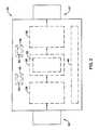
- FIG. 2shows a schematic box diagram of features of an illustrative gas regulating unit according to aspects of the disclosure.
- FIG. 1shows an exploded representation of a gas regulating unit 10 according to the invention, wherein the gas regulating unit 10 of FIG. 1 comprises a valve basic body 11 .
- the gas regulating unit 10further comprises a safety valve 38 and a main gas valve 32 , as shown in FIG. 2 .
- the valve basic body 11 of the gas regulating unit 10comprises three parts, namely a plastic core 12 , a first metallic shell 13 and a second metallic shell 14 .
- the plastic core 12defines a gas inlet chamber 34 and a gas outlet chamber 36 of the gas regulating unit, wherein on the gas inlet chamber 34 there is configured a connecting socket 16 for a gas supply line and on the gas outlet chamber 36 there is configured a connecting socket 17 for a gas evacuation line.
- the first metallic shell 13encloses the plastic core 12 , at least in sections, on a top side of the same.
- the second metallic shell 14encloses the plastic core 12 , likewise at least in sections, on a bottom side of the same.
- a diaphragm 15which at least for the main gas valve delimits a drive chamber 40 , in which a servo pressure prevails.
- the diaphragm 15which is positioned between the bottom side of the plastic core 12 and the second metallic shell 15 by which the plastic core 12 is enclosed on the bottom side and the second metallic shell 14 jointly delimit at least one drive chamber 40 , in which a servo pressure respective prevails.
- the metallic shells 13 , 14which enclose the plastic core 12 at least in sections, have connecting elements 20 for the actuators or operators 18 , 19 of the safety valve 38 and main gas valve 32 , wherein the operators 18 , 19 preferably take the form of magnets 54 .
- the metallic shells 13 , 14surround the connecting sockets 16 , 17 of the plastic core 12 .
- Fastening elements, by which the gas supply line can be fastened to the connecting socket 16 and the gas evacuation line can be fastened to the connecting socket 17consequently engage on those sections of the metallic shells 13 , 14 which enclose the connecting sockets 16 , 17 .
- the plastic cover 12serves in particular to provide a gas inlet chamber 34 and a gas outlet chamber 36 of the gas regulating unit.
- the metallic shells 13 , 14which enclose the plastic core 12 at least in section, stabilize the plastic core 12 and protect the same from mechanical loads which can act on the plastic core 12 from the outside.
- Fastening devicesby which the gas supply line and the gas evacuation line can be fastened to the connecting sockets 16 , 17 , thus engage on those sections of the metallic shells 13 , 14 which enclose the connecting sockets 16 , 17 .
- the operators 18 , 19are fastened to the connecting elements 20 of the metallic shells 13 , 14 or engage on the same. Mechanical forces are consequently absorbed by the metallic shells 13 , 14 , so that the plastic core 12 is essentially exposed only to loads induced by the gas flow.
- the metallic shells 13 , 14which enclose the plastic core 12 on the top side and the bottom side additionally have connecting elements 21 , at which the two metallic shells 13 , 14 can be connected to each other.
Landscapes
- Engineering & Computer Science (AREA)
- General Engineering & Computer Science (AREA)
- Mechanical Engineering (AREA)
- Valve Housings (AREA)
- Fluid-Driven Valves (AREA)
- Feeding And Controlling Fuel (AREA)
Abstract
Description
- 10 gas regulating unit
- 11 valve basic body
- 12 plastic core
- 13 first metallic shell
- 14 second metallic shell
- 15 diaphragm
- 16 connecting socket
- 17 connecting socket
- 18 operator
- 19 operator
- 20 connecting element
- 21 connecting element
Claims (16)
Applications Claiming Priority (4)
| Application Number | Priority Date | Filing Date | Title |
|---|---|---|---|
| DE102008027796 | 2008-06-11 | ||
| DE200810027796DE102008027796A1 (en) | 2008-06-11 | 2008-06-11 | Gas Regulator |
| DE102008027796.7 | 2008-06-11 | ||
| PCT/EP2009/003659WO2009149822A1 (en) | 2008-06-11 | 2009-05-22 | Gas regulating unit |
Publications (2)
| Publication Number | Publication Date |
|---|---|
| US20110162729A1 US20110162729A1 (en) | 2011-07-07 |
| US9163741B2true US9163741B2 (en) | 2015-10-20 |
Family
ID=41066051
Family Applications (1)
| Application Number | Title | Priority Date | Filing Date |
|---|---|---|---|
| US12/996,905Active2030-04-13US9163741B2 (en) | 2008-06-11 | 2009-05-22 | Gas regulating unit |
Country Status (4)
| Country | Link |
|---|---|
| US (1) | US9163741B2 (en) |
| EP (1) | EP2283263B1 (en) |
| DE (1) | DE102008027796A1 (en) |
| WO (1) | WO2009149822A1 (en) |
Cited By (1)
| Publication number | Priority date | Publication date | Assignee | Title |
|---|---|---|---|---|
| US11168801B2 (en)* | 2018-06-28 | 2021-11-09 | Swagelok Company | Fluid component body and method of making same |
Citations (14)
| Publication number | Priority date | Publication date | Assignee | Title |
|---|---|---|---|---|
| US2649767A (en)* | 1950-12-27 | 1953-08-25 | Milwaukee Gas Specialty Co | Alternating current drop-out means for thermoelectric safety shutoff devices |
| US3000320A (en)* | 1957-07-18 | 1961-09-19 | Ring Sandiford | Pump |
| US3355945A (en)* | 1965-04-23 | 1967-12-05 | Robert B Bishop Inc | Tamper-proof meter enclosure |
| US3407838A (en)* | 1966-01-12 | 1968-10-29 | Grinnell Corp | Plastic lined valve |
| US3731534A (en)* | 1970-11-18 | 1973-05-08 | Rockwell Mfg Co | Housing structure for meters |
| US4558206A (en)* | 1983-09-19 | 1985-12-10 | Ball Randell D | Electric heating apparatus for providing freeze protection for fluid-control devices at well sites |
| US4562857A (en)* | 1983-09-19 | 1986-01-07 | Ball Randell D | Thermal insulation article |
| US4976366A (en)* | 1990-01-10 | 1990-12-11 | Russell Jim L | Underground valve box |
| US20030030024A1 (en) | 2001-08-13 | 2003-02-13 | Robertshaw Controls Company | Encased gas valve control housing having a plastic body and an over-molded seal |
| US20030145891A1 (en)* | 2002-02-01 | 2003-08-07 | Buescher Thomas P. | Fluid flow regulator with restrictor pin |
| US20040163704A1 (en) | 2000-12-29 | 2004-08-26 | Hon Technology Inc. | Gas valve switch structure of gas stove |
| GB2413618A (en) | 2004-04-30 | 2005-11-02 | Wen Chou Chen | Gas control valve assembly |
| DE202008006804U1 (en)* | 2008-05-20 | 2008-08-07 | Bürkert Werke GmbH & Co.KG | Valve |
| US20090092936A1 (en) | 2007-10-03 | 2009-04-09 | Honeywell International Inc. | Pressure regulator with bleed orifice |
Family Cites Families (1)
| Publication number | Priority date | Publication date | Assignee | Title |
|---|---|---|---|---|
| DE20214258U1 (en)* | 2002-09-14 | 2002-11-28 | Shih, Pei Hsi, Taipeh/T'ai-pei | security cabinet |
- 2008
- 2008-06-11DEDE200810027796patent/DE102008027796A1/ennot_activeWithdrawn
- 2009
- 2009-05-22WOPCT/EP2009/003659patent/WO2009149822A1/enactiveApplication Filing
- 2009-05-22USUS12/996,905patent/US9163741B2/enactiveActive
- 2009-05-22EPEP09761385.5Apatent/EP2283263B1/enactiveActive
Patent Citations (16)
| Publication number | Priority date | Publication date | Assignee | Title |
|---|---|---|---|---|
| US2649767A (en)* | 1950-12-27 | 1953-08-25 | Milwaukee Gas Specialty Co | Alternating current drop-out means for thermoelectric safety shutoff devices |
| US3000320A (en)* | 1957-07-18 | 1961-09-19 | Ring Sandiford | Pump |
| US3355945A (en)* | 1965-04-23 | 1967-12-05 | Robert B Bishop Inc | Tamper-proof meter enclosure |
| US3407838A (en)* | 1966-01-12 | 1968-10-29 | Grinnell Corp | Plastic lined valve |
| US3731534A (en)* | 1970-11-18 | 1973-05-08 | Rockwell Mfg Co | Housing structure for meters |
| US4558206A (en)* | 1983-09-19 | 1985-12-10 | Ball Randell D | Electric heating apparatus for providing freeze protection for fluid-control devices at well sites |
| US4562857A (en)* | 1983-09-19 | 1986-01-07 | Ball Randell D | Thermal insulation article |
| US4976366A (en)* | 1990-01-10 | 1990-12-11 | Russell Jim L | Underground valve box |
| US20040163704A1 (en) | 2000-12-29 | 2004-08-26 | Hon Technology Inc. | Gas valve switch structure of gas stove |
| US20030030024A1 (en) | 2001-08-13 | 2003-02-13 | Robertshaw Controls Company | Encased gas valve control housing having a plastic body and an over-molded seal |
| EP1417432A1 (en) | 2001-08-13 | 2004-05-12 | Robertshaw Controls Company | Encased gas valve control housing having a plastic body and an over-molded seal |
| US6793199B2 (en)* | 2001-08-13 | 2004-09-21 | Robertshaw Controls Company | Encased gas valve control housing having a plastic body and an over-molded seal |
| US20030145891A1 (en)* | 2002-02-01 | 2003-08-07 | Buescher Thomas P. | Fluid flow regulator with restrictor pin |
| GB2413618A (en) | 2004-04-30 | 2005-11-02 | Wen Chou Chen | Gas control valve assembly |
| US20090092936A1 (en) | 2007-10-03 | 2009-04-09 | Honeywell International Inc. | Pressure regulator with bleed orifice |
| DE202008006804U1 (en)* | 2008-05-20 | 2008-08-07 | Bürkert Werke GmbH & Co.KG | Valve |
Non-Patent Citations (2)
| Title |
|---|
| English Machine Translation-DE 202008006804, Sep. 29, 2014, Europeon Patent Office, pp. 1-4 claims and 1-4 specification and p. 1 drawings, http://translationportal.epo.org/emtp/translate/?ACTION=description-retrival&COUNTR-attached.* |
| Notification of Transmittal of Translation of the International Preliminary Report on Patentability (Chapter I of Chapter II of the Patent Cooperation Treaty), International Application No. PCT/EP2009/003659, International Filing Date, May 22, 2009, mailed Jan. 20, 2011. |
Cited By (2)
| Publication number | Priority date | Publication date | Assignee | Title |
|---|---|---|---|---|
| US11168801B2 (en)* | 2018-06-28 | 2021-11-09 | Swagelok Company | Fluid component body and method of making same |
| US11965605B2 (en) | 2018-06-28 | 2024-04-23 | Swagelok Company | Fluid component body and method of making same |
Also Published As
| Publication number | Publication date |
|---|---|
| WO2009149822A1 (en) | 2009-12-17 |
| EP2283263A1 (en) | 2011-02-16 |
| EP2283263B1 (en) | 2013-04-17 |
| DE102008027796A1 (en) | 2009-12-17 |
| US20110162729A1 (en) | 2011-07-07 |
Similar Documents
| Publication | Publication Date | Title |
|---|---|---|
| EP1020779B1 (en) | Elastomeric element valve | |
| EP3569921B1 (en) | Poppet type pneumatic valve for inflation system | |
| US20090320931A1 (en) | Universal trim control valve and method of making such a control valve | |
| EP2165921A3 (en) | A fuel tank assembly for a motorcycle and a motorcycle equipped with such a fuel tank assembly | |
| EP3076104B1 (en) | Caulking fixation type power element and expansion valve using the same | |
| CN103574137B (en) | Actuator devices with inner passage | |
| CN102066726A (en) | Installation method and device of cam angle sensor of internal combustion engine | |
| CN101473123A (en) | Pneumatic actuating drive comprising an integrated electropneumatic position adjustment | |
| US20130283815A1 (en) | Integral cooling for servo valve | |
| US9163741B2 (en) | Gas regulating unit | |
| ITMI20071458A1 (en) | WAFER PILOT VALVE | |
| RU2461044C2 (en) | Fluid control device | |
| US4295489A (en) | Pilot-operated back pressure regulator | |
| US6938876B2 (en) | Ball valve with retractable seals and method of replacement thereof | |
| KR100662596B1 (en) | A gas-regulating unit for regulating a gas pressure in a gas-tight tank | |
| CA2454526A1 (en) | Air flow compensation for mold carrier | |
| ITVI20130159A1 (en) | REGOLATION VALVE | |
| JP2018123868A (en) | Gas governor device | |
| US6378548B1 (en) | Varying size diaphragm valve assemblies utilizing diaphragm of uniform size | |
| DK1493480T3 (en) | A filter assembly | |
| CN109630745A (en) | Valve drive system for pneumatically or hydraulically valve | |
| US2982297A (en) | Fluid pressure regulating valve | |
| SE0001952L (en) | Valve arrangements for control of air suspension, valve unit and vehicles fitted with these | |
| AU2011238844B2 (en) | Actuator adapter plate | |
| US11353128B2 (en) | Valve body apparatus for use with fluid valves |
Legal Events
| Date | Code | Title | Description |
|---|---|---|---|
| AS | Assignment | Owner name:HONEYWELL TECHNOLOGIES SARL, SWITZERLAND Free format text:ASSIGNMENT OF ASSIGNORS INTEREST;ASSIGNOR:TRENZ, MILOS;REEL/FRAME:025590/0037 Effective date:20101209 | |
| STCF | Information on status: patent grant | Free format text:PATENTED CASE | |
| MAFP | Maintenance fee payment | Free format text:PAYMENT OF MAINTENANCE FEE, 4TH YEAR, LARGE ENTITY (ORIGINAL EVENT CODE: M1551); ENTITY STATUS OF PATENT OWNER: LARGE ENTITY Year of fee payment:4 | |
| AS | Assignment | Owner name:HONEYWELL PRODUCTS & SOLUTIONS SARL, SWITZERLAND Free format text:ASSIGNMENT OF ASSIGNORS INTEREST;ASSIGNOR:HONEYWELL TECHNOLOGIES SARL ALSO DBA HONEYWELL TECHNOLOGIES S.A.R.L.;REEL/FRAME:057852/0370 Effective date:20180330 Owner name:PITTWAY SARL, SWITZERLAND Free format text:ASSIGNMENT OF ASSIGNORS INTEREST;ASSIGNOR:HONEYWELL PRODUCTS & SOLUTIONS SARL;REEL/FRAME:057862/0254 Effective date:20180627 | |
| MAFP | Maintenance fee payment | Free format text:PAYMENT OF MAINTENANCE FEE, 8TH YEAR, LARGE ENTITY (ORIGINAL EVENT CODE: M1552); ENTITY STATUS OF PATENT OWNER: LARGE ENTITY Year of fee payment:8 |