US9163495B2 - Fracturing system - Google Patents
Fracturing systemDownload PDFInfo
- Publication number
- US9163495B2 US9163495B2US13/807,857US201113807857AUS9163495B2US 9163495 B2US9163495 B2US 9163495B2US 201113807857 AUS201113807857 AUS 201113807857AUS 9163495 B2US9163495 B2US 9163495B2
- Authority
- US
- United States
- Prior art keywords
- sleeve
- fracturing
- tubular part
- formation
- initiating element
- Prior art date
- Legal status (The legal status is an assumption and is not a legal conclusion. Google has not performed a legal analysis and makes no representation as to the accuracy of the status listed.)
- Active, expires
Links
- 230000015572biosynthetic processEffects0.000claimsabstractdescription56
- 239000002184metalSubstances0.000claimsabstractdescription12
- 238000000034methodMethods0.000claimsabstractdescription10
- 230000000977initiatory effectEffects0.000claimsdescription56
- 239000012530fluidSubstances0.000claimsdescription20
- 230000003247decreasing effectEffects0.000claimsdescription15
- 238000004519manufacturing processMethods0.000description12
- 230000004888barrier functionEffects0.000description5
- 239000002253acidSubstances0.000description2
- 238000002955isolationMethods0.000description2
- 238000007789sealingMethods0.000description2
- 239000004568cementSubstances0.000description1
- 239000003795chemical substances by applicationSubstances0.000description1
- 150000001875compoundsChemical class0.000description1
- 230000000694effectsEffects0.000description1
- 239000007789gasSubstances0.000description1
- 239000000463materialSubstances0.000description1
- 230000004048modificationEffects0.000description1
- 238000012986modificationMethods0.000description1
- 239000002245particleSubstances0.000description1
- 230000000149penetrating effectEffects0.000description1
- 230000035515penetrationEffects0.000description1
- 229920000642polymerPolymers0.000description1
- 239000000843powderSubstances0.000description1
- -1powder or particlesChemical class0.000description1
- 230000008569processEffects0.000description1
- XLYOFNOQVPJJNP-UHFFFAOYSA-NwaterSubstancesOXLYOFNOQVPJJNP-UHFFFAOYSA-N0.000description1
- 238000003466weldingMethods0.000description1
Images


Classifications
- E—FIXED CONSTRUCTIONS
- E21—EARTH OR ROCK DRILLING; MINING
- E21B—EARTH OR ROCK DRILLING; OBTAINING OIL, GAS, WATER, SOLUBLE OR MELTABLE MATERIALS OR A SLURRY OF MINERALS FROM WELLS
- E21B43/00—Methods or apparatus for obtaining oil, gas, water, soluble or meltable materials or a slurry of minerals from wells
- E21B43/25—Methods for stimulating production
- E21B43/26—Methods for stimulating production by forming crevices or fractures
- E—FIXED CONSTRUCTIONS
- E21—EARTH OR ROCK DRILLING; MINING
- E21B—EARTH OR ROCK DRILLING; OBTAINING OIL, GAS, WATER, SOLUBLE OR MELTABLE MATERIALS OR A SLURRY OF MINERALS FROM WELLS
- E21B43/00—Methods or apparatus for obtaining oil, gas, water, soluble or meltable materials or a slurry of minerals from wells
- E21B43/02—Subsoil filtering
- E21B43/10—Setting of casings, screens, liners or the like in wells
- E21B43/103—Setting of casings, screens, liners or the like in wells of expandable casings, screens, liners, or the like
- E—FIXED CONSTRUCTIONS
- E21—EARTH OR ROCK DRILLING; MINING
- E21B—EARTH OR ROCK DRILLING; OBTAINING OIL, GAS, WATER, SOLUBLE OR MELTABLE MATERIALS OR A SLURRY OF MINERALS FROM WELLS
- E21B33/00—Sealing or packing boreholes or wells
- E21B33/10—Sealing or packing boreholes or wells in the borehole
- E21B33/12—Packers; Plugs
- E21B33/127—Packers; Plugs with inflatable sleeve
Definitions
- the present inventionrelates to a fracturing system for fracturing a formation surrounding a well tubular structure, comprising a tubular part to be mounted as a part of the well tubular structure, the tubular part being made of metal, an expandable sleeve made of metal, the sleeve having a wall thickness and surrounding the tubular part, a fastening means for connecting the sleeve with the tubular part, and an aperture in the tubular part or the fastening means. Furthermore, the invention relates to a fracturing method for fracturing a formation surrounding a well tubular structure.
- the formationis fractured in order to let oil pass into the wellbore and further on to the production casing.
- these fracturescommonly extend substantially along the casing due to the natural layers in the formation.
- Fractures extending perpendicularly to the casingextend longer into the formation. In this way, they uncover a larger area of the formation filled with oil containing fluid, which leads to a more optimised production than with longitudinal fractures.
- a fracturing system for fracturing a formation surrounding a well tubular structurecomprising:
- the fracturing initiating elementmay project from a surface of the sleeve.
- a fracture initiating element projecting from the surface of the sleeveis meant a position along the surface in which a slope of a tangent to the surface changes from zero to a non-zero value, returns to zero at a peak, and then changes again to a non-zero value of the opposite sign before returning to the original zero slope, the element projecting in this position towards the formation.
- the fracture initiating elementmay at least partly penetrate part of the formation in an expanded condition of the expandable sleeve.
- the expandable sleevemay have an expanded condition in which a contact surface of the sleeve contacts the formation and an unexpanded condition, the fracture initiating element projecting at least in the expanded position from the contact surface into the formation in order to fracture the formation.
- the fracture initiating elementmay be arranged between the fastening means.
- the fracture initiating elementmay comprise a centre part of the sleeve having a decreased wall thickness in relation to another part of the sleeve.
- the fracture initiating elementmay comprise several areas distributed along a circumference of the sleeve, and the areas of the sleeve may have a decreased wall thickness in relation to other areas of the sleeve.
- the fracture initiating elementmay comprise a projection.
- the fracture initiating elementmay comprise a shear plug, a spring-loaded valve or a rupture disc.
- the projectionmay taper away from the tubular part towards the formation.
- the projectionmay be a circumferential projection.
- the sleevemay have a plurality of projections along its circumference to ensure that the projections are arranged in the same circumferential cross-sectional plane of the sleeve.
- the fracture initiating elementmay comprise at least one area having a decreased wall thickness which bursts when it reaches a predetermined pressure.
- the fracturing system as described abovemay further comprise a tool for expanding the expandable sleeve by letting a pressurised fluid through an aperture in the tubular part into a space between the expandable sleeve and the tubular part.
- a valvemay be arranged in the aperture to control the passage of pressurised fluid into the space between the expandable sleeve and the tubular part.
- the sleevemay have two ends made of a different material than a centre part of the sleeve.
- These two endsmay be welded to the centre part, and they may have an inclined surface corresponding to an inclined surface of the centre part of the sleeve.
- the valvemay be a one-way valve or a two-way valve.
- At least one of the fastening meansmay be slidable in relation to the connection part of the tubular part of the annular barrier.
- At least one of the fastening meansmay be fixedly fastened to the tubular part.
- the toolmay have a means for moving the valve from one position to another.
- the toolmay have an isolation device for isolating a first section between an outside wall of the tool and an inside wall of the well tubular structure outside the aperture of the tubular part.
- the isolation device of the toolmay have at least one sealing means for sealing against the inside wall of the well tubular structure on each side of the valve in order to isolate the first section inside the well tubular structure.
- the toolmay have a pressure delivering means for taking in fluid from the borehole and for delivering pressurised fluid to the first section.
- the toolmay have a means for connecting the tool to a drill pipe.
- the toolmay have packers for closing an annular area.
- the inventionfurthermore relates to the use of the fracturing system as described above in a well tubular structure for inserting the structure into a borehole.
- the inventionrelates to a fracturing method for fracturing a formation surrounding a well tubular structure by expanding an expandable sleeve in the fracturing system as described above inside a borehole, the method comprising the steps of:
- the fracturing methodmay comprise the step of expanding the sleeve until the fracture initiating element bursts.
- FIG. 1shows a cross-sectional view of a casing in a wellbore having a horizontal part
- FIG. 2shows a cross-sectional view of a casing in a vertical well
- FIG. 3shows a cross-sectional view of an expanded sleeve creating fractures in the formation
- FIG. 4shows a cross-sectional view of an unexpanded fracturing system
- FIG. 5shows a cross-sectional view of the fracturing system of FIG. 4 in an expanded condition
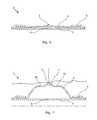
- FIG. 6shows a cross-sectional view of an embodiment of an unexpanded fracturing system
- FIG. 7shows a cross-sectional view of the fracturing system of FIG. 6 in an expanded condition
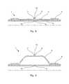
- FIG. 8shows a cross-sectional view of yet another embodiment of an unexpanded fracturing system
- FIG. 9shows a cross-sectional view of the fracturing system of FIG. 8 in an expanded condition
- FIG. 10shows a cross-sectional view of yet another embodiment of an unexpanded fracturing system
- FIG. 11shows a cross-sectional view of the fracturing system of FIG. 10 in its almost fully expanded condition
- FIG. 12shows a cross-sectional view of the fracturing system of FIG. 10 in its fully expanded condition, in which the fracture initiating element burst so to let fluid fracture the formation,
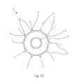
- FIG. 13shows a cross-sectional view transversely through the fracture initiating elements of FIG. 9 .
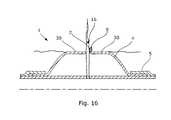
- FIG. 14shows a cross-sectional view of yet another embodiment of an unexpanded fracturing system
- FIG. 15shows a cross-sectional view of the fracturing system of FIG. 14 in an expanded condition
- FIG. 16shows a cross-sectional view of the fracturing system of FIG. 14 in its fully expanded condition in which the fracture initiating element has been released from the sleeve so to let fluid fracture the formation.
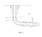
- FIG. 1shows a well having a vertical and a horizontal part.
- formation fractures 11extending perpendicularly to the production casing are shown.
- the production casingis fastened to the formation by means of annular barriers, and the fractures are situated between the expanded annular barriers in the horizontal part.
- the fractures 11are vertical and may also be perpendicular to the natural layers of the formation.
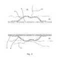
- a well which is only verticalis shown in FIG. 2 .
- the wellhas annular barriers and horizontal fractures, all of which are also perpendicular and transverse to the production casing.
- transverse fracturesboth types of fractures 11 illustrated in FIGS. 1 and 2 , which are perpendicular to the production casing, will be referred to as transverse fractures.
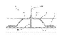
- FIG. 3shows an illustration of an expanded sleeve 4 creating transverse fractures 11 in the formation above the sleeve and longitudinal fractures in the formation below the sleeve.
- longitudinal fracturesare fractures extending along the extension of the production casing.
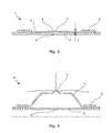
- FIG. 4shows a fracturing system 1 comprising a sleeve 4 with a fracture initiating element 7 .
- the fracture initiating element 7is in this embodiment a part of the sleeve 4 having an decreased wall thickness so that when the sleeve is expanded, as shown in FIG. 5 , the fracture initiating element 7 projects and functions as a notch when pressed towards the formation. In this way, the fracturing process is controlled to ensure that the fractures are transverse instead of longitudinal.
- the fracturing system 1comprises an expandable sleeve 4 and a tubular metal part 3 , both of which are mounted as a part of the well tubular structure 2 when inserting the production casing in the borehole.
- the expandable sleeve 4has a wall thickness t in its unexpanded condition and surrounds the tubular part 3 and is sealingly fastened to the tubular part by means of a fastening means 5 .
- the tubular part 3has at least one aperture 6 functioning as a passage for letting fluid into the space between the sleeve 4 and the tubular part to expand the sleeve.
- the expandable sleeve 4has a fracture initiating element 7 which is a part of the sleeve having a decreased wall thickness, as shown in FIG. 4 .
- the fracture initiating element 7comprises a projection 9 tapering into a circumferential rim.
- the sleeve 4 of FIG. 6is shown in its expanded condition in FIG. 7 in which the part of the sleeve having a decreased thickness projects towards the formation as a projecting part, and the rim arranged on the projecting part having a decreased thickness presses against the formation and increases the notch effect of the projecting part.
- the fracturing initiating elementprojects from a surface of the sleeve.
- a fracture initiating element projecting from the surface of the sleeveis meant a position along the surface in which a slope of a tangent to the surface changes from zero to a non-zero value, returns to zero at a peak, and then changes again to a non-zero value of the opposite sign before returning to the original zero slope, the element projecting in this position from the surface of the sleeve and towards the formation.
- the fracture initiating elementat least partly penetrates part of the formation in an expanded condition of the expandable sleeve. After penetration of part of the fracture initiating element, a contact surface 30 being another part of the sleeve contacts the formation.
- the expandable sleeve 4has a plurality of fracture initiating elements 7 in the form of parts of the sleeve having a decreased wall thickness.
- the sleeve 4has several circular areas having a decreased thickness, and on the outside of the sleeve each fracture initiating element comprises a projection 9 tapering towards a point.
- the sleeve 4 of FIG. 8comprises a plurality of fracture initiating elements 7 in the form of projections 9 arranged on the outside of the sleeve in the same cross-sectional plane of the sleeve transverse to the longitudinal direction of the casing.
- Each projection 9tapers towards a point 16 which is pressed into the formation when the sleeve 4 is expanded, and the point 16 of each projection 9 functions as a notch initiating a fracture transverse to the longitudinal direction of the casing when the sleeve is expanded, as shown in FIG. 9 .
- the aperture 6may have a valve 10 which must be opened before pressurised fluid 12 can be injected into the space between the sleeve 4 and the tubular part 3 in order to expand the sleeve.
- the fracturing system 1has a plurality of fracture initiating elements 7 in the form of areas having a decreased wall thickness.
- the areas having a decreased wall thicknessproject from the outside of the sleeve towards the formation, and when being further expanded, the areas burst, as shown in FIG. 12 .
- the fracture initiating elements 7function as notches creating fractures 11 in the formation, and when they burst, fluid 15 can be injected into the formation wall at a high pressure, thereby fracturing the formation even further. If the fluid 15 comprises acid, the fractures 11 can be enlarged by means of the acid.
- transverse fracturesAs mentioned, it is desirable to have transverse fractures, and by having a plurality of fracture initiating elements 7 in the same cross-sectional plane, controlled transverse fractures are easily made in the same cross-sectional plane transverse to the longitudinal direction of the production casing.
- a more efficient fracturing system 1is provided, controlling the fracturing direction of the fractures.
- FIG. 13a cross-sectional view transverse to the longitudinal extension of the fracturing system through the sleeve and the fracture initiating elements are shown with transverse fractures in the same cross-sectional plane. Furthermore, the fracture elements are shown spaced along the circumference of the sleeve.
- FIG. 14An unexpanded fracturing system in which the fracture initiating element is a shear plug fastened in the wall of the sleeve is shown in the cross-sectional view of FIG. 14 .
- the fracture initiating elementpartly penetrates the formation as shown in FIG. 15 and is releasable from the sleeve when a certain pressure is injected into the aperture 6 so that the fracture initiating element leaves an open hole in the wall of the sleeve.
- fracturing fluidis penetrating the hole in the sleeve wall and further into the fracture in the formation.
- the fracture initiating elementmay be a spring-loaded valve or a rupture disc.
- the fracture initiating elementmay also be a pointed element being welded as part of the wall of the sleeve, and thus the welding connection breaks at a certain fluid pressure injected through the aperture 6 .
- the well tubular structure 2may be the production tubing or casing, or a similar kind of tubing downhole in a well or a borehole.
- the valve 10may be any kind of valve capable of controlling a flow, such as a ball valve, a butterfly valve, a choke valve, a check valve or non-return valve, a diaphragm valve, an expansion valve, a gate valve, a globe valve, a knife valve, a needle valve, a piston valve, a pinch valve or a plug valve.
- a ball valvesuch as a ball valve, a butterfly valve, a choke valve, a check valve or non-return valve, a diaphragm valve, an expansion valve, a gate valve, a globe valve, a knife valve, a needle valve, a piston valve, a pinch valve or a plug valve.
- the expandable tubular metal sleeve 4may be a cold-drawn or hot-drawn tubular structure.
- the fluid used for expanding the expandable sleeve 4may be any kind of well fluid present in the borehole surrounding the tool 20 and/or the well tubular structure 3 .
- the fluidmay be cement, gas, water, polymers or a two-component compound, such as powder or particles, mixing or reacting with a binding or hardening agent.
Landscapes
- Geology (AREA)
- Life Sciences & Earth Sciences (AREA)
- Engineering & Computer Science (AREA)
- Mining & Mineral Resources (AREA)
- Environmental & Geological Engineering (AREA)
- Fluid Mechanics (AREA)
- Physics & Mathematics (AREA)
- General Life Sciences & Earth Sciences (AREA)
- Geochemistry & Mineralogy (AREA)
- Pipe Accessories (AREA)
- Quick-Acting Or Multi-Walled Pipe Joints (AREA)
- Revetment (AREA)
- Tires In General (AREA)
Abstract
Description
- a tubular part to be mounted as a part of the well tubular structure, the tubular part being made of metal,
- an expandable sleeve made of metal, the sleeve having a wall thickness and surrounding the tubular part,
- a fastening means for connecting the sleeve with the tubular part, and
- an aperture in the tubular part or the fastening means, wherein the sleeve has a fracture initiating element.
- placing a tool outside the aperture of the tubular part,
- injecting fluid into the space between the tubular part and the expandable sleeve to expand the sleeve,
- fracturing the formation by expanding the sleeve until the sleeve applies a predetermined pressure on the formation.
Claims (20)
Applications Claiming Priority (4)
| Application Number | Priority Date | Filing Date | Title |
|---|---|---|---|
| EP10167951 | 2010-06-30 | ||
| EP10167951AEP2402554A1 (en) | 2010-06-30 | 2010-06-30 | Fracturing system |
| EP10167951.2 | 2010-06-30 | ||
| PCT/EP2011/061033WO2012001118A1 (en) | 2010-06-30 | 2011-06-30 | Fracturing system |
Publications (2)
| Publication Number | Publication Date |
|---|---|
| US20130098621A1 US20130098621A1 (en) | 2013-04-25 |
| US9163495B2true US9163495B2 (en) | 2015-10-20 |
Family
ID=42633335
Family Applications (1)
| Application Number | Title | Priority Date | Filing Date |
|---|---|---|---|
| US13/807,857Active2032-06-19US9163495B2 (en) | 2010-06-30 | 2011-06-30 | Fracturing system |
Country Status (8)
| Country | Link |
|---|---|
| US (1) | US9163495B2 (en) |
| EP (2) | EP2402554A1 (en) |
| CN (1) | CN102959181B (en) |
| BR (1) | BR112012033293B1 (en) |
| CA (1) | CA2803714C (en) |
| DK (1) | DK2588713T3 (en) |
| RU (1) | RU2572631C2 (en) |
| WO (1) | WO2012001118A1 (en) |
Families Citing this family (10)
| Publication number | Priority date | Publication date | Assignee | Title |
|---|---|---|---|---|
| FR2996247B1 (en)* | 2012-10-03 | 2015-03-13 | Saltel Ind | HYDRAULIC FRACTURING METHOD AND CORRESPONDING EQUIPMENT |
| FR2996248B1 (en)* | 2012-10-03 | 2015-03-13 | Saltel Ind | DEVICE AND METHOD FOR HYDRAULIC FRACTURING |
| US9309758B2 (en)* | 2012-12-18 | 2016-04-12 | Schlumberger Technology Corporation | System and method for determining mechanical properties of a formation |
| US9267368B2 (en)* | 2013-04-29 | 2016-02-23 | Baker Hughes Incorporated | Fracturing multiple zones with inflatables |
| EP2876251A1 (en)* | 2013-11-21 | 2015-05-27 | Welltec A/S | Annular barrier with passive pressure compensation |
| NO3044084T3 (en) | 2013-12-04 | 2018-04-14 | ||
| WO2015117924A2 (en)* | 2014-02-05 | 2015-08-13 | Saltel Industries | Expandable device |
| CN111982614B (en)* | 2019-05-23 | 2023-11-28 | 中国石油天然气股份有限公司 | Seam making device, system and process for simulating real rock displacement experiment process |
| CN114517653B (en)* | 2020-11-20 | 2024-09-17 | 中国石油化工股份有限公司 | Slotted pipe hanging device and composite plugging method |
| RU2765186C1 (en)* | 2021-03-23 | 2022-01-26 | Тарасов Алексей Сергеевич | Formation hydraulic fracturing method (options) and coupling for its implementation |
Citations (21)
| Publication number | Priority date | Publication date | Assignee | Title |
|---|---|---|---|---|
| US2798557A (en) | 1952-05-16 | 1957-07-09 | Exxon Research Engineering Co | Fracturing oil bearing formations |
| US2923358A (en) | 1957-06-03 | 1960-02-02 | Jersey Prod Res Co | Formation fracture detector |
| US3062294A (en) | 1959-11-13 | 1962-11-06 | Gulf Research Development Co | Apparatus for fracturing a formation |
| US3924677A (en)* | 1974-08-29 | 1975-12-09 | Harry Koplin | Device for use in the completion of an oil or gas well |
| US5325923A (en) | 1992-09-29 | 1994-07-05 | Halliburton Company | Well completions with expandable casing portions |
| US5396957A (en) | 1992-09-29 | 1995-03-14 | Halliburton Company | Well completions with expandable casing portions |
| US5425424A (en)* | 1994-02-28 | 1995-06-20 | Baker Hughes Incorporated | Casing valve |
| CN1308705A (en) | 1998-07-01 | 2001-08-15 | 国际壳牌研究有限公司 | Method and tool for fracturing an underground formation |
| US20020195245A1 (en) | 2001-06-20 | 2002-12-26 | Weatherford/Lamb, Inc. | Expandable sand screen for use in a wellbore |
| US20050121203A1 (en)* | 2003-12-08 | 2005-06-09 | Baker Hughes Incorporated | Cased hole perforating alternative |
| US20050161232A1 (en)* | 2004-01-27 | 2005-07-28 | Schlumberger Technology Corporation | Annular Barrier Tool |
| CN1708631A (en) | 2002-09-23 | 2005-12-14 | 哈利伯顿能源服务公司 | Annular isolators for expandable tubulars in wellbores |
| US20060131020A1 (en) | 2004-12-21 | 2006-06-22 | Zupanick Joseph A | Perforating tubulars |
| US20080035345A1 (en) | 2006-05-10 | 2008-02-14 | Kosakewich Darrell S | Method and apparatus for stimulating production from oil and gas wells by freeze-thaw cycling |
| US20080035349A1 (en)* | 2004-04-12 | 2008-02-14 | Richard Bennett M | Completion with telescoping perforation & fracturing tool |
| US20080142219A1 (en)* | 2006-12-14 | 2008-06-19 | Steele David J | Casing Expansion and Formation Compression for Permeability Plane Orientation |
| US20080296024A1 (en)* | 2007-05-29 | 2008-12-04 | Baker Hughes Incorporated | Procedures and Compositions for Reservoir Protection |
| US20080296019A1 (en)* | 2007-06-04 | 2008-12-04 | Johnson Michael H | Completion Method for Fracturing and Gravel Packing |
| WO2009001069A2 (en) | 2007-06-26 | 2008-12-31 | Paul David Metcalfe | Permeability modification |
| US20090044944A1 (en)* | 2007-08-16 | 2009-02-19 | Murray Douglas J | Multi-Position Valve for Fracturing and Sand Control and Associated Completion Methods |
| CN101410588A (en) | 2006-03-28 | 2009-04-15 | 普拉德研究及开发股份有限公司 | Method of fracturing a coalbed gas reservoir |
Family Cites Families (3)
| Publication number | Priority date | Publication date | Assignee | Title |
|---|---|---|---|---|
| NO308424B1 (en)* | 1998-12-10 | 2000-09-11 | Reslink As | Device for tools for setting a radially expandable gasket |
| RU2209970C1 (en)* | 2001-11-27 | 2003-08-10 | Институт горного дела СО РАН | Device for rock breaking by hydraulic fracturing |
| RU2253013C1 (en)* | 2003-12-24 | 2005-05-27 | Институт горного дела Сибирского отделения Российской Академии наук (статус государственного учреждения) | Device for destruction of rocks by hydraulic fracturing |
- 2010
- 2010-06-30EPEP10167951Apatent/EP2402554A1/ennot_activeWithdrawn
- 2011
- 2011-06-30CACA2803714Apatent/CA2803714C/ennot_activeExpired - Fee Related
- 2011-06-30WOPCT/EP2011/061033patent/WO2012001118A1/enactiveApplication Filing
- 2011-06-30CNCN201180032240.4Apatent/CN102959181B/ennot_activeExpired - Fee Related
- 2011-06-30DKDK11730271.1Tpatent/DK2588713T3/enactive
- 2011-06-30BRBR112012033293-7Apatent/BR112012033293B1/ennot_activeIP Right Cessation
- 2011-06-30EPEP11730271.1Apatent/EP2588713B1/ennot_activeNot-in-force
- 2011-06-30USUS13/807,857patent/US9163495B2/enactiveActive
- 2011-06-30RURU2013103498/03Apatent/RU2572631C2/enactive
Patent Citations (22)
| Publication number | Priority date | Publication date | Assignee | Title |
|---|---|---|---|---|
| US2798557A (en) | 1952-05-16 | 1957-07-09 | Exxon Research Engineering Co | Fracturing oil bearing formations |
| US2923358A (en) | 1957-06-03 | 1960-02-02 | Jersey Prod Res Co | Formation fracture detector |
| US3062294A (en) | 1959-11-13 | 1962-11-06 | Gulf Research Development Co | Apparatus for fracturing a formation |
| US3924677A (en)* | 1974-08-29 | 1975-12-09 | Harry Koplin | Device for use in the completion of an oil or gas well |
| US5325923A (en) | 1992-09-29 | 1994-07-05 | Halliburton Company | Well completions with expandable casing portions |
| US5396957A (en) | 1992-09-29 | 1995-03-14 | Halliburton Company | Well completions with expandable casing portions |
| US5425424A (en)* | 1994-02-28 | 1995-06-20 | Baker Hughes Incorporated | Casing valve |
| CN1308705A (en) | 1998-07-01 | 2001-08-15 | 国际壳牌研究有限公司 | Method and tool for fracturing an underground formation |
| US20020195245A1 (en) | 2001-06-20 | 2002-12-26 | Weatherford/Lamb, Inc. | Expandable sand screen for use in a wellbore |
| CN1708631A (en) | 2002-09-23 | 2005-12-14 | 哈利伯顿能源服务公司 | Annular isolators for expandable tubulars in wellbores |
| US20050121203A1 (en)* | 2003-12-08 | 2005-06-09 | Baker Hughes Incorporated | Cased hole perforating alternative |
| US20050161232A1 (en)* | 2004-01-27 | 2005-07-28 | Schlumberger Technology Corporation | Annular Barrier Tool |
| US20080035349A1 (en)* | 2004-04-12 | 2008-02-14 | Richard Bennett M | Completion with telescoping perforation & fracturing tool |
| US20060131020A1 (en) | 2004-12-21 | 2006-06-22 | Zupanick Joseph A | Perforating tubulars |
| US7225872B2 (en) | 2004-12-21 | 2007-06-05 | Cdx Gas, Llc | Perforating tubulars |
| CN101410588A (en) | 2006-03-28 | 2009-04-15 | 普拉德研究及开发股份有限公司 | Method of fracturing a coalbed gas reservoir |
| US20080035345A1 (en) | 2006-05-10 | 2008-02-14 | Kosakewich Darrell S | Method and apparatus for stimulating production from oil and gas wells by freeze-thaw cycling |
| US20080142219A1 (en)* | 2006-12-14 | 2008-06-19 | Steele David J | Casing Expansion and Formation Compression for Permeability Plane Orientation |
| US20080296024A1 (en)* | 2007-05-29 | 2008-12-04 | Baker Hughes Incorporated | Procedures and Compositions for Reservoir Protection |
| US20080296019A1 (en)* | 2007-06-04 | 2008-12-04 | Johnson Michael H | Completion Method for Fracturing and Gravel Packing |
| WO2009001069A2 (en) | 2007-06-26 | 2008-12-31 | Paul David Metcalfe | Permeability modification |
| US20090044944A1 (en)* | 2007-08-16 | 2009-02-19 | Murray Douglas J | Multi-Position Valve for Fracturing and Sand Control and Associated Completion Methods |
Non-Patent Citations (4)
| Title |
|---|
| Chinese Office Action mailed Jan. 29, 2015 in Chinese Application No. 201180032240.4, with partial English Translation (10 pages). |
| International Preliminary Report on Patentability for PCT/EP2011/061033, issued Jan. 8, 2013 6 pages. |
| International Search Report for PCT/EP2011/061033 mailed Aug. 8, 2011. |
| Written Opinion of the International Searching Authority mailed Aug. 8, 2011. |
Also Published As
| Publication number | Publication date |
|---|---|
| CN102959181A (en) | 2013-03-06 |
| WO2012001118A1 (en) | 2012-01-05 |
| CN102959181B (en) | 2016-03-30 |
| BR112012033293A2 (en) | 2016-11-22 |
| CA2803714A1 (en) | 2012-01-05 |
| CA2803714C (en) | 2018-11-27 |
| BR112012033293B1 (en) | 2020-05-12 |
| EP2588713A1 (en) | 2013-05-08 |
| DK2588713T3 (en) | 2016-06-13 |
| US20130098621A1 (en) | 2013-04-25 |
| RU2013103498A (en) | 2014-08-10 |
| RU2572631C2 (en) | 2016-01-20 |
| EP2402554A1 (en) | 2012-01-04 |
| EP2588713B1 (en) | 2016-03-09 |
Similar Documents
| Publication | Publication Date | Title |
|---|---|---|
| US9163495B2 (en) | Fracturing system | |
| US10202819B2 (en) | Annular barrier and annular barrier system | |
| US10066453B2 (en) | Self locking plug seat, system and method | |
| US7513313B2 (en) | Bottom plug for forming a mono diameter wellbore casing | |
| US9404335B2 (en) | Annular barrier system with flow lines | |
| US9206666B2 (en) | Annular barrier with external seal | |
| US10024136B2 (en) | Systems and methods for fluid communication with an earth formation through cement | |
| EP3500719B1 (en) | Degradable pump in shoe | |
| US9080422B2 (en) | Liner wiper plug with bypass option | |
| EP3020912A1 (en) | Annular barrier with closing mechanism | |
| US10815749B2 (en) | Loosely assembled wellbore isolation assembly | |
| EP2644821A1 (en) | An annular barrier having a flexible connection | |
| EP2436874B1 (en) | Drill pipe | |
| US7971640B2 (en) | Method and device for setting a bottom packer | |
| US11371311B2 (en) | Annular barrier with press connections | |
| US20140076446A1 (en) | Fluid flow impedance system |
Legal Events
| Date | Code | Title | Description |
|---|---|---|---|
| AS | Assignment | Owner name:WELLTEC A/S, DENMARK Free format text:ASSIGNMENT OF ASSIGNORS INTEREST;ASSIGNORS:HALLUNDBAEK, JORGEN;HAZEL, PAUL;SIGNING DATES FROM 20121204 TO 20121212;REEL/FRAME:029547/0745 | |
| STCF | Information on status: patent grant | Free format text:PATENTED CASE | |
| AS | Assignment | Owner name:WELLTEC OILFIELD SOLUTIONS AG, SWITZERLAND Free format text:ASSIGNMENT OF ASSIGNORS INTEREST;ASSIGNOR:WELLTEC A/S;REEL/FRAME:047724/0079 Effective date:20181008 | |
| MAFP | Maintenance fee payment | Free format text:PAYMENT OF MAINTENANCE FEE, 4TH YEAR, LARGE ENTITY (ORIGINAL EVENT CODE: M1551); ENTITY STATUS OF PATENT OWNER: LARGE ENTITY Year of fee payment:4 | |
| AS | Assignment | Owner name:WELLTEC OILFIELD SOLUTIONS AG, SWITZERLAND Free format text:CHANGE OF ADDRESS;ASSIGNOR:WELLTEC OILFIELD SOLUTIONS AG;REEL/FRAME:048853/0289 Effective date:20190401 | |
| MAFP | Maintenance fee payment | Free format text:PAYMENT OF MAINTENANCE FEE, 8TH YEAR, LARGE ENTITY (ORIGINAL EVENT CODE: M1552); ENTITY STATUS OF PATENT OWNER: LARGE ENTITY Year of fee payment:8 |