US9162350B2 - Robust nose torque-limiting device - Google Patents
Robust nose torque-limiting deviceDownload PDFInfo
- Publication number
- US9162350B2 US9162350B2US13/191,203US201113191203AUS9162350B2US 9162350 B2US9162350 B2US 9162350B2US 201113191203 AUS201113191203 AUS 201113191203AUS 9162350 B2US9162350 B2US 9162350B2
- Authority
- US
- United States
- Prior art keywords
- torque
- shank
- limiting driver
- spring
- disposable
- Prior art date
- Legal status (The legal status is an assumption and is not a legal conclusion. Google has not performed a legal analysis and makes no representation as to the accuracy of the status listed.)
- Active, expires
Links
Images


Classifications
- B—PERFORMING OPERATIONS; TRANSPORTING
- B25—HAND TOOLS; PORTABLE POWER-DRIVEN TOOLS; MANIPULATORS
- B25B—TOOLS OR BENCH DEVICES NOT OTHERWISE PROVIDED FOR, FOR FASTENING, CONNECTING, DISENGAGING OR HOLDING
- B25B23/00—Details of, or accessories for, spanners, wrenches, screwdrivers
- B25B23/14—Arrangement of torque limiters or torque indicators in wrenches or screwdrivers
- B25B23/142—Arrangement of torque limiters or torque indicators in wrenches or screwdrivers specially adapted for hand operated wrenches or screwdrivers
- A—HUMAN NECESSITIES
- A61—MEDICAL OR VETERINARY SCIENCE; HYGIENE
- A61B—DIAGNOSIS; SURGERY; IDENTIFICATION
- A61B17/00—Surgical instruments, devices or methods
- A61B17/56—Surgical instruments or methods for treatment of bones or joints; Devices specially adapted therefor
- A61B17/58—Surgical instruments or methods for treatment of bones or joints; Devices specially adapted therefor for osteosynthesis, e.g. bone plates, screws or setting implements
- A61B17/88—Osteosynthesis instruments; Methods or means for implanting or extracting internal or external fixation devices
- A61B17/8875—Screwdrivers, spanners or wrenches
- A—HUMAN NECESSITIES
- A61—MEDICAL OR VETERINARY SCIENCE; HYGIENE
- A61B—DIAGNOSIS; SURGERY; IDENTIFICATION
- A61B90/00—Instruments, implements or accessories specially adapted for surgery or diagnosis and not covered by any of the groups A61B1/00 - A61B50/00, e.g. for luxation treatment or for protecting wound edges
- A61B90/03—Automatic limiting or abutting means, e.g. for safety
- B—PERFORMING OPERATIONS; TRANSPORTING
- B25—HAND TOOLS; PORTABLE POWER-DRIVEN TOOLS; MANIPULATORS
- B25B—TOOLS OR BENCH DEVICES NOT OTHERWISE PROVIDED FOR, FOR FASTENING, CONNECTING, DISENGAGING OR HOLDING
- B25B15/00—Screwdrivers
- B25B15/02—Screwdrivers operated by rotating the handle
- B25B15/04—Screwdrivers operated by rotating the handle with ratchet action
- B—PERFORMING OPERATIONS; TRANSPORTING
- B25—HAND TOOLS; PORTABLE POWER-DRIVEN TOOLS; MANIPULATORS
- B25B—TOOLS OR BENCH DEVICES NOT OTHERWISE PROVIDED FOR, FOR FASTENING, CONNECTING, DISENGAGING OR HOLDING
- B25B23/00—Details of, or accessories for, spanners, wrenches, screwdrivers
- B25B23/14—Arrangement of torque limiters or torque indicators in wrenches or screwdrivers
- B25B23/141—Mechanical overload release couplings
- B—PERFORMING OPERATIONS; TRANSPORTING
- B25—HAND TOOLS; PORTABLE POWER-DRIVEN TOOLS; MANIPULATORS
- B25B—TOOLS OR BENCH DEVICES NOT OTHERWISE PROVIDED FOR, FOR FASTENING, CONNECTING, DISENGAGING OR HOLDING
- B25B23/00—Details of, or accessories for, spanners, wrenches, screwdrivers
- B25B23/14—Arrangement of torque limiters or torque indicators in wrenches or screwdrivers
- B25B23/142—Arrangement of torque limiters or torque indicators in wrenches or screwdrivers specially adapted for hand operated wrenches or screwdrivers
- B25B23/1422—Arrangement of torque limiters or torque indicators in wrenches or screwdrivers specially adapted for hand operated wrenches or screwdrivers torque indicators or adjustable torque limiters
- B25B23/1427—Arrangement of torque limiters or torque indicators in wrenches or screwdrivers specially adapted for hand operated wrenches or screwdrivers torque indicators or adjustable torque limiters by mechanical means
- A61B2019/301—
- A—HUMAN NECESSITIES
- A61—MEDICAL OR VETERINARY SCIENCE; HYGIENE
- A61B—DIAGNOSIS; SURGERY; IDENTIFICATION
- A61B90/00—Instruments, implements or accessories specially adapted for surgery or diagnosis and not covered by any of the groups A61B1/00 - A61B50/00, e.g. for luxation treatment or for protecting wound edges
- A61B90/03—Automatic limiting or abutting means, e.g. for safety
- A61B2090/031—Automatic limiting or abutting means, e.g. for safety torque limiting
Definitions
- This disclosurerelates to a medical use driver tool and, in particular, to a torque-limiting driver that disengages at a predefined torque limit.
- Torque-limiting driversare widely used throughout the medical industry. These torque-limiting drivers have a factory pre-set torque to ensure the accuracy and toughness required to meet a demanding surgical environment.
- Reusable driversrequire constant recalibration to ensure that the driver is imparting the precise amount of torque. Recalibration is a cumbersome task but must be done routinely.
- Disposable driversare an easy to use and reliable alternative to the reusable drivers.
- a medical devicesuch as an implant, for example, is packaged with a disposable driver designed to the implant's specifications. Once the driver has been used, it can be discarded. Thus, a surgeon can have complete confidence that the disposable driver, packaged with an implant, will impart the precise amount of torque.
- the torque requirementis different for different operations and for different implants. For example, applications may include those in the field of orthopedic surgery, construction and emplacement of implants, etc.
- ris the vector representing the distance and direction from an axis of a fastener to a point where the force is applied and F is the force vector acting on the driver.
- Torquehas dimensions of force times distance and the SI unit of torque is the Newton meter (N m).
- the joulewhich is the SI unit for energy or work, is also defined as an N m, but this unit is not used for torque. Since energy can be thought of as the result of force times distance, energy is always a scalar whereas torque is force cross-distance and so is a vector-valued quantity.
- Other non-SI units of torqueinclude pound-force-feet, foot-pounds-force, ounce-force-inches, meter-kilograms-force, inch-ounces or inch pounds.
- a disposable torque-limiting driverin accordance with the present disclosure, has a handle, a cylindrical body and a work-piece engaging tip.
- the torque-limiting assemblyincludes an upper cylindrical shank and a lower cylindrical shank.
- the upper cylindrical shank and the lower cylindrical shankhave a plurality of teeth.
- the teethhave a vertical face, an inclined face and a substantially flat peak.
- the inclined faceis defined by a first radius of curvature that transitions to the substantially flat peak.
- the teethare spaced circumferentially and spiral around the upper cylindrical shank and a lower cylindrical shank.
- the teeth of the upper cylindrical shank and the lower cylindrical shankengage for relative rotation when the handle is turned and disengage when a predetermined value of torque is exceeded.
- a round square implementationprovides a range of use over predetermined cycles of up to almost 150 inch pounds rotations without cracking the plastic nose cone.
- a square engagement with radiuses corners having radii between about 0.1482 and about 0.1638 inchesare optimal.
- a square engagement with radiuses corners having radii between about 0.1292304 and about 0.1716 inchesare optimal.
- a square engagement with radiuses corners having radiiis between about 0.1266 and about 0.1794 inches is optimal.
- a torque drivercapable of transferring high torque with a spring having a spring constant (also referred to as a force constant) which exerts a greater force in an initial (rest) state via a multiple washer bearing interface.
- a single washer interface with end of springmay have a tendency to grip or bind spring and washer; a multiple washer interface provides a bearing surface between spring and remote second washer. Elimination or reduction of binding or gripping between washer and spring may provide a smoother rotation.
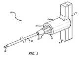
- FIG. 1is a perspective view of a driver in accordance with the present disclosure.
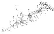
- FIG. 2is an exploded view of a driver in accordance with the present disclosure.
- FIG. 3is a vertical cross sectional view of a driver in accordance with the present disclosure.
- FIG. 4is a horizontal cross sectional view of a driver in accordance with the present disclosure.
- FIG. 5is a perspective view of an upper shank in accordance with the present disclosure.
- FIG. 6is a profile of a tooth from a clutch assembly in accordance with the present disclosure.
- FIG. 7is a perspective view of the teeth from a clutch assembly in accordance with the present disclosure.
- FIG. 8is a top view of the teeth from a clutch assembly in accordance with the present disclosure.
- FIG. 9is a partial exploded view of the nose region of FIG. 2 .
- FIG. 10is an exploded view of a driver in accordance with the present disclosure.
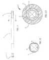
- FIG. 11is shaft in accordance with the present disclosure.
- FIG. 12is a cross sectional view at line A-A of FIG. 11 in accordance with the present disclosure.
- FIG. 13is a front view of the nose of FIG. 10 in accordance with the present disclosure.
- Appendices “A-1” through “A-3”show comparative test results with various driver geometries.
- Appendices “B-1” and “B-2”show comparative test results of round square configurations with about 13 revolutions, using a single washer and about 11 revolutions using two adjacent washers.
- the torque-limiting driver 100has a generally T-shaped handle.
- the T-shaped handleincludes arms 4 at one end an axially extending generally hollow cylindrical body 6 , a cap 2 that covers the same end of the T-shaped handle and a cylindrical end 18 opposite the T-shaped handle on the cylindrical body 6 .
- the cap 2may be snap-fitted to the cylindrical body 6 , or may be welded, or attached by any equivalent thereof and the body is preferably molded from a plastic or other economical equivalents.
- a lower shank 700that has and annularly tapering body and a nose cone 8 along its length.
- the lower shank 700may have a plurality of support flanges 10 that add strength while saving material.
- the lower shank 700tapers to a drive socket 9 at the end of the nose cone 8 molded to engage a shaft 14 .
- the shaft 14maybe substantially linear with a proximal end that mates with said drive socket.
- the shaft 14may be hexagonal or cylindrical in transverse cross-sectional shape and is provided, at one end, with a work piece-engaging distal tip 12 , adapted for engagement with an associated work-piece, such as a fastener or the like.
- the work piece-engaging distal tip 12is shown to be a hex wrench, but could be a screwdriver, wrench, or any other tool or medical tool arrangement.
- the lower shank 700has a plurality of teeth 82 arranged in a crown gear formation, a circumferential rim 31 extending radially outwardly and an internally threaded axial bore.
- FIG. 2is an exploded view of the driver 100 .
- the clutch assemblyincludes an upper shank 800 for forcibly engaging the lower shank 700 .
- the upper shank 800has a bottom face that has teeth 82 arranged in a crown gear formation and an annular flange or circumferential rim 83 extending radially outwardly.
- the upper shank 800includes an annular body or outer cylindrical shank 84 , an axial bore 92 through an inner shank 86 .
- the inner shank 86 and outer shank 84are connected via inner supports 88 , leaving the upper shank 800 substantially hollow with internal spaces 90 on a top face.
- the upper shank 800also includes at least one recess 80 on the side of the outer shank.
- the recess 80is provided as a cylindrical cut, relief or recess into the side of the outer shank and maybe provided as a square or rectangular cut or the cut may have a slanted side or sides relative to the axis of the upper shank 800 as shown in FIG. 2 .
- the shaft 14 at its proximal endforms drive connection 16 which is received into the drive socket 9 of the lower shank 700 .
- a washer(not detailed in the implementation) may be provided between the circumferential rim 31 of the lower shank 700 and a circumferential flange 30 extending radially inward within the hollow of the cylindrical body 6 .
- the circumferential rim 31 of the lower shank 700may be provided flush against circumferential flange 30 of the cylindrical body 6 .
- Drive socket 9 and the connection 16are shown having corresponding cross sectional shape.
- the hexagonal shapeprovides multiple stops and surface area to facilitate consistent operation over the anticipated use profile without significant wiggle or loosening of the shaft 14 from the drive socket 9 .
- a use profileincludes, but is not limited to, such factors as required lbf (load) or inch pounds of torque, number of uses, cycle time, material nose cone 8 is formed of and material forming shaft 14 .
- the opposite side of the circumferential flange 30receives the circumferential rim 83 of the upper shank 800 allowing the teeth 82 of the lower shank 700 to engage the teeth 82 of the upper shank 800 when a torque is applied.
- a protrusion 85mates with the recess 80 of the upper shank 800 .
- FIG. 3 and FIG. 4are cross sectional views that best illustrate the protrusion 85 in relation with the recess 80 .
- the protrusion 85extends inward in a radial fashion and has a length along the axis of the cylindrical body 6 for relative moveable engagement within the recess 80 . This engagement provides a locking mechanism of the shaft 14 relative to the T-shaped handle via the upper shank when pressure is applied across the lower shank 700 and the upper shank 80 .
- the recess 80is provided circumferentially wider than the protrusion 85 for allowing the cylindrical body 6 and the T-shaped handle to rotate in reverse a predetermined distance from a locked position without subsequent reverse rotation of the work piece-engaging tip 12 .
- the at least one recess 80 and at least one protrusion 85lock the T-shaped in one direction providing the necessary torque to drive a fastener and allow for a predetermined amount of reverse rotation before unscrewing the fastener.
- a washer 20is provided between the upper shank 800 and the spring 22 .
- the washertransfers pressure from the spring 22 over the top face of the upper shank 800 .
- a cup washer 24 and a locking fastener 26hold the spring 22 in a compressed state.
- the locking fastener 26 Ahas a fastener head 26 B and has a threading 28 that engages a complementary threading within an axial bore 72 of the lower shank 700 .
- the spring 22 and the locking fastener 26 Aprovide the proper tensioning and biasing for the clutch assembly and, generally, the locking fastener 26 A is adjustable to provide proper tension and calibration.
- tooth 82Formed on the top face of the lower shank 700 and the bottom face of the upper shank 800 are the plurality of teeth 82 that forcibly engage to impart torque from the T-shaped handle to the work piece when a torque is applied.
- tooth 82has an inclined face 66 that smoothly transitions to a substantially flat peak 60 , via a first radius of curvature 64 .
- the substantially flat peak 60subsequently transitions smoothly, via a second radius of curvature, to a vertical face 68 that is substantially parallel to the axis of the lower shank 700 and the upper shank 800 .
- the first radius of curvatureis typically much larger than the second radius of curvature.
- the teeth 82are circumferentially spaced in a crown gear formation of the top face and bottom face of the lower shank 700 and the upper shank 800 respectively.
- the teeth 82are also preferably configured in a spiral formation, best shown in FIG. 7 .
- Each face of the lower shank 700 and the upper shank 800has an inner radius and an outer radius and the teeth 82 spiral around the inner radius resulting in a larger tooth detail when viewing the tooth from the outer radius relative to the tooth detail when viewing the tooth from the inner radius.
- the spiral configuration of the teeth 82can also be defined as having a longer inclined face 66 at the edge of the tooth on or near the outer radius relative to the inclined face 66 at the edge of the tooth on or hear the inner radius of the lower shank 700 and the upper shank 800 . Results have shown that teeth arranged in a spiral configuration provide an increased reliability and precision in torque consistency when compared to their non-spiral counterparts.
- the substantially flat peak 60 of the teeth 82can be as wide at the inner radius as they are at the outer radius. Alternatively, the substantially flat peak 60 may be wider at the outer radius and taper toward the inner radius.
- the vertical faces 68 of the teeth 82 of the lower shank 700 and the upper shank 800respectively engage when a torque is applied to prevent relative rotation of the lower shank 700 and the upper shank 800 in one direction.
- the inclined faces 66engage to accommodate relative rotation of the lower shank 700 and the upper shank 800 in an opposite direction.
- the extent to which the locking screw 26 is threaded into the axial bore 72 of the lower shank 700controls the amount of compression or preload on the spring 22 which, subsequently, controls the limiting torque required to effect relative rotation of the lower shank 700 and the upper shank 800 . If the locking screw 26 is threaded deeply into the lower shank 700 , a higher torque will be required to disengage the teeth 82 of the lower shank 700 and the upper shank 800 than if locking screw 26 was threaded into the lower shank 700 relatively shallow.
- the shaft 14will rotate with the cylindrical body 6 and T-shaped handle until a predetermined torque is reached.
- a biasing force exerted by the spring 22is overcome, allowing an inclined face 66 of the upper shank 800 to slide up a respective inclined face 66 of the lower shank 700 , subsequently snapping the teeth 82 of the lower shank 700 into engagement behind a next tooth of the upper shank 800 .
- This snapping soundis typically an audible indication to a user that a predetermined torque has been reached.
- the T-shaped handlerotates in reverse a predetermined distance from a locked position without subsequent reverse rotation of the work piece-engaging tip 12 .
- the driver 100will operate as a standard driver with no torque-limiting feature since the engaging vertical face 68 will force relative rotation of the lower shank 700 and the upper shank 800 in the opposite direction without any torque-limiting feature.
- the disposable torque-limiting driver of the present disclosurepreferably imparts torques on the order of about 1 ounce inch to 100 inch ounces. Torques of this magnitude can be utilized in precision high torque environments such as the installation of dental, joint, vertebral implants and the like. Typically, the torque requirement is different for different operations and for different implants. Therefore, in some instances, the torques maybe around 1 inch pounds. In other instances, the predetermined torque maybe at least 30 inch pounds and yet other instances, at least 60 inch pounds, depending on an implant's specifications.
- a torque-limiting driversuch as driver 100
- driver 100may be prepackaged with an implant provided for one-time use. Such an instance insures that the driver imparts the required amount of torque and has not been worn in or dulled by overuse.
- the driver 100may be reusable.
- the shaft 14may be interchangeably fixed relative to the nose cone 8 for the accommodation of multiple work piece engaging tips 12 .
- the handle of the driveris not limited to a T-shape and may be provided in any other suitable configuration.
- the torque-limiting driver 200generally includes a handle.
- the handle 2includes arms 4 at one end an axially extending generally hollow cylindrical body 6 , a cap 2 that covers the same end of the T-shaped handle and a cylindrical end 18 opposite the T-shaped handle on the cylindrical body 6 .
- the cap 2may be snap-fitted to the cylindrical body 6 , or may be welded, or attached by any equivalent thereof and the body is preferably molded from a plastic or other economical equivalents.
- the lower shank 700that has and annularly tapering body and a nose cone 8 along its length.
- the lower shank 700may have a plurality of support flanges 10 that add strength while saving material.
- the lower shank 700tapers to an axial drive socket 9 ′ at the end of the nose cone 8 molded of a non-metal material such as a plastic, polymer, resin including but not limited to (plastics, resins, polymers, imides, fluoropolymers, thermoplastic polymers, thermosetting plastics, and the like as well as blends or mixtures thereof) to engage a shaft 14 .
- the shaft 14 drive connection 16 ′is rounded square in transverse cross-sectional shape (see FIGS.
- the shaft 14is substantially round in cross section.
- the drive connection 16 ′is generally square but has rounded corners 95 connecting substantially flat sides 97 . Testing has demonstrated that eliminating hard corners between the walls of the square cross section drive connection 16 ′ to the drive socket 9 ′ of lower shank 700 more evenly distributes the force applied thereto and substantially reduces, deformation, bending, breaking, and/or cracking of the non-metal nose cone 8 region of the drive socket 9 ′ at high load (lbf) and/or inch pounds over time as compared to other geometries of drive socket and drive connection as shown in Appendix “A”.
- the round square implementationprovides a range of use over predetermined cycles of up to almost 150 inch pounds. In some implementations the round square implementation provides a range of use over predetermined cycles of between at least about 10 and about 140 inch pounds.
- the round square cross section of the drive connection 16 ′ and drive socket 9 ′have a more robust connection, compared to, triangle or hexagonal and does not “strip”, deform or spin in the drive socket as readily as shafts and drive sockets with hexagonal or triangular cross sections.
- the radii of about 0.156 inches of the catches 99correspond to the rounded corners 95 of the drive connection 16 ′.
- the drive socket 9 ′ of the nose 8is generally square but has rounded corners 95 connecting substantially flat sides 97 .
- the drive socket 9 ′ in cross sectionhas four substantially planar walls; four arched corners (the catches 99 ) and each catch 99 with a preselected radius to distribute the load caused by turning shaft 14 at a predetermined torque over a predetermined number of rotations without cracking the plastic nose cone 8 material that surrounds the drive socket to a point of failure.
- the optimal range of radii to achieve even (as in even load) repetitive rotationscan be selected to correspond to the torque requirements of a particular driver. In some implementations the optimal radii is between about 0.1482 and about 0.1638 inches. In some implementations the optimal radii is between about 0.1292304 and about 0.1716 inches. In some implementations the optimal radii is between about 0.1266 and about 0.1794 inches.
- the lower shank 700has a plurality of teeth arranged in a crown gear formation, a circumferential rim 31 extending radially outwardly and an internally threaded fastener bore.
- FIG. 10is an exploded view of the driver 200 .
- the clutch assemblyincludes an upper shank 800 for forcibly engaging the lower shank 700 .
- the upper shank 800has a bottom face that has teeth arranged in a crown gear formation and an annular flange or circumferential rim extending radially outwardly.
- forceis applied across lower shank 700 and upper shank 800 via spring 22 within cylindrical body 6 .
- washer 20 and washer 21are provided between upper shank 800 and spring 22 .
- Washer 20 and washer 21transfer pressure from spring 22 over the top face of upper shank 800 .
- shoulder washer 25 and a fastener 26 A fastener head 26 Bhold spring 22 in a relatively compressed state.
- the fasteneris threaded 28 and said threads engage with the internally threaded fastener bore inside of the lower shank 700 .
- driver 200 capable of transferring higher torquemay be provided with spring 22 having a greater spring constant (i.e., force constant) or otherwise be calibrated with spring 22 exerting greater forces in an initial (rest) state.
- spring 22having a greater spring constant (i.e., force constant) or otherwise be calibrated with spring 22 exerting greater forces in an initial (rest) state.
- a more robust spring 22may be used when adding washer 20 and washer 21 at the end of said spring nearest said upper shank 800 , in such instance although spring 22 may have a tendency to grip relative to washer 21 the bearing surface between washer 20 and washer 21 provides for smooth rotation.
- Appendix “B”provides test results showing that an increased load may be achieved when using a multi-washer ( 21 and 20 ) system as opposed to a single washer ( 20 or 21 ).
- a drive socket 9 ′which in cross section has four substantially planar walls; four arched corners (the catches 99 ) and each catch 99 with a preselected radius to distribute the load caused by turning shaft 14 at a predetermined torque over a predetermined number of rotations without cracking or otherwise damaging the non-metal nose cone 8 material that surrounds the drive socket to a point of failure.
- a more robust spring 22increases the probability of a friction grip relative to washer 21 .
- Provision of additional washer 20preserves at least one free-spinning structure between the distal end of the spring 22 and upper shank 800 .
- the shoulder washer 27 and washer 25replace the cup washer 24 . testing shows that a cup washer, such as that shown in FIGS. 2 and 3 may over time deform, indent, bend, break fail or partially fail from use and the pressure excreted thereon by the fastener head 26 B against the cup washer 24 .
- the shoulder washer 27 fastener head 26 B interactionreduce such failure or deformation.
- washer 32maybe provided between circumferential rim 31 of lower shank 700 and circumferential flange 30 extending radially inward within the hollow of cylindrical body 6 . Washer 32 may be of a polymer or other material having low coefficient of friction. Alternatively, circumferential rim 31 of lower shank 700 may be provided flush against circumferential flange 30 of cylindrical body 6 .
- each physical element disclosedshould be understood to encompass a disclosure of the action which that physical element facilitates.
Landscapes
- Health & Medical Sciences (AREA)
- Engineering & Computer Science (AREA)
- Surgery (AREA)
- Life Sciences & Earth Sciences (AREA)
- Mechanical Engineering (AREA)
- Orthopedic Medicine & Surgery (AREA)
- Animal Behavior & Ethology (AREA)
- Biomedical Technology (AREA)
- Heart & Thoracic Surgery (AREA)
- Medical Informatics (AREA)
- Molecular Biology (AREA)
- General Health & Medical Sciences (AREA)
- Public Health (AREA)
- Veterinary Medicine (AREA)
- Nuclear Medicine, Radiotherapy & Molecular Imaging (AREA)
- Pathology (AREA)
- Oral & Maxillofacial Surgery (AREA)
- Details Of Spanners, Wrenches, And Screw Drivers And Accessories (AREA)
- Surgical Instruments (AREA)
Abstract
Description
τ=r×F
Claims (13)
Priority Applications (2)
| Application Number | Priority Date | Filing Date | Title |
|---|---|---|---|
| US13/191,203US9162350B2 (en) | 2010-07-28 | 2011-07-26 | Robust nose torque-limiting device |
| US14/856,369US10219853B2 (en) | 2010-07-28 | 2015-09-16 | Robust nose torque-limiting device |
Applications Claiming Priority (3)
| Application Number | Priority Date | Filing Date | Title |
|---|---|---|---|
| US36851910P | 2010-07-28 | 2010-07-28 | |
| US201161463548P | 2011-02-18 | 2011-02-18 | |
| US13/191,203US9162350B2 (en) | 2010-07-28 | 2011-07-26 | Robust nose torque-limiting device |
Related Child Applications (1)
| Application Number | Title | Priority Date | Filing Date |
|---|---|---|---|
| US14/856,369ContinuationUS10219853B2 (en) | 2010-07-28 | 2015-09-16 | Robust nose torque-limiting device |
Publications (2)
| Publication Number | Publication Date |
|---|---|
| US20120198972A1 US20120198972A1 (en) | 2012-08-09 |
| US9162350B2true US9162350B2 (en) | 2015-10-20 |
Family
ID=46676203
Family Applications (3)
| Application Number | Title | Priority Date | Filing Date |
|---|---|---|---|
| US13/191,203Active2034-07-14US9162350B2 (en) | 2010-07-28 | 2011-07-26 | Robust nose torque-limiting device |
| US13/983,552Active2035-03-06US9877764B2 (en) | 2011-02-18 | 2012-02-16 | Robust nose torque-limiting device |
| US14/856,369Active2032-12-11US10219853B2 (en) | 2010-07-28 | 2015-09-16 | Robust nose torque-limiting device |
Family Applications After (2)
| Application Number | Title | Priority Date | Filing Date |
|---|---|---|---|
| US13/983,552Active2035-03-06US9877764B2 (en) | 2011-02-18 | 2012-02-16 | Robust nose torque-limiting device |
| US14/856,369Active2032-12-11US10219853B2 (en) | 2010-07-28 | 2015-09-16 | Robust nose torque-limiting device |
Country Status (4)
| Country | Link |
|---|---|
| US (3) | US9162350B2 (en) |
| EP (1) | EP2675594B1 (en) |
| CA (1) | CA2825095C (en) |
| WO (1) | WO2012112812A2 (en) |
Cited By (13)
| Publication number | Priority date | Publication date | Assignee | Title |
|---|---|---|---|---|
| US20130305889A1 (en)* | 2011-02-18 | 2013-11-21 | Eca Medical Instruments | Robust nose torque-limiting device |
| US20150122091A1 (en)* | 2013-11-01 | 2015-05-07 | Zhongshan Obo Packaging Material Products Co., Ltd. | Type adjustable torque wrench and the use method thereof |
| US20150321326A1 (en)* | 2013-01-23 | 2015-11-12 | Eca Medical Instruments | In-line disposable torque limiting device suitable for power drive |
| US20160354132A1 (en)* | 2014-04-01 | 2016-12-08 | Eca Medical Instruments | Modular clutch assembly |
| US20160354906A1 (en)* | 2014-04-01 | 2016-12-08 | Eca Medical Instruments | Fortified high torque device |
| US9775702B2 (en) | 2010-03-10 | 2017-10-03 | Smith & Nephew, Inc. | Composite interference screws and drivers |
| WO2017151936A3 (en)* | 2016-03-04 | 2017-10-12 | DePuy Synthes Products, Inc. | Surgical torque limiting locking cap |
| US9788828B2 (en) | 2013-03-15 | 2017-10-17 | Smith & Nephew, Inc. | Miniaturized dual drive open architecture suture anchor |
| US9808337B2 (en) | 2010-03-10 | 2017-11-07 | Smith & Nephew, Inc. | Composite interference screws and drivers |
| US9808298B2 (en) | 2013-04-09 | 2017-11-07 | Smith & Nephew, Inc. | Open-architecture interference screw |
| US9901355B2 (en) | 2011-03-11 | 2018-02-27 | Smith & Nephew, Inc. | Trephine |
| US11344321B2 (en) | 2017-06-05 | 2022-05-31 | Conmed Corporation | Multi-barrel drill guide |
| US11471173B2 (en) | 2017-06-05 | 2022-10-18 | Conmed Corporation | Multi-barrel drill guide and anchor deployment assembly |
Families Citing this family (25)
| Publication number | Priority date | Publication date | Assignee | Title |
|---|---|---|---|---|
| ITTO20120492A1 (en)* | 2012-06-06 | 2013-12-07 | Lamp S R L | TORQUE CONTROL SCREWDRIVER FOR MEDICAL USE |
| CA2899036C (en)* | 2013-01-23 | 2021-02-16 | Eca Medical Instruments | Fortified plastic disposable torque devices |
| EP2948077B1 (en)* | 2013-01-23 | 2020-04-29 | ECA Medical Instruments | Fortified plastic connector mount for disposable devices |
| CN105555214B (en)* | 2013-03-14 | 2020-02-18 | 德普伊新特斯产品公司 | Surgical torque limiting instrument |
| US9693814B2 (en) | 2013-03-14 | 2017-07-04 | DePuy Synthes Products, Inc. | Torque limiting instrument, system and related methods |
| US9526488B2 (en) | 2013-03-15 | 2016-12-27 | Smith & Nephew, Inc. | Fenestrated locking suture anchor assembly |
| WO2015054625A1 (en)* | 2013-10-11 | 2015-04-16 | Cutler Brian James | Torque tool with use limiter |
| US10117660B2 (en)* | 2014-08-08 | 2018-11-06 | Gyrus Acmi, Inc. | Impact drill lithotripter |
| US10034701B2 (en)* | 2014-10-03 | 2018-07-31 | Greatbatch Ltd. | Single procedure torque limiter |
| US10335930B2 (en)* | 2014-10-14 | 2019-07-02 | Lomak Industrial Company Limited | Shaft ratchet release and sealing mechanism |
| CN106141979B (en)* | 2015-04-21 | 2018-03-09 | 麦递途医疗科技(上海)有限公司 | Accurate torsion limits spanner |
| EP3359837B1 (en)* | 2015-10-07 | 2021-08-11 | ECA Medical Instruments | Gearless torque drive |
| WO2017062651A1 (en)* | 2015-10-07 | 2017-04-13 | Eca Medical Instruments | Gearless spring washer high torque device |
| US11203102B2 (en) | 2015-10-07 | 2021-12-21 | Eca Medical Instruments | Gearless in-line torque limited device |
| US10343269B2 (en) | 2015-10-07 | 2019-07-09 | Eca Medical Instruments | Hypocycloid reduction gearless spring washer torque limiting device |
| WO2017062070A1 (en)* | 2015-10-07 | 2017-04-13 | Eca Medical Instruments | Gearless compact torque drive |
| USD807139S1 (en)* | 2016-08-16 | 2018-01-09 | Infastech Intellectual Properties Pty Ltd | Driver |
| WO2018044342A1 (en) | 2016-08-30 | 2018-03-08 | Eca Medical Instruments | Hypocycloid device |
| US10973558B2 (en) | 2017-06-12 | 2021-04-13 | K2M, Inc. | Screw insertion instrument and methods of use |
| CN107351007B (en)* | 2017-08-21 | 2018-09-11 | 王祥樟 | One kind is variable to turn round electric screw driver |
| TWI656002B (en)* | 2018-05-08 | 2019-04-11 | 景祥凱工業股份有限公司 | Tapping device with pressure adjustment |
| WO2021205287A1 (en)* | 2020-04-09 | 2021-10-14 | Cochlear Limited | Torque limiting drive tools |
| US12208035B2 (en)* | 2020-04-27 | 2025-01-28 | Johnson & Johnson Surgical Vision, Inc. | Apparatus and system for a disposable torque limiting tip wrench |
| US12262927B2 (en) | 2020-12-10 | 2025-04-01 | K2M, Inc. | Screw insertion instrument and methods of use |
| WO2023183527A1 (en)* | 2022-03-23 | 2023-09-28 | Naven Duggal | Compression systems and methods for fractures and fusions |
Citations (18)
| Publication number | Priority date | Publication date | Assignee | Title |
|---|---|---|---|---|
| US4883130A (en)* | 1988-08-31 | 1989-11-28 | Dixon Automatic Tool, Inc. | Dual speed transmission for automatic assembly machine |
| WO1992003262A1 (en) | 1990-08-24 | 1992-03-05 | Ramset Fasteners (Aust.) Pty. Limited | Tightening device for a threaded fastener |
| US6128984A (en)* | 1995-09-25 | 2000-10-10 | Haupt; Chett D. | Micro-torque limiting, shock limiting tool and subassembly |
| WO2005077603A1 (en) | 2004-02-11 | 2005-08-25 | Snap-On Incorporated | T-handled torque-limiting driver |
| US7197968B2 (en) | 2003-09-10 | 2007-04-03 | Felo-Werkzeugfabrik Holland-Letz Gmbh | Screwdriver with adjustable device to limit transmitted torque |
| USD543433S1 (en) | 2006-04-10 | 2007-05-29 | Bradshaw Medical Inc. | Rotatable tool handle |
| US7243581B1 (en) | 2006-06-20 | 2007-07-17 | Bradshaw Medical | Fixed torque limiting driver |
| USD557584S1 (en) | 2006-06-20 | 2007-12-18 | Bradshaw Medical, Inc. | Handle for a driver for a tool |
| US7334509B1 (en) | 2006-10-11 | 2008-02-26 | Bradshaw Medical, Inc. | Torque limiting driver and assembly |
| USD562665S1 (en) | 2006-04-21 | 2008-02-26 | Bradshaw Medical, Inc. | Ratcheting screwdriver assembly |
| US7389700B2 (en) | 2006-04-21 | 2008-06-24 | Bradshaw Medical, Inc. | Variable torque-limiting driver |
| US7395738B1 (en)* | 2007-06-15 | 2008-07-08 | Thomas P Nelson | Double action socket wrench |
| US7434623B2 (en)* | 2003-02-19 | 2008-10-14 | Ashmin, Lc | Percussion tool and method |
| USD580730S1 (en) | 2006-04-21 | 2008-11-18 | Bradshaw Medical, Inc. | Fixed-torque limiting handle for a driver |
| US7740249B1 (en) | 2006-05-01 | 2010-06-22 | Bradshaw Medical, Inc. | Holder for replaceable tools |
| US7762164B2 (en)* | 2008-06-02 | 2010-07-27 | Eca Medical Instruments | Torque-limiting device |
| US7806027B1 (en) | 2007-11-14 | 2010-10-05 | Bradshaw Medical, Inc. | Torque limiter wrench and method |
| US7810817B1 (en) | 2006-11-20 | 2010-10-12 | Bradshaw Medical, Inc. | Holder for replaceable tools |
Family Cites Families (20)
| Publication number | Priority date | Publication date | Assignee | Title |
|---|---|---|---|---|
| US975285A (en)* | 1907-10-24 | 1910-11-08 | Peter Lymburner Robertson | Screw. |
| US3283638A (en)* | 1964-05-04 | 1966-11-08 | Robertson Mfg Co | Socket head screw |
| US3695059A (en)* | 1971-01-14 | 1972-10-03 | Wilburn B Laubach | Adjustable torque limiting coupling |
| US3728892A (en)* | 1971-09-15 | 1973-04-24 | Canada Steel Co | Ballistic shape punch and screw head socket |
| GB2098693B (en)* | 1981-03-30 | 1984-09-12 | Isotech Consultants Inc | Screw driving socket and a punch for forming the socket |
| DE9016232U1 (en)* | 1990-11-29 | 1991-03-21 | Fa. Andreas Stihl, 71336 Waiblingen | Form-locking coupling for a hand tool |
| FR2674166B1 (en)* | 1991-03-18 | 1995-08-04 | Wright Tool Cy | SOCKET WRENCH OPENING. |
| WO2001070465A1 (en) | 2000-03-24 | 2001-09-27 | Kyoto Tool Co., Ltd. | Connection structure of socket wrench |
| US20050187549A1 (en)* | 2000-06-06 | 2005-08-25 | Jackson Roger P. | Removable medical implant closure |
| US20030126960A1 (en)* | 2002-01-07 | 2003-07-10 | Alex Chen | Socket device having an improved driving structure |
| US7272998B1 (en)* | 2004-06-16 | 2007-09-25 | Gauthier Michael T | Torque-limiting mechanism |
| GB0517382D0 (en)* | 2005-08-26 | 2005-10-05 | Plasticell Ltd | Cell culture |
| US7584936B2 (en)* | 2006-09-07 | 2009-09-08 | Matheson Tri-Gas, Inc. | Torque limiting hand wheel |
| JP5307466B2 (en)* | 2008-07-29 | 2013-10-02 | ソニー株式会社 | Semiconductor laser, driving method thereof, and semiconductor laser device |
| EP2318636B1 (en)* | 2008-08-06 | 2019-01-09 | Milwaukee Electric Tool Corporation | Precision torque tool |
| CN102271870A (en)* | 2008-11-07 | 2011-12-07 | 米沃奇电动工具公司 | Tool bit |
| AU2010210491B2 (en)* | 2009-02-05 | 2013-10-24 | Milwaukee Electric Tool Corporation | Screwdriver |
| US20100275738A1 (en) | 2009-05-01 | 2010-11-04 | Taylor Jr James W | Socket Insert Adapter |
| US9162350B2 (en)* | 2010-07-28 | 2015-10-20 | Eca Medical Instruments | Robust nose torque-limiting device |
| CA2901808C (en) | 2013-03-15 | 2021-05-04 | Wright Tool Company | Socket with four point drive |
- 2011
- 2011-07-26USUS13/191,203patent/US9162350B2/enactiveActive
- 2012
- 2012-02-16EPEP12747647.1Apatent/EP2675594B1/enactiveActive
- 2012-02-16WOPCT/US2012/025514patent/WO2012112812A2/enactiveApplication Filing
- 2012-02-16USUS13/983,552patent/US9877764B2/enactiveActive
- 2012-02-16CACA2825095Apatent/CA2825095C/enactiveActive
- 2015
- 2015-09-16USUS14/856,369patent/US10219853B2/enactiveActive
Patent Citations (21)
| Publication number | Priority date | Publication date | Assignee | Title |
|---|---|---|---|---|
| US4883130A (en)* | 1988-08-31 | 1989-11-28 | Dixon Automatic Tool, Inc. | Dual speed transmission for automatic assembly machine |
| WO1992003262A1 (en) | 1990-08-24 | 1992-03-05 | Ramset Fasteners (Aust.) Pty. Limited | Tightening device for a threaded fastener |
| US6128984A (en)* | 1995-09-25 | 2000-10-10 | Haupt; Chett D. | Micro-torque limiting, shock limiting tool and subassembly |
| US7434623B2 (en)* | 2003-02-19 | 2008-10-14 | Ashmin, Lc | Percussion tool and method |
| US7197968B2 (en) | 2003-09-10 | 2007-04-03 | Felo-Werkzeugfabrik Holland-Letz Gmbh | Screwdriver with adjustable device to limit transmitted torque |
| WO2005077603A1 (en) | 2004-02-11 | 2005-08-25 | Snap-On Incorporated | T-handled torque-limiting driver |
| USD543433S1 (en) | 2006-04-10 | 2007-05-29 | Bradshaw Medical Inc. | Rotatable tool handle |
| US7389700B2 (en) | 2006-04-21 | 2008-06-24 | Bradshaw Medical, Inc. | Variable torque-limiting driver |
| USD562665S1 (en) | 2006-04-21 | 2008-02-26 | Bradshaw Medical, Inc. | Ratcheting screwdriver assembly |
| USD580730S1 (en) | 2006-04-21 | 2008-11-18 | Bradshaw Medical, Inc. | Fixed-torque limiting handle for a driver |
| US7740249B1 (en) | 2006-05-01 | 2010-06-22 | Bradshaw Medical, Inc. | Holder for replaceable tools |
| USD557584S1 (en) | 2006-06-20 | 2007-12-18 | Bradshaw Medical, Inc. | Handle for a driver for a tool |
| US7243581B1 (en) | 2006-06-20 | 2007-07-17 | Bradshaw Medical | Fixed torque limiting driver |
| US7467576B2 (en) | 2006-06-20 | 2008-12-23 | Bradshaw Medical, Inc. | Fixed torque limiting driver |
| US7516676B2 (en) | 2006-06-20 | 2009-04-14 | Bradshaw Medical, Inc. | Torque limiting and ratcheting mechanism having an internal cam |
| US7793573B2 (en) | 2006-10-11 | 2010-09-14 | Bradshaw Medical, Inc. | Torque limiting driver and assembly |
| US7334509B1 (en) | 2006-10-11 | 2008-02-26 | Bradshaw Medical, Inc. | Torque limiting driver and assembly |
| US7810817B1 (en) | 2006-11-20 | 2010-10-12 | Bradshaw Medical, Inc. | Holder for replaceable tools |
| US7395738B1 (en)* | 2007-06-15 | 2008-07-08 | Thomas P Nelson | Double action socket wrench |
| US7806027B1 (en) | 2007-11-14 | 2010-10-05 | Bradshaw Medical, Inc. | Torque limiter wrench and method |
| US7762164B2 (en)* | 2008-06-02 | 2010-07-27 | Eca Medical Instruments | Torque-limiting device |
Non-Patent Citations (9)
| Title |
|---|
| Beere Medical Line of Custom Configured Ortho-Grip Handles; www.teleflexmedicaloem.com. |
| Bradshaw Medical, Inc., Non-Ratcheting and Fixed Comfort Grip Handles; www.bradshaw-medical.com/nrds.html. |
| Holmed Corporation Surgical Instruments Catalog, www.holmed.net, 40 Norfolk Avenue, South Easton, MA, USA, 02375. |
| Paragon Medical Standard Surgical Instrumentation Catalog, www.paragonmedical.com/catalog/complete-catalog.html. |
| Quick Connectors, Gauthier Biomedical, Inc., www.gauthierbiomedical.com/products/quick-connectors/. |
| Ratcheting Screwdrivers, Gauthier Biomedical, Inc., www.gauthierbiomedical.com/products/products. |
| Silicone Handles, Gauthier Biomedical, Inc., www.gauthierbiomedical.com/products/silicone-handles. |
| Symmetry Medical Inc., Radel R Instrument Handles, Silicone Instrument Handles, Ratcheting Screwdriver Handles, and Spinal Instruments; www.symmetrymedical.com. |
| Torque Instruments, Gauthier Biomedical, Inc., www.gauthierbiomedical.com/products/torque-instruments/. |
Cited By (20)
| Publication number | Priority date | Publication date | Assignee | Title |
|---|---|---|---|---|
| US9775702B2 (en) | 2010-03-10 | 2017-10-03 | Smith & Nephew, Inc. | Composite interference screws and drivers |
| US9788935B2 (en) | 2010-03-10 | 2017-10-17 | Smith & Nephew, Inc. | Composite interference screws and drivers |
| US9808337B2 (en) | 2010-03-10 | 2017-11-07 | Smith & Nephew, Inc. | Composite interference screws and drivers |
| US10219853B2 (en) | 2010-07-28 | 2019-03-05 | Eca Medical Instruments | Robust nose torque-limiting device |
| US20130305889A1 (en)* | 2011-02-18 | 2013-11-21 | Eca Medical Instruments | Robust nose torque-limiting device |
| US9877764B2 (en)* | 2011-02-18 | 2018-01-30 | Eca Medical Instruments | Robust nose torque-limiting device |
| US9901355B2 (en) | 2011-03-11 | 2018-02-27 | Smith & Nephew, Inc. | Trephine |
| US20150321326A1 (en)* | 2013-01-23 | 2015-11-12 | Eca Medical Instruments | In-line disposable torque limiting device suitable for power drive |
| US9931741B2 (en)* | 2013-01-23 | 2018-04-03 | Eca Medical Instruments | In-line disposable torque limiting device suitable for power drive |
| US9788828B2 (en) | 2013-03-15 | 2017-10-17 | Smith & Nephew, Inc. | Miniaturized dual drive open architecture suture anchor |
| US9808298B2 (en) | 2013-04-09 | 2017-11-07 | Smith & Nephew, Inc. | Open-architecture interference screw |
| US20150122091A1 (en)* | 2013-11-01 | 2015-05-07 | Zhongshan Obo Packaging Material Products Co., Ltd. | Type adjustable torque wrench and the use method thereof |
| US20160354906A1 (en)* | 2014-04-01 | 2016-12-08 | Eca Medical Instruments | Fortified high torque device |
| US20160354132A1 (en)* | 2014-04-01 | 2016-12-08 | Eca Medical Instruments | Modular clutch assembly |
| US10160105B2 (en)* | 2014-04-01 | 2018-12-25 | Eca Medical Instruments | Fortified high torque device |
| US10219854B2 (en)* | 2014-04-01 | 2019-03-05 | Eca Medical Instruments | Modular clutch assembly |
| WO2017151936A3 (en)* | 2016-03-04 | 2017-10-12 | DePuy Synthes Products, Inc. | Surgical torque limiting locking cap |
| US10189150B2 (en) | 2016-03-04 | 2019-01-29 | DePuy Synthes Products, Inc. | Torque limiting locking cap |
| US11344321B2 (en) | 2017-06-05 | 2022-05-31 | Conmed Corporation | Multi-barrel drill guide |
| US11471173B2 (en) | 2017-06-05 | 2022-10-18 | Conmed Corporation | Multi-barrel drill guide and anchor deployment assembly |
Also Published As
| Publication number | Publication date |
|---|---|
| CA2825095A1 (en) | 2012-08-23 |
| EP2675594B1 (en) | 2021-03-24 |
| US20120198972A1 (en) | 2012-08-09 |
| EP2675594A2 (en) | 2013-12-25 |
| US9877764B2 (en) | 2018-01-30 |
| CA2825095C (en) | 2019-06-04 |
| WO2012112812A2 (en) | 2012-08-23 |
| EP2675594A4 (en) | 2017-10-18 |
| US20130305889A1 (en) | 2013-11-21 |
| WO2012112812A3 (en) | 2012-11-08 |
| US10219853B2 (en) | 2019-03-05 |
| US20160030101A1 (en) | 2016-02-04 |
Similar Documents
| Publication | Publication Date | Title |
|---|---|---|
| US10219853B2 (en) | Robust nose torque-limiting device | |
| US7762164B2 (en) | Torque-limiting device | |
| US10245094B2 (en) | Ultra high torque device | |
| US9242357B2 (en) | Enhanced high torque device | |
| US9446507B2 (en) | Ratcheting torque wrench | |
| US10131040B2 (en) | Cannulated ultra high torque device | |
| US9241751B2 (en) | Cannulated torque device and tip engagement | |
| US10279146B2 (en) | Cannulated disposable torque limiting device with plastic shaft | |
| US9943948B2 (en) | Fortified plastic disposable torque devices |
Legal Events
| Date | Code | Title | Description |
|---|---|---|---|
| AS | Assignment | Owner name:AMERICAN CAPITAL LTD., MARYLAND Free format text:SECURITY AGREEMENT;ASSIGNOR:ECA MEDICAL INSTRUMENTS;REEL/FRAME:030111/0442 Effective date:20130328 Owner name:AMERICAN CAPITAL, LTD., MARYLAND Free format text:SECURITY AGREEMENT;ASSIGNOR:ECA MEDICAL INSTRUMENTS;REEL/FRAME:030111/0431 Effective date:20130328 | |
| AS | Assignment | Owner name:ECA MEDICAL INSTRUMENTS, CALIFORNIA Free format text:ASSIGNMENT OF ASSIGNORS INTEREST;ASSIGNORS:NINO, JOHN;IVINSON, DAVID;SIGNING DATES FROM 20140513 TO 20140515;REEL/FRAME:033751/0881 | |
| STCF | Information on status: patent grant | Free format text:PATENTED CASE | |
| AS | Assignment | Owner name:ECA MEDICAL INSTRUMENTS, CALIFORNIA Free format text:RELEASE BY SECURED PARTY;ASSIGNOR:AMERICAN CAPITAL LTD. ("ACAS");REEL/FRAME:038369/0145 Effective date:20160421 | |
| AS | Assignment | Owner name:MB FINANCIAL BANK, N.A., ILLINOIS Free format text:SECURITY INTEREST;ASSIGNOR:ECA MEDICAL INSTRUMENTS;REEL/FRAME:039140/0065 Effective date:20160615 | |
| AS | Assignment | Owner name:ABACUS FINANCE GROUP, LLC, AS ADMINISTRATIVE AGENT, NEW YORK Free format text:SECURITY INTEREST;ASSIGNOR:ECA MEDICAL INSTRUMENTS;REEL/FRAME:047469/0585 Effective date:20180904 Owner name:ABACUS FINANCE GROUP, LLC, AS ADMINISTRATIVE AGENT Free format text:SECURITY INTEREST;ASSIGNOR:ECA MEDICAL INSTRUMENTS;REEL/FRAME:047469/0585 Effective date:20180904 | |
| AS | Assignment | Owner name:ECA MEDICAL INSTRUMENTS, CALIFORNIA Free format text:RELEASE BY SECURED PARTY;ASSIGNOR:MB FINANCIAL BANK, N.A.;REEL/FRAME:047171/0240 Effective date:20180921 | |
| MAFP | Maintenance fee payment | Free format text:PAYMENT OF MAINTENANCE FEE, 4TH YR, SMALL ENTITY (ORIGINAL EVENT CODE: M2551); ENTITY STATUS OF PATENT OWNER: SMALL ENTITY Year of fee payment:4 | |
| AS | Assignment | Owner name:ECA MEDICAL INSTRUMENTS, CALIFORNIA Free format text:RELEASE BY SECURED PARTY;ASSIGNOR:ABACUS FINANCE GROUP, LLC, AS ADMINISTRATIVE AGENT;REEL/FRAME:059361/0535 Effective date:20220310 | |
| AS | Assignment | Owner name:MIDCAP FINANCIAL TRUST, MARYLAND Free format text:SECURITY INTEREST;ASSIGNORS:ECA MEDICAL INSTRUMENTS;ECA ACQUISITION HOLDINGS, INC.;REEL/FRAME:059909/0160 Effective date:20220310 | |
| MAFP | Maintenance fee payment | Free format text:PAYMENT OF MAINTENANCE FEE, 8TH YR, SMALL ENTITY (ORIGINAL EVENT CODE: M2552); ENTITY STATUS OF PATENT OWNER: SMALL ENTITY Year of fee payment:8 |