US9162095B2 - Temperature-based fire detection - Google Patents
Temperature-based fire detectionDownload PDFInfo
- Publication number
- US9162095B2 US9162095B2US13/405,139US201213405139AUS9162095B2US 9162095 B2US9162095 B2US 9162095B2US 201213405139 AUS201213405139 AUS 201213405139AUS 9162095 B2US9162095 B2US 9162095B2
- Authority
- US
- United States
- Prior art keywords
- sensor
- recited
- automatic activation
- fire
- activation apparatus
- Prior art date
- Legal status (The legal status is an assumption and is not a legal conclusion. Google has not performed a legal analysis and makes no representation as to the accuracy of the status listed.)
- Active - Reinstated, expires
Links
Images


Classifications
- A—HUMAN NECESSITIES
- A62—LIFE-SAVING; FIRE-FIGHTING
- A62C—FIRE-FIGHTING
- A62C37/00—Control of fire-fighting equipment
- A62C37/36—Control of fire-fighting equipment an actuating signal being generated by a sensor separate from an outlet device
- A62C37/38—Control of fire-fighting equipment an actuating signal being generated by a sensor separate from an outlet device by both sensor and actuator, e.g. valve, being in the danger zone
- A62C37/40—Control of fire-fighting equipment an actuating signal being generated by a sensor separate from an outlet device by both sensor and actuator, e.g. valve, being in the danger zone with electric connection between sensor and actuator
- A—HUMAN NECESSITIES
- A62—LIFE-SAVING; FIRE-FIGHTING
- A62C—FIRE-FIGHTING
- A62C13/00—Portable extinguishers which are permanently pressurised or pressurised immediately before use
- A62C13/62—Portable extinguishers which are permanently pressurised or pressurised immediately before use with a single permanently pressurised container
- A62C13/64—Portable extinguishers which are permanently pressurised or pressurised immediately before use with a single permanently pressurised container the extinguishing material being released by means of a valve
- A—HUMAN NECESSITIES
- A62—LIFE-SAVING; FIRE-FIGHTING
- A62C—FIRE-FIGHTING
- A62C35/00—Permanently-installed equipment
- A62C35/02—Permanently-installed equipment with containers for delivering the extinguishing substance
- A62C35/023—Permanently-installed equipment with containers for delivering the extinguishing substance the extinguishing material being expelled by compressed gas, taken from storage tanks, or by generating a pressure gas
- A—HUMAN NECESSITIES
- A62—LIFE-SAVING; FIRE-FIGHTING
- A62C—FIRE-FIGHTING
- A62C37/00—Control of fire-fighting equipment
- A62C37/08—Control of fire-fighting equipment comprising an outlet device containing a sensor, or itself being the sensor, i.e. self-contained sprinklers
- A62C37/10—Releasing means, e.g. electrically released
- A62C37/11—Releasing means, e.g. electrically released heat-sensitive
- A—HUMAN NECESSITIES
- A62—LIFE-SAVING; FIRE-FIGHTING
- A62C—FIRE-FIGHTING
- A62C37/00—Control of fire-fighting equipment
- A62C37/36—Control of fire-fighting equipment an actuating signal being generated by a sensor separate from an outlet device
- A—HUMAN NECESSITIES
- A62—LIFE-SAVING; FIRE-FIGHTING
- A62C—FIRE-FIGHTING
- A62C35/00—Permanently-installed equipment
- A62C35/02—Permanently-installed equipment with containers for delivering the extinguishing substance
Definitions
- Extinguishing fire suppression systemshave used either a fixed temperature detector or a “rate of rise” detector which detects a temperature change in a time increment. These detectors are mechanical and are manufactured with a limited number of “trip points”. The fixed temperature detectors are available, such as “trip points” at 135° F. or 190° F. There are many applications where there is a need to have an adjustable “trip point”. By using a linear sensor the microcontroller may select the “trip point” for a peculiar application. Then, if the “rate of rise” detection is desired, the microcontroller can time the changes in temperature using the same linear sensor. If desired, the microcontroller could determine presence of a fire by a combination of temperature and “rate of rise”.
- the inventionpertains to a fire detection device that is able to be automatically activated so as to extinguish a fire.
- the fire detectioncan be rapid and temperature-based.
- Activation of the fire detection devicecan be electrically induced to release an extinguishing agent at the fire.
- the activationcan be protected such that it is durable and unaffected by vibrations.
- the inventioncan be implemented in numerous ways, including as a method, system, device, or apparatus. Several embodiments are discussed below.
- one embodimentcan, for example, include at least: obtaining a sensor electrical characteristic from the temperature sensor; comparing the sensor electrical characteristic is greater than a predetermined value; and releasing an extinguishing agent in the area if the comparing concludes that the sensor electrical characteristic is greater than the predetermined value.
- one embodimentcan, for example, include at least: reading an applied voltage provided to the temperature sensor; reading a sensor voltage from the temperature sensor; determining a sensor resistance based on the sensor voltage and the applied voltage; determining whether the sensor resistance is greater than a predetermined trip point; and producing a control signal to initiate release of the extinguishing agent in the area if the determining determines that the sensor resistance is greater than the predetermined trip point.
- one embodimentcan, for example, include at least: a fire extinguisher having an output nozzle, a breakable valve release, and a container, the container coupled to the output nozzle via the breakable valve release, and the contain including an extinguishing agent; and an automatic activation apparatus coupled to the fire extinguisher proximate to the breakable valve release, the automatic activation apparatus operable to (i) monitor local temperature, and (ii) induce breakage of the breakable valve release based on the monitored local temperature to thereby release at least a portion of the extinguishing agent.
- one embodimentcan, for example, include at least: a temperature sensor for monitoring local temperature; a heat collector operatively coupled to the temperature sensor; and a control circuit operatively connected to the temperature sensor.
- the control circuitoperable to compare the local temperature with a predetermined temperature and to output a fire detection signal if the local temperature is greater the predetermined temperature.
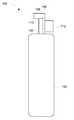
- FIG. 1is a side view of a fire detector according to one embodiment.
- FIG. 2illustrates an exemplary cross-sectional top view of an automatic activation apparatus according to one embodiment.
- FIG. 3is a block diagram of an automatic activation apparatus according to one embodiment.
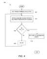
- FIG. 4is a flow diagram of a fire detection method according to one embodiment.
- FIG. 5is a flow diagram of a fire detection method according to one embodiment.
- FIG. 6illustrates a flow diagram of a fire detection method according to another embodiment.
- the inventionpertains to a fire detection device that is able to be automatically activated so as to extinguish a fire.
- the fire detectioncan be rapid and temperature-based.
- a heat collectorcan be provided to enhance thermal responsiveness.
- Activation of the fire detection devicecan be electrically induced to release an extinguishing agent at the fire. The activation can be protected such that it is durable and unaffected by vibrations.
- FIG. 1is a side view of a fire detector 100 according to one embodiment.
- the fire detector 100includes a container 102 that includes an extinguishing agent.
- the extinguishing agentcan vary depending on application and may include one or more of water, foam, or agent with nano-particles.
- Attached to the top of the container 102is a valve 104 and a nozzle 106 .
- the valve 104operates to prevent release of the extinguishing agent through the valve 104 to the nozzle 106 .
- the nozzle 106includes a nozzle opening 108 .
- the extinguishing agent from the container 102is directed under pressure through a chamber 110 within the valve 104 and on to and through the nozzle opening 108 of the nozzle 106 .
- the valve 104includes a removable valve release.
- the removable valve releaseis removed by breaking the valve release, such can be referred to as a breakable valve release.
- the valve 104prevents the release of the extinguishing agent from the container 102 .
- the removable valve releaseis broken, the extinguishing agent is released from the container 102 and flows through the chamber 110 of the valve 104 and out through the nozzle opening 108 such that it can be directed towards a fire.
- the fire extinguisher 100includes an automatic activation apparatus 112 .
- the automatic activation apparatus 112is coupled to the valve 104 .
- the automatic activation apparatus 112can, for example, monitor local temperature and induce removal (e.g., breakage) of the removable valve release (e.g., breakable valve release) when appropriate.
- the automatic activation apparatus 112can induce removal (e.g., breakage) of the removable valve release of the valve 104 .
- the automatic activation apparatus 112is able to reliably and rapidly monitor local temperature and, when appropriate, automatically activate release of the extinguishing agent from the container 102 via the nozzle 106 .
- FIG. 2illustrates an exemplary cross-sectional top view of an automatic activation apparatus 200 according to one embodiment.
- the automatic activation apparatus 200can, for example, be suitable for use as the automatic activation apparatus 112 illustrated in FIG. 1 .
- the automatic activation apparatus 200includes a housing 202 that contains the various components of the automatic activation apparatus 200 .
- the housing 202includes an opening 204 that exposes a temperature sensor 206 .
- the temperature sensor 206can vary with application and implementation.
- the temperature sensorcan be a Resistance Temperature Detectors (RTD), such as thin film RTD element.
- RTDis a sensor that measures temperature by correlating the resistance of the RTD element with temperature.
- a heat collector 208can be thermally coupled to the temperature sensor 206 .
- the heat collector 208can be formed of any of a number of different materials that offer efficient thermal conductivity.
- the heat collector 208can be made of (or at least coated with) metal, such as platinum, aluminum, gold, silver or copper.
- the heat collector 208can be formed as a sheet (e.g., plate) of metal.
- the heat collector 208can be formed as a metal coating on a substrate material (which can be a metal or non-metal material). The thickness of the heat collector 208 is generally thin for thermal responsiveness, but its thickness can vary depending on implementation.
- the thickness of the heat collectorcan vary in the range of about 0.1-0.5 millimeters.
- the heat collector 208serves to collect local heat (thermal radiation) so that the responsiveness of the temperature sensor 206 is enhanced. In other words, the heat collector 208 allows the automatic activation apparatus 202 to rapidly sense temperature conditions associated with a fire.
- the housing 202includes a substrate 210 .
- the substrate 210can pertain to a printed circuit board 210 .
- the printed circuit board 210can support one or more integrated circuits, electronic components, wire traces or wires.
- the substrate 210can support a controller 212 (e.g., microcontroller) and a voltage regulator 214 .
- the controller 212 and the voltage regulator 214are electrical circuits, and can be implemented as integrated circuits.
- the housing 202can include an opening 216 to support an activation element 218 .
- the activation element 218is a solenoid-activated device.
- the activation element 218is a miniature explosive element.
- the miniature explosive elementcan, for example, be referred to as a squib.
- the activation element 218can include a protruding member 220 .
- the activation element 218can be electrically activated and, once activated, the protruding member 220 can be rapidly forced outward.
- the protruding member 220when forced outward upon activation, can operate to remove (e.g., break) the removable release valve and thereby activate the fire extinguisher 100 so that the extinguishing agent within the container 102 is propelled outward from the nozzle opening 108 of the nozzle 106 .
- a removable valve releasee.g., breakable valve release
- the electrical components of the automatic activation apparatus 200can be powered from an externally supplied power.
- a power cord 222can provide the external power to the voltage regulator 214 which can in turn provide power to any of the electrical components, including the controller 212 and the activation element 218 .
- the external powercan be 12 Volts (V) or 24 V and the voltage regulator 214 can convert the voltage to 5 V or 3 V for use by the electrical components within the housing 202 .
- FIG. 3is a block diagram of an automatic activation apparatus 300 according to one embodiment.
- the automatic activation apparatus 300is, for example, suitable for use as the automatic activation apparatus 112 illustrated in FIG. 1 or the automatic activation apparatus 200 illustrated in FIG. 2 .
- the automatic activation apparatus 300includes a microcontroller 302 that controls the operation of the automatic activation apparatus 300 .
- the automatic activation apparatus 300also includes a voltage regulator 304 the voltage regulator 304 receives an input voltage Vcc and produces an output voltage Vdd.
- the output voltage Vddis applied to the microcontroller 302 .
- the microcontroller 302is coupled to a sensor 306 , such as a temperature sensor, and one or more resistors, such as resistors 308 , 310 and 311 .
- the microcontroller 302operates to supply a voltage Vout to the sensor 306 by way of the resistor R 1 308 . After the voltage Vout is output, the microcontroller 302 can read a sensor voltage (Vs) and an applied voltage (Va).
- the sensor voltageis the voltage across the sensor 306 by way of the resistor R 2 311 (though resistor R 2 provides has little on no voltage drop since there is little or no current).
- the applied voltageis the voltage across applied to the resistor R 1 308 by way of the resistor R 2 310 (though resistor R 2 provides has little on no voltage drop since there is little or no current).
- the applied voltageis representative of the value of the voltage Vout being used to power the sensor 306 by way of the resistors 308 and 310 . Namely, the applied voltage is the voltage applied to the resistor R 1 308 .
- the applied voltage (Va)can possibly vary with load to the voltage Vout; hence, by reading the applied voltage, the loading and thus the potentially varying voltage Vout can be monitored for more accurate temperature monitoring. However, it should be noted that in some embodiment there is not need to monitor the applied voltage (Va) since it is not substantially impacted by loading.
- the microcontroller 302can determine whether the temperature identified by the sensor 306 is indicative of a fire in the vicinity of the voltage activation apparatus 300 .
- the microcontrollercan determine the resistance of the temperature sensor 306 by use of the sensor voltage (Vs) and the applied voltage (Va).
- the resistance of the temperature sensor 306can be computed as (R 1 ⁇ Vs)/(Va ⁇ Vs).
- the microcontroller 302can determine whether the resistance of the temperature sensor 306 correlates to a temperature greater than a predetermined trip point (or threshold value).
- a control signalcan be supplied to a Field-Effect Transistor (FET) 310 which in turn supplies a modified control signal to an actuator 312 .
- FETField-Effect Transistor
- the FET 310can pertain to a current limited field-effect transistor that serves to condition the control signal for not only protection of the microcontroller 302 but also to better drive (source or sink current to) the actuator 312 .
- the modified control signalcan operate to induce the actuator 312 to cause release of an extinguishing agent.
- the actuator 312in one embodiment, can utilize a miniature explosive element that upon activation causes the release of the extinguishing agent.
- the actuator 312can use a solenoid that upon activation can induce release of the extinguishing agent.
- the actuator 312represents any mechanism that is able to cause release of the extinguishing agent in an automated fashion under the control of an electrical signal.
- the output voltage Vddcan also be supplied to the actuator 312 .
- an automatic activation apparatuscan, in general, include one or more temperature sensors.
- a controller or control circuitry of an automatic activation apparatuscan operate to sense temperature using the one or more temperature sensors.
- the controller or control circuitrycan also operate to activate one or more actuators which can cause release of extinguishing agent from one or more containers.
- a given temperature sensorcan be associated with a particular container or nozzle, such that sensing of a fire from a particular sensor can cause release of extinguishing agent from an appropriate container (or nozzle).
- the controller or control circuitrycan be sequentially activated and sensed data from the plurality of sensors, or all the sensors could always be activated and then sequentially sensed.
- one or more automatic activation apparatusescan be utilized.
- the automatic activation apparatus 112is coupled to the fire extinguisher 100 proximate to the valve 104 thereof. While this arrangement does facilitate use of the protruding member 220 of the activation element 218 to engage a removable (or breakable) portion within the valve 104 shown in FIG. 1 .
- one or more automatic activation apparatusescan be positioned differently with respect to a fire extinguisher or can be remotely located from the fire extinguisher.
- one or more wires and or a wireless communication channelcan be utilized to provide one or more control signals to an activation element which is positioned proximate to the valve 104 of the fire extinguisher 100 .
- these remotely located automatic activation apparatusescan each individually or in combination be used to detect the fire and cause an activation element of one or more fire extinguishers to cause release of an extinguishing agent.
- FIG. 4is a flow diagram of a fire detection method 400 according to one embodiment.
- the fire detection method 400can, for example, be performed by the automatic activation apparatus 112 illustrated in FIG. 1 , the automatic activation apparatus 200 illustrated in FIG. 2 , or the automatic activation apparatus 300 illustrated in FIG. 3 .
- the fire detection method 400can set 402 a predetermined value (PV) that is to be utilized to detect a fire.
- PVpredetermined value
- SCsensor characteristic
- the sensor characteristicis an electrical characteristic associated with a temperature sensor.
- the sensor characteristiccan represent current, voltage or resistance of the temperature sensor.
- the sensor characteristicis dependent upon temperature so that temperature can be monitored. The sensor characteristic is thus utilized to determine a temperature as monitored or measured by the temperature sensor.
- a decision 406can determine whether the sensor characteristic (SC) is greater than the predetermined value (PV).
- the fire detection method 400is currently not detecting the presence of fire.
- the fire detection method 400can repeat the blocks 404 and 406 until the decision 406 determines that the sensor characteristic is greater than the predetermined value.
- the delay 408can vary depending upon implementation. As an example, the delay 408 can be on the order of milliseconds or seconds.
- the fire detection method 400operates to release 410 an extinguishing agent.
- the release 410 of the extinguishing agentcan serve to suppress or extinguish a fire that has been detected by the fire detection method 400 .
- the fire detection method 400can end.
- the fire detection method 400could reset and continue to sense and extinguish one or more fires.
- FIG. 5is a flow diagram of a fire detection method 500 according to one embodiment.
- the fire detection method 500can, for example, be performed by the automatic activation apparatus 112 illustrated in FIG. 1 , the automatic activation apparatus 200 illustrated in FIG. 2 , or the automatic activation apparatus 300 illustrated in FIG. 3 .
- the fire detection method 500can be used to detect and suppress the fire.
- the fire detection method 500can set 502 a temperature trip point (TTP).
- an applied voltagecan be read 504
- a sensor voltagecan be read 506 .
- the applied voltageis the voltage associated with a voltage being applied to sensor circuitry including a temperature sensor, and the sensor voltage is the voltage at the temperature sensor.
- a sensor resistancecan be determined 508 based on the sensor voltage and the applied voltage.
- a decision 510can determine whether the sensor resistance (SR) is greater than the temperature trip point (TTP). When the decision 510 determines that the sensor resistance is not greater than the temperature trip point, the fire detection method 500 is currently not detecting the presence of a fire. Hence, in this case, after an optional delay 512 , the fire detection method 500 can return to repeat the block 504 and subsequent blocks so that the temperature sensor can be repeatedly monitored so that the presence of a fire can be rapidly detected.
- the delay 512can vary depending upon implementation. For example, the delay 512 can be on the order of milliseconds or seconds.
- the fire detection method 500when the decision 510 determines that the sensor resistance is greater than the temperature trip point, the fire detection method 500 has detected a fire. Consequently, in this case, the fire detection method 500 can release 514 an extinguishing agent. The extinguishing agent can then suppress or extinguish the fire that has been detected. Following the release 514 of the extinguishing agent, the fire detection method 500 can end. However, in other embodiments, if there is additional extinguishing agent available, the fire detection method 500 could reset and continue to sense and extinguish one or more fires.
- FIG. 6illustrates a flow diagram of a fire detection method 600 according to another embodiment.
- the fire detection method 600can, for example, be performed by the automatic activation apparatus 112 illustrated in FIG. 1 , the automatic activation apparatus 200 illustrated in FIG. 2 , or the automatic activation apparatus 300 illustrated in FIG. 3 .
- the fire detection method 600can set 602 a temperature trip point (TIP). Next, an applied voltage can be read 604 , and a sensor voltage can be read 606 . Then, a sensor resistance (SR) can be determined 608 based on the sensor voltage and the applied voltage. The sensor resistance can then be accumulated 610 . The accumulation of the sensor resistance can be performed a predetermined number (X) times. A decision 612 can determine whether the sensor voltage and the sensor resistance determination (and its accumulation) should be repeated. For example, the decision 612 can cause the blocks 604 through 610 to be performed a total of X times. Between each repetition, a delay 614 can be optionally provided. The delay can serve to reduce power consumption, but the delay is typically kept rather short (e.g., less than 10 millisecond (ms)) so that responsiveness does not substantially suffer.
- msmillisecond
- an average sensor resistancecan be computed by dividing the accumulated sensor resistance by X.
- a decision 618can then determine whether the average sensor resistance (SRave) is greater than the temperature trip point (TTP). When the decision 618 determines that the average sensor resistance is not greater than the temperature trip point, the fire detection method 600 can return to repeat the block 604 and subsequent blocks so that fire detection can continue.
- a delay 620can optionally be imposed before repeating the block 604 and subsequent blocks. Although the delay 620 can serve to reduce power consumption, the delays maintained relatively short (e.g., less than 10 seconds) so that the responsiveness of the fire detection capability remains rapid.
- the fire detection method 600can release 622 an extinguishing agent.
- the extinguishing agent upon being releasedcan serve to suppress or extinguish the fire that has been detected.
- the fire detection method 600can end.
- the fire detection method 600could reset and continue to sense and extinguish one or more fires.
Landscapes
- Health & Medical Sciences (AREA)
- Public Health (AREA)
- Business, Economics & Management (AREA)
- Emergency Management (AREA)
- Fire-Detection Mechanisms (AREA)
- Fire Alarms (AREA)
Abstract
Description
Claims (16)
Priority Applications (6)
| Application Number | Priority Date | Filing Date | Title |
|---|---|---|---|
| US13/405,139US9162095B2 (en) | 2011-03-09 | 2012-02-24 | Temperature-based fire detection |
| US14/878,864US10086224B2 (en) | 2011-03-09 | 2015-10-08 | Temperature-based fire detection |
| US16/138,858US10376725B2 (en) | 2011-03-09 | 2018-09-21 | Temperature-based fire detection |
| US16/536,296US10864398B2 (en) | 2011-03-09 | 2019-08-08 | Temperature-based fire protection |
| US17/122,891US11504562B2 (en) | 2011-03-09 | 2020-12-15 | Automated fire detection with portable fire extinguisher |
| US17/982,460US11904195B2 (en) | 2011-03-09 | 2022-11-07 | Self-contained fire extinguisher with automated fire detection |
Applications Claiming Priority (2)
| Application Number | Priority Date | Filing Date | Title |
|---|---|---|---|
| US201161451062P | 2011-03-09 | 2011-03-09 | |
| US13/405,139US9162095B2 (en) | 2011-03-09 | 2012-02-24 | Temperature-based fire detection |
Related Child Applications (1)
| Application Number | Title | Priority Date | Filing Date |
|---|---|---|---|
| US14/878,864ContinuationUS10086224B2 (en) | 2011-03-09 | 2015-10-08 | Temperature-based fire detection |
Publications (2)
| Publication Number | Publication Date |
|---|---|
| US20120227989A1 US20120227989A1 (en) | 2012-09-13 |
| US9162095B2true US9162095B2 (en) | 2015-10-20 |
Family
ID=46794483
Family Applications (6)
| Application Number | Title | Priority Date | Filing Date |
|---|---|---|---|
| US13/405,139Active - Reinstated2033-09-14US9162095B2 (en) | 2011-03-09 | 2012-02-24 | Temperature-based fire detection |
| US14/878,864Expired - Fee RelatedUS10086224B2 (en) | 2011-03-09 | 2015-10-08 | Temperature-based fire detection |
| US16/138,858Expired - Fee RelatedUS10376725B2 (en) | 2011-03-09 | 2018-09-21 | Temperature-based fire detection |
| US16/536,296Expired - Fee RelatedUS10864398B2 (en) | 2011-03-09 | 2019-08-08 | Temperature-based fire protection |
| US17/122,891ActiveUS11504562B2 (en) | 2011-03-09 | 2020-12-15 | Automated fire detection with portable fire extinguisher |
| US17/982,460ActiveUS11904195B2 (en) | 2011-03-09 | 2022-11-07 | Self-contained fire extinguisher with automated fire detection |
Family Applications After (5)
| Application Number | Title | Priority Date | Filing Date |
|---|---|---|---|
| US14/878,864Expired - Fee RelatedUS10086224B2 (en) | 2011-03-09 | 2015-10-08 | Temperature-based fire detection |
| US16/138,858Expired - Fee RelatedUS10376725B2 (en) | 2011-03-09 | 2018-09-21 | Temperature-based fire detection |
| US16/536,296Expired - Fee RelatedUS10864398B2 (en) | 2011-03-09 | 2019-08-08 | Temperature-based fire protection |
| US17/122,891ActiveUS11504562B2 (en) | 2011-03-09 | 2020-12-15 | Automated fire detection with portable fire extinguisher |
| US17/982,460ActiveUS11904195B2 (en) | 2011-03-09 | 2022-11-07 | Self-contained fire extinguisher with automated fire detection |
Country Status (1)
| Country | Link |
|---|---|
| US (6) | US9162095B2 (en) |
Cited By (1)
| Publication number | Priority date | Publication date | Assignee | Title |
|---|---|---|---|---|
| US10086224B2 (en) | 2011-03-09 | 2018-10-02 | Alan E. Thomas | Temperature-based fire detection |
Families Citing this family (13)
| Publication number | Priority date | Publication date | Assignee | Title |
|---|---|---|---|---|
| DE102013007569B4 (en) | 2013-05-02 | 2022-11-17 | Antonios Kokas | Automatic trigger for a mobile fire extinguisher and mobile fire extinguisher equipped therewith |
| US20190099630A1 (en) | 2014-03-19 | 2019-04-04 | Firebird Sprinklker Company LLC | Multi-head array fire sprinkler system for storage applications |
| US10493308B2 (en) | 2014-03-19 | 2019-12-03 | Firebird Sprinkler Company Llc | Multi-head array fire sprinkler system with heat shields |
| US20220161081A1 (en) | 2014-03-19 | 2022-05-26 | Firebird Sprinkler Company Llc | Combustible attic fire protection scheme |
| US20150265865A1 (en) | 2014-03-19 | 2015-09-24 | Jeffrey J. Pigeon | Fire sprinkler system |
| US20170335983A1 (en)* | 2016-05-20 | 2017-11-23 | S.P.A. Automotive Limited | Valve assembly |
| US20190015688A1 (en)* | 2016-10-05 | 2019-01-17 | WilliamsRDM Inc. | Self Contained Stovetop Fire Suppressor with Sensor Triggered Shuttle Activation and Method |
| US10479739B2 (en)* | 2017-05-04 | 2019-11-19 | Honeywell International Inc. | Integrated system for oxygen recovery for deep space mission |
| CA3090514A1 (en) | 2018-02-14 | 2019-08-22 | Victaulic Company | Fire protection system for sloped combustible concealed spaces |
| CN108714284B (en)* | 2018-03-27 | 2020-09-25 | 英业达科技有限公司 | Intelligent starting system and method for fire fighting equipment |
| AU2020287113A1 (en) | 2019-06-07 | 2021-12-23 | Victaulic Company | Fire protection system for sloped combustible concealed spaces having hips |
| CN110354433A (en)* | 2019-07-25 | 2019-10-22 | 吴清勋 | Thermal sensation temperature control type automatic fire extinguisher |
| CN120204671B (en)* | 2025-05-28 | 2025-08-08 | 国网甘肃省电力公司天水供电公司 | Automatic fire extinguishing control method and device based on power data monitoring |
Citations (53)
| Publication number | Priority date | Publication date | Assignee | Title |
|---|---|---|---|---|
| US3493953A (en) | 1965-08-14 | 1970-02-03 | Thrings Advanced Dev Ltd | Fire alarm with infra-red scanner |
| US3665440A (en) | 1969-08-19 | 1972-05-23 | Teeg Research Inc | Fire detector utilizing ultraviolet and infrared sensors |
| US3689773A (en) | 1971-02-01 | 1972-09-05 | Bailey Miters & Controls Ltd | Flame monitor system and method using multiple radiation sensors |
| US3739365A (en) | 1969-12-03 | 1973-06-12 | Cerberus Ag | Apparatus for detection of a fire or of flames |
| US3824392A (en) | 1972-04-24 | 1974-07-16 | Pak Const Ab | Detector to indicate burning or glowing particles |
| US3993138A (en) | 1975-04-24 | 1976-11-23 | The United States Of America As Represented By The Secretary Of The Interior | Fire prevention system |
| US4003048A (en) | 1976-02-23 | 1977-01-11 | George Weise | Remote alarm system for detection of fire extinguisher removal |
| US4299289A (en) | 1978-01-11 | 1981-11-10 | Kiyoshi Kato | Fire extinguisher having a heat fusible member under compression |
| US4455487A (en) | 1981-10-30 | 1984-06-19 | Armtec Industries, Inc. | Fire detection system with IR and UV ratio detector |
| US4553031A (en) | 1983-09-06 | 1985-11-12 | Firetek Corporation | Optical fire or explosion detection system and method |
| US4556873A (en) | 1983-04-30 | 1985-12-03 | Matsushita Electric Works, Ltd. | Fire alarm system |
| US4648462A (en) | 1985-04-23 | 1987-03-10 | Tekken Construction Co., Ltd. | Automatic fire extinguisher with infrared ray responsive type fire detector |
| US4671362A (en) | 1985-04-23 | 1987-06-09 | Tekken Construction Co., Ltd. | Automatic fire extinguisher with infrared ray responsive type fire detector |
| US4691783A (en) | 1986-03-06 | 1987-09-08 | Spectronix Ltd. | Automatic modular fire extinguisher system for computer rooms |
| US4755687A (en) | 1984-12-27 | 1988-07-05 | Hochiki Corp. | System and method for detecting flames |
| US4800285A (en) | 1986-06-30 | 1989-01-24 | Hochiki Kabushiki Kaisha | Flame detecting arrangement for detecting a flame through horizontal and vertical scanning of a supervisory region by using a photodetector |
| US4830116A (en)* | 1987-07-06 | 1989-05-16 | Walden James W | Fire extinguishing system |
| US4861998A (en) | 1986-01-10 | 1989-08-29 | Thomson-Csf | Rapid fire-detection device for armored vehicles |
| US4887674A (en)* | 1988-03-22 | 1989-12-19 | Galosky David G | Cartridge operated fire extinguisher |
| US4893680A (en)* | 1988-10-17 | 1990-01-16 | The United States Of America As Represented By The Secretary Of The Army | Fire suppression activator |
| US4905765A (en) | 1988-08-22 | 1990-03-06 | Hein George P | Smoke detector/remote controlled shape-memory alloy fire extinguisher discharge apparatus |
| US4909329A (en) | 1986-08-27 | 1990-03-20 | Kabushiki Kaisha Kockiki Corp. | Fire supervising system and extinguishing target determining system |
| US4984637A (en)* | 1989-06-23 | 1991-01-15 | Finnigan Wilfred J | Electronic fire protection system |
| US5022014A (en) | 1988-06-15 | 1991-06-04 | Schlumberger Industries Limited | Ultrasonic temperature sensors, and ultrasonic waveguide connectors for use therewith |
| US5038866A (en)* | 1986-11-21 | 1991-08-13 | Santa Barbara Research Center | Powder discharge apparatus |
| US5107128A (en) | 1989-05-05 | 1992-04-21 | Saskatchewan Power Corporation | Method and apparatus for detecting flame with adjustable optical coupling |
| US5207276A (en)* | 1991-04-25 | 1993-05-04 | Pem All Fire Extinguisher Corp. | Wire-sensored fire extinguisher with fault-monitoring control system |
| US5463375A (en) | 1990-06-19 | 1995-10-31 | Dylec Ltd. | Status-reporting device for reporting a predetermined temperature state, temperature sensor suitable for such a status-reporting device, and process for the production of such a temperature sensor |
| US5518075A (en) | 1994-01-21 | 1996-05-21 | Williams; Robert A. | Fire extinguisher |
| US5548276A (en) | 1993-11-30 | 1996-08-20 | Alan E. Thomas | Localized automatic fire extinguishing apparatus |
| US5697450A (en) | 1993-04-28 | 1997-12-16 | Twenty First Century International Fire Equipement And Services Corp. | Fire extinguishing systems and methods |
| US5775430A (en) | 1996-01-23 | 1998-07-07 | Mija Industries, Inc. | Electroluminescent signalling fire extinguisher |
| US5808541A (en) | 1995-04-04 | 1998-09-15 | Golden; Patrick E. | Hazard detection, warning, and response system |
| US5826664A (en) | 1996-12-20 | 1998-10-27 | Mcdonnell Douglas Corporation | Active fire and explosion suppression system employing a recloseable valve |
| US5871057A (en) | 1993-04-28 | 1999-02-16 | Twenty First Century International Fire Equipment And Service Corp. | Fire extinguishing systems and methods |
| US5883568A (en)* | 1992-07-01 | 1999-03-16 | Computer Fire Products Solutions, Inc. | Alarm system for detecting excess temperature in electrical wiring |
| US5890544A (en) | 1998-01-28 | 1999-04-06 | Love; Robert | Self-contained remote automated fire suppression |
| US5960888A (en) | 1998-04-23 | 1999-10-05 | Moore, Sr.; Garry L. | Engine fire suppression system |
| US6364026B1 (en) | 1998-04-01 | 2002-04-02 | Irving Doshay | Robotic fire protection system |
| US6491110B2 (en)* | 2000-05-02 | 2002-12-10 | Jong Jin Gil | Thermal ampoule for sprinkler |
| US6515283B1 (en) | 1996-03-01 | 2003-02-04 | Fire Sentry Corporation | Fire detector with modulation index measurement |
| US6518574B1 (en) | 1996-03-01 | 2003-02-11 | Fire Sentry Corporation | Fire detector with multiple sensors |
| US6632134B2 (en) | 2002-01-03 | 2003-10-14 | Deponio Wallace A. | Building fire extinguisher system |
| US6768424B1 (en) | 1999-01-21 | 2004-07-27 | Gary J. Morris | Environmental condition detector with remote fire extinguisher locator system |
| US6866102B2 (en) | 2003-04-28 | 2005-03-15 | Lenuel Boyce | Electrical fire extinguishing system |
| US6896066B2 (en)* | 2000-02-21 | 2005-05-24 | Jong Jin Gil | Sprinkler apparatus and method for controlling the same |
| US6981555B2 (en) | 2002-02-11 | 2006-01-03 | Smith Bradley W | Modular fire detection and extinguishing system |
| USRE39081E1 (en) | 1993-11-30 | 2006-05-02 | Alan E. Thomas | Localized automatic fire extinguishing apparatus |
| US7154388B2 (en) | 2003-11-13 | 2006-12-26 | The Boeing Company | Vehicle compartment smoke and fire indication system and method for use |
| US7336168B2 (en) | 2005-06-06 | 2008-02-26 | Lawrence Kates | System and method for variable threshold sensor |
| US7505604B2 (en) | 2002-05-20 | 2009-03-17 | Simmonds Precision Prodcuts, Inc. | Method for detection and recognition of fog presence within an aircraft compartment using video images |
| US7740081B2 (en) | 2007-05-25 | 2010-06-22 | Tsm Corporation | Hazard detection and suppression apparatus |
| US7817048B2 (en) | 2008-05-30 | 2010-10-19 | Guardian Patent, Llc | Fire extinguishing systems and methods |
Family Cites Families (10)
| Publication number | Priority date | Publication date | Assignee | Title |
|---|---|---|---|---|
| US1510649A (en)* | 1919-07-24 | 1924-10-07 | Harrison H Boyce | Fire extinguisher |
| US3517746A (en)* | 1968-04-24 | 1970-06-30 | Gen Fire Extinguisher Corp | Dry chemical fire extinguishing system |
| US3719231A (en)* | 1971-05-14 | 1973-03-06 | K Haggard | Attachment for automatic override of manually operated compressed gas fire extinguishers and alarms |
| US3853180A (en)* | 1973-10-12 | 1974-12-10 | Intercontinental Equip Corp | Operating heads for fire extinguishers |
| US4098343A (en)* | 1977-01-19 | 1978-07-04 | Carroll John L | Automatically and manually controlled fire extinguisher |
| US6029751A (en)* | 1997-02-07 | 2000-02-29 | Ford; Wallace Wayne | Automatic fire suppression apparatus and method |
| US20080271902A1 (en)* | 2007-05-03 | 2008-11-06 | Cjs Concepts, Llc | Fire prevention and extinguishing system and method of using same |
| US20090050339A1 (en)* | 2007-08-21 | 2009-02-26 | Calabrese Charles A | System and method for extinguishing a fire |
| US20090321093A1 (en)* | 2008-06-29 | 2009-12-31 | Shlomo Lalouz | Home kitchen fire suppression system |
| US9162095B2 (en) | 2011-03-09 | 2015-10-20 | Alan E. Thomas | Temperature-based fire detection |
- 2012
- 2012-02-24USUS13/405,139patent/US9162095B2/enactiveActive - Reinstated
- 2015
- 2015-10-08USUS14/878,864patent/US10086224B2/ennot_activeExpired - Fee Related
- 2018
- 2018-09-21USUS16/138,858patent/US10376725B2/ennot_activeExpired - Fee Related
- 2019
- 2019-08-08USUS16/536,296patent/US10864398B2/ennot_activeExpired - Fee Related
- 2020
- 2020-12-15USUS17/122,891patent/US11504562B2/enactiveActive
- 2022
- 2022-11-07USUS17/982,460patent/US11904195B2/enactiveActive
Patent Citations (59)
| Publication number | Priority date | Publication date | Assignee | Title |
|---|---|---|---|---|
| US3493953A (en) | 1965-08-14 | 1970-02-03 | Thrings Advanced Dev Ltd | Fire alarm with infra-red scanner |
| US3665440A (en) | 1969-08-19 | 1972-05-23 | Teeg Research Inc | Fire detector utilizing ultraviolet and infrared sensors |
| US3739365A (en) | 1969-12-03 | 1973-06-12 | Cerberus Ag | Apparatus for detection of a fire or of flames |
| US3689773A (en) | 1971-02-01 | 1972-09-05 | Bailey Miters & Controls Ltd | Flame monitor system and method using multiple radiation sensors |
| US3824392A (en) | 1972-04-24 | 1974-07-16 | Pak Const Ab | Detector to indicate burning or glowing particles |
| US3993138A (en) | 1975-04-24 | 1976-11-23 | The United States Of America As Represented By The Secretary Of The Interior | Fire prevention system |
| US4003048A (en) | 1976-02-23 | 1977-01-11 | George Weise | Remote alarm system for detection of fire extinguisher removal |
| US4299289A (en) | 1978-01-11 | 1981-11-10 | Kiyoshi Kato | Fire extinguisher having a heat fusible member under compression |
| US4455487A (en) | 1981-10-30 | 1984-06-19 | Armtec Industries, Inc. | Fire detection system with IR and UV ratio detector |
| US4556873A (en) | 1983-04-30 | 1985-12-03 | Matsushita Electric Works, Ltd. | Fire alarm system |
| US4553031A (en) | 1983-09-06 | 1985-11-12 | Firetek Corporation | Optical fire or explosion detection system and method |
| US4755687A (en) | 1984-12-27 | 1988-07-05 | Hochiki Corp. | System and method for detecting flames |
| US4648462A (en) | 1985-04-23 | 1987-03-10 | Tekken Construction Co., Ltd. | Automatic fire extinguisher with infrared ray responsive type fire detector |
| US4671362A (en) | 1985-04-23 | 1987-06-09 | Tekken Construction Co., Ltd. | Automatic fire extinguisher with infrared ray responsive type fire detector |
| US4861998A (en) | 1986-01-10 | 1989-08-29 | Thomson-Csf | Rapid fire-detection device for armored vehicles |
| US4691783A (en) | 1986-03-06 | 1987-09-08 | Spectronix Ltd. | Automatic modular fire extinguisher system for computer rooms |
| US4800285A (en) | 1986-06-30 | 1989-01-24 | Hochiki Kabushiki Kaisha | Flame detecting arrangement for detecting a flame through horizontal and vertical scanning of a supervisory region by using a photodetector |
| US4909329A (en) | 1986-08-27 | 1990-03-20 | Kabushiki Kaisha Kockiki Corp. | Fire supervising system and extinguishing target determining system |
| US5038866A (en)* | 1986-11-21 | 1991-08-13 | Santa Barbara Research Center | Powder discharge apparatus |
| US4830116A (en)* | 1987-07-06 | 1989-05-16 | Walden James W | Fire extinguishing system |
| US4887674A (en)* | 1988-03-22 | 1989-12-19 | Galosky David G | Cartridge operated fire extinguisher |
| US5022014A (en) | 1988-06-15 | 1991-06-04 | Schlumberger Industries Limited | Ultrasonic temperature sensors, and ultrasonic waveguide connectors for use therewith |
| US4905765A (en) | 1988-08-22 | 1990-03-06 | Hein George P | Smoke detector/remote controlled shape-memory alloy fire extinguisher discharge apparatus |
| US4893680A (en)* | 1988-10-17 | 1990-01-16 | The United States Of America As Represented By The Secretary Of The Army | Fire suppression activator |
| US5107128A (en) | 1989-05-05 | 1992-04-21 | Saskatchewan Power Corporation | Method and apparatus for detecting flame with adjustable optical coupling |
| US4984637A (en)* | 1989-06-23 | 1991-01-15 | Finnigan Wilfred J | Electronic fire protection system |
| US5463375A (en) | 1990-06-19 | 1995-10-31 | Dylec Ltd. | Status-reporting device for reporting a predetermined temperature state, temperature sensor suitable for such a status-reporting device, and process for the production of such a temperature sensor |
| US5207276A (en)* | 1991-04-25 | 1993-05-04 | Pem All Fire Extinguisher Corp. | Wire-sensored fire extinguisher with fault-monitoring control system |
| US5883568A (en)* | 1992-07-01 | 1999-03-16 | Computer Fire Products Solutions, Inc. | Alarm system for detecting excess temperature in electrical wiring |
| US6044913A (en) | 1993-04-28 | 2000-04-04 | Twenty-First Century International Fire Equipment And Services Corporation | Fire extinguishing systems and methods |
| US5871057A (en) | 1993-04-28 | 1999-02-16 | Twenty First Century International Fire Equipment And Service Corp. | Fire extinguishing systems and methods |
| US5697450A (en) | 1993-04-28 | 1997-12-16 | Twenty First Century International Fire Equipement And Services Corp. | Fire extinguishing systems and methods |
| US5548276A (en) | 1993-11-30 | 1996-08-20 | Alan E. Thomas | Localized automatic fire extinguishing apparatus |
| USRE39081E1 (en) | 1993-11-30 | 2006-05-02 | Alan E. Thomas | Localized automatic fire extinguishing apparatus |
| USRE37493E1 (en) | 1993-11-30 | 2002-01-01 | Alan E. Thomas | Localized automatic fire extinguishing apparatus |
| US5518075A (en) | 1994-01-21 | 1996-05-21 | Williams; Robert A. | Fire extinguisher |
| US5808541A (en) | 1995-04-04 | 1998-09-15 | Golden; Patrick E. | Hazard detection, warning, and response system |
| US6104301A (en) | 1995-04-04 | 2000-08-15 | Golden; Patrick E. | Hazard detection, warning, and response system |
| US6302218B1 (en) | 1996-01-23 | 2001-10-16 | Mija Industries, Inc. | Signalling portable pressurized equipment assembly |
| US6311779B2 (en) | 1996-01-23 | 2001-11-06 | Mija Industries, Inc. | Signalling fire extinguisher assembly |
| US5775430A (en) | 1996-01-23 | 1998-07-07 | Mija Industries, Inc. | Electroluminescent signalling fire extinguisher |
| US5848651A (en) | 1996-01-23 | 1998-12-15 | Mija Industries, Inc. | Signalling fire extinguisher assembly |
| US6515283B1 (en) | 1996-03-01 | 2003-02-04 | Fire Sentry Corporation | Fire detector with modulation index measurement |
| US6518574B1 (en) | 1996-03-01 | 2003-02-11 | Fire Sentry Corporation | Fire detector with multiple sensors |
| US5826664A (en) | 1996-12-20 | 1998-10-27 | Mcdonnell Douglas Corporation | Active fire and explosion suppression system employing a recloseable valve |
| US5890544A (en) | 1998-01-28 | 1999-04-06 | Love; Robert | Self-contained remote automated fire suppression |
| US6364026B1 (en) | 1998-04-01 | 2002-04-02 | Irving Doshay | Robotic fire protection system |
| US5960888A (en) | 1998-04-23 | 1999-10-05 | Moore, Sr.; Garry L. | Engine fire suppression system |
| US6768424B1 (en) | 1999-01-21 | 2004-07-27 | Gary J. Morris | Environmental condition detector with remote fire extinguisher locator system |
| US6896066B2 (en)* | 2000-02-21 | 2005-05-24 | Jong Jin Gil | Sprinkler apparatus and method for controlling the same |
| US6491110B2 (en)* | 2000-05-02 | 2002-12-10 | Jong Jin Gil | Thermal ampoule for sprinkler |
| US6632134B2 (en) | 2002-01-03 | 2003-10-14 | Deponio Wallace A. | Building fire extinguisher system |
| US6981555B2 (en) | 2002-02-11 | 2006-01-03 | Smith Bradley W | Modular fire detection and extinguishing system |
| US7505604B2 (en) | 2002-05-20 | 2009-03-17 | Simmonds Precision Prodcuts, Inc. | Method for detection and recognition of fog presence within an aircraft compartment using video images |
| US6866102B2 (en) | 2003-04-28 | 2005-03-15 | Lenuel Boyce | Electrical fire extinguishing system |
| US7154388B2 (en) | 2003-11-13 | 2006-12-26 | The Boeing Company | Vehicle compartment smoke and fire indication system and method for use |
| US7336168B2 (en) | 2005-06-06 | 2008-02-26 | Lawrence Kates | System and method for variable threshold sensor |
| US7740081B2 (en) | 2007-05-25 | 2010-06-22 | Tsm Corporation | Hazard detection and suppression apparatus |
| US7817048B2 (en) | 2008-05-30 | 2010-10-19 | Guardian Patent, Llc | Fire extinguishing systems and methods |
Non-Patent Citations (3)
| Title |
|---|
| Data Sheet, Metron Protractor DR 2005 C1, downloaded Mar. 18, 2012, 1 page. |
| omega.com, Home Webpage, Your One-Stop Source for Process Measurement and Control!, http://www.omega.com, downloaded Mar. 18, 2012, 1 page. |
| ThinFilm RTD Elements, "F" Series for OED Applications, downloaded Mar. 18, 2012, 1 page. |
Cited By (6)
| Publication number | Priority date | Publication date | Assignee | Title |
|---|---|---|---|---|
| US10086224B2 (en) | 2011-03-09 | 2018-10-02 | Alan E. Thomas | Temperature-based fire detection |
| US10376725B2 (en) | 2011-03-09 | 2019-08-13 | C. Douglass Thomas | Temperature-based fire detection |
| US20190358478A1 (en)* | 2011-03-09 | 2019-11-28 | Alan E. Thomes | Temperature-Based Fire Protection |
| US10864398B2 (en)* | 2011-03-09 | 2020-12-15 | C. Douglass Thomas | Temperature-based fire protection |
| US11504562B2 (en)* | 2011-03-09 | 2022-11-22 | C. Douglass Thomas | Automated fire detection with portable fire extinguisher |
| US11904195B2 (en) | 2011-03-09 | 2024-02-20 | C. Douglass Thomas | Self-contained fire extinguisher with automated fire detection |
Also Published As
| Publication number | Publication date |
|---|---|
| US20190358478A1 (en) | 2019-11-28 |
| US20190022444A1 (en) | 2019-01-24 |
| US10376725B2 (en) | 2019-08-13 |
| US10864398B2 (en) | 2020-12-15 |
| US20120227989A1 (en) | 2012-09-13 |
| US20210101039A1 (en) | 2021-04-08 |
| US11904195B2 (en) | 2024-02-20 |
| US11504562B2 (en) | 2022-11-22 |
| US20160023031A1 (en) | 2016-01-28 |
| US10086224B2 (en) | 2018-10-02 |
| US20230065590A1 (en) | 2023-03-02 |
Similar Documents
| Publication | Publication Date | Title |
|---|---|---|
| US11904195B2 (en) | Self-contained fire extinguisher with automated fire detection | |
| US11065867B2 (en) | Detecting a drive bubble formation and collapse | |
| EP3543710B1 (en) | Power efficient heater control of air data sensor | |
| EP2870435B1 (en) | Cloud ice detector | |
| EP2132091B1 (en) | Method and device for detecting rime and/or rime conditions on a flying aircraft | |
| CA2284258C (en) | Device and method for detecting snow and ice | |
| EP1394720A2 (en) | Device suitable to detect the presence of a transponder in its vicinity | |
| KR20180062462A (en) | Liquid level indication | |
| AU2018255373B2 (en) | Smoke detector availability test | |
| SE532446C2 (en) | Fire protection system for a clothes dryer | |
| WO2008051673A2 (en) | Detecting ice particles | |
| KR101864612B1 (en) | Method and apparatus for warning a fire cooperating with automatic vantilation system | |
| RU2005102824A (en) | METHOD FOR MEASURING AND REGULATING THE CRUSH CRACK SIZE AND DEVICE FOR ITS IMPLEMENTATION | |
| CN108305430B (en) | A fire warning system | |
| JP2020071684A (en) | Temperature abnormality detection system, temperature abnormality detection method, and program | |
| US4882574A (en) | Two-resistor ice detector | |
| JP5062657B2 (en) | Abnormality detection device and abnormality detection method for sensor chip with heater | |
| EP2894464B1 (en) | Microsensor for gas flow and concentration measurements | |
| EP3478025A1 (en) | Self-regulating heater compensation | |
| US2749993A (en) | Fire extinguisher | |
| JP2009059135A (en) | Photoelectric type smoke detector | |
| Akande et al. | Research Article UAV and Its Approach in Oil and Gas Pipeline Leakage Detection | |
| FR3128566B3 (en) | Forest fire monitoring device and method | |
| JPS6361605B2 (en) | ||
| JPH09222406A (en) | Gas detection method and gas detection device |
Legal Events
| Date | Code | Title | Description |
|---|---|---|---|
| STCF | Information on status: patent grant | Free format text:PATENTED CASE | |
| FEPP | Fee payment procedure | Free format text:MAINTENANCE FEE REMINDER MAILED (ORIGINAL EVENT CODE: REM.); ENTITY STATUS OF PATENT OWNER: SMALL ENTITY | |
| LAPS | Lapse for failure to pay maintenance fees | Free format text:PATENT EXPIRED FOR FAILURE TO PAY MAINTENANCE FEES (ORIGINAL EVENT CODE: EXP.); ENTITY STATUS OF PATENT OWNER: SMALL ENTITY | |
| STCH | Information on status: patent discontinuation | Free format text:PATENT EXPIRED DUE TO NONPAYMENT OF MAINTENANCE FEES UNDER 37 CFR 1.362 | |
| FP | Lapsed due to failure to pay maintenance fee | Effective date:20191020 | |
| FEPP | Fee payment procedure | Free format text:PETITION RELATED TO MAINTENANCE FEES FILED (ORIGINAL EVENT CODE: PMFP); ENTITY STATUS OF PATENT OWNER: SMALL ENTITY Free format text:SURCHARGE, PETITION TO ACCEPT PYMT AFTER EXP, UNINTENTIONAL. (ORIGINAL EVENT CODE: M2558); ENTITY STATUS OF PATENT OWNER: SMALL ENTITY | |
| MAFP | Maintenance fee payment | Free format text:PAYMENT OF MAINTENANCE FEE, 4TH YR, SMALL ENTITY (ORIGINAL EVENT CODE: M2551); ENTITY STATUS OF PATENT OWNER: SMALL ENTITY Year of fee payment:4 | |
| FEPP | Fee payment procedure | Free format text:PETITION RELATED TO MAINTENANCE FEES DISMISSED (ORIGINAL EVENT CODE: PMFS); ENTITY STATUS OF PATENT OWNER: SMALL ENTITY | |
| FEPP | Fee payment procedure | Free format text:PETITION RELATED TO MAINTENANCE FEES FILED (ORIGINAL EVENT CODE: PMFP); ENTITY STATUS OF PATENT OWNER: SMALL ENTITY | |
| FEPP | Fee payment procedure | Free format text:PETITION RELATED TO MAINTENANCE FEES GRANTED (ORIGINAL EVENT CODE: PMFG); ENTITY STATUS OF PATENT OWNER: SMALL ENTITY | |
| STCF | Information on status: patent grant | Free format text:PATENTED CASE | |
| FEPP | Fee payment procedure | Free format text:MAINTENANCE FEE REMINDER MAILED (ORIGINAL EVENT CODE: REM.); ENTITY STATUS OF PATENT OWNER: SMALL ENTITY | |
| FEPP | Fee payment procedure | Free format text:7.5 YR SURCHARGE - LATE PMT W/IN 6 MO, SMALL ENTITY (ORIGINAL EVENT CODE: M2555); ENTITY STATUS OF PATENT OWNER: SMALL ENTITY | |
| MAFP | Maintenance fee payment | Free format text:PAYMENT OF MAINTENANCE FEE, 8TH YR, SMALL ENTITY (ORIGINAL EVENT CODE: M2552); ENTITY STATUS OF PATENT OWNER: SMALL ENTITY Year of fee payment:8 | |
| PRDP | Patent reinstated due to the acceptance of a late maintenance fee | Effective date:20230117 |