US9162017B2 - Expandable vascular pump - Google Patents
Expandable vascular pumpDownload PDFInfo
- Publication number
- US9162017B2 US9162017B2US13/590,564US201213590564AUS9162017B2US 9162017 B2US9162017 B2US 9162017B2US 201213590564 AUS201213590564 AUS 201213590564AUS 9162017 B2US9162017 B2US 9162017B2
- Authority
- US
- United States
- Prior art keywords
- cannula
- impeller
- pump
- configuration
- catheter
- Prior art date
- Legal status (The legal status is an assumption and is not a legal conclusion. Google has not performed a legal analysis and makes no representation as to the accuracy of the status listed.)
- Active
Links
Images


Classifications
- A61M1/101—
- A—HUMAN NECESSITIES
- A61—MEDICAL OR VETERINARY SCIENCE; HYGIENE
- A61M—DEVICES FOR INTRODUCING MEDIA INTO, OR ONTO, THE BODY; DEVICES FOR TRANSDUCING BODY MEDIA OR FOR TAKING MEDIA FROM THE BODY; DEVICES FOR PRODUCING OR ENDING SLEEP OR STUPOR
- A61M60/00—Blood pumps; Devices for mechanical circulatory actuation; Balloon pumps for circulatory assistance
- A61M60/40—Details relating to driving
- A61M60/403—Details relating to driving for non-positive displacement blood pumps
- A61M60/405—Details relating to driving for non-positive displacement blood pumps the force acting on the blood contacting member being hydraulic or pneumatic
- A61M1/1024—
- A61M1/1032—
- A61M1/1034—
- A61M1/125—
- A—HUMAN NECESSITIES
- A61—MEDICAL OR VETERINARY SCIENCE; HYGIENE
- A61M—DEVICES FOR INTRODUCING MEDIA INTO, OR ONTO, THE BODY; DEVICES FOR TRANSDUCING BODY MEDIA OR FOR TAKING MEDIA FROM THE BODY; DEVICES FOR PRODUCING OR ENDING SLEEP OR STUPOR
- A61M60/00—Blood pumps; Devices for mechanical circulatory actuation; Balloon pumps for circulatory assistance
- A61M60/10—Location thereof with respect to the patient's body
- A61M60/122—Implantable pumps or pumping devices, i.e. the blood being pumped inside the patient's body
- A61M60/126—Implantable pumps or pumping devices, i.e. the blood being pumped inside the patient's body implantable via, into, inside, in line, branching on, or around a blood vessel
- A61M60/13—Implantable pumps or pumping devices, i.e. the blood being pumped inside the patient's body implantable via, into, inside, in line, branching on, or around a blood vessel by means of a catheter allowing explantation, e.g. catheter pumps temporarily introduced via the vascular system
- A—HUMAN NECESSITIES
- A61—MEDICAL OR VETERINARY SCIENCE; HYGIENE
- A61M—DEVICES FOR INTRODUCING MEDIA INTO, OR ONTO, THE BODY; DEVICES FOR TRANSDUCING BODY MEDIA OR FOR TAKING MEDIA FROM THE BODY; DEVICES FOR PRODUCING OR ENDING SLEEP OR STUPOR
- A61M60/00—Blood pumps; Devices for mechanical circulatory actuation; Balloon pumps for circulatory assistance
- A61M60/10—Location thereof with respect to the patient's body
- A61M60/122—Implantable pumps or pumping devices, i.e. the blood being pumped inside the patient's body
- A61M60/126—Implantable pumps or pumping devices, i.e. the blood being pumped inside the patient's body implantable via, into, inside, in line, branching on, or around a blood vessel
- A61M60/135—Implantable pumps or pumping devices, i.e. the blood being pumped inside the patient's body implantable via, into, inside, in line, branching on, or around a blood vessel inside a blood vessel, e.g. using grafting
- A61M60/139—Implantable pumps or pumping devices, i.e. the blood being pumped inside the patient's body implantable via, into, inside, in line, branching on, or around a blood vessel inside a blood vessel, e.g. using grafting inside the aorta, e.g. intra-aortic balloon pumps
- A—HUMAN NECESSITIES
- A61—MEDICAL OR VETERINARY SCIENCE; HYGIENE
- A61M—DEVICES FOR INTRODUCING MEDIA INTO, OR ONTO, THE BODY; DEVICES FOR TRANSDUCING BODY MEDIA OR FOR TAKING MEDIA FROM THE BODY; DEVICES FOR PRODUCING OR ENDING SLEEP OR STUPOR
- A61M60/00—Blood pumps; Devices for mechanical circulatory actuation; Balloon pumps for circulatory assistance
- A61M60/20—Type thereof
- A61M60/205—Non-positive displacement blood pumps
- A61M60/216—Non-positive displacement blood pumps including a rotating member acting on the blood, e.g. impeller
- A61M60/226—Non-positive displacement blood pumps including a rotating member acting on the blood, e.g. impeller the blood flow through the rotating member having mainly radial components
- A61M60/232—Centrifugal pumps
- A—HUMAN NECESSITIES
- A61—MEDICAL OR VETERINARY SCIENCE; HYGIENE
- A61M—DEVICES FOR INTRODUCING MEDIA INTO, OR ONTO, THE BODY; DEVICES FOR TRANSDUCING BODY MEDIA OR FOR TAKING MEDIA FROM THE BODY; DEVICES FOR PRODUCING OR ENDING SLEEP OR STUPOR
- A61M60/00—Blood pumps; Devices for mechanical circulatory actuation; Balloon pumps for circulatory assistance
- A61M60/40—Details relating to driving
- A61M60/403—Details relating to driving for non-positive displacement blood pumps
- A61M60/408—Details relating to driving for non-positive displacement blood pumps the force acting on the blood contacting member being mechanical, e.g. transmitted by a shaft or cable
- A61M60/411—Details relating to driving for non-positive displacement blood pumps the force acting on the blood contacting member being mechanical, e.g. transmitted by a shaft or cable generated by an electromotor
- A61M60/414—Details relating to driving for non-positive displacement blood pumps the force acting on the blood contacting member being mechanical, e.g. transmitted by a shaft or cable generated by an electromotor transmitted by a rotating cable, e.g. for blood pumps mounted on a catheter
- A—HUMAN NECESSITIES
- A61—MEDICAL OR VETERINARY SCIENCE; HYGIENE
- A61M—DEVICES FOR INTRODUCING MEDIA INTO, OR ONTO, THE BODY; DEVICES FOR TRANSDUCING BODY MEDIA OR FOR TAKING MEDIA FROM THE BODY; DEVICES FOR PRODUCING OR ENDING SLEEP OR STUPOR
- A61M60/00—Blood pumps; Devices for mechanical circulatory actuation; Balloon pumps for circulatory assistance
- A61M60/40—Details relating to driving
- A61M60/403—Details relating to driving for non-positive displacement blood pumps
- A61M60/408—Details relating to driving for non-positive displacement blood pumps the force acting on the blood contacting member being mechanical, e.g. transmitted by a shaft or cable
- A61M60/411—Details relating to driving for non-positive displacement blood pumps the force acting on the blood contacting member being mechanical, e.g. transmitted by a shaft or cable generated by an electromotor
- A61M60/416—Details relating to driving for non-positive displacement blood pumps the force acting on the blood contacting member being mechanical, e.g. transmitted by a shaft or cable generated by an electromotor transmitted directly by the motor rotor drive shaft
- A—HUMAN NECESSITIES
- A61—MEDICAL OR VETERINARY SCIENCE; HYGIENE
- A61M—DEVICES FOR INTRODUCING MEDIA INTO, OR ONTO, THE BODY; DEVICES FOR TRANSDUCING BODY MEDIA OR FOR TAKING MEDIA FROM THE BODY; DEVICES FOR PRODUCING OR ENDING SLEEP OR STUPOR
- A61M60/00—Blood pumps; Devices for mechanical circulatory actuation; Balloon pumps for circulatory assistance
- A61M60/40—Details relating to driving
- A61M60/403—Details relating to driving for non-positive displacement blood pumps
- A61M60/419—Details relating to driving for non-positive displacement blood pumps the force acting on the blood contacting member being permanent magnetic, e.g. from a rotating magnetic coupling between driving and driven magnets
- A—HUMAN NECESSITIES
- A61—MEDICAL OR VETERINARY SCIENCE; HYGIENE
- A61M—DEVICES FOR INTRODUCING MEDIA INTO, OR ONTO, THE BODY; DEVICES FOR TRANSDUCING BODY MEDIA OR FOR TAKING MEDIA FROM THE BODY; DEVICES FOR PRODUCING OR ENDING SLEEP OR STUPOR
- A61M60/00—Blood pumps; Devices for mechanical circulatory actuation; Balloon pumps for circulatory assistance
- A61M60/50—Details relating to control
- A61M60/585—User interfaces
- A—HUMAN NECESSITIES
- A61—MEDICAL OR VETERINARY SCIENCE; HYGIENE
- A61M—DEVICES FOR INTRODUCING MEDIA INTO, OR ONTO, THE BODY; DEVICES FOR TRANSDUCING BODY MEDIA OR FOR TAKING MEDIA FROM THE BODY; DEVICES FOR PRODUCING OR ENDING SLEEP OR STUPOR
- A61M60/00—Blood pumps; Devices for mechanical circulatory actuation; Balloon pumps for circulatory assistance
- A61M60/80—Constructional details other than related to driving
- A61M60/802—Constructional details other than related to driving of non-positive displacement blood pumps
- A61M60/804—Impellers
- A61M60/806—Vanes or blades
- A61M60/808—Vanes or blades specially adapted for deformable impellers, e.g. expandable impellers
- A—HUMAN NECESSITIES
- A61—MEDICAL OR VETERINARY SCIENCE; HYGIENE
- A61M—DEVICES FOR INTRODUCING MEDIA INTO, OR ONTO, THE BODY; DEVICES FOR TRANSDUCING BODY MEDIA OR FOR TAKING MEDIA FROM THE BODY; DEVICES FOR PRODUCING OR ENDING SLEEP OR STUPOR
- A61M60/00—Blood pumps; Devices for mechanical circulatory actuation; Balloon pumps for circulatory assistance
- A61M60/80—Constructional details other than related to driving
- A61M60/802—Constructional details other than related to driving of non-positive displacement blood pumps
- A61M60/81—Pump housings
- A—HUMAN NECESSITIES
- A61—MEDICAL OR VETERINARY SCIENCE; HYGIENE
- A61M—DEVICES FOR INTRODUCING MEDIA INTO, OR ONTO, THE BODY; DEVICES FOR TRANSDUCING BODY MEDIA OR FOR TAKING MEDIA FROM THE BODY; DEVICES FOR PRODUCING OR ENDING SLEEP OR STUPOR
- A61M60/00—Blood pumps; Devices for mechanical circulatory actuation; Balloon pumps for circulatory assistance
- A61M60/80—Constructional details other than related to driving
- A61M60/802—Constructional details other than related to driving of non-positive displacement blood pumps
- A61M60/818—Bearings
- A61M60/824—Hydrodynamic or fluid film bearings
- A—HUMAN NECESSITIES
- A61—MEDICAL OR VETERINARY SCIENCE; HYGIENE
- A61M—DEVICES FOR INTRODUCING MEDIA INTO, OR ONTO, THE BODY; DEVICES FOR TRANSDUCING BODY MEDIA OR FOR TAKING MEDIA FROM THE BODY; DEVICES FOR PRODUCING OR ENDING SLEEP OR STUPOR
- A61M60/00—Blood pumps; Devices for mechanical circulatory actuation; Balloon pumps for circulatory assistance
- A61M60/80—Constructional details other than related to driving
- A61M60/802—Constructional details other than related to driving of non-positive displacement blood pumps
- A61M60/818—Bearings
- A61M60/825—Contact bearings, e.g. ball-and-cup or pivot bearings
- A—HUMAN NECESSITIES
- A61—MEDICAL OR VETERINARY SCIENCE; HYGIENE
- A61M—DEVICES FOR INTRODUCING MEDIA INTO, OR ONTO, THE BODY; DEVICES FOR TRANSDUCING BODY MEDIA OR FOR TAKING MEDIA FROM THE BODY; DEVICES FOR PRODUCING OR ENDING SLEEP OR STUPOR
- A61M60/00—Blood pumps; Devices for mechanical circulatory actuation; Balloon pumps for circulatory assistance
- A61M60/80—Constructional details other than related to driving
- A61M60/855—Constructional details other than related to driving of implantable pumps or pumping devices
- A61M60/861—Connections or anchorings for connecting or anchoring pumps or pumping devices to parts of the patient's body
- A—HUMAN NECESSITIES
- A61—MEDICAL OR VETERINARY SCIENCE; HYGIENE
- A61M—DEVICES FOR INTRODUCING MEDIA INTO, OR ONTO, THE BODY; DEVICES FOR TRANSDUCING BODY MEDIA OR FOR TAKING MEDIA FROM THE BODY; DEVICES FOR PRODUCING OR ENDING SLEEP OR STUPOR
- A61M60/00—Blood pumps; Devices for mechanical circulatory actuation; Balloon pumps for circulatory assistance
- A61M60/90—Details not provided for in groups A61M60/40, A61M60/50 or A61M60/80
- A—HUMAN NECESSITIES
- A61—MEDICAL OR VETERINARY SCIENCE; HYGIENE
- A61M—DEVICES FOR INTRODUCING MEDIA INTO, OR ONTO, THE BODY; DEVICES FOR TRANSDUCING BODY MEDIA OR FOR TAKING MEDIA FROM THE BODY; DEVICES FOR PRODUCING OR ENDING SLEEP OR STUPOR
- A61M60/00—Blood pumps; Devices for mechanical circulatory actuation; Balloon pumps for circulatory assistance
- A61M60/10—Location thereof with respect to the patient's body
- A61M60/122—Implantable pumps or pumping devices, i.e. the blood being pumped inside the patient's body
- A61M60/126—Implantable pumps or pumping devices, i.e. the blood being pumped inside the patient's body implantable via, into, inside, in line, branching on, or around a blood vessel
- A61M60/148—Implantable pumps or pumping devices, i.e. the blood being pumped inside the patient's body implantable via, into, inside, in line, branching on, or around a blood vessel in line with a blood vessel using resection or like techniques, e.g. permanent endovascular heart assist devices
Definitions
- the present disclosurerelates to blood pumps for cardiac support. More particularly, the present disclosure relates to expandable blood pumps and methods of their deployment and use for circulatory support.
- a variety of cardiac problemsresult in the need for temporary cardiac support. These scenarios can range from contingency support during high risk cardiac surgery to immediate full support after a myocardial infarction.
- Acute pumps for temporary cardiac supportdiffer from implantable pumps because the period of use may be measured short-term, in days or weeks, rather than long-term months or years. These situations requiring temporary cardiac support can benefit strongly from quick deployment in a range of anatomical locations.
- the systemincludes a cannula having a section that is adjustable between an operable configuration and a deployment configuration, and an impeller positioned within the adjustable section.
- the impelleris formed of a flexible web on a support, where the support is positionable with respect to the cannula between the operable and deployment configurations. In the operable configuration, the web extends to a first radial distance from the impeller axis, and in the deployment configuration the web collapses to a substantially smaller radial distance from the impeller axis.
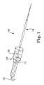
- FIG. 1is a perspective view of an expandable blood pump according to one embodiment of the present disclosure.
- FIG. 2is a schematic diagram of an expandable blood pump according to one embodiment of the present disclosure.
- FIG. 3is a perspective view of an impeller according to one embodiment of the present disclosure.
- FIG. 4Ais a perspective view of an impeller according to another embodiment of the present disclosure.
- FIG. 4Bis an end view of the impeller of FIG. 4A .
- FIG. 5Ais a perspective view of an impeller according to yet another embodiment of the present disclosure.
- FIG. 5Bis an end view of the impeller of FIG. 5A .
- FIG. 5Cis a perspective view of the impeller.
- FIG. 5Dis a side view of the impeller, showing a possible flow direction.
- FIG. 5Eis an alternate perspective view of the impeller, showing a possible rotational direction.
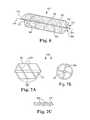
- FIG. 6is a perspective view of a cannula according to one embodiment of the present disclosure.
- FIG. 7Ais a side schematic view of the cannula embodiment of FIG. 6 in an expanded configuration.
- FIG. 7Bis an end schematic view of the cannula embodiment of FIG. 6 in the expanded configuration.
- FIG. 7Cis a side schematic view of the cannula embodiment of FIG. 6 in a collapsed configuration.
- FIG. 7Dis a perspective view of a cannula embodiment with support members formed of a wire braid.
- FIG. 7Eis a perspective view of a cannula embodiment with support members forming a tubular frame.
- FIG. 7Fis a side view of the tubular frame cannula embodiment.
- FIG. 8Ais a side schematic views of a cannula embodiment in an expanded configuration.
- FIG. 8Bis an end schematic view of the cannula embodiment of FIG. 8A .
- FIG. 8Cis a side schematic view of the cannula embodiment of FIG. 8A in a collapsed configuration.
- FIG. 9Ais a perspective view of a cannula according to still a further embodiment of the present disclosure having various diameters along its axial length.
- FIG. 9Bis a perspective view of a cannula with radial flow straighteners.
- FIG. 9Cis a perspective view of a cannula with concentric flow straighteners.
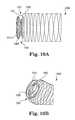
- FIG. 10Ais a side view of a cannula according to yet another embodiment of the present disclosure having a port fixation feature.
- FIG. 10Bis a perspective view of the cannula of FIG. 10A .
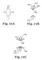
- FIG. 11Ais a side schematic view of an, opening in a wall between any combination of heart chamber(s) and blood vessel(s).
- FIG. 11Bis a side schematic view of the cannula embodiment of FIG. 10A fixed within the opening of FIG. 11A .
- FIG. 11Cis a side schematic view of the cannula embodiment of FIG. 10A fixed within the opening of FIG. 11A , wherein the opening also has an intermediate device fixed at the wall opening.
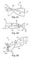
- FIG. 12is a perspective view of a catheter guidance system according to one embodiment of the present disclosure.
- FIG. 13is a perspective view of a catheter guidance system according to another embodiment of the present disclosure.
- FIG. 14includes a side view and exploded side views of a power transmission system of a pump according to one embodiment of the present disclosure.
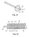
- FIG. 15is a perspective view of a power transmission system of a pump according to another embodiment of the present disclosure.
- FIG. 16is a perspective view of a power transmission system of a pump according to still a further embodiment of the present disclosure.
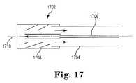
- FIG. 17is a perspective view of a power transmission system of a pump according to yet another embodiment of the present disclosure.
- FIG. 18is a flow diagram of a method of deploying and using and expandable blood pump according to one embodiment of the present disclosure.
- the present disclosurerelates to novel and advantageous blood pumps for cardiac support, including, but not limited to acute cardiac support and temporary cardiac support.
- the present disclosurerelates to novel and advantageous expandable blood pumps and methods of their deployment and use for quickly providing temporary circulatory support.
- Example uses of the various embodiments of expandable blood pumps provided hereincan range from contingency support during high risk cardiac surgery to immediate full support after a myocardial infarction.
- a pumpwith a cannula and impeller in a collapsed, deployment configuration, may be inserted into, for example, a major blood vessel and guided to the heart.
- the clinician or operatormay use catheter controls to expand the pump's cannula.
- the clinician or operatormay then expand the pump's impeller within the cannula; alternately, expansion of cannula and impeller may occur at the same time.
- Rotation of the impellergenerates blood flow within the cannula between the cannula's inlet and outlet.
- the cannulamay also provide separation between any surrounding tissue and the rotating impeller.
- the impellermay be driven via a power transmission system in the catheter and controlled from a control and/or power unit.
- the clinician or operatormay enter therapeutic system parameters into the control unit, which drives the pump at the desired speed.
- the collapsed, deployment configurationmay permit quick insertion to, and removal from, several anatomical positions while the expanded, operable configuration may permit appropriate therapy.
- the present disclosurein one embodiment, relates to expandable blood pumps and methods of their deployment and use for circulatory support.
- the blood pumpmay include a cannula constructed of an adjustable support member and flexible mesh cover allowing a deployment configuration of reduced or minimum collapsed size and an operable configuration of increased or maximum expanded size.
- the cannulamay vary in diameter along its axial length reducing or minimizing the interference between the expanded cannula and tissue openings.
- cannula diameter variationcan allow for a leading narrow portion of the cannula which can improve maneuverability and permit an increased reach in anatomy.
- cannula diameter variationcan allow for fixing the position of the pump with respect to a vessel opening or other port that it passes through.
- the cannulamay include multiple openings, which can assist in preventing zero flow if a tissue collapses at the inlet end of the cannula.
- the cannulain some embodiments, may be configured such that an outlet ejects flow generally perpendicularly to the pump's axis of rotation.
- the blood pumpmay be powered by a fluid system including catheter supply and return channels that cause a mechanical generator to rotate.
- the mechanical generatormay be mechanically or magnetically coupled to an impeller of the blood pump.
- the present disclosurein another embodiment, relates to a pump for inducing motion of a fluid relative the pump.
- the pumpmay include an elongated cannula having at least one section adjustable between an operable configuration having a first diameter and a deployment configuration having a substantially smaller diameter.
- the pumpmay also include an impeller positioned within the adjustable section of the cannula and rotatable therein about an impeller axis.
- the impellercan include a rigid or semi-rigid mast or flexible support member supporting a flexible web, the mast or support member being separately positionable with respect to the cannula between an operable configuration and a deployment configuration, the operable configuration extending at least a portion of the web to a first radial distance from the impeller axis and the deployment configuration collapsing the portion of the web to a second radial position of substantially shorter distance from the impeller axis.
- the cannulamay include a spiral support member, the spiral support member spiraling about the impeller axis.
- the spiral support membermay be adjustable from the operable configuration to the deployment configuration by twisting the spiral support member.
- the spiral support membermay be adjustable from the operable configuration to the deployment configuration by axially positioning a proximal and distal end of the spiral support member further away from one another.
- the cannulamay further include a cover supported by the spiral support member.
- the coverin some instances, may comprise a plurality of inlet openings and/or an outlet opening permitting flow to exit the pump substantially perpendicularly to the impeller axis.
- the cannulamay also include a second section adjustable between an operable configuration having a second diameter and a deployment configuration having a diameter substantially smaller than the second diameter.
- the cannulacan include a port fixation neck between the first and second cannula sections.
- the impellermay have two or more rigid or semi-rigid masts or flexible support members supporting the flexible web, the support members in the operable configuration being substantially perpendicular to the impeller axis and in the deployment configuration being substantially parallel to the impeller axis.
- a distal catheter sectionmay support a first one of the support members and a proximal catheter section may support a second one of the support members, at least one of the distal and proximal catheter sections being rotatable with respect to the other so as to radially offset the support members.
- a first end of the rigid or semi-rigid mast or flexible support membermay be operably connected with a first catheter section of the impeller and a second end of the rigid or semi-rigid flexible support member may be operably connected with a second catheter section, at least one of the first and second catheter sections being axially positionable with respect to the other, such that as the catheter sections are positioned toward each other, the support member is forced toward the operable configuration and as the catheter sections are moved away from each other, the support member is forced toward the deployment configuration.
- at least one of the first and second catheter sectionsmay be rotatable with respect to the other so as to radially offset the first and second ends of the support members.
- the pumpmay include a drive shaft for driving a rotating motion of the impeller.
- the drive shaftmay include a proximal section having a first gear at its distal end and a distal section having a second gear at its proximal end, rotation of the proximal section being transferred to the distal section by adjacently positioning the first and second gears.
- a power transmission system of the pump for driving a rotational motion of the impellermay include a mechanical generator for transferring fluid motion therethrough into rotational motion of the generator about the impeller axis and a first lumen driving fluid to the mechanical generator and a second lumen transferring fluid away from the mechanical generator.
- the mechanical generatormay be operably connected with the impeller, thereby transferring rotational motion of the generator about the impeller axis to rotational motion of the impeller about the impeller axis.
- the power transmission systemmay further include one or more first magnets radially positioned about the impeller axis and operably connected at or near a distal end of the mechanical generator and rotatable therewith about the impeller axis and a magnet housing operably connected with the impeller and positioned adjacent the distal end of the mechanical generator, the housing having one or more second magnets radially positioned about the impeller axis interacting with the first magnets to magnetically transfer rotational motion of the first magnets to rotational motion of the second magnets about the impeller axis.
- the present disclosurein yet a further embodiment, relates to a method of deploying a pump for cardiac support.
- the methodmay generally include providing a pump, such as that described above, inserting a catheter with the pump operably connected at or near the distal end thereof into a blood vessel with the cannula and impeller in their deployment configurations, guiding the pump to a desired location, and adjusting the cannula and impeller from their deployment configurations to their operable configurations.
- Methodsmay also include adjusting the rigid or semi-rigid mast or flexible support member and flexible web to create a desired impeller blade angle.
- the impellermay be driven at a desired speed via a power transmission system. Additional methods may include adjusting the cannula and impeller back to their deployment configurations and removing the catheter and pump from the blood vessel.
- FIG. 1illustrates one embodiment of an expandable blood pump 100 according to the present disclosure.
- an expandable blood pump 100may generally include a catheter 102 with a pump 104 positioned at or near the inserted end of the catheter and a control and/or drive unit 106 operably connected at or to an external end of the catheter.
- the pump 104may include an impeller 108 , a cannula 110 , and a guidance system 112 .
- the catheter 102may include a power transmission system operably coupling the pump 104 and the control and/or drive unit 106 .
- a power transmission systemoperably coupling the pump 104 and the control and/or drive unit 106 .
- these componentssuch as but not limited to, the impeller 108 , cannula 110 , guidance system 112 , and power transmission system, can have various embodiments, which may be interchanged or interchangeable within the blood pump 100 to create a variety of different blood pump embodiments, which will be understood from the following description.
- the various embodiments of impellers of the present disclosuremay include one or more impeller blades comprising a thin, flexible web or film of material suspended by or between one or more generally moveable, flexible, rigid or semi-rigid support members or masts.
- the impellermay be activated between a collapsed, deployment configuration and an expanded, operable configuration by changing the position of the moveable, rigid or semi-rigid support members, thereby stretching the flexible web into a desired position and creating an impeller blade surface. That is, by virtue of the flexible web and moveable, rigid or semi-rigid support members, the impeller may permit a collapsed, deployment configuration of reduced or minimum size and an expanded, operable configuration of increased or maximum size.
- the impellermay be activated between a collapsed, deployment configuration and an expanded, operable configuration separately from an activation of the cannula (discussed in further detail below) between a collapsed, deployment configuration and an expanded, operable configuration.
- expansion of cannula and impellermay occur together, at substantially the same time.
- the impeller blades' geometries and scalescan reduce hemolysis, thereby improving procedure outcomes due to improved therapy.
- the impellermay be located within the cannula at any axial distance from the distal tip.
- an impeller 300may be comprised of one or more impeller blades 302 , each blade having a flexible web 304 suspended between rigid or semi-rigid, cantilevered support members 306 attached to the catheter 308 .
- the support members 306may be rotated or adjusted between positions substantially parallel and perpendicular to the pump's rotational axis 310 .
- the flexible web 304With the support members 306 in a position substantially parallel to the pump's rotational axis 310 , the flexible web 304 may be retracted therewith to a collapsed, deployment configuration.
- the flexible web 304may be extended therewith to an expanded, operable configuration.
- the catheter 308may include a catheter layer having a proximal section 312 and a distal section 314 , which may be rotated relative one another.
- Each blade 302may have a support member 306 positioned at the proximal section 312 and a support member at the distal section 314 .
- the angle of the flexible web, and thus the impeller blade surfacemay be created or modified by rotation of the proximal 312 and distal 314 sections of the catheter 308 relative one another.
- an impeller 400may include a flexible web 402 suspended by or between a generally semi-rigid, but flexible support member 404 and optionally the catheter 406 .
- the generally semi-rigid, but flexible support member 404may be but is not limited to a moderate stiffness wire, and may be attached at both ends 408 , 410 to the catheter 406 .
- the catheter 406may include a sliding section 412 and a rotational section 414 , which may be rotated relative to the sliding section, and the support member 404 may be attached at both ends 408 , 410 to the sliding section of the catheter.
- a portion of the support member 404may also be generally held in place axially at a fixed location 416 along the rotational section 414 .
- the flexible support member 404may pass through the rotational section 414 , as shown in FIG. 4A , such that a portion of the support member is generally held in place axially at fixed location 416 along the rotational section.
- the support member 404may be split into two sections, each section having an end attached to the sliding section 412 and an end attached to the rotational section 414 at fixed location 416 .
- other suitable elements for permitting proximal and distal ends of the flexible support member 404 to move axially relative one anotherare considered within the spirit and scope of the present disclosure.
- the support wiremay be round or flat.
- the supportsmay be formed from a cut tube, hollow wire, or similar structure.
- the sliding section 412 of the catheter 406may be slid or axially adjusted along the rotational section 414 between axial positions toward and away from fixed location 416 . With the sliding section 412 slid to a position generally relatively away from fixed location 416 , portions of the support member 404 may be pulled closer to the pump's rotational axis 418 , thereby causing the flexible web 402 to be retracted therewith to a collapsed, deployment configuration.
- portions of the support member 404may be forced away from the pump's rotational axis 418 , thereby causing the flexible web 402 to be expanded therewith to an expanded, operable configuration, as illustrated in FIG. 4A .
- the angle of the flexible web, and thus the impeller blade surfacemay be created or modified by rotation of the rotational section 414 of the catheter 406 with respect to the sliding section 412 , as illustrated in FIG. 4B .
- an impeller 500may include one or more impeller blades 502 , which may each include a flexible web 504 suspended by or between a generally semi-rigid, but flexible support member 506 and optionally the catheter 508 .
- the generally semi-rigid, but flexible support member 504in some embodiments, may be but is not limited to a moderate stiffness wire, and may be attached at both ends 510 , 512 to the catheter 508 .
- the catheter 508may include a catheter layer having a proximal (alternatively, distal) section 514 and a distal (alternatively, proximal) section 516 , with either or both sections axially positionable along the pump's rotational axis 518 and either or both sections rotatable about the pump's rotational axis, such that the distal and proximal sections may be axially positioned and rotated relative to one another.
- the support member 506may be attached at one end 510 to the distal section 514 and at one end 512 to the proximal section 516 , thereby permitting the ends to also be axially positioned and rotated relative one another by means of the distal and proximal sections.
- Other suitable elements for permitting distal 510 and proximal 512 ends of the flexible support member 506 to move axially and/or rotationally relative one anotherare considered within the spirit and scope of the present disclosure.
- the impeller geometrymay be characterized by a blade angle ( ⁇ 1 ) at the inlet that will be sharper (more perpendicular and less parallel to the axis of rotation) and a blade angle ( ⁇ 2 ) at the outlet that will be flatter (more parallel to the axis of rotation).
- the transition between the two anglesmay occur gradually, in order to improve flow performance and reduce turbulence and other losses.
- the blade angle ( ⁇ )may be measured between the direction of axis (or rotational axis) 518 and a tangent line 519 to the impeller blade 502 , as shown in FIG. 5B , where the tangent line 519 is defined at the radially outer portion of the web 504 , or along flexible support 506 .
- the inlet or proximal blade angle ( ⁇ 1 )may be relatively larger toward the proximal or inlet section 516 of impeller 500 ; that is, with the blade edge or tangent line along flexible support 506 or the outer portion of web 504 oriented more or less perpendicularly to the direction of axis 518 .
- outlet or distal blade angle ( ⁇ 2 )may be relatively smaller ( ⁇ 2 ⁇ 1 ) toward distal or outlet section 514 ; that is, with the blade edge or tangent along flexible support 506 or the outer portion of web 504 oriented more or less parallel to or along the direction of axis 518 .
- the value of the blade angle ( ⁇ )may be substantially continuous, with a substantially continuous (e.g., first) derivative between distal end 514 and proximal end 516 of axial member or catheter 508 . Further, the blade angle may vary from approximately perpendicular or somewhat less than perpendicular toward the proximal end 516 (that is, ⁇ 1 ⁇ 90°), to approximately parallel or somewhat greater than parallel toward the distal end 514 ( ⁇ 2 ⁇ 0°). Alternatively, the blade angle ( 0 ) may vary between upper and lower bounds, or both, for example ⁇ 10°, ⁇ 20°, or ⁇ 30°; and/or ⁇ 80°, ⁇ 70°, or ⁇ 60°.
- proximal 516 and distal 514 sections of catheter 508may also be reversed, so that ⁇ 1 > ⁇ 2 .
- direction of flow F(arrow 520 ) may proceed in either direction along impeller 500 , from end 514 toward end 516 or from end 516 toward end 514 , without loss of generality.
- the blade angle ( ⁇ )may be substantially constant along impeller 500 , such that ⁇ 1 ⁇ 2 , or the blade angle ( ⁇ ) may increase or decrease substantially monotonically between ⁇ 1 and ⁇ 2 , where ⁇ 1 ⁇ 2 .
- the variationmay be linear as a function of axial position z.
- the blade angle ( ⁇ )may also vary exponentially, or take another functional form.
- the blade angle ( ⁇ )may also have local minima and maxima between ⁇ 1 and ⁇ 2 .
- Either or both of the distal 514 and/or proximal 516 sections of the catheter 508may be slid or axially adjusted along the pump's rotational axis 518 between axial positions toward and away from the other. With the distal 514 and proximal 516 sections adjusted to a position generally relatively away from each other, portions of the support member 506 may be pulled closer to the pump's rotational axis 518 , thereby causing the flexible web 504 to be retracted therewith to a collapsed, deployment configuration.
- portions of the support member 506may be forced away from the pump's rotational axis 518 , thereby causing the flexible web 504 to be expanded therewith to an expanded, operable configuration, as illustrated in FIG. 5A .
- the angle of the flexible web, and thus the impeller blade surfacemay be created or modified by rotation of either or both of the distal 514 and/or proximal 516 sections of the catheter 410 with respect to one another, as illustrated in FIG. 5B .
- Rotation of the impeller 500 in or along an operational direction Rmay be a mechanism for impeller 500 to deploy and expand, utilizing fluid flow, pressure, bias, centrifugal force, or a combination thereof to spread webs 504 in a radially outward position with respect to rotational axis 518 ; that is, with blades 502 in an operable position outward of catheter 508 .
- Rotation in the opposite directionmay cause the mechanism to collapse, with blades 502 positioned closer to catheter 508 , and webs 504 gathered into a more radially inward position with respect to axis 518 .
- the operational direction of rotation Rmay be from a relatively higher pressure surface of blade (or blade pair) 522 toward a relatively lower pressure surface of blade (or blade pair) 522 , as shown in FIG. 5E .
- web 504also flexes under load to generate a substantially concave pressure surface along one side of blade 502 (e.g., 502 A) and a substantially convex suction surface along the opposite side or blade 502 (e.g., 502 B).
- the operational direction or curvature (or both)may be reversed, based on flow conditions and the power or torque supplied to impeller 500 .
- the flexible webs of the various embodiments of cannulas described abovemay be manufactured from any suitable materials.
- the various embodiments of cannulas described abovemay be manufactured from, but are not limited by, a polymer, a metal or metal alloy, a shape memory material, or combinations of materials.
- the material of webs 504may also be a woven mesh attached to the support members 506 , such as a Nitinol or fabric weave.
- the meshmay be left with openings for improved flow dynamics, and the mesh may be coated. Where a coating is used, the coating may be silicone or polyurethane (PU).
- the support members or masts 506may further be formed of or comprise straight or curved wire, braided wire or tubing, for example laser cut tubes or laser cut tubing.
- One or both of web 504 and support members 506may also be formed of or include an additional cover material, for example (expanded) polytetrafluoroethylene (ePTFE or PTFE), high density polyethylene (HDPE or PEHD), polyethylene terephthalate (PET or PETE), or a polyimide or silicone material.
- ePTFE or PTFEpolytetrafluoroethylene
- HDPE or PEHDhigh density polyethylene
- PET or PETEpolyethylene terephthalate
- a polyimide or silicone materialfor example (expanded) polytetrafluoroethylene (ePTFE or PTFE), high density polyethylene (HDPE or PEHD), polyethylene terephthalate (PET or PETE), or a polyimide or silicone material.
- ePTFE or PTFEpolytetrafluor
- the various embodiments of cannulas of the present disclosuremay include a plurality of support members or ribs, and may be activated between a collapsed, deployment configuration and an expanded, operable configuration by changing the relative position of the ribs.
- the cannulamay be activated between a collapsed, deployment configuration and an expanded, operable configuration separately from an activation of the impeller between a collapsed, deployment configuration and an expanded, operable configuration.
- a conduitmay be created within which the pump's impeller may be expanded and operated. Operation of the impeller can generate blood flow within the cannula between the cannula's inlet and outlet, which may typically be provided at the proximal and distal ends, respectively, of the cannula. In some embodiments, the cannula may also provide separation between any surrounding tissue and the impeller.
- a cannula 600may include a thin, flexible film or mesh cover 602 supported by or between one or more substantially rigid or semi-rigid support members 604 in spiral configuration, creating a plurality of ribs 606 .
- the ribs 606may stretch and/or support the cover 602 to create a conduit 608 , in which the impeller (e.g., impeller 500 as shown in FIG. 6 ; although any of the above described impellers are suitable) may by expanded to its operable configuration.
- the impellere.g., impeller 500 as shown in FIG. 6 ; although any of the above described impellers are suitable
- the substantially rigid or semi-rigid support members 604 in spiral configurationmay be biased to the expanded, operable configuration.
- the cannula 600may be adjusted from an open or operational configuration, as shown in FIGS. 7A and 7B , to a collapsed, deployment or insertion configuration, as illustrated in FIG. 7C .
- the catheter 610may include a catheter layer having a distal section 612 and a proximal section 614 , with either or both sections axially positionable along the pump's rotational axis 616 , such that the distal and proximal sections may be axially positioned relative to one another.
- the cannula 600may be attached at one end 618 to the distal section 612 and at one end 620 to the proximal section 614 , thereby permitting the ends of the cannula 600 , or support members 604 , to also be axially positioned relative one another by means of the distal and proximal sections.
- the cannula 600may be adjusted from an open configuration to a collapsed, deployment configuration by causing the support members 604 to be adjusted axially generally relatively away from each other, thereby causing portions of the support members to be pulled closer to the pump's rotational axis 616 , and causing the flexible mesh cover 602 to be retracted therewith.
- either or both of the distal 612 and proximal 614 sectionsmay be rotatable about the pump's rotational axis 616 , such that the distal and proximal sections may be rotated relative to one another.
- the ends of the cannula 600 , or support members 604may additionally or alternatively be rotatably positioned relative one another by means of the distal 612 and proximal 614 sections.
- the cannula 600may be adjusted to a collapsed, deployment configuration by additionally or alternatively causing the ends of the spiral support members 604 to be rotated relative one another other, thereby shrinking the size of the conduit 608 and collapsing the mesh cover 602 supported there between.
- cannula 600 and/or catheter 610may include a drawstring, which may be pulled to gather up any loose material of the retracted mesh cover 602 and hold the mesh cover relatively closer to the catheter body.
- the support members 604 and ribs 606may be formed from a wire frame or braid or a laser-cut shape memory tube, as shown in FIGS. 7D and 7E .
- the patternmay also be reversed, with a circumferential or helical braided or mesh pattern of support members 604 or ribs 606 on the ends, and a substantial straight and axial or longitudinal pattern of support members 604 or ribs 606 in between.
- the rib pattern 606is formed from a laser cut tube support member 604
- the geometrymay also be provided without or substantially without projections, for example without sharp projections that could snag on a sheath or similar element that may be provided over the cannula 600 , or which could ride over the cannula 600 in the collapsed or deployment configuration.
- FIG. 7Fis a side view of cannula 600 in a tubular frame embodiment.
- cannula 600includes a support structure, formed of substantially straight and axially aligned ribs 606 extending from proximal end or region 614 to distal end or region 612 , with at least one cross-bracing structure 607 in intermediate or middle region 613 , between ends 612 and 614 .
- the support structures 606 and 607 of cannula 600may for formed, for example, by laser cutting from a memory metal such as a Nitinol tube, or using another suitable material as described herein.
- a memory metalsuch as a Nitinol tube
- FIG. 7Fmay be formed similarly to the embodiment of FIG. 7E , with cross-brace structure 607 formed in a sinusoidal, sawtooth or stent-like pattern for added circumferential strength in mid region 613 .
- cross-brace 607may be formed of one or more helical or circumferential ribs, as described above.
- Support ribs 606are fixed or attached to catheter 610 at one end, for example first end 620 of proximal region 614 .
- the opposing ende.g., second end 618 of distal region 612 ) floats in the axial dimension with respect to catheter 610 and proximal end 620 .
- support members 606 and 607may be biased to expand into their operational form, with longitudinal ribs 606 extending radially and axially from first end 620 into proximal region 614 , substantially axially from proximal region 614 through mid region 613 and into distal region 612 , and axially and radially from distal region 612 to second end 618 .
- Cross brace structure 607expands substantially circumferentially and radially to support mid region 613 of cannula 600 , as described above.
- Mesh cover 602may be formed of ePTFE or polyurethane, as described above, or of another suitable fabric material, or of silicone.
- second (free end) 618will typically slide or reposition toward first (fixed) end 610 , opening cannula 600 and mesh 602 up in the radial direction for deployment and operation.
- Support members 606 and 607deform from the deployment state into the operational state, expanding mesh or cover 602 to form a flow passage for impeller 500 .
- support members 606 and 607 and mesh 602are covered by sheath 622 , deforming back from the operational state into the deployment state for removal.
- Impeller 500may be formed with blades supported by a memory metal such as Nitinol wires 501 covered with a mesh or web material to form blades 502 , as described above, with blades 502 and wires 501 fixed to drive shaft 630 on proximal end 532 of blades 502 and impeller 500 .
- Distal end 531 of impeller 500 and blades 502floats in the axial dimension with respect to proximal end 532 .
- support members 607 and 606are biased into their operational form and distal (free) end 531 of impeller 500 slides or displaces axially toward the proximal (fixed) end 532 .
- Stop 632may be provided on drive shaft 630 in distal region 612 to prevent over-travel of free impeller end 531 , for example between free end 531 and distal end 618 of cannula 606 .
- Suitable cover materials for impeller 500 and blades 502include silicone, polyurethane, biologically suitable fabric materials, wire mesh, and cut metal sheet, and combinations thereof, for example with one material selected for use as a structural form and another selected for use as coating or web.
- Drive shaft 630may be formed of a flexible wire coil in at least a portion of proximal region 614 , for example until drive shaft 630 reaches impeller 500 at proximal end 532 .
- Drive shaft 630may be formed of a substantially straight or semi-rigid wire in mid region 613 and distal region 612 , for example from proximal end 532 through distal end 531 , stop 632 and distal end 618 of cannula 600 .
- proximal region 614drive shaft 630 is supported by catheter 610 at end 620 .
- drive shaft 630In distal region 612 , drive shaft 630 may be supported by a short section of catheter at distal end 618 of cannula 600 , where distal end 618 is supported by structural members 606 and 607 .
- longitudinal supports 606include radially and axially extending portions 606 A in proximal and distal regions 614 and 612 , and substantially axially extending regions 606 B in mid section 613 , between proximal and distal regions 614 and 612 .
- drive shaft 632may extend from first (proximal) end 620 of cannula 600 at catheter 610 through proximal region 614 , mid region 613 with impeller 500 , and distal region 612 with stop 632 to second (distal) end 618 .
- cannula 600is axially and radially fixed to catheter 610 at proximal end 620 via radial and axial load supporting portions 606 A of supports 606 , in proximal region 614 .
- distal end 618may slide along drive shaft 630 to provide freedom of motion in the axial direction with respect to proximal end 620 , as described above.
- distal end 618 of cannula 600may be radially fixed with respect to drive shaft 630 , with axial freedom of motion provided by sliding drive shaft axially within catheter 610 .
- sheath 622is configured to push over and back over the ful axial length of cannula 600 , in both proximal (opening) and distal (collapsing) direction, without binding.
- proximal end 620 of cannula 600may be configured to slide axially with respect to catheter 610 and (fixed) distal end 618 , so that cannula 600 may be deployed or collapsed by distal and proximal axial motion of drive shaft 630 with respect to catheter 610 and (e.g., axially stationary) sheath 622 , where drive shaft 630 is axially fixed to cannula 630 at distal end 618 , as described above.
- axial motion of drive shaft 630could also be utilized to collapse and deploy impeller 500 , in combination with cannula 600 , where impeller 500 would collapse and deploy within cannula 600 , and cannula 600 would collapse and deploy as proximal end 620 is drawn into or extended out from (e.g., axially stationary) sheath 622 .
- cannula 600 and catheter 610may also be provided with fixing elements to position or retain pumping system 100 with respect to an anatomical element, for example a vascular wall, valve, or anatomical feature of the heart.
- an anatomical elementfor example a vascular wall, valve, or anatomical feature of the heart.
- a screw or other mechanical retainer or coupling element 652may be provided at the tip of pump system 100 , for example on the catheter section of distal end or tip 618 of cannula 600 , in order to secure cannula 600 and pump system 100 to a cardiac wall.
- one or more hook or tine-type mechanical retainers 652may be provided, for example as configured to deploy in combination with cannula 600 , in order to attached to a trebecula or similar trabeculation formation within a chamber of the heart, or a similar feature on the cardiac wall.
- One or more retainers 652may also be provided as a guidewire anchor to attach or anchor the guidewire, as described below, where pump system 100 is positioned by running out over the guidewire and into a desired anchor location.
- one or more balloons or other expansion elements 654may be provided outside of cannula 600 , in order to secure pump 100 to a vascular feature such as a valve or aorta wall.
- Balloon elements 654may expand by action of a biasing element, as described above, or through fluid pressurization, for example as provided by pump 100 or via an additional channel or lumen, for example as coupled to a fluid drive system, as described below.
- Balloon elements 654may be provided in any combination of proximal, mid and distal regions 614 , 613 and 612 of cannula 600 . Balloon elements 654 may also be provided along catheter 610 or sheath 622 , in order to secure catheter 610 to an aorta wall or other vascular structure.
- a cannula 800may include a thin, flexible film or mesh cover 802 supported by or between one or more substantially rigid or semi-rigid support members 804 in a linear, axial configuration, creating a plurality of ribs 806 that are generally aligned parallel to the catheter body.
- the ribs 806may stretch and/or support the cover 802 to create a conduit 808 , in which the impeller may by expanded to its operable configuration.
- the substantially rigid or semi-rigid support members 804 in a linear, axial configurationmay be biased to the expanded, operable configuration.
- the cannula 800may be adjusted to a collapsed, deployment configuration, as illustrated in FIG. 8C .
- the catheter 810may include a catheter layer having a distal section and a proximal section, with either or both sections axially positionable along the pump's rotational axis 812 , such that the distal and proximal sections may be axially positioned relative to one another.
- the cannula 800may be attached at one end 814 to the distal section and at one end 816 to the proximal section, thereby permitting the ends of the cannula 800 , or support members 804 , to also be axially positioned relative one another by means of the distal and proximal sections.
- the cannula 800may be adjusted to a collapsed, deployment configuration by causing the support members 804 to be adjusted axially generally relatively away from each other, thereby causing portions of the support members to be pulled closer to the pump's rotational axis 812 , and causing the flexible mesh cover 802 to be retracted therewith.
- the cannula 800may be opened to an expanded or operable configuration by causing the support members 804 to be adjusted axially generally relatively toward one another, thereby causing portions of the support members to be positioned away from the pump's rotational axis 812 , and causing the flexible mesh cover 802 to be expanded or deployed therewith. This may be accomplished, for example, by relative axial positioning of the proximal 816 and distal 814 ends of cannula 800 , or the corresponding proximal and distal portions of catheter 810 .
- cannula 800 and/or catheter 810may include a drawstring, which may be pulled to gather up any loose material of the retracted mesh cover 802 and hold the mesh cover relatively closer to the catheter body.
- collapse of the cannula 800may also cause the impeller to collapse to the deployment position, and expansion or deployment of the cannula 800 may also allow the impeller to expand from the collapsed deployment position and to open outward to an operable or deployed position.
- the cannulamay have a generally constant diameter axially along the catheter body.
- the cannula 900may have a diameter that varies axially along the catheter body 902 .
- the cannula 900may have two or more axial sections 904 , 906 of substantially constant diameters and one or more axial sections of transition 908 from one section of constant diameter to a different section of constant, but different, diameter.
- An impellersuch as those described above, may be provided in any suitable axial section.
- an impellere.g., impeller 500 as shown in FIG. 9A ; although any of the above described impellers are suitable
- an impellermay be provided within a proximal axial section 906 of relatively larger diameter than a distal axial section 904 .
- the transition from a relatively larger diameter conduit to a relatively smaller diameter conduitmay also increase the rate of flow through the distal axial section 904 and out of cannula 900 .
- operation of an impeller within the various embodiments of cannulas described hereinmay cause a flow of fluid, e.g., blood, into an inlet opening at one end of the cannula, through the cannula, and out an outlet opening at an opposite end of the cannula.
- a flow of fluidmay be substantially axial with the axis of rotation of the impeller.
- a cannula 900may additionally, or alternatively include inlet 911 or outlet openings 909 that permit the flow of fluid in or out of the cannula 900 , substantially perpendicularly to the axis 918 of rotation of the impeller.
- a cannulamay include multiple inlets 911 , for example in the inlet section or proximal axial section 906 of cannula 900 , and/or multiple outlets 909 , for example in the outlet section or distal axial section 904 of cannula 900 , which may assist in preventing blockages of the inflow and/or outflow of fluid to or from the pump.
- the cannula 900 and other devices described hereinmay also utilize flow straighteners, for example flow straighteners 916 as shown in FIGS. 9B and 9C .
- Flow straighteners 916may be comprised of one of more flexible membranes that extend radially from the catheter 910 to the cannula 900 ( FIG. 9B ), or longitudinally along the axis 918 of flow passage 920 between the catheter 910 and the cannula 900 ( FIG. 9C ), or a combination thereof.
- Flow straighteners 916thus divide flow passage 920 between catheter 910 and cannula 916 into a number of radially or concentrically divided channels.
- flow straighteners 916have a rectangular, square, triangular or hexagonal channel configuration, or another design.
- Flow straighteners 916may also be utilized in combination with additional inlet and outlet holes, aperture or ports 909 and 911 , as described above.
- Flow straighteners 916redirect swirl and other non-axial flow that is moving rotationally or circumferentially through passage 920 to axial flow, moving substantially along axis 918 through the different channels formed along flow passage 920 .
- Flow straighteners 916may be located along or across the proximal (inlet) end 914 of cannula 900 and catheter 910 , along or across the distal (outlet) end 912 of cannula 900 and catheter 910 , or at both ends 914 and 912 .
- a cannula 1000may include one or more features 1002 for port fixation. More specifically, as shown in cross-section in FIG. 11A , where there is an opening 1102 in the wall 1103 , for example but not limited to, between any combination of heart chamber(s) and blood vessel(s), the cannula 1000 may be configured such that it can be placed in the opening, expanded as described in various manners above, and remain substantially affixed with respect to the opening by means of the one or more features 1002 for port fixation, as illustrated in cross-section in FIG. 11B .
- one end of the cannula 1000may include an impeller conduit section 1006 , a neck section 1008 , and a port fixation section 1010 .
- the cannula 1000including the impeller conduit section 1006 , neck section 1008 , and a port fixation section 1010 , may be adjusted between a collapsed, deployment configuration and an expanded, operable configuration.
- the neck section 1008may be configured to expand to a diameter that is smaller than the expanded diameter of the impeller conduit section 1006 and the port fixation section 1010 , thereby forming a generally hourglass shape having a pocket 1012 created between the impeller conduit section and the port fixation portion at the neck section.
- the cannula 1000may be expanded at a position such that the pocket 1012 formed at the neck section 1008 upon expansion of the cannula may generally align with the wall opening 1102 .
- the relatively larger diameters of the impeller conduit section 1006 and the port fixation section 1010can be designed such that they do not easily pass through the wall opening 1102 when the cannula is in the expanded, operable configuration, and thus cause the cannula 1000 to remain substantially affixed with respect to the opening by means of the pocket 1012 .
- an intermediate device 1104such as a port or similar device, may be fixed at the wall opening 1102 to, for example only, improve the opening strength and/or improve the opening geometry.
- the flexible film or mesh covers of the various embodiments of cannulas described abovemay be manufactured from any suitable materials, such as but not limited to a polymer, a metal or metal alloy, a shape memory material, or combinations of such materials.
- the various cannulas described abovemay be provided without flexible film or mesh covers, thereby leaving the support members exposed.
- different cover or structural support materialsmay be provided, including, but not limited to: PTFE or ePTFE, HDPE or PEHD, PET or PETE, PU, polyimide, silicone materials, and combinations thereof.
- the pump and impeller mechanisms, and the corresponding cannula and flow passage and channel structuresmay also be fixed in anatomical position by a catheter support, by the cannula resting against a vessel wall or valve 1103 , by a guidance feature resting against the internal or external anatomical structure of a heart, vein, artery, or blood vessel, by a coil anchor, or by inflating a balloon, for example between the cannula and a vessel wall, valve, or other anatomical structure 1103 , as described above.
- the various embodiments of impellers and cannulas described in the present disclosuremay be adjusted, for example to expand and retract the impellers and/or cannulas between the expanded, operable configuration and collapsed, deployment configuration, using a plurality of concentric layers or sheaths of the catheter, as will be described in further detail below.
- the plurality of concentric layersmay include a drive shaft layer, translatable along the catheter's axial direction for adjusting the impeller, and a cannula sheath, translatable along the catheter's axial direction for adjusting the cannula.
- the drive shaft layer and/or the cannula sheathmay be rotatable about the axis of rotation, so as to permit, for example, variation in impeller blade angle and/or to assist in, for example, collapsing a spiral support member, flexible support member, flexible mesh or flexible mesh or support element cover, as described above.
- the various embodiments of pumps disclosed hereinmay include a guidance system for directing the catheter and pump into and through the vasculature to the desired anatomical position, for example, at the heart.
- Suitable guidance systemsmay include an opening or passageway 1202 through or along the central axis 1204 of the catheter 1206 , such that the catheter and pump 1208 may be inserted over and travel along a guidewire 1210 as will be understood by those skilled in the art.
- a guidance system for directing the catheter and pump into and through the vasculature to the desired anatomical positionmay include a steerable catheter tip 1302 .
- the catheter 1304may include a generally flexible section 1306 at or near its distal end.
- the flexible section 1306may have an adjustable curvature that permits the flexible section of the catheter to be adjusted to aim the catheter in the desired direction of travel.
- the flexible section 1306may have a bias for curvature in a predetermined direction, or in some embodiments may have a bias for no curvature.
- the flexible section 1306may include a cable therewithin and anchored thereto for controlling the curvature of the flexible section, the cable running through the catheter to an external control system.
- the cableis anchored at or near the tip 1308 of the flexible section 1306 , which may permit ease of control.
- the cablemay be used to control the flexible section 1306 by, for example, manipulating or pulling the cable at the external control system to cause a desired curvature of the flexible section. Similarly, when the cable is manipulated in a different direction or released, the flexible section 1306 may return to its normal biased position.
- placement aidssuch as radio opaque marks, could be included near the pump or in other locations to assist in placement via fluoroscopy or other imaging technique.
- placement aids, markers, or tagscould be included in or provided on one or more of the pump, cannula, catheter, impeller or other structural element.
- the various embodiments of pumps disclosed hereinmay include a power transmission system in the catheter for driving the impeller
- the transmission systemmay be controlled, for example, from a control and/or power unit operably connected at or to an external end of the catheter.
- the power transmission systemmay generally provide for transferring power from the external control and/or power unit to the mechanical power needed by the pump or impeller.
- the transmission systemmay include a drive shaft that connects the impeller directly with a drive motor of the control and/or power unit through a clutch.
- the catheter 1402may include a plurality of concentric layers. In one such embodiment, these layers in order of innermost to outermost, may include but are not limited to, a cable 1404 , an inner catheter sheath 1406 , a rotatable layer 1408 of the drive shaft, a drive shaft layer 1410 that is axially positionable with respect to the rotatable layer 1408 and may, in some embodiments, be rotatable therewith, and an axially positionable cannula sheath 1412 .
- the cable 1404may be used, for example, to control the guidance system, such as a steerable catheter tip, described above; however, in other embodiments, the cable 1404 may be eliminated leaving a passageway for a guidewire along which the catheter travel may travel.
- the inner catheter sheath 1406may surround the cable 1404 .
- the rotatable drive shaft layer 1408may provide the rotational motion for the impeller and transfer the rotational motion thereto.
- the drive shaft layer 1410which is axially positionable with respect to the rotatable layer 1408 , may be used, as described above, to retract and deploy any of the impeller embodiments of the present disclosure.
- the cannula sheath 1412may be axially positionable with respect to the inner catheter sheath 1406 and may be used, as described above, to retract and deploy any of the cannula embodiments of the present disclosure.
- the outer sheath 1406may include an embedded braid or other structural element to increase torque transfer, or a coil to improve kink resistance, or both.
- the drive shaft layers 1408 , 1410may be longitudinally flexible, but torsionally rigid, thereby permitting the drive shaft to have flexibility when be maneuvered through the vasculature, but maintaining ability for delivering rotational motion.
- the drive shaft and drive shaft layers 1408 , 1410may be constructed of a single or multi-filar coil (or thread or fiber) construction.
- the hollow center of a catheter elementfor example inner catheter sheath 1406 or drive shaft layer 1408 or 1410 , could allow a guidewire to pass. There could also be a short rigid section to attach the pump.
- One or both of the drive shaft layers 1408 , 1410may be lubricated with a lubricating fluid, such as but not limited to saline.
- a lubricating fluidsuch as but not limited to saline.
- the constructionmay also use low friction coatings, such as Teflon, between relatively moving or rotating layers or elements, for example sheath layers, guide wires, cables, and shaft layers.
- the rigid sectionmay further be supported by mechanical bearings, such as ball, hydrodynamic or plain bearings.
- the rotatable drive shaft layer 1408 or both drive shaft layers 1408 , 1410as thus described, may be used to control the pump by delivering or transferring rotational motion to the impeller.
- the transmission systemmay include drive shaft element generally configured as that described above, except that at one or more locations along the drive shaft, a set of gears 1502 may be employed to permit relatively sharper bends or angles in the drive shaft between a distal drive shaft section 1504 and a proximal drive shaft section 1506 , while maintaining torque along the drive shaft.
- the drive shaft sections 1504 , 1506 , with gears 1502 at their adjacent endscan be brought into contact with one another or maintain contact with one another via tensioning element, such as but not limited to a cable or sheath.
- the angle between the drive shaft sections 1504 , 1506may be adjustable.
- the transmission systemmay include a fluid driven or hydrostatic transmission system 1602 in combination with a magnetic coupling device 1604 .
- an external systemmay drive a fluid to a mechanical generator, causing rotational motion of the mechanical generator, which is transferred to the impeller via a magnetic couple.
- the hydrostatic transmission system 1602may include a catheter body or outer sheath 1606 and an inner sheath 1608 , concentrically positioned within the outer sheath, the distal ends of which are operably connected with a mechanical generator 1610 .
- the inner sheath 1608may provide an inlet channel or lumen by which to deliver fluid from the external system to the mechanical generator 1610 , while the outer sheath 1606 may provide an outlet channel or lumen by which to return fluid from the mechanical generator to the external system; of course, in other embodiments, the outer sheath may provide the inlet channel while the inner sheath may provide the outlet channel.
- the mechanical generator 1610may convert the axial motion of the fluid passing therethrough to rotational motion of the generator about the central axis 1612 of the catheter.
- the generatormay include a proximal end of the magnetic coupling device 1604 , including one or more magnets 1614 .
- the magnets 1614may, by means of the rotational motion of the generator, also rotate therewith about the central axis 1612 of the catheter, creating a changing magnetic field at the distal end of the mechanical generator 1610 .
- Positioned at or near the distal end of the hydrostatic transmission system 1602may be the distal end of the magnetic coupling device 1604 having a housing 1616 also including one or more magnets 1618 which interact with the magnets 1614 of the proximal end of the magnetic coupling device to cause rotational motion of housing 1616 . More specifically, the changing magnetic field created by the rotational motion of magnets 1614 of the proximal end of the magnetic coupling device 1604 interacts with the magnets 1618 in housing 1616 causing rotational motion thereof.
- An impeller 1620such as any of the various embodiments of impellers described herein, may be operably connected with the distal end of the magnetic coupling device 1604 or housing 1616 and thus rotate therewith.
- One advantage of such fluid driven or hydrostatic transmission system 1602 in combination with a magnetic coupling device 1604is impeller interchangeability since the indirect connection provided by the magnetic coupling device between the transmission system and the impeller provides a relatively easy interconnect for changing between impeller embodiments.
- the transmission systemmay simply include a fluid driven or hydrostatic transmission system 1702 driving an operably connected impeller.
- an external systemmay drive a fluid to a mechanical generator, causing rotational motion of the mechanical generator, which is transferred substantially directly to the impeller.
- the hydrostatic transmission system 1702may include a catheter body or outer sheath 1704 and an inner sheath 1706 , concentrically positioned within the outer sheath, the distal ends of which are operably connected with a mechanical generator 1708 .
- the inner sheath 1706may provide an inlet channel or lumen by which to deliver fluid from the external system to the mechanical generator 1708 , while the outer sheath 1704 may provide an outlet channel or lumen by which to return fluid from the mechanical generator to the external system; of course, in other embodiments, the outer sheath may provide the inlet channel while the inner sheath may provide the outlet channel.
- the mechanical generator 1708may convert the axial motion of the fluid passing therethrough to rotational motion of the generator about the central axis 1710 of the catheter.
- the mechanical generator 1708may be directly connected to the impeller, such as any of the various embodiments of impellers described herein; however, it is recognized that any suitable elements for indirectly or operably connecting the mechanical generator 1708 and impeller, such as but not limited to a gearing system, are within the spirit and scope of the present disclosure.
- a fluid driven or hydrostatic transmission systemmay be externally connected with, for example, a hydraulic connector or compressible tube, which mates the fluid driven or hydrostatic transmission system to an external controller for driving the fluid, as will be understood by those skilled in the art.
- the external controllermay or may not be a component of the control and/or power unit, described herein.
- the transmission systemmay be electrically driven.
- the impellersuch as any of the various embodiments of impellers described herein, may be operably connected with a motor at or near the pump end of the catheter.
- An electrical systemmay be driven by the control and/or power unit operably connected at or to an external end of the catheter and may condition the energy for use in controlling the motor and rotating the impeller, as will be recognized by those skilled in the art.
- the electrical systemmay be located at or near the motor or may be positioned at any other suitable location, including but not limited to at the control and/or power unit operably connected at or to an external end of the catheter.
- the electrical system and control and/or power unitmay be operably connected by means of electrical connectors or conductors.
- a catheter with a pump at or near the distal end thereofmay be inserted into a major blood vessel and guided to the desired location, such as at the heart.
- the pumpmay include an impeller and cannula, and the impeller and cannula may be initially inserted in a collapsed, deployment configuration.
- the impeller and cannulamay be biased in the deployment configuration, or alternatively, may be retracted to the deployment configuration using a control unit operably coupled at or near the external end of the catheter.
- the clinician or operatormay use the control unit to adjust the pump's cannula, as described above, to an expanded, operable configuration, thereby creating a conduit for pump flow.
- the clinician or operatormay adjust the pump's impeller within the cannula into its expanded, operable configuration.
- the adjustment of the cannula and impeller into their expanded, operable configurationsmay be done substantially simultaneously.
- the impeller blade anglemay be adjusted, as described in detail above for each of the various impeller embodiments, to create the desired pump flow direction.
- a power transmission systemmay be activated, for example using the control unit, to cause rotation of the impeller and generation of pump flow within the cannula between the cannula's inlet(s) and outlet(s).
- the clinician or operatormay enter therapeutic system parameters into the control unit so as to drive the impeller at the desired speed.
- the collapsed, deployment configurationmay permit quick insertion to, and removal from, several anatomical positions while the expanded, operable configuration may permit appropriate therapy.
- additional method stepsmay be included to perform one or more of the other functions described herein.
- additional methods stepsmay be included to perform any one or more of the various functions shown in FIGS. 1-3 , 4 A, 4 B, 5 A- 5 E, 6 , 7 A- 7 F, 8 A- 8 C, 9 A- 9 C, 10 A, 10 B, 11 A- 11 C, and 12 - 15 , and as described in the accompanying text, in any order or combination, with or without one or more of the method steps of FIG. 18 .
Landscapes
- Health & Medical Sciences (AREA)
- Heart & Thoracic Surgery (AREA)
- Engineering & Computer Science (AREA)
- Life Sciences & Earth Sciences (AREA)
- General Health & Medical Sciences (AREA)
- Anesthesiology (AREA)
- Biomedical Technology (AREA)
- Hematology (AREA)
- Cardiology (AREA)
- Animal Behavior & Ethology (AREA)
- Mechanical Engineering (AREA)
- Public Health (AREA)
- Veterinary Medicine (AREA)
- Vascular Medicine (AREA)
- Human Computer Interaction (AREA)
- Physics & Mathematics (AREA)
- Fluid Mechanics (AREA)
- Transplantation (AREA)
- External Artificial Organs (AREA)
Abstract
Description
θ(z)=θ1+mz, [1]
where the slope is m=(θ1−θ2)/Δz, and Δz=z2−z1, the axial spacing between the first and second blade angles θ1and θ2, respectively.
θ(z)=θ1+Δθ×log [1+(b−1)(z−z1)/Δz], [2]
where Δθ=θ2−θ1and b is the base of the logarithm, such that θ(z1)=θ1+θ2×log(1), which is θ1, and such that θ(z2)=θ1+Δθ×log(b), which is θ2. Alternatively, the variation may be sinusoidal:
θ(z)=θ1+Δθ×sin [(z−z1)π/nΔz], [3]
where n determines the periodicity, for example n=2. The blade angle (θ) may also vary exponentially, or take another functional form. The blade angle (θ) may also have local minima and maxima between θ1and θ2.
Claims (25)
Priority Applications (7)
| Application Number | Priority Date | Filing Date | Title |
|---|---|---|---|
| US13/590,564US9162017B2 (en) | 2011-08-29 | 2012-08-21 | Expandable vascular pump |
| DE112012003569.0TDE112012003569B4 (en) | 2011-08-29 | 2012-08-23 | Deployable vascular pump |
| PCT/US2012/052034WO2013032849A1 (en) | 2011-08-29 | 2012-08-23 | Expandable vascular pump |
| JP2014528464AJP5864756B2 (en) | 2011-08-29 | 2012-08-23 | Expandable vascular pump |
| US13/840,019US8849398B2 (en) | 2011-08-29 | 2013-03-15 | Expandable blood pump for cardiac support |
| JP2015235341AJP6185974B2 (en) | 2011-08-29 | 2015-12-02 | Expandable vascular pump |
| JP2017017418AJP6526726B2 (en) | 2011-08-29 | 2017-02-02 | Expandable vascular pump |
Applications Claiming Priority (2)
| Application Number | Priority Date | Filing Date | Title |
|---|---|---|---|
| US201161528536P | 2011-08-29 | 2011-08-29 | |
| US13/590,564US9162017B2 (en) | 2011-08-29 | 2012-08-21 | Expandable vascular pump |
Related Child Applications (1)
| Application Number | Title | Priority Date | Filing Date |
|---|---|---|---|
| US13/590,488Continuation-In-PartUS8734331B2 (en) | 2011-08-29 | 2012-08-21 | Expandable blood pumps and methods of their deployment and use |
Publications (2)
| Publication Number | Publication Date |
|---|---|
| US20130053623A1 US20130053623A1 (en) | 2013-02-28 |
| US9162017B2true US9162017B2 (en) | 2015-10-20 |
Family
ID=47744624
Family Applications (1)
| Application Number | Title | Priority Date | Filing Date |
|---|---|---|---|
| US13/590,564ActiveUS9162017B2 (en) | 2011-08-29 | 2012-08-21 | Expandable vascular pump |
Country Status (4)
| Country | Link |
|---|---|
| US (1) | US9162017B2 (en) |
| JP (3) | JP5864756B2 (en) |
| DE (1) | DE112012003569B4 (en) |
| WO (1) | WO2013032849A1 (en) |
Cited By (64)
| Publication number | Priority date | Publication date | Assignee | Title |
|---|---|---|---|---|
| US9623163B1 (en) | 2016-02-11 | 2017-04-18 | Michael Fischi | Left ventricle heart-assist device |
| US9675738B2 (en) | 2015-01-22 | 2017-06-13 | Tc1 Llc | Attachment mechanisms for motor of catheter pump |
| US9675740B2 (en) | 2012-05-14 | 2017-06-13 | Tc1 Llc | Impeller for catheter pump |
| US9675739B2 (en) | 2015-01-22 | 2017-06-13 | Tc1 Llc | Motor assembly with heat exchanger for catheter pump |
| US9770543B2 (en) | 2015-01-22 | 2017-09-26 | Tc1 Llc | Reduced rotational mass motor assembly for catheter pump |
| US9907890B2 (en) | 2015-04-16 | 2018-03-06 | Tc1 Llc | Catheter pump with positioning brace |
| US9913937B2 (en) | 2013-03-13 | 2018-03-13 | Magenta Medical Ltd. | Renal pump |
| US9962475B2 (en) | 2011-01-06 | 2018-05-08 | Tc1 Llc | Percutaneous heart pump |
| US10105475B2 (en) | 2014-04-15 | 2018-10-23 | Tc1 Llc | Catheter pump introducer systems and methods |
| US10117980B2 (en) | 2012-05-14 | 2018-11-06 | Tc1 Llc | Distal bearing support |
| US10213580B2 (en) | 2013-12-11 | 2019-02-26 | Magenta Medical Ltd | Curved catheter |
| US10299918B2 (en) | 2012-06-06 | 2019-05-28 | Magenta Medical Ltd. | Vena-caval device |
| WO2019152875A1 (en)* | 2018-02-01 | 2019-08-08 | Shifamed Holdings, Llc | Intravascular blood pumps and methods of use and manufacture |
| US10576193B2 (en) | 2012-07-03 | 2020-03-03 | Tc1 Llc | Motor assembly for catheter pump |
| US10583232B2 (en) | 2014-04-15 | 2020-03-10 | Tc1 Llc | Catheter pump with off-set motor position |
| US10583231B2 (en) | 2013-03-13 | 2020-03-10 | Magenta Medical Ltd. | Blood pump |
| US10632241B2 (en) | 2013-03-13 | 2020-04-28 | Tc1 Llc | Fluid handling system |
| US10881770B2 (en) | 2018-01-10 | 2021-01-05 | Magenta Medical Ltd. | Impeller for blood pump |
| US10893927B2 (en) | 2018-03-29 | 2021-01-19 | Magenta Medical Ltd. | Inferior vena cava blood-flow implant |
| US11033727B2 (en) | 2016-11-23 | 2021-06-15 | Magenta Medical Ltd. | Blood pumps |
| US11039915B2 (en) | 2016-09-29 | 2021-06-22 | Magenta Medical Ltd. | Blood vessel tube |
| US11185677B2 (en) | 2017-06-07 | 2021-11-30 | Shifamed Holdings, Llc | Intravascular fluid movement devices, systems, and methods of use |
| US11191944B2 (en) | 2019-01-24 | 2021-12-07 | Magenta Medical Ltd. | Distal tip element for a ventricular assist device |
| US11219756B2 (en) | 2012-07-03 | 2022-01-11 | Tc1 Llc | Motor assembly for catheter pump |
| US11229786B2 (en) | 2012-05-14 | 2022-01-25 | Tc1 Llc | Impeller for catheter pump |
| US11260212B2 (en) | 2016-10-25 | 2022-03-01 | Magenta Medical Ltd. | Ventricular assist device |
| US11291826B2 (en) | 2018-01-10 | 2022-04-05 | Magenta Medical Ltd. | Axially-elongatable frame and impeller |
| US11291824B2 (en) | 2015-05-18 | 2022-04-05 | Magenta Medical Ltd. | Blood pump |
| US11368081B2 (en) | 2018-01-24 | 2022-06-21 | Kardion Gmbh | Magnetic coupling element with a magnetic bearing function |
| US11421701B2 (en)* | 2009-09-22 | 2022-08-23 | Ecp Entwicklungsgesellschaft Mbh | Compressible rotor for a fluid pump |
| US11511103B2 (en) | 2017-11-13 | 2022-11-29 | Shifamed Holdings, Llc | Intravascular fluid movement devices, systems, and methods of use |
| US11565103B2 (en) | 2018-10-18 | 2023-01-31 | Boston Scientific Scimed, Inc. | Blood pump shaft bearing |
| CN115869532A (en)* | 2021-09-29 | 2023-03-31 | 苏州心擎医疗技术有限公司 | Impeller and blood pump |
| US11654275B2 (en) | 2019-07-22 | 2023-05-23 | Shifamed Holdings, Llc | Intravascular blood pumps with struts and methods of use and manufacture |
| WO2023091938A1 (en)* | 2021-11-16 | 2023-05-25 | Shifamed Holdings, Llc | Intravascular blood pumps and expandable scaffolds with stiffening members |
| US11724089B2 (en) | 2019-09-25 | 2023-08-15 | Shifamed Holdings, Llc | Intravascular blood pump systems and methods of use and control thereof |
| US11754075B2 (en) | 2018-07-10 | 2023-09-12 | Kardion Gmbh | Impeller for an implantable, vascular support system |
| US11944805B2 (en) | 2020-01-31 | 2024-04-02 | Kardion Gmbh | Pump for delivering a fluid and method of manufacturing a pump |
| US11964145B2 (en) | 2019-07-12 | 2024-04-23 | Shifamed Holdings, Llc | Intravascular blood pumps and methods of manufacture and use |
| US12005248B2 (en) | 2018-05-16 | 2024-06-11 | Kardion Gmbh | Rotor bearing system |
| US12064615B2 (en) | 2018-05-30 | 2024-08-20 | Kardion Gmbh | Axial-flow pump for a ventricular assist device and method for producing an axial-flow pump for a ventricular assist device |
| US12076549B2 (en) | 2018-07-20 | 2024-09-03 | Kardion Gmbh | Feed line for a pump unit of a cardiac assistance system, cardiac assistance system and method for producing a feed line for a pump unit of a cardiac assistance system |
| US12102815B2 (en) | 2019-09-25 | 2024-10-01 | Shifamed Holdings, Llc | Catheter blood pumps and collapsible pump housings |
| US12107474B2 (en) | 2018-05-16 | 2024-10-01 | Kardion Gmbh | End-face rotating joint for transmitting torques |
| US12121713B2 (en) | 2019-09-25 | 2024-10-22 | Shifamed Holdings, Llc | Catheter blood pumps and collapsible blood conduits |
| US12128227B2 (en) | 2020-04-07 | 2024-10-29 | Magenta Medical Ltd. | Manufacture of an impeller |
| US12128228B2 (en) | 2019-05-23 | 2024-10-29 | Magenta Medical Ltd | Blood pumps |
| US12133976B2 (en) | 2021-11-23 | 2024-11-05 | Boston Scientific Scimed, Inc. | Percutaneous circulatory support device facilitating reduced hemolysis class |
| US12144976B2 (en) | 2018-06-21 | 2024-11-19 | Kardion Gmbh | Method and device for detecting a wear condition of a ventricular assist device and for operating same, and ventricular assist device |
| US12161857B2 (en) | 2018-07-31 | 2024-12-10 | Shifamed Holdings, Llc | Intravascular blood pumps and methods of use |
| US12194287B2 (en) | 2018-05-30 | 2025-01-14 | Kardion Gmbh | Method of manufacturing electrical conductor tracks in a region of an intravascular blood pump |
| US12201823B2 (en) | 2018-05-30 | 2025-01-21 | Kardion Gmbh | Line device for conducting a blood flow for a heart support system, heart support system, and method for producing a line device |
| US12220570B2 (en) | 2018-10-05 | 2025-02-11 | Shifamed Holdings, Llc | Intravascular blood pumps and methods of use |
| US12263333B2 (en) | 2018-06-21 | 2025-04-01 | Kardion Gmbh | Stator vane device for guiding the flow of a fluid flowing out of an outlet opening of a ventricular assist device, ventricular assist device with stator vane device, method for operating a stator vane device and manufacturing method |
| US12337165B2 (en) | 2012-07-03 | 2025-06-24 | Tc1 Llc | Catheter pump |
| US12350483B2 (en) | 2016-07-21 | 2025-07-08 | Tc1 Llc | Fluid seals for catheter pump motor assembly |
| US12383727B2 (en) | 2018-05-30 | 2025-08-12 | Kardion Gmbh | Motor housing module for a heart support system, and heart support system and method for mounting a heart support system |
| US12390633B2 (en) | 2018-08-07 | 2025-08-19 | Kardion Gmbh | Bearing device for a heart support system, and method for rinsing a space in a bearing device for a heart support system |
| US12397146B2 (en) | 2021-04-14 | 2025-08-26 | Boston Scientific Scimed Inc. | Flexible tip for transvalvular circulatory support device |
| US12403296B2 (en) | 2018-05-30 | 2025-09-02 | Kardion Gmbh | Apparatus for anchoring a ventricular assist system in a blood vessel, operating method, production method for producing an apparatus and ventricular assist system |
| US12404858B2 (en) | 2006-03-23 | 2025-09-02 | The Penn State Research Foundation | Catheter blood pump heart assist device |
| US12409312B2 (en) | 2021-11-17 | 2025-09-09 | Boston Scientific Scimed Inc. | Device housing features to facilitate damage free guidewire translations |
| US12409310B2 (en) | 2019-12-11 | 2025-09-09 | Shifamed Holdings, Llc | Descending aorta and vena cava blood pumps |
| US12440665B2 (en) | 2021-11-22 | 2025-10-14 | Magenta Medical Ltd. | Magnetic phase detection |
Families Citing this family (41)
| Publication number | Priority date | Publication date | Assignee | Title |
|---|---|---|---|---|
| US7393181B2 (en) | 2004-09-17 | 2008-07-01 | The Penn State Research Foundation | Expandable impeller pump |
| US9327067B2 (en) | 2012-05-14 | 2016-05-03 | Thoratec Corporation | Impeller for catheter pump |
| US9872947B2 (en)* | 2012-05-14 | 2018-01-23 | Tc1 Llc | Sheath system for catheter pump |
| DE102013200152A1 (en)* | 2013-01-08 | 2014-07-10 | AdjuCor GmbH | Heart support device with a self-expanding shell |
| DE102013200148A1 (en) | 2013-01-08 | 2014-07-10 | AdjuCor GmbH | Plug system for a cardiac assist device |
| US9220824B2 (en) | 2013-01-08 | 2015-12-29 | AdjuCor GmbH | Implanting cardiac devices |
| DE102013200151A1 (en) | 2013-01-08 | 2014-07-10 | AdjuCor GmbH | Heart support device with markings |
| US11033728B2 (en) | 2013-03-13 | 2021-06-15 | Tc1 Llc | Fluid handling system |
| US11077294B2 (en) | 2013-03-13 | 2021-08-03 | Tc1 Llc | Sheath assembly for catheter pump |
| US9308302B2 (en) | 2013-03-15 | 2016-04-12 | Thoratec Corporation | Catheter pump assembly including a stator |
| EP4190376A1 (en) | 2013-03-15 | 2023-06-07 | Tc1 Llc | Catheter pump assembly including a stator |
| DE102013208038B4 (en) | 2013-05-02 | 2016-09-08 | Michael Siegenthaler | Catheter-based cardiac assist system |
| EP2868331B1 (en)* | 2013-11-01 | 2016-07-13 | ECP Entwicklungsgesellschaft mbH | Pump, in particular blood pump |
| EP2868289A1 (en)* | 2013-11-01 | 2015-05-06 | ECP Entwicklungsgesellschaft mbH | Flexible catheter with a drive shaft |
| EP3131599B1 (en)* | 2014-04-15 | 2019-02-20 | Tc1 Llc | Catheter pump with access ports |
| WO2015160943A1 (en) | 2014-04-15 | 2015-10-22 | Thoratec Corporation | Sensors for catheter pumps |
| EP3583973A1 (en) | 2014-08-18 | 2019-12-25 | Tc1 Llc | Guide features for percutaneous catheter pump |
| EP3200846B1 (en) | 2014-10-01 | 2020-01-15 | Heartware, Inc. | Backup controller system with updating |
| EP3424545B1 (en)* | 2015-06-23 | 2024-04-03 | Abiomed Europe GmbH | Blood pump |
| EP4290081A3 (en) | 2015-09-25 | 2024-02-21 | Procyrion, Inc. | Non-occluding intravascular blood pump providing reduced hemolysis |
| AT519916B1 (en)* | 2017-04-20 | 2019-02-15 | Univ Wien Tech | Mass transfer device |
| AU2016337004A1 (en) | 2015-10-14 | 2018-05-10 | CCORE Technology GmbH | Membrane catheter |
| US10709827B2 (en)* | 2015-10-14 | 2020-07-14 | Technische Universität Wien | Membrane catheter |
| EP3808401A1 (en) | 2016-07-21 | 2021-04-21 | Tc1 Llc | Gas-filled chamber for catheter pump motor assembly |
| US10729833B2 (en)* | 2018-07-30 | 2020-08-04 | Cardiovascular Systems, Inc. | Intravascular pump with expandable region at least partially collapsible into recesses defined between impeller blades |
| US11219753B2 (en)* | 2018-07-30 | 2022-01-11 | Cardiovascular Systems, Inc. | Intravascular pump with expandable and collapsible inlet region and methods thereof |
| US11484698B2 (en)* | 2019-07-09 | 2022-11-01 | Boston Scientific Scimed, Inc. | Circulatory support device |
| JP7208395B2 (en) | 2018-12-19 | 2023-01-18 | ボストン サイエンティフィック サイムド,インコーポレイテッド | Circulatory aid |
| CN114206408A (en)* | 2019-06-05 | 2022-03-18 | 施菲姆德控股有限责任公司 | Catheter blood pump and methods of use and manufacture thereof |
| AU2020341540B2 (en)* | 2019-09-05 | 2023-11-23 | Boston Scientific Scimed Inc. | Circulatory support device with integrated cannula |
| IL293625A (en) | 2019-12-03 | 2022-08-01 | Procyrion Inc | blood pumps |
| WO2021119413A1 (en) | 2019-12-13 | 2021-06-17 | Procyrion, Inc. | Support structures for intravascular blood pumps |
| EP3862034A1 (en)* | 2020-02-06 | 2021-08-11 | Abiomed Europe GmbH | Blood pump placement and intravascular blood pump |
| PL443657A1 (en)* | 2020-07-02 | 2023-08-14 | Mehmet Hakan Akpinar | Perfusion balloon with expandable inner lumen |
| US20230414920A1 (en)* | 2020-10-02 | 2023-12-28 | Shifamed Holdings, Llc | Intravascular blood pumps and methods of use |
| CN113457006B (en)* | 2021-06-30 | 2023-03-17 | 苏州心擎医疗技术有限公司 | Foldable impeller and blood pump |
| CN114733062A (en)* | 2021-11-05 | 2022-07-12 | 苏州心擎医疗技术有限公司 | Ventricular assist device |
| US20250018169A1 (en)* | 2021-12-08 | 2025-01-16 | Fbr Medical, Inc. | Catheter blood pump with deployable intra-cardiac anti-migration brace |
| WO2023154885A2 (en)* | 2022-02-14 | 2023-08-17 | Narwhal Medical LLC | Expandable mechanical hemodynamic support systems, devices, and methods |
| CN119327031B (en)* | 2024-10-28 | 2025-10-03 | 同济大学 | Left ventricular assist device |
| CN119327028B (en)* | 2024-10-28 | 2025-08-01 | 同济大学 | Micro pump head |
Citations (32)
| Publication number | Priority date | Publication date | Assignee | Title |
|---|---|---|---|---|
| US4105016A (en)* | 1976-11-18 | 1978-08-08 | Donovan Jr Francis M | Heart pump |
| US4553545A (en)* | 1981-09-16 | 1985-11-19 | Medinvent S.A. | Device for application in blood vessels or other difficultly accessible locations and its use |
| US4753221A (en) | 1986-10-22 | 1988-06-28 | Intravascular Surgical Instruments, Inc. | Blood pumping catheter and method of use |
| CA2250993A1 (en) | 1996-04-04 | 1997-10-16 | Impella Cardiotechnik Aktiengesellschaft | Intravascular blood pump |
| US6533716B1 (en) | 1998-03-07 | 2003-03-18 | Thomas Schmitz-Rode | Self-deploying axial-flow pump introduced intravascularly for temporary cardiac support |
| WO2003103745A2 (en) | 2002-06-11 | 2003-12-18 | Walid Aboul-Hosn | Expandable blood pump and related methods |
| US6827682B2 (en) | 1999-06-23 | 2004-12-07 | Mogens Bugge | Implantable device for utilization of the hydraulic energy of the heart |
| US6974436B1 (en) | 1997-09-19 | 2005-12-13 | A-Med Systems, Inc. | Integrated pump and cannula system and related methods |
| US6981942B2 (en) | 2001-11-19 | 2006-01-03 | University Of Medicine And Dentristy Of New Jersey | Temporary blood circulation assist device |
| US7027875B2 (en) | 2000-12-01 | 2006-04-11 | Impella Cardiosystems Ag | Intravascular pump |
| US7070555B2 (en) | 2000-08-18 | 2006-07-04 | Impella Cardiosystems Ag | Intracardiac blood pump |
| US20060245959A1 (en) | 2005-04-29 | 2006-11-02 | Larose Jeffrey A | Multiple rotor, wide blade, axial flow pump |
| WO2007112033A2 (en) | 2006-03-23 | 2007-10-04 | The Penn State Research Foundation | Heart assist device with expandable impeller pump |
| US20080103591A1 (en) | 2004-11-12 | 2008-05-01 | Thorsten Siess | Foldable Intravascularly Inserted Blood Pump |
| US20080132747A1 (en) | 2006-12-01 | 2008-06-05 | Medical Value Partners, Llc | Medical Device |
| US20080132748A1 (en) | 2006-12-01 | 2008-06-05 | Medical Value Partners, Llc | Method for Deployment of a Medical Device |
| US20090062597A1 (en) | 2007-08-29 | 2009-03-05 | Medical Value Partners, Llc | Article Comprising an Impeller |
| US20090093796A1 (en) | 2007-10-08 | 2009-04-09 | Ais Gmbh Aachen Innovative Solutions | Catheter device |
| US20090093764A1 (en) | 2007-10-08 | 2009-04-09 | Ais Gmbh Aachen Innovative Solutions | Catheter device |
| WO2009073037A1 (en) | 2007-12-07 | 2009-06-11 | Medical Value Partners, Llc | Medical device |
| US7638915B2 (en) | 2006-08-31 | 2009-12-29 | Smartin Technologies Llc | Modular magneto-mechanical device |
| WO2010042546A1 (en) | 2008-10-06 | 2010-04-15 | Indiana University Research And Technology Corporation | Methods and apparatus for active or passive assistance in the circulatory system |
| US20100191035A1 (en) | 2009-01-23 | 2010-07-29 | Wei-Chang Kang | Percutaneous Intra-Aortic Ventricular Assist Device |
| EP2229965A1 (en) | 2009-03-18 | 2010-09-22 | ECP Entwicklungsgesellschaft mbH | Fluid pump with particular form of a rotor blade |
| WO2010133567A1 (en) | 2009-05-18 | 2010-11-25 | Cardiobridge Gmbh | Catheter pump |
| US20110009687A1 (en) | 2007-02-27 | 2011-01-13 | Miracor Medical Systems Gmbh | Catheter to assist the performance of a heart |
| US7878967B1 (en) | 2005-10-06 | 2011-02-01 | Sanjaya Khanal | Heart failure/hemodynamic device |
| WO2011035926A1 (en) | 2009-09-22 | 2011-03-31 | Ecp Entwicklungsgesellschaft Mbh | Rotor for an axial flow pump for conveying a fluid |
| US20110106120A1 (en) | 2008-01-18 | 2011-05-05 | Med Institute, Inc. | Intravascular device attachment system having tubular expandable body |
| US7942804B2 (en) | 2004-05-20 | 2011-05-17 | Cor-Med Vascular, Inc. | Replaceable expandable transmyocardial ventricular assist device |
| EP2338541A1 (en) | 2009-12-23 | 2011-06-29 | ECP Entwicklungsgesellschaft mbH | Radial compressible and expandable rotor for a fluid pump |
| WO2011089022A1 (en) | 2010-01-25 | 2011-07-28 | Ecp Entwicklungsgesellschaft Mbh | Fluid pump having a radially compressible rotor |
Family Cites Families (5)
| Publication number | Priority date | Publication date | Assignee | Title |
|---|---|---|---|---|
| SE501215C2 (en)* | 1992-09-02 | 1994-12-12 | Oeyvind Reitan | catheter Pump |
| US20030195609A1 (en) | 2002-04-10 | 2003-10-16 | Scimed Life Systems, Inc. | Hybrid stent |
| JP2006218010A (en)* | 2005-02-09 | 2006-08-24 | Hideo Hoshi | Blood pump and hydrodynamic bearing |
| EP2047873B1 (en) | 2007-10-08 | 2010-12-15 | Ais Gmbh Aachen Innovative Solutions | Catheter device |
| EP2298373A1 (en)* | 2009-09-22 | 2011-03-23 | ECP Entwicklungsgesellschaft mbH | Fluid pump with at least one turbine blade and a seating device |
- 2012
- 2012-08-21USUS13/590,564patent/US9162017B2/enactiveActive
- 2012-08-23WOPCT/US2012/052034patent/WO2013032849A1/enactiveApplication Filing
- 2012-08-23JPJP2014528464Apatent/JP5864756B2/enactiveActive
- 2012-08-23DEDE112012003569.0Tpatent/DE112012003569B4/enactiveActive
- 2015
- 2015-12-02JPJP2015235341Apatent/JP6185974B2/enactiveActive
- 2017
- 2017-02-02JPJP2017017418Apatent/JP6526726B2/enactiveActive
Patent Citations (38)
| Publication number | Priority date | Publication date | Assignee | Title |
|---|---|---|---|---|
| US4105016A (en)* | 1976-11-18 | 1978-08-08 | Donovan Jr Francis M | Heart pump |
| US4553545A (en)* | 1981-09-16 | 1985-11-19 | Medinvent S.A. | Device for application in blood vessels or other difficultly accessible locations and its use |
| US4753221A (en) | 1986-10-22 | 1988-06-28 | Intravascular Surgical Instruments, Inc. | Blood pumping catheter and method of use |
| CA2250993A1 (en) | 1996-04-04 | 1997-10-16 | Impella Cardiotechnik Aktiengesellschaft | Intravascular blood pump |
| US6974436B1 (en) | 1997-09-19 | 2005-12-13 | A-Med Systems, Inc. | Integrated pump and cannula system and related methods |
| US6533716B1 (en) | 1998-03-07 | 2003-03-18 | Thomas Schmitz-Rode | Self-deploying axial-flow pump introduced intravascularly for temporary cardiac support |
| US6827682B2 (en) | 1999-06-23 | 2004-12-07 | Mogens Bugge | Implantable device for utilization of the hydraulic energy of the heart |
| US7070555B2 (en) | 2000-08-18 | 2006-07-04 | Impella Cardiosystems Ag | Intracardiac blood pump |
| US7027875B2 (en) | 2000-12-01 | 2006-04-11 | Impella Cardiosystems Ag | Intravascular pump |
| US6981942B2 (en) | 2001-11-19 | 2006-01-03 | University Of Medicine And Dentristy Of New Jersey | Temporary blood circulation assist device |
| WO2003103745A2 (en) | 2002-06-11 | 2003-12-18 | Walid Aboul-Hosn | Expandable blood pump and related methods |
| US7942804B2 (en) | 2004-05-20 | 2011-05-17 | Cor-Med Vascular, Inc. | Replaceable expandable transmyocardial ventricular assist device |
| US20130066140A1 (en) | 2004-09-17 | 2013-03-14 | Thoratec Corporation | Heart assist device with expandable impeller pump |
| US20110071338A1 (en) | 2004-09-17 | 2011-03-24 | The Penn State Research Foundation | Heart assist device with expandable impeller pump |
| US20080103591A1 (en) | 2004-11-12 | 2008-05-01 | Thorsten Siess | Foldable Intravascularly Inserted Blood Pump |
| US20060245959A1 (en) | 2005-04-29 | 2006-11-02 | Larose Jeffrey A | Multiple rotor, wide blade, axial flow pump |
| US7878967B1 (en) | 2005-10-06 | 2011-02-01 | Sanjaya Khanal | Heart failure/hemodynamic device |
| US7841976B2 (en) | 2006-03-23 | 2010-11-30 | Thoratec Corporation | Heart assist device with expandable impeller pump |
| WO2007112033A2 (en) | 2006-03-23 | 2007-10-04 | The Penn State Research Foundation | Heart assist device with expandable impeller pump |
| US20080114339A1 (en)* | 2006-03-23 | 2008-05-15 | The Penn State Research Foundation | Heart assist device with expandable impeller pump |
| US7638915B2 (en) | 2006-08-31 | 2009-12-29 | Smartin Technologies Llc | Modular magneto-mechanical device |
| US20080132748A1 (en) | 2006-12-01 | 2008-06-05 | Medical Value Partners, Llc | Method for Deployment of a Medical Device |
| US20080132747A1 (en) | 2006-12-01 | 2008-06-05 | Medical Value Partners, Llc | Medical Device |
| US20110009687A1 (en) | 2007-02-27 | 2011-01-13 | Miracor Medical Systems Gmbh | Catheter to assist the performance of a heart |
| US8371997B2 (en) | 2007-08-29 | 2013-02-12 | NuCardia, Inc. | Article comprising an impeller II |
| US20090062597A1 (en) | 2007-08-29 | 2009-03-05 | Medical Value Partners, Llc | Article Comprising an Impeller |
| US20090093796A1 (en) | 2007-10-08 | 2009-04-09 | Ais Gmbh Aachen Innovative Solutions | Catheter device |
| US20090093764A1 (en) | 2007-10-08 | 2009-04-09 | Ais Gmbh Aachen Innovative Solutions | Catheter device |
| WO2009073037A1 (en) | 2007-12-07 | 2009-06-11 | Medical Value Partners, Llc | Medical device |
| US20110106120A1 (en) | 2008-01-18 | 2011-05-05 | Med Institute, Inc. | Intravascular device attachment system having tubular expandable body |
| WO2010042546A1 (en) | 2008-10-06 | 2010-04-15 | Indiana University Research And Technology Corporation | Methods and apparatus for active or passive assistance in the circulatory system |
| US20100191035A1 (en) | 2009-01-23 | 2010-07-29 | Wei-Chang Kang | Percutaneous Intra-Aortic Ventricular Assist Device |
| EP2229965A1 (en) | 2009-03-18 | 2010-09-22 | ECP Entwicklungsgesellschaft mbH | Fluid pump with particular form of a rotor blade |
| WO2010105854A1 (en) | 2009-03-18 | 2010-09-23 | Ecp Entwicklungsgesellschaft Mbh | Fluid pump |
| WO2010133567A1 (en) | 2009-05-18 | 2010-11-25 | Cardiobridge Gmbh | Catheter pump |
| WO2011035926A1 (en) | 2009-09-22 | 2011-03-31 | Ecp Entwicklungsgesellschaft Mbh | Rotor for an axial flow pump for conveying a fluid |
| EP2338541A1 (en) | 2009-12-23 | 2011-06-29 | ECP Entwicklungsgesellschaft mbH | Radial compressible and expandable rotor for a fluid pump |
| WO2011089022A1 (en) | 2010-01-25 | 2011-07-28 | Ecp Entwicklungsgesellschaft Mbh | Fluid pump having a radially compressible rotor |
Non-Patent Citations (5)
| Title |
|---|
| English translation of Japanese Office Action for Application No. 2014-528464, (3 pages). |
| International Search Report and Written Opinion for PCT Application No. PCT/US2014/021752, mailed Jul. 17, 2014. (10 pages). |
| International Search Report and Written Opinion mailed on Dec. 12, 2012 in connection with International Patent Application No. PCT/US2012/052034. 14 pages. |
| International Search Report and Written Opinion mailed on Dec. 7, 2012 in connection with International Patent Application No. PCT/US2012/052031. 13 pages. |
| Office Action mailed Jul. 3, 2013 for U.S. Appl. No. 13/590,488, (11 pages). |
Cited By (136)
| Publication number | Priority date | Publication date | Assignee | Title |
|---|---|---|---|---|
| US12404858B2 (en) | 2006-03-23 | 2025-09-02 | The Penn State Research Foundation | Catheter blood pump heart assist device |
| US11421701B2 (en)* | 2009-09-22 | 2022-08-23 | Ecp Entwicklungsgesellschaft Mbh | Compressible rotor for a fluid pump |
| US11773861B2 (en) | 2009-09-22 | 2023-10-03 | Ecp Entwicklungsgesellschaft Mbh | Compressible rotor for a fluid pump |
| US12276285B2 (en) | 2009-09-22 | 2025-04-15 | Ecp Entwicklungsgesellschaft Mbh | Compressible rotor for a fluid pump |
| US9962475B2 (en) | 2011-01-06 | 2018-05-08 | Tc1 Llc | Percutaneous heart pump |
| US11229786B2 (en) | 2012-05-14 | 2022-01-25 | Tc1 Llc | Impeller for catheter pump |
| US11260213B2 (en) | 2012-05-14 | 2022-03-01 | Tc1 Llc | Impeller for catheter pump |
| US10765789B2 (en) | 2012-05-14 | 2020-09-08 | Tc1 Llc | Impeller for catheter pump |
| US11357967B2 (en) | 2012-05-14 | 2022-06-14 | Tc1 Llc | Impeller for catheter pump |
| US11311712B2 (en) | 2012-05-14 | 2022-04-26 | Tc1 Llc | Impeller for catheter pump |
| US10039872B2 (en) | 2012-05-14 | 2018-08-07 | Tc1 Llc | Impeller for catheter pump |
| US9675740B2 (en) | 2012-05-14 | 2017-06-13 | Tc1 Llc | Impeller for catheter pump |
| US10117980B2 (en) | 2012-05-14 | 2018-11-06 | Tc1 Llc | Distal bearing support |
| US10299918B2 (en) | 2012-06-06 | 2019-05-28 | Magenta Medical Ltd. | Vena-caval device |
| US11160654B2 (en) | 2012-06-06 | 2021-11-02 | Magenta Medical Ltd. | Vena-caval device |
| US11839540B2 (en) | 2012-06-06 | 2023-12-12 | Magenta Medical Ltd | Vena-caval apparatus and methods |
| US11925797B2 (en) | 2012-07-03 | 2024-03-12 | Tc1 Llc | Motor assembly for catheter pump |
| US11944801B2 (en) | 2012-07-03 | 2024-04-02 | Tc1 Llc | Motor assembly for catheter pump |
| US11944802B2 (en) | 2012-07-03 | 2024-04-02 | Tc1 Llc | Motor assembly for catheter pump |
| US10576193B2 (en) | 2012-07-03 | 2020-03-03 | Tc1 Llc | Motor assembly for catheter pump |
| US12337165B2 (en) | 2012-07-03 | 2025-06-24 | Tc1 Llc | Catheter pump |
| US11219756B2 (en) | 2012-07-03 | 2022-01-11 | Tc1 Llc | Motor assembly for catheter pump |
| US12102813B2 (en) | 2012-07-03 | 2024-10-01 | Tc1 Llc | Motor assembly for catheter pump |
| US11833342B2 (en) | 2012-07-03 | 2023-12-05 | Tc1 Llc | Motor assembly for catheter pump |
| US11925796B2 (en) | 2012-07-03 | 2024-03-12 | Tc1 Llc | Motor assembly for catheter pump |
| US12414851B2 (en) | 2013-03-13 | 2025-09-16 | Magenta Medical Ltd | Impeller for blood pump |
| US10363350B2 (en) | 2013-03-13 | 2019-07-30 | Magenta Medical Ltd. | Blood pump |
| US10039874B2 (en) | 2013-03-13 | 2018-08-07 | Magenta Medical Ltd. | Renal pump |
| US10864310B2 (en) | 2013-03-13 | 2020-12-15 | Magenta Medical Ltd. | Impeller for use in blood pump |
| US11298520B2 (en) | 2013-03-13 | 2022-04-12 | Magenta Medical Ltd. | Impeller for use with axial shaft |
| US11298521B2 (en) | 2013-03-13 | 2022-04-12 | Magenta Medical Ltd. | Methods of manufacturing an impeller |
| US11883274B2 (en) | 2013-03-13 | 2024-01-30 | Magenta Medical Ltd. | Vena-caval blood pump |
| US11052238B2 (en) | 2013-03-13 | 2021-07-06 | Magenta Medical Ltd. | Vena-caval sleeve |
| US9913937B2 (en) | 2013-03-13 | 2018-03-13 | Magenta Medical Ltd. | Renal pump |
| US11484701B2 (en) | 2013-03-13 | 2022-11-01 | Magenta Medical Ltd. | Vena-caval occlusion element |
| US11648391B2 (en) | 2013-03-13 | 2023-05-16 | Magenta Medical Ltd. | Blood pump |
| US11850415B2 (en) | 2013-03-13 | 2023-12-26 | Magenta Medical Ltd. | Blood pump |
| US10632241B2 (en) | 2013-03-13 | 2020-04-28 | Tc1 Llc | Fluid handling system |
| US10583231B2 (en) | 2013-03-13 | 2020-03-10 | Magenta Medical Ltd. | Blood pump |
| US10213580B2 (en) | 2013-12-11 | 2019-02-26 | Magenta Medical Ltd | Curved catheter |
| US11786720B2 (en) | 2014-04-15 | 2023-10-17 | Tc1 Llc | Catheter pump with off-set motor position |
| US10583232B2 (en) | 2014-04-15 | 2020-03-10 | Tc1 Llc | Catheter pump with off-set motor position |
| US11173297B2 (en) | 2014-04-15 | 2021-11-16 | Tc1 Llc | Catheter pump with off-set motor position |
| US10709829B2 (en) | 2014-04-15 | 2020-07-14 | Tc1 Llc | Catheter pump introducer systems and methods |
| US10105475B2 (en) | 2014-04-15 | 2018-10-23 | Tc1 Llc | Catheter pump introducer systems and methods |
| US11633586B2 (en) | 2015-01-22 | 2023-04-25 | Tc1 Llc | Motor assembly with heat exchanger for catheter pump |
| US11998729B2 (en) | 2015-01-22 | 2024-06-04 | Tc1 Llc | Motor assembly with heat exchanger for catheter pump |
| US9675739B2 (en) | 2015-01-22 | 2017-06-13 | Tc1 Llc | Motor assembly with heat exchanger for catheter pump |
| US9770543B2 (en) | 2015-01-22 | 2017-09-26 | Tc1 Llc | Reduced rotational mass motor assembly for catheter pump |
| US10737005B2 (en) | 2015-01-22 | 2020-08-11 | Tc1 Llc | Motor assembly with heat exchanger for catheter pump |
| US9675738B2 (en) | 2015-01-22 | 2017-06-13 | Tc1 Llc | Attachment mechanisms for motor of catheter pump |
| US9987404B2 (en) | 2015-01-22 | 2018-06-05 | Tc1 Llc | Motor assembly with heat exchanger for catheter pump |
| US9907890B2 (en) | 2015-04-16 | 2018-03-06 | Tc1 Llc | Catheter pump with positioning brace |
| US11291824B2 (en) | 2015-05-18 | 2022-04-05 | Magenta Medical Ltd. | Blood pump |
| US11648387B2 (en) | 2015-05-18 | 2023-05-16 | Magenta Medical Ltd. | Blood pump |
| US12390631B2 (en) | 2015-05-18 | 2025-08-19 | Magenta Medical Ltd. | Blood pump |
| US9623163B1 (en) | 2016-02-11 | 2017-04-18 | Michael Fischi | Left ventricle heart-assist device |
| US12350483B2 (en) | 2016-07-21 | 2025-07-08 | Tc1 Llc | Fluid seals for catheter pump motor assembly |
| US11039915B2 (en) | 2016-09-29 | 2021-06-22 | Magenta Medical Ltd. | Blood vessel tube |
| US11839754B2 (en) | 2016-10-25 | 2023-12-12 | Magenta Medical Ltd | Ventricular assist device |
| US11291825B2 (en) | 2016-10-25 | 2022-04-05 | Magenta Medical Ltd. | Ventricular assist device |
| US12090314B2 (en) | 2016-10-25 | 2024-09-17 | Magenta Medical Ltd. | Ventricular assist device |
| US11260212B2 (en) | 2016-10-25 | 2022-03-01 | Magenta Medical Ltd. | Ventricular assist device |
| US12133978B2 (en) | 2016-11-23 | 2024-11-05 | Magenta Medical Ltd. | Blood pumps |
| US11648392B2 (en) | 2016-11-23 | 2023-05-16 | Magenta Medical Ltd. | Blood pumps |
| US11033727B2 (en) | 2016-11-23 | 2021-06-15 | Magenta Medical Ltd. | Blood pumps |
| US11185677B2 (en) | 2017-06-07 | 2021-11-30 | Shifamed Holdings, Llc | Intravascular fluid movement devices, systems, and methods of use |
| US11717670B2 (en) | 2017-06-07 | 2023-08-08 | Shifamed Holdings, LLP | Intravascular fluid movement devices, systems, and methods of use |
| US11511103B2 (en) | 2017-11-13 | 2022-11-29 | Shifamed Holdings, Llc | Intravascular fluid movement devices, systems, and methods of use |
| US11690521B2 (en) | 2018-01-10 | 2023-07-04 | Magenta Medical Ltd. | Impeller for blood pump |
| US12059235B2 (en) | 2018-01-10 | 2024-08-13 | Magenta Medical Ltd. | Blood pump catheter with dual-function continuous lumen |
| US12127820B2 (en) | 2018-01-10 | 2024-10-29 | Magenta Medical Ltd. | Ventricular assist device |
| US11185679B2 (en) | 2018-01-10 | 2021-11-30 | Magenta Medical Ltd. | Blood-pressure-measurement tube |
| US12207906B2 (en) | 2018-01-10 | 2025-01-28 | Magenta Medical Ltd. | Tube for ventricular assist device |
| US11185680B2 (en)* | 2018-01-10 | 2021-11-30 | Magenta Medical Ltd. | Ventricular assist device |
| US10994120B2 (en) | 2018-01-10 | 2021-05-04 | Magenta Medical Ltd. | Ventricular assist device |
| US11806116B2 (en) | 2018-01-10 | 2023-11-07 | Magenta Medical Ltd. | Sensor for blood pump |
| US11806117B2 (en) | 2018-01-10 | 2023-11-07 | Magenta Medical Ltd. | Drive cable for blood pump |
| US10881770B2 (en) | 2018-01-10 | 2021-01-05 | Magenta Medical Ltd. | Impeller for blood pump |
| US11950889B2 (en) | 2018-01-10 | 2024-04-09 | Magenta Medical Ltd. | Ventricular assist device |
| US11944413B2 (en) | 2018-01-10 | 2024-04-02 | Magenta Medical Ltd. | Ventricular assist device |
| US11844592B2 (en) | 2018-01-10 | 2023-12-19 | Magenta Medical Ltd. | Impeller and frame for blood pump |
| US10905808B2 (en) | 2018-01-10 | 2021-02-02 | Magenta Medical Ltd. | Drive cable for use with a blood pump |
| US11291826B2 (en) | 2018-01-10 | 2022-04-05 | Magenta Medical Ltd. | Axially-elongatable frame and impeller |
| US12343518B2 (en) | 2018-01-10 | 2025-07-01 | Magenta Medical Ltd. | Blood-pressure-measurement element |
| US11684275B2 (en) | 2018-01-10 | 2023-06-27 | Magenta Medical Ltd. | Distal tip element for blood pump |
| US11368081B2 (en) | 2018-01-24 | 2022-06-21 | Kardion Gmbh | Magnetic coupling element with a magnetic bearing function |
| US11804767B2 (en) | 2018-01-24 | 2023-10-31 | Kardion Gmbh | Magnetic coupling element with a magnetic bearing function |
| WO2019152875A1 (en)* | 2018-02-01 | 2019-08-08 | Shifamed Holdings, Llc | Intravascular blood pumps and methods of use and manufacture |
| US10722631B2 (en) | 2018-02-01 | 2020-07-28 | Shifamed Holdings, Llc | Intravascular blood pumps and methods of use and manufacture |
| US12076545B2 (en) | 2018-02-01 | 2024-09-03 | Shifamed Holdings, Llc | Intravascular blood pumps and methods of use and manufacture |
| US11229784B2 (en) | 2018-02-01 | 2022-01-25 | Shifamed Holdings, Llc | Intravascular blood pumps and methods of use and manufacture |
| US10893927B2 (en) | 2018-03-29 | 2021-01-19 | Magenta Medical Ltd. | Inferior vena cava blood-flow implant |
| US12005248B2 (en) | 2018-05-16 | 2024-06-11 | Kardion Gmbh | Rotor bearing system |
| US12107474B2 (en) | 2018-05-16 | 2024-10-01 | Kardion Gmbh | End-face rotating joint for transmitting torques |
| US12064615B2 (en) | 2018-05-30 | 2024-08-20 | Kardion Gmbh | Axial-flow pump for a ventricular assist device and method for producing an axial-flow pump for a ventricular assist device |
| US12403296B2 (en) | 2018-05-30 | 2025-09-02 | Kardion Gmbh | Apparatus for anchoring a ventricular assist system in a blood vessel, operating method, production method for producing an apparatus and ventricular assist system |
| US12194287B2 (en) | 2018-05-30 | 2025-01-14 | Kardion Gmbh | Method of manufacturing electrical conductor tracks in a region of an intravascular blood pump |
| US12201823B2 (en) | 2018-05-30 | 2025-01-21 | Kardion Gmbh | Line device for conducting a blood flow for a heart support system, heart support system, and method for producing a line device |
| US12383727B2 (en) | 2018-05-30 | 2025-08-12 | Kardion Gmbh | Motor housing module for a heart support system, and heart support system and method for mounting a heart support system |
| US12263333B2 (en) | 2018-06-21 | 2025-04-01 | Kardion Gmbh | Stator vane device for guiding the flow of a fluid flowing out of an outlet opening of a ventricular assist device, ventricular assist device with stator vane device, method for operating a stator vane device and manufacturing method |
| US12144976B2 (en) | 2018-06-21 | 2024-11-19 | Kardion Gmbh | Method and device for detecting a wear condition of a ventricular assist device and for operating same, and ventricular assist device |
| US11754075B2 (en) | 2018-07-10 | 2023-09-12 | Kardion Gmbh | Impeller for an implantable, vascular support system |
| US12076549B2 (en) | 2018-07-20 | 2024-09-03 | Kardion Gmbh | Feed line for a pump unit of a cardiac assistance system, cardiac assistance system and method for producing a feed line for a pump unit of a cardiac assistance system |
| US12161857B2 (en) | 2018-07-31 | 2024-12-10 | Shifamed Holdings, Llc | Intravascular blood pumps and methods of use |
| US12390633B2 (en) | 2018-08-07 | 2025-08-19 | Kardion Gmbh | Bearing device for a heart support system, and method for rinsing a space in a bearing device for a heart support system |
| US12220570B2 (en) | 2018-10-05 | 2025-02-11 | Shifamed Holdings, Llc | Intravascular blood pumps and methods of use |
| US11565103B2 (en) | 2018-10-18 | 2023-01-31 | Boston Scientific Scimed, Inc. | Blood pump shaft bearing |
| US12290676B2 (en) | 2018-10-18 | 2025-05-06 | Boston Scientific Scimed Inc. | Blood pump shaft bearing |
| US11298523B2 (en) | 2019-01-24 | 2022-04-12 | Magenta Medical Ltd. | Impeller housing |
| US11285309B2 (en) | 2019-01-24 | 2022-03-29 | Magenta Medical Ltd. | Ventricular assist device with stabilized impeller |
| US11666747B2 (en) | 2019-01-24 | 2023-06-06 | Magenta Medical Ltd. | Manufacturing an impeller |
| US11484699B2 (en) | 2019-01-24 | 2022-11-01 | Magenta Medical Ltd. | Welding overtube |
| US12186545B2 (en) | 2019-01-24 | 2025-01-07 | Magenta Medical Ltd. | Impleller and frame for a blood pump |
| US11471663B2 (en) | 2019-01-24 | 2022-10-18 | Magenta Medical Ltd. | Frame for blood pump |
| US11944800B2 (en) | 2019-01-24 | 2024-04-02 | Magenta Medical Ltd. | Atraumatic balloon for blood pump |
| US11191944B2 (en) | 2019-01-24 | 2021-12-07 | Magenta Medical Ltd. | Distal tip element for a ventricular assist device |
| US12023476B2 (en) | 2019-01-24 | 2024-07-02 | Magenta Medical Ltd. | Duckbill valve for use with percutaneous medical devices |
| US12329957B2 (en) | 2019-01-24 | 2025-06-17 | Magenta Medical Ltd. | Impeller housing |
| US11964143B2 (en) | 2019-01-24 | 2024-04-23 | Magenta Medical Ltd. | Flexible drive cable with rigid axial shaft |
| US12128228B2 (en) | 2019-05-23 | 2024-10-29 | Magenta Medical Ltd | Blood pumps |
| US11964145B2 (en) | 2019-07-12 | 2024-04-23 | Shifamed Holdings, Llc | Intravascular blood pumps and methods of manufacture and use |
| US11654275B2 (en) | 2019-07-22 | 2023-05-23 | Shifamed Holdings, Llc | Intravascular blood pumps with struts and methods of use and manufacture |
| US11724089B2 (en) | 2019-09-25 | 2023-08-15 | Shifamed Holdings, Llc | Intravascular blood pump systems and methods of use and control thereof |
| US12102815B2 (en) | 2019-09-25 | 2024-10-01 | Shifamed Holdings, Llc | Catheter blood pumps and collapsible pump housings |
| US12121713B2 (en) | 2019-09-25 | 2024-10-22 | Shifamed Holdings, Llc | Catheter blood pumps and collapsible blood conduits |
| US12409310B2 (en) | 2019-12-11 | 2025-09-09 | Shifamed Holdings, Llc | Descending aorta and vena cava blood pumps |
| US11944805B2 (en) | 2020-01-31 | 2024-04-02 | Kardion Gmbh | Pump for delivering a fluid and method of manufacturing a pump |
| US12128227B2 (en) | 2020-04-07 | 2024-10-29 | Magenta Medical Ltd. | Manufacture of an impeller |
| US12397146B2 (en) | 2021-04-14 | 2025-08-26 | Boston Scientific Scimed Inc. | Flexible tip for transvalvular circulatory support device |
| CN115869532A (en)* | 2021-09-29 | 2023-03-31 | 苏州心擎医疗技术有限公司 | Impeller and blood pump |
| WO2023091938A1 (en)* | 2021-11-16 | 2023-05-25 | Shifamed Holdings, Llc | Intravascular blood pumps and expandable scaffolds with stiffening members |
| US12409312B2 (en) | 2021-11-17 | 2025-09-09 | Boston Scientific Scimed Inc. | Device housing features to facilitate damage free guidewire translations |
| US12440665B2 (en) | 2021-11-22 | 2025-10-14 | Magenta Medical Ltd. | Magnetic phase detection |
| US12133976B2 (en) | 2021-11-23 | 2024-11-05 | Boston Scientific Scimed, Inc. | Percutaneous circulatory support device facilitating reduced hemolysis class |
| US12440663B2 (en) | 2022-04-18 | 2025-10-14 | Magenta Medical Ltd. | Curved tube for a ventricular assist device |
Also Published As
| Publication number | Publication date |
|---|---|
| US20130053623A1 (en) | 2013-02-28 |
| WO2013032849A1 (en) | 2013-03-07 |
| DE112012003569T5 (en) | 2014-07-10 |
| JP2015500666A (en) | 2015-01-08 |
| JP2017094191A (en) | 2017-06-01 |
| JP6526726B2 (en) | 2019-06-05 |
| JP6185974B2 (en) | 2017-08-23 |
| JP5864756B2 (en) | 2016-02-17 |
| JP2016052581A (en) | 2016-04-14 |
| DE112012003569B4 (en) | 2022-03-24 |
Similar Documents
| Publication | Publication Date | Title |
|---|---|---|
| US9162017B2 (en) | Expandable vascular pump | |
| US8849398B2 (en) | Expandable blood pump for cardiac support | |
| US8734331B2 (en) | Expandable blood pumps and methods of their deployment and use | |
| WO2014164292A1 (en) | Expandable blood pump for cardiac support | |
| US11478628B2 (en) | Heart pump providing adjustable outflow | |
| JP7470108B2 (en) | Intravascular blood pump and method of use | |
| US20210170162A1 (en) | Percutaneous heart pump | |
| CN111556764B (en) | Ventricular assist device | |
| CN109890431B (en) | Ventricular assist device | |
| JP2021502847A (en) | Intravascular fluid transfer devices, systems, and usage | |
| CN112004563A (en) | Intravascular blood pump and methods of use and manufacture | |
| CN105188797B (en) | Transseptal cannulas, tips, delivery systems and methods | |
| KR20240058137A (en) | intravascular blood pump | |
| EP3331595B1 (en) | Catheter devices and methods for making them | |
| WO2025137282A1 (en) | Cannula for blood pump |
Legal Events
| Date | Code | Title | Description |
|---|---|---|---|
| AS | Assignment | Owner name:MINNETRONIX, INC., MINNESOTA Free format text:ASSIGNMENT OF ASSIGNORS INTEREST;ASSIGNORS:EVANS, DON W.E.;SCHNEIDER, MARK;WAHNSCHAFFE, DOUGLAS;AND OTHERS;SIGNING DATES FROM 20121023 TO 20121026;REEL/FRAME:029231/0348 | |
| FEPP | Fee payment procedure | Free format text:PAYOR NUMBER ASSIGNED (ORIGINAL EVENT CODE: ASPN); ENTITY STATUS OF PATENT OWNER: LARGE ENTITY | |
| AS | Assignment | Owner name:MINNESOTA BANK & TRUST, MINNESOTA Free format text:SECURITY INTEREST;ASSIGNOR:MINNETRONIX, INC.;REEL/FRAME:034518/0602 Effective date:20141212 | |
| STCF | Information on status: patent grant | Free format text:PATENTED CASE | |
| MAFP | Maintenance fee payment | Free format text:PAYMENT OF MAINTENANCE FEE, 4TH YR, SMALL ENTITY (ORIGINAL EVENT CODE: M2551); ENTITY STATUS OF PATENT OWNER: SMALL ENTITY Year of fee payment:4 | |
| AS | Assignment | Owner name:MINNESOTA BANK & TRUST, MINNESOTA Free format text:SECURITY INTEREST;ASSIGNOR:MINNETRONIX MEDICAL, INC.;REEL/FRAME:049727/0806 Effective date:20190710 | |
| AS | Assignment | Owner name:MINNETRONIX NEURO, INC., MINNESOTA Free format text:RELEASE BY SECURED PARTY;ASSIGNOR:MINNESOTA BANK & TRUST;REEL/FRAME:054788/0122 Effective date:20201231 Owner name:MINNETRONIX MEDICAL, INC., MINNESOTA Free format text:RELEASE BY SECURED PARTY;ASSIGNOR:MINNESOTA BANK & TRUST;REEL/FRAME:054788/0122 Effective date:20201231 | |
| AS | Assignment | Owner name:FIRST HORIZON BANK, AS ADMINISTRATIVE AGENT, TENNESSEE Free format text:SECURITY INTEREST;ASSIGNORS:MINNETRONIX MEDICAL, INC.;MINNETRONIX NEURO, INC.;REEL/FRAME:054795/0607 Effective date:20201231 | |
| FEPP | Fee payment procedure | Free format text:ENTITY STATUS SET TO UNDISCOUNTED (ORIGINAL EVENT CODE: BIG.); ENTITY STATUS OF PATENT OWNER: LARGE ENTITY | |
| MAFP | Maintenance fee payment | Free format text:PAYMENT OF MAINTENANCE FEE, 8TH YEAR, LARGE ENTITY (ORIGINAL EVENT CODE: M1552); ENTITY STATUS OF PATENT OWNER: LARGE ENTITY Year of fee payment:8 | |
| AS | Assignment | Owner name:CAPITAL ONE, NATIONAL ASSOCIATION, AS AGENT, VIRGINIA Free format text:SECURITY INTEREST;ASSIGNORS:INTRICON CORPORATION;MINNETRONIX, INC.;REEL/FRAME:072428/0878 Effective date:20250930 |