US9162008B2 - Ceramic manufactures - Google Patents
Ceramic manufacturesDownload PDFInfo
- Publication number
- US9162008B2 US9162008B2US13/507,395US201213507395AUS9162008B2US 9162008 B2US9162008 B2US 9162008B2US 201213507395 AUS201213507395 AUS 201213507395AUS 9162008 B2US9162008 B2US 9162008B2
- Authority
- US
- United States
- Prior art keywords
- ceramic
- component
- machined
- femoral
- ceramic body
- Prior art date
- Legal status (The legal status is an assumption and is not a legal conclusion. Google has not performed a legal analysis and makes no representation as to the accuracy of the status listed.)
- Active - Reinstated, expires
Links
Images


Classifications
- A—HUMAN NECESSITIES
- A61—MEDICAL OR VETERINARY SCIENCE; HYGIENE
- A61L—METHODS OR APPARATUS FOR STERILISING MATERIALS OR OBJECTS IN GENERAL; DISINFECTION, STERILISATION OR DEODORISATION OF AIR; CHEMICAL ASPECTS OF BANDAGES, DRESSINGS, ABSORBENT PADS OR SURGICAL ARTICLES; MATERIALS FOR BANDAGES, DRESSINGS, ABSORBENT PADS OR SURGICAL ARTICLES
- A61L27/00—Materials for grafts or prostheses or for coating grafts or prostheses
- A61L27/02—Inorganic materials
- A61L27/10—Ceramics or glasses
- A—HUMAN NECESSITIES
- A61—MEDICAL OR VETERINARY SCIENCE; HYGIENE
- A61F—FILTERS IMPLANTABLE INTO BLOOD VESSELS; PROSTHESES; DEVICES PROVIDING PATENCY TO, OR PREVENTING COLLAPSING OF, TUBULAR STRUCTURES OF THE BODY, e.g. STENTS; ORTHOPAEDIC, NURSING OR CONTRACEPTIVE DEVICES; FOMENTATION; TREATMENT OR PROTECTION OF EYES OR EARS; BANDAGES, DRESSINGS OR ABSORBENT PADS; FIRST-AID KITS
- A61F2/00—Filters implantable into blood vessels; Prostheses, i.e. artificial substitutes or replacements for parts of the body; Appliances for connecting them with the body; Devices providing patency to, or preventing collapsing of, tubular structures of the body, e.g. stents
- A61F2/02—Prostheses implantable into the body
- A61F2/30—Joints
- A61F2/3094—Designing or manufacturing processes
- A—HUMAN NECESSITIES
- A61—MEDICAL OR VETERINARY SCIENCE; HYGIENE
- A61F—FILTERS IMPLANTABLE INTO BLOOD VESSELS; PROSTHESES; DEVICES PROVIDING PATENCY TO, OR PREVENTING COLLAPSING OF, TUBULAR STRUCTURES OF THE BODY, e.g. STENTS; ORTHOPAEDIC, NURSING OR CONTRACEPTIVE DEVICES; FOMENTATION; TREATMENT OR PROTECTION OF EYES OR EARS; BANDAGES, DRESSINGS OR ABSORBENT PADS; FIRST-AID KITS
- A61F2/00—Filters implantable into blood vessels; Prostheses, i.e. artificial substitutes or replacements for parts of the body; Appliances for connecting them with the body; Devices providing patency to, or preventing collapsing of, tubular structures of the body, e.g. stents
- A61F2/02—Prostheses implantable into the body
- A61F2/30—Joints
- A61F2/38—Joints for elbows or knees
- A61F2/3859—Femoral components
- B—PERFORMING OPERATIONS; TRANSPORTING
- B28—WORKING CEMENT, CLAY, OR STONE
- B28B—SHAPING CLAY OR OTHER CERAMIC COMPOSITIONS; SHAPING SLAG; SHAPING MIXTURES CONTAINING CEMENTITIOUS MATERIAL, e.g. PLASTER
- B28B11/00—Apparatus or processes for treating or working the shaped or preshaped articles
- B28B11/003—Apparatus or processes for treating or working the shaped or preshaped articles the shaping of preshaped articles, e.g. by bending
- B—PERFORMING OPERATIONS; TRANSPORTING
- B28—WORKING CEMENT, CLAY, OR STONE
- B28B—SHAPING CLAY OR OTHER CERAMIC COMPOSITIONS; SHAPING SLAG; SHAPING MIXTURES CONTAINING CEMENTITIOUS MATERIAL, e.g. PLASTER
- B28B11/00—Apparatus or processes for treating or working the shaped or preshaped articles
- B28B11/08—Apparatus or processes for treating or working the shaped or preshaped articles for reshaping the surface, e.g. smoothing, roughening, corrugating, making screw-threads
- B—PERFORMING OPERATIONS; TRANSPORTING
- B28—WORKING CEMENT, CLAY, OR STONE
- B28B—SHAPING CLAY OR OTHER CERAMIC COMPOSITIONS; SHAPING SLAG; SHAPING MIXTURES CONTAINING CEMENTITIOUS MATERIAL, e.g. PLASTER
- B28B11/00—Apparatus or processes for treating or working the shaped or preshaped articles
- B28B11/24—Apparatus or processes for treating or working the shaped or preshaped articles for curing, setting or hardening
- B—PERFORMING OPERATIONS; TRANSPORTING
- B28—WORKING CEMENT, CLAY, OR STONE
- B28B—SHAPING CLAY OR OTHER CERAMIC COMPOSITIONS; SHAPING SLAG; SHAPING MIXTURES CONTAINING CEMENTITIOUS MATERIAL, e.g. PLASTER
- B28B3/00—Producing shaped articles from the material by using presses; Presses specially adapted therefor
- B28B3/003—Pressing by means acting upon the material via flexible mould wall parts, e.g. by means of inflatable cores, isostatic presses
- A—HUMAN NECESSITIES
- A61—MEDICAL OR VETERINARY SCIENCE; HYGIENE
- A61C—DENTISTRY; APPARATUS OR METHODS FOR ORAL OR DENTAL HYGIENE
- A61C13/00—Dental prostheses; Making same
- A61C13/0003—Making bridge-work, inlays, implants or the like
- A—HUMAN NECESSITIES
- A61—MEDICAL OR VETERINARY SCIENCE; HYGIENE
- A61F—FILTERS IMPLANTABLE INTO BLOOD VESSELS; PROSTHESES; DEVICES PROVIDING PATENCY TO, OR PREVENTING COLLAPSING OF, TUBULAR STRUCTURES OF THE BODY, e.g. STENTS; ORTHOPAEDIC, NURSING OR CONTRACEPTIVE DEVICES; FOMENTATION; TREATMENT OR PROTECTION OF EYES OR EARS; BANDAGES, DRESSINGS OR ABSORBENT PADS; FIRST-AID KITS
- A61F2/00—Filters implantable into blood vessels; Prostheses, i.e. artificial substitutes or replacements for parts of the body; Appliances for connecting them with the body; Devices providing patency to, or preventing collapsing of, tubular structures of the body, e.g. stents
- A61F2/02—Prostheses implantable into the body
- A61F2/30—Joints
- A61F2/38—Joints for elbows or knees
- A61F2/3877—Patellae or trochleae
- A—HUMAN NECESSITIES
- A61—MEDICAL OR VETERINARY SCIENCE; HYGIENE
- A61F—FILTERS IMPLANTABLE INTO BLOOD VESSELS; PROSTHESES; DEVICES PROVIDING PATENCY TO, OR PREVENTING COLLAPSING OF, TUBULAR STRUCTURES OF THE BODY, e.g. STENTS; ORTHOPAEDIC, NURSING OR CONTRACEPTIVE DEVICES; FOMENTATION; TREATMENT OR PROTECTION OF EYES OR EARS; BANDAGES, DRESSINGS OR ABSORBENT PADS; FIRST-AID KITS
- A61F2/00—Filters implantable into blood vessels; Prostheses, i.e. artificial substitutes or replacements for parts of the body; Appliances for connecting them with the body; Devices providing patency to, or preventing collapsing of, tubular structures of the body, e.g. stents
- A61F2/02—Prostheses implantable into the body
- A61F2/30—Joints
- A61F2/44—Joints for the spine, e.g. vertebrae, spinal discs
- A61F2/442—Intervertebral or spinal discs, e.g. resilient
- A61F2/4425—Intervertebral or spinal discs, e.g. resilient made of articulated components
- A—HUMAN NECESSITIES
- A61—MEDICAL OR VETERINARY SCIENCE; HYGIENE
- A61F—FILTERS IMPLANTABLE INTO BLOOD VESSELS; PROSTHESES; DEVICES PROVIDING PATENCY TO, OR PREVENTING COLLAPSING OF, TUBULAR STRUCTURES OF THE BODY, e.g. STENTS; ORTHOPAEDIC, NURSING OR CONTRACEPTIVE DEVICES; FOMENTATION; TREATMENT OR PROTECTION OF EYES OR EARS; BANDAGES, DRESSINGS OR ABSORBENT PADS; FIRST-AID KITS
- A61F2/00—Filters implantable into blood vessels; Prostheses, i.e. artificial substitutes or replacements for parts of the body; Appliances for connecting them with the body; Devices providing patency to, or preventing collapsing of, tubular structures of the body, e.g. stents
- A61F2/02—Prostheses implantable into the body
- A61F2/30—Joints
- A61F2/46—Special tools for implanting artificial joints
- A61F2/4684—Trial or dummy prostheses
- A—HUMAN NECESSITIES
- A61—MEDICAL OR VETERINARY SCIENCE; HYGIENE
- A61F—FILTERS IMPLANTABLE INTO BLOOD VESSELS; PROSTHESES; DEVICES PROVIDING PATENCY TO, OR PREVENTING COLLAPSING OF, TUBULAR STRUCTURES OF THE BODY, e.g. STENTS; ORTHOPAEDIC, NURSING OR CONTRACEPTIVE DEVICES; FOMENTATION; TREATMENT OR PROTECTION OF EYES OR EARS; BANDAGES, DRESSINGS OR ABSORBENT PADS; FIRST-AID KITS
- A61F2/00—Filters implantable into blood vessels; Prostheses, i.e. artificial substitutes or replacements for parts of the body; Appliances for connecting them with the body; Devices providing patency to, or preventing collapsing of, tubular structures of the body, e.g. stents
- A61F2/02—Prostheses implantable into the body
- A61F2/30—Joints
- A61F2002/30001—Additional features of subject-matter classified in A61F2/28, A61F2/30 and subgroups thereof
- A61F2002/30108—Shapes
- A61F2002/3011—Cross-sections or two-dimensional shapes
- A61F2002/30112—Rounded shapes, e.g. with rounded corners
- A61F2002/30133—Rounded shapes, e.g. with rounded corners kidney-shaped or bean-shaped
- A—HUMAN NECESSITIES
- A61—MEDICAL OR VETERINARY SCIENCE; HYGIENE
- A61F—FILTERS IMPLANTABLE INTO BLOOD VESSELS; PROSTHESES; DEVICES PROVIDING PATENCY TO, OR PREVENTING COLLAPSING OF, TUBULAR STRUCTURES OF THE BODY, e.g. STENTS; ORTHOPAEDIC, NURSING OR CONTRACEPTIVE DEVICES; FOMENTATION; TREATMENT OR PROTECTION OF EYES OR EARS; BANDAGES, DRESSINGS OR ABSORBENT PADS; FIRST-AID KITS
- A61F2/00—Filters implantable into blood vessels; Prostheses, i.e. artificial substitutes or replacements for parts of the body; Appliances for connecting them with the body; Devices providing patency to, or preventing collapsing of, tubular structures of the body, e.g. stents
- A61F2/02—Prostheses implantable into the body
- A61F2/30—Joints
- A61F2002/30001—Additional features of subject-matter classified in A61F2/28, A61F2/30 and subgroups thereof
- A61F2002/30316—The prosthesis having different structural features at different locations within the same prosthesis; Connections between prosthetic parts; Special structural features of bone or joint prostheses not otherwise provided for
- A61F2002/30329—Connections or couplings between prosthetic parts, e.g. between modular parts; Connecting elements
- A61F2002/30433—Connections or couplings between prosthetic parts, e.g. between modular parts; Connecting elements using additional screws, bolts, dowels, rivets or washers e.g. connecting screws
- A61F2002/30443—
- A—HUMAN NECESSITIES
- A61—MEDICAL OR VETERINARY SCIENCE; HYGIENE
- A61F—FILTERS IMPLANTABLE INTO BLOOD VESSELS; PROSTHESES; DEVICES PROVIDING PATENCY TO, OR PREVENTING COLLAPSING OF, TUBULAR STRUCTURES OF THE BODY, e.g. STENTS; ORTHOPAEDIC, NURSING OR CONTRACEPTIVE DEVICES; FOMENTATION; TREATMENT OR PROTECTION OF EYES OR EARS; BANDAGES, DRESSINGS OR ABSORBENT PADS; FIRST-AID KITS
- A61F2/00—Filters implantable into blood vessels; Prostheses, i.e. artificial substitutes or replacements for parts of the body; Appliances for connecting them with the body; Devices providing patency to, or preventing collapsing of, tubular structures of the body, e.g. stents
- A61F2/02—Prostheses implantable into the body
- A61F2/30—Joints
- A61F2002/30001—Additional features of subject-matter classified in A61F2/28, A61F2/30 and subgroups thereof
- A61F2002/30316—The prosthesis having different structural features at different locations within the same prosthesis; Connections between prosthetic parts; Special structural features of bone or joint prostheses not otherwise provided for
- A61F2002/30329—Connections or couplings between prosthetic parts, e.g. between modular parts; Connecting elements
- A61F2002/30476—Connections or couplings between prosthetic parts, e.g. between modular parts; Connecting elements locked by an additional locking mechanism
- A61F2002/30492—Connections or couplings between prosthetic parts, e.g. between modular parts; Connecting elements locked by an additional locking mechanism using a locking pin
- A—HUMAN NECESSITIES
- A61—MEDICAL OR VETERINARY SCIENCE; HYGIENE
- A61F—FILTERS IMPLANTABLE INTO BLOOD VESSELS; PROSTHESES; DEVICES PROVIDING PATENCY TO, OR PREVENTING COLLAPSING OF, TUBULAR STRUCTURES OF THE BODY, e.g. STENTS; ORTHOPAEDIC, NURSING OR CONTRACEPTIVE DEVICES; FOMENTATION; TREATMENT OR PROTECTION OF EYES OR EARS; BANDAGES, DRESSINGS OR ABSORBENT PADS; FIRST-AID KITS
- A61F2/00—Filters implantable into blood vessels; Prostheses, i.e. artificial substitutes or replacements for parts of the body; Appliances for connecting them with the body; Devices providing patency to, or preventing collapsing of, tubular structures of the body, e.g. stents
- A61F2/02—Prostheses implantable into the body
- A61F2/30—Joints
- A61F2002/30001—Additional features of subject-matter classified in A61F2/28, A61F2/30 and subgroups thereof
- A61F2002/30316—The prosthesis having different structural features at different locations within the same prosthesis; Connections between prosthetic parts; Special structural features of bone or joint prostheses not otherwise provided for
- A61F2002/30535—Special structural features of bone or joint prostheses not otherwise provided for
- A61F2002/30604—Special structural features of bone or joint prostheses not otherwise provided for modular
- A61F2002/30616—Sets comprising a plurality of prosthetic parts of different sizes or orientations
- A—HUMAN NECESSITIES
- A61—MEDICAL OR VETERINARY SCIENCE; HYGIENE
- A61F—FILTERS IMPLANTABLE INTO BLOOD VESSELS; PROSTHESES; DEVICES PROVIDING PATENCY TO, OR PREVENTING COLLAPSING OF, TUBULAR STRUCTURES OF THE BODY, e.g. STENTS; ORTHOPAEDIC, NURSING OR CONTRACEPTIVE DEVICES; FOMENTATION; TREATMENT OR PROTECTION OF EYES OR EARS; BANDAGES, DRESSINGS OR ABSORBENT PADS; FIRST-AID KITS
- A61F2/00—Filters implantable into blood vessels; Prostheses, i.e. artificial substitutes or replacements for parts of the body; Appliances for connecting them with the body; Devices providing patency to, or preventing collapsing of, tubular structures of the body, e.g. stents
- A61F2/02—Prostheses implantable into the body
- A61F2/30—Joints
- A61F2002/30001—Additional features of subject-matter classified in A61F2/28, A61F2/30 and subgroups thereof
- A61F2002/30667—Features concerning an interaction with the environment or a particular use of the prosthesis
- A61F2002/3071—Identification means; Administration of patients
- A61F2002/30714—
- A—HUMAN NECESSITIES
- A61—MEDICAL OR VETERINARY SCIENCE; HYGIENE
- A61F—FILTERS IMPLANTABLE INTO BLOOD VESSELS; PROSTHESES; DEVICES PROVIDING PATENCY TO, OR PREVENTING COLLAPSING OF, TUBULAR STRUCTURES OF THE BODY, e.g. STENTS; ORTHOPAEDIC, NURSING OR CONTRACEPTIVE DEVICES; FOMENTATION; TREATMENT OR PROTECTION OF EYES OR EARS; BANDAGES, DRESSINGS OR ABSORBENT PADS; FIRST-AID KITS
- A61F2/00—Filters implantable into blood vessels; Prostheses, i.e. artificial substitutes or replacements for parts of the body; Appliances for connecting them with the body; Devices providing patency to, or preventing collapsing of, tubular structures of the body, e.g. stents
- A61F2/02—Prostheses implantable into the body
- A61F2/30—Joints
- A61F2/30721—Accessories
- A61F2/30734—Modular inserts, sleeves or augments, e.g. placed on proximal part of stem for fixation purposes or wedges for bridging a bone defect
- A61F2002/30736—Augments or augmentation pieces, e.g. wedges or blocks for bridging a bone defect
- A—HUMAN NECESSITIES
- A61—MEDICAL OR VETERINARY SCIENCE; HYGIENE
- A61F—FILTERS IMPLANTABLE INTO BLOOD VESSELS; PROSTHESES; DEVICES PROVIDING PATENCY TO, OR PREVENTING COLLAPSING OF, TUBULAR STRUCTURES OF THE BODY, e.g. STENTS; ORTHOPAEDIC, NURSING OR CONTRACEPTIVE DEVICES; FOMENTATION; TREATMENT OR PROTECTION OF EYES OR EARS; BANDAGES, DRESSINGS OR ABSORBENT PADS; FIRST-AID KITS
- A61F2/00—Filters implantable into blood vessels; Prostheses, i.e. artificial substitutes or replacements for parts of the body; Appliances for connecting them with the body; Devices providing patency to, or preventing collapsing of, tubular structures of the body, e.g. stents
- A61F2/02—Prostheses implantable into the body
- A61F2/30—Joints
- A61F2/30767—Special external or bone-contacting surface, e.g. coating for improving bone ingrowth
- A61F2/30771—Special external or bone-contacting surface, e.g. coating for improving bone ingrowth applied in original prostheses, e.g. holes or grooves
- A61F2002/30841—Sharp anchoring protrusions for impaction into the bone, e.g. sharp pins, spikes
- A61F2002/30843—Pyramidally-shaped
- A—HUMAN NECESSITIES
- A61—MEDICAL OR VETERINARY SCIENCE; HYGIENE
- A61F—FILTERS IMPLANTABLE INTO BLOOD VESSELS; PROSTHESES; DEVICES PROVIDING PATENCY TO, OR PREVENTING COLLAPSING OF, TUBULAR STRUCTURES OF THE BODY, e.g. STENTS; ORTHOPAEDIC, NURSING OR CONTRACEPTIVE DEVICES; FOMENTATION; TREATMENT OR PROTECTION OF EYES OR EARS; BANDAGES, DRESSINGS OR ABSORBENT PADS; FIRST-AID KITS
- A61F2/00—Filters implantable into blood vessels; Prostheses, i.e. artificial substitutes or replacements for parts of the body; Appliances for connecting them with the body; Devices providing patency to, or preventing collapsing of, tubular structures of the body, e.g. stents
- A61F2/02—Prostheses implantable into the body
- A61F2/30—Joints
- A61F2/30767—Special external or bone-contacting surface, e.g. coating for improving bone ingrowth
- A61F2/30771—Special external or bone-contacting surface, e.g. coating for improving bone ingrowth applied in original prostheses, e.g. holes or grooves
- A61F2002/30878—Special external or bone-contacting surface, e.g. coating for improving bone ingrowth applied in original prostheses, e.g. holes or grooves with non-sharp protrusions, for instance contacting the bone for anchoring, e.g. keels, pegs, pins, posts, shanks, stems, struts
- A61F2002/30891—Plurality of protrusions
- A61F2002/30892—Plurality of protrusions parallel
- A—HUMAN NECESSITIES
- A61—MEDICAL OR VETERINARY SCIENCE; HYGIENE
- A61F—FILTERS IMPLANTABLE INTO BLOOD VESSELS; PROSTHESES; DEVICES PROVIDING PATENCY TO, OR PREVENTING COLLAPSING OF, TUBULAR STRUCTURES OF THE BODY, e.g. STENTS; ORTHOPAEDIC, NURSING OR CONTRACEPTIVE DEVICES; FOMENTATION; TREATMENT OR PROTECTION OF EYES OR EARS; BANDAGES, DRESSINGS OR ABSORBENT PADS; FIRST-AID KITS
- A61F2/00—Filters implantable into blood vessels; Prostheses, i.e. artificial substitutes or replacements for parts of the body; Appliances for connecting them with the body; Devices providing patency to, or preventing collapsing of, tubular structures of the body, e.g. stents
- A61F2/02—Prostheses implantable into the body
- A61F2/30—Joints
- A61F2/3094—Designing or manufacturing processes
- A61F2002/30968—Sintering
- A—HUMAN NECESSITIES
- A61—MEDICAL OR VETERINARY SCIENCE; HYGIENE
- A61F—FILTERS IMPLANTABLE INTO BLOOD VESSELS; PROSTHESES; DEVICES PROVIDING PATENCY TO, OR PREVENTING COLLAPSING OF, TUBULAR STRUCTURES OF THE BODY, e.g. STENTS; ORTHOPAEDIC, NURSING OR CONTRACEPTIVE DEVICES; FOMENTATION; TREATMENT OR PROTECTION OF EYES OR EARS; BANDAGES, DRESSINGS OR ABSORBENT PADS; FIRST-AID KITS
- A61F2/00—Filters implantable into blood vessels; Prostheses, i.e. artificial substitutes or replacements for parts of the body; Appliances for connecting them with the body; Devices providing patency to, or preventing collapsing of, tubular structures of the body, e.g. stents
- A61F2/02—Prostheses implantable into the body
- A61F2/30—Joints
- A61F2/30988—Other joints not covered by any of the groups A61F2/32 - A61F2/4425
- A61F2/3099—Other joints not covered by any of the groups A61F2/32 - A61F2/4425 for temporo-mandibular [TM, TMJ] joints
- A61F2002/30991—Mandibular components
- A—HUMAN NECESSITIES
- A61—MEDICAL OR VETERINARY SCIENCE; HYGIENE
- A61F—FILTERS IMPLANTABLE INTO BLOOD VESSELS; PROSTHESES; DEVICES PROVIDING PATENCY TO, OR PREVENTING COLLAPSING OF, TUBULAR STRUCTURES OF THE BODY, e.g. STENTS; ORTHOPAEDIC, NURSING OR CONTRACEPTIVE DEVICES; FOMENTATION; TREATMENT OR PROTECTION OF EYES OR EARS; BANDAGES, DRESSINGS OR ABSORBENT PADS; FIRST-AID KITS
- A61F2/00—Filters implantable into blood vessels; Prostheses, i.e. artificial substitutes or replacements for parts of the body; Appliances for connecting them with the body; Devices providing patency to, or preventing collapsing of, tubular structures of the body, e.g. stents
- A61F2/02—Prostheses implantable into the body
- A61F2/30—Joints
- A61F2/38—Joints for elbows or knees
- A61F2002/3895—Joints for elbows or knees unicompartimental
- A—HUMAN NECESSITIES
- A61—MEDICAL OR VETERINARY SCIENCE; HYGIENE
- A61F—FILTERS IMPLANTABLE INTO BLOOD VESSELS; PROSTHESES; DEVICES PROVIDING PATENCY TO, OR PREVENTING COLLAPSING OF, TUBULAR STRUCTURES OF THE BODY, e.g. STENTS; ORTHOPAEDIC, NURSING OR CONTRACEPTIVE DEVICES; FOMENTATION; TREATMENT OR PROTECTION OF EYES OR EARS; BANDAGES, DRESSINGS OR ABSORBENT PADS; FIRST-AID KITS
- A61F2/00—Filters implantable into blood vessels; Prostheses, i.e. artificial substitutes or replacements for parts of the body; Appliances for connecting them with the body; Devices providing patency to, or preventing collapsing of, tubular structures of the body, e.g. stents
- A61F2/02—Prostheses implantable into the body
- A61F2/30—Joints
- A61F2/42—Joints for wrists or ankles; for hands, e.g. fingers; for feet, e.g. toes
- A61F2/4202—Joints for wrists or ankles; for hands, e.g. fingers; for feet, e.g. toes for ankles
- A61F2002/4205—Tibial components
- A—HUMAN NECESSITIES
- A61—MEDICAL OR VETERINARY SCIENCE; HYGIENE
- A61F—FILTERS IMPLANTABLE INTO BLOOD VESSELS; PROSTHESES; DEVICES PROVIDING PATENCY TO, OR PREVENTING COLLAPSING OF, TUBULAR STRUCTURES OF THE BODY, e.g. STENTS; ORTHOPAEDIC, NURSING OR CONTRACEPTIVE DEVICES; FOMENTATION; TREATMENT OR PROTECTION OF EYES OR EARS; BANDAGES, DRESSINGS OR ABSORBENT PADS; FIRST-AID KITS
- A61F2/00—Filters implantable into blood vessels; Prostheses, i.e. artificial substitutes or replacements for parts of the body; Appliances for connecting them with the body; Devices providing patency to, or preventing collapsing of, tubular structures of the body, e.g. stents
- A61F2/02—Prostheses implantable into the body
- A61F2/30—Joints
- A61F2/42—Joints for wrists or ankles; for hands, e.g. fingers; for feet, e.g. toes
- A61F2/4202—Joints for wrists or ankles; for hands, e.g. fingers; for feet, e.g. toes for ankles
- A61F2002/4207—Talar components
- A—HUMAN NECESSITIES
- A61—MEDICAL OR VETERINARY SCIENCE; HYGIENE
- A61F—FILTERS IMPLANTABLE INTO BLOOD VESSELS; PROSTHESES; DEVICES PROVIDING PATENCY TO, OR PREVENTING COLLAPSING OF, TUBULAR STRUCTURES OF THE BODY, e.g. STENTS; ORTHOPAEDIC, NURSING OR CONTRACEPTIVE DEVICES; FOMENTATION; TREATMENT OR PROTECTION OF EYES OR EARS; BANDAGES, DRESSINGS OR ABSORBENT PADS; FIRST-AID KITS
- A61F2220/00—Fixations or connections for prostheses classified in groups A61F2/00 - A61F2/26 or A61F2/82 or A61F9/00 or A61F11/00 or subgroups thereof
- A61F2220/0025—Connections or couplings between prosthetic parts, e.g. between modular parts; Connecting elements
- A61F2220/0041—Connections or couplings between prosthetic parts, e.g. between modular parts; Connecting elements using additional screws, bolts, dowels or rivets, e.g. connecting screws
- A—HUMAN NECESSITIES
- A61—MEDICAL OR VETERINARY SCIENCE; HYGIENE
- A61F—FILTERS IMPLANTABLE INTO BLOOD VESSELS; PROSTHESES; DEVICES PROVIDING PATENCY TO, OR PREVENTING COLLAPSING OF, TUBULAR STRUCTURES OF THE BODY, e.g. STENTS; ORTHOPAEDIC, NURSING OR CONTRACEPTIVE DEVICES; FOMENTATION; TREATMENT OR PROTECTION OF EYES OR EARS; BANDAGES, DRESSINGS OR ABSORBENT PADS; FIRST-AID KITS
- A61F2230/00—Geometry of prostheses classified in groups A61F2/00 - A61F2/26 or A61F2/82 or A61F9/00 or A61F11/00 or subgroups thereof
- A61F2230/0002—Two-dimensional shapes, e.g. cross-sections
- A61F2230/0004—Rounded shapes, e.g. with rounded corners
- A61F2230/0015—Kidney-shaped, e.g. bean-shaped
- A—HUMAN NECESSITIES
- A61—MEDICAL OR VETERINARY SCIENCE; HYGIENE
- A61F—FILTERS IMPLANTABLE INTO BLOOD VESSELS; PROSTHESES; DEVICES PROVIDING PATENCY TO, OR PREVENTING COLLAPSING OF, TUBULAR STRUCTURES OF THE BODY, e.g. STENTS; ORTHOPAEDIC, NURSING OR CONTRACEPTIVE DEVICES; FOMENTATION; TREATMENT OR PROTECTION OF EYES OR EARS; BANDAGES, DRESSINGS OR ABSORBENT PADS; FIRST-AID KITS
- A61F2250/00—Special features of prostheses classified in groups A61F2/00 - A61F2/26 or A61F2/82 or A61F9/00 or A61F11/00 or subgroups thereof
- A61F2250/0058—Additional features; Implant or prostheses properties not otherwise provided for
- A61F2250/0085—Identification means; Administration of patients
- A61F2250/0089—Identification means; Administration of patients coded with symbols, e.g. dots, numbers, letters, words
- A—HUMAN NECESSITIES
- A61—MEDICAL OR VETERINARY SCIENCE; HYGIENE
- A61F—FILTERS IMPLANTABLE INTO BLOOD VESSELS; PROSTHESES; DEVICES PROVIDING PATENCY TO, OR PREVENTING COLLAPSING OF, TUBULAR STRUCTURES OF THE BODY, e.g. STENTS; ORTHOPAEDIC, NURSING OR CONTRACEPTIVE DEVICES; FOMENTATION; TREATMENT OR PROTECTION OF EYES OR EARS; BANDAGES, DRESSINGS OR ABSORBENT PADS; FIRST-AID KITS
- A61F2310/00—Prostheses classified in A61F2/28 or A61F2/30 - A61F2/44 being constructed from or coated with a particular material
- A61F2310/00005—The prosthesis being constructed from a particular material
- A61F2310/00179—Ceramics or ceramic-like structures
- A61F2310/00185—Ceramics or ceramic-like structures based on metal oxides
- A61F2310/00197—Ceramics or ceramic-like structures based on metal oxides containing magnesia or magnesium oxide
- A—HUMAN NECESSITIES
- A61—MEDICAL OR VETERINARY SCIENCE; HYGIENE
- A61F—FILTERS IMPLANTABLE INTO BLOOD VESSELS; PROSTHESES; DEVICES PROVIDING PATENCY TO, OR PREVENTING COLLAPSING OF, TUBULAR STRUCTURES OF THE BODY, e.g. STENTS; ORTHOPAEDIC, NURSING OR CONTRACEPTIVE DEVICES; FOMENTATION; TREATMENT OR PROTECTION OF EYES OR EARS; BANDAGES, DRESSINGS OR ABSORBENT PADS; FIRST-AID KITS
- A61F2310/00—Prostheses classified in A61F2/28 or A61F2/30 - A61F2/44 being constructed from or coated with a particular material
- A61F2310/00005—The prosthesis being constructed from a particular material
- A61F2310/00179—Ceramics or ceramic-like structures
- A61F2310/00185—Ceramics or ceramic-like structures based on metal oxides
- A61F2310/00239—Ceramics or ceramic-like structures based on metal oxides containing zirconia or zirconium oxide ZrO2
- A—HUMAN NECESSITIES
- A61—MEDICAL OR VETERINARY SCIENCE; HYGIENE
- A61F—FILTERS IMPLANTABLE INTO BLOOD VESSELS; PROSTHESES; DEVICES PROVIDING PATENCY TO, OR PREVENTING COLLAPSING OF, TUBULAR STRUCTURES OF THE BODY, e.g. STENTS; ORTHOPAEDIC, NURSING OR CONTRACEPTIVE DEVICES; FOMENTATION; TREATMENT OR PROTECTION OF EYES OR EARS; BANDAGES, DRESSINGS OR ABSORBENT PADS; FIRST-AID KITS
- A61F2310/00—Prostheses classified in A61F2/28 or A61F2/30 - A61F2/44 being constructed from or coated with a particular material
- A61F2310/00389—The prosthesis being coated or covered with a particular material
- A61F2310/00592—Coating or prosthesis-covering structure made of ceramics or of ceramic-like compounds
Definitions
- the ceramic bodyembraces a bodily implant, especially a load-bearing joint implant.
- the implantmay be a femoral knee component in its primary or revisional form, which can be a ceramic posterior stabilized femoral component for a knee implant, and, in another exemplary embodiment, can be an artificial knee implant component made to include ceramic having a rotation device for restraining a femoral component in relation to a corresponding tibial component that can have natural load transfer. Additional ceramic manufactures can be provided.
- an alumina femoral knee componentis known from Japan, it is made in a manner only to address the most basic of femoral implant designs, and problems with it include its great expense, as it may be made by machining a fired block. Attempts to provide ceramic advanced femoral knee components apparently have met with failure, and such more intricate ceramic implants that require great strength are lacking in the art. As an example of such an implant is a posterior stabilized femoral component for a knee implant. In fact, experts in the art are skeptical that such can be made. Note, too, Amino et al., U.S. Pat. No. 5,549,684.
- the jointis a knee.
- a ceramic substancemay be employed, preferably the joint is of metal construction.
- its femoral component frameis a cast or forged cobalt-chromium alloy
- its tibial component frameis a titanium alloy, with a Co—Cr alloy rotation device and bearings of ultra high molecular weight polyethylene (UHMWPE).
- UHMWPEultra high molecular weight polyethylene
- Additional modularitymay be provided in such a knee implant. See, Serafin, Jr., U.S. Pat. No. 6,629,999.
- a ceramic bodycan be made by providing an initial green body of ceramic, machining it, and firing it.
- the present inventionprovides, in one aspect, a method for making a ceramic body, which comprises providing an initial green body of ceramic; and machining the initial green body to provide a machined green ceramic body.
- machining the initial green bodycan be carried out without embedding the initial green body in an embedding mass; in another embodiment, bisquing the initial green body can form a bisqued green body of ceramic, which can be infiltrated with an adjuvant, removed from any gross external adjuvant by which the bisqued green body was contacted for the infiltration, and machined as a removed, infiltrated, bisqued green body.
- the machiningmay be conducted with the aid of a device that does not provide contact of the initial green body with an attachable substance, for example, machining wax.
- an attachable substancefor example, machining wax.
- the machined green ceramic bodymay be fired and/or further processed to provide a more finished ceramic body.
- the ceramic bodycan be a femoral component for a posterior stabilized knee implant, a dental implant or bridge, an ice skating blade, and so forth, which can include a component body for an artificial rotation device containing knee implant prosthesis having a component frame, wherein the rotation device includes a swingable, depending male-type part; the knee prosthesis has a femoral component with condylar articular surfaces, plus the rotation device, and has a tibial component with meniscal articular surfaces that mate with the condylar articular surfaces of the femoral component, plus a rotation device receptacle that includes a female-type part, so that the femoral component is matable to the tibial component through male-female cooperation of the rotation device and the rotation device receptacle, and the knee prosthesis generally has natural load transfer
- the inventionis useful in providing ceramic items.
- the art of ceramics manufactureis advanced in kind by a unique and highly efficient method. Attachable substances such as machining wax, which often must be removed in later processing steps, can be avoided, and so can embedding be avoided. Many, many types of ceramic bodies can be produced, to include intricate medical and dental implants, and the costs of making these are reduced. Moreover, bothersome or contaminating substances are absent from the machining. In a particularly advantageous embodiment, a vacuum chuck is employed. Thus, strong, finished ceramic bodies which conform to precise and intricate geometries are now available. For further example, a ceramic posterior stabilized femoral knee component with great strength, heretofore unknown to those skilled in the art, is provided.
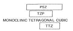
- FIG. 1shows a graph illustrating general phases of zirconia ceramics.
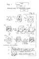
- FIG. 2shows a scheme of manufacture with the invention.
- FIG. 3shows top view of a finished ceramic body of the invention, embodied as a posterior stabilized femoral knee implant component.
- FIG. 4shows a medial to lateral side view of the component of FIG. 3 .
- FIG. 5shows a front view of the component of FIG. 3 .
- FIG. 6shows a rear view of the component of FIG. 3 .
- FIG. 7is a sectional view of the component of FIG. 3 , taken along 7 S- 7 S of FIG. 3 .
- FIG. 8is a rear, top perspective view of the component of FIG. 3 .
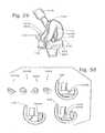
- FIGS. 9-15show some other finished ceramic bodies hereof, embodied as follows:
- FIG. 9A modular ceramic knee implant with a metal intramedular femoral post and metal securing washer, with a metal screw fastener, also with a metal or ceramic peg for a posterior stabilizing stop, shown from one side in partial section.
- FIGS. 10-11A one-piece unicompartmental knee joint spacer as a plan view ( FIG. 10 ) and side view ( FIG. 11 ).
- FIGS. 12-14A two-piece unicompartmental knee joint aligning device, shown as a side sectional view ( FIG. 12 ); a side sectional view ( FIG. 13 ) taken perpendicularly to the view of FIG. 12 , and a top view ( FIG. 14 ) in a sliding engagement mode.
- FIG. 15A temporal mandibular joint implant cap.
- FIGS. 16-19show other finished ceramic bodies, embodied as industrial apparatus, components, or devices, as follows:
- FIG. 16An industrial bearing, shown in perspective.
- FIG. 17Flow control apparatus, shown in plan.
- FIG. 18A set of gears, shown in elevation.
- FIG. 19A set of pulleys, shown in elevation.
- FIG. 20shows a scheme of manufacture with the invention to make another ceramic body, here a finished base component for an artificial prosthetic knee joint implant, which will contain a rotation device. Compare, FIG. 2 .
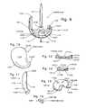
- FIG. 21is a front (anterior to posterior direction) of an artificial, prosthetic knee joint implant that may have at least a ceramic component body among its femoral and tibial components such as the base femoral component body shown in FIG. 20 , which contains a rotation device.
- FIG. 22is an exploded view of the joint of FIG. 21 .
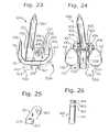
- FIG. 23is a left side view (lateral to medial direction) of the femoral component to the joint of FIGS. 21 and 22 .
- FIG. 24is a rear view (posterior to anterior direction) of the femoral component of FIG. 23 .
- FIG. 25is a left side view of the rotation device member of the femoral component in FIGS. 22-24 .
- FIG. 26is a side view of the rotation device femoral-tibial taper pin of the joint as seen in FIG. 22 .
- FIG. 27is an exploded, perspective view of a femoral component of another artificial, prosthetic knee joint of the invention containing a rotation device and having a ceramic body.
- FIG. 28is an exploded, side view of the prosthetic knee joint having the femoral component of FIG. 27 .
- FIG. 29is a front, perspective view of the joint of FIG. 28 , assembled and having several augments to accommodate bone loss in place in its femoral component.
- FIG. 30shows perspective and side views illustrating various femoral augments, some of which can be seen within FIG. 29 .
- FIG. 31is a side view of the tibial base plate found within the joint of FIG. 28 .
- FIG. 32is a top, perspective view of the tibial base plate of FIG. 31 .
- FIG. 33is a perspective view of some partial tibial augments that may be employed with the tibial base plate of FIG. 31 .
- FIG. 34is a perspective view of a ceramic provisional femoral component having a modular rotation device employed for fitting the patient to a femoral component such as that of FIG. 27 with a properly sized rotation device.
- FIG. 35is a perspective view of a ceramic provisional femoral component having snap-in augments employed for fitting the patient to a femoral component such as that of FIG. 27 with augments as may be necessary to make up for a lack of bone.
- the augment provisional componentssnap into the femoral provisional component.
- FIGS. 36-37show side views of a ceramic femoral provisional cutting guide for implantation of a femoral component such as that of FIG. 27 with drilling, as follows:
- FIG. 36In a proximal direction into resected femur.
- FIG. 37In a posterior direction into resected femur.
- FIG. 38is a saggital sectional view of a modular ceramic human knee joint of the invention.
- FIG. 39is a rear, section view of the joint of FIG. 38 .
- FIG. 40is an exploded, rear sectional view of a modular ceramic knee joint of the invention, similar to that of FIGS. 38 and 39 , employing pin type attaching of its axial (taper) pin.
- FIG. 41-43show exploded, saggital sectional views of ceramic femoral knee components with modularity, as follows:
- FIG. 41Module-in-module.
- FIG. 42Top-insert stem.
- FIG. 43One-piece box with stem, plus a rotation device added thereto.
- FIG. 44is a rear sectional view of the femoral component frame of FIGS. 41-43 .
- FIG. 45is a saggital sectional view of the insertable rotation device with a swingable, depending male type part of the modular joint of FIGS. 38 and 40 .
- FIG. 46is a rear sectional view of the insertable rotation device of FIG. 45 .
- FIG. 47is an exploded side view of another embodiment of a modular ceramic tibial tray of the invention.
- FIG. 48is an exploded rear view of the tray of FIG. 47 .
- FIG. 49is an exploded rear view of another embodiment of a modular ceramic tibial tray of the invention.
- FIGS. 50-51show views of a zirconia ceramic cruciate-retaining femoral component implant for a left human knee implant, as follows:
- FIG. 50Left, front, perspective plan view.
- FIG. 51Bottom view.
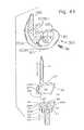
- FIG. 52is a rear, perspective view of a ceramic, unicompartmental femoral component condylar implant.
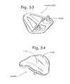
- FIGS. 53-54show views of a ceramic patellofemoral joint implant for a left human knee, as follows:
- FIG. 53Top, rear perspective.
- FIG. 54Front perspective.
- FIGS. 55-58show views of inter-spinal vertabra ensembles for implantation in adjacent, facing vertebral bodies for replacement of a disc, embodied as follows:
- FIGS. 55-56Cap or cup mounting style, shown as a side, exploded view, with one component in section ( FIG. 55 ); and a top view taken along arrow 41 A ( FIG. 56 ).
- FIGS. 57-58Peg or post mounting style, shown as a side, exploded view, with one component in section ( FIG. 57 ); and a top view taken along arrow 42 A ( FIG. 58 ).
- FIGS. 59-64show views of an ankle implant ensemble, with FIGS. 59-62 a talus cap, which may be a hemi-implant, shown in top ( FIG. 59 ); bottom ( FIG. 60 ); side ( FIG. 61 ); and front ( FIG. 62 ) views; and with FIGS. 63-64 a tibial tray, shown in side ( FIG. 63 ) and front ( FIG. 64 ) views.
- FIG. 65shows in more detail machining of an initial green body of ceramic that is held with a vacuum and/or manual chuck, said body embracing teeth.
- FIG. 66shows a ceramic ice skate blade makable hereby.
- FIGS. 67-69show views of a ceramic intermediary articulation plate for a tibial tray and liner, with FIG. 67 showing the plate; FIG. 68 a top view of the plate mounted in the tray; and FIG. 69 a sectional view of the assembled plate, tray and liner, taken along 69 - 69 in FIG. 68 .
- a ceramic bodycan be made by providing an initial green body of ceramic, and machining the initial green body to provide a machined green ceramic body.
- the machined green ceramic bodymay be fired and/or further processed to provide a more finished ceramic body.
- one or more parts to one or more components of the knee joint implantis made of ceramic.
- at least the basic femoral component with its condylar articulating surfacesis made of ceramic.
- the ceramic condylar articulating surfacesarticulate with a corresponding tibial tray liner made of ultra high molecular weight polyethylene (UHMWPE).
- UHMWPEultra high molecular weight polyethylene
- Other parts of the femoral and tibial componentsmay be made of, or to include, ceramic.
- various additional articles of manufacturemay be made. These include ceramic.
- the ceramicmay be any suitable type. Among these may be mentioned ceramics from “A” to “Z,” to include alumina to zirconia, and mixtures thereof.
- a representative ceramicmay be a boride, carbide, nitride, oxide, silicate and so forth of Al, Si, Sc, Y, La, the lanthanide series elements, Ac, the actinide series elements, Ti, Zr, Hf, V, Nb and/or Ta and so forth and the like.
- a ceramicmay be toughened; thus, for example, an alumina may be a toughened alumina as known in the art.
- the ceramicis a zirconia ceramic.
- the ceramicmay be stabilized, and any suitable stabilizer may be present in any suitable amount.
- the zirconia ceramicmay generally be a partially stabilized zirconia (PSZ) which is a zirconia ceramic stabilized, for example, with about three to three and one half percent by weight magnesium oxide, or with about from four to five percent by weight yttrium oxide, and which exists in a phase that may in essence span or be selected from tetragonal and/or cubic phases; and, from among the PSZ ceramics, a magnesium oxide stabilized transformation toughened zirconia (Mg-TTZ), which is a zirconia ceramic stabilized with approximately three to three and one half percent by weight magnesium oxide and which exists to a substantial extent in a tetragonal phase; or a yttrium oxide tetragonal zirconia polycrystalline (Y-TZP), which is a zirconia ceramic stabilized with approximately three mole percent yttrium oxide and existing to include in a tetragonal phase. Compare, FIG. 1 .
- PSZpartially stabilized zirconia
- the finished ceramicmay contain other substances.
- zirconia ceramicstypically contain a small amount of hafnia ceramic substances, say, about two percent by weight, owing to the fact that Hf is found with Zr in nature and is difficult to remove from Zr. This, however, need not be, and frequently is not, detrimental.
- the ceramicis the Mg-TTZ, especially for prosthetic implants, and those which are load bearing and/or are joint replacement parts or components, the ceramic is the Mg-TTZ, to include for reasons of its good hardness and toughness, and its excellent resistance to heat- and/or water-induced reversion toward a monoclinic phase.
- a general comparison of alumina, Y-TZP and Mg-TTZcan be made as follows:
- Y-TZP150
- Mg-TTZ125
- alumina100
- Post-autoclaveMg-TTZ (125); alumina (95); Y-TZP (50).
- Mg-TTZdoes not revert to a monoclinic phase through the in vitro action of hot water, or it is not degraded or attacked by water.
- Mg-TTZknown, for example, to have been implanted as femoral hip balls (with bores drilled after firing), should be observed to provide better short and/or long term wear than alumina and better long term wear than Y-TZP.
- the ceramic bodyinitially is made from a micropowder and/or nanopowder.
- a zirconia ceramicmay be made from monoclinic zirconia powder with an about from 0.5-micron (um) to 10-um cross-section, as a micropowder, or with an about from 1-nanometer (nm) to 500-nm cross-section, as a nanopowder, which micropowder or nanopowder may contain about from two to five percent by weight magnesium oxide as a stabilizer.
- the zirconia powderhas an about from 1-um to 2-um cross-section, as the micropowder, or an about from 15-nm to 450-nm cross-section, as the nanopowder, and contains about from 3.1 to 3.4 percent by weight magnesium oxide.
- the initial green body of ceramiccan be provided by any suitable method or process. Pressure molding is preferred to make the initial green body, especially by a cold isostatic press (CIP) technique.
- CIPcold isostatic press
- a powdered ceramic materialis fed into a cavity of a high-pressure press, and formed under pressure into the initial green body.
- a bindermay be employed if needed or desired.
- a binderis employed with the ceramic powder if it is a micropowder or larger size. It may be the case that a binder is not required for the initial green body of nanopowder.
- the initial green body of ceramicis made to have a suitable density.
- the density of the initial green bodyis at least about twenty percent of the theoretical density for that ceramic.
- the density of the initial green bodyis at least about thirty percent of theoretical, and more preferably at least about fifty percent of theoretical.
- the initial green bodymay be provided in any suitable shape.
- Convenient shapescan include cylinders, tetrahedra, triangular prisms, rectangular or cubic blocks, regular pentagonal prisms, and so forth.
- the initial green body of ceramicis provided as a rectangular or cubic block.
- certain initial green bodiesmay be left raw and pressed, and others may require heating to provide a bisque, which is considered to be a form of an initial green body.
- certain ceramic powderssuch as a zirconia nanopowder may be machined in a raw, pressed state.
- Certain other ceramic powderssuch as a micropowder for conversion into Mg-TTZ are bisqued.
- the heating required to form a bisquegenerally is considered mild.
- a zirconia micropowdermay be bisqued at temperatures about from one hundred to one thousand or eleven hundred or more degrees C., for about from one to ten hours.
- the initial green bodyis machined to provide the machined green ceramic body. Machining can be by any suitable method, to include by hand, by lathe, by drilling, cutting, and so forth, but preferably is carried out with a multi-axis precision cutting or tooling machine, for example, a computerized numerical control (CNC) machine. Generally, temperatures during the machining can be ambient temperatures.
- the machined green ceramic bodymay have any suitable shape, but preferably has a shape which is a precursor shape, analogous in most essential aspects, to the shape of any finished ceramic body.
- the present methodhas a significant advantage that the machined green body may be provided with a complex shape so that if a finished ceramic would be made from it, minimal transformation to the essential shape of the body occurs.
- asymmetrical, complex geometries as those of femoral components for a knee, to particularly include revisional femoral knee implant componentsare readily gained.
- Other complex geometries, as illustrations of the versatility of the invention, in the field of surgical implantsmay include knee joint implant tibial components, unicompartmental knee joint aligning devices of one or more pieces, ankle joint implant components, spinal components, temporal mandibular joint implants, and so forth.
- other bodiescan be made as the machined green body, including surgical implants such as hip femoral heads, shoulder humeral hemispheres, and so forth, which can advantageously include any trunnion receiving bores provided in precursor form so that the machined green body has less symmetry than an uninterrupted ball or generally planarly truncated ball (uninterrupted hemisphere), i.e., symmetry of a C-infinity point group, to include hip femoral and shoulder humeral heads with trunnion-receiving, tapered, truncated frustoconical bores, or a shape more asymmetric than C-infinity.
- complex geometries of the femoral component and/or its rotation device and/or an insertable spike, and the tibial component tray and/or an insertable spikeare readily gained.
- the machined green ceramic bodyas a precursor to a finished ceramic body, is provided suitably larger than the finished ceramic body.
- the machined green ceramic bodymay be about from one half to eighty percent larger than the corresponding finished ceramic body, in many cases about from ten to thirty percent larger.
- typical undersizes of the more finished ceramic in relation to the machined green body made from micropowderrun about from fifteen to twenty-five percent, to include about from sixteen to twenty-three percent, less than the size of the finished ceramic body.
- an eighteen percent undersized more finished ceramic based on the controlling size of the machined green bodymay be considered to be equivalent to an about one hundred twenty-two percent oversized machined green body in relation to the controlling size of the more finished ceramic body.
- a more finished ceramic body which is twenty percent undersized from a machined green bodyis made from the machined green body which is 1.25 times as large (125%) as the more finished ceramic body.
- the more finished ceramic bodyis provided. This can be accomplished through at least one heating step.
- the more finished ceramic bodycan be provided through firing of the machined green body.
- the firingmay be conducted at any suitable temperature, for instance, within ranges about from one thousand to three thousand degrees C., for any suitable time.
- a temperature gradient leading to the firing temperature in the ceramic bodyis preferred, to include as may be conducted within ranges of about from one half to twenty degrees per minute.
- Annealing of the fired piecemay immediately follow the firing, which may be carried out at any suitable temperature, for instance, within ranges about from seven hundred to one thousand eight hundred degrees C., for any suitable time.
- Further ceramic processingcan include hot isostatic press (HIP) action, as may be desired or pertinent to certain ceramics.
- HIPhot isostatic press
- a Mg-TTZ more finished ceramic bodymay be made by firing a correspondingly larger machined green body in an oven at about from one thousand six hundred to one thousand nine hundred degrees C., preferably about from one thousand seven hundred to one thousand eight hundred degrees C., for about from one to four hours, say, about from two to three hours, with ramping temperatures leading to the firing temperature increasing from room temperature to the firing temperature at a suitable rate, say, about from one to two degrees C. per minute.
- annealingis desirably carried out by gradually cooling the body from the firing temperature, keeping it in a heated condition, for example, by gradually reducing the temperature of the hot, fired body about from two hundred to five hundred degrees C., say, about three hundred fifty degrees C., below the firing temperature of the body, and holding the body at the annealing temperature for about from one to three hours, say, about two hours. Cooling from the annealing temperature may be carried out at any suitable rate, say, at a rate similar to, but the reverse of, the ramping rate, until the annealed ceramic body is about room temperature.
- Suchgenerally provides the more finished Mg-TTZ ceramic body, which typically has a density which approaches or attains theoretical density.
- no further heat processingsuch as by HIP action on the fired and annealed Mg-TTZ ceramic body is typically required.
- a Y-TZP more finished ceramic bodymay be made by firing the correspondingly larger machined green body in an oven about from one thousand three hundred to one thousand five hundred degrees C. for a body made from micropowder, or about one thousand one hundred to one thousand three hundred degrees C. for a body made from nanopowder.
- Ramping, annealing and cooling procedurescan be, in general terms, analogous to those for the Mg-TTZ ceramic. However, cooling at about from seven to ten degrees C. per minute, down to heat treating temperature, may be advantageously employed.
- HIP action under Argon or Nitrogensay, Argon
- Argonat about from one thousand to three thousand pounds per square inch (psi) pressure
- psipounds per square inch
- the finished ceramic bodymay be relieved of inorganic and organic substances, and approach or attain theoretical density.
- kiln furniturecan be employed. Such furniture is beneficially placed in non-critical parts of the body.
- the femoral knee joint implant componentmay be placed upside down in the kiln on kiln furniture that touches portions of the prosthesis that form a bone-implant interface rather than being placed right side up to have its articulating condylar surfaces touched during firing.
- the finished ceramic parts and componentscan be dense materials.
- the finished ceramicshould be at least about ninety percent of theoretical density, or it may be at least about ninety-five, ninety-six, ninety-seven, ninety-eight, or ninety-nine percent of theoretical density.
- the density of the finished ceramicapproaches, and especially attains, theoretical density.
- the more finished ceramic knee bodymay be further processed as desired or required.
- any further processingis of a minor nature, particularly when compared to what would otherwise be required to provide the final shape from machining a fired ceramic block.
- polishing and/or minor amounts of grindingare typically some of the only mechanical finishing operation(s) carried out on the more finished ceramic body.
- a tantalum-vapor deposition or a hydroxyapatite coatingmay be applied to bone-interfacing surfaces to engender ingrowth of bone.
- Various finished ceramic bodies to include those intended for implantation into human or animal subjectsare cleaned and sterilized by known methods.
- the initial green body 520 of ceramiccan be provided by any suitable method.
- itis provided by using a CIP 19 on a suitable powder 10 such as a micropowder and/or nanopowder in CIP rubber mold body 18 .
- a suitable powder 10such as a micropowder and/or nanopowder in CIP rubber mold body 18 .
- the body 520may be bisqued 521 . Sometimes it is not.
- the initial green body 520 , 521 , 521 ′can be machined without embedding it in an embedding mass to make machined green body 530 .
- a wax “handle”may be employed, in which machining wax is employed on one portion of the initial green body akin to an adhesive, without embedding it in the wax. However, even that may be avoided.
- the machiningmay be conducted with the aid of a device 600 that does not provide contact of the initial green body with an attachable substance, for example, machining wax.
- a mechanical gripsuch as a vise or chuck may be employed.
- a vacuum chuckmay be employed as the device 600 to secure an initial green body 520 / 521 and so forth for machining.
- a green ceramic body, and especially a bisqued bodymay be infiltrated or impregnated with an adjuvant, for example, heated, liquid paraffin wax, which may be carried out by simple soaking in a vessel, to provide bisqued, infiltrated body 521 ′.
- the infiltrationcan be carried out to saturation.
- the body 521 ′can be removed from the vessel and grasped with a mechanical and/or vacuum chuck, and machined. Note, steps 4 A, 4 B, 4 C of FIG. 2 .
- considerationsinclude matching surfaces of the chuck with a suitable surface of the workpiece, and the capability to provide sufficient vacuum.
- a machined green ceramic bodycan be efficiently made.
- the machined green ceramic bodymay be fired the kiln 39 having kiln furniture 38 and/or further processed to provide more finished ceramic body 540 / 550 .
- FIG. 2Note, FIG. 2 .
- ceramic prosthetic devicesheretofore unavailable in the art, to include not only a MgO-stabilized TTZ zirconia, posterior stabilized femoral component to a human knee, but also raised waffle pattern bumps for more secure mounting and engagement with resected bone. See, FIGS. 2-8 .
- other articlescan likewise be made readily and reliably, for example, prosthetic and non-prosthetic items such as those depicted in FIGS. 9-69 .
- the finished ceramicscan be strong, tough materials.
- the finished ceramicpreferably embraces a surgical implant which has as a feature thereof, a smooth, articulating ceramic surface.
- the finished ceramicsmay be light-transmissive.
- certain ceramic knee implant components of the inventioncan provide for a more rapid setting of surgical cement by use of illumination, say, with blue light, through such an implant to the cement that is in contact with both the bone stock and the implant reverse.
- illuminationsay, with blue light
- cure and surgical timescan be decreased, and a more stable bone to implant interface may be provided.
- the finished ceramic knee implant parts and componentscan be made to be of sizes which are the same as or similar to those of corresponding parts and components made of metal. In certain cases, they may be made to be slightly larger as may be desired.
- the machined green ceramic body 530and hence the more finished ceramic body 540 and the finally finished ceramic body 550 can be embodied as a femoral component 100 to a posterior stabilized knee.
- the femoral component 100of one piece of ceramic, for the posterior stabilized knee can include frame 101 with side walls 102 ; top 103 T; distal condylar flange 104 , which may include recess 104 R; posterior flange 105 ; and anterior flange 106 .
- Interiorly facing bone-ingrowth enhancing and/or cement adhering surface 109such as a porous or roughened surface can face in proximal and deep directions, and can include bumps 109 B. Polymethylmethacrylate or other surgical cement can be advantageously employed. Ridges 109 R may define and reinforce the frame 101 and flanges 104 , 105 , 106 .
- On a superficial side of the anterior flange 106can be provided trochlear surface 117 , on which the natural or an artificial patella, i.e., knee cap, may generally ride.
- condylar and trochlear surfaces 110 - 117are smooth and highly polished, for example, by use of diamond grit or dust.
- Intracondylar notch 118is formed.
- posterior stop 135which contacts a corresponding member upstanding from the tibial tray liner (not illustrated) as is well known in the art.
- FIG. 9depicts a finally finished ceramic body 550 that is embodied as a modular femoral component 100 M for a knee implant, which includes one-piece ceramic frame 101 with side walls 102 ; top 103 T, which may have hole 103 TH; distal condylar flange (not illustrated); posterior flange 105 ; and anterior flange 106 .
- Femoral condylar surface 110 of generally convex geometryagain, advantageously of constant radius of curvature in the saggital plane, especially posteriorly, generally includes inferior, medial condyle 111 ; inferior, lateral condyle (not illustrated); posterior, medial condyle 113 ; posterior, lateral condyle (not illustrated); and may be considered to include anterior, medial condyle 115 ; and anterior, lateral condyle (not illustrated).
- On a superficial side of the anterior flange 106can be provided a trochlear surface, on which the natural or an artificial knee cap may generally ride. Intracondylar notch 118 is present.
- modular stabilizationcan be provided by metal or ceramic (or other suitable material) femoral bone stock insertion stem 37 , which may be affixed by employment of screw 39 and/or washer 37 W.
- metal or ceramic (or other suitable material) posterior stabilization stop rod 135may be inserted into posterior stabilization stop rod receiving hole 135 H in the frame 101 so that the rod 135 P traverses the notch 118 . Compare, FIGS. 3-8 .
- FIGS. 10 and 11depict a finally finished ceramic body 550 that is embodied as a one-piece unicompartmental knee spacer device 100 U, which includes ceramic frame body 101 ; articular surfaces 110 ; anterior cusp 140 A; and posterior cusp 140 P. Compare, U.S. Pat. No. 6,206,927.
- FIGS. 12 , 13 and 14depict a finally finished ceramic body 550 embodied as a two-piece unicompartmental joint aligning device 100 UU, which includes lower ceramic frame body 101 L, and upper ceramic frame body 101 U; lower articular surface 110 L, intermediate sliding surfaces 110 S, and upper articular surface 110 U; first, lower lobe 141 L and first, upper lobe 141 U, which may be disposed anteriorly when implanted; second, lower lobe 142 L and second, upper lobe 142 U, which may be disposed posteriorly when implanted; engaging post 143 P; and engaging post receiving trough 143 T.
- U.S. patent application Ser. Nos. 10/717,104 and 11/189,027Compare, U.S. patent application Ser. Nos. 10/717,104 and 11/189,027.
- FIG. 15shows a ceramic temporal mandibular joint implant 100 TM/ 550 with articular surface 110 TM.
- the implant 100 TMis in a form of a cup for mounting on a resected jaw.
- FIGS. 16-19show more or finally finished ceramic bodies 540 / 550 embodied as industrial components.
- FIG. 16shows ceramic journal bearing 100 J
- FIG. 17shows ceramic flow control apparatus 100 F, including control housing 100 FH, piping 100 FP, and valving 100 FV; control housing;
- FIG. 18shows set of gears 100 G; and
- FIG. 19shows pulleys 100 P.
- FIGS. 20-49show additional embodiments of finally finished ceramic bodies 550 for ginglymous joint implants.
- FIGS. 20-33include depictions of parts or components for a rotational knee joint 1000 with natural load transfer, which includes femoral component 100 and tibial component 200 ;
- FIGS. 34 , 35 , 36 and 37depict a provisional femoral component and/or a drill jig for the femoral component 100 of a knee implant such as in FIGS. 21-29 and so forth;
- FIGS. 38-49depict modular knee joint implants, which include modularity of the type that the joint or implant can be found implanted in a first configuration, and, while the joint or implant remains implanted, it can be converted to a second configuration.
- the followingis noted:
- the femoral component 100can include femoral component frame 101 which may be of a one-piece ceramic construction.
- the frame 101can include side walls 102 ; front wall 103 , which may have upper segment 103 U, lower segment 103 L, and/or hole 103 H that may be tapped to receive screw 36 ; and top 103 T, which may have hole 103 TH and may have supporting flange 103 F, which may accommodate inferiorly insertable intramedullary femoral spike 37 , which spike 37 may be part of a boxlike module 30 that includes side walls 32 , front wall 34 that may have upper portion 34 U and lower portion 34 L, and top 33 , which mate closely with the walls 102 , 103 , 103 U, 103 L and the top 103 T, and/or including hole 34 H through which the screw 36 may pass on its way to the hole 103 H, or which spike 37 , say again, made of Cr—Co alloy, may be secured with metal washer 37 W, and has screw-receiving hole 38
- the frame 101also can include distal condylar flange 104 ; posterior flange 105 , anterior flange 106 ; femoral bone stock insertion stem 107 , which may be separately addable 107 A to stem receptacle 107 R and be secured by set screw 107 S; and wall hole 108 for integral rotation device 150 .
- Femoral bone-loss augments 104 A and 105 A for use together, and 104 AS and 105 AS for separate usemay be provided, for example, of ceramic or suitable other material such as titanium or carbon fiber, which may be coated by tantalum vapor deposition.
- Interiorly facing bone-ingrowth enhancing surface 109such as a porous or roughened surface can face in proximal and deep directions, which surface 109 may also be provided a ceramic frame 101 through coating by tantalum vapor deposition techniques, as are known in the art.
- trochlear surface 117on which the natural or an artificial knee cap may generally ride.
- Intracondylar notch 118or inferiorly insertable module housing 301 for insertion of a modular rotation device 350 and/or the modular spike 30 / 37 , may be formed.
- the condylar and trochlear surfaces 110 - 117as are articular surfaces in general, smooth and highly polished.
- Condyle-backing femoral spikes 127may be provided.
- Rotation devices 150 and 350are provided.
- the rotation device 150which may be substantially ceramic but preferably in general is metal such as Co—Cr alloy, may be embraced by UHMWPE box insert 150 B, and includes rotation member 151 generally with rotation member hole 152 ; taper pin receptacle 153 , advantageously formed with a Morse-taper-accommodating cup; and punch-pin hole 154 .
- Axle 155which may be secured by axle plug 155 P, runs through the hole 152 and may run through radial bushing 156 , say, of UHMWPE, which bushing has axle hole 157 ; insert shoulder 158 , which fits snugly in the wall hole 108 ; and member-spacing shoulder 159 .
- the rotation device 150has highly polished taper pin 160 , which can include cylindrical shaft 161 ; and may include extraction groove 162 to extract the pin 160 from the receptacle 153 , say, with a prying tool during surgical implantation of the prosthesis 1000 ; extraction-restriction punch-pin locking groove 163 ; and taper lock tip 164 , which can be made with a Morse-taper to fix the pin 160 in the cup 153 .
- the pin 160When the pin 160 is so fixed, it may be set by insertion and fit of an extraction-restriction and/or rotation-restriction punch-pin 165 through hole 154 and into groove 163 .
- Threads 166may be present, preferably in conjunction with Morse-taper 164 , as an alternative for fastening the modular taper pin 160 .
- the rotation device 350is completely modular and inferiorly insertable into the insertable modular housing 301 , preferably adapted for such with its walls 102 having a Browne & Sharpe taper, say, with an about 1.5 to 2.0 degree taper 2 ⁇ , or similar housing such as provided by the boxlike module with the spike 37 , as an embodiment of the addable component 30 , which beneficially is made of Co—Cr alloy, and can include swingable, depending male type part in housing 31 with side walls 32 , preferably with a restraining Browne & Sharpe taper 32 ⁇ about 1.6 to 2.1 degrees; optional top wall 33 , which may have top hole 33 TH; and front wall 34 . Holes 52 in the side walls 52 accommodate hinge pin (axle) 55 .
- Pivot block (rotation member) 51can have hole 52 A, which continues along the direction of the holes 52 ; taper pin cup 53 , which may be smooth walled, tapered, say, with a Morse-taper, and/or provided with threads 56 ; and punch pin hole 54 .
- the taper pin 61is inserted in the cup 53 , and may be secured through punch pin 65 and/or threads 66 .
- the rotation device 350may be made with a one-piece depending male type part as by having components 51 and 61 of one, integral piece.
- a ceramic femoral knee component 100may have a strength against a posterior condyle when tested in accordance with United States Food and Drug Administration (FDA) protocol of at least about 1500 pounds (lbs.); at least about 2000 lbs., or at least about 2500 lbs. Note, FIG. 4 , test arrow 105 T, and Example 1.
- FDAUnited States Food and Drug Administration
- Provisional or trial femoral component 100 T and/or drill jig 100 DJ for the femoral component 100may be made of ceramic according to the practice of the present invention.
- Sizing components 1005 (“hinge”) and augment provisional or trial components 100 ATmay be used with the component 100 T.
- the tibial component 200can include tibial component frame 201 , which can have tibial tray 202 ; dovetail liner-insertion rails 203 ; liner-stopping ramp or rotation safety stop 204 , and, central stop 204 C, particularly if part of double-capture locking mechanism 204 X; screw holes 205 through which can be inserted bone-fastening screws 206 ; stem 207 —which may be insertable inferiorly into receiving cup 207 C that may be threaded, by provision of separate stem 207 Q that may be threaded also; or which may be insertable superiorly, even after implantation of the component frame 201 , through hole 207 H that may be threaded, by provision of the separate stem 207 Q that has a superior screwing head with superior threads—and which may have distal taper 207 T, a number of, say, three, distal ribbed grooves 208 and/or a number, say, two, underside flanges 208 F; and interiorly facing bone
- the tibial articular surface 210is of concave geometry in suitable complimentarity to the convex geometry of the condylar surface 110 , and generally includes superior, medial articular surface 211 and superior, lateral articular surface 212 on medial lobe 213 and lateral lobe 214 , respectively.
- On the underside of each lobemay be dovetail grooves 215 for sliding along any rails 203 ; lobe-spanning portion 216 ; notch 217 for locking in cooperation with the stop(s) 204 , 204 C; and inter-condylar notch 218 analogous to the notch 118 .
- Ramp 219may make for an easier installment over the stop 204 .
- Rotation device receptacle 250may be in a form of an essentially cylindrical cup 251 , which may have top shoulder recess 252 .
- Rotation device receptacle liner 260may be inserted into the receptacle 250 and its cup 251 so as to itself receive the taper pin 60 , 160 .
- the liner 260can include taper pin accommodating cup 261 ; shoulder 262 , which can fit in the recess 252 ; a number of, say, two to four, inside, axially directed grooves 263 to permit exit of entrained body fluids during extension and flexion of the implanted joint 1000 and consequent up and down motion of the taper pin 60 , 160 , which fits quite closely although movable within the liner cup 261 ; and outside axially directed fluid-escape feature 264 , say, groove, or possible hole, to permit escape of liquids and/or gasses during insertion of the liner 260 into the receptacle 250 , between which there is a close, essentially immovable-in-use fit.
- Shoulder bevel angles A 9 a and A 9 bmay be, respectively, for example, ninety degrees and one hundred eighteen degrees.
- Tibial block augmentsmay be provided, for example, as full augment 200 F or partial augment 200 P.
- RHK full tibial block augments 200 Acan only be used with RHK tibial base plates. The table, which follows, lists some augments available from Zimmer, Inc.
- the knee implant 1000has natural load transfer.
- the kneemay carry a substantial amount, say, about ninety percent or more or about ninety-five percent or more of the load through the condyles.
- FIGS. 50 and 51are depicted a zirconia ceramic, for example, Mg-TTZ ceramic, cruciate-retaining femoral component implant 100 CR/ 550 .
- Other ceramicssuch as alumina, although not as preferred, may be employed.
- the waffle bump pattern on the bone-interfacing side of the componentThis can, as with the other implants having them, provide a grip for surgical cement in addition to any rough surface on the bone-interfacing side of the component.
- the ridges on the bone-interfacing side of the componentwhich, in addition to providing for a better cement bond, also help strengthen the implant.
- the implant 100 CRincludes smooth articular condyles 110 but has no box or other structure between the lateral and medial inferior and posterior condyles. Smooth, patella-tracking articular surface 117 is present between the condyles, especially as found between the lateral and medial anterior condyles.
- FIG. 52is depicted a ceramic, for instance, a zirconia ceramic, say, Mg-TTZ ceramic, unicompartmental femoral knee component implant 100 UK/ 550 . Note as in FIGS. 2-8 and 38 the waffle bump pattern and ridges.
- the implant 100 UKalso includes a smooth articular condyle 110 .
- FIGS. 53 and 54are depicted a ceramic, for instance, a zirconia ceramic, again, for an example, Mg-TTZ ceramic, patellofemoral joint implant 100 PF/ 550 . It includes smooth articular surface 110 and smooth, patella-tracking articular surface 117 . Note the interior ridges. A rough surface can be provided on the interior surfaces as well. Posts are provided on the bone-interfacing, interior surface in the anterior inferior position for mounting in cement on resected femoral bone stock.
- a ceramicfor instance, a zirconia ceramic, again, for an example, Mg-TTZ ceramic, patellofemoral joint implant 100 PF/ 550 . It includes smooth articular surface 110 and smooth, patella-tracking articular surface 117 . Note the interior ridges. A rough surface can be provided on the interior surfaces as well. Posts are provided on the bone-interfacing, interior surface in the anterior inferior position for mounting in cement on resected femoral bone stock.
- FIGS. 55-58depict ceramic, for instance, a zirconia ceramic, vertebra cap ensembles 100 VC/ 550 for mounting between adjacent, facing vertebrae of the spine, which include smooth, spherical section articular surfaces 110 .
- Thesemay be implanted in the cervical, thoracic or lumbar regions, for example, in the thoracic region, say, between the ninth and tenth vertebrae essentially covering their vertebral bodies, in lieu of bone fusion when disc failure is presented. This may keep spinal flexibility an option with disc failure.
- the vertebra cap ensemble componentsare mounted through a cup device in the bone-interfacing surface of the cap over resected bone.
- the componentsare mounted with the assistance of posts into resected bone. Surgical cement may be employed.
- another materialsuch as a suitable metal may be employed to make these vertebra cap ensembles.
- FIGS. 59-64depict ceramic, for instance, a zirconia ceramic, for example, Mg-TTZ ceramic, ankle joint ensemble having talus cap implant 100 AJ and tibial tray implant 200 AJ (UHMWPE tray liner not illustrated).
- the talus cap 100 AJhas articular surface 110 to articulate with natural tissue in hemi-arthroplasty or with the tray liner in total joint replacement arthroplasty, and is in a form of a cup for mounting over a stump of resected bone as with the temporal mandibular joint 100 TMJ ( FIG. 15 ), the vertebra cap ensemble 100 VC ( FIGS. 55 and 56 ), and so forth and the like.
- the tibial tray implant 200 AJmay be a suitable metal or even ceramic, and includes an intramedullary spike and a cup for receiving and retaining the liner having an articulating surface.
- FIG. 65depicts ceramic teeth in a ceramic body 530 in a precursor stage. These, for example, can be kiln treated to make finished ceramic bodies, say, of Mg-TTZ.
- FIG. 66depicts ice skate components 540 / 550 , say, of Mg-TTZ.
- FIGS. 67-69depict ceramic intermediary articulation plate 202 C, say, of alumina or MG-TTZ, for a tibial tray 202 , say, of titanium alloy, and sliding liner 220 , say of UHMWPE. Employment of the plate 202 C enhances articulation of the liner 220 riding on the plate 202 C, say over articulation otherwise between metal and UHMWPE.
- the plate 202 Cmay be press fit and/or cemented into the tray 202 , which may have circumferential lip 202 L.
- Hole 202 Hmay be provided through which can go a pin such as the pin 160 of a rotational knee femoral component into a rotation device receptacle 250 , which may have a liner, say, of UHMWPE or even ceramic.
- Rotation safety stops 204 , 204 C, 204 Xmay be provided to keep the liner 220 from too far a rotation as it slides on the ceramic plate 202 C for which the liner is afforded accommodation as by provision of suitable “cut out” volumes to interact with the stops 204 , 204 C, 204 X. Compare, FIGS. 28 , 29 , 31 and 32 .
- hand and foot digit joint implantscan be provided in ceramic hereby, and among these may be mentioned those of the fingers, thumb, and toes, notably, among the latter the great toe.
- Such an implantmay have, for example, in the case of the great toe, a suitable metal tray and intramedullary spike with an attachable ceramic tray liner having an articular surface, in lieu of the all-metal construction well known in the art.
- a finished body of a Mg-TTZ posterior stabilized femoral knee joint implant componentwas begun through CIP action on an about 3-percent magnesium oxide zirconia monoclinic 1-2 um micropowder with a binder, which was bisqued to provide a right angled 31 ⁇ 2-inch ⁇ 4-inch ⁇ 4-inch block. Then CNC machining of the block provided a green machined body 121.95% of the size of the projected more finished ceramic, as a precursor to a posterior stabilized femoral knee component with standard sized condyles. The precursor was placed with its condyles up on fired Mg-TTZ kiln furniture in an oven, which was ramped at an about 1 ⁇ 2-degree C.
- the more finished ceramic knee femoral componentcan have its reverse side roughened up by grinding with a diamond bit. Its articulating surfaces can be polished with diamond dust.
- the ceramic knee implantcan be cleaned by immersion into an aqueous bath having a surfactant, with sonic agitation of the bath. Sterilization can be by radiation and/or ethylene oxide.
- a fired, finished ceramic posterior stabilized knee femoral component 100( FIGS. 2-8 ) made as above was designated as a demonstration model.
- the component 100was deliberately thrown across a room onto a hard floor to impact against a wall.
- FIGS. 2-8Fired, finished ceramic posterior stabilized knee femoral components 100 ( FIGS. 2-8 ) made as above were tested by placing them separately in a jig and then applying stress to a posterior flange 105 along the direction of test arrow 105 T ( FIG. 4 ) to correspond to the direction that the FDA would require testing of a corresponding metal component.
- a first ceramic component with an about 1.7-mm thickness for the walls/top 102 / 103did not break when an about 1000-pound force was applied, and so the component was subjected to 15-Hz fatigue stress for 200,000 cycles with a 650-pound to 550-pound and 650-pound to 750-pound cycle without breaking.
- the componentwas broken with an about 2250-pound load, failing about its box (a wall 102 and top 103 ), but not the condyle flange 105 .
- a second component with an about 1.7-mm thickness for the walls 102was broken with an about 2300-pound load, again failing about its wall 102 and top 103 box, but not the condyle flange 105 . This is generally about three times the minimum FDA value for Co—Cr.
- a wall/top 102 / 103 of about 2 ⁇ 3 mm thicknessis desired.
- a block for a machined green body of for a Y-TZP posterior stabilized femoral knee joint componentwas made through pressure upon a monoclinic nanopowder, without binder.
- the blockcan be CNC-machined to provide a machined green ceramic body, fired and annealed, and further processed with a 1200-degree C., 20,000-psi pressure HIP to provide a theoretically dense, posterior stabilized component.
- Mg-TTZ ceramic posterior stabilized knee femoral components 100were made by the method of Example 1 but with infiltration of a bisqued green body with paraffin wax as adjuvant, removing the infiltrated body, and then machining the removed, infiltrated, bisqued green body. See, e.g., FIGS. 2-8 .
Landscapes
- Health & Medical Sciences (AREA)
- Engineering & Computer Science (AREA)
- Chemical & Material Sciences (AREA)
- Ceramic Engineering (AREA)
- Transplantation (AREA)
- Veterinary Medicine (AREA)
- Public Health (AREA)
- Oral & Maxillofacial Surgery (AREA)
- General Health & Medical Sciences (AREA)
- Animal Behavior & Ethology (AREA)
- Life Sciences & Earth Sciences (AREA)
- Mechanical Engineering (AREA)
- Orthopedic Medicine & Surgery (AREA)
- Structural Engineering (AREA)
- Heart & Thoracic Surgery (AREA)
- Cardiology (AREA)
- Manufacturing & Machinery (AREA)
- Vascular Medicine (AREA)
- Biomedical Technology (AREA)
- Medicinal Chemistry (AREA)
- Epidemiology (AREA)
- Dermatology (AREA)
- Inorganic Chemistry (AREA)
- Physical Education & Sports Medicine (AREA)
- Prostheses (AREA)
Abstract
Description
Oversize %=(100%/(100%−undersize %))(100%). I.
For example, a more finished ceramic body which is twenty percent undersized from a machined green body, is made from the machined green body which is 1.25 times as large (125%) as the more finished ceramic body.
- Step 1:
Monoclinic powder 10 is added to rubberball cavity mold 18. - Step 2: The filled
mold 18 is placed inCIP press 19. - Step 3: The
press 19 is activated to provide an initial green body, for example,green block 520. - Step 4: The
green block 520 is subject to bisquing if needed to provide bisquedgreen block 521. - Step 5: The green block521 (or520 if bisquing is not carried out) is machined, say, by CNC machine, to provide machined green
ceramic body 530. - Step 6: The machined green
ceramic body 530 is placed onsuitable kiln furniture 38 inkiln 39. - Step 7: The
kiln 39 is heated to fire the precursorceramic body 530 to provide more finishedceramic body 540. - Step 8: The more finished
ceramic body 540 may be processed further, for example, by polishing an articulating or bearing surface and/or by preparing for insertion such inserts as ultra high molecular weight polyethylene (UHMWPE) bushings, liners or other inserts as may be desired, and/or by sterilization, for instance, if it is for implantation as a prosthesis, to provide finally finishedceramic body 550.
- Step 1:
| Tibial | M/L × | RHK Full | NexGen Partial | ||
| Size | AP (mm) | Augments | Augments | ||
| 1 | 58 × 41 | ||||
| 2 | 62 × 41 | ||||
| 3 | 67 × 46 | ||||
| 4 | 70 × 46 | ||||
| 5 | 74 × 50 | ||||
| 6 | 77 × 50 | ||||
Claims (21)
Priority Applications (2)
| Application Number | Priority Date | Filing Date | Title |
|---|---|---|---|
| US13/507,395US9162008B2 (en) | 2003-03-07 | 2012-06-25 | Ceramic manufactures |
| US14/545,871US9649406B2 (en) | 2003-03-07 | 2015-06-29 | Ceramic manufactures |
Applications Claiming Priority (6)
| Application Number | Priority Date | Filing Date | Title |
|---|---|---|---|
| US45270403P | 2003-03-07 | 2003-03-07 | |
| US46392203P | 2003-04-18 | 2003-04-18 | |
| PCT/US2004/006908WO2004080340A2 (en) | 2003-03-07 | 2004-03-05 | Ceramic manufactures |
| US67724005P | 2005-05-03 | 2005-05-03 | |
| US11/220,997US9259508B2 (en) | 2003-03-07 | 2005-09-07 | Ceramic manufactures |
| US13/507,395US9162008B2 (en) | 2003-03-07 | 2012-06-25 | Ceramic manufactures |
Related Parent Applications (1)
| Application Number | Title | Priority Date | Filing Date |
|---|---|---|---|
| US11/220,997DivisionUS9259508B2 (en) | 2003-03-07 | 2005-09-07 | Ceramic manufactures |
Related Child Applications (1)
| Application Number | Title | Priority Date | Filing Date |
|---|---|---|---|
| US14/545,871ContinuationUS9649406B2 (en) | 2003-03-07 | 2015-06-29 | Ceramic manufactures |
Publications (2)
| Publication Number | Publication Date |
|---|---|
| US20120292832A1 US20120292832A1 (en) | 2012-11-22 |
| US9162008B2true US9162008B2 (en) | 2015-10-20 |
Family
ID=35733405
Family Applications (5)
| Application Number | Title | Priority Date | Filing Date |
|---|---|---|---|
| US11/220,997Active2030-12-10US9259508B2 (en) | 2003-03-07 | 2005-09-07 | Ceramic manufactures |
| US13/507,395Active - Reinstated2025-11-10US9162008B2 (en) | 2003-03-07 | 2012-06-25 | Ceramic manufactures |
| US13/507,397Active2025-11-12US9833542B2 (en) | 2003-03-07 | 2012-06-25 | Ceramic manufactures |
| US13/507,396Expired - Fee RelatedUS9694102B2 (en) | 2003-03-07 | 2012-06-25 | Ceramic manufactures |
| US14/545,871Expired - Fee RelatedUS9649406B2 (en) | 2003-03-07 | 2015-06-29 | Ceramic manufactures |
Family Applications Before (1)
| Application Number | Title | Priority Date | Filing Date |
|---|---|---|---|
| US11/220,997Active2030-12-10US9259508B2 (en) | 2003-03-07 | 2005-09-07 | Ceramic manufactures |
Family Applications After (3)
| Application Number | Title | Priority Date | Filing Date |
|---|---|---|---|
| US13/507,397Active2025-11-12US9833542B2 (en) | 2003-03-07 | 2012-06-25 | Ceramic manufactures |
| US13/507,396Expired - Fee RelatedUS9694102B2 (en) | 2003-03-07 | 2012-06-25 | Ceramic manufactures |
| US14/545,871Expired - Fee RelatedUS9649406B2 (en) | 2003-03-07 | 2015-06-29 | Ceramic manufactures |
Country Status (1)
| Country | Link |
|---|---|
| US (5) | US9259508B2 (en) |
Cited By (8)
| Publication number | Priority date | Publication date | Assignee | Title |
|---|---|---|---|---|
| US9649406B2 (en) | 2003-03-07 | 2017-05-16 | Louis A. Serafin, Jr. Trust | Ceramic manufactures |
| US10245148B2 (en) | 2016-04-25 | 2019-04-02 | Howmedica Osteonics Corp. | Flexible snap-fit prosthetic component |
| US10639160B2 (en) | 2016-08-24 | 2020-05-05 | Howmedica Osteonics Corp. | Peek femoral component with segmented TI foam in-growth |
| US20200246151A1 (en)* | 2016-03-02 | 2020-08-06 | Invibio Knees Limited | Replacement knee component |
| US11065124B2 (en) | 2018-05-25 | 2021-07-20 | Howmedica Osteonics Corp. | Variable thickness femoral augments |
| US11083585B2 (en) | 2019-05-09 | 2021-08-10 | Howmedica Osteonics Corp. | Spring retained femoral augment |
| US11491013B2 (en) | 2019-07-11 | 2022-11-08 | Howmedica Osteonics Corp. | Augment and means for connecting the same to a joint prosthesis |
| US11607323B2 (en) | 2018-10-15 | 2023-03-21 | Howmedica Osteonics Corp. | Patellofemoral trial extractor |
Families Citing this family (48)
| Publication number | Priority date | Publication date | Assignee | Title |
|---|---|---|---|---|
| US10653527B1 (en)* | 2007-03-05 | 2020-05-19 | Ceramic Medical Products, L.L.C. | Ceramic with metal/alloy coating |
| WO2008109016A1 (en)* | 2007-03-05 | 2008-09-12 | Signal Medical Corporation | Metal/alloy coated ceramic |
| US8834576B1 (en)* | 2007-03-05 | 2014-09-16 | Louis A. Serafin, Jr. | Ceramic with metal/alloy coating |
| US8382846B2 (en) | 2007-08-27 | 2013-02-26 | Kent M. Samuelson | Systems and methods for providing deeper knee flexion capabilities for knee prosthesis patients |
| US9872774B2 (en)* | 2007-08-27 | 2018-01-23 | Connor E. Samuelson | Systems and methods for providing a femoral component having a modular stem |
| US9820861B2 (en) | 2007-10-09 | 2017-11-21 | Richard Charles Smith | Rail-fixing implant |
| US9486321B1 (en)* | 2007-10-09 | 2016-11-08 | Richard C. Smith | Wedge-fixing implant |
| US20100201088A1 (en)* | 2009-02-06 | 2010-08-12 | Martin Newman | Compressive coatings for ice skate blades and methods for applying the same |
| EP2272466A1 (en) | 2009-07-10 | 2011-01-12 | Medizinische Hochschule Hannover | Knee joint prosthesis and method for producing said prosthesis |
| DE102009035972B4 (en) | 2009-08-04 | 2011-11-17 | W.C. Heraeus Gmbh | Cermet-containing lead-through for a medically implantable device |
| DE102009035971B4 (en)* | 2009-08-04 | 2013-01-17 | Heraeus Precious Metals Gmbh & Co. Kg | Electrical leadthrough for a medically implantable device |
| US9918842B1 (en) | 2009-12-16 | 2018-03-20 | Signal Medical Corporation | Knee system |
| DE102010006689B4 (en)* | 2010-02-02 | 2013-04-18 | Heraeus Precious Metals Gmbh & Co. Kg | Method for producing an electrical feedthrough, electrical feedthrough and implantable device |
| DE102010006690B4 (en) | 2010-02-02 | 2013-03-28 | Heraeus Precious Metals Gmbh & Co. Kg | Method for producing an electrical feedthrough, electrical feedthrough and implantable device |
| CN102009175B (en)* | 2010-10-08 | 2013-08-21 | 李亚东 | Manufacturing method of multilayer shell-core composite structural part |
| EP3175824B1 (en) | 2011-11-18 | 2019-01-02 | Zimmer, Inc. | Tibial bearing component for a knee prosthesis with improved articular characteristics |
| US20140031949A1 (en)* | 2012-06-27 | 2014-01-30 | Signal Medical Corporation | Ceramic antibacterial |
| US9399309B2 (en)* | 2012-11-02 | 2016-07-26 | Amedica Corporation | Methods for threading sinterable materials and related apparatus and systems |
| US9478959B2 (en) | 2013-03-14 | 2016-10-25 | Heraeus Deutschland GmbH & Co. KG | Laser welding a feedthrough |
| US9431801B2 (en) | 2013-05-24 | 2016-08-30 | Heraeus Deutschland GmbH & Co. KG | Method of coupling a feedthrough assembly for an implantable medical device |
| US9403023B2 (en) | 2013-08-07 | 2016-08-02 | Heraeus Deutschland GmbH & Co. KG | Method of forming feedthrough with integrated brazeless ferrule |
| US9504841B2 (en) | 2013-12-12 | 2016-11-29 | Heraeus Deutschland GmbH & Co. KG | Direct integration of feedthrough to implantable medical device housing with ultrasonic welding |
| US9610452B2 (en) | 2013-12-12 | 2017-04-04 | Heraeus Deutschland GmbH & Co. KG | Direct integration of feedthrough to implantable medical device housing by sintering |
| US9610451B2 (en) | 2013-12-12 | 2017-04-04 | Heraeus Deutschland GmbH & Co. KG | Direct integration of feedthrough to implantable medical device housing using a gold alloy |
| US10548735B2 (en) | 2015-08-06 | 2020-02-04 | Howmedica Osteonics Corp. | Modular hinge knee prosthesis and improvements of same |
| EP3238655A1 (en)* | 2016-04-28 | 2017-11-01 | 3M Innovative Properties Company | A method of making a dental restoration |
| US10722372B2 (en) | 2016-07-05 | 2020-07-28 | Howmedica Osteonics Corp. | Hinge knee preparation instrumentation and associated methods |
| JP6893556B2 (en)* | 2016-12-23 | 2021-06-23 | イフォクレール ヴィヴァデント アクチェンゲゼルシャフトIvoclar Vivadent AG | Multilayer oxide ceramic body with suitable sintering behavior |
| EP3592283B1 (en) | 2017-03-10 | 2024-05-08 | Alps Holding Llc | Hard-tissue implant comprising a bulk implant, a face, pillars, slots, and at least one support member |
| US11324606B2 (en) | 2017-03-10 | 2022-05-10 | Gary A. Zwick | Spinal interbody cage comprising a bulk interbody cage, a top face, a bottom face, pillars, and slots |
| US10849759B2 (en)* | 2017-03-13 | 2020-12-01 | Floyd G. Goodman | Ceramic multi-hooded enarthrodial joint implant |
| US11583405B2 (en) | 2017-03-13 | 2023-02-21 | Floyd G. Goodman | Hard substance multi-hooded enarthrodial joint implant |
| US10524921B2 (en) | 2017-03-14 | 2020-01-07 | Floyd G. Goodman | Universal joint implant for shoulder |
| WO2018208612A1 (en)* | 2017-05-12 | 2018-11-15 | Zimmer, Inc. | Femoral prostheses with upsizing and downsizing capabilities |
| US11278427B2 (en) | 2018-04-10 | 2022-03-22 | Gary A. Zick, Trustee Of The Everest Trust Uta April 20, 2017 | Spinal interbody cage comprising top and bottom faces with mesh structures, pillars and slots |
| US11819806B1 (en) | 2018-10-15 | 2023-11-21 | Ampcera Inc. | Methods for manufacturing a solid state ionic conductive membrane on a macro porous support scaffold |
| US12154702B1 (en) | 2018-10-15 | 2024-11-26 | Ampcera Inc. | Methods for manufacturing a freestanding solid state ionic conductive membrane |
| US11177498B1 (en) | 2018-10-15 | 2021-11-16 | Ampcera Inc. | Redox flow batteries, components for redox flow batteries and methods for manufacture thereof |
| IT201800009555A1 (en)* | 2018-10-18 | 2020-04-18 | Tecres Spa | INTERMEDIATE DEVICE OR SUB-TIBIAL INSERT, PROSTHETIC COMPONENT EQUIPPED WITH THIS INTERMEDIATE DEVICE AND METHOD FOR THEIR ASSEMBLY |
| US11600853B1 (en) | 2019-05-14 | 2023-03-07 | Ampcera Inc. | Systems and methods for storing, transporting, and handling of solid-state electrolytes |
| US11596519B2 (en) | 2019-07-16 | 2023-03-07 | Howmedica Osteonics Corp. | Hinge knee assembly guide |
| JP2021029831A (en)* | 2019-08-28 | 2021-03-01 | 京セラ株式会社 | Biological zirconia ceramic member and its manufacturing method |
| JP7335428B2 (en) | 2019-09-11 | 2023-08-29 | アルプス ホールディング エルエルシー | An implant comprising a first set and a second set of pillars for attaching a tendon or ligament to hard tissue |
| CN110755681B (en)* | 2019-10-31 | 2023-09-08 | 吉瑞骨科有限公司 | Metal and ceramic composite joint prosthesis and manufacturing method thereof |
| EP4226968B1 (en) | 2020-02-21 | 2025-04-30 | Heraeus Medical Components, LLC | Ferrule for non-planar medical device housing |
| EP3900782B1 (en) | 2020-02-21 | 2023-08-09 | Heraeus Medical Components, LLC | Ferrule with strain relief spacer for implantable medical device |
| US12257689B1 (en) | 2021-01-22 | 2025-03-25 | Gerard M. Verellen | Tool bit caddy |
| CN114569799B (en)* | 2022-03-24 | 2023-01-06 | 卢霄 | Metal prosthesis bearing modular ceramics and preparation method thereof |
Citations (105)
| Publication number | Priority date | Publication date | Assignee | Title |
|---|---|---|---|---|
| US3314420A (en) | 1961-10-23 | 1967-04-18 | Haeger Potteries Inc | Prosthetic parts and methods of making the same |
| US4067745A (en) | 1974-10-24 | 1978-01-10 | Commonwealth Scientific And Industrial Research Organization | Ceramic materials |
| US4081866A (en) | 1977-02-02 | 1978-04-04 | Howmedica, Inc. | Total anatomical knee prosthesis |
| JPS55121970A (en) | 1979-01-04 | 1980-09-19 | Commw Scient Ind Res Org | Partially stabilized zirconia ceramic |
| US4279655A (en) | 1979-01-04 | 1981-07-21 | Garvie Ronald C | Partially stabilized zirconia ceramics |
| CA1154793A (en) | 1980-03-26 | 1983-10-04 | Syunzo Mase | Zirconia ceramics and a method of producing the same |
| EP0135919A2 (en) | 1983-09-21 | 1985-04-03 | Eduard Winner | Method of and apparatus for mixing granular components |
| US4634561A (en) | 1985-03-22 | 1987-01-06 | Johnson & Johnson Dental Products Company | Method for joining ceramic components in precise spatial relationship |
| WO1987002658A1 (en) | 1985-10-29 | 1987-05-07 | The Dow Chemical Company | Sinterable and strengthened magnesium oxide ceramic materials |
| US4665040A (en) | 1982-01-12 | 1987-05-12 | Kureha Chemical Industry Co., Ltd. | Alumina-zirconia ceramic powders and a method of making the same |
| EP0303467A2 (en) | 1987-08-10 | 1989-02-15 | Dow Corning Wright Corporation | Prosthesis for femoral component of knee joint |
| US4840630A (en) | 1986-06-05 | 1989-06-20 | Kyocera Corporation | Artificial hip joint |
| US4885266A (en) | 1982-06-01 | 1989-12-05 | Commonwealth Scientific And Industrial Research Organization | Zirconia ceramic materials and method for making same |
| US4888311A (en) | 1986-10-14 | 1989-12-19 | Nicolas Davidovits | Ceramic-ceramic composite material and production method |
| JPH0221857A (en) | 1988-02-19 | 1990-01-24 | Michael Sadoun | Dental straightener and manufacture thereof |
| JPH0274562A (en) | 1988-09-07 | 1990-03-14 | Namiki Precision Jewel Co Ltd | Method for processing partially stabilized zirconia |
| EP0360773A2 (en) | 1988-09-19 | 1990-03-28 | Corning Incorporated | Transformation toughened ceramic alloys |
| US4939996A (en) | 1986-09-03 | 1990-07-10 | Coors Porcelain Company | Ceramic munitions projectile |
| US4957509A (en) | 1986-02-28 | 1990-09-18 | Agency Of Industrial Science And Technology | Ceramic implant materials |
| EP0389461A1 (en) | 1989-03-23 | 1990-09-26 | Sandvik Aktiebolag | Artificial onlay tooth crowns and inlays |
| US4977114A (en)* | 1986-11-28 | 1990-12-11 | Sumitomo Chemical Company, Limited | Zirconia ceramics and method for producing same |
| US5037438A (en) | 1989-07-25 | 1991-08-06 | Richards Medical Company | Zirconium oxide coated prosthesis for wear and corrosion resistance |
| JPH03267055A (en) | 1990-03-16 | 1991-11-27 | Koshino Nariko | Shank side component of artificial knee joint |
| US5082809A (en)* | 1987-12-21 | 1992-01-21 | Kyocera Corporation | High-strength alumina sintered body and process for preparation thereof |
| US5099052A (en) | 1990-04-13 | 1992-03-24 | Washington Research Foundation | Silicon and aluminum complexes |
| EP0477157A1 (en) | 1990-09-17 | 1992-03-25 | Sandvik Aktiebolag | Artificial tooth veneer restorations |
| US5112433A (en) | 1988-12-09 | 1992-05-12 | Battelle Memorial Institute | Process for producing sub-micron ceramic powders of perovskite compounds with controlled stoichiometry and particle size |
| US5116376A (en) | 1988-10-18 | 1992-05-26 | University College London | Knee prosthesis |
| US5135154A (en) | 1989-11-13 | 1992-08-04 | Okabe Co., Ltd. | Reusable stud welding ferrule containing boron nitride |
| US5139521A (en) | 1990-01-27 | 1992-08-18 | Ingrid Schelhas | Knee prosthesis |
| WO1992020634A2 (en) | 1991-05-16 | 1992-11-26 | Coors Ceramicon Designs, Ltd. | Method of coating ceramic material and ceramic material produced thereby |
| US5175132A (en) | 1991-11-19 | 1992-12-29 | Ketcham Thomas D | Sinterable ceramic compositions |
| US5192472A (en) | 1989-02-23 | 1993-03-09 | Nobelpharma Ab | Method for producing a ceramic article |
| US5238742A (en) | 1990-01-16 | 1993-08-24 | Dow Corning Corporation | Polymer derived ceramic fibers having improved thermal stability |
| JPH05269720A (en) | 1992-03-26 | 1993-10-19 | Ngk Insulators Ltd | Molding tool of ceramic valve and molding method of ceramic valve for which that molding tool is used |
| EP0580565A2 (en) | 1992-06-23 | 1994-01-26 | Sandvik Aktiebolag | Method of manufacturing ceramic artificial tooth restorations |
| US5287698A (en) | 1989-12-27 | 1994-02-22 | Nissan Motor Co., Ltd. | Exhaust gas purifying device for an internal combustion engine |
| US5290332A (en) | 1992-03-05 | 1994-03-01 | Eastman Kodak Company | Ceramic articles and methods for preparing ceramic articles and for sintering |
| US5336282A (en) | 1991-12-31 | 1994-08-09 | Eastman Kodak Company | Zirconia ceramics and a process of producing the same |
| US5358529A (en) | 1993-03-05 | 1994-10-25 | Smith & Nephew Richards Inc. | Plastic knee femoral implants |
| US5358910A (en) | 1993-05-04 | 1994-10-25 | Dow Corning Corporation | Porous silicon carbide ceramics using filled polysiloxanes |
| JPH06351209A (en) | 1993-06-08 | 1994-12-22 | Ibiden Co Ltd | Brushless motor |
| EP0634149A1 (en) | 1993-06-24 | 1995-01-18 | Metoxit Ag | Process for manufacturing prostheses |
| US5418298A (en) | 1993-03-19 | 1995-05-23 | Regents Of The University Of Michigan | Neutral and mixed neutral/anionic polymetallooxanes |
| US5453262A (en) | 1988-12-09 | 1995-09-26 | Battelle Memorial Institute | Continuous process for production of ceramic powders with controlled morphology |
| US5485641A (en) | 1993-10-18 | 1996-01-23 | Snap-On Incorporated | Composite/plier cutter tool with shear action cutter insert |
| DE4434806A1 (en) | 1994-09-29 | 1996-04-04 | Peter Brehm | Prosthesis for knee joints |
| EP0716839A1 (en) | 1994-12-12 | 1996-06-19 | Biomedical Engineering Trust I | Hinged knee prothesis with condylar bearing |
| EP0724868A1 (en) | 1995-01-31 | 1996-08-07 | SULZER Medizinaltechnik AG | Joint prothesis, in particular a knee prosthesis |
| US5549684A (en) | 1989-12-26 | 1996-08-27 | Kyocera Corporation | Artificial knee joint |
| US5565152A (en) | 1989-03-23 | 1996-10-15 | Sandvik Ab | Method of making artificial tooth veneer |
| US5593719A (en) | 1994-03-29 | 1997-01-14 | Southwest Research Institute | Treatments to reduce frictional wear between components made of ultra-high molecular weight polyethylene and metal alloys |
| WO1997030663A1 (en) | 1996-02-26 | 1997-08-28 | Krakovits Gabor | Knee surface replacement prosthesis |
| US5730928A (en) | 1996-08-23 | 1998-03-24 | Eastman Kodak Company | Method of making air lubricated hydrodynamic ceramic bearings |
| US5766257A (en) | 1997-01-28 | 1998-06-16 | Implant Manufacturing And Testing Corporation | Artificial joint having natural load transfer |
| WO1998052499A1 (en) | 1997-05-21 | 1998-11-26 | Smith & Nephew, Inc. | Trial femoral prosthesis for use in knee joint replacement surgery |
| US5849068A (en)* | 1993-06-24 | 1998-12-15 | Dentsply G.M.B.H. | Dental prosthesis |
| US5873725A (en) | 1996-11-12 | 1999-02-23 | Perler; Robert | Support post and method for coronal prosthesis |
| US5919493A (en) | 1992-10-13 | 1999-07-06 | Ushers, Inc. | Apparatus for producing shaped articles |
| US5922161A (en) | 1995-06-30 | 1999-07-13 | Commonwealth Scientific And Industrial Research Organisation | Surface treatment of polymers |
| US5939147A (en) | 1996-10-31 | 1999-08-17 | The United States Of America As Represented By The Secretary Of The Navy | Scandia, yttria-stabilized zirconia for ultra-high temperature thermal barrier coatings |
| JPH11228221A (en) | 1998-02-09 | 1999-08-24 | Matsushita Electric Works Ltd | Zirconia-based composite ceramic sintered compact for biological use |
| US5958361A (en) | 1993-03-19 | 1999-09-28 | Regents Of The University Of Michigan | Ultrafine metal oxide powders by flame spray pyrolysis |
| US5962007A (en) | 1997-12-19 | 1999-10-05 | Indigo Medical, Inc. | Use of a multi-component coil medical construct |
| US5964745A (en) | 1993-07-02 | 1999-10-12 | Med Usa | Implantable system for cell growth control |
| GB2336317A (en) | 1996-12-09 | 1999-10-20 | Jacques Afriat | Complete knee joint prosthesis |
| JPH11318961A (en) | 1998-04-15 | 1999-11-24 | Aesculap | Artificial knee |
| US6017839A (en) | 1998-02-09 | 2000-01-25 | Eastman Kodak Company | Ceramic article |
| US6033222A (en) | 1997-04-25 | 2000-03-07 | Schneider, Ii; George J. | Method of fabrication of translucent dental restorations without opacious substructures |
| US6106747A (en) | 1995-03-28 | 2000-08-22 | Wohlwend; Arnold | Process for manufacturing prostetic dental reconstructions |
| DE19930564A1 (en) | 1999-04-16 | 2000-10-19 | Kaltenbach & Voigt | Ceramic molding, especially medical or dental prosthesis or implant, is produced by machining pressed green ceramic body to desired inner and-or outer contour prior to sintering |
| US6147135A (en) | 1998-12-31 | 2000-11-14 | Ethicon, Inc. | Fabrication of biocompatible polymeric composites |
| US6149073A (en) | 1994-05-18 | 2000-11-21 | Cummins Engine Company, Inc. | Ceramic plunger for internal combustion engine high pressure fuel system |
| US6206927B1 (en) | 1999-04-02 | 2001-03-27 | Barry M. Fell | Surgically implantable knee prothesis |
| US6235225B1 (en) | 1999-08-10 | 2001-05-22 | Ngk Spark Plug Co., Ltd. | Process for producing biocompatible implant material |
| US6302913B1 (en) | 1994-05-24 | 2001-10-16 | Implico B.V. | Biomaterial and bone implant for bone repair and replacement |
| WO2001080917A2 (en) | 2000-04-27 | 2001-11-01 | Saint-Gobain Ceramiques Avancees Desmarquest | Yttrium-doped zirconia biomedical component |
| US6322050B2 (en) | 2000-04-19 | 2001-11-27 | Flowserve Corporation | Method of manufacture of element having ceramic insert and high-strength element-to-shaft connection for use in a valve |
| US20020006532A1 (en) | 2000-04-26 | 2002-01-17 | Arnaud Robin | Bonded LTD-resistant zirconia dental components |
| US20020010512A1 (en) | 2000-07-19 | 2002-01-24 | Tsunenori Takei | Artificial knee joint |
| JP2002047483A (en) | 2000-08-04 | 2002-02-12 | Fujimi Inc | Polishing composition and polishing method using the same |
| US6380113B1 (en) | 1999-05-07 | 2002-04-30 | Korea Institute Of Science & Technology | Tetragonal zirconia ceramic powders, tetragonal zirconia-alumina composite using the ceramic powder and method of preparation for the same |
| US6451059B1 (en) | 1999-11-12 | 2002-09-17 | Ethicon, Inc. | Viscous suspension spinning process for producing resorbable ceramic fibers and scaffolds |
| US6495073B2 (en) | 1999-04-16 | 2002-12-17 | Kaltenbach & Voigt Gmbh & Co. | Method for the manufacture of medical, dental-medical, dental-technical and technical parts from ceramics |
| US6524345B1 (en) | 1996-10-25 | 2003-02-25 | Bionx Implants Oy | Surgical implant |
| JP2003061991A (en) | 2001-08-30 | 2003-03-04 | Kyocera Corp | Artificial knee joint |
| US6558794B1 (en) | 2000-06-26 | 2003-05-06 | Technology Assessment & Transfer, Inc. | Ceramic particulate reinforced orthopedic implants |
| US20030143350A1 (en) | 2002-01-14 | 2003-07-31 | Oscar Jimenez | Angioplasty super balloon fabrication with composite materials |
| US20030153984A1 (en) | 2001-06-14 | 2003-08-14 | Amedica Corporation | Metal-ceramic composite articulation |
| US6629999B1 (en) | 1999-03-08 | 2003-10-07 | Louis A. Serafin, Jr. | Modular joint |
| US6634059B2 (en) | 2000-08-17 | 2003-10-21 | Innovative Product Solutions, Inc. | Reinforcement hardware for a doorjamb bracket |
| US20030235738A1 (en)* | 2002-06-19 | 2003-12-25 | Yongjian Zheng | Monolithic fuel cell and method of manufacture of same |
| US20040039450A1 (en) | 2002-08-26 | 2004-02-26 | Griner Adam M. | Easily assembled provisional orthopaedic implant |
| WO2004080340A2 (en) | 2003-03-07 | 2004-09-23 | Serafin Louis A Jr | Ceramic manufactures |
| US20050149102A1 (en) | 2003-12-22 | 2005-07-07 | Radisch Herbert R.Jr. | Medical device systems |
| US6955716B2 (en) | 2002-03-01 | 2005-10-18 | American Dental Association Foundation | Self-hardening calcium phosphate materials with high resistance to fracture, controlled strength histories and tailored macropore formation rates |
| US20060015136A1 (en) | 2002-09-19 | 2006-01-19 | Memory Metal Holland Bv | Vascular filter with improved strength and flexibility |
| US20060025866A1 (en)* | 2003-03-07 | 2006-02-02 | Serafin Louis A Jr | Ceramic manufactures |
| US7250381B2 (en) | 2004-11-12 | 2007-07-31 | Johns Manville | Fibrous nonwoven mats containing polyethermid fibers |
| US20070179041A1 (en) | 2004-09-01 | 2007-08-02 | Advanced Nanotechnology Limited | Zirconia Ceramic |
| US20070255392A1 (en) | 2006-04-27 | 2007-11-01 | Phillips Plastics Corporation | Composite stent |
| US20100007240A1 (en) | 2004-03-12 | 2010-01-14 | Sri International | Mechanical meta-materials |
| US20100055336A1 (en) | 2005-08-26 | 2010-03-04 | Sanjay Patel | Method of making polymer particles mixed with fibers, and products such as press fabrics made therefrom |
| US20140031949A1 (en)* | 2012-06-27 | 2014-01-30 | Signal Medical Corporation | Ceramic antibacterial |
| US20150053898A1 (en)* | 2013-08-23 | 2015-02-26 | Agc Seimi Chemical Co., Ltd. | Composite oxide powder for solid oxide fuel cell and its production method |
Family Cites Families (19)
| Publication number | Priority date | Publication date | Assignee | Title |
|---|---|---|---|---|
| US6789191B1 (en)* | 1999-05-25 | 2004-09-07 | Silverbrook Research Pty Ltd | Interactive device network registration protocol |
| US3634113A (en)* | 1968-10-30 | 1972-01-11 | Larry L Fehrenbacher | Stabilized zirconium dioxide and hafnium dioxide compositions |
| FR2445913A1 (en) | 1979-01-04 | 1980-08-01 | Le Mans Constructeur Car Bus | DEVICE FOR CONTROLLING AN AUTOMATIC TRANSMISSION OF A MOTOR VEHICLE |
| JPS5741942A (en) | 1980-08-27 | 1982-03-09 | Tokan Kogyo Co Ltd | Manufacture of paper vessel |
| JPS62153163A (en) | 1985-09-06 | 1987-07-08 | 東レ株式会社 | Zirconia sintered body |
| US5024976A (en)* | 1988-11-03 | 1991-06-18 | Kennametal Inc. | Alumina-zirconia-silicon carbide-magnesia ceramic cutting tools |
| US6517583B1 (en)* | 2000-01-30 | 2003-02-11 | Diamicron, Inc. | Prosthetic hip joint having a polycrystalline diamond compact articulation surface and a counter bearing surface |
| GB2305430B (en)* | 1995-09-21 | 1997-08-27 | Matsushita Electric Works Ltd | Zirconia based ceramic material and process of making the same |
| US5837432A (en)* | 1996-06-27 | 1998-11-17 | Eastman Kodak Company | Photographic reversal process prebleach concentrate and method of use |
| US5738446A (en) | 1996-08-23 | 1998-04-14 | Eastman Kodak Company | Air lubricated hydrodynamic ceramic bearings |
| JP2945935B2 (en)* | 1996-10-01 | 1999-09-06 | 松下電工株式会社 | Zirconia-based composite ceramic sintered body and method for producing the same |
| US6008432A (en)* | 1997-10-01 | 1999-12-28 | Osteonics Corp. | Metallic texture coated prosthetic implants |
| US6723672B1 (en)* | 1999-01-26 | 2004-04-20 | Carpenter Advanced Ceramics, Inc. | High-strength magnesia partially stabilized zirconia |
| ATE246523T1 (en) | 1999-11-02 | 2003-08-15 | Matsushita Electric Works Ltd | REPAIR MATERIAL FOR HARD TISSUE |
| US20020010070A1 (en)* | 2000-04-25 | 2002-01-24 | Bernard Cales | Zirconia-toughened alumina biocomponent having high resistance to low temperature degradation and method for preparing same |
| US6806391B2 (en)* | 2002-07-31 | 2004-10-19 | Shell Oil Company | Process for the carbonylation of ethylenically unsaturated compounds and bidentate diphosphine composition used in this process |
| JP2010501450A (en)* | 2006-08-18 | 2010-01-21 | ペントロン・セラミックス・インコーポレイテッド | Coloring ceramics by controlling the atmosphere |
| US8043382B2 (en)* | 2007-02-28 | 2011-10-25 | Biomet Manufacturing Corp. | Reinforced medical implants |
| WO2008109016A1 (en)* | 2007-03-05 | 2008-09-12 | Signal Medical Corporation | Metal/alloy coated ceramic |
- 2005
- 2005-09-07USUS11/220,997patent/US9259508B2/enactiveActive
- 2012
- 2012-06-25USUS13/507,395patent/US9162008B2/enactiveActive - Reinstated
- 2012-06-25USUS13/507,397patent/US9833542B2/enactiveActive
- 2012-06-25USUS13/507,396patent/US9694102B2/ennot_activeExpired - Fee Related
- 2015
- 2015-06-29USUS14/545,871patent/US9649406B2/ennot_activeExpired - Fee Related
Patent Citations (127)
| Publication number | Priority date | Publication date | Assignee | Title |
|---|---|---|---|---|
| US3314420A (en) | 1961-10-23 | 1967-04-18 | Haeger Potteries Inc | Prosthetic parts and methods of making the same |
| US4067745A (en) | 1974-10-24 | 1978-01-10 | Commonwealth Scientific And Industrial Research Organization | Ceramic materials |
| US4081866A (en) | 1977-02-02 | 1978-04-04 | Howmedica, Inc. | Total anatomical knee prosthesis |
| JPS5741942B2 (en) | 1977-02-02 | 1982-09-06 | ||
| JPS55121970A (en) | 1979-01-04 | 1980-09-19 | Commw Scient Ind Res Org | Partially stabilized zirconia ceramic |
| US4279655A (en) | 1979-01-04 | 1981-07-21 | Garvie Ronald C | Partially stabilized zirconia ceramics |
| CA1154793A (en) | 1980-03-26 | 1983-10-04 | Syunzo Mase | Zirconia ceramics and a method of producing the same |
| US4665040A (en) | 1982-01-12 | 1987-05-12 | Kureha Chemical Industry Co., Ltd. | Alumina-zirconia ceramic powders and a method of making the same |
| US4885266A (en) | 1982-06-01 | 1989-12-05 | Commonwealth Scientific And Industrial Research Organization | Zirconia ceramic materials and method for making same |
| EP0135919A2 (en) | 1983-09-21 | 1985-04-03 | Eduard Winner | Method of and apparatus for mixing granular components |
| US4678761A (en) | 1984-10-29 | 1987-07-07 | The Dow Chemical Company | Sinterable and strengthened magnesium oxide ceramic materials |
| US4634561A (en) | 1985-03-22 | 1987-01-06 | Johnson & Johnson Dental Products Company | Method for joining ceramic components in precise spatial relationship |
| WO1987002658A1 (en) | 1985-10-29 | 1987-05-07 | The Dow Chemical Company | Sinterable and strengthened magnesium oxide ceramic materials |
| US4957509A (en) | 1986-02-28 | 1990-09-18 | Agency Of Industrial Science And Technology | Ceramic implant materials |
| US4840630A (en) | 1986-06-05 | 1989-06-20 | Kyocera Corporation | Artificial hip joint |
| US4939996A (en) | 1986-09-03 | 1990-07-10 | Coors Porcelain Company | Ceramic munitions projectile |
| US4888311A (en) | 1986-10-14 | 1989-12-19 | Nicolas Davidovits | Ceramic-ceramic composite material and production method |
| US4977114A (en)* | 1986-11-28 | 1990-12-11 | Sumitomo Chemical Company, Limited | Zirconia ceramics and method for producing same |
| EP0303467A2 (en) | 1987-08-10 | 1989-02-15 | Dow Corning Wright Corporation | Prosthesis for femoral component of knee joint |
| US5082809A (en)* | 1987-12-21 | 1992-01-21 | Kyocera Corporation | High-strength alumina sintered body and process for preparation thereof |
| JPH0221857A (en) | 1988-02-19 | 1990-01-24 | Michael Sadoun | Dental straightener and manufacture thereof |
| US5011403A (en) | 1988-02-19 | 1991-04-30 | Michael Sadoun | Orthodontic bracket made from zirconium oxide |
| US5011403B1 (en) | 1988-02-19 | 1995-10-31 | Michael Sadoun | Orthodontic bracket made from zirconium oxide |
| JPH0274562A (en) | 1988-09-07 | 1990-03-14 | Namiki Precision Jewel Co Ltd | Method for processing partially stabilized zirconia |
| US4939107A (en) | 1988-09-19 | 1990-07-03 | Corning Incorporated | Transformation toughened ceramic alloys |
| EP0360773A2 (en) | 1988-09-19 | 1990-03-28 | Corning Incorporated | Transformation toughened ceramic alloys |
| US5116376A (en) | 1988-10-18 | 1992-05-26 | University College London | Knee prosthesis |
| US5112433A (en) | 1988-12-09 | 1992-05-12 | Battelle Memorial Institute | Process for producing sub-micron ceramic powders of perovskite compounds with controlled stoichiometry and particle size |
| US5453262A (en) | 1988-12-09 | 1995-09-26 | Battelle Memorial Institute | Continuous process for production of ceramic powders with controlled morphology |
| US5192472A (en) | 1989-02-23 | 1993-03-09 | Nobelpharma Ab | Method for producing a ceramic article |
| US5565152A (en) | 1989-03-23 | 1996-10-15 | Sandvik Ab | Method of making artificial tooth veneer |
| US5106303A (en) | 1989-03-23 | 1992-04-21 | Sandvik Ab | Methods of making artificial tooth onlays and inlays |
| EP0389461A1 (en) | 1989-03-23 | 1990-09-26 | Sandvik Aktiebolag | Artificial onlay tooth crowns and inlays |
| US5037438A (en) | 1989-07-25 | 1991-08-06 | Richards Medical Company | Zirconium oxide coated prosthesis for wear and corrosion resistance |
| US5135154A (en) | 1989-11-13 | 1992-08-04 | Okabe Co., Ltd. | Reusable stud welding ferrule containing boron nitride |
| US5549684A (en) | 1989-12-26 | 1996-08-27 | Kyocera Corporation | Artificial knee joint |
| US5287698A (en) | 1989-12-27 | 1994-02-22 | Nissan Motor Co., Ltd. | Exhaust gas purifying device for an internal combustion engine |
| US5238742A (en) | 1990-01-16 | 1993-08-24 | Dow Corning Corporation | Polymer derived ceramic fibers having improved thermal stability |
| US5139521A (en) | 1990-01-27 | 1992-08-18 | Ingrid Schelhas | Knee prosthesis |
| US5137536A (en) | 1990-03-16 | 1992-08-11 | Nariko Koshino | Tibial component for artificial knee joint |
| JPH03267055A (en) | 1990-03-16 | 1991-11-27 | Koshino Nariko | Shank side component of artificial knee joint |
| US5099052A (en) | 1990-04-13 | 1992-03-24 | Washington Research Foundation | Silicon and aluminum complexes |
| EP0477157A1 (en) | 1990-09-17 | 1992-03-25 | Sandvik Aktiebolag | Artificial tooth veneer restorations |
| WO1992020634A2 (en) | 1991-05-16 | 1992-11-26 | Coors Ceramicon Designs, Ltd. | Method of coating ceramic material and ceramic material produced thereby |
| US5175132A (en) | 1991-11-19 | 1992-12-29 | Ketcham Thomas D | Sinterable ceramic compositions |
| US5336282A (en) | 1991-12-31 | 1994-08-09 | Eastman Kodak Company | Zirconia ceramics and a process of producing the same |
| US5411690A (en) | 1991-12-31 | 1995-05-02 | Eastman Kodak Company | Process for producing a tetragonal phase zirconia ceramic |
| US5290332A (en) | 1992-03-05 | 1994-03-01 | Eastman Kodak Company | Ceramic articles and methods for preparing ceramic articles and for sintering |
| US5358913A (en) | 1992-03-05 | 1994-10-25 | Eastman Kodak Company | Zirconia ceramic articles having a tetragonal core and cubic casing |
| JPH05269720A (en) | 1992-03-26 | 1993-10-19 | Ngk Insulators Ltd | Molding tool of ceramic valve and molding method of ceramic valve for which that molding tool is used |
| EP0580565A2 (en) | 1992-06-23 | 1994-01-26 | Sandvik Aktiebolag | Method of manufacturing ceramic artificial tooth restorations |
| US5919493A (en) | 1992-10-13 | 1999-07-06 | Ushers, Inc. | Apparatus for producing shaped articles |
| US5358529A (en) | 1993-03-05 | 1994-10-25 | Smith & Nephew Richards Inc. | Plastic knee femoral implants |
| US5418298A (en) | 1993-03-19 | 1995-05-23 | Regents Of The University Of Michigan | Neutral and mixed neutral/anionic polymetallooxanes |
| US5614596A (en) | 1993-03-19 | 1997-03-25 | Regents Of University Of Michigan | Double alkoxide monomers oligomers and polymers |
| US5958361A (en) | 1993-03-19 | 1999-09-28 | Regents Of The University Of Michigan | Ultrafine metal oxide powders by flame spray pyrolysis |
| US5358910A (en) | 1993-05-04 | 1994-10-25 | Dow Corning Corporation | Porous silicon carbide ceramics using filled polysiloxanes |
| JPH06351209A (en) | 1993-06-08 | 1994-12-22 | Ibiden Co Ltd | Brushless motor |
| US5453227A (en) | 1993-06-24 | 1995-09-26 | Metoxit Ag | Process for the production of ceramic prostheses |
| EP0634149A1 (en) | 1993-06-24 | 1995-01-18 | Metoxit Ag | Process for manufacturing prostheses |
| US5849068A (en)* | 1993-06-24 | 1998-12-15 | Dentsply G.M.B.H. | Dental prosthesis |
| US7037304B2 (en) | 1993-07-02 | 2006-05-02 | Materials Evolution And Development Usa, Inc. | Implantable system for cell growth control |
| US6340360B1 (en) | 1993-07-02 | 2002-01-22 | Med Usa | System for cell growth |
| US5964745A (en) | 1993-07-02 | 1999-10-12 | Med Usa | Implantable system for cell growth control |
| US5485641A (en) | 1993-10-18 | 1996-01-23 | Snap-On Incorporated | Composite/plier cutter tool with shear action cutter insert |
| US5593719A (en) | 1994-03-29 | 1997-01-14 | Southwest Research Institute | Treatments to reduce frictional wear between components made of ultra-high molecular weight polyethylene and metal alloys |
| US6149073A (en) | 1994-05-18 | 2000-11-21 | Cummins Engine Company, Inc. | Ceramic plunger for internal combustion engine high pressure fuel system |
| US6302913B1 (en) | 1994-05-24 | 2001-10-16 | Implico B.V. | Biomaterial and bone implant for bone repair and replacement |
| DE4434806A1 (en) | 1994-09-29 | 1996-04-04 | Peter Brehm | Prosthesis for knee joints |
| EP0716839A1 (en) | 1994-12-12 | 1996-06-19 | Biomedical Engineering Trust I | Hinged knee prothesis with condylar bearing |
| EP0724868A1 (en) | 1995-01-31 | 1996-08-07 | SULZER Medizinaltechnik AG | Joint prothesis, in particular a knee prosthesis |
| US6106747A (en) | 1995-03-28 | 2000-08-22 | Wohlwend; Arnold | Process for manufacturing prostetic dental reconstructions |
| US5922161A (en) | 1995-06-30 | 1999-07-13 | Commonwealth Scientific And Industrial Research Organisation | Surface treatment of polymers |
| US6344059B1 (en) | 1996-02-26 | 2002-02-05 | Gabor Krakovits | Knee surface replacement prosthesis |
| WO1997030663A1 (en) | 1996-02-26 | 1997-08-28 | Krakovits Gabor | Knee surface replacement prosthesis |
| JP2000504615A (en) | 1996-02-26 | 2000-04-18 | クラコビッツ,ガボール | Knee joint replacement |
| US5730928A (en) | 1996-08-23 | 1998-03-24 | Eastman Kodak Company | Method of making air lubricated hydrodynamic ceramic bearings |
| US6524345B1 (en) | 1996-10-25 | 2003-02-25 | Bionx Implants Oy | Surgical implant |
| US5939147A (en) | 1996-10-31 | 1999-08-17 | The United States Of America As Represented By The Secretary Of The Navy | Scandia, yttria-stabilized zirconia for ultra-high temperature thermal barrier coatings |
| US6044830A (en) | 1996-10-31 | 2000-04-04 | The United States Of America As Represented By The Secretary Of The Navy | Scandia, yttria-stabilized zirconia for ultra-high temperature thermal barrier coatings |
| US5873725A (en) | 1996-11-12 | 1999-02-23 | Perler; Robert | Support post and method for coronal prosthesis |
| GB2336317A (en) | 1996-12-09 | 1999-10-20 | Jacques Afriat | Complete knee joint prosthesis |
| JP2001505791A (en) | 1996-12-09 | 2001-05-08 | アフリア,ジャック | Complete knee prosthesis |
| US5766257A (en) | 1997-01-28 | 1998-06-16 | Implant Manufacturing And Testing Corporation | Artificial joint having natural load transfer |
| US6033222A (en) | 1997-04-25 | 2000-03-07 | Schneider, Ii; George J. | Method of fabrication of translucent dental restorations without opacious substructures |
| JP2001526573A (en) | 1997-05-21 | 2001-12-18 | スミス アンド ネフュー インコーポレイテッド | Test femoral prosthesis for use in knee replacement surgery |
| WO1998052499A1 (en) | 1997-05-21 | 1998-11-26 | Smith & Nephew, Inc. | Trial femoral prosthesis for use in knee joint replacement surgery |
| US5962007A (en) | 1997-12-19 | 1999-10-05 | Indigo Medical, Inc. | Use of a multi-component coil medical construct |
| JPH11228221A (en) | 1998-02-09 | 1999-08-24 | Matsushita Electric Works Ltd | Zirconia-based composite ceramic sintered compact for biological use |
| US6017839A (en) | 1998-02-09 | 2000-01-25 | Eastman Kodak Company | Ceramic article |
| US6210443B1 (en) | 1998-04-15 | 2001-04-03 | Aesculap | Knee prosthetics |
| JPH11318961A (en) | 1998-04-15 | 1999-11-24 | Aesculap | Artificial knee |
| US6147135A (en) | 1998-12-31 | 2000-11-14 | Ethicon, Inc. | Fabrication of biocompatible polymeric composites |
| US6303697B1 (en) | 1998-12-31 | 2001-10-16 | Ethicon, Inc. | Fabrication of biocompatible polymeric composites |
| US6629999B1 (en) | 1999-03-08 | 2003-10-07 | Louis A. Serafin, Jr. | Modular joint |
| US6206927B1 (en) | 1999-04-02 | 2001-03-27 | Barry M. Fell | Surgically implantable knee prothesis |
| DE19930564A1 (en) | 1999-04-16 | 2000-10-19 | Kaltenbach & Voigt | Ceramic molding, especially medical or dental prosthesis or implant, is produced by machining pressed green ceramic body to desired inner and-or outer contour prior to sintering |
| US6495073B2 (en) | 1999-04-16 | 2002-12-17 | Kaltenbach & Voigt Gmbh & Co. | Method for the manufacture of medical, dental-medical, dental-technical and technical parts from ceramics |
| US6380113B1 (en) | 1999-05-07 | 2002-04-30 | Korea Institute Of Science & Technology | Tetragonal zirconia ceramic powders, tetragonal zirconia-alumina composite using the ceramic powder and method of preparation for the same |
| US6235225B1 (en) | 1999-08-10 | 2001-05-22 | Ngk Spark Plug Co., Ltd. | Process for producing biocompatible implant material |
| US6451059B1 (en) | 1999-11-12 | 2002-09-17 | Ethicon, Inc. | Viscous suspension spinning process for producing resorbable ceramic fibers and scaffolds |
| US6322050B2 (en) | 2000-04-19 | 2001-11-27 | Flowserve Corporation | Method of manufacture of element having ceramic insert and high-strength element-to-shaft connection for use in a valve |
| US20020006532A1 (en) | 2000-04-26 | 2002-01-17 | Arnaud Robin | Bonded LTD-resistant zirconia dental components |
| US20020031675A1 (en) | 2000-04-27 | 2002-03-14 | Bernard Cales | Partially stabilized zirconia biocomponent having high resistance to low temperature degradation and a method of preparing same |
| WO2001080917A2 (en) | 2000-04-27 | 2001-11-01 | Saint-Gobain Ceramiques Avancees Desmarquest | Yttrium-doped zirconia biomedical component |
| US6558794B1 (en) | 2000-06-26 | 2003-05-06 | Technology Assessment & Transfer, Inc. | Ceramic particulate reinforced orthopedic implants |
| US20020010512A1 (en) | 2000-07-19 | 2002-01-24 | Tsunenori Takei | Artificial knee joint |
| JP2002047483A (en) | 2000-08-04 | 2002-02-12 | Fujimi Inc | Polishing composition and polishing method using the same |
| US6634059B2 (en) | 2000-08-17 | 2003-10-21 | Innovative Product Solutions, Inc. | Reinforcement hardware for a doorjamb bracket |
| US20030153984A1 (en) | 2001-06-14 | 2003-08-14 | Amedica Corporation | Metal-ceramic composite articulation |
| JP2003061991A (en) | 2001-08-30 | 2003-03-04 | Kyocera Corp | Artificial knee joint |
| US20030143350A1 (en) | 2002-01-14 | 2003-07-31 | Oscar Jimenez | Angioplasty super balloon fabrication with composite materials |
| US6955716B2 (en) | 2002-03-01 | 2005-10-18 | American Dental Association Foundation | Self-hardening calcium phosphate materials with high resistance to fracture, controlled strength histories and tailored macropore formation rates |
| US20030235738A1 (en)* | 2002-06-19 | 2003-12-25 | Yongjian Zheng | Monolithic fuel cell and method of manufacture of same |
| US20040039450A1 (en) | 2002-08-26 | 2004-02-26 | Griner Adam M. | Easily assembled provisional orthopaedic implant |
| US20060015136A1 (en) | 2002-09-19 | 2006-01-19 | Memory Metal Holland Bv | Vascular filter with improved strength and flexibility |
| WO2004080340A2 (en) | 2003-03-07 | 2004-09-23 | Serafin Louis A Jr | Ceramic manufactures |
| WO2004080340A3 (en) | 2003-03-07 | 2004-11-11 | Louis A Serafin Jr | Ceramic manufactures |
| US20060025866A1 (en)* | 2003-03-07 | 2006-02-02 | Serafin Louis A Jr | Ceramic manufactures |
| US20050149102A1 (en) | 2003-12-22 | 2005-07-07 | Radisch Herbert R.Jr. | Medical device systems |
| US20100007240A1 (en) | 2004-03-12 | 2010-01-14 | Sri International | Mechanical meta-materials |
| US20070179041A1 (en) | 2004-09-01 | 2007-08-02 | Advanced Nanotechnology Limited | Zirconia Ceramic |
| US7250381B2 (en) | 2004-11-12 | 2007-07-31 | Johns Manville | Fibrous nonwoven mats containing polyethermid fibers |
| US20100055336A1 (en) | 2005-08-26 | 2010-03-04 | Sanjay Patel | Method of making polymer particles mixed with fibers, and products such as press fabrics made therefrom |
| US20070255392A1 (en) | 2006-04-27 | 2007-11-01 | Phillips Plastics Corporation | Composite stent |
| US20140031949A1 (en)* | 2012-06-27 | 2014-01-30 | Signal Medical Corporation | Ceramic antibacterial |
| US20150053898A1 (en)* | 2013-08-23 | 2015-02-26 | Agc Seimi Chemical Co., Ltd. | Composite oxide powder for solid oxide fuel cell and its production method |
Non-Patent Citations (44)
| Title |
|---|
| Art, annotated drawings sheet, U.S. Pat. No. 4840630. |
| ASTM F 2393-04, 2004, "Standard specification for high-purity dense magnesia partially stabilized zirconia (Mg-PSZ) for surgical implant applications." |
| CeramTec, Biolox® Forte brochure. |
| Clarke et al., Proc.Instn.Mech.Engrs., 2000, vol. 214 Part H:331-347, "Ultra-low wear rates for rigid-on-rigid bearings in total hip replacements." |
| Communication of Jan. 11, 2008 in European patent application No. 04718112.8-2310 PCT/US2004/006908, with Supplementary European Search Report. |
| Communication of Mar. 5, 2013 in European application No. 13154079-1-1654/2596927. |
| Communication pursuant to Article 94(3) EPC of Feb. 17, 2014 (Feb. 17, 2014) in European patent application No. 13154079.1-1654 (4 pp.). |
| Donnelly, L., The Telegraph, "Health warning over hip implants," 9:00 p.m. GMT Jan. 28, 2012, www.telegraph.co.uk/ . . . , 5 pages, printed Jan. 19, 2012. |
| English translation of EP 0634149 A1 from TranslateMedia, Jul. 29, 2013 A.D. |
| Espacenet bibliographic data for JP H03195549 (A), Aug. 27, 1991, printed Apr. 28, 2014 (2 pages). |
| Espacenet bibliographic data for JP H03195550 (A), Aug. 27, 1991, printed Apr. 28, 2014 (2 pages). |
| Examiner's first report on [Australian] patent application No. 2004220540, dated Nov. 20, 2006 A.D. |
| Examiner's second report on [Australian]patent application No. 2004220540, dated Jul. 13, 2007 A.D. |
| Fruh et al., Biomaterials, Jun. 1997;18(12):873-6, Abstract, "Wear characteristics of ceramic-on-ceramic for hip endoprostheses." |
| I.D.S. filed Jan. 13, 2005, PCT/US2004/006908. |
| I.D.S. filed Jun. 14, 2004, PCT/US2004/006908. |
| I.D.S. filed Jun. 18, 2004, PCT/US2004/006908. |
| International Preliminary Report on Patentability with annex, Jan. 19, 2005, PCT/US2004/006908. |
| International Search Report with Written Opinion of the ISA, Sep. 10, 2004, PCT/US2004/006908. |
| Issued claims of Australian patent No. 2004220540 (Apr. 17, 2008). |
| Japanese Patent Office, examiner's action of Mar. 9, 2010 in Japanese application No. 2006-509209, with pp. 1-3 of letter of Mar. 24, 2010 from Union Patent Service Center, Inc., Tokyo, Japan, reminder version of May 1, 2010. |
| Letter from JP Associate (Jun. 13, 2011 A.D.) with copy of JP Off.action of May 30, 2011 A.D. |
| Letter of 16th Apr. 2003, w/May 27th reminder page intro., from UPSC UENO Patent Office (5th page redacted) in Japanese application No. 2010-178826, explaining JPO action of Mar. 25, 2013. |
| Letter of Feb. 26, 2014 from Japanese patent attorney in connection with Feb. 3, 2014 Office Action in Japanese application No. 2010-178826 (pp. 1-5). |
| Letters of report of Aug. 9 and 15, 2012 for Japanese Application No. 2010-178826, with Jul. 17, 2012 Office action. |
| McElroy Translation Company, English translation of JP Pub. No. 02-074562 (rec'd Jun. 30, 2011 A.D.). |
| Notice of Allowance of Jun. 15, 2012 in Canadian Application No. 2,517,623 with allowed claims. |
| Patent Abstracts of Japan document for JP Pub. No. 02-074562 (Mar. 14, 1990 A.B.). |
| PCT International Preliminary Report on Patentability of Feb. 2, 2006 (mailed Feb. 16) in PCT/US2004/06908. |
| Prozyr Biomedical Ceramics, www.prozyr.com page, Oct. 22, 2003. |
| Roy et al., Clin.Orthop.Relat.Res., Feb. 11, 2011, online, Springer, 9 pp., Reduced wear of cross-linked UHMWPE using magnesia-stabilized zirconia femoral heads in a hip. |
| Roy et al., Clin.Orthop.Relat.Res., No. 465, pp. 220-226, 2007, "Not all zirconia femoral heads degrade in vivo." |
| Roy et al., J.Biomedical Materials Res. Part A., Jun. 21, 2007, online, Wiley InterScience, 7 pp., Phase transformation, roughness, and microhardness of artificially aged yttr. |
| Serafin, Jr., et al., U.S. Appl. No. 10/717,104, filed Nov. 19, 2003. |
| Serafin, Jr., et al., U.S. Appl. No. 60/452,704, filed Mar. 7, 2003. |
| Serafin, Jr., et al., U.S. Appl. No. 60/463,922, filed Apr. 18, 2003. |
| Serafin, Jr., et al., U.S. Appl. No. 60/677,240, filed May 3, 2005. |
| Stewart et al., J.Arthroplasty, Sep. 2003;18(6):726-34, Abstract, Severe wear and fracture of zirconia heads against alumina inserts in hip simulator studies with microseparat. |
| Tipper et al., Biomaterials, Aug. 2002;23(16):3441-8, Abstract, Alumina-alumina artificial hip joints, part II: characterization of the wear debris from in vitro hip joint. |
| U.S. Appl. No. 11/220,997, filed Sep. 7, 2005, Serafin, Jr. et al. |
| U.S. Appl. No. 13/507,396, filed Jun. 25, 2012, Serafin, Jr. et al. |
| U.S. Appl. No. 13/507,397, filed Jun. 25, 2012, Serafin, Jr. et al. |
| Willmann et al., Biomaterials, Nov. 1996;17(22):2157-62, Abstract, "Wear characteristics of sliding pairs of zirconia (Y-TZP) for hip endoprostheses." |
| Zimmer, Inc., NexGen ® System, brochure, 2002. |
Cited By (13)
| Publication number | Priority date | Publication date | Assignee | Title |
|---|---|---|---|---|
| US9694102B2 (en) | 2003-03-07 | 2017-07-04 | Louis A. Serafin, Jr. Trust | Ceramic manufactures |
| US9649406B2 (en) | 2003-03-07 | 2017-05-16 | Louis A. Serafin, Jr. Trust | Ceramic manufactures |
| US20200246151A1 (en)* | 2016-03-02 | 2020-08-06 | Invibio Knees Limited | Replacement knee component |
| US10918491B2 (en)* | 2016-03-02 | 2021-02-16 | Invibio Knees Limited | Replacement knee component |
| US10952859B2 (en) | 2016-04-25 | 2021-03-23 | Howmedica Osteonics Corp. | Flexible snap-fit prosthetic component |
| US10245148B2 (en) | 2016-04-25 | 2019-04-02 | Howmedica Osteonics Corp. | Flexible snap-fit prosthetic component |
| US10639160B2 (en) | 2016-08-24 | 2020-05-05 | Howmedica Osteonics Corp. | Peek femoral component with segmented TI foam in-growth |
| US11642222B2 (en) | 2016-08-24 | 2023-05-09 | Howmedica Osteonics Corp. | Peek femoral component with segmented Ti foam in-growth |
| US11065124B2 (en) | 2018-05-25 | 2021-07-20 | Howmedica Osteonics Corp. | Variable thickness femoral augments |
| US11678992B2 (en) | 2018-05-25 | 2023-06-20 | Howmedica Osteonics Corp. | Variable thickness femoral augments |
| US11607323B2 (en) | 2018-10-15 | 2023-03-21 | Howmedica Osteonics Corp. | Patellofemoral trial extractor |
| US11083585B2 (en) | 2019-05-09 | 2021-08-10 | Howmedica Osteonics Corp. | Spring retained femoral augment |
| US11491013B2 (en) | 2019-07-11 | 2022-11-08 | Howmedica Osteonics Corp. | Augment and means for connecting the same to a joint prosthesis |
Also Published As
| Publication number | Publication date |
|---|---|
| US20120271429A1 (en) | 2012-10-25 |
| US20060025866A1 (en) | 2006-02-02 |
| US9649406B2 (en) | 2017-05-16 |
| US9694102B2 (en) | 2017-07-04 |
| US20120292832A1 (en) | 2012-11-22 |
| US20120271427A1 (en) | 2012-10-25 |
| US9259508B2 (en) | 2016-02-16 |
| US9833542B2 (en) | 2017-12-05 |
| US20150313714A1 (en) | 2015-11-05 |
Similar Documents
| Publication | Publication Date | Title |
|---|---|---|
| US9649406B2 (en) | Ceramic manufactures | |
| EP1601511B9 (en) | Ceramic manufactures | |
| JP6279322B2 (en) | Artificial joint having surfaces with different textures and method for producing the artificial joint | |
| RU2229313C2 (en) | Composition, manufacturing and application of silicon nitride as biomaterial for medicinal purposes | |
| JP5657345B2 (en) | Artificial joint for cement-free fixation and method for producing the artificial joint | |
| JP2006523156A5 (en) | ||
| CN102058444B (en) | Prosthesis with surfaces with different textures and method for its preparation | |
| US20100298947A1 (en) | Precision Total Knee Arthroplasty | |
| JP2011092739A (en) | Artificial joint equipped with cut-off peg, and surgical operation method | |
| WO2008109016A1 (en) | Metal/alloy coated ceramic | |
| US8834576B1 (en) | Ceramic with metal/alloy coating | |
| US20230096615A1 (en) | Metallic orthopaedic implant and method of making the same | |
| JP5675274B2 (en) | Artificial joint with modular extension | |
| WO2007069250A2 (en) | Faceted long bone head prosthesis | |
| Coventry | Evolution of hip joint replacement | |
| MXPA00009124A (en) | Composition, manufacturing, and use of silicon nitride as a biomaterial for medical purpose |
Legal Events
| Date | Code | Title | Description |
|---|---|---|---|
| STCF | Information on status: patent grant | Free format text:PATENTED CASE | |
| AS | Assignment | Owner name:LOUIS A. SERAFIN, JR. TRUST, MICHIGAN Free format text:MEMORIALIZATION OF TRANSFER W/ SUPPORTING DOCUMENTATION;ASSIGNOR:SERAFIN, LOUIS A. JR.;REEL/FRAME:036985/0655 Effective date:20150911 | |
| AS | Assignment | Owner name:XYLON, LLC, MICHIGAN Free format text:ASSIGNMENT OF ASSIGNORS INTEREST;ASSIGNORS:SERAFIN, LOUIS A., JR.;BURLINGAME, NICHOLAS H.;JERRY, GERALD J., JR.;SIGNING DATES FROM 20070907 TO 20070910;REEL/FRAME:046484/0158 | |
| AS | Assignment | Owner name:CERAMIC MEDICAL PRODUCTS LLC, MICHIGAN Free format text:CHANGE OF NAME;ASSIGNOR:XYLON LLC;REEL/FRAME:046592/0502 Effective date:20150923 | |
| FEPP | Fee payment procedure | Free format text:MAINTENANCE FEE REMINDER MAILED (ORIGINAL EVENT CODE: REM.); ENTITY STATUS OF PATENT OWNER: LARGE ENTITY | |
| LAPS | Lapse for failure to pay maintenance fees | Free format text:PATENT EXPIRED FOR FAILURE TO PAY MAINTENANCE FEES (ORIGINAL EVENT CODE: EXP.); ENTITY STATUS OF PATENT OWNER: LARGE ENTITY | |
| STCH | Information on status: patent discontinuation | Free format text:PATENT EXPIRED DUE TO NONPAYMENT OF MAINTENANCE FEES UNDER 37 CFR 1.362 | |
| FP | Lapsed due to failure to pay maintenance fee | Effective date:20191020 | |
| PRDP | Patent reinstated due to the acceptance of a late maintenance fee | Effective date:20200219 | |
| FEPP | Fee payment procedure | Free format text:SURCHARGE, PETITION TO ACCEPT PYMT AFTER EXP, UNINTENTIONAL. (ORIGINAL EVENT CODE: M2558); ENTITY STATUS OF PATENT OWNER: SMALL ENTITY Free format text:PETITION RELATED TO MAINTENANCE FEES FILED (ORIGINAL EVENT CODE: PMFP); ENTITY STATUS OF PATENT OWNER: SMALL ENTITY Free format text:ENTITY STATUS SET TO SMALL (ORIGINAL EVENT CODE: SMAL); ENTITY STATUS OF PATENT OWNER: SMALL ENTITY Free format text:PETITION RELATED TO MAINTENANCE FEES GRANTED (ORIGINAL EVENT CODE: PMFG); ENTITY STATUS OF PATENT OWNER: SMALL ENTITY | |
| MAFP | Maintenance fee payment | Free format text:PAYMENT OF MAINTENANCE FEE, 4TH YR, SMALL ENTITY (ORIGINAL EVENT CODE: M2551); ENTITY STATUS OF PATENT OWNER: SMALL ENTITY Year of fee payment:4 | |
| STCF | Information on status: patent grant | Free format text:PATENTED CASE | |
| MAFP | Maintenance fee payment | Free format text:PAYMENT OF MAINTENANCE FEE, 8TH YR, SMALL ENTITY (ORIGINAL EVENT CODE: M2552); ENTITY STATUS OF PATENT OWNER: SMALL ENTITY Year of fee payment:8 |