US9161795B2 - Bone plate system for osteosynthesis - Google Patents
Bone plate system for osteosynthesisDownload PDFInfo
- Publication number
- US9161795B2 US9161795B2US13/517,949US201013517949AUS9161795B2US 9161795 B2US9161795 B2US 9161795B2US 201013517949 AUS201013517949 AUS 201013517949AUS 9161795 B2US9161795 B2US 9161795B2
- Authority
- US
- United States
- Prior art keywords
- screw
- swivel
- clamping
- bone plate
- hole
- Prior art date
- Legal status (The legal status is an assumption and is not a legal conclusion. Google has not performed a legal analysis and makes no representation as to the accuracy of the status listed.)
- Expired - Fee Related, expires
Links
- 210000000988bone and boneAnatomy0.000titleclaimsabstractdescription257
- 230000003746surface roughnessEffects0.000claimsdescription2
- 230000000295complement effectEffects0.000claims1
- 230000004048modificationEffects0.000description8
- 238000012986modificationMethods0.000description8
- 230000008901benefitEffects0.000description7
- 239000012634fragmentSubstances0.000description7
- 230000000694effectsEffects0.000description5
- 239000011295pitchSubstances0.000description5
- 238000000034methodMethods0.000description4
- 230000001009osteoporotic effectEffects0.000description4
- 230000008569processEffects0.000description4
- 230000003068static effectEffects0.000description4
- 230000007704transitionEffects0.000description4
- 239000007943implantSubstances0.000description3
- 238000007639printingMethods0.000description3
- 208000010392Bone FracturesDiseases0.000description2
- 206010017076FractureDiseases0.000description2
- 229910001069Ti alloyInorganic materials0.000description2
- 239000000560biocompatible materialSubstances0.000description2
- 238000005516engineering processMethods0.000description2
- 230000002349favourable effectEffects0.000description2
- 230000014759maintenance of locationEffects0.000description2
- 239000000463materialSubstances0.000description2
- 239000004033plasticSubstances0.000description2
- 238000010079rubber tappingMethods0.000description2
- 210000000689upper legAnatomy0.000description2
- 206010069135Periprosthetic fractureDiseases0.000description1
- 239000004743PolypropyleneSubstances0.000description1
- 229910000831SteelInorganic materials0.000description1
- RTAQQCXQSZGOHL-UHFFFAOYSA-NTitaniumChemical compound[Ti]RTAQQCXQSZGOHL-UHFFFAOYSA-N0.000description1
- 230000006978adaptationEffects0.000description1
- 229910045601alloyInorganic materials0.000description1
- 239000000956alloySubstances0.000description1
- 210000003484anatomyAnatomy0.000description1
- 238000004873anchoringMethods0.000description1
- 238000005452bendingMethods0.000description1
- 230000008878couplingEffects0.000description1
- 238000010168coupling processMethods0.000description1
- 238000005859coupling reactionMethods0.000description1
- 230000001419dependent effectEffects0.000description1
- 210000003414extremityAnatomy0.000description1
- 210000002758humerusAnatomy0.000description1
- 230000003993interactionEffects0.000description1
- JJTUDXZGHPGLLC-UHFFFAOYSA-NlactideChemical compoundCC1OC(=O)C(C)OC1=OJJTUDXZGHPGLLC-UHFFFAOYSA-N0.000description1
- 230000007246mechanismEffects0.000description1
- 229910052751metalInorganic materials0.000description1
- 239000002184metalSubstances0.000description1
- 239000007769metal materialSubstances0.000description1
- 230000002093peripheral effectEffects0.000description1
- -1polypropylenePolymers0.000description1
- 229920001155polypropylenePolymers0.000description1
- 230000001737promoting effectEffects0.000description1
- 210000002320radiusAnatomy0.000description1
- 238000005488sandblastingMethods0.000description1
- 230000035945sensitivityEffects0.000description1
- 239000010959steelSubstances0.000description1
- 229910052715tantalumInorganic materials0.000description1
- GUVRBAGPIYLISA-UHFFFAOYSA-Ntantalum atomChemical compound[Ta]GUVRBAGPIYLISA-UHFFFAOYSA-N0.000description1
- 210000002303tibiaAnatomy0.000description1
- 229910052719titaniumInorganic materials0.000description1
- 239000010936titaniumSubstances0.000description1
- 229910052723transition metalInorganic materials0.000description1
- 150000003624transition metalsChemical class0.000description1
Images


Classifications
- A—HUMAN NECESSITIES
- A61—MEDICAL OR VETERINARY SCIENCE; HYGIENE
- A61B—DIAGNOSIS; SURGERY; IDENTIFICATION
- A61B17/00—Surgical instruments, devices or methods
- A61B17/56—Surgical instruments or methods for treatment of bones or joints; Devices specially adapted therefor
- A61B17/58—Surgical instruments or methods for treatment of bones or joints; Devices specially adapted therefor for osteosynthesis, e.g. bone plates, screws or setting implements
- A61B17/68—Internal fixation devices, including fasteners and spinal fixators, even if a part thereof projects from the skin
- A61B17/84—Fasteners therefor or fasteners being internal fixation devices
- A61B17/86—Pins or screws or threaded wires; nuts therefor
- A61B17/8625—Shanks, i.e. parts contacting bone tissue
- A61B17/863—Shanks, i.e. parts contacting bone tissue with thread interrupted or changing its form along shank, other than constant taper
- A—HUMAN NECESSITIES
- A61—MEDICAL OR VETERINARY SCIENCE; HYGIENE
- A61B—DIAGNOSIS; SURGERY; IDENTIFICATION
- A61B17/00—Surgical instruments, devices or methods
- A61B17/56—Surgical instruments or methods for treatment of bones or joints; Devices specially adapted therefor
- A61B17/58—Surgical instruments or methods for treatment of bones or joints; Devices specially adapted therefor for osteosynthesis, e.g. bone plates, screws or setting implements
- A61B17/68—Internal fixation devices, including fasteners and spinal fixators, even if a part thereof projects from the skin
- A61B17/80—Cortical plates, i.e. bone plates; Instruments for holding or positioning cortical plates, or for compressing bones attached to cortical plates
- A61B17/8033—Cortical plates, i.e. bone plates; Instruments for holding or positioning cortical plates, or for compressing bones attached to cortical plates having indirect contact with screw heads, or having contact with screw heads maintained with the aid of additional components, e.g. nuts, wedges or head covers
- A61B17/8038—Cortical plates, i.e. bone plates; Instruments for holding or positioning cortical plates, or for compressing bones attached to cortical plates having indirect contact with screw heads, or having contact with screw heads maintained with the aid of additional components, e.g. nuts, wedges or head covers the additional component being inserted in the screw head
- A—HUMAN NECESSITIES
- A61—MEDICAL OR VETERINARY SCIENCE; HYGIENE
- A61B—DIAGNOSIS; SURGERY; IDENTIFICATION
- A61B17/00—Surgical instruments, devices or methods
- A61B17/56—Surgical instruments or methods for treatment of bones or joints; Devices specially adapted therefor
- A61B17/58—Surgical instruments or methods for treatment of bones or joints; Devices specially adapted therefor for osteosynthesis, e.g. bone plates, screws or setting implements
- A61B17/68—Internal fixation devices, including fasteners and spinal fixators, even if a part thereof projects from the skin
- A61B17/80—Cortical plates, i.e. bone plates; Instruments for holding or positioning cortical plates, or for compressing bones attached to cortical plates
- A61B17/8033—Cortical plates, i.e. bone plates; Instruments for holding or positioning cortical plates, or for compressing bones attached to cortical plates having indirect contact with screw heads, or having contact with screw heads maintained with the aid of additional components, e.g. nuts, wedges or head covers
- A61B17/8042—Cortical plates, i.e. bone plates; Instruments for holding or positioning cortical plates, or for compressing bones attached to cortical plates having indirect contact with screw heads, or having contact with screw heads maintained with the aid of additional components, e.g. nuts, wedges or head covers the additional component being a cover over the screw head
- A—HUMAN NECESSITIES
- A61—MEDICAL OR VETERINARY SCIENCE; HYGIENE
- A61B—DIAGNOSIS; SURGERY; IDENTIFICATION
- A61B17/00—Surgical instruments, devices or methods
- A61B17/56—Surgical instruments or methods for treatment of bones or joints; Devices specially adapted therefor
- A61B17/58—Surgical instruments or methods for treatment of bones or joints; Devices specially adapted therefor for osteosynthesis, e.g. bone plates, screws or setting implements
- A61B17/68—Internal fixation devices, including fasteners and spinal fixators, even if a part thereof projects from the skin
- A61B17/80—Cortical plates, i.e. bone plates; Instruments for holding or positioning cortical plates, or for compressing bones attached to cortical plates
- A61B17/8052—Cortical plates, i.e. bone plates; Instruments for holding or positioning cortical plates, or for compressing bones attached to cortical plates immobilised relative to screws by interlocking form of the heads and plate holes, e.g. conical or threaded
- A61B17/8057—Cortical plates, i.e. bone plates; Instruments for holding or positioning cortical plates, or for compressing bones attached to cortical plates immobilised relative to screws by interlocking form of the heads and plate holes, e.g. conical or threaded the interlocking form comprising a thread
- A—HUMAN NECESSITIES
- A61—MEDICAL OR VETERINARY SCIENCE; HYGIENE
- A61B—DIAGNOSIS; SURGERY; IDENTIFICATION
- A61B17/00—Surgical instruments, devices or methods
- A61B17/56—Surgical instruments or methods for treatment of bones or joints; Devices specially adapted therefor
- A61B17/58—Surgical instruments or methods for treatment of bones or joints; Devices specially adapted therefor for osteosynthesis, e.g. bone plates, screws or setting implements
- A61B17/68—Internal fixation devices, including fasteners and spinal fixators, even if a part thereof projects from the skin
- A61B17/84—Fasteners therefor or fasteners being internal fixation devices
- A61B17/86—Pins or screws or threaded wires; nuts therefor
- A61B17/8605—Heads, i.e. proximal ends projecting from bone
Definitions
- the inventionrelates to technologies in the field of bone plate systems for osteosynthesis.
- Bone plate systemsprovide fixed-angle fixation of a bone plate by means of assigned screws for osteosynthesis in the human or animal body.
- Numerous bone plate systemsare known that generally include a bone plate with an arrangement of a plurality of through-holes and associated screws.
- bone screwsthat is, screws that are screwed into the bone during fixation
- fastening screwsmay be provided that are themselves not screwed into the bone but rather are screwed into a thread formed in the bone plate.
- Such fastening screwsare then used for instance for fixing the bone screws (see for instance documents EP 1 702 577 A2, WO 2006/014436 A1, and AT 406 446 B).
- a fastening screw for fixing a plurality of bone screwsis also used in the system for cervical vertebra in document DE 698 35 968 T2.
- Fixed-angle plate-screw connections to osteosynthesis plateshave the advantage of better anchoring of the bone plate to the bone. This is particularly advantageous with bone fractures close to a joint, since in this manner it is possible to better capture and fix bone fragments that are close to a joint.
- the advantage of fixed-angle plate-screw connectionsis even more significant in osteoporotic bone fractures close to a joint, since non-fixed-angle bone screws are not able to fix an osteoporotic bone as well.
- Fixed-angle plate-screw connectionscan be divided into monoaxial and polyaxial plate-screw connections.
- bone plate systemshave been suggested in which bone screws are variable with respect to their swivel or angular position relative to the bone plate during use.
- Such a bone plate systemis described for instance in document DE 10 2006 000 948 A1.
- Document WO 2007/025520 A1discloses a bone plate having at least one screw for fixed-angle fixation.
- Another example of a polyaxial fixed-angle plate-screw connectionis disclosed in DE 10 2005 042 766 B4.
- the embodiment of a female thread from six female thread columnsmakes it possible to screw in spherical head screws having a special male thread in the polyaxial direction and to fix them in a fixed-angle manner during the last rotations of the screwing-in process.
- Such plate-screw systemshave become increasingly common in clinical practice due to clinical advantages of a polyaxial fixed-angle fixation option.
- a disadvantage of known fixed-angle bone plate systemsis the lack of an option for drawing bone fragments to the bone plate during the process of tightening, since, due to its thread on the screw head, the thread of the screw head locks up in the bone plate during the last rotation.
- the thread of the screw headlocks up in the bone plate during the last rotation.
- near a jointit is often necessary to draw in fragments in order to attain better restoration of the original anatomy.
- plate systemswith options for fixing a plurality of screws to or in a bone plate at a fixed angle in a narrow space.
- the object of the inventionis to provide new technologies in the field of bone plate systems for osteosynthesis, which bone plate systems can be flexibly employed by the user and have enhanced practicality in use and optimized angular stability for the bone screws.
- the inventionencompasses the thought of a bone plate system for osteosynthesis having a bone plate, a swivel screw, a clamping screw, a swivel hole that is formed in the bone plate as a through-hole for polyaxially receiving the swivel screw, and a clamping hole that is associated with the swivel hole and that is formed in the bone plate as an additional through-hole for receiving the clamping screw, wherein when screwed in the swivel screw and the clamping screw are fixed multidimensionally at a fixed angle in that screw heads of the swivel screw and the clamping screw are secured to one another and to the bone plate against a relative movement, and wherein the swivel screw and the clamping screw are each embodied as bone screws.
- bone screwsthat is, the swivel screw that is adjustable relative to its swivel position to the bone plate and the clamping screw that is essentially fixed with respect to its relative position to the bone plate, which clamping screw can also be called the fixation or fixing screw, are multiply stabilized with respect to their spatial angular position relative to one another and to the bone plate when screwed in in that the screw heads of the two screws are secured to one another and the screw heads are secured to the edge areas of the through-holes in the bone plate and thus are secured to the bone plate itself against relative movement.
- This securing against relative movementpreferably occurs by means of a friction or positive fit, for instance by locking up.
- the screwed-in conditionmeans that both swivel screw and also clamping screw are screwed into the bone, since both screws are embodied as bone screws, which is reflected especially by a corresponding bone thread on each screw shaft.
- the additional through-holeis for monoaxially receiving the clamping screw.
- the swivel screw and/or the clamping screwmay have a polygonal recess or a star-shaped recess in the screw head.
- Other screw profilessuch as for instance Phillips, Pozidriv, Torx, square, tri-wing, Torq-set, or spanner may be used.
- the elements of the bone plate systemare preferably made of a titanium alloy.
- the swivel holeis formed with a spherical head seat opening to the top of the bone plate and the swivel screw has an associated spherical head that, when the swivel screw is screwed in, is arranged at least in part in the spherical head seat of the swivel hole.
- the spherical head seatis formed at least in segments with an essentially smooth surface and/or at least in segments with a surface contour. Smooth surface segments have the advantage that the swivel positions of the swivel screw in the swivel hole can be selected closely stepped within structurally imposed limits. Surface contours in the area of the spherical head seat can provide additional support to angular stability in the swivel position used by the swivel screw.
- the clamping holehas a female thread.
- the female threadis completely formed in a segment of the clamping whole or in the clamping hole.
- the clamping holeis embodied as a screw hole.
- the female threadmay be a sharp V female thread.
- the clamping holemay be entirely or partly cylindrical so that at least a cylindrical thread section is produced.
- a conical segmentmay also be provided in the clamping hole, preferably on a side of the bone plate that faces away from the bone. In this manner it is possible to form a conical thread segment. If the clamping screw has a countersunk head, in one embodiment the latter is entirely or partly received in a positive fit in the conical segment.
- the screw head of the clamping screwhas a male thread.
- the male threadis formed corresponding to the female thread of the clamping hole so that the male thread screws into the female thread, at least in part, when the clamping screw is screwed in.
- a further embodiment of the inventioncan provide that the screw head of the swivel screw has a thread contour that is formed with essentially horizontal circumferential grooves and with a right-handed thread as well as a left-handed thread, the male thread of the screw head for the clamping screw when the clamping screw is screwed in is at least partially screwed into the female thread of the clamping hole and when screwed in surface segments of the thread contour on the screw head of the swivel screw and of the male thread on the screw head of the clamping screw mutually engaging in a positive fit.
- the angular stabilityis especially supported in that thread segments of the two screw heads mutually engage in a positive fit at least when completely screwed in.
- the thread contour on the spherical head of the swivel screwwhich is formed with circumferential surface grooves as well as right-handed and left-handed threads make it possible for the thread contour to engage in a positive fit, at least in part, in any permitted swivel or angle positions of the swivel screw with respect to the bone plate using the segment of the conical male thread on the screw head of the clamping screw.
- the right-handed thread and/or the left-handed thread on the screw headmay be embodied with multiple starts.
- the male thread on the screw head of the clamping screwis a conical male thread that tapers on the screw head in the screw-in direction.
- This embodimentsupports clamping screwing-in into the female thread, the clamping effect being optimized with a cylindrical female thread in particular.
- One refinement of the inventioncan provide that for the clamping screw the conical male thread on the screw head is formed with a thread pitch that is smaller than the thread pitch on the shaft of the clamping screw.
- the thread pitchesare embodied such that the conical male thread on the screw head is a fine-pitch thread and the bone thread on the shaft of the clamping screw is a coarse-pitch screw.
- One advantageous embodiment of the inventionprovides that a hole transition with a through-passage is provided between the swivel hole and the clamping hole that is associated with the swivel hole.
- a type of longitudinal hole with a selectively narrow transition areacan be formed in this manner.
- a further embodiment of the inventionprovides that the bone plate is formed with an expansion area adjacent to the clamping hole such that the when the clamping screw is screwed into the female thread of the clamping hole the bone plate expands, at least somewhat, from the screw-in pressure due to the interaction between the male thread and the female thread and is deformable free of plastic deformation.
- areas of the clamping holecan deform, not plastically, especially elastically, such that the clamping hole adapts to the form of the screw head and the screw is prevented from unscrewing by itself due to the peripheral stress.
- the embodiment providing the expansion areais preferably embodied such that the male thread is formed as a conical male thread and the female thread is embodied as a cylindrical female thread.
- the clamping screwcan be selectively screwed completely into the through-hole with the screw head.
- the screw headis held rotation-fast in each position by the elastic tension, but on the other hand the bone plate is also not irreversibly deformed in its plastic area, i.e. it is not overstretched.
- the clamping screwcan be screwed in precisely, using sensitivity, until it is necessary to fix the bone plate securely against the bone and to attain clamping with the swivel screw, it being possible at the same time to ensure that the screw head in its most raised areas does not project over the bone plate, either, so that the fixed bone plate overall, with the clamping screw, essentially forms a smoothly molded unit on the bone without raised areas.
- the adjacent expansion areais embodied at least in part as a rib or a part of a ring.
- the length of the screw shaftis the same as or shorter than the length of the screw shaft of the swivel screw.
- the length of the shaft of the clamping screwis at most half the length of the shaft of the swivel screw, preferably at most one-third the length of the shaft of the swivel screw.
- the abbreviated length of the shaft of the clamping screw compared to the shaft of the swivel screwespecially supports the diversity of the swivel or angle positions of the swivel screw with respect to the bone plate.
- the shaft of the swivel screwcan also be swiveled in an area below the lower shaft end of the clamping screw.
- One advantageous embodiment of the inventionprovides that for the clamping screw a bone thread is formed on the screw shaft adjacent to the screw head with an expanding segment and is formed on the transition area essentially connecting to the thread base of the conical male thread.
- One further embodiment of the inventionprovides that formed in the bone plate is at least one additional through-hole that is embodied according to the swivel hole or the clamping hole and that corresponds to the swivel hole and to the clamping hole, in that introduced into the additional through-hole is an additional bone screw that is embodied according to the swivel screw or the clamping screw, and in that the screw head of the additional bone screw when screwed in is locked up with the screw heads, for instance the spherical head and the screw head with the conical male thread, and the bone plate.
- an arrangement of at least three through-holes associated with one anotheris formed, into each of which a bone screw is screwed in. Any desired combinations of swivel screws and clamping screws may be provided, thread segments of the screw heads for the bone screws used selectively meshing in a positive fit by pair and thus supporting one another and being secured on the bone plate against a relative movement.
- the swivel hole and the associated clamping holemay be part of a so-called plate-hole group with additional through-holes or may form them.
- the bone platemay have a plurality of plate hole groups. Additional through-holes may be shaped as round or longitudinal holes for custom-fit receiving of round head, countersunk head, spherical head, oval head, or conical head screws.
- One swivel screw that is particularly advantageous for the bone platehas a spherical screw head that is flattened at the end of the head (north pole).
- One preferred clamping screwis embodied as a countersunk head screw having a cylindrical thread below the countersunk head.
- the shape of the lower surface of the countersunk head screwmay be rounded for improving the contact surface and fitting to the spherical shape of the swivel screw head.
- the length of the cylindrical thread of the screw boltis a multiple of the plate thickness, for instance 0.9 times the plate thickness. Because of this the cylindrical thread of the clamping screw can initially securely bite into the cylindrical counterthread of the plate and in the further course of the screwing-in press the swivel screw against its planned location so that a clamping effect that is as great as possible is provided. This is particularly advantageous for slightly canted swivel screws.
- the cylinder thread of the clamping screwprojects slightly over the bone plate lower surface, which is why the beginning of the screw tip-side cylinder thread can be embodied as a tapping thread, so that the cylinder thread can penetrate slightly into the bones to be screwed.
- the other, as a rule longer, screw tip-side part of the bolt of the clamping screwis typically embodied like a bone screw with a tapping thread.
- the male thread of the clamping screwwhich is intended to bite in the counterthread of the bone plate, may be embodied as a conical thread, the angle of inclination of the cone to the longitudinal axis of the screw being smaller than the angle of inclination of the countersunk head.
- the swivel screwWhen used, first the swivel screw may be screwed in polyaxially, which makes it possible to fix bone fragments and to draw them to the plate. Then the clamping screw can screwed in and simultaneously fix itself and the swivel screw at a fixed angle during the final rotations.
- the clamping screwitself acts as a monoaxial fixed-angle screw.
- the polyaxial aspect of the swivel screwis limited by the outer edge of the screw bolt of the swivel screw, this outer edge when swiveled striking the lower edge of the swivel hole of the plate (corresponds to the bone plate side facing away from the screw head).
- the boltis preferably released in the area below the screw head by a thread.
- the lower side of the swivel holepreferably also has a bevel in order to expand a swivel radius of the swivel screw. Because of this the screw longitudinal axis can be inserted variable to the hole axis up to a greatest possible azimuth angle.
- the threadmay advantageously have rounded tips.
- the surface of the swivel screwis embodied such that the round head surface of the swivel screw has longitudinal segments, for instance 12 longitudinal segments, perpendicular to the equator of the screw head.
- Each longitudinal segmentis configured with one sharp V female threaded column in order to act as a positive fit counterbearing for the clamping screw.
- the clamping screwhas a conical sharp V male thread that itself permits locking up with the plate via a conical sharp V female thread in the clamping hole.
- the swivel screwis fixed in a positive fit via its inner threaded columns to the screw head.
- the inner threaded columns on the swivel screware embodied for instance such that the surface of the screw head part of the swivel screw still has sufficient spherical surface so that when the swivel screw is tightened the thread is not destroyed and no burrs are formed.
- the surface of the swivel holemay be configured with at least one sharp V female threaded column in order to provide higher angular stability during assembly. Since the swivel screw may also be configured with preferably 12 inner threaded columns, the aforesaid sharp V female threaded columns on the surface of the swivel hole may advantageously be embodied with an adapted or fittable thread shape.
- the suggested bone plate system in its various embodimentsattains various advantages over conventional implants. These are for instance one or more of the following advantages:
- FIG. 1 ais a longitudinal section through a bone plate system having a bone plate, a swivel screw, and a clamping screw;
- FIG. 1 bis a longitudinal section through the swivel screw from FIG. 1 a;
- FIG. 1 cis a longitudinal section through the clamping screw from FIG. 1 a;
- FIG. 2 ais a longitudinal section through a bone plate system having a bone plate, a swivel screw, and a clamping screw in accordance with a further embodiment
- FIG. 2 bis a longitudinal section through the swivel screw from FIG. 2 a;
- FIG. 2 cis a longitudinal section through the clamping screw from FIG. 2 a;
- FIG. 3 ais a top view onto a bone plate having a plate hole group
- FIG. 3 bis a top view onto a bone plate having a plate hole group in accordance with a further embodiment
- FIG. 3 cis a modification of the bone plate from FIG. 3 b;
- FIG. 4 ais a longitudinal section through a swivel screw having a flattened spherical head and having inner threaded columns on the spherical head surface;
- FIG. 4 bis a top view onto the swivel screw from FIG. 4 a;
- FIG. 5 ais a longitudinal section through a clamping screw having a conical countersunk head and sharp V male thread
- FIG. 5 bis a longitudinal section through a clamping screw having a cylindrical male thread and countersunk head with a conical lower surface of the countersunk head;
- FIG. 5 cis a longitudinal section through a clamping screw having a cylindrical male thread and countersunk head with radial ribs on the lower surface of the countersunk head;
- FIG. 6 ais a bone plate system having a suitable swivel screw and the clamping screw from FIG. 5 c;
- FIG. 6 bis a section through the clamping hole from FIG. 6 a along the line A-B from FIG. 6 a for receiving a clamping screw from FIGS. 5 b and 5 c;
- FIG. 7 ais a top view onto a bone plate having a plate hole group
- FIG. 7 bis a modification of the embodiment in FIG. 7 a having a modified plate hole group
- FIG. 8is a schematic depiction of another bone plate system having a bone plate and bone screws fixed thereto in a fixed-angle manner according to another embodiment
- FIG. 9is a schematic depiction of the bone plate system according to FIG. 8 with various swivel positions for a bone screw embodied as a swivel screw;
- FIG. 10is a schematic depiction of a segment of another bone plate system, a clamping screw having a conical male thread on the screw head being partially screwed into a cylindrical female thread;
- FIG. 11is a schematic depiction of a bone screw embodied as a swivel screw and having a thread contour on the spherical screw head;
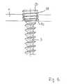
- FIG. 12is a schematic depiction of a bone screw having a conical male thread on the screw head.
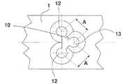
- FIG. 1 ais a schematic partial section through a bone plate 1 having a plate hole group 10 with a swivel hole 12 and a clamping hole 13 that are arranged at a pre-specified distance from one another, a swivel screw 2 being arranged in the swivel hole 12 and a clamping screw 3 being arranged in the clamping hole 13 .
- the swivel hole 12includes a tapering 120 that is selectively embodied in a positive fit with the screw head 20 of the swivel screw 2
- the clamping hole 13includes a tapering 130 that is selectively embodied in a positive fit with the screw head 30 of the clamping screw 3 .
- the swivel screw 2includes a spherically embodied screw head 20 that is flattened and in addition a hexagonal socket 24 for rotating the screw with a suitable tool.
- the swivel screw 2 depicted in FIG. 1 b without the bone plate 1has a thread for a bone screw 25 .
- a curved countersunk hole 131that corresponds to and is shaped to fit a curved countersunk head 31 of the screw head 30 of the clamping screw 3
- the clamping hole 13 adjacent to the tapering 130 of the clamping hole 13being cylindrically embodied
- a cylindrical sharp V female thread 132being embodied in the cylindrically embodied area of the clamping hole and corresponding to a cylindrical sharp V male thread 32 of the clamping screw 3 that connects to the screw head 30 of the clamping screw 3 .
- FIG. 1 cprovides a schematic depiction of the clamping screw 3 without the bone plate 1 with the screw head 30 , the curved countersunk head 31 of the screw head 30 , and the cylindrical sharp V male thread 32 , the clamping screw 3 also having in its screw head 30 a hexagonal socket 34 and including a thread for a bone screw 35 .
- the screw head 30 for the clamping screw 3is embodied to have a positive fit with the screw head 20 of the swivel screw 2 and consequently the clamping hole 13 with the correspondingly embodied tapering 130 is also embodied to have a positive fit with the screw head 30 of the clamping screw 3 .
- FIG. 1 of the bone plate 1 , the plate hole group 10 , and the swivel hole 12 and the clamping hole 13 and the swivel screw 2 and the clamping screw 3is particularly advantageous since due to the positive fit embodiment of the screw head 20 of the swivel screw 2 with the swivel hole 12 and with the screw head 30 of the clamping screw 3 and in addition due to the positive fit embodiment of the screw head 30 of the clamping screw 3 with the clamping hole 13 a particularly stable and durable locking up of bone plate 1 , swivel screw 2 , and clamping screw 3 is made possible.
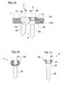
- FIG. 2 ais a modification of the bone plate 1 from FIG. 1 a having the swivel screw 2 and clamping screw 3
- FIGS. 2 b and 2 crespectively depict the swivel screw 2 and the clamping screw 3 from FIG. 2 a.
- the embodiment of the bone plate 1 in FIG. 2 ais embodied similar to the bone plate 1 in FIG. 1 a , the same reference numbers being used for identical and similar embodiments, and reference is made to the foregoing description of FIG. 1 for identical embodiments. The same is true for embodiments of the swivel screw 2 and the clamping screw 3 .
- the tapering 130 of the clamping hole 3is continuously conical and embodied in the conically embodied area of the clamping hole 13 is a sharp V female thread 133 that corresponds to the sharp V male thread 33 that is on the clamping screw 3 and that is embodied on a conically embodied countersunk head 30 of the clamping screw 3 that corresponds to the conically embodied clamping hole 13 .
- the bone plate 1also has a thickness compared to the screw heads 20 and 30 of the swivel screw 2 and of the clamping screw 3 , so that the screw heads 20 and 30 of the screws 2 and 3 can each be completely countersunk into their respective holes 12 and 13 of the plate hole group 10 , which advantageously provides a top side for the bone plate 1 without elevations from the screw heads 20 and 30 .
- FIGS. 1 and 2have in common that a distance between the holes 12 and 13 and the dimension of the plate hole group 10 and the dimensions of the screw heads 20 and 30 are selected in advance such that when the screws 2 and 3 are completely screwed into the bone plate 1 a fixed-angle clamping effect is provided between the screws 20 and 30 and between the screws 20 and 30 and the bone plate 1 .
- a combination of the embodiments in FIGS. 1 and 2may also be provided, for instance a bone plate 1 from FIG. 1 a that is embodied thicker so that the screw heads 20 and 30 from the embodiment in FIG. 1 may be completely countersunk into the plate hole group 10 .
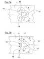
- FIGS. 3 a, b , and ceach provide a schematic top view onto a segment of a bone plate 1 having a plate hole group 10 with a swivel hole 12 for a swivel screw 2 and having a clamping hole 13 for a clamping screw 3 , the swivel hole 12 and the clamping hole 13 being embodied at least partly intermeshing, the swivel hole 12 and the clamping hole 13 also being arranged at a pre-specified distance A from one another so that when the screws 2 and 3 are completely rotated into the holes 12 and 13 the screw heads 20 and 30 of the screws 2 and 3 lock up with one another and with the edges of the holes 12 and 13 of the bone plate 1 and fixed-angle fixation of the swivel screw 2 and the clamping screw 3 is provided.
- the holes 12 and 13include in the area of the bone plate facing a bone taperings 120 and 130 that are suitably embodied corresponding to the respective screw heads 20 and 30 , and wherein a curved countersunk hole 131 and a cylindrical sharp V female thread 130 or a conical sharp V female thread 133 may be embodied on the clamping hole 13 .
- the holes 12 and 13intermesh with one another at least in a first area of the bone plate that is facing away from a bone, wherein the holes 12 and 13 may be spaced apart from one another in the area facing a bone, as is depicted schematically in the embodiment in FIG. 3 a.
- FIG. 3 bdepicts a modification of the bone plate 1 from FIG. 3 a in which the plate hole group 10 is advantageously embodied such that the intermeshing screw holes 12 and 13 form a contiguous through-hole.
- FIG. 3 cdepicts a particularly advantageous modification of the embodiment in FIG. 3 b in which sharp V female threaded columns 121 are embodied in the swivel hole 12 that support a positive and/or non-positive fit and the screw head 20 of the swivel screw 2 locks up with the bone plate 1 .
- sharp V female threaded columns 21may be embodied on the surface of the screw head 20 of the swivel head screw 2 that are also advantageously embodied corresponding to the sharp V female threaded columns 121 of the embodiment of the bone plate 1 in FIG. 3 c.
- FIG. 4 aprovides a schematic depiction of a screw head 20 of a swivel screw 2 having sharp V female threaded columns 21 .
- FIG. 4 bdepicts the screw head 20 in FIG. 4 a from above.
- the screw head 20 provided with the sharp V threaded columns in the embodiment of the swivel screw 2 in FIG. 4also promotes static friction and clamping with the bone plate 1 in FIG. 1 , FIG. 2 , FIGS. 3 a and 3 b , and with the clamping screw 3 in FIG. 1 and FIG. 2 .
- FIG. 5 ais a partial schematic depiction of a clamping screw 3 that is particularly suitable for a bone plate 1 and that has the screw head 30 and a sharp V male thread 33 embodied on the screw head 30 , the screw head 30 being embodied completely conical and being particularly suitable for a bone plate 1 from FIG. 2 a .
- FIG. 5 bis a partial schematic depiction of a screw 3 having the screw head 30 that is embodied conically 36 in a first area, to which is attached a cylindrically embodied area having a cylindrical sharp V male thread 32 , the clamping screw 3 in FIG. 5 b being particularly suitable for a combination (not shown in the drawings) of a bone plate 1 according to FIG. 1 a and FIG. 2 a with a clamping hole 13 that in a first area is embodied conically and in an area adjacent thereto is embodied cylindrically, the cylindrical area of the clamping hole 13 being provided with a corresponding sharp V female thread 32 .
- FIG. 5 cis a schematic depiction of a modification of the clamping screw 3 in FIG. 5 b , in which the screw head of the clamping screw 3 is embodied conically in a first 15 area and in a second adjacent area is embodied cylindrically, a cylindrical sharp V male thread 32 being embodied in the cylindrically embodied area.
- the clamping screw 3 in FIG. 5 cincludes on its conically embodied head 30 , instead of the conical surface of the countersunk head 20 of the clamping screw 3 in FIG.
- external radial ribs 360that provide particularly good static friction and clamping between the screw head 30 of the clamping screw 3 , with the bone plate 1 , and the screw head 20 of the swivel screw 2 .
- the countersunk headmay be provided with a conical male thread instead of the radial external ribs 360 .
- FIG. 6 ais a partial schematic depiction of a bone plate 1 according to another embodiment that is particularly suitable for fixing screws 3 according to FIG. 5 c , wherein the clamping hole 13 in the bone plate 1 in FIG. 6 a is conically embodied in a first area and in its conically embodied area can be provided without a thread 136 or with a sharp V female thread.
- the clamping hole 13is embodied cylindrically and provided with a cylindrical sharp V female thread 132 that corresponds to the cylindrical sharp V male thread 32 of the clamping screw 3 in FIG. 5 c , the height of the cylindrical area of the clamping hole 13 provided with the female thread 132 in FIG.
- FIG. 6 b in the bone plate 1advantageously being less than the height of the cylindrical area of the clamping screw 3 provided with the male thread 32 in FIG. 5 c so that the cylindrical area of the clamping; screw 3 when the clamping screw 3 is completely rotated into the bone plate 1 projects by a pre-specified amount beyond the side of the bone plate 1 facing a bone as depicted in FIG. 6 a , FIG. 6 b also depicts a section through the bone plate 1 along the line A-B in FIG. 6 a.
- FIG. 7 ais a schematic top view onto a bone plate 1 in accordance with another embodiment having a plate hole group 10 that includes two swivel holes 12 for swivel screws and also includes a clamping hole 13 for a clamping screw 3 .
- the holes 12 and 13are each embodied mutually intermeshing and are arranged at a pre-specified distance A.
- the plate hole group 10is embodied for instance and advantageously such that the intermeshing screw holes 12 and 13 form one contiguous through-hole.
- the distance A between clamping hole 13 and swivel hole 12is selected such that when the screws 2 and 3 are completely rotated into the holes 12 and 13 the screw heads 20 and 30 of the screws 2 and 3 lock up with one another and with the bone plate 1 so that fixed-angle fixation of swivel screw 2 and clamping screw 3 is provided.
- the clamping hole 13may be embodied in accordance with the embodiment from FIG. 1 or FIG. 2 or FIG. 6 .
- the swivel hole 12may be embodied in accordance with the swivel hole 12 from the embodiment in FIG.
- One plate hole group 10 of a bone plate 1may include a plurality of swivel holes 12 and/or clamping holes 13 , each of which are embodied intermeshed with one another.
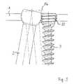
- FIG. 8provides a schematic depiction of a bone plate system having a bone plate 1 according to another embodiment, in which bone plate 1 the swivel hole 12 and the screw or clamping hole 13 associated with the swivel hole 12 are formed.
- the swivel hole 12is produced with a spherical head seat 80 that opens to the top 81 of the bone plate 1 .
- the spherical head seat 80is produced with an essentially smooth inner surface.
- the screw or clamping hole 13has a cylindrical female thread 82 that in the depicted embodiment extends across the entire height of the bone plate 1 from the top 81 to the bottom 83 .
- the swivel screw 2 embodied as bone screwis inserted into the swivel hole 12 such that the screw head 20 of the swivel screw 2 embodied as spherical head is disposed in the spherical head seat 80 essentially in a positive fit.
- the screw head 20 of the swivel screw 2which may also be called a spherical head screw, is provided with a thread contour 84 that is formed with essentially horizontal circumferential grooves 85 , a right-handed thread 86 , and a left-handed thread 87 . It can be provided that the right-handed and/or the left-handed thread 86 , 87 are embodied with multiple starts.
- the clamping screw 3Inserted into the screw or clamping hole 13 is the clamping screw 3 , also embodied as a bone screw, which has on its screw head 30 a conical male thread 88 that is rotated into the cylindrical female thread 82 of the screw or clamping hole 13 . Due to the cooperation between the cylindrical female thread 82 and the conical male thread 88 , the clamping screw 3 is essentially fixed in its position relative to the bone plate 1 , especially with respect to a spatial angular position to the bone plate 1 .
- FIG. 9is a schematic depiction of different angular or swivel positions of the swivel screw 2 , thread segments of the thread contour 84 and of the conical male thread 88 intermeshing in a positive fit in each of the swivel positions (solid lines and broken lines).
- FIG. 10is a schematic depiction relating to the cooperation between the conical male thread 88 and the cylindrical female thread 82 when the clamping screw 3 is screwed in.
- FIG. 11is a schematic depiction of the swivel screw 2 , the bone thread on the shaft 89 of the swivel screw 2 not being depicted as in FIGS. 1 and 2 . It may be embodied for instance in the same manner as for the clamping screw 3 (see FIGS. 8 through 10 ).
- FIG. 12is a schematic depiction of the clamping screw 3 .
- a bone thread 90is formed on the shaft 91 of the clamping screw 3 with an expanding segment 92 and with an essentially connecting transition area at the thread base 93 of the conical male thread 88 .
- Advantageous marking of the platesis also suggested in order to attain the most simple handling of the new plate-screw system possible during an operation. This is intended to achieve the most simple possible placement of the bone plate and addition of bone screws to screw holes.
- the identification or markingmay be accomplished using engraving and/or printing and/or galvanically.
- target devicescan be inserted in a minimally invasive manner using target devices.
- specially embodied target devicesare desirable in order to insert the plate-screw system for the suggested invention as safely as possible.
- the following featurescharacterize inter alia a target device embodied advantageously for the bone plate system:
- the bone platemay be used advantageously in fractures of the radius, humerus, femur, and tibia.
- a plate attachmentthat provides favorable bore directions for swivel holes and clamping holes is desirable.
- Features of a plate attachmentthat is particularly suitable for this are:
Landscapes
- Health & Medical Sciences (AREA)
- Orthopedic Medicine & Surgery (AREA)
- Surgery (AREA)
- Life Sciences & Earth Sciences (AREA)
- Heart & Thoracic Surgery (AREA)
- Nuclear Medicine, Radiotherapy & Molecular Imaging (AREA)
- Engineering & Computer Science (AREA)
- Biomedical Technology (AREA)
- Neurology (AREA)
- Medical Informatics (AREA)
- Molecular Biology (AREA)
- Animal Behavior & Ethology (AREA)
- General Health & Medical Sciences (AREA)
- Public Health (AREA)
- Veterinary Medicine (AREA)
- Surgical Instruments (AREA)
Abstract
Description
- Improved hold of a pair of divergent fixed-angle bone screws (or a plurality of fixed-angle screws) compared to one fixed-angle screw.
- Due to improved hold of the bone screws it is possible to use shorter or narrower bone plates.
- Due to improved hold of the bone screws the new system is particularly suitable for osteosynthesis of osteoporotic bones.
- More fixed-angle screws can be added in a small space at plate ends.
- In a short embodiment the clamping screw can simply lock up, or in a longer embodiment it can also be used as a monoaxial fixed-angle screw.
- Improved use in periprosthetic fractures.
- The swivel screw can draw bone fragments and then be fixed at a fixed angle by the clamping screw.
- Use of different implant materials such as pure titanium, titanium alloys, and other steel/metal implant alloys;
- Different surface hardening of various components (for instance particular hardness for the fixing screw).
- Radial thread or radial ribs of limited height on the surface of the swivel hole and/or on the surface of the clamping hole. Naturally one or a plurality of threads or ribs may be embodied in any other desired configurations.
- Longitudinal thread or longitudinal ribs of limited height on the surface of the swivel screw and/or on the surface of the fixing screw. Naturally one or a plurality of threads or ribs may be embodied in any other desired configurations.
- Surface roughness of the swivel hole and/or of the clamping hole and/or of the swivel screw head and/or of the fixing screw countersunk head (for instance by sandblasting).
- Soft surface of the round head of the swivel screw (so that a harder thread for the cone of the clamping screw can bite into the softer spherical head).
- Covering of the spherical head of the swivel screw with a biocompatible non-metallic material (especially polypropylene) or a transition metal (for instance tantalum). It is clear that resorbable biocompatible materials may also be used for the covering of the spherical head (for instance lactide). Due to the spherical head of the swivel screw being covered, a thread on the fixing screw head can dig into the softer covering on the swivel screw head. The biocompatible material should have a rough and low-wear surface.
- Modified thread shapes such as for instance PG thread, NPT thread, trapezoidal thread, spherical thread.
- Modified fixing screw geometry such as for instance embodiment as an oval head or pear-shaped head or modified screw head geometry like a concave or concave-like free shape for the head geometry in order to attain a positive fit with the head of the swivel screw.
- Anatomically molded plates in the joint areas for long bones, for instance the long bones in the extremities
- Balancing of materials in plate holes and plate hole groups in order to facilitate favorable bending in the area between holes
- No holes in plates in order to make it possible to fix the bone plate to the bones, for instance using wires, and (ii) to be able to fix threads or anchors to the bone plate.
- Target device with retention apparatus for the plate
- Retention apparatus for the bone plate can be attached to the bone plate for instance using threads on sleeves that grip in one clamping hole or a plurality of clamping holes
- Target device includes one or a plurality of additional holes for wires for temporary plate fixation
- Target device is characterized by different markings for swivel screws and fixed screws. Marking may be produced for instance by engraving and/or printing.
- One or a plurality of placeable jaws may be fixed on the target device for adding swivel holes. A placeable jaw is provided with an apparatus that can be used as a variably adjustable target apparatus for swivel screws. The target apparatus guides for instance a bushing (for receiving bore sleeves or sleeves for guiding screws) perpendicular to a curved surface of a spherical segment, the center point of the sphere coinciding or nearly coinciding with the center point of the swivel screw hole.
- The plate attachment has a thickness that is multiple times thicker than the bone plate (for instance three times thicker) and includes bores in directions that can typically or favorably be used in the respective joint regions.
- The plate attachment includes markings for swivel holes and clamping holes.
- The plate attachment can be provided with notations for common screw lengths. The notation can be applied for instance using engraving and/or printing.
- The plate attachment includes one or a plurality of additional holes for wires for temporarily attaching the bone plate to the bone.
- A clamping or screw mechanism permits rapid coupling of the plate attachment to the plate.
Claims (18)
Applications Claiming Priority (7)
| Application Number | Priority Date | Filing Date | Title |
|---|---|---|---|
| DE102009060396.4 | 2009-12-22 | ||
| DE102009060396 | 2009-12-22 | ||
| DE102009060396.4ADE102009060396B4 (en) | 2009-12-22 | 2009-12-22 | Bone plate with device for angular stable screw fixation and screws therefor |
| DE201020005260DE202010005260U1 (en) | 2010-04-20 | 2010-04-20 | Bone plate system and kit |
| DE202010005260.2 | 2010-04-20 | ||
| DE202010005260 | 2010-04-20 | ||
| PCT/DE2010/075167WO2011076205A1 (en) | 2009-12-22 | 2010-12-21 | Bone plate system for osteosynthesis |
Publications (2)
| Publication Number | Publication Date |
|---|---|
| US20130165981A1 US20130165981A1 (en) | 2013-06-27 |
| US9161795B2true US9161795B2 (en) | 2015-10-20 |
Family
ID=43799502
Family Applications (1)
| Application Number | Title | Priority Date | Filing Date |
|---|---|---|---|
| US13/517,949Expired - Fee RelatedUS9161795B2 (en) | 2009-12-22 | 2010-12-21 | Bone plate system for osteosynthesis |
Country Status (4)
| Country | Link |
|---|---|
| US (1) | US9161795B2 (en) |
| EP (1) | EP2515779B1 (en) |
| ES (1) | ES2573811T3 (en) |
| WO (1) | WO2011076205A1 (en) |
Cited By (34)
| Publication number | Priority date | Publication date | Assignee | Title |
|---|---|---|---|---|
| US20130060291A1 (en)* | 2011-09-06 | 2013-03-07 | Samuel Petersheim | Spinal Plate |
| US10335213B2 (en) | 2015-03-11 | 2019-07-02 | Königsee Implantate GmbH | Bone plate with a bone screw |
| US10368928B2 (en) | 2017-03-13 | 2019-08-06 | Globus Medical, Inc. | Bone stabilization systems |
| US10383668B2 (en) | 2016-08-17 | 2019-08-20 | Globus Medical, Inc. | Volar distal radius stabilization system |
| US10420596B2 (en) | 2016-08-17 | 2019-09-24 | Globus Medical, Inc. | Volar distal radius stabilization system |
| US10575884B2 (en) | 2016-08-17 | 2020-03-03 | Globus Medical, Inc. | Fracture plates, systems, and methods |
| US10631903B2 (en) | 2017-03-10 | 2020-04-28 | Globus Medical Inc. | Clavicle fixation system |
| US10687874B2 (en) | 2015-08-27 | 2020-06-23 | Globus Medical, Inc | Proximal humeral stabilization system |
| US10687873B2 (en) | 2016-08-17 | 2020-06-23 | Globus Medical Inc. | Stabilization systems |
| US10751098B2 (en) | 2016-08-17 | 2020-08-25 | Globus Medical Inc. | Stabilization systems |
| US10828075B2 (en) | 2015-09-25 | 2020-11-10 | Globus Medical Inc. | Bone fixation devices having a locking feature |
| US10828074B2 (en) | 2015-11-20 | 2020-11-10 | Globus Medical, Inc. | Expandalbe intramedullary systems and methods of using the same |
| US10856920B2 (en) | 2017-09-13 | 2020-12-08 | Globus Medical Inc. | Bone stabilization systems |
| US10905477B2 (en) | 2017-03-13 | 2021-02-02 | Globus Medical, Inc. | Bone stabilization systems |
| US11071570B2 (en) | 2018-03-02 | 2021-07-27 | Globus Medical, Inc. | Distal tibial plating system |
| US11076898B2 (en) | 2015-08-27 | 2021-08-03 | Globus Medical, Inc. | Proximal humeral stabilization system |
| US11096730B2 (en) | 2017-09-13 | 2021-08-24 | Globus Medical Inc. | Bone stabilization systems |
| US11129627B2 (en) | 2019-10-30 | 2021-09-28 | Globus Medical, Inc. | Method and apparatus for inserting a bone plate |
| US11141204B2 (en) | 2016-08-17 | 2021-10-12 | Globus Medical Inc. | Wrist stabilization systems |
| US11141172B2 (en) | 2018-04-11 | 2021-10-12 | Globus Medical, Inc. | Method and apparatus for locking a drill guide in a polyaxial hole |
| US11197704B2 (en) | 2016-04-19 | 2021-12-14 | Globus Medical, Inc. | Implantable compression screws |
| US11197701B2 (en) | 2016-08-17 | 2021-12-14 | Globus Medical, Inc. | Stabilization systems |
| US11197682B2 (en) | 2015-08-27 | 2021-12-14 | Globus Medical, Inc. | Proximal humeral stabilization system |
| US11202663B2 (en) | 2019-02-13 | 2021-12-21 | Globus Medical, Inc. | Proximal humeral stabilization systems and methods thereof |
| US11213327B2 (en) | 2016-08-17 | 2022-01-04 | Globus Medical, Inc. | Fracture plates, systems, and methods |
| US11224468B2 (en) | 2018-03-02 | 2022-01-18 | Globus Medical, Inc. | Distal tibial plating system |
| US11284920B2 (en) | 2016-03-02 | 2022-03-29 | Globus Medical Inc. | Fixators for bone stabilization and associated systems and methods |
| US11331128B2 (en) | 2016-08-17 | 2022-05-17 | Globus Medical Inc. | Distal radius stabilization system |
| US11432857B2 (en) | 2016-08-17 | 2022-09-06 | Globus Medical, Inc. | Stabilization systems |
| US11723647B2 (en) | 2019-12-17 | 2023-08-15 | Globus Medical, Inc. | Syndesmosis fixation assembly |
| US12042200B2 (en) | 2016-09-22 | 2024-07-23 | Globus Medical, Inc. | Systems and methods for intramedullary nail implantation |
| US12064150B2 (en) | 2022-01-19 | 2024-08-20 | Globus Medical Inc. | System and method for treating bone fractures |
| US12185995B2 (en) | 2019-10-09 | 2025-01-07 | Globus Medical, Inc. | Bone stabilization systems |
| US12279795B2 (en) | 2017-09-13 | 2025-04-22 | Globus Medical, Inc. | Bone stabilization systems |
Families Citing this family (13)
| Publication number | Priority date | Publication date | Assignee | Title |
|---|---|---|---|---|
| DE102009016394B4 (en) | 2009-04-07 | 2016-02-11 | Merete Medical Gmbh | Device for stable-angle fixation and compression of a fracture site or osteotomy on a bone |
| EP2515779B1 (en) | 2009-12-22 | 2016-03-02 | Merete Medical GmbH | Bone plate system for osteosynthesis |
| WO2013059090A1 (en)* | 2011-10-17 | 2013-04-25 | Biomet Trauma, LLC | Variable locking bone plating system |
| US20130261673A1 (en)* | 2012-03-28 | 2013-10-03 | John Riley Hawkins | Quad anchor lateral vertebral body fixation plates |
| DE102012103894B4 (en) | 2012-05-03 | 2016-10-27 | Merete Medical Gmbh | Bone plate system for osteosynthesis |
| US20150238233A1 (en)* | 2012-08-09 | 2015-08-27 | Trinity Orthopedics, Llc | Intervertebral Plate Systems and Methods of Use |
| US9480516B2 (en)* | 2013-09-09 | 2016-11-01 | Globus Medical, Inc. | Percutaneous bone screw device and method |
| CN105596075A (en)* | 2014-11-13 | 2016-05-25 | 无锡市闻泰百得医疗器械有限公司 | Bone plate screw structure |
| CN105213017A (en)* | 2015-10-29 | 2016-01-06 | 创辉医疗器械江苏有限公司 | Lock screw that multi-angle is adjustable |
| US10265109B2 (en) | 2016-02-02 | 2019-04-23 | Life Spine, Inc. | Spine plate implant with cam lock bone screw retention |
| TR201908745A2 (en)* | 2019-06-13 | 2020-12-21 | Efa Veterinerlik Hizmetleri Tic Ltd Sti | FULLY ANATOMIC POLYAXIAL LOCKING DISTAL FEMUR PLATE DESIGNED FOR FOUR-LEGED ANIMALS |
| CN110801273B (en)* | 2019-12-05 | 2024-08-20 | 成都美益达医疗科技有限公司 | Bone repair fixing assembly capable of pre-tightening and stopping |
| CN119970203B (en)* | 2025-04-17 | 2025-07-15 | 北京贝思达生物技术有限公司 | Locking metal bone fracture plate |
Citations (85)
| Publication number | Priority date | Publication date | Assignee | Title |
|---|---|---|---|---|
| US2662988A (en) | 1948-07-15 | 1953-12-15 | Gen Electric | Base for motors |
| US3741205A (en) | 1971-06-14 | 1973-06-26 | K Markolf | Bone fixation plate |
| US3757591A (en) | 1970-09-30 | 1973-09-11 | Cambridge Scientific Instr Ltd | Disengageable nut and screw arrangement |
| DE3113639A1 (en) | 1980-04-14 | 1982-05-06 | Wilhelm Wenk AG, 4614 Hägendorf | OSTEOSYNTHETIC COMPRESSION PLATE |
| US4454876A (en) | 1982-05-25 | 1984-06-19 | University Of Pittsburgh | Pelvic fixation plate and method of implanting same |
| US4616634A (en) | 1985-03-07 | 1986-10-14 | Commonwealth Of Puerto Rico | Soft tissue protector for use in oral and maxillofacial surgery |
| EP0243114A1 (en) | 1986-04-19 | 1987-10-28 | LUCAS INDUSTRIES public limited company | Improvements relating to disc brakes |
| US4720225A (en) | 1985-11-28 | 1988-01-19 | Itw Limited | Threaded fastening systems |
| US4903691A (en) | 1986-01-22 | 1990-02-27 | Thomas Heinl | Set of surgical instruments for joining bone fragments |
| US4959065A (en) | 1989-07-14 | 1990-09-25 | Techmedica, Inc. | Bone plate with positioning member |
| FR2667913A1 (en) | 1990-10-16 | 1992-04-17 | Biomecanique Integree | System for assembling at least two elements using a screw or the like |
| US5529075A (en) | 1994-09-12 | 1996-06-25 | Clark; David | Fixation device and method for repair of pronounced hallux valgus |
| WO1997009000A1 (en) | 1995-09-06 | 1997-03-13 | Synthes Ag Chur | Bone plate |
| FR2739151A1 (en) | 1995-09-22 | 1997-03-28 | Numedic | Fixing screw for bone implants |
| US5709686A (en) | 1995-03-27 | 1998-01-20 | Synthes (U.S.A.) | Bone plate |
| WO1998029058A1 (en) | 1996-12-31 | 1998-07-09 | M.P.R.S. Ltd. | A modular implant for pelvis reconstruction |
| AT406446B (en) | 1997-09-09 | 2000-05-25 | Werner Ing Fuchs | ANGLE-STABLE SCREW CONNECTION |
| WO2000053110A1 (en) | 1999-03-09 | 2000-09-14 | Synthes Ag Chur | Bone plate |
| US6129728A (en) | 1998-02-18 | 2000-10-10 | Walter Lorenz Surgical, Inc. | Method and apparatus for mandibular osteosynthesis |
| US6152927A (en)* | 1997-05-15 | 2000-11-28 | Sdgi Holdings, Inc. | Anterior cervical plating system |
| US6203545B1 (en) | 1996-03-26 | 2001-03-20 | Waldemar Link (Gmbh & Co.) | Implant for fixing bone fragments after an osteotomy |
| US6206883B1 (en) | 1999-03-05 | 2001-03-27 | Stryker Technologies Corporation | Bioabsorbable materials and medical devices made therefrom |
| WO2001054601A1 (en) | 2000-01-27 | 2001-08-02 | Synthes Ag Chur | Bone plate |
| US6293949B1 (en)* | 2000-03-01 | 2001-09-25 | Sdgi Holdings, Inc. | Superelastic spinal stabilization system and method |
| US6306140B1 (en) | 2001-01-17 | 2001-10-23 | Synthes (Usa) | Bone screw |
| EP1158916A1 (en) | 1999-03-09 | 2001-12-05 | SYNTHES AG Chur | Bone plate with conical screw threads |
| US20020045897A1 (en) | 2000-10-16 | 2002-04-18 | Dixon Robert A. | Method and apparatus utilizing interference fit screw shanks for nonmetallic spinal stabilization |
| US6398783B1 (en) | 1997-02-11 | 2002-06-04 | Sulzer Spine-Tech Inc. | Multi-lock anterior cervical plate |
| US6423068B1 (en) | 2000-10-18 | 2002-07-23 | Erhard Reisberg | Method and apparatus for mandibular osteosynthesis |
| WO2002096309A1 (en) | 2001-05-28 | 2002-12-05 | Synthes Ag Chur | Bone plate for the fixation of fractures of the proximal humerus |
| US20030078668A1 (en) | 1999-05-05 | 2003-04-24 | Michelson Gary K. | Interbody spinal fusion implants with single-lock for locking opposed screws |
| US20040018228A1 (en) | 2000-11-06 | 2004-01-29 | Afmedica, Inc. | Compositions and methods for reducing scar tissue formation |
| US20040034356A1 (en) | 2002-07-16 | 2004-02-19 | Lehuec Jean-Charles | Plating system for stabilizing a bony segment |
| US20040073218A1 (en) | 2002-10-15 | 2004-04-15 | The University Of North Carolina At Chapel Hill | Multi-angular fastening apparatus and method for surgical bone screw/plate systems |
| US6730091B1 (en) | 1999-05-03 | 2004-05-04 | Medartis Ag | Blockable bone plate |
| US20040102778A1 (en) | 2002-11-19 | 2004-05-27 | Huebner Randall J. | Adjustable bone plates |
| EP1468655A2 (en) | 2003-03-26 | 2004-10-20 | Precimed S.A. | Locking bone plate |
| US20050015092A1 (en) | 2003-07-16 | 2005-01-20 | Rathbun David S. | Plating system with multiple function drill guide |
| US20050049594A1 (en) | 2001-04-20 | 2005-03-03 | Wack Michael A. | Dual locking plate and associated method |
| US20050065521A1 (en) | 2002-02-22 | 2005-03-24 | Steger Shon D. | Method and apparatus for bone fracture fixation |
| US20050085818A1 (en) | 2003-10-17 | 2005-04-21 | Huebner Randall J. | Systems for distal radius fixation |
| US6886799B2 (en) | 2002-02-27 | 2005-05-03 | Denso Corporation | Structure for mounting heavy article to carrier body |
| WO2005041769A1 (en) | 2003-10-31 | 2005-05-12 | Otsuka Pharmaceutical Co., Ltd. | Gas injection amount determining method in isotope gas analysis, and isotope gas analyzing and measuring method and apparatus |
| WO2005041796A1 (en) | 2003-10-30 | 2005-05-12 | Synthes Gmbh | Bone plate |
| US20050124994A1 (en) | 2001-02-21 | 2005-06-09 | Synthes (Usa) | Occipital plate and system for spinal stabilization |
| WO2005053111A1 (en) | 2003-11-24 | 2005-06-09 | Panduit Corp. | Communications patch panel systems and methods |
| US20050165400A1 (en) | 2004-01-26 | 2005-07-28 | Fernandez Alberto A. | Variable angle locked bone fixation system |
| US20050165401A1 (en) | 2004-01-26 | 2005-07-28 | Larry Pack | Pelvic fixation plate |
| US20050182408A1 (en) | 1999-05-25 | 2005-08-18 | Medartis Ag | Osteosynthetic bone plate |
| US20050192577A1 (en) | 2004-02-26 | 2005-09-01 | Pioneer Laboratories, Inc. | Bone plate system and methods |
| US20050261688A1 (en) | 2004-05-11 | 2005-11-24 | Grady Mark P Jr | Bone plate |
| US20060015102A1 (en) | 2004-07-15 | 2006-01-19 | Toullec Eric R M | Fastener implant for osteosynthesis of fragments of a first metatarsal bone that is broken or osteotomized in its proximal portion and a corresponding osteosynthesis method |
| WO2006014436A1 (en) | 2004-07-07 | 2006-02-09 | Depuy Products, Inc. | Bone plate system with bone screws fixed by secondary compression |
| US7008428B2 (en) | 1996-11-12 | 2006-03-07 | Triage Medical, Inc. | Bone fixation system |
| DE102005044841A1 (en) | 2004-09-21 | 2006-03-23 | Deyssig, Roman, , Dr. med. Univ. | Suction device for removal of surplus of dental impression material, comprising adjusting device for suction forces |
| US20060173458A1 (en) | 2004-10-07 | 2006-08-03 | Micah Forstein | Bone fracture fixation system |
| DE102006000948A1 (en) | 2005-04-11 | 2006-10-19 | Aap Implantate Ag | Bone plate, has thread fixing head or neck of screw and including longitudinal axis that extends within guiding surface and cuts plane at angle that is different from ninety degrees |
| US20060235396A1 (en) | 2005-03-31 | 2006-10-19 | Roy Sanders | Fixation device for the talus |
| US20060241607A1 (en) | 2005-03-31 | 2006-10-26 | Mark Myerson | Metatarsal fixation plate |
| FR2886535A1 (en) | 2005-06-06 | 2006-12-08 | Surfix Technologies Sa | DEVICE FOR ARRESSING A SUPPORT, ASSEMBLY PART FOR SUCH A DEVICE AND METHOD OF ARRANGING A DEVICE TO A SUPPORT |
| DE102005043285B3 (en) | 2005-09-09 | 2007-01-04 | Dieter Marquardt Medizintechnik Gmbh | Bone plate for the treatment of proximal humeral fractures |
| WO2007025520A1 (en) | 2005-09-01 | 2007-03-08 | Merete Medical Gmbh | Bone plate comprising at least one screw to be fixed at a stable angle |
| US20070123885A1 (en) | 2003-09-30 | 2007-05-31 | X-Spine Systems, Inc. | Screw locking mechanism and method |
| US20070233106A1 (en) | 2006-02-24 | 2007-10-04 | Synthes (Usa) | Tibal plateau leveling osteotomy plate |
| US20070276386A1 (en) | 2003-09-29 | 2007-11-29 | Darin Gerlach | Bone plate systems using provisional fixation |
| US20080051786A1 (en) | 2006-04-03 | 2008-02-28 | Acumed Llc | Bone plates with hybrid apertures |
| EP1897509A1 (en) | 2006-09-11 | 2008-03-12 | Surge Foot | Arthrodesis plate for a metatarsal-phalanges joint |
| DE102007005417A1 (en) | 2006-12-19 | 2008-06-26 | Zrinski Ag | Plate implant, in particular for use on a spinal column, with a screw closure system |
| US20080300637A1 (en) | 2005-07-25 | 2008-12-04 | Smith & Nephew, Inc. | Systems and methods for using polyaxial plates |
| US7468069B2 (en) | 2004-02-10 | 2008-12-23 | Atlas Spine, Inc. | Static anterior cervical plate |
| EP2016918A1 (en) | 2007-07-18 | 2009-01-21 | Mario Angel Pizzicara | Blocked plate with combined holes, stability control and double angulation, to join fractured bones |
| WO2009058969A1 (en) | 2007-10-30 | 2009-05-07 | Synthes (U.S.A.) | Variable angle locked bone plate |
| DE102005042766B4 (en) | 2005-07-13 | 2009-08-20 | Königsee Implantate und Instrumente zur Osteosynthese GmbH | Plate hole of a bone plate for osteosynthesis |
| US20090210010A1 (en) | 2008-02-19 | 2009-08-20 | Orthohelix Surgical Designs, Inc. | Orthopedic plate for use in the MTP joint |
| WO2010059497A1 (en) | 2008-11-19 | 2010-05-27 | Amei Technologies, Inc. | Fixation plate for use in the lapidus approach |
| US7771457B2 (en) | 2005-01-28 | 2010-08-10 | Orthohelix Surgical Designs, Inc. | Orthopedic plate for use in small bone repair |
| US20100256687A1 (en) | 2009-04-01 | 2010-10-07 | Merete Medical Gmbh | Fixation Device and Method of Use for a Ludloff Osteotomy Procedure |
| WO2010115403A1 (en) | 2009-04-07 | 2010-10-14 | Merete Medical Gmbh | Apparatus for the constant-angle fixation and compression of a fracture or osteotomy of a bone |
| WO2011076205A1 (en) | 2009-12-22 | 2011-06-30 | Merete Medical Gmbh | Bone plate system for osteosynthesis |
| US20110264149A1 (en) | 2010-04-27 | 2011-10-27 | Dana Pappalardo | Bone fixation system including k-wire compression |
| WO2011163092A2 (en) | 2010-06-25 | 2011-12-29 | Amit Gupta | Plate system for managing a bone fracture |
| DE102010025001A1 (en) | 2010-06-24 | 2011-12-29 | Aap Implantate Ag | bone plate |
| WO2012000627A1 (en) | 2010-06-30 | 2012-01-05 | Aap Implantate Ag | Fixation system for bones |
| US8118848B2 (en) | 2005-01-28 | 2012-02-21 | Orthohelix Surgical Designs, Inc. | Orthopedic plate for use in fibula repair |
| US8632545B2 (en) | 2007-08-27 | 2014-01-21 | Adler Mediequip Private Limited | Bone plates and bone plate assemblies |
- 2010
- 2010-12-21EPEP10805682.1Apatent/EP2515779B1/ennot_activeNot-in-force
- 2010-12-21USUS13/517,949patent/US9161795B2/ennot_activeExpired - Fee Related
- 2010-12-21ESES10805682.1Tpatent/ES2573811T3/enactiveActive
- 2010-12-21WOPCT/DE2010/075167patent/WO2011076205A1/enactiveApplication Filing
Patent Citations (109)
| Publication number | Priority date | Publication date | Assignee | Title |
|---|---|---|---|---|
| US2662988A (en) | 1948-07-15 | 1953-12-15 | Gen Electric | Base for motors |
| US3757591A (en) | 1970-09-30 | 1973-09-11 | Cambridge Scientific Instr Ltd | Disengageable nut and screw arrangement |
| US3741205A (en) | 1971-06-14 | 1973-06-26 | K Markolf | Bone fixation plate |
| DE3113639A1 (en) | 1980-04-14 | 1982-05-06 | Wilhelm Wenk AG, 4614 Hägendorf | OSTEOSYNTHETIC COMPRESSION PLATE |
| US4408601A (en) | 1980-04-14 | 1983-10-11 | Wilh, Wenk Ag | Bone compression plate |
| US4454876A (en) | 1982-05-25 | 1984-06-19 | University Of Pittsburgh | Pelvic fixation plate and method of implanting same |
| US4616634A (en) | 1985-03-07 | 1986-10-14 | Commonwealth Of Puerto Rico | Soft tissue protector for use in oral and maxillofacial surgery |
| US4720225A (en) | 1985-11-28 | 1988-01-19 | Itw Limited | Threaded fastening systems |
| US4903691A (en) | 1986-01-22 | 1990-02-27 | Thomas Heinl | Set of surgical instruments for joining bone fragments |
| EP0243114A1 (en) | 1986-04-19 | 1987-10-28 | LUCAS INDUSTRIES public limited company | Improvements relating to disc brakes |
| US4959065A (en) | 1989-07-14 | 1990-09-25 | Techmedica, Inc. | Bone plate with positioning member |
| FR2667913A1 (en) | 1990-10-16 | 1992-04-17 | Biomecanique Integree | System for assembling at least two elements using a screw or the like |
| US5529075A (en) | 1994-09-12 | 1996-06-25 | Clark; David | Fixation device and method for repair of pronounced hallux valgus |
| US5709686A (en) | 1995-03-27 | 1998-01-20 | Synthes (U.S.A.) | Bone plate |
| WO1997009000A1 (en) | 1995-09-06 | 1997-03-13 | Synthes Ag Chur | Bone plate |
| FR2739151A1 (en) | 1995-09-22 | 1997-03-28 | Numedic | Fixing screw for bone implants |
| US6203545B1 (en) | 1996-03-26 | 2001-03-20 | Waldemar Link (Gmbh & Co.) | Implant for fixing bone fragments after an osteotomy |
| US7008428B2 (en) | 1996-11-12 | 2006-03-07 | Triage Medical, Inc. | Bone fixation system |
| WO1998029058A1 (en) | 1996-12-31 | 1998-07-09 | M.P.R.S. Ltd. | A modular implant for pelvis reconstruction |
| US6398783B1 (en) | 1997-02-11 | 2002-06-04 | Sulzer Spine-Tech Inc. | Multi-lock anterior cervical plate |
| DE69835968T2 (en) | 1997-05-15 | 2007-05-24 | Warsaw Orthopedic, Inc., Minneapolis | System for the front plating of the cervical spine |
| US6152927A (en)* | 1997-05-15 | 2000-11-28 | Sdgi Holdings, Inc. | Anterior cervical plating system |
| EP1702577A2 (en) | 1997-05-15 | 2006-09-20 | SDGI Holdings, Inc. | Anterior cervical plating system |
| AT406446B (en) | 1997-09-09 | 2000-05-25 | Werner Ing Fuchs | ANGLE-STABLE SCREW CONNECTION |
| US6129728A (en) | 1998-02-18 | 2000-10-10 | Walter Lorenz Surgical, Inc. | Method and apparatus for mandibular osteosynthesis |
| US6206883B1 (en) | 1999-03-05 | 2001-03-27 | Stryker Technologies Corporation | Bioabsorbable materials and medical devices made therefrom |
| US6716957B2 (en) | 1999-03-05 | 2004-04-06 | Stryker Technologies Corporation | Bioabsorbable materials and medical devices made therefrom |
| EP1158915A1 (en) | 1999-03-09 | 2001-12-05 | SYNTHES AG Chur | Bone plate |
| US20020045901A1 (en) | 1999-03-09 | 2002-04-18 | Michael Wagner | Bone plate |
| WO2000053110A1 (en) | 1999-03-09 | 2000-09-14 | Synthes Ag Chur | Bone plate |
| EP1158916A1 (en) | 1999-03-09 | 2001-12-05 | SYNTHES AG Chur | Bone plate with conical screw threads |
| US20110295325A1 (en) | 1999-03-09 | 2011-12-01 | Michael Wagner | Bone Plate |
| US7976570B2 (en) | 1999-03-09 | 2011-07-12 | Synthes Usa, Llc | Bone plate |
| US6719759B2 (en) | 1999-03-09 | 2004-04-13 | Synthes Ag Chur | Bone plate |
| US6730091B1 (en) | 1999-05-03 | 2004-05-04 | Medartis Ag | Blockable bone plate |
| US20030078668A1 (en) | 1999-05-05 | 2003-04-24 | Michelson Gary K. | Interbody spinal fusion implants with single-lock for locking opposed screws |
| US20050182408A1 (en) | 1999-05-25 | 2005-08-18 | Medartis Ag | Osteosynthetic bone plate |
| EP1255498A1 (en) | 2000-01-27 | 2002-11-13 | SYNTHES AG Chur | Bone plate |
| US7354441B2 (en) | 2000-01-27 | 2008-04-08 | Synthes (U.S.A.) | Bone plate |
| US6669701B2 (en) | 2000-01-27 | 2003-12-30 | Synthes (Usa) | Bone plate |
| US20080132955A1 (en) | 2000-01-27 | 2008-06-05 | Robert Frigg | Bone Plate |
| US20020183752A1 (en) | 2000-01-27 | 2002-12-05 | Beatrice Steiner | Bone plate |
| US20040236332A1 (en) | 2000-01-27 | 2004-11-25 | Synthes Ag Chur And Synthes (Usa) | Bone plate |
| WO2001054601A1 (en) | 2000-01-27 | 2001-08-02 | Synthes Ag Chur | Bone plate |
| US6293949B1 (en)* | 2000-03-01 | 2001-09-25 | Sdgi Holdings, Inc. | Superelastic spinal stabilization system and method |
| US20040215192A1 (en) | 2000-03-01 | 2004-10-28 | Justis Jeff R | Superelastic spinal stabilization system and method |
| US20020045897A1 (en) | 2000-10-16 | 2002-04-18 | Dixon Robert A. | Method and apparatus utilizing interference fit screw shanks for nonmetallic spinal stabilization |
| US6423068B1 (en) | 2000-10-18 | 2002-07-23 | Erhard Reisberg | Method and apparatus for mandibular osteosynthesis |
| US20040018228A1 (en) | 2000-11-06 | 2004-01-29 | Afmedica, Inc. | Compositions and methods for reducing scar tissue formation |
| US6306140B1 (en) | 2001-01-17 | 2001-10-23 | Synthes (Usa) | Bone screw |
| US20050124994A1 (en) | 2001-02-21 | 2005-06-09 | Synthes (Usa) | Occipital plate and system for spinal stabilization |
| US20050049594A1 (en) | 2001-04-20 | 2005-03-03 | Wack Michael A. | Dual locking plate and associated method |
| US7655029B2 (en) | 2001-05-28 | 2010-02-02 | Synthes Usa, Llc | Bone plate |
| WO2002096309A1 (en) | 2001-05-28 | 2002-12-05 | Synthes Ag Chur | Bone plate for the fixation of fractures of the proximal humerus |
| US20040167522A1 (en) | 2001-05-28 | 2004-08-26 | Alfred Niederberger | Bone plate |
| US20050065521A1 (en) | 2002-02-22 | 2005-03-24 | Steger Shon D. | Method and apparatus for bone fracture fixation |
| US6886799B2 (en) | 2002-02-27 | 2005-05-03 | Denso Corporation | Structure for mounting heavy article to carrier body |
| US20040034356A1 (en) | 2002-07-16 | 2004-02-19 | Lehuec Jean-Charles | Plating system for stabilizing a bony segment |
| US20040073218A1 (en) | 2002-10-15 | 2004-04-15 | The University Of North Carolina At Chapel Hill | Multi-angular fastening apparatus and method for surgical bone screw/plate systems |
| US20040102778A1 (en) | 2002-11-19 | 2004-05-27 | Huebner Randall J. | Adjustable bone plates |
| EP1468655A2 (en) | 2003-03-26 | 2004-10-20 | Precimed S.A. | Locking bone plate |
| US20050015092A1 (en) | 2003-07-16 | 2005-01-20 | Rathbun David S. | Plating system with multiple function drill guide |
| US20070276386A1 (en) | 2003-09-29 | 2007-11-29 | Darin Gerlach | Bone plate systems using provisional fixation |
| US20070123885A1 (en) | 2003-09-30 | 2007-05-31 | X-Spine Systems, Inc. | Screw locking mechanism and method |
| US20050085818A1 (en) | 2003-10-17 | 2005-04-21 | Huebner Randall J. | Systems for distal radius fixation |
| WO2005041796A1 (en) | 2003-10-30 | 2005-05-12 | Synthes Gmbh | Bone plate |
| EP1677693A1 (en) | 2003-10-30 | 2006-07-12 | Synthes GmbH | Bone plate |
| US8246661B2 (en) | 2003-10-30 | 2012-08-21 | Synthes Usa, Llc | Bone plate |
| US20070016205A1 (en) | 2003-10-30 | 2007-01-18 | Florian Beutter | Bone plate |
| WO2005041769A1 (en) | 2003-10-31 | 2005-05-12 | Otsuka Pharmaceutical Co., Ltd. | Gas injection amount determining method in isotope gas analysis, and isotope gas analyzing and measuring method and apparatus |
| WO2005053111A1 (en) | 2003-11-24 | 2005-06-09 | Panduit Corp. | Communications patch panel systems and methods |
| US20050165400A1 (en) | 2004-01-26 | 2005-07-28 | Fernandez Alberto A. | Variable angle locked bone fixation system |
| US20050165401A1 (en) | 2004-01-26 | 2005-07-28 | Larry Pack | Pelvic fixation plate |
| US7468069B2 (en) | 2004-02-10 | 2008-12-23 | Atlas Spine, Inc. | Static anterior cervical plate |
| US20050192577A1 (en) | 2004-02-26 | 2005-09-01 | Pioneer Laboratories, Inc. | Bone plate system and methods |
| US20050261688A1 (en) | 2004-05-11 | 2005-11-24 | Grady Mark P Jr | Bone plate |
| WO2006014436A1 (en) | 2004-07-07 | 2006-02-09 | Depuy Products, Inc. | Bone plate system with bone screws fixed by secondary compression |
| US20060015102A1 (en) | 2004-07-15 | 2006-01-19 | Toullec Eric R M | Fastener implant for osteosynthesis of fragments of a first metatarsal bone that is broken or osteotomized in its proximal portion and a corresponding osteosynthesis method |
| DE102005044841A1 (en) | 2004-09-21 | 2006-03-23 | Deyssig, Roman, , Dr. med. Univ. | Suction device for removal of surplus of dental impression material, comprising adjusting device for suction forces |
| US20060173458A1 (en) | 2004-10-07 | 2006-08-03 | Micah Forstein | Bone fracture fixation system |
| US8118848B2 (en) | 2005-01-28 | 2012-02-21 | Orthohelix Surgical Designs, Inc. | Orthopedic plate for use in fibula repair |
| US7771457B2 (en) | 2005-01-28 | 2010-08-10 | Orthohelix Surgical Designs, Inc. | Orthopedic plate for use in small bone repair |
| US20060241607A1 (en) | 2005-03-31 | 2006-10-26 | Mark Myerson | Metatarsal fixation plate |
| US20060235396A1 (en) | 2005-03-31 | 2006-10-19 | Roy Sanders | Fixation device for the talus |
| DE102006000948A1 (en) | 2005-04-11 | 2006-10-19 | Aap Implantate Ag | Bone plate, has thread fixing head or neck of screw and including longitudinal axis that extends within guiding surface and cuts plane at angle that is different from ninety degrees |
| FR2886535A1 (en) | 2005-06-06 | 2006-12-08 | Surfix Technologies Sa | DEVICE FOR ARRESSING A SUPPORT, ASSEMBLY PART FOR SUCH A DEVICE AND METHOD OF ARRANGING A DEVICE TO A SUPPORT |
| DE102005042766B4 (en) | 2005-07-13 | 2009-08-20 | Königsee Implantate und Instrumente zur Osteosynthese GmbH | Plate hole of a bone plate for osteosynthesis |
| US20080300637A1 (en) | 2005-07-25 | 2008-12-04 | Smith & Nephew, Inc. | Systems and methods for using polyaxial plates |
| WO2007025520A1 (en) | 2005-09-01 | 2007-03-08 | Merete Medical Gmbh | Bone plate comprising at least one screw to be fixed at a stable angle |
| DE102005043285B3 (en) | 2005-09-09 | 2007-01-04 | Dieter Marquardt Medizintechnik Gmbh | Bone plate for the treatment of proximal humeral fractures |
| US20120265254A1 (en) | 2006-02-24 | 2012-10-18 | Horan Timothy J | Tibial plateau leveling osteotomy plate |
| US20070233106A1 (en) | 2006-02-24 | 2007-10-04 | Synthes (Usa) | Tibal plateau leveling osteotomy plate |
| US20080051786A1 (en) | 2006-04-03 | 2008-02-28 | Acumed Llc | Bone plates with hybrid apertures |
| EP1897509A1 (en) | 2006-09-11 | 2008-03-12 | Surge Foot | Arthrodesis plate for a metatarsal-phalanges joint |
| DE102007005417A1 (en) | 2006-12-19 | 2008-06-26 | Zrinski Ag | Plate implant, in particular for use on a spinal column, with a screw closure system |
| US20090024172A1 (en) | 2007-07-18 | 2009-01-22 | Mario Angel Pizzicara | Blocked plate with combined holes, stability control and double angulation, to join fractured bones |
| EP2016918A1 (en) | 2007-07-18 | 2009-01-21 | Mario Angel Pizzicara | Blocked plate with combined holes, stability control and double angulation, to join fractured bones |
| US8632545B2 (en) | 2007-08-27 | 2014-01-21 | Adler Mediequip Private Limited | Bone plates and bone plate assemblies |
| WO2009058969A1 (en) | 2007-10-30 | 2009-05-07 | Synthes (U.S.A.) | Variable angle locked bone plate |
| US20090210010A1 (en) | 2008-02-19 | 2009-08-20 | Orthohelix Surgical Designs, Inc. | Orthopedic plate for use in the MTP joint |
| WO2010059497A1 (en) | 2008-11-19 | 2010-05-27 | Amei Technologies, Inc. | Fixation plate for use in the lapidus approach |
| US20100256687A1 (en) | 2009-04-01 | 2010-10-07 | Merete Medical Gmbh | Fixation Device and Method of Use for a Ludloff Osteotomy Procedure |
| WO2010115403A1 (en) | 2009-04-07 | 2010-10-14 | Merete Medical Gmbh | Apparatus for the constant-angle fixation and compression of a fracture or osteotomy of a bone |
| WO2011076205A1 (en) | 2009-12-22 | 2011-06-30 | Merete Medical Gmbh | Bone plate system for osteosynthesis |
| US20110264149A1 (en) | 2010-04-27 | 2011-10-27 | Dana Pappalardo | Bone fixation system including k-wire compression |
| DE102010025001A1 (en) | 2010-06-24 | 2011-12-29 | Aap Implantate Ag | bone plate |
| US20130190829A1 (en) | 2010-06-24 | 2013-07-25 | Aap Implantate Ag | Bone plate and fixation system comprising a bone plate |
| WO2011163092A2 (en) | 2010-06-25 | 2011-12-29 | Amit Gupta | Plate system for managing a bone fracture |
| WO2012000627A1 (en) | 2010-06-30 | 2012-01-05 | Aap Implantate Ag | Fixation system for bones |
Non-Patent Citations (33)
| Title |
|---|
| "Orthopaedic Product News", Aug. 2005, Retrieved from the Internet: URL:http://www.orthoworld.com/us-opn-2005-08.pdf [retrieved on May 26, 2009], p. 30, Hallux Valgus Correction with a Low Profile Locking Plate. |
| Acevedo, Jorge I, Sammarco, V. James, Boucher, Henry R., Parks, Bert G., Schon, Lew C., Myerson, Mark S; Mechanical Comparison of Cyclic Loading in Five Different First Metatarsal Shaft Osteotomies; Foot & Ankle International, Aug. 2002; vol. 23, No. 8, pp. 711-716. |
| Adam, Stephanie P., DO et al., Outcomes after Scarf Osteotomy for Treatment of Adult Hallux Valgus Deformity, Clinical Orthopaedics and Related Research, 469: 854-859 (2011). |
| Aminian, Arash, M.D. et al., Scarf Osteotomy for Hallux Valgus Deformity: An Intermediate Followup of Clinical and Radiographic Outcomes, Foot & Ankle International, vol. 27/ No. 11, 883-886 (Nov. 2006). |
| Barouk, Louis Samuel, MD, Scarf Osteotomy for Hallux Valgus Correction-Local Anatomy, Surgical Technique, and Combination with Other Forefoot Procedures, The Hallux, vol. 5/ No. 3, 525-557 (Sep. 2000). |
| Cisar, J., Holz, U, Jenninger, w., Uhlig. Chr.; Die Osteotomie nach Ludloff bei der Hallux-valgus-Operation; Aktuelle Traumatol. 13; 1983; pp. 247-249. |
| Coetzee, J. Chris, M.D., Scarf Osteotomy for Hallux Valgus Repair: The Dark Side, Foot & Ankle International, vol. 24/ No. 1, 29-33 (Jan. 2003). |
| Comparison of Preoperative to Postoperative Measurement at 6 Weeks, 1 and 2 Years Postoperative, Table 1. |
| Crevoisier, Xavier et al., The Scarf Osteotomy for the Treatment of Hallux Valgus Deformity: A Review of 84 Cases, Foot & Ankle International, vol. 22/ No. 12, 970-976 (Dec. 2001). |
| Dereymaeker, Greta, MD, PhD, Scarf Osteotomy for Correction of Hallux Valgus-Surgical Technique and Results as Compared to Distal Cheveron Osteotomy, The Hallux, vol. 5/ No. 3, 513-523 (Sep. 2000). |
| Easley, Mark E., M.D., et al., Current Concepts Review: Hallux Valgus Part II: Operative Treatment, Foot & Ankle International, vol. 28/ No. 6, 748-758 (Jun. 2007). |
| Hyer, Christopher F., Glover, Jason P., Berlet, Gregory C., Philbin, Terrence, M, Lee, Thomas H.; A Comparison of the Crescentic and Mau Osteotomies for Correction of Hallux Valgus; Journal of Foot and Ankle Surgery; Mar./Apr. 2008; vol. 47, No. 2,; pp. 103-111. |
| International Search Report and Written Opinion for PCT/DE2013/100117, mailed Jul. 18, 2013. |
| International Search Report for parent application PCT/DE2010/075167, having a mailing date of Apr. 15, 2011. |
| International Search Report for PCT/2006/001508, mailed Feb. 8, 2007. |
| International Search Report for PCT/DE2010/000365, mailed Sep. 8, 2010. |
| International Search Report for PCT/DE2012/100248 dated Dec. 20, 2012. |
| Interventional Procedures Programme-Interventional procedure overview of surgical correction of hallux valgus using minimal access techniques, National Institute for Health and Clinical Excellence, p. 1, 9. |
| Iselin, Lukas D. et al., Operative Management of Common Forefoot Deformities A Representative Survey of Australian Orthopaedic Surgeons, Foot & Ankle Specialist, vol. X/ No. X, 1-7 (2012). |
| Lipscombe, Stephen, MRCS et al, Scarf Osteotomy for the Correction of Hallux Valugs: Midterm Clinical Outcome, The Journal of Food and Ankle Surgery, vol. 47/ No. 4, 273-277 ( Jul./Aug. 2008). |
| Ludloff, Prof. Dr. K.; Die Beseitigung des Hallux valgus durch die schrage planta-dorsale Osteotomie des Metatarus I.; Arch. Klin. Chir.; 110:364-387; 1918. |
| Mau, C., Lauber, H.J.; Die operative Behandlung des Hallux valgus (Nachuntersuchungen); 1926, 197:361-377. |
| Miller, Michael J., DMP et al., Inverted Z-scarf Osteotomy for Hallux Valgus Deformity Correction: Intermediate-term Results in 55 Patients, The Journal of Foot and Ankle Surgery, 50: 55-61 (2011). |
| O'Briain, David E. et al., Use of A Geometric Formula to Improve the Radiographic Correction Achieved by the Scarf Osteotomy, Foot & Ankle International, vol. 33/ No. 8, 647-654 (Aug. 2012). |
| Partial International Search Report for PCT/IB2014/001111 dated Sep. 16, 2014. |
| Sammarco, V. James; Surgical Strategies: Mau Osteotomy for Correction of Moderate and Severe Hallux Valgus Deformity; Foot & Ankle International; Jul. 2007; 28(7); pp. 857-864. |
| Sammarco, V. James; Surgical Strategies: Mau Osteotomy for Correction of Moderate and Severe Hallux Valgus Deformity; Foot 8 Ankle International; Jul. 2007; 28(7); pp. 857-864. |
| Saxena, Amol, McCammon, Derek; The Ludloff Osteotomy: A Critical Analysis; Journal of Foot and Ankle Surgery; 1997; vol. 36, No. 2, pp. 100-105. |
| Steck, Jerome K., DPM, Long Z-Osteotomy: A Review and New Modification to Correct Troughing, The Journal of Foot and Ankle Surgery, vol. 40/ No. 5, 305-310 (Sep./Oct. 2001). |
| Trnka, H.-J., Hofstaetter, S.G., Hofstaetter, J.G., Gruber, F., Adams Jr., S.B., Easley, M.E.; Intermediate-Term Results of the Ludloff Osteotomy in One Hundred and Eleven Feet; The Journal of Bone and Joint Surgery; Mar. 2008; vol. 90-A(3); pp. 531-539. |
| Trnka, Hans-Jorg, MD et al., Six First Metatarsal Shaft Osteotomies-Mechanical and Immobilization Comparisons, Clinical Orthopaedics and Related Research, No. 381, 256-265 (Mar. 10, 2000). |
| Vienne, Patrick, M.D. et al, Comparative Mechanical Testing of Different Geometric Designs of Distal First Metatarsal Osteotomies, Foot & Ankle International, vol. 28/ No. 2, 232-236 (Feb. 2007). |
| Weil, Lowell Scott, DPM, Scarf Osteotomy for Correction of Hallux Valgus-Historical Perspective, Surgical Technique, and Results, The Hallux, vol. 5/ No. 3, 559-580 (Sep. 2000). |
Cited By (76)
| Publication number | Priority date | Publication date | Assignee | Title |
|---|---|---|---|---|
| US20130060291A1 (en)* | 2011-09-06 | 2013-03-07 | Samuel Petersheim | Spinal Plate |
| US10098677B2 (en)* | 2011-09-06 | 2018-10-16 | Globus Medical, Inc. | Spinal plate |
| US10335213B2 (en) | 2015-03-11 | 2019-07-02 | Königsee Implantate GmbH | Bone plate with a bone screw |
| US12059160B2 (en) | 2015-08-27 | 2024-08-13 | Globus Medical Inc. | Proximal humeral stabilization system |
| US11931083B2 (en) | 2015-08-27 | 2024-03-19 | Globus Medical Inc. | Proximal humeral stabilization system |
| US11617606B2 (en) | 2015-08-27 | 2023-04-04 | Globus Medical Inc. | Proximal humeral stabilization system |
| US10687874B2 (en) | 2015-08-27 | 2020-06-23 | Globus Medical, Inc | Proximal humeral stabilization system |
| US11076898B2 (en) | 2015-08-27 | 2021-08-03 | Globus Medical, Inc. | Proximal humeral stabilization system |
| US11197682B2 (en) | 2015-08-27 | 2021-12-14 | Globus Medical, Inc. | Proximal humeral stabilization system |
| US10828075B2 (en) | 2015-09-25 | 2020-11-10 | Globus Medical Inc. | Bone fixation devices having a locking feature |
| US10828074B2 (en) | 2015-11-20 | 2020-11-10 | Globus Medical, Inc. | Expandalbe intramedullary systems and methods of using the same |
| US12042180B2 (en) | 2016-03-02 | 2024-07-23 | Globus Medical Inc. | Fixators for bone stabilization and associated systems and methods |
| US11284920B2 (en) | 2016-03-02 | 2022-03-29 | Globus Medical Inc. | Fixators for bone stabilization and associated systems and methods |
| US11980404B2 (en) | 2016-04-19 | 2024-05-14 | Globus Medical, Inc. | Implantable compression screws |
| US11197704B2 (en) | 2016-04-19 | 2021-12-14 | Globus Medical, Inc. | Implantable compression screws |
| US11612422B2 (en) | 2016-08-17 | 2023-03-28 | Globus Medical Inc. | Stabilization systems |
| US11432857B2 (en) | 2016-08-17 | 2022-09-06 | Globus Medical, Inc. | Stabilization systems |
| US12408958B2 (en) | 2016-08-17 | 2025-09-09 | Globus Medical, Inc. | Distal radius stabilization system |
| US10383668B2 (en) | 2016-08-17 | 2019-08-20 | Globus Medical, Inc. | Volar distal radius stabilization system |
| US12004790B2 (en) | 2016-08-17 | 2024-06-11 | Globus Medical, Inc | Volar distal radius stabilization system |
| US11992252B2 (en) | 2016-08-17 | 2024-05-28 | Globus Medical, Inc. | Distal radius stabilization system |
| US11141204B2 (en) | 2016-08-17 | 2021-10-12 | Globus Medical Inc. | Wrist stabilization systems |
| US11986225B2 (en) | 2016-08-17 | 2024-05-21 | Globus Medical Inc. | Distal radius stabilization system |
| US11147599B2 (en) | 2016-08-17 | 2021-10-19 | Globus Medical Inc. | Systems and methods for bone fixation anchor, plate, and spacer devices |
| US11160590B2 (en) | 2016-08-17 | 2021-11-02 | Globus Medical, Inc. | Volar distal radius stabilization system |
| US10420596B2 (en) | 2016-08-17 | 2019-09-24 | Globus Medical, Inc. | Volar distal radius stabilization system |
| US11197701B2 (en) | 2016-08-17 | 2021-12-14 | Globus Medical, Inc. | Stabilization systems |
| US11957389B2 (en) | 2016-08-17 | 2024-04-16 | Globus Medical, Inc. | Systems and methods for bone fixation anchor, plate, and spacer devices |
| US12295626B2 (en) | 2016-08-17 | 2025-05-13 | Globus Medical, Inc. | Stabilization systems |
| US11213327B2 (en) | 2016-08-17 | 2022-01-04 | Globus Medical, Inc. | Fracture plates, systems, and methods |
| US10575884B2 (en) | 2016-08-17 | 2020-03-03 | Globus Medical, Inc. | Fracture plates, systems, and methods |
| US12295627B2 (en) | 2016-08-17 | 2025-05-13 | Globus Medical, Inc. | Stabilization systems |
| US11278332B2 (en) | 2016-08-17 | 2022-03-22 | Globus Medical, Inc. | Distal radius stabilization system |
| US10751098B2 (en) | 2016-08-17 | 2020-08-25 | Globus Medical Inc. | Stabilization systems |
| US11331128B2 (en) | 2016-08-17 | 2022-05-17 | Globus Medical Inc. | Distal radius stabilization system |
| US11896271B2 (en) | 2016-08-17 | 2024-02-13 | Globus Medical, Inc. | Stabilization systems |
| US11832857B2 (en) | 2016-08-17 | 2023-12-05 | Globus Medical, Inc. | Fracture plates, systems, and methods |
| US12245799B2 (en) | 2016-08-17 | 2025-03-11 | Globus Medical, Inc. | Fracture plates, systems, and methods |
| US10687873B2 (en) | 2016-08-17 | 2020-06-23 | Globus Medical Inc. | Stabilization systems |
| US12256965B2 (en) | 2016-08-17 | 2025-03-25 | Global Medical, Inc. | Wrist stabilization systems |
| US12042200B2 (en) | 2016-09-22 | 2024-07-23 | Globus Medical, Inc. | Systems and methods for intramedullary nail implantation |
| US11357554B2 (en) | 2017-03-10 | 2022-06-14 | Globus Medical Inc. | Clavicle fixation system |
| US10631903B2 (en) | 2017-03-10 | 2020-04-28 | Globus Medical Inc. | Clavicle fixation system |
| US12161372B2 (en) | 2017-03-10 | 2024-12-10 | Globus Medical, Inc. | Clavicle fixation system |
| US10881438B2 (en) | 2017-03-10 | 2021-01-05 | Globus Medical, Inc. | Clavicle fixation system |
| US11857229B2 (en) | 2017-03-10 | 2024-01-02 | Globus Medical, Inc. | Clavicle fixation system |
| US11058467B2 (en) | 2017-03-13 | 2021-07-13 | Globus Medical, Inc. | Bone stabilization systems |
| US12089883B2 (en) | 2017-03-13 | 2024-09-17 | Globus Medical, Inc. | Bone stabilization systems |
| US10905477B2 (en) | 2017-03-13 | 2021-02-02 | Globus Medical, Inc. | Bone stabilization systems |
| US10368928B2 (en) | 2017-03-13 | 2019-08-06 | Globus Medical, Inc. | Bone stabilization systems |
| US11871970B2 (en) | 2017-09-13 | 2024-01-16 | Globus Medical, Inc | Bone stabilization systems |
| US12279795B2 (en) | 2017-09-13 | 2025-04-22 | Globus Medical, Inc. | Bone stabilization systems |
| US10856920B2 (en) | 2017-09-13 | 2020-12-08 | Globus Medical Inc. | Bone stabilization systems |
| US12318122B2 (en) | 2017-09-13 | 2025-06-03 | Globus Medical, Inc. | Bone stabilization systems |
| US12390254B2 (en) | 2017-09-13 | 2025-08-19 | Globus Medical Inc. | Bone stabilization systems |
| US11096730B2 (en) | 2017-09-13 | 2021-08-24 | Globus Medical Inc. | Bone stabilization systems |
| US11607254B2 (en) | 2017-09-13 | 2023-03-21 | Globus Medical, Inc. | Bone stabilization systems |
| US12042194B2 (en) | 2017-09-13 | 2024-07-23 | Globus Medical Inc. | Bone stabilization systems |
| US11224468B2 (en) | 2018-03-02 | 2022-01-18 | Globus Medical, Inc. | Distal tibial plating system |
| US11071570B2 (en) | 2018-03-02 | 2021-07-27 | Globus Medical, Inc. | Distal tibial plating system |
| US12102363B2 (en) | 2018-03-02 | 2024-10-01 | Globus Medical Inc. | Distal tibial plating system |
| US12343051B2 (en) | 2018-03-02 | 2025-07-01 | Globus Medical, Inc. | Distal tibial plating system |
| US11771480B2 (en) | 2018-03-02 | 2023-10-03 | Globus Medical, Inc. | Distal tibial plating system |
| US11779354B2 (en) | 2018-04-11 | 2023-10-10 | Globus Medical Inc. | Method and apparatus for locking a drill guide in a polyaxial hole |
| US11141172B2 (en) | 2018-04-11 | 2021-10-12 | Globus Medical, Inc. | Method and apparatus for locking a drill guide in a polyaxial hole |
| US11202663B2 (en) | 2019-02-13 | 2021-12-21 | Globus Medical, Inc. | Proximal humeral stabilization systems and methods thereof |
| US12185993B2 (en) | 2019-02-13 | 2025-01-07 | Globus Medical, Inc. | Proximal humeral stabilization systems and methods thereof |
| US11259848B2 (en) | 2019-02-13 | 2022-03-01 | Globus Medical, Inc. | Proximal humeral stabilization systems and methods thereof |
| US12076063B2 (en) | 2019-02-13 | 2024-09-03 | Globus Medical, Inc. | Proximal humeral stabilization systems and methods thereof |
| US12185995B2 (en) | 2019-10-09 | 2025-01-07 | Globus Medical, Inc. | Bone stabilization systems |
| US12245776B2 (en) | 2019-10-30 | 2025-03-11 | Globus Medical, Inc. | Method and apparatus for inserting a bone plate |
| US11826060B2 (en) | 2019-10-30 | 2023-11-28 | Globus Medical Inc. | Method and apparatus for inserting a bone plate |
| US11129627B2 (en) | 2019-10-30 | 2021-09-28 | Globus Medical, Inc. | Method and apparatus for inserting a bone plate |
| US11723647B2 (en) | 2019-12-17 | 2023-08-15 | Globus Medical, Inc. | Syndesmosis fixation assembly |
| US12114850B2 (en) | 2019-12-17 | 2024-10-15 | Globus Medical, Inc. | Syndesmosis fixation assembly |
| US12064150B2 (en) | 2022-01-19 | 2024-08-20 | Globus Medical Inc. | System and method for treating bone fractures |
Also Published As
| Publication number | Publication date |
|---|---|
| EP2515779B1 (en) | 2016-03-02 |
| US20130165981A1 (en) | 2013-06-27 |
| WO2011076205A1 (en) | 2011-06-30 |
| ES2573811T3 (en) | 2016-06-10 |
| EP2515779A1 (en) | 2012-10-31 |
Similar Documents
| Publication | Publication Date | Title |
|---|---|---|
| US9161795B2 (en) | Bone plate system for osteosynthesis | |
| US7682379B2 (en) | Device for osteosynthesis | |
| US9339315B2 (en) | Bone fixation system with curved profile threads | |
| US6893444B2 (en) | Bone fracture fixation systems with both multidirectional and unidirectional stabilization pegs | |
| US8906076B2 (en) | Angulated locking plate and screw | |
| JP4619048B2 (en) | Osteosynthesis plate or similar implant and spherical socket | |
| US8870931B2 (en) | Anti-unscrewing and multi-angular fastening apparatuses and methods for surgical bone screw/plate systems | |
| JP5510860B2 (en) | Fixing device, set screw, use of set screw, combination of fixing device and longitudinal element, configuration with combination and retaining structure, and osteosynthesis set | |
| CA2511760C (en) | Device for osteosynthesis | |
| EP2364657B1 (en) | Bone fixation system with curved profile threads | |
| US20100168796A1 (en) | Bone anchoring member with clamp mechanism | |
| US8398684B2 (en) | Bone anchoring member | |
| US20240122628A1 (en) | Osteosynthesis device, in particular for spinal treatment, and attachment system for this | |
| US9763718B2 (en) | Bone screw | |
| KR20090068229A (en) | Orthopedic Plate System | |
| ZA200404242B (en) | Device for performing osteosynthesis. |
Legal Events
| Date | Code | Title | Description |
|---|---|---|---|
| AS | Assignment | Owner name:MERETE MEDICAL GMBH, GERMANY Free format text:ASSIGNMENT OF ASSIGNORS INTEREST;ASSIGNORS:CLASBRUMMEL, BERNHARD;KRANZ (DECEASED), CURT;SIGNING DATES FROM 20121017 TO 20121029;REEL/FRAME:030080/0256 | |
| STCF | Information on status: patent grant | Free format text:PATENTED CASE | |
| CC | Certificate of correction | ||
| AS | Assignment | Owner name:ARISTOTECH INDUSTRIES GMBH, GERMANY Free format text:CHANGE OF NAME;ASSIGNOR:MERETE MEDICAL GMBH;REEL/FRAME:040226/0151 Effective date:20160225 | |
| MAFP | Maintenance fee payment | Free format text:PAYMENT OF MAINTENANCE FEE, 4TH YR, SMALL ENTITY (ORIGINAL EVENT CODE: M2551); ENTITY STATUS OF PATENT OWNER: SMALL ENTITY Year of fee payment:4 | |
| FEPP | Fee payment procedure | Free format text:MAINTENANCE FEE REMINDER MAILED (ORIGINAL EVENT CODE: REM.); ENTITY STATUS OF PATENT OWNER: SMALL ENTITY | |
| LAPS | Lapse for failure to pay maintenance fees | Free format text:PATENT EXPIRED FOR FAILURE TO PAY MAINTENANCE FEES (ORIGINAL EVENT CODE: EXP.); ENTITY STATUS OF PATENT OWNER: SMALL ENTITY | |
| STCH | Information on status: patent discontinuation | Free format text:PATENT EXPIRED DUE TO NONPAYMENT OF MAINTENANCE FEES UNDER 37 CFR 1.362 | |
| FP | Lapsed due to failure to pay maintenance fee | Effective date:20231020 | |
| AS | Assignment | Owner name:MERETE TECHNOLOGIES, INC., ILLINOIS Free format text:ASSIGNMENT OF ASSIGNORS INTEREST;ASSIGNOR:ARISTOTECH INDUSTRIES GMBH;REEL/FRAME:067236/0389 Effective date:20240426 | |
| AS | Assignment | Owner name:MERETE TECHNOLOGIES INC., ILLINOIS Free format text:NUNC PRO TUNC ASSIGNMENT;ASSIGNOR:ARISTOTECH INDUSTRIES GMBH;REEL/FRAME:069256/0067 Effective date:20241112 |