US9161772B2 - Surgical instrument and medical manipulator - Google Patents
Surgical instrument and medical manipulatorDownload PDFInfo
- Publication number
- US9161772B2 US9161772B2US13/566,023US201213566023AUS9161772B2US 9161772 B2US9161772 B2US 9161772B2US 201213566023 AUS201213566023 AUS 201213566023AUS 9161772 B2US9161772 B2US 9161772B2
- Authority
- US
- United States
- Prior art keywords
- turning
- treatment
- surgical instrument
- treatment tool
- joint
- Prior art date
- Legal status (The legal status is an assumption and is not a legal conclusion. Google has not performed a legal analysis and makes no representation as to the accuracy of the status listed.)
- Active, expires
Links
Images


Classifications
- A—HUMAN NECESSITIES
- A61—MEDICAL OR VETERINARY SCIENCE; HYGIENE
- A61B—DIAGNOSIS; SURGERY; IDENTIFICATION
- A61B17/00—Surgical instruments, devices or methods
- A61B17/28—Surgical forceps
- A61B17/29—Forceps for use in minimally invasive surgery
- A—HUMAN NECESSITIES
- A61—MEDICAL OR VETERINARY SCIENCE; HYGIENE
- A61B—DIAGNOSIS; SURGERY; IDENTIFICATION
- A61B17/00—Surgical instruments, devices or methods
- A61B17/32—Surgical cutting instruments
- A61B17/320016—Endoscopic cutting instruments, e.g. arthroscopes, resectoscopes
- A61B17/32002—Endoscopic cutting instruments, e.g. arthroscopes, resectoscopes with continuously rotating, oscillating or reciprocating cutting instruments
- A—HUMAN NECESSITIES
- A61—MEDICAL OR VETERINARY SCIENCE; HYGIENE
- A61B—DIAGNOSIS; SURGERY; IDENTIFICATION
- A61B18/00—Surgical instruments, devices or methods for transferring non-mechanical forms of energy to or from the body
- A61B18/04—Surgical instruments, devices or methods for transferring non-mechanical forms of energy to or from the body by heating
- A61B18/12—Surgical instruments, devices or methods for transferring non-mechanical forms of energy to or from the body by heating by passing a current through the tissue to be heated, e.g. high-frequency current
- A61B18/14—Probes or electrodes therefor
- A61B18/1402—Probes for open surgery
- A61B19/081—
- A61B19/22—
- A61B19/2203—
- A61B19/26—
- A61B19/44—
- A—HUMAN NECESSITIES
- A61—MEDICAL OR VETERINARY SCIENCE; HYGIENE
- A61B—DIAGNOSIS; SURGERY; IDENTIFICATION
- A61B34/00—Computer-aided surgery; Manipulators or robots specially adapted for use in surgery
- A61B34/30—Surgical robots
- A—HUMAN NECESSITIES
- A61—MEDICAL OR VETERINARY SCIENCE; HYGIENE
- A61B—DIAGNOSIS; SURGERY; IDENTIFICATION
- A61B34/00—Computer-aided surgery; Manipulators or robots specially adapted for use in surgery
- A61B34/30—Surgical robots
- A61B34/37—Leader-follower robots
- A—HUMAN NECESSITIES
- A61—MEDICAL OR VETERINARY SCIENCE; HYGIENE
- A61B—DIAGNOSIS; SURGERY; IDENTIFICATION
- A61B46/00—Surgical drapes
- A61B46/10—Surgical drapes specially adapted for instruments, e.g. microscopes
- B—PERFORMING OPERATIONS; TRANSPORTING
- B25—HAND TOOLS; PORTABLE POWER-DRIVEN TOOLS; MANIPULATORS
- B25J—MANIPULATORS; CHAMBERS PROVIDED WITH MANIPULATION DEVICES
- B25J13/00—Controls for manipulators
- B25J13/02—Hand grip control means
- G—PHYSICS
- G06—COMPUTING OR CALCULATING; COUNTING
- G06F—ELECTRIC DIGITAL DATA PROCESSING
- G06F3/00—Input arrangements for transferring data to be processed into a form capable of being handled by the computer; Output arrangements for transferring data from processing unit to output unit, e.g. interface arrangements
- G06F3/01—Input arrangements or combined input and output arrangements for interaction between user and computer
- A—HUMAN NECESSITIES
- A61—MEDICAL OR VETERINARY SCIENCE; HYGIENE
- A61B—DIAGNOSIS; SURGERY; IDENTIFICATION
- A61B17/00—Surgical instruments, devices or methods
- A61B17/068—Surgical staplers, e.g. containing multiple staples or clamps
- A61B19/10—
- A61B19/5244—
- A61B19/56—
- A—HUMAN NECESSITIES
- A61—MEDICAL OR VETERINARY SCIENCE; HYGIENE
- A61B—DIAGNOSIS; SURGERY; IDENTIFICATION
- A61B17/00—Surgical instruments, devices or methods
- A61B2017/00017—Electrical control of surgical instruments
- A61B2017/00115—Electrical control of surgical instruments with audible or visual output
- A61B2017/00119—Electrical control of surgical instruments with audible or visual output alarm; indicating an abnormal situation
- A—HUMAN NECESSITIES
- A61—MEDICAL OR VETERINARY SCIENCE; HYGIENE
- A61B—DIAGNOSIS; SURGERY; IDENTIFICATION
- A61B17/00—Surgical instruments, devices or methods
- A61B2017/0046—Surgical instruments, devices or methods with a releasable handle; with handle and operating part separable
- A61B2017/00473—Distal part, e.g. tip or head
- A—HUMAN NECESSITIES
- A61—MEDICAL OR VETERINARY SCIENCE; HYGIENE
- A61B—DIAGNOSIS; SURGERY; IDENTIFICATION
- A61B17/00—Surgical instruments, devices or methods
- A61B2017/00477—Coupling
- A—HUMAN NECESSITIES
- A61—MEDICAL OR VETERINARY SCIENCE; HYGIENE
- A61B—DIAGNOSIS; SURGERY; IDENTIFICATION
- A61B17/00—Surgical instruments, devices or methods
- A61B2017/00477—Coupling
- A61B2017/00482—Coupling with a code
- A—HUMAN NECESSITIES
- A61—MEDICAL OR VETERINARY SCIENCE; HYGIENE
- A61B—DIAGNOSIS; SURGERY; IDENTIFICATION
- A61B17/00—Surgical instruments, devices or methods
- A61B17/28—Surgical forceps
- A61B17/29—Forceps for use in minimally invasive surgery
- A61B2017/2926—Details of heads or jaws
- A61B2017/2931—Details of heads or jaws with releasable head
- A—HUMAN NECESSITIES
- A61—MEDICAL OR VETERINARY SCIENCE; HYGIENE
- A61B—DIAGNOSIS; SURGERY; IDENTIFICATION
- A61B17/00—Surgical instruments, devices or methods
- A61B17/28—Surgical forceps
- A61B17/29—Forceps for use in minimally invasive surgery
- A61B2017/2946—Locking means
- A61B2019/2223—
- A61B2019/2234—
- A61B2019/2269—
- A61B2019/2292—
- A61B2019/2296—
- A61B2019/465—
- A61B2019/467—
- A61B2019/4815—
- A61B2019/4868—
- A61B2019/4873—
- A61B2019/5255—
- A61B2019/5289—
- A—HUMAN NECESSITIES
- A61—MEDICAL OR VETERINARY SCIENCE; HYGIENE
- A61B—DIAGNOSIS; SURGERY; IDENTIFICATION
- A61B34/00—Computer-aided surgery; Manipulators or robots specially adapted for use in surgery
- A61B34/30—Surgical robots
- A61B2034/305—Details of wrist mechanisms at distal ends of robotic arms
- A—HUMAN NECESSITIES
- A61—MEDICAL OR VETERINARY SCIENCE; HYGIENE
- A61B—DIAGNOSIS; SURGERY; IDENTIFICATION
- A61B46/00—Surgical drapes
- A61B46/20—Surgical drapes specially adapted for patients
- A61B46/23—Surgical drapes specially adapted for patients with means to retain or hold surgical implements
- Y—GENERAL TAGGING OF NEW TECHNOLOGICAL DEVELOPMENTS; GENERAL TAGGING OF CROSS-SECTIONAL TECHNOLOGIES SPANNING OVER SEVERAL SECTIONS OF THE IPC; TECHNICAL SUBJECTS COVERED BY FORMER USPC CROSS-REFERENCE ART COLLECTIONS [XRACs] AND DIGESTS
- Y10—TECHNICAL SUBJECTS COVERED BY FORMER USPC
- Y10S—TECHNICAL SUBJECTS COVERED BY FORMER USPC CROSS-REFERENCE ART COLLECTIONS [XRACs] AND DIGESTS
- Y10S901/00—Robots
- Y10S901/02—Arm motion controller
- Y10S901/06—Communication with another machine
- Y10S901/08—Robot
- Y—GENERAL TAGGING OF NEW TECHNOLOGICAL DEVELOPMENTS; GENERAL TAGGING OF CROSS-SECTIONAL TECHNOLOGIES SPANNING OVER SEVERAL SECTIONS OF THE IPC; TECHNICAL SUBJECTS COVERED BY FORMER USPC CROSS-REFERENCE ART COLLECTIONS [XRACs] AND DIGESTS
- Y10—TECHNICAL SUBJECTS COVERED BY FORMER USPC
- Y10S—TECHNICAL SUBJECTS COVERED BY FORMER USPC CROSS-REFERENCE ART COLLECTIONS [XRACs] AND DIGESTS
- Y10S901/00—Robots
- Y10S901/02—Arm motion controller
- Y10S901/09—Closed loop, sensor feedback controls arm movement
- Y—GENERAL TAGGING OF NEW TECHNOLOGICAL DEVELOPMENTS; GENERAL TAGGING OF CROSS-SECTIONAL TECHNOLOGIES SPANNING OVER SEVERAL SECTIONS OF THE IPC; TECHNICAL SUBJECTS COVERED BY FORMER USPC CROSS-REFERENCE ART COLLECTIONS [XRACs] AND DIGESTS
- Y10—TECHNICAL SUBJECTS COVERED BY FORMER USPC
- Y10S—TECHNICAL SUBJECTS COVERED BY FORMER USPC CROSS-REFERENCE ART COLLECTIONS [XRACs] AND DIGESTS
- Y10S901/00—Robots
- Y10S901/30—End effector
- Y—GENERAL TAGGING OF NEW TECHNOLOGICAL DEVELOPMENTS; GENERAL TAGGING OF CROSS-SECTIONAL TECHNOLOGIES SPANNING OVER SEVERAL SECTIONS OF THE IPC; TECHNICAL SUBJECTS COVERED BY FORMER USPC CROSS-REFERENCE ART COLLECTIONS [XRACs] AND DIGESTS
- Y10—TECHNICAL SUBJECTS COVERED BY FORMER USPC
- Y10T—TECHNICAL SUBJECTS COVERED BY FORMER US CLASSIFICATION
- Y10T29/00—Metal working
- Y10T29/49—Method of mechanical manufacture
- Y10T29/49826—Assembling or joining
- Y—GENERAL TAGGING OF NEW TECHNOLOGICAL DEVELOPMENTS; GENERAL TAGGING OF CROSS-SECTIONAL TECHNOLOGIES SPANNING OVER SEVERAL SECTIONS OF THE IPC; TECHNICAL SUBJECTS COVERED BY FORMER USPC CROSS-REFERENCE ART COLLECTIONS [XRACs] AND DIGESTS
- Y10—TECHNICAL SUBJECTS COVERED BY FORMER USPC
- Y10T—TECHNICAL SUBJECTS COVERED BY FORMER US CLASSIFICATION
- Y10T74/00—Machine element or mechanism
- Y10T74/18—Mechanical movements
- Y10T74/18056—Rotary to or from reciprocating or oscillating
Definitions
- the present inventionrelates to a surgical instrument and a medical manipulator.
- a conventionally known medical manipulatoris a master-slave type medical manipulator including a master manipulator operated by an operator and a slave manipulator that operates on the basis of signals sent from the master manipulator.
- a surgical instrumenthas a treatment part for treating a treatment target portion by remote-control operation, and is attached to the medical manipulator.
- Japanese Unexamined Patent Application, First Publication No. 2001-277157discloses a medical manipulator that enables a plurality of treatment parts appropriate for treatment to be switchingly attached to the arm of one slave manipulator.
- a surgical instrument for performing treatment to a treatment target portionincludes: a cylindrical elongated member with a long axis, a treatment part connected to the elongated member, and a connection part that detachably connects the elongated member to the treatment part.
- the connection partincludes a first turning axis part provided to the elongated member, a second turning axis part provided to the treatment part, a first rolling guide part that is provided to the elongated member and includes a circular-arc-shaped part coaxial with the first turning axis part, a second rolling guide part that is provided to the treatment part and includes a rolling guide part having a circular-arc-shaped part coaxial with the second turning axis part, the rolling guide part rollingly contacting the first rolling guide part, and an engaging part that brings the treatment part and the elongated member into an engaging state.
- the connection partis detachable between the first turning axis part and the second turning axis part.
- the engaging partmay include a main unit that is connected to the first turning axis part and is capable of engaging with the second turning axis part, a ring-shaped member that is provided separately from the main unit, and binds the main unit together with the second turning axis part, and a locking member that switches between a bound state and a released state, wherein in the bound state, the ring-shaped member is arranged in a position where it binds the main unit and the second turning axis part, and in the released state, the ring-shaped member is arranged in a position deviated from the position where it binds the main unit and the second turning axis part.
- the main unitmay include a groove that engages with the ring-shaped member and defines its movement direction.
- the locking membermay include a groove and is capable of moving relative to the main unit. When the groove provided in the ring-shaped member and the groove provided in the main unit are in a communicating state, the locking member is capable of switching between the bound state and the released state. When the groove provided in the locking member and the groove provided in the main unit are in a non-communicating state, the treatment part is held in the bound state with respect to the elongated member.
- the surgical instrument of the above aspectmay further include: a treatment tool piece provided on the treatment part and is capable of operating, a joint for operating treatment tool piece that connects the elongated member to the treatment tool piece, and a moving member that is connected to the joint for operating treatment tool piece in order to operate the treatment tool piece.
- the joint for operating treatment tool piecemay include a first operation turning member that is connected to the moving member and turns around a predetermined center of turning, a second operation turning member that is connected to the first operation turning member such that it turns in the opposite direction relative to the first operation turning member coaxial with the second turning axis part or around a center of turning that is nearer to the first turning axis part than the second turning axis part, and a link that converts the rotational force of the second operation turning member to an operation of the treatment tool piece.
- the joint for operating treatment tool pieceis detachable between the first operation turning member and the second operation turning member by being detachable from the connection part.
- the surgical instrumentmay include a pair of the treatment tool pieces, the operation of the treatment tool pieces being an operation of opening and closing them.
- a medical manipulatorincludes: the surgical instrument described above, a slave manipulator including at least one joint, the surgical instrument being attached to the slave manipulator, and a master manipulator that sends operating commands for driving the joint of the slave manipulator.
- FIG. 1is an overall view of a medical manipulator including a surgical instrument according to one embodiment of the present invention.
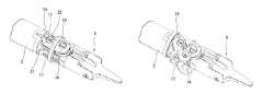
- FIG. 2is a perspective view of the configuration of one part of the surgical instrument.
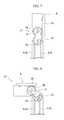
- FIG. 3is an explanatory view of the configuration of one part of the surgical instrument.
- FIG. 4is an explanatory view of the configuration of one part of the surgical instrument.
- FIG. 5is an explanatory view of the configuration of one part of the surgical instrument.
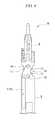
- FIG. 6is an exploded perspective view of the configuration of a treatment part of the surgical instrument.
- FIG. 7is an explanatory view of a bend operation of a treatment part of the surgical instrument.
- FIG. 8is an explanatory view of a bend operation of a treatment part of the surgical instrument.
- FIG. 9is an explanatory view of a bend operation of a treatment part of the surgical instrument.
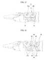
- FIG. 10is an explanatory perspective view of an operation of attaching and detaching a treatment part provided to the surgical instrument.
- FIG. 11is an explanatory perspective view of an operation of attaching and detaching a treatment part provided to the surgical instrument.
- FIG. 12is an explanatory perspective view of an operation of attaching and detaching a treatment part provided to the surgical instrument.
- FIG. 13is an explanatory perspective view of an operation of attaching and detaching a treatment part provided to the surgical instrument.
- FIG. 14is an explanatory perspective view of an operation of attaching and detaching a treatment part provided to the surgical instrument.
- FIG. 15is a perspective view of the configuration of a modified example of the embodiment.
- FIG. 16is an explanatory perspective view of an effect of the modified example.
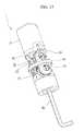
- FIG. 17is a perspective view of the configuration of another modified example of the embodiment.
- FIG. 18is a cross-sectional view of the configuration of the modified example.
- FIG. 1is an overall view of a medical manipulator including a surgical instrument of the embodiment.
- FIG. 2is a perspective view of the configuration of one part of the surgical instrument.
- FIGS. 3 to 5are explanatory views of the configuration of one part of the surgical instrument.
- FIG. 6is an exploded perspective view of the configuration of a treatment part on the surgical instrument.
- FIGS. 7 to 9are explanatory views of a bend operation of a treatment part on the surgical instrument.
- FIGS. 3 to 5 and FIGS. 7 to 9are explanatory schematic views of the configuration of the embodiment, and in some cases do not accurately depict the shapes of the members.
- the surgical instrument 1is attached to the medical manipulator 100 as one part thereof.
- the medical manipulator 100includes a master manipulator 101 , a control device 110 , and a slave manipulator 120 .
- the master manipulator 101functions as a master for transmitting the movements of the operations performed by the surgeon to the slave manipulator 120 , and includes a master display unit 102 such as a liquid crystal display device, and an operation unit 103 which the surgeon grasps and operates. Operations performed to the operation unit 103 of the master manipulator 101 are input to the control device 110 .
- the control device 110includes a master-side control device 111 that receives the input from the master manipulator 101 , and a slave-side control device 112 that outputs a drive signal to the slave manipulator 120 .
- the master-side control device 111Based on the input from the master manipulator 101 , the master-side control device 111 generates an operating command for operating the slave manipulator 120 , and outputs it to the slave-side control device 112 .
- the slave-side control device 112Based on the operating command from the master-side control device 111 , the slave-side control device 112 generates a drive signal for driving the slave manipulator 120 , and outputs it to the slave manipulator 120 .
- the slave manipulator 120includes a slave arm 121 that operates in compliance with the drive signal from the slave-side control device 112 .
- the surgical instrument 1 of this embodimentis attached to this slave arm 121 .
- a treatment instrument for performing surgery, an endoscope, and such like,can be attached to the slave manipulator 120 .
- the surgical instrument 1is a medical instrument for performing treatment to a treatment target portion. As shown in FIGS. 1 and 2 , the surgical instrument 1 includes an elongated member 2 , a treatment part 6 , a connection part 10 , and a drive control unit 45 .
- the side of the surgical instrument 1 including the treatment part 6will be referred to as the distal side, and the side of the surgical instrument 1 including the drive control unit 45 will be referred to as the proximal side.
- the elongated member 2is a cylindrical member with a long axis.
- the elongated member 2may be flexible or rigid depending on the configuration of the slave arm 121 that it is attached to. In the embodiment, the elongated member 2 is rigid.
- a connecting rod 3(moving member) for moving the treatment part 6 is disposed inside the elongated member 2 .
- the connecting rod 3includes a rod for bending 4 , one end of which is connected to a double joint for bending 11 described below and another end of which is connected to the drive control unit 45 , and a rod for opening-closing 5 , one end of which is connected to a joint for opening-closing 27 described below and another end of which is connected to the drive control unit 45 .
- the treatment part 6is provided for treating the treatment target portion.
- the treatment part 6is a forceps including a pair of forceps pieces 7 a and 7 b capable of opening and closing, and a cover 8 that holds the forceps pieces 7 a and 7 b .
- the pair of forceps pieces 7 a and 7 bare connected to each other by a shaft-shaped member 9 that forms their turning axis.
- connection part 10connects the elongated member 2 and the treatment part 6 .
- the connection part 10includes a double joint for bending 11 for bending the treatment part 6 with respect to the elongated member 2 , and a joint for opening-closing 27 (joint for operating treatment tool piece) for opening and closing the forceps pieces 7 a and 7 b.
- the double joint for bending 11includes a first fitting-cogs part 12 (first rolling guide part) fixed to the distal end of the elongated member 2 , a first turning axis part 13 connected to the distal end of the elongated member 2 , a second turning axis part 14 that extends parallel with the first turning axis part 13 and is connected to the treatment part 6 , a second fitting-cogs part 15 (rolling guide part; second rolling guide part) fixed to the treatment part 6 , and an engaging part 16 that switches the connecting state of the treatment part 6 and the elongated member 2 .
- the first fitting-cogs part 12has gear-like dent provided in a circle around (circular-arc-shaped part) the center of turning of the first turning axis part 13 .
- the second fitting-cogs part 15has gear-like dent provided in a circle around (circular-arc-shaped part) the center of turning of the second turning axis part 14 , and interlocks with the first fitting-cogs part 12 .
- the cogs of the first fitting-cogs part 12 and the second fitting-cogs part 15are provided in circles of equal radii, so that their relationship is set at a ratio of 1:1.
- the second fitting-cogs part 15can rotate while moving along the circumference of the first fitting-cogs part 12 .
- plate-like membersthat move relatively with contact between their outer peripheral parts due to friction may be provided instead of the first fitting-cogs part 12 and the second fitting-cogs part 15 .
- the configurationis one where the first fitting-cogs part 12 and the second fitting-cogs part 15 are brought into frictional contact through the interlocking of cogs
- the configurationneed not be limited to this.
- the configurationcan be a mechanism that enables two rotating bodies to rotate and roll smoothly, such as one where two rubber rollers with no interlocking cogs (and large friction) are brought into frictional contact.
- the first turning axis part 13 and the second turning axis part 14are parallel with each other and have centers of turning that extend orthogonal to the extension line of the long axis of the elongated member 2 .
- the engaging part 16includes a main unit 17 , a ring-shaped member 19 , and a locking member 21 .
- the main unit 17maintains a constant distance between the first fitting-cogs part 12 and the second fitting-cogs part 15 .
- the rod for bending 4 of the connecting rod 3is connected to the main unit 17 .
- the main unit 17turns around the first turning axis part 13 .
- the second turning axis part 14swings around the first turning axis part 13 .
- the main unit 17is connected to the first turning axis part 13 such that it can turn relative thereto and cannot be disconnected.
- the main unit 17can engage with the second turning axis part 14 such that the treatment part 6 reaches a predetermined attachment direction with respect to the main unit 17 , and can be attached and detached to/from the second turning axis part 14 .
- the main unit 17is provided with a guide 18 for limiting the movement direction of the ring-shaped member 19 .
- the guide 18has a groove formed in the outer face of the main unit 17 and extending in one direction.
- a protrusion 20is formed on the ring-shaped member 19 and fits into the groove that forms the guide 18 .
- the ring-shaped member 19thus moves along the groove.
- the ring-shaped member 19is provided separately from the main unit 17 , and binds it and the second turning axis part 14 . That is, one part of the main unit 17 and one part of the second turning axis part 14 are inserted into the ring-shaped member 19 , and the ring-shaped member 19 binds the main unit 17 and the second turning axis part 14 together.
- the protrusion 20is provided on the ring-shaped member 19 , and fits into the groove (guide 18 ) formed in the main unit 17 .
- the treatment part 6When the ring-shaped member 19 is arranged in a position where it binds the main unit 17 and the second turning axis part 14 , the treatment part 6 is in a state of being connected to the elongated member 2 (hereinafter ‘bound state’). When the ring-shaped member 19 is arranged in a position deviated from the position where it binds the main unit 17 and the second turning axis part 14 , the treatment part 6 is in a state where it can be detached from the elongated member 2 (hereinafter ‘released state’).
- the locking member 21is provided for switching between the bound state and the released state.
- the locking member 21includes a groove 22 that can communicate with the groove (guide 18 ) formed in the main unit 17 .
- the groove 22 formed in the locking member 21has the function of limiting the movement direction of the ring-shaped member 19 .
- the locking member 21can turn around the center of turning of the first turning axis part 13 .
- a rotational force around the center of turning of the first turning axis partequal to or greater than a predetermined level has acted as an external force against the locking member 21
- the locking member 21can turn around the center of turning of the first turning axis part 13 relative to the main unit 17 . That is, by rotating the locking member 21 , an operator can rotate the locking member 21 relative to the main unit 17 , and switch the communicating state between the groove 22 formed in the locking member 21 and the guide 18 formed in the main unit 17 . In a state where the abovementioned external force for rotating the locking member 21 is not being applied, the locking member 21 integrally operates the main unit 17 .
- the ring-shaped member 19can move freely along the groove 22 formed in the locking member 21 and the guide 18 formed in the main unit 17 .
- the ring-shaped member 19cannot enter the groove 22 formed in the locking member 21 . Therefore, when the groove 22 formed in the locking member 21 and the guide 18 formed in the main unit 17 are in the non-communicating state in the bound state mentioned above, the treatment part 6 is held in the bound state with respect to the elongated member 2 .
- the joint for opening-closing 27includes a first gear for opening-closing 23 (first rolling guide part; first operation turning member) that is connected to the rod for opening-closing 5 and turns coaxially with the first turning axis part 13 , a second gear for opening-closing 24 (rolling guide part; second rolling guide part; second operation turning member) that interlocks with the first gear for opening-closing 23 and turns coaxially with the second turning axis part 14 , a rack 25 connected to the second gear for opening-closing 24 , a link element 26 a that connects the rack 25 to the forceps piece 7 a , and a link element 26 b that connects the rack 25 to the forceps piece 7 b.
- first gear for opening-closing 23first rolling guide part; first operation turning member
- second gear for opening-closing 24rolling guide part; second rolling guide part; second operation turning member
- the configurationneed not be limited to this.
- the configurationmay be a mechanism that enables two rotating bodies to rotate and roll smoothly, such as one where two rubber rollers with no interlocking cogs (and large friction) are brought into frictional contact.
- the link elements 26 a and 26 b shown in FIG. 6transmit a pulling force, which comes from the rod for opening-closing 5 via first gear for opening-closing 23 and the second gear for opening-closing 24 shown in FIG. 7 , through the rack 25 .
- the link elements 26 a and 26 bconvert the advancing-retracting operation of the rack 25 to an opening-closing operation of the forceps pieces 7 a and 7 b.
- the link element 25 of the joint for opening-closing 27constitutes a toggle mechanism, with the grasping force of the forceps pieces 7 a and 7 b increasing exponentially as they move in the closing direction.
- the drive control unit 45 shown in FIG. 1includes an actuator 46 that advances and retracts the connecting rod 3 (rod for bending 4 and rod for opening-closing 5 ) in the long-axis direction of the elongated member 2 , and a detection unit 47 that detects the amount of movement of the actuator 46 .
- the drive control unit 45operates in compliance with a drive signal output from the slave-side control device 112 .
- the detection unit 47detects the amount of movement of the actuator 46 and outputs to the slave-side control device 112 .
- the movement of the actuator 46 of the drive control unit 45is feedback-controlled.
- the surgical instrument 1is used in the state where the treatment part 6 and the elongated member 2 are connected at the double joint for bending 11 and the joint for opening-closing 27 . It is also possible to detach the treatment part 6 from the elongated member 2 , and to attach another treatment part 6 to the elongated member 2 . For example, treatment can be performed while switching among different types of treatment parts 6 , and a treatment part 6 that has suffered an operational malfunction or the like can be replaced with a new treatment part 6 so that treatment can be continued.
- the double joint for bending 11can be operated by using the actuator 46 to advance and retract the rod for bending 4 .
- the joint for opening-closing 27can be operated independently from the double joint for bending 11 by using the actuator 46 to advance and retract the rod for opening-closing 5 .
- the second turning axis part 14turns around the first turning axis part 13 .
- the second fitting-cogs part 15is interlocked with the first fitting-cogs part 12 provided on the double joint for bending 11 .
- the second fitting-cogs part 15turns around the second turning axis part 14 .
- the direction of the pair of forceps pieces 7 a and 7 b on the treatment part 6changes.
- the pair of forceps pieces 7 a and 7 bdo not open or close at this time.
- the main unit 17is moved at an angle corresponding to the ratio between the radius of the first fitting-cogs part 12 and the radius of the second fitting-cogs part 15 .
- r 1is the radius of the first fitting-cogs part 12
- r 2is the radius of the second fitting-cogs part 15
- ⁇is the rotation angle of the main unit 17
- ⁇is the rotation angle of the treatment part 6
- FIGS. 10 to 14are explanatory perspective views of an operation of attaching and detaching the treatment part 6 .
- the locking member 21When it becomes necessary to detach the treatment part 6 from the elongated member 2 , the locking member 21 is rotated relative to the main unit 17 , whereby the groove 22 formed in the locking member 21 and the guide 18 formed in the main unit 17 are changed from the non-communicating state (see FIG. 10 ) to the communicating state (see FIG. 11 ).
- Thishas an effect of, for example, making it easier to insert a flat-blade screwdriver into the groove 22 formed in the locking member 21 and rotating the locking member 21 .
- the ring-shaped member 19can move along the groove 22 in the locking member 21 from the second turning axis part 14 side to the first turning axis part 13 side.
- the second turning axis part 14 and the main unit 17are unbound, and, as shown in FIGS. 13 and 14 , the second turning axis part 14 and the treatment part 6 connected to the second turning axis part 14 are detached from the main unit 17 .
- the treatment part 6can be detached from the elongated member 2 .
- Another treatment part 6can then be attached, or the detached treatment part 6 can be cleaned before re-attaching it.
- the treatment part 6When attaching the treatment part 6 to the elongated member 2 , the treatment part 6 is positioned such that the first fitting-cogs part 12 interlocks with the second fitting-cogs part 15 and the first gear for opening-closing 23 interlocks with the second gear for opening-closing 24 , the second turning axis part 14 is made to engage with the main unit 17 , and the ring-shaped member 19 is used to bind the second turning axis part 14 and the main unit 17 together. Thereafter, the locking member 21 is rotated with respect to the main unit 17 so that the groove 22 formed in the locking member 21 and the guide 18 formed in the main unit 17 are in the non-communicating state.
- a medical manipulatoris washed and disinfected each time surgery is performed.
- the treatment partcan be made detachable from the slave manipulator, and maintenance such as washing and disinfection is therefore easy.
- the treatment part of the medical manipulator described in Japanese Unexamined Patent Application, First Publication No. 2001-277157has a complex structure, and cannot be said to be easier to wash.
- the treatment part 6can be made detachable from the elongated member 2 with a simple configuration.
- the increase in the number of components for attaching and detaching the treatment part 6is less than that of the art described in surgical instrument 1 .
- the treatment part 6is made detachable from the elongated member 2 by attaching and detaching the first turning axis part 13 to and from the second turning axis part 14 , the components of the joint section for changing the direction of the treatment part 6 with respect to the elongated member 2 can be for making the treatment part 6 detachable. Therefore, in the surgical instrument 1 and the medical manipulator 100 of the embodiment, the number of components is not considerably greater than a configuration where the treatment part 6 is not detachable.
- FIG. 15is a perspective view of the configuration of the modified example.
- FIG. 16is an explanatory perspective view of the effects of the modified example.
- the main unit 17can be divided into distal members 17 A and proximal members 17 B.
- claw parts 48 for engaging with the distal members 17 Aare formed on the distal members 17 A.
- Recessed parts 49 for fitting the claw parts 48 thereinare formed in the proximal members 17 B.
- the claw parts 48 and the recessed parts 49constitute an engaging part 16 that brings the first turning axis part 13 and the treatment part 6 into an engaged state, in the same manner as the engaging part 16 described in the embodiment above.
- the modified examplehas fewer components than the embodiment described above.
- the example of an operation of a treatment tool pieceis one of opening and closing a pair of treatment tool pieces, namely the forceps pieces 7 a and 7 b
- the configurationis not limited to that.
- the operationcan be one which is bending (turning) a single treatment tool piece.
- the treatment tool piececan be a medical instrument other than forceps pieces.
- FIG. 17is a perspective view of the configuration of the modified example.
- FIG. 18is an explanatory cross-sectional view of the configuration of the modified example.
- the modified exampleincludes a treatment part 6 having an electric scalpel electrode 50 .
- the elongated member 2includes a lead wire 51 that is electrically connected to the electric scalpel electrode 50 .
- the lead wire 51 and the electrode 50are detachably connected via a plug 52 .
- the treatment part 6 of the modified exampleneed not be connected to the joint for opening-closing 27 , and need not include the joint for opening-closing 27 . Also, in the modified example, the joint for opening-closing 27 and the rod for opening-closing 5 need not be provided.
Landscapes
- Health & Medical Sciences (AREA)
- Engineering & Computer Science (AREA)
- Life Sciences & Earth Sciences (AREA)
- Surgery (AREA)
- Public Health (AREA)
- Medical Informatics (AREA)
- Veterinary Medicine (AREA)
- General Health & Medical Sciences (AREA)
- Animal Behavior & Ethology (AREA)
- Molecular Biology (AREA)
- Biomedical Technology (AREA)
- Heart & Thoracic Surgery (AREA)
- Nuclear Medicine, Radiotherapy & Molecular Imaging (AREA)
- Robotics (AREA)
- Physics & Mathematics (AREA)
- Theoretical Computer Science (AREA)
- General Engineering & Computer Science (AREA)
- Ophthalmology & Optometry (AREA)
- Human Computer Interaction (AREA)
- General Physics & Mathematics (AREA)
- Mechanical Engineering (AREA)
- Plasma & Fusion (AREA)
- Otolaryngology (AREA)
- Orthopedic Medicine & Surgery (AREA)
- Surgical Instruments (AREA)
- Manipulator (AREA)
Abstract
Description
Priority is claimed on U.S. Provisional Patent Application No. 61/515,203 filed Aug. 4, 2011, the content of which is incorporated herein by reference.
1. Field of the Invention
The present invention relates to a surgical instrument and a medical manipulator.
2. Description of Related Art
A conventionally known medical manipulator is a master-slave type medical manipulator including a master manipulator operated by an operator and a slave manipulator that operates on the basis of signals sent from the master manipulator. A surgical instrument has a treatment part for treating a treatment target portion by remote-control operation, and is attached to the medical manipulator.
For example, Japanese Unexamined Patent Application, First Publication No. 2001-277157 discloses a medical manipulator that enables a plurality of treatment parts appropriate for treatment to be switchingly attached to the arm of one slave manipulator.
According to a first aspect of the present invention, a surgical instrument for performing treatment to a treatment target portion includes: a cylindrical elongated member with a long axis, a treatment part connected to the elongated member, and a connection part that detachably connects the elongated member to the treatment part. The connection part includes a first turning axis part provided to the elongated member, a second turning axis part provided to the treatment part, a first rolling guide part that is provided to the elongated member and includes a circular-arc-shaped part coaxial with the first turning axis part, a second rolling guide part that is provided to the treatment part and includes a rolling guide part having a circular-arc-shaped part coaxial with the second turning axis part, the rolling guide part rollingly contacting the first rolling guide part, and an engaging part that brings the treatment part and the elongated member into an engaging state. The connection part is detachable between the first turning axis part and the second turning axis part.
The engaging part may include a main unit that is connected to the first turning axis part and is capable of engaging with the second turning axis part, a ring-shaped member that is provided separately from the main unit, and binds the main unit together with the second turning axis part, and a locking member that switches between a bound state and a released state, wherein in the bound state, the ring-shaped member is arranged in a position where it binds the main unit and the second turning axis part, and in the released state, the ring-shaped member is arranged in a position deviated from the position where it binds the main unit and the second turning axis part.
The main unit may include a groove that engages with the ring-shaped member and defines its movement direction. The locking member may include a groove and is capable of moving relative to the main unit. When the groove provided in the ring-shaped member and the groove provided in the main unit are in a communicating state, the locking member is capable of switching between the bound state and the released state. When the groove provided in the locking member and the groove provided in the main unit are in a non-communicating state, the treatment part is held in the bound state with respect to the elongated member.
The surgical instrument of the above aspect may further include: a treatment tool piece provided on the treatment part and is capable of operating, a joint for operating treatment tool piece that connects the elongated member to the treatment tool piece, and a moving member that is connected to the joint for operating treatment tool piece in order to operate the treatment tool piece. The joint for operating treatment tool piece may include a first operation turning member that is connected to the moving member and turns around a predetermined center of turning, a second operation turning member that is connected to the first operation turning member such that it turns in the opposite direction relative to the first operation turning member coaxial with the second turning axis part or around a center of turning that is nearer to the first turning axis part than the second turning axis part, and a link that converts the rotational force of the second operation turning member to an operation of the treatment tool piece. The joint for operating treatment tool piece is detachable between the first operation turning member and the second operation turning member by being detachable from the connection part.
The surgical instrument may include a pair of the treatment tool pieces, the operation of the treatment tool pieces being an operation of opening and closing them.
According to a second aspect of the present invention, a medical manipulator includes: the surgical instrument described above, a slave manipulator including at least one joint, the surgical instrument being attached to the slave manipulator, and a master manipulator that sends operating commands for driving the joint of the slave manipulator.
Asurgical instrument 1 and amedical manipulator 100 according to one embodiment of the present invention will be explained.FIG. 1 is an overall view of a medical manipulator including a surgical instrument of the embodiment.FIG. 2 is a perspective view of the configuration of one part of the surgical instrument.FIGS. 3 to 5 are explanatory views of the configuration of one part of the surgical instrument.FIG. 6 is an exploded perspective view of the configuration of a treatment part on the surgical instrument.FIGS. 7 to 9 are explanatory views of a bend operation of a treatment part on the surgical instrument.FIGS. 3 to 5 andFIGS. 7 to 9 are explanatory schematic views of the configuration of the embodiment, and in some cases do not accurately depict the shapes of the members.
Thesurgical instrument 1 is attached to themedical manipulator 100 as one part thereof.
Firstly, the configuration of themedical manipulator 100 of the embodiment will be explained. As shown inFIG. 1 , themedical manipulator 100 includes amaster manipulator 101, acontrol device 110, and aslave manipulator 120.
Themaster manipulator 101 functions as a master for transmitting the movements of the operations performed by the surgeon to theslave manipulator 120, and includes amaster display unit 102 such as a liquid crystal display device, and anoperation unit 103 which the surgeon grasps and operates. Operations performed to theoperation unit 103 of themaster manipulator 101 are input to thecontrol device 110.
Thecontrol device 110 includes a master-side control device 111 that receives the input from themaster manipulator 101, and a slave-side control device 112 that outputs a drive signal to theslave manipulator 120.
Based on the input from themaster manipulator 101, the master-side control device 111 generates an operating command for operating theslave manipulator 120, and outputs it to the slave-side control device 112.
Based on the operating command from the master-side control device 111, the slave-side control device 112 generates a drive signal for driving theslave manipulator 120, and outputs it to theslave manipulator 120.
Theslave manipulator 120 includes aslave arm 121 that operates in compliance with the drive signal from the slave-side control device 112. Thesurgical instrument 1 of this embodiment is attached to thisslave arm 121. In addition to thesurgical instrument 1 of this embodiment, a treatment instrument for performing surgery, an endoscope, and such like, can be attached to theslave manipulator 120.
Subsequently, the configuration of thesurgical instrument 1 will be explained.
Thesurgical instrument 1 is a medical instrument for performing treatment to a treatment target portion. As shown inFIGS. 1 and 2 , thesurgical instrument 1 includes anelongated member 2, atreatment part 6, aconnection part 10, and adrive control unit 45.
In the explanation hereinafter, the side of thesurgical instrument 1 including thetreatment part 6 will be referred to as the distal side, and the side of thesurgical instrument 1 including thedrive control unit 45 will be referred to as the proximal side.
Theelongated member 2 is a cylindrical member with a long axis. Theelongated member 2 may be flexible or rigid depending on the configuration of theslave arm 121 that it is attached to. In the embodiment, theelongated member 2 is rigid.
As shown inFIGS. 3 and 7 , a connecting rod3 (moving member) for moving thetreatment part 6 is disposed inside theelongated member 2. The connectingrod 3 includes a rod for bending4, one end of which is connected to a double joint for bending11 described below and another end of which is connected to thedrive control unit 45, and a rod for opening-closing5, one end of which is connected to a joint for opening-closing27 described below and another end of which is connected to thedrive control unit 45.
Thetreatment part 6 is provided for treating the treatment target portion. In the embodiment, as shown inFIGS. 2 and 6 , thetreatment part 6 is a forceps including a pair offorceps pieces cover 8 that holds theforceps pieces forceps pieces
Theconnection part 10 connects theelongated member 2 and thetreatment part 6. Theconnection part 10 includes a double joint for bending11 for bending thetreatment part 6 with respect to theelongated member 2, and a joint for opening-closing27 (joint for operating treatment tool piece) for opening and closing theforceps pieces
The double joint for bending11 includes a first fitting-cogs part12 (first rolling guide part) fixed to the distal end of theelongated member 2, a firstturning axis part 13 connected to the distal end of theelongated member 2, a secondturning axis part 14 that extends parallel with the firstturning axis part 13 and is connected to thetreatment part 6, a second fitting-cogs part15 (rolling guide part; second rolling guide part) fixed to thetreatment part 6, and anengaging part 16 that switches the connecting state of thetreatment part 6 and theelongated member 2.
The first fitting-cogs part 12 has gear-like dent provided in a circle around (circular-arc-shaped part) the center of turning of the firstturning axis part 13. The second fitting-cogs part 15 has gear-like dent provided in a circle around (circular-arc-shaped part) the center of turning of the secondturning axis part 14, and interlocks with the first fitting-cogs part 12. The cogs of the first fitting-cogs part 12 and the second fitting-cogs part 15 are provided in circles of equal radii, so that their relationship is set at a ratio of 1:1.
The second fitting-cogs part 15 can rotate while moving along the circumference of the first fitting-cogs part 12. Incidentally, plate-like members that move relatively with contact between their outer peripheral parts due to friction may be provided instead of the first fitting-cogs part 12 and the second fitting-cogs part 15.
While in the embodiment, the configuration is one where the first fitting-cogs part 12 and the second fitting-cogs part 15 are brought into frictional contact through the interlocking of cogs, the configuration need not be limited to this. For example, instead of frictional contact through interlocking of cogs, the configuration can be a mechanism that enables two rotating bodies to rotate and roll smoothly, such as one where two rubber rollers with no interlocking cogs (and large friction) are brought into frictional contact.
The firstturning axis part 13 and the secondturning axis part 14 are parallel with each other and have centers of turning that extend orthogonal to the extension line of the long axis of theelongated member 2.
As shown inFIG. 2 , the engagingpart 16 includes amain unit 17, a ring-shapedmember 19, and a lockingmember 21.
Themain unit 17 maintains a constant distance between the first fitting-cogs part 12 and the second fitting-cogs part 15. The rod for bending4 of the connectingrod 3 is connected to themain unit 17. When the rod for bending4 is advanced and retracted in the long-axis direction of theelongated member 2, themain unit 17 turns around the firstturning axis part 13. As a result, the secondturning axis part 14 swings around the firstturning axis part 13.
Themain unit 17 is connected to the firstturning axis part 13 such that it can turn relative thereto and cannot be disconnected.
Moreover, themain unit 17 can engage with the secondturning axis part 14 such that thetreatment part 6 reaches a predetermined attachment direction with respect to themain unit 17, and can be attached and detached to/from the secondturning axis part 14.
Themain unit 17 is provided with aguide 18 for limiting the movement direction of the ring-shapedmember 19. In the embodiment, theguide 18 has a groove formed in the outer face of themain unit 17 and extending in one direction. Aprotrusion 20 is formed on the ring-shapedmember 19 and fits into the groove that forms theguide 18. The ring-shapedmember 19 thus moves along the groove.
The ring-shapedmember 19 is provided separately from themain unit 17, and binds it and the secondturning axis part 14. That is, one part of themain unit 17 and one part of the secondturning axis part 14 are inserted into the ring-shapedmember 19, and the ring-shapedmember 19 binds themain unit 17 and the secondturning axis part 14 together. Theprotrusion 20 is provided on the ring-shapedmember 19, and fits into the groove (guide18) formed in themain unit 17.
When the ring-shapedmember 19 is arranged in a position where it binds themain unit 17 and the secondturning axis part 14, thetreatment part 6 is in a state of being connected to the elongated member2 (hereinafter ‘bound state’). When the ring-shapedmember 19 is arranged in a position deviated from the position where it binds themain unit 17 and the secondturning axis part 14, thetreatment part 6 is in a state where it can be detached from the elongated member2 (hereinafter ‘released state’).
The lockingmember 21 is provided for switching between the bound state and the released state. The lockingmember 21 includes agroove 22 that can communicate with the groove (guide18) formed in themain unit 17. As one part of theguide 18 formed in themain unit 17, thegroove 22 formed in the lockingmember 21 has the function of limiting the movement direction of the ring-shapedmember 19.
The lockingmember 21 can turn around the center of turning of the firstturning axis part 13. When a rotational force around the center of turning of the first turning axis part equal to or greater than a predetermined level has acted as an external force against the lockingmember 21, the lockingmember 21 can turn around the center of turning of the firstturning axis part 13 relative to themain unit 17. That is, by rotating the lockingmember 21, an operator can rotate the lockingmember 21 relative to themain unit 17, and switch the communicating state between thegroove 22 formed in the lockingmember 21 and theguide 18 formed in themain unit 17. In a state where the abovementioned external force for rotating the lockingmember 21 is not being applied, the lockingmember 21 integrally operates themain unit 17.
When thegroove 22 formed in the lockingmember 21 and theguide 18 formed in themain unit 17 are in the communicating state, the ring-shapedmember 19 can move freely along thegroove 22 formed in the lockingmember 21 and theguide 18 formed in themain unit 17. When thegroove 22 formed in the lockingmember 21 and theguide 18 formed in themain unit 17 are in a non-communicating state, the ring-shapedmember 19 cannot enter thegroove 22 formed in the lockingmember 21. Therefore, when thegroove 22 formed in the lockingmember 21 and theguide 18 formed in themain unit 17 are in the non-communicating state in the bound state mentioned above, thetreatment part 6 is held in the bound state with respect to theelongated member 2.
As shown inFIGS. 6 to 9 , the joint for opening-closing27 includes a first gear for opening-closing23 (first rolling guide part; first operation turning member) that is connected to the rod for opening-closing5 and turns coaxially with the firstturning axis part 13, a second gear for opening-closing24 (rolling guide part; second rolling guide part; second operation turning member) that interlocks with the first gear for opening-closing23 and turns coaxially with the secondturning axis part 14, arack 25 connected to the second gear for opening-closing24, alink element 26athat connects therack 25 to theforceps piece 7a, and alink element 26bthat connects therack 25 to theforceps piece 7b.
While in the embodiment, the first gear for opening-closing23 and the second gear for opening-closing24 are brought into frictional contact through the interlocking of cogs, the configuration need not be limited to this. For example, instead of frictional contact through interlocking of cogs, the configuration may be a mechanism that enables two rotating bodies to rotate and roll smoothly, such as one where two rubber rollers with no interlocking cogs (and large friction) are brought into frictional contact.
Thelink elements FIG. 6 transmit a pulling force, which comes from the rod for opening-closing5 via first gear for opening-closing23 and the second gear for opening-closing24 shown inFIG. 7 , through therack 25. Thelink elements rack 25 to an opening-closing operation of theforceps pieces
In the embodiment, thelink element 25 of the joint for opening-closing27 constitutes a toggle mechanism, with the grasping force of theforceps pieces
Thedrive control unit 45 shown inFIG. 1 includes anactuator 46 that advances and retracts the connecting rod3 (rod for bending4 and rod for opening-closing5) in the long-axis direction of theelongated member 2, and adetection unit 47 that detects the amount of movement of theactuator 46. Thedrive control unit 45 operates in compliance with a drive signal output from the slave-side control device 112. Thedetection unit 47 detects the amount of movement of theactuator 46 and outputs to the slave-side control device 112. Thus the movement of theactuator 46 of thedrive control unit 45 is feedback-controlled.
Subsequently, the effects of thesurgical instrument 1 and themedical manipulator 100 of this embodiment will be explained, focusing on the operating principles and effects of thesurgical instrument 1.
Thesurgical instrument 1 is used in the state where thetreatment part 6 and theelongated member 2 are connected at the double joint for bending11 and the joint for opening-closing 27. It is also possible to detach thetreatment part 6 from theelongated member 2, and to attach anothertreatment part 6 to theelongated member 2. For example, treatment can be performed while switching among different types oftreatment parts 6, and atreatment part 6 that has suffered an operational malfunction or the like can be replaced with anew treatment part 6 so that treatment can be continued.
The effects when using thesurgical instrument 1 will be explained.
The double joint for bending11 can be operated by using theactuator 46 to advance and retract the rod for bending4. The joint for opening-closing27 can be operated independently from the double joint for bending11 by using theactuator 46 to advance and retract the rod for opening-closing 5.
The effects of the double joint for bending11 will be explained.
If the rod for bending4 is advanced and retracted without advancing and retracting the rod for opening-closing5, as shown inFIGS. 3 and 5 , the secondturning axis part 14 turns around the firstturning axis part 13. At this time, since the second fitting-cogs part 15 is interlocked with the first fitting-cogs part 12 provided on the double joint for bending11, the second fitting-cogs part 15 turns around the secondturning axis part 14. As the secondturning axis part 14 swings around the firstturning axis part 13 and the second fitting-cogs part 15 turns around the secondturning axis part 14, the direction of the pair offorceps pieces treatment part 6 changes. The pair offorceps pieces
In this case, at the double joint for bending11, themain unit 17 is moved at an angle corresponding to the ratio between the radius of the first fitting-cogs part 12 and the radius of the second fitting-cogs part 15.
For example, when r1 is the radius of the first fitting-cogs part 12, r2 is the radius of the second fitting-cogs part 15, φ is the rotation angle of themain unit 17, and φ is the rotation angle of thetreatment part 6, then
r2(φ−θ)=r10 (1)
φ={(r1+r2)/r2}θ (2)
r2(φ−θ)=r10 (1)
φ={(r1+r2)/r2}θ (2)
For example, when the ratio between radius r1 of the first fitting-cogs part 12 and the radius r2 of the second fitting-cogs part 15 is 1:1 (r1=r2) as it is in this embodiment, this gives:
θ=2θ.
θ=2θ.
Therefore, when themain unit 17 is moved 45-degrees around the firstturning axis part 13, the second fitting-cogs part 15 provided on thetreatment part 6 side tilts 90-degrees with regard to the first fitting-cogs part 12. That is, this is an acceleration mechanism that makes it possible to reduce the amount of angular movement of themain unit 17 with respect to the amount of angular movement of thetreatment part 6.
Subsequently, the effects when thetreatment part 6 is made detachable from theelongated member 2 will be explained.
When it becomes necessary to detach thetreatment part 6 from theelongated member 2, the lockingmember 21 is rotated relative to themain unit 17, whereby thegroove 22 formed in the lockingmember 21 and theguide 18 formed in themain unit 17 are changed from the non-communicating state (seeFIG. 10 ) to the communicating state (seeFIG. 11 ). This has an effect of, for example, making it easier to insert a flat-blade screwdriver into thegroove 22 formed in the lockingmember 21 and rotating the lockingmember 21.
When thegroove 22 formed in the lockingmember 21 and theguide 18 formed in themain unit 17 are in the communicating state, the ring-shapedmember 19 can move along thegroove 22 in the lockingmember 21 from the secondturning axis part 14 side to the firstturning axis part 13 side. As shown inFIG. 12 , when the operator moves the ring-shapedmember 19 to the firstturning axis part 13 side, the secondturning axis part 14 and themain unit 17 are unbound, and, as shown inFIGS. 13 and 14 , the secondturning axis part 14 and thetreatment part 6 connected to the secondturning axis part 14 are detached from themain unit 17.
In the embodiment, whatever the bend state of the double joint for bending11, and whatever the open-close state of the joint for opening-closing27, thetreatment part 6 can be detached from theelongated member 2.
Anothertreatment part 6 can then be attached, or thedetached treatment part 6 can be cleaned before re-attaching it.
When attaching thetreatment part 6 to theelongated member 2, thetreatment part 6 is positioned such that the first fitting-cogs part 12 interlocks with the second fitting-cogs part 15 and the first gear for opening-closing23 interlocks with the second gear for opening-closing24, the secondturning axis part 14 is made to engage with themain unit 17, and the ring-shapedmember 19 is used to bind the secondturning axis part 14 and themain unit 17 together. Thereafter, the lockingmember 21 is rotated with respect to themain unit 17 so that thegroove 22 formed in the lockingmember 21 and theguide 18 formed in themain unit 17 are in the non-communicating state.
It thus becomes possible to use thetreatment part 6 attached to theelongated member 2.
Generally, to prevent infection, a medical manipulator is washed and disinfected each time surgery is performed.
For example, in the case of the medical manipulator described in Japanese Unexamined Patent Application, First Publication No. 2001-277157, the treatment part can be made detachable from the slave manipulator, and maintenance such as washing and disinfection is therefore easy. However, since a great many components are required to realize a configuration that enables the treatment part to be made detachable, the treatment part of the medical manipulator described in Japanese Unexamined Patent Application, First Publication No. 2001-277157 has a complex structure, and cannot be said to be easier to wash.
In contrast, according to thesurgical instrument 1 and themedical manipulator 100 of this embodiment, since themain unit 17 and the secondturning axis part 14 are bound by the ring-shapedmember 19, thetreatment part 6 can be made detachable from theelongated member 2 with a simple configuration.
Also, according to thesurgical instrument 1 and themedical manipulator 100 of this embodiment, the increase in the number of components for attaching and detaching thetreatment part 6 is less than that of the art described insurgical instrument 1.
Since thetreatment part 6 is made detachable from theelongated member 2 by attaching and detaching the firstturning axis part 13 to and from the secondturning axis part 14, the components of the joint section for changing the direction of thetreatment part 6 with respect to theelongated member 2 can be for making thetreatment part 6 detachable. Therefore, in thesurgical instrument 1 and themedical manipulator 100 of the embodiment, the number of components is not considerably greater than a configuration where thetreatment part 6 is not detachable.
Subsequently, a modified example of the embodiment will be explained.FIG. 15 is a perspective view of the configuration of the modified example.FIG. 16 is an explanatory perspective view of the effects of the modified example.
As shown inFIG. 15 , in the modified example, instead of a configuration where themain unit 17 and the secondturning axis part 14 can be attached and detached, themain unit 17 can be divided intodistal members 17A andproximal members 17B.
As shown inFIGS. 15 and 16 , clawparts 48 for engaging with thedistal members 17A are formed on thedistal members 17A. Recessedparts 49 for fitting theclaw parts 48 therein are formed in theproximal members 17B. Theclaw parts 48 and the recessedparts 49 constitute anengaging part 16 that brings the firstturning axis part 13 and thetreatment part 6 into an engaged state, in the same manner as the engagingpart 16 described in the embodiment above.
When theclaw parts 48 of thedistal members 17A are pressed into the recessedparts 49 of theproximal members 17B, theproximal members 17B and thedistal members 17A elastically deform slightly, and theclaw parts 48 enter the recessedparts 49. Thetreatment part 6 is thus engaged with theelongated member 2.
This configuration achieves effects similar to those of the embodiment described above.
In addition, the modified example has fewer components than the embodiment described above.
While in the embodiment including the modified example described above, the example of an operation of a treatment tool piece is one of opening and closing a pair of treatment tool pieces, namely theforceps pieces
Subsequently, another modified example of the embodiment will be explained.FIG. 17 is a perspective view of the configuration of the modified example.FIG. 18 is an explanatory cross-sectional view of the configuration of the modified example.
As shown inFIGS. 17 and 18 , instead of thetreatment part 6 having theforceps pieces treatment part 6 having anelectric scalpel electrode 50.
Theelongated member 2 includes alead wire 51 that is electrically connected to theelectric scalpel electrode 50. Thelead wire 51 and theelectrode 50 are detachably connected via aplug 52. Thetreatment part 6 of the modified example need not be connected to the joint for opening-closing27, and need not include the joint for opening-closing 27. Also, in the modified example, the joint for opening-closing27 and the rod for opening-closing5 need not be provided.
This type of configuration achieves effects similar to those of the embodiment described above.
While an embodiment of the invention has been described in detail with reference to the drawings, the specific configuration is not limited to this embodiment.
For example, it is acceptable to use a treatment part that bends at the first turning axis part and does not include the second turning axis part described above.
Various other additions, omissions, substitutions, and other changes can be made to the configuration without deviating from the main points of the invention.
The invention is not limited to the forgoing description, and is limited only by the accompanying claims.
Claims (11)
1. A surgical instrument for performing treatment to a treatment target portion, the surgical instrument comprising:
a cylindrical elongated member having a long axis;
a treatment part connected to the elongated member; and
a connection part that detachably connects the elongated member to the treatment part, wherein
the connection part comprises:
a first turning axis part provided to the elongated member;
a second turning axis part provided to the treatment part;
a first rolling guide part that is provided to the elongated member and includes a circular-arc-shaped part coaxial with the first turning axis part;
a second rolling guide part that is provided to the treatment part and includes a rolling guide part having a circular-arc-shaped part coaxial with the second turning axis part, the rolling guide part rollingly contacting the first rolling guide part;
an engaging part that brings the treatment part and the elongated member into an engaging state, and
the connection part is detachable between the first turning axis part and the second turning axis part;
wherein the engaging part comprises:
a main unit that is connected to the first turning axis part and is capable of engaging with the second turning axis part;
a ring-shaped member that is provided separately from the main unit, and binds the main unit together with the second turning axis part; and
a locking member that switches between a bound state and a released state, wherein in the bound state, the ring-shaped member is arranged in a position where it binds the main unit and the second turning axis part, and in the released state, the ring-shaped member is arranged in a position deviated from the position where it binds the main unit and the second turning axis part.
2. The surgical instrument according toclaim 1 , wherein
the main unit is provided with a groove that engages with the ring-shaped member and defines its movement direction;
the locking member is provided with a groove and is capable of moving relative to the main unit;
when the groove provided in the locking member and the groove provided in the main unit are in a communicating state, the ring-shaped member is capable of switching between the released state and the bound state; and
when the groove provided in the locking member and the groove provided in the main unit are in a non-communicating state, the treatment part is held in the bound state with respect to the elongated member.
3. The surgical instrument according toclaim 1 , further comprising:
a treatment tool piece provided on the treatment part and is capable of operating;
a joint for operating the treatment tool piece that connects the elongated member to the treatment tool piece; and
a moving member that is connected to the joint for operating the treatment tool piece in order to operate the treatment tool piece, wherein
the joint for operating the treatment tool piece comprises:
a first operation turning member that is connected to the moving member and turns around a predetermined center of turning;
a second operation turning member that is connected to the first operation turning member such that it turns in the opposite direction relative to the first operation turning member coaxial with the second turning axis part or around a center of turning that is nearer to the first turning axis part than the second turning axis part; and
a link that converts a rotational force of the second operation turning member to an operation of the treatment tool piece;
the joint for operating treatment tool piece is detachable between the first operation turning member and the second operation turning member by being detachable from the connection part.
4. The surgical instrument according toclaim 3 , wherein
the treatment tool piece comprises a pair of treatment tool pieces, and
the operation of the treatment tool pieces is an operation of opening and closing the pair of treatment tool pieces.
5. A medical manipulator comprising:
the surgical instrument according toclaim 1 ;
a slave manipulator including at least one joint, the surgical instrument being attached to the slave manipulator; and
a master manipulator that generates operating commands for driving the joint of the slave manipulator.
6. The surgical instrument according toclaim 2 , further comprising:
a treatment tool piece provided on the treatment part and is capable of operating;
a joint for operating the treatment tool piece that connects the elongated member to the treatment tool piece; and
a moving member that is connected to the joint for operating the treatment tool piece in order to operate the treatment tool piece, wherein
the joint for operating the treatment tool piece comprises:
a first operation turning member that is connected to the moving member and turns around a predetermined center of turning;
a second operation turning member that is connected to the first operation turning member such that it turns in the opposite direction relative to the first operation turning member coaxial with the second turning axis part or around a center of turning that is nearer to the first turning axis part than the second turning axis part; and
a link that converts a rotational force of the second operation turning member to an operation of the treatment tool piece;
the joint for operating treatment tool piece is detachable between the first operation turning member and the second operation turning member by being detachable from the connection part.
7. The surgical instrument according toclaim 6 , wherein
the treatment tool piece comprises a pair of treatment tool pieces, and
the operation of the treatment tool pieces is an operation of opening and closing the pair of treatment tool pieces.
8. A medical manipulator comprising:
the surgical instrument according toclaim 1 ;
a slave manipulator including at least one joint, the surgical instrument being attached to the slave manipulator; and
a master manipulator that generates operating commands for driving the joint of the slave manipulator.
9. A medical manipulator comprising:
the surgical instrument according toclaim 2 ;
a slave manipulator including at least one joint, the surgical instrument being attached to the slave manipulator; and
a master manipulator that generates operating commands for driving the joint of the slave manipulator.
10. A medical manipulator comprising:
the surgical instrument according toclaim 3 ;
a slave manipulator including at least one joint, the surgical instrument being attached to the slave manipulator; and
a master manipulator that generates operating commands for driving the joint of the slave manipulator.
11. A medical manipulator comprising:
the surgical instrument according toclaim 4 ;
a slave manipulator including at least one joint, the surgical instrument being attached to the slave manipulator; and
a master manipulator that generates operating commands for driving the joint of the slave manipulator.
Priority Applications (1)
| Application Number | Priority Date | Filing Date | Title |
|---|---|---|---|
| US13/566,023US9161772B2 (en) | 2011-08-04 | 2012-08-03 | Surgical instrument and medical manipulator |
Applications Claiming Priority (3)
| Application Number | Priority Date | Filing Date | Title |
|---|---|---|---|
| US201161515203P | 2011-08-04 | 2011-08-04 | |
| PCT/JP2012/069868WO2013018897A1 (en) | 2011-08-04 | 2012-08-03 | Surgical implement and medical treatment manipulator |
| US13/566,023US9161772B2 (en) | 2011-08-04 | 2012-08-03 | Surgical instrument and medical manipulator |
Publications (2)
| Publication Number | Publication Date |
|---|---|
| US20130066333A1 US20130066333A1 (en) | 2013-03-14 |
| US9161772B2true US9161772B2 (en) | 2015-10-20 |
Family
ID=52581053
Family Applications (1)
| Application Number | Title | Priority Date | Filing Date |
|---|---|---|---|
| US13/566,023Active2033-07-22US9161772B2 (en) | 2011-08-04 | 2012-08-03 | Surgical instrument and medical manipulator |
Country Status (4)
| Country | Link |
|---|---|
| US (1) | US9161772B2 (en) |
| EP (1) | EP2740433B1 (en) |
| CN (1) | CN103732173B (en) |
| WO (1) | WO2013018897A1 (en) |
Cited By (13)
| Publication number | Priority date | Publication date | Assignee | Title |
|---|---|---|---|---|
| US20130263685A1 (en)* | 2010-06-10 | 2013-10-10 | Mark Doyle | Flexible wrist-type element |
| US20130269109A1 (en)* | 2007-02-02 | 2013-10-17 | Hansen Medical, Inc. | Mounting support assembly for suspending a medical instrument driver above an operating table |
| US20130304083A1 (en)* | 2012-04-18 | 2013-11-14 | Daniel Kaercher | Medical Instrument with Bendable Shaft |
| US20140222019A1 (en)* | 2011-02-17 | 2014-08-07 | Sven Brudniok | Surgical Instrument |
| USD760387S1 (en)* | 2014-03-17 | 2016-06-28 | Intuitive Surgical Operations, Inc. | Surgical instrument end portion |
| USD767129S1 (en)* | 2014-03-17 | 2016-09-20 | Intuitive Surgical Operations, Inc. | Surgical instrument end portion |
| USD767130S1 (en)* | 2014-03-17 | 2016-09-20 | Intuitive Surgical Operations, Inc. | Surgical instrument end portion |
| USD768295S1 (en)* | 2014-03-17 | 2016-10-04 | Intuitive Surgical Operations, Inc. | Surgical instrument end portion |
| USD864386S1 (en) | 2016-07-14 | 2019-10-22 | Intuitive Surgical Operations, Inc. | Surgical instrument actuator end portion |
| USD865163S1 (en) | 2016-07-14 | 2019-10-29 | Intuitive Surgical Operations, Inc. | Surgical instrument actuator end portion |
| USD865164S1 (en) | 2016-07-14 | 2019-10-29 | Intuitive Surgical Operations, Inc. | Surgical instrument actuator end portion |
| USD884892S1 (en) | 2018-04-20 | 2020-05-19 | Intuitive Surgical Operations, Inc. | Surgical instrument backend housing |
| US10898192B2 (en)* | 2017-06-15 | 2021-01-26 | Roberto Tapia Espriu | Adjustable pressure surgical clamp with releasable or integrated remote manipulator for laparoscopies |
Families Citing this family (15)
| Publication number | Priority date | Publication date | Assignee | Title |
|---|---|---|---|---|
| CN104191429B (en)* | 2014-07-28 | 2016-04-27 | 南京航空航天大学 | The mixing control method of a kind of tendon driving device hand position and tendon tension force and control device |
| EP3179952B1 (en)* | 2014-08-13 | 2019-03-20 | Covidien LP | Robotically controlled mechanical advantage gripper |
| CN107405161B (en)* | 2015-02-25 | 2020-05-26 | 奥林巴斯株式会社 | Mechanical arm |
| US10646298B2 (en) | 2015-07-31 | 2020-05-12 | Globus Medical, Inc. | Robot arm and methods of use |
| US10058394B2 (en) | 2015-07-31 | 2018-08-28 | Globus Medical, Inc. | Robot arm and methods of use |
| CN105286999B (en)* | 2015-10-15 | 2017-09-29 | 天津大学 | Minimally Invasive Surgery apparatus with end rotation function |
| EP3179441A1 (en) | 2015-12-11 | 2017-06-14 | Authentic Vision GmbH | Seal tamper detection |
| WO2018109851A1 (en) | 2016-12-14 | 2018-06-21 | オリンパス株式会社 | Medical manipulator system |
| WO2018179323A1 (en) | 2017-03-31 | 2018-10-04 | オリンパス株式会社 | Manipulator |
| US10639116B2 (en)* | 2017-10-23 | 2020-05-05 | Ethicon Llc | Distally replaceable cable systems in surgical tools |
| CN108013906A (en)* | 2017-12-01 | 2018-05-11 | 微创(上海)医疗机器人有限公司 | Snakelike operating theater instruments |
| CN110464419B (en)* | 2019-08-27 | 2020-08-11 | 张逸飞 | Clamping and guiding device for orthopedic surgery |
| EP4104790B1 (en)* | 2020-03-27 | 2024-05-01 | RIVERFIELD Inc. | Surgical tool |
| JP6890363B1 (en)* | 2021-02-02 | 2021-06-18 | 株式会社メドメタレックス | Surgical instruments |
| CN112975933B (en)* | 2021-02-08 | 2021-11-05 | 上海睿刀医疗科技有限公司 | Interlocking mechanical arm |
Citations (203)
| Publication number | Priority date | Publication date | Assignee | Title |
|---|---|---|---|---|
| JPS6329810A (en) | 1986-07-23 | 1988-02-08 | Matsushita Electric Ind Co Ltd | Arm control device |
| JPS6434688A (en) | 1987-07-29 | 1989-02-06 | Kubota Ltd | Master/slave manipulator |
| US4830569A (en)* | 1987-03-31 | 1989-05-16 | Asea Brown Boveri Ab | Industrial robot having a detachable electrical connection between housing on robot arm and tool holder |
| JPH01271185A (en) | 1988-04-20 | 1989-10-30 | Fujitsu Ltd | Remote robot manipulating system |
| JPH0271980A (en) | 1988-09-05 | 1990-03-12 | Hitachi Ltd | master slave manipulator |
| JPH02292193A (en) | 1989-04-28 | 1990-12-03 | Toshiba Corp | Operation commanding device |
| JPH03161289A (en) | 1989-11-16 | 1991-07-11 | Agency Of Ind Science & Technol | How to control master/slave robots |
| JPH0596477A (en) | 1991-10-03 | 1993-04-20 | Mitsubishi Heavy Ind Ltd | Control method for master and slave manipulators |
| US5214969A (en) | 1991-02-19 | 1993-06-01 | Philip Morris Incorporated | Automatic testing of a plurality of smoking articles |
| JPH05329784A (en) | 1992-05-28 | 1993-12-14 | Yaskawa Electric Corp | Master / slave robot control method |
| JPH071366A (en) | 1993-05-13 | 1995-01-06 | Meidensha Corp | Control device for industrial manipulator |
| JPH07194609A (en) | 1993-12-29 | 1995-08-01 | Olympus Optical Co Ltd | Master-slave medical manipulator |
| JPH07241300A (en) | 1994-03-04 | 1995-09-19 | Olympus Optical Co Ltd | Holder of medical treatment appliance |
| JPH07246578A (en) | 1994-03-11 | 1995-09-26 | Yaskawa Electric Corp | Master hand device |
| JPH0796182B2 (en) | 1988-03-16 | 1995-10-18 | ニッタ株式会社 | A device that eliminates the effects of the weight of the tool |
| EP0677278A1 (en) | 1994-04-13 | 1995-10-18 | Carl Zeiss | Stereotactic adapter and method for its use |
| JPH0866883A (en) | 1994-08-29 | 1996-03-12 | Aichi Corp | Manipulator gripper controller |
| JPH08215204A (en) | 1995-02-08 | 1996-08-27 | Olympus Optical Co Ltd | Medical manipulator |
| JPH08243080A (en) | 1995-03-07 | 1996-09-24 | Olympus Optical Co Ltd | Endoscope cleaning and disinfecting apparatus |
| US5603723A (en)* | 1995-01-11 | 1997-02-18 | United States Surgical Corporation | Surgical instrument configured to be disassembled for cleaning |
| WO1997016124A1 (en) | 1995-10-31 | 1997-05-09 | Smith & Nephew, Inc. | Surgical instrument handpiece and system |
| WO1997016123A1 (en) | 1995-10-31 | 1997-05-09 | Smith & Nephew, Inc. | Magnetic switching element for controlling a surgical device |
| US5632432A (en) | 1994-12-19 | 1997-05-27 | Ethicon Endo-Surgery, Inc. | Surgical instrument |
| US5649956A (en) | 1995-06-07 | 1997-07-22 | Sri International | System and method for releasably holding a surgical instrument |
| US5656903A (en) | 1993-10-01 | 1997-08-12 | The Ohio State University Research Foundation | Master-slave position and motion control system |
| WO1997029690A1 (en) | 1996-02-20 | 1997-08-21 | Computer Motion, Inc. | A method and apparatus for performing minimally invasive cardiac procedures |
| JPH10128538A (en) | 1996-10-29 | 1998-05-19 | Hitachi Constr Mach Co Ltd | Welding robot and its sensor adapter |
| US5762458A (en) | 1996-02-20 | 1998-06-09 | Computer Motion, Inc. | Method and apparatus for performing minimally invasive cardiac procedures |
| WO1998025666A1 (en) | 1996-12-12 | 1998-06-18 | Intuitive Surgical, Inc. | Multi-component telepresence system and method |
| US5836869A (en) | 1994-12-13 | 1998-11-17 | Olympus Optical Co., Ltd. | Image tracking endoscope system |
| JPH11300662A (en) | 1998-04-27 | 1999-11-02 | Yokogawa Electric Corp | Micro tweezers |
| US6063095A (en) | 1996-02-20 | 2000-05-16 | Computer Motion, Inc. | Method and apparatus for performing minimally invasive surgical procedures |
| WO2000051486A1 (en) | 1999-03-03 | 2000-09-08 | Computer Motion, Inc. | Method and apparatus for performing minimally invasive surgical procedures |
| WO2000060421A2 (en) | 1999-04-07 | 2000-10-12 | Intuitive Surgical, Inc. | Alignment of master and slave in a minimally invasive surgical apparatus |
| US6132441A (en) | 1996-11-22 | 2000-10-17 | Computer Motion, Inc. | Rigidly-linked articulating wrist with decoupled motion transmission |
| JP2000312684A (en) | 1999-04-30 | 2000-11-14 | Olympus Optical Co Ltd | Manipulator system for medical treatment |
| US6206903B1 (en) | 1999-10-08 | 2001-03-27 | Intuitive Surgical, Inc. | Surgical tool with mechanical advantage |
| JP2001087281A (en) | 1999-09-20 | 2001-04-03 | Olympus Optical Co Ltd | Multifunctional manipulator |
| JP2001113481A (en) | 1999-10-13 | 2001-04-24 | Natl Inst Of Advanced Industrial Science & Technology Meti | Power assist device and control method thereof |
| US6246200B1 (en) | 1998-08-04 | 2001-06-12 | Intuitive Surgical, Inc. | Manipulator positioning linkage for robotic surgery |
| US20010021859A1 (en) | 2000-02-24 | 2001-09-13 | Toshikazu Kawai | Forceps and manipulator with using thereof |
| JP2001277157A (en) | 2000-03-31 | 2001-10-09 | Toshiba Corp | Medical manipulator |
| JP2001309920A (en) | 2000-02-24 | 2001-11-06 | Hitachi Ltd | Forceps and manipulator using the same |
| US20010055062A1 (en) | 2000-04-20 | 2001-12-27 | Keiji Shioda | Operation microscope |
| JP2002014287A (en) | 2000-06-28 | 2002-01-18 | Olympus Optical Co Ltd | Microscopic instrument for surgery |
| JP2002059380A (en) | 2000-08-22 | 2002-02-26 | Olympus Optical Co Ltd | Master-slave device |
| JP2002102248A (en) | 2000-09-29 | 2002-04-09 | Toshiba Corp | manipulator |
| US20020072736A1 (en) | 1996-12-12 | 2002-06-13 | Intuitive Surgical, Inc. | Surgical robotic tools, data architecture, and use |
| US20020128552A1 (en) | 1998-11-20 | 2002-09-12 | Intuitive Surgical, Inc. | Repositioning and reorientation of master/slave relationship in minimally invasive telesurgery |
| JP2002272758A (en) | 2001-03-19 | 2002-09-24 | Hitachi Ltd | Surgery support device |
| JP2003024336A (en) | 2001-07-16 | 2003-01-28 | Hitachi Ltd | Operation instrument |
| US20030033024A1 (en) | 2001-08-10 | 2003-02-13 | Kabushiki Kaisha Toshiba | Medical manipulator and method of controlling the same |
| US20030060927A1 (en) | 2001-09-25 | 2003-03-27 | Intuitive Surgical, Inc. | Removable infinite roll master grip handle and touch sensor for robotic surgery |
| US20030069471A1 (en) | 2001-09-11 | 2003-04-10 | Olympus Optical Co., Ltd. | Medical image observation apparatus or microscopic system and method of displaying medical images |
| US6557558B1 (en) | 1999-08-31 | 2003-05-06 | Hitachi, Ltd. | Medical treatment apparatus |
| US6574355B2 (en) | 1992-01-21 | 2003-06-03 | Intuitive Surigical, Inc. | Method and apparatus for transforming coordinate systems in a telemanipulation system |
| WO2003049596A2 (en) | 2001-12-07 | 2003-06-19 | Computer Motion, Inc. | Microwrist system for surgical procedures |
| US6602185B1 (en) | 1999-02-18 | 2003-08-05 | Olympus Optical Co., Ltd. | Remote surgery support system |
| JP2003250812A (en) | 2002-02-28 | 2003-09-09 | Olympus Optical Co Ltd | Stereoscopic display device for medical treatment |
| JP2003265500A (en) | 2002-03-15 | 2003-09-24 | Hitachi Ltd | Surgery support device |
| US6645196B1 (en) | 2000-06-16 | 2003-11-11 | Intuitive Surgical, Inc. | Guided tool change |
| US20030216723A1 (en) | 2002-05-17 | 2003-11-20 | Olympus Optical Co., Ltd | Operation system and mounting device for external device for use in the operation system |
| JP2003340752A (en) | 2002-05-21 | 2003-12-02 | Toshiba Corp | Medical manipulator |
| US6676684B1 (en)* | 2001-09-04 | 2004-01-13 | Intuitive Surgical, Inc. | Roll-pitch-roll-yaw surgical tool |
| US6685698B2 (en)* | 2000-07-27 | 2004-02-03 | Intuitive Surgical, Inc. | Roll-pitch-roll surgical tool |
| US6699177B1 (en) | 1996-02-20 | 2004-03-02 | Computer Motion, Inc. | Method and apparatus for performing minimally invasive surgical procedures |
| JP2004105451A (en) | 2002-09-18 | 2004-04-08 | Toshiba Corp | Medical manipulator |
| US20040111113A1 (en)* | 2002-12-09 | 2004-06-10 | The University Of Tokyo | High-rigidity forceps tip assembly for active forceps and active forceps equipped with the same |
| US20040140787A1 (en) | 2002-10-29 | 2004-07-22 | Shusasku Okamoto | Apparatus and method for robot handling control |
| US6783524B2 (en) | 2001-04-19 | 2004-08-31 | Intuitive Surgical, Inc. | Robotic surgical tool with ultrasound cauterizing and cutting instrument |
| US20040186624A1 (en) | 2003-01-30 | 2004-09-23 | Fanuc Ltd. | Object taking-out apparatus |
| US20040243147A1 (en) | 2001-07-03 | 2004-12-02 | Lipow Kenneth I. | Surgical robot and robotic controller |
| US20050033117A1 (en) | 2003-06-02 | 2005-02-10 | Olympus Corporation | Object observation system and method of controlling object observation system |
| US20050125027A1 (en) | 2003-12-06 | 2005-06-09 | Richard Wolf Gmbh | Medical instrument |
| US6913613B2 (en)* | 1999-09-09 | 2005-07-05 | Tuebingen Scientific Surgical Products Ohg | Surgical instrument for minimally invasive surgical interventions |
| JP2005192743A (en) | 2004-01-06 | 2005-07-21 | Olympus Corp | Medical appliance retainer and retaining system |
| JP2005261827A (en) | 2004-03-22 | 2005-09-29 | Olympus Corp | Treatment tool for endoscope |
| JP2005312991A (en) | 2005-07-08 | 2005-11-10 | Olympus Corp | Medical manipulator system |
| US20050273086A1 (en) | 1995-06-07 | 2005-12-08 | Sri International | Surgical manipulator for a telerobotic system |
| JP2006061272A (en) | 2004-08-25 | 2006-03-09 | Olympus Corp | Medical instrument holding device |
| US20060052664A1 (en) | 2000-04-03 | 2006-03-09 | Julian Christopher A | Connector device for a controllable instrument |
| US20060087746A1 (en) | 2004-10-22 | 2006-04-27 | Kenneth Lipow | Remote augmented motor-sensory interface for surgery |
| US20060116973A1 (en) | 2003-06-02 | 2006-06-01 | Matsushita Electric Industrial Co., Ltd. | Article handling system and method and article management system and method |
| JP2006167867A (en) | 2004-12-16 | 2006-06-29 | Fuji Heavy Ind Ltd | Remote control device |
| US20060155262A1 (en)* | 2005-01-11 | 2006-07-13 | Kosuke Kishi | Surgical operation apparatus and manipulator for use therein |
| US20060161138A1 (en) | 1996-12-12 | 2006-07-20 | Intuitive Surgical Inc. | Sterile surgical adaptor |
| US20060190031A1 (en)* | 2005-02-18 | 2006-08-24 | Ethicon Endo-Surgery, Inc. | Surgical instrument with articulating shaft with rigid firing bar supports |
| US7101363B2 (en)* | 2002-10-02 | 2006-09-05 | Hitachi, Ltd. | Medical manipulator having a plurality of joints |
| US7107124B2 (en) | 1992-01-21 | 2006-09-12 | Sri International | Roll-pitch-roll wrist methods for minimally invasive robotic surgery |
| US20060235436A1 (en) | 1996-12-12 | 2006-10-19 | Intuitive Surgical Inc. | Sterile surgical adaptor |
| JP2006288955A (en) | 2005-04-14 | 2006-10-26 | Olympus Medical Systems Corp | Surgery system |
| JP2006321027A (en) | 2005-05-20 | 2006-11-30 | Hitachi Ltd | Master / slave manipulator system and its operation input device |
| EP1728475A2 (en) | 2005-06-03 | 2006-12-06 | Tyco Healthcare Group Lp | Surgical instruments employing sensors |
| JP2007029274A (en) | 2005-07-25 | 2007-02-08 | Hitachi Ltd | Surgical device |
| JP2007038315A (en) | 2005-08-01 | 2007-02-15 | Toyota Motor Corp | Operation device and operation control method and program therefor |
| JP2007098507A (en) | 2005-10-04 | 2007-04-19 | Nagoya Institute Of Technology | Work assistance device |
| US20070089557A1 (en) | 2004-09-30 | 2007-04-26 | Solomon Todd R | Multi-ply strap drive trains for robotic arms |
| WO2007047782A2 (en) | 2005-10-20 | 2007-04-26 | Intuitive Surgical, Inc | Auxiliary image display and manipulation on a computer display in a medical robotic system |
| US20070119274A1 (en) | 1996-12-12 | 2007-05-31 | Devengenzo Roman L | Instrument interface of a robotic surgical system |
| US20070137372A1 (en) | 2005-12-20 | 2007-06-21 | Devengenzo Roman L | Wireless communication in a robotic surgical system |
| US20070167680A1 (en) | 2006-01-13 | 2007-07-19 | Olympus Medical Systems Corp. | Medical treatment endoscope |
| US20070167679A1 (en) | 2006-01-13 | 2007-07-19 | Olympus Medical Systems Corp. | Medical treatment endoscope |
| US20070197896A1 (en) | 2005-12-09 | 2007-08-23 | Hansen Medical, Inc | Robotic catheter system and methods |
| US20070208375A1 (en)* | 2006-02-23 | 2007-09-06 | Kouji Nishizawa | Surgical device |
| US20070219668A1 (en) | 2006-03-02 | 2007-09-20 | Honda Motor Co., Ltd. | Hand control system, method, program, hand, and robot |
| US20070225550A1 (en) | 2006-03-24 | 2007-09-27 | Abhishek Gattani | System and method for 3-D tracking of surgical instrument in relation to patient body |
| JP3999816B2 (en) | 1996-05-20 | 2007-10-31 | インチュイティブ サージカル,インコーポレイテッド | Articulated surgical instrument for performing minimally invasive surgery with improved sophistication and sensitivity |
| US7295893B2 (en) | 2003-03-31 | 2007-11-13 | Kabushiki Kaisha Toshiba | Manipulator and its control apparatus and method |
| WO2007138674A1 (en) | 2006-05-30 | 2007-12-06 | Olympus Medical Systems Corp. | Endoscope treatment system |
| US7313464B1 (en) | 2006-09-05 | 2007-12-25 | Adept Technology Inc. | Bin-picking system for randomly positioned objects |
| JP2008000282A (en) | 2006-06-21 | 2008-01-10 | Olympus Medical Systems Corp | Procedure image recording control system and operation system |
| US7331967B2 (en) | 2002-09-09 | 2008-02-19 | Hansen Medical, Inc. | Surgical instrument coupling mechanism |
| JP2008036793A (en) | 2006-08-08 | 2008-02-21 | Terumo Corp | Working mechanism and manipulator |
| US20080046122A1 (en) | 2003-06-30 | 2008-02-21 | Intuitive Surgical, Inc. | Maximum torque driving of robotic surgical tools in robotic surgical systems |
| US20080051631A1 (en) | 2006-01-13 | 2008-02-28 | Olympus Medical Systems Corp. | Medical treatment endoscope |
| US20080059131A1 (en) | 2006-08-29 | 2008-03-06 | Canon Kabushiki Kaisha | Force sense presentation device, mixed reality system, information processing method, and information processing apparatus |
| WO2008038184A2 (en) | 2006-09-25 | 2008-04-03 | Koninklijke Philips Electronics N.V. | Haptic feedback medical scanning methods and systems |
| JP2008093270A (en) | 2006-10-13 | 2008-04-24 | Terumo Corp | manipulator |
| CN101167658A (en) | 2006-10-25 | 2008-04-30 | 泰尔茂株式会社 | manipulator system |
| US20080140088A1 (en) | 1996-12-12 | 2008-06-12 | Intuitive Surgical, Inc. | Disposable sterile surgical adaptor |
| US20080177285A1 (en) | 1998-02-24 | 2008-07-24 | Hansen Medical, Inc. | Surgical instrument |
| JP2008173724A (en) | 2007-01-19 | 2008-07-31 | Hitachi Ltd | Master / slave manipulator system |
| JP4129313B2 (en) | 1998-05-19 | 2008-08-06 | オリンパス株式会社 | Medical system control device |
| US20080204425A1 (en) | 2007-02-27 | 2008-08-28 | Kenichiro Nagasaka | Force/tactile display, method for controlling force/tactile display, and computer program |
| US7422592B2 (en)* | 2000-12-29 | 2008-09-09 | Intuitive Surgical, Inc. | Bipolar cauterizing instrument |
| WO2008108289A1 (en) | 2007-03-01 | 2008-09-12 | Tokyo Institute Of Technology | Maneuvering system having inner force sense presenting function |
| US20080234866A1 (en) | 2007-03-20 | 2008-09-25 | Kosuke Kishi | Master-slave manipulator system |
| US20080243142A1 (en) | 2007-02-20 | 2008-10-02 | Gildenberg Philip L | Videotactic and audiotactic assisted surgical methods and procedures |
| JP4176126B2 (en) | 1996-02-20 | 2008-11-05 | コンピュータ・モーション・インコーポレーテッド | Method and apparatus for performing cardiac surgery with minimal invasion |
| US20080287735A1 (en) | 2006-01-13 | 2008-11-20 | Olympus Medical Systems Corp. | Medical treatment endoscope |
| US7476237B2 (en)* | 2003-02-27 | 2009-01-13 | Olympus Corporation | Surgical instrument |
| US20090022262A1 (en) | 2007-07-18 | 2009-01-22 | Satoru Ohishi | X-ray diagnostic apparatus |
| US20090030273A1 (en) | 2006-01-13 | 2009-01-29 | Olympus Medical Systems Corp. | Medical apparatus |
| US20090036736A1 (en) | 2006-01-13 | 2009-02-05 | Olympus Medical Systems Corp. | Treatment endoscope |
| US20090036902A1 (en) | 2006-06-06 | 2009-02-05 | Intuitive Surgical, Inc. | Interactive user interfaces for robotic minimally invasive surgical systems |
| US20090034820A1 (en) | 2007-05-08 | 2009-02-05 | Canon Kabushiki Kaisha | Diagnostic imaging system |
| JP2009028157A (en) | 2007-07-25 | 2009-02-12 | Terumo Corp | Medical manipulator system |
| US20090046146A1 (en) | 2007-08-13 | 2009-02-19 | Jonathan Hoyt | Surgical communication and control system |
| US20090057369A1 (en) | 2005-07-26 | 2009-03-05 | Smith Kevin W | Electrically Self-Powered Surgical Instrument With Manual Release |
| JP2009056164A (en) | 2007-08-31 | 2009-03-19 | Terumo Corp | Medical manipulator system |
| WO2009034477A2 (en) | 2007-04-16 | 2009-03-19 | The Governors Of The University Of Calgary | Frame mapping and force feedback methods, devices and systems |
| US20090088634A1 (en) | 2007-09-30 | 2009-04-02 | Intuitive Surgical, Inc. | Tool tracking systems and methods for image guided surgery |
| US20090088773A1 (en) | 2007-09-30 | 2009-04-02 | Intuitive Surgical, Inc. | Methods of locating and tracking robotic instruments in robotic surgical systems |
| US20090088897A1 (en) | 2007-09-30 | 2009-04-02 | Intuitive Surgical, Inc. | Methods and systems for robotic instrument tool tracking |
| CN101426412A (en) | 2005-12-20 | 2009-05-06 | 直观外科手术公司 | Sterile surgical adaptor |
| US7549998B2 (en)* | 2003-04-01 | 2009-06-23 | Tuebingen Scientific Surgical Product Gmbh | Surgical instrument comprising an instrument handle and zero point adjustment |
| US20090171147A1 (en) | 2007-12-31 | 2009-07-02 | Woojin Lee | Surgical instrument |
| US20090182193A1 (en) | 2008-01-10 | 2009-07-16 | Power Medical Interventions, Inc. | Imaging System For A Surgical Device |
| WO2009089614A1 (en) | 2008-01-14 | 2009-07-23 | The University Of Western Ontario | Sensorized medical instrument |
| US20090193299A1 (en) | 2008-01-29 | 2009-07-30 | Kiyoshi Sekiguchi | Medical support control system |
| JP2009178541A (en) | 2008-01-29 | 2009-08-13 | Olympus Medical Systems Corp | Medical support control system |
| US20090204911A1 (en) | 2008-02-12 | 2009-08-13 | Kiyoshi Sekiguchi | Medical support control system |
| JP2009178230A (en) | 2008-01-29 | 2009-08-13 | Terumo Corp | Surgery system |
| US20090247877A1 (en) | 2008-03-28 | 2009-10-01 | Toshizumi Tanaka | Adapter and ultrasonic diagnosis system |
| JP2009226093A (en) | 2008-03-25 | 2009-10-08 | Terumo Corp | Operation tool |
| US7608083B2 (en)* | 2001-02-15 | 2009-10-27 | Hansen Medical, Inc. | Robotically controlled medical instrument with a flexible section |
| JP2009269127A (en) | 2008-05-08 | 2009-11-19 | Sony Corp | Holding device and method of controlling the same |
| US20090326318A1 (en) | 2008-06-27 | 2009-12-31 | Intuitive Surgical, Inc. | Medical robotic system providing an auxilary view including range of motion limitations for articulatable instruments extending out of a distal end of an entry guide |
| WO2010006057A1 (en) | 2008-07-08 | 2010-01-14 | Power Medical Interventions, Inc. | Surgical attachment for use with a robotic surgical system |
| US20100010673A1 (en) | 2008-07-11 | 2010-01-14 | Yulun Wang | Tele-presence robot system with multi-cast features |
| US20100013812A1 (en) | 2008-07-18 | 2010-01-21 | Wei Gu | Systems for Controlling Computers and Devices |
| US7654431B2 (en)* | 2005-02-18 | 2010-02-02 | Ethicon Endo-Surgery, Inc. | Surgical instrument with guided laterally moving articulation member |
| DE102008041867A1 (en) | 2008-09-08 | 2010-03-11 | Deutsches Zentrum für Luft- und Raumfahrt e.V. | Medical workstation and operating device for manually moving a robot arm |
| US20100087835A1 (en) | 2005-12-30 | 2010-04-08 | Blumenkranz Stephen J | Wireless force sensor on a distal portion of a surgical instrument and method |
| JP2010076012A (en) | 2008-09-24 | 2010-04-08 | Toshiba Corp | Manipulator system and control method thereof |
| US7699835B2 (en)* | 2001-02-15 | 2010-04-20 | Hansen Medical, Inc. | Robotically controlled surgical instruments |
| US7778733B2 (en) | 1999-04-07 | 2010-08-17 | Intuitive Surgical Operations, Inc. | Grip strength with tactile feedback for robotic surgery |
| US20100217528A1 (en) | 2008-07-09 | 2010-08-26 | Taichi Sato | Path risk evaluating apparatus |
| US20100228264A1 (en) | 2009-03-09 | 2010-09-09 | David Robinson | Adaptable integrated energy control system for electrosurgical tools in robotic surgical systems |
| US20100228265A1 (en) | 2009-03-09 | 2010-09-09 | Intuitive Surgical, Inc. | Operator Input Device for a Robotic Surgical System |
| US20100234857A1 (en) | 1998-11-20 | 2010-09-16 | Intuitve Surgical Operations, Inc. | Medical robotic system with operatively couplable simulator unit for surgeon training |
| WO2010109932A1 (en) | 2009-03-24 | 2010-09-30 | オリンパスメディカルシステムズ株式会社 | Robot system for endoscope treatment |
| US20100274087A1 (en) | 2007-06-13 | 2010-10-28 | Intuitive Surgical Operations, Inc. | Medical robotic system with coupled control modes |
| US20100291520A1 (en) | 2006-11-06 | 2010-11-18 | Kurenov Sergei N | Devices and Methods for Utilizing Mechanical Surgical Devices in a Virtual Environment |
| US20100318099A1 (en) | 2009-06-16 | 2010-12-16 | Intuitive Surgical, Inc. | Virtual measurement tool for minimally invasive surgery |
| US20100317965A1 (en) | 2009-06-16 | 2010-12-16 | Intuitive Surgical, Inc. | Virtual measurement tool for minimally invasive surgery |
| US20100318101A1 (en) | 2008-02-15 | 2010-12-16 | Seung Wook Choi | Coupling structure of surgical instrument |
| US20100332031A1 (en) | 2009-06-30 | 2010-12-30 | Intuitive Surgical, Inc. | Ratcheting for master alignment of a teleoperated minimally-invasive surgical instrument |
| US7862579B2 (en)* | 2004-07-28 | 2011-01-04 | Ethicon Endo-Surgery, Inc. | Electroactive polymer-based articulation mechanism for grasper |
| US7865266B2 (en) | 1998-11-20 | 2011-01-04 | Intuitive Surgical Operations, Inc. | Cooperative minimally invasive telesurgical system |
| US20110015650A1 (en) | 2008-06-11 | 2011-01-20 | Seung Wook Choi | Instrument of robot arm for surgery |
| US20110050852A1 (en) | 2005-12-30 | 2011-03-03 | Intuitive Surgical Operations, Inc. | Stereo telestration for robotic surgery |
| EP2298220A1 (en) | 2001-02-15 | 2011-03-23 | Hansen Medical, Inc. | Flexible instrument |
| US20110118707A1 (en) | 2009-11-13 | 2011-05-19 | Intuititve Surgical Operations, Inc. | Wrist articulation by linked tension members |
| US20110118748A1 (en) | 2009-11-13 | 2011-05-19 | Intuitive Surgical, Inc. | Patient-side surgeon interface for a minimally invasive, teleoperated surgical instrument |
| US20110118753A1 (en) | 2009-11-13 | 2011-05-19 | Brandon Itkowitz | Master finger tracking device and method of use in a minimally invasive surgical system |
| WO2011060185A1 (en) | 2009-11-13 | 2011-05-19 | Intuitive Surgical Operations, Inc. | Method and system for hand presence detection in a minimally invasive surgical system |
| US20110137337A1 (en) | 2008-05-30 | 2011-06-09 | Vieugels Holding B.V. | Instrument for Minimally Invasive Surgery |
| EP2332484A2 (en) | 2005-05-19 | 2011-06-15 | Intuitive Surgical Operations, Inc. | Software Center and Highly Configurable Robotic Systems for Surgery and other uses |
| WO2011085815A1 (en) | 2010-01-14 | 2011-07-21 | Brainlab Ag | Controlling a surgical navigation system |
| US20110230894A1 (en) | 2008-10-07 | 2011-09-22 | The Trustees Of Columbia University In The City Of New York | Systems, devices, and methods for providing insertable robotic sensory and manipulation platforms for single port surgery |
| US20110238079A1 (en) | 2010-03-18 | 2011-09-29 | SPI Surgical, Inc. | Surgical Cockpit Comprising Multisensory and Multimodal Interfaces for Robotic Surgery and Methods Related Thereto |
| JP2011206213A (en) | 2010-03-29 | 2011-10-20 | Terumo Corp | Medical manipulator |
| US20110288579A1 (en) | 2010-05-18 | 2011-11-24 | Olympus Corporation | Manipulator |
| JP2012012104A (en) | 2010-07-05 | 2012-01-19 | Yamashita Insatsu Shiki Kk | Container with cutting blade and method of manufacturing the same |
| US8105320B2 (en)* | 2002-04-18 | 2012-01-31 | Intuitive Surgical Operations Inc. | Methods for replaceable end-effector cartridges |
| WO2012042949A1 (en) | 2010-09-30 | 2012-04-05 | オリンパス株式会社 | Flexing joint mechanism, surgical instrument having this flexing joint mechanism, and manipulator having this flexing joint mechanism |
| US8155479B2 (en) | 2008-03-28 | 2012-04-10 | Intuitive Surgical Operations Inc. | Automated panning and digital zooming for robotic surgical systems |
| US20120165828A1 (en)* | 2010-12-22 | 2012-06-28 | Intuitive Surgical Operations, Inc. | Alternate instrument removal |
| US20120191245A1 (en) | 2010-08-31 | 2012-07-26 | Fudaba Yudai | Control apparatus and method for master-slave robot, master-slave robot, control program, and integrated electronic circuit |
| US8496647B2 (en)* | 2007-12-18 | 2013-07-30 | Intuitive Surgical Operations, Inc. | Ribbed force sensor |
| US8540748B2 (en)* | 2008-07-07 | 2013-09-24 | Intuitive Surgical Operations, Inc. | Surgical instrument wrist |
| US8876858B2 (en)* | 2010-04-14 | 2014-11-04 | Tuebingen Scientific Medical Gmbh | Surgical instrument with elastically movable instrument head |
- 2012
- 2012-08-03USUS13/566,023patent/US9161772B2/enactiveActive
- 2012-08-03CNCN201280037095.3Apatent/CN103732173B/enactiveActive
- 2012-08-03WOPCT/JP2012/069868patent/WO2013018897A1/enactiveApplication Filing
- 2012-08-03EPEP12820056.5Apatent/EP2740433B1/enactiveActive
Patent Citations (286)
| Publication number | Priority date | Publication date | Assignee | Title |
|---|---|---|---|---|
| JPS6329810A (en) | 1986-07-23 | 1988-02-08 | Matsushita Electric Ind Co Ltd | Arm control device |
| US4830569A (en)* | 1987-03-31 | 1989-05-16 | Asea Brown Boveri Ab | Industrial robot having a detachable electrical connection between housing on robot arm and tool holder |
| JPS6434688A (en) | 1987-07-29 | 1989-02-06 | Kubota Ltd | Master/slave manipulator |
| JPH0796182B2 (en) | 1988-03-16 | 1995-10-18 | ニッタ株式会社 | A device that eliminates the effects of the weight of the tool |
| JPH01271185A (en) | 1988-04-20 | 1989-10-30 | Fujitsu Ltd | Remote robot manipulating system |
| JPH0271980A (en) | 1988-09-05 | 1990-03-12 | Hitachi Ltd | master slave manipulator |
| JPH02292193A (en) | 1989-04-28 | 1990-12-03 | Toshiba Corp | Operation commanding device |
| JPH03161289A (en) | 1989-11-16 | 1991-07-11 | Agency Of Ind Science & Technol | How to control master/slave robots |
| US5214969A (en) | 1991-02-19 | 1993-06-01 | Philip Morris Incorporated | Automatic testing of a plurality of smoking articles |
| JPH0596477A (en) | 1991-10-03 | 1993-04-20 | Mitsubishi Heavy Ind Ltd | Control method for master and slave manipulators |
| US7107124B2 (en) | 1992-01-21 | 2006-09-12 | Sri International | Roll-pitch-roll wrist methods for minimally invasive robotic surgery |
| US6574355B2 (en) | 1992-01-21 | 2003-06-03 | Intuitive Surigical, Inc. | Method and apparatus for transforming coordinate systems in a telemanipulation system |
| JPH05329784A (en) | 1992-05-28 | 1993-12-14 | Yaskawa Electric Corp | Master / slave robot control method |
| JPH071366A (en) | 1993-05-13 | 1995-01-06 | Meidensha Corp | Control device for industrial manipulator |
| US5656903A (en) | 1993-10-01 | 1997-08-12 | The Ohio State University Research Foundation | Master-slave position and motion control system |
| JPH07194609A (en) | 1993-12-29 | 1995-08-01 | Olympus Optical Co Ltd | Master-slave medical manipulator |
| JPH07241300A (en) | 1994-03-04 | 1995-09-19 | Olympus Optical Co Ltd | Holder of medical treatment appliance |
| JPH07246578A (en) | 1994-03-11 | 1995-09-26 | Yaskawa Electric Corp | Master hand device |
| EP0677278A1 (en) | 1994-04-13 | 1995-10-18 | Carl Zeiss | Stereotactic adapter and method for its use |
| JPH0866883A (en) | 1994-08-29 | 1996-03-12 | Aichi Corp | Manipulator gripper controller |
| US5836869A (en) | 1994-12-13 | 1998-11-17 | Olympus Optical Co., Ltd. | Image tracking endoscope system |
| US5632432A (en) | 1994-12-19 | 1997-05-27 | Ethicon Endo-Surgery, Inc. | Surgical instrument |
| US5603723A (en)* | 1995-01-11 | 1997-02-18 | United States Surgical Corporation | Surgical instrument configured to be disassembled for cleaning |
| JPH08215204A (en) | 1995-02-08 | 1996-08-27 | Olympus Optical Co Ltd | Medical manipulator |
| JPH08243080A (en) | 1995-03-07 | 1996-09-24 | Olympus Optical Co Ltd | Endoscope cleaning and disinfecting apparatus |
| US5649956A (en) | 1995-06-07 | 1997-07-22 | Sri International | System and method for releasably holding a surgical instrument |
| US20050273086A1 (en) | 1995-06-07 | 2005-12-08 | Sri International | Surgical manipulator for a telerobotic system |
| US5712543A (en) | 1995-10-31 | 1998-01-27 | Smith & Nephew Endoscopy Inc. | Magnetic switching element for controlling a surgical device |
| US6328752B1 (en) | 1995-10-31 | 2001-12-11 | Smith & Nephew, Inc. | Method for positioning a surgical instrument relative to a surgical handpiece |
| US6090122A (en) | 1995-10-31 | 2000-07-18 | Smith & Nephew, Inc. | Surgical instrument handpiece and system |
| WO1997016123A1 (en) | 1995-10-31 | 1997-05-09 | Smith & Nephew, Inc. | Magnetic switching element for controlling a surgical device |
| WO1997016124A1 (en) | 1995-10-31 | 1997-05-09 | Smith & Nephew, Inc. | Surgical instrument handpiece and system |
| US5871493A (en) | 1995-10-31 | 1999-02-16 | Smith & Nephew Endoscopy Inc. | Surgical instrument handpiece and system |
| JP2007105485A (en) | 1995-10-31 | 2007-04-26 | Smith & Nephew Inc | Surgical apparatus and instrument |
| US7083571B2 (en) | 1996-02-20 | 2006-08-01 | Intuitive Surgical | Medical robotic arm that is attached to an operating table |
| US20040186345A1 (en) | 1996-02-20 | 2004-09-23 | Computer Motion, Inc. | Medical robotic arm that is attached to an operating table |
| US6007550A (en) | 1996-02-20 | 1999-12-28 | Computer Motion, Inc. | Method and apparatus for performing minimally invasive cardiac procedures |
| US6102850A (en) | 1996-02-20 | 2000-08-15 | Computer Motion, Inc. | Medical robotic system |
| US7118582B1 (en) | 1996-02-20 | 2006-10-10 | Computer Motion, Inc. | Method and apparatus for performing minimally invasive cardiac procedures |
| US6436107B1 (en) | 1996-02-20 | 2002-08-20 | Computer Motion, Inc. | Method and apparatus for performing minimally invasive surgical procedures |
| JP4176126B2 (en) | 1996-02-20 | 2008-11-05 | コンピュータ・モーション・インコーポレーテッド | Method and apparatus for performing cardiac surgery with minimal invasion |
| US5855583A (en) | 1996-02-20 | 1999-01-05 | Computer Motion, Inc. | Method and apparatus for performing minimally invasive cardiac procedures |
| US20080228196A1 (en) | 1996-02-20 | 2008-09-18 | Intuitive Surgical, Inc. | Surgical robotic system for performing minimally invasive surgical procedures |
| US20050228365A1 (en) | 1996-02-20 | 2005-10-13 | Intuitive Surgical, Inc. | Method and apparatus for performing minimally invasive surgical procedures |
| US20030083648A1 (en) | 1996-02-20 | 2003-05-01 | Yulun Wang | Method and apparatus for performing minimally invasive surgical procedures |
| US6905460B2 (en) | 1996-02-20 | 2005-06-14 | Intuitive Surgical, Inc. | Method and apparatus for performing minimally invasive surgical procedures |
| US20030100817A1 (en) | 1996-02-20 | 2003-05-29 | Yulun Wang | Method and apparatus for performing minimally invasive surgical procedures |
| US6063095A (en) | 1996-02-20 | 2000-05-16 | Computer Motion, Inc. | Method and apparatus for performing minimally invasive surgical procedures |
| US5762458A (en) | 1996-02-20 | 1998-06-09 | Computer Motion, Inc. | Method and apparatus for performing minimally invasive cardiac procedures |
| US7695481B2 (en) | 1996-02-20 | 2010-04-13 | Intuitive Surgical, Inc. | Medical robotic system with different scaling factors |
| WO1997029690A1 (en) | 1996-02-20 | 1997-08-21 | Computer Motion, Inc. | A method and apparatus for performing minimally invasive cardiac procedures |
| US6699177B1 (en) | 1996-02-20 | 2004-03-02 | Computer Motion, Inc. | Method and apparatus for performing minimally invasive surgical procedures |
| US20080215065A1 (en) | 1996-02-20 | 2008-09-04 | Intuitive Surgical | Medical robotic arm that is attached to an operating table |
| JP3999816B2 (en) | 1996-05-20 | 2007-10-31 | インチュイティブ サージカル,インコーポレイテッド | Articulated surgical instrument for performing minimally invasive surgery with improved sophistication and sensitivity |
| JPH10128538A (en) | 1996-10-29 | 1998-05-19 | Hitachi Constr Mach Co Ltd | Welding robot and its sensor adapter |
| US20080103524A1 (en) | 1996-11-22 | 2008-05-01 | Intuitive Surgical, Inc. | Rigidly-linked articulating wrist with decoupled motion transmission |
| US20100217284A1 (en) | 1996-11-22 | 2010-08-26 | Intuitive Surgical Operations, Inc. | Rigidly-linked articulating wrist with decoupled motion transmission |
| US20080312668A1 (en) | 1996-11-22 | 2008-12-18 | Intuitive Surgical, Inc. | Rigidly-linked articulating wrist with decoupled motion transmission |
| US6132441A (en) | 1996-11-22 | 2000-10-17 | Computer Motion, Inc. | Rigidly-linked articulating wrist with decoupled motion transmission |
| US8845681B2 (en)* | 1996-11-22 | 2014-09-30 | Intuitive Surgical Operations, Inc. | Rigidly-linked articulating wrist with decoupled motion transmission |
| JP4058113B2 (en) | 1996-12-12 | 2008-03-05 | インチュイティブ サージカル,インコーポレイテッド | Multi-configuration telepresence system |
| US20050149003A1 (en) | 1996-12-12 | 2005-07-07 | Intuitive Surgical , Inc. | Surgical robotic tools, data architecture, and use |
| WO1998025666A1 (en) | 1996-12-12 | 1998-06-18 | Intuitive Surgical, Inc. | Multi-component telepresence system and method |
| US20100174293A1 (en) | 1996-12-12 | 2010-07-08 | Intuitive Surgical, Inc. | Sterile surgical adaptor |
| US20050021050A1 (en) | 1996-12-12 | 2005-01-27 | Intuitive Surgical, Inc. | Multi-component telepresence system and method |
| US20060161138A1 (en) | 1996-12-12 | 2006-07-20 | Intuitive Surgical Inc. | Sterile surgical adaptor |
| US20020091374A1 (en) | 1996-12-12 | 2002-07-11 | Intuitive Surgical, Inc. | Multi-component telepresence system and method |
| US6866671B2 (en) | 1996-12-12 | 2005-03-15 | Intuitive Surgical, Inc. | Surgical robotic tools, data architecture, and use |
| US20060235436A1 (en) | 1996-12-12 | 2006-10-19 | Intuitive Surgical Inc. | Sterile surgical adaptor |
| US20020072736A1 (en) | 1996-12-12 | 2002-06-13 | Intuitive Surgical, Inc. | Surgical robotic tools, data architecture, and use |
| US20100163057A1 (en) | 1996-12-12 | 2010-07-01 | Intuitive Surgical, Inc. | Sterile surgical adaptor |
| US20070012135A1 (en) | 1996-12-12 | 2007-01-18 | Intuitive Surgical Inc. | Surgical robotic tools, data architecture, and use |
| US7699855B2 (en) | 1996-12-12 | 2010-04-20 | Intuitive Surgical Operations, Inc. | Sterile surgical adaptor |
| US6346072B1 (en) | 1996-12-12 | 2002-02-12 | Intuitive Surgical, Inc. | Multi-component telepresence system and method |
| US7357774B2 (en)* | 1996-12-12 | 2008-04-15 | Intuitive Surgical Inc. | Multi-component telepresence system and method |
| US7819885B2 (en) | 1996-12-12 | 2010-10-26 | Intuitive Surgical Operations, Inc. | Multi-component telepresence system and method |
| US7666191B2 (en) | 1996-12-12 | 2010-02-23 | Intuitive Surgical, Inc. | Robotic surgical system with sterile surgical adaptor |
| US6132368A (en) | 1996-12-12 | 2000-10-17 | Intuitive Surgical, Inc. | Multi-component telepresence system and method |
| US20070119274A1 (en) | 1996-12-12 | 2007-05-31 | Devengenzo Roman L | Instrument interface of a robotic surgical system |
| US20080147091A1 (en) | 1996-12-12 | 2008-06-19 | Intuitive Surgical, Inc. | Multi-component telepresence system and method |
| US20080140088A1 (en) | 1996-12-12 | 2008-06-12 | Intuitive Surgical, Inc. | Disposable sterile surgical adaptor |
| US20080177285A1 (en) | 1998-02-24 | 2008-07-24 | Hansen Medical, Inc. | Surgical instrument |
| JPH11300662A (en) | 1998-04-27 | 1999-11-02 | Yokogawa Electric Corp | Micro tweezers |
| JP4129313B2 (en) | 1998-05-19 | 2008-08-06 | オリンパス株式会社 | Medical system control device |
| US6441577B2 (en) | 1998-08-04 | 2002-08-27 | Intuitive Surgical, Inc. | Manipulator positioning linkage for robotic surgery |
| US6246200B1 (en) | 1998-08-04 | 2001-06-12 | Intuitive Surgical, Inc. | Manipulator positioning linkage for robotic surgery |
| US20100234857A1 (en) | 1998-11-20 | 2010-09-16 | Intuitve Surgical Operations, Inc. | Medical robotic system with operatively couplable simulator unit for surgeon training |
| US7865266B2 (en) | 1998-11-20 | 2011-01-04 | Intuitive Surgical Operations, Inc. | Cooperative minimally invasive telesurgical system |
| US20020128552A1 (en) | 1998-11-20 | 2002-09-12 | Intuitive Surgical, Inc. | Repositioning and reorientation of master/slave relationship in minimally invasive telesurgery |
| US6602185B1 (en) | 1999-02-18 | 2003-08-05 | Olympus Optical Co., Ltd. | Remote surgery support system |
| WO2000051486A1 (en) | 1999-03-03 | 2000-09-08 | Computer Motion, Inc. | Method and apparatus for performing minimally invasive surgical procedures |
| JP2002537884A (en) | 1999-03-03 | 2002-11-12 | コンピュータ・モーション・インコーポレーテッド | Method and apparatus for performing minimally invasive surgical procedures |
| WO2000060421A2 (en) | 1999-04-07 | 2000-10-12 | Intuitive Surgical, Inc. | Alignment of master and slave in a minimally invasive surgical apparatus |
| US7778733B2 (en) | 1999-04-07 | 2010-08-17 | Intuitive Surgical Operations, Inc. | Grip strength with tactile feedback for robotic surgery |
| JP2000312684A (en) | 1999-04-30 | 2000-11-14 | Olympus Optical Co Ltd | Manipulator system for medical treatment |
| US6557558B1 (en) | 1999-08-31 | 2003-05-06 | Hitachi, Ltd. | Medical treatment apparatus |
| US6913613B2 (en)* | 1999-09-09 | 2005-07-05 | Tuebingen Scientific Surgical Products Ohg | Surgical instrument for minimally invasive surgical interventions |
| JP2001087281A (en) | 1999-09-20 | 2001-04-03 | Olympus Optical Co Ltd | Multifunctional manipulator |
| US6206903B1 (en) | 1999-10-08 | 2001-03-27 | Intuitive Surgical, Inc. | Surgical tool with mechanical advantage |
| JP2001113481A (en) | 1999-10-13 | 2001-04-24 | Natl Inst Of Advanced Industrial Science & Technology Meti | Power assist device and control method thereof |
| US6430473B1 (en) | 1999-10-13 | 2002-08-06 | Agency Of Industrial Science & Technology, Ministry Of International Trade & Industry | Power assist apparatus and control method for same |
| JP2001309920A (en) | 2000-02-24 | 2001-11-06 | Hitachi Ltd | Forceps and manipulator using the same |
| US20010021859A1 (en) | 2000-02-24 | 2001-09-13 | Toshikazu Kawai | Forceps and manipulator with using thereof |
| US6666876B2 (en) | 2000-02-24 | 2003-12-23 | Hitachi, Ltd. | Forceps and manipulator with using thereof |
| JP2001277157A (en) | 2000-03-31 | 2001-10-09 | Toshiba Corp | Medical manipulator |
| US20060052664A1 (en) | 2000-04-03 | 2006-03-09 | Julian Christopher A | Connector device for a controllable instrument |
| US20010055062A1 (en) | 2000-04-20 | 2001-12-27 | Keiji Shioda | Operation microscope |
| US20050020876A1 (en) | 2000-04-20 | 2005-01-27 | Olympus Corporation | Operation microscope |
| US6645196B1 (en) | 2000-06-16 | 2003-11-11 | Intuitive Surgical, Inc. | Guided tool change |
| JP2002014287A (en) | 2000-06-28 | 2002-01-18 | Olympus Optical Co Ltd | Microscopic instrument for surgery |
| US6685698B2 (en)* | 2000-07-27 | 2004-02-03 | Intuitive Surgical, Inc. | Roll-pitch-roll surgical tool |
| US6746443B1 (en)* | 2000-07-27 | 2004-06-08 | Intuitive Surgical Inc. | Roll-pitch-roll surgical tool |
| JP2002059380A (en) | 2000-08-22 | 2002-02-26 | Olympus Optical Co Ltd | Master-slave device |
| JP2002102248A (en) | 2000-09-29 | 2002-04-09 | Toshiba Corp | manipulator |
| US7422592B2 (en)* | 2000-12-29 | 2008-09-09 | Intuitive Surgical, Inc. | Bipolar cauterizing instrument |
| EP2298220A1 (en) | 2001-02-15 | 2011-03-23 | Hansen Medical, Inc. | Flexible instrument |
| US7699835B2 (en)* | 2001-02-15 | 2010-04-20 | Hansen Medical, Inc. | Robotically controlled surgical instruments |
| US7819884B2 (en)* | 2001-02-15 | 2010-10-26 | Hansen Medical, Inc. | Robotically controlled medical instrument |
| US7608083B2 (en)* | 2001-02-15 | 2009-10-27 | Hansen Medical, Inc. | Robotically controlled medical instrument with a flexible section |
| JP2002272758A (en) | 2001-03-19 | 2002-09-24 | Hitachi Ltd | Surgery support device |
| US6783524B2 (en) | 2001-04-19 | 2004-08-31 | Intuitive Surgical, Inc. | Robotic surgical tool with ultrasound cauterizing and cutting instrument |
| US20040243147A1 (en) | 2001-07-03 | 2004-12-02 | Lipow Kenneth I. | Surgical robot and robotic controller |
| US20070265638A1 (en) | 2001-07-03 | 2007-11-15 | Lipow Kenneth L | Surgical robot and robotic controller |
| JP2003024336A (en) | 2001-07-16 | 2003-01-28 | Hitachi Ltd | Operation instrument |
| US20030033024A1 (en) | 2001-08-10 | 2003-02-13 | Kabushiki Kaisha Toshiba | Medical manipulator and method of controlling the same |
| JP2003053685A (en) | 2001-08-10 | 2003-02-26 | Toshiba Corp | Medical manipulator |
| US6853879B2 (en) | 2001-08-10 | 2005-02-08 | Kabushiki Kaisha Toshiba | Medical manipulator and method of controlling the same |
| US6676684B1 (en)* | 2001-09-04 | 2004-01-13 | Intuitive Surgical, Inc. | Roll-pitch-roll-yaw surgical tool |
| US20030069471A1 (en) | 2001-09-11 | 2003-04-10 | Olympus Optical Co., Ltd. | Medical image observation apparatus or microscopic system and method of displaying medical images |
| US20030060927A1 (en) | 2001-09-25 | 2003-03-27 | Intuitive Surgical, Inc. | Removable infinite roll master grip handle and touch sensor for robotic surgery |
| US6587750B2 (en) | 2001-09-25 | 2003-07-01 | Intuitive Surgical, Inc. | Removable infinite roll master grip handle and touch sensor for robotic surgery |
| WO2003049596A2 (en) | 2001-12-07 | 2003-06-19 | Computer Motion, Inc. | Microwrist system for surgical procedures |
| JP2005511185A (en) | 2001-12-07 | 2005-04-28 | コンピュータ・モーション・インコーポレーテッド | Surgical microlist system |
| JP2003250812A (en) | 2002-02-28 | 2003-09-09 | Olympus Optical Co Ltd | Stereoscopic display device for medical treatment |
| JP2003265500A (en) | 2002-03-15 | 2003-09-24 | Hitachi Ltd | Surgery support device |
| US8105320B2 (en)* | 2002-04-18 | 2012-01-31 | Intuitive Surgical Operations Inc. | Methods for replaceable end-effector cartridges |
| US20030216723A1 (en) | 2002-05-17 | 2003-11-20 | Olympus Optical Co., Ltd | Operation system and mounting device for external device for use in the operation system |
| JP2003340752A (en) | 2002-05-21 | 2003-12-02 | Toshiba Corp | Medical manipulator |
| US7331967B2 (en) | 2002-09-09 | 2008-02-19 | Hansen Medical, Inc. | Surgical instrument coupling mechanism |
| JP2004105451A (en) | 2002-09-18 | 2004-04-08 | Toshiba Corp | Medical manipulator |
| US20060079865A1 (en) | 2002-09-18 | 2006-04-13 | Kabushiki Kaisha Toshiba | Medical manipulator |
| US20060074408A1 (en) | 2002-09-18 | 2006-04-06 | Kabushiki Kaisha Toshiba | Medical manipulator |
| US20040092912A1 (en) | 2002-09-18 | 2004-05-13 | Kabushiki Kaisha Toshiba | Medical manipulator |
| US20080015611A1 (en) | 2002-09-18 | 2008-01-17 | Kabushiki Kaisha Toshiba | Medical manipulator |
| US20060079866A1 (en) | 2002-09-18 | 2006-04-13 | Kabushiki Kaisha Toshiba | Medical manipulator |
| US7101363B2 (en)* | 2002-10-02 | 2006-09-05 | Hitachi, Ltd. | Medical manipulator having a plurality of joints |
| US20090018700A1 (en) | 2002-10-29 | 2009-01-15 | Matsushita Electric Industrial Co., Ltd. | Apparatus and method for robot handling control |
| US20040140787A1 (en) | 2002-10-29 | 2004-07-22 | Shusasku Okamoto | Apparatus and method for robot handling control |
| US20040111113A1 (en)* | 2002-12-09 | 2004-06-10 | The University Of Tokyo | High-rigidity forceps tip assembly for active forceps and active forceps equipped with the same |
| JP3686947B2 (en) | 2002-12-09 | 2005-08-24 | 国立大学法人 東京大学 | High-rigid forceps tip structure for active forceps and active forceps including the same |
| US7273488B2 (en) | 2002-12-09 | 2007-09-25 | The University Of Tokyo | High-rigidity forceps tip assembly for active forceps and active forceps equipped with the same |
| US20040186624A1 (en) | 2003-01-30 | 2004-09-23 | Fanuc Ltd. | Object taking-out apparatus |
| US7476237B2 (en)* | 2003-02-27 | 2009-01-13 | Olympus Corporation | Surgical instrument |
| US7295893B2 (en) | 2003-03-31 | 2007-11-13 | Kabushiki Kaisha Toshiba | Manipulator and its control apparatus and method |
| US7674255B2 (en)* | 2003-04-01 | 2010-03-09 | Tuebingen Scientific Surgical Products, GmbH | Surgical instrument |
| US8267958B2 (en)* | 2003-04-01 | 2012-09-18 | Tuebingen Scientific Surgical Product Gmbh | Surgical instrument comprising an instrument handle and zero point adjustment |
| US7549998B2 (en)* | 2003-04-01 | 2009-06-23 | Tuebingen Scientific Surgical Product Gmbh | Surgical instrument comprising an instrument handle and zero point adjustment |
| US20050033117A1 (en) | 2003-06-02 | 2005-02-10 | Olympus Corporation | Object observation system and method of controlling object observation system |
| US20070173689A1 (en) | 2003-06-02 | 2007-07-26 | Takashi Ozaki | Object observation system and method of controlling object observation system |
| US20060116973A1 (en) | 2003-06-02 | 2006-06-01 | Matsushita Electric Industrial Co., Ltd. | Article handling system and method and article management system and method |
| US20080046122A1 (en) | 2003-06-30 | 2008-02-21 | Intuitive Surgical, Inc. | Maximum torque driving of robotic surgical tools in robotic surgical systems |
| US20050125027A1 (en) | 2003-12-06 | 2005-06-09 | Richard Wolf Gmbh | Medical instrument |
| JP2005192743A (en) | 2004-01-06 | 2005-07-21 | Olympus Corp | Medical appliance retainer and retaining system |
| JP2005261827A (en) | 2004-03-22 | 2005-09-29 | Olympus Corp | Treatment tool for endoscope |
| US7862579B2 (en)* | 2004-07-28 | 2011-01-04 | Ethicon Endo-Surgery, Inc. | Electroactive polymer-based articulation mechanism for grasper |
| JP2006061272A (en) | 2004-08-25 | 2006-03-09 | Olympus Corp | Medical instrument holding device |
| US20070089557A1 (en) | 2004-09-30 | 2007-04-26 | Solomon Todd R | Multi-ply strap drive trains for robotic arms |
| US20060087746A1 (en) | 2004-10-22 | 2006-04-27 | Kenneth Lipow | Remote augmented motor-sensory interface for surgery |
| JP2006167867A (en) | 2004-12-16 | 2006-06-29 | Fuji Heavy Ind Ltd | Remote control device |
| US20060155262A1 (en)* | 2005-01-11 | 2006-07-13 | Kosuke Kishi | Surgical operation apparatus and manipulator for use therein |
| US7955321B2 (en)* | 2005-01-11 | 2011-06-07 | Hitachi, Ltd. | Surgical operation apparatus and manipulator for use therein |
| US20060190031A1 (en)* | 2005-02-18 | 2006-08-24 | Ethicon Endo-Surgery, Inc. | Surgical instrument with articulating shaft with rigid firing bar supports |
| US7654431B2 (en)* | 2005-02-18 | 2010-02-02 | Ethicon Endo-Surgery, Inc. | Surgical instrument with guided laterally moving articulation member |
| JP2006288955A (en) | 2005-04-14 | 2006-10-26 | Olympus Medical Systems Corp | Surgery system |
| EP2332484A2 (en) | 2005-05-19 | 2011-06-15 | Intuitive Surgical Operations, Inc. | Software Center and Highly Configurable Robotic Systems for Surgery and other uses |
| JP2006321027A (en) | 2005-05-20 | 2006-11-30 | Hitachi Ltd | Master / slave manipulator system and its operation input device |
| EP1728475A2 (en) | 2005-06-03 | 2006-12-06 | Tyco Healthcare Group Lp | Surgical instruments employing sensors |
| JP2005312991A (en) | 2005-07-08 | 2005-11-10 | Olympus Corp | Medical manipulator system |
| JP2007029274A (en) | 2005-07-25 | 2007-02-08 | Hitachi Ltd | Surgical device |
| US20090057369A1 (en) | 2005-07-26 | 2009-03-05 | Smith Kevin W | Electrically Self-Powered Surgical Instrument With Manual Release |
| JP2007038315A (en) | 2005-08-01 | 2007-02-15 | Toyota Motor Corp | Operation device and operation control method and program therefor |
| JP2007098507A (en) | 2005-10-04 | 2007-04-19 | Nagoya Institute Of Technology | Work assistance device |
| WO2007047782A2 (en) | 2005-10-20 | 2007-04-26 | Intuitive Surgical, Inc | Auxiliary image display and manipulation on a computer display in a medical robotic system |
| JP2009512514A (en) | 2005-10-20 | 2009-03-26 | インテュイティブ サージカル, インコーポレイテッド | Display and operation of auxiliary images on computer display in medical robot system |
| US20080033240A1 (en) | 2005-10-20 | 2008-02-07 | Intuitive Surgical Inc. | Auxiliary image display and manipulation on a computer display in a medical robotic system |
| US20070197896A1 (en) | 2005-12-09 | 2007-08-23 | Hansen Medical, Inc | Robotic catheter system and methods |
| CN101426412A (en) | 2005-12-20 | 2009-05-06 | 直观外科手术公司 | Sterile surgical adaptor |
| WO2007126443A2 (en) | 2005-12-20 | 2007-11-08 | Intuitive Surgical, Inc. | Sterile surgical adaptor |
| WO2007075864A1 (en) | 2005-12-20 | 2007-07-05 | Intuitive Surgical, Inc. | Instrument interface of a robotic surgical system |
| US20070137372A1 (en) | 2005-12-20 | 2007-06-21 | Devengenzo Roman L | Wireless communication in a robotic surgical system |
| JP2009520573A (en) | 2005-12-20 | 2009-05-28 | インテュイティブ サージカル インコーポレイテッド | Equipment interface for robotic surgery system |
| US20100087835A1 (en) | 2005-12-30 | 2010-04-08 | Blumenkranz Stephen J | Wireless force sensor on a distal portion of a surgical instrument and method |
| US20110050852A1 (en) | 2005-12-30 | 2011-03-03 | Intuitive Surgical Operations, Inc. | Stereo telestration for robotic surgery |
| US20070167680A1 (en) | 2006-01-13 | 2007-07-19 | Olympus Medical Systems Corp. | Medical treatment endoscope |
| US20080287735A1 (en) | 2006-01-13 | 2008-11-20 | Olympus Medical Systems Corp. | Medical treatment endoscope |
| US20080051631A1 (en) | 2006-01-13 | 2008-02-28 | Olympus Medical Systems Corp. | Medical treatment endoscope |
| US20090036736A1 (en) | 2006-01-13 | 2009-02-05 | Olympus Medical Systems Corp. | Treatment endoscope |
| US20070167679A1 (en) | 2006-01-13 | 2007-07-19 | Olympus Medical Systems Corp. | Medical treatment endoscope |
| US20070249897A1 (en) | 2006-01-13 | 2007-10-25 | Olympus Medical Systems Corp. | Medical treatment endoscope |
| US20090030273A1 (en) | 2006-01-13 | 2009-01-29 | Olympus Medical Systems Corp. | Medical apparatus |
| US20070208375A1 (en)* | 2006-02-23 | 2007-09-06 | Kouji Nishizawa | Surgical device |
| US20070219668A1 (en) | 2006-03-02 | 2007-09-20 | Honda Motor Co., Ltd. | Hand control system, method, program, hand, and robot |
| JP2009530037A (en) | 2006-03-24 | 2009-08-27 | ストライカー・コーポレーション | System and method for three-dimensional tracking of surgical instruments in relation to a patient's body |
| US20070225550A1 (en) | 2006-03-24 | 2007-09-27 | Abhishek Gattani | System and method for 3-D tracking of surgical instrument in relation to patient body |
| WO2007111955A2 (en) | 2006-03-24 | 2007-10-04 | Stryker Corporation | System and method for 3-d tracking of surgical instrument in relation to patient body |
| WO2007138674A1 (en) | 2006-05-30 | 2007-12-06 | Olympus Medical Systems Corp. | Endoscope treatment system |
| US20090036902A1 (en) | 2006-06-06 | 2009-02-05 | Intuitive Surgical, Inc. | Interactive user interfaces for robotic minimally invasive surgical systems |
| JP2008000282A (en) | 2006-06-21 | 2008-01-10 | Olympus Medical Systems Corp | Procedure image recording control system and operation system |
| JP2008036793A (en) | 2006-08-08 | 2008-02-21 | Terumo Corp | Working mechanism and manipulator |
| US20080059131A1 (en) | 2006-08-29 | 2008-03-06 | Canon Kabushiki Kaisha | Force sense presentation device, mixed reality system, information processing method, and information processing apparatus |
| US7313464B1 (en) | 2006-09-05 | 2007-12-25 | Adept Technology Inc. | Bin-picking system for randomly positioned objects |
| WO2008038184A2 (en) | 2006-09-25 | 2008-04-03 | Koninklijke Philips Electronics N.V. | Haptic feedback medical scanning methods and systems |
| JP2010504127A (en) | 2006-09-25 | 2010-02-12 | コーニンクレッカ フィリップス エレクトロニクス エヌ ヴィ | Medical scanning method and apparatus using haptic feedback |
| JP2008093270A (en) | 2006-10-13 | 2008-04-24 | Terumo Corp | manipulator |
| CN101167658A (en) | 2006-10-25 | 2008-04-30 | 泰尔茂株式会社 | manipulator system |
| US20080262654A1 (en) | 2006-10-25 | 2008-10-23 | Terumo Kabushiki Kaisha | Manipulator system |
| US20100291520A1 (en) | 2006-11-06 | 2010-11-18 | Kurenov Sergei N | Devices and Methods for Utilizing Mechanical Surgical Devices in a Virtual Environment |
| JP2008173724A (en) | 2007-01-19 | 2008-07-31 | Hitachi Ltd | Master / slave manipulator system |
| US20080243142A1 (en) | 2007-02-20 | 2008-10-02 | Gildenberg Philip L | Videotactic and audiotactic assisted surgical methods and procedures |
| US8350806B2 (en) | 2007-02-27 | 2013-01-08 | Sony Corporation | Force/tactile display, method for controlling force/tactile display, and computer program |
| US20080204425A1 (en) | 2007-02-27 | 2008-08-28 | Kenichiro Nagasaka | Force/tactile display, method for controlling force/tactile display, and computer program |
| WO2008108289A1 (en) | 2007-03-01 | 2008-09-12 | Tokyo Institute Of Technology | Maneuvering system having inner force sense presenting function |
| US20080234866A1 (en) | 2007-03-20 | 2008-09-25 | Kosuke Kishi | Master-slave manipulator system |
| WO2009034477A2 (en) | 2007-04-16 | 2009-03-19 | The Governors Of The University Of Calgary | Frame mapping and force feedback methods, devices and systems |
| JP2010524548A (en) | 2007-04-16 | 2010-07-22 | ニューロアーム サージカル リミテッド | Frame mapping and force feedback method, apparatus and system |
| US20090034820A1 (en) | 2007-05-08 | 2009-02-05 | Canon Kabushiki Kaisha | Diagnostic imaging system |
| US20100274087A1 (en) | 2007-06-13 | 2010-10-28 | Intuitive Surgical Operations, Inc. | Medical robotic system with coupled control modes |
| US20090022262A1 (en) | 2007-07-18 | 2009-01-22 | Satoru Ohishi | X-ray diagnostic apparatus |
| JP2009028157A (en) | 2007-07-25 | 2009-02-12 | Terumo Corp | Medical manipulator system |
| US20090046146A1 (en) | 2007-08-13 | 2009-02-19 | Jonathan Hoyt | Surgical communication and control system |
| JP2009056164A (en) | 2007-08-31 | 2009-03-19 | Terumo Corp | Medical manipulator system |
| US20090088897A1 (en) | 2007-09-30 | 2009-04-02 | Intuitive Surgical, Inc. | Methods and systems for robotic instrument tool tracking |
| US20090088634A1 (en) | 2007-09-30 | 2009-04-02 | Intuitive Surgical, Inc. | Tool tracking systems and methods for image guided surgery |
| US20090088773A1 (en) | 2007-09-30 | 2009-04-02 | Intuitive Surgical, Inc. | Methods of locating and tracking robotic instruments in robotic surgical systems |
| US8496647B2 (en)* | 2007-12-18 | 2013-07-30 | Intuitive Surgical Operations, Inc. | Ribbed force sensor |
| JP2011509112A (en) | 2007-12-31 | 2011-03-24 | ケンブリッジ・エンドスコピック・ディヴァイセス,インコーポレーテッド | Surgical equipment |
| US20090171147A1 (en) | 2007-12-31 | 2009-07-02 | Woojin Lee | Surgical instrument |
| US20090182193A1 (en) | 2008-01-10 | 2009-07-16 | Power Medical Interventions, Inc. | Imaging System For A Surgical Device |
| WO2009089614A1 (en) | 2008-01-14 | 2009-07-23 | The University Of Western Ontario | Sensorized medical instrument |
| JP2009178230A (en) | 2008-01-29 | 2009-08-13 | Terumo Corp | Surgery system |
| US20090193299A1 (en) | 2008-01-29 | 2009-07-30 | Kiyoshi Sekiguchi | Medical support control system |
| JP2009178541A (en) | 2008-01-29 | 2009-08-13 | Olympus Medical Systems Corp | Medical support control system |
| US20090204911A1 (en) | 2008-02-12 | 2009-08-13 | Kiyoshi Sekiguchi | Medical support control system |
| US20100318101A1 (en) | 2008-02-15 | 2010-12-16 | Seung Wook Choi | Coupling structure of surgical instrument |
| EP2092875A1 (en) | 2008-02-22 | 2009-08-26 | Olympus Medical Systems Corporation | Medical treatment endoscope |
| JP2009195694A (en) | 2008-02-22 | 2009-09-03 | Olympus Medical Systems Corp | Endoscope for treatment |
| JP2009226093A (en) | 2008-03-25 | 2009-10-08 | Terumo Corp | Operation tool |
| US8155479B2 (en) | 2008-03-28 | 2012-04-10 | Intuitive Surgical Operations Inc. | Automated panning and digital zooming for robotic surgical systems |
| US20090247877A1 (en) | 2008-03-28 | 2009-10-01 | Toshizumi Tanaka | Adapter and ultrasonic diagnosis system |
| JP2009269127A (en) | 2008-05-08 | 2009-11-19 | Sony Corp | Holding device and method of controlling the same |
| US20110137337A1 (en) | 2008-05-30 | 2011-06-09 | Vieugels Holding B.V. | Instrument for Minimally Invasive Surgery |
| US20110015650A1 (en) | 2008-06-11 | 2011-01-20 | Seung Wook Choi | Instrument of robot arm for surgery |
| US20090326318A1 (en) | 2008-06-27 | 2009-12-31 | Intuitive Surgical, Inc. | Medical robotic system providing an auxilary view including range of motion limitations for articulatable instruments extending out of a distal end of an entry guide |
| US8540748B2 (en)* | 2008-07-07 | 2013-09-24 | Intuitive Surgical Operations, Inc. | Surgical instrument wrist |
| WO2010006057A1 (en) | 2008-07-08 | 2010-01-14 | Power Medical Interventions, Inc. | Surgical attachment for use with a robotic surgical system |
| US20100217528A1 (en) | 2008-07-09 | 2010-08-26 | Taichi Sato | Path risk evaluating apparatus |
| US20100010673A1 (en) | 2008-07-11 | 2010-01-14 | Yulun Wang | Tele-presence robot system with multi-cast features |
| US20100013812A1 (en) | 2008-07-18 | 2010-01-21 | Wei Gu | Systems for Controlling Computers and Devices |
| DE102008041867A1 (en) | 2008-09-08 | 2010-03-11 | Deutsches Zentrum für Luft- und Raumfahrt e.V. | Medical workstation and operating device for manually moving a robot arm |
| US20110282493A1 (en) | 2008-09-08 | 2011-11-17 | Kuka Laboratories Gmbh | Medical WorkStation And Operating Device For The Manual Movement Of A Robot Arm |
| JP2010076012A (en) | 2008-09-24 | 2010-04-08 | Toshiba Corp | Manipulator system and control method thereof |
| US20110230894A1 (en) | 2008-10-07 | 2011-09-22 | The Trustees Of Columbia University In The City Of New York | Systems, devices, and methods for providing insertable robotic sensory and manipulation platforms for single port surgery |
| US20100228264A1 (en) | 2009-03-09 | 2010-09-09 | David Robinson | Adaptable integrated energy control system for electrosurgical tools in robotic surgical systems |
| US20100228265A1 (en) | 2009-03-09 | 2010-09-09 | Intuitive Surgical, Inc. | Operator Input Device for a Robotic Surgical System |
| WO2010109932A1 (en) | 2009-03-24 | 2010-09-30 | オリンパスメディカルシステムズ株式会社 | Robot system for endoscope treatment |
| US20100318099A1 (en) | 2009-06-16 | 2010-12-16 | Intuitive Surgical, Inc. | Virtual measurement tool for minimally invasive surgery |
| US20100317965A1 (en) | 2009-06-16 | 2010-12-16 | Intuitive Surgical, Inc. | Virtual measurement tool for minimally invasive surgery |
| US8903549B2 (en) | 2009-06-30 | 2014-12-02 | Intuitive Surgical Opeations, Inc. | Ratcheting for master alignment of a teleoperated minimally invasive surgical instrument |
| US20100332031A1 (en) | 2009-06-30 | 2010-12-30 | Intuitive Surgical, Inc. | Ratcheting for master alignment of a teleoperated minimally-invasive surgical instrument |
| US8423186B2 (en) | 2009-06-30 | 2013-04-16 | Intuitive Surgical Operations, Inc. | Ratcheting for master alignment of a teleoperated minimally-invasive surgical instrument |
| WO2011060185A1 (en) | 2009-11-13 | 2011-05-19 | Intuitive Surgical Operations, Inc. | Method and system for hand presence detection in a minimally invasive surgical system |
| WO2011060139A2 (en) | 2009-11-13 | 2011-05-19 | Intuitive Surgical Operations, Inc. | Patient-side surgeon interface for a minimally invasive, teleoperated surgical instrument |
| US20110118753A1 (en) | 2009-11-13 | 2011-05-19 | Brandon Itkowitz | Master finger tracking device and method of use in a minimally invasive surgical system |
| US20110118748A1 (en) | 2009-11-13 | 2011-05-19 | Intuitive Surgical, Inc. | Patient-side surgeon interface for a minimally invasive, teleoperated surgical instrument |
| US20110118707A1 (en) | 2009-11-13 | 2011-05-19 | Intuititve Surgical Operations, Inc. | Wrist articulation by linked tension members |
| WO2011085815A1 (en) | 2010-01-14 | 2011-07-21 | Brainlab Ag | Controlling a surgical navigation system |
| US20110238079A1 (en) | 2010-03-18 | 2011-09-29 | SPI Surgical, Inc. | Surgical Cockpit Comprising Multisensory and Multimodal Interfaces for Robotic Surgery and Methods Related Thereto |
| JP2011206213A (en) | 2010-03-29 | 2011-10-20 | Terumo Corp | Medical manipulator |
| US8876858B2 (en)* | 2010-04-14 | 2014-11-04 | Tuebingen Scientific Medical Gmbh | Surgical instrument with elastically movable instrument head |
| US20110288579A1 (en) | 2010-05-18 | 2011-11-24 | Olympus Corporation | Manipulator |
| JP2012012104A (en) | 2010-07-05 | 2012-01-19 | Yamashita Insatsu Shiki Kk | Container with cutting blade and method of manufacturing the same |
| US20120191245A1 (en) | 2010-08-31 | 2012-07-26 | Fudaba Yudai | Control apparatus and method for master-slave robot, master-slave robot, control program, and integrated electronic circuit |
| JP2012091310A (en) | 2010-09-30 | 2012-05-17 | Olympus Corp | Flexing joint mechanism, surgical instrument and manipulator having the same |
| WO2012042949A1 (en) | 2010-09-30 | 2012-04-05 | オリンパス株式会社 | Flexing joint mechanism, surgical instrument having this flexing joint mechanism, and manipulator having this flexing joint mechanism |
| US8906002B2 (en)* | 2010-09-30 | 2014-12-09 | Olympus Corporation | Bending joint mechanism, surgical instrument having this bending joint mechanism, and manipulator having this bending joint mechanism |
| US20120165828A1 (en)* | 2010-12-22 | 2012-06-28 | Intuitive Surgical Operations, Inc. | Alternate instrument removal |
Non-Patent Citations (31)
| Title |
|---|
| Chinese Office Action dated Jul. 1, 2015 from related Chinese Application No. 201280037244.6, together with an English language translation. |
| English language abstract only of JP 01-234140 published Sep. 19, 1989. |
| Extended Supplementary European Search Report dated Feb. 12, 2015 from related European Application No. 12 81 9447.9. |
| Extended Supplementary European Search Report dated Feb. 13, 2015 from related European Application No. 12 82 0679.4. |
| Extended Supplementary European Search Report dated Feb. 23, 2015 from related European Application No. 12 81 9877.7. |
| Extended Supplementary European Search Report dated Feb. 23, 2015 from related European Application No. 12 82 0239.7. |
| Extended Supplementary European Search Report dated Mar. 16, 2015 from related European Application No. 12 81 9398.4. |
| Extended Supplementary European Search Report dated Mar. 16, 2015 from related European Application No. 12 81 9504.7. |
| Extended Supplementary European Search Report dated Mar. 16, 2015 from related European Application No. 12 82 0479.9. |
| Extended Supplementary European Search Report dated Mar. 2, 2015 from related European Application No. 12 82 0017.7. |
| Extended Supplementary European Search Report dated Mar. 27, 2015 from related European Application No. 12 82 0056.5. |
| International Search Report dated Aug. 28, 2012 from related International Application No. PCT/JP2012/069927. |
| International Search Report dated Nov. 13, 2012 from related International Application No. PCT/JP2012/070576. |
| International Search Report dated Nov. 6, 2012 from related International Application No. PCT/JP2012/069919. |
| International Search Report dated Oct. 16, 2012 from related International Application No. PCT/JP2012/070581. |
| International Search Report dated Oct. 23, 2012 from related International Application No. PCT/JP2012/070414. |
| International Search Report dated Oct. 30, 2012 from related International Application No. PCT/JP2012/070418. |
| International Search Report dated Sep. 11, 2012 from related International Application No. PCT/JP2012/069696. |
| International Search Report dated Sep. 11, 2012 from related International Application No. PCT/JP2012/070416. |
| International Search Report dated Sep. 18, 2012 from related International Application No. PCT/JP2012/069868. |
| International Search Report dated Sep. 18, 2012 from related International Application No. PCT/JP2012/070407. |
| International Search Report dated Sep. 18, 2012 from related International Application No. PCT/JP2012/070417. |
| International Search Report dated Sep. 4, 2012 from related International Application No. PCT/JP2012/070408. |
| International Search Report dated Sep. 4, 2012 from related International Application No. PCT/JP2012/070415. |
| Notice of Allowance dated Jan. 29, 2015 from related U.S. Appl. No. 14/168,551. |
| Office Action dated Mar. 25, 2015 received in related U.S. Appl. No. 14/169,321. |
| Office Action dated May 8, 2015 received in related U.S. Appl. No. 14/157,920. |
| Partial Supplementary European Search Report dated Feb. 26, 2015 from related European Application No. 12 82 0666.4. |
| Partial Supplementary European Search Report dated Feb. 27, 2015 from related European Application No. 12 81 9672.2. |
| Supplementary European Search Report dated Feb. 18, 2015 from related European Application No. 12 82 0758.6. |
| U.S. Office Action dated Apr. 9, 2015 received in related U.S. Appl. No. 14/169,675. |
Cited By (21)
| Publication number | Priority date | Publication date | Assignee | Title |
|---|---|---|---|---|
| US9566201B2 (en)* | 2007-02-02 | 2017-02-14 | Hansen Medical, Inc. | Mounting support assembly for suspending a medical instrument driver above an operating table |
| US20130269109A1 (en)* | 2007-02-02 | 2013-10-17 | Hansen Medical, Inc. | Mounting support assembly for suspending a medical instrument driver above an operating table |
| US20130263685A1 (en)* | 2010-06-10 | 2013-10-10 | Mark Doyle | Flexible wrist-type element |
| US9764481B2 (en)* | 2010-06-10 | 2017-09-19 | Carefusion 2200, Inc. | Flexible wrist-type element |
| US20140222019A1 (en)* | 2011-02-17 | 2014-08-07 | Sven Brudniok | Surgical Instrument |
| US9730757B2 (en)* | 2011-02-17 | 2017-08-15 | Kuka Roboter Gmbh | Surgical instrument |
| US20130304083A1 (en)* | 2012-04-18 | 2013-11-14 | Daniel Kaercher | Medical Instrument with Bendable Shaft |
| US10492770B2 (en)* | 2012-04-18 | 2019-12-03 | Karl Storz Se & Co. Kg | Medical instruments with bendable shaft |
| USD767129S1 (en)* | 2014-03-17 | 2016-09-20 | Intuitive Surgical Operations, Inc. | Surgical instrument end portion |
| USD768295S1 (en)* | 2014-03-17 | 2016-10-04 | Intuitive Surgical Operations, Inc. | Surgical instrument end portion |
| USD767130S1 (en)* | 2014-03-17 | 2016-09-20 | Intuitive Surgical Operations, Inc. | Surgical instrument end portion |
| USD760387S1 (en)* | 2014-03-17 | 2016-06-28 | Intuitive Surgical Operations, Inc. | Surgical instrument end portion |
| USD864386S1 (en) | 2016-07-14 | 2019-10-22 | Intuitive Surgical Operations, Inc. | Surgical instrument actuator end portion |
| USD865163S1 (en) | 2016-07-14 | 2019-10-29 | Intuitive Surgical Operations, Inc. | Surgical instrument actuator end portion |
| USD865164S1 (en) | 2016-07-14 | 2019-10-29 | Intuitive Surgical Operations, Inc. | Surgical instrument actuator end portion |
| US10898192B2 (en)* | 2017-06-15 | 2021-01-26 | Roberto Tapia Espriu | Adjustable pressure surgical clamp with releasable or integrated remote manipulator for laparoscopies |
| US20210212688A1 (en)* | 2017-06-15 | 2021-07-15 | Roberto Tapia Espriu | Adjustable Pressure Surgical Clamp with Releasable or Integrated Remote Manipulator for Laparoscopies |
| US11690622B2 (en)* | 2017-06-15 | 2023-07-04 | Roberto Tapia Espriu | Adjustable pressure surgical clamp with releasable or integrated remote manipulator for laparoscopies |
| USD884892S1 (en) | 2018-04-20 | 2020-05-19 | Intuitive Surgical Operations, Inc. | Surgical instrument backend housing |
| USD933223S1 (en) | 2018-04-20 | 2021-10-12 | Intuitive Surgical Operations, Inc. | Surgical instrument backend housing |
| USD962435S1 (en) | 2018-04-20 | 2022-08-30 | Intuitive Surgical Operations, Inc. | Surgical instrument backend housing |
Also Published As
| Publication number | Publication date |
|---|---|
| CN103732173A (en) | 2014-04-16 |
| US20130066333A1 (en) | 2013-03-14 |
| CN103732173B (en) | 2016-03-09 |
| EP2740433A1 (en) | 2014-06-11 |
| WO2013018897A1 (en) | 2013-02-07 |
| EP2740433B1 (en) | 2016-04-27 |
| EP2740433A4 (en) | 2015-04-29 |
Similar Documents
| Publication | Publication Date | Title |
|---|---|---|
| US9161772B2 (en) | Surgical instrument and medical manipulator | |
| US12370700B2 (en) | Mechanical wrist joints with enhanced range of motion, and related devices and methods | |
| RU2636853C2 (en) | End effector with hinge assembly and endoscopic surgical apparatus drive | |
| KR102294062B1 (en) | Force transmission mechanism for teleoperated surgical system | |
| EP2882358B1 (en) | Device for grasping an elongated body, such as a needle, and robotized device comprising the same | |
| EP3616640B1 (en) | Force transmission mechanism for surgical instrument, and related systems | |
| JP6220343B2 (en) | Differential member | |
| EP3040045A1 (en) | Medical manipulator | |
| US10143453B2 (en) | Surgical tool and medical manipulator | |
| KR20130094823A (en) | Decoupling instrument shaft roll and end effector actuation in a surgical instrument | |
| WO2012124635A1 (en) | Medical treatment tool and manipulator | |
| US10307158B2 (en) | Articulating assembly and surgical instrument using the same | |
| US11439474B2 (en) | Surgical tools with opposing translating gears | |
| JP6010027B2 (en) | Surgical tools and medical manipulators | |
| WO2025090714A1 (en) | Joint structures for articulatable mechanisms, and related devices and methods | |
| CN120203795A (en) | Surgical Instruments and Medical Systems | |
| KR20160129303A (en) | A joint apparatus |
Legal Events
| Date | Code | Title | Description |
|---|---|---|---|
| AS | Assignment | Owner name:OLYMPUS CORPORATION, JAPAN Free format text:ASSIGNMENT OF ASSIGNORS INTEREST;ASSIGNOR:HYODO, RYOJI;REEL/FRAME:029327/0810 Effective date:20121113 | |
| STCF | Information on status: patent grant | Free format text:PATENTED CASE | |
| AS | Assignment | Owner name:OLYMPUS CORPORATION, JAPAN Free format text:CHANGE OF ADDRESS;ASSIGNOR:OLYMPUS CORPORATION;REEL/FRAME:039344/0502 Effective date:20160401 | |
| MAFP | Maintenance fee payment | Free format text:PAYMENT OF MAINTENANCE FEE, 4TH YEAR, LARGE ENTITY (ORIGINAL EVENT CODE: M1551); ENTITY STATUS OF PATENT OWNER: LARGE ENTITY Year of fee payment:4 | |
| MAFP | Maintenance fee payment | Free format text:PAYMENT OF MAINTENANCE FEE, 8TH YEAR, LARGE ENTITY (ORIGINAL EVENT CODE: M1552); ENTITY STATUS OF PATENT OWNER: LARGE ENTITY Year of fee payment:8 |