US9161666B2 - Surface cleaning head - Google Patents
Surface cleaning headDownload PDFInfo
- Publication number
- US9161666B2 US9161666B2US12/721,286US72128610AUS9161666B2US 9161666 B2US9161666 B2US 9161666B2US 72128610 AUS72128610 AUS 72128610AUS 9161666 B2US9161666 B2US 9161666B2
- Authority
- US
- United States
- Prior art keywords
- cleaning head
- surface cleaning
- passage
- rearward
- front portion
- Prior art date
- Legal status (The legal status is an assumption and is not a legal conclusion. Google has not performed a legal analysis and makes no representation as to the accuracy of the status listed.)
- Active, expires
Links
- 238000004140cleaningMethods0.000titleclaimsabstractdescription108
- 230000003014reinforcing effectEffects0.000claimsdescription9
- 229920003023plasticPolymers0.000claimsdescription6
- 239000004033plasticSubstances0.000claimsdescription5
- 239000002356single layerSubstances0.000claimsdescription5
- 230000007423decreaseEffects0.000claims2
- 238000004891communicationMethods0.000description9
- 230000000712assemblyEffects0.000description7
- 238000000429assemblyMethods0.000description7
- 238000010276constructionMethods0.000description5
- 238000000034methodMethods0.000description5
- 230000007704transitionEffects0.000description5
- 230000008901benefitEffects0.000description3
- 239000012530fluidSubstances0.000description2
- 230000003028elevating effectEffects0.000description1
- 239000000463materialSubstances0.000description1
- 239000004417polycarbonateSubstances0.000description1
- 229920000515polycarbonatePolymers0.000description1
Images


Classifications
- A—HUMAN NECESSITIES
- A47—FURNITURE; DOMESTIC ARTICLES OR APPLIANCES; COFFEE MILLS; SPICE MILLS; SUCTION CLEANERS IN GENERAL
- A47L—DOMESTIC WASHING OR CLEANING; SUCTION CLEANERS IN GENERAL
- A47L5/00—Structural features of suction cleaners
- A47L5/12—Structural features of suction cleaners with power-driven air-pumps or air-compressors, e.g. driven by motor vehicle engine vacuum
- A47L5/22—Structural features of suction cleaners with power-driven air-pumps or air-compressors, e.g. driven by motor vehicle engine vacuum with rotary fans
- A47L5/28—Suction cleaners with handles and nozzles fixed on the casings, e.g. wheeled suction cleaners with steering handle
- A—HUMAN NECESSITIES
- A47—FURNITURE; DOMESTIC ARTICLES OR APPLIANCES; COFFEE MILLS; SPICE MILLS; SUCTION CLEANERS IN GENERAL
- A47L—DOMESTIC WASHING OR CLEANING; SUCTION CLEANERS IN GENERAL
- A47L9/00—Details or accessories of suction cleaners, e.g. mechanical means for controlling the suction or for effecting pulsating action; Storing devices specially adapted to suction cleaners or parts thereof; Carrying-vehicles specially adapted for suction cleaners
- A47L9/02—Nozzles
- A—HUMAN NECESSITIES
- A47—FURNITURE; DOMESTIC ARTICLES OR APPLIANCES; COFFEE MILLS; SPICE MILLS; SUCTION CLEANERS IN GENERAL
- A47L—DOMESTIC WASHING OR CLEANING; SUCTION CLEANERS IN GENERAL
- A47L9/00—Details or accessories of suction cleaners, e.g. mechanical means for controlling the suction or for effecting pulsating action; Storing devices specially adapted to suction cleaners or parts thereof; Carrying-vehicles specially adapted for suction cleaners
- A47L9/24—Hoses or pipes; Hose or pipe couplings
- A47L9/242—Hose or pipe couplings
Definitions
- the specificationrelates to surface cleaning heads.
- the specificationrelates to surface cleaning heads for surface cleaning apparatuses such as vacuum cleaners wherein a transparent front portion is provided.
- U.S. Pat. No. 4,395,794discloses a vacuum cleaner intake device formed of a V-shaped housing widening in the direction of working.
- the housinghas a funnel shape nozzle, a fitting at the apex of the nozzle for connection to a source of suction and a pair of arms extending in a V-shape respectively forwardly and laterally of the nozzle.
- a pair of sidewallsare provided each having a skid at its lower edge elevating the housing above the floor.
- a hoodcovers and defines with the arms and the side walls a collection chamber open at the forward and rear edges.
- Each of the armsare provided on their bottom surface with a pair of spaced battens defining between them an elongated suction groove open to the collection chamber and extending outwardly through the side wall.
- a surface cleaning headcomprising a front end and a rear end.
- An air flow passageextends from a dirty air inlet to an air outlet.
- the surface cleaning headfurther comprises an upper section and a lower section. A front portion of the upper section extends forwardly of the lower section. At least a section of the front portion is transparent.
- the front portionis transparent. In some examples, the upper portion is transparent.
- the surface cleaning headhas an outer surface, and an outer surface of the upper section and an outer surface of the lower section comprise essentially all of the outer surface of the surface cleaning head.
- the surface cleaning headhas a clam shell construction wherein the upper section and the lower section comprise the clam shell.
- the dirty air inletis at the front end, and at least a portion of the airflow passage extends under the section of the front portion that is transparent.
- the portion of the airflow passagemay comprise an open lower sided airflow chamber.
- the airflow passagemay comprise at least a section that has an open lower side.
- the airflow passageincludes an enclosed passage and an enclosed passage inlet
- the surface cleaning headfurther comprises front wheels.
- the front wheelsmay be positioned rearward of the enclosed passage inlet.
- the front wheelsmay be positioned under the lower section.
- lower sectionis opaque.
- the upper sectionhas an upward facing portion and the upper section further comprises reinforcing ribs.
- the upper sectioncomprises a rear portion, a transition portion and the front portion, the rear portion has a higher height then the front portion and the transition portion extends downwardly to the front portion.
- the front portioncomprises a single layer of plastic.
- the front portionmay have a thickness less than 0.1 inch.
- a surface cleaning headmay incorporate one or more of the features of each of these embodiments and examples.
- FIG. 1is a top perspective view of an embodiment of a surface cleaning head
- FIG. 2is a side plan view of the surface cleaning head of FIG. 1 ;
- FIG. 3is a bottom plan view of the surface cleaning head of FIG. 1 ;
- FIG. 4is a bottom perspective view of the surface cleaning head of FIG. 1 ;
- FIG. 5is an exploded view of the surface cleaning head of FIG. 1 ;
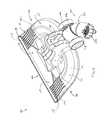
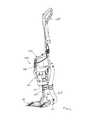
- FIG. 6is a front perspective view of a surface cleaning apparatus comprising the surface cleaning head of FIG. 1 ;
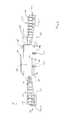
- FIG. 7is a cross-section taken along line 7 - 7 in FIG. 3 ;
- FIG. 8is a cross-section taken along line 8 - 8 in FIG. 3 ;
- FIG. 9is a cross-section taken along line 9 - 9 in FIG. 3 .
- the surface cleaning head 100is connectable in air flow communication to a surface cleaning apparatus 600 , such as a vacuum cleaner (e.g., a canister or an upright vacuum cleaner), and preferably, an upright vacuum cleaner.
- a vacuum cleanere.g., a canister or an upright vacuum cleaner
- an upright vacuum cleanere.g., an upright vacuum cleaner
- the surface cleaning head 100comprises a front end 102 , and a rear end 104 .
- the surface cleaning headfurther comprises first 106 and second 108 opposed lateral sides.
- a top outer surface 110 and a bottom outer surface 112each extend between the front end 102 and the rear end 104 , and the opposed lateral sides 106 , 108 .
- the top 110 and bottom 112 outer surfacesform essentially all of the outer surface 101 of the surface cleaning head.
- the surface cleaning head 100may be of any shape and preferably has a front 102 that is straight.
- the top 110 and bottom 112 outer surfacesform essentially all of the outer surface 101 of the surface cleaning head.
- the surface cleaning head 100may be constructed from any number of parts.
- a simplified construction that may be usedis exemplified.
- a clam shell constructionis utilized whereby a lower open sided air chamber is formed by having a portion of the top member of the clam shell extend forward of the lower clam shell portion.
- This constructionmay be used by itself or with other features of a surface cleaning head set out herein.
- the surface cleaning head 100comprises a upper section 114 , and a lower section 116 .
- the upper section 114has an outer surface 115
- the lower section 116has an outer surface 117 .
- the outer surfaces 115 , 117are defined as surfaces that are visible when the surface cleaning head 100 is assembled.
- upper section 114is an integrally formed plate
- lower section 116is an integrally formed plate.
- the front portion 118 of the upper section 114extends forwardly of the lower section 116 and has a length “L” as exemplified in FIGS. 2 and 3 .
- front portiondefines a lower open sided air flow chamber.
- the outer surface 115has an upward facing portion 159 , and a downward facing portion 161 and has a thickness “T” that is less than length “L”.
- the downward facing portion 161forms a front portion 120 of bottom surface 112 .
- the outer surface 117 of the lower section 116forms a rear portion 121 of the bottom surface 112 .
- the front portion 118 of the upper section 114comprises a single layer of material.
- the front portion 118 of the upper section 114may comprise a single layer of plastic.
- the plasticmay have a thickness less than 0.1 inches.
- reinforcing ribs 179are provided on the upward facing portion 159 of the outer surface 115 of upper section 114 .
- the reinforcing ribs 179may prevent front portion 118 from breaking or deflecting when surface cleaning head 100 is in use, for example if front portion 118 hits a wall.
- a first set of reinforcing ribs 177is provided adjacent the first lateral side 106
- a second set 175 of reinforcing ribsis provided adjacent the second lateral side 108 .
- the reinforcing ribsare integrally molded with upper section 114
- the reinforcing ribs 179extend upwardly and rearwardly from the front end 102 , and increase in height going rearwardly.
- the ribs 179merge with a rear portion 147 of the upper section 114 , which is at a higher height than the front portion. Accordingly, in the exemplified embodiment, the ribs are at a transition portion 151 of the upper section 114 .
- the outer surface 115 of the upper section 114 , and the outer surface 117 of the lower section 116comprise essentially all of the outer surface of the surface cleaning head. That is, the outer surface 115 of the upper section 114 , and the outer surface 117 of the lower section 116 comprise all of the outer surface of the surface cleaning head, excluding an optional pivot mount cover 193 , as will be described hereinbelow.
- other sectionse.g. other plates
- the transparent sectionmay be fabricated from a transparent plastic, such as polycarbonate. More preferably, all of the front portion 118 is transparent. For example, in the exemplified embodiment, all of upper section 114 is transparent, including all of front portion 118 . Preferably, the lower section 116 is opaque. It will be appreciated that upper section 114 may be tinted.
- the surface cleaning apparatuscomprises an airflow passage extending from a dirty air inlet 130 to an air outlet 134 .
- the airflow passageextends under the section of the front portion 118 that is transparent. More preferably, the airflow passage comprises at least a section that has an open lower side.
- the dirty air inlet 130is provided at front end 102 .
- a first airflow chamber 128extends rearwardly from dirty air inlet 130 .
- the airflow chamber 128is integrally formed in front portion 118 of upper section 114 . More particularly, the outer surface 115 of the upper section is contoured to form a top wall 190 , and opposed side walls 192 , 194 , of the airflow chamber 128 . Accordingly, the airflow chamber 128 extends under front portion 118 , and as all of front portion 118 is transparent, the airflow chamber 128 provides the portion of the airflow passage that extends under the transparent section of front portion 118 .
- all of the lower side 188 of the airflow chamberwhich extends between the air inlet 130 , the rear 132 , and the sides 192 , 194 , is open. In alternate embodiments, only a portion may be open. Any lower open sided construction may be used.
- front portion 118may be transparent and may have sufficient strength to permit the front of the cleaning head to comprise a single layer of plastic. If an open sided air flow chamber is provided below front portion 118 , which is preferred, then a user may view the air channel and determine if a blockage occurs.
- An advantage of the transition regionis that reinforcing ribs may be provided to provide rigidity to front portion 118 .
- front portion 118may vibrate or flex, particularly at high suction. The may affect the efficiency of the vacuum cleaner due to variations in air flow rate in the lower open sided air flow chamber.
- Rear end 132 of airflow chamber 128may be in communication with a manifold 198 , which is in communication with an enclosed passage 140 via an enclosed passage inlet 136 .
- the enclosed passage 140extends rearwardly from the enclosed passage inlet 136 .
- a swivel joint 137is mounted to a rear end of the enclosed passage 140 , and is in airflow communication with the enclosed passage 140 .
- the swivel jointis mountable in airflow communication with the surface cleaning apparatus 600 , and comprises the air outlet 134 of the surface cleaning head 100 . Any other connection known in the vacuum cleaner arts may be used.
- the surface cleaning apparatusfurther comprises a second airflow chamber 122 , and a third airflow chamber 123 , which form a portion of the airflow passage.
- the second airflow chamberhas an inlet 124 at first lateral side 106 , and an outlet 126 in communication with manifold 198 .
- the third airflow chamber 123has an inlet 125 at second lateral side 108 , and an outlet 127 in communication with manifold 198 .
- Inlets 124 and 125form auxiliary dirty air inlets to surface cleaning head 100 .
- Both the second 122 and third 123 airflow chambersare preferably integrally formed in front portion 118 of upper section 114 .
- the outer surface 115 of the upper section 114may be contoured to form a top wall 133 , and opposed side walls 135 , 139 of the second airflow chamber 122 , and to form a top wall 141 and opposed side walls 143 , 145 of the third airflow chamber 123 .
- the second airflow chamber 122has an open lower side 129
- the third airflow chamber 123has an open lower side 131 .
- inlets 124 , 125may not be provided.
- the surface cleaning head 100is preferably configured to transition from a low pile carpet to a high pile carpet.
- This designmay be used by itself or with any other feature disclosed herein.
- the front portion 118 of top section 114comprises an upwardly curved lip 199 .
- Lip 199is provided at the front 102 of the surface cleaning head 100 , above dirty air inlet 130 . Accordingly, if surface cleaning head 100 is pushed from a low pile carpet to a high pile carpet, lip 199 will serve as a ramp, and aid in lifting the surface cleaning head 100 from the low pile carpet onto the high pile carpet.
- the sidewalls 192 , 194 of the first airflow passageare formed from triangular members 167 and 169 .
- the triangular members 167 , 169may curve upwardly together with lip 199 at front end 102 . This is shown in FIG. 7 .
- the front or leading edge of any side wall for the open lower sided air flow channelmay be chamfered, curved or radiused.
- ribs that act as carpet holdersmay be provided, which, in use, hold down a carpet, and prevent the carpet from being lifted upward off of a surface by the flow of air through the open sided airflow passages 128 , 122 , 123 .
- This designmay be used by itself with an lower open sided air flow chamber or with any other feature disclosed herein.
- two carpet holders 195are provided, which extend downwardly from top wall 190 of first passage 128 and preferably extend in a direction of flow.
- the surface cleaning head 100preferably comprises at least front wheels.
- the surface cleaning head 100comprises first 142 and second 144 front wheel assemblies, and first 146 and second 148 rear wheels.
- the front wheel assemblies 142 , 144are rotatable about vertical axes. More preferably, the front wheel assemblies 142 , 144 are rotatable about vertical axes, and comprise wheels that are rotatable about horizontal axes.
- the front wheelsmay be swivel, caster or ball wheels. This configuration of wheels may be used by itself or with any other feature disclosed herein.
- the first front wheel assembly 142comprises a first front wheel 150
- second front wheel 144 assemblycomprises a second wheel front 152
- the first front wheel assembly 142further comprises a first bracket 154 , having outwardly extending arms 156 a , 156 b .
- the first front wheel 150is mounted on a first axle 158 , which extends horizontally between the arms 156 a , 156 b . Accordingly, the first front wheel 150 is rotatable about a horizontal axis H 1 defined by first axle 158 .
- the second front wheel assembly 144further comprises a second bracket 160 , having outwardly extending arms 162 a , 162 b .
- the second front wheel 152is mounted on a second axle 164 which extends horizontally between the arms 162 a , 162 b . Accordingly, the second front wheel 152 is rotatable about a horizontal axis H 2 defined by axle 164 .
- the first bracket 154comprises a first vertically extending portion 166 provided above the outwardly extending arms 156
- the second bracket 160comprises a second vertically extending portion 168 provided above the outwardly extending arms 162 .
- First 170 and second 172 vertical pinsare mounted to the lower section 116 , and extend downwardly therefrom.
- the first vertically extending portion 166is rotatably received on the first pin 170
- the second vertically extending portion 168is rotatably received on the second pin 172 .
- the first 154 and second 160 bracketsare rotatable about first and second vertical pins 170 and 172 , respectively, to rotate first 142 and second 144 front wheel assemblies about vertical axes V 1 and V 2 , respectively.
- the horizontal axis of rotation H 1 of the first front wheel 150is spaced from the vertical axis of rotation V 1 of the first front wheel assembly 142
- the horizontal axis of rotation H 2 of the second front wheel 152is spaced from the vertical axis of rotation V 1 of the first front wheel assembly 144 .
- outwardly extending arms 156 a , 156 bextend laterally away from vertically extending portion 166 , such that axle 158 , which defines axis H 1 , is spaced from vertically extending portion 166 , which defines axis V 1 .
- outwardly extending arms 162 a , 162 bextend laterally away from vertically extending portion 168 , such that axle 164 , which defines axis H 2 , is spaced from vertically extending portion 168 , which defines axis V 2 .
- the rear wheels 146 , 148are rotatable about horizontal axes H 3 .
- the rear wheels 146 , 148are mounted on axles 174 and 176 , respectively, which are fixedly mounted on opposed sides of enclosed passage 140 , adjacent rear end 104 .
- the front wheelsare positioned rearwardly of the enclosed passage inlet 136 .
- the rear wheels 146 , 148are positioned closer together than the front wheel assemblies 142 , 144 .
- the front wheel assemblies 142 , 144are positioned adjacent lateral sides 106 , 108 , respectively of the surface cleaning head 100 .
- the rear wheels 146 , 148are positioned on opposed sides of enclosed passage 140 .
- the front wheelsare positioned under the lower section 116 .
- the front wheelsare mounted to the outer surface 117 of the lower section 116 .
- a portion of each front wheel assembly 142 , 144is recessed upwards from the bottom surface 112 of the surface cleaning head 100 .
- a first recess 178 and a second recess 180are provided in lower section 116 , and extend upwardly.
- the first front wheel assembly 142is mounted in the first recess 178 , such that bracket 154 is completely received within the first recess 178 , and a portion of wheel 150 extends from the first recess 178 .
- the second front wheel assembly 144is mounted in the second recess 180 , such that bracket 160 is completely received within the first recess 180 , and a portion of wheel 152 extends from the second recess 180 . As shown in FIG. 3 , this allows bottom surface 112 to sit in close proximity to a floor F.
- the front wheels 150 , 152have a smaller diameter than the rear wheels 146 , 148 .
- surface cleaning head 100may further comprise a pivot joint 182 , which is mounted to upper section 114 , and is covered by a cover 193 .
- the pivot joint 182comprises laterally opposed apertures 184 (only one aperture shown).
- the pivot joint 182is positioned between the front wheel assemblies 142 , 144 and the rear wheels 146 , 148 .
- a support 606 of the surface cleaning apparatus 600is pivotally mounted to the pivot joint 182 by a pivot pins 605 a , 605 b.
- a surface cleaning apparatus 600comprising surface cleaning head 100 is shown. It will be appreciated that surface cleaning head 100 may be mounted to any suitable surface cleaning apparatus, and surface cleaning apparatus 600 is exemplary only.
- surface cleaning apparatus 600comprises a flexible hose 602 , which is mounted to swivel joint 137 and is in fluid communication with air outlet 134 .
- a rigid conduitmay also be used.
- Hose 602extends upwardly to a cleaning unit 604 .
- the cleaning unit 604is mounted to support 606 , which is pivotally mounted to pivot joint 182 of surface cleaning head 100 .
- the cleaning unit 604includes a cleaning apparatus 608 .
- the cleaning apparatus 608is in fluid communication with hose 602 , and serves to separate dirt from air.
- the cleaning apparatus 608may be any type of cleaning apparatus, such as one or more cyclonic cleaning units, and/or one or more filters.
- the cleaning unitfurther comprises a suction motor 610 , which draws air into the dirty air inlets of surface cleaning head, through surface cleaning head 100 to outlet 134 , through house 602 , through cleaning apparatus 608 , and out of a clean air outlet 612 of the surface cleaning apparatus 600 .
- a handle 614is mounted to cleaning unit 604 , and may be gripped by a user to move surface cleaning head 100 along a surface.
Landscapes
- Engineering & Computer Science (AREA)
- Mechanical Engineering (AREA)
- Nozzles For Electric Vacuum Cleaners (AREA)
Abstract
Description
Claims (22)
Applications Claiming Priority (2)
| Application Number | Priority Date | Filing Date | Title |
|---|---|---|---|
| CA2658369 | 2009-03-13 | ||
| CA2658369ACA2658369A1 (en) | 2009-03-13 | 2009-03-13 | Surface cleaning head |
Publications (2)
| Publication Number | Publication Date |
|---|---|
| US20100229337A1 US20100229337A1 (en) | 2010-09-16 |
| US9161666B2true US9161666B2 (en) | 2015-10-20 |
Family
ID=42729478
Family Applications (1)
| Application Number | Title | Priority Date | Filing Date |
|---|---|---|---|
| US12/721,286Active2031-04-17US9161666B2 (en) | 2009-03-13 | 2010-03-10 | Surface cleaning head |
Country Status (2)
| Country | Link |
|---|---|
| US (1) | US9161666B2 (en) |
| CA (1) | CA2658369A1 (en) |
Cited By (17)
| Publication number | Priority date | Publication date | Assignee | Title |
|---|---|---|---|---|
| FR3149181A1 (en) | 2023-06-05 | 2024-12-06 | Seb S.A. | Cleaning device equipped with a waste guide channel |
| FR3149182A1 (en) | 2023-06-05 | 2024-12-06 | Seb S.A. | Cleaning device equipped with a waste guide channel |
| FR3149180A1 (en) | 2023-06-05 | 2024-12-06 | Seb S.A. | Cleaning device equipped with a waste guide channel |
| US12234087B2 (en) | 2016-12-28 | 2025-02-25 | Omachron Intellectual Property Inc. | Dust and allergen control for surface cleaning apparatus |
| US12251716B2 (en) | 2016-12-27 | 2025-03-18 | Omachron Intellectual Property Inc. | Surface cleaning apparatus |
| US12256877B2 (en) | 2017-09-15 | 2025-03-25 | Omachron Intellectual Property Inc. | Surface cleaning apparatus |
| US12295538B2 (en) | 2018-08-13 | 2025-05-13 | Omachron Intellectual Property Inc. | Cyclonic air treatment member and surface cleaning apparatus including the same |
| US12303096B2 (en) | 2020-04-22 | 2025-05-20 | Omachron Intellectual Property Inc. | Robotic vacuum cleaner with dirt enclosing member and method of using the same |
| US12326151B2 (en) | 2021-02-17 | 2025-06-10 | Omachron Intellectual Property Inc. | Fan and motor assembly for an appliance such as a vacuum cleaner and a vacuum cleaner having same |
| US12342978B2 (en) | 2017-09-15 | 2025-07-01 | Omachron Intellectual Property Inc. | Surface cleaning apparatus |
| US12350689B2 (en) | 2019-01-23 | 2025-07-08 | Omachron Intellectual Property Inc. | Surface cleaning apparatus |
| US12349853B2 (en) | 2018-03-29 | 2025-07-08 | Omachron Intellectual Property Inc. | Rotatable brush for surface cleaning apparatus |
| US12357140B2 (en) | 2013-02-28 | 2025-07-15 | Omachron Intellectual Property Inc. | Cyclone such as for use in a surface cleaning apparatus |
| US12390062B2 (en) | 2016-01-08 | 2025-08-19 | Omachron Intellectual Property Inc. | Hand carryable surface cleaning apparatus |
| US12410813B2 (en) | 2020-04-01 | 2025-09-09 | Omachron Intellectual Property Inc. | Household appliance having an improved fan and motor assembly and fan and motor assembly for same |
| US12426752B2 (en) | 2009-03-13 | 2025-09-30 | Omachron Intellectual Property Inc. | Surface cleaning apparatus |
| US12441537B2 (en) | 2019-09-26 | 2025-10-14 | Omachron Intellectual Property Inc. | Dust and allergen control for surface cleaning apparatus |
Families Citing this family (17)
| Publication number | Priority date | Publication date | Assignee | Title |
|---|---|---|---|---|
| US8938851B2 (en) | 2011-06-22 | 2015-01-27 | Panasonic Corporation Of North America | Nozzle assembly with one piece body |
| US20160157690A1 (en)* | 2014-12-05 | 2016-06-09 | Panasonic Corporation Of North America | Upright vacuum cleaner with swivel connection between nozzle and handle assemblies |
| US10022027B2 (en) | 2014-12-17 | 2018-07-17 | Omachron Intellectual Property Inc. | All in the head surface cleaning apparatus |
| US9883781B2 (en) | 2014-12-17 | 2018-02-06 | Omachron Intellectual Property Inc. | All in the head surface cleaning apparatus |
| US9775479B2 (en) | 2014-12-17 | 2017-10-03 | Omachron Intellectual Property Inc. | All in the head surface cleaning apparatus |
| US9717383B2 (en) | 2014-12-17 | 2017-08-01 | Omachron Intellectual Property Inc. | All in the head surface cleaning apparatus |
| US9901229B2 (en) | 2014-12-17 | 2018-02-27 | Omachron Intellectual Property Inc. | All in the head surface cleaning apparatus |
| US10357136B2 (en) | 2014-12-17 | 2019-07-23 | Omachron Intellectual Property Inc. | All in the head surface cleaning apparatus |
| US11202544B2 (en) | 2014-12-17 | 2021-12-21 | Omachron Intellectual Property Inc. | All in the head surface cleaning apparatus |
| US9775480B2 (en) | 2014-12-17 | 2017-10-03 | Omachron Intellectual Property Inc. | All in the head surface cleaning apparatus |
| US9545180B2 (en)* | 2014-12-17 | 2017-01-17 | Omachron Intellectual Property Inc. | All in the head surface cleaning apparatus |
| US9668630B2 (en) | 2014-12-17 | 2017-06-06 | Omachron Intellectual Property Inc. | All in the head surface cleaning apparatus |
| US9795264B2 (en) | 2014-12-17 | 2017-10-24 | Omachron Intellectual Property Inc. | All in the head surface cleaning apparatus |
| US9668624B2 (en) | 2014-12-17 | 2017-06-06 | Omachron Intellectual Property Inc. | All in the head surface cleaning apparatus |
| US9775481B2 (en) | 2014-12-17 | 2017-10-03 | Omachron Intellectual Property Inc. | All in the head surface cleaning apparatus |
| GB201616598D0 (en)* | 2016-09-30 | 2016-11-16 | Grey Technology Limited | Cleaning head for a vacuum cleaner |
| GB201907851D0 (en)* | 2019-06-03 | 2019-07-17 | Dyson Technology Ltd | A cleaner head for a vacuum cleaner |
Citations (12)
| Publication number | Priority date | Publication date | Assignee | Title |
|---|---|---|---|---|
| US1782882A (en)* | 1927-12-13 | 1930-11-25 | Rippey Samuel Howard | Vacuum-cleaner nozzle |
| US2205877A (en)* | 1937-09-17 | 1940-06-25 | Electric Vacuum Cleaner Co | Surface cleaning tool |
| US3036325A (en)* | 1961-02-15 | 1962-05-29 | Parks Cramer Co | Collapsible nozzle for textile suction cleaner |
| US4395794A (en)* | 1979-05-09 | 1983-08-02 | Ing. Alfred Schmidt Gmbh | Device to take up refuse by vacuum intake air |
| US4665582A (en)* | 1985-02-22 | 1987-05-19 | National Union Electric Corp. | Lightweight battery powered suction broom |
| US5101534A (en)* | 1989-04-17 | 1992-04-07 | Hitachi, Ltd. | Suction nozzle with rotary brush for vacuum cleaner |
| US5557822A (en)* | 1993-10-22 | 1996-09-24 | Sharp Kabushiki Kaisha | Electric vacuum cleaner |
| US20060101604A1 (en)* | 2004-11-17 | 2006-05-18 | Frederick Lynn A | Mode control arrangement for a floor |
| US20060179604A1 (en)* | 2002-12-06 | 2006-08-17 | Boddy Andrew D | Head for a suction cleaner |
| US20080047093A1 (en)* | 2006-08-28 | 2008-02-28 | Gordon Evan A | Battery powered extractor |
| US20090094788A1 (en)* | 2007-03-05 | 2009-04-16 | Bissell Homecare, Inc. | Surface cleaning implemenent with magnetic coupled fan |
| US8151408B2 (en)* | 2007-08-30 | 2012-04-10 | Miele & Cie. Kg | Upright vacuum cleaner |
- 2009
- 2009-03-13CACA2658369Apatent/CA2658369A1/ennot_activeAbandoned
- 2010
- 2010-03-10USUS12/721,286patent/US9161666B2/enactiveActive
Patent Citations (13)
| Publication number | Priority date | Publication date | Assignee | Title |
|---|---|---|---|---|
| US1782882A (en)* | 1927-12-13 | 1930-11-25 | Rippey Samuel Howard | Vacuum-cleaner nozzle |
| US2205877A (en)* | 1937-09-17 | 1940-06-25 | Electric Vacuum Cleaner Co | Surface cleaning tool |
| US3036325A (en)* | 1961-02-15 | 1962-05-29 | Parks Cramer Co | Collapsible nozzle for textile suction cleaner |
| US4395794A (en)* | 1979-05-09 | 1983-08-02 | Ing. Alfred Schmidt Gmbh | Device to take up refuse by vacuum intake air |
| US4665582A (en)* | 1985-02-22 | 1987-05-19 | National Union Electric Corp. | Lightweight battery powered suction broom |
| US5101534A (en)* | 1989-04-17 | 1992-04-07 | Hitachi, Ltd. | Suction nozzle with rotary brush for vacuum cleaner |
| US5557822A (en)* | 1993-10-22 | 1996-09-24 | Sharp Kabushiki Kaisha | Electric vacuum cleaner |
| US20060179604A1 (en)* | 2002-12-06 | 2006-08-17 | Boddy Andrew D | Head for a suction cleaner |
| US20060101604A1 (en)* | 2004-11-17 | 2006-05-18 | Frederick Lynn A | Mode control arrangement for a floor |
| US7673370B2 (en)* | 2004-11-17 | 2010-03-09 | Techtronic Floor Care Technology Limited | Mode control arrangement for a floor |
| US20080047093A1 (en)* | 2006-08-28 | 2008-02-28 | Gordon Evan A | Battery powered extractor |
| US20090094788A1 (en)* | 2007-03-05 | 2009-04-16 | Bissell Homecare, Inc. | Surface cleaning implemenent with magnetic coupled fan |
| US8151408B2 (en)* | 2007-08-30 | 2012-04-10 | Miele & Cie. Kg | Upright vacuum cleaner |
Cited By (26)
| Publication number | Priority date | Publication date | Assignee | Title |
|---|---|---|---|---|
| US12426752B2 (en) | 2009-03-13 | 2025-09-30 | Omachron Intellectual Property Inc. | Surface cleaning apparatus |
| US12357140B2 (en) | 2013-02-28 | 2025-07-15 | Omachron Intellectual Property Inc. | Cyclone such as for use in a surface cleaning apparatus |
| US12390062B2 (en) | 2016-01-08 | 2025-08-19 | Omachron Intellectual Property Inc. | Hand carryable surface cleaning apparatus |
| US12251716B2 (en) | 2016-12-27 | 2025-03-18 | Omachron Intellectual Property Inc. | Surface cleaning apparatus |
| US12397987B2 (en) | 2016-12-28 | 2025-08-26 | Omachron Intellectual Property Inc. | Dust and allergen control for surface cleaning apparatus |
| US12297039B2 (en) | 2016-12-28 | 2025-05-13 | Omachron Intellectual Property Inc. | Dust and allergen control for surface cleaning apparatus |
| US12234087B2 (en) | 2016-12-28 | 2025-02-25 | Omachron Intellectual Property Inc. | Dust and allergen control for surface cleaning apparatus |
| US12234088B2 (en) | 2016-12-28 | 2025-02-25 | Omachron Intellectual Property Inc. | Dust and allergen control for surface cleaning apparatus |
| US12256877B2 (en) | 2017-09-15 | 2025-03-25 | Omachron Intellectual Property Inc. | Surface cleaning apparatus |
| US12342978B2 (en) | 2017-09-15 | 2025-07-01 | Omachron Intellectual Property Inc. | Surface cleaning apparatus |
| US12349853B2 (en) | 2018-03-29 | 2025-07-08 | Omachron Intellectual Property Inc. | Rotatable brush for surface cleaning apparatus |
| US12295538B2 (en) | 2018-08-13 | 2025-05-13 | Omachron Intellectual Property Inc. | Cyclonic air treatment member and surface cleaning apparatus including the same |
| US12350689B2 (en) | 2019-01-23 | 2025-07-08 | Omachron Intellectual Property Inc. | Surface cleaning apparatus |
| US12441537B2 (en) | 2019-09-26 | 2025-10-14 | Omachron Intellectual Property Inc. | Dust and allergen control for surface cleaning apparatus |
| US12410813B2 (en) | 2020-04-01 | 2025-09-09 | Omachron Intellectual Property Inc. | Household appliance having an improved fan and motor assembly and fan and motor assembly for same |
| US12303096B2 (en) | 2020-04-22 | 2025-05-20 | Omachron Intellectual Property Inc. | Robotic vacuum cleaner with dirt enclosing member and method of using the same |
| US12326151B2 (en) | 2021-02-17 | 2025-06-10 | Omachron Intellectual Property Inc. | Fan and motor assembly for an appliance such as a vacuum cleaner and a vacuum cleaner having same |
| EP4473888A1 (en) | 2023-06-05 | 2024-12-11 | Seb S.A. | Cleaning device with a waste guiding channel |
| FR3149181A1 (en) | 2023-06-05 | 2024-12-06 | Seb S.A. | Cleaning device equipped with a waste guide channel |
| WO2024252090A1 (en) | 2023-06-05 | 2024-12-12 | Seb S.A. | Cleaning device equipped with a waste guide channel |
| EP4473889A1 (en) | 2023-06-05 | 2024-12-11 | Seb S.A. | Cleaning device with a waste guiding channel |
| EP4473890A1 (en) | 2023-06-05 | 2024-12-11 | Seb S.A. | Cleaning device with a waste guiding channel |
| FR3149180A1 (en) | 2023-06-05 | 2024-12-06 | Seb S.A. | Cleaning device equipped with a waste guide channel |
| WO2024252089A1 (en) | 2023-06-05 | 2024-12-12 | Seb S.A. | Cleaning device equipped with a waste guide channel |
| FR3149182A1 (en) | 2023-06-05 | 2024-12-06 | Seb S.A. | Cleaning device equipped with a waste guide channel |
| WO2024252091A1 (en) | 2023-06-05 | 2024-12-12 | Seb S.A. | Cleaning device equipped with a waste guide channel |
Also Published As
| Publication number | Publication date |
|---|---|
| US20100229337A1 (en) | 2010-09-16 |
| CA2658369A1 (en) | 2010-09-13 |
Similar Documents
| Publication | Publication Date | Title |
|---|---|---|
| US9161666B2 (en) | Surface cleaning head | |
| US9027203B2 (en) | Surface cleaning apparatus | |
| CA2658160A1 (en) | Surface cleaning head | |
| US11622659B2 (en) | Portable surface cleaning apparatus | |
| US11571095B2 (en) | Cyclonic air treatment apparatus | |
| CA2658366A1 (en) | Surface cleaning head | |
| US8510907B2 (en) | Cyclonic surface cleaning apparatus | |
| CA2658644A1 (en) | Surface cleaning head | |
| AU2005319023B2 (en) | Steerable upright vacuum cleaner | |
| KR101153256B1 (en) | An accessory for a cleaning appliance | |
| US20030140449A1 (en) | Vacuum cleaner nozzle assembly having edge-cleaning ducts | |
| JP2010512196A (en) | Cleaning head with multiple struts | |
| US20100229326A1 (en) | Hand vacuum cleaner | |
| CA2883018A1 (en) | Hand vacuum cleaner | |
| US10799080B2 (en) | Cleaner | |
| CA2658005A1 (en) | Configuration of a surface cleaning apparatus | |
| US12324557B2 (en) | Portable surface cleaning apparatus | |
| US12048409B2 (en) | Portable surface cleaning apparatus | |
| CA2658033A1 (en) | Nozzle for a hand vacuum cleaner | |
| CA2658017A1 (en) | Nozzle for a cyclonic hand vacuum cleaner |
Legal Events
| Date | Code | Title | Description |
|---|---|---|---|
| AS | Assignment | Owner name:G.B.D. CORP., BAHAMAS Free format text:ASSIGNMENT OF ASSIGNORS INTEREST;ASSIGNOR:CONRAD, WAYNE ERNEST;REEL/FRAME:024060/0569 Effective date:20090309 | |
| AS | Assignment | Owner name:OMACHRON INTELLECTUAL PROPERTY INC., CANADA Free format text:ASSIGNMENT OF ASSIGNORS INTEREST;ASSIGNOR:CONRAD IN TRUST, WAYNE;REEL/FRAME:036175/0600 Effective date:20150622 Owner name:CONRAD IN TRUST, WAYNE, CANADA Free format text:ASSIGNMENT OF ASSIGNORS INTEREST;ASSIGNOR:G.B.D. CORP.;REEL/FRAME:036175/0514 Effective date:20150622 | |
| STCF | Information on status: patent grant | Free format text:PATENTED CASE | |
| MAFP | Maintenance fee payment | Free format text:PAYMENT OF MAINTENANCE FEE, 4TH YEAR, LARGE ENTITY (ORIGINAL EVENT CODE: M1551); ENTITY STATUS OF PATENT OWNER: LARGE ENTITY Year of fee payment:4 | |
| MAFP | Maintenance fee payment | Free format text:PAYMENT OF MAINTENANCE FEE, 8TH YEAR, LARGE ENTITY (ORIGINAL EVENT CODE: M1552); ENTITY STATUS OF PATENT OWNER: LARGE ENTITY Year of fee payment:8 |