US9161658B2 - Single cup brewer - Google Patents
Single cup brewerDownload PDFInfo
- Publication number
- US9161658B2 US9161658B2US13/634,792US201113634792AUS9161658B2US 9161658 B2US9161658 B2US 9161658B2US 201113634792 AUS201113634792 AUS 201113634792AUS 9161658 B2US9161658 B2US 9161658B2
- Authority
- US
- United States
- Prior art keywords
- beverage
- water
- substance
- holder
- receiving
- Prior art date
- Legal status (The legal status is an assumption and is not a legal conclusion. Google has not performed a legal analysis and makes no representation as to the accuracy of the status listed.)
- Active, expires
Links
Images


Classifications
- A—HUMAN NECESSITIES
- A47—FURNITURE; DOMESTIC ARTICLES OR APPLIANCES; COFFEE MILLS; SPICE MILLS; SUCTION CLEANERS IN GENERAL
- A47J—KITCHEN EQUIPMENT; COFFEE MILLS; SPICE MILLS; APPARATUS FOR MAKING BEVERAGES
- A47J31/00—Apparatus for making beverages
- A47J31/44—Parts or details or accessories of beverage-making apparatus
- A47J31/54—Water boiling vessels in beverage making machines
- A—HUMAN NECESSITIES
- A47—FURNITURE; DOMESTIC ARTICLES OR APPLIANCES; COFFEE MILLS; SPICE MILLS; SUCTION CLEANERS IN GENERAL
- A47J—KITCHEN EQUIPMENT; COFFEE MILLS; SPICE MILLS; APPARATUS FOR MAKING BEVERAGES
- A47J31/00—Apparatus for making beverages
- A47J31/06—Filters or strainers for coffee or tea makers ; Holders therefor
- A47J31/0657—Filters or strainers for coffee or tea makers ; Holders therefor for brewing coffee under pressure, e.g. for espresso machines
- A47J31/0663—Filters or strainers for coffee or tea makers ; Holders therefor for brewing coffee under pressure, e.g. for espresso machines to be used with loose coffee
- A—HUMAN NECESSITIES
- A47—FURNITURE; DOMESTIC ARTICLES OR APPLIANCES; COFFEE MILLS; SPICE MILLS; SUCTION CLEANERS IN GENERAL
- A47J—KITCHEN EQUIPMENT; COFFEE MILLS; SPICE MILLS; APPARATUS FOR MAKING BEVERAGES
- A47J31/00—Apparatus for making beverages
- A47J31/06—Filters or strainers for coffee or tea makers ; Holders therefor
- A47J31/0657—Filters or strainers for coffee or tea makers ; Holders therefor for brewing coffee under pressure, e.g. for espresso machines
- A47J31/0668—Filters or strainers for coffee or tea makers ; Holders therefor for brewing coffee under pressure, e.g. for espresso machines specially adapted for cartridges
- A47J31/0673—Means to perforate the cartridge for creating the beverage outlet
- A—HUMAN NECESSITIES
- A47—FURNITURE; DOMESTIC ARTICLES OR APPLIANCES; COFFEE MILLS; SPICE MILLS; SUCTION CLEANERS IN GENERAL
- A47J—KITCHEN EQUIPMENT; COFFEE MILLS; SPICE MILLS; APPARATUS FOR MAKING BEVERAGES
- A47J31/00—Apparatus for making beverages
- A47J31/44—Parts or details or accessories of beverage-making apparatus
- A47J31/4403—Constructional details
- A47J31/446—Filter holding means; Attachment of filters to beverage-making apparatus
- A47J31/4467—Filter holding means; Attachment of filters to beverage-making apparatus by means of linear guides, e.g. drawer-type engagement
- A—HUMAN NECESSITIES
- A47—FURNITURE; DOMESTIC ARTICLES OR APPLIANCES; COFFEE MILLS; SPICE MILLS; SUCTION CLEANERS IN GENERAL
- A47J—KITCHEN EQUIPMENT; COFFEE MILLS; SPICE MILLS; APPARATUS FOR MAKING BEVERAGES
- A47J31/00—Apparatus for making beverages
- A47J31/44—Parts or details or accessories of beverage-making apparatus
- A47J31/46—Dispensing spouts, pumps, drain valves or like liquid transporting devices
Definitions
- Beverage making apparatuswhich include a reservoir for holding a portion of heated water.
- the reservoirincludes an inlet into the reservoir and an outlet from the reservoir and a heating element in association with the reservoir.
- Wateris supplied to the reservoir, heated, and then moved to a spray head for dispensing over a beverage making substance. Heated water dispensed over the beverage making substance infuses the substance and produces a beverage.
- FIG. 1is a perspective view of a single cup brewer which includes a housing have a body extending from a base and a hood extending from the body, a brewing substance holder is provided and removably attachable to an engagement area of the hood, a cover is provided over a portion of the hood which receives water therein for use in the beverage making process;
- FIG. 2is a perspective view of the brewer in which the holder has been removed from the engagement area to reveal a cavity for receipt of a brewing substance, the cover has been displaced from the holder to reveal a filling area, a drip tray area has been removed to reveal a collection area;
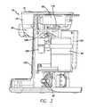
- FIG. 3is a rear perspective view which has been partially fragmented to reveal various components within the body of the housing including the heated water reservoir, fill basin, controller, air pump, water pump, and related structures;
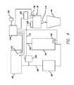
- FIG. 4is an illustrative general schematic diagram showing the overall brewing system of the brewer
- FIG. 5is a drawing showing the relationship of the exploded illustrations of FIGS. 5A , 5 B, and 5 C;
- FIG. 5Ais an enlarged exploded view of a portion of the brewer including the pour-in basin, spray head, control switch assembly and holder assembly shown in an exploded view relative to other views as shown in FIG. 5 b and FIG. 5 c;
- FIG. 5Bshows an exploded view of a water moving assembly including a water pump, heated water reservoir, air pump and vent valve which operate to move water and air through the brewer during operation;
- FIG. 5Cis an exploded view of the brewer housing which has been exploded to reveal other components contained therein, FIGS. 5A , 5 B and 5 C providing a combined exploded view of the entire brewer assembly;
- FIG. 6is a perspective view of a holder which is used for holding a pre-packaged filter cartridge cup containing brewing substance with a cover displaceably attached to a corresponding holder defining a cavity for receiving the cartridge;
- FIG. 7shows a partial fragmentary side elevational view of a holder with a cartridge (not in cross section) placed therein and shows the first of a series of progressions in which the cartridge is engaged in the holder for use during a brewing process;
- FIG. 8shows the view of FIG. 7 in which a cover has been advanced to a position over the top surface of the cartridge (not in cross section) and in which the surfaces of the cartridge have not been pierced by multiple cannulae retained on the cover and in the cavity of the holder;
- FIG. 9is a view of the illustrations of FIGS. 7 and 8 in which the cover has been positioned over the cartridge with the multiple cannulae piercing corresponding surfaces of the cartridge for delivering water to a brewing substance retained in the filter portion of the cartridge, and the holder having a compatible engagement structure for retention on the engagement area of the hood;
- FIG. 10is a side elevational cross-sectional view of the brewer with the pre-packaged beverage brewing cartridge retained in the holder for use in the brewing process;
- FIG. 11is an enlarged cross-sectional view as shown in FIG. 10 showing the holder position below and mating with a spray head for delivering water to the holder system, the spray head is the same spray head that us used for distributing water over a pod retained in a pod holed configured for attachment to the same brewer; and
- FIG. 12is an enlarged cross-sectional view of the holder.
- a brewer 20includes a housing 24 having a body 28 extending above a base 30 .
- a hood 34extends from the body 28 over a portion of the base 30 .
- a beverage substance holder or holder 36is retained underneath a portion of the hood 34 .
- the base 30includes a drip tray 40 on top of which a cup or container 44 may be placed. The container 44 is position underneath the beverage substance holder 36 so that when the brewer 20 operates a brewing cycle a volume of beverage is dispensed from the holder 36 into the cup there below.
- FIG. 2the holder 36 has been removed from the hood.
- a handle 48 attached to the holder 36used to grip the holder for removal from and attachment to the brewer.
- An engagement assembly 50includes rails 54 on the holder 36 and corresponding engagement ribs 58 on an engagement area 60 of the hood 34 .
- the holder 36reveals a cavity 64 which is positioned in the holder for retaining a beverage brewing substance.
- the substancemay be retained in a pre-packaged manufactured “pod”.
- Podsare manufactured of a filter material which allows water to flow there through. When packaged with brewing substance between layers of filter material, a pod can be used to brew a selected beverage.
- FIGS. 1 and 2a cover 70 is provided on the hood.
- FIG. 2shows the hood in which the cover 70 has been displaced.
- the cover 70is designed to swivel or tilt relative to the hood.
- the cover 70has been rotated to reveal a filling opening 74 or mouth.
- Water used in the brewing processis poured through the mouth into a basin below a filling grill 76 .
- water 80is poured through the opening 74 once the cover is removed there from. Water flows into a fill basin 82 .
- the watercollects in the fill basin 82 first filling a lower portion of reservoir 84 .
- the measuring features 86are a series of defined horizontal levels associated with selected volumes of water in the basin. This allows a user to look through the mouth 74 and grating 76 to determine the various measurements on the measuring features 86 . This allows a user who has not selected a pre-measured amount of water to pour into the basin to use the measuring features as a guide.
- the upper featuremay indicate 14 ounces of water whereas a lower feature may indicate 6 ounces of water with the other features in between providing additional measuring indicia.
- the lower basin or area 84is provided so that water poured into the basin 82 will continue to drain to the lowest area 84 .
- the water pumppumps the water to the heated tank 94 .
- Waterfills the cavity of the tank 94 .
- Continued pumping of the water pump 92pushes water out through the top 102 which connects to a spray head 106 . Water is pumped by the pump 92 into the tank 94 until there is an indication that basin 82 is substantially drained.
- conductance probes 110are positioned in the reservoir for detecting the presence, absence and/or level of water in the lower basin 84 . It should be noted that while a pair of conductance probe 110 is illustrated, a variety of other sensing devices may be used.
- operation of the brewerincludes pouring water into the fill-in basin 82 and movement of the water by the water pump 92 to the tank 94 . Heated water is displaced from the tank 94 and dispensed though the water line 112 to a spray head 106 positioned above the holder 36 . Water is dispensed into a pod or other making substance container retained in the holder for producing a brewed beverage which is dispensed from the nozzle 114 of the holder to the container 44 there below. At the end of the brewing cycle an air pump 120 is activated to expel at least some of the moisture retained in the holder at the end of the brewing cycle.
- the diagrammatic system illustration of FIG. 4shows that the conductance probes 110 are connected to a controller 124 .
- the controller 124is also coupled to the air pump 120 , water pump 92 , to valve 128 , and heating element 100 associated with heated water tank 94 .
- a sensor assembly 130is associated with the holder 36 .
- the sensor assembly 130is coupled to the controller 124 to prevent operation of the brewer unless a predetermined condition is detected by the sensor assembly.
- the sensor assemblyis associated with the handle 48 .
- the handleincludes a locking assembly 132 , shown in greater detail in FIG. 12 .
- the locking assembly 132includes a locking button 134 which is spring loaded into a locked position with a spring 136 .
- the locking button 134engages a corresponding portion of the hood 140 or locking hasp. Engagement of the button 134 with the hasp 140 will result in operation of the sensing assembly 130 . If the engagement assembly 50 is properly engaged with the rails 54 engaging the ribs 58 , the holder 36 will be positioned for operation of the brewer. The positioning condition will be detected by the sensor which will provide a signal to the controller 124 . When the controller 124 senses a signal the brewer will be operable.
- the volume of water to be used for brewingis poured into the basin 82 .
- the systemwill check for positioning of the holder 36 as detected by the sensor assembly 130 . If the sensor assembly 130 provides a predetermined signal, water pump 92 will be activated. The pump will initiate a pumping cycle to deliver water to the tank 94 . The heater 100 will also be activated to heat incoming water. Since the heated water tank 94 retains a volume of heated water, the introduction by the water pump 92 of additional water will displace heated water from the reservoir through the water line 112 to the spray head 106 .
- the water pump 92will continue to operate for a period of time as controlled by the controller 124 .
- the pump 92will stop operating when the controller provides a signal indicating that water in the pouring basin has reached a predetermined level.
- the predetermined levelis sensed the conductance probes.
- the pump 92will operate for a predetermined period of time beyond the signal. This will help to assure the water in the basin will be drained from the basin.
- the pump 92can continue to operate only while the conductance probes are submerged. In other words, once there is no water bridging the space between the conductance probes, the pump may be stopped. This may allow some residual portion of water to remain in the basin to provide priming water on the next dispensing cycle.
- a pair of conductance probes 110are used in the fill basin 82 of the brewer 20 .
- the probes 110are generally horizontally spaced in the pour-in bowl. They are spaced generally close to each other but far enough apart to prevent unintentional bridging of water there between. In other words, if the probes are too close, water may bridge even though the overall volume of the water in the basin 82 is dropped below the conductance probes.
- By spacing the probes 110 horizontallyan indication of a water level in the basin can be provided.
- the conductance probes 110operate by providing an electric signal there between. Water in the basin bridges the two probes thereby completing the circuit. When the water drops below the probes the circuit is opened and the low water condition is detected.
- FIGS. 6-11an alternate embodiment of the holder 36 a , a cartridge holder 36 a , which is removable from the brewer, is shown.
- the holder 36 ais completely compatible with the brewer so that a user may choose whether to use pods or cartridges. If the user has a favorite type of coffee packaged in a cartridge form he can use this brewer to brew the coffee. If the same user or another user of the machine has a favorite type of tea packaged in a pod, he can use this brewer by merely using a different holder. This allows the brewer to be used by several different users, in a home or office setting, and multiple brewing container formats.
- the cartridge holder 36 aincludes a cavity 64 a for receipt of a pre-packaged beverage cartridge cup 160 .
- a cover 162is provided and attached to the holder 36 a with a hinge 164 .
- rails 54are provided on the cover 162 .
- the holder 36 aincludes a drain cannula 170 .
- the cover 162includes at least one water inlet cannula 172 and may include a group of multiple cannulae.
- the cartridge 160As shown in the progressions in FIGS. 7 , 8 and 9 the cartridge 160 , having a generally known construction, is positioned in the holder 36 a .
- the base of the cartridge 176When positioning the cartridge in the holder the base of the cartridge 176 will be positioned above the tip of the corresponding drain cannula 170 . In other words, the bottom surface of the cartridge is not yet pierced.
- the drain cannula 170may be provided with a larger diameter than the water inlet cannula 172 .
- the body 178 of the cartridgeis formed of a more rigid plastic material compared to the cover 180 of the cartridge which is generally formed of a lower tear resistance plastic, foil or multilayer food packaging material.
- the cover 162is positioned over the cartridge 160 .
- the cannulae 172 and 170will either puncture the top 180 and bottom 176 simultaneously or the top cannulae 172 will puncture the top 180 before the drain cannula 170 punctures the bottom 176 .
- FIGS. 9-12show the final condition of the cartridge 160 positioned in the holder 36 a and punctured for brewing.
- a pliable sealing material or structure 151is provided surrounding the upper cannulae 172 to provide some degree of interface to reduce leakage or seepage of water dispensed into the cartridge though the upper cannulae 172 .
- the pliable material or structure 153is provided proximate the lower cannula 170 to provide some degree of interface to reduce leakage or seepage of beverage dispensed from the cartridge though the lower cannula 170 .
- the locking button 132provides a function of retaining the cover on the holder and engagement of the holder on the engaging rib 58 .
- An upstanding finger 190 of the buttonis used to engage the hasp 140 of the brewer.
- the leading edge 192 of this fingerhelps to retain the cover 162 .
- the coveris not sealed to the holder, and is merely positioned over the mouth of the holder as shown in FIG. 12 .
- the rim of the cartridgeis not captured between the cover and the holder.
- a hook 200holds the cover over the holder.
- the button 132is spring loaded by the spring 202 .
- FIGS. 10 and 11show the holder 36 retained on the brewer 20 for brewing.
- a collection area 194 of the cover 162communicates with the spray head.
- the spray headis designed to distribute water over a pod as used in the holder 36 as shown in FIGS. 1-5C .
- the collection area 194allows the water distributed by the spray head to be collected and directed through the corresponding multiple water inlet cannulae 172 .
- the multiple cannulaefacilitate distribution of water into the cartridge and agitation of substance retained in the cartridge.
- the multiple cannulaemay be generally evenly spaced relative to only another and the group of multiple cannulae are spaced inwardly away from the outer edge of the cartridge. This is because the cartridge may be fabricated with a filter material inside the cartridge which retains the beverage making substance. Water is then dispensed through the top 180 for mixing with the beverage brewing substance 143 in the filter material 145 . Beverage drained from the beverage making substance through the filter material and collects in the lower portion of the body 178 of the cartridge and drains through the drain cannula 170 .
- the spray headcan be used for brewing beverages using both a pod retained in the holder 36 and a cartridge retained in the cartridge holder 36 a . This provides a brewer which can be used with multiple beverage substance holding formats.
- beverage making substancemay be used to produce a beverage and the term coffee or beverage making substance is intended to be broadly interpreted.
- This broad interpretationis also intended to include, but is not limited to, beverage substances including but not limited to, coffee, tea, herbs, botanicals, liquid beverage concentrate, ground, pulverized, rough cut, whole, powdered beverage concentrate, flaked, granular, freeze dried or other forms of materials including, but not limited to, liquid, gel, crystal or obtain a beverage or other food product or any other forms of beverage substance or food products.
- Terms including beverage, brewed, brewing, brewing substance, brewed liquid, and brewed beverage as may be used hereinare intended to be broadly defined as including, but not limited to, the brewing of coffee, tea, and any other beverages. This broad interpretation is also intended to include, but is not limited to, any process of dispensing, infusing, steeping, reconstituting, diluting, dissolving, saturating or passing a liquid through or otherwise mixing or combining a beverage substance with a liquid such as water without limitation to the temperature of such liquid unless specified. While a heated liquid is referred to herein it should be understood that reference to temperature is provided by way of illustration and not limitation and should be broadly interpreted.
- a beveragemay be made to accommodate a recipe using heated, unheated, chilled or liquid within any range of temperature.
- the volume or quantity of the beverage making substance used in the system or the beverage produced by the systemis intended to be broadly interpreted and not limited to that as specifically disclosed and includes serving sizes ranging from single cup to multiple cup containers.
Landscapes
- Engineering & Computer Science (AREA)
- Food Science & Technology (AREA)
- Apparatus For Making Beverages (AREA)
Abstract
Description
Claims (15)
Priority Applications (1)
| Application Number | Priority Date | Filing Date | Title |
|---|---|---|---|
| US13/634,792US9161658B2 (en) | 2010-03-13 | 2011-03-14 | Single cup brewer |
Applications Claiming Priority (3)
| Application Number | Priority Date | Filing Date | Title |
|---|---|---|---|
| US31373710P | 2010-03-13 | 2010-03-13 | |
| US13/634,792US9161658B2 (en) | 2010-03-13 | 2011-03-14 | Single cup brewer |
| PCT/US2011/028395WO2011115925A1 (en) | 2010-03-13 | 2011-03-14 | Single cup brewer |
Related Parent Applications (1)
| Application Number | Title | Priority Date | Filing Date |
|---|---|---|---|
| PCT/US2011/028395A-371-Of-InternationalWO2011115925A1 (en) | 2010-03-13 | 2011-03-14 | Single cup brewer |
Related Child Applications (1)
| Application Number | Title | Priority Date | Filing Date |
|---|---|---|---|
| US13/794,603Continuation-In-PartUS8999421B2 (en) | 2010-03-13 | 2013-03-11 | Cartridge retaining device, brewer in combination with same, and method of using said device |
Publications (2)
| Publication Number | Publication Date |
|---|---|
| US20130004629A1 US20130004629A1 (en) | 2013-01-03 |
| US9161658B2true US9161658B2 (en) | 2015-10-20 |
Family
ID=44649540
Family Applications (1)
| Application Number | Title | Priority Date | Filing Date |
|---|---|---|---|
| US13/634,792Active2031-09-30US9161658B2 (en) | 2010-03-13 | 2011-03-14 | Single cup brewer |
Country Status (2)
| Country | Link |
|---|---|
| US (1) | US9161658B2 (en) |
| WO (1) | WO2011115925A1 (en) |
Cited By (10)
| Publication number | Priority date | Publication date | Assignee | Title |
|---|---|---|---|---|
| US20150265091A1 (en)* | 2012-10-09 | 2015-09-24 | Nestec S.A. | Beverage machine |
| USD755001S1 (en)* | 2014-12-04 | 2016-05-03 | Sunbeam Products, Inc. | Hot beverage maker |
| USD763613S1 (en)* | 2015-09-23 | 2016-08-16 | Teforia Company | Brewing machine |
| USD763614S1 (en)* | 2015-09-23 | 2016-08-16 | Teforia Company | Brewing machine and carafe |
| USD828066S1 (en) | 2017-03-14 | 2018-09-11 | Adagio Teas, Inc. | Brewing machine with multiple brewers |
| USD831400S1 (en) | 2017-03-14 | 2018-10-23 | Adagio Teas, Inc. | Brewing machine |
| USD853228S1 (en) | 2017-04-06 | 2019-07-09 | Adagio Teas, Inc. | Product package with asymmetrical shape |
| US20230320519A1 (en)* | 2022-04-06 | 2023-10-12 | Instant Brands Holdings Inc. | Coffee maker |
| US12369744B1 (en) | 2024-01-18 | 2025-07-29 | Sharkninja Operating Llc | Preparation of beverage machines for cold beverage brewing |
| US12369741B1 (en) | 2024-01-18 | 2025-07-29 | Sharkninja Operating Llc | Preventing coffee bean grinder jamming |
Families Citing this family (40)
| Publication number | Priority date | Publication date | Assignee | Title |
|---|---|---|---|---|
| EP2218369B1 (en)* | 2007-10-04 | 2017-05-03 | Nestec S.A. | Beverage brewing unit |
| US9428328B2 (en) | 2011-09-01 | 2016-08-30 | 2266170 Ontario Inc. | Beverage capsule |
| US9795245B2 (en)* | 2012-03-14 | 2017-10-24 | Hamilton Beach Brands, Inc. | Kitchen appliance for preparing a beverage and method of operating same |
| KR102075814B1 (en) | 2012-06-22 | 2020-02-10 | 터치 커피 & 베버리지스, 엘엘씨. | Beverage brewing system |
| DE102012214584A1 (en)* | 2012-08-16 | 2014-02-20 | Wmf Württembergische Metallwarenfabrik Ag | pump module |
| EP2730523B1 (en) | 2012-11-12 | 2016-04-06 | 2266170 Ontario, Inc. | Beverage capsule and process and system for making same |
| CA2905217C (en) | 2013-04-03 | 2016-11-08 | 2266170 Ontario Inc. | Capsule machine and components |
| US10154752B2 (en) | 2013-05-23 | 2018-12-18 | 2266170 Ontario Inc. | Capsule housing |
| ITPN20130035A1 (en)* | 2013-06-26 | 2014-12-27 | Osmap Asia Pacific Pte Ltd | PERFECT MACHINE FOR THE PREPARATION OF ONE OR A PLURALITY OF DRINKS |
| US9788685B2 (en)* | 2013-07-10 | 2017-10-17 | Keurig Green Mountain, Inc. | Beverage machine with carafe compatible drip tray |
| US10611507B2 (en) | 2013-08-20 | 2020-04-07 | 2266170 Ontario Inc. | Capsule with control member |
| CN104433811B (en)* | 2013-09-16 | 2018-03-16 | 美的集团股份有限公司 | Coffee water dispenser |
| USD746624S1 (en)* | 2013-09-20 | 2016-01-05 | Electrolux Appliances Aktiebolag | Toaster |
| US10314319B2 (en)* | 2013-11-20 | 2019-06-11 | 2266170 Ontario Inc. | Method and apparatus for accelerated or controlled degassing of roasted coffee |
| USD738149S1 (en) | 2014-03-14 | 2015-09-08 | Hamilton Beach Brands, Inc. | Beverage maker |
| US10336531B2 (en) | 2014-03-21 | 2019-07-02 | 2266170 Ontario Inc. | Capsule with steeping chamber |
| KR101433602B1 (en) | 2014-05-21 | 2014-08-26 | 주식회사 크로버 | Beverage machine with rotatable brew chamber |
| US20150359377A1 (en)* | 2014-06-16 | 2015-12-17 | Robert William Graham | Single Cup Beverage Maker and Method of Using Same |
| USD760008S1 (en) | 2014-07-08 | 2016-06-28 | Clover Co., Ltd. | Beverage machine |
| USD788509S1 (en)* | 2014-09-01 | 2017-06-06 | Conopco, Inc. | Water and heating dispensing device |
| WO2016065054A1 (en)* | 2014-10-21 | 2016-04-28 | Bunn-O-Matic Corporation | Controllable brewer |
| US9980602B2 (en) | 2015-02-04 | 2018-05-29 | Hamilton Beach Brands, Inc. | Beverage maker |
| US9585513B2 (en) | 2015-02-04 | 2017-03-07 | Hamilton Beach Brands, Inc. | Pump operated beverage maker |
| CA162863S (en)* | 2015-02-09 | 2016-02-16 | Societe Des Produits Nestle Sa | Coffee machine |
| AU363511S (en)* | 2015-03-31 | 2015-08-18 | Nestle Sa | A coffee machine |
| USD779257S1 (en)* | 2015-04-21 | 2017-02-21 | Robert Hale | Beverage brewer |
| USD769663S1 (en)* | 2015-06-08 | 2016-10-25 | Sunbeam Products, Inc. | Hot beverage maker |
| CA163474S (en)* | 2015-07-22 | 2017-03-02 | 2266170 Ontario Inc | Beverage machine |
| USD786602S1 (en)* | 2016-02-29 | 2017-05-16 | Sunbeam Products, Inc. | Hot beverage appliance |
| USD785392S1 (en)* | 2016-02-29 | 2017-05-02 | Sunbeam Products, Inc. | Hot beverage appliance |
| USD792145S1 (en)* | 2016-06-01 | 2017-07-18 | Nep Holdings (Malaysia) Bhd | Water dispenser |
| EP3281569B1 (en)* | 2016-08-09 | 2018-07-04 | CUP&CINO Kaffeesystem-Vertrieb GmbH & Co. KG | Modular foam unit |
| USD948911S1 (en)* | 2020-02-05 | 2022-04-19 | Keurig Green Mountain, Inc. | Beverage machine |
| USD948913S1 (en)* | 2020-04-17 | 2022-04-19 | Keurig Green Mountain, Inc. | Beverage machine |
| USD943329S1 (en)* | 2020-04-24 | 2022-02-15 | Keurig Green Mountain, Inc. | Beverage machine |
| DE102020121288B3 (en)* | 2020-08-13 | 2021-04-29 | AVS, Ingenieur J.C. Römer GmbH | Portafilter, connection section for a portafilter and coffee maker |
| CN114098427A (en)* | 2020-09-01 | 2022-03-01 | 即时品牌公司 | Coffee machine |
| US12303063B2 (en) | 2020-12-11 | 2025-05-20 | Hamilton Beach Brands, Inc. | Beverage-making machine |
| US20230210300A1 (en)* | 2021-12-30 | 2023-07-06 | Adel Wahhas | Multi-use portafilter |
| USD1058283S1 (en)* | 2023-10-12 | 2025-01-21 | Thumbs Up Innovations Technology Co., Ltd. | Coffee machine |
Citations (17)
| Publication number | Priority date | Publication date | Assignee | Title |
|---|---|---|---|---|
| US3092012A (en) | 1961-04-06 | 1963-06-04 | Hill Shaw Co | Brewing apparatus for coffee maker |
| US3793934A (en) | 1972-12-15 | 1974-02-26 | Bunn O Matic Corp | Automatic coffee maker with liquid level sensor and siphon control |
| US4094233A (en)* | 1976-10-12 | 1978-06-13 | Bunn-O-Matic Corporation | Automatic coffee maker with inlet water control means in response to cold water and hot water levels |
| US4995978A (en) | 1986-11-12 | 1991-02-26 | U.S. Philips Corp. | Holder for inclining a coffee cartridge |
| US5285717A (en)* | 1990-07-19 | 1994-02-15 | Bunn-O-Matic Corporation | Brewer control |
| US5634394A (en)* | 1994-03-11 | 1997-06-03 | Essegielle S.R.L. | Espresso coffee machine |
| US5829340A (en)* | 1997-04-15 | 1998-11-03 | Yang; Po-Han | Coffee maker |
| US5870943A (en)* | 1995-03-06 | 1999-02-16 | Levi; Jean Pierre | Device permitting using, on a coffee making machine, ground coffee or prepackaged cakes of coffee |
| US20030071056A1 (en) | 2001-06-29 | 2003-04-17 | Robert Hale | Cartridge ejector for a beverage dispensing machine |
| US20070175335A1 (en) | 2004-03-26 | 2007-08-02 | Liverani Furio S | Beverage extraction assembly for extracting a beverage from a particulate substance contained in a cartridge |
| US20080011865A1 (en) | 2004-11-10 | 2008-01-17 | Bunn-O-Matic Corporation | System And Method For Preventing Tank Overheating |
| US7350455B2 (en) | 2005-03-08 | 2008-04-01 | Saeco Ipr Limited | Coffee maker |
| US20090220650A1 (en) | 2005-10-14 | 2009-09-03 | Nestec S.A. | Capsule for the preparation of a beverage |
| US20100077928A1 (en) | 2004-01-14 | 2010-04-01 | Cafitta System SpA | Cartridge Containing One Serving of Coffee Powder for Preparing a Coffee Beverage |
| US7770512B2 (en)* | 2002-05-01 | 2010-08-10 | Courtesy Products, Llc | Disposable brew basket for electric coffee maker |
| US20110200726A1 (en)* | 2010-02-12 | 2011-08-18 | Keurig, Incorporated | Method and apparatus for beverage formation with automated water delivery to heating tank |
| US20130189400A1 (en) | 2011-09-21 | 2013-07-25 | Providence Enterprise, Llc | Single serve beverage dispensing system including an ionizer |
- 2011
- 2011-03-14USUS13/634,792patent/US9161658B2/enactiveActive
- 2011-03-14WOPCT/US2011/028395patent/WO2011115925A1/enactiveApplication Filing
Patent Citations (17)
| Publication number | Priority date | Publication date | Assignee | Title |
|---|---|---|---|---|
| US3092012A (en) | 1961-04-06 | 1963-06-04 | Hill Shaw Co | Brewing apparatus for coffee maker |
| US3793934A (en) | 1972-12-15 | 1974-02-26 | Bunn O Matic Corp | Automatic coffee maker with liquid level sensor and siphon control |
| US4094233A (en)* | 1976-10-12 | 1978-06-13 | Bunn-O-Matic Corporation | Automatic coffee maker with inlet water control means in response to cold water and hot water levels |
| US4995978A (en) | 1986-11-12 | 1991-02-26 | U.S. Philips Corp. | Holder for inclining a coffee cartridge |
| US5285717A (en)* | 1990-07-19 | 1994-02-15 | Bunn-O-Matic Corporation | Brewer control |
| US5634394A (en)* | 1994-03-11 | 1997-06-03 | Essegielle S.R.L. | Espresso coffee machine |
| US5870943A (en)* | 1995-03-06 | 1999-02-16 | Levi; Jean Pierre | Device permitting using, on a coffee making machine, ground coffee or prepackaged cakes of coffee |
| US5829340A (en)* | 1997-04-15 | 1998-11-03 | Yang; Po-Han | Coffee maker |
| US20030071056A1 (en) | 2001-06-29 | 2003-04-17 | Robert Hale | Cartridge ejector for a beverage dispensing machine |
| US7770512B2 (en)* | 2002-05-01 | 2010-08-10 | Courtesy Products, Llc | Disposable brew basket for electric coffee maker |
| US20100077928A1 (en) | 2004-01-14 | 2010-04-01 | Cafitta System SpA | Cartridge Containing One Serving of Coffee Powder for Preparing a Coffee Beverage |
| US20070175335A1 (en) | 2004-03-26 | 2007-08-02 | Liverani Furio S | Beverage extraction assembly for extracting a beverage from a particulate substance contained in a cartridge |
| US20080011865A1 (en) | 2004-11-10 | 2008-01-17 | Bunn-O-Matic Corporation | System And Method For Preventing Tank Overheating |
| US7350455B2 (en) | 2005-03-08 | 2008-04-01 | Saeco Ipr Limited | Coffee maker |
| US20090220650A1 (en) | 2005-10-14 | 2009-09-03 | Nestec S.A. | Capsule for the preparation of a beverage |
| US20110200726A1 (en)* | 2010-02-12 | 2011-08-18 | Keurig, Incorporated | Method and apparatus for beverage formation with automated water delivery to heating tank |
| US20130189400A1 (en) | 2011-09-21 | 2013-07-25 | Providence Enterprise, Llc | Single serve beverage dispensing system including an ionizer |
Non-Patent Citations (1)
| Title |
|---|
| Search Report & Written Opinion issued in app. No. PCT/US2011/028395 (2011). |
Cited By (10)
| Publication number | Priority date | Publication date | Assignee | Title |
|---|---|---|---|---|
| US20150265091A1 (en)* | 2012-10-09 | 2015-09-24 | Nestec S.A. | Beverage machine |
| USD755001S1 (en)* | 2014-12-04 | 2016-05-03 | Sunbeam Products, Inc. | Hot beverage maker |
| USD763613S1 (en)* | 2015-09-23 | 2016-08-16 | Teforia Company | Brewing machine |
| USD763614S1 (en)* | 2015-09-23 | 2016-08-16 | Teforia Company | Brewing machine and carafe |
| USD828066S1 (en) | 2017-03-14 | 2018-09-11 | Adagio Teas, Inc. | Brewing machine with multiple brewers |
| USD831400S1 (en) | 2017-03-14 | 2018-10-23 | Adagio Teas, Inc. | Brewing machine |
| USD853228S1 (en) | 2017-04-06 | 2019-07-09 | Adagio Teas, Inc. | Product package with asymmetrical shape |
| US20230320519A1 (en)* | 2022-04-06 | 2023-10-12 | Instant Brands Holdings Inc. | Coffee maker |
| US12369744B1 (en) | 2024-01-18 | 2025-07-29 | Sharkninja Operating Llc | Preparation of beverage machines for cold beverage brewing |
| US12369741B1 (en) | 2024-01-18 | 2025-07-29 | Sharkninja Operating Llc | Preventing coffee bean grinder jamming |
Also Published As
| Publication number | Publication date |
|---|---|
| WO2011115925A1 (en) | 2011-09-22 |
| US20130004629A1 (en) | 2013-01-03 |
Similar Documents
| Publication | Publication Date | Title |
|---|---|---|
| US9161658B2 (en) | Single cup brewer | |
| US10398254B2 (en) | Apparatus for beverage production | |
| EP2166904B1 (en) | Hot beverage brewing apparatus | |
| CN102459031B (en) | Beverage keg with filter guard, method of manufacture, and beverage system | |
| US9247846B2 (en) | Hot beverage brewing apparatus | |
| US8863987B2 (en) | Beverage apparatus waste bin level detection | |
| CN104271469B (en) | Ingredient capsules for beverage preparation | |
| US10806294B2 (en) | Froth wand | |
| US11083323B2 (en) | Container for containing a beverage base material, a beverage preparation system including an automatic beverage preparation apparatus and such a container, an automatic beverage preparation apparatus for use in such a beverage preparation system and a method of preparing a beverage using such a beverage preparation system | |
| US9788685B2 (en) | Beverage machine with carafe compatible drip tray | |
| EP3094591B1 (en) | Method and apparatus for beverage carafe detection | |
| US20150223635A1 (en) | Computer Controlled Coffeemaker | |
| US6948421B2 (en) | Brewing apparatus | |
| US10893769B2 (en) | Beverage machine material holder | |
| WO2015193489A1 (en) | Beverage preparation machine with refillable multi-dose container | |
| JP2022501124A (en) | Beverage machine adaptive service unit | |
| WO2005006928A1 (en) | Brewing apparatus and method | |
| HK1228363B (en) | Method and apparatus for beverage carafe detection |
Legal Events
| Date | Code | Title | Description |
|---|---|---|---|
| AS | Assignment | Owner name:BUNN-O-MATIC CORPORATION, ILLINOIS Free format text:ASSIGNMENT OF ASSIGNORS INTEREST;ASSIGNORS:CLARK, CHARLES H.;RADHAKRISHNAN, SURESH;REEL/FRAME:036061/0646 Effective date:20121017 | |
| STCF | Information on status: patent grant | Free format text:PATENTED CASE | |
| MAFP | Maintenance fee payment | Free format text:PAYMENT OF MAINTENANCE FEE, 4TH YEAR, LARGE ENTITY (ORIGINAL EVENT CODE: M1551); ENTITY STATUS OF PATENT OWNER: LARGE ENTITY Year of fee payment:4 | |
| AS | Assignment | Owner name:JPMORGAN CHASE BANK, N.A., AS AGENT, ILLINOIS Free format text:SECURITY INTEREST;ASSIGNOR:BUNN-O-MATIC CORPORATION;REEL/FRAME:048788/0316 Effective date:20190326 | |
| MAFP | Maintenance fee payment | Free format text:PAYMENT OF MAINTENANCE FEE, 8TH YEAR, LARGE ENTITY (ORIGINAL EVENT CODE: M1552); ENTITY STATUS OF PATENT OWNER: LARGE ENTITY Year of fee payment:8 | |
| AS | Assignment | Owner name:BUNN-O-MATIC CORPORATION, ILLINOIS Free format text:RELEASE BY SECURED PARTY;ASSIGNOR:JPMORGAN CHASE BANK, N.A., AS ADMINISTRATIVE AGENT;REEL/FRAME:064206/0235 Effective date:20230620 | |
| AS | Assignment | Owner name:BUNN COMMERCIAL LP, ILLINOIS Free format text:ENTITY CONVERSION;ASSIGNOR:BUNN-O-MATIC CORPORATION;REEL/FRAME:072183/0854 Effective date:20250718 Owner name:BUNN HOME LP, ILLINOIS Free format text:ASSIGNMENT OF ASSIGNORS INTEREST;ASSIGNOR:BUNN COMMERCIAL LP;REEL/FRAME:071808/0409 Effective date:20250723 |