US9161415B2 - Method and device for remote sensing and control of LED lights - Google Patents
Method and device for remote sensing and control of LED lightsDownload PDFInfo
- Publication number
- US9161415B2 US9161415B2US14/177,673US201414177673AUS9161415B2US 9161415 B2US9161415 B2US 9161415B2US 201414177673 AUS201414177673 AUS 201414177673AUS 9161415 B2US9161415 B2US 9161415B2
- Authority
- US
- United States
- Prior art keywords
- led
- current
- operating
- temperature
- voltage
- Prior art date
- Legal status (The legal status is an assumption and is not a legal conclusion. Google has not performed a legal analysis and makes no representation as to the accuracy of the status listed.)
- Active
Links
- 238000000034methodMethods0.000titleclaimsdescription56
- 230000003287optical effectEffects0.000claimsdescription8
- 230000037361pathwayEffects0.000claimsdescription6
- 239000004065semiconductorSubstances0.000claimsdescription5
- 230000008859changeEffects0.000claimsdescription3
- 230000006378damageEffects0.000claimsdescription2
- 230000003685thermal hair damageEffects0.000claimsdescription2
- 230000000903blocking effectEffects0.000claims1
- 230000000284resting effectEffects0.000claims1
- 239000004020conductorSubstances0.000abstractdescription114
- 238000010586diagramMethods0.000description11
- 238000005259measurementMethods0.000description10
- 230000007423decreaseEffects0.000description6
- 230000001965increasing effectEffects0.000description6
- 238000012544monitoring processMethods0.000description6
- 238000009529body temperature measurementMethods0.000description4
- 238000004891communicationMethods0.000description3
- 230000006870functionEffects0.000description3
- 230000004044responseEffects0.000description3
- 238000007792additionMethods0.000description2
- 230000006399behaviorEffects0.000description2
- 238000001514detection methodMethods0.000description2
- 238000009434installationMethods0.000description2
- 238000012986modificationMethods0.000description2
- 230000004048modificationEffects0.000description2
- 230000008569processEffects0.000description2
- 238000005215recombinationMethods0.000description2
- 230000006798recombinationEffects0.000description2
- 230000001131transforming effectEffects0.000description2
- OAICVXFJPJFONN-UHFFFAOYSA-NPhosphorusChemical compound[P]OAICVXFJPJFONN-UHFFFAOYSA-N0.000description1
- 238000009825accumulationMethods0.000description1
- 230000008901benefitEffects0.000description1
- 230000001066destructive effectEffects0.000description1
- 230000002708enhancing effectEffects0.000description1
- 238000010438heat treatmentMethods0.000description1
- 238000005286illuminationMethods0.000description1
- 238000004519manufacturing processMethods0.000description1
- 239000000463materialSubstances0.000description1
- 239000002184metalSubstances0.000description1
- 239000002480mineral oilSubstances0.000description1
- 235000010446mineral oilNutrition0.000description1
- 239000003921oilSubstances0.000description1
- 238000013021overheatingMethods0.000description1
- 230000008447perceptionEffects0.000description1
- 230000002688persistenceEffects0.000description1
- 230000009467reductionEffects0.000description1
- 238000005070samplingMethods0.000description1
Images


Classifications
- H05B33/0893—
- H—ELECTRICITY
- H05—ELECTRIC TECHNIQUES NOT OTHERWISE PROVIDED FOR
- H05B—ELECTRIC HEATING; ELECTRIC LIGHT SOURCES NOT OTHERWISE PROVIDED FOR; CIRCUIT ARRANGEMENTS FOR ELECTRIC LIGHT SOURCES, IN GENERAL
- H05B45/00—Circuit arrangements for operating light-emitting diodes [LED]
- H05B45/50—Circuit arrangements for operating light-emitting diodes [LED] responsive to malfunctions or undesirable behaviour of LEDs; responsive to LED life; Protective circuits
- H05B45/58—Circuit arrangements for operating light-emitting diodes [LED] responsive to malfunctions or undesirable behaviour of LEDs; responsive to LED life; Protective circuits involving end of life detection of LEDs
- H—ELECTRICITY
- H05—ELECTRIC TECHNIQUES NOT OTHERWISE PROVIDED FOR
- H05B—ELECTRIC HEATING; ELECTRIC LIGHT SOURCES NOT OTHERWISE PROVIDED FOR; CIRCUIT ARRANGEMENTS FOR ELECTRIC LIGHT SOURCES, IN GENERAL
- H05B45/00—Circuit arrangements for operating light-emitting diodes [LED]
- H05B45/50—Circuit arrangements for operating light-emitting diodes [LED] responsive to malfunctions or undesirable behaviour of LEDs; responsive to LED life; Protective circuits
- H05B45/56—Circuit arrangements for operating light-emitting diodes [LED] responsive to malfunctions or undesirable behaviour of LEDs; responsive to LED life; Protective circuits involving measures to prevent abnormal temperature of the LEDs
- G—PHYSICS
- G01—MEASURING; TESTING
- G01K—MEASURING TEMPERATURE; MEASURING QUANTITY OF HEAT; THERMALLY-SENSITIVE ELEMENTS NOT OTHERWISE PROVIDED FOR
- G01K13/00—Thermometers specially adapted for specific purposes
- G—PHYSICS
- G01—MEASURING; TESTING
- G01K—MEASURING TEMPERATURE; MEASURING QUANTITY OF HEAT; THERMALLY-SENSITIVE ELEMENTS NOT OTHERWISE PROVIDED FOR
- G01K7/00—Measuring temperature based on the use of electric or magnetic elements directly sensitive to heat ; Power supply therefor, e.g. using thermoelectric elements
- G01K7/01—Measuring temperature based on the use of electric or magnetic elements directly sensitive to heat ; Power supply therefor, e.g. using thermoelectric elements using semiconducting elements having PN junctions
- H05B33/0848—
- H—ELECTRICITY
- H05—ELECTRIC TECHNIQUES NOT OTHERWISE PROVIDED FOR
- H05B—ELECTRIC HEATING; ELECTRIC LIGHT SOURCES NOT OTHERWISE PROVIDED FOR; CIRCUIT ARRANGEMENTS FOR ELECTRIC LIGHT SOURCES, IN GENERAL
- H05B45/00—Circuit arrangements for operating light-emitting diodes [LED]
- H05B45/10—Controlling the intensity of the light
- H05B45/14—Controlling the intensity of the light using electrical feedback from LEDs or from LED modules
- G—PHYSICS
- G01—MEASURING; TESTING
- G01K—MEASURING TEMPERATURE; MEASURING QUANTITY OF HEAT; THERMALLY-SENSITIVE ELEMENTS NOT OTHERWISE PROVIDED FOR
- G01K2217/00—Temperature measurement using electric or magnetic components already present in the system to be measured
Definitions
- LEDslight emitting diodes
- designers using incandescent light sourceshave had decades to work out problems, LEDs are relatively new and still present some issues that need to be resolved before gaining wide acceptance.
- One such issueinvolves the reaction of LEDs to heat.
- LEDsrequire a relatively low constant temperature in comparison to incandescent light sources or bulbs.
- a typical operating temperature of an incandescent filamentis over 2,000 degrees Celsius.
- An LEDmay have a maximum operating temperature of approximately 150 degrees Celsius, and operation above this maximum can cause a decrease in the operational lifetime of the LED.
- the decrease in light outputis caused at least in part by carrier recombination processes at higher temperatures and a decrease in the effective optical bandgap of the LED at these temperatures.
- a typical operating temperature of an LEDis usually below about 100 degrees Celsius to preserve operational lifetime while maintaining acceptable light output.
- LEDsare typically grouped together in each light fixture to provide the amount of light output necessary for lighting a room in a home or building.
- LEDs used in light fixturesare typically considerably higher in light output and power consumption than the typical colored indicator LED seen in many electronic devices. This increase in the LED density and power causes an increase in heat buildup in the fixture.
- an increase in temperaturecauses an increase in current which, consequently, causes a further increase in temperature. If left unchecked, the increased current caused by increased temperature can cause thermal runaway where the temperature increases to a point where the LED is damaged. Therefore, it is important to control the power supplied to the LEDs to ensure that the temperature of the LEDs does not exceed the maximum safe operating temperature. Controlling the power to the LED can generally be accomplished by controlling the current or controlling the voltage, although light output is directly related to current.
- Incandescent and fluorescent lighting fixtures in buildingsare usually supplied by a line or mains voltage, such as 115 Volts AC at 60 Hertz in the United States. Other single phase voltages are also used, such as 277 Volts AC, and in some instances other single and multiple phase voltages are used as well as other frequencies, such as in England where 220 Volts at 50 Hz is common. Power to these lighting fixtures is controlled by a wall mounted switch for an on or off operation, and a dimmer switch can be used to control brightness levels in addition to providing a simple on and off function.
- LEDs in light fixturesoperate on a much lower voltage than what is typically supplied to a building. LEDs require low voltage DC so supply power must be converted from higher voltage AC to DC constant current. Generally a single white LED will require a forward voltage of less than approximately 3.5 Volts. It is also important to control current to the LED since excessive current can destroy the LED and changes in current can lead to undesirable changes in light output.
- thermocouples or thermistorsto measure temperatures of the LEDs. These devices are placed in a position near the LED and are connected to a temperature monitoring system using set of wires that are in addition to the wires powering the LED. These temperature detection devices cannot directly measure the actual temperature of the LED die itself since they necessarily have to be spaced apart from the LED die because of optics of the LEDs and the LED conductors. In addition, the extra set of wires between the thermistor and the monitoring system can be inconvenient, especially if the monitoring system is a significant distance from the thermistor. Because the thermistors do not directly measure the actual temperature of the LED die, these devices introduce some particular inaccuracies into the temperature measurement.
- the present inventionovercomes the limitations of conventional LED temperature measurement devices by providing a method and device for measuring an actual temperature of the LED not an approximation based on a temperature near the LED.
- a method for determining a temperature of at least one light emitting diode (LED) in a circuitincludes a power supply for powering the LED through first and second LED conductors by providing an operating current through the LED conductors and an operating voltage across the LED conductors.
- the LEDis operable to generate light in response to receiving the operating current in a range of operating currents and receiving the operating voltage in a range of operating voltages.
- An operating current and operating voltageare provided to the LED through the first and second LED conductors.
- a current pulseis superimposed on the operating current to the LED, through the first and second LED conductors resulting in a voltage pulse that is superimposed on the operating voltage.
- the voltage pulseis sensed across the first and second LED conductors resulting from the applied pulse of current to determine a voltage magnitude of the voltage pulse.
- a current magnitude of the current pulseis determined, and the operating temperature of the LED is determined based on the current magnitude of the current pulse and the voltage magnitude of the voltage pulse.
- a method for determining a temperature near at least one light emitting diode (LED) in a circuitincludes a power supply for powering the LED through first and second LED conductors to cause the LED to operate to generate light when a forward operating voltage and forward operating current is supplied to the LED through the LED conductors.
- the LEDexhibits a forward voltage resistance when the forward operating voltage is supplied to the LED through the LED conductors and the LED exhibits a reverse bias voltage resistance when a reverse bias voltage is supplied to the LED through the LED conductors.
- the reverse bias voltage resistanceis greater than the forward voltage resistance.
- a thermistoris arranged across the first and second LED conductors in parallel with the LED.
- the thermistorhas an effective resistance range in which at least two different thermistor resistances of the thermistor correspond to at least two different thermistor temperatures of the thermistor.
- the thermistor resistances in the effective resistance rangeare lower than the reverse bias voltage resistance of the LED and are higher than the forward voltage resistance of the LED.
- An effective resistance rangeis selected such that, when a forward drive current is applied to the LED conductors, one portion of the forward drive current which flows through the LED is the forward operating current and another portion of the forward drive current which flows through the thermistor is a forward thermistor current which is smaller than the forward operating current.
- a reverse drive currentflows through the LED conductors in an opposite direction than the forward drive current and one portion of the reverse drive current flows as a leakage current through the LED and which does not cause the LED to produce light and another portion of the reverse drive current flows through the thermistor as a reverse thermistor current which is larger than the leakage current.
- the thermistoris positioned in a thermal pathway of the LED to receive heat produced by the LED during operation of the LED. The temperature of the thermistor is measurable by determining the thermistor resistance using the reverse thermistor current and the temperature of the thermistor is related to a temperature of the LED.
- Another embodimentinvolves a switch assembly for electrical communication with at least one light emitting diode (LED) assembly to control the LED assembly.
- the LED assemblyhas at least one LED with a first LED conductor and a second LED conductor and which is powered by receiving an operating current through the LED conductors in a range of operating currents and an operating voltage across the LED conductors in a range of operating voltages.
- the LED assemblyis configured to be fixedly installed remotely from the switch assembly to provide light.
- a transformeris included for electrically connecting to a line power source for receiving line power with a line voltage greater than 100 Volts AC and converting the line voltage to a transformed power with a transformed voltage that is less than 50 Volts.
- a power controlleris included for receiving the transformed power from the transformer and for at least creating an operating power with the operating current in the range of operating currents and the operating voltage in the range of operating voltages.
- the power controlleris arranged to electrically connect to the LED assembly through the LED conductors to supply the operating current and operating voltage to the LED assembly through the LED conductors.
- a temperature monitoris included for electrically connecting to the LED conductors.
- the temperature monitorincludes a current sensor to determine a magnitude of current through the LED conductors and a voltage sensor to determine a magnitude of voltage across the LED conductors.
- the temperature monitoralso includes a controller that is electrically connected with the current and voltage sensors and is configured for calculating a temperature of the LED in the LED assembly based at least partially on the determined current and voltage magnitudes.
- a switchis also included for selectively connecting and disconnecting the operating current and operating voltage from the LED assembly.
- a control systemfor determining a temperature of at least one light emitting diode (LED) in a circuit which includes a power supply for powering the LED through first and second LED conductors by providing an operating current through the LED conductors and an operating voltage across the LED conductors.
- the LEDis operable to generate light in response to receiving the operating current in a range of operating currents and receiving the operating voltage in a range of operating voltages.
- the control systemincludes a power supply for providing the operating current and operating voltage to the LED through the first and second LED conductors. The power supply is used in superimposing a current pulse on the operating current to the LED, through the first and second LED conductors resulting in a voltage pulse that is superimposed on the operating voltage.
- a voltage sensoris included for sensing the voltage pulse across the first and second LED conductors resulting from the applied pulse of current to determine a voltage magnitude of the voltage pulse.
- a current sensoris included for determining a current magnitude of the current pulse.
- a controlleris included for determining the operating temperature of the LED at the provided operating current based on the current magnitude of the current pulse and the voltage magnitude of the voltage pulse.
- a control systemfor determining a temperature near at least one light emitting diode (LED) in a circuit.
- the circuitincludes a power supply for powering the LED through first and second LED conductors to cause the LED to operate to generate light when a forward operating voltage and forward operating current is supplied to the LED through the LED conductors.
- the LEDexhibits a forward voltage resistance when the forward operating voltage is supplied to the LED through the LED conductors and the LED exhibits a reverse bias voltage resistance when a reverse bias voltage is supplied to the LED through the LED conductors.
- the reverse bias voltage resistanceis greater than the forward voltage resistance.
- the control systemincludes a thermistor that is electrically connected across the first and second LED conductors in parallel with the LED.
- the thermistorhas an effective resistance range in which at least two different thermistor resistances of the thermistor correspond to at least two different thermistor temperatures of the thermistor.
- the thermistor resistances in the effective resistance rangeare lower than the reverse bias voltage resistance of the LED and are higher than the forward voltage resistance of the LED.
- the effective resistance rangeis such that, when a forward drive current is applied to the LED conductors, one portion of the forward drive current which flows through the LED is the forward operating current and another portion of the forward drive current which flows through the thermistor is a forward thermistor current which is smaller than the forward operating current.
- a reverse drive currentflows through the LED conductors in an opposite direction than the forward drive current and one portion of the reverse drive current flows as a leakage current through the LED and which does not cause the LED to produce light and another portion of the reverse drive current flows through the thermistor as a reverse thermistor current which is larger than the leakage current.
- the thermistoris positioning in a thermal pathway of the LED to receive heat produced by the LED during operation of the LED.
- the temperature of the thermistoris measurable by determining the reverse thermistor current and the temperature of the thermistor is related to a temperature of the LED.
- a methodfor electrically communicating with at least one light emitting diode (LED) assembly to control the LED assembly.
- the LED assemblyhaving at least one LED with a first LED conductor and a second LED conductor.
- the LEDis powered by receiving an operating current through the LED conductors in a range of operating currents and an operating voltage across the LED conductors in a range of operating voltages.
- the LED assemblyis configured to be fixedly installed to provide light.
- the methodincludes transforming a line power source with a line voltage greater than 100 Volts AC and converting the line voltage to a transformed power with a transformed voltage that is less than 50 Volts.
- the transformed poweris received and an operating power is created with the operating current in the range of operating currents and the operating voltage in the range of operating voltages.
- the operating current and operating voltageis selectively supplied to the LED assembly through the LED conductors to control light output of the LED assembly.
- a temperature of the LEDis determined through the LED conductors at least partially by determining a magnitude of current through the LED conductors and determining a magnitude of voltage across the LED conductors.
- FIG. 1is a block diagram of a control system for determining a temperature of a light emitting diode.
- FIG. 2is an equivalent circuit diagram of a light emitting diode used for determining the temperature of the light emitting diode.
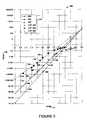
- FIG. 3is a graph of experimental and theoretical results for temperatures determined.
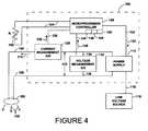
- FIG. 4is a block diagram of a circuit for determining an ambient temperature.
- FIG. 5 ais a block diagram of a circuit for determining an ambient temperature using conductors for powering the light emitting diode.
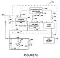
- FIG. 5 bis another block diagram of the circuit for determining an ambient temperature using conductors for powering the light emitting diode.
- FIG. 6is a diagrammatic illustration, in elevation, of a control system having a switch for controlling a light emitting diode mounted in a light fixture in a room.
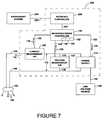
- FIG. 7is a block diagram of a control system having an interface for transferring data to a supervisory system.
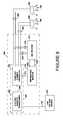
- FIG. 8is a block diagram of a control system for determining a temperature of more than one light emitting diode.
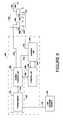
- FIG. 9is another block diagram of a control system for determining a temperature of more than one light emitting diode.
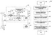
- FIG. 10is a flow diagram illustrating a method for determining a temperature of at least one light emitting diode.
- FIG. 11is a flow diagram illustrating a method for determining a temperature near at least one light emitting diode in a circuit.
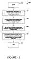
- FIG. 12is a flow diagram illustrating a method for electrically communicating with at least one LED assembly to control the LED assembly.
- FIG. 1illustrates one embodiment of a light emitting diode (LED) control system, indicated by the reference number 100 within a dashed line.
- Control system 100is electrically connected to an LED 102 using a first LED conductor 104 and a second LED conductor 106 .
- LED 102is operable to produce light, represented by arrows 108 , when the LED receives an operating current 110 through the LED conductors in a range of operating currents and receives an operating voltage 112 in a range of operating voltages across the LED conductors.
- control system 100includes a power supply 114 which is connected to a line power source 116 through line conductors 118 .
- the utility power sourceprovides an AC line voltage at a typical line voltage, such as 110 Volts RMS, to power supply 114 .
- Power supply 114converts the utility power to the operating voltage in the range of operating voltages and applies the operating voltage to the LED conductors.
- Power supply 114also converts the utility power to operating current 110 in the range of operating currents and applies the operating current to the LED conductors.
- a separate transformer(not shown in FIG. 1 ) can be used for transforming the line power from the line voltage source to a transformed power.
- the power supplyreceives the transformed power from the transformer and produces the operating current and operating voltage as discussed.
- Power supply 114can be controlled by a controller 120 through a control line 122 .
- Controller 120provides a current control signal 124 which controls the amount or magnitude of the operating current applied to the LED conductors.
- the amount of light produced by the LEDis directly related to the amount of operating current that the LED receives. Therefore, by controlling the operating current, the controller can control the amount of light produced by the LED.
- Controller 120can be connected to a current measurement analog to digital (A/D) converter 126 or other current sensor which detects the magnitude of the operating current and produces a current sensed signal 128 that is supplied to the controller through a current sensed signal line 130 .
- A/Danalog to digital
- the controllercan determine the present level of the operating current and can change current control signal 124 to adjust the magnitude of the operating current.
- the currentcan be determined by producing the current at a known magnitude.
- a voltage measurement A/D converter 132 or other voltage sensoris connected between the first and second LED conductors using voltage sensor conductors 134 and 136 .
- Converter 132detects the voltage across the LED conductors and produces a voltage sensed signal 138 on a voltage sensed signal line 140 .
- the voltage sensed signal lineis connected to controller 120 , which receives the voltage sensed signal 138 and can determine the operating voltage that is supplied to LED 102 . It should be noted that while LED 102 is presently discussed as a single LED, many of the concepts and embodiments are applicable to multiple LED's as well. Specific examples of multiple LED systems will also be discussed below.
- Controller 120can include a processor 142 , a clock 144 and a memory 146 along with software, not specifically shown, which enables the controller to determine the operating current and the operating voltage based on the current sensed signal 128 and the voltage sensed signal 138 , respectively.
- the softwarecan be configured to operate the controller as required in view of the overall disclosure. Controller 120 can also store values of the operating current and voltage in the memory along with the times at which the stored values occurred, among other things.
- the LEDis operable at an operating temperature which is at a safe level if it remains below a maximum temperature. If the temperature exceeds the maximum temperature then the LED can be subject to thermal damage which can reduce the lifetime of the LED or cause rapid failure of the LED. In some instances, the heat causes an internal resistance of the LED to decrease which, in turn, increases the amount of current that flows through the LED which increases the heat produced. Left unchecked, the LED enters a condition of thermal runaway where the heat caused by the increased current which is caused by the heat eventually causes the temperature of the LED to exceed the maximum temperature and the LED fails.
- control system 100can determine the temperature of the LED based on electrical measurements through the two LED conductors. This allows the control system to set the operating current to prevent the LED from over heating as well as allowing for the determination of the operating lifetime of the LED, among other things.
- a diode equivalent circuit 150is shown connected to first LED conductor 104 and second LED conductor 106 .
- LED 102can be represented by the diode equivalent circuit which includes a diode junction 152 , a series resistance 154 and a shunt resistance 156 .
- operating current 104can be determined by the following ideal diode equation:
- Iis the operating current flowing through the LED
- I ois a constant depending on the LED properties
- Vis a voltage applied across the diode junction of the LED
- E gis a value that is closely related to the optical band gap of the semiconductor at the diode junction referred to as the “effective” optical band gap
- Ais a constant known as the diode factor which is usually a value between 1 and 2
- kis Boltzmann's constant
- Tis the temperature of the semiconductor diode junction in degrees Kelvin.
- the effective shunt resistanceis a result of surface and junction imperfections while the series resistance results from sheet resistance of the semiconductor doped layers, contact resistance and the wires.
- the effective shunt resistanceis extremely high as the junction depletion width increases. This insulating layer allows for essentially no current flow through the reverse biased LED.
- a Zener diode(not shown) is usually placed across the diode to drain off current at voltages above about 5 volts.
- Equation 1describes the current, voltage and temperature operation of the LED to an acceptable level of accuracy within a range of operating voltages where the operating voltage is above where the shunt resistance dominates and below where the series resistance dominates. In one embodiment, this range is from about 1.5 V to about 2.5 V, however this range may be larger or smaller depending on characteristics of the LED.
- E gOne of the values needed to determine the temperature is the effective optical band gap value, E g .
- the effective optical band gapis nearly the same for all white LED's since most LED's use blue light to produce the white light, even when different semiconductor materials are used. In many white LED's, the blue or UV light is used to excite phosphor to produce white light in the white LED's. Applicant has empirically demonstrated with several commercial LED's that the effective optical band gap is 3.2 eV.
- the diode factor Ais taken to be 2, which is usually a good assumption for LED's for diodes where junction recombination dominates.
- the effective band gapcan also be determined for the LED by solving Equation 1 for E g if all of the other variables in Equation 1 are known.
- FIG. 3A comparison of experimental data with results obtained using Equation 1 is shown in a graph 160 in FIG. 3 .
- Graph 160shows a plot of a log of operating current 110 plotted against operating voltage 112 at three different experimental temperatures; 260 degrees Kelvin, 295 degrees Kelvin and 383 degrees Kelvin (hereinafter K).
- Kdegrees Kelvin
- a value of 5 ⁇ 10 2 Ampswas used in Equation 1 for I o to make the calculated data fit the experimental data.
- the experimental datawas obtained by immersing the LED in a temperature controlled mineral oil bath while the data was taken.
- a thermocouplewas welded to a metal slug of the LED to measure the temperature of the LED and oil bath and the operating current and operating voltage were measured.
- the experimental results for the log current vs. voltage points at 260 Kare shown by small circular dots, some of which are indicated by the reference number 162 , the temperature curve of theoretical results obtained using Equation 1 for the temperature of 260 K are represented by dashed line 164 .
- Data points for the experimental results of the current vs. voltage at 295 Kare shown as X's, some of which are indicated by the reference number 166 .
- Solid line 168is a temperature curve that shows the theoretical results obtained using Equation 1 with the 295 K temperature.
- the experimental results for current vs. voltage at 383 Kare shown by circular dots, some of which are indicated by the reference number 170 .
- a temperature curve of the theoretical results obtained using Equation 1 at 383 Kare shown by dashed line 172 .
- Key 174also shows which information is experimental and which was obtained using Equation 1 for subsequently generating the three linear plots.
- the temperature curvemoves to the left and the slope of the curve decreases. Therefore by determining a point on the graph of current and voltage of an LED, the temperature of the LED can be determined based on where the point falls on the graph. Also, by determining more than one point based on more than one current and voltage, the slope of the temperature curve can be determined which can then establish the temperature for the multiple points. Further, by using Equation 1, a given current and voltage can be used to determine a single temperature of the LED at a given time.
- Control system 100can determine the temperature of LED 102 through the two wire connection to the LED using the first and second LED conductors 104 and 106 .
- Operating current 110can be provided by power supply 114 at a known amplitude.
- Operating voltage 112can be determined by voltage measurement A/D converter 132 .
- controller 120can determine the operating temperature of LED 102 based on current flow and voltage across the LED conductors. This allows the temperature of the LED to be determined from a location that is remote from the LED without the need for additional wires to connect to the LED. This also provides an accurate determination of the actual temperature of the LED die itself, not the temperature of the atmosphere around the LED as provided by a thermal detection device that is located in the thermal pathway of the LED.
- controller 120controls power supply 114 to produce a pulse 111 of current that is superimposed on operating current 110 through the LED conductors.
- This current pulsecan be produced at a known magnitude or the current can be accurately measured with current measurement A/D converter 126 .
- Current pulse 111is shown in the present example as a negative pulse which lowers the operating current while still keeping the operating current positive, but other pulse shapes can also be used.
- the current pulsecauses voltage 112 to react with a corresponding voltage pulse 113 which can be measured using the voltage measurement A/D converter 132 .
- Voltage pulse 113is a temporary reduction in operating voltage that still maintains the forward bias across the LED. Controller 120 then uses the amplitudes of the current and voltage pulses to determine the temperature of the LED using Equation 1.
- a voltage pulsecan be used in place of the current pulse.
- the voltage pulsewould be applied to the LED conductors at an amplitude that is either known or sensed and the resulting current pulse can be measured using the current measurement A/D converter. It should be understood that measurements of current or voltage pulses can be accomplished in a number of different ways in view of the recognitions that have been brought to light herein.
- an average temperature of groups of LEDs that are arranged in series or parallelcan be determined based on one or more current pulses through the LEDs.
- the current pulsecan be an increase or a decrease in the operating current, and the current pulse can also be in the shape of a ramp, triangle wave or other shape that provides more than one current. In the case where the current pulse includes a shape such as the ramp, the current pulse will provide more than one different current amplitude which, in response, will cause the voltage to exhibit more than one different voltage amplitude. These multiple corresponding currents and voltages can then be used to determine the temperature either based on points on a graph, such as graph 160 , or based on a slope of a temperature curve. In one example, the current pulse can be used to put the corresponding sensed voltage in a voltage range, described above, between where the series resistance of the LED and the shunt resistance of the LED dominate.
- pulsescan also be used and the pulses can be produced at regular intervals, or based on the temperature determined or on other parameters.
- power suppliescan provide anomalies such as ripples in the current which can be used as the current pulse. Switching type power supplies are one example of these types of devices.
- the current pulsecan be sufficiently short in duration such that any change in light output by the LED caused by the pulse is not perceivable by humans. This avoids any perceived flickering of the light level that would not be desirable in a lighting system that is used at least partially for illumination for human perception.
- High persistence phosphorscan be used so that a longer pulse duration can be used. The longer pulse can improve the accuracy of the temperature determination by allowing for the use of a more accurate A/D converter which uses a longer sampling time and can average out random noises and other interference.
- control system 100can control the operating current to the LED so that the LED temperature is maintained at a safe operating temperature below which heat damage to the LED can occur.
- Controller 120can be programmed with the maximum safe operating temperature of the LED and can compare the determined temperature with the safe operating temperature. The controller can raise or lower the operating current until the LED operates at a desired operating temperature. The controller can also provide other control functions.
- the control systemcan also record the determined temperatures to a file in the memory along with the time of the temperature. In this way, the control system can keep a running tally of the operating temperature of the LED and time of operation of the LED to project the lifetime of the LED.
- the memorycan be non-volatile memory so that the system can remember the temperature of the LED in the event of a brief power failure. When power is restored, this allows the control system to resume operation of the LED by setting the operating current based at least partially on the stored operating temperature.
- Operating current and/or operating voltage or other parameterscan also be stored into memory for tracking other information regarding the LED. For instance, by tracking operating current, operating voltage and time, the control system can monitor power consumption of the LED. Overall operating time of the LED can be tracked by monitoring the time that operating current and/or operating voltage are applied to the LED.
- a control system 180includes a connection with a thermistor 182 .
- Thermistor 182is electrically connected to controller 120 with thermistor conductors 184 so that the controller can determine a thermistor temperature at the location of the thermistor by determining a resistance of the thermistor.
- thermistor 182is located remote from LED 102 but is in the same thermal environment as the LED. By being in the same environment, thermistor 182 and LED 102 are essentially at the same temperature prior to operation of the LED at startup or after the LED has had sufficient time to cool to the ambient temperature after operation.
- thermistor 182can be used to determine a temperature of the LED. This operation could be conducted after the LED and control system are installed where they are to be used, or could be conducted during a manufacturing process prior to installation.
- Thermistor 182can also be mounted near the LED and/or within the same enclosure as LED 102 , such as within a light fixture. In this case, the thermistor conductors would reach from the controller to the location of the thermistor near the LED. Also, this allows the control system to be in a different thermal environment from the LED and thermistor.
- a thermistor 186is electrically connected in parallel with LED 102 and is positioned in a thermal pathway to receive heat from the LED.
- Thermistor 186is chosen to have an effective resistance range that is lower than an effective resistance of the LED when reverse biased. At a reverse bias voltage, up to about ⁇ 5 Volts, the reverse bias resistance of the LED is extremely high.
- the thermistorcan also be chosen to have a forward voltage bias resistance that is much higher than an effective forward voltage resistance of the LED. As shown in FIG.
- a control system 188can apply a current pulse 189 to the LED conductors such that a reverse bias voltage pulse 191 is created and a reverse bias voltage 199 is seen across the LED.
- the current pulse 189causes a reverse drive current 193 in the LED conductors.
- One portion of the reverse drive currentflows through the LED as a leakage current 195 which does not cause the LED to produce light.
- Another portion of the reverse drive currentflows through the thermistor as a reverse thermistor current 197 .
- the leakage current flow through the LEDis insignificant compared with the reverse thermistor current flow through the thermistor and therefore the leakage current can be ignored while still gaining a reasonably accurate temperature measurement from the thermistor.
- the temperature of the thermistoris the same as the LED temperature. Connecting the thermistor in parallel with the LED allows the thermistor to be positioned with the LED and away from the control system while maintaining the advantage of only using the two LED conductors for powering the LED and for temperature determination.
- FIG. 5 bOperation of the LED to produce light is shown in FIG. 5 b where a forward drive current 201 is applied to the LED conductors.
- Forward drive current 201includes one portion which flows through the LED and is referred to as the forward operating current 203 and another portion that flows through the thermistor which is referred to as a forward thermistor current 205 .
- the forward drive currentproduces a forward operating voltage 207 across the LED.
- the controllerBy determining an ambient temperature of the LED, applying a current pulse to the LED, determining a magnitude of the current pulse and the resulting magnitude of voltage pulse, the controller has three variables; current, voltage and temperature, that can be used in Equation 1. Using the values determined for these variables, and supplying known or estimated values for other parameters, the controller can solve Equation 1 for any one of the remaining parameters. For instance, knowing the operating current, operating voltage, temperature, I o and the diode factor A, the controller can calculate the effective band gap E g . By knowing the other variables, the diode factor can be calculated. The thermistor temperature can also be used in a calibration procedure to increase the accuracy in later determining the temperature using the operating current and operating voltage. The thermistor can be included in the diode package along with the LED die and in some cases a zener diode.
- control system of the several embodiments disclosedcan be located remotely from the LED or within the same enclosure as the LED, such as within a light fixture.
- One or more components of the control systemcan also be arrange on one or more integrated circuits which can be included in a single LED package along with the LED die.
- FIG. 6One embodiment in which the control system is located remotely from the LEDs is shown in FIG. 6 .
- the control systemis included in a switch assembly 190 that is installed at a fixed location in a wall 192 .
- Switch assembly 190includes a switch 191 for controlling the application of power to LED 102 through LED conductors 104 and 106 .
- LED 102can be installed in a lighting fixture 194 that can be mounted in a fixed position in a ceiling 196 within a room 198 with wall 192 and switch assembly 190 .
- the switchcan be a line voltage switch in which case the line voltage is controlled by the switch before it is passed to the control system.
- the line voltageis connected to a control system 200 using line conductors 118 .
- Switch 191is connected using switch conductors 204 to controller 120 within the control system to control power to the LEDs through the control system.
- Switch assembly 190can have an on/off function and/or dimming capabilities through control by the controller.
- a display 206can be included and connected to the controller with a display conductor 202 to indicate the status of the switch and/or the LED to a user.
- the displaycan be one or more colored indicators or can be a screen type display.
- Switch assembly 190can be configured to fit within and connect to a conventional single-gang electrical box 210 such as those typically used for mounting a conventional single-pole line voltage switch in a wall.
- Control system 220includes an interface 222 for transferring data gathered by the control system to a supervisor system 224 .
- Datacan be transferred from controller 120 to interface 222 over an interface conductor 223 .
- the supervisor systemcan be a system that is used for building control and/or monitoring and can receive data gathered by multiple control systems controlling multiple LEDs at different locations. Information regarding power usage, temperature, operable lifetime of the LED and other useful information based on time, temperature, current and/or voltage can be transmitted between control system 220 and supervisor system 224 .
- Control system 220 and/or supervisor system 224can include displays for notifying users of the status of the LED.
- the supervisor systemcan provide control instructions to the control system to cause it to control light output.
- the interfacecan connect to the supervisor system using a cable 226 such as an Ethernet cable, over the line conductors 118 or can use wireless communications such as a ZigBeeTM or other type of wired or wireless communication to a building information system.
- Control system 250includes a power supply 251 with a transformer 252 that is connected to receive line power from line power source 116 through line power conductors 118 .
- Transformer 252transforms the line voltage, which is 115 Volts AC in the present case, to 12 Volts AC. Line voltage is typically over 100V AC, for the present embodiment.
- Power supply 251also includes a current controller 256 . The transformer is connected to current controller 256 using a power supply conductor 258 to supply the 12 Volt power to the current controller.
- Power supply 251is configured to use the 12 Volts AC to supply an operating current and operating voltage to multiple LEDs.
- the current controlleris connected to two different LEDs, LED 260 and LED 262 .
- LEDs 260 and 262can be separate LEDs in one fixture, can be separate LEDs in separate fixtures or each LED 260 and 262 can each represent multiple LEDs that are connected together and/or with other LEDs within a similar thermal environment in a series, parallel or series-parallel circuit arrangement.
- LED 260is connected to current controller 256 using LED conductors 264 and LED 262 is connected to current controller 256 using LED conductors 266 .
- Current controller 256powers LEDs 260 and 262 through the respective LED conductors.
- Control system 250also includes a temperature monitor 270 that is connected to the current controller using a control line 272 .
- Temperature monitor 270includes a processor as well as current and voltage A/D converters that are not specifically shown in this example. Temperature monitor 270 sends control signals over control line 272 to the current controller to set the operating current to each of the LEDs. Based on the known operating characteristics and limitations of the LEDs, a processor of the temperature monitor can regulate the operating current to the LEDs via controlling the DC current or pulsed DC current. That control may make use of user preferences to maintain constant light output and/or to maintain long life. Temperature monitor 270 can also control the current controller to produce current pulses for measurement purposes over each of the LED conductors.
- a multiplexer 274is connected to LED conductors 264 and 266 using multiplexer conductor lines 276 and 278 , respectively.
- Multiplexer 274is connected to the temperature monitor using a control line 280 and a signal line 282 .
- Temperature monitor 270controls the multiplexer through the control line to selectively receive signals from one or the other of LED conductors 264 or 266 through multiplexer conductor lines 276 or 278 .
- the multiplexerthen passes the selected signals to the temperature monitor through signal line 282 .
- the temperature monitordetermines the current and voltage on the selected LED conductor and calculates the corresponding temperature of the LED connected to the selected LED conductor.
- Temperature monitor 270can then control the current controller to adjust the operating current of the selected LED based on the temperature. This process can then be repeated for the LED that was not previously selected. In this way, each of the LEDs in the system can be monitored for temperature, current, voltage and power usage so long as they have a separate electrical connection to control system 250 .
- Control system 250can be included in a switch assembly with a switch, as previously discussed, and the switch assembly can be arranged for installation in a wall of a room to control LEDs supplying light to the room.
- Control system 250can also include an interface for communicating with a supervisory system as previously discussed. Using control system 250 with a supervisory system allows the supervisory system to monitor and/or control multiple LEDs on an individual basis.
- FIG. 9Another multiple LED arrangement is shown in FIG. 9 wherein a control system 300 is connected to two LEDs 302 and 304 that are electrically connected in series.
- the number of LEDs shown in FIG. 9is exemplary of a system with multiple LEDs.
- the LEDsconnect to the control system using LED conductors 310 and 312 .
- LEDs 302 and 304each include an integral heat sink 306 and 308 , respectively, that are electrically connected to the LED die.
- the heat sinksare electrically connected to an LED conductor 312 using conductors 314 and 316 .
- LED 302is connected to LED conductor 310 using a first power terminal and an LED conductor 320 connects a second power terminal of LED 302 to a first power terminal of LED 304 .
- a second power terminal of LED 304is connected to an earth ground using a ground conductor 322 .
- Control system 300includes a power supply 330 having a transformer 332 and a power controller 334 .
- Transformer 332receives line power from power source 116 through line power conductors 118 and transforms the line power from a higher voltage to a lower voltage which is transferred to the power controller through a power supply conductor 338 .
- Transformer 332can be electronic or electro-magnetic.
- Control system 300also includes a temperature monitor 340 which can have a microprocessor controller. Temperature monitor 340 is connected to the power controller using a control line 342 to pass control signals between the temperature monitor and the power controller.
- Power controller 334supplies power to the LEDs at an operating voltage and at an operating current controlled by the temperature monitor.
- a current A/D converter 344is connected to the temperature monitor using a control line 346 and a signal line 348 .
- each LEDeffectively has three terminals. Pulses from power controller 334 can be sensed at each LED using current A/D converter 344 through the conductors 314 and 316 as the pulse passes through each LED.
- Control system 300can also include a control switch and can be arranged to fit within the volume envelope of a typical single-gang junction box.
- Each of the LEDs or groups of LEDscan also include an electronic module with electronics that respond to an analog or digital signal command.
- the signal commandscan originate from a controller in a wall switch, or other location.
- Each LED modulecan respond to such commands individually back to the controller via the conductors 314 or 316 by producing a pulse which the controller can detect through current A/D 344 .
- the electronic modulecan also be arranged to periodically produce a pulse that is unique for each LED or group of LEDs.
- the electronic modulecan also be configured to divert all or a portion of the current flowing through conductor 310 to the conductors 314 or 316 and on to the current A/D.
- the controllercan record the current-voltage characteristics and determine a temperature for the LED connected to the module. The controller can then send a signal to have the module adjust current in the LED as required.
- Each of the LEDs or groups of LEDscan also have a passive or active filter tuned to a different frequency.
- the filtercan be used to address the LED individually.
- the pulsecan include a frequency component which allows the pulse to be received by a selected individual or group of LEDs to allow the temperature of the selected LED to be determined.
- the control system described hereincan be used as a ballast for LED lighting fixtures and much of the control system can be made in a single IC.
- the control systemallows the determination of the actual temperature of an LED, not an estimated temperature based on a temperature near the LED.
- the control systemcan operate using only the two wires normally connected to power the LED. By using centralized control and monitor of the LED temperatures cost for LED fixtures can be reduced over systems in which each fixture includes temperature monitoring and control.
- a method 500is shown in FIG. 10 for determining a temperature of at least one LED.
- Method 500begins at a start 502 and then proceeds to a step 504 where an operating current and operating voltage are provided to the LED through first and second LED conductors.
- step 504an operating current and operating voltage are provided to the LED through first and second LED conductors.
- step 506a current pulse is superimposed on the operating current to the LED through the first and second LED conductors. This results in a voltage pulse that is superimposed on the operating voltage.
- step 508the voltage pulse is sensed across the first and second LED conductors to determine a magnitude of the voltage pulse.
- Method 500then proceeds to step 510 where a current magnitude of the current pulse is determined.
- step 512an operating temperature of the LED is determined based on the current magnitude of the current pulse and the voltage magnitude of the voltage pulse.
- Method 500then ends at step 514 .
- Method 520begins at a start step 522 and then proceeds to a step 524 where a thermistor is arranged across the first and second LED conductors in parallel with the LED.
- the thermistorcan have an effective resistance range in which at least two different thermistor resistances of the thermistor correspond to at least two different thermistor temperatures of the thermistor.
- the thermistor resistances in the effective resistance rangeare lower than the reverse bias voltage resistance of the LED and are higher than the forward voltage resistance of the LED.
- step 526the effective resistance range is selected such that, when a forward drive current is applied to the LED conductors, one portion of the forward drive current which flows through the LED is the forward operating current and another portion of the forward drive current which flows through the thermistor is a forward thermistor current which is smaller than the forward operating current.
- step 526When the reverse bias voltage is supplied to the LED conductors, a reverse drive current flows through the LED conductors in an opposite direction than the forward drive current and one portion of the reverse drive current flows as a leakage current through the LED and which does not cause the LED to produce light and another portion of the reverse drive current flows through the thermistor as a reverse thermistor current which is larger than the leakage current.
- step 528the thermistor is positioned in a thermal pathway of the LED to receive heat produced by the LED during operation of the LED. The temperature of the thermistor is measurable by determining the thermistor resistance using the reverse thermistor current and the temperature of the thermistor is related to a temperature of the LED.
- step 530After step 528 , method 520 proceeds to step 530 where the method ends.
- a method 550 for electrically communicating with at least one LED assembly to control the LED assemblyis shown in FIG. 12 .
- Method 550begins at a start step 552 and then proceeds to a step 554 where a line power source is transformed.
- the line power sourcehaving a line voltage greater than 100 Volts AC and the line voltage is converted to a transformed power with a transformed voltage that is less than 50 Volts.
- step 554method 550 proceeds to step 556 where the transformed power is received and an operating power with at least the operating current in the range of operating currents and the operating voltage in the range of operating voltages is created.
- step 556is a step 558 where the operating current and operating voltage are selectively supplied to the LED assembly through the LED conductors to control light output of the LED assembly.
- step 560a temperature of the LED is determined through the LED conductors at least partially by determining a magnitude of current through the LED conductors and determining a magnitude of voltage across the LED conductors.
Landscapes
- Physics & Mathematics (AREA)
- General Physics & Mathematics (AREA)
- Circuit Arrangement For Electric Light Sources In General (AREA)
- Led Devices (AREA)
Abstract
Description
V=IRs+
Claims (23)
Priority Applications (3)
| Application Number | Priority Date | Filing Date | Title |
|---|---|---|---|
| US14/177,673US9161415B2 (en) | 2009-01-13 | 2014-02-11 | Method and device for remote sensing and control of LED lights |
| US14/737,052US9326346B2 (en) | 2009-01-13 | 2015-06-11 | Method and device for remote sensing and control of LED lights |
| US15/065,655US9560711B2 (en) | 2009-01-13 | 2016-03-09 | Method and device for remote sensing and control of LED lights |
Applications Claiming Priority (4)
| Application Number | Priority Date | Filing Date | Title |
|---|---|---|---|
| US14440809P | 2009-01-13 | 2009-01-13 | |
| US12/683,393US8358085B2 (en) | 2009-01-13 | 2010-01-06 | Method and device for remote sensing and control of LED lights |
| US13/718,366US8686666B2 (en) | 2009-01-13 | 2012-12-18 | Method and device for remote sensing and control of LED lights |
| US14/177,673US9161415B2 (en) | 2009-01-13 | 2014-02-11 | Method and device for remote sensing and control of LED lights |
Related Parent Applications (1)
| Application Number | Title | Priority Date | Filing Date |
|---|---|---|---|
| US13/718,366ContinuationUS8686666B2 (en) | 2009-01-13 | 2012-12-18 | Method and device for remote sensing and control of LED lights |
Related Child Applications (1)
| Application Number | Title | Priority Date | Filing Date |
|---|---|---|---|
| US14/737,052Continuation-In-PartUS9326346B2 (en) | 2009-01-13 | 2015-06-11 | Method and device for remote sensing and control of LED lights |
Publications (2)
| Publication Number | Publication Date |
|---|---|
| US20140217896A1 US20140217896A1 (en) | 2014-08-07 |
| US9161415B2true US9161415B2 (en) | 2015-10-13 |
Family
ID=42318568
Family Applications (3)
| Application Number | Title | Priority Date | Filing Date |
|---|---|---|---|
| US12/683,393Active2031-02-06US8358085B2 (en) | 2009-01-13 | 2010-01-06 | Method and device for remote sensing and control of LED lights |
| US13/718,366ActiveUS8686666B2 (en) | 2009-01-13 | 2012-12-18 | Method and device for remote sensing and control of LED lights |
| US14/177,673ActiveUS9161415B2 (en) | 2009-01-13 | 2014-02-11 | Method and device for remote sensing and control of LED lights |
Family Applications Before (2)
| Application Number | Title | Priority Date | Filing Date |
|---|---|---|---|
| US12/683,393Active2031-02-06US8358085B2 (en) | 2009-01-13 | 2010-01-06 | Method and device for remote sensing and control of LED lights |
| US13/718,366ActiveUS8686666B2 (en) | 2009-01-13 | 2012-12-18 | Method and device for remote sensing and control of LED lights |
Country Status (5)
| Country | Link |
|---|---|
| US (3) | US8358085B2 (en) |
| EP (1) | EP2380405B1 (en) |
| AU (1) | AU2010204851B2 (en) |
| CA (1) | CA2749472A1 (en) |
| WO (1) | WO2010083171A2 (en) |
Cited By (6)
| Publication number | Priority date | Publication date | Assignee | Title |
|---|---|---|---|---|
| US20160197733A1 (en)* | 2013-09-06 | 2016-07-07 | Philips Lighting Holding B.V. | Controller for power line coding and power line coding method |
| US10485062B2 (en) | 2009-11-17 | 2019-11-19 | Ledvance Llc | LED power-supply detection and control |
| US11071178B2 (en) | 2018-07-16 | 2021-07-20 | Jiaxing Super Lighting Electric Appliance Co., Ltd. | LED lighting system, apparatus, and dimming method |
| US11191136B2 (en) | 2018-07-16 | 2021-11-30 | Jiaxing Super Lighting Electric Appliance Co., Ltd. | LED lighting system, apparatus, and dimming method |
| US20220295611A1 (en)* | 2019-07-09 | 2022-09-15 | Signify Holding B.V. | Method of controlling a lighting arrangement, a lighting control circuit and a lighting system |
| US12089316B1 (en)* | 2023-12-14 | 2024-09-10 | Jiangmen Jinglian Technology Development Co., Ltd. | PLC signal control lamp system with adaptive power supply |
Families Citing this family (61)
| Publication number | Priority date | Publication date | Assignee | Title |
|---|---|---|---|---|
| US8111001B2 (en) | 2007-07-17 | 2012-02-07 | Cree, Inc. | LED with integrated constant current driver |
| TWI355484B (en)* | 2007-12-14 | 2012-01-01 | Ind Tech Res Inst | Apparatus and method for measuring character and c |
| DE102008057347A1 (en)* | 2008-11-14 | 2010-05-20 | Osram Opto Semiconductors Gmbh | Optoelectronic device |
| US8232742B2 (en) | 2008-11-27 | 2012-07-31 | Arkalumen Inc. | Method, apparatus and computer-readable media for controlling lighting devices |
| US8358085B2 (en) | 2009-01-13 | 2013-01-22 | Terralux, Inc. | Method and device for remote sensing and control of LED lights |
| US9326346B2 (en) | 2009-01-13 | 2016-04-26 | Terralux, Inc. | Method and device for remote sensing and control of LED lights |
| JP5807880B2 (en)* | 2009-05-12 | 2015-11-10 | コーニンクレッカ フィリップス エヌ ヴェKoninklijke Philips N.V. | Intelligent dimmer for managing lighting load |
| TW201043098A (en)* | 2009-05-18 | 2010-12-01 | Young Optics Inc | Light-emitting apparatus and control method thereof |
| US9881532B2 (en) | 2010-02-04 | 2018-01-30 | Ignis Innovation Inc. | System and method for extracting correlation curves for an organic light emitting device |
| US10089921B2 (en) | 2010-02-04 | 2018-10-02 | Ignis Innovation Inc. | System and methods for extracting correlation curves for an organic light emitting device |
| US20140313111A1 (en) | 2010-02-04 | 2014-10-23 | Ignis Innovation Inc. | System and methods for extracting correlation curves for an organic light emitting device |
| US9086435B2 (en) | 2011-05-10 | 2015-07-21 | Arkalumen Inc. | Circuits for sensing current levels within a lighting apparatus incorporating a voltage converter |
| US9089024B2 (en) | 2010-05-11 | 2015-07-21 | Arkalumen Inc. | Methods and apparatus for changing a DC supply voltage applied to a lighting circuit |
| US8564214B2 (en) | 2010-05-11 | 2013-10-22 | Arkalumen Inc. | Circuits for sensing current levels within lighting apparatus |
| US8340941B2 (en)* | 2010-06-04 | 2012-12-25 | Tyco Electronics Corporation | Temperature measurement system for a light emitting diode (LED) assembly |
| MX346857B (en) | 2010-06-18 | 2017-04-03 | Xicato Inc | PHOTOEMISOR DIODE LIGHTING MODULE WITH INTEGRATED DIAGNOSIS. |
| US8536788B2 (en)* | 2010-08-06 | 2013-09-17 | Osram Sylvania Inc. | Thermal control of solid state light sources by variable series impedance |
| CA2810026A1 (en) | 2010-09-16 | 2012-03-22 | Terralux, Inc. | Communication with lighting units over a power bus |
| US9596738B2 (en) | 2010-09-16 | 2017-03-14 | Terralux, Inc. | Communication with lighting units over a power bus |
| CN103201554A (en) | 2010-11-10 | 2013-07-10 | 特锐拉克斯有限公司 | Recessed Ceiling Lighting Retrofit Lighting |
| RU2013131244A (en)* | 2010-12-09 | 2015-01-20 | Конинклейке Филипс Электроникс Н.В. | ELECTROLUMINESCENT DEVICE WITH ADJUSTABLE COLOR POINT |
| US9192009B2 (en) | 2011-02-14 | 2015-11-17 | Arkalumen Inc. | Lighting apparatus and method for detecting reflected light from local objects |
| US8941308B2 (en) | 2011-03-16 | 2015-01-27 | Arkalumen Inc. | Lighting apparatus and methods for controlling lighting apparatus using ambient light levels |
| US8939604B2 (en) | 2011-03-25 | 2015-01-27 | Arkalumen Inc. | Modular LED strip lighting apparatus |
| US8573841B2 (en)* | 2011-04-08 | 2013-11-05 | Advanced Micro Devices, Inc. | On-chip temperature sensor |
| US9060400B2 (en) | 2011-07-12 | 2015-06-16 | Arkalumen Inc. | Control apparatus incorporating a voltage converter for controlling lighting apparatus |
| US9081125B2 (en) | 2011-08-08 | 2015-07-14 | Quarkstar Llc | Illumination devices including multiple light emitting elements |
| CN103858244B (en) | 2011-08-08 | 2018-08-10 | 夸克星有限责任公司 | Lighting device comprising a plurality of light emitting elements |
| US20140239809A1 (en)* | 2011-08-18 | 2014-08-28 | Lynk Labs, Inc. | Devices and systems having ac led circuits and methods of driving the same |
| WO2013090904A1 (en) | 2011-12-16 | 2013-06-20 | Terralux, Inc. | System and methods of applying bleed circuits in led lamps |
| US8643285B2 (en) | 2012-01-14 | 2014-02-04 | Yang Pan | Constant temperature light emitting diode lighting system |
| US9293447B2 (en)* | 2012-01-19 | 2016-03-22 | Epistar Corporation | LED thermal protection structures |
| DE102012003162A1 (en)* | 2012-02-19 | 2013-08-22 | Hans-Wolfgang Diesing | Temperature-controlled driver concept for LED lamps |
| US9271373B2 (en)* | 2012-06-08 | 2016-02-23 | Dialight Corporation | Remotely distributed power network for an LED lighting system |
| CN102818651B (en)* | 2012-07-31 | 2014-07-02 | 广东威创视讯科技股份有限公司 | Detection method and detection circuit of LED (Light Emitting Diode) light source temperature |
| CA2832128A1 (en)* | 2012-11-02 | 2014-05-02 | RAB Lighting Inc. | Dimming for constant current led driver circuit |
| US9265119B2 (en) | 2013-06-17 | 2016-02-16 | Terralux, Inc. | Systems and methods for providing thermal fold-back to LED lights |
| US9596737B2 (en) | 2013-07-02 | 2017-03-14 | Xicato, Inc. | Multi-port LED-based lighting communications gateway |
| US9591726B2 (en) | 2013-07-02 | 2017-03-07 | Xicato, Inc. | LED-based lighting control network communication |
| US10078020B2 (en) | 2013-08-23 | 2018-09-18 | Whirlpool Corporation | Methods and apparatus to determine home appliance cabinet temperature using a light emitting diode (LED) |
| JP2015103666A (en)* | 2013-11-25 | 2015-06-04 | セイコーエプソン株式会社 | Light emitting device and image display device |
| US9204524B2 (en) | 2014-03-10 | 2015-12-01 | Dynotron, Inc. | Variable lumen output and color spectrum for LED lighting |
| US9907148B2 (en) | 2014-03-10 | 2018-02-27 | Dynotron, Inc. | LED lighting system having at least one heat sink and a power adjustment module for modifying current flowing through the LEDs |
| US10598320B2 (en)* | 2014-07-02 | 2020-03-24 | Ledvance Llc | Integral cooling for LED lighting source |
| US10098199B2 (en)* | 2014-08-13 | 2018-10-09 | Lumenetix, Inc. | Architectures for light emitting diode (LED) lighting systems |
| RU2711242C2 (en)* | 2015-04-14 | 2020-01-15 | Филипс Лайтинг Холдинг Б.В. | Light system and method of estimating end of service life of at least one lamp |
| US9992836B2 (en) | 2015-05-05 | 2018-06-05 | Arkawmen Inc. | Method, system and apparatus for activating a lighting module using a buffer load module |
| US10225904B2 (en) | 2015-05-05 | 2019-03-05 | Arkalumen, Inc. | Method and apparatus for controlling a lighting module based on a constant current level from a power source |
| US9775211B2 (en) | 2015-05-05 | 2017-09-26 | Arkalumen Inc. | Circuit and apparatus for controlling a constant current DC driver output |
| US10568180B2 (en) | 2015-05-05 | 2020-02-18 | Arkalumen Inc. | Method and apparatus for controlling a lighting module having a plurality of LED groups |
| US9992829B2 (en) | 2015-05-05 | 2018-06-05 | Arkalumen Inc. | Control apparatus and system for coupling a lighting module to a constant current DC driver |
| CA2891165A1 (en) | 2015-05-14 | 2016-11-14 | Peter E. Freill | Lighting assembly, system and installation method for hardscapes and steps |
| CN105468332B (en)* | 2015-11-20 | 2017-11-28 | 中国科学技术大学 | A kind of instant true random signal generator of data processing postposition type |
| DE102016202501B4 (en)* | 2016-02-18 | 2022-03-17 | Continental Automotive Gmbh | Method for determining a calibration current pulse |
| TWI614485B (en)* | 2016-12-01 | 2018-02-11 | 新唐科技股份有限公司 | Temperature sensing apparatus and temperature sensing method thereof |
| US20210074880A1 (en)* | 2018-12-18 | 2021-03-11 | Bolb Inc. | Light-output-power self-awareness light-emitting device |
| US10796977B2 (en)* | 2019-03-04 | 2020-10-06 | Intel Corporation | Method and apparatus to control temperature of a semiconductor die in a computer system |
| EP4388298A1 (en)* | 2021-08-20 | 2024-06-26 | Cepheid | Diagnostic assay instrument comprising stabilized led illumination unit and corresponding method |
| CN113692093B (en)* | 2021-08-23 | 2024-01-26 | 华域视觉科技(上海)有限公司 | Light emitting module control method, electronic equipment, light emitting module, car lamp and vehicle |
| US20240044724A1 (en)* | 2022-08-02 | 2024-02-08 | Borgwarner Inc. | Thermistor self-heating compensation |
| TWI849621B (en)* | 2022-12-14 | 2024-07-21 | 松翰科技股份有限公司 | Thermal sensing method |
Citations (231)
| Publication number | Priority date | Publication date | Assignee | Title |
|---|---|---|---|---|
| US4085403A (en) | 1975-01-30 | 1978-04-18 | Robert Bosch Gmbh | Combined on-board remote control energy supply distribution and signaling system, particularly for automotive vehicles |
| JPS57133685U (en) | 1981-02-10 | 1982-08-20 | ||
| US4529949A (en) | 1982-02-11 | 1985-07-16 | Nederlandse Centrale Organisatie Voor Toegepast-Natuurwetenschappelijk Onderzoek | Bias control circuit for light-emitting diode having temperature compensation |
| JPS6166564A (en) | 1984-09-07 | 1986-04-05 | Hitachi Ltd | power supply |
| US4633161A (en) | 1984-08-15 | 1986-12-30 | Michael Callahan | Improved inductorless phase control dimmer power stage with semiconductor controlled voltage rise time |
| WO1990010238A3 (en) | 1989-02-21 | 1990-10-18 | Metricor Inc | Thermo-optical current sensor and thermo-optical current sensing systems |
| US5291607A (en) | 1990-09-05 | 1994-03-01 | Motorola, Inc. | Microprocessor having environmental sensing capability |
| US5334916A (en)* | 1991-05-27 | 1994-08-02 | Mitsubishi Kasei Corporation | Apparatus and method for LED emission spectrum control |
| US5401099A (en) | 1992-02-10 | 1995-03-28 | Sumitomo Electric Industries, Ltd. | Method of measuring junction temperature |
| EP0657697A1 (en) | 1993-12-13 | 1995-06-14 | Hobart Corporation | Microprocessor-based temperature control circuit |
| US5485576A (en) | 1994-01-28 | 1996-01-16 | Fee; Brendan | Chassis fault tolerant system management bus architecture for a networking |
| US5506490A (en) | 1993-11-09 | 1996-04-09 | Motorola, Inc. | Method and apparatus for determining external power supply type |
| US5546041A (en) | 1993-08-05 | 1996-08-13 | Massachusetts Institute Of Technology | Feedback sensor circuit |
| EP0492117B1 (en) | 1990-12-24 | 1996-10-23 | Motorola, Inc. | Current source with adjustable temperature variation |
| US5606510A (en) | 1991-12-13 | 1997-02-25 | The Dow Chemical Company | High speed power analyzer |
| US5661645A (en) | 1996-06-27 | 1997-08-26 | Hochstein; Peter A. | Power supply for light emitting diode array |
| US5691605A (en) | 1995-03-31 | 1997-11-25 | Philips Electronics North America | Electronic ballast with interface circuitry for multiple dimming inputs |
| US5781040A (en) | 1996-10-31 | 1998-07-14 | Hewlett-Packard Company | Transformer isolated driver for power transistor using frequency switching as the control signal |
| US5783909A (en) | 1997-01-10 | 1998-07-21 | Relume Corporation | Maintaining LED luminous intensity |
| WO1999000650A1 (en) | 1997-06-30 | 1999-01-07 | Maxim Integrated Products, Inc. | Temperature measurement with interleaved bi-level current on a diode and bi-level current source therefor |
| US5925990A (en) | 1997-12-19 | 1999-07-20 | Energy Savings, Inc. | Microprocessor controlled electronic ballast |
| US5942860A (en) | 1997-09-16 | 1999-08-24 | Philips Electronics North America Corporation | Electronic ballast for a high intensity discharge lamp with automatic acoustic resonance avoidance |
| US6069457A (en) | 1998-01-20 | 2000-05-30 | Lumion University | Method and apparatus for controlling lights and other devices |
| WO2000017728A9 (en) | 1998-09-22 | 2000-11-16 | U1 Inc | Computer controlled ac electrical terminations and network |
| US6153985A (en) | 1999-07-09 | 2000-11-28 | Dialight Corporation | LED driving circuitry with light intensity feedback to control output light intensity of an LED |
| GB2335334B (en) | 1998-03-13 | 2001-03-28 | And Software Ltd | Apparatus for and method of transmitting and receiving data over a low voltage power distribution system |
| US6313589B1 (en)* | 1999-11-16 | 2001-11-06 | Tokiwa Dengyo Co., Ltd. | Power supply circuit for traffic signal lights utilizing LEDs |
| US6332710B1 (en) | 2000-07-24 | 2001-12-25 | National Semiconductor Corporation | Multi-channel remote diode temperature sensor |
| US6351079B1 (en) | 1999-08-19 | 2002-02-26 | Schott Fibre Optics (Uk) Limited | Lighting control device |
| EP0923274B1 (en) | 1997-12-10 | 2002-04-03 | Siemens Aktiengesellschaft | Universal dimmer and process for dimming |
| US20020048177A1 (en) | 2000-09-06 | 2002-04-25 | Rahm Peter R. | Apparatus and method for adjusting the color temperature of white semiconductor light emitters |
| US6382812B1 (en) | 2001-02-13 | 2002-05-07 | Min Hsun Hsu | Decorative light string |
| US6429598B1 (en) | 2000-11-24 | 2002-08-06 | R. John Haley | Transformer and control units for ac control |
| US6459257B1 (en) | 1997-09-01 | 2002-10-01 | Siemens Aktiengesellschaft | Measuring system for measuring power and/or power factors at at least one measuring point in an a.c. voltage network |
| EP1271799A1 (en) | 2001-06-28 | 2003-01-02 | "VLAAMSE INSTELLING VOOR TECHNOLOGISCH ONDERZOEK", afgekort "V.I.T.O." | Method and devices for controlling loads on an electrical power supply |
| US20030015973A1 (en) | 2001-07-18 | 2003-01-23 | Kevin Ovens | Solid state traffic light with predictive failure analysis |
| US6515437B1 (en) | 1997-06-16 | 2003-02-04 | Lightech Electronics Industries Ltd. | Power supply for hybrid illumination system |
| US20030052658A1 (en) | 1995-01-11 | 2003-03-20 | Baretich David F. | Method and apparatus for electronic power control |
| EP1313353A1 (en) | 2001-11-19 | 2003-05-21 | Nokia Corporation | Method and device for operating a light emitting diode |
| JP2003188415A (en) | 2001-12-18 | 2003-07-04 | Asahi Matsushita Electric Works Ltd | LED lighting device |
| JP2003317979A (en) | 2003-05-20 | 2003-11-07 | Tokiwa Dengyo Kk | Power circuit |
| US6693394B1 (en) | 2002-01-25 | 2004-02-17 | Yazaki North America, Inc. | Brightness compensation for LED lighting based on ambient temperature |
| US6713974B2 (en) | 2002-01-10 | 2004-03-30 | Lightech Electronic Industries Ltd. | Lamp transformer for use with an electronic dimmer and method for use thereof for reducing acoustic noise |
| US6762629B2 (en) | 2002-07-26 | 2004-07-13 | Intel Corporation | VCC adaptive dynamically variable frequency clock system for high performance low power microprocessors |
| WO2004075606A1 (en) | 2003-02-20 | 2004-09-02 | Gelcore Llc | Module for powering and monitoring light-emitting diodes |
| JP2004296205A (en) | 2003-03-26 | 2004-10-21 | Matsushita Electric Works Ltd | LED dimming lighting device and lighting equipment |
| US6842668B2 (en) | 2001-09-06 | 2005-01-11 | Genlyte Thomas Group Llc | Remotely accessible power controller for building lighting |
| US20050057187A1 (en) | 2003-09-12 | 2005-03-17 | Technology Assessment Group Inc. | Universal light emitting illumination device and method |
| US20050057184A1 (en) | 2003-08-25 | 2005-03-17 | Tdk Corporation | Method and apparatus for managing temperature of light emitting element, and lighting apparatus |
| US6870325B2 (en) | 2002-02-22 | 2005-03-22 | Oxley Developments Company Limited | Led drive circuit and method |
| US20050062481A1 (en) | 2003-09-19 | 2005-03-24 | Thomas Vaughn | Wayside LED signal for railroad and transit applications |
| US6930737B2 (en) | 2001-01-16 | 2005-08-16 | Visteon Global Technologies, Inc. | LED backlighting system |
| WO2005081591A1 (en) | 2004-02-20 | 2005-09-01 | Koninklijke Philips Electronics N.V. | Electronic ballast with frequency detection |
| US20050237005A1 (en) | 2004-04-23 | 2005-10-27 | Lighting Science Group Corporation | Electronic light generating element light bulb |
| US20060038661A1 (en) | 2004-05-29 | 2006-02-23 | Daimlerchrysler Ag | Data transfer on a current supply line |
| US7029145B2 (en) | 2001-03-19 | 2006-04-18 | Integrated Power Components, Inc. | Low voltage decorative light string including power supply |
| US7034507B2 (en) | 2003-07-03 | 2006-04-25 | Micron Technology, Inc. | Temperature sensing device in an integrated circuit |
| DE19725710B4 (en) | 1996-07-01 | 2006-05-04 | Beat Larcher | Method and device for power and data transmission on common lines |
| US7049765B1 (en) | 2003-04-11 | 2006-05-23 | Tremaine Sr John M | Transformer for dimmer switch or on/off switch and method of use |
| WO2006058418A1 (en) | 2004-11-30 | 2006-06-08 | Brilliant Lighting Products Inc. | Multiple dimmer lighting system |
| US20060119288A1 (en) | 2004-12-06 | 2006-06-08 | Ayala Vicente A | Automatic light dimmer for electronic and magnetic ballasts (fluorescent or HID) |
| US20060125773A1 (en) | 2004-11-19 | 2006-06-15 | Sony Corporation | Backlight device, method of driving backlight and liquid crystal display apparatus |
| US20060152204A1 (en) | 2004-12-03 | 2006-07-13 | Dragan Maksimovic | Determining dead times in switched-mode DC-DC converters |
| US20060214876A1 (en) | 2005-03-23 | 2006-09-28 | Sony Ericsson Mobile Communications Ab | Electronic device having a light bus for controlling light emitting elements |
| US7119498B2 (en) | 2003-12-29 | 2006-10-10 | Texas Instruments Incorporated | Current control device for driving LED devices |
| US7126290B2 (en) | 2004-02-02 | 2006-10-24 | Radiant Power Corp. | Light dimmer for LED and incandescent lamps |
| US20060238169A1 (en) | 2005-04-22 | 2006-10-26 | William Baker | Temperature controlled current regulator |
| US20060237636A1 (en) | 2003-06-23 | 2006-10-26 | Advanced Optical Technologies, Llc | Integrating chamber LED lighting with pulse amplitude modulation to set color and/or intensity of output |
| US20060273741A1 (en) | 2005-06-06 | 2006-12-07 | Color Kinetics Incorporated | Methods and apparatus for implementing power cycle control of lighting devices based on network protocols |
| US7150561B1 (en) | 2004-09-16 | 2006-12-19 | National Semiconductor Corporation | Zero temperature coefficient (TC) current source for diode measurement |
| US20070040518A1 (en) | 2004-08-09 | 2007-02-22 | Dialight Corporation | Intelligent drive circuit for a light emitting diode (LED) light engine |
| US20070040512A1 (en) | 2005-08-17 | 2007-02-22 | Tir Systems Ltd. | Digitally controlled luminaire system |
| US7186000B2 (en) | 1998-03-19 | 2007-03-06 | Lebens Gary A | Method and apparatus for a variable intensity pulsed L.E.D. light |
| US20070057902A1 (en) | 2005-09-09 | 2007-03-15 | Samsung Electro-Mechanics Co., Ltd. | Circuit for controlling LED with temperature compensation |
| US7196481B2 (en) | 2003-09-30 | 2007-03-27 | Oxley Developments Company Limited | Method and drive circuit for controlling LEDs |
| US20070069656A1 (en) | 2005-09-26 | 2007-03-29 | Tsung-Jung Huang | Multifunctional light |
| US7204638B2 (en) | 2005-05-23 | 2007-04-17 | Etron Technology, Inc. | Precise temperature sensor with smart programmable calibration |
| KR20070053816A (en) | 2004-09-23 | 2007-05-25 | 코닌클리즈케 필립스 일렉트로닉스 엔.브이. | Light emitting element and manufacturing method thereof |
| US20070121324A1 (en) | 2003-02-13 | 2007-05-31 | Shoichi Nakano | Temperature adjusting device for an led light source |
| US7233258B1 (en) | 2004-04-13 | 2007-06-19 | Gelcore Llc | LED matrix current control |
| US7242150B2 (en) | 2005-05-12 | 2007-07-10 | Lutron Electronics Co., Inc. | Dimmer having a power supply monitoring circuit |
| US7245090B2 (en) | 2005-11-08 | 2007-07-17 | System General Corporation | Switching LED driver with temperature compensation to program LED current |
| US7245089B2 (en) | 2005-11-03 | 2007-07-17 | System General Corporation | Switching LED driver |
| CN2924996Y (en) | 2005-11-13 | 2007-07-18 | 曾祥云 | A low-cost high-performance LED lighting circuit |
| US7262559B2 (en) | 2002-12-19 | 2007-08-28 | Koninklijke Philips Electronics N.V. | LEDS driver |
| US7286123B2 (en) | 2005-12-13 | 2007-10-23 | System General Corp. | LED driver circuit having temperature compensation |
| US20070273290A1 (en) | 2004-11-29 | 2007-11-29 | Ian Ashdown | Integrated Modular Light Unit |
| US20070285031A1 (en) | 2004-09-21 | 2007-12-13 | Exclara Inc. | System and Method for Driving LED |
| US20070291483A1 (en) | 2001-05-30 | 2007-12-20 | Color Kinetics Incorporated | Controlled lighting methods and apparatus |
| WO2007147573A1 (en) | 2006-06-20 | 2007-12-27 | Arnold & Richter Cine Technik Gmbh & Co. Betriebs Kg | Method and device for driving light-emitting diodes of an illumination device |
| US20080018261A1 (en) | 2006-05-01 | 2008-01-24 | Kastner Mark A | LED power supply with options for dimming |
| US7322718B2 (en) | 2003-01-27 | 2008-01-29 | Matsushita Electric Industrial Co., Ltd. | Multichip LED lighting device |
| US7336434B2 (en) | 2005-07-18 | 2008-02-26 | Hitachi Global Storage Technologies Netherlands B.V. | Predictive failure analysis of thermal flying height control system and method |
| US20080062070A1 (en) | 2006-09-13 | 2008-03-13 | Honeywell International Inc. | Led brightness compensation system and method |
| US7344279B2 (en) | 2003-12-11 | 2008-03-18 | Philips Solid-State Lighting Solutions, Inc. | Thermal management methods and apparatus for lighting devices |
| US7358679B2 (en) | 2002-05-09 | 2008-04-15 | Philips Solid-State Lighting Solutions, Inc. | Dimmable LED-based MR16 lighting apparatus and methods |
| US20080088557A1 (en) | 2006-10-16 | 2008-04-17 | Samsung Electronics Co., Ltd. | Display apparatus and control method thereof |
| US20080111505A1 (en) | 2006-11-13 | 2008-05-15 | Polytronics Technology Corporation | Light emitting diode apparatus |
| US20080122422A1 (en) | 2004-06-04 | 2008-05-29 | Iwatt Inc. | Parallel Current Mode Control Using a Direct Duty Cycle Algorithm with Low Computational Requirements to Perform Power Factor Correction |
| US20080136334A1 (en) | 2006-12-12 | 2008-06-12 | Robinson Shane P | System and method for controlling lighting |
| US20080150442A1 (en) | 2006-12-22 | 2008-06-26 | Infineon Technologies Austria Ag | Method for operating a fluorescent lamp |
| US20080151965A1 (en) | 2006-12-22 | 2008-06-26 | Samsung Electronics Co., Ltd. | Display apparatus and color temperature control method thereof |
| JP2008172999A (en) | 2006-12-13 | 2008-07-24 | Canon Inc | Switching power supply |
| US20080180414A1 (en) | 2007-01-30 | 2008-07-31 | Kai Ming Fung | Method and apparatus for controlling light emitting diode |
| WO2008096249A2 (en) | 2007-02-07 | 2008-08-14 | Melexis Nv | Led driver |
| US20080198613A1 (en) | 2007-02-15 | 2008-08-21 | William Cruickshank | LED driver touch switch circuit |
| EP1701589B1 (en) | 2005-03-08 | 2008-08-27 | Sony Ericsson Mobile Communications AB | Electric circuit and method for monitoring a temperature of a light emitting diode |
| US20080204884A1 (en) | 2005-07-08 | 2008-08-28 | Min-Jun Jang | Integrating Sphere Having Means For Temperature Control |
| US20080203992A1 (en) | 2007-02-23 | 2008-08-28 | Jaber Abu Qahouq | Adaptive controller with mode tracking and parametric estimation for digital power converters |
| US20080215279A1 (en) | 2006-12-11 | 2008-09-04 | Tir Technology Lp | Luminaire control system and method |
| US7423750B2 (en) | 2001-11-29 | 2008-09-09 | Applera Corporation | Configurations, systems, and methods for optical scanning with at least one first relative angular motion and at least one second angular motion or at least one linear motion |
| US20080224633A1 (en) | 2007-03-12 | 2008-09-18 | Cirrus Logic, Inc. | Lighting System with Lighting Dimmer Output Mapping |
| US20080231198A1 (en) | 2007-03-23 | 2008-09-25 | Zarr Richard F | Circuit for driving and monitoring an LED |
| JP2008224136A (en) | 2007-03-13 | 2008-09-25 | Matsushita Electric Ind Co Ltd | Control device for fan filter unit |
| US7429129B2 (en) | 2005-02-28 | 2008-09-30 | Standard Microsystems Corporation | Proportional settling time adjustment for diode voltage and temperature measurements dependent on forced level current |
| US20080238340A1 (en) | 2007-03-26 | 2008-10-02 | Shun Kei Mars Leung | Method and apparatus for setting operating current of light emitting semiconductor element |
| US20080258636A1 (en) | 2007-04-19 | 2008-10-23 | Au Optronics Corporation | Led driver with current sink control and applications of the same g |
| US20080287742A1 (en) | 2007-04-17 | 2008-11-20 | Gyrus Acmi, Inc. | Light source power based on predetermined sensed condition |
| US20080319690A1 (en) | 2007-06-20 | 2008-12-25 | Usa As Represented By The Administrator Of The National Aeronautics & Space Administration | Forward Voltage Short-Pulse Technique for Measuring High Power Laser Diode Array Junction Temperature |
| US20090021955A1 (en) | 2007-07-17 | 2009-01-22 | I/O Controls Corporation | Control network for led-based lighting system in a transit vehicle |
| US20090021178A1 (en) | 2004-07-12 | 2009-01-22 | Norimasa Furukawa | Apparatus and method for driving backlight unit |
| US7486030B1 (en) | 2007-10-18 | 2009-02-03 | Pwi, Inc. | Universal input voltage device |
| US20090033612A1 (en) | 2007-07-31 | 2009-02-05 | Roberts John K | Correction of temperature induced color drift in solid state lighting displays |
| US7492108B2 (en) | 2005-08-11 | 2009-02-17 | Texas Instruments Incorporated | System and method for driving light-emitting diodes (LEDs) |
| US7504781B2 (en)* | 2004-10-22 | 2009-03-17 | Koninklijke Philips, N.V. | Method for driving a LED based lighting device |
| US7507001B2 (en) | 2002-11-19 | 2009-03-24 | Denovo Lighting, Llc | Retrofit LED lamp for fluorescent fixtures without ballast |
| US20090097244A1 (en) | 2007-10-12 | 2009-04-16 | Foxconn Technology Co., Ltd. | Led lamp with remote control device |
| JP2009083590A (en) | 2007-09-28 | 2009-04-23 | Toyoda Gosei Co Ltd | Vehicle-mounted light emitting diode lighting device |
| WO2009055821A1 (en) | 2007-10-26 | 2009-04-30 | Lighting Science Group Corporation | High efficiency light source with integrated ballast |
| US7546473B2 (en) | 2005-06-30 | 2009-06-09 | Lutron Electronics Co., Inc. | Dimmer having a microprocessor-controlled power supply |
| US20090146584A1 (en) | 2007-12-06 | 2009-06-11 | Samsung Electronics Co., Ltd. | Backlight assembly, display apparatus having the backlight assembly and method of preventing a current controller of the backlight assembly from being shut down |
| US20090154525A1 (en) | 2007-12-14 | 2009-06-18 | Industrial Technology Research Institute | Apparatus and method for measuring characteristic and chip temperature of led |
| EP2073607A1 (en) | 2007-12-19 | 2009-06-24 | Data Display GmbH | LED-controller for optimizing LED lifetime |
| WO2009079944A1 (en) | 2007-12-18 | 2009-07-02 | Shine Glory Enterprise Limited | Adaptive fluorescent lamp driver circuit |
| US20090167203A1 (en) | 2007-12-28 | 2009-07-02 | Mark Cobb Dahlman | AC-powered, microprocessor-based, dimming LED power supply |
| US7556423B2 (en) | 2007-01-08 | 2009-07-07 | Microchip Technology Incorporated | Temperature sensor bow compensation |
| US20090179848A1 (en) | 2008-01-10 | 2009-07-16 | Honeywell International, Inc. | Method and system for improving dimming performance in a field sequential color display device |
| US20090179574A1 (en) | 2008-01-16 | 2009-07-16 | Hsiu-Hui Chang | Backlight module of light emitting diode |
| US20090212736A1 (en) | 2008-02-22 | 2009-08-27 | Access Business Group International Llc | Inductive power supply system with battery type detection |
| US20090251059A1 (en) | 2008-04-04 | 2009-10-08 | Lemnis Lighting Patent Holding B.V. | Dimmer triggering circuit, dimmer system and dimmable device |
| US7605550B2 (en) | 2006-07-17 | 2009-10-20 | Microsemi Corp.—Analog Mixed Signal Group Ltd. | Controlled bleeder for power supply |
| US20090267523A1 (en) | 2008-04-24 | 2009-10-29 | Articulated Technologies, Llc | Driver circuit for light sheet module with direct connection to power source |
| US7612506B1 (en) | 2008-05-08 | 2009-11-03 | National Central University | Method for controlling light-emission of a light-emitting diode light source |
| US20090289965A1 (en) | 2008-05-21 | 2009-11-26 | Renesas Technology Corp. | Liquid crystal driving device |
| US7626346B2 (en) | 2006-06-28 | 2009-12-01 | Osram Gesellschaft Mit Beschraenkter Haftung | LED circuit with current control |
| US7628507B2 (en) | 2004-06-04 | 2009-12-08 | The United States of America as represented by the Secretary of Commerce, the National Institute of Standards and Technology | Radiance output and temperature controlled LED radiance source |
| US20090306912A1 (en) | 2008-06-06 | 2009-12-10 | Jyh-Chen Chen | Method of measuring led junction temperature |
| US20090302783A1 (en) | 2008-06-10 | 2009-12-10 | Chien-Lung Wang | Led illumination system with multiple independent loops |
| US7635957B2 (en) | 2003-09-04 | 2009-12-22 | Koninklijke Philips Electronics, N.V. | LED temperature-dependent power supply system and method |
| US20100007588A1 (en) | 2008-07-09 | 2010-01-14 | Adaptive Micro Systems Llc | System and method for led degradation and temperature compensation |
| US7656371B2 (en) | 2003-07-28 | 2010-02-02 | Nichia Corporation | Light emitting apparatus, LED lighting, LED light emitting apparatus, and control method of light emitting apparatus |
| US7656307B2 (en) | 2005-07-20 | 2010-02-02 | Stanley Electric Co., Ltd. | Vehicle lighting device and LED light source therefor |
| US20100033112A1 (en) | 2008-08-06 | 2010-02-11 | Jui Chih Yen | Driving power supply system of an active type LED with multiple channels |
| US20100033095A1 (en) | 2008-02-08 | 2010-02-11 | Innosys, Inc. | Solid State Semiconductor LED Replacement for Fluorescent Lamps |
| US7663326B2 (en) | 2007-05-22 | 2010-02-16 | Msilica Incorporated | Temperature dependant LED current controller |
| US20100039049A1 (en) | 2006-12-19 | 2010-02-18 | Eveready Battery Company, Inc. | Positive Temperature Coefficient Light Emitting Diode Light |
| US20100066270A1 (en) | 2008-09-12 | 2010-03-18 | National Central University | Control method for maintaining the luminous intensity of a light-emitting diode light source |
| US20100118057A1 (en) | 2008-06-06 | 2010-05-13 | Robin Atkins | Chromaticity control for solid-state illumination sources |
| US7728401B2 (en) | 2004-09-06 | 2010-06-01 | Nec Corporation | Thin-film semiconductor device, circuitry thereof, and apparatus using them |
| US20100134020A1 (en) | 2008-12-02 | 2010-06-03 | Sheng-Kai Peng | Led lighting control integrated circuit having embedded programmable nonvolatile memory |
| US20100157583A1 (en) | 2008-12-19 | 2010-06-24 | Toshiyuki Nakajima | Led device and led lighting apparatus |
| US7755513B2 (en) | 2006-01-13 | 2010-07-13 | Bwt Property, Inc. | Visual navigational aids based on high intensity LEDS |
| US20100176746A1 (en) | 2009-01-13 | 2010-07-15 | Anthony Catalano | Method and Device for Remote Sensing and Control of LED Lights |
| US20100194368A1 (en) | 2007-07-28 | 2010-08-05 | Zetex Semiconductors Plc | Current driving method and circuit |
| US20100203465A1 (en) | 2007-10-05 | 2010-08-12 | Joe Bria | Led-Based Dental Exam Lamp |
| US7777430B2 (en) | 2003-09-12 | 2010-08-17 | Terralux, Inc. | Light emitting diode replacement lamp |
| US7792167B2 (en) | 2007-12-21 | 2010-09-07 | Fujitsu Limited | Light source driving apparatus and light source driving method |
| US20100225170A1 (en) | 2004-08-31 | 2010-09-09 | American Power Conversion Corporation | Method and apparatus for providing uninterruptible power |
| US7800567B2 (en) | 2006-03-20 | 2010-09-21 | Stanley Electric Co., Ltd. | LED drive circuit |
| US7800316B2 (en) | 2008-03-17 | 2010-09-21 | Micrel, Inc. | Stacked LED controllers |
| US20100237787A1 (en) | 2009-03-17 | 2010-09-23 | Lear Corporation Gmbh | Process and circuitry for controlling a load |
| US20100244701A1 (en) | 2009-03-24 | 2010-09-30 | Apple Inc. | Temperature based white point control in backlights |
| US7812551B2 (en) | 2007-10-19 | 2010-10-12 | American Sterilizer Company | Lighting control method having a light output ramping function |
| US20100259191A1 (en) | 2009-04-09 | 2010-10-14 | Lumination Llc | Power control circuit and method |
| US7817009B2 (en) | 2005-12-27 | 2010-10-19 | Polytronics Technology Corp. | LED apparatus with temperature control function |
| US20100264795A1 (en) | 2009-04-21 | 2010-10-21 | Aether Systems Inc. | Color temperature adjustable lamp |
| US20100277077A1 (en) | 2009-05-04 | 2010-11-04 | Man Hay Pong | Apparatus and method to enhance the life of Light Emitting diode (LED) devices in an LED matrix |
| US20100283397A1 (en) | 2009-05-07 | 2010-11-11 | Linear Technology Corporation | Method and system for high efficiency, fast transient multi-channel led driver |
| US20100295474A1 (en) | 2008-04-14 | 2010-11-25 | Digital Lumens, Inc. | Power Management Unit with Modular Sensor Bus |
| US20100295688A1 (en) | 2009-05-20 | 2010-11-25 | Young Green Energy Co. | Illumination device and control method thereof |
| WO2010137002A1 (en) | 2009-05-29 | 2010-12-02 | Nxp B.V. | Circuit for connecting a low current lighting circuit to a dimmer |
| US20100301751A1 (en) | 2009-05-28 | 2010-12-02 | Joseph Paul Chobot | Power source sensing dimming circuits and methods of operating same |
| US20100320939A1 (en) | 2009-06-19 | 2010-12-23 | Hon Hai Precision Industry Co., Ltd. | Light emitting diode illuminating system and controlling method thereof |
| US20100327872A1 (en) | 2007-11-23 | 2010-12-30 | Industrial Technology Research Institute | Devices And Methods For LED Life Test |
| US20110001438A1 (en) | 2008-04-14 | 2011-01-06 | Digital Lumens, Inc. | Power Management Unit with Temperature Protection |
| EP2273851A2 (en) | 2009-06-24 | 2011-01-12 | Nxp B.V. | System and method for controlling LED cluster |
| US20110019430A1 (en) | 2009-07-23 | 2011-01-27 | Dean Andrew Wilkinson | Aircraft Navigation Light |
| US20110031903A1 (en) | 2008-01-28 | 2011-02-10 | Nxp B.V. | System and method for estimating the junction temperature of a light emitting diode |
| US7888623B2 (en) | 2008-02-14 | 2011-02-15 | Sony Corporation | Illumination device and display device |
| US7888877B2 (en) | 2007-07-30 | 2011-02-15 | Top Energy Saving System Corp. | Light emitting diode lamp and illumination system |
| US7892870B2 (en) | 2008-04-29 | 2011-02-22 | Bridgelux, Inc. | Thermal management for LED |
| US20110043120A1 (en) | 2009-08-21 | 2011-02-24 | Panagotacos George W | Lamp assembly |
| US20110062895A1 (en) | 2009-09-17 | 2011-03-17 | Dialog Semiconductor Gmbh | Circuit for driving an infrared transmitter LED with temperature compensation |
| US7911438B2 (en) | 2005-03-22 | 2011-03-22 | Sharp Kabushiki Kaisha | Area lighting device and liquid crystal display device having the same |
| US7911156B2 (en) | 2003-11-12 | 2011-03-22 | Lutron Electronics Co., Inc. | Thermal foldback for a lamp control device |
| US20110068715A1 (en) | 2010-10-01 | 2011-03-24 | David Hum | LED Light Sources with Improved Thermal Compensation |
| US20110080099A1 (en) | 2009-10-01 | 2011-04-07 | Upec Electronics Corp. | Duty cycle adjusting circuit of a lighting system and method thereof |
| WO2011044040A1 (en) | 2009-10-07 | 2011-04-14 | Lutron Electronics Co., Inc. | Load control device for a light-emitting diode light source |
| US20110089852A1 (en) | 2008-05-09 | 2011-04-21 | M.H. Segan & Company, Inc. | Addressable LED Light String |
| WO2011051859A1 (en) | 2009-10-30 | 2011-05-05 | Koninklijke Philips Electronics N.V. | Selectively activated rapid start/bleeder circuit for solid state lighting system |
| WO2011056242A1 (en) | 2009-11-06 | 2011-05-12 | Neofocal Systems, Inc. | System and method for lighting power and control system |
| US20110109231A1 (en) | 2009-11-12 | 2011-05-12 | Green Solution Technology Co., Ltd. | Led current control circuit, current balancer and driving apparatus |
| US20110115399A1 (en) | 2009-05-09 | 2011-05-19 | Innosys, Inc. | Universal Dimmer |
| US20110115400A1 (en) | 2009-11-17 | 2011-05-19 | Harrison Daniel J | Led dimmer control |
| US20110115645A1 (en) | 2008-01-11 | 2011-05-19 | Timothy Hall | LED Light Bar for Optical Traffic Control Systems |
| US20110115396A1 (en) | 2008-04-15 | 2011-05-19 | Ledon Lighting Jennersdorf Gmbh | Microcontroller-optimized Pulse-width Modulation (PWM) Drive of a Light-emitting Diode (LED) |
| US7948398B2 (en) | 2007-07-05 | 2011-05-24 | Siemens Industry, Inc. | LED traffic signal without power supply or control unit in signal head |
| US7947947B2 (en) | 2006-10-05 | 2011-05-24 | Koninklijke Philips Electronics N.V. | LED-based light module package including a ceramic layer and a light sensor |
| US7948190B2 (en) | 2007-04-10 | 2011-05-24 | Nexxus Lighting, Inc. | Apparatus and methods for the thermal regulation of light emitting diodes in signage |
| US20110121744A1 (en) | 2009-11-20 | 2011-05-26 | Lutron Electronics Co., Inc. | Controllable-load circuit for use with a load control device |
| US20110147466A1 (en) | 2009-12-23 | 2011-06-23 | Hynix Semiconductor Inc. | Led package and rfid system including the same |
| US20110150028A1 (en) | 2009-12-18 | 2011-06-23 | Nxp B.V. | Self-calibration circuit and method for junction temperature estimation |
| US20110156593A1 (en) | 2009-12-24 | 2011-06-30 | Nxp B.V. | Boosting driver circuit for light-emitting diodes |
| US20110157238A1 (en) | 2009-12-29 | 2011-06-30 | Su-Yi Lin | Backlight module and method of determining driving current thereof |
| US20110163696A1 (en) | 2010-01-05 | 2011-07-07 | Richtek Technology Corp. | Thermal foldback control for a light-emitting diode |
| US7986112B2 (en) | 2005-09-15 | 2011-07-26 | Mag Instrument, Inc. | Thermally self-stabilizing LED module |
| US7990077B2 (en) | 2008-12-12 | 2011-08-02 | Cheng Uei Precision Industry Co., Ltd. | LED control circuit |
| US7994725B2 (en) | 2008-11-06 | 2011-08-09 | Osram Sylvania Inc. | Floating switch controlling LED array segment |
| US20110199013A1 (en) | 2010-02-17 | 2011-08-18 | Brian Cottrell | Constant Temperature LED Driver Circuit |
| WO2011114250A1 (en) | 2010-03-18 | 2011-09-22 | Koninklijke Philips Electronics N.V. | Method and apparatus for increasing dimming range of solid state lighting fixtures |
| WO2011137646A1 (en) | 2010-05-07 | 2011-11-10 | Huizhou Light Engine Ltd. | Triac dimmable power supply unit for led |
| WO2011145009A1 (en) | 2010-05-17 | 2011-11-24 | Koninklijke Philips Electronics N.V. | Method and apparatus for detecting and correcting improper dimmer operation |
| US20120001548A1 (en) | 2008-11-26 | 2012-01-05 | Wireless Environment, Llc | Switch sensing emergency lighting device |
| WO2012007798A2 (en) | 2010-07-13 | 2012-01-19 | Koninklijke Philips Electronics N.V. | Bleeding circuit and related method for preventing improper dimmer operation |
| US20120068618A1 (en) | 2010-09-16 | 2012-03-22 | Koski John A | Communication with lighting units over a power bus |
| US20120268040A1 (en) | 2011-04-22 | 2012-10-25 | Scott Riesebosch | Thermal foldback system |
| WO2012162601A1 (en) | 2011-05-26 | 2012-11-29 | Terralux, Inc. | In-circuit temperature measurement of light-emitting diodes |
| US20120326623A1 (en) | 2011-06-22 | 2012-12-27 | Gt Biomescilt Light Limited | Socket adaptor having ac-dc convertor for led lamp |
| WO2013090904A1 (en) | 2011-12-16 | 2013-06-20 | Terralux, Inc. | System and methods of applying bleed circuits in led lamps |
| US8791655B2 (en) | 2009-05-09 | 2014-07-29 | Innosys, Inc. | LED lamp with remote control |
| US20140368130A1 (en) | 2013-06-17 | 2014-12-18 | Anthony Catalano | Systems and methods for providing thermal fold-back to led lights |
Family Cites Families (3)
| Publication number | Priority date | Publication date | Assignee | Title |
|---|---|---|---|---|
| DE102004047682A1 (en) | 2004-09-30 | 2006-04-06 | Patent-Treuhand-Gesellschaft für elektrische Glühlampen mbH | LED array |
| KR100767385B1 (en)* | 2006-08-11 | 2007-10-17 | 주식회사 엠앤씨라이팅 | Lighting Drives and Circuits Thereof |
| CN101896692B (en)* | 2007-12-12 | 2014-03-12 | 霍尼韦尔国际公司 | Variable nozzles for turbochargers with nozzle rings positioned by radial members |
- 2010
- 2010-01-06USUS12/683,393patent/US8358085B2/enactiveActive
- 2010-01-12CACA2749472Apatent/CA2749472A1/ennot_activeAbandoned
- 2010-01-12WOPCT/US2010/020819patent/WO2010083171A2/enactiveApplication Filing
- 2010-01-12EPEP10732010.3Apatent/EP2380405B1/ennot_activeNot-in-force
- 2010-01-12AUAU2010204851Apatent/AU2010204851B2/enactiveActive
- 2012
- 2012-12-18USUS13/718,366patent/US8686666B2/enactiveActive
- 2014
- 2014-02-11USUS14/177,673patent/US9161415B2/enactiveActive
Patent Citations (255)
| Publication number | Priority date | Publication date | Assignee | Title |
|---|---|---|---|---|
| US4085403A (en) | 1975-01-30 | 1978-04-18 | Robert Bosch Gmbh | Combined on-board remote control energy supply distribution and signaling system, particularly for automotive vehicles |
| JPS57133685U (en) | 1981-02-10 | 1982-08-20 | ||
| US4529949A (en) | 1982-02-11 | 1985-07-16 | Nederlandse Centrale Organisatie Voor Toegepast-Natuurwetenschappelijk Onderzoek | Bias control circuit for light-emitting diode having temperature compensation |
| US4633161A (en) | 1984-08-15 | 1986-12-30 | Michael Callahan | Improved inductorless phase control dimmer power stage with semiconductor controlled voltage rise time |
| JPS6166564A (en) | 1984-09-07 | 1986-04-05 | Hitachi Ltd | power supply |
| WO1990010238A3 (en) | 1989-02-21 | 1990-10-18 | Metricor Inc | Thermo-optical current sensor and thermo-optical current sensing systems |
| US5291607A (en) | 1990-09-05 | 1994-03-01 | Motorola, Inc. | Microprocessor having environmental sensing capability |
| EP0492117B1 (en) | 1990-12-24 | 1996-10-23 | Motorola, Inc. | Current source with adjustable temperature variation |
| US5334916A (en)* | 1991-05-27 | 1994-08-02 | Mitsubishi Kasei Corporation | Apparatus and method for LED emission spectrum control |
| US5606510A (en) | 1991-12-13 | 1997-02-25 | The Dow Chemical Company | High speed power analyzer |
| US5401099A (en) | 1992-02-10 | 1995-03-28 | Sumitomo Electric Industries, Ltd. | Method of measuring junction temperature |
| US5546041A (en) | 1993-08-05 | 1996-08-13 | Massachusetts Institute Of Technology | Feedback sensor circuit |
| US5506490A (en) | 1993-11-09 | 1996-04-09 | Motorola, Inc. | Method and apparatus for determining external power supply type |
| EP0657697A1 (en) | 1993-12-13 | 1995-06-14 | Hobart Corporation | Microprocessor-based temperature control circuit |
| US5485576A (en) | 1994-01-28 | 1996-01-16 | Fee; Brendan | Chassis fault tolerant system management bus architecture for a networking |
| US20030052658A1 (en) | 1995-01-11 | 2003-03-20 | Baretich David F. | Method and apparatus for electronic power control |
| US5691605A (en) | 1995-03-31 | 1997-11-25 | Philips Electronics North America | Electronic ballast with interface circuitry for multiple dimming inputs |
| US5661645A (en) | 1996-06-27 | 1997-08-26 | Hochstein; Peter A. | Power supply for light emitting diode array |
| DE19725710B4 (en) | 1996-07-01 | 2006-05-04 | Beat Larcher | Method and device for power and data transmission on common lines |
| US5781040A (en) | 1996-10-31 | 1998-07-14 | Hewlett-Packard Company | Transformer isolated driver for power transistor using frequency switching as the control signal |
| US5783909A (en) | 1997-01-10 | 1998-07-21 | Relume Corporation | Maintaining LED luminous intensity |
| US6515437B1 (en) | 1997-06-16 | 2003-02-04 | Lightech Electronics Industries Ltd. | Power supply for hybrid illumination system |
| WO1999000650A1 (en) | 1997-06-30 | 1999-01-07 | Maxim Integrated Products, Inc. | Temperature measurement with interleaved bi-level current on a diode and bi-level current source therefor |
| US6459257B1 (en) | 1997-09-01 | 2002-10-01 | Siemens Aktiengesellschaft | Measuring system for measuring power and/or power factors at at least one measuring point in an a.c. voltage network |
| US5942860A (en) | 1997-09-16 | 1999-08-24 | Philips Electronics North America Corporation | Electronic ballast for a high intensity discharge lamp with automatic acoustic resonance avoidance |
| EP0923274B1 (en) | 1997-12-10 | 2002-04-03 | Siemens Aktiengesellschaft | Universal dimmer and process for dimming |
| US5925990A (en) | 1997-12-19 | 1999-07-20 | Energy Savings, Inc. | Microprocessor controlled electronic ballast |
| US6069457A (en) | 1998-01-20 | 2000-05-30 | Lumion University | Method and apparatus for controlling lights and other devices |
| US6225759B1 (en) | 1998-01-20 | 2001-05-01 | Lumion Corporation | Method and apparatus for controlling lights |
| GB2335334B (en) | 1998-03-13 | 2001-03-28 | And Software Ltd | Apparatus for and method of transmitting and receiving data over a low voltage power distribution system |
| US7186000B2 (en) | 1998-03-19 | 2007-03-06 | Lebens Gary A | Method and apparatus for a variable intensity pulsed L.E.D. light |
| WO2000017728A9 (en) | 1998-09-22 | 2000-11-16 | U1 Inc | Computer controlled ac electrical terminations and network |
| US6153985A (en) | 1999-07-09 | 2000-11-28 | Dialight Corporation | LED driving circuitry with light intensity feedback to control output light intensity of an LED |
| US6351079B1 (en) | 1999-08-19 | 2002-02-26 | Schott Fibre Optics (Uk) Limited | Lighting control device |
| US6313589B1 (en)* | 1999-11-16 | 2001-11-06 | Tokiwa Dengyo Co., Ltd. | Power supply circuit for traffic signal lights utilizing LEDs |
| US6332710B1 (en) | 2000-07-24 | 2001-12-25 | National Semiconductor Corporation | Multi-channel remote diode temperature sensor |
| US20020048177A1 (en) | 2000-09-06 | 2002-04-25 | Rahm Peter R. | Apparatus and method for adjusting the color temperature of white semiconductor light emitters |
| US6429598B1 (en) | 2000-11-24 | 2002-08-06 | R. John Haley | Transformer and control units for ac control |
| US6930737B2 (en) | 2001-01-16 | 2005-08-16 | Visteon Global Technologies, Inc. | LED backlighting system |
| US6382812B1 (en) | 2001-02-13 | 2002-05-07 | Min Hsun Hsu | Decorative light string |
| US7029145B2 (en) | 2001-03-19 | 2006-04-18 | Integrated Power Components, Inc. | Low voltage decorative light string including power supply |
| US20070291483A1 (en) | 2001-05-30 | 2007-12-20 | Color Kinetics Incorporated | Controlled lighting methods and apparatus |
| US20040164688A1 (en) | 2001-06-28 | 2004-08-26 | Paul Van Tichelen | Method and devices for controlling loads connected to a power line |
| EP1271799A1 (en) | 2001-06-28 | 2003-01-02 | "VLAAMSE INSTELLING VOOR TECHNOLOGISCH ONDERZOEK", afgekort "V.I.T.O." | Method and devices for controlling loads on an electrical power supply |
| US20030015973A1 (en) | 2001-07-18 | 2003-01-23 | Kevin Ovens | Solid state traffic light with predictive failure analysis |
| US6842668B2 (en) | 2001-09-06 | 2005-01-11 | Genlyte Thomas Group Llc | Remotely accessible power controller for building lighting |
| EP1313353A1 (en) | 2001-11-19 | 2003-05-21 | Nokia Corporation | Method and device for operating a light emitting diode |
| US20030123521A1 (en) | 2001-11-19 | 2003-07-03 | Nokia Corporation | Operating a light emitting diode |
| US7423750B2 (en) | 2001-11-29 | 2008-09-09 | Applera Corporation | Configurations, systems, and methods for optical scanning with at least one first relative angular motion and at least one second angular motion or at least one linear motion |
| JP2003188415A (en) | 2001-12-18 | 2003-07-04 | Asahi Matsushita Electric Works Ltd | LED lighting device |
| US6713974B2 (en) | 2002-01-10 | 2004-03-30 | Lightech Electronic Industries Ltd. | Lamp transformer for use with an electronic dimmer and method for use thereof for reducing acoustic noise |
| US6693394B1 (en) | 2002-01-25 | 2004-02-17 | Yazaki North America, Inc. | Brightness compensation for LED lighting based on ambient temperature |
| US6870325B2 (en) | 2002-02-22 | 2005-03-22 | Oxley Developments Company Limited | Led drive circuit and method |
| US7358679B2 (en) | 2002-05-09 | 2008-04-15 | Philips Solid-State Lighting Solutions, Inc. | Dimmable LED-based MR16 lighting apparatus and methods |
| US6762629B2 (en) | 2002-07-26 | 2004-07-13 | Intel Corporation | VCC adaptive dynamically variable frequency clock system for high performance low power microprocessors |
| US7507001B2 (en) | 2002-11-19 | 2009-03-24 | Denovo Lighting, Llc | Retrofit LED lamp for fluorescent fixtures without ballast |
| US7262559B2 (en) | 2002-12-19 | 2007-08-28 | Koninklijke Philips Electronics N.V. | LEDS driver |
| US7322718B2 (en) | 2003-01-27 | 2008-01-29 | Matsushita Electric Industrial Co., Ltd. | Multichip LED lighting device |
| US20070121324A1 (en) | 2003-02-13 | 2007-05-31 | Shoichi Nakano | Temperature adjusting device for an led light source |
| WO2004075606A1 (en) | 2003-02-20 | 2004-09-02 | Gelcore Llc | Module for powering and monitoring light-emitting diodes |
| JP2004296205A (en) | 2003-03-26 | 2004-10-21 | Matsushita Electric Works Ltd | LED dimming lighting device and lighting equipment |
| US7049765B1 (en) | 2003-04-11 | 2006-05-23 | Tremaine Sr John M | Transformer for dimmer switch or on/off switch and method of use |
| JP2003317979A (en) | 2003-05-20 | 2003-11-07 | Tokiwa Dengyo Kk | Power circuit |
| US20060237636A1 (en) | 2003-06-23 | 2006-10-26 | Advanced Optical Technologies, Llc | Integrating chamber LED lighting with pulse amplitude modulation to set color and/or intensity of output |
| US7034507B2 (en) | 2003-07-03 | 2006-04-25 | Micron Technology, Inc. | Temperature sensing device in an integrated circuit |
| US7656371B2 (en) | 2003-07-28 | 2010-02-02 | Nichia Corporation | Light emitting apparatus, LED lighting, LED light emitting apparatus, and control method of light emitting apparatus |
| US20050057184A1 (en) | 2003-08-25 | 2005-03-17 | Tdk Corporation | Method and apparatus for managing temperature of light emitting element, and lighting apparatus |
| US7635957B2 (en) | 2003-09-04 | 2009-12-22 | Koninklijke Philips Electronics, N.V. | LED temperature-dependent power supply system and method |
| US7777430B2 (en) | 2003-09-12 | 2010-08-17 | Terralux, Inc. | Light emitting diode replacement lamp |
| US20050057187A1 (en) | 2003-09-12 | 2005-03-17 | Technology Assessment Group Inc. | Universal light emitting illumination device and method |
| US20050062481A1 (en) | 2003-09-19 | 2005-03-24 | Thomas Vaughn | Wayside LED signal for railroad and transit applications |
| US7196481B2 (en) | 2003-09-30 | 2007-03-27 | Oxley Developments Company Limited | Method and drive circuit for controlling LEDs |
| US7911156B2 (en) | 2003-11-12 | 2011-03-22 | Lutron Electronics Co., Inc. | Thermal foldback for a lamp control device |
| US7344279B2 (en) | 2003-12-11 | 2008-03-18 | Philips Solid-State Lighting Solutions, Inc. | Thermal management methods and apparatus for lighting devices |
| US7119498B2 (en) | 2003-12-29 | 2006-10-10 | Texas Instruments Incorporated | Current control device for driving LED devices |
| US7126290B2 (en) | 2004-02-02 | 2006-10-24 | Radiant Power Corp. | Light dimmer for LED and incandescent lamps |
| WO2005081591A1 (en) | 2004-02-20 | 2005-09-01 | Koninklijke Philips Electronics N.V. | Electronic ballast with frequency detection |
| US7233258B1 (en) | 2004-04-13 | 2007-06-19 | Gelcore Llc | LED matrix current control |
| US20050237005A1 (en) | 2004-04-23 | 2005-10-27 | Lighting Science Group Corporation | Electronic light generating element light bulb |
| US20060038661A1 (en) | 2004-05-29 | 2006-02-23 | Daimlerchrysler Ag | Data transfer on a current supply line |
| US20080122422A1 (en) | 2004-06-04 | 2008-05-29 | Iwatt Inc. | Parallel Current Mode Control Using a Direct Duty Cycle Algorithm with Low Computational Requirements to Perform Power Factor Correction |
| US7628507B2 (en) | 2004-06-04 | 2009-12-08 | The United States of America as represented by the Secretary of Commerce, the National Institute of Standards and Technology | Radiance output and temperature controlled LED radiance source |
| US20090021178A1 (en) | 2004-07-12 | 2009-01-22 | Norimasa Furukawa | Apparatus and method for driving backlight unit |
| US20070040518A1 (en) | 2004-08-09 | 2007-02-22 | Dialight Corporation | Intelligent drive circuit for a light emitting diode (LED) light engine |
| US20100225170A1 (en) | 2004-08-31 | 2010-09-09 | American Power Conversion Corporation | Method and apparatus for providing uninterruptible power |
| US7728401B2 (en) | 2004-09-06 | 2010-06-01 | Nec Corporation | Thin-film semiconductor device, circuitry thereof, and apparatus using them |
| US7150561B1 (en) | 2004-09-16 | 2006-12-19 | National Semiconductor Corporation | Zero temperature coefficient (TC) current source for diode measurement |
| US20070285031A1 (en) | 2004-09-21 | 2007-12-13 | Exclara Inc. | System and Method for Driving LED |
| KR20070053816A (en) | 2004-09-23 | 2007-05-25 | 코닌클리즈케 필립스 일렉트로닉스 엔.브이. | Light emitting element and manufacturing method thereof |
| US7504781B2 (en)* | 2004-10-22 | 2009-03-17 | Koninklijke Philips, N.V. | Method for driving a LED based lighting device |
| US20060125773A1 (en) | 2004-11-19 | 2006-06-15 | Sony Corporation | Backlight device, method of driving backlight and liquid crystal display apparatus |
| US20070273290A1 (en) | 2004-11-29 | 2007-11-29 | Ian Ashdown | Integrated Modular Light Unit |
| WO2006058418A1 (en) | 2004-11-30 | 2006-06-08 | Brilliant Lighting Products Inc. | Multiple dimmer lighting system |
| US20060152204A1 (en) | 2004-12-03 | 2006-07-13 | Dragan Maksimovic | Determining dead times in switched-mode DC-DC converters |
| US20060119288A1 (en) | 2004-12-06 | 2006-06-08 | Ayala Vicente A | Automatic light dimmer for electronic and magnetic ballasts (fluorescent or HID) |
| US7429129B2 (en) | 2005-02-28 | 2008-09-30 | Standard Microsystems Corporation | Proportional settling time adjustment for diode voltage and temperature measurements dependent on forced level current |
| EP1701589B1 (en) | 2005-03-08 | 2008-08-27 | Sony Ericsson Mobile Communications AB | Electric circuit and method for monitoring a temperature of a light emitting diode |
| US7911438B2 (en) | 2005-03-22 | 2011-03-22 | Sharp Kabushiki Kaisha | Area lighting device and liquid crystal display device having the same |
| US20060214876A1 (en) | 2005-03-23 | 2006-09-28 | Sony Ericsson Mobile Communications Ab | Electronic device having a light bus for controlling light emitting elements |
| US20060238169A1 (en) | 2005-04-22 | 2006-10-26 | William Baker | Temperature controlled current regulator |
| US7242150B2 (en) | 2005-05-12 | 2007-07-10 | Lutron Electronics Co., Inc. | Dimmer having a power supply monitoring circuit |
| US7204638B2 (en) | 2005-05-23 | 2007-04-17 | Etron Technology, Inc. | Precise temperature sensor with smart programmable calibration |
| US20060273741A1 (en) | 2005-06-06 | 2006-12-07 | Color Kinetics Incorporated | Methods and apparatus for implementing power cycle control of lighting devices based on network protocols |
| US7546473B2 (en) | 2005-06-30 | 2009-06-09 | Lutron Electronics Co., Inc. | Dimmer having a microprocessor-controlled power supply |
| US20080204884A1 (en) | 2005-07-08 | 2008-08-28 | Min-Jun Jang | Integrating Sphere Having Means For Temperature Control |
| US7336434B2 (en) | 2005-07-18 | 2008-02-26 | Hitachi Global Storage Technologies Netherlands B.V. | Predictive failure analysis of thermal flying height control system and method |
| US7656307B2 (en) | 2005-07-20 | 2010-02-02 | Stanley Electric Co., Ltd. | Vehicle lighting device and LED light source therefor |
| US7492108B2 (en) | 2005-08-11 | 2009-02-17 | Texas Instruments Incorporated | System and method for driving light-emitting diodes (LEDs) |
| US20070040512A1 (en) | 2005-08-17 | 2007-02-22 | Tir Systems Ltd. | Digitally controlled luminaire system |
| US20070057902A1 (en) | 2005-09-09 | 2007-03-15 | Samsung Electro-Mechanics Co., Ltd. | Circuit for controlling LED with temperature compensation |
| US7330002B2 (en) | 2005-09-09 | 2008-02-12 | Samsung Electro-Mechanics Co., Ltd. | Circuit for controlling LED with temperature compensation |
| US7986112B2 (en) | 2005-09-15 | 2011-07-26 | Mag Instrument, Inc. | Thermally self-stabilizing LED module |
| US20070069656A1 (en) | 2005-09-26 | 2007-03-29 | Tsung-Jung Huang | Multifunctional light |
| US7245089B2 (en) | 2005-11-03 | 2007-07-17 | System General Corporation | Switching LED driver |
| US7245090B2 (en) | 2005-11-08 | 2007-07-17 | System General Corporation | Switching LED driver with temperature compensation to program LED current |
| CN2924996Y (en) | 2005-11-13 | 2007-07-18 | 曾祥云 | A low-cost high-performance LED lighting circuit |
| US7286123B2 (en) | 2005-12-13 | 2007-10-23 | System General Corp. | LED driver circuit having temperature compensation |
| US7817009B2 (en) | 2005-12-27 | 2010-10-19 | Polytronics Technology Corp. | LED apparatus with temperature control function |
| US7755513B2 (en) | 2006-01-13 | 2010-07-13 | Bwt Property, Inc. | Visual navigational aids based on high intensity LEDS |
| US7800567B2 (en) | 2006-03-20 | 2010-09-21 | Stanley Electric Co., Ltd. | LED drive circuit |
| US20080018261A1 (en) | 2006-05-01 | 2008-01-24 | Kastner Mark A | LED power supply with options for dimming |
| US20100176734A1 (en)* | 2006-06-20 | 2010-07-15 | Michael Haubmann | Method and device for driving light-emitting diodes of an illumination device |
| WO2007147573A1 (en) | 2006-06-20 | 2007-12-27 | Arnold & Richter Cine Technik Gmbh & Co. Betriebs Kg | Method and device for driving light-emitting diodes of an illumination device |
| US7626346B2 (en) | 2006-06-28 | 2009-12-01 | Osram Gesellschaft Mit Beschraenkter Haftung | LED circuit with current control |
| US7605550B2 (en) | 2006-07-17 | 2009-10-20 | Microsemi Corp.—Analog Mixed Signal Group Ltd. | Controlled bleeder for power supply |
| US20080062070A1 (en) | 2006-09-13 | 2008-03-13 | Honeywell International Inc. | Led brightness compensation system and method |
| US7947947B2 (en) | 2006-10-05 | 2011-05-24 | Koninklijke Philips Electronics N.V. | LED-based light module package including a ceramic layer and a light sensor |
| US20080088557A1 (en) | 2006-10-16 | 2008-04-17 | Samsung Electronics Co., Ltd. | Display apparatus and control method thereof |
| US20080111505A1 (en) | 2006-11-13 | 2008-05-15 | Polytronics Technology Corporation | Light emitting diode apparatus |
| US20080215279A1 (en) | 2006-12-11 | 2008-09-04 | Tir Technology Lp | Luminaire control system and method |
| US20080136334A1 (en) | 2006-12-12 | 2008-06-12 | Robinson Shane P | System and method for controlling lighting |
| JP2008172999A (en) | 2006-12-13 | 2008-07-24 | Canon Inc | Switching power supply |
| US20100039049A1 (en) | 2006-12-19 | 2010-02-18 | Eveready Battery Company, Inc. | Positive Temperature Coefficient Light Emitting Diode Light |
| US20080150442A1 (en) | 2006-12-22 | 2008-06-26 | Infineon Technologies Austria Ag | Method for operating a fluorescent lamp |
| US20080151965A1 (en) | 2006-12-22 | 2008-06-26 | Samsung Electronics Co., Ltd. | Display apparatus and color temperature control method thereof |
| US7556423B2 (en) | 2007-01-08 | 2009-07-07 | Microchip Technology Incorporated | Temperature sensor bow compensation |
| US20080180414A1 (en) | 2007-01-30 | 2008-07-31 | Kai Ming Fung | Method and apparatus for controlling light emitting diode |
| WO2008096249A2 (en) | 2007-02-07 | 2008-08-14 | Melexis Nv | Led driver |
| US20080198613A1 (en) | 2007-02-15 | 2008-08-21 | William Cruickshank | LED driver touch switch circuit |
| US20080203992A1 (en) | 2007-02-23 | 2008-08-28 | Jaber Abu Qahouq | Adaptive controller with mode tracking and parametric estimation for digital power converters |
| US20080224633A1 (en) | 2007-03-12 | 2008-09-18 | Cirrus Logic, Inc. | Lighting System with Lighting Dimmer Output Mapping |
| JP2008224136A (en) | 2007-03-13 | 2008-09-25 | Matsushita Electric Ind Co Ltd | Control device for fan filter unit |
| US20080231198A1 (en) | 2007-03-23 | 2008-09-25 | Zarr Richard F | Circuit for driving and monitoring an LED |
| US7504783B2 (en) | 2007-03-23 | 2009-03-17 | National Semiconductor Corporation | Circuit for driving and monitoring an LED |
| US20080238340A1 (en) | 2007-03-26 | 2008-10-02 | Shun Kei Mars Leung | Method and apparatus for setting operating current of light emitting semiconductor element |
| US7948190B2 (en) | 2007-04-10 | 2011-05-24 | Nexxus Lighting, Inc. | Apparatus and methods for the thermal regulation of light emitting diodes in signage |
| US20080287742A1 (en) | 2007-04-17 | 2008-11-20 | Gyrus Acmi, Inc. | Light source power based on predetermined sensed condition |
| US20080258636A1 (en) | 2007-04-19 | 2008-10-23 | Au Optronics Corporation | Led driver with current sink control and applications of the same g |
| US7663326B2 (en) | 2007-05-22 | 2010-02-16 | Msilica Incorporated | Temperature dependant LED current controller |
| US20080319690A1 (en) | 2007-06-20 | 2008-12-25 | Usa As Represented By The Administrator Of The National Aeronautics & Space Administration | Forward Voltage Short-Pulse Technique for Measuring High Power Laser Diode Array Junction Temperature |
| US7948398B2 (en) | 2007-07-05 | 2011-05-24 | Siemens Industry, Inc. | LED traffic signal without power supply or control unit in signal head |
| US20090021955A1 (en) | 2007-07-17 | 2009-01-22 | I/O Controls Corporation | Control network for led-based lighting system in a transit vehicle |
| US20100194368A1 (en) | 2007-07-28 | 2010-08-05 | Zetex Semiconductors Plc | Current driving method and circuit |
| US7888877B2 (en) | 2007-07-30 | 2011-02-15 | Top Energy Saving System Corp. | Light emitting diode lamp and illumination system |
| US20090033612A1 (en) | 2007-07-31 | 2009-02-05 | Roberts John K | Correction of temperature induced color drift in solid state lighting displays |
| JP2009083590A (en) | 2007-09-28 | 2009-04-23 | Toyoda Gosei Co Ltd | Vehicle-mounted light emitting diode lighting device |
| US20100203465A1 (en) | 2007-10-05 | 2010-08-12 | Joe Bria | Led-Based Dental Exam Lamp |
| US20090097244A1 (en) | 2007-10-12 | 2009-04-16 | Foxconn Technology Co., Ltd. | Led lamp with remote control device |
| US7486030B1 (en) | 2007-10-18 | 2009-02-03 | Pwi, Inc. | Universal input voltage device |
| US7812551B2 (en) | 2007-10-19 | 2010-10-12 | American Sterilizer Company | Lighting control method having a light output ramping function |
| WO2009055821A1 (en) | 2007-10-26 | 2009-04-30 | Lighting Science Group Corporation | High efficiency light source with integrated ballast |
| US7888942B2 (en) | 2007-11-23 | 2011-02-15 | Industrial Technology Research Institute | Devices and methods for LED life test |
| US20100327872A1 (en) | 2007-11-23 | 2010-12-30 | Industrial Technology Research Institute | Devices And Methods For LED Life Test |
| US20090146584A1 (en) | 2007-12-06 | 2009-06-11 | Samsung Electronics Co., Ltd. | Backlight assembly, display apparatus having the backlight assembly and method of preventing a current controller of the backlight assembly from being shut down |
| US20090154525A1 (en) | 2007-12-14 | 2009-06-18 | Industrial Technology Research Institute | Apparatus and method for measuring characteristic and chip temperature of led |
| WO2009079944A1 (en) | 2007-12-18 | 2009-07-02 | Shine Glory Enterprise Limited | Adaptive fluorescent lamp driver circuit |
| EP2073607A1 (en) | 2007-12-19 | 2009-06-24 | Data Display GmbH | LED-controller for optimizing LED lifetime |
| US7792167B2 (en) | 2007-12-21 | 2010-09-07 | Fujitsu Limited | Light source driving apparatus and light source driving method |
| US20090167203A1 (en) | 2007-12-28 | 2009-07-02 | Mark Cobb Dahlman | AC-powered, microprocessor-based, dimming LED power supply |
| US7791326B2 (en) | 2007-12-28 | 2010-09-07 | Texas Instruments Incorporated | AC-powered, microprocessor-based, dimming LED power supply |
| US20090179848A1 (en) | 2008-01-10 | 2009-07-16 | Honeywell International, Inc. | Method and system for improving dimming performance in a field sequential color display device |
| US20110115645A1 (en) | 2008-01-11 | 2011-05-19 | Timothy Hall | LED Light Bar for Optical Traffic Control Systems |
| US20090179574A1 (en) | 2008-01-16 | 2009-07-16 | Hsiu-Hui Chang | Backlight module of light emitting diode |
| US20110031903A1 (en) | 2008-01-28 | 2011-02-10 | Nxp B.V. | System and method for estimating the junction temperature of a light emitting diode |
| US20100033095A1 (en) | 2008-02-08 | 2010-02-11 | Innosys, Inc. | Solid State Semiconductor LED Replacement for Fluorescent Lamps |
| US7888623B2 (en) | 2008-02-14 | 2011-02-15 | Sony Corporation | Illumination device and display device |
| US20090212736A1 (en) | 2008-02-22 | 2009-08-27 | Access Business Group International Llc | Inductive power supply system with battery type detection |
| US7800316B2 (en) | 2008-03-17 | 2010-09-21 | Micrel, Inc. | Stacked LED controllers |
| US20090251059A1 (en) | 2008-04-04 | 2009-10-08 | Lemnis Lighting Patent Holding B.V. | Dimmer triggering circuit, dimmer system and dimmable device |
| US20100295474A1 (en) | 2008-04-14 | 2010-11-25 | Digital Lumens, Inc. | Power Management Unit with Modular Sensor Bus |
| US20110001438A1 (en) | 2008-04-14 | 2011-01-06 | Digital Lumens, Inc. | Power Management Unit with Temperature Protection |
| US20110115396A1 (en) | 2008-04-15 | 2011-05-19 | Ledon Lighting Jennersdorf Gmbh | Microcontroller-optimized Pulse-width Modulation (PWM) Drive of a Light-emitting Diode (LED) |
| US20090267523A1 (en) | 2008-04-24 | 2009-10-29 | Articulated Technologies, Llc | Driver circuit for light sheet module with direct connection to power source |
| US7892870B2 (en) | 2008-04-29 | 2011-02-22 | Bridgelux, Inc. | Thermal management for LED |
| US7612506B1 (en) | 2008-05-08 | 2009-11-03 | National Central University | Method for controlling light-emission of a light-emitting diode light source |
| US20110089852A1 (en) | 2008-05-09 | 2011-04-21 | M.H. Segan & Company, Inc. | Addressable LED Light String |
| US20090289965A1 (en) | 2008-05-21 | 2009-11-26 | Renesas Technology Corp. | Liquid crystal driving device |
| US20090306912A1 (en) | 2008-06-06 | 2009-12-10 | Jyh-Chen Chen | Method of measuring led junction temperature |
| US20100118057A1 (en) | 2008-06-06 | 2010-05-13 | Robin Atkins | Chromaticity control for solid-state illumination sources |
| US20090302783A1 (en) | 2008-06-10 | 2009-12-10 | Chien-Lung Wang | Led illumination system with multiple independent loops |
| US20100007588A1 (en) | 2008-07-09 | 2010-01-14 | Adaptive Micro Systems Llc | System and method for led degradation and temperature compensation |
| US20100033112A1 (en) | 2008-08-06 | 2010-02-11 | Jui Chih Yen | Driving power supply system of an active type LED with multiple channels |
| US20100066270A1 (en) | 2008-09-12 | 2010-03-18 | National Central University | Control method for maintaining the luminous intensity of a light-emitting diode light source |
| US7994725B2 (en) | 2008-11-06 | 2011-08-09 | Osram Sylvania Inc. | Floating switch controlling LED array segment |
| US20120001548A1 (en) | 2008-11-26 | 2012-01-05 | Wireless Environment, Llc | Switch sensing emergency lighting device |
| US20100134020A1 (en) | 2008-12-02 | 2010-06-03 | Sheng-Kai Peng | Led lighting control integrated circuit having embedded programmable nonvolatile memory |
| US7990077B2 (en) | 2008-12-12 | 2011-08-02 | Cheng Uei Precision Industry Co., Ltd. | LED control circuit |
| US20100157583A1 (en) | 2008-12-19 | 2010-06-24 | Toshiyuki Nakajima | Led device and led lighting apparatus |
| US20100176746A1 (en) | 2009-01-13 | 2010-07-15 | Anthony Catalano | Method and Device for Remote Sensing and Control of LED Lights |
| AU2010204851B2 (en) | 2009-01-13 | 2013-10-24 | Terralux, Inc. | Method and device for remote sensing and control of LED lights |
| US8686666B2 (en) | 2009-01-13 | 2014-04-01 | Terralux, Inc. | Method and device for remote sensing and control of LED lights |
| US20100237787A1 (en) | 2009-03-17 | 2010-09-23 | Lear Corporation Gmbh | Process and circuitry for controlling a load |
| US20100244701A1 (en) | 2009-03-24 | 2010-09-30 | Apple Inc. | Temperature based white point control in backlights |
| US20100259191A1 (en) | 2009-04-09 | 2010-10-14 | Lumination Llc | Power control circuit and method |
| US20100264795A1 (en) | 2009-04-21 | 2010-10-21 | Aether Systems Inc. | Color temperature adjustable lamp |
| US20100277077A1 (en) | 2009-05-04 | 2010-11-04 | Man Hay Pong | Apparatus and method to enhance the life of Light Emitting diode (LED) devices in an LED matrix |
| US20100283397A1 (en) | 2009-05-07 | 2010-11-11 | Linear Technology Corporation | Method and system for high efficiency, fast transient multi-channel led driver |
| US8791655B2 (en) | 2009-05-09 | 2014-07-29 | Innosys, Inc. | LED lamp with remote control |
| US20110115399A1 (en) | 2009-05-09 | 2011-05-19 | Innosys, Inc. | Universal Dimmer |
| US20100295688A1 (en) | 2009-05-20 | 2010-11-25 | Young Green Energy Co. | Illumination device and control method thereof |
| US20100301751A1 (en) | 2009-05-28 | 2010-12-02 | Joseph Paul Chobot | Power source sensing dimming circuits and methods of operating same |
| WO2010137002A1 (en) | 2009-05-29 | 2010-12-02 | Nxp B.V. | Circuit for connecting a low current lighting circuit to a dimmer |
| US20100320939A1 (en) | 2009-06-19 | 2010-12-23 | Hon Hai Precision Industry Co., Ltd. | Light emitting diode illuminating system and controlling method thereof |
| EP2273851A2 (en) | 2009-06-24 | 2011-01-12 | Nxp B.V. | System and method for controlling LED cluster |
| US20110019430A1 (en) | 2009-07-23 | 2011-01-27 | Dean Andrew Wilkinson | Aircraft Navigation Light |
| US20110043120A1 (en) | 2009-08-21 | 2011-02-24 | Panagotacos George W | Lamp assembly |
| US20110062895A1 (en) | 2009-09-17 | 2011-03-17 | Dialog Semiconductor Gmbh | Circuit for driving an infrared transmitter LED with temperature compensation |
| US20110080099A1 (en) | 2009-10-01 | 2011-04-07 | Upec Electronics Corp. | Duty cycle adjusting circuit of a lighting system and method thereof |
| WO2011044040A1 (en) | 2009-10-07 | 2011-04-14 | Lutron Electronics Co., Inc. | Load control device for a light-emitting diode light source |
| WO2011051859A1 (en) | 2009-10-30 | 2011-05-05 | Koninklijke Philips Electronics N.V. | Selectively activated rapid start/bleeder circuit for solid state lighting system |
| WO2011056242A1 (en) | 2009-11-06 | 2011-05-12 | Neofocal Systems, Inc. | System and method for lighting power and control system |
| US20110109231A1 (en) | 2009-11-12 | 2011-05-12 | Green Solution Technology Co., Ltd. | Led current control circuit, current balancer and driving apparatus |
| AU2010363633A1 (en) | 2009-11-17 | 2012-07-19 | Terralux, Inc. | LED power-supply detection and control |
| CN103025337B (en) | 2009-11-17 | 2014-10-15 | 特锐拉克斯有限公司 | Detection and control of LED power supply |
| WO2012087268A3 (en) | 2009-11-17 | 2013-02-28 | Terralux, Inc. | Led power-supply detection and control |
| US20110121751A1 (en) | 2009-11-17 | 2011-05-26 | Harrison Daniel J | Led power-supply detection and control |
| US20110115400A1 (en) | 2009-11-17 | 2011-05-19 | Harrison Daniel J | Led dimmer control |
| US20110121760A1 (en) | 2009-11-17 | 2011-05-26 | Harrison Daniel J | Led thermal management |
| AU2010363633B2 (en) | 2009-11-17 | 2014-04-17 | Terralux, Inc. | LED power-supply detection and control |
| JP2013517613A (en) | 2009-11-17 | 2013-05-16 | テララックス, インコーポレイテッド | LED power supply detection and control |
| EP2501393A2 (en) | 2009-11-17 | 2012-09-26 | Terralux, Inc. | Led power-supply detection and control |
| WO2012087268A2 (en) | 2009-11-17 | 2012-06-28 | Terralux, Inc. | Led power-supply detection and control |
| CN104254178A (en) | 2009-11-17 | 2014-12-31 | 特锐拉克斯有限公司 | Led power-supply detection and control |
| CN104302039A (en) | 2009-11-17 | 2015-01-21 | 特锐拉克斯有限公司 | Led dimmer control |
| US20110121744A1 (en) | 2009-11-20 | 2011-05-26 | Lutron Electronics Co., Inc. | Controllable-load circuit for use with a load control device |
| US20110150028A1 (en) | 2009-12-18 | 2011-06-23 | Nxp B.V. | Self-calibration circuit and method for junction temperature estimation |
| US20110147466A1 (en) | 2009-12-23 | 2011-06-23 | Hynix Semiconductor Inc. | Led package and rfid system including the same |
| US20110156593A1 (en) | 2009-12-24 | 2011-06-30 | Nxp B.V. | Boosting driver circuit for light-emitting diodes |
| US20110157238A1 (en) | 2009-12-29 | 2011-06-30 | Su-Yi Lin | Backlight module and method of determining driving current thereof |
| US20110163696A1 (en) | 2010-01-05 | 2011-07-07 | Richtek Technology Corp. | Thermal foldback control for a light-emitting diode |
| US20110199013A1 (en) | 2010-02-17 | 2011-08-18 | Brian Cottrell | Constant Temperature LED Driver Circuit |
| WO2011114250A1 (en) | 2010-03-18 | 2011-09-22 | Koninklijke Philips Electronics N.V. | Method and apparatus for increasing dimming range of solid state lighting fixtures |
| WO2011137646A1 (en) | 2010-05-07 | 2011-11-10 | Huizhou Light Engine Ltd. | Triac dimmable power supply unit for led |
| WO2011145009A1 (en) | 2010-05-17 | 2011-11-24 | Koninklijke Philips Electronics N.V. | Method and apparatus for detecting and correcting improper dimmer operation |
| WO2012007798A2 (en) | 2010-07-13 | 2012-01-19 | Koninklijke Philips Electronics N.V. | Bleeding circuit and related method for preventing improper dimmer operation |
| US20120068618A1 (en) | 2010-09-16 | 2012-03-22 | Koski John A | Communication with lighting units over a power bus |
| US20110068715A1 (en) | 2010-10-01 | 2011-03-24 | David Hum | LED Light Sources with Improved Thermal Compensation |
| US8476847B2 (en) | 2011-04-22 | 2013-07-02 | Crs Electronics | Thermal foldback system |
| US20120268040A1 (en) | 2011-04-22 | 2012-10-25 | Scott Riesebosch | Thermal foldback system |
| US20120299481A1 (en) | 2011-05-26 | 2012-11-29 | Terralux, Inc. | In-circuit temperature measurement of light-emitting diodes |
| WO2012162601A1 (en) | 2011-05-26 | 2012-11-29 | Terralux, Inc. | In-circuit temperature measurement of light-emitting diodes |
| US20120326623A1 (en) | 2011-06-22 | 2012-12-27 | Gt Biomescilt Light Limited | Socket adaptor having ac-dc convertor for led lamp |
| WO2013090904A1 (en) | 2011-12-16 | 2013-06-20 | Terralux, Inc. | System and methods of applying bleed circuits in led lamps |
| US8896231B2 (en) | 2011-12-16 | 2014-11-25 | Terralux, Inc. | Systems and methods of applying bleed circuits in LED lamps |
| US20140368130A1 (en) | 2013-06-17 | 2014-12-18 | Anthony Catalano | Systems and methods for providing thermal fold-back to led lights |
Non-Patent Citations (17)
| Title |
|---|
| Examination Report Received for Australian Patent Application No. 2012258584 mailed on May 20, 2014, 3 pages. |
| Examination Report Received for Australian Patent Application No. 2012258584, mailed on Feb. 18, 2015, 4 pages. |
| Examination Report Received for Canadian Patent Application No. 2835875, mailed on Mar. 19, 2015, 3 pages. |
| Examination Report Received for European Patent Application No. 10859616.4 mailed on Oct. 28, 2014, 4 pages. |
| Examination Report Received for Japanese Patent Application No. 2012-549988 mailed on Oct. 2, 2014, 16 pages (10 pages of English Translation and 6 pages of Official copy). |
| Extended Search Report Received for European Patent Application No. 10732010.3 mailed on Nov. 29, 2013, 7 pages. |
| International Preliminary Report on Patentability mailed Jul. 28, 2011 for International Application No. PCT/US2010/020819 (7 pages). |
| International Search Report and Written Opinion for International Application No. PCT/US2010/020619, date of mailing Aug. 13, 2010, 10 pages. |
| International Search Report and Written Opinon for Internaitonal Application No. PCT/US2011/051863 date of mailing Feb. 6, 2012, (12 pages). |
| Notice of Decision to Grant Received for Chinese Patent Application No. 201080061588.1 mailed on Jun. 4, 2014, 4 pages (2 pages English Translation and 2 pages Official Copy ). |
| PCT International Application No. PCT /US2012/070126, International Preliminary Report on Patentability mailed on Jun. 26, 2014, 8 pages. |
| PCT International Application No. PCT/US2010/057060, International Preliminary Report on Patentability mailed on Jan. 24, 2013, 8 pages. |
| PCT International Application No. PCT/US2010/057060, International Search Report and Written Opinion mailed on Nov. 23, 2012, 11 pages. |
| PCT International Application No. PCT/US2012/039558, International Preliminary Report on Patentability mailed on Dec. 5, 2013, 7 pages. |
| PCT International Application No. PCT/US2012/039558, International Search Report and Written Opinion mailed on Sep. 24, 2012, 8 pages. |
| PCT International Application No. PCT/US2012/070126, International Search Report and Written Opinion mailed on May 6, 2013, 9 pages. |
| Prendergast, Patrick "Thermal Design Considerations for High Power LED Systems", Cypress Semiconductor Corp., Published in Planet Analog, Mar. 2007, pp. 1-8. |
Cited By (9)
| Publication number | Priority date | Publication date | Assignee | Title |
|---|---|---|---|---|
| US10485062B2 (en) | 2009-11-17 | 2019-11-19 | Ledvance Llc | LED power-supply detection and control |
| US20160197733A1 (en)* | 2013-09-06 | 2016-07-07 | Philips Lighting Holding B.V. | Controller for power line coding and power line coding method |
| US9565024B2 (en)* | 2013-09-06 | 2017-02-07 | Philips Lighting Holding B.V. | Controller for power line coding and power line coding method |
| US11071178B2 (en) | 2018-07-16 | 2021-07-20 | Jiaxing Super Lighting Electric Appliance Co., Ltd. | LED lighting system, apparatus, and dimming method |
| US11191136B2 (en) | 2018-07-16 | 2021-11-30 | Jiaxing Super Lighting Electric Appliance Co., Ltd. | LED lighting system, apparatus, and dimming method |
| US11838999B2 (en) | 2018-07-16 | 2023-12-05 | Jiaxing Super Lighting Electric Appliance Co., Ltd. | LED lighting system, apparatus, and dimming method |
| US20220295611A1 (en)* | 2019-07-09 | 2022-09-15 | Signify Holding B.V. | Method of controlling a lighting arrangement, a lighting control circuit and a lighting system |
| US11641703B2 (en)* | 2019-07-09 | 2023-05-02 | Signify Holding B.V. | Method of controlling a lighting arrangement, a lighting control circuit and a lighting system |
| US12089316B1 (en)* | 2023-12-14 | 2024-09-10 | Jiangmen Jinglian Technology Development Co., Ltd. | PLC signal control lamp system with adaptive power supply |
Also Published As
| Publication number | Publication date |
|---|---|
| AU2010204851A1 (en) | 2011-07-28 |
| US20140217896A1 (en) | 2014-08-07 |
| US8358085B2 (en) | 2013-01-22 |
| EP2380405B1 (en) | 2016-10-12 |
| US8686666B2 (en) | 2014-04-01 |
| EP2380405A2 (en) | 2011-10-26 |
| US20100176746A1 (en) | 2010-07-15 |
| AU2010204851B2 (en) | 2013-10-24 |
| US20130182744A1 (en) | 2013-07-18 |
| WO2010083171A2 (en) | 2010-07-22 |
| WO2010083171A3 (en) | 2010-10-14 |
| EP2380405A4 (en) | 2014-01-01 |
| CA2749472A1 (en) | 2010-07-22 |
Similar Documents
| Publication | Publication Date | Title |
|---|---|---|
| US9161415B2 (en) | Method and device for remote sensing and control of LED lights | |
| US9326346B2 (en) | Method and device for remote sensing and control of LED lights | |
| CN102948262B (en) | On-board diagnostics for LED-based lighting modules | |
| KR102006007B1 (en) | LED Driving Apparatus and Driving Method Using the Same | |
| US20120206064A1 (en) | Hybrid Power Control System | |
| WO2014194041A1 (en) | Systems and methods for providing a self-adjusting light source | |
| EP2768281B1 (en) | Lighting device and lighting fixture | |
| EP2706820B1 (en) | Solid-state light-emitting element drive device, lighting system and lighting fixture | |
| EP3624565A1 (en) | Light emitting diode thermal foldback control device and method | |
| US9113509B2 (en) | Lighting device and lighting fixture | |
| US20160234907A1 (en) | Systems and Methods for Providing A Self-Adjusting Light Source | |
| US20070057641A1 (en) | Device and method for dimming service loads | |
| KR101743064B1 (en) | Led dimming control apparatus | |
| US10362659B2 (en) | Illumination control system, lighting system, illumination system, non-transitory recording medium, and illumination control method | |
| KR101616715B1 (en) | An apparatus for led lamps overheating protection and the method thereof | |
| JP7296894B2 (en) | Lighting driver, lighting circuit, and driving method | |
| US10104734B2 (en) | Lighting system | |
| JP2023522734A (en) | light source driver for lighting fixtures |
Legal Events
| Date | Code | Title | Description |
|---|---|---|---|
| AS | Assignment | Owner name:TERRALUX, INC., COLORADO Free format text:ASSIGNMENT OF ASSIGNORS INTEREST;ASSIGNORS:CATALANO, ANTHONY;HARRISON, DANIEL;REEL/FRAME:032201/0450 Effective date:20100129 | |
| FEPP | Fee payment procedure | Free format text:PAYOR NUMBER ASSIGNED (ORIGINAL EVENT CODE: ASPN); ENTITY STATUS OF PATENT OWNER: LARGE ENTITY | |
| STCF | Information on status: patent grant | Free format text:PATENTED CASE | |
| AS | Assignment | Owner name:MORGAN, LEWIS & BOCKIUS LLP, MASSACHUSETTS Free format text:LIEN;ASSIGNOR:TERRALUX, INC.;REEL/FRAME:037858/0634 Effective date:20160219 | |
| AS | Assignment | Owner name:VENTURE LENDING & LEASING VIII, INC., CALIFORNIA Free format text:SECURITY INTEREST;ASSIGNOR:TERRALUX, INC.;REEL/FRAME:039291/0308 Effective date:20160707 Owner name:VENTURE LENDING & LEASING VII, INC., CALIFORNIA Free format text:SECURITY INTEREST;ASSIGNOR:TERRALUX, INC.;REEL/FRAME:039291/0308 Effective date:20160707 | |
| AS | Assignment | Owner name:COMERICA BANK, MICHIGAN Free format text:SECURITY INTEREST;ASSIGNOR:TERRALUX, INC.;REEL/FRAME:039392/0715 Effective date:20160707 | |
| AS | Assignment | Owner name:TERRALUX, INC., COLORADO Free format text:DISCHARGE OF LIEN;ASSIGNOR:MORGAN, LEWIS & BOCKIUS LLP;REEL/FRAME:039503/0263 Effective date:20160728 | |
| AS | Assignment | Owner name:NEUGEBOREN O'DOWD PC, COLORADO Free format text:SECURITY INTEREST;ASSIGNOR:TERRALUX, INC. D/B/A SIELO, INC.;REEL/FRAME:043747/0262 Effective date:20150901 | |
| AS | Assignment | Owner name:NEUGEBOREN O'DOWD PC, COLORADO Free format text:RELEASE BY SECURED PARTY;ASSIGNOR:TERRALUX, INC.;REEL/FRAME:044878/0226 Effective date:20171121 | |
| AS | Assignment | Owner name:GENERAL LIGHTING COMPANY INC., CONNECTICUT Free format text:ASSIGNMENT OF ASSIGNORS INTEREST;ASSIGNOR:TERRALUX, INC.;REEL/FRAME:045810/0030 Effective date:20171117 | |
| AS | Assignment | Owner name:GENERAL LIGHTING COMPANY INC., CONNECTICUT Free format text:PATENT TRANSFER STATEMENT (AND FORECLOSURE OF SECURITY INTEREST);ASSIGNORS:VENTURE LENDING & LEASING VII, INC.;VENTURE LENDING & LEASING VIII, INC.;REEL/FRAME:045085/0080 Effective date:20171122 | |
| AS | Assignment | Owner name:LEDVANCE LLC, MASSACHUSETTS Free format text:ASSIGNMENT OF ASSIGNORS INTEREST;ASSIGNOR:GENERAL LIGHTING COMPANY INC.;REEL/FRAME:045260/0954 Effective date:20171220 | |
| FEPP | Fee payment procedure | Free format text:ENTITY STATUS SET TO UNDISCOUNTED (ORIGINAL EVENT CODE: BIG.) | |
| MAFP | Maintenance fee payment | Free format text:PAYMENT OF MAINTENANCE FEE, 4TH YEAR, LARGE ENTITY (ORIGINAL EVENT CODE: M1551); ENTITY STATUS OF PATENT OWNER: LARGE ENTITY Year of fee payment:4 | |
| MAFP | Maintenance fee payment | Free format text:PAYMENT OF MAINTENANCE FEE, 8TH YEAR, LARGE ENTITY (ORIGINAL EVENT CODE: M1552); ENTITY STATUS OF PATENT OWNER: LARGE ENTITY Year of fee payment:8 |