US9160784B2 - Remote management system, remote management method, and monitoring server - Google Patents
Remote management system, remote management method, and monitoring serverDownload PDFInfo
- Publication number
- US9160784B2 US9160784B2US13/274,784US201113274784AUS9160784B2US 9160784 B2US9160784 B2US 9160784B2US 201113274784 AUS201113274784 AUS 201113274784AUS 9160784 B2US9160784 B2US 9160784B2
- Authority
- US
- United States
- Prior art keywords
- image
- stored
- data
- remote management
- Prior art date
- Legal status (The legal status is an assumption and is not a legal conclusion. Google has not performed a legal analysis and makes no representation as to the accuracy of the status listed.)
- Active, expires
Links
Images


Classifications
- H—ELECTRICITY
- H04—ELECTRIC COMMUNICATION TECHNIQUE
- H04L—TRANSMISSION OF DIGITAL INFORMATION, e.g. TELEGRAPHIC COMMUNICATION
- H04L67/00—Network arrangements or protocols for supporting network services or applications
- H04L67/01—Protocols
- H04L67/02—Protocols based on web technology, e.g. hypertext transfer protocol [HTTP]
- H04L67/025—Protocols based on web technology, e.g. hypertext transfer protocol [HTTP] for remote control or remote monitoring of applications
- H—ELECTRICITY
- H04—ELECTRIC COMMUNICATION TECHNIQUE
- H04L—TRANSMISSION OF DIGITAL INFORMATION, e.g. TELEGRAPHIC COMMUNICATION
- H04L51/00—User-to-user messaging in packet-switching networks, transmitted according to store-and-forward or real-time protocols, e.g. e-mail
- H04L51/07—User-to-user messaging in packet-switching networks, transmitted according to store-and-forward or real-time protocols, e.g. e-mail characterised by the inclusion of specific contents
- H04L51/08—Annexed information, e.g. attachments
- H—ELECTRICITY
- H04—ELECTRIC COMMUNICATION TECHNIQUE
- H04L—TRANSMISSION OF DIGITAL INFORMATION, e.g. TELEGRAPHIC COMMUNICATION
- H04L51/00—User-to-user messaging in packet-switching networks, transmitted according to store-and-forward or real-time protocols, e.g. e-mail
- H04L51/07—User-to-user messaging in packet-switching networks, transmitted according to store-and-forward or real-time protocols, e.g. e-mail characterised by the inclusion of specific contents
- H04L51/18—Commands or executable codes
Definitions
- Apparatuses and methods consistent with exemplary embodimentsrelate to a remote management system, a remote management method, and a monitoring server.
- a large number of camerasare installed inside or outside buildings or in the streets with a variety of purposes such as crime prevention, security, and store management.
- a plurality of camerasmay be connected to a monitoring server via a network by wire or wirelessly, and the monitoring server may simultaneously control the connected cameras.
- a manager for managing a place where cameras are installedmay access the monitoring server by using, for example, a personal computer, and may manage a remote place such as a building or a store.
- Exemplary embodimentsprovide a remote management system, a remote management method, and a monitoring server for remotely efficiently managing a plurality of remote places.
- a remote management systemincluding at least one camera which captures at least one of a moving image and a still image of a remote place; a storage unit which stores the captured image; a control unit which controls operation of the at least one camera; and a communication unit which transmits to a device selectively the stored image or an email attached by the stored image.
- the control unittransmits the stored image to the device by using the email if the communication unit is blocked to be accessed from the device by a fire wall.
- the communication unitmay transmit the email to the device at a predetermined time.
- the at least one cameramay capture the still image at a predetermined time.
- the control unitmay delete the transmitted image from the storage unit if the communication unit successfully transmits the stored image or the email attached by the stored image.
- the still imagemay include a panorama image.
- the at least one of the moving image and the still imagemay be an image currently captured by the at least one camera to the device in real time.
- the remote management systemmay further include a counter unit which generates counting data by counting a number of people who appear in a monitoring region on the captured image.
- the communication unitmay transmit the counting data to the device.
- the control unitmay select a method for transmitting the image stored in the storage unit to the device according to a size of the stored image.
- a remote management methodincluding: capturing at least one of a moving image and a still image of a remote place; storing the captured image; and transmitting to a device selectively the stored image or an email attached by the stored image.
- the remote management methodmay further include determining whether an access from the device is blocked, wherein, if it is determined that the access is blocked, the email attached by the stored image is transmitted to the device, and, if it is determined that the access is not blocked, the stored image is directly transmitted to the device.
- the still imagemay be captured at a predetermined time.
- the remote management methodmay further include deleting the transmitted image if the stored image or the email attached by the stored image is successfully transmitted to the device.
- the remote management methodmay further include generating counting data by counting a number of people who appear in a monitoring region on the captured image, and the counting data may be transmitted to the device.
- a monitoring deviceincluding: a mail reception unit which receives an email, attached by data, transmitted from a terminal of a remote place; a communication unit which directly receives the data from the terminal, if the data is directly received without being attached to the email; a storage unit which stores the data; and a server which provides a management page for managing the remote place to a client, and transmits the data to the client according to a control signal received from the client, wherein the data is received from the terminal by being attached to the email if the monitoring device is blocked to access the terminal.
- the datamay include at least one of a still image, a moving image, and counting data generated by counting a number of people who appear in a monitoring region.
- the datamay include a still image, a moving image, and counting data generated by counting a number of people who appear in a monitoring region.
- the servermay transform the counting data into a graph and may transmit the graph to the client.
- the servermay provide a scheduler for selecting a time period to the client, and may transmit to the client an image in the time period selected by using the scheduler from among the stored images.
- FIG. 1is a block diagram of a monitoring system according to an exemplary embodiment
- FIG. 2shows an image captured by a camera illustrated in FIG. 1 , according to an embodiment
- FIG. 3is a block diagram of a monitoring server illustrated in FIG. 1 , according to an exemplary embodiment
- FIG. 4is a flowchart of a method of controlling a monitoring server illustrated in FIG. 1 , according to an exemplary embodiment
- FIGS. 5 through 12are screen images for describing a method of monitoring stores by a client illustrated in FIG. 1 , according to an exemplary embodiment
- FIG. 13is a block diagram of a monitoring system according to another exemplary embodiment
- FIG. 14is a block diagram of a remote management system illustrated in FIG. 13 , according to an exemplary embodiment
- FIG. 15is an image of a screen for setting a method of transmitting an email in the remote management system illustrated in FIG. 14 , according to an exemplary embodiment
- FIG. 16is a block diagram of a monitoring server illustrated in FIG. 13 , according to an exemplary embodiment.
- FIGS. 17 and 18are flowcharts of a remote management method according to an exemplary embodiment.
- the term “and/or”includes any and all combinations of one or more of the associated listed items. Expressions such as “at least one of,” when preceding a list of elements, modify the entire list of elements and do not modify the individual elements of the list.
- FIG. 1is a block diagram of a monitoring system according to an exemplary embodiment.
- the monitoring systemincludes a remote management system 100 , a monitoring server 200 , a client 300 , and a network 400 .
- the monitoring systemis used to remotely manage a plurality of stores via the monitoring server 200 if a manager of the stores may not directly manage the stores.
- Each storeincludes the remote management system 100 .
- a storeis a target to be managed by the client 300 .
- a storeis described as a target to be managed by the monitoring system of FIG. 1 in the current exemplary embodiment, the target to be managed by the client 300 is not limited to a store.
- each floor of a buildingis monitored for security, each floor may be a target for management by the monitoring system of FIG. 1 . That is, the store refers to a remote place physically separate from the monitoring server 200 and the client 300 .
- One or more storesmay be monitored.
- the storeincludes the remote management system 100 including a plurality of cameras 110 , and a management device 120 .
- the cameras 110photograph the store according to their installation locations.
- the camera 110may photograph a photographing region all the time or only at a preset time.
- the camera 110may be a network camera and may transmit a captured image via the network 400 to an external device, e.g., the management device 120 , the monitoring server 200 , or the client 300 . Also, the camera 110 may be accessed by the external device via the network 400 . If the camera 110 is a pan tilt zoom (PTZ) camera having functions such as zoom and rotation, zoom and rotation operations of the camera 110 may be controlled according to a control signal from the monitoring server 200 or the client 300 , and thus a photographing region may be changed.
- PTZpan tilt zoom
- the camera 110may capture images by varying photographing regions and the captured images may be combined to form a panorama image.
- a focus position and an aperture ratio of the camera 110may also be changed according to a control signal from the monitoring server 200 or the client 300 .
- the cameras 110may have a counting function for counting the number of people.
- the number of peoplemay be counted by using various algorithms. For example, a line may be set on a part of an image captured by the camera 110 , and the number of people who pass the set line may be counted. Alternatively, a part of or the whole image captured by the camera 110 may be set as a monitoring region, and the number of times that people appear in the set monitoring region may be counted. However, the method of counting the number of people is not limited thereto.
- the camera 110 having a counting functiongenerates counting data by counting the number of people who appears in the monitoring region, and transmits the generated counting data to the management device 120 .
- the monitoring regionmay be previously set, and an already set monitoring region may be changed or added according to a control signal from the monitoring server 200 or the client 300 .
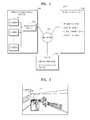
- FIG. 2shows an image captured by the camera 110 illustrated in FIG. 1 , according to an exemplary embodiment.
- a rectangular region in the storeis a monitoring region. If a person exists in the rectangular region, it is determined that there is a customer who looks at a television displayed on a wall.
- the camera 110continuously counts the number of people while capturing the image, and generates counting data as a result of the counting.
- the management device 120controls operation of each of the cameras 110 according to a control signal from the monitoring server 200 or the client 300 . Also, the management device 120 receives and stores images captured by the cameras 110 .
- the management device 120may have a storage capacity according to the number of cameras 110 installed in the store, the number of pixels and/or a frame rate of the images captured by the cameras 110 , a period for storing the captured images, etc.
- the number of cameras 110 to be installed, the number of pixels and/or a frame rate of the images captured by the cameras 110 , a period for storing the captured images, etc.may be determined according to the storage capacity of the management device 120 .
- the management device 120may be a personal computer.
- the management device 120may check a plurality of images captured by the cameras 110 in real time to monitor the store, and thus, may include a display device. In this case, the management device 120 may simultaneously display the captured images. Also, images stored in the management device 120 may be displayed on the display device.
- the cameras 110 and the management device 120are connected via the network 400 to the monitoring server 200 and/or the client 300 .
- FIG. 3is a block diagram of the monitoring server 200 illustrated in FIG. 1 , according to an exemplary embodiment.
- the monitoring server 200backs up images captured by the remote management system 100 of a plurality of stores, and stores counting data generated by the remote management system 100 .
- the monitoring server 200manages a database for storing various types of data regarding the stores.
- the monitoring server 200provides a web page to the client 300 , and allows the client 300 to manage the stores on the web page.
- the monitoring server 200includes a communication unit 210 , a storage unit 220 , and a web server 230 .
- the communication unit 210transmits and receives data or various signals to and from a plurality of cameras 110 installed in the remote management system 100 included in a plurality of stores, the management device 120 , and the client 300 , via the network 400 .
- the communication unit 210receives captured images of the stores and counting data regarding monitoring regions, from the remote management system 100 .
- the storage unit 220may store images captured by and counting data generated by the cameras 110 of the remote management system 100 , and various types of information regarding the cameras 110 installed in the stores.
- the storage unit 220includes an image backup unit 221 , a counting server 222 , and a database 223 .
- the image backup unit 221stores the images captured by the cameras 110 .
- the image backup unit 221may receive and store images currently captured by the cameras 110 in real time. Also, the image backup unit 221 may receive and store images stored in the management device 120 .
- the image backup unit 221may store all images captured by the cameras 110 , or may selectively store images captured only at a certain time.
- the image backup unit 221may permanently store the captured images. However, since a storage capacity of a storage medium is limited, the stored images may be automatically deleted after a certain time or period. Meanwhile, when the captured images are received from the remote management system 100 and are stored in the image backup unit 221 , the monitoring server 200 may control the communication unit 210 to receive the captured image at a preset time, e.g., closing times of the stores.
- the counting server 222stores the counting data received from cameras having a counting function, from among the cameras 110 installed in the stores. If the client 300 requests to transmit the counting data, the counting server 222 transforms the counting data into a graph and transmits the graph to the client 300 . However, the method of transmitting the counting data is not limited thereto. The counting server 222 may transmit the counting data itself to the client 300 , and the client 300 may generate a graph by using the received counting data.
- the database 223stores information regarding the stores managed by the client 300 , and information regarding the cameras 110 installed in the stores.
- the database 223may store information regarding a manager, an address, a phone number, a fax number, selling products, or a map such as a floor plan or a product display map of each of the stores.
- the database 223may store a model name or specifications regarding photographing performances, e.g., a zoom function and a viewing angle, of each of the cameras 110 .
- the web server 230provides a web page for store management so as to allow the client 300 to manage the stores on the web page. Also, the web server 230 transmits to the client 300 the images stored in the image backup unit 221 or the counting data stored in the counting server 222 , according to a control signal received from the client 300 .
- the web server 230provides a program such as Active X or Silverlight to the client 300 who accesses the web server 230 , so as to allow the client 300 to execute various functions provided on the web page.
- the web server 230may directly execute a servlet, and may provide a result of the execution to the client 300 . That is, the web server 230 supports the client 300 to execute various functions on various platforms.
- the web server 230may provide a scheduler to allow the client 300 to easily search the stored images.
- the schedulermay be displayed in the form of a calendar or a table, and may allow reproduction of images stored on a selected date or at a selected time.
- the schedulermay be updated whenever newly captured images are stored in the image backup unit 221 , or the images stored in the image backup unit 221 are deleted.
- the client 300accesses the monitoring server 200 and manages the stores on the web page provided by the web server 230 .
- a plurality of clients 300may exist, and the clients 300 may simultaneously access the monitoring server 200 .
- the client 300executes the program such as Active X or Silverlight provided by the web server 230 , and executes various functions provided by on the web page. Alternatively, the client 300 receives a result of executing various functions, which is transmitted by the web server 230 .
- the client 300may receive and display the images stored in the image backup unit 221 or the management device 120 , or live images currently captured by the cameras 110 . Also, the client 300 may receive and display the counting data stored in the counting server 222 , or the graph generated by using the counting data. Furthermore, the client 300 may add to the database 223 new stores and cameras 110 installed in the new stores, through the web page.
- the network 400refers to a means for transmitting and receiving captured images, various types of data, control signals, etc.
- the network 400may refer to any means for transmitting and receiving data by wire or wirelessly.
- the network 400may connect the cameras 110 , the management device 120 , the monitoring server 200 , and the client 300 by wire, e.g., via cables, or wirelessly, e.g., via a wireless local area network (WLAN).
- WLANwireless local area network
- a method of monitoring a plurality of stores by the monitoring server 200 and the client 300will now be described with reference to FIGS. 4 through 12 .
- FIG. 4is a flowchart of a method of controlling the monitoring server 200 illustrated in FIG. 1 , according to an exemplary embodiment.
- FIGS. 5 through 12are screen images for describing a method of monitoring the stores by the client 300 illustrated in FIG. 1 , according to an exemplary embodiment.
- the web server 230provides a web page for store management to the client 300 (operation S 1 ).
- the client 300inputs an identification (ID) and a password to access the monitoring server 200 .
- a screen of a web page 500 for store managementwhich is provided to the client 300 who inputs the ID and the password and is authorized to access the monitoring server 200 , is illustrated.
- a function selection button 510 for selecting one of ‘Monitoring’ and ‘Setup’ functionsmay be displayed on the screen of the web page 500 .
- a store selection window 520 for selecting a store to be monitored, and a main window 530 for displaying locations of the storesmay be displayed on the screen of the web page 500 .
- the web server 230provides a magnified map of the selected area to the client 300 (operation S 2 ).
- FIG. 6a screen in which the area selected by the client 300 is magnified is illustrated.
- the selected areais a bottom area in the map displayed on the main window 530 of FIG. 5 .
- the stores located in the magnified areaare displayed on the map.
- the client 300selects a certain area on the map displayed on the main window 530 in the above description, the current exemplary embodiment is not limited thereto.
- a certain storemay be selected by sequentially selecting a country selection menu, a city selection menu, and a store selection menu of the store selection window 520 .
- FIG. 7a screen in which the information regarding the store selected by the client 300 is displayed on a store information window 540 is illustrated.
- the screenmay be switched to a screen for managing the selected store.
- a screen in which a guide map 560 of a certain store is displayed on the main window 530 when the store is selected by the client 300 , or the screen is switched from the store information window 540is illustrated.
- the guide map 560may display locations of a plurality of cameras 110 installed in the store.
- the guide map 560may also display, for example, photographing ranges and photographing directions of the installed cameras 110 .
- the client 300may select a certain camera 110 displayed on the guide map 560 . If a certain camera 110 is selected, a menu window 550 for displaying functions executable by the selected camera 110 is displayed (operation S 4 ).
- FIG. 8a screen in which, when a camera 110 for photographing a main gate is selected by the client 300 , the menu window 550 regarding the camera 110 is displayed is illustrated.
- the executable functions‘Live’, ‘Search’, and ‘Number of Visitors’ are displayed.
- the executable functionsare not limited thereto, and various functions executable by the camera 110 may be included in the menu window 550 .
- the web server 230determines which of the displayed functions is selected by the client 300 while the menu window 550 is being displayed (operations S 5 , S 7 , and S 9 ).
- the web server 230connect the selected camera 110 and the client 300 (operation S 6 ). If the camera 110 and the client 300 are connected, a currently captured image is streamed in real time from the camera 110 to the client 300 . In this case, a network address of the camera 110 may be linked to a portion of the menu window 550 for displaying the ‘Live’ function.
- a screen in which, when the client 300 selects the ‘Live’ function, a live menu window 570 for viewing a live image captured by the camera 110 is displayedis illustrated.
- the live menu window 570includes an image window 571 for displaying a currently captured image.
- the live menu window 570may include a camera control window 572 for controlling, for example, a direction and a zoom ratio of the camera 110 .
- the camera control window 572may display various function buttons for controlling the camera 110 .
- function buttons‘Menu’, ‘Auto Zoom’, ‘Preve’, ‘Next’, ‘Default’, ‘Preset’, ‘Pattern’, ‘Scan’, ‘Auto Pan’, ‘IRIS ⁇ , IRIS+’, ‘Near, Far’, and ‘Wide, Tele’ are displayed.
- a PTZ control button for controlling the direction of the camera 110is displayed.
- the function buttonsare not limited thereto. Descriptions of the function buttons will not be provided here and a PTZ control method of the camera 110 will now be described.
- the client 300may control pan, tilt, and zoom operations of the camera 110 .
- the zoom operationmay be controlled by using the ‘Auto Zoom’ button or the ‘Wide, Tele’ button. The control of the pan and tilt operations will be described as follows.
- the camera 110may move from a current position toward the position clicked by the client 300 .
- a moving speed of the camera 110may be controlled according to a distance from the center of the PTZ control button to the clicked position.
- the camera 110may move to a position selected by the client 300 on a panorama image.
- the camera 110is 360°-rotatable.
- the camera 110captures a panorama image 600 by the control of the client 300 or at a preset time.
- the client 300clicks or drags a region 610 on the panorama image 600 .
- the camera 110moves to a position for photographing the clicked or dragged region 610 .
- the client 300may previously set a path for moving the camera 110 such that the camera 110 moves according to the set path.
- the client 300may set the path in such a way that the camera 110 sequentially moves to a plurality of positions.
- the pathis not limited to only one, and one of a plurality of paths may be selected.
- the method of moving the camera 110is not limited thereto, and may be variously changed or added.
- the web server 230streams an image stored in the image backup unit 221 to the client 300 (operation S 8 ).
- the reproduction menu window 580may include function buttons for controlling a current temporal position of the reproduced captured image.
- the web server 230may provide a scheduler 581 to the client 300 so as to allow the client 300 to search for an image captured at a desired time from among the images stored in the image backup unit 221 .
- the client 300may easily reproduce a desired image by searching for a desired date on the scheduler 581 , and reproducing one of images captured on the searched date.
- the web server 230transmits the counting data stored in the counting server 222 to the client 300 (operation S 10 ).
- the statistic window 590may display various graph lines generated by using the counting data. For example, a graph line showing the number of people counted based on time zones, and a graph line showing the number of people counted based on cameras may be displayed. Also, the web server 230 may provide the scheduler 581 so as to allow the client 300 to receive the counting data of a certain date.
- the client 300may add a new store. If the new store is added, store information and information regarding the cameras 110 installed in the new store may also be added. Also, if information regarding the registered stores is changed, the client 300 may update the information stored in the database 223 .
- the clients 300may be grouped into different layers and the clients 300 who belong to different layers may have different authorizations in the monitoring server 200 .
- a client 300 who has an administrator ID for managing the monitoring server 200 itselfmay manage other clients 300 or may add a new client 300 , and may manage all stores and all cameras 110 .
- a client 300 who belongs to a low layermay be authorized to manage only a certain store and a certain camera 110 .
- the client 300may remotely efficiently manage a plurality of stores via the monitoring server 200 and a plurality of cameras 110 included in the remote management system 100 included in each of the stores.
- a program for executing the above monitoring method in the monitoring server 200can be stored in a recording medium, e.g., the storage unit 220 .
- FIG. 13is a block diagram of a monitoring system 2 according to another exemplary embodiment.
- the monitoring system 2includes a remote management system 101 included in each store, a monitoring server 201 , a client 300 , a network 400 , and a mail server 700 .
- a remote management system 101included in each store
- a monitoring server 201when an image or counting data is transmitted from the remote management system 101 of the store to the monitoring server 201 , an email function is added.
- an email functionis added.
- a storeis a target to be managed by the client 300 .
- the storeincludes the remote management system 101 capable of capturing a moving image, a still image, or a panorama image and of generating counting data by counting the number of people who appear in a monitoring region of the moving image.
- the remote management system 101 of the storemay transmit the images and the counting data to the monitoring server 201 by using an email or directly via the network 400 .
- the monitoring server 201receives and stores the images and the counting data from the remote management system 101 of the store, and provides the stored data to the client 300 .
- the client 300accesses the monitoring server 201 and manages a plurality of stores on a web page provided by the web server 230 .
- the network 400refers to a means for transmitting and receiving captured images, various types of data, control signals, etc.
- the network 400may refer to any means for transmitting and receiving data by wire or wirelessly.
- the mail server 700transmits an email received from the remote management system 101 of the store to the monitoring server 201 . If the transmission of the email is successful or fails, the mail server 700 may transmit a transmission success or failure message to the remote management system 101 .
- the mail server 700may be any existing server for providing an email service.
- the remote management system 101 of the storewill now be described in detail.
- FIG. 14is a block diagram of the remote management system 101 illustrated in FIG. 13 , according to an exemplary embodiment.
- the remote management system 101includes one or more cameras 110 through 113 for capturing images, and a management device 130 for controlling the cameras 110 through 113 .
- the cameras 110 through 113capture images of a remote place according to positions where they are installed.
- the cameras 110 through 113may capture at least one of a moving image and a still image, and each of the moving image and the still image may be captured all the time, only at a preset time, or by an indication from the client 300 .
- the cameras 110 through 113may repeatedly capture an image in a fixed cycle.
- At least some of the cameras 110 through 113may include a counter unit having a counting function for counting the number of people.
- the counter unitmay generate counting data by using the counting function.
- a panorama imagemay be captured.
- the panorama imagemay be generated by combining a plurality of still images captured by the PTZ camera while rotating 360° in a horizontal direction.
- the panorama imagemay be captured in a fixed cycle or by an indication from a store manager or the client 300 .
- the cameras 110 through 113transmit to the management device 130 the moving image, the still image, the panorama image, and/or the counting data according to the camera functions.
- the management device 130controls operation of the cameras 110 through 113 , and transmits the images or the data to the monitoring server 201 .
- the management device 130may include a control unit 131 , a local storage unit 132 , a mail transmission unit 137 , and a local communication unit 138 .
- the control unit 131controls operation of the cameras 110 through 113 and elements of the management device 130 .
- the control unit 131determines whether the monitoring server 201 is blocked to access the remote management system 101 by a fire wall, and transmits data to be transmitted to the monitoring server 201 by using an email or directly according to a result of the determination.
- the control unit 131may previously determine whether the monitoring server 201 is blocked to access the remote management system 101 by a fire wall and may previously set a method of transmitting data.
- the local storage unit 132stores various types of data.
- the local storage unit 132includes a moving image storage unit 133 for storing moving images, a still image storage unit 134 for storing still images, a panorama image storage unit 135 for storing panorama images, and a counting data storage unit 136 for storing counting data.
- the sub-storage units 133 through 136 included in the local storage unit 132may not necessarily be separate in hardware, and may be one storage medium.
- the moving image storage unit 133 , the still image storage unit 134 , the panorama image storage unit 135 , and the counting data storage unit 136may refer to divided regions on the storage medium, or may be elements corresponding folders in a computer.
- the mail transmission unit 137attaches an image stored in the local storage unit 132 to an email, and transmits the email to the monitoring server 201 .
- the mail transmission unit 137may be used to transmit a captured image or counting data to the monitoring server 201 when the monitoring server 201 is blocked to access the remote management system 101 by a fire wall.
- the mail transmission unit 137may transmit data to be transmitted by using an email if the data has a small size.
- the mail transmission unit 137may transmit a still image, a panorama image, and/or counting data, which has a relatively small size.
- the data transmitted by the mail transmission unit 137is not limited thereto. If a moving image is in a range of size attachable to an email, the moving image may be attached to an email and may be transmitted to the monitoring server 201 .
- the mail transmission unit 137transmits an email, to which an image and/or data is attached, via the network 400 , the mail server 700 receives the transmitted email, and the monitoring server 201 extracts and stores a file attached to the email received by the mail server 700 .
- the mail transmission unit 137may automatically transmit the email at a fixed time.
- the mail transmission unit 137may attach to the email an image and/or data stored in a corresponding sub-storage unit at the time when the email is written.
- the fixed timemay be a time when the amount of traffic on the network 400 is small.
- the fixed timemay be a time immediately before the store is closed. That is, the fixed time may be a time fixed according to an intention of the client 300 .
- the local communication unit 138transmits an image stored in the local storage unit 132 directly to the monitoring server 201 via the network 400 .
- the local communication unit 138may transmit a currently captured live image to the monitoring server 201 .
- the local communication unit 138may be used to transmit a captured image and/or counting data to the monitoring server 201 when the monitoring server 201 is allowed to access the remote management system 101 .
- the local communication unit 138may be used when information to be transmitted has a relatively large size.
- the control unit 131may delete transmitted image and/or data. That is, if an email to which a still image, a panorama image, and/or counting data are attached is successfully transmitted to the monitoring server 201 , the control unit 131 may delete a file of the still image transmitted from the still image storage unit 134 , may delete a file of the panorama image transmitted from the panorama image storage unit 135 , and/or may delete the counting data stored in the counting data storage unit 136 .
- the mail transmission unit 137 using the email and the local communication unit 138 directly transmitting the stored image to the monitoring server 201are configured to be separated devices as the device for transmitting the stored image to the monitoring server 201 , the present exemplary embodiment is not limited thereto.
- the mail transmission unit 137 and the local communication unit 138may be integrated in a device having a communication function, and the device may perform both data transmitting methods.
- FIG. 15is an image of a screen for setting a method of transmitting an email in the remote management system 101 illustrated in FIG. 14 , according to an exemplary embodiment.
- the client 300 or a store managermay set a ‘Server’ address, a ‘Port’ number, a ‘Login ID’, a ‘Passwd’, a ‘Sender’ address, a ‘Receiver’ address, etc.
- a path of a folder in which data to be attached to the emailmay be set.
- a ‘Still Image Path’is a menu for setting a path of a folder from which still image data is attached
- a ‘People Counting Path’is a menu for setting a path of a folder from which counting data is attached
- a ‘Panorama Image Path’is a menu for setting a path of a folder from which panorama image data is attached.
- a ‘Capture Time’is a menu for setting a time for capturing a still image and a panorama image by the cameras 110 through 113 . If the ‘Capture Time’ is set, files including data of a still image and a panorama image are generated at the set time and are stored in corresponding folders.
- the counter unitcontinuously generates new data while a moving image is being captured. Accordingly, the counter unit may periodically update the counting data by storing generated counting data in a corresponding folder, and adding newly generated counting data. Alternatively, the counter unit may store counting data to be transmitted in a corresponding folder before a time for transmitting an email.
- a ‘Mail Send Time’is a menu for setting a time for transmitting an email.
- an emailmay be automatically transmitted at the set time.
- the email to be transmittedmay be transmitted by attaching the still image, the panorama image, and/or the counting data from the previously set paths of folders.
- the client 300 or the store managermay select a ‘Panorama Capture’ button or an ‘Image Capture’ button to capture a panorama image or a still image at a desired time, or may select a ‘Now Capture & Send’ button to transmit an image immediately after the image is captured. Also, a ‘Mail Send’ button may be selected to immediately send an email by attaching files currently stored in folders.
- FIG. 16is a block diagram of the monitoring server 201 illustrated in FIG. 13 , according to an exemplary embodiment.
- a function of receiving data from the remote management system 101 by using an emailis added.
- differences from the monitoring server 200 illustrated in FIG. 3will be mainly described and repeated descriptions will not be provided.
- the monitoring server 201may further include a mail reception unit 240 in addition to the communication unit 210 , the storage unit 220 , and the web server 230 .
- the mail reception unit 240downloads the still image, the panorama image, and/or the counting data attached to the email from the mail server 700 , and stores them in the image backup unit 221 and the counting server 222 . If a moving image is transmitted by using an email, the mail reception unit 240 may store the moving image in the image backup unit 221 .
- FIGS. 17 and 18are flowcharts of a remote management method according to an exemplary embodiment.
- a moving imageis captured (operation S 20 ). If it is set to capture a moving image for 24 hours, the moving image may be captured without an additional indication.
- the captured moving imageis stored in a first folder for storing moving images (operation S 21 ).
- counting datais generated by counting the number of people who appear in a monitoring region set on the captured moving image (operation S 22 ).
- the generated counting datais stored in a second folder (operation S 23 ).
- the second foldermay be the ‘PeopleCounting’ folder illustrated in FIG. 15 .
- a still imageis captured (operation S 25 ), and the captured still image is stored in a third folder (operation S 26 ).
- a panorama imageis captured (operation S 27 ), and the captured panorama image is stored in a fourth folder (operation S 28 ).
- the third and fourth foldersmay be the ‘StillImage’ folder and the ‘PanoramaImage’ folder, respectively, as illustrated in FIG. 15 .
- an emailis transmitted to the monitoring server 201 by attaching the stored still image, the panorama image, and/or the counting data (operation S 30 ).
- operation S 29it is determined whether an external access to the remote management system 101 is blocked by a fire wall (operation S 31 ). The determination may be performed when the remote management system 101 is installed or whenever an email is transmitted.
- image and/or datais directly transmitted to the monitoring server 201 by using the local communication unit 138 (operation S 36 ).
- a still image, a panorama image, and/or counting dataare extracted from set paths and are attached to an email (operation S 32 ).
- the emailis transmitted to the mail server 700 to be downloaded to the monitoring server 201 (operation S 33 ).
- operation S 34After the email is transmitted, it is determined whether the email is successfully transmitted (operation S 34 ). If the transmission of the email fails, the method returns to operation S 32 and the email is transmitted again. On the other hand, if the email is successfully transmitted, files of the transmitted image and/or data are deleted from corresponding folders (operation S 35 ).
- the client 300may remotely efficiently manage a plurality of stores by efficiently transmitting image and/or data from the remote management system 101 to the monitoring server 201 .
- a program for executing the above remote management method in the remote management system 101can be stored in a recording medium, e.g., the local storage unit 132 .
Landscapes
- Engineering & Computer Science (AREA)
- Computer Networks & Wireless Communication (AREA)
- Signal Processing (AREA)
- Closed-Circuit Television Systems (AREA)
- Alarm Systems (AREA)
Abstract
Description
Claims (14)
Applications Claiming Priority (4)
| Application Number | Priority Date | Filing Date | Title |
|---|---|---|---|
| KR10-2010-0100754 | 2010-10-15 | ||
| KR20100100754 | 2010-10-15 | ||
| KR10-2011-0103890 | 2011-10-12 | ||
| KR1020110103890AKR101842020B1 (en) | 2010-10-15 | 2011-10-12 | Remote management system, remote management method, and monitoring server |
Publications (2)
| Publication Number | Publication Date |
|---|---|
| US20120092447A1 US20120092447A1 (en) | 2012-04-19 |
| US9160784B2true US9160784B2 (en) | 2015-10-13 |
Family
ID=45933816
Family Applications (1)
| Application Number | Title | Priority Date | Filing Date |
|---|---|---|---|
| US13/274,784Active2032-09-19US9160784B2 (en) | 2010-10-15 | 2011-10-17 | Remote management system, remote management method, and monitoring server |
Country Status (1)
| Country | Link |
|---|---|
| US (1) | US9160784B2 (en) |
Cited By (87)
| Publication number | Priority date | Publication date | Assignee | Title |
|---|---|---|---|---|
| US20160171853A1 (en)* | 1999-07-20 | 2016-06-16 | Comcast Cable Communications, Llc | Video security systems and methods |
| US20160274759A1 (en) | 2008-08-25 | 2016-09-22 | Paul J. Dawes | Security system with networked touchscreen and gateway |
| US10051078B2 (en) | 2007-06-12 | 2018-08-14 | Icontrol Networks, Inc. | WiFi-to-serial encapsulation in systems |
| US10062245B2 (en) | 2005-03-16 | 2018-08-28 | Icontrol Networks, Inc. | Cross-client sensor user interface in an integrated security network |
| US10062273B2 (en) | 2010-09-28 | 2018-08-28 | Icontrol Networks, Inc. | Integrated security system with parallel processing architecture |
| US10078958B2 (en) | 2010-12-17 | 2018-09-18 | Icontrol Networks, Inc. | Method and system for logging security event data |
| US10079839B1 (en) | 2007-06-12 | 2018-09-18 | Icontrol Networks, Inc. | Activation of gateway device |
| US10091014B2 (en) | 2005-03-16 | 2018-10-02 | Icontrol Networks, Inc. | Integrated security network with security alarm signaling system |
| US10127801B2 (en) | 2005-03-16 | 2018-11-13 | Icontrol Networks, Inc. | Integrated security system with parallel processing architecture |
| US10142392B2 (en) | 2007-01-24 | 2018-11-27 | Icontrol Networks, Inc. | Methods and systems for improved system performance |
| US10142166B2 (en) | 2004-03-16 | 2018-11-27 | Icontrol Networks, Inc. | Takeover of security network |
| US10142394B2 (en) | 2007-06-12 | 2018-11-27 | Icontrol Networks, Inc. | Generating risk profile using data of home monitoring and security system |
| US10140840B2 (en) | 2007-04-23 | 2018-11-27 | Icontrol Networks, Inc. | Method and system for providing alternate network access |
| US10156959B2 (en) | 2005-03-16 | 2018-12-18 | Icontrol Networks, Inc. | Cross-client sensor user interface in an integrated security network |
| US10156831B2 (en) | 2004-03-16 | 2018-12-18 | Icontrol Networks, Inc. | Automation system with mobile interface |
| US10200504B2 (en) | 2007-06-12 | 2019-02-05 | Icontrol Networks, Inc. | Communication protocols over internet protocol (IP) networks |
| US10237806B2 (en) | 2009-04-30 | 2019-03-19 | Icontrol Networks, Inc. | Activation of a home automation controller |
| US10237237B2 (en) | 2007-06-12 | 2019-03-19 | Icontrol Networks, Inc. | Communication protocols in integrated systems |
| US10313303B2 (en) | 2007-06-12 | 2019-06-04 | Icontrol Networks, Inc. | Forming a security network including integrated security system components and network devices |
| US10339791B2 (en) | 2007-06-12 | 2019-07-02 | Icontrol Networks, Inc. | Security network integrated with premise security system |
| US10348575B2 (en) | 2013-06-27 | 2019-07-09 | Icontrol Networks, Inc. | Control system user interface |
| US10365810B2 (en) | 2007-06-12 | 2019-07-30 | Icontrol Networks, Inc. | Control system user interface |
| US10382452B1 (en) | 2007-06-12 | 2019-08-13 | Icontrol Networks, Inc. | Communication protocols in integrated systems |
| US10380871B2 (en) | 2005-03-16 | 2019-08-13 | Icontrol Networks, Inc. | Control system user interface |
| US10389736B2 (en) | 2007-06-12 | 2019-08-20 | Icontrol Networks, Inc. | Communication protocols in integrated systems |
| US10423309B2 (en) | 2007-06-12 | 2019-09-24 | Icontrol Networks, Inc. | Device integration framework |
| US10498830B2 (en) | 2007-06-12 | 2019-12-03 | Icontrol Networks, Inc. | Wi-Fi-to-serial encapsulation in systems |
| US10522026B2 (en) | 2008-08-11 | 2019-12-31 | Icontrol Networks, Inc. | Automation system user interface with three-dimensional display |
| US10523689B2 (en) | 2007-06-12 | 2019-12-31 | Icontrol Networks, Inc. | Communication protocols over internet protocol (IP) networks |
| US10530839B2 (en) | 2008-08-11 | 2020-01-07 | Icontrol Networks, Inc. | Integrated cloud system with lightweight gateway for premises automation |
| US10559193B2 (en) | 2002-02-01 | 2020-02-11 | Comcast Cable Communications, Llc | Premises management systems |
| US10616075B2 (en) | 2007-06-12 | 2020-04-07 | Icontrol Networks, Inc. | Communication protocols in integrated systems |
| US10666523B2 (en) | 2007-06-12 | 2020-05-26 | Icontrol Networks, Inc. | Communication protocols in integrated systems |
| US10721087B2 (en) | 2005-03-16 | 2020-07-21 | Icontrol Networks, Inc. | Method for networked touchscreen with integrated interfaces |
| US10747216B2 (en) | 2007-02-28 | 2020-08-18 | Icontrol Networks, Inc. | Method and system for communicating with and controlling an alarm system from a remote server |
| US10785319B2 (en) | 2006-06-12 | 2020-09-22 | Icontrol Networks, Inc. | IP device discovery systems and methods |
| US10841381B2 (en) | 2005-03-16 | 2020-11-17 | Icontrol Networks, Inc. | Security system with networked touchscreen |
| US10979389B2 (en) | 2004-03-16 | 2021-04-13 | Icontrol Networks, Inc. | Premises management configuration and control |
| US10999254B2 (en) | 2005-03-16 | 2021-05-04 | Icontrol Networks, Inc. | System for data routing in networks |
| US11089122B2 (en) | 2007-06-12 | 2021-08-10 | Icontrol Networks, Inc. | Controlling data routing among networks |
| US11113950B2 (en) | 2005-03-16 | 2021-09-07 | Icontrol Networks, Inc. | Gateway integrated with premises security system |
| US11146637B2 (en) | 2014-03-03 | 2021-10-12 | Icontrol Networks, Inc. | Media content management |
| US11153266B2 (en) | 2004-03-16 | 2021-10-19 | Icontrol Networks, Inc. | Gateway registry methods and systems |
| US11182060B2 (en) | 2004-03-16 | 2021-11-23 | Icontrol Networks, Inc. | Networked touchscreen with integrated interfaces |
| US11201755B2 (en) | 2004-03-16 | 2021-12-14 | Icontrol Networks, Inc. | Premises system management using status signal |
| US11212192B2 (en) | 2007-06-12 | 2021-12-28 | Icontrol Networks, Inc. | Communication protocols in integrated systems |
| US11218878B2 (en) | 2007-06-12 | 2022-01-04 | Icontrol Networks, Inc. | Communication protocols in integrated systems |
| US11240059B2 (en) | 2010-12-20 | 2022-02-01 | Icontrol Networks, Inc. | Defining and implementing sensor triggered response rules |
| US11237714B2 (en) | 2007-06-12 | 2022-02-01 | Control Networks, Inc. | Control system user interface |
| US11244545B2 (en) | 2004-03-16 | 2022-02-08 | Icontrol Networks, Inc. | Cross-client sensor user interface in an integrated security network |
| US11258625B2 (en) | 2008-08-11 | 2022-02-22 | Icontrol Networks, Inc. | Mobile premises automation platform |
| US11277465B2 (en) | 2004-03-16 | 2022-03-15 | Icontrol Networks, Inc. | Generating risk profile using data of home monitoring and security system |
| US11310199B2 (en) | 2004-03-16 | 2022-04-19 | Icontrol Networks, Inc. | Premises management configuration and control |
| US11316753B2 (en) | 2007-06-12 | 2022-04-26 | Icontrol Networks, Inc. | Communication protocols in integrated systems |
| US11316958B2 (en) | 2008-08-11 | 2022-04-26 | Icontrol Networks, Inc. | Virtual device systems and methods |
| US11343380B2 (en) | 2004-03-16 | 2022-05-24 | Icontrol Networks, Inc. | Premises system automation |
| US11368327B2 (en) | 2008-08-11 | 2022-06-21 | Icontrol Networks, Inc. | Integrated cloud system for premises automation |
| US11398147B2 (en) | 2010-09-28 | 2022-07-26 | Icontrol Networks, Inc. | Method, system and apparatus for automated reporting of account and sensor zone information to a central station |
| US11405463B2 (en) | 2014-03-03 | 2022-08-02 | Icontrol Networks, Inc. | Media content management |
| US11424980B2 (en) | 2005-03-16 | 2022-08-23 | Icontrol Networks, Inc. | Forming a security network including integrated security system components |
| US11423756B2 (en) | 2007-06-12 | 2022-08-23 | Icontrol Networks, Inc. | Communication protocols in integrated systems |
| US11451409B2 (en) | 2005-03-16 | 2022-09-20 | Icontrol Networks, Inc. | Security network integrating security system and network devices |
| US11489812B2 (en) | 2004-03-16 | 2022-11-01 | Icontrol Networks, Inc. | Forming a security network including integrated security system components and network devices |
| US11496568B2 (en) | 2005-03-16 | 2022-11-08 | Icontrol Networks, Inc. | Security system with networked touchscreen |
| US11582065B2 (en) | 2007-06-12 | 2023-02-14 | Icontrol Networks, Inc. | Systems and methods for device communication |
| US11601810B2 (en) | 2007-06-12 | 2023-03-07 | Icontrol Networks, Inc. | Communication protocols in integrated systems |
| US11615697B2 (en) | 2005-03-16 | 2023-03-28 | Icontrol Networks, Inc. | Premise management systems and methods |
| US11646907B2 (en) | 2007-06-12 | 2023-05-09 | Icontrol Networks, Inc. | Communication protocols in integrated systems |
| US11677577B2 (en) | 2004-03-16 | 2023-06-13 | Icontrol Networks, Inc. | Premises system management using status signal |
| US11700142B2 (en) | 2005-03-16 | 2023-07-11 | Icontrol Networks, Inc. | Security network integrating security system and network devices |
| US11706045B2 (en) | 2005-03-16 | 2023-07-18 | Icontrol Networks, Inc. | Modular electronic display platform |
| US11706279B2 (en) | 2007-01-24 | 2023-07-18 | Icontrol Networks, Inc. | Methods and systems for data communication |
| US11729255B2 (en) | 2008-08-11 | 2023-08-15 | Icontrol Networks, Inc. | Integrated cloud system with lightweight gateway for premises automation |
| US11750414B2 (en) | 2010-12-16 | 2023-09-05 | Icontrol Networks, Inc. | Bidirectional security sensor communication for a premises security system |
| US11758026B2 (en) | 2008-08-11 | 2023-09-12 | Icontrol Networks, Inc. | Virtual device systems and methods |
| US11792036B2 (en) | 2008-08-11 | 2023-10-17 | Icontrol Networks, Inc. | Mobile premises automation platform |
| US11792330B2 (en) | 2005-03-16 | 2023-10-17 | Icontrol Networks, Inc. | Communication and automation in a premises management system |
| US11811845B2 (en) | 2004-03-16 | 2023-11-07 | Icontrol Networks, Inc. | Communication protocols over internet protocol (IP) networks |
| US11816323B2 (en) | 2008-06-25 | 2023-11-14 | Icontrol Networks, Inc. | Automation system user interface |
| US11831462B2 (en) | 2007-08-24 | 2023-11-28 | Icontrol Networks, Inc. | Controlling data routing in premises management systems |
| US11916928B2 (en) | 2008-01-24 | 2024-02-27 | Icontrol Networks, Inc. | Communication protocols over internet protocol (IP) networks |
| US11916870B2 (en) | 2004-03-16 | 2024-02-27 | Icontrol Networks, Inc. | Gateway registry methods and systems |
| US12003387B2 (en) | 2012-06-27 | 2024-06-04 | Comcast Cable Communications, Llc | Control system user interface |
| US12063221B2 (en) | 2006-06-12 | 2024-08-13 | Icontrol Networks, Inc. | Activation of gateway device |
| US12063220B2 (en) | 2004-03-16 | 2024-08-13 | Icontrol Networks, Inc. | Communication protocols in integrated systems |
| US12184443B2 (en) | 2007-06-12 | 2024-12-31 | Icontrol Networks, Inc. | Controlling data routing among networks |
| US12283172B2 (en) | 2007-06-12 | 2025-04-22 | Icontrol Networks, Inc. | Communication protocols in integrated systems |
Families Citing this family (11)
| Publication number | Priority date | Publication date | Assignee | Title |
|---|---|---|---|---|
| US20180198788A1 (en)* | 2007-06-12 | 2018-07-12 | Icontrol Networks, Inc. | Security system integrated with social media platform |
| US20140267595A1 (en)* | 2013-03-15 | 2014-09-18 | Mark J. Cuddeback | Rotating surveillance camera |
| USD781318S1 (en)* | 2014-04-22 | 2017-03-14 | Google Inc. | Display screen with graphical user interface or portion thereof |
| USD781317S1 (en) | 2014-04-22 | 2017-03-14 | Google Inc. | Display screen with graphical user interface or portion thereof |
| US9934222B2 (en) | 2014-04-22 | 2018-04-03 | Google Llc | Providing a thumbnail image that follows a main image |
| USD780777S1 (en) | 2014-04-22 | 2017-03-07 | Google Inc. | Display screen with graphical user interface or portion thereof |
| US9972121B2 (en) | 2014-04-22 | 2018-05-15 | Google Llc | Selecting time-distributed panoramic images for display |
| CA2894359C (en)* | 2014-06-16 | 2022-07-05 | Braeburn Systems Llc | Graphical highlight for programming a control |
| KR102474729B1 (en)* | 2016-06-28 | 2022-12-05 | 한화테크윈 주식회사 | The Apparatus For Mornitoring |
| JP6855964B2 (en)* | 2017-07-11 | 2021-04-07 | 株式会社リコー | Information input device, information processing system, program, information processing method |
| JP7584694B1 (en)* | 2024-03-13 | 2024-11-15 | 電気興業株式会社 | Attribute analysis system, and estimation method and communication method using the same |
Citations (28)
| Publication number | Priority date | Publication date | Assignee | Title |
|---|---|---|---|---|
| JP2000134522A (en) | 1997-12-04 | 2000-05-12 | Digital Camera Network | Integrated type internet camera and internet camera system |
| US6321336B1 (en)* | 1998-03-13 | 2001-11-20 | Secure Computing Corporation | System and method for redirecting network traffic to provide secure communication |
| US6335742B1 (en)* | 1997-07-24 | 2002-01-01 | Ricoh Company, Ltd. | Apparatus for file management and manipulation using graphical displays and textual descriptions |
| KR20020008416A (en) | 2002-01-03 | 2002-01-30 | 신동수 | A methode or service for saving and a picture to remote server by email on the internet and checking it |
| US20030071902A1 (en)* | 2001-10-11 | 2003-04-17 | Allen Paul G. | System, devices, and methods for switching between video cameras |
| JP2003233558A (en) | 2002-02-07 | 2003-08-22 | Canon Inc | Communication device and control method thereof |
| US20030200266A1 (en)* | 2002-04-19 | 2003-10-23 | Henry Steven G. | Device transmission tracking |
| KR20030084441A (en) | 2002-04-26 | 2003-11-01 | 유한종 | Video and digital recording system |
| JP2004234103A (en) | 2003-01-28 | 2004-08-19 | Computer Image Laboratory Co Ltd | Information acquisition system in POS terminal |
| US20040165546A1 (en)* | 2003-01-13 | 2004-08-26 | Roskind James A. | Time based wireless access provisioning |
| US6985620B2 (en) | 2000-03-07 | 2006-01-10 | Sarnoff Corporation | Method of pose estimation and model refinement for video representation of a three dimensional scene |
| US20060070108A1 (en)* | 2004-09-30 | 2006-03-30 | Martin Renkis | Wireless video surveillance system & method with digital input recorder interface and setup |
| KR20060030078A (en) | 2006-02-20 | 2006-04-07 | 박창영 | Network security system supporting multiple video storage and retrieval for efficient network video retrieval from clients |
| JP2006175215A (en) | 2004-11-24 | 2006-07-06 | Olympus Corp | Endoscope control system |
| US20070299918A1 (en)* | 2006-06-27 | 2007-12-27 | Research In Motion Limited | Electronic Mail Communications System with Client Email Internet Service Provider (ISP) Polling Application and Related Methods |
| US7460149B1 (en)* | 2007-05-28 | 2008-12-02 | Kd Secure, Llc | Video data storage, search, and retrieval using meta-data and attribute data in a video surveillance system |
| US20080309759A1 (en)* | 2007-06-15 | 2008-12-18 | At&T Knowledge Ventures, L.P. | STB/DVR video surveillance |
| KR20090078982A (en) | 2008-01-16 | 2009-07-21 | 삼성전자주식회사 | Area based object counting device and method |
| US20100011435A1 (en)* | 2008-07-08 | 2010-01-14 | Asp Works Pte Ltd | Method and System for Providing Guaranteed File Transfer in Corporate Environment Behind Firewall |
| KR20100005960A (en) | 2008-07-08 | 2010-01-18 | (주)인덱스미디어 | Information system for fashion |
| KR20100013469A (en) | 2008-07-31 | 2010-02-10 | 케이티하이텔 주식회사 | Real-time image offer system and real-time image offer method |
| US20100141762A1 (en)* | 2006-11-20 | 2010-06-10 | Jon Siann | Wireless Network Camera Systems |
| US7739334B1 (en)* | 2000-03-17 | 2010-06-15 | Visto Corporation | System and method for automatically forwarding email and email events via a computer network to a server computer |
| US7792256B1 (en)* | 2005-03-25 | 2010-09-07 | Arledge Charles E | System and method for remotely monitoring, controlling, and managing devices at one or more premises |
| US20100328461A1 (en)* | 2004-09-23 | 2010-12-30 | Renkis Martin A | Wireless Video Surveillance System and Method with Two-Way Locking of Input Capture Devices |
| US7886048B1 (en)* | 2007-07-31 | 2011-02-08 | Sutus, Inc. | Systems and methods for managing integrated systems with use cases |
| JP2011175584A (en) | 2010-02-25 | 2011-09-08 | Gear Nouve Co Ltd | Construction site management system, server and digital camera |
| US8520068B2 (en)* | 1999-07-20 | 2013-08-27 | Comcast Cable Communications, Llc | Video security system |
- 2011
- 2011-10-17USUS13/274,784patent/US9160784B2/enactiveActive
Patent Citations (28)
| Publication number | Priority date | Publication date | Assignee | Title |
|---|---|---|---|---|
| US6335742B1 (en)* | 1997-07-24 | 2002-01-01 | Ricoh Company, Ltd. | Apparatus for file management and manipulation using graphical displays and textual descriptions |
| JP2000134522A (en) | 1997-12-04 | 2000-05-12 | Digital Camera Network | Integrated type internet camera and internet camera system |
| US6321336B1 (en)* | 1998-03-13 | 2001-11-20 | Secure Computing Corporation | System and method for redirecting network traffic to provide secure communication |
| US8520068B2 (en)* | 1999-07-20 | 2013-08-27 | Comcast Cable Communications, Llc | Video security system |
| US6985620B2 (en) | 2000-03-07 | 2006-01-10 | Sarnoff Corporation | Method of pose estimation and model refinement for video representation of a three dimensional scene |
| US7739334B1 (en)* | 2000-03-17 | 2010-06-15 | Visto Corporation | System and method for automatically forwarding email and email events via a computer network to a server computer |
| US20030071902A1 (en)* | 2001-10-11 | 2003-04-17 | Allen Paul G. | System, devices, and methods for switching between video cameras |
| KR20020008416A (en) | 2002-01-03 | 2002-01-30 | 신동수 | A methode or service for saving and a picture to remote server by email on the internet and checking it |
| JP2003233558A (en) | 2002-02-07 | 2003-08-22 | Canon Inc | Communication device and control method thereof |
| US20030200266A1 (en)* | 2002-04-19 | 2003-10-23 | Henry Steven G. | Device transmission tracking |
| KR20030084441A (en) | 2002-04-26 | 2003-11-01 | 유한종 | Video and digital recording system |
| US20040165546A1 (en)* | 2003-01-13 | 2004-08-26 | Roskind James A. | Time based wireless access provisioning |
| JP2004234103A (en) | 2003-01-28 | 2004-08-19 | Computer Image Laboratory Co Ltd | Information acquisition system in POS terminal |
| US20100328461A1 (en)* | 2004-09-23 | 2010-12-30 | Renkis Martin A | Wireless Video Surveillance System and Method with Two-Way Locking of Input Capture Devices |
| US20060070108A1 (en)* | 2004-09-30 | 2006-03-30 | Martin Renkis | Wireless video surveillance system & method with digital input recorder interface and setup |
| JP2006175215A (en) | 2004-11-24 | 2006-07-06 | Olympus Corp | Endoscope control system |
| US7792256B1 (en)* | 2005-03-25 | 2010-09-07 | Arledge Charles E | System and method for remotely monitoring, controlling, and managing devices at one or more premises |
| KR20060030078A (en) | 2006-02-20 | 2006-04-07 | 박창영 | Network security system supporting multiple video storage and retrieval for efficient network video retrieval from clients |
| US20070299918A1 (en)* | 2006-06-27 | 2007-12-27 | Research In Motion Limited | Electronic Mail Communications System with Client Email Internet Service Provider (ISP) Polling Application and Related Methods |
| US20100141762A1 (en)* | 2006-11-20 | 2010-06-10 | Jon Siann | Wireless Network Camera Systems |
| US7460149B1 (en)* | 2007-05-28 | 2008-12-02 | Kd Secure, Llc | Video data storage, search, and retrieval using meta-data and attribute data in a video surveillance system |
| US20080309759A1 (en)* | 2007-06-15 | 2008-12-18 | At&T Knowledge Ventures, L.P. | STB/DVR video surveillance |
| US7886048B1 (en)* | 2007-07-31 | 2011-02-08 | Sutus, Inc. | Systems and methods for managing integrated systems with use cases |
| KR20090078982A (en) | 2008-01-16 | 2009-07-21 | 삼성전자주식회사 | Area based object counting device and method |
| KR20100005960A (en) | 2008-07-08 | 2010-01-18 | (주)인덱스미디어 | Information system for fashion |
| US20100011435A1 (en)* | 2008-07-08 | 2010-01-14 | Asp Works Pte Ltd | Method and System for Providing Guaranteed File Transfer in Corporate Environment Behind Firewall |
| KR20100013469A (en) | 2008-07-31 | 2010-02-10 | 케이티하이텔 주식회사 | Real-time image offer system and real-time image offer method |
| JP2011175584A (en) | 2010-02-25 | 2011-09-08 | Gear Nouve Co Ltd | Construction site management system, server and digital camera |
Non-Patent Citations (1)
| Title |
|---|
| Communication dated Sep. 20, 2011, from the Korean Intellectual Property Office issued in counterpart Korean Application No. 10-2010-0100754. |
Cited By (178)
| Publication number | Priority date | Publication date | Assignee | Title |
|---|---|---|---|---|
| US20160171853A1 (en)* | 1999-07-20 | 2016-06-16 | Comcast Cable Communications, Llc | Video security systems and methods |
| US10559193B2 (en) | 2002-02-01 | 2020-02-11 | Comcast Cable Communications, Llc | Premises management systems |
| US11310199B2 (en) | 2004-03-16 | 2022-04-19 | Icontrol Networks, Inc. | Premises management configuration and control |
| US11277465B2 (en) | 2004-03-16 | 2022-03-15 | Icontrol Networks, Inc. | Generating risk profile using data of home monitoring and security system |
| US11368429B2 (en) | 2004-03-16 | 2022-06-21 | Icontrol Networks, Inc. | Premises management configuration and control |
| US12063220B2 (en) | 2004-03-16 | 2024-08-13 | Icontrol Networks, Inc. | Communication protocols in integrated systems |
| US11244545B2 (en) | 2004-03-16 | 2022-02-08 | Icontrol Networks, Inc. | Cross-client sensor user interface in an integrated security network |
| US11378922B2 (en) | 2004-03-16 | 2022-07-05 | Icontrol Networks, Inc. | Automation system with mobile interface |
| US11410531B2 (en) | 2004-03-16 | 2022-08-09 | Icontrol Networks, Inc. | Automation system user interface with three-dimensional display |
| US11991306B2 (en) | 2004-03-16 | 2024-05-21 | Icontrol Networks, Inc. | Premises system automation |
| US11201755B2 (en) | 2004-03-16 | 2021-12-14 | Icontrol Networks, Inc. | Premises system management using status signal |
| US10142166B2 (en) | 2004-03-16 | 2018-11-27 | Icontrol Networks, Inc. | Takeover of security network |
| US11916870B2 (en) | 2004-03-16 | 2024-02-27 | Icontrol Networks, Inc. | Gateway registry methods and systems |
| US11182060B2 (en) | 2004-03-16 | 2021-11-23 | Icontrol Networks, Inc. | Networked touchscreen with integrated interfaces |
| US11184322B2 (en) | 2004-03-16 | 2021-11-23 | Icontrol Networks, Inc. | Communication protocols in integrated systems |
| US10156831B2 (en) | 2004-03-16 | 2018-12-18 | Icontrol Networks, Inc. | Automation system with mobile interface |
| US11893874B2 (en) | 2004-03-16 | 2024-02-06 | Icontrol Networks, Inc. | Networked touchscreen with integrated interfaces |
| US11175793B2 (en) | 2004-03-16 | 2021-11-16 | Icontrol Networks, Inc. | User interface in a premises network |
| US11159484B2 (en) | 2004-03-16 | 2021-10-26 | Icontrol Networks, Inc. | Forming a security network including integrated security system components and network devices |
| US11810445B2 (en) | 2004-03-16 | 2023-11-07 | Icontrol Networks, Inc. | Cross-client sensor user interface in an integrated security network |
| US11153266B2 (en) | 2004-03-16 | 2021-10-19 | Icontrol Networks, Inc. | Gateway registry methods and systems |
| US11811845B2 (en) | 2004-03-16 | 2023-11-07 | Icontrol Networks, Inc. | Communication protocols over internet protocol (IP) networks |
| US11757834B2 (en) | 2004-03-16 | 2023-09-12 | Icontrol Networks, Inc. | Communication protocols in integrated systems |
| US10692356B2 (en) | 2004-03-16 | 2020-06-23 | Icontrol Networks, Inc. | Control system user interface |
| US11782394B2 (en) | 2004-03-16 | 2023-10-10 | Icontrol Networks, Inc. | Automation system with mobile interface |
| US12253833B2 (en) | 2004-03-16 | 2025-03-18 | Icontrol Networks, Inc. | Automation system with mobile interface |
| US11449012B2 (en) | 2004-03-16 | 2022-09-20 | Icontrol Networks, Inc. | Premises management networking |
| US11082395B2 (en) | 2004-03-16 | 2021-08-03 | Icontrol Networks, Inc. | Premises management configuration and control |
| US11043112B2 (en) | 2004-03-16 | 2021-06-22 | Icontrol Networks, Inc. | Integrated security system with parallel processing architecture |
| US10992784B2 (en) | 2004-03-16 | 2021-04-27 | Control Networks, Inc. | Communication protocols over internet protocol (IP) networks |
| US11677577B2 (en) | 2004-03-16 | 2023-06-13 | Icontrol Networks, Inc. | Premises system management using status signal |
| US10979389B2 (en) | 2004-03-16 | 2021-04-13 | Icontrol Networks, Inc. | Premises management configuration and control |
| US11656667B2 (en) | 2004-03-16 | 2023-05-23 | Icontrol Networks, Inc. | Integrated security system with parallel processing architecture |
| US10447491B2 (en) | 2004-03-16 | 2019-10-15 | Icontrol Networks, Inc. | Premises system management using status signal |
| US11625008B2 (en) | 2004-03-16 | 2023-04-11 | Icontrol Networks, Inc. | Premises management networking |
| US11626006B2 (en) | 2004-03-16 | 2023-04-11 | Icontrol Networks, Inc. | Management of a security system at a premises |
| US10890881B2 (en) | 2004-03-16 | 2021-01-12 | Icontrol Networks, Inc. | Premises management networking |
| US11601397B2 (en) | 2004-03-16 | 2023-03-07 | Icontrol Networks, Inc. | Premises management configuration and control |
| US11343380B2 (en) | 2004-03-16 | 2022-05-24 | Icontrol Networks, Inc. | Premises system automation |
| US11489812B2 (en) | 2004-03-16 | 2022-11-01 | Icontrol Networks, Inc. | Forming a security network including integrated security system components and network devices |
| US10796557B2 (en) | 2004-03-16 | 2020-10-06 | Icontrol Networks, Inc. | Automation system user interface with three-dimensional display |
| US10754304B2 (en) | 2004-03-16 | 2020-08-25 | Icontrol Networks, Inc. | Automation system with mobile interface |
| US11588787B2 (en) | 2004-03-16 | 2023-02-21 | Icontrol Networks, Inc. | Premises management configuration and control |
| US10735249B2 (en) | 2004-03-16 | 2020-08-04 | Icontrol Networks, Inc. | Management of a security system at a premises |
| US11537186B2 (en) | 2004-03-16 | 2022-12-27 | Icontrol Networks, Inc. | Integrated security system with parallel processing architecture |
| US10691295B2 (en) | 2004-03-16 | 2020-06-23 | Icontrol Networks, Inc. | User interface in a premises network |
| US11792330B2 (en) | 2005-03-16 | 2023-10-17 | Icontrol Networks, Inc. | Communication and automation in a premises management system |
| US11451409B2 (en) | 2005-03-16 | 2022-09-20 | Icontrol Networks, Inc. | Security network integrating security system and network devices |
| US12277853B2 (en) | 2005-03-16 | 2025-04-15 | Icontrol Networks, Inc. | Gateway integrated with premises security system |
| US11496568B2 (en) | 2005-03-16 | 2022-11-08 | Icontrol Networks, Inc. | Security system with networked touchscreen |
| US10062245B2 (en) | 2005-03-16 | 2018-08-28 | Icontrol Networks, Inc. | Cross-client sensor user interface in an integrated security network |
| US11367340B2 (en) | 2005-03-16 | 2022-06-21 | Icontrol Networks, Inc. | Premise management systems and methods |
| US10091014B2 (en) | 2005-03-16 | 2018-10-02 | Icontrol Networks, Inc. | Integrated security network with security alarm signaling system |
| US10127801B2 (en) | 2005-03-16 | 2018-11-13 | Icontrol Networks, Inc. | Integrated security system with parallel processing architecture |
| US11595364B2 (en) | 2005-03-16 | 2023-02-28 | Icontrol Networks, Inc. | System for data routing in networks |
| US10841381B2 (en) | 2005-03-16 | 2020-11-17 | Icontrol Networks, Inc. | Security system with networked touchscreen |
| US11615697B2 (en) | 2005-03-16 | 2023-03-28 | Icontrol Networks, Inc. | Premise management systems and methods |
| US10930136B2 (en) | 2005-03-16 | 2021-02-23 | Icontrol Networks, Inc. | Premise management systems and methods |
| US10156959B2 (en) | 2005-03-16 | 2018-12-18 | Icontrol Networks, Inc. | Cross-client sensor user interface in an integrated security network |
| US10380871B2 (en) | 2005-03-16 | 2019-08-13 | Icontrol Networks, Inc. | Control system user interface |
| US10999254B2 (en) | 2005-03-16 | 2021-05-04 | Icontrol Networks, Inc. | System for data routing in networks |
| US11700142B2 (en) | 2005-03-16 | 2023-07-11 | Icontrol Networks, Inc. | Security network integrating security system and network devices |
| US11706045B2 (en) | 2005-03-16 | 2023-07-18 | Icontrol Networks, Inc. | Modular electronic display platform |
| US11824675B2 (en) | 2005-03-16 | 2023-11-21 | Icontrol Networks, Inc. | Networked touchscreen with integrated interfaces |
| US11113950B2 (en) | 2005-03-16 | 2021-09-07 | Icontrol Networks, Inc. | Gateway integrated with premises security system |
| US10721087B2 (en) | 2005-03-16 | 2020-07-21 | Icontrol Networks, Inc. | Method for networked touchscreen with integrated interfaces |
| US11424980B2 (en) | 2005-03-16 | 2022-08-23 | Icontrol Networks, Inc. | Forming a security network including integrated security system components |
| US11418518B2 (en) | 2006-06-12 | 2022-08-16 | Icontrol Networks, Inc. | Activation of gateway device |
| US12063221B2 (en) | 2006-06-12 | 2024-08-13 | Icontrol Networks, Inc. | Activation of gateway device |
| US10785319B2 (en) | 2006-06-12 | 2020-09-22 | Icontrol Networks, Inc. | IP device discovery systems and methods |
| US10616244B2 (en) | 2006-06-12 | 2020-04-07 | Icontrol Networks, Inc. | Activation of gateway device |
| US10142392B2 (en) | 2007-01-24 | 2018-11-27 | Icontrol Networks, Inc. | Methods and systems for improved system performance |
| US11706279B2 (en) | 2007-01-24 | 2023-07-18 | Icontrol Networks, Inc. | Methods and systems for data communication |
| US12120171B2 (en) | 2007-01-24 | 2024-10-15 | Icontrol Networks, Inc. | Methods and systems for data communication |
| US10225314B2 (en) | 2007-01-24 | 2019-03-05 | Icontrol Networks, Inc. | Methods and systems for improved system performance |
| US11412027B2 (en) | 2007-01-24 | 2022-08-09 | Icontrol Networks, Inc. | Methods and systems for data communication |
| US11418572B2 (en) | 2007-01-24 | 2022-08-16 | Icontrol Networks, Inc. | Methods and systems for improved system performance |
| US11809174B2 (en) | 2007-02-28 | 2023-11-07 | Icontrol Networks, Inc. | Method and system for managing communication connectivity |
| US11194320B2 (en) | 2007-02-28 | 2021-12-07 | Icontrol Networks, Inc. | Method and system for managing communication connectivity |
| US10657794B1 (en) | 2007-02-28 | 2020-05-19 | Icontrol Networks, Inc. | Security, monitoring and automation controller access and use of legacy security control panel information |
| US10747216B2 (en) | 2007-02-28 | 2020-08-18 | Icontrol Networks, Inc. | Method and system for communicating with and controlling an alarm system from a remote server |
| US11132888B2 (en) | 2007-04-23 | 2021-09-28 | Icontrol Networks, Inc. | Method and system for providing alternate network access |
| US10140840B2 (en) | 2007-04-23 | 2018-11-27 | Icontrol Networks, Inc. | Method and system for providing alternate network access |
| US11663902B2 (en) | 2007-04-23 | 2023-05-30 | Icontrol Networks, Inc. | Method and system for providing alternate network access |
| US10672254B2 (en) | 2007-04-23 | 2020-06-02 | Icontrol Networks, Inc. | Method and system for providing alternate network access |
| US11722896B2 (en) | 2007-06-12 | 2023-08-08 | Icontrol Networks, Inc. | Communication protocols in integrated systems |
| US11601810B2 (en) | 2007-06-12 | 2023-03-07 | Icontrol Networks, Inc. | Communication protocols in integrated systems |
| US11316753B2 (en) | 2007-06-12 | 2022-04-26 | Icontrol Networks, Inc. | Communication protocols in integrated systems |
| US10444964B2 (en) | 2007-06-12 | 2019-10-15 | Icontrol Networks, Inc. | Control system user interface |
| US12283172B2 (en) | 2007-06-12 | 2025-04-22 | Icontrol Networks, Inc. | Communication protocols in integrated systems |
| US12284057B2 (en) | 2007-06-12 | 2025-04-22 | Icontrol Networks, Inc. | Systems and methods for device communication |
| US10051078B2 (en) | 2007-06-12 | 2018-08-14 | Icontrol Networks, Inc. | WiFi-to-serial encapsulation in systems |
| US12250547B2 (en) | 2007-06-12 | 2025-03-11 | Icontrol Networks, Inc. | Communication protocols in integrated systems |
| US12184443B2 (en) | 2007-06-12 | 2024-12-31 | Icontrol Networks, Inc. | Controlling data routing among networks |
| US11237714B2 (en) | 2007-06-12 | 2022-02-01 | Control Networks, Inc. | Control system user interface |
| US10079839B1 (en) | 2007-06-12 | 2018-09-18 | Icontrol Networks, Inc. | Activation of gateway device |
| US10142394B2 (en) | 2007-06-12 | 2018-11-27 | Icontrol Networks, Inc. | Generating risk profile using data of home monitoring and security system |
| US11632308B2 (en) | 2007-06-12 | 2023-04-18 | Icontrol Networks, Inc. | Communication protocols in integrated systems |
| US11894986B2 (en) | 2007-06-12 | 2024-02-06 | Icontrol Networks, Inc. | Communication protocols in integrated systems |
| US11218878B2 (en) | 2007-06-12 | 2022-01-04 | Icontrol Networks, Inc. | Communication protocols in integrated systems |
| US11212192B2 (en) | 2007-06-12 | 2021-12-28 | Icontrol Networks, Inc. | Communication protocols in integrated systems |
| US10200504B2 (en) | 2007-06-12 | 2019-02-05 | Icontrol Networks, Inc. | Communication protocols over internet protocol (IP) networks |
| US10498830B2 (en) | 2007-06-12 | 2019-12-03 | Icontrol Networks, Inc. | Wi-Fi-to-serial encapsulation in systems |
| US11423756B2 (en) | 2007-06-12 | 2022-08-23 | Icontrol Networks, Inc. | Communication protocols in integrated systems |
| US11625161B2 (en) | 2007-06-12 | 2023-04-11 | Icontrol Networks, Inc. | Control system user interface |
| US11089122B2 (en) | 2007-06-12 | 2021-08-10 | Icontrol Networks, Inc. | Controlling data routing among networks |
| US10423309B2 (en) | 2007-06-12 | 2019-09-24 | Icontrol Networks, Inc. | Device integration framework |
| US10237237B2 (en) | 2007-06-12 | 2019-03-19 | Icontrol Networks, Inc. | Communication protocols in integrated systems |
| US10313303B2 (en) | 2007-06-12 | 2019-06-04 | Icontrol Networks, Inc. | Forming a security network including integrated security system components and network devices |
| US10339791B2 (en) | 2007-06-12 | 2019-07-02 | Icontrol Networks, Inc. | Security network integrated with premise security system |
| US11582065B2 (en) | 2007-06-12 | 2023-02-14 | Icontrol Networks, Inc. | Systems and methods for device communication |
| US10666523B2 (en) | 2007-06-12 | 2020-05-26 | Icontrol Networks, Inc. | Communication protocols in integrated systems |
| US10616075B2 (en) | 2007-06-12 | 2020-04-07 | Icontrol Networks, Inc. | Communication protocols in integrated systems |
| US11646907B2 (en) | 2007-06-12 | 2023-05-09 | Icontrol Networks, Inc. | Communication protocols in integrated systems |
| US10365810B2 (en) | 2007-06-12 | 2019-07-30 | Icontrol Networks, Inc. | Control system user interface |
| US10382452B1 (en) | 2007-06-12 | 2019-08-13 | Icontrol Networks, Inc. | Communication protocols in integrated systems |
| US11611568B2 (en) | 2007-06-12 | 2023-03-21 | Icontrol Networks, Inc. | Communication protocols over internet protocol (IP) networks |
| US10523689B2 (en) | 2007-06-12 | 2019-12-31 | Icontrol Networks, Inc. | Communication protocols over internet protocol (IP) networks |
| US10389736B2 (en) | 2007-06-12 | 2019-08-20 | Icontrol Networks, Inc. | Communication protocols in integrated systems |
| US11815969B2 (en) | 2007-08-10 | 2023-11-14 | Icontrol Networks, Inc. | Integrated security system with parallel processing architecture |
| US11831462B2 (en) | 2007-08-24 | 2023-11-28 | Icontrol Networks, Inc. | Controlling data routing in premises management systems |
| US12301379B2 (en) | 2007-08-24 | 2025-05-13 | Icontrol Networks, Inc. | Controlling data routing in premises management systems |
| US11916928B2 (en) | 2008-01-24 | 2024-02-27 | Icontrol Networks, Inc. | Communication protocols over internet protocol (IP) networks |
| US11816323B2 (en) | 2008-06-25 | 2023-11-14 | Icontrol Networks, Inc. | Automation system user interface |
| US11962672B2 (en) | 2008-08-11 | 2024-04-16 | Icontrol Networks, Inc. | Virtual device systems and methods |
| US11758026B2 (en) | 2008-08-11 | 2023-09-12 | Icontrol Networks, Inc. | Virtual device systems and methods |
| US12341865B2 (en) | 2008-08-11 | 2025-06-24 | Icontrol Networks, Inc. | Virtual device systems and methods |
| US10522026B2 (en) | 2008-08-11 | 2019-12-31 | Icontrol Networks, Inc. | Automation system user interface with three-dimensional display |
| US11616659B2 (en) | 2008-08-11 | 2023-03-28 | Icontrol Networks, Inc. | Integrated cloud system for premises automation |
| US10530839B2 (en) | 2008-08-11 | 2020-01-07 | Icontrol Networks, Inc. | Integrated cloud system with lightweight gateway for premises automation |
| US11641391B2 (en) | 2008-08-11 | 2023-05-02 | Icontrol Networks Inc. | Integrated cloud system with lightweight gateway for premises automation |
| US11316958B2 (en) | 2008-08-11 | 2022-04-26 | Icontrol Networks, Inc. | Virtual device systems and methods |
| US11711234B2 (en) | 2008-08-11 | 2023-07-25 | Icontrol Networks, Inc. | Integrated cloud system for premises automation |
| US11792036B2 (en) | 2008-08-11 | 2023-10-17 | Icontrol Networks, Inc. | Mobile premises automation platform |
| US11729255B2 (en) | 2008-08-11 | 2023-08-15 | Icontrol Networks, Inc. | Integrated cloud system with lightweight gateway for premises automation |
| US12267385B2 (en) | 2008-08-11 | 2025-04-01 | Icontrol Networks, Inc. | Integrated cloud system with lightweight gateway for premises automation |
| US11368327B2 (en) | 2008-08-11 | 2022-06-21 | Icontrol Networks, Inc. | Integrated cloud system for premises automation |
| US11190578B2 (en) | 2008-08-11 | 2021-11-30 | Icontrol Networks, Inc. | Integrated cloud system with lightweight gateway for premises automation |
| US12244663B2 (en) | 2008-08-11 | 2025-03-04 | Icontrol Networks, Inc. | Integrated cloud system with lightweight gateway for premises automation |
| US11258625B2 (en) | 2008-08-11 | 2022-02-22 | Icontrol Networks, Inc. | Mobile premises automation platform |
| US20160274759A1 (en) | 2008-08-25 | 2016-09-22 | Paul J. Dawes | Security system with networked touchscreen and gateway |
| US10375253B2 (en) | 2008-08-25 | 2019-08-06 | Icontrol Networks, Inc. | Security system with networked touchscreen and gateway |
| US11223998B2 (en) | 2009-04-30 | 2022-01-11 | Icontrol Networks, Inc. | Security, monitoring and automation controller access and use of legacy security control panel information |
| US10332363B2 (en) | 2009-04-30 | 2019-06-25 | Icontrol Networks, Inc. | Controller and interface for home security, monitoring and automation having customizable audio alerts for SMA events |
| US10237806B2 (en) | 2009-04-30 | 2019-03-19 | Icontrol Networks, Inc. | Activation of a home automation controller |
| US10813034B2 (en) | 2009-04-30 | 2020-10-20 | Icontrol Networks, Inc. | Method, system and apparatus for management of applications for an SMA controller |
| US11129084B2 (en) | 2009-04-30 | 2021-09-21 | Icontrol Networks, Inc. | Notification of event subsequent to communication failure with security system |
| US11665617B2 (en) | 2009-04-30 | 2023-05-30 | Icontrol Networks, Inc. | Server-based notification of alarm event subsequent to communication failure with armed security system |
| US11601865B2 (en) | 2009-04-30 | 2023-03-07 | Icontrol Networks, Inc. | Server-based notification of alarm event subsequent to communication failure with armed security system |
| US11856502B2 (en) | 2009-04-30 | 2023-12-26 | Icontrol Networks, Inc. | Method, system and apparatus for automated inventory reporting of security, monitoring and automation hardware and software at customer premises |
| US10275999B2 (en) | 2009-04-30 | 2019-04-30 | Icontrol Networks, Inc. | Server-based notification of alarm event subsequent to communication failure with armed security system |
| US10674428B2 (en) | 2009-04-30 | 2020-06-02 | Icontrol Networks, Inc. | Hardware configurable security, monitoring and automation controller having modular communication protocol interfaces |
| US11284331B2 (en) | 2009-04-30 | 2022-03-22 | Icontrol Networks, Inc. | Server-based notification of alarm event subsequent to communication failure with armed security system |
| US11356926B2 (en) | 2009-04-30 | 2022-06-07 | Icontrol Networks, Inc. | Hardware configurable security, monitoring and automation controller having modular communication protocol interfaces |
| US11553399B2 (en) | 2009-04-30 | 2023-01-10 | Icontrol Networks, Inc. | Custom content for premises management |
| US11778534B2 (en) | 2009-04-30 | 2023-10-03 | Icontrol Networks, Inc. | Hardware configurable security, monitoring and automation controller having modular communication protocol interfaces |
| US12245131B2 (en) | 2009-04-30 | 2025-03-04 | Icontrol Networks, Inc. | Security, monitoring and automation controller access and use of legacy security control panel information |
| US12127095B2 (en) | 2009-04-30 | 2024-10-22 | Icontrol Networks, Inc. | Custom content for premises management |
| US11997584B2 (en) | 2009-04-30 | 2024-05-28 | Icontrol Networks, Inc. | Activation of a home automation controller |
| US10127802B2 (en) | 2010-09-28 | 2018-11-13 | Icontrol Networks, Inc. | Integrated security system with parallel processing architecture |
| US10223903B2 (en) | 2010-09-28 | 2019-03-05 | Icontrol Networks, Inc. | Integrated security system with parallel processing architecture |
| US11900790B2 (en) | 2010-09-28 | 2024-02-13 | Icontrol Networks, Inc. | Method, system and apparatus for automated reporting of account and sensor zone information to a central station |
| US11398147B2 (en) | 2010-09-28 | 2022-07-26 | Icontrol Networks, Inc. | Method, system and apparatus for automated reporting of account and sensor zone information to a central station |
| US10062273B2 (en) | 2010-09-28 | 2018-08-28 | Icontrol Networks, Inc. | Integrated security system with parallel processing architecture |
| US11750414B2 (en) | 2010-12-16 | 2023-09-05 | Icontrol Networks, Inc. | Bidirectional security sensor communication for a premises security system |
| US12088425B2 (en) | 2010-12-16 | 2024-09-10 | Icontrol Networks, Inc. | Bidirectional security sensor communication for a premises security system |
| US10741057B2 (en) | 2010-12-17 | 2020-08-11 | Icontrol Networks, Inc. | Method and system for processing security event data |
| US12100287B2 (en) | 2010-12-17 | 2024-09-24 | Icontrol Networks, Inc. | Method and system for processing security event data |
| US10078958B2 (en) | 2010-12-17 | 2018-09-18 | Icontrol Networks, Inc. | Method and system for logging security event data |
| US11341840B2 (en) | 2010-12-17 | 2022-05-24 | Icontrol Networks, Inc. | Method and system for processing security event data |
| US11240059B2 (en) | 2010-12-20 | 2022-02-01 | Icontrol Networks, Inc. | Defining and implementing sensor triggered response rules |
| US12021649B2 (en) | 2010-12-20 | 2024-06-25 | Icontrol Networks, Inc. | Defining and implementing sensor triggered response rules |
| US12003387B2 (en) | 2012-06-27 | 2024-06-04 | Comcast Cable Communications, Llc | Control system user interface |
| US11296950B2 (en) | 2013-06-27 | 2022-04-05 | Icontrol Networks, Inc. | Control system user interface |
| US10348575B2 (en) | 2013-06-27 | 2019-07-09 | Icontrol Networks, Inc. | Control system user interface |
| US11943301B2 (en) | 2014-03-03 | 2024-03-26 | Icontrol Networks, Inc. | Media content management |
| US11405463B2 (en) | 2014-03-03 | 2022-08-02 | Icontrol Networks, Inc. | Media content management |
| US11146637B2 (en) | 2014-03-03 | 2021-10-12 | Icontrol Networks, Inc. | Media content management |
Also Published As
| Publication number | Publication date |
|---|---|
| US20120092447A1 (en) | 2012-04-19 |
Similar Documents
| Publication | Publication Date | Title |
|---|---|---|
| US9160784B2 (en) | Remote management system, remote management method, and monitoring server | |
| US20220215748A1 (en) | Automated camera response in a surveillance architecture | |
| CN101924926B (en) | Gang control method and system based on security alarm and video monitoring | |
| US6208379B1 (en) | Camera display control and monitoring system | |
| US8041829B2 (en) | System and method for remote data acquisition and distribution | |
| US8918133B2 (en) | Mobile based neighborhood watch system and client application | |
| US20190052704A1 (en) | Opportunistic Crowd-Based Service Platform | |
| US8803684B2 (en) | Surveillance system and method | |
| JP3809309B2 (en) | Camera control system, camera control method, and storage medium | |
| KR101373008B1 (en) | Mobile terminal apparatus and server for sharing contents and method thereof | |
| US20060242679A1 (en) | Remote monitoring and information system | |
| CN104159086A (en) | A platform for monitoring a digital video of a provincial road network | |
| CN104702837A (en) | Interactive transmission method and system of network camera | |
| KR101437366B1 (en) | Watching image monitering system and watching image monitering method | |
| RU119918U1 (en) | VIDEO LOCATION SYSTEM | |
| US20240290185A1 (en) | Event detection, event notification, data retrieval, and associated devices, systems, and methods | |
| KR101842020B1 (en) | Remote management system, remote management method, and monitoring server | |
| US20200344367A1 (en) | Wireless camera and related systems and methods | |
| KR101344062B1 (en) | The system and method access ip camera using internet messenger and mobile messenger | |
| JP2002325248A (en) | Method for image distribution | |
| KR101460221B1 (en) | System and method for security service | |
| Al-Muhanna | Wireless local area networks; savings in cost, time, and energy | |
| JP2007028557A (en) | Unmanned base management substitution system | |
| GB2453782A (en) | Improvements Relating to Security Surveillance images Displayed on Mobile Devices |
Legal Events
| Date | Code | Title | Description |
|---|---|---|---|
| AS | Assignment | Owner name:SAMSUNG TECHWIN CO., LTD., KOREA, REPUBLIC OF Free format text:ASSIGNMENT OF ASSIGNORS INTEREST;ASSIGNORS:JEONG, WOO-CHEOL;KANG, GOO-HO;LEE, HO-JUNG;AND OTHERS;REEL/FRAME:027470/0433 Effective date:20120102 | |
| AS | Assignment | Owner name:HANWHA TECHWIN CO., LTD., KOREA, REPUBLIC OF Free format text:CHANGE OF NAME;ASSIGNOR:SAMSUNG TECHWIN CO., LTD.;REEL/FRAME:036254/0911 Effective date:20150701 | |
| STCF | Information on status: patent grant | Free format text:PATENTED CASE | |
| FEPP | Fee payment procedure | Free format text:PAYOR NUMBER ASSIGNED (ORIGINAL EVENT CODE: ASPN); ENTITY STATUS OF PATENT OWNER: LARGE ENTITY | |
| AS | Assignment | Owner name:HANWHA AEROSPACE CO., LTD., KOREA, REPUBLIC OF Free format text:CHANGE OF NAME;ASSIGNOR:HANWHA TECHWIN CO., LTD;REEL/FRAME:046927/0019 Effective date:20180401 | |
| AS | Assignment | Owner name:HANWHA AEROSPACE CO., LTD., KOREA, REPUBLIC OF Free format text:CORRECTIVE ASSIGNMENT TO CORRECT THE APPLICATION NUMBER 10/853,669. IN ADDITION PLEASE SEE EXHIBIT A PREVIOUSLY RECORDED ON REEL 046927 FRAME 0019. ASSIGNOR(S) HEREBY CONFIRMS THE CHANGE OF NAME;ASSIGNOR:HANWHA TECHWIN CO., LTD.;REEL/FRAME:048496/0596 Effective date:20180401 | |
| MAFP | Maintenance fee payment | Free format text:PAYMENT OF MAINTENANCE FEE, 4TH YEAR, LARGE ENTITY (ORIGINAL EVENT CODE: M1551); ENTITY STATUS OF PATENT OWNER: LARGE ENTITY Year of fee payment:4 | |
| AS | Assignment | Owner name:HANWHA TECHWIN CO., LTD., KOREA, REPUBLIC OF Free format text:ASSIGNMENT OF ASSIGNORS INTEREST;ASSIGNOR:HANWHA AEROSPACE CO., LTD.;REEL/FRAME:049013/0723 Effective date:20190417 | |
| MAFP | Maintenance fee payment | Free format text:PAYMENT OF MAINTENANCE FEE, 8TH YEAR, LARGE ENTITY (ORIGINAL EVENT CODE: M1552); ENTITY STATUS OF PATENT OWNER: LARGE ENTITY Year of fee payment:8 | |
| AS | Assignment | Owner name:HANWHA VISION CO., LTD., KOREA, REPUBLIC OF Free format text:CHANGE OF NAME;ASSIGNOR:HANWHA TECHWIN CO., LTD.;REEL/FRAME:064549/0075 Effective date:20230228 |