US9160408B2 - System and method for establishing communication with an array of inverters - Google Patents
System and method for establishing communication with an array of invertersDownload PDFInfo
- Publication number
- US9160408B2 US9160408B2US12/902,046US90204610AUS9160408B2US 9160408 B2US9160408 B2US 9160408B2US 90204610 AUS90204610 AUS 90204610AUS 9160408 B2US9160408 B2US 9160408B2
- Authority
- US
- United States
- Prior art keywords
- response
- inverter
- time window
- length
- response time
- Prior art date
- Legal status (The legal status is an assumption and is not a legal conclusion. Google has not performed a legal analysis and makes no representation as to the accuracy of the status listed.)
- Active, expires
Links
Images


Classifications
- H—ELECTRICITY
- H04—ELECTRIC COMMUNICATION TECHNIQUE
- H04B—TRANSMISSION
- H04B3/00—Line transmission systems
- H04B3/54—Systems for transmission via power distribution lines
- H04B3/548—Systems for transmission via power distribution lines the power on the line being DC
- H—ELECTRICITY
- H02—GENERATION; CONVERSION OR DISTRIBUTION OF ELECTRIC POWER
- H02J—CIRCUIT ARRANGEMENTS OR SYSTEMS FOR SUPPLYING OR DISTRIBUTING ELECTRIC POWER; SYSTEMS FOR STORING ELECTRIC ENERGY
- H02J13/00—Circuit arrangements for providing remote indication of network conditions, e.g. an instantaneous record of the open or closed condition of each circuitbreaker in the network; Circuit arrangements for providing remote control of switching means in a power distribution network, e.g. switching in and out of current consumers by using a pulse code signal carried by the network
- H02J13/00006—Circuit arrangements for providing remote indication of network conditions, e.g. an instantaneous record of the open or closed condition of each circuitbreaker in the network; Circuit arrangements for providing remote control of switching means in a power distribution network, e.g. switching in and out of current consumers by using a pulse code signal carried by the network characterised by information or instructions transport means between the monitoring, controlling or managing units and monitored, controlled or operated power network element or electrical equipment
- H02J13/00007—Circuit arrangements for providing remote indication of network conditions, e.g. an instantaneous record of the open or closed condition of each circuitbreaker in the network; Circuit arrangements for providing remote control of switching means in a power distribution network, e.g. switching in and out of current consumers by using a pulse code signal carried by the network characterised by information or instructions transport means between the monitoring, controlling or managing units and monitored, controlled or operated power network element or electrical equipment using the power network as support for the transmission
- H—ELECTRICITY
- H02—GENERATION; CONVERSION OR DISTRIBUTION OF ELECTRIC POWER
- H02J—CIRCUIT ARRANGEMENTS OR SYSTEMS FOR SUPPLYING OR DISTRIBUTING ELECTRIC POWER; SYSTEMS FOR STORING ELECTRIC ENERGY
- H02J3/00—Circuit arrangements for AC mains or AC distribution networks
- H02J3/38—Arrangements for parallely feeding a single network by two or more generators, converters or transformers
- H02J3/381—Dispersed generators
- H—ELECTRICITY
- H02—GENERATION; CONVERSION OR DISTRIBUTION OF ELECTRIC POWER
- H02J—CIRCUIT ARRANGEMENTS OR SYSTEMS FOR SUPPLYING OR DISTRIBUTING ELECTRIC POWER; SYSTEMS FOR STORING ELECTRIC ENERGY
- H02J3/00—Circuit arrangements for AC mains or AC distribution networks
- H02J3/38—Arrangements for parallely feeding a single network by two or more generators, converters or transformers
- H02J3/46—Controlling of the sharing of output between the generators, converters, or transformers
- H—ELECTRICITY
- H02—GENERATION; CONVERSION OR DISTRIBUTION OF ELECTRIC POWER
- H02M—APPARATUS FOR CONVERSION BETWEEN AC AND AC, BETWEEN AC AND DC, OR BETWEEN DC AND DC, AND FOR USE WITH MAINS OR SIMILAR POWER SUPPLY SYSTEMS; CONVERSION OF DC OR AC INPUT POWER INTO SURGE OUTPUT POWER; CONTROL OR REGULATION THEREOF
- H02M7/00—Conversion of AC power input into DC power output; Conversion of DC power input into AC power output
- H02M7/42—Conversion of DC power input into AC power output without possibility of reversal
- H—ELECTRICITY
- H04—ELECTRIC COMMUNICATION TECHNIQUE
- H04B—TRANSMISSION
- H04B3/00—Line transmission systems
- H04B3/54—Systems for transmission via power distribution lines
- H04B3/544—Setting up communications; Call and signalling arrangements
- H02J13/002—
- H—ELECTRICITY
- H02—GENERATION; CONVERSION OR DISTRIBUTION OF ELECTRIC POWER
- H02J—CIRCUIT ARRANGEMENTS OR SYSTEMS FOR SUPPLYING OR DISTRIBUTING ELECTRIC POWER; SYSTEMS FOR STORING ELECTRIC ENERGY
- H02J2300/00—Systems for supplying or distributing electric power characterised by decentralized, dispersed, or local generation
- H02J2300/20—The dispersed energy generation being of renewable origin
- H02J2300/22—The renewable source being solar energy
- H02J2300/24—The renewable source being solar energy of photovoltaic origin
- H02J3/383—
- H—ELECTRICITY
- H04—ELECTRIC COMMUNICATION TECHNIQUE
- H04B—TRANSMISSION
- H04B3/00—Line transmission systems
- H04B3/54—Systems for transmission via power distribution lines
- Y—GENERAL TAGGING OF NEW TECHNOLOGICAL DEVELOPMENTS; GENERAL TAGGING OF CROSS-SECTIONAL TECHNOLOGIES SPANNING OVER SEVERAL SECTIONS OF THE IPC; TECHNICAL SUBJECTS COVERED BY FORMER USPC CROSS-REFERENCE ART COLLECTIONS [XRACs] AND DIGESTS
- Y02—TECHNOLOGIES OR APPLICATIONS FOR MITIGATION OR ADAPTATION AGAINST CLIMATE CHANGE
- Y02E—REDUCTION OF GREENHOUSE GAS [GHG] EMISSIONS, RELATED TO ENERGY GENERATION, TRANSMISSION OR DISTRIBUTION
- Y02E10/00—Energy generation through renewable energy sources
- Y02E10/50—Photovoltaic [PV] energy
- Y02E10/56—Power conversion systems, e.g. maximum power point trackers
- Y02E10/563—
- Y—GENERAL TAGGING OF NEW TECHNOLOGICAL DEVELOPMENTS; GENERAL TAGGING OF CROSS-SECTIONAL TECHNOLOGIES SPANNING OVER SEVERAL SECTIONS OF THE IPC; TECHNICAL SUBJECTS COVERED BY FORMER USPC CROSS-REFERENCE ART COLLECTIONS [XRACs] AND DIGESTS
- Y02—TECHNOLOGIES OR APPLICATIONS FOR MITIGATION OR ADAPTATION AGAINST CLIMATE CHANGE
- Y02E—REDUCTION OF GREENHOUSE GAS [GHG] EMISSIONS, RELATED TO ENERGY GENERATION, TRANSMISSION OR DISTRIBUTION
- Y02E40/00—Technologies for an efficient electrical power generation, transmission or distribution
- Y02E40/70—Smart grids as climate change mitigation technology in the energy generation sector
- Y02E40/72—
- Y—GENERAL TAGGING OF NEW TECHNOLOGICAL DEVELOPMENTS; GENERAL TAGGING OF CROSS-SECTIONAL TECHNOLOGIES SPANNING OVER SEVERAL SECTIONS OF THE IPC; TECHNICAL SUBJECTS COVERED BY FORMER USPC CROSS-REFERENCE ART COLLECTIONS [XRACs] AND DIGESTS
- Y02—TECHNOLOGIES OR APPLICATIONS FOR MITIGATION OR ADAPTATION AGAINST CLIMATE CHANGE
- Y02E—REDUCTION OF GREENHOUSE GAS [GHG] EMISSIONS, RELATED TO ENERGY GENERATION, TRANSMISSION OR DISTRIBUTION
- Y02E60/00—Enabling technologies; Technologies with a potential or indirect contribution to GHG emissions mitigation
- Y—GENERAL TAGGING OF NEW TECHNOLOGICAL DEVELOPMENTS; GENERAL TAGGING OF CROSS-SECTIONAL TECHNOLOGIES SPANNING OVER SEVERAL SECTIONS OF THE IPC; TECHNICAL SUBJECTS COVERED BY FORMER USPC CROSS-REFERENCE ART COLLECTIONS [XRACs] AND DIGESTS
- Y04—INFORMATION OR COMMUNICATION TECHNOLOGIES HAVING AN IMPACT ON OTHER TECHNOLOGY AREAS
- Y04S—SYSTEMS INTEGRATING TECHNOLOGIES RELATED TO POWER NETWORK OPERATION, COMMUNICATION OR INFORMATION TECHNOLOGIES FOR IMPROVING THE ELECTRICAL POWER GENERATION, TRANSMISSION, DISTRIBUTION, MANAGEMENT OR USAGE, i.e. SMART GRIDS
- Y04S10/00—Systems supporting electrical power generation, transmission or distribution
- Y04S10/12—Monitoring or controlling equipment for energy generation units, e.g. distributed energy generation [DER] or load-side generation
- Y04S10/123—Monitoring or controlling equipment for energy generation units, e.g. distributed energy generation [DER] or load-side generation the energy generation units being or involving renewable energy sources
- Y—GENERAL TAGGING OF NEW TECHNOLOGICAL DEVELOPMENTS; GENERAL TAGGING OF CROSS-SECTIONAL TECHNOLOGIES SPANNING OVER SEVERAL SECTIONS OF THE IPC; TECHNICAL SUBJECTS COVERED BY FORMER USPC CROSS-REFERENCE ART COLLECTIONS [XRACs] AND DIGESTS
- Y04—INFORMATION OR COMMUNICATION TECHNOLOGIES HAVING AN IMPACT ON OTHER TECHNOLOGY AREAS
- Y04S—SYSTEMS INTEGRATING TECHNOLOGIES RELATED TO POWER NETWORK OPERATION, COMMUNICATION OR INFORMATION TECHNOLOGIES FOR IMPROVING THE ELECTRICAL POWER GENERATION, TRANSMISSION, DISTRIBUTION, MANAGEMENT OR USAGE, i.e. SMART GRIDS
- Y04S40/00—Systems for electrical power generation, transmission, distribution or end-user application management characterised by the use of communication or information technologies, or communication or information technology specific aspects supporting them
- Y04S40/12—Systems for electrical power generation, transmission, distribution or end-user application management characterised by the use of communication or information technologies, or communication or information technology specific aspects supporting them characterised by data transport means between the monitoring, controlling or managing units and monitored, controlled or operated electrical equipment
- Y04S40/121—Systems for electrical power generation, transmission, distribution or end-user application management characterised by the use of communication or information technologies, or communication or information technology specific aspects supporting them characterised by data transport means between the monitoring, controlling or managing units and monitored, controlled or operated electrical equipment using the power network as support for the transmission
Definitions
- the present disclosurerelates, generally, to power converters for converting direct current (DC) power to alternating current (AC) power and, more particularly, to systems and methods for controlling and communicating with such power converters.
- Power invertersconvert a DC power to an AC power.
- some power invertersare configured to convert the DC power to an AC power suitable for supplying energy to an AC grid and, in some cases, an AC load coupled to the AC grid.
- One particular application for such power invertersis the conversion of DC power generated by an alternative energy source, such as photovoltaic cells (“PV cells” or “solar cells”), fuel cells, DC wind turbine, DC water turbine, and other DC power sources, to a single-phase AC power for delivery to the AC grid at the grid frequency.
- PV cellsphotovoltaic cells
- fuel cellsDC wind turbine
- DC water turbineDC water turbine
- each power inverteris incorporated or otherwise associated with an alternative energy source to form an alternative energy source module.
- Such modulesare typically located in remote or otherwise difficult to reach location (e.g., a solar cell panel located on a roof).
- communicating with and/or controlling the invertersmay be accomplished remotely.
- the identity and number of inverters usedis unknown and/or may change over time thereby increasing the difficulty of establishing and maintaining communication and control of the inverters.
- a method for establishing communication with a plurality of invertersmay include determining an initial length of a response time window.
- the methodmay also include broadcasting a response request to each inverter of the plurality of inverters that prompts the inverter to respond.
- the response requestmay include the length of the response time window.
- the methodmay include, in response to receiving a response from at least one inverter during the response time window, (i) recording an identification of the at least one inverter and (ii) transmitting an acknowledgement to the at least one inverter using the identification.
- the methodmay include, in response to the response time window expiring, (i) adjusting the length of the response time window and (ii) broadcasting another response request that includes the adjusted length of the response time window to each inverter of the plurality of inverters.
- determining the initial length of the response time windowmay include determining the initial length based on a predetermined length of time required by an inverter of the plurality of inverters to transmit a response to the response request. Additionally, in some embodiments, determining the initial length of the response time window may include determining an initial length of the response time window that is a multiple of the predetermined length of time required by the inverter to transmit the response to the response request. Additionally, broadcasting the response request may include broadcasting the response request over an AC power line using a power line communication protocol.
- receiving a response from the at least one invertermay include receiving a response that includes an identification number that uniquely identifies the responding inverter from the other inverters of the plurality of inverters and facilitates directed communication with the responding inverter using the identification number.
- transmitting the acknowledgement to the at least one invertermay include transmitting the acknowledgement after expiration of the time window.
- adjusting the length of the response time windowmay include decreasing the length of the response time window by a multiple of a predetermined length of time required by an inverter of the plurality of inverters to transmit a response to the response request.
- adjusting the length of the response time windowmay include increasing the length of the response time window in response to a number of communication collisions during the response time window being greater than a predetermined value.
- the methodmay include incrementing a counter in response to not receiving a response from at least one inverter of the plurality of inverters during the response time window.
- broadcasting another response requestmay include broadcasting another response request in response to the counter being less than a maximum threshold value.
- the methodmay further include stopping the broadcast of response requests in response to the counter being equal to a maximum threshold value.
- the methodmay include incrementing a counter in response to not receiving a response from at least one inverter of the plurality of inverters during the time window and repeating the adjusting step, the broadcasting another response step, and the incrementing step until the counter equals a predetermined threshold value.
- a controller for communicating with a plurality of inverters over an alternating current (AC) power linemay include a communication circuit, a processor communicatively coupled to the communication circuit, and a memory communicatively coupled to the processor.
- the invertersmay be configured to convert direct current (DC) power from an alternative energy source to AC power.
- the communication circuitmay be configured to communicate with the plurality of inverters over the AC power line using a power line communication protocol.
- the memorymay have stored therein a plurality of instructions, which when executed by the processor, result in the processor determining an initial length of a response time window.
- the plurality of instructionsmay result in the processor broadcasting, using the communication circuit, a response request to each inverter of the plurality of inverters that prompts the inverter to respond, the response request including the length of the response time window. Further, in response to receiving a response from at least one inverter during the response time window, the plurality of instructions may result in the processor (i) storing an identification of the at least one inverter in the memory and (ii) transmitting an acknowledgement, using the communication circuit, to the at least one inverter using the identification.
- the plurality of instructionsmay result in the processor (i) adjusting the length of the response time window and (ii) broadcasting another response request, using the communication circuit, that includes the adjusted length of the response time window to each inverter of the plurality of inverters.
- determining the initial length of the response time windowmay include determining the initial length based on a predetermined length of time required by an inverter of the plurality of inverters to transmit a response to the response request. Additionally, in some embodiments, adjusting the length of the response time window may include decreasing the length of the response time window by a multiple of a predetermined length of time required by an inverter of the plurality of inverters to transmit a response to the response request. Further, in some embodiments, the plurality of instructions may further result in the processor incrementing a counter in response to not receiving a response from at least one inverter of the plurality of inverters during the response time window. In such embodiments, broadcasting another response request may include broadcasting another response request in response to the counter being less than a maximum threshold value.
- the plurality of instructionsfurther may result in the processor stopping the broadcast of response requests in response to the counter being equal to a maximum threshold value. Additionally, in some embodiments, the plurality of instructions further result in the processor incrementing a counter in response to not receiving a response from at least one inverter of the plurality of inverters during the time window and repeating the adjusting step, the broadcasting another response step, and the incrementing step until the counter equals a predetermined threshold value.
- a method for establishing communication between a controller and a plurality of invertersmay include receiving with an inverter a response request transmitted by the controller, the response request including a length of a response time window. Additionally, the method may include determining a random response time for the inverter based on the length of the response time window and transmitting a response to the controller at the response time. The response may include an identification of the inverter. The method may also include, in response to receiving an acknowledgement from the controller in response to the transmitted response, ignoring subsequent response requests from the controller.
- DCdirect current
- receiving a response requestmay include receiving a response request that was broadcast from the controller over an alternating current (AC) power line using a power line communication protocol. Additionally, determining a response time may include determining a response time that is within the response time window. For example, in some embodiments, determining a random response time may include determining a random response time that is a multiple of the length of time required by the inverter to transmit a response to the response request to the controller.
- ACalternating current
- ignoring subsequent response requestsmay include ignoring subsequent response requests from the controller for a predetermined amount of time. Additionally or alternatively, ignoring subsequent response requests may include ignoring subsequent response requests from the controller until a communication from the controller is received that instructs the inverter to stop ignoring subsequent response requests.
- the methodmay further include, in response to (i) not receiving an acknowledgement from the controller in response to the transmitted response and (ii) receiving a subsequent response request from the controller that includes a length of a subsequent response time window, determining a subsequent response time for the inverter based on the length of the subsequent response time window and transmitting a response to the controller at the response time, the response including the identification of the inverter.
- an inverter to convert direct current (DC) power from an alternative energy source to alternating current (AC) powermay include a communication circuit, a processor communicatively coupled to the communication circuit, and a memory device communicatively coupled with the processor.
- the communication circuitmay be configured to communicate with a controller over an AC power line using a power line communication protocol.
- the memory devicemay include therein a plurality of instructions, which when executed by the processor, result in the processor receiving a response request transmitted by the controller over the AC power line.
- the response requestmay include a length of a response time window.
- the plurality of instructionsmay also result in the processor determining a random response time for the inverter based on the length of the response time window and transmitting a response to the controller at the response time.
- the responsemay include an identification of the inverter.
- the plurality of instructionsmay further result in the processor, in response to receiving an acknowledgement from the controller in response to the transmitted response, ignoring subsequent response requests from the controller.
- receiving a response requestmay include receiving a response request that was broadcast from the controller over an alternating current (AC) power line using a power line communication protocol. Additionally, determining a random response time may include determining a random response time that is a multiple of the length of time required by the inverter to transmit a response to the response request to the controller. Further, in some embodiments, ignoring subsequent response requests may include ignoring subsequent response requests from the controller for a predetermined amount of time. Additionally or alternatively, ignoring subsequent response requests may include ignoring subsequent response requests from the controller until a communication from the controller is received that instructs the inverter to stop ignoring subsequent response requests.
- ACalternating current
- the plurality of instructionsmay also result in the processor, in response to (i) not receiving an acknowledgement from the controller in response to the transmitted response and (ii) receiving a subsequent response request from the controller that includes a length of a subsequent response time window, determining a subsequent response time for the inverter based on the length of the subsequent response time window and transmitting a response to the controller at the response time, the response including the identification of the inverter.
- FIG. 1is a simplified block diagram of one embodiment a system for generating alternative energy
- FIG. 2is a simplified block diagram one embodiment of an alternative energy source module array and an alterative energy module array controller of the system of FIG. 1 ;
- FIG. 3is a simplified flow diagram of one embodiment of a method for establishing communications with an array of alternative energy modules
- FIG. 4is a simplified flow diagram of one embodiment of a method for discovering the alternative energy modules of the alternative energy module array of FIG. 2 ;
- FIG. 5is a simplified flow diagram of one embodiment of a method for establishing communication with the alternative energy module array controller of FIG. 2
- references in the specification to “one embodiment”, “an embodiment”, “an example embodiment”, etc.,indicate that the embodiment described may include a particular feature, structure, or characteristic, but every embodiment may not necessarily include the particular feature, structure, or characteristic. Moreover, such phrases are not necessarily referring to the same embodiment. Further, when a particular feature, structure, or characteristic is described in connection with an embodiment, it is submitted that it is within the knowledge of one skilled in the art to effect such feature, structure, or characteristic in connection with other embodiments whether or not explicitly described.
- Some embodiments of the disclosure, or portions thereof,may be implemented in hardware, firmware, software, or any combination thereof. Embodiments of the disclosure may also be implemented as instructions stored on a tangible, machine-readable medium, which may be read and executed by one or more processors.
- a machine-readable mediummay include any mechanism for storing or transmitting information in a form readable by a machine (e.g., a computing device).
- a machine-readable mediummay include read only memory (ROM); random access memory (RAM); magnetic disk storage media; optical storage media; flash memory devices; and others.
- a system 100 for generating alternative energyincludes an array 102 of alternative energy source modules 104 and a module array controller 106 electrically coupled to each alternative energy source module 104 via an alternating current (“AC”) power line(s) 108 .
- the alternative energy source modules 104are configured to convert direct current (“DC”) power from an alternative energy source to AC power, which may be supplied to a load (e.g., the utility grid) via the power line(s) 108 .
- the alternative energy source modules 104are embodied as photovoltaic modules configured to convert solar energy to AC power.
- alternative energy sourcessuch as, for example, fuel cells, DC wind turbines, DC water turbines, and/or other alternative energy sources.
- the illustrative array 102includes four alternative energy source modules 104 , the array 102 may include more or less modules 104 in other embodiments.
- the array 102 of alternative energy source modules 104is located remotely from the module array controller 106 .
- the array 102is attached to a roof 110 of a building 112 , such as a residential home, apartment, business, or other structure.
- the array 102may be positioned in other locations depending on, for example, the type of alternative energy used.
- the alternative energy source modules 104may or may not be located near each other.
- the array 102may be embodied as a plurality of sub-arrays, each located apart from each other and having a plurality of alternative energy source modules 104 .
- a single AC power line 108is illustrated as coupling the modules 104 to the controller 106 in FIG. 1 , it should be appreciated that the AC power line 108 may be embodied as a plurality of AC power lines in other embodiments.
- the system 100may also include a communication gateway 114 and a network interface device 116 in some embodiments.
- the communication gateway 114is embodied as a wireless communication device configured to communicate with the module array controller 106 via a wireless communication link 118 .
- the controller 106 and the wireless communication link 118may use any suitable wireless communication protocol to effect such communication.
- the controller 106is configured to communicate with the communication gateway 114 using a ZigBee communication protocol.
- the controller 106 and the communication gateway 114may be configured to communicate using a wired communication protocol over a wired communication link (i.e., the communication link 118 is a wired communication link in such embodiments).
- the communication gateway 114is also configured to communicate with a network interface device 116 via a communication link 120 .
- the communication link 120may be embodied as a wired or wireless communication link, and the communication gateway 114 may be configured to communicate with the network interface device 116 using a wired or wireless communication protocol.
- the communication gateway 114is configured to communicate with the network interface device 116 using a ZigBee communication protocol.
- the network interface device 116is illustratively embodied as a data router, but may be embodied as other networking or communication routing devices in other embodiments.
- the network interface device 116allows various computing devices to communicate with or otherwise receive data from the module array controller 106 .
- the system 100may include a computer 122 communicatively coupled to the network interface device 116 .
- a usere.g., a homeowner
- the computer 122may be embodied as any type of computing device such as a desktop computer, a laptop computer, a mobile computing device, a “smart” phone, or other device capable of communicating with the network interface device 116 .
- the network interface device 116is also communicatively coupled to a network 124 via a communication link 126 , which may be embodied as a wired and/or wireless communication link.
- the network 124may be embodied as any number of various wired and/or wireless networks.
- the network 124may be embodied as or otherwise include one or more local area networks, wide area networks publicly available global networks (e.g., the Internet), or any combination thereof.
- the network 124may include any number of additional devices to facilitate remote communication with the network interface device 116 and may support any wired and/or wireless communication protocol.
- the system 100may further include remote computing devices configured to remotely communicate with the module array controller 106 and/or other devices of the system 100 .
- the illustrative system 100includes a data management server 128 , which may be configured to receive data from the module array controller 106 via the network 124 .
- datamay include, for example, power generation data, service/maintenance data, error data, and/or any other data related to the alternative energy source modules 104 .
- the data management server 128may be embodied as any type of computer server and may include any number of computers, databases, networking equipment, and/or other computing devices.
- the system 100may also include other remote computers 130 , which may operate as clients and/or servers in the system 100 .
- the remote computers 130may be operated by alternative energy source module installation companies to control, monitor, and/or communicate with the module array controller 106 . In this way, the installation company can monitor the performance and “health” of the alternative energy source modules 104 and controller 106 . Additionally, such computers 130 may communicate with the data management server 128 to request additional data related to the system 100 .
- the illustrative alternative energy source modules 104are embodied as photovoltaic modules configured to convert solar energy to AC power.
- Each of the modules 104includes a DC photovoltaic module 200 and an inverter 202 .
- the DC photovoltaic module 200may be embodied as one or more photovoltaic cells and is configured to deliver DC power to the inverter 202 in response to receiving an amount of sunlight.
- the DC power delivered by DC photovoltaic module 200is a function of environmental variables, such as, e.g., sunlight intensity, sunlight angle of incidence and temperature.
- the inverter 202is configured to convert the DC power generated by the DC photovoltaic module 200 to AC power.
- the inverter 202 and the DC photovoltaic module 200are located in a common housing.
- the inverter 202may include its own housing secured to the housing of the DC photovoltaic module 200 .
- the inverter 202is separate from the housing of the DC photovoltaic module 200 , but located nearby.
- the illustrative inverter 202includes a DC-to-AC inverter 204 and an inverter controller 206 .
- the DC-to-AC inverter 204is configured to convert the DC power generated by the DC photovoltaic module 200 to AC power at the grid frequency.
- One of a number of various inverter topologies and devicesmay be used in the DC-to-AC inverter 204 . Examples of inverter topologies that may be used in the inverter 204 are described in, for example, U.S. patent application Ser. No. 12/563,499, entitled “Apparatus for Converting Direct Current to Alternating Current” by Patrick L. Chapman et al., filed on Sep. 21, 2009 and in U.S. patent application Ser. No. 12/563,495, entitled “Apparatus and Method for Controlling DC-AC Power Conversion” by Patrick L. Chapman et al., filed on Sep. 21, 2009.
- the operation of the inverter 204is controlled and monitored by the inverter controller 206 .
- the illustrative inverter controller 206includes a processor 210 , a memory 212 , and a communication circuit 214 . Additionally, the inverter controller 206 may include other devices commonly found in controllers, which are not illustrated in FIG. 2 for clarity of description. Such additional devices may include, for example, peripheral devices, data storage devices, input/output ports, and/or other devices.
- the processor 210 of the inverter controller 206may be embodied as any type of processor capable of executing software/firmware, such as a microprocessor, digital signal processor, microcontroller, or the like.
- the processor 210is illustratively embodied as a single core processor, but may be embodied as a multi-core processor having multiple processor cores in other embodiments. Additionally, the inverter controller 206 may include additional processors 210 having one or more processor cores in other embodiments.
- the memory 212 of the inverter controller 206may be embodied as one or more memory devices or data storage locations including, for example, dynamic random access memory devices (DRAM), synchronous dynamic random access memory devices (SDRAM), double-data rate synchronous dynamic random access memory device (DDR SDRAM), flash memory devices, and/or other volatile memory devices.
- the memory 212is communicatively coupled to the processor 210 via a number of signal paths, such as a data bus. Although only a single memory device 212 is illustrated in FIG. 2 , in other embodiments, the inverter controller 206 may include additional memory devices.
- Various data and softwaremay be stored in the memory device 212 . For example, applications, programs, libraries, and drivers that make up the firmware executed by the processor 210 may reside in memory 212 .
- the communication circuit 214may be embodied as any number of devices and circuitry for enabling communications between the inverter 202 and the controller 106 .
- the communication circuit 214is configured to communicate with the controller 106 over the AC power line(s) 108 and may use any suitable power line communication protocol to effect such communication.
- the communication circuit 214may use the CENELEC B band power line communication protocol but may use other protocols in other embodiments such as those protocols including a form of error detection and/or correction.
- the communication circuit 214may be configured to communicate with the controller 106 using a wired or wireless communication protocol.
- the system 100includes a suitable communication link (e.g., a dedicated communication cable) between each inverter 202 and the controller 106 .
- the module array controller 106is configured to monitor and/or control the operation of the alternative energy source modules 104 .
- the illustrative module array controller 106includes a processor 220 , a memory 222 , and a communication circuit 224 . Additionally, the module array controller 106 may include other devices commonly found in controllers, which are not illustrated in FIG. 2 for clarity of description. Such additional devices may include, for example, peripheral devices, data storage devices, input/output ports, and/or other devices.
- the processor 220 of the module array controller 106may be embodied as any type of processor capable of executing software/firmware, such as a microprocessor, digital signal processor, microcontroller, or the like.
- the processor 220is illustratively embodied as a single core processor, but may be embodied as a multi-core processor having multiple processor cores in other embodiments. Additionally, the module array controller 106 may include additional processors 220 having one or more processor cores in other embodiments.
- the memory 222 of the module array controller 206may be embodied as one or more memory devices or data storage locations including, for example, dynamic random access memory devices (DRAM), synchronous dynamic random access memory devices (SDRAM), double-data rate synchronous dynamic random access memory device (DDR SDRAM), flash memory devices, and/or other volatile memory devices.
- the memory 222is communicatively coupled to the processor 220 via a number of signal paths, such as a data bus. Although only a single memory device 222 is illustrated in FIG. 2 , in other embodiments, the module array controller 106 may include additional memory devices.
- Various data and softwaremay be stored in the memory device 222 . For example, applications, programs, libraries, and drivers that make up the software/firmware executed by the processor 220 may reside in memory 222 .
- the communication circuit 224may be embodied as any number of devices and circuitry for enabling communications between the controller 106 and the inverter 202 .
- the communication circuit 224is configured to communicate with the inverter 202 over the AC power line(s) 108 and may use any suitable power line communication protocol to effect such communication.
- the communication circuit 224may use the CENELEC B power line communication protocol but may be use other protocols in other embodiments such as those protocols including a form of error detection and/or correction.
- the communication circuit 224may be configured to communicate with the inverter 202 using a wired or wireless communication protocol.
- the module array controller 106may also include a wireless communication circuit 226 .
- the wireless communication circuit 226may be embodied as any number of devices and circuitry to facilitate communication between the controller 106 and the network interface device 116 over the communication link 120 .
- the communication circuit 226may use any suitable wireless communication protocol, such as a ZigBee communication protocol.
- the communication circuit 226may be configured to communicate with the network interface device 116 using a wired communication protocol and hardware.
- the communication link 120is embodied as or otherwise includes a wired communication link.
- the module array controller 106is configured to establish communications with each of the inverters 202 of the array 102 of alternative energy source modules 104 .
- the controller 106may not know the number of inverters 202 (i.e., the number of modules 104 ) or the identification (e.g., the media access control (MAC) address or other number/data required to directly communicate with each inverter 202 ) of each inverter 202 of the array 102 .
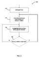
- the controller 106may execute a method 300 for establishing communications with the inverters 202 as illustrated in FIG. 3 .
- the method 300begins with block 302 in which the controller 106 performs various initialization procedures. Such initialization procedures may include initialization of registers and devices, loading of firmware and software, and/or other procedures required to configure the controller 106 for communicating with the inverters 202 .
- the controller 106performs a discovery process to identify each inverter 202 of the array 102 and obtain the information necessary to directly communicate with each inverter 202 .
- the controller 106communicates and/or controls the operation of the modules 104 (i.e., inverters 202 ) in block 306 as needed.
- modules 104may be added or removed from the array 102 . For example, if a module 104 , or a component of the module 104 , becomes defective, the module 104 or component thereof (e.g., inverter 202 ) may be replaced. Additionally, based on the change of power requirements, modules 104 may be added or removed from the array 102 over time.
- the controller 106determines if the module array has been modified in block 308 . If so, the method 300 loops back to block 304 wherein the controller 106 performs the discovery process again to determine the identity of each module 104 (i.e., inverter 202 ). If not, the method 300 loops back to block 306 wherein the controller 106 continues to communicate with the modules 104 as needed.
- the controller 106may determine that the array 102 has been modified based on a direct input supplied to the controller 106 (e.g., an installer informing the controller 106 that a module 104 has been added), based on a failure to communicate with one or more modules 104 , or based on some other criteria.
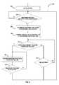
- the method 400begins with block 402 in which the controller 106 determines an initial response time window length.
- the response time windowrepresents a length of time during which the inverters 202 of the modules 104 may respond to a response request transmitted by the controller 106 as discussed in more detail below.
- the controller 106may use any suitable algorithm to determine the initial length of the response time window.
- the controller 106is configured to determine the length of the response time window based on the length of time required for an inverter 202 to transmit the response to the controller 106 multiplied by the expected maximum number of modules 104 in the array 102 . For example, if the inverter 202 requires 500 milliseconds to transmit the response to the controller 106 and the expected maximum number of modules 104 in the array 102 is determined to be 200 , the controller 106 may set the initial length of the response time window to about 100 seconds (i.e., 500 milliseconds*200 modules).
- the length of time required by the inverter 202 to transmit the response to the controller 106may be based on or otherwise affected by the communication protocol used, the communication circuitry used, the data size of the response, and/or other parameters.
- the expected maximum number of modules 104 in the array 102may be an arbitrary maximum number or based on an estimated maximum size of the array 102 (e.g., based on a maximum physical and/or electrical capacity).
- the controller 106may be configured to simply use an arbitrary, large length of time for the initial response time window.
- the controller 106broadcasts a response request, which is received by each of the inverters 202 .
- the response requestincludes the length of the response time window determined in block 406 .
- the response requestprompts each of the inverters 202 to respond to the request by transmitting identification data related to the respective inverter 202 to the controller 106 .
- the controller 106determines whether a response has been received from one of the inverters 202 in response to the response request. If so, the controller 208 records the identification data received in the response from the inverter 202 . For example, the controller 208 may store the identification data in the memory 222 or other storage device.
- the identification datauniquely identifies the inverter 202 from the other inverters of the array 102 and allows the controller 208 to directly communicate with the responding inverter 202 (e.g., the identification data may include a MAC address associated with the responding inverter 202 ).
- the controller 106determines whether the response time window has expired. If not, the method 400 loops back to block 406 wherein the controller 106 again monitors for responses from the inverters 202 . However, if the controller 106 determines that the response time window has expired in block 410 , the controller 106 determines if at least one response was received from an inverter 202 in the last response time window in block 412 . If so, the controller 106 transmits an acknowledgment to each of the responding inverters 202 in block 414 .
- the acknowledgmentmay be embodied as any type of communication capable of informing the responding inverters 202 that the controller 106 has received their respective responses. As discussed in more detail below in regard to FIG. 5 , the acknowledgement may also prompt the responding inverters 202 to ignore subsequent response requests from the controller 106 .
- the controller 106adjusts the length of the response time window.
- the controller 106is configured to decrease the length of the response time window in block 416 .
- the controller 106may be configured to decrease the length of the response time window by a predetermined multiple of the length of time required by an inverter 202 to transmit a response to the response request.
- the controller 106may be configured to decrease the response time window by a multiple of 500 milliseconds (e.g., 500 ms, 1000 ms, 1500 ms, etc.), which was the length of time required for an inverter 202 to respond.
- a minimum response time window lengthmay be used if the adjusted would reduce the length of the response time window below a minimum length.
- the controller 106may decrease the response window time by an arbitrary, predetermined amount. Additionally, in some embodiments, the adjustment made to the response time window in block 416 may be based on other criteria. For example, the adjustment may be based on the number of data collisions detected by the controller 106 in the previous response time window or on the expected remaining number of non-responding inverters 202 . In such embodiments, the length of the response time window may be decreased, may be increased, or may remain the same.
- the controller 106resets a time-out counter.
- the time-out counteris used to estimate when all of the inverters 202 of the array 102 have been discovered and responded to the controller 106 . As such, if at least one response was received in the current response time window, the controller 106 resets the time-out counter in block 418 . After the time-out counter is reset in block 418 , the method 400 loops back to block 404 in which the controller 106 broadcasts another response request, which includes the adjusted response time window length.
- the method 400advances to block 420 .
- the controller 106increments the time-out counter. As discussed above, the time-out counter is used to estimate when all of the inverters 202 of the array 102 have been discovered. As such, in block 422 , the controller 106 determines if the time-out counter is equal to a predetermined threshold value. If not, the method 400 advances to block 416 in which the response time window length is adjusted.
- the controller 106determines that all of the inverters 202 of the array 102 have been discovered and ends the discovery process in block 424 .
- the predetermined threshold valueis set to three. As such, the controller 106 will continue to broadcast response requests until no response is received from an inverter 202 in three consecutive response time windows.
- other values for the predetermined threshold valuemay be used in other embodiments.
- each of the inverters 202 of the modules 104 of the array 102may execute a method 500 for establishing communication with the alternative energy module array controller 106 .
- the method 500begins with block 502 in which the inverter 202 performs various initialization procedures. Such initialization procedures may include initialization of registers and devices, loading of firmware and software, and/or other procedures required to configure the inverter 202 for communicating with the controller 106 .
- the inverter 202determines whether a response request was received from the controller 106 . As discussed above in regard to FIG. 4 , the response request is broadcast by the controller 106 and, as such, received by each inverter 202 . If no response request has been received, the method 500 loops back to block 504 in which the inverter 202 continues to monitor for a broadcast from the controller 106 .
- the inverter 202determines a response time to respond to the response request in block 506 .
- the response timeis based on the length of the response time window, which is included in the response request received from the controller 106 .
- the inverter 202is configured to randomly determine a response time within the response time window at which to send its response to the controller 106 . Such response times may be multiples of the length of time required by the inverter 202 to send the response to the controller 106 .
- the response time determine by the inverter 202 in block 506may be a random integer multiple of 500 ms, which was the estimated time to transmit the response to the controller 106 .
- each of the inverters 202randomly selects a timeslot of the response time window in which to send its response to the controller 106 .
- the responses from the inverters 202are spread across the response time window, thereby reducing the likelihood of communication collisions.
- the inverter 202transmits a response to the controller 106 at the response time determined in block 506 .
- the responseincludes identification data that uniquely identifies the responding inverter 202 from the other inverters 202 of the array 102 .
- the identification datamay be used by the controller 106 to send direct communications (e.g., a unicast) to the responding inverter 202 .
- the identification datamay include the MAC address of the responding inverter 202 .
- the inverter 202determines if an acknowledgment has been received from the controller 106 in block 510 . If no acknowledgement has been received, the inverter 202 determines if a wait period has expired in block 512 . If not, the inverter 202 continues to monitor for an acknowledgement from the controller 106 in blocks 510 , 512 until an acknowledgment is received or the wait period expires.
- the wait periodmay be an arbitrary wait period, based on the response window time, or some other criteria. After the wait period expires (or other wait period lapses) with no acknowledgment received, the method 500 loops back to block 504 in which the inverter continues to monitor for response requests from the controller 106 .
- the method 500advances to block 514 .
- the inverter 202ignores any subsequent response requests received from the controller 106 . In this way, the amount of response traffic is reduced over time as the number of acknowledged inverters increases.
- the discovery processmay be restarted at a later time.
- the inverter 202determines if the discovery process has been reinitiated in block 516 . If not, the method 500 loops back to block 514 wherein the controller continues to ignore response requests from the controller 106 . However, if the discovery process has been reinitiated in block 516 , the method 500 loops back to block 504 in which the inverter continues to monitor for response requests from the controller 106 .
- the discovery processmay be reinitiated after a predetermined lapse of time, in response to the array 102 being modified, or based on some other criteria.
Landscapes
- Engineering & Computer Science (AREA)
- Power Engineering (AREA)
- Computer Networks & Wireless Communication (AREA)
- Signal Processing (AREA)
- Inverter Devices (AREA)
- Cable Transmission Systems, Equalization Of Radio And Reduction Of Echo (AREA)
- Small-Scale Networks (AREA)
- Data Exchanges In Wide-Area Networks (AREA)
Abstract
Description
Claims (30)
Priority Applications (4)
| Application Number | Priority Date | Filing Date | Title |
|---|---|---|---|
| US12/902,046US9160408B2 (en) | 2010-10-11 | 2010-10-11 | System and method for establishing communication with an array of inverters |
| PCT/US2011/055685WO2012051142A2 (en) | 2010-10-11 | 2011-10-11 | System and method for establishing communication with an array of inverters |
| US14/872,886US10033221B2 (en) | 2010-10-11 | 2015-10-01 | System and method for establishing communication with an array of inverters |
| US16/039,080US10483795B2 (en) | 2010-10-11 | 2018-07-18 | System and method for establishing communication with an array of inverters |
Applications Claiming Priority (1)
| Application Number | Priority Date | Filing Date | Title |
|---|---|---|---|
| US12/902,046US9160408B2 (en) | 2010-10-11 | 2010-10-11 | System and method for establishing communication with an array of inverters |
Related Child Applications (1)
| Application Number | Title | Priority Date | Filing Date |
|---|---|---|---|
| US14/872,886DivisionUS10033221B2 (en) | 2010-10-11 | 2015-10-01 | System and method for establishing communication with an array of inverters |
Publications (2)
| Publication Number | Publication Date |
|---|---|
| US20120089260A1 US20120089260A1 (en) | 2012-04-12 |
| US9160408B2true US9160408B2 (en) | 2015-10-13 |
Family
ID=45925760
Family Applications (3)
| Application Number | Title | Priority Date | Filing Date |
|---|---|---|---|
| US12/902,046Active2032-07-05US9160408B2 (en) | 2010-10-11 | 2010-10-11 | System and method for establishing communication with an array of inverters |
| US14/872,886Active2031-09-26US10033221B2 (en) | 2010-10-11 | 2015-10-01 | System and method for establishing communication with an array of inverters |
| US16/039,080ActiveUS10483795B2 (en) | 2010-10-11 | 2018-07-18 | System and method for establishing communication with an array of inverters |
Family Applications After (2)
| Application Number | Title | Priority Date | Filing Date |
|---|---|---|---|
| US14/872,886Active2031-09-26US10033221B2 (en) | 2010-10-11 | 2015-10-01 | System and method for establishing communication with an array of inverters |
| US16/039,080ActiveUS10483795B2 (en) | 2010-10-11 | 2018-07-18 | System and method for establishing communication with an array of inverters |
Country Status (2)
| Country | Link |
|---|---|
| US (3) | US9160408B2 (en) |
| WO (1) | WO2012051142A2 (en) |
Cited By (23)
| Publication number | Priority date | Publication date | Assignee | Title |
|---|---|---|---|---|
| US10003300B2 (en) | 2015-10-09 | 2018-06-19 | Sunpower Corporation | Photovoltaic management and module-level power electronics |
| USD822890S1 (en) | 2016-09-07 | 2018-07-10 | Felxtronics Ap, Llc | Lighting apparatus |
| USD832494S1 (en) | 2017-08-09 | 2018-10-30 | Flex Ltd. | Lighting module heatsink |
| USD832495S1 (en) | 2017-08-18 | 2018-10-30 | Flex Ltd. | Lighting module locking mechanism |
| USD833061S1 (en) | 2017-08-09 | 2018-11-06 | Flex Ltd. | Lighting module locking endcap |
| USD846793S1 (en) | 2017-08-09 | 2019-04-23 | Flex Ltd. | Lighting module locking mechanism |
| USD862777S1 (en) | 2017-08-09 | 2019-10-08 | Flex Ltd. | Lighting module wide distribution lens |
| USD862778S1 (en) | 2017-08-22 | 2019-10-08 | Flex Ltd | Lighting module lens |
| USD872319S1 (en) | 2017-08-09 | 2020-01-07 | Flex Ltd. | Lighting module LED light board |
| USD877964S1 (en) | 2017-08-09 | 2020-03-10 | Flex Ltd. | Lighting module |
| US10652743B2 (en) | 2017-12-21 | 2020-05-12 | The Chamberlain Group, Inc. | Security system for a moveable barrier operator |
| USD888323S1 (en) | 2017-09-07 | 2020-06-23 | Flex Ltd | Lighting module wire guard |
| US10769318B2 (en)* | 2017-02-17 | 2020-09-08 | Sunpower Corporation | Systems and method for determining solar panel placement and energy output |
| US10775030B2 (en) | 2017-05-05 | 2020-09-15 | Flex Ltd. | Light fixture device including rotatable light modules |
| US10862924B2 (en) | 2005-06-30 | 2020-12-08 | The Chamberlain Group, Inc. | Method and apparatus to facilitate message transmission and reception using different transmission characteristics |
| USRE48433E1 (en) | 2005-01-27 | 2021-02-09 | The Chamberlain Group, Inc. | Method and apparatus to facilitate transmission of an encrypted rolling code |
| US10944559B2 (en) | 2005-01-27 | 2021-03-09 | The Chamberlain Group, Inc. | Transmission of data including conversion of ternary data to binary data |
| US10997810B2 (en) | 2019-05-16 | 2021-05-04 | The Chamberlain Group, Inc. | In-vehicle transmitter training |
| US11074773B1 (en) | 2018-06-27 | 2021-07-27 | The Chamberlain Group, Inc. | Network-based control of movable barrier operators for autonomous vehicles |
| US11423717B2 (en) | 2018-08-01 | 2022-08-23 | The Chamberlain Group Llc | Movable barrier operator and transmitter pairing over a network |
| US11791633B2 (en) | 2011-07-11 | 2023-10-17 | Generac Power Systems, Inc. | Systems and methods for increasing output current quality, output power, and reliability of grid-interactive inverters |
| US20240193319A1 (en)* | 2017-02-17 | 2024-06-13 | Sunpower Corporation | Systems and method for determining solar panel placement and energy output |
| US12149618B2 (en) | 2005-01-27 | 2024-11-19 | The Chamberlain Group Llc | Method and apparatus to facilitate transmission of an encrypted rolling code |
Families Citing this family (22)
| Publication number | Priority date | Publication date | Assignee | Title |
|---|---|---|---|---|
| US8462518B2 (en) | 2009-10-12 | 2013-06-11 | Solarbridge Technologies, Inc. | Power inverter docking system for photovoltaic modules |
| US8193788B2 (en) | 2011-04-27 | 2012-06-05 | Solarbridge Technologies, Inc. | Method and device for controlling a configurable power supply to provide AC and/or DC power output |
| KR101779614B1 (en)* | 2011-06-08 | 2017-09-18 | 엘에스산전 주식회사 | Inverter communication system |
| SE1251373A1 (en)* | 2012-12-04 | 2014-06-05 | BAE Systems Hägglunds Aktiebolag | Apparatus and method for distributing electrical energy |
| FR2999339A1 (en)* | 2012-12-12 | 2014-06-13 | Crosslux | METHOD FOR IDENTIFYING PHOTOVOLTAIC MODULES IN A PHOTOVOLTAIC INSTALLATION |
| JP6175272B2 (en)* | 2013-01-17 | 2017-08-02 | 田淵電機株式会社 | Control device and control system in solar power generation device |
| US10833629B2 (en) | 2013-03-15 | 2020-11-10 | Technology Research, Llc | Interface for renewable energy system |
| US9564756B2 (en) | 2013-03-15 | 2017-02-07 | Technology Research, Llc | Interface for renewable energy system |
| US9584044B2 (en) | 2013-03-15 | 2017-02-28 | Sunpower Corporation | Technologies for converter topologies |
| CN104242701B (en)* | 2013-06-13 | 2017-06-16 | 台达电子工业股份有限公司 | DC-AC converter, micro inverter and solar system thereof |
| CN104244467A (en)* | 2013-06-13 | 2014-12-24 | 台达电子工业股份有限公司 | Power line routing system and routing method thereof |
| US9876360B2 (en) | 2015-02-02 | 2018-01-23 | Technology Research, Llc | Interface for renewable energy system |
| AR107145A1 (en) | 2015-12-18 | 2018-03-28 | Southwire Co Llc | CURRENT INVERSORS OF SOLAR CELLS INTEGRATED TO A CABLE |
| US9634723B1 (en)* | 2015-12-18 | 2017-04-25 | Sunpower Corporation | Communication between photovoltaic devices on a shared power line |
| EP3535825A1 (en) | 2016-11-07 | 2019-09-11 | Southwire Company, LLC | Dead band direct current converter |
| US11251621B1 (en) | 2017-08-03 | 2022-02-15 | Southwire Company, Llc | Solar power generation system |
| US11438988B1 (en) | 2017-08-11 | 2022-09-06 | Southwire Company, Llc | DC power management system |
| EP3745556B1 (en)* | 2019-05-29 | 2022-02-23 | ABB Schweiz AG | A computer-implemented method for wireless communicating at local level with the control nodes of an electric system |
| WO2021021961A1 (en)* | 2019-07-29 | 2021-02-04 | Enphase Energy, Inc. | Protocol for multi-master communication coordination on shared media channel |
| CN110572184B (en)* | 2019-08-02 | 2021-03-05 | 华为技术有限公司 | Power generation system and communication device for power generation system |
| JP7502243B2 (en)* | 2021-09-15 | 2024-06-18 | 株式会社東芝 | Inverter, power supply device, energy control method, and program |
| EP4270709A1 (en)* | 2022-04-29 | 2023-11-01 | FRONIUS INTERNATIONAL GmbH | Energy management system |
Citations (163)
| Publication number | Priority date | Publication date | Assignee | Title |
|---|---|---|---|---|
| US3670230A (en) | 1970-12-21 | 1972-06-13 | Ibm | Active filter capacitor for power supply switching regulators |
| US4114048A (en) | 1976-03-10 | 1978-09-12 | Westinghouse Electric Corp. | Load balancing system for ups rectifiers |
| US4217633A (en) | 1978-06-09 | 1980-08-12 | The United States Of America As Represented By The Administrator Of The National Aeronautics And Space Administration | Solar cell system having alternating current output |
| US4277692A (en) | 1979-06-04 | 1981-07-07 | Tab Products Company | Continuous power source with bi-directional converter |
| US4287465A (en) | 1978-10-09 | 1981-09-01 | Saft-Societe Des Accumulateurs Fixes Et De Traction | Apparatus for regulating the charging of a storage battery |
| US4651265A (en) | 1985-07-29 | 1987-03-17 | Westinghouse Electric Corp. | Active power conditioner system |
| US4661758A (en) | 1980-02-22 | 1987-04-28 | Lane S. Garrett | Solar power supply and battery charging circuit |
| US4707774A (en) | 1985-10-31 | 1987-11-17 | Mitsubishi Denki Kabushiki Kaisha | Flywheel power source apparatus |
| US4709318A (en) | 1986-10-22 | 1987-11-24 | Liebert Corporation | UPS apparatus with control protocols |
| US4719550A (en) | 1986-09-11 | 1988-01-12 | Liebert Corporation | Uninterruptible power supply with energy conversion and enhancement |
| US4725740A (en) | 1984-08-23 | 1988-02-16 | Sharp Kabushiki Kaisha | DC-AC converting arrangement for photovoltaic system |
| US5041959A (en) | 1990-08-14 | 1991-08-20 | General Electric Company | Control system for a current source converter supplying an AC bus |
| US5148043A (en) | 1989-07-25 | 1992-09-15 | Kabushiki Kaisha Toshiba | Uninterruptible power supply diagnosing remaining battery capacity during normal external power source operation |
| US5160851A (en) | 1990-08-28 | 1992-11-03 | Nynex Corporation | Rechargeable back-up battery system including a number of battery cells having float voltage exceeding maximum load voltage |
| US5191519A (en) | 1991-03-27 | 1993-03-02 | Kabushiki Kaisha Toshiba | Current sharing control in a parallel inverter system |
| US5309073A (en) | 1991-10-21 | 1994-05-03 | Hitachi, Ltd. | Electric vehicle control device |
| US5343380A (en) | 1992-11-17 | 1994-08-30 | Champlin Keith S | Method and apparatus for suppressing time-varying signals in batteries undergoing charging or discharging |
| US5473528A (en) | 1991-09-18 | 1995-12-05 | Kabushiki Kaisha Toshiba | Parallel connection of different types of AC power supplies of differing capacities |
| US5668464A (en) | 1994-10-26 | 1997-09-16 | The Board Of Trustees Of The University Of Illinois | Feedforward active filter for output ripple cancellation in switching power converters |
| US5684385A (en) | 1995-03-24 | 1997-11-04 | France Telecom | Customized storage, high voltage, photovoltaic power station |
| US5721481A (en) | 1995-03-08 | 1998-02-24 | International Business Machines Corp. | Battery charger for an electronic device and a spare battery |
| US5745356A (en) | 1996-06-25 | 1998-04-28 | Exide Electronics Corporation | Independent load sharing of AC power systems connected in parallel |
| US5796182A (en) | 1996-06-27 | 1998-08-18 | Martin; Richard A. | Capacator storage circuit for sustaining a DC converter |
| US5801519A (en) | 1996-06-21 | 1998-09-01 | The Board Of Trustees Of The University Of Illinois | Self-excited power minimizer/maximizer for switching power converters and switching motor drive applications |
| US5886890A (en) | 1996-06-24 | 1999-03-23 | Sanyo Electric Co., Ltd. | Power-supply system involving system interconnection |
| US5929537A (en) | 1997-06-30 | 1999-07-27 | Sundstrand Corporation | PMG main engine starter/generator system |
| US5978236A (en) | 1997-01-31 | 1999-11-02 | Silverline Power Conversion Llc | Uninterruptible power supply with direction of DC electrical energy depending on predetermined ratio |
| US5982645A (en) | 1992-08-25 | 1999-11-09 | Square D Company | Power conversion and distribution system |
| US6046402A (en) | 1998-05-21 | 2000-04-04 | Motorola, Inc. | Solar hybrid electrical powering devices for pulse discharge applications |
| US6154379A (en) | 1998-07-16 | 2000-11-28 | Tdk Corporation | Electric power conversion device |
| US6157168A (en) | 1999-10-29 | 2000-12-05 | International Business Machines Corporation | Secondary power supply for an uninterruptible power system |
| US6180868B1 (en) | 1998-06-12 | 2001-01-30 | Canon Kabushiki Kaisha | Solar cell module, solar cell module string, solar cell system, and method for supervising said solar cell module or solar cell module string |
| DE20012131U1 (en) | 2000-07-13 | 2001-02-22 | Pätz, Werner, Dipl.-Ing., 86928 Hofstetten | Solar generator |
| US6201319B1 (en) | 1998-07-14 | 2001-03-13 | American Power Conversion | Uninterruptible power supply |
| US6201180B1 (en) | 1999-04-16 | 2001-03-13 | Omnion Power Engineering Corp. | Integrated photovoltaic system |
| US6225708B1 (en) | 1998-06-05 | 2001-05-01 | International Business Machine Corporation | Uninterruptable power supply |
| US6268559B1 (en) | 1999-03-24 | 2001-07-31 | Kaneka Corporation | Photovoltaic generation system, wiring apparatus for photovoltaic generation system, and wiring structure therefor |
| US6285572B1 (en) | 1999-04-20 | 2001-09-04 | Sanyo Electric Co., Ltd. | Method of operating a power supply system having parallel-connected inverters, and power converting system |
| US6291764B1 (en) | 1999-03-24 | 2001-09-18 | Sanyo Electronics Co., Ltd. | Photovoltaic power generation device |
| US6311279B1 (en) | 1998-10-27 | 2001-10-30 | Compaq Computer Corporation | Network node with internal battery backup |
| US20010043050A1 (en) | 1998-08-07 | 2001-11-22 | Carl Fisher | Apparatus and method for initial charging, self-starting, and operation of a power supply with an intermittent and/or variable energy source and a rechargeable energy storage device |
| US20020017822A1 (en) | 2000-07-14 | 2002-02-14 | Tokihiro Umemura | Power control device with electric double layer capacitor unit cells |
| US6356471B1 (en) | 2000-07-10 | 2002-03-12 | Powerware Corporation | Dynamic feedback adaptive control system and method for paralleling electric power sources and an uninterruptible power supply including same |
| US6369461B1 (en) | 2000-09-01 | 2002-04-09 | Abb Inc. | High efficiency power conditioner employing low voltage DC bus and buck and boost converters |
| US6381157B2 (en) | 2000-01-06 | 2002-04-30 | Axel Akerman A/S | Independent load sharing between parallel inverter units in an AC power system |
| US6445089B1 (en) | 2000-09-22 | 2002-09-03 | Sanyo Denki Co. Ltd. | Uninterruptible power system |
| US6489755B1 (en) | 2000-09-18 | 2002-12-03 | Adtran, Inc. | Active ripple and noise filter for telecommunication equipment powering |
| US20020196026A1 (en) | 2001-06-07 | 2002-12-26 | Matsushita Electric Industrial Co., Ltd. | Method and apparatus for controlling residual battery capacity of secondary battery |
| US6563234B2 (en) | 2000-02-03 | 2003-05-13 | Sumitomo Electric Industries, Ltd. | Power system stabilization system and method employing a rechargeable battery system |
| US6605881B2 (en) | 2000-10-25 | 2003-08-12 | Canon Kabushiki Kaisha | AC interconnection apparatus supplying AC power from a commercial power system and from a solar cell |
| US6614132B2 (en) | 2001-11-30 | 2003-09-02 | Beacon Power Corporation | Multiple flywheel energy storage system |
| US6624533B1 (en) | 1999-08-04 | 2003-09-23 | Westerbeke Corporation | Controlling generator power |
| US6657321B2 (en) | 2001-10-02 | 2003-12-02 | General Electric Company | Direct current uninterruptible power supply method and system |
| WO2004008619A2 (en) | 2002-07-15 | 2004-01-22 | Koninklijke Philips Electronics N.V. | Inverter |
| US6700802B2 (en) | 2000-02-14 | 2004-03-02 | Aura Systems, Inc. | Bi-directional power supply circuit |
| CA2353422C (en) | 2000-07-24 | 2004-03-02 | Chippower.Com, Inc. | High frequency dc to ac inverter |
| NL1021582C2 (en) | 2002-10-04 | 2004-04-06 | Stichting Energie | Modularly assembled photovoltaic device. |
| NL1021591C2 (en) | 2002-10-05 | 2004-04-06 | Energieonderzoek Ct Petten Ecn | Photovoltaic device without wiring. |
| US6727602B2 (en) | 2001-01-29 | 2004-04-27 | Broadcom Corporation | Power supply for controlled parallel charging and discharging of batteries |
| US6750391B2 (en) | 2001-10-25 | 2004-06-15 | Sandia Corporation | Aternating current photovoltaic building block |
| US20040128387A1 (en)* | 2002-12-27 | 2004-07-01 | Kwan Wu Chin | Broadcasting information in ad-hoc network clusters between pseudo-random time intervals |
| US6765315B2 (en) | 2001-03-14 | 2004-07-20 | International Power Systems, Inc. | Bi-directional regulator/converter with buck/boost by fuzzy logic control |
| US6770984B2 (en) | 2001-08-28 | 2004-08-03 | Delta Electronics Inc. | Electronic voltage regulator with switching control device and control method for stabilizing output voltage |
| US6795322B2 (en) | 1998-12-25 | 2004-09-21 | Hitachi, Ltd. | Power supply with uninterruptible function |
| WO2004100348A1 (en) | 2003-05-06 | 2004-11-18 | Enecsys Limited | Power supply circuits |
| US6838611B2 (en) | 2000-09-29 | 2005-01-04 | Canon Kabushiki Kaisha | Solar battery module and power generation apparatus |
| US6847196B2 (en) | 2002-08-28 | 2005-01-25 | Xantrex Technology Inc. | Method and apparatus for reducing switching losses in a switching circuit |
| US6881509B2 (en) | 2001-12-19 | 2005-04-19 | Abb Research Ltd. | Fuel cell system power control method and system |
| US6882063B2 (en) | 2000-07-28 | 2005-04-19 | International Power Systems, Inc. | DC to DC converter and power management system |
| US6950323B2 (en) | 2001-03-09 | 2005-09-27 | Fronius International Gmbh | Method for regulating an inverter system |
| US20050213272A1 (en) | 2004-03-23 | 2005-09-29 | Canon Kabushiki Kaisha | Power generation system, and administration apparatus and administration method of power generation system |
| US20060067222A1 (en)* | 2004-09-30 | 2006-03-30 | Kyocera Corporation | Data communication apparatus |
| US20060067137A1 (en) | 2004-09-03 | 2006-03-30 | Cambridge Semiconductor Limited | Semiconductor device and method of forming a semiconductor device |
| US20060083039A1 (en) | 2003-01-31 | 2006-04-20 | Oliveira Marcos P D | Power supply system with single phase or multiple phase inverters operating in parallel |
| GB2419968A (en) | 2004-11-08 | 2006-05-10 | Enecsys Ltd | Regulating the voltage fed to a power converter |
| WO2006048688A1 (en) | 2004-11-08 | 2006-05-11 | Enecsys Limited | Power conditioning unit |
| US20060122857A1 (en)* | 2001-03-22 | 2006-06-08 | Decotiis Allen R | Computer systems, methods, computer models, and computer software for enhancing a customer list for a targeted marketing campaign |
| US7072195B2 (en) | 2002-02-22 | 2006-07-04 | Xantrex Technology Inc. | Modular AC voltage supply and algorithm for controlling the same |
| GB2421847A (en) | 2004-11-08 | 2006-07-05 | Enecsys Ltd | Integrated circuits for power conditioning |
| US7091707B2 (en) | 2003-09-29 | 2006-08-15 | Xantrex Technology, Inc. | Method and apparatus for controlling power drawn from an energy converter |
| US7193872B2 (en) | 2005-01-28 | 2007-03-20 | Kasemsan Siri | Solar array inverter with maximum power tracking |
| US20070133241A1 (en) | 2003-05-06 | 2007-06-14 | Asim Mumtaz | Power supply circuits |
| US7233130B1 (en) | 2005-08-05 | 2007-06-19 | Rf Micro Devices, Inc. | Active ripple reduction switched mode power supplies |
| EP1803161A1 (en) | 2004-09-10 | 2007-07-04 | Element Six Limited | Switching device |
| WO2007080429A2 (en) | 2006-01-13 | 2007-07-19 | Enecsys Limited | Power conditioning unit |
| EP1837985A2 (en) | 2006-03-23 | 2007-09-26 | PVI Solutions Inc. | Mehtod and apparatus for converting direct surrent to alternating current |
| US7289341B2 (en) | 2004-12-14 | 2007-10-30 | Advanced Energy Industries, Inc. | Power supply adaptive feedforward control circuit |
| GB2439648A (en) | 2006-06-29 | 2008-01-02 | Enecys Ltd | A DC to AC power converter |
| US7319313B2 (en) | 2005-08-10 | 2008-01-15 | Xantrex Technology, Inc. | Photovoltaic DC-to-AC power converter and control method |
| US7339287B2 (en) | 2002-06-23 | 2008-03-04 | Powerlynx A/S | Power converter |
| US20080055952A1 (en) | 2006-06-29 | 2008-03-06 | Lesley Chisenga | DC to AC Power Converter |
| US20080078436A1 (en) | 2006-09-28 | 2008-04-03 | Jack Nachamkin | Integrated voltaic energy system |
| US7365998B2 (en) | 2005-09-30 | 2008-04-29 | Intel Corporation | Unregulated isolated DC/DC converter with ripple control |
| US7405494B2 (en) | 2004-07-07 | 2008-07-29 | Eaton Corporation | AC power supply apparatus, methods and computer program products using PWM synchronization |
| US20080266922A1 (en) | 2004-11-08 | 2008-10-30 | Asim Mumtaz | Integrated Circuits and Power Supplies |
| US20080272279A1 (en) | 2007-05-04 | 2008-11-06 | Xantrex International | Method and apparatus for producing an indication of solar panel condition |
| US20080283118A1 (en) | 2007-05-17 | 2008-11-20 | Larankelo, Inc. | Photovoltaic ac inverter mount and interconnect |
| US7463500B2 (en) | 2003-02-21 | 2008-12-09 | Xantrex Technology, Inc. | Monopolar DC to bipolar DC to AC converter |
| US20080304296A1 (en) | 2007-06-06 | 2008-12-11 | General Electric Company | DC-DC and DC-AC power conversion system |
| US20090000654A1 (en) | 2007-05-17 | 2009-01-01 | Larankelo, Inc. | Distributed inverter and intelligent gateway |
| US20090020151A1 (en) | 2007-07-16 | 2009-01-22 | Pvi Solutions, Inc. | Method and apparatus for converting a direct current to alternating current utilizing a plurality of inverters |
| US7502697B2 (en) | 2006-09-28 | 2009-03-10 | Programmable Division Of Xantrex Technology, Inc. | AC output power supply with digital feedback loop |
| US20090066357A1 (en) | 2007-09-06 | 2009-03-12 | Enphase Energy, Inc. | Method and apparatus for detecting impairment of a solar array |
| US20090079383A1 (en) | 2007-09-26 | 2009-03-26 | Enphase Energy, Inc. | Method and apparatus for power conversion with maximum power point tracking and burst mode capability |
| US20090080226A1 (en) | 2007-09-26 | 2009-03-26 | Enphase Energy, Inc. | Method and apparatus for maximum power point tracking in power conversion based on dual feedback loops and power ripples |
| US20090086514A1 (en) | 2007-09-28 | 2009-04-02 | Enphase Energy, Inc. | Method and apparatus for providing power conversion using an interleaved flyback converter with automatic balancing |
| US20090084426A1 (en) | 2007-09-28 | 2009-04-02 | Enphase Energy, Inc. | Universal interface for a photovoltaic module |
| US20090097283A1 (en) | 2007-10-11 | 2009-04-16 | Krein Philip T | Methods for Minimizing Double-Frequency Ripple Power in Single-Phase Power Conditioners |
| US7531993B2 (en) | 2007-08-29 | 2009-05-12 | Cambridge Semiconductor Limited | Half bridge circuit and method of operating a half bridge circuit |
| US20090147554A1 (en) | 2007-12-05 | 2009-06-11 | Solaredge, Ltd. | Parallel connected inverters |
| US7551460B2 (en) | 2006-05-23 | 2009-06-23 | Cambridge Semiconductor Limited | Switch mode power supply controllers |
| GB2455755A (en) | 2007-12-20 | 2009-06-24 | Enecsys Ltd | Grid synchronizer for inverter |
| GB2455753A (en) | 2007-12-20 | 2009-06-24 | Enecsys Ltd | Blind with photovoltaic panels |
| WO2009081205A2 (en) | 2007-12-20 | 2009-07-02 | Enecsys Limited | Grid synchronisation |
| US20090184695A1 (en) | 2008-01-18 | 2009-07-23 | Programmable Division Of Xantrex Technology, Inc. | Method and system for rms computation on digitized samples |
| US20090200994A1 (en) | 2008-02-12 | 2009-08-13 | Enphase Energy, Inc. | Method and apparatus for distributed var compensation |
| US7577005B2 (en) | 2004-12-16 | 2009-08-18 | Fronius International Gmbh | Method for recognizing the load of an island inverter and island inverter |
| US20090225574A1 (en) | 2008-03-06 | 2009-09-10 | Enphase Energy, Inc. | Method and apparatus for a leakage energy recovery circuit |
| US20090230782A1 (en) | 2008-03-11 | 2009-09-17 | Enphase Energy, Inc. | Apparatus for phase rotation for a three-phase AC circuit |
| US7592789B2 (en) | 2005-10-31 | 2009-09-22 | Chil Semiconductor Corporation | Power supply and related circuits |
| US20090244929A1 (en) | 2008-03-26 | 2009-10-01 | Enphase Energy, Inc. | Method and apparatus for extending zero-voltage swiitching range in a DC to DC converter |
| US20090242272A1 (en) | 2008-03-28 | 2009-10-01 | Greenray, Inc. | Electrical cable harness and assembly for transmitting ac electrical power |
| US20090244947A1 (en) | 2008-03-26 | 2009-10-01 | Enphase Energy, Inc. | Method and apparatus for resetting a silicon controlled rectifier bridge |
| US20090242011A1 (en) | 2008-02-19 | 2009-10-01 | Photowatt International | Installation of telecontrolled photovoltaic modules |
| US20090244939A1 (en) | 2008-03-26 | 2009-10-01 | Enphase Energy, Inc. | Method and apparatus for resetting silicon controlled rectifiers in a hybrid bridge |
| US20090243587A1 (en) | 2008-03-26 | 2009-10-01 | Enphase Energy, Inc. | Method and apparatus for measuring AC voltages |
| US7609040B1 (en) | 2005-10-31 | 2009-10-27 | Chil Semiconductor Corporation | Power supply and related circuits |
| WO2009134756A1 (en) | 2008-04-29 | 2009-11-05 | Cirrus Logic, Inc. | Cascaded switching power converter for coupling a photovoltaic energy source to power mains |
| US20090296348A1 (en) | 2008-05-20 | 2009-12-03 | Miles Clayton Russell | Ac photovoltaic module and inverter assembly |
| US7638899B2 (en) | 2006-03-10 | 2009-12-29 | Eaton Corporation | Nested redundant uninterruptible power supply apparatus and methods |
| US7646116B2 (en) | 2008-05-22 | 2010-01-12 | Petra Solar Inc. | Method and system for balancing power distribution in DC to DC power conversion |
| US7660139B2 (en) | 2004-06-21 | 2010-02-09 | Xantrex International | Output power factor control of pulse-width modulated inverter |
| US7693174B2 (en)* | 2005-06-17 | 2010-04-06 | Sony Corporation | Communication collision avoidance system |
| US20100088052A1 (en) | 2008-10-08 | 2010-04-08 | Xantrex Technology, Inc. | Contactor Status Detection in Power Inverters |
| US20100085035A1 (en) | 2008-10-08 | 2010-04-08 | Enphase Energy, Inc. | Method and apparatus for determining AC voltage waveform anomalies |
| US20100091532A1 (en) | 2008-10-10 | 2010-04-15 | Enphase Energy, Inc. | Method and apparatus for improved burst mode during power conversion |
| US20100106438A1 (en) | 2008-10-16 | 2010-04-29 | Enphase Energy, Inc. | Method and apparatus for determining an operating voltage for preventing photovoltaic cell reverse breakdown during power conversion |
| US7710752B2 (en) | 2006-05-23 | 2010-05-04 | Xantrex Technology Inc. | Transformerless utility-grid-interactive inverter |
| US20100138771A1 (en)* | 2009-10-26 | 2010-06-03 | Vivek Kumar | Method and apparatus for monitoring a power system |
| US7733679B2 (en) | 2003-10-31 | 2010-06-08 | Fronius International Gmbh | Method for setting switching times, in particular idle times, of an inverter based on detected power, and inverter |
| US20100139945A1 (en) | 2008-12-04 | 2010-06-10 | Enphase Energy, Inc. | Mounting rail and power distribution system for use in a photovoltaic system |
| US20100162256A1 (en)* | 2008-12-18 | 2010-06-24 | Alexander Branover | Optimization of application power consumption and performance in an integrated system on a chip |
| US20100175338A1 (en) | 2007-09-24 | 2010-07-15 | Petra Inventum, S.L. | Solar energy-collecting architectural enclosure panel and walkable solar energy-collecting roof |
| US20100180116A1 (en)* | 2008-11-03 | 2010-07-15 | Telcordia Technologies, Inc. | Intrusion-tolerant group management for mobile ad-hoc networks |
| US20100176771A1 (en) | 2009-01-15 | 2010-07-15 | Xantrex Technology Inc. | Perturb voltage as a decreasing non-linear function of converter power |
| US20100181830A1 (en) | 2009-01-21 | 2010-07-22 | Enphase Energy, Inc. | Method and apparatus for characterizing a circuit coupled to an AC line |
| US20100195665A1 (en)* | 2007-09-24 | 2010-08-05 | Plextek Limited | Data acknowledgement apparatus and method |
| US20100195357A1 (en) | 2009-02-05 | 2010-08-05 | Enphase Energy, Inc. | Method and apparatus for determining a corrected monitoring voltage |
| CA2655007A1 (en) | 2009-02-20 | 2010-08-20 | Queen's University At Kingston | Photovoltaic cell inverter |
| US20100222933A1 (en) | 2009-08-18 | 2010-09-02 | Enphase Energy, Inc. | Method and system for distributed energy generator message aggregation |
| US20100263704A1 (en) | 2009-04-16 | 2010-10-21 | Enphase Energy, Inc. | Apparatus for coupling power generated by a photovoltaic module to an output |
| US20100283325A1 (en) | 2007-06-06 | 2010-11-11 | Andrea Marcianesi | Delivery of Electric Power by Means of a Plurality of Parallel Inverters and Control Method Based on Maximum Power Point Tracking |
| US7839022B2 (en) | 2004-07-13 | 2010-11-23 | Tigo Energy, Inc. | Device for distributed maximum power tracking for solar arrays |
| USRE41965E1 (en) | 2003-08-22 | 2010-11-30 | Xantrex Technology Inc. | Bi-directional multi-port inverter with high frequency link transformer |
| US7855906B2 (en) | 2009-10-26 | 2010-12-21 | General Electric Company | DC bus voltage control for two stage solar converter |
| USRE42039E1 (en) | 2003-02-21 | 2011-01-18 | Xantrex Technology Inc. | DC to AC inverter with single-switch bipolar boost circuit |
| US20110019444A1 (en) | 2009-07-23 | 2011-01-27 | Enphase Energy, Inc. | Method and apparatus for detection and control of dc arc faults |
| US20110026282A1 (en) | 2009-07-31 | 2011-02-03 | Chapman Patrick L | Apparatus for converting direct current to alternating current |
| US20110043160A1 (en) | 2009-08-21 | 2011-02-24 | Xantrex Technology Inc. | Ac connected modules with line frequency or voltage variation pattern for energy control |
| US7899632B2 (en) | 2007-07-16 | 2011-03-01 | Enphase Energy, Inc. | Method and apparatus for anti-islanding of distributed power generation systems |
| US20110051820A1 (en) | 2009-08-28 | 2011-03-03 | Enphase Energy, Inc. | Power line communications apparatus |
| US20110130889A1 (en) | 2009-09-18 | 2011-06-02 | Sayed Ali Khajehoddin | Distributed Power Generation Interface |
| US8456877B2 (en)* | 2006-09-28 | 2013-06-04 | Fronius International Gmbh | Data exchange between inverters in an inverter system |
Family Cites Families (2)
| Publication number | Priority date | Publication date | Assignee | Title |
|---|---|---|---|---|
| US8225093B2 (en)* | 2006-12-05 | 2012-07-17 | Qualcomm Incorporated | Providing secure inter-application communication for a mobile operating environment |
| US20090284369A1 (en)* | 2008-05-13 | 2009-11-19 | Qualcomm Incorporated | Transmit power control for a wireless charging system |
- 2010
- 2010-10-11USUS12/902,046patent/US9160408B2/enactiveActive
- 2011
- 2011-10-11WOPCT/US2011/055685patent/WO2012051142A2/enactiveApplication Filing
- 2015
- 2015-10-01USUS14/872,886patent/US10033221B2/enactiveActive
- 2018
- 2018-07-18USUS16/039,080patent/US10483795B2/enactiveActive
Patent Citations (193)
| Publication number | Priority date | Publication date | Assignee | Title |
|---|---|---|---|---|
| US3670230A (en) | 1970-12-21 | 1972-06-13 | Ibm | Active filter capacitor for power supply switching regulators |
| US4114048A (en) | 1976-03-10 | 1978-09-12 | Westinghouse Electric Corp. | Load balancing system for ups rectifiers |
| US4217633A (en) | 1978-06-09 | 1980-08-12 | The United States Of America As Represented By The Administrator Of The National Aeronautics And Space Administration | Solar cell system having alternating current output |
| US4287465A (en) | 1978-10-09 | 1981-09-01 | Saft-Societe Des Accumulateurs Fixes Et De Traction | Apparatus for regulating the charging of a storage battery |
| US4277692A (en) | 1979-06-04 | 1981-07-07 | Tab Products Company | Continuous power source with bi-directional converter |
| US4661758A (en) | 1980-02-22 | 1987-04-28 | Lane S. Garrett | Solar power supply and battery charging circuit |
| US4725740A (en) | 1984-08-23 | 1988-02-16 | Sharp Kabushiki Kaisha | DC-AC converting arrangement for photovoltaic system |
| US4651265A (en) | 1985-07-29 | 1987-03-17 | Westinghouse Electric Corp. | Active power conditioner system |
| US4707774A (en) | 1985-10-31 | 1987-11-17 | Mitsubishi Denki Kabushiki Kaisha | Flywheel power source apparatus |
| US4719550A (en) | 1986-09-11 | 1988-01-12 | Liebert Corporation | Uninterruptible power supply with energy conversion and enhancement |
| US4709318A (en) | 1986-10-22 | 1987-11-24 | Liebert Corporation | UPS apparatus with control protocols |
| US5148043A (en) | 1989-07-25 | 1992-09-15 | Kabushiki Kaisha Toshiba | Uninterruptible power supply diagnosing remaining battery capacity during normal external power source operation |
| US5041959A (en) | 1990-08-14 | 1991-08-20 | General Electric Company | Control system for a current source converter supplying an AC bus |
| US5160851A (en) | 1990-08-28 | 1992-11-03 | Nynex Corporation | Rechargeable back-up battery system including a number of battery cells having float voltage exceeding maximum load voltage |
| US5191519A (en) | 1991-03-27 | 1993-03-02 | Kabushiki Kaisha Toshiba | Current sharing control in a parallel inverter system |
| US5473528A (en) | 1991-09-18 | 1995-12-05 | Kabushiki Kaisha Toshiba | Parallel connection of different types of AC power supplies of differing capacities |
| US5309073A (en) | 1991-10-21 | 1994-05-03 | Hitachi, Ltd. | Electric vehicle control device |
| US5982645A (en) | 1992-08-25 | 1999-11-09 | Square D Company | Power conversion and distribution system |
| US5343380A (en) | 1992-11-17 | 1994-08-30 | Champlin Keith S | Method and apparatus for suppressing time-varying signals in batteries undergoing charging or discharging |
| US5668464A (en) | 1994-10-26 | 1997-09-16 | The Board Of Trustees Of The University Of Illinois | Feedforward active filter for output ripple cancellation in switching power converters |
| US5721481A (en) | 1995-03-08 | 1998-02-24 | International Business Machines Corp. | Battery charger for an electronic device and a spare battery |
| US5684385A (en) | 1995-03-24 | 1997-11-04 | France Telecom | Customized storage, high voltage, photovoltaic power station |
| US5801519A (en) | 1996-06-21 | 1998-09-01 | The Board Of Trustees Of The University Of Illinois | Self-excited power minimizer/maximizer for switching power converters and switching motor drive applications |
| US5886890A (en) | 1996-06-24 | 1999-03-23 | Sanyo Electric Co., Ltd. | Power-supply system involving system interconnection |
| US5745356A (en) | 1996-06-25 | 1998-04-28 | Exide Electronics Corporation | Independent load sharing of AC power systems connected in parallel |
| US5796182A (en) | 1996-06-27 | 1998-08-18 | Martin; Richard A. | Capacator storage circuit for sustaining a DC converter |
| US5978236A (en) | 1997-01-31 | 1999-11-02 | Silverline Power Conversion Llc | Uninterruptible power supply with direction of DC electrical energy depending on predetermined ratio |
| US5929537A (en) | 1997-06-30 | 1999-07-27 | Sundstrand Corporation | PMG main engine starter/generator system |
| US6046402A (en) | 1998-05-21 | 2000-04-04 | Motorola, Inc. | Solar hybrid electrical powering devices for pulse discharge applications |
| US6225708B1 (en) | 1998-06-05 | 2001-05-01 | International Business Machine Corporation | Uninterruptable power supply |
| US6180868B1 (en) | 1998-06-12 | 2001-01-30 | Canon Kabushiki Kaisha | Solar cell module, solar cell module string, solar cell system, and method for supervising said solar cell module or solar cell module string |
| US6201319B1 (en) | 1998-07-14 | 2001-03-13 | American Power Conversion | Uninterruptible power supply |
| US6154379A (en) | 1998-07-16 | 2000-11-28 | Tdk Corporation | Electric power conversion device |
| US6462507B2 (en) | 1998-08-07 | 2002-10-08 | Okc Products, Inc. | Apparatus and method for initial charging, self-starting, and operation of a power supply with an intermittent and/or variable energy source and a rechargeable energy storage device |
| US20010043050A1 (en) | 1998-08-07 | 2001-11-22 | Carl Fisher | Apparatus and method for initial charging, self-starting, and operation of a power supply with an intermittent and/or variable energy source and a rechargeable energy storage device |
| US6311279B1 (en) | 1998-10-27 | 2001-10-30 | Compaq Computer Corporation | Network node with internal battery backup |
| US6795322B2 (en) | 1998-12-25 | 2004-09-21 | Hitachi, Ltd. | Power supply with uninterruptible function |
| US6268559B1 (en) | 1999-03-24 | 2001-07-31 | Kaneka Corporation | Photovoltaic generation system, wiring apparatus for photovoltaic generation system, and wiring structure therefor |
| US6291764B1 (en) | 1999-03-24 | 2001-09-18 | Sanyo Electronics Co., Ltd. | Photovoltaic power generation device |
| US6201180B1 (en) | 1999-04-16 | 2001-03-13 | Omnion Power Engineering Corp. | Integrated photovoltaic system |
| US6285572B1 (en) | 1999-04-20 | 2001-09-04 | Sanyo Electric Co., Ltd. | Method of operating a power supply system having parallel-connected inverters, and power converting system |
| US6624533B1 (en) | 1999-08-04 | 2003-09-23 | Westerbeke Corporation | Controlling generator power |
| US6157168A (en) | 1999-10-29 | 2000-12-05 | International Business Machines Corporation | Secondary power supply for an uninterruptible power system |
| US6381157B2 (en) | 2000-01-06 | 2002-04-30 | Axel Akerman A/S | Independent load sharing between parallel inverter units in an AC power system |
| US6563234B2 (en) | 2000-02-03 | 2003-05-13 | Sumitomo Electric Industries, Ltd. | Power system stabilization system and method employing a rechargeable battery system |
| US6700802B2 (en) | 2000-02-14 | 2004-03-02 | Aura Systems, Inc. | Bi-directional power supply circuit |
| US6356471B1 (en) | 2000-07-10 | 2002-03-12 | Powerware Corporation | Dynamic feedback adaptive control system and method for paralleling electric power sources and an uninterruptible power supply including same |
| DE20012131U1 (en) | 2000-07-13 | 2001-02-22 | Pätz, Werner, Dipl.-Ing., 86928 Hofstetten | Solar generator |
| US20020017822A1 (en) | 2000-07-14 | 2002-02-14 | Tokihiro Umemura | Power control device with electric double layer capacitor unit cells |
| CA2353422C (en) | 2000-07-24 | 2004-03-02 | Chippower.Com, Inc. | High frequency dc to ac inverter |
| US6882063B2 (en) | 2000-07-28 | 2005-04-19 | International Power Systems, Inc. | DC to DC converter and power management system |
| US6369461B1 (en) | 2000-09-01 | 2002-04-09 | Abb Inc. | High efficiency power conditioner employing low voltage DC bus and buck and boost converters |
| US6489755B1 (en) | 2000-09-18 | 2002-12-03 | Adtran, Inc. | Active ripple and noise filter for telecommunication equipment powering |
| US6445089B1 (en) | 2000-09-22 | 2002-09-03 | Sanyo Denki Co. Ltd. | Uninterruptible power system |
| US6838611B2 (en) | 2000-09-29 | 2005-01-04 | Canon Kabushiki Kaisha | Solar battery module and power generation apparatus |
| US6605881B2 (en) | 2000-10-25 | 2003-08-12 | Canon Kabushiki Kaisha | AC interconnection apparatus supplying AC power from a commercial power system and from a solar cell |
| US6727602B2 (en) | 2001-01-29 | 2004-04-27 | Broadcom Corporation | Power supply for controlled parallel charging and discharging of batteries |
| US6950323B2 (en) | 2001-03-09 | 2005-09-27 | Fronius International Gmbh | Method for regulating an inverter system |
| US6765315B2 (en) | 2001-03-14 | 2004-07-20 | International Power Systems, Inc. | Bi-directional regulator/converter with buck/boost by fuzzy logic control |
| US20060122857A1 (en)* | 2001-03-22 | 2006-06-08 | Decotiis Allen R | Computer systems, methods, computer models, and computer software for enhancing a customer list for a targeted marketing campaign |
| US20020196026A1 (en) | 2001-06-07 | 2002-12-26 | Matsushita Electric Industrial Co., Ltd. | Method and apparatus for controlling residual battery capacity of secondary battery |
| US6770984B2 (en) | 2001-08-28 | 2004-08-03 | Delta Electronics Inc. | Electronic voltage regulator with switching control device and control method for stabilizing output voltage |
| US6657321B2 (en) | 2001-10-02 | 2003-12-02 | General Electric Company | Direct current uninterruptible power supply method and system |
| US6750391B2 (en) | 2001-10-25 | 2004-06-15 | Sandia Corporation | Aternating current photovoltaic building block |
| US6614132B2 (en) | 2001-11-30 | 2003-09-02 | Beacon Power Corporation | Multiple flywheel energy storage system |
| US6881509B2 (en) | 2001-12-19 | 2005-04-19 | Abb Research Ltd. | Fuel cell system power control method and system |
| US7072195B2 (en) | 2002-02-22 | 2006-07-04 | Xantrex Technology Inc. | Modular AC voltage supply and algorithm for controlling the same |
| US7339287B2 (en) | 2002-06-23 | 2008-03-04 | Powerlynx A/S | Power converter |
| US7031176B2 (en) | 2002-07-15 | 2006-04-18 | Koninklijke Philips Electronics N.V. | Inverter |
| WO2004008619A2 (en) | 2002-07-15 | 2004-01-22 | Koninklijke Philips Electronics N.V. | Inverter |
| US6847196B2 (en) | 2002-08-28 | 2005-01-25 | Xantrex Technology Inc. | Method and apparatus for reducing switching losses in a switching circuit |
| NL1021582C2 (en) | 2002-10-04 | 2004-04-06 | Stichting Energie | Modularly assembled photovoltaic device. |
| NL1021591C2 (en) | 2002-10-05 | 2004-04-06 | Energieonderzoek Ct Petten Ecn | Photovoltaic device without wiring. |
| US20040128387A1 (en)* | 2002-12-27 | 2004-07-01 | Kwan Wu Chin | Broadcasting information in ad-hoc network clusters between pseudo-random time intervals |
| US20060083039A1 (en) | 2003-01-31 | 2006-04-20 | Oliveira Marcos P D | Power supply system with single phase or multiple phase inverters operating in parallel |
| USRE42039E1 (en) | 2003-02-21 | 2011-01-18 | Xantrex Technology Inc. | DC to AC inverter with single-switch bipolar boost circuit |
| US7463500B2 (en) | 2003-02-21 | 2008-12-09 | Xantrex Technology, Inc. | Monopolar DC to bipolar DC to AC converter |
| WO2004100348A8 (en) | 2003-05-06 | 2005-12-29 | Enecsys Ltd | Power supply circuits |
| US20070133241A1 (en) | 2003-05-06 | 2007-06-14 | Asim Mumtaz | Power supply circuits |
| WO2004100348A1 (en) | 2003-05-06 | 2004-11-18 | Enecsys Limited | Power supply circuits |
| USRE41965E1 (en) | 2003-08-22 | 2010-11-30 | Xantrex Technology Inc. | Bi-directional multi-port inverter with high frequency link transformer |
| US20070040540A1 (en) | 2003-09-29 | 2007-02-22 | Xantrex Technology Inc. | Method and apparatus for controlling power drawn from an energy converter |
| US7091707B2 (en) | 2003-09-29 | 2006-08-15 | Xantrex Technology, Inc. | Method and apparatus for controlling power drawn from an energy converter |
| US7432691B2 (en) | 2003-09-29 | 2008-10-07 | Xantrex Technology Inc. | Method and apparatus for controlling power drawn from an energy converter |
| US20070040539A1 (en) | 2003-09-29 | 2007-02-22 | Xantrex Technology Inc. | Method and apparatus for controlling power drawn from an energy converter |
| US7420354B2 (en) | 2003-09-29 | 2008-09-02 | Xantrex Technology Inc. | Method and apparatus for controlling power drawn from an energy converter |
| US7733679B2 (en) | 2003-10-31 | 2010-06-08 | Fronius International Gmbh | Method for setting switching times, in particular idle times, of an inverter based on detected power, and inverter |
| US20050213272A1 (en) | 2004-03-23 | 2005-09-29 | Canon Kabushiki Kaisha | Power generation system, and administration apparatus and administration method of power generation system |
| US7660139B2 (en) | 2004-06-21 | 2010-02-09 | Xantrex International | Output power factor control of pulse-width modulated inverter |
| US7405494B2 (en) | 2004-07-07 | 2008-07-29 | Eaton Corporation | AC power supply apparatus, methods and computer program products using PWM synchronization |
| US7839022B2 (en) | 2004-07-13 | 2010-11-23 | Tigo Energy, Inc. | Device for distributed maximum power tracking for solar arrays |
| US20060067137A1 (en) | 2004-09-03 | 2006-03-30 | Cambridge Semiconductor Limited | Semiconductor device and method of forming a semiconductor device |
| EP1794799A1 (en) | 2004-09-03 | 2007-06-13 | Cambridge Semiconductor Limited | Semiconductor device and method of forming a semiconductor device |
| EP1803161A1 (en) | 2004-09-10 | 2007-07-04 | Element Six Limited | Switching device |
| US20080203397A1 (en) | 2004-09-10 | 2008-08-28 | Gehan Anil Joseph Amaratunga | Switching Device |
| US20060067222A1 (en)* | 2004-09-30 | 2006-03-30 | Kyocera Corporation | Data communication apparatus |
| GB2421847A (en) | 2004-11-08 | 2006-07-05 | Enecsys Ltd | Integrated circuits for power conditioning |
| WO2006048688A1 (en) | 2004-11-08 | 2006-05-11 | Enecsys Limited | Power conditioning unit |
| US20080266922A1 (en) | 2004-11-08 | 2008-10-30 | Asim Mumtaz | Integrated Circuits and Power Supplies |
| GB2419968A (en) | 2004-11-08 | 2006-05-10 | Enecsys Ltd | Regulating the voltage fed to a power converter |
| US7289341B2 (en) | 2004-12-14 | 2007-10-30 | Advanced Energy Industries, Inc. | Power supply adaptive feedforward control circuit |
| US7577005B2 (en) | 2004-12-16 | 2009-08-18 | Fronius International Gmbh | Method for recognizing the load of an island inverter and island inverter |
| US7324361B2 (en) | 2005-01-28 | 2008-01-29 | Kasemsan Siri | Solar array inverter with maximum power tracking |
| US7193872B2 (en) | 2005-01-28 | 2007-03-20 | Kasemsan Siri | Solar array inverter with maximum power tracking |
| US7693174B2 (en)* | 2005-06-17 | 2010-04-06 | Sony Corporation | Communication collision avoidance system |
| US7233130B1 (en) | 2005-08-05 | 2007-06-19 | Rf Micro Devices, Inc. | Active ripple reduction switched mode power supplies |
| US7319313B2 (en) | 2005-08-10 | 2008-01-15 | Xantrex Technology, Inc. | Photovoltaic DC-to-AC power converter and control method |
| US20080106921A1 (en) | 2005-08-10 | 2008-05-08 | Xantrex Technology, Inc. | Photovoltaic DC-to-AC power converter and control method |
| US7521914B2 (en) | 2005-08-10 | 2009-04-21 | Xantrex Technology, Inc. | Photovoltaic DC-to-AC power converter and control method |
| US7365998B2 (en) | 2005-09-30 | 2008-04-29 | Intel Corporation | Unregulated isolated DC/DC converter with ripple control |
| US7609040B1 (en) | 2005-10-31 | 2009-10-27 | Chil Semiconductor Corporation | Power supply and related circuits |
| US7592789B2 (en) | 2005-10-31 | 2009-09-22 | Chil Semiconductor Corporation | Power supply and related circuits |
| GB2434490B (en) | 2006-01-13 | 2009-04-01 | Enecsys Ltd | Power conditioning unit |
| GB2454389A (en) | 2006-01-13 | 2009-05-06 | Enecsys Ltd | Power conditioning unit |
| WO2007080429A2 (en) | 2006-01-13 | 2007-07-19 | Enecsys Limited | Power conditioning unit |
| US20100214808A1 (en) | 2006-01-13 | 2010-08-26 | Cuauhtemoc Rodriguez | Power conditioning unit |
| US7638899B2 (en) | 2006-03-10 | 2009-12-29 | Eaton Corporation | Nested redundant uninterruptible power supply apparatus and methods |
| US20110012429A1 (en) | 2006-03-23 | 2011-01-20 | Enphase Energy, Inc. | Method and apparatus for converting direct current to alternating current |
| US7796412B2 (en) | 2006-03-23 | 2010-09-14 | Enphase Energy, Inc. | Method and apparatus for converting direct current to alternating current |
| EP1837985A2 (en) | 2006-03-23 | 2007-09-26 | PVI Solutions Inc. | Mehtod and apparatus for converting direct surrent to alternating current |
| US20070221267A1 (en) | 2006-03-23 | 2007-09-27 | Pvi Solutions Inc. | Method and apparatus for converting direct current to alternating current |
| US7551460B2 (en) | 2006-05-23 | 2009-06-23 | Cambridge Semiconductor Limited | Switch mode power supply controllers |
| US7710752B2 (en) | 2006-05-23 | 2010-05-04 | Xantrex Technology Inc. | Transformerless utility-grid-interactive inverter |
| US7626834B2 (en) | 2006-06-29 | 2009-12-01 | Enecsys Limited | Double ended converter with output synchronous rectifier and auxiliary input regulator |
| GB2439648A (en) | 2006-06-29 | 2008-01-02 | Enecys Ltd | A DC to AC power converter |
| US20080055952A1 (en) | 2006-06-29 | 2008-03-06 | Lesley Chisenga | DC to AC Power Converter |
| US8456877B2 (en)* | 2006-09-28 | 2013-06-04 | Fronius International Gmbh | Data exchange between inverters in an inverter system |
| US7502697B2 (en) | 2006-09-28 | 2009-03-10 | Programmable Division Of Xantrex Technology, Inc. | AC output power supply with digital feedback loop |
| US20080078436A1 (en) | 2006-09-28 | 2008-04-03 | Jack Nachamkin | Integrated voltaic energy system |
| US7667610B2 (en) | 2007-05-04 | 2010-02-23 | Xantrex Technology Inc. | Producing an indication of solar panel condition based on age and actual power output |
| US20080272279A1 (en) | 2007-05-04 | 2008-11-06 | Xantrex International | Method and apparatus for producing an indication of solar panel condition |
| US20080285317A1 (en)* | 2007-05-17 | 2008-11-20 | Larankelo, Inc. | Photovoltaic module-mounted ac inverter |
| US20080283118A1 (en) | 2007-05-17 | 2008-11-20 | Larankelo, Inc. | Photovoltaic ac inverter mount and interconnect |
| US20090000654A1 (en) | 2007-05-17 | 2009-01-01 | Larankelo, Inc. | Distributed inverter and intelligent gateway |
| US20080304296A1 (en) | 2007-06-06 | 2008-12-11 | General Electric Company | DC-DC and DC-AC power conversion system |
| US20100283325A1 (en) | 2007-06-06 | 2010-11-11 | Andrea Marcianesi | Delivery of Electric Power by Means of a Plurality of Parallel Inverters and Control Method Based on Maximum Power Point Tracking |
| US7899632B2 (en) | 2007-07-16 | 2011-03-01 | Enphase Energy, Inc. | Method and apparatus for anti-islanding of distributed power generation systems |
| US20090020151A1 (en) | 2007-07-16 | 2009-01-22 | Pvi Solutions, Inc. | Method and apparatus for converting a direct current to alternating current utilizing a plurality of inverters |
| US7531993B2 (en) | 2007-08-29 | 2009-05-12 | Cambridge Semiconductor Limited | Half bridge circuit and method of operating a half bridge circuit |
| US20090066357A1 (en) | 2007-09-06 | 2009-03-12 | Enphase Energy, Inc. | Method and apparatus for detecting impairment of a solar array |
| US20100195665A1 (en)* | 2007-09-24 | 2010-08-05 | Plextek Limited | Data acknowledgement apparatus and method |
| US20100175338A1 (en) | 2007-09-24 | 2010-07-15 | Petra Inventum, S.L. | Solar energy-collecting architectural enclosure panel and walkable solar energy-collecting roof |
| US20090080226A1 (en) | 2007-09-26 | 2009-03-26 | Enphase Energy, Inc. | Method and apparatus for maximum power point tracking in power conversion based on dual feedback loops and power ripples |
| US20090079383A1 (en) | 2007-09-26 | 2009-03-26 | Enphase Energy, Inc. | Method and apparatus for power conversion with maximum power point tracking and burst mode capability |
| US20090086514A1 (en) | 2007-09-28 | 2009-04-02 | Enphase Energy, Inc. | Method and apparatus for providing power conversion using an interleaved flyback converter with automatic balancing |
| US20090084426A1 (en) | 2007-09-28 | 2009-04-02 | Enphase Energy, Inc. | Universal interface for a photovoltaic module |
| US20090097283A1 (en) | 2007-10-11 | 2009-04-16 | Krein Philip T | Methods for Minimizing Double-Frequency Ripple Power in Single-Phase Power Conditioners |
| US20090147554A1 (en) | 2007-12-05 | 2009-06-11 | Solaredge, Ltd. | Parallel connected inverters |
| GB2455755A (en) | 2007-12-20 | 2009-06-24 | Enecsys Ltd | Grid synchronizer for inverter |
| GB2455753A (en) | 2007-12-20 | 2009-06-24 | Enecsys Ltd | Blind with photovoltaic panels |
| WO2009081205A3 (en) | 2007-12-20 | 2009-10-08 | Enecsys Limited | Grid synchronisation |
| US20110049990A1 (en) | 2007-12-20 | 2011-03-03 | Enecsys Limited | Grid synchronisation |
| WO2009081205A2 (en) | 2007-12-20 | 2009-07-02 | Enecsys Limited | Grid synchronisation |
| US20090184695A1 (en) | 2008-01-18 | 2009-07-23 | Programmable Division Of Xantrex Technology, Inc. | Method and system for rms computation on digitized samples |
| US8076802B2 (en)* | 2008-02-12 | 2011-12-13 | Enphase Energy, Inc. | Method and apparatus for distributed VAr compensation |
| US20090200994A1 (en) | 2008-02-12 | 2009-08-13 | Enphase Energy, Inc. | Method and apparatus for distributed var compensation |
| US20090242011A1 (en) | 2008-02-19 | 2009-10-01 | Photowatt International | Installation of telecontrolled photovoltaic modules |
| US7916505B2 (en) | 2008-03-06 | 2011-03-29 | Enphase Energy, Inc. | Method and apparatus for a leakage energy recovery circuit |
| US20090225574A1 (en) | 2008-03-06 | 2009-09-10 | Enphase Energy, Inc. | Method and apparatus for a leakage energy recovery circuit |
| US20090230782A1 (en) | 2008-03-11 | 2009-09-17 | Enphase Energy, Inc. | Apparatus for phase rotation for a three-phase AC circuit |
| US20090244929A1 (en) | 2008-03-26 | 2009-10-01 | Enphase Energy, Inc. | Method and apparatus for extending zero-voltage swiitching range in a DC to DC converter |
| US20090244947A1 (en) | 2008-03-26 | 2009-10-01 | Enphase Energy, Inc. | Method and apparatus for resetting a silicon controlled rectifier bridge |
| US20090244939A1 (en) | 2008-03-26 | 2009-10-01 | Enphase Energy, Inc. | Method and apparatus for resetting silicon controlled rectifiers in a hybrid bridge |
| US20090243587A1 (en) | 2008-03-26 | 2009-10-01 | Enphase Energy, Inc. | Method and apparatus for measuring AC voltages |
| US20090242272A1 (en) | 2008-03-28 | 2009-10-01 | Greenray, Inc. | Electrical cable harness and assembly for transmitting ac electrical power |
| WO2009134756A1 (en) | 2008-04-29 | 2009-11-05 | Cirrus Logic, Inc. | Cascaded switching power converter for coupling a photovoltaic energy source to power mains |
| US20090296348A1 (en) | 2008-05-20 | 2009-12-03 | Miles Clayton Russell | Ac photovoltaic module and inverter assembly |
| US7646116B2 (en) | 2008-05-22 | 2010-01-12 | Petra Solar Inc. | Method and system for balancing power distribution in DC to DC power conversion |
| US20100088052A1 (en) | 2008-10-08 | 2010-04-08 | Xantrex Technology, Inc. | Contactor Status Detection in Power Inverters |
| US20100085035A1 (en) | 2008-10-08 | 2010-04-08 | Enphase Energy, Inc. | Method and apparatus for determining AC voltage waveform anomalies |
| US20100309695A1 (en) | 2008-10-10 | 2010-12-09 | Enphase Energy, Inc. | Method and apparatus for improved burst mode during power conversion |
| US20100091532A1 (en) | 2008-10-10 | 2010-04-15 | Enphase Energy, Inc. | Method and apparatus for improved burst mode during power conversion |
| US7768155B2 (en) | 2008-10-10 | 2010-08-03 | Enphase Energy, Inc. | Method and apparatus for improved burst mode during power conversion |
| US20100106438A1 (en) | 2008-10-16 | 2010-04-29 | Enphase Energy, Inc. | Method and apparatus for determining an operating voltage for preventing photovoltaic cell reverse breakdown during power conversion |
| US20100180116A1 (en)* | 2008-11-03 | 2010-07-15 | Telcordia Technologies, Inc. | Intrusion-tolerant group management for mobile ad-hoc networks |
| US20100139945A1 (en) | 2008-12-04 | 2010-06-10 | Enphase Energy, Inc. | Mounting rail and power distribution system for use in a photovoltaic system |
| US20100162256A1 (en)* | 2008-12-18 | 2010-06-24 | Alexander Branover | Optimization of application power consumption and performance in an integrated system on a chip |
| US20100176771A1 (en) | 2009-01-15 | 2010-07-15 | Xantrex Technology Inc. | Perturb voltage as a decreasing non-linear function of converter power |
| US20100181830A1 (en) | 2009-01-21 | 2010-07-22 | Enphase Energy, Inc. | Method and apparatus for characterizing a circuit coupled to an AC line |
| US20100195357A1 (en) | 2009-02-05 | 2010-08-05 | Enphase Energy, Inc. | Method and apparatus for determining a corrected monitoring voltage |
| US20100236612A1 (en) | 2009-02-20 | 2010-09-23 | Sayed Ali Khajehoddin | Inverter for a Distributed Power Generator |
| CA2693737A1 (en) | 2009-02-20 | 2010-08-20 | Queen's University At Kingston | Inverter for a distributed power generator |
| CA2655007A1 (en) | 2009-02-20 | 2010-08-20 | Queen's University At Kingston | Photovoltaic cell inverter |
| US20100263704A1 (en) | 2009-04-16 | 2010-10-21 | Enphase Energy, Inc. | Apparatus for coupling power generated by a photovoltaic module to an output |
| US20110019444A1 (en) | 2009-07-23 | 2011-01-27 | Enphase Energy, Inc. | Method and apparatus for detection and control of dc arc faults |
| US20110026282A1 (en) | 2009-07-31 | 2011-02-03 | Chapman Patrick L | Apparatus for converting direct current to alternating current |
| US20110026281A1 (en) | 2009-07-31 | 2011-02-03 | Chapman Patrick L | Apparatus and method for controlling dc-ac power conversion |
| US20100222933A1 (en) | 2009-08-18 | 2010-09-02 | Enphase Energy, Inc. | Method and system for distributed energy generator message aggregation |
| US20110043160A1 (en) | 2009-08-21 | 2011-02-24 | Xantrex Technology Inc. | Ac connected modules with line frequency or voltage variation pattern for energy control |
| US20110051820A1 (en) | 2009-08-28 | 2011-03-03 | Enphase Energy, Inc. | Power line communications apparatus |
| US20110130889A1 (en) | 2009-09-18 | 2011-06-02 | Sayed Ali Khajehoddin | Distributed Power Generation Interface |
| US20100138771A1 (en)* | 2009-10-26 | 2010-06-03 | Vivek Kumar | Method and apparatus for monitoring a power system |
| US7855906B2 (en) | 2009-10-26 | 2010-12-21 | General Electric Company | DC bus voltage control for two stage solar converter |
Non-Patent Citations (94)
| Title |
|---|
| Ando et al., "Development of Single Phase UPS Having AC Chopper and Active Filter Ability," IEEE International Conference on Industrial Technology, 10.1109/ICIT.2006.372445, pp. 1498-1503, 2006. |
| Biel et al., "Sliding-Mode Control Design of a Boost-Buck Switching Converter for AC Signal Generation," vol. 51, issue 8, pp. 1539-1551, 2004. |
| Biel et al., "Sliding-Mode Control of a Single-Phase AC/DC/AC Converter," Proceedings of the 40th IEEE Conference on Decision and Control, vol. 1., pp. 903-907, Dec. 2001. |
| Bose et al., "Electrolytic Capacitor Elimination in Power Electronic System by High Frequency Filter," Conference Record of the 1991 IEEE Industry Applications Society Annual Meeting, vol. 1, pp. 869-878, 1991. |
| Bower et al., "Innovative PV Micro-inverter Topology Eliminates Electrolytic Capacitors for Longer Lifetime," Conference Record of the 2006 IEEE 4th World Conference on Photovoltaic Energy Conversion, vol. 2, pp. 2038-2041, May 2006. |
| Bower, "The AC PV Building Block-Ultimate Plug-n-Play That Brings Photovoltaics Directly to the Customer," Proceedings of the National Center for Photovoltaics (NCPV) and Solar Program Reviev Meeting, pp. 311-314, May 2003. |
| Bower, "The AC PV Building Block-Ultimate Plug-n-Play That Brings Photovoltaics Directly to the Customer," Proceedings of the National Center for Photovoltaics (NCPV) and Solar Program Review Meeting, pp. 311-314, May 2003. |
| Brekken et al., "Utility-Connected Power Converter for Maximizing Power Transfer From a Photovoltaic Source While Drawing Ripple-Free Current," 2002 IEEE 33rd Annual Power Electronics Specialists Conference, vol. 3, pp. 1518-1522, 2002. |
| Brekken, "Utility-Connected Power Converter for Maximizing Power Transfer From a Photovoltaic Source," Thesis Submitted to the Faculty of the Graduate School of the University of Minnesota, Jun. 2002, 56 pages. |
| Bush, "UK Solar Firm Discloses Novel Inverter Topology," ElectronicsWeekly.com. Apr. 2011, last accessed Aug. 30, 2011 at http://www.electronicsweekly.com/Articles/2011/04/26/50953/UK-solar-firm-discloses-novel-inverter-topology.htm. |
| Bush, "UK Solar Firm Discloses Novel Inverter Topology," ElectronicsWeekly.com. Apr. 2011, last accessed Aug. 30, 2011 at http://www.electronicsweekly.com/Articles/2011/O4/26/50953/UK-solar-firm-discloses-novel-inverter-topology.htm. |
| Chang et al., "The impact of Switching Strategies on Power Quality for Integral Cycle Controllers," IEEE Transactions on Power Delivery, vol. 18, No. 3, pp. 1073-1078, Jul. 2003. |
| Chisenga, "Development of a Low Power Photovoltaic Inverter for Connection to the Utility Grid," PhD Thesis, Fitzwilliam College, Cambridge, 173 pages, 2007. |
| Di Napoli et al., "Multiple-Input DC-DC Power Converter for Power-Flow Management in Hybrid Vehicles," Conference Rec. IEEE Industrial Applications Soc. Annual Meeting, pp. 1578-1585, 2002. |
| Di Napoli et al., "Multiple-Input DC-DC Power Converter for Power-Row Management in Hybrid Vehicles," Conference Rec. IEEE Industrial Applications Soc. Annual Meeting, pp. 1578-1585, 2002. |
| Edelmoser, "Improved 2kw Solar inverter With Wide Input Voltage Range," IEEE 10th Mediterranean Conference, MEleCon 2000, vol. 2, pp. 810-813, 2000. |
| Edelmoser, "Improved Solar Inverter With Wide Input Voltage Range," IEEE 10th Mediterranean Conference, MEleCon 2000, vol. 2, pp. 810-813, 2000. |
| Enphase Energy, "Application Note: Multi-Tenant Design Guidelines," rev. 1, 5 pages, 2008. |
| Enphase Energy, "Enphase Field Wiring Diagram-M190 & M210 Microinverters-240v, Single Phase," Drawing No. 144-00001, rev. 6, 1 page, 2009. |
| Enphase Energy, "Enphase Field Wiring Diagram-M190 & M210 Microinverters-240v, Single Phase," Drawing No. 144-00001, rev. 6, 1 pages, 2009. |
| Enphase Energy, "Enphase Micro-Inverter Technical Data," Doc. No. 142-00004, rev. 2, 2 pages, 2008. |
| Enphase Energy, "Enphase Micro-Inverter Technical Data," Doc. No. 142-00004; rev. 2, 2 pages, 2008. |
| Esram et al., "Comparison of Photovoltaic Array Maximum Power Point Tracking Techniques," IEEE Transactions on Energy Conversion, vol. 22, No. 2, pp. 439-449, Jun. 2007. |
| Henze et al., "A Novel AC Module with High Voltage Panels in CIS Technology," 23rd European Photovoltaic Solar Energy Conference, Valencia, Spain, ISBN 3-936338-24-8, 8 pages, Sep. 2008. |
| Henze et al., "A Novel AC Module with High-Voltage Panels in CIS Technology," 23rd European Photovoltaic Solar Energy Conference, Valencia, Spain, ISBN 3-936338-24-8, 8 pages, Sep. 2008. |
| Hu et al., "Efficiency Improvement of Grid-tied Inverters at Low Input Power Using Pulse Skipping Control Strategy," Twenty-Fifth Annual IEEE Applied Power Electronics Conference and Exposition, pp. 627-633, Feb. 2010. |
| Hung et al., "Analysis and Implementation of a Delay-compensated Deadbeat Current Controller for Solar Inverters," IEEE Proceedings-Circuits, Devices and Systems, pp. 279-286, 2001. |
| International Search Report and Written Opinion of the International Searching Authority for International Patent Application No. PCT/US2011/055685, Apr. 3, 2012, 13 pages. |
| Itoh et al., "Ripple Current Reduction of a Fuel Cell for a Single-Phase isolated Converter using a DC Active Filter with a Center Tap," Twenty-Fourth Annual IEEE Applied Power Electronics Conference and Exposition, APEC '09, pp. 1813-1818, 2009. |
| Itoh et al., "Ripple Current Reduction of a Fuel Cell for a Single-Phase Isolated Converter using a DC Active Filter with a Center Tap," Twenty-Fourth Annual IEEE Applied Power Electronics Conference and Exposition, APEC'09, pp. 1813-1818, 2009. |
| Jantsch et al., "AC PV Module Inverters With Full Sine Wave Burst Operation Mode for Improved Efficiency of Grid Connected Systems at Low Irradiance," Proceedings of the 14th European Photovoltaic Solar Energy Conference, 5 pages, 1997. |
| Jeong et al., "An Improved Method for Anti-Islanding by Reactive Power Control," pp. 965-970, 2005. |
| Jung et al., "A Feedback Linearizing Control Scheme for a PWM Converter-Inverter Having a Very Small DC-Link Capacitor," IEEE Transactions on Industry Applications, vol. 35., issue 5, pp. 1124-1131, 1999. |
| Jung et al., "High-frequency DC Link Inverter for Grid-Connected Photovoltaic System," Conference Record of the Twenty-Ninth IEEE Photovoltaic Specialists Conference, pp. 1410-1413, 2002. |
| Kern, "SunSine300: Manufacture of an AC Photovoltaic Module, Final Report, Phases I & II, Jul. 25, 1995-Jun. 30, 1998," NREL/SR-520-26085, 1999, 32 pages. |
| Khajehoddin et al., "A Nonlinear Approach to Control Instantaneous Power for Single-phased Grid-connected Photovoltaic Systems," IEEE Energy Conversion Congress and Exposition (ECCE), pp. 2206-2212, 2009. |
| Khajehoddin et al., "A Novel Topology and Control Strategy for Maximum Power Point Trackers and Multi-string Grid-connected PV Inverters," Applied Power Electronics Conference, APEC08, pp. 173-178, 2008. |
| Khajehoddin et al., "A Novel Topology and Control Strategy for Maximum Power Point Trackers and Multi-string Grid-connected PV Inverters," Applied Power Electronics Conference, APECO8, pp. 173-178, 2008. |
| Khajehoddin et al., "A Robust Power Decoupler and Maximum Power Point Tracker Topology for a Grid-Connected Photovoltaic System," IEEE Power Electronics Specialists Conference, PESC08, pp. 66-69, 2008. |
| Khajehoddin et al., "A Robust Power Decoupler and Maximum Power Point Tracker Topology for a Grid-Connected Photovoltaic System," IEEE Power Electronics Specialists Conference, PESCO8, pp. 66-69, 2008. |
| Kim et al., "New Control Scheme for AC-DC-AC Converter Without DC Link Electrolytic Capacitor," 24th Annual IEEE Power Electronics Specialists Conference, PESC '93 Record., pp. 300-306, 1993. |
| Kim et al., "New Control Scheme for AC-DC-AC Converter Without DC Link Electrolytic Capacitor," 24th Annual IEEE Power Electronics Specialists Conference, PESC'93 Record., pp. 300-306, 1993. |
| Kitano et al., "Power Sensor-less MPPT Control Scheme Utilizing Power Balance at DC Link-System Design to Ensure Stability and Response," The 27th Annual Conference of the IEEE Industrial Electronics Society, vol. 2, pp. 1309-1314, 2001. |
| Kjaer et al., "A Novel Single-Stage Inverter for the AC-module with Reduced Low-Frequency Ripple Penetration," EPE 2003, ISBN 90-75815-07-7, 10 pages, 2003. |
| Kjaer et al., "A Novel Single-Stage Inverter for the AC-module with Reduced Low-Frequency Ripple Penetration," EPE 2003, SBN 90-75815-07-7, 10 pages, 2003. |
| Kjaer et al., "A Review of Single-phase Grid-connected inverters for Photovoltaic Modules," IEEE Trans on Power Electronics, vol. 41, No. 5, pp. 1292-1306, 2005. |
| Kjaer et al., "Design Optimization of a Single Phase Inverter for Photovoltaic Applications," IEEE 34th Annual Power Electronics Specialist Conference, PESC '03, vol. 3, pp. 1183-1190, 2003. |
| Kjaer et al., "Power inverter Topologies for Photovoltaic Modules-A Review," Conf. record of the 37th Industry Applications Conference, vol. 2, pp. 782-788, 2002. |
| Kjaer, "Design and Control of an Inverter for Photovoltaic Applications," PhD Thesis, Aalborg University Institute of Energy Technology, 236 pages, 2005. |
| Kjaer, "Selection of Topologies for the Photoenergy(TM) Project," Aalborg University Institute of Energy Technology, 37 pages, 2002. |
| Kjaer, "Selection of Topologies for the Photoenergy™ Project," Aalborg University Institute of Energy Technology, 37 pages, 2002. |
| Kotsopoulos et al., "A Predictive Control Scheme for DC Voltage and AC Current in Grid-Connected Photovoltaic Inverters with Minimum DC Link Capacitance," The 27th Annual Conference of the IEEE Industrial Electronics Society, vol. 3, pp. 1994-1999, 2001. |
| Kotsopoulos et al., "Predictive DC Voltage Control of Single-Phase PV Inverters with Small DC Link Capacitance," 2003 IEEE International Symposium on Industrial Electronics, vol. 2, pp. 793-797, 2003. |
| Kutkut, "PV Energy Conversion and System Integration," Florida Energy Systems Consortium, 2009, 24 pages. |
| Kwon et al., "High-efficiency Module-integrated Photovoltaic Power Conditioning System," IET Power Electronics, doi:10.1049/iet-pel. 2008.0023, 2008. |
| Lohner et al., "A New Panel-integratable Inverter Concept for Grid-Connected Photovoltaic Systems," IEEE ISIE '96, vol. 2, pp. 827-831, 1996. |
| Martins et al., "Analysis of Utility Interactive Photovoltaic Generation System Using a Single Power Static Inverter," Conference Record of the Twenty-Eighth IEEE Photovoltaic Specialists Conference, pp. 1719-1722, 2000. |
| Martins et al., "Interconnection of a Photovoltaic Panels Array to a Single-Phase Utility Line From a Static Conversion System," Proc. IEEE Power Electronics Specialists Conf., pp. 1207-1211, 2000. |
| Martins et al., "Usage of the Solar Energy from the Photovoltaic Panels for the Generation of Electrical Energy," The 21st International Telecommunication Energy Conference, 6 pages, 1999. |
| Matsui et al, "A New Maximum Photovoltaic Power Tracking Control Scheme Based on Power Equilibrium at DC Link," Conference Record of the 1999 IEEE Thirty-Fourth IAS Annual Meeting, vol. 2, pp. 804-809, 1999. |
| Meinhardt et al., "Miniaturised 'low profile' Module Integrated Converter for Photovoltaic Applications with Integrated Magnetic Components," IEEE APEC '99, vol. 1, pp. 305-311, 1999. |
| Meza et al., "Boost-Buck Inverter Variable Structure Control for Grid-Connected Photovoltaic Systems," IEEE International Symposium on Circuits and Systems, vol. 2, pp. 1318-1321, 2005. |
| Midya et al., "Dual Switched Mode Power Converter," 15th Annual Conference of IEEE Industrial Electronics Society, vol. 1, pp. 155-158, Mar. 1989. |
| Midya et al., "Sensorless Current Mode Control-An Observer-Based Technique for DC-DC Converters," IEEE Transactions on Power Electronics, vol. 16, No. 4, pp. 522-526, Jul. 2001. |
| Nikraz et al., "Digital Control of a Voltage Source Inverter in Photovoltaic Applications," 35th Annual IEEE Power Electronics Specialists Conference, pp. 3266-3271, 2004. |
| Oldenkamp et al., "AC Modules: Past, Present and Future, Workshop Installing the Solar Solution," Jan. 1998, Hatfield, UK, 6 pages. |
| Pajic et al., "Unity Power Factor Compensation for Burst Modulated Loads," IEEE Power Engineering Society General Meeting, vol. 2, pp. 1274-1277, 2003. |
| Ramos et al., "A Fixed-Frequency Quasi-Sliding Control Algorithm: Application to Power Inverters Design by Means of FPGA Implementation," IEEE Transactions on Power Electronics, vol. 18, No. 1, pp. 344-355, Jan. 2003. |
| Rodriguez et al., "Analytic Solution to the Photovoltaic Maximum Power Point Problem," IEEE Transactions on Circuits and Systems, vol. 54, No. 9, pp. 2054-2060, Sep. 2007. |
| Rodriguez et al., "Dynamic Stability of Grid-Connected Photovoltaic Systems," Power Engineering Society General Meeting, vol. 2, pp. 2193-2199, 2004. |
| Rodriguez et al., "Long-Lifetime Power Inverter for Photovoltaic AC Modules," IEEE Transaction on Industrial Electronics, vol. 55, No. 7, pp. 2593-2601, Jul. 2008. |
| Ropp et al., "Determining the Relative Effectiveness of Islanding Detection Methods Using Phase Criteria and Nondetection Zones," IEEE Transactions on Energy Conversion, vol. 15, No. 3, pp. 290-296, Sep. 2000. |
| Russell et al., "SunSine300 AC Module, Annual Report Jul. 25, 1995-Dec. 31, 1996," NREL/SR-520-23432, UC Category 1280, 1997, 31 pages. |
| Schmidt et al., "Control of an Optimized Converter for Modular Solar Power Generation," 20th International Conference on Industrial Electronics, Control and Instrumentation, vol. 1, pp. 479-484, 1994. |
| Schutten et al., "Characteristics of Load Resonant Converters Operated in a High-Power Factor Mode," IEEE, Trans. Power Electronics, vol. 7, No. 2, pp. 5-16, 1991. |
| Sen et al., "A New DC-To-AC Inverter With Dynamic Robust Performance," 1998 IEEE Region 10 International Conference on Global Connectivity in Energy, Computer, Communication and Control, vol. 2, pp. 387-390, 1998. |
| Shimizu et al., "Flyback-Type Single-Phase Utility Interactive Inverter with Power Pulsation Decoupling on the DC Input for an AC Photovoltaic Module System," IEEE, Trans. Power Electronics, vol. 21, No. 5, pp. 1264-1272, Sep. 2006. |
| Singh et al., "Comparison of PI, VSC and Energy Balance Controller for Single Phase Active Filter Control," 1998 IEEE Region 10 International Conference on Global Connectivity in Energy, Computer, Communication and Control, vol. 2, pp. 607-614, 1998. |
| Strong et al., "Development of Standardized, Low-Cost AC PV Systems-Final Technical Report," NREL/SR-520-26084, Feb. 1999, 27 pages. |
| Strong et al., "Development of Standardized, Low-Cost AC PV Systems-Phase I Annual Report," NREL/SR-520-23002, Jun. 1997, 18 pages. |
| Sung et al., "Novel Concept of a PV Power Generation System Adding the Function of Shunt Active Filter," 2002 Transmission and Distribution Conference and Exhibition: Asia Pacific, vol. 3, pp. 1658-1663, 2002. |
| Takahashi et al., "Development of Long Life Three Phase Uninterruptible Power Supply Using Flywheel Energy Storage Unit," Proc. Int'l Conf. Power Electronics, vol. 1, pp. 559-564, 1996. |
| Takahashi et al., "Electrolytic Capacitor-Less PWM Inverter," in Proceedings of the IPEC '90, Tokyo, Japan, pp. 131-138, Apr. 2-6, 1990. |
| Thomas et al., "Design and Performance of Active Power Filters," IEEE IAS Magazine, 9 pages, 1998. |
| Tian, "Solar-Based Single-Stage High-Efficiency Grid-Connected Inverter," Masters Thesis, University of Central Florida, Orlando, 83 pages, 2005. |
| Vezzini et al., "Potential for Optimisation of DC-DC Converters for Renewable Energy by use of High Bandgap Diodes," 35th Annual IEEE Power Electronics Specialists Conference, vol. 5, 3836-3842, 2004. |
| Wada et al., "Reduction Methods of Conducted EMI Noise on Parallel Operation for AC Module Inverters," 2007 IEEE Power Electronics Specialists Conference, pp. 3016-3021, Jun. 2007. |
| Wu et al., "A Single-Phase Inverter System for PV Power Injection and Active Power Filtering With Nonlinear Inductor Consideration," IEEE Transactions on Industry Applications, vol. 41, No. 4, pp. 1075-1083, 2005. |
| Wu, et al., "A 1phi 3W Grid-Connection PV Power Inverter with APF Based on Nonlinear Programming and FZPD Algorithm," Eighteenth Annual IEEE Applied Power Electronics Conference and Exposition, APEC '03, vol. 1, pp. 546-5552, 2003. |
| Wu, et al., "A 1phi 3W Grid-Connection PV Power Inverter with Partial Active Power Filter," IEEE Transactions on Aerospace and Electronic Systems, vol. 39, No. 2, pp. 635-646, Apr. 2003. |
| Wu, et al., "A 1φ 3W Grid-Connection PV Power Inverter with APF Based on Nonlinear Programming and FZPD Algorithm," Eighteenth Annual IEEE Applied Power Electronics Conference and Exposition, APEC '03, vol. 1, pp. 546-5552, 2003. |
| Wu, et al., "A 1φ 3W Grid-Connection PV Power Inverter with Partial Active Power Filter," IEEE Transactions on Aerospace and Electronic Systems, vol. 39, No. 2, pp. 635-646, Apr. 2003. |
| Wu, et al., "PV Power Injection and Active Power Filtering With Amplitude-Clamping and Amplitude-Scaling Algorithms," IEEE Trans. on Industry Applications, vol. 43, No. 3, pp. 731-741, 2007. |
| Xue et al., "Topologies of Single-Phase Inverters for Small Distributed Power Generators: An Overview," IEEE Transactions on Power Electronics, vol. 19, No. 5, pp. 1305-1314, 2004. |
Cited By (45)
| Publication number | Priority date | Publication date | Assignee | Title |
|---|---|---|---|---|
| US10944559B2 (en) | 2005-01-27 | 2021-03-09 | The Chamberlain Group, Inc. | Transmission of data including conversion of ternary data to binary data |
| US12149618B2 (en) | 2005-01-27 | 2024-11-19 | The Chamberlain Group Llc | Method and apparatus to facilitate transmission of an encrypted rolling code |
| US11799648B2 (en) | 2005-01-27 | 2023-10-24 | The Chamberlain Group Llc | Method and apparatus to facilitate transmission of an encrypted rolling code |
| USRE48433E1 (en) | 2005-01-27 | 2021-02-09 | The Chamberlain Group, Inc. | Method and apparatus to facilitate transmission of an encrypted rolling code |
| US10862924B2 (en) | 2005-06-30 | 2020-12-08 | The Chamberlain Group, Inc. | Method and apparatus to facilitate message transmission and reception using different transmission characteristics |
| US11791633B2 (en) | 2011-07-11 | 2023-10-17 | Generac Power Systems, Inc. | Systems and methods for increasing output current quality, output power, and reliability of grid-interactive inverters |
| US12176719B2 (en) | 2011-07-11 | 2024-12-24 | Generac Power Systems, Inc. | Systems and methods for increasing output current quality, output power, and reliability of grid-interactive inverters |
| US11095249B2 (en) | 2015-10-09 | 2021-08-17 | Enphase Energy, Inc. | Photovoltaic management and module-level power electronics |
| US10003300B2 (en) | 2015-10-09 | 2018-06-19 | Sunpower Corporation | Photovoltaic management and module-level power electronics |
| US10615742B2 (en)* | 2015-10-09 | 2020-04-07 | Enphase Energy, Inc. | Photovoltaic management and module-level power electronics |
| USD822890S1 (en) | 2016-09-07 | 2018-07-10 | Felxtronics Ap, Llc | Lighting apparatus |
| US20240193319A1 (en)* | 2017-02-17 | 2024-06-13 | Sunpower Corporation | Systems and method for determining solar panel placement and energy output |
| US20210117587A1 (en)* | 2017-02-17 | 2021-04-22 | Sunpower Corporation | Systems and method for determining solar panel placement and energy output |
| US11947880B2 (en)* | 2017-02-17 | 2024-04-02 | Sunpower Corporation | Systems and method for determining solar panel placement and energy output |
| US10902159B2 (en)* | 2017-02-17 | 2021-01-26 | Sunpower Corporation | Systems and method for determining solar panel placement and energy output |
| US10769318B2 (en)* | 2017-02-17 | 2020-09-08 | Sunpower Corporation | Systems and method for determining solar panel placement and energy output |
| US10775030B2 (en) | 2017-05-05 | 2020-09-15 | Flex Ltd. | Light fixture device including rotatable light modules |
| USD853627S1 (en) | 2017-08-09 | 2019-07-09 | Flex Ltd | Lighting module locking endcap |
| USD833061S1 (en) | 2017-08-09 | 2018-11-06 | Flex Ltd. | Lighting module locking endcap |
| USD877964S1 (en) | 2017-08-09 | 2020-03-10 | Flex Ltd. | Lighting module |
| USD872319S1 (en) | 2017-08-09 | 2020-01-07 | Flex Ltd. | Lighting module LED light board |
| USD905325S1 (en) | 2017-08-09 | 2020-12-15 | Flex Ltd | Lighting module |
| USD862777S1 (en) | 2017-08-09 | 2019-10-08 | Flex Ltd. | Lighting module wide distribution lens |
| USD853629S1 (en) | 2017-08-09 | 2019-07-09 | Flex Ltd | Lighting module locking mechanism |
| USD832494S1 (en) | 2017-08-09 | 2018-10-30 | Flex Ltd. | Lighting module heatsink |
| USD853625S1 (en) | 2017-08-09 | 2019-07-09 | Flex Ltd | Lighting module heatsink |
| USD846793S1 (en) | 2017-08-09 | 2019-04-23 | Flex Ltd. | Lighting module locking mechanism |
| USD885615S1 (en) | 2017-08-09 | 2020-05-26 | Flex Ltd. | Lighting module LED light board |
| USD1010915S1 (en) | 2017-08-09 | 2024-01-09 | Linmore Labs Led, Inc. | Lighting module |
| USD832495S1 (en) | 2017-08-18 | 2018-10-30 | Flex Ltd. | Lighting module locking mechanism |
| USD853628S1 (en) | 2017-08-18 | 2019-07-09 | Flex Ltd. | Lighting module locking mechanism |
| USD862778S1 (en) | 2017-08-22 | 2019-10-08 | Flex Ltd | Lighting module lens |
| USD888323S1 (en) | 2017-09-07 | 2020-06-23 | Flex Ltd | Lighting module wire guard |
| US11122430B2 (en) | 2017-12-21 | 2021-09-14 | The Chamberlain Group, Inc. | Security system for a moveable barrier operator |
| US11778464B2 (en) | 2017-12-21 | 2023-10-03 | The Chamberlain Group Llc | Security system for a moveable barrier operator |
| US10652743B2 (en) | 2017-12-21 | 2020-05-12 | The Chamberlain Group, Inc. | Security system for a moveable barrier operator |
| US12108248B2 (en) | 2017-12-21 | 2024-10-01 | The Chamberlain Group Llc | Security system for a moveable barrier operator |
| US11074773B1 (en) | 2018-06-27 | 2021-07-27 | The Chamberlain Group, Inc. | Network-based control of movable barrier operators for autonomous vehicles |
| US11763616B1 (en) | 2018-06-27 | 2023-09-19 | The Chamberlain Group Llc | Network-based control of movable barrier operators for autonomous vehicles |
| US12056971B1 (en) | 2018-06-27 | 2024-08-06 | The Chamberlain Group Llc. | Network-based control of movable barrier operators for autonomous vehicles |
| US11869289B2 (en) | 2018-08-01 | 2024-01-09 | The Chamberlain Group Llc | Movable barrier operator and transmitter pairing over a network |
| US11423717B2 (en) | 2018-08-01 | 2022-08-23 | The Chamberlain Group Llc | Movable barrier operator and transmitter pairing over a network |
| US12354422B2 (en) | 2018-08-01 | 2025-07-08 | The Chamberlain Group Llc | Movable barrier operator and transmitter pairing over a network |
| US10997810B2 (en) | 2019-05-16 | 2021-05-04 | The Chamberlain Group, Inc. | In-vehicle transmitter training |
| US11462067B2 (en) | 2019-05-16 | 2022-10-04 | The Chamberlain Group Llc | In-vehicle transmitter training |
Also Published As
| Publication number | Publication date |
|---|---|
| US20160020827A1 (en) | 2016-01-21 |
| US10033221B2 (en) | 2018-07-24 |
| WO2012051142A3 (en) | 2012-05-31 |
| US20180323642A1 (en) | 2018-11-08 |
| US20120089260A1 (en) | 2012-04-12 |
| WO2012051142A2 (en) | 2012-04-19 |
| US10483795B2 (en) | 2019-11-19 |
Similar Documents
| Publication | Publication Date | Title |
|---|---|---|
| US10483795B2 (en) | System and method for establishing communication with an array of inverters | |
| AU2016253592B2 (en) | Device, system, and method for communicating with a power inverter using power line communications | |
| US12132317B2 (en) | Method and apparatus for provisioning an alternative energy source generator | |
| JP5763262B2 (en) | Apparatus and method for data communication within an energy distribution network | |
| WO2019128037A1 (en) | Photovoltaic power plant and secondary frequency modulation control method therefor | |
| US20100156176A1 (en) | Dc power supply device and method for supplying multiple variable voltages using power line communication | |
| US9634723B1 (en) | Communication between photovoltaic devices on a shared power line | |
| JP2018026843A (en) | Management system, management method and equipment | |
| US10663927B2 (en) | Information equipment, control apparatus and control method | |
| CN112771754B (en) | System and method for providing network connection flexibility in power supply device | |
| WO2022217457A1 (en) | Power supply system and topology detection method | |
| WO2017142015A1 (en) | Management system, management method, operation terminal, and control apparatus | |
| WO2019131229A1 (en) | Power control device, power control method, and program | |
| US11323153B2 (en) | Protocol for multi-master communication coordination on shared media channel | |
| JP6467108B2 (en) | MANAGEMENT SYSTEM, MANAGEMENT METHOD, DEVICE, AND CONTROL DEVICE | |
| CN118912738A (en) | Temperature regulating system and method | |
| CN118826259A (en) | Self-organizing network power supply system, method and electronic equipment | |
| CN119675266A (en) | Power generation control method and related device |
Legal Events
| Date | Code | Title | Description |
|---|---|---|---|
| AS | Assignment | Owner name:SOLARBRIDGE TECHNOLOGIES, INC., TEXAS Free format text:ASSIGNMENT OF ASSIGNORS INTEREST;ASSIGNORS:KROHNE, EDWARD;KUHN, BRIAN;SIGNING DATES FROM 20101209 TO 20101216;REEL/FRAME:025747/0609 | |
| AS | Assignment | Owner name:SILICON VALLEY BANK, CALIFORNIA Free format text:SECURITY INTEREST;ASSIGNOR:SOLARBRIDGE TECHNOLOGIES, INC.;REEL/FRAME:033677/0870 Effective date:20130724 | |
| AS | Assignment | Owner name:SUNPOWER CORPORATION, CALIFORNIA Free format text:ASSIGNMENT OF ASSIGNORS INTEREST;ASSIGNOR:SOLARBRIDGE TECHNOLOGIES, INC.;REEL/FRAME:034687/0232 Effective date:20141218 Owner name:SOLARBRIDGE TECHNOLOGIES, INC., TEXAS Free format text:RELEASE BY SECURED PARTY;ASSIGNOR:SILICON VALLEY BANK;REEL/FRAME:034681/0475 Effective date:20141107 | |
| STCF | Information on status: patent grant | Free format text:PATENTED CASE | |
| AS | Assignment | Owner name:ENPHASE ENERGY, INC., CALIFORNIA Free format text:ASSIGNMENT OF ASSIGNORS INTEREST;ASSIGNOR:SUNPOWER CORPORATION;REEL/FRAME:046964/0203 Effective date:20180809 | |
| MAFP | Maintenance fee payment | Free format text:PAYMENT OF MAINTENANCE FEE, 4TH YEAR, LARGE ENTITY (ORIGINAL EVENT CODE: M1551); ENTITY STATUS OF PATENT OWNER: LARGE ENTITY Year of fee payment:4 | |
| MAFP | Maintenance fee payment | Free format text:PAYMENT OF MAINTENANCE FEE, 8TH YEAR, LARGE ENTITY (ORIGINAL EVENT CODE: M1552); ENTITY STATUS OF PATENT OWNER: LARGE ENTITY Year of fee payment:8 |