US9158332B2 - Limiting movement - Google Patents
Limiting movementDownload PDFInfo
- Publication number
- US9158332B2 US9158332B2US13/657,203US201213657203AUS9158332B2US 9158332 B2US9158332 B2US 9158332B2US 201213657203 AUS201213657203 AUS 201213657203AUS 9158332 B2US9158332 B2US 9158332B2
- Authority
- US
- United States
- Prior art keywords
- projection
- aperture
- clearances
- portions
- movement
- Prior art date
- Legal status (The legal status is an assumption and is not a legal conclusion. Google has not performed a legal analysis and makes no representation as to the accuracy of the status listed.)
- Expired - Fee Related, expires
Links
Images


Classifications
- G—PHYSICS
- G06—COMPUTING OR CALCULATING; COUNTING
- G06F—ELECTRIC DIGITAL DATA PROCESSING
- G06F1/00—Details not covered by groups G06F3/00 - G06F13/00 and G06F21/00
- G06F1/16—Constructional details or arrangements
- G—PHYSICS
- G06—COMPUTING OR CALCULATING; COUNTING
- G06F—ELECTRIC DIGITAL DATA PROCESSING
- G06F1/00—Details not covered by groups G06F3/00 - G06F13/00 and G06F21/00
- G06F1/16—Constructional details or arrangements
- G06F1/18—Packaging or power distribution
- G06F1/181—Enclosures
- G—PHYSICS
- G06—COMPUTING OR CALCULATING; COUNTING
- G06F—ELECTRIC DIGITAL DATA PROCESSING
- G06F1/00—Details not covered by groups G06F3/00 - G06F13/00 and G06F21/00
- G06F1/16—Constructional details or arrangements
- G06F1/1613—Constructional details or arrangements for portable computers
- G06F1/1615—Constructional details or arrangements for portable computers with several enclosures having relative motions, each enclosure supporting at least one I/O or computing function
- G—PHYSICS
- G06—COMPUTING OR CALCULATING; COUNTING
- G06F—ELECTRIC DIGITAL DATA PROCESSING
- G06F1/00—Details not covered by groups G06F3/00 - G06F13/00 and G06F21/00
- G06F1/16—Constructional details or arrangements
- G06F1/1613—Constructional details or arrangements for portable computers
- G06F1/1633—Constructional details or arrangements of portable computers not specific to the type of enclosures covered by groups G06F1/1615 - G06F1/1626
- G06F1/1637—Details related to the display arrangement, including those related to the mounting of the display in the housing
- G06F1/1652—Details related to the display arrangement, including those related to the mounting of the display in the housing the display being flexible, e.g. mimicking a sheet of paper, or rollable
- G—PHYSICS
- G06—COMPUTING OR CALCULATING; COUNTING
- G06F—ELECTRIC DIGITAL DATA PROCESSING
- G06F1/00—Details not covered by groups G06F3/00 - G06F13/00 and G06F21/00
- G06F1/16—Constructional details or arrangements
- G06F1/1613—Constructional details or arrangements for portable computers
- G06F1/1633—Constructional details or arrangements of portable computers not specific to the type of enclosures covered by groups G06F1/1615 - G06F1/1626
- G06F1/1675—Miscellaneous details related to the relative movement between the different enclosures or enclosure parts
- G06F1/1681—Details related solely to hinges
- H—ELECTRICITY
- H04—ELECTRIC COMMUNICATION TECHNIQUE
- H04M—TELEPHONIC COMMUNICATION
- H04M1/00—Substation equipment, e.g. for use by subscribers
- H04M1/02—Constructional features of telephone sets
- H04M1/0202—Portable telephone sets, e.g. cordless phones, mobile phones or bar type handsets
- H04M1/0206—Portable telephones comprising a plurality of mechanically joined movable body parts, e.g. hinged housings
- H04M1/0208—Portable telephones comprising a plurality of mechanically joined movable body parts, e.g. hinged housings characterized by the relative motions of the body parts
- H04M1/0214—Foldable telephones, i.e. with body parts pivoting to an open position around an axis parallel to the plane they define in closed position
- H04M1/0216—Foldable in one direction, i.e. using a one degree of freedom hinge
- H—ELECTRICITY
- H04—ELECTRIC COMMUNICATION TECHNIQUE
- H04M—TELEPHONIC COMMUNICATION
- H04M1/00—Substation equipment, e.g. for use by subscribers
- H04M1/02—Constructional features of telephone sets
- H04M1/0202—Portable telephone sets, e.g. cordless phones, mobile phones or bar type handsets
- H04M1/0206—Portable telephones comprising a plurality of mechanically joined movable body parts, e.g. hinged housings
- H04M1/0247—Portable telephones comprising a plurality of mechanically joined movable body parts, e.g. hinged housings comprising more than two body parts
- Y—GENERAL TAGGING OF NEW TECHNOLOGICAL DEVELOPMENTS; GENERAL TAGGING OF CROSS-SECTIONAL TECHNOLOGIES SPANNING OVER SEVERAL SECTIONS OF THE IPC; TECHNICAL SUBJECTS COVERED BY FORMER USPC CROSS-REFERENCE ART COLLECTIONS [XRACs] AND DIGESTS
- Y10—TECHNICAL SUBJECTS COVERED BY FORMER USPC
- Y10T—TECHNICAL SUBJECTS COVERED BY FORMER US CLASSIFICATION
- Y10T403/00—Joints and connections
- Y10T403/32—Articulated members
- Y10T403/32549—Articulated members including limit means
Definitions
- Embodiments of the present inventionrelate to limiting movement, for example bending and/or twisting, of an apparatus.
- an apparatuscomprising: a first portion comprising a projection extending in a first direction; a second portion comprising an aperture extending in the first direction, where the first portion and the second portion are configured for relative movement in at least the first direction; and wherein the projection extends from the first portion in the first direction between the first portion and the second portion through the aperture and wherein the aperture surrounds the projection with clearances configured to enforce limits on relative movement of the first portion and the second portion and configured to enable reciprocating movement of the first portion and the second portion in the first direction towards each other and away from each other.
- the multiple portionscomprise: a first terminal portion comprising a projection extending in a first direction from a first end; a second terminal portion comprising an aperture extending in a first direction at a second end; one or more intermediate portions each of which comprises a projection extending in a first direction from a first end and an aperture extending in the first direction at a second end, where the multiple portions are configured for relative movement in at least the first direction; and wherein each projection extends in the first direction through the aperture of an adjacent one of the multiple portions and wherein each aperture surrounds each projection with clearances configured to enforce limits on relative movement of the adjacent portions while enabling reciprocating movement of the adjacent portions in the first direction towards each other and away from each other.
- FIGS. 1A , 1 B and 1 Cillustrate one example of an apparatus that comprises a first portion and a second portion connected via an interconnect;
- FIGS. 2A , 2 B and 2 Cillustrate bending of the apparatus 2 ;
- FIG. 3Aillustrates an interconnect from a side view
- FIG. 3Billustrates an interconnect in longitudinal cross-section
- FIG. 3Cillustrates an interconnect in transverse cross-section
- FIG. 3Dillustrates in more detail the clearances shown in FIG. 3C ;
- FIGS. 4A , 4 B, 4 Cillustrate abutment of a projection and sidewalls of an aperture receiving the projection
- FIGS. 5A , 5 Billustrate abutment of a projection of the first portion and the second portion
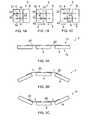
- FIGS. 6A and 6Billustrate one of many possible implementations of an interconnect for the apparatus
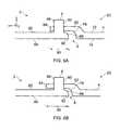
- FIG. 7illustrates a housing apparatus in longitudinal cross-section that comprises multiple portions 102 connected in series via interconnects
- FIG. 8illustrates the housing apparatus from a perspective view
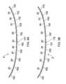
- FIGS. 9A and 9Billustrate the housing apparatus with different configurations of interconnects.
- FIGS. 1A , 1 B and 1 Cillustrate one example of an apparatus 2 that comprises a first portion 4 and a second portion 6 .
- the first portion 4 and the second portion 6are configured for relative movement.
- the movementmay be movement 3 towards each other as illustrated in FIG. 1B or movement 5 away from each other as illustrated in FIG. 1C .
- An interconnect 20interconnects the first portion 4 and the second portion 6 . It is, in this example, configured both to enable reciprocal movement of the first portion 4 and the second portion 6 towards and away from each other and also to limit movement of the first portion 4 and the second portion 6 relative to each other.
- the interconnect 20may comprise a compression transmission arrangement 8 . It is, in this example, configured both to enable movement of the first portion 4 and the second portion 6 towards each other and also to limit movement of the first portion 4 and the second portion 6 towards each other.
- the compression transmission arrangement 8is configured to transmit compression forces between the first portion 4 and the second portion 6 to limit movement of the first portion 4 and the second portion 6 towards each other, such that they do not approach within a minimum value for a separation distance between the first portion 4 and the second portion 6 .
- the interconnect 20may optionally comprise a tension transmission arrangement 10 . It is, in this example, configured both to enable movement of the first portion 4 and the second portion 6 away from each other and also to limit movement of the first portion 4 and the second portion 6 away from each other.
- the tension transmission arrangement 10is configured to transmit tension forces between the first portion 4 and the second portion 6 to limit movement of the first portion 4 and the second portion 6 away from each other, such that they do not separate by more than a maximum value for a separation distance between the first portion 4 and the second portion 6 .
- the compression transmission arrangement 8in this example, is configured to transmit compression forces between the first portion 4 and the second portion 6 and, in this example, comprises a first compression abutment surface 42 .
- a first compression resisting surface 41is, in this example, configured to transmit a force to the first portion 4 . It may, for example be connected or coupled to the first portion 4 . It may, for example, be fixed to the first portion 4 or an integral part of the first portion 4 .
- Relative spacing between the first compression resisting surface 41 and the first compression abutment surface 42in this example, enables movement of the first portion 4 and the second portion 6 towards each other as is illustrated by the sequence of FIG. 1C , FIG. 1A , and FIG. 1B .
- the first portion 4 and the second portion 6move towards each other in this example until abutment of the first compression resisting surface 41 and the first compression abutment surface 42 as illustrated in FIG. 1B . Abutment of the first compression resisting surface 41 and the first compression abutment surface 42 creates a compression force.
- the compression force transmitted through the compression transmission arrangement 8resists further movement of the first portion 4 and the second portion 6 towards each other beyond a minimum separation distance.
- the compression transmission arrangement 8therefore should be capable of transmitting a compressive force. It may therefore comprise a structure that is stiff and strong.
- the tension transmission arrangement 10may be configured to transmit tension forces between the first portion 4 and the second portion 6 . It comprises, in this example, a first tension abutment surface 32 .
- a first tension resisting surface 31is configured, in this example, to transmit a force to the first portion 4 . It may, for example be connected or coupled to first portion 4 . It may, for example, be fixed to the first portion 4 or an integral part of the first portion 4 .
- Relative spacing between the first tension resisting surface 31 and the first tension abutment surface 32in this example, enables movement of the first portion 4 and the second portion 6 away from each other as is illustrated by the sequence of FIG. 1B , FIG. 1A , and FIG. 1C .
- the first portion 4 and the second portion 6move away from each other in this example until abutment of the first tension resisting surface 31 and the first tension abutment surface 32 as illustrated in FIG. 1C . Abutment of the first tension resisting surface 31 and the first tension abutment surface 32 creates a tension force.
- the tension force transmitted through the tension transmission arrangement 10resists further movement of the first portion 4 and the second portion 6 away from each other beyond a maximum separation distance.
- the tension transmission arrangement 10therefore needs to be capable of transmitting a tension force. It may therefore comprise a structure that has good tensile strength.
- interconnects 20interconnects adjacent portions of the apparatus 2 . They are in this example located on the same side 12 of an equilibrium plane of the apparatus 2 .
- the interconnects 20may be configured to limit the bending and/or twisting of the apparatus 2 , for example, by providing a tension transmission arrangement 10
- first side 12is shortened, as illustrated in the example of FIG. 2C , generates compression on the first side of the equilibrium plane.
- the strainingmay arise from bending and/or twisting the apparatus 2 .
- the lengthis measured over the surface of the side 12 . This surface is flat in FIG. 2A and arcuate (concave) in FIG. 2C .
- the interconnects 20may be configured to limit the bending and/or twisting of the apparatus 2 , for example, by providing a compression transmission arrangement 10 .
- a dual-purpose interconnect 20is positioned on one side 12 of the equilibrium plane and provides both a tension transmission arrangement 10 to limit convex bending, for example, and a compression transmission arrangement 8 to limit concave bending, for example.
- a dual-purpose interconnect 20may be positioned on the opposite side of the equilibrium plane to the preceding example and may provide both a tension transmission arrangement 10 to limit concave bending, for example, and a compression transmission arrangement 8 to limit convex bending, for example.
- a single-purpose interconnect 20may be positioned on one side of the equilibrium plane and may provide either one of the tension transmission arrangement 10 and the compression transmission arrangement 8 and another interconnect 20 may be positioned on the other side of the equilibrium plane and provide either one of the tension transmission arrangement 10 and the compression transmission arrangement 8 .
- one or more interconnects 20may be positioned on one side of the equilibrium plane and may provide either (but not both) the tension transmission arrangement 10 or the compression transmission arrangement 8 .
- FIG. 3Aillustrates an example interconnect 20 of the apparatus 2 from a side view.
- FIG. 3Billustrates the example interconnect 20 of the apparatus 2 in longitudinal cross-section.
- FIG. 3Cillustrates the example interconnect 20 of the apparatus 2 in transverse cross-section.
- An x-y-z Cartesian coordinate systemis illustrated, where x, y and z represent mutually orthogonal directions.
- the x-directiondefines a first direction.
- the y-direction and z-directiondefine transverse directions.
- the example interconnect 20 of the apparatus 2comprises a first portion 4 comprising a projection 50 extending in a first direction (x-direction) and a second portion 6 comprising an aperture 60 extending in the first direction.
- the first portion 4 and the second portion 6are both rigid.
- the first portion 4 and the second portion 6are configured for relative reciprocating movement in the first direction.
- the projection 50extends from the first portion 4 in the x-direction between the first portion 4 and the second portion through the aperture 60 .
- sidewalls of the aperture 60surround the projection 50 with clearances 70 .
- the clearances 70are configured to enforce limits on relative movement of the first portion 4 and the second portion 6 while enabling reciprocating movement of the first portion 4 and the second portion 6 in the x-direction towards each other and away from each other.
- FIG. 3Dillustrates in more detail the clearances 70 .
- Transverse clearances d 1 , d 2 , d 3 , d 4 between the projection 50 and the surrounding sidewalls of the aperture 60 in the second portion 6are configured to enforce limits on relative transverse movement of the first portion 4 and the second portion 6 about the interconnect 20 defining those clearances 70 .
- the clearances 70enforce limits on movement of the first portion 4 and the second portion because they define how much the first portion (projection 50 ) can move relative to the second portion (sidewalls of the aperture 60 ) before the projection 50 and the sidewalls of the aperture 60 abut.
- the lateral clearances d 2 , d 3 in the y-direction between the projection 50 and the surrounding sidewalls of the aperture 60are configured to enforce limits on relative lateral movement (y-direction) of the first portion 4 and the second portion 6 .
- the lateral clearances d 2 , d 3also enforce limits on relative movement of the first portion 4 and the second portion 6 about a vertical transverse axis orthogonal to the x-direction and parallel to the z-direction.
- the lateral clearances d 2 , d 3may therefore limit yaw, for example, as illustrated in FIGS. 4A , 4 B, 4 C, by abutment of the projection 50 and the sidewalls of the aperture 60 .
- the vertical clearances d 1 , d 4 in the z-direction between the projection 50 and the surrounding sidewalls of the aperture 60are configured to enforce limits on relative vertical movement (z-direction) of the first portion 4 and the second portion 6 .
- the vertical clearances d 1 , d 4also enforce limits on relative movement of the first portion 4 and the second portion 6 about a horizontal transverse axis orthogonal to the x-direction and parallel to the y-direction.
- the vertical clearances d 1 , d 4may therefore limit pitch, for example, as illustrated in FIGS. 4A , 4 B, 4 C, by abutment of the projection 50 and the aperture 60 .
- the transverse clearances d 1 , d 2 , d 3 , d 4 between the projection 50 and the surrounding aperture 60are configured to enforce limits on relative movement of the first portion 4 and the second portion 6 about a horizontal axis parallel to the x-direction.
- the transverse clearances d 1 , d 2 , d 3 , d 4may therefore limit roll as the projection 50 is not rotatable within the aperture 60 about an axis parallel to the x-direction.
- the projection 50may be considered to be a tenon in a mortice defined by the aperture 60 .
- the aperture 60extends fully through a part of the second portion 6 .
- the relative size and shape of the tenon compared to the morticecontrols the clearances 70 and hence limits relative movement of the first portion 4 and the second portion 6 .
- the tenoncan reciprocate within the mortice enabling reciprocating movement of the first portion 4 and the second portion 6 in the x-direction.
- the tenonmay have a rectangular or square cross-section.
- the morticemay also have a rectangular or square cross-section.
- the aspect ratio (ratio of width to height) of the cross-section of the tenon and the cross-section of the morticemay be the same.
- the tenonIn cross-section in a plane orthogonal to the x-direction, the tenon may have a bar shape in cross-section and the mortice may have a slot shape in cross-section as illustrated in FIG. 3C .
- a length of the projection 50may enforce limits on relative movement of the first portion 4 and the second portion 6 about a horizontal transverse axis orthogonal to the x-direction and parallel to the y-direction.
- the lengthmay therefore limit pitch, for example, as illustrated in FIGS. 5A , 5 B by abutment of a terminal part 94 of the projection 50 and the second portion 6 .
- abutmentmay occur between the projection 50 of the first portion 4 and the second portion 6 when the first portion pitches or yaws relative to the second portion 6 .
- This abutmentmay provide a tension transmission arrangement 10 as previously described.
- FIGS. 6A and 6Billustrate one of many possible implementations of an interconnect 20 for the apparatus 2 .
- the protection 50 of the first portion 4passes through the aperture 60 in the second portion 6 .
- the projection 50is positioned at an interior surface 72 of the first portion 4 and the aperture 60 is positioned at an interior surface 82 of the second portion 6 .
- an exterior surface 74 of the first portion 4 and an exterior surface 84 of the second portion 6are aligned in the x-direction
- the exterior surface 74 of the first portion 4 and the exterior surface 84 of the second portionare aligned with the x-direction.
- a lug 86extends in the z-direction upwards from the interior surface 82 of the second portion 6 .
- the lug 86has a through-hole in the x-direction that defines the aperture 60 .
- the projection 50extends through the aperture 60 in the lug 86 .
- the projection 50can reciprocate in the x-direction within the aperture 60 .
- the exterior surface 74 of the first portion 4 and the projection 50are connected via a surface portion 78 of the first portion 4 .
- the exterior surface 84 of the second portion 6 and the lug 86 defining the aperture 6are connected via a surface portion 88 of the second portion 6 .
- the surface portion 78 of the first portion 4 and the surface portion 88 of the second portion 6are configured to abut to limit movement of the first portion 4 and the second portion 6 towards each other.
- This abutmentprovides a compression transmission arrangement 8 as previously described.
- the surface portion 78 of the first portion 4is concave and the surface portion 88 of the second portion 6 is convex to match the concave surface portion 78 of the first part.
- the first portion 4 and the second portion 6overlap at an area of overlap 90 which increases in size when the first portion 4 and the second portion 6 move towards each other in the x-direction ( FIG. 6B ) and which decreases in size when the first portion 4 and the second portion 6 move away from each other in the x-direction ( FIG. 6A ).
- the projection 50extends through the aperture 60 in the area of overlap.
- the second portion 6comprises an exterior visible edge 92 that permanently overlaps the first portion 4 and defines an extremity of the area of overlap 90 .
- the other extremity of the area of overlapmay be defined by a terminal portion 94 of the projection 50 .
- the interconnect 20 illustrated in FIGS. 6A and 6Bmay be used to provide a housing apparatus 2 as illustrated in FIGS. 7 and 8 .
- FIG. 7illustrates the housing apparatus 2 in longitudinal cross-section.
- FIG. 8illustrates the housing apparatus 2 , from a perspective view.
- the housing apparatus 2may define one or more cavities 100 for receiving electronic components.
- the housing apparatus 2may provide a shield for the electronic components.
- the housing apparatus 2may be formed from only rigid components.
- the housing apparatus 2may be an exterior housing that is used without an additional covering layer.
- the clearances 70 between the projections 50 and apertures 60 of the interconnects 20may be filled with resiliently deformable, waterproof material such as an elastomer, for example, to provide weather-proofing of the housing apparatus 2 .
- multiple portions 102 of the housing apparatus 2are interconnected in series via interconnections 20 . There is an interconnection 20 between adjacent portions of the multiple portions 102 .
- each of the multiple portions 102 and its adjacent portion 102may function as the first portion 4 and the second portion 6 previously described.
- Each interconnection 20comprises a projection 50 extending through an aperture 60 that surrounds the projection 50 with clearances 70 configured to enforce limits on relative movement of the adjacent portions 102 while enabling reciprocating movement of the adjacent portions 102 in the x-direction.
- the portion 102 that terminates the series of interconnected portions on the left of the figurecomprises a projection 50 extending in the x-direction from a rightmost end of that portion 102 . Also, the portion 102 that terminates the series of interconnected portions on the right of the figure, comprises an aperture 60 extending in the x-direction at a leftmost end of that portion 102 .
- Portions 102 that are intermediate in the series of interconnected portionsextend between the terminal portions.
- Each of the intermediate portions 102comprises a projection 50 extending in the x-direction from a rightmost end of the intermediate portion 102 and an aperture extending in the x-direction at the leftmost end of the same intermediate portion 102 .
- Each projection 50 in the series of interconnected portions 102extends in the x-direction through the aperture 60 of an adjacent one of the multiple portions 102 .
- Each aperture 60surrounds that projection 50 with clearances 70 configured to enforce limits on relative movement of the adjacent portions 102 while enabling reciprocating movement of the adjacent portions 102 in the x-direction towards each other and away from each other.
- FIGS. 9A and 9Billustrate in longitudinal cross-section an apparatus 2 that comprises a series of portions 102 that are connected in series via interconnects 20 , similar to the apparatus 2 illustrated in FIGS. 7 and 8 .
- each of the interconnects 20is the same.
- Each interconnect 20has the same vertical clearances 70 between projection 50 and aperture 60 .
- the apparatus 2may be bent with a constant radius of curvature as illustrated in the Figure.
- each of the interconnects 20are not necessarily the same.
- the interconnects 20 towards the end of the series of interconnects 20have greater vertical clearances 70 between projection 50 and aperture 60 than the interconnects 20 at the center of the series of interconnects 20 . Consequently, the apparatus 2 may be bent with a radius of curvature that is greater towards the edges of the apparatus 2 than at the center of the apparatus 2 as illustrated in the Figure.
- the radius of curvaturemay increase symmetrically towards the edges of the apparatus 2 with distance from a transverse center line 110 . This may be achieved by making the vertical clearances 70 for interconnections 20 that are positioned equal distances from a transverse center line 110 the same and increasing the vertical clearances 70 with distance from the center line 110 .
Landscapes
- Engineering & Computer Science (AREA)
- Theoretical Computer Science (AREA)
- Computer Hardware Design (AREA)
- Physics & Mathematics (AREA)
- Human Computer Interaction (AREA)
- General Engineering & Computer Science (AREA)
- General Physics & Mathematics (AREA)
- Power Engineering (AREA)
- Mathematical Physics (AREA)
- Signal Processing (AREA)
- Electric Cable Arrangement Between Relatively Moving Parts (AREA)
Abstract
Description
Claims (5)
Priority Applications (3)
| Application Number | Priority Date | Filing Date | Title |
|---|---|---|---|
| US13/657,203US9158332B2 (en) | 2012-10-22 | 2012-10-22 | Limiting movement |
| PCT/IB2013/055651WO2014064546A1 (en) | 2012-10-22 | 2013-07-10 | Limiting movement |
| EP13848321.9AEP2910004A4 (en) | 2012-10-22 | 2013-07-10 | Limiting movement |
Applications Claiming Priority (1)
| Application Number | Priority Date | Filing Date | Title |
|---|---|---|---|
| US13/657,203US9158332B2 (en) | 2012-10-22 | 2012-10-22 | Limiting movement |
Publications (2)
| Publication Number | Publication Date |
|---|---|
| US20140112704A1 US20140112704A1 (en) | 2014-04-24 |
| US9158332B2true US9158332B2 (en) | 2015-10-13 |
Family
ID=50485462
Family Applications (1)
| Application Number | Title | Priority Date | Filing Date |
|---|---|---|---|
| US13/657,203Expired - Fee RelatedUS9158332B2 (en) | 2012-10-22 | 2012-10-22 | Limiting movement |
Country Status (3)
| Country | Link |
|---|---|
| US (1) | US9158332B2 (en) |
| EP (1) | EP2910004A4 (en) |
| WO (1) | WO2014064546A1 (en) |
Cited By (3)
| Publication number | Priority date | Publication date | Assignee | Title |
|---|---|---|---|---|
| US20160170450A1 (en)* | 2014-12-16 | 2016-06-16 | Samsung Display Co., Ltd. | Rollable display |
| US20180011517A1 (en)* | 2016-07-05 | 2018-01-11 | Samsung Display Co., Ltd. | Rollable display device and electronic device including the same |
| USD828321S1 (en) | 2015-11-04 | 2018-09-11 | Lenovo (Beijing) Co., Ltd. | Flexible smart mobile phone |
Families Citing this family (5)
| Publication number | Priority date | Publication date | Assignee | Title |
|---|---|---|---|---|
| KR102183002B1 (en)* | 2014-09-02 | 2020-11-25 | 삼성전자주식회사 | Display apparatus and control method for the same |
| CN107408362B (en)* | 2015-12-31 | 2020-04-14 | 深圳市柔宇科技有限公司 | Bendable mobile terminal |
| US10501973B2 (en) | 2016-06-14 | 2019-12-10 | Microsoft Technology Licensing, Llc | Hinge with free-stop function |
| US10301858B2 (en)* | 2016-06-14 | 2019-05-28 | Microsoft Technology Licensing, Llc | Hinge mechanism |
| US10061359B2 (en)* | 2016-07-28 | 2018-08-28 | Microsoft Technology Licensing, Llc | Hinged device with living hinge |
Citations (86)
| Publication number | Priority date | Publication date | Assignee | Title |
|---|---|---|---|---|
| US1410366A (en)* | 1921-02-17 | 1922-03-21 | Bippart Griscom & Osborn | Joint for bracelet links |
| US3880500A (en) | 1973-12-28 | 1975-04-29 | American Velcro Inc | Mirrors having stretched reflective sheet materials |
| US4483020A (en)* | 1982-11-17 | 1984-11-20 | Jack P. Cittadine | Projectile proof vest |
| US5007108A (en)* | 1989-08-29 | 1991-04-16 | Sport Maska Inc. | Chest protector |
| US5214623A (en)* | 1992-10-16 | 1993-05-25 | Timex Corporation | Wristwatch radiotelephone |
| US5588167A (en) | 1991-11-13 | 1996-12-31 | Ssi Medical Services, Inc. | Apparatus and method for managing waste from patient care maintenance and treatment |
| US5706026A (en) | 1993-01-25 | 1998-01-06 | Kent; Robert Hormann | Finger operated digital input device |
| US5771489A (en)* | 1996-11-12 | 1998-06-30 | Titan Corporation | Penetration-resistant hinge and flexible armor incorporating same |
| US5795430A (en) | 1993-12-18 | 1998-08-18 | International Business Machines Corporation | Faceplate bonding process for a visual display unit |
| US5923318A (en) | 1996-04-12 | 1999-07-13 | Zhai; Shumin | Finger manipulatable 6 degree-of-freedom input device |
| WO2000060438A2 (en) | 1999-04-02 | 2000-10-12 | Think Outside | Foldable keyboard |
| US6160540A (en) | 1998-01-12 | 2000-12-12 | Xerox Company | Zoomorphic computer user interface |
| US20010033275A1 (en) | 1995-01-24 | 2001-10-25 | Joel Kent | Acoustic touch position sensor using a low acoustic loss transparent substrate |
| US20020033798A1 (en) | 2000-09-20 | 2002-03-21 | Fujitsu Takamisawa Component Limited | Pointing device |
| US20020167495A1 (en) | 2001-05-11 | 2002-11-14 | Brian P. Quinn | Collapsible data entry panel |
| US6556189B1 (en) | 1998-04-24 | 2003-04-29 | Nissha Printing Co., Ltd. | Touch panel device |
| US6557177B2 (en)* | 2000-10-05 | 2003-05-06 | Peter Hochmuth | Glove with a reinforcement strip |
| US20030144034A1 (en) | 2001-12-12 | 2003-07-31 | Hack Michael G. | Intelligent multi-media display communication system |
| US20030147205A1 (en) | 2001-02-11 | 2003-08-07 | Murphy Stephen C. | Expandable keyboard for portable computers |
| US20030210801A1 (en) | 2002-05-07 | 2003-11-13 | Alex Naksen | Adjustable headphone |
| US20030214485A1 (en) | 2002-05-17 | 2003-11-20 | Roberts Jerry B. | Calibration of force based touch panel systems |
| US20030227441A1 (en) | 2002-03-29 | 2003-12-11 | Kabushiki Kaisha Toshiba | Display input device and display input system |
| US20040008191A1 (en) | 2002-06-14 | 2004-01-15 | Ivan Poupyrev | User interface apparatus and portable information apparatus |
| US20040017355A1 (en) | 2002-07-24 | 2004-01-29 | Youngtack Shim | Cursor control systems and methods |
| JP2004046792A (en) | 2002-03-29 | 2004-02-12 | Toshiba Corp | Display input device, display input system, control method therefor, and man-machine interface device |
| US20040035994A1 (en) | 2002-08-24 | 2004-02-26 | Samsung Electronics Co., Ltd | Display apparatus |
| US20040046739A1 (en) | 2002-09-11 | 2004-03-11 | Palm, Inc. | Pliable device navigation method and apparatus |
| JP2004192241A (en) | 2002-12-10 | 2004-07-08 | Sony Corp | User interface device and portable information device |
| US20040239631A1 (en) | 2003-05-30 | 2004-12-02 | Gresham Michael D. | Ergonomic input device |
| US20050051693A1 (en) | 2003-08-07 | 2005-03-10 | Yao-Wen Chu | Flat panel display |
| US20050057527A1 (en) | 2003-09-17 | 2005-03-17 | Sony Corporation | Information display device and supporting frame for supporting a piezoelectric element for use in information display device |
| CN1617614A (en) | 2003-11-10 | 2005-05-18 | 仁宝电脑工业股份有限公司 | Handheld electronic device with multiple display modes |
| US20050140646A1 (en) | 2003-12-11 | 2005-06-30 | Canon Kabushiki Kaisha | Display apparatus |
| US20050162389A1 (en) | 2002-04-12 | 2005-07-28 | Obermeyer Henry K. | Multi-axis joystick and transducer means therefore |
| WO2005093548A1 (en) | 2004-03-29 | 2005-10-06 | Koninklijke Philips Electronics N.V. | Controlling a visual display by bending |
| US20050237308A1 (en) | 2004-04-21 | 2005-10-27 | Nokia Corporation | Graphical functions by gestures |
| US20060007151A1 (en) | 2004-06-08 | 2006-01-12 | Pranil Ram | Computer Apparatus with added functionality |
| US20060077672A1 (en) | 2004-09-30 | 2006-04-13 | Adesso Inc. | Gooseneck lighting apparatus with decorative woven sleeve |
| US7075527B2 (en) | 2002-08-26 | 2006-07-11 | Wacoh Corporation | Input device of rotational operation quantity and operating device using this |
| US20060199999A1 (en) | 2001-06-29 | 2006-09-07 | Intuitive Surgical Inc. | Cardiac tissue ablation instrument with flexible wrist |
| US20060238494A1 (en) | 2005-04-22 | 2006-10-26 | International Business Machines Corporation | Flexible displays as an input device |
| US20070040810A1 (en) | 2005-08-18 | 2007-02-22 | Eastman Kodak Company | Touch controlled display device |
| EP1770965A1 (en) | 2005-09-29 | 2007-04-04 | LG Electronics Inc. | Mobile terminal with a plurality of slidable keypads |
| US20070154254A1 (en)* | 2006-01-03 | 2007-07-05 | Bevirt Joeben | Mounting apparatus using ball and socket joints with gripping features |
| EP1830336A1 (en) | 2005-02-22 | 2007-09-05 | FUJIFILM Corporation | Flexible substrate supprerssed from being plastically deformed, and flexible image display device |
| US20080018631A1 (en)* | 2006-07-24 | 2008-01-24 | Kabushiki Kaisha Toshiba | Display device |
| US20080042940A1 (en)* | 2006-08-21 | 2008-02-21 | Fujifilm Corporation | Display device |
| US20080251662A1 (en) | 2007-04-16 | 2008-10-16 | Anton/Bauer, Inc. | Articulated support assembly |
| KR20090001161A (en) | 2007-06-29 | 2009-01-08 | (주)화백엔지니어링 | Tin-nanodiamond electroless composite plating solution, plating film using the same |
| KR20090006807A (en) | 2007-07-11 | 2009-01-15 | 오의진 | Data input device using finger motion detection and input conversion method using the same |
| US20090058828A1 (en) | 2007-08-20 | 2009-03-05 | Samsung Electronics Co., Ltd | Electronic device and method of operating the same |
| US20090088204A1 (en) | 2007-10-01 | 2009-04-02 | Apple Inc. | Movement-based interfaces for personal media device |
| WO2009050107A2 (en) | 2007-10-10 | 2009-04-23 | Vodafone Holding Gmbh | Flexible electronic device and method for the control thereof |
| US20090115734A1 (en) | 2007-11-02 | 2009-05-07 | Sony Ericsson Mobile Communications Ab | Perceivable feedback |
| US20090184921A1 (en) | 2008-01-18 | 2009-07-23 | Microsoft Corporation | Input Through Sensing of User-Applied Forces |
| US20090219247A1 (en) | 2008-02-29 | 2009-09-03 | Hitachi, Ltd. | Flexible information display terminal and interface for information display |
| US20090237872A1 (en) | 2006-06-22 | 2009-09-24 | Polymer Vision Limited | Auto-closable flexible display device |
| US20090244013A1 (en) | 2008-03-27 | 2009-10-01 | Research In Motion Limited | Electronic device and tactile touch screen display |
| US20090326833A1 (en) | 2008-06-30 | 2009-12-31 | Tapani Ryhanen | Apparatus |
| US20100011291A1 (en) | 2008-07-10 | 2010-01-14 | Nokia Corporation | User interface, device and method for a physically flexible device |
| US20100013939A1 (en) | 2007-01-05 | 2010-01-21 | Takehide Ohno | Image apparatus and electronic device |
| WO2010041227A1 (en) | 2008-10-12 | 2010-04-15 | Barit, Efrat | Flexible devices and related methods of use |
| US20100108828A1 (en) | 2008-11-06 | 2010-05-06 | Hong Fu Jin Precision Industry (Shenzhen) Co., Ltd. | Supporting structure and flat panel display assembly using same |
| US20100141605A1 (en) | 2008-12-08 | 2010-06-10 | Samsung Electronics Co., Ltd. | Flexible display device and data displaying method thereof |
| US20100164888A1 (en) | 2008-12-26 | 2010-07-01 | Sony Corporation | Display device |
| US20100228295A1 (en) | 2009-03-09 | 2010-09-09 | Whitefield Plastics | Variable Radius Vertebra Bend Restrictor |
| US20100238612A1 (en) | 2009-03-18 | 2010-09-23 | Po-Wen Hsiao | Flexible Display Device |
| US20100263245A1 (en) | 2009-04-17 | 2010-10-21 | Michael John Bowser | Retractable Display Board |
| US20110062703A1 (en) | 2009-07-29 | 2011-03-17 | Icu Medical, Inc. | Fluid transfer devices and methods of use |
| US20110080155A1 (en) | 2009-10-02 | 2011-04-07 | Research In Motion Limited | Method of switching power modes and a portable electronic device configured to perform the same |
| EP2315186A2 (en) | 2009-10-26 | 2011-04-27 | Lg Electronics Inc. | Mobile terminal with flexible body for inputting a signal upon bending said body |
| US20110095999A1 (en) | 2009-10-23 | 2011-04-28 | Plastic Logic Limited | Electronic document reading devices |
| US20110167391A1 (en) | 2010-01-06 | 2011-07-07 | Brian Momeyer | User interface methods and systems for providing force-sensitive input |
| US20110181494A1 (en) | 2010-01-25 | 2011-07-28 | Gt Biomescilt Light Limited | Flexible LED Display Screens |
| US20110193771A1 (en) | 2010-02-10 | 2011-08-11 | Sony Ericsson Mobile Communications Ab | Electronic device controllable by physical deformation |
| WO2011117681A1 (en) | 2010-03-25 | 2011-09-29 | Nokia Corporation | Contortion of an electronic apparatus |
| US20110241822A1 (en) | 2008-12-15 | 2011-10-06 | Koninklijke Philips Electronics N.V. | User interface device and method |
| WO2011144972A1 (en) | 2010-05-21 | 2011-11-24 | Nokia Corporation | A method, an apparatus and a computer program for controlling an output from a display of an apparatus |
| US8194399B2 (en) | 2010-07-16 | 2012-06-05 | Hewlett-Packard Development Company, L.P. | Altering the flexibility of a display device |
| US20120206375A1 (en) | 2011-02-14 | 2012-08-16 | Research In Motion Limited | Portable electronic device including touch-sensitive display and method of controlling same |
| EP2508960A2 (en) | 2011-04-06 | 2012-10-10 | Research In Motion Limited | Gesture recognition on a portable device with force-sensitive housing |
| US8380327B2 (en) | 2010-01-29 | 2013-02-19 | Pantech Co., Ltd. | Flexible electronic product having a shape change characteristic and method thereof |
| WO2013160737A1 (en) | 2012-04-27 | 2013-10-31 | Nokia Corporation | Apparatus and method for allowing relative movement between apparatus portions and at the same time limiting said movement |
| US20130335929A1 (en)* | 2012-06-19 | 2013-12-19 | Motorola Mobility, Inc. | Electronic device and method with flexible display |
| US20140003006A1 (en)* | 2012-06-28 | 2014-01-02 | Sung-Sang Ahn | Flexible display device |
| US8780540B2 (en) | 2012-03-02 | 2014-07-15 | Microsoft Corporation | Flexible hinge and removable attachment |
Family Cites Families (1)
| Publication number | Priority date | Publication date | Assignee | Title |
|---|---|---|---|---|
| US7104715B2 (en)* | 2003-08-22 | 2006-09-12 | Rast Associates, Llc | Deployable keyboard device including displaceable keybutton positions for portable miniature electronic devices |
- 2012
- 2012-10-22USUS13/657,203patent/US9158332B2/ennot_activeExpired - Fee Related
- 2013
- 2013-07-10WOPCT/IB2013/055651patent/WO2014064546A1/enactiveApplication Filing
- 2013-07-10EPEP13848321.9Apatent/EP2910004A4/ennot_activeWithdrawn
Patent Citations (99)
| Publication number | Priority date | Publication date | Assignee | Title |
|---|---|---|---|---|
| US1410366A (en)* | 1921-02-17 | 1922-03-21 | Bippart Griscom & Osborn | Joint for bracelet links |
| US3880500A (en) | 1973-12-28 | 1975-04-29 | American Velcro Inc | Mirrors having stretched reflective sheet materials |
| US4483020A (en)* | 1982-11-17 | 1984-11-20 | Jack P. Cittadine | Projectile proof vest |
| US5007108A (en)* | 1989-08-29 | 1991-04-16 | Sport Maska Inc. | Chest protector |
| US5588167A (en) | 1991-11-13 | 1996-12-31 | Ssi Medical Services, Inc. | Apparatus and method for managing waste from patient care maintenance and treatment |
| US5214623A (en)* | 1992-10-16 | 1993-05-25 | Timex Corporation | Wristwatch radiotelephone |
| US5706026A (en) | 1993-01-25 | 1998-01-06 | Kent; Robert Hormann | Finger operated digital input device |
| US5795430A (en) | 1993-12-18 | 1998-08-18 | International Business Machines Corporation | Faceplate bonding process for a visual display unit |
| US6441809B2 (en) | 1995-01-24 | 2002-08-27 | Elo Touchsystems, Inc. | Acoustic touch position sensor using a low acoustic loss transparent substrate |
| US20010033275A1 (en) | 1995-01-24 | 2001-10-25 | Joel Kent | Acoustic touch position sensor using a low acoustic loss transparent substrate |
| US5923318A (en) | 1996-04-12 | 1999-07-13 | Zhai; Shumin | Finger manipulatable 6 degree-of-freedom input device |
| US5771489A (en)* | 1996-11-12 | 1998-06-30 | Titan Corporation | Penetration-resistant hinge and flexible armor incorporating same |
| US6160540A (en) | 1998-01-12 | 2000-12-12 | Xerox Company | Zoomorphic computer user interface |
| US6556189B1 (en) | 1998-04-24 | 2003-04-29 | Nissha Printing Co., Ltd. | Touch panel device |
| WO2000060438A2 (en) | 1999-04-02 | 2000-10-12 | Think Outside | Foldable keyboard |
| US20020033798A1 (en) | 2000-09-20 | 2002-03-21 | Fujitsu Takamisawa Component Limited | Pointing device |
| US6557177B2 (en)* | 2000-10-05 | 2003-05-06 | Peter Hochmuth | Glove with a reinforcement strip |
| US20030147205A1 (en) | 2001-02-11 | 2003-08-07 | Murphy Stephen C. | Expandable keyboard for portable computers |
| US20020167495A1 (en) | 2001-05-11 | 2002-11-14 | Brian P. Quinn | Collapsible data entry panel |
| US20060199999A1 (en) | 2001-06-29 | 2006-09-07 | Intuitive Surgical Inc. | Cardiac tissue ablation instrument with flexible wrist |
| US20030144034A1 (en) | 2001-12-12 | 2003-07-31 | Hack Michael G. | Intelligent multi-media display communication system |
| US20030227441A1 (en) | 2002-03-29 | 2003-12-11 | Kabushiki Kaisha Toshiba | Display input device and display input system |
| JP2004046792A (en) | 2002-03-29 | 2004-02-12 | Toshiba Corp | Display input device, display input system, control method therefor, and man-machine interface device |
| US20050162389A1 (en) | 2002-04-12 | 2005-07-28 | Obermeyer Henry K. | Multi-axis joystick and transducer means therefore |
| US20030210801A1 (en) | 2002-05-07 | 2003-11-13 | Alex Naksen | Adjustable headphone |
| US20030214485A1 (en) | 2002-05-17 | 2003-11-20 | Roberts Jerry B. | Calibration of force based touch panel systems |
| TW200404248A (en) | 2002-05-17 | 2004-03-16 | 3M Innovative Properties Co | Calibration of force based touch panel systems |
| US20040008191A1 (en) | 2002-06-14 | 2004-01-15 | Ivan Poupyrev | User interface apparatus and portable information apparatus |
| US7456823B2 (en) | 2002-06-14 | 2008-11-25 | Sony Corporation | User interface apparatus and portable information apparatus |
| US20040017355A1 (en) | 2002-07-24 | 2004-01-29 | Youngtack Shim | Cursor control systems and methods |
| US20040035994A1 (en) | 2002-08-24 | 2004-02-26 | Samsung Electronics Co., Ltd | Display apparatus |
| US7075527B2 (en) | 2002-08-26 | 2006-07-11 | Wacoh Corporation | Input device of rotational operation quantity and operating device using this |
| US20040046739A1 (en) | 2002-09-11 | 2004-03-11 | Palm, Inc. | Pliable device navigation method and apparatus |
| JP2004192241A (en) | 2002-12-10 | 2004-07-08 | Sony Corp | User interface device and portable information device |
| US20040239631A1 (en) | 2003-05-30 | 2004-12-02 | Gresham Michael D. | Ergonomic input device |
| US20050051693A1 (en) | 2003-08-07 | 2005-03-10 | Yao-Wen Chu | Flat panel display |
| US20050057527A1 (en) | 2003-09-17 | 2005-03-17 | Sony Corporation | Information display device and supporting frame for supporting a piezoelectric element for use in information display device |
| CN1598870A (en) | 2003-09-17 | 2005-03-23 | 索尼株式会社 | Information display device and supporting frame for supporting a piezoelectric element |
| CN1617614A (en) | 2003-11-10 | 2005-05-18 | 仁宝电脑工业股份有限公司 | Handheld electronic device with multiple display modes |
| US20050140646A1 (en) | 2003-12-11 | 2005-06-30 | Canon Kabushiki Kaisha | Display apparatus |
| US7443380B2 (en) | 2003-12-11 | 2008-10-28 | Canon Kabushiki Kaisha | Display apparatus |
| WO2005093548A1 (en) | 2004-03-29 | 2005-10-06 | Koninklijke Philips Electronics N.V. | Controlling a visual display by bending |
| KR20060134130A (en) | 2004-03-29 | 2006-12-27 | 코닌클리케 필립스 일렉트로닉스 엔.브이. | Visual display control by bending |
| US20070205997A1 (en) | 2004-03-29 | 2007-09-06 | Koninklijke Philips Electronics N.V. | Controlling A Visual Display By Bending |
| US20050237308A1 (en) | 2004-04-21 | 2005-10-27 | Nokia Corporation | Graphical functions by gestures |
| US20060007151A1 (en) | 2004-06-08 | 2006-01-12 | Pranil Ram | Computer Apparatus with added functionality |
| US20060077672A1 (en) | 2004-09-30 | 2006-04-13 | Adesso Inc. | Gooseneck lighting apparatus with decorative woven sleeve |
| EP1830336A1 (en) | 2005-02-22 | 2007-09-05 | FUJIFILM Corporation | Flexible substrate supprerssed from being plastically deformed, and flexible image display device |
| US20060238494A1 (en) | 2005-04-22 | 2006-10-26 | International Business Machines Corporation | Flexible displays as an input device |
| US20070040810A1 (en) | 2005-08-18 | 2007-02-22 | Eastman Kodak Company | Touch controlled display device |
| EP1770965A1 (en) | 2005-09-29 | 2007-04-04 | LG Electronics Inc. | Mobile terminal with a plurality of slidable keypads |
| US20070154254A1 (en)* | 2006-01-03 | 2007-07-05 | Bevirt Joeben | Mounting apparatus using ball and socket joints with gripping features |
| US20090237872A1 (en) | 2006-06-22 | 2009-09-24 | Polymer Vision Limited | Auto-closable flexible display device |
| US20080018631A1 (en)* | 2006-07-24 | 2008-01-24 | Kabushiki Kaisha Toshiba | Display device |
| US20080042940A1 (en)* | 2006-08-21 | 2008-02-21 | Fujifilm Corporation | Display device |
| US20100013939A1 (en) | 2007-01-05 | 2010-01-21 | Takehide Ohno | Image apparatus and electronic device |
| US20080251662A1 (en) | 2007-04-16 | 2008-10-16 | Anton/Bauer, Inc. | Articulated support assembly |
| KR20090001161A (en) | 2007-06-29 | 2009-01-08 | (주)화백엔지니어링 | Tin-nanodiamond electroless composite plating solution, plating film using the same |
| KR20090006807A (en) | 2007-07-11 | 2009-01-15 | 오의진 | Data input device using finger motion detection and input conversion method using the same |
| US20090058828A1 (en) | 2007-08-20 | 2009-03-05 | Samsung Electronics Co., Ltd | Electronic device and method of operating the same |
| CN101430601A (en) | 2007-10-01 | 2009-05-13 | 苹果公司 | Mobile-based interface for personal media device |
| US20090088204A1 (en) | 2007-10-01 | 2009-04-02 | Apple Inc. | Movement-based interfaces for personal media device |
| WO2009050107A2 (en) | 2007-10-10 | 2009-04-23 | Vodafone Holding Gmbh | Flexible electronic device and method for the control thereof |
| US20110057873A1 (en) | 2007-10-10 | 2011-03-10 | Jan Geissler | Flexible electronic device and method for the control thereoff |
| US20090115734A1 (en) | 2007-11-02 | 2009-05-07 | Sony Ericsson Mobile Communications Ab | Perceivable feedback |
| US20090184921A1 (en) | 2008-01-18 | 2009-07-23 | Microsoft Corporation | Input Through Sensing of User-Applied Forces |
| US20090219247A1 (en) | 2008-02-29 | 2009-09-03 | Hitachi, Ltd. | Flexible information display terminal and interface for information display |
| US20090244013A1 (en) | 2008-03-27 | 2009-10-01 | Research In Motion Limited | Electronic device and tactile touch screen display |
| US20090326833A1 (en) | 2008-06-30 | 2009-12-31 | Tapani Ryhanen | Apparatus |
| US20100011291A1 (en) | 2008-07-10 | 2010-01-14 | Nokia Corporation | User interface, device and method for a physically flexible device |
| WO2010041227A1 (en) | 2008-10-12 | 2010-04-15 | Barit, Efrat | Flexible devices and related methods of use |
| US20110227822A1 (en)* | 2008-10-12 | 2011-09-22 | Efrat BARIT | Flexible devices and related methods of use |
| US20100108828A1 (en) | 2008-11-06 | 2010-05-06 | Hong Fu Jin Precision Industry (Shenzhen) Co., Ltd. | Supporting structure and flat panel display assembly using same |
| US20100141605A1 (en) | 2008-12-08 | 2010-06-10 | Samsung Electronics Co., Ltd. | Flexible display device and data displaying method thereof |
| US20110241822A1 (en) | 2008-12-15 | 2011-10-06 | Koninklijke Philips Electronics N.V. | User interface device and method |
| US20100164888A1 (en) | 2008-12-26 | 2010-07-01 | Sony Corporation | Display device |
| US20100228295A1 (en) | 2009-03-09 | 2010-09-09 | Whitefield Plastics | Variable Radius Vertebra Bend Restrictor |
| US20100238612A1 (en) | 2009-03-18 | 2010-09-23 | Po-Wen Hsiao | Flexible Display Device |
| US20100263245A1 (en) | 2009-04-17 | 2010-10-21 | Michael John Bowser | Retractable Display Board |
| US20110062703A1 (en) | 2009-07-29 | 2011-03-17 | Icu Medical, Inc. | Fluid transfer devices and methods of use |
| US20110080155A1 (en) | 2009-10-02 | 2011-04-07 | Research In Motion Limited | Method of switching power modes and a portable electronic device configured to perform the same |
| US20110095999A1 (en) | 2009-10-23 | 2011-04-28 | Plastic Logic Limited | Electronic document reading devices |
| US8619021B2 (en) | 2009-10-23 | 2013-12-31 | Plastic Logic Limited | Electronic document reading devices |
| EP2315186A2 (en) | 2009-10-26 | 2011-04-27 | Lg Electronics Inc. | Mobile terminal with flexible body for inputting a signal upon bending said body |
| US20110167391A1 (en) | 2010-01-06 | 2011-07-07 | Brian Momeyer | User interface methods and systems for providing force-sensitive input |
| US20110181494A1 (en) | 2010-01-25 | 2011-07-28 | Gt Biomescilt Light Limited | Flexible LED Display Screens |
| US8380327B2 (en) | 2010-01-29 | 2013-02-19 | Pantech Co., Ltd. | Flexible electronic product having a shape change characteristic and method thereof |
| US20110193771A1 (en) | 2010-02-10 | 2011-08-11 | Sony Ericsson Mobile Communications Ab | Electronic device controllable by physical deformation |
| WO2011117681A1 (en) | 2010-03-25 | 2011-09-29 | Nokia Corporation | Contortion of an electronic apparatus |
| WO2011144972A1 (en) | 2010-05-21 | 2011-11-24 | Nokia Corporation | A method, an apparatus and a computer program for controlling an output from a display of an apparatus |
| US8194399B2 (en) | 2010-07-16 | 2012-06-05 | Hewlett-Packard Development Company, L.P. | Altering the flexibility of a display device |
| US20120206375A1 (en) | 2011-02-14 | 2012-08-16 | Research In Motion Limited | Portable electronic device including touch-sensitive display and method of controlling same |
| EP2508960A2 (en) | 2011-04-06 | 2012-10-10 | Research In Motion Limited | Gesture recognition on a portable device with force-sensitive housing |
| US8780540B2 (en) | 2012-03-02 | 2014-07-15 | Microsoft Corporation | Flexible hinge and removable attachment |
| US8780541B2 (en) | 2012-03-02 | 2014-07-15 | Microsoft Corporation | Flexible hinge and removable attachment |
| WO2013160737A1 (en) | 2012-04-27 | 2013-10-31 | Nokia Corporation | Apparatus and method for allowing relative movement between apparatus portions and at the same time limiting said movement |
| US20130286553A1 (en)* | 2012-04-27 | 2013-10-31 | Nokia Corporation | Limiting movement |
| US20130335929A1 (en)* | 2012-06-19 | 2013-12-19 | Motorola Mobility, Inc. | Electronic device and method with flexible display |
| US20140003006A1 (en)* | 2012-06-28 | 2014-01-02 | Sung-Sang Ahn | Flexible display device |
Non-Patent Citations (6)
| Title |
|---|
| "Gummi: A bendable computer", Dr Ivan Poupyrev-http://ivanpoupyrev.com/projects/gummi.php, (1994-2012), (7 pages). |
| "How Users Manipulate Deformable Displays as Input Devices", Sang-Su Lee et al Apr. 10-15, 2010, (pp. 1647-1656). |
| "Murata Tactile controller TV remote hands-on (video)", Zach Honig-http://www.engadget.com2011/10/05/murata-tactile-controller-tv-remote-ands-on-vi . . . , (2012), (8 pages). |
| "Press release: revolutionary new paper computer shows flexible future for smartphones and tablets", http://www.hml.queensu.ca/paperphone, (2012), (2 pages). |
| Mina; Samsung Unveils Flexible Android Smartphone; http://www.androidauthority.com/samsung-unveils-flexible-android-smartphone-24933/ (8 pages). |
| Smith, Matt; Nokia's kinetic future: flexible screens and a twisted interface; Oct. 26, 2012; http://www.engadget.com/2011/10/26/nokias-kinetic-future-flexible-screens-and-a-twisted-interface/ (4 pages). |
Cited By (6)
| Publication number | Priority date | Publication date | Assignee | Title |
|---|---|---|---|---|
| US20160170450A1 (en)* | 2014-12-16 | 2016-06-16 | Samsung Display Co., Ltd. | Rollable display |
| US9519313B2 (en)* | 2014-12-16 | 2016-12-13 | Samsung Display Co., Ltd. | Rollable display |
| USD828321S1 (en) | 2015-11-04 | 2018-09-11 | Lenovo (Beijing) Co., Ltd. | Flexible smart mobile phone |
| USD859349S1 (en) | 2015-11-04 | 2019-09-10 | Lenovo (Beijing) Co., Ltd. | Flexible electronic device |
| US20180011517A1 (en)* | 2016-07-05 | 2018-01-11 | Samsung Display Co., Ltd. | Rollable display device and electronic device including the same |
| US10095273B2 (en)* | 2016-07-05 | 2018-10-09 | Samsung Display Co., Ltd. | Rollable display device and electronic device including the same |
Also Published As
| Publication number | Publication date |
|---|---|
| US20140112704A1 (en) | 2014-04-24 |
| EP2910004A1 (en) | 2015-08-26 |
| WO2014064546A1 (en) | 2014-05-01 |
| EP2910004A4 (en) | 2016-07-06 |
Similar Documents
| Publication | Publication Date | Title |
|---|---|---|
| US9158332B2 (en) | Limiting movement | |
| US9823696B2 (en) | Limiting movement | |
| CN203813033U (en) | A multi-frequency array antenna | |
| DE102007056258B4 (en) | Chip antenna and associated printed circuit board for a mobile telecommunication device | |
| US10101549B2 (en) | Optical fiber cable | |
| US8821174B2 (en) | Floating connector small in size and improved in strength | |
| US9136623B2 (en) | Connector | |
| DE102013100731A1 (en) | Communication device and antennas with high isolation properties | |
| US20120225585A1 (en) | Electrical connector with equal width connection part | |
| US9252541B2 (en) | Connector | |
| DE102014220107A1 (en) | ANTENNA SYSTEM AND ANTENNA UNIT | |
| CN105519249A (en) | Electrically conductive film, touch panel and display device employing same, and evaluation method for electrically conductive film | |
| US20110173946A1 (en) | Cable or the like protecting and guiding device | |
| US20160064867A1 (en) | Vehicular Cable Assembly | |
| US20150162731A1 (en) | Electric-wire protection pipe and wire harness | |
| DE102010004470A1 (en) | Antenna structure for a vehicle | |
| CN105119051A (en) | Communication device | |
| US20130206443A1 (en) | Metal core substrate and electrical junction box using the same | |
| CN105449353B (en) | All-around top absorbing antenna | |
| CN104078763A (en) | Mimo antenna and electronic equipment | |
| DE102007002466B4 (en) | Connector socket of the industrial information network technology with at least two contact points | |
| DE06025233T1 (en) | Compact multiband antenna | |
| CN210926345U (en) | Antenna reflection plate and antenna | |
| JP5840942B2 (en) | Folded dipole antenna | |
| JP4920008B2 (en) | Electronic device and wiring method of micro coaxial cable assembly in electronic device |
Legal Events
| Date | Code | Title | Description |
|---|---|---|---|
| FEPP | Fee payment procedure | Free format text:PAYOR NUMBER ASSIGNED (ORIGINAL EVENT CODE: ASPN); ENTITY STATUS OF PATENT OWNER: LARGE ENTITY | |
| AS | Assignment | Owner name:NOKIA TECHNOLOGIES OY, FINLAND Free format text:ASSIGNMENT OF ASSIGNORS INTEREST;ASSIGNOR:NOKIA CORPORATION;REEL/FRAME:034781/0200 Effective date:20150116 | |
| AS | Assignment | Owner name:NOKIA CORPORATION, FINLAND Free format text:ASSIGNMENT OF ASSIGNORS INTEREST;ASSIGNORS:VANSKA, ANSSI ILMARI;KOSONEN, MATTI;SALO, ANTTI OSKARI;AND OTHERS;REEL/FRAME:036196/0308 Effective date:20121029 | |
| STCF | Information on status: patent grant | Free format text:PATENTED CASE | |
| AS | Assignment | Owner name:PROVENANCE ASSET GROUP LLC, CONNECTICUT Free format text:ASSIGNMENT OF ASSIGNORS INTEREST;ASSIGNORS:NOKIA TECHNOLOGIES OY;NOKIA SOLUTIONS AND NETWORKS BV;ALCATEL LUCENT SAS;REEL/FRAME:043877/0001 Effective date:20170912 Owner name:NOKIA USA INC., CALIFORNIA Free format text:SECURITY INTEREST;ASSIGNORS:PROVENANCE ASSET GROUP HOLDINGS, LLC;PROVENANCE ASSET GROUP LLC;REEL/FRAME:043879/0001 Effective date:20170913 Owner name:CORTLAND CAPITAL MARKET SERVICES, LLC, ILLINOIS Free format text:SECURITY INTEREST;ASSIGNORS:PROVENANCE ASSET GROUP HOLDINGS, LLC;PROVENANCE ASSET GROUP, LLC;REEL/FRAME:043967/0001 Effective date:20170913 | |
| AS | Assignment | Owner name:NOKIA US HOLDINGS INC., NEW JERSEY Free format text:ASSIGNMENT AND ASSUMPTION AGREEMENT;ASSIGNOR:NOKIA USA INC.;REEL/FRAME:048370/0682 Effective date:20181220 | |
| FEPP | Fee payment procedure | Free format text:MAINTENANCE FEE REMINDER MAILED (ORIGINAL EVENT CODE: REM.); ENTITY STATUS OF PATENT OWNER: LARGE ENTITY | |
| FEPP | Fee payment procedure | Free format text:SURCHARGE FOR LATE PAYMENT, LARGE ENTITY (ORIGINAL EVENT CODE: M1554); ENTITY STATUS OF PATENT OWNER: LARGE ENTITY | |
| MAFP | Maintenance fee payment | Free format text:PAYMENT OF MAINTENANCE FEE, 4TH YEAR, LARGE ENTITY (ORIGINAL EVENT CODE: M1551); ENTITY STATUS OF PATENT OWNER: LARGE ENTITY Year of fee payment:4 | |
| AS | Assignment | Owner name:PROVENANCE ASSET GROUP LLC, CONNECTICUT Free format text:RELEASE BY SECURED PARTY;ASSIGNOR:CORTLAND CAPITAL MARKETS SERVICES LLC;REEL/FRAME:058983/0104 Effective date:20211101 Owner name:PROVENANCE ASSET GROUP HOLDINGS LLC, CONNECTICUT Free format text:RELEASE BY SECURED PARTY;ASSIGNOR:CORTLAND CAPITAL MARKETS SERVICES LLC;REEL/FRAME:058983/0104 Effective date:20211101 Owner name:PROVENANCE ASSET GROUP LLC, CONNECTICUT Free format text:RELEASE BY SECURED PARTY;ASSIGNOR:NOKIA US HOLDINGS INC.;REEL/FRAME:058363/0723 Effective date:20211129 Owner name:PROVENANCE ASSET GROUP HOLDINGS LLC, CONNECTICUT Free format text:RELEASE BY SECURED PARTY;ASSIGNOR:NOKIA US HOLDINGS INC.;REEL/FRAME:058363/0723 Effective date:20211129 | |
| AS | Assignment | Owner name:RPX CORPORATION, CALIFORNIA Free format text:ASSIGNMENT OF ASSIGNORS INTEREST;ASSIGNOR:PROVENANCE ASSET GROUP LLC;REEL/FRAME:059352/0001 Effective date:20211129 | |
| AS | Assignment | Owner name:BARINGS FINANCE LLC, AS COLLATERAL AGENT, NORTH CAROLINA Free format text:PATENT SECURITY AGREEMENT;ASSIGNOR:RPX CORPORATION;REEL/FRAME:063429/0001 Effective date:20220107 | |
| FEPP | Fee payment procedure | Free format text:MAINTENANCE FEE REMINDER MAILED (ORIGINAL EVENT CODE: REM.); ENTITY STATUS OF PATENT OWNER: LARGE ENTITY | |
| LAPS | Lapse for failure to pay maintenance fees | Free format text:PATENT EXPIRED FOR FAILURE TO PAY MAINTENANCE FEES (ORIGINAL EVENT CODE: EXP.); ENTITY STATUS OF PATENT OWNER: LARGE ENTITY | |
| STCH | Information on status: patent discontinuation | Free format text:PATENT EXPIRED DUE TO NONPAYMENT OF MAINTENANCE FEES UNDER 37 CFR 1.362 | |
| FP | Lapsed due to failure to pay maintenance fee | Effective date:20231013 |