US9157817B1 - HSA swage metrology calibration using solid weight gauge and torque sensor - Google Patents
HSA swage metrology calibration using solid weight gauge and torque sensorDownload PDFInfo
- Publication number
- US9157817B1 US9157817B1US14/299,714US201414299714AUS9157817B1US 9157817 B1US9157817 B1US 9157817B1US 201414299714 AUS201414299714 AUS 201414299714AUS 9157817 B1US9157817 B1US 9157817B1
- Authority
- US
- United States
- Prior art keywords
- assembly
- hsa
- torque
- swaging
- actuator motor
- Prior art date
- Legal status (The legal status is an assumption and is not a legal conclusion. Google has not performed a legal analysis and makes no representation as to the accuracy of the status listed.)
- Expired - Fee Related
Links
Images


Classifications
- G—PHYSICS
- G01—MEASURING; TESTING
- G01L—MEASURING FORCE, STRESS, TORQUE, WORK, MECHANICAL POWER, MECHANICAL EFFICIENCY, OR FLUID PRESSURE
- G01L3/00—Measuring torque, work, mechanical power, or mechanical efficiency, in general
- G01L3/02—Rotary-transmission dynamometers
- G01L3/04—Rotary-transmission dynamometers wherein the torque-transmitting element comprises a torsionally-flexible shaft
- G—PHYSICS
- G11—INFORMATION STORAGE
- G11B—INFORMATION STORAGE BASED ON RELATIVE MOVEMENT BETWEEN RECORD CARRIER AND TRANSDUCER
- G11B5/00—Recording by magnetisation or demagnetisation of a record carrier; Reproducing by magnetic means; Record carriers therefor
- G11B5/455—Arrangements for functional testing of heads; Measuring arrangements for heads
- G—PHYSICS
- G11—INFORMATION STORAGE
- G11B—INFORMATION STORAGE BASED ON RELATIVE MOVEMENT BETWEEN RECORD CARRIER AND TRANSDUCER
- G11B5/00—Recording by magnetisation or demagnetisation of a record carrier; Reproducing by magnetic means; Record carriers therefor
- G11B5/48—Disposition or mounting of heads or head supports relative to record carriers ; arrangements of heads, e.g. for scanning the record carrier to increase the relative speed
- G11B5/4806—Disposition or mounting of heads or head supports relative to record carriers ; arrangements of heads, e.g. for scanning the record carrier to increase the relative speed specially adapted for disk drive assemblies, e.g. assembly prior to operation, hard or flexible disk drives
- G11B5/4813—Mounting or aligning of arm assemblies, e.g. actuator arm supported by bearings, multiple arm assemblies, arm stacks or multiple heads on single arm
- G—PHYSICS
- G11—INFORMATION STORAGE
- G11B—INFORMATION STORAGE BASED ON RELATIVE MOVEMENT BETWEEN RECORD CARRIER AND TRANSDUCER
- G11B5/00—Recording by magnetisation or demagnetisation of a record carrier; Reproducing by magnetic means; Record carriers therefor
- G11B5/40—Protective measures on heads, e.g. against excessive temperature
Definitions
- Embodiments related to the manufacture of rotating media data storage devicesIn particular, embodiments related to the manufacture and testing of components of magnetic hard disk drives.
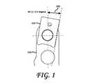
- FIG. 1shows aspects of a conventional head gimbal assembly (HGA) torque out test algorithm.
- HGAhead gimbal assembly
- FIG. 2Ashows an assembly according to one embodiment.
- FIG. 2Bshows another view of an assembly according to one embodiment.
- FIG. 3Ashows further aspects of one embodiment.
- FIG. 3Bshows further aspects of one embodiment.
- FIG. 4shows one exemplary implementation of a reference torque assembly, according to one embodiment.
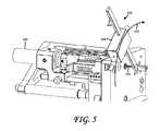
- FIG. 5is a perspective view of the calibration of a swage torque tester using a dummy actuator pivot flex assembly (APFA), according to one embodiment.
- APFAdummy actuator pivot flex assembly
- FIG. 6is a flow chart of a method of calibrating a swage torque tester using a selected reference torque assembly, according to one embodiment.
- Hard disk drivesare critical data storage devices in modern computers. Structurally, a slider comprising read and write transducers is attached to the end of an HGA which is attached to an actuator arm to form a head stack assembly (HSA) through a ball swaging process.
- HSAhead stack assembly
- This processuses a stainless steel ball having a diameter that is wider than a corresponding boss and hole in a base plate of the HGA. As the ball is forced through the hole, the base plate expands and deforms. This deformation mechanically attaches the HGA to the actuator arm with a predetermined amount of contact pressure and retention torque.
- One method of determining swaged torque retention valuesis to test for rotational torque, as shown in FIG. 1 .
- a torque meteris attached to the swage mount of the HGA base plate 102 and rotated until the swage mount is displaced, rotating the swage mount with respect to the actuator arm 104 .
- the amount of ensuing displacementis related to the amount of contact pressure and retention torque. That is, a predetermined amount (e.g., angle 106 ) of rotation is observed for a given amount of torque imparted upon the swage mount. As long as the angle 106 is within acceptable limits, the swaging process is considered to have been carried out within acceptable tolerances.
- the swage torque testeritself requires calibration to ensure that the swaging process is being carried out with the proper amount of contact pressure and retention torque.
- a hand torque gaugeis used as a master to calibrate the swage torque tester.
- this method of swage torque metrology calibration using a hand torque gaugeis not an accurate way to measure the performance of the swage torque tester. This is because, it has been observed, hand torque gauges are susceptible to significant variations in its torque measurement output (typically, about 6%), resulting in uncertainty of the readings.
- the ongoing monitoring of the tester's stabilityis carried out using sample HSA parts. This is problematic because sample parts are not actual parts and the value of the actuator arm—HGA retention force on an actual part is unknown.
- swage torque testers calibrated with a hand torque gaugecannot accurately and consistently represent or predict the performance of the swage torque tester on actual products. Indeed, due to the torque contributions of different parts of the swage torque tester and the variability of the hand torque gauge's output readings, there is an unacceptable uncertainty when attempting to determine whether the HGAs are adequately swaged onto the actuator arms so as to exhibit the desired swage torque retention characteristics.
- GRRGauge Repeatability & Reproduce
- One embodimentcomprises a systematic design for qualification and calibration of HSA swage metrology using a plurality of reference torque assemblies and a high-precision torque sensor.
- reference torque assembliescomprising a removable rod of known length and a selected one of a plurality of different reference weights that may be used to generate known values of torque for performing GRR and system monitoring, thereby covering a whole distribution of HGA torque out specifications.
- an assemblymay comprise a HSA swaging tester device 200 .
- the HSA swaging tester device 200may comprise a base 202 and a top tooling assembly 204 connected to the base 202 .
- the top tooling assembly 204may comprise an actuator motor 206 .
- a load cell 208 and a force gauge 210may be connected to the actuator motor 206 .
- the force gauge 210is connected to the load cell 208 and may be configured to measure torque imparted by the actuator motor 206 on an HSA being manufactured during an HSA swaging procedure.
- the HSA swaging tester device 200may detect and measure the force imparted on the HSA during the HSA swaging or testing procedure.
- the present HSA swaging tester device 200may be configured with the ability to communicate to an engineering control system and database to automate HSA swage test data recording and monitoring.
- One embodimentenables the HSA swaging tester device 200 to be adjusted (e.g., calibrated) by imparting a known torque onto a dummy APFA, as shown at 212 in FIG. 2A .
- the actuator motor 206may be coupled to the dummy APFA by an axle 214 , as shown at 242 in FIG. 2B .
- the force gauge of the HSA swaging tester device 200may calibrated according to a selected one of a plurality of types of HSAs to undergo the swage testing procedure. Indeed, different types of HSAs have different torque out requirements and the HSA swaging tester device should be calibrated differently according to which of the plurality of types of HSAs is to undergo swage testing.
- one embodimentcomprises coupling a selected one of a plurality of reference torque assemblies 216 to the axle 214 , which extends through aligned openings in the respective actuator arms of the dummy APFA.
- each of the plurality of reference torque assembliesmay be associated with a respective one of the plurality of types of HSAs to undergo the swaging testing procedure.
- each of the plurality of reference torque assemblies 216is configured to impart a known torque onto the axle, which known torque may be selected according to the type of HSA under test.
- the force gauge 210may then be adjusted (e.g., calibrated, tared) according to the known torque imparted upon the axle 214 by the selected reference torque assembly 216 .
- This known torque, imparted upon the axle 214may be measured using a high precision torque sensor 218 .
- the high-precision torque sensor 218may be configured with reference to the APFA dimensions and to integrate the torque sensor 218 into the swaging area of the HSA swaging tester device 200 , and into the location of the base plate swage boss assembly.
- the high precision torque sensor 218may be configured to be adjustable with torque values representing the whole distribution of swage torque specifications for every head position on the arm.
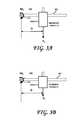
- FIGS. 3A and 3Billustrate the principle of operation of the reference torque assemblies 216 .
- one or more of the plurality of the reference torque assembliesmay be unitary (e.g., molded or assembled into a fixed assembly) device or may be a composite assembly.
- a reference torque assemblymay comprise a rod 302 that is configured to couple to the axle 214 of the HSA swaging tester device 200 .
- a reference weightConnected to the rod 302 at a known distance D from an end thereof is a reference (known) weight (a static load).
- the reference weightis a first reference weight 304 A and in FIG.
- the reference weightis a second reference weight 304 B .
- the reference weight 304 Ais shown to be greater than the reference weight 304 8 . Accordingly, the force vector F A exerted onto the rod 302 in FIG. 3A is greater than the force vector F B exerted onto the rod 302 in FIG. 3B .
- a plurality of such reference torque assembliesmay be provided, each with different reference weights (thereby generating different torques), configured for use in conjunction with the calibration of HSA swaging tester device 200 for use with different types of HSAs having respective different torque out requirements.
- the rod 302acts as a lever arm and the axle 214 defines the axis about which the axle 214 is caused to rotate due to the force vector F A , F B .
- This tendency of the axle 214 to rotate about the axis defined by axle 214 under the influence of the force vector F A , F Bis called torque, moment or moment of force and is shown in FIGS. 3A and 3B as M A and M B .
- the operator Xis the cross product of the scalar D and the force vector F A , F B .
- the magnitude of torque M A , M Bdepends on three quantities: the force F A , F B applied, the length D of the lever arm, and the angle between the force vector F A , F B and the lever arm.
- One embodimentmaintains the aforementioned angle at 90 degrees (relative to the rod 302 ), although reference torque assemblies 216 may be configured with other angles.
- the reference torque assembliesmay be unitary in nature.
- one or more of the reference torque assemblies 216 shown hereinmay comprise a removable rod 302 configured to removably couple to axle 214 connected to the actuator motor 206 and a selected one of a plurality of different reference weights 304 , as shown in FIG. 4 .
- each of the plurality of different reference weights 304may be associated with a respective one of the plurality of types of HSAs to undergo the swaging or testing procedure.
- each of the plurality of different reference weights 304is configured to removably couple to the removable rod 302 at a predetermined distance (such as distance “D” in FIGS. 3A and 3B ) from an end thereof.
- the design of the reference weights 304may be optimized for easy fabrication and for cost reduction. To maintain the length of the cantilever beam (rod 302 ) and the center of gravity of the reference torque assemblies, the reference weights 304 may be designed to have the same cross section for all gauges and different heights. Other configurations and shapes for the reference weights 304 and/or rods 302 are possible.
- the reference torque assembliesmay be configured to be radially repositioned on the axle 214 connected the actuator motor to enable a re-calibration of the force gauge, with reference to the high precision torque sensor 218 , at different radial positions.
- One embodimentis a method for calibrating a swage torque tester.
- a method for calibrating a swage torque testermay comprise affixing a rod 302 of a known length to a torque sensor of a swage torque tester 200 and coupling a known weight 304 to the rod 302 such as to create a reference torque against which the swage torque tester 200 may be calibrated.
- the swage torque tester device 200may then be adjusted until the output torque reading thereof substantially matches the reference torque applied by the reference torque assembly coupled to the rod 302 .
- FIG. 6is a flowchart of a method according to one embodiment. As shown therein, the method may begin at B 61 , whereupon a HSA swaging tester device is provided, as shown at B 62 .
- the HSA swaging tester device(shown at 200 in FIGS. 2A , 2 B and 5 ) may comprise a base 202 , a top tooling assembly 204 connected to the base 202 .
- the top tooling assembly 204may comprise an actuator motor 206 , a load cell 208 connected to the actuator motor 206 and a force gauge 210 connected to the load cell 208 .
- the force gauge 210may be configured to measure torque imparted by the actuator motor 206 on an HSA being manufactured during an HSA swaging procedure (or a previously-manufactured HSA).
- Block B 63calls for calibrating the force gauge according to a selected one of a plurality of types of HSAs to undergo the swaging or testing procedure. This may be carried out, according to one embodiment by coupling a selected one of a plurality of reference torque assemblies 216 to the axle 214 connected the actuator motor 206 , which selected reference torque assembly 216 is configured to impart a known torque onto the axle 214 , as shown at B 64 .
- Block B 65then calls for adjusting the force gauge according to the torque imparted upon the axle 214 by the selected reference torque assembly 216 .
- the methodends at B 67 .
- calibrating in Block B 63may comprise selecting one of the plurality of reference torque assemblies according to the selected type of HSA to undergo the swaging or testing procedure.
- one or more of the plurality of reference torque assembliesmay comprises a removable rod 302 configured to couple to an axle 214 connected to the actuator motor 206 and a selected one of a plurality of different reference weights 304 .
- Each of the plurality of different reference weightsmay be associated with a respective one of the plurality of types of HSAs to undergo the swaging or testing procedure.
- Coupling, in Block B 64may comprise coupling the removable rod 302 to the axle 214 connected to the actuator motor 206 and coupling the selected reference weight 304 to the removable rod 302 at a known distance from an end thereof.
- the methodmay also comprise removing the selected reference torque assembly 216 from the axle 214 coupled to the actuator motor 206 , mounting an HSA of the selected type on the top tooling assembly 204 and carrying out the HSA swaging testing procedure on the mounted HSA with reference to the calibrated force gauge.
- the methodalso encompasses re-adjusting or re-calibrating the HSA swaging tester device 200 by selecting another one of the plurality of reference torque assemblies 216 associated with a selected other one of the plurality of types of HSAs to undergo the swaging or testing procedure and coupling the selected reference torque assembly 216 to the axle 214 connected to the actuator motor 206 .
- the force gaugemay then be calibrated according to this selected other type of HSA to undergo the swaging or testing procedure by adjusting the force gauge according to the torque imparted upon the rod 302 by the selected other one of the plurality of reference torque assemblies 216 .
- the selected other reference torque assembly 216may then be removed from the axle 214 coupled to the actuator motor 206 , another HSA of another type may then be mounted on the top tooling assembly 204 and the HSA swaging or testing procedure may then be carried out on the mounted HSA with reference to the calibrated force gauge. Adjusting may be carried out with a dummy actuator pivot flex assembly (APFA) mounted to the top tooling assembly 204 (instead of, for example, a real HSA that would require destructive testing).
- APFAactuator pivot flex assembly
- the selected reference torque assembly 216may then be radially re-positioned on the axle 214 connected the actuator motor 206 and the force gauge may be re-calibrated with the reference torque assembly 216 positioned at this new radial position on the axle 214 .
- embodimentseliminate operator dependency and reduce the effect of material variation.
- the resultis improved HSA mechanical yield and productivity.
Landscapes
- Physics & Mathematics (AREA)
- General Physics & Mathematics (AREA)
- Testing Of Devices, Machine Parts, Or Other Structures Thereof (AREA)
Abstract
Description
Claims (16)
Priority Applications (1)
| Application Number | Priority Date | Filing Date | Title |
|---|---|---|---|
| US14/299,714US9157817B1 (en) | 2014-06-09 | 2014-06-09 | HSA swage metrology calibration using solid weight gauge and torque sensor |
Applications Claiming Priority (1)
| Application Number | Priority Date | Filing Date | Title |
|---|---|---|---|
| US14/299,714US9157817B1 (en) | 2014-06-09 | 2014-06-09 | HSA swage metrology calibration using solid weight gauge and torque sensor |
Publications (1)
| Publication Number | Publication Date |
|---|---|
| US9157817B1true US9157817B1 (en) | 2015-10-13 |
Family
ID=54252628
Family Applications (1)
| Application Number | Title | Priority Date | Filing Date |
|---|---|---|---|
| US14/299,714Expired - Fee RelatedUS9157817B1 (en) | 2014-06-09 | 2014-06-09 | HSA swage metrology calibration using solid weight gauge and torque sensor |
Country Status (1)
| Country | Link |
|---|---|
| US (1) | US9157817B1 (en) |
Citations (111)
| Publication number | Priority date | Publication date | Assignee | Title |
|---|---|---|---|---|
| US5793634A (en)* | 1997-02-21 | 1998-08-11 | Ethicon, Inc. | Method and system for establishing and monitoring a needle swaging procedure |
| US5948997A (en)* | 1997-09-02 | 1999-09-07 | Intriplex Technologies, Inc. | Swaged connection testing apparatus |
| US6049973A (en) | 1999-04-12 | 2000-04-18 | Western Digital Corporation | Method of assembling an integrated computer module |
| US6225799B1 (en)* | 1998-11-23 | 2001-05-01 | Oleg A. Gergel | Method and apparatus for testing magnetic heads and hard disks |
| US6467153B2 (en) | 1997-06-11 | 2002-10-22 | Western Digital Technologies, Inc. | Method for manufacturing a disk drive |
| US6539818B1 (en)* | 1998-09-14 | 2003-04-01 | The United States Of America As Represented By The Administrator Of The National Aeronautics And Space Administration | Process for testing compaction of a swaged heater for an anode sub-assembly of a hollow cathode assembly |
| US6585256B2 (en)* | 2000-02-07 | 2003-07-01 | Lockheed Martin Corporation | Presentation control for flat article singulation mechanism and sensors suitable for use therewith |
| US6651192B1 (en) | 2000-11-30 | 2003-11-18 | Western Digital Technologies, Inc. | Method and system for testing reliability attributes in disk drives |
| US6657801B1 (en) | 2002-09-30 | 2003-12-02 | Western Digital Technologies, Inc. | Disk drive with improved characterization segment pattern and method of recording the same |
| US6687093B1 (en) | 2001-05-31 | 2004-02-03 | Western Digital Technologies, Inc. | Head stack assembly shipping comb with temporary locating feature for internal head disk assembly build process and disk drive manufactured using the same |
| US6751041B1 (en) | 2002-01-31 | 2004-06-15 | Western Digital Technologies, Inc. | Method and apparatus for selecting servo track writing speed |
| US6788480B1 (en) | 2001-12-22 | 2004-09-07 | Western Digital Technologies, Inc. | Method and apparatus for determining track density during a servo-track writing operation |
| US6791782B1 (en) | 2002-01-31 | 2004-09-14 | Western Digital Technologies, Inc. | Method and apparatus for determining operational spindle rotation rate in a disk drive |
| US6792669B2 (en) | 2001-11-30 | 2004-09-21 | Western Digital Technologies, Inc. | Method for allocating disk drive spindle motors based on an operating characteristic |
| US6798592B1 (en) | 2001-08-31 | 2004-09-28 | Western Digital Technologies, Inc. | Method for reducing position error signal in a disk drive |
| US6894861B1 (en) | 2001-09-28 | 2005-05-17 | Western Digital Technologies, Inc. | Method for reducing written-in runout during servo track writing of a disk drive |
| US6898044B1 (en) | 2003-04-30 | 2005-05-24 | Western Digital Technologies, Inc. | Method for calculating a format specific parameter in a disk drive having differing surface formats |
| US6897393B1 (en) | 2002-04-30 | 2005-05-24 | Western Digital Technologies, Inc. | Methods for reducing costs and increasing throughput in the manufacture of disk drives by categorizing the disk drives based upon measured disk pack imbalance |
| US6943972B1 (en) | 2003-06-27 | 2005-09-13 | Western Digital Technologies, Inc. | Selecting a track density for each disk surface of a disk drive based on head characteristic |
| US7003626B1 (en) | 2003-05-30 | 2006-02-21 | Western Digital Technologies, Inc. | Method for storing format specific data in a microcontroller execution memory |
| US7027242B1 (en) | 2004-09-23 | 2006-04-11 | Western Digital (Fremont), Inc. | Method and apparatus for measuring write-induced pole tip protrusion |
| US7046467B1 (en) | 2003-04-30 | 2006-05-16 | Western Digital Technologies, Inc. | Method for generating a format specific data structure in a disk drive having differing surface formats |
| US7058759B1 (en) | 2003-03-31 | 2006-06-06 | Western Digital Technologies, Inc. | Configuring a disk drive to support a targeted storage format |
| US7072129B1 (en) | 2004-06-30 | 2006-07-04 | Western Digital Technologies, Inc. | Identifying defective data sectors in a disk drive |
| US7076603B1 (en) | 2003-03-31 | 2006-07-11 | Western Digital Technologies, Inc. | Method for mapping a selected sector to a zone on a disk |
| US7076391B1 (en) | 2002-10-31 | 2006-07-11 | Western Digital Technologies, Inc. | Methods and systems for asynchronously testing a plurality of disk drives |
| US7136242B1 (en) | 2004-12-09 | 2006-11-14 | Western Digital Technologies, Inc. | Servo writing substantially linear servo wedges to reduce overwrite effect in perpendicular magnetic recording |
| US7139145B1 (en) | 2004-09-23 | 2006-11-21 | Western Digital Technologies, Inc. | Cluster-based defect detection testing for disk drives |
| US7145744B1 (en) | 2005-08-03 | 2006-12-05 | Western Digital Technologies, Inc. | Reducing spiral write time and clock track drift while writing spiral reference patterns to a disk of a disk drive |
| US7178432B1 (en) | 2005-11-30 | 2007-02-20 | Western Digital Technologies, Inc. | Methods, devices and systems for screw feeding by vacuum and gravity |
| US7199959B1 (en) | 2004-12-13 | 2007-04-03 | Western Digital Technologies, Inc. | Repeatable timing error correction system for use in a servo writer |
| US7203020B1 (en) | 2005-10-07 | 2007-04-10 | Western Digital Technologies, Inc. | System and method for particle monitoring for a head disk assembly to detect a head disk interface event |
| US7209310B1 (en) | 2005-07-25 | 2007-04-24 | Western Digital Technologies, Inc. | Disk drive identifying starting track by performing multiple load operations |
| US7222410B1 (en) | 2004-10-27 | 2007-05-29 | Western Digital Technologies, Inc. | Method of assembly of a disk drive including engaging first and second VCM plates while maintaining a holding force against the first VCM plate |
| US7236911B1 (en) | 2004-06-16 | 2007-06-26 | Western Digital Technologies, Inc. | Using a genetic algorithm to select a subset of quality metrics as input to a disk drive failure prediction algorithm |
| US7269525B1 (en) | 2004-06-16 | 2007-09-11 | Western Digital Technologies, Inc. | Binning disk drives during manufacturing by evaluating quality metrics prior to a final quality audit |
| US20080084630A1 (en) | 2006-10-05 | 2008-04-10 | Western Digital Technologies, Inc. | Media cover for manufacturing a disk drive |
| US7458282B1 (en) | 2006-11-21 | 2008-12-02 | Western Digital Technologies, Inc. | Screwdriver comprising a slider having an attached screw bit and a position detector for position feedback |
| US7490398B1 (en) | 2006-02-22 | 2009-02-17 | Western Digital Technologies, Inc. | Methods for assembling a disk drive using robotic end effector |
| US7506553B1 (en) | 2007-06-18 | 2009-03-24 | Western Digital Technologies, Inc. | Methods, devices and systems for adaptively driving screws using a screw driving tool |
| US20090157848A1 (en) | 2007-12-18 | 2009-06-18 | Western Digital Technologies, Inc. | Application server processing tcp/ip requests from a client by invoking an asynchronous function |
| US7549204B1 (en) | 2005-11-30 | 2009-06-23 | Western Digital Technologies, Inc. | Methods for picking and placing workpieces into small form factor hard disk drives |
| US7552526B1 (en) | 2005-01-12 | 2009-06-30 | Western Digital Technologies, Inc. | Tooling mandrel for assembling a head stack assembly with a disk drive base |
| US7561416B1 (en) | 2006-12-15 | 2009-07-14 | Western Digital Technologies, Inc. | Storage device fixture with simultaneous unload mechanism |
| US7559590B1 (en) | 2005-10-19 | 2009-07-14 | Western Digital Technologies, Inc. | Pressure transmission assembly for mounting to a robotic device having a rotatable end effector |
| US7596722B1 (en) | 2006-02-14 | 2009-09-29 | Western Digital Technologies, Inc. | Asynchronous automatic software module updates in a multi-cell disk drive test system |
| US7634375B1 (en) | 2002-10-31 | 2009-12-15 | Western Digital Technologies, Inc. | Multi-drive adaptor for use in a slot of a disk drive test system |
| US7653983B1 (en) | 2007-06-26 | 2010-02-02 | Western Digital Technologies, Inc. | Manufacturing assembly for manufacturing a disk drive |
| US7669711B1 (en) | 2005-10-19 | 2010-03-02 | Western Digital Technologies, Inc. | Disk pack balancing station |
| US7671599B1 (en) | 2007-01-31 | 2010-03-02 | Western Digital Technologies, Inc. | Static electricity monitor comprising a walking footpad electrode and handrail electrode |
| US7673638B1 (en) | 2006-06-16 | 2010-03-09 | Western Digital Technologies, Inc. | System and method to monitor particles removed from a component |
| US7690705B1 (en) | 2006-12-21 | 2010-04-06 | Western Digital Technologies, Inc. | Vacuum chuck useful for affixing cover seals to hard disk drives |
| US7694410B2 (en)* | 2001-11-13 | 2010-04-13 | Sae Magnetics (H.K.) Ltd. | Process for testing a head stack assembly |
| US20100108256A1 (en) | 2008-11-05 | 2010-05-06 | Western Digital Technologies, Inc. | Closed loop control of adhesive dot characteristics |
| US7863889B1 (en) | 2007-02-06 | 2011-01-04 | Western Digital Technologies, Inc. | Component receptacle to segregate components |
| US7869182B1 (en) | 2006-08-23 | 2011-01-11 | Western Digital Technologies, Inc. | Monitoring device for use with an insulated dual portion garment |
| US7896218B2 (en) | 2007-06-28 | 2011-03-01 | Western Digital Technologies, Inc. | Apparatus and method for conductive metal ball bonding with electrostatic discharge detection |
| US7900272B1 (en) | 2006-08-23 | 2011-03-08 | Western Digital Technologies, Inc. | Static control garment |
| US7912666B1 (en) | 2005-11-28 | 2011-03-22 | Western Digital Technologies, Inc. | Disk drive grouping in a multi-cell disk drive test system |
| US7916599B1 (en) | 2008-05-23 | 2011-03-29 | Western Digital Technologies, Inc. | Method to balance spindles in a plurality of disk drives |
| US7940487B1 (en) | 2008-06-24 | 2011-05-10 | Western Digital Technologies, Inc. | Heating a head disk assembly for a time interval prior to writing spiral servo tracks to the disk |
| US7974038B2 (en) | 2007-12-10 | 2011-07-05 | Western Digital Technologies, Inc. | Servo writer with retract capacitor for generating a VCM driving current during a power failure |
| US7980159B1 (en) | 2005-11-30 | 2011-07-19 | Western Digital Technologies, Inc. | Methods, devices and systems for screw feeding by vacuum and gravity |
| US8078421B1 (en) | 2007-12-19 | 2011-12-13 | Western Digital Technologies, Inc. | Multi-cell disk drive test system providing a power recovery mode |
| US8094414B1 (en) | 2009-07-09 | 2012-01-10 | Western Digital Technologies, Inc. | Head gimbal assembly mounting mechanism |
| US8092610B1 (en) | 2010-12-21 | 2012-01-10 | Western Digital Technologies, Inc. | Apparatus and method for cleaning a driver used in disk drive manufacturing |
| US8098460B1 (en) | 2009-06-30 | 2012-01-17 | Western Digital Technologies, Inc. | Dual-state clamping mechanism |
| US8135208B1 (en) | 2009-01-15 | 2012-03-13 | Western Digital Technologies, Inc. | Calibrated vision based robotic system utilizing upward and downward looking cameras |
| US8162366B1 (en) | 2010-03-26 | 2012-04-24 | Western Digital Technologies, Inc. | Systems and methods for gripping a component |
| US8168033B1 (en) | 2007-06-12 | 2012-05-01 | Western Digital Technologies, Inc. | Methods and devices for printing and affixing an individual label onto an item having a machine readable code thereon |
| US8180487B1 (en) | 2008-09-30 | 2012-05-15 | Western Digital Technologies, Inc. | Calibrated vision based robotic system |
| US8199425B1 (en) | 2009-05-29 | 2012-06-12 | Western Digital Technologies, Inc. | Method to replace gas in a disk drive |
| US8218256B1 (en) | 2009-10-30 | 2012-07-10 | Western Digital Technologies, Inc. | Disk spindle assembly cartridge |
| US8223448B1 (en) | 2010-04-22 | 2012-07-17 | Western Digital Technologies, Inc. | Disk drive calibrating preamp for servo sectors and data sectors |
| US8230570B1 (en) | 2009-06-12 | 2012-07-31 | Western Digital Technologies, Inc. | Automatic gravity vacuum screw feeding |
| US8245601B1 (en) | 2010-03-31 | 2012-08-21 | Western Digital Technologies, Inc. | Screwdriver sleeve finder |
| US8270118B1 (en) | 2009-10-30 | 2012-09-18 | Western Digital Technologies, Inc. | Head stack assembly cartridge |
| US8267831B1 (en) | 2009-05-19 | 2012-09-18 | Western Digital Technologies, Inc. | Method and apparatus for washing, etching, rinsing, and plating substrates |
| US8300338B1 (en) | 2010-09-30 | 2012-10-30 | Western Digital Technologies, Inc. | Disk drive correlating different fly height measurements to verify disk warpage |
| US8307537B1 (en) | 2005-10-24 | 2012-11-13 | Western Digital Technologies, Inc. | Method of using a tooling mandrel for assembling a disk drive |
| US8322235B1 (en) | 2011-02-18 | 2012-12-04 | Western Digital Technologies, Inc. | Microactuator test assembly comprising a spreader pin for engaging a load beam of an actuator arm |
| US8327529B1 (en) | 2010-06-04 | 2012-12-11 | Western Digital Technologies, Inc. | Assembly tool system |
| US8335049B1 (en) | 2010-06-07 | 2012-12-18 | Western Digital Technologies, Inc. | Disk drive detecting crack in microactuator |
| US8345367B1 (en) | 2010-12-23 | 2013-01-01 | Western Digital Technologies, Inc. | Recording defects on a hard drive |
| US8356384B1 (en) | 2010-06-30 | 2013-01-22 | Western Digital Technologies, Inc. | Hard drive assembly tools for evacuating particles |
| US8369073B2 (en) | 2010-09-30 | 2013-02-05 | Western Digital Technologies, Inc. | Systems and methods for connecting multiple hard drives |
| US8379363B1 (en) | 2010-03-26 | 2013-02-19 | Western Digital Technologies, Inc. | Bulk erase tool to erase a perpendicular media recording disk of a disk drive |
| US8387631B1 (en) | 2008-12-10 | 2013-03-05 | Western Digital Technologies, Inc. | HDA vacuum cleaning machine for manufacturing of HDD |
| US20130057986A1 (en) | 2011-09-06 | 2013-03-07 | Western Digital Technologies, Inc. | System and method to align a boss of a head gimbal assembly to a boss hole of an actuator arm for disk drive assembly |
| US8424824B1 (en) | 2009-12-22 | 2013-04-23 | Western Digital Technologies, Inc. | Balancer swivel arm assembly |
| US8424418B1 (en) | 2010-09-30 | 2013-04-23 | Western Digital Technologies, Inc. | Systems and methods for coupling screwdrivers to screw finders |
| US8432630B1 (en) | 2010-06-30 | 2013-04-30 | Western Digital Technologies, Inc. | Disk drive component test system |
| US8447551B1 (en) | 2010-06-30 | 2013-05-21 | Western Digital Technologies, Inc. | Hard drive assembly tool calibration verification |
| US8447430B1 (en) | 2010-06-30 | 2013-05-21 | Western Digital Technologies, Inc. | Systems and methods for assembly tool calibration verification |
| US8451578B1 (en) | 2010-02-12 | 2013-05-28 | Western Digital Technologies, Inc. | Hard drive particle cleaning system and method |
| US8453841B1 (en) | 2009-04-23 | 2013-06-04 | Western Digital Technologies, Inc. | Disk placement and storage assembly with disk cassette and disk slotter |
| US8485772B1 (en) | 2010-02-24 | 2013-07-16 | Western Digital Technologies, Inc. | Media flip and cassette exchange apparatus and method |
| US8493681B1 (en) | 2010-11-23 | 2013-07-23 | Western Digital Technologies, Inc. | Disk drive generating map of margin rectangles around defects |
| US8537480B1 (en) | 2010-11-23 | 2013-09-17 | Western Digital Technologies, Inc. | Hard drive testing |
| US20130248545A1 (en) | 2012-03-23 | 2013-09-26 | Western Digital Technologies, Inc. | Fastener container to provide fasteners to a fastener feeder |
| US8547657B1 (en) | 2010-06-10 | 2013-10-01 | Western Digital Technologies, Inc. | Disk drive detecting defective microactuator |
| US8553968B1 (en) | 2005-02-18 | 2013-10-08 | Western Digital Technologies, Inc. | Using optical character recognition augmented by an error correction code to detect serial numbers written on a wafer |
| US8565511B1 (en) | 2010-12-22 | 2013-10-22 | Western Digital Technologies, Inc. | Apparatus and method to align a manufacturing device having an end effecter and fixture in a parallel manner |
| US8582229B1 (en) | 2010-09-27 | 2013-11-12 | Western Digital Technologies, Inc. | Pushpin assembly |
| US8596107B1 (en) | 2010-03-30 | 2013-12-03 | Western Digital Technologies, Inc. | Correlation standard for calibrating a scanning electron microscope |
| US8605383B1 (en) | 2012-05-21 | 2013-12-10 | Western Digital Technologies, Inc. | Methods, devices and systems for characterizing polarities of piezoelectric (PZT) elements of a two PZT element microactuator |
| US8640328B1 (en) | 2010-06-18 | 2014-02-04 | Western Digital Technologies, Inc. | Systems for fastening a head stack to a hard drive base assembly |
| US8653824B1 (en) | 2009-12-16 | 2014-02-18 | Western Digital (Fremont), Llc | Delta temperature test method and system |
| US8650716B1 (en) | 2011-12-13 | 2014-02-18 | Western Digital Technologies, Inc. | Methods and apparatus for minimizing contamination in hard disk drive assembly processes |
| US8662554B1 (en) | 2011-12-20 | 2014-03-04 | Western Digital Technologies, Inc. | Vacuum pick-up end effecter to pick and place a component in a manufacturing process |
| US8683676B1 (en) | 2011-04-29 | 2014-04-01 | Western Digital Technologies, Inc. | Apparatus and method to grip a disk clamp of a disk drive |
- 2014
- 2014-06-09USUS14/299,714patent/US9157817B1/ennot_activeExpired - Fee Related
Patent Citations (124)
| Publication number | Priority date | Publication date | Assignee | Title |
|---|---|---|---|---|
| US5793634A (en)* | 1997-02-21 | 1998-08-11 | Ethicon, Inc. | Method and system for establishing and monitoring a needle swaging procedure |
| US6467153B2 (en) | 1997-06-11 | 2002-10-22 | Western Digital Technologies, Inc. | Method for manufacturing a disk drive |
| US5948997A (en)* | 1997-09-02 | 1999-09-07 | Intriplex Technologies, Inc. | Swaged connection testing apparatus |
| US6539818B1 (en)* | 1998-09-14 | 2003-04-01 | The United States Of America As Represented By The Administrator Of The National Aeronautics And Space Administration | Process for testing compaction of a swaged heater for an anode sub-assembly of a hollow cathode assembly |
| US6225799B1 (en)* | 1998-11-23 | 2001-05-01 | Oleg A. Gergel | Method and apparatus for testing magnetic heads and hard disks |
| US6049973A (en) | 1999-04-12 | 2000-04-18 | Western Digital Corporation | Method of assembling an integrated computer module |
| US6585256B2 (en)* | 2000-02-07 | 2003-07-01 | Lockheed Martin Corporation | Presentation control for flat article singulation mechanism and sensors suitable for use therewith |
| US6651192B1 (en) | 2000-11-30 | 2003-11-18 | Western Digital Technologies, Inc. | Method and system for testing reliability attributes in disk drives |
| US6687093B1 (en) | 2001-05-31 | 2004-02-03 | Western Digital Technologies, Inc. | Head stack assembly shipping comb with temporary locating feature for internal head disk assembly build process and disk drive manufactured using the same |
| US6798592B1 (en) | 2001-08-31 | 2004-09-28 | Western Digital Technologies, Inc. | Method for reducing position error signal in a disk drive |
| US6894861B1 (en) | 2001-09-28 | 2005-05-17 | Western Digital Technologies, Inc. | Method for reducing written-in runout during servo track writing of a disk drive |
| US7694410B2 (en)* | 2001-11-13 | 2010-04-13 | Sae Magnetics (H.K.) Ltd. | Process for testing a head stack assembly |
| US6792669B2 (en) | 2001-11-30 | 2004-09-21 | Western Digital Technologies, Inc. | Method for allocating disk drive spindle motors based on an operating characteristic |
| US6788480B1 (en) | 2001-12-22 | 2004-09-07 | Western Digital Technologies, Inc. | Method and apparatus for determining track density during a servo-track writing operation |
| US6791782B1 (en) | 2002-01-31 | 2004-09-14 | Western Digital Technologies, Inc. | Method and apparatus for determining operational spindle rotation rate in a disk drive |
| US6751041B1 (en) | 2002-01-31 | 2004-06-15 | Western Digital Technologies, Inc. | Method and apparatus for selecting servo track writing speed |
| US6897393B1 (en) | 2002-04-30 | 2005-05-24 | Western Digital Technologies, Inc. | Methods for reducing costs and increasing throughput in the manufacture of disk drives by categorizing the disk drives based upon measured disk pack imbalance |
| US6657801B1 (en) | 2002-09-30 | 2003-12-02 | Western Digital Technologies, Inc. | Disk drive with improved characterization segment pattern and method of recording the same |
| US7076391B1 (en) | 2002-10-31 | 2006-07-11 | Western Digital Technologies, Inc. | Methods and systems for asynchronously testing a plurality of disk drives |
| US7634375B1 (en) | 2002-10-31 | 2009-12-15 | Western Digital Technologies, Inc. | Multi-drive adaptor for use in a slot of a disk drive test system |
| US7058759B1 (en) | 2003-03-31 | 2006-06-06 | Western Digital Technologies, Inc. | Configuring a disk drive to support a targeted storage format |
| US7076603B1 (en) | 2003-03-31 | 2006-07-11 | Western Digital Technologies, Inc. | Method for mapping a selected sector to a zone on a disk |
| US6898044B1 (en) | 2003-04-30 | 2005-05-24 | Western Digital Technologies, Inc. | Method for calculating a format specific parameter in a disk drive having differing surface formats |
| US7046467B1 (en) | 2003-04-30 | 2006-05-16 | Western Digital Technologies, Inc. | Method for generating a format specific data structure in a disk drive having differing surface formats |
| US7003626B1 (en) | 2003-05-30 | 2006-02-21 | Western Digital Technologies, Inc. | Method for storing format specific data in a microcontroller execution memory |
| US6943972B1 (en) | 2003-06-27 | 2005-09-13 | Western Digital Technologies, Inc. | Selecting a track density for each disk surface of a disk drive based on head characteristic |
| US7236911B1 (en) | 2004-06-16 | 2007-06-26 | Western Digital Technologies, Inc. | Using a genetic algorithm to select a subset of quality metrics as input to a disk drive failure prediction algorithm |
| US7269525B1 (en) | 2004-06-16 | 2007-09-11 | Western Digital Technologies, Inc. | Binning disk drives during manufacturing by evaluating quality metrics prior to a final quality audit |
| US7072129B1 (en) | 2004-06-30 | 2006-07-04 | Western Digital Technologies, Inc. | Identifying defective data sectors in a disk drive |
| US7139145B1 (en) | 2004-09-23 | 2006-11-21 | Western Digital Technologies, Inc. | Cluster-based defect detection testing for disk drives |
| US7027242B1 (en) | 2004-09-23 | 2006-04-11 | Western Digital (Fremont), Inc. | Method and apparatus for measuring write-induced pole tip protrusion |
| US7222410B1 (en) | 2004-10-27 | 2007-05-29 | Western Digital Technologies, Inc. | Method of assembly of a disk drive including engaging first and second VCM plates while maintaining a holding force against the first VCM plate |
| US7136242B1 (en) | 2004-12-09 | 2006-11-14 | Western Digital Technologies, Inc. | Servo writing substantially linear servo wedges to reduce overwrite effect in perpendicular magnetic recording |
| US7199959B1 (en) | 2004-12-13 | 2007-04-03 | Western Digital Technologies, Inc. | Repeatable timing error correction system for use in a servo writer |
| US7743486B1 (en) | 2005-01-12 | 2010-06-29 | Western Digital Technologies, Inc. | Method for assembling a head stack assembly with a disk drive base utilizing a tooling mandrel |
| US7552526B1 (en) | 2005-01-12 | 2009-06-30 | Western Digital Technologies, Inc. | Tooling mandrel for assembling a head stack assembly with a disk drive base |
| US8553968B1 (en) | 2005-02-18 | 2013-10-08 | Western Digital Technologies, Inc. | Using optical character recognition augmented by an error correction code to detect serial numbers written on a wafer |
| US7209310B1 (en) | 2005-07-25 | 2007-04-24 | Western Digital Technologies, Inc. | Disk drive identifying starting track by performing multiple load operations |
| US7145744B1 (en) | 2005-08-03 | 2006-12-05 | Western Digital Technologies, Inc. | Reducing spiral write time and clock track drift while writing spiral reference patterns to a disk of a disk drive |
| US7203020B1 (en) | 2005-10-07 | 2007-04-10 | Western Digital Technologies, Inc. | System and method for particle monitoring for a head disk assembly to detect a head disk interface event |
| US7874424B1 (en) | 2005-10-19 | 2011-01-25 | Western Digital Technologies, Inc. | Disk pack balancing station |
| US7669711B1 (en) | 2005-10-19 | 2010-03-02 | Western Digital Technologies, Inc. | Disk pack balancing station |
| US7559590B1 (en) | 2005-10-19 | 2009-07-14 | Western Digital Technologies, Inc. | Pressure transmission assembly for mounting to a robotic device having a rotatable end effector |
| US8307537B1 (en) | 2005-10-24 | 2012-11-13 | Western Digital Technologies, Inc. | Method of using a tooling mandrel for assembling a disk drive |
| US7912666B1 (en) | 2005-11-28 | 2011-03-22 | Western Digital Technologies, Inc. | Disk drive grouping in a multi-cell disk drive test system |
| US7980159B1 (en) | 2005-11-30 | 2011-07-19 | Western Digital Technologies, Inc. | Methods, devices and systems for screw feeding by vacuum and gravity |
| US8561285B1 (en) | 2005-11-30 | 2013-10-22 | Western Digital Technologies, Inc. | Methods and devices for picking and placing workpieces into small form factor hard disk drives |
| US7549204B1 (en) | 2005-11-30 | 2009-06-23 | Western Digital Technologies, Inc. | Methods for picking and placing workpieces into small form factor hard disk drives |
| US7178432B1 (en) | 2005-11-30 | 2007-02-20 | Western Digital Technologies, Inc. | Methods, devices and systems for screw feeding by vacuum and gravity |
| US8127643B1 (en) | 2005-11-30 | 2012-03-06 | Western Digital Technologies, Inc. | Methods, devices and systems for screw feeding by vacuum and gravity |
| US7596722B1 (en) | 2006-02-14 | 2009-09-29 | Western Digital Technologies, Inc. | Asynchronous automatic software module updates in a multi-cell disk drive test system |
| US7987585B1 (en) | 2006-02-22 | 2011-08-02 | Western Digital Technologies, Inc. | System for assembling a disk drive using a robotic end effector |
| US7490398B1 (en) | 2006-02-22 | 2009-02-17 | Western Digital Technologies, Inc. | Methods for assembling a disk drive using robotic end effector |
| US7673638B1 (en) | 2006-06-16 | 2010-03-09 | Western Digital Technologies, Inc. | System and method to monitor particles removed from a component |
| US7900272B1 (en) | 2006-08-23 | 2011-03-08 | Western Digital Technologies, Inc. | Static control garment |
| US7869183B1 (en) | 2006-08-23 | 2011-01-11 | Western Digital Technologies, Inc. | Static electricity monitoring device comprising a first footpad electrically insulated from a second footpad |
| US7869182B1 (en) | 2006-08-23 | 2011-01-11 | Western Digital Technologies, Inc. | Monitoring device for use with an insulated dual portion garment |
| US7921543B2 (en) | 2006-10-05 | 2011-04-12 | Western Digital Technologies, Inc. | Method of manufacturing a disk drive using a media cover |
| US20080084630A1 (en) | 2006-10-05 | 2008-04-10 | Western Digital Technologies, Inc. | Media cover for manufacturing a disk drive |
| US7458282B1 (en) | 2006-11-21 | 2008-12-02 | Western Digital Technologies, Inc. | Screwdriver comprising a slider having an attached screw bit and a position detector for position feedback |
| US7561416B1 (en) | 2006-12-15 | 2009-07-14 | Western Digital Technologies, Inc. | Storage device fixture with simultaneous unload mechanism |
| US7690705B1 (en) | 2006-12-21 | 2010-04-06 | Western Digital Technologies, Inc. | Vacuum chuck useful for affixing cover seals to hard disk drives |
| US7671599B1 (en) | 2007-01-31 | 2010-03-02 | Western Digital Technologies, Inc. | Static electricity monitor comprising a walking footpad electrode and handrail electrode |
| US7863889B1 (en) | 2007-02-06 | 2011-01-04 | Western Digital Technologies, Inc. | Component receptacle to segregate components |
| US8168033B1 (en) | 2007-06-12 | 2012-05-01 | Western Digital Technologies, Inc. | Methods and devices for printing and affixing an individual label onto an item having a machine readable code thereon |
| US7506553B1 (en) | 2007-06-18 | 2009-03-24 | Western Digital Technologies, Inc. | Methods, devices and systems for adaptively driving screws using a screw driving tool |
| US7653983B1 (en) | 2007-06-26 | 2010-02-02 | Western Digital Technologies, Inc. | Manufacturing assembly for manufacturing a disk drive |
| US8066171B1 (en) | 2007-06-28 | 2011-11-29 | Western Digital Technologies, Inc. | Conductive metal ball bonding with electrostatic discharge detection |
| US7896218B2 (en) | 2007-06-28 | 2011-03-01 | Western Digital Technologies, Inc. | Apparatus and method for conductive metal ball bonding with electrostatic discharge detection |
| US7974038B2 (en) | 2007-12-10 | 2011-07-05 | Western Digital Technologies, Inc. | Servo writer with retract capacitor for generating a VCM driving current during a power failure |
| US20090157848A1 (en) | 2007-12-18 | 2009-06-18 | Western Digital Technologies, Inc. | Application server processing tcp/ip requests from a client by invoking an asynchronous function |
| US8078421B1 (en) | 2007-12-19 | 2011-12-13 | Western Digital Technologies, Inc. | Multi-cell disk drive test system providing a power recovery mode |
| US7916599B1 (en) | 2008-05-23 | 2011-03-29 | Western Digital Technologies, Inc. | Method to balance spindles in a plurality of disk drives |
| US7940487B1 (en) | 2008-06-24 | 2011-05-10 | Western Digital Technologies, Inc. | Heating a head disk assembly for a time interval prior to writing spiral servo tracks to the disk |
| US8180487B1 (en) | 2008-09-30 | 2012-05-15 | Western Digital Technologies, Inc. | Calibrated vision based robotic system |
| US20100108256A1 (en) | 2008-11-05 | 2010-05-06 | Western Digital Technologies, Inc. | Closed loop control of adhesive dot characteristics |
| US8387631B1 (en) | 2008-12-10 | 2013-03-05 | Western Digital Technologies, Inc. | HDA vacuum cleaning machine for manufacturing of HDD |
| US8135208B1 (en) | 2009-01-15 | 2012-03-13 | Western Digital Technologies, Inc. | Calibrated vision based robotic system utilizing upward and downward looking cameras |
| US8453841B1 (en) | 2009-04-23 | 2013-06-04 | Western Digital Technologies, Inc. | Disk placement and storage assembly with disk cassette and disk slotter |
| US8267831B1 (en) | 2009-05-19 | 2012-09-18 | Western Digital Technologies, Inc. | Method and apparatus for washing, etching, rinsing, and plating substrates |
| US8199425B1 (en) | 2009-05-29 | 2012-06-12 | Western Digital Technologies, Inc. | Method to replace gas in a disk drive |
| US8230570B1 (en) | 2009-06-12 | 2012-07-31 | Western Digital Technologies, Inc. | Automatic gravity vacuum screw feeding |
| US8689433B1 (en) | 2009-06-12 | 2014-04-08 | Western Digital Technologies, Inc. | Automatic gravity vacuum screw feeding |
| US8098460B1 (en) | 2009-06-30 | 2012-01-17 | Western Digital Technologies, Inc. | Dual-state clamping mechanism |
| US8094414B1 (en) | 2009-07-09 | 2012-01-10 | Western Digital Technologies, Inc. | Head gimbal assembly mounting mechanism |
| US8218256B1 (en) | 2009-10-30 | 2012-07-10 | Western Digital Technologies, Inc. | Disk spindle assembly cartridge |
| US8544164B1 (en) | 2009-10-30 | 2013-10-01 | Western Digital Technologies, Inc. | Method for test mounting a head stack assembly cartridge |
| US8270118B1 (en) | 2009-10-30 | 2012-09-18 | Western Digital Technologies, Inc. | Head stack assembly cartridge |
| US8432631B1 (en) | 2009-10-30 | 2013-04-30 | Western Digital Technologies, Inc. | Disk spindle assembly cartridge |
| US8653824B1 (en) | 2009-12-16 | 2014-02-18 | Western Digital (Fremont), Llc | Delta temperature test method and system |
| US8424824B1 (en) | 2009-12-22 | 2013-04-23 | Western Digital Technologies, Inc. | Balancer swivel arm assembly |
| US8451578B1 (en) | 2010-02-12 | 2013-05-28 | Western Digital Technologies, Inc. | Hard drive particle cleaning system and method |
| US8485772B1 (en) | 2010-02-24 | 2013-07-16 | Western Digital Technologies, Inc. | Media flip and cassette exchange apparatus and method |
| US8379363B1 (en) | 2010-03-26 | 2013-02-19 | Western Digital Technologies, Inc. | Bulk erase tool to erase a perpendicular media recording disk of a disk drive |
| US8162366B1 (en) | 2010-03-26 | 2012-04-24 | Western Digital Technologies, Inc. | Systems and methods for gripping a component |
| US8596107B1 (en) | 2010-03-30 | 2013-12-03 | Western Digital Technologies, Inc. | Correlation standard for calibrating a scanning electron microscope |
| US8245601B1 (en) | 2010-03-31 | 2012-08-21 | Western Digital Technologies, Inc. | Screwdriver sleeve finder |
| US8223448B1 (en) | 2010-04-22 | 2012-07-17 | Western Digital Technologies, Inc. | Disk drive calibrating preamp for servo sectors and data sectors |
| US8327529B1 (en) | 2010-06-04 | 2012-12-11 | Western Digital Technologies, Inc. | Assembly tool system |
| US8454755B1 (en) | 2010-06-04 | 2013-06-04 | Western Digital Technologies, Inc. | Methods for evacuating particles from a hard drive component |
| US8335049B1 (en) | 2010-06-07 | 2012-12-18 | Western Digital Technologies, Inc. | Disk drive detecting crack in microactuator |
| US8547657B1 (en) | 2010-06-10 | 2013-10-01 | Western Digital Technologies, Inc. | Disk drive detecting defective microactuator |
| US8640328B1 (en) | 2010-06-18 | 2014-02-04 | Western Digital Technologies, Inc. | Systems for fastening a head stack to a hard drive base assembly |
| US8432630B1 (en) | 2010-06-30 | 2013-04-30 | Western Digital Technologies, Inc. | Disk drive component test system |
| US8447551B1 (en) | 2010-06-30 | 2013-05-21 | Western Digital Technologies, Inc. | Hard drive assembly tool calibration verification |
| US8356384B1 (en) | 2010-06-30 | 2013-01-22 | Western Digital Technologies, Inc. | Hard drive assembly tools for evacuating particles |
| US8447430B1 (en) | 2010-06-30 | 2013-05-21 | Western Digital Technologies, Inc. | Systems and methods for assembly tool calibration verification |
| US8582229B1 (en) | 2010-09-27 | 2013-11-12 | Western Digital Technologies, Inc. | Pushpin assembly |
| US8424418B1 (en) | 2010-09-30 | 2013-04-23 | Western Digital Technologies, Inc. | Systems and methods for coupling screwdrivers to screw finders |
| US8300338B1 (en) | 2010-09-30 | 2012-10-30 | Western Digital Technologies, Inc. | Disk drive correlating different fly height measurements to verify disk warpage |
| US8369073B2 (en) | 2010-09-30 | 2013-02-05 | Western Digital Technologies, Inc. | Systems and methods for connecting multiple hard drives |
| US8493681B1 (en) | 2010-11-23 | 2013-07-23 | Western Digital Technologies, Inc. | Disk drive generating map of margin rectangles around defects |
| US8537480B1 (en) | 2010-11-23 | 2013-09-17 | Western Digital Technologies, Inc. | Hard drive testing |
| US8312585B1 (en) | 2010-12-21 | 2012-11-20 | Western Digital Technologies, Inc. | Apparatus and method for cleaning a driver used in disk drive manufacturing |
| US8092610B1 (en) | 2010-12-21 | 2012-01-10 | Western Digital Technologies, Inc. | Apparatus and method for cleaning a driver used in disk drive manufacturing |
| US8565511B1 (en) | 2010-12-22 | 2013-10-22 | Western Digital Technologies, Inc. | Apparatus and method to align a manufacturing device having an end effecter and fixture in a parallel manner |
| US8345367B1 (en) | 2010-12-23 | 2013-01-01 | Western Digital Technologies, Inc. | Recording defects on a hard drive |
| US8322235B1 (en) | 2011-02-18 | 2012-12-04 | Western Digital Technologies, Inc. | Microactuator test assembly comprising a spreader pin for engaging a load beam of an actuator arm |
| US8683676B1 (en) | 2011-04-29 | 2014-04-01 | Western Digital Technologies, Inc. | Apparatus and method to grip a disk clamp of a disk drive |
| US20130057986A1 (en) | 2011-09-06 | 2013-03-07 | Western Digital Technologies, Inc. | System and method to align a boss of a head gimbal assembly to a boss hole of an actuator arm for disk drive assembly |
| US8650716B1 (en) | 2011-12-13 | 2014-02-18 | Western Digital Technologies, Inc. | Methods and apparatus for minimizing contamination in hard disk drive assembly processes |
| US8662554B1 (en) | 2011-12-20 | 2014-03-04 | Western Digital Technologies, Inc. | Vacuum pick-up end effecter to pick and place a component in a manufacturing process |
| US20130248545A1 (en) | 2012-03-23 | 2013-09-26 | Western Digital Technologies, Inc. | Fastener container to provide fasteners to a fastener feeder |
| US8605383B1 (en) | 2012-05-21 | 2013-12-10 | Western Digital Technologies, Inc. | Methods, devices and systems for characterizing polarities of piezoelectric (PZT) elements of a two PZT element microactuator |
Similar Documents
| Publication | Publication Date | Title |
|---|---|---|
| EP3076153B1 (en) | Method for calculating an indenter area function and quantifying a deviation from the ideal shape of an indenter | |
| CN100570273C (en) | A resistance strain type diameter measuring device and its application method | |
| CN104376211A (en) | Method for assessing measurement uncertainty of coordinate measuring machine | |
| JPH02284216A (en) | Analog probe correcting method and instrument for the same | |
| CN109684730B (en) | Bridge damage identification method based on quasi-static deflection curved surface method | |
| EP1877732A2 (en) | Probe calibration | |
| CN107153029B (en) | Device and method for testing tangential rigidity of wheel disc joint surface | |
| CN107101935B (en) | Method for measuring normal contact stiffness | |
| CN203758495U (en) | Clamping device suitable for rock deformation testing sensor calibration | |
| CN117074181B (en) | Pressure testing method, device and equipment for curved flexible screen and storage medium | |
| US7506552B2 (en) | Micro torque and micro stiffness measurement device | |
| JP2002543549A (en) | Method and apparatus for balancing a spindle in a hard disk drive | |
| KR100932454B1 (en) | Residual stress measuring equipment calibration device and method | |
| CN201237496Y (en) | Resistor strain type diameter measurement apparatus | |
| US9157817B1 (en) | HSA swage metrology calibration using solid weight gauge and torque sensor | |
| US6829944B1 (en) | Bolt tension gauging system | |
| JP4975230B2 (en) | Apparatus and method for testing force | |
| US20190316977A1 (en) | Measuring Element, Measuring System, And Method Of Providing A Measuring Element For Measurement Forces | |
| CN218329717U (en) | Cross-rod distance detection device | |
| CN111141191A (en) | Method and device for determining the height of an edge portion of a product | |
| CN106990012B (en) | Stress ring calibration device | |
| CN105893709B (en) | A kind of assay optimization method of NC machine tool feed system ball-screw pretightning force | |
| CN110987255B (en) | High-precision film stress online testing method and device | |
| CN210981095U (en) | Online wall thickness detection tool for special-shaped ring part | |
| CN211148005U (en) | Fixture device for fixing spring and measuring elasticity in real time |
Legal Events
| Date | Code | Title | Description |
|---|---|---|---|
| AS | Assignment | Owner name:WESTERN DIGITAL TECHNOLOGIES, INC., CALIFORNIA Free format text:ASSIGNMENT OF ASSIGNORS INTEREST;ASSIGNORS:THONGRATTANA, CHAIYA;NONTREE, JETSADA;SRIKWANJAI, TEERAPORN;AND OTHERS;REEL/FRAME:033654/0022 Effective date:20140821 | |
| STCF | Information on status: patent grant | Free format text:PATENTED CASE | |
| AS | Assignment | Owner name:U.S. BANK NATIONAL ASSOCIATION, AS COLLATERAL AGENT, CALIFORNIA Free format text:SECURITY AGREEMENT;ASSIGNOR:WESTERN DIGITAL TECHNOLOGIES, INC.;REEL/FRAME:038744/0281 Effective date:20160512 Owner name:JPMORGAN CHASE BANK, N.A., AS COLLATERAL AGENT, ILLINOIS Free format text:SECURITY AGREEMENT;ASSIGNOR:WESTERN DIGITAL TECHNOLOGIES, INC.;REEL/FRAME:038744/0481 Effective date:20160512 Owner name:JPMORGAN CHASE BANK, N.A., AS COLLATERAL AGENT, ILLINOIS Free format text:SECURITY AGREEMENT;ASSIGNOR:WESTERN DIGITAL TECHNOLOGIES, INC.;REEL/FRAME:038722/0229 Effective date:20160512 Owner name:JPMORGAN CHASE BANK, N.A., AS COLLATERAL AGENT, IL Free format text:SECURITY AGREEMENT;ASSIGNOR:WESTERN DIGITAL TECHNOLOGIES, INC.;REEL/FRAME:038722/0229 Effective date:20160512 Owner name:U.S. BANK NATIONAL ASSOCIATION, AS COLLATERAL AGEN Free format text:SECURITY AGREEMENT;ASSIGNOR:WESTERN DIGITAL TECHNOLOGIES, INC.;REEL/FRAME:038744/0281 Effective date:20160512 Owner name:JPMORGAN CHASE BANK, N.A., AS COLLATERAL AGENT, IL Free format text:SECURITY AGREEMENT;ASSIGNOR:WESTERN DIGITAL TECHNOLOGIES, INC.;REEL/FRAME:038744/0481 Effective date:20160512 | |
| AS | Assignment | Owner name:WESTERN DIGITAL TECHNOLOGIES, INC., CALIFORNIA Free format text:RELEASE BY SECURED PARTY;ASSIGNOR:U.S. BANK NATIONAL ASSOCIATION, AS COLLATERAL AGENT;REEL/FRAME:045501/0714 Effective date:20180227 | |
| FEPP | Fee payment procedure | Free format text:MAINTENANCE FEE REMINDER MAILED (ORIGINAL EVENT CODE: REM.); ENTITY STATUS OF PATENT OWNER: LARGE ENTITY | |
| LAPS | Lapse for failure to pay maintenance fees | Free format text:PATENT EXPIRED FOR FAILURE TO PAY MAINTENANCE FEES (ORIGINAL EVENT CODE: EXP.); ENTITY STATUS OF PATENT OWNER: LARGE ENTITY | |
| STCH | Information on status: patent discontinuation | Free format text:PATENT EXPIRED DUE TO NONPAYMENT OF MAINTENANCE FEES UNDER 37 CFR 1.362 | |
| FP | Lapsed due to failure to pay maintenance fee | Effective date:20191013 | |
| AS | Assignment | Owner name:WESTERN DIGITAL TECHNOLOGIES, INC., CALIFORNIA Free format text:RELEASE OF SECURITY INTEREST AT REEL 038744 FRAME 0481;ASSIGNOR:JPMORGAN CHASE BANK, N.A.;REEL/FRAME:058982/0556 Effective date:20220203 |