US9155495B2 - Syringe-based fluid diversion mechanism for bodily fluid sampling - Google Patents
Syringe-based fluid diversion mechanism for bodily fluid samplingDownload PDFInfo
- Publication number
- US9155495B2 US9155495B2US14/094,073US201314094073AUS9155495B2US 9155495 B2US9155495 B2US 9155495B2US 201314094073 AUS201314094073 AUS 201314094073AUS 9155495 B2US9155495 B2US 9155495B2
- Authority
- US
- United States
- Prior art keywords
- fluid
- port
- reservoir
- end portion
- actuator mechanism
- Prior art date
- Legal status (The legal status is an assumption and is not a legal conclusion. Google has not performed a legal analysis and makes no representation as to the accuracy of the status listed.)
- Active, expires
Links
Images


Classifications
- A—HUMAN NECESSITIES
- A61—MEDICAL OR VETERINARY SCIENCE; HYGIENE
- A61B—DIAGNOSIS; SURGERY; IDENTIFICATION
- A61B5/00—Measuring for diagnostic purposes; Identification of persons
- A61B5/14—Devices for taking samples of blood ; Measuring characteristics of blood in vivo, e.g. gas concentration within the blood, pH-value of blood
- A61B5/1405—Devices for taking blood samples
- A—HUMAN NECESSITIES
- A61—MEDICAL OR VETERINARY SCIENCE; HYGIENE
- A61B—DIAGNOSIS; SURGERY; IDENTIFICATION
- A61B10/00—Instruments for taking body samples for diagnostic purposes; Other methods or instruments for diagnosis, e.g. for vaccination diagnosis, sex determination or ovulation-period determination; Throat striking implements
- A61B10/0045—Devices for taking samples of body liquids
- A—HUMAN NECESSITIES
- A61—MEDICAL OR VETERINARY SCIENCE; HYGIENE
- A61B—DIAGNOSIS; SURGERY; IDENTIFICATION
- A61B5/00—Measuring for diagnostic purposes; Identification of persons
- A61B5/14—Devices for taking samples of blood ; Measuring characteristics of blood in vivo, e.g. gas concentration within the blood, pH-value of blood
- A61B5/1405—Devices for taking blood samples
- A61B5/1416—Devices for taking blood samples by syringes containing more than one piston
- A—HUMAN NECESSITIES
- A61—MEDICAL OR VETERINARY SCIENCE; HYGIENE
- A61B—DIAGNOSIS; SURGERY; IDENTIFICATION
- A61B5/00—Measuring for diagnostic purposes; Identification of persons
- A61B5/14—Devices for taking samples of blood ; Measuring characteristics of blood in vivo, e.g. gas concentration within the blood, pH-value of blood
- A61B5/1405—Devices for taking blood samples
- A61B5/1427—Multiple blood sampling, e.g. at periodic or pre-established intervals
- A—HUMAN NECESSITIES
- A61—MEDICAL OR VETERINARY SCIENCE; HYGIENE
- A61B—DIAGNOSIS; SURGERY; IDENTIFICATION
- A61B5/00—Measuring for diagnostic purposes; Identification of persons
- A61B5/14—Devices for taking samples of blood ; Measuring characteristics of blood in vivo, e.g. gas concentration within the blood, pH-value of blood
- A61B5/1405—Devices for taking blood samples
- A61B5/1438—Devices for taking blood samples using pre-evacuated means
- A—HUMAN NECESSITIES
- A61—MEDICAL OR VETERINARY SCIENCE; HYGIENE
- A61B—DIAGNOSIS; SURGERY; IDENTIFICATION
- A61B5/00—Measuring for diagnostic purposes; Identification of persons
- A61B5/15—Devices for taking samples of blood
- A61B5/150007—Details
- A61B5/150053—Details for enhanced collection of blood or interstitial fluid at the sample site, e.g. by applying compression, heat, vibration, ultrasound, suction or vacuum to tissue; for reduction of pain or discomfort; Skin piercing elements, e.g. blades, needles, lancets or canulas, with adjustable piercing speed
- A61B5/150061—Means for enhancing collection
- A61B5/150099—Means for enhancing collection by negative pressure, other than vacuum extraction into a syringe by pulling on the piston rod or into pre-evacuated tubes
- A—HUMAN NECESSITIES
- A61—MEDICAL OR VETERINARY SCIENCE; HYGIENE
- A61B—DIAGNOSIS; SURGERY; IDENTIFICATION
- A61B5/00—Measuring for diagnostic purposes; Identification of persons
- A61B5/15—Devices for taking samples of blood
- A61B5/150007—Details
- A61B5/150206—Construction or design features not otherwise provided for; manufacturing or production; packages; sterilisation of piercing element, piercing device or sampling device
- A61B5/150251—Collection chamber divided into at least two compartments, e.g. for division of samples
- A—HUMAN NECESSITIES
- A61—MEDICAL OR VETERINARY SCIENCE; HYGIENE
- A61B—DIAGNOSIS; SURGERY; IDENTIFICATION
- A61B5/00—Measuring for diagnostic purposes; Identification of persons
- A61B5/15—Devices for taking samples of blood
- A61B5/150007—Details
- A61B5/150343—Collection vessels for collecting blood samples from the skin surface, e.g. test tubes, cuvettes
- A—HUMAN NECESSITIES
- A61—MEDICAL OR VETERINARY SCIENCE; HYGIENE
- A61B—DIAGNOSIS; SURGERY; IDENTIFICATION
- A61B5/00—Measuring for diagnostic purposes; Identification of persons
- A61B5/15—Devices for taking samples of blood
- A61B5/150007—Details
- A61B5/150374—Details of piercing elements or protective means for preventing accidental injuries by such piercing elements
- A61B5/150381—Design of piercing elements
- A61B5/150389—Hollow piercing elements, e.g. canulas, needles, for piercing the skin
- A—HUMAN NECESSITIES
- A61—MEDICAL OR VETERINARY SCIENCE; HYGIENE
- A61B—DIAGNOSIS; SURGERY; IDENTIFICATION
- A61B5/00—Measuring for diagnostic purposes; Identification of persons
- A61B5/15—Devices for taking samples of blood
- A61B5/150007—Details
- A61B5/150374—Details of piercing elements or protective means for preventing accidental injuries by such piercing elements
- A61B5/150534—Design of protective means for piercing elements for preventing accidental needle sticks, e.g. shields, caps, protectors, axially extensible sleeves, pivotable protective sleeves
- A61B5/150633—Protective sleeves which are axially extensible, e.g. sleeves connected to, or integrated in, the piercing or driving device; pivotable protective sleeves
- A—HUMAN NECESSITIES
- A61—MEDICAL OR VETERINARY SCIENCE; HYGIENE
- A61B—DIAGNOSIS; SURGERY; IDENTIFICATION
- A61B5/00—Measuring for diagnostic purposes; Identification of persons
- A61B5/15—Devices for taking samples of blood
- A61B5/153—Devices specially adapted for taking samples of venous or arterial blood, e.g. with syringes
- A61B5/154—Devices using pre-evacuated means
- A—HUMAN NECESSITIES
- A61—MEDICAL OR VETERINARY SCIENCE; HYGIENE
- A61B—DIAGNOSIS; SURGERY; IDENTIFICATION
- A61B5/00—Measuring for diagnostic purposes; Identification of persons
- A61B5/15—Devices for taking samples of blood
- A61B5/155—Devices specially adapted for continuous or multiple sampling, e.g. at predetermined intervals
- A—HUMAN NECESSITIES
- A61—MEDICAL OR VETERINARY SCIENCE; HYGIENE
- A61B—DIAGNOSIS; SURGERY; IDENTIFICATION
- A61B5/00—Measuring for diagnostic purposes; Identification of persons
- A61B5/15—Devices for taking samples of blood
- A61B5/150007—Details
- A61B5/150015—Source of blood
- A61B5/15003—Source of blood for venous or arterial blood
- A—HUMAN NECESSITIES
- A61—MEDICAL OR VETERINARY SCIENCE; HYGIENE
- A61B—DIAGNOSIS; SURGERY; IDENTIFICATION
- A61B5/00—Measuring for diagnostic purposes; Identification of persons
- A61B5/15—Devices for taking samples of blood
- A61B5/150007—Details
- A61B5/150206—Construction or design features not otherwise provided for; manufacturing or production; packages; sterilisation of piercing element, piercing device or sampling device
- A61B5/150221—Valves
- A—HUMAN NECESSITIES
- A61—MEDICAL OR VETERINARY SCIENCE; HYGIENE
- A61B—DIAGNOSIS; SURGERY; IDENTIFICATION
- A61B5/00—Measuring for diagnostic purposes; Identification of persons
- A61B5/15—Devices for taking samples of blood
- A61B5/150007—Details
- A61B5/150206—Construction or design features not otherwise provided for; manufacturing or production; packages; sterilisation of piercing element, piercing device or sampling device
- A61B5/150236—Pistons, i.e. cylindrical bodies that sit inside the syringe barrel, typically with an air tight seal, and slide in the barrel to create a vacuum or to expel blood
- A—HUMAN NECESSITIES
- A61—MEDICAL OR VETERINARY SCIENCE; HYGIENE
- A61B—DIAGNOSIS; SURGERY; IDENTIFICATION
- A61B5/00—Measuring for diagnostic purposes; Identification of persons
- A61B5/15—Devices for taking samples of blood
- A61B5/150007—Details
- A61B5/150206—Construction or design features not otherwise provided for; manufacturing or production; packages; sterilisation of piercing element, piercing device or sampling device
- A61B5/150244—Rods for actuating or driving the piston, i.e. the cylindrical body that sits inside the syringe barrel, typically with an air tight seal, and slides in the barrel to create a vacuum or to expel blood
- A—HUMAN NECESSITIES
- A61—MEDICAL OR VETERINARY SCIENCE; HYGIENE
- A61B—DIAGNOSIS; SURGERY; IDENTIFICATION
- A61B5/00—Measuring for diagnostic purposes; Identification of persons
- A61B5/15—Devices for taking samples of blood
- A61B5/150007—Details
- A61B5/150732—Needle holders, for instance for holding the needle by the hub, used for example with double-ended needle and pre-evacuated tube
- B—PERFORMING OPERATIONS; TRANSPORTING
- B01—PHYSICAL OR CHEMICAL PROCESSES OR APPARATUS IN GENERAL
- B01L—CHEMICAL OR PHYSICAL LABORATORY APPARATUS FOR GENERAL USE
- B01L3/00—Containers or dishes for laboratory use, e.g. laboratory glassware; Droppers
- B01L3/02—Burettes; Pipettes
- B01L3/021—Pipettes, i.e. with only one conduit for withdrawing and redistributing liquids
- B01L3/0217—Pipettes, i.e. with only one conduit for withdrawing and redistributing liquids of the plunger pump type
- B01L3/0231—Pipettes, i.e. with only one conduit for withdrawing and redistributing liquids of the plunger pump type having several coaxial pistons
Definitions
- Embodiments described hereinrelate generally to the parenteral procurement of bodily-fluid samples, and more particularly to devices and methods for parenterally-procuring bodily-fluid samples with reduced contamination from microbes or other contaminants exterior to the bodily-fluid source, such as dermally-residing microbes.
- patient samplese.g., bodily-fluids
- Microbial testingmay include incubating patient samples in one or more sterile vessels containing culture media that is conducive to microbial growth, real-time diagnostics, and/or PCR-based approaches. Generally, when such microbes are present in the patient sample, the microbes flourish over time in the culture medium.
- the culture mediumcan be tested for the presence of the microbes.
- the presence of microbes in the culture mediumsuggests the presence of the same microbes in the patient sample which, in turn, suggests the presence of the same microbes in the bodily-fluid of the patient from which the sample was obtained.
- the patientmay be prescribed one or more antibiotics or other treatments specifically designed to treat or otherwise remove the undesired microbes from the patient.
- Patient samplescan become contaminated during procurement.
- contamination of a patient sampleis by the transfer of microbes from a bodily surface (e.g., dermally-residing microbes) dislodged during needle insertion into a patient and subsequently transferred to a culture medium with the patient sample.
- the bodily surface and/or other undesirable external microbesmay be dislodged either directly or via dislodged tissue fragments, hair follicles, sweat glands and other adnexal structures.
- Another possible source of contaminationis from the person drawing the patient sample. For example, a doctor, phlebotomist, nurse, etc. can transfer contaminants from their body (e.g., finger, arms, etc.) to the patient sample.
- the transferred microbesmay thrive in the culture medium and eventually yield a positive microbial test result, thereby falsely indicating the presence of such microbes in vivo. Such inaccurate results are a concern when attempting to diagnose or treat a suspected illness or condition. For example, false positive results from microbial tests may result in the patient being unnecessarily subjected to one or more anti-microbial therapies, which may cause serious side effects to the patient including, for example, death, as well as produce an unnecessary burden and expense to the health care system.
- a syringe-based device for parenterally-procuring bodily fluid samples with reduced contamination from a patientincludes a housing, a pre-sample reservoir, and an actuator mechanism.
- the housinghas a proximal end portion and a distal end portion and defines an inner volume therebetween.
- the proximal end portionis substantially open and the distal end portion has a port configured to be coupled to a lumen-defining device for receiving bodily fluids from the patient.
- the pre-sample reservoiris fluidically couplable to the port and is configured to receive and isolate a first volume of bodily fluid withdrawn from the patient.
- the actuator mechanismis at least partially disposed in the inner volume of the housing and has a proximal end portion and a distal end portion.
- the distal end portionincludes a sealing member and the proximal end portion includes an engagement portion configured to allow a user to selectively move the actuator mechanism between a first configuration in which the bodily fluid can flow from the port to the pre-sample reservoir, and a second configuration in which the bodily fluid can flow from the port to a sample reservoir defined at least in part by the sealing member and the housing.
- FIG. 1is a schematic illustration of a syringe-based transfer device according to an embodiment.
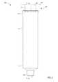
- FIG. 2is a front view of a syringe-based transfer device according to an embodiment, in a first configuration.
- FIG. 3is an exploded view of the syringe-based transfer device of FIG. 2 .
- FIG. 4is a cross-sectional view of the syringe-based transfer device illustrated in FIG. 2 taken along the line X 1 -X 1 , in the first configuration.
- FIG. 5is a cross-sectional view of the syringe-based transfer device of FIG. 2 taken along the line X 1 -X 1 , in a second configuration.
- FIG. 6is a cross-sectional view of the syringe-based transfer device of FIG. 2 taken along the line X 1 -X 1 , in a third configuration.
- FIG. 7is a front view of a syringe-based transfer device according to an embodiment, in a first configuration.
- FIG. 8is an exploded view of the syringe-based transfer device of FIG. 7 .
- FIG. 9is a cross-sectional view of the syringe-based transfer device of FIG. 7 taken along the line X 2 X 2 , in the first configuration.
- FIG. 10is a cross-sectional view of the syringe-based transfer device of FIG. 7 taken along the line X 2 -X 2 , in a second configuration.
- FIG. 11is a front view of a syringe-based transfer device according to an embodiment, in a first configuration.
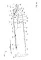
- FIG. 12is an exploded view of the syringe-based transfer device of FIG. 11 .
- FIG. 13is a cross-sectional view of the syringe-based transfer device of FIG. 11 taken along the line X 3 -X 3 , in the first configuration.
- FIG. 14is a cross-sectional view of the syringe-based transfer device of FIG. 11 taken along the line X 3 -X 3 , in a second configuration.
- FIG. 15is a cross-sectional view of the syringe-based transfer device of FIG. 11 taken along the line X 3 -X 3 , in a third configuration.
- FIG. 16is a flowchart illustrating a method of using a syringe-based transfer device to obtain a bodily fluid sample from a patient.
- a syringe-based device for parenterally-procuring bodily fluid samples with reduced contamination from a patientincludes a housing, a pre-sample reservoir, and an actuator mechanism.
- the housinghas a proximal end portion and a distal end portion and defines an inner volume therebetween.
- the proximal end portionis substantially open and the distal end portion has a port configured to be coupled to a lumen-defining device for receiving bodily fluids from the patient.
- the pre-sample reservoiris fluidically couplable to the port and is configured to receive and isolate a first volume of bodily fluid withdrawn from the patient.
- the actuator mechanismis at least partially disposed in the inner volume of the housing and has a proximal end portion and a distal end portion.
- the distal end portionincludes a sealing member and the proximal end portion includes an engagement portion configured to allow a user to selectively move the actuator mechanism between a first configuration in which the bodily fluid can flow from the port to the pre-sample reservoir, and a second configuration in which the bodily fluid can flow from the port to a sample reservoir defined at least in part by the sealing member and the housing.
- a syringe-based device for parenterally-procuring bodily fluid samples with reduced contamination from a patientincludes a housing and an actuator mechanism.
- the housinghas a proximal end portion and a distal end portion and defines an inner volume therebetween.
- the proximal end portionis substantially open and the distal end portion has a port configured to be coupled to a lumen-defining device for receiving bodily fluids from the patient.
- the actuator mechanismis movably disposed in the inner volume.
- the actuator mechanismincludes a first member having a proximal end portion and a distal end portion and defining an inner volume therebetween, and a second member movably disposed in the inner volume of the first member.
- the distal end portion of the first memberincludes a first plunger including a flow channel configured to allow selective fluid communication between the inner volume defined by the housing and the inner volume defined by the first member.
- the second memberincludes a second plunger disposed at a distal end portion of the second member and an engagement portion configured to allow a user to selectively move the actuator mechanism.
- a syringe-based device for parenterally-procuring bodily fluid samples with reduced contamination from a patientincludes a housing, an actuator mechanism, and a piercing member.
- the housinghas a proximal end portion and a distal end portion and defines an inner volume therebetween.
- the proximal end portionis substantially open and the distal end portion has a port configured to be coupled to a lumen-defining device for receiving bodily fluids from the patient.
- the actuator mechanismis movably disposed in the inner volume of the housing.
- the actuator mechanismhas a proximal end portion and a distal end portion and defining an inner volume therebetween.
- the distal end portionincludes a plunger including a flow channel.
- the proximal end portionis substantially open and configured to receive a vacuum-sealed sample tube.
- the piercing memberis disposed in the inner volume of the actuator mechanism and defines a lumen fluidically coupled to the flow channel of the plunger. The flow channel of the plunger and the piercing member configured to allow selective fluid communication between the inner volume defined by the housing and the inner volume defined by the actuator mechanism.
- a syringe-based device for parenterally-procuring bodily fluid samples with reduced contamination from a patientincludes a housing, an actuator mechanism, and a flow control mechanism.
- the housinghas a proximal end portion and a distal end portion and defines an inner volume therebetween.
- the proximal end portionis substantially open and the distal end portion has a port configured to be coupled to a lumen-defining device for receiving bodily fluids from the patient.
- the actuator mechanismis movably disposed in the inner volume of the housing and has a proximal end portion and a distal end portion.
- the distal end portionincludes a first plunger and the proximal end portion including an engagement portion configured to allow a user to selectively move the actuator mechanism.
- a second plungeris movably disposed in the inner volume of the housing and releasably coupled to the actuator mechanism.
- the second plungerdefines a flow channel configured to be placed in selective fluid communication with the port.
- the flow control mechanismis operable to selectively control fluid flow between the port and a pre-sample reservoir defined by the second plunger and the housing.
- the flow control mechanismis configured to be moved between a first configuration in which the bodily fluid can flow through a first flow path to the pre-sample reservoir, and a second configuration in which the bodily fluid can flow through a second flow path to a sample reservoir collectively defined by the first plunger, the second plunger, and the housing.
- a first volume of bodily fluidis transferred to the pre-sample reservoir with the syringe-based transfer device.
- the pre-sample reservoiris fluidically isolated from the port to sequester the first volume of bodily fluid in the pre-sample reservoir.
- fluid communicationis established between the port and a sample reservoir defined at least in part by the actuator mechanism and the housing.
- the actuator mechanismis moved from a first position to a second position to draw a second volume of bodily fluid from the patient into the sample reservoir.
- an apparatusin some embodiments, includes a housing and an actuator mechanism.
- the apparatusfurther includes a first fluid reservoir and a second fluid reservoir, fluidically isolated from the first fluid reservoir, defined at least in part by the housing and/or the actuator mechanism.
- the housingincludes a port configured to receive a bodily-fluid.
- the housing and the actuator mechanismcollectively define a first fluid flow path and a second fluid flow path.
- the first fluid flow pathis configured to transfer a first flow of bodily-fluid from the port to the first fluid reservoir when the actuator mechanism is in a first position relative to the housing.
- the second fluid flow pathis configured to transfer a second flow of bodily-fluid, substantially free from undesirable microbes that are not representative of in vivo patient condition, from the port to the second fluid reservoir when the actuator mechanism is in a second position relative to the housing.
- a bodily-fluid transfer devicecan be configured to selectively divert a first, predetermined amount of a flow of a bodily-fluid to a first reservoir before permitting the flow of a second amount of the bodily-fluid into a second reservoir.
- the second amount of bodily-fluidcan be used for diagnostic or other testing
- the first amount of bodily-fluidwhich may contain microbes from a bodily surface and/or other external source, is isolated from the bodily-fluid to be tested for microbial presence but yet can be used for other blood tests as ordered by clinician (e.g., complete blood count “CBC”, immunodiagnostic tests, cancer-cell detection tests, or the like).
- “bodily-fluid”can include any fluid obtained from a body of a patient, including, but not limited to, blood, cerebrospinal fluid, urine, bile, lymph, saliva, synovial fluid, serous fluid, pleural fluid, amniotic fluid, and the like, or any combination thereof.
- the term “set”can refer to multiple features or a singular feature with multiple parts.
- the set of wallscan be considered as one wall with distinct portions, or the set of walls can be considered as multiple walls.
- a monolithically constructed itemcan include a set of walls.
- Such a set of wallscan include, for example, multiple portions that are in discontinuous from each other.
- a set of wallscan also be fabricated from multiple items that are produced separately and are later joined together (e.g., via a weld, an adhesive or any suitable method).
- proximal and distalrefer to the direction closer to and away from, respectively, a user who would place the device into contact with a patient.
- distal endthe end of a device first touching the body of the patient
- opposite end of the devicee.g., the end of the device being manipulated by the user
- first, predetermined amountAs used in this specification and the appended claims, the terms “first, predetermined amount,” “first amount,” and “first volume” describe an amount of bodily-fluid configured to be received or contained by a first reservoir or a pre-sample reservoir. While the terms “first amount” and “first volume” do not explicitly describe a predetermined amount, it should be understood that the first amount is the first, predetermined amount unless explicitly described differently.
- second amountand “second volume” describe an amount of bodily-fluid configured to be received or contained by a second reservoir or sample reservoir.
- the second amountcan be any suitable amount of bodily-fluid and need not be predetermined.
- the second amount received and contained by the second reservoir or sample reservoircan be a second, predetermined amount.
- FIG. 1is a schematic illustration of a portion of a syringe-based transfer device 100 , according to an embodiment.
- the syringe-based transfer device 100(also referred to herein as “bodily-fluid transfer device,” “fluid transfer device,” or “transfer device”) is configured to permit the withdrawal of bodily-fluid from a patient such that a first portion or amount of the withdrawn fluid is fluidically isolated and diverted away from a second portion or amount of the withdrawn fluid that is to be used as a biological sample, such as for testing for the purpose of medical diagnosis and/or treatment.
- the transfer device 100is configured to transfer a first, predetermined amount of a bodily-fluid to a first collection reservoir and a second amount of bodily-fluid to one or more bodily-fluid collection reservoirs (e.g., sample reservoirs) fluidically isolated from the first collection reservoir, as described in more detail herein.
- a bodily-fluid collection reservoire.g., sample reservoirs
- the transfer device 100includes a housing 101 , an actuator mechanism 140 , a first fluid reservoir 180 (also referred to herein as “first reservoir” or “pre-sample reservoir”), and a second fluid reservoir 190 (also referred to herein as “second reservoir” or “sample reservoir”), different from the first reservoir 180 .
- the housing 101can be any suitable shape, size, or configuration and is described in further detail herein with respect to specific embodiments. As shown in FIG. 1 , the housing 101 includes a port 105 that can be at least temporarily physically and fluidically coupled to a medical device defining a pathway P for withdrawing and/or conveying the bodily-fluid from the patient to the transfer device 100 .
- the port 105can be a Luer-Lok® or the like configured to be physically and fluidically coupled to a needle, a cannula, or other lumen-containing device.
- the port 105can be monolithically formed with at least a portion of the lumen-containing device. In this manner, the port 105 can receive the bodily-fluid from the patient via the pathway P as further described herein.
- the housing 101defines an inner volume 111 that is configured to receive a portion of the actuator mechanism 140 . More specifically, the actuator mechanism 140 is at least partially disposed within the inner volume 111 of the housing 101 and is movable between a first configuration and a second configuration relative to the housing 101 .
- the housing 101is also configured to house at least a portion of the first reservoir 180 and at least a portion of the second reservoir 190 .
- the first reservoir 180 and/or the second reservoir 190can be at least temporarily disposed within the inner volume 111 defined by the housing 101 .
- the first reservoir 180 and/or the second reservoir 190can be at least partially defined by a set of walls of the housing 101 that define the inner volume 111 .
- a portion of the inner volume 111can form at least a portion of the first reservoir 180 and/or a portion of the second reservoir 190 .
- the actuator mechanism 140can be any suitable shape, size, or configuration.
- the shape and size of at least a portion of the actuator mechanism 140substantially corresponds to the shape and size of the walls of the housing 101 defining the inner volume 111 .
- at least a portion of the actuator mechanism 140is movably disposed within the inner volume 111 of the housing 101 .
- a distal end portion of the actuator mechanism 140is disposed within the inner volume 111 of the housing 101 and a proximal end portion of the actuator mechanism 140 is disposed substantially outside the housing 101 .
- the actuator mechanism 140can be disposed in a third configuration (or storage configuration) relative to the housing 101 , as further described herein.
- the actuator mechanism 140can include a first member and a second member. In such embodiments, both the first member and the second member can be collectively moved within the inner volume 111 of the housing 101 . In addition, the first member and the second member can be configured to move independently within the housing 101 . Similarly stated, the first member can be moved relative to the second member and/or the second member can be moved relative the first member, as further described below with respect to specific embodiments. In some embodiments, the first member and/or the second member can form a piston or plunger configured to move within the inner volume 111 . Furthermore, a portion of the piston or plunger can form a substantially fluid tight seal with the walls of the housing 101 defining the inner volume 111 .
- the housing 101 and the actuator mechanism 140can collectively form a sealed, air-tight cavity (e.g., a syringe) such that the actuator mechanism 140 (or at least a portion of the actuator mechanism 140 ) can be configured to introduce or otherwise facilitate the development of a vacuum within the inner volume 111 .
- a sealed, air-tight cavitye.g., a syringe
- the first reservoir 180can be any suitable reservoir for containing the bodily-fluid.
- the first reservoir 180is defined by a portion of the walls of the housing 101 defining the inner volume 111 and a portion of the actuator mechanism 140 .
- the first reservoir 180is defined by only the actuator mechanism 140 .
- the first reservoir 180can be a pre-sample reservoir described in detail in U.S. Pat. No. 8,197,420 (“the '420 patent”), the disclosure of which is incorporated herein by reference in its entirety.
- the first reservoir 180can be selectively placed in fluid communication with the housing 101 or the actuator mechanism 140 either directly (e.g., physically and fluidically coupled to the housing 101 or the actuator mechanism 140 ) or indirectly (e.g., fluidically coupled via intervening structure such as sterile flexible tubing).
- the first reservoir 180is configured to receive and contain the first, predetermined amount of the bodily-fluid. More specifically, when the actuator mechanism 140 is in the first configuration, a portion of the actuator mechanism 140 and a portion of the housing 101 can define a first fluid flow path 181 configured to fluidically couple the port 105 of the housing 101 to the first reservoir 180 . In some embodiments, the actuator mechanism 140 can be moved to the first configuration (e.g., from the third configuration described above) and can introduce a vacuum that facilitates the flow of the bodily-fluid through the first flow path 181 and into the first reservoir 180 .
- the first reservoir 180is configured to contain the first amount of the bodily-fluid such that the first amount is fluidically isolated from a second amount of the bodily-fluid (different than the first amount of bodily-fluid) that is subsequently withdrawn from the patient.
- the second reservoir 190can be any suitable reservoir and is configured to receive and contain the second amount of the bodily-fluid.
- the second reservoir 190is defined by a portion of the walls of the housing 101 defining the inner volume 111 and a portion of the actuator member 140 .
- a portion of the actuator mechanism 140 and a portion of the housing 101can define a second fluid flow path 191 configured to fluidically couple the port 105 to the second reservoir 190 .
- the movement of the actuator mechanism 140 to the second configurationcan be such that a second vacuum force facilitates the flow of the bodily-fluid through the second flow path 191 and into the second reservoir 190 .
- the second amount of bodily-fluidcan be an amount withdrawn from the patient subsequent to withdrawal of the first amount.
- the second reservoir 190is configured to contain the second amount of the bodily-fluid such that the second amount is fluidically isolated from the first amount of the bodily-fluid.
- the transfer device 100can be used to transfer a bodily-fluid from a patient to the first reservoir 180 and/or second reservoir 190 included in the transfer device 100 . More specifically, the flow of the first amount of bodily-fluid transferred to the first reservoir 180 can be such that dermally-residing microbes dislodged during a venipuncture event and/or other external sources (e.g. ambient airborne microbes, transferred from the skin of the practitioner collecting the sample, etc.) become entrained in the flow and are thereby transferred to the first reservoir 180 .
- dermally-residing microbes dislodged during a venipuncture event and/or other external sourcese.g. ambient airborne microbes, transferred from the skin of the practitioner collecting the sample, etc.
- the first reservoir 180fluidically isolates the first amount such that when the subsequent second amount is withdrawn into the second reservoir 190 , the second amount is substantially free from the dermally-residing microbes.
- the syringe-based transfer device 100can be coupled to a device in fluid communication with the patient that is also configured to reduce contamination of a patient sample.
- the syringe-based transfer device 100can be used with a lumenless needle or the like such as those described in U.S. Patent Application Ser. No. 61/777,758, entitled “Lumenless Needle for Bodily-Fluid Sample Collection,” filed on Mar. 12, 2013 (“the '758 application”) the disclosure of which is incorporated herein by reference in its entirety.
- the transfer device 100can be configured such that the first amount of bodily-fluid need be conveyed to the first reservoir 180 before the transfer device 100 will permit the flow of the second amount of bodily-fluid to be conveyed through the second flow path 191 to the second reservoir 180 .
- the transfer device 100can be characterized as requiring compliance by a health care practitioner regarding the collection of the first, predetermined amount (e.g., a pre-sample) prior to collection of the second amount (e.g., a sample) of bodily-fluid.
- the transfer device 100can be configured to prevent a health care practitioner from collecting the second amount, or the sample, of bodily-fluid into the second reservoir 190 without first diverting the first amount, or pre-sample, of bodily-fluid into the first reservoir 180 .
- the health care practitioneris prevented from including (whether intentionally or unintentionally) the first amount of bodily-fluid, which is more likely to contain dermally-residing microbes and/or other external undesirable contaminants, in the bodily-fluid sample to be used for analysis.
- the fluid transfer device 100need not include a forced-compliance feature or component.
- the actuator mechanism 140can have a fourth configuration, different than the first, second, and third configurations. In such embodiments, the actuator mechanism 140 can be moved towards the fourth configuration when the transfer device 100 has collected the second amount of the bodily-fluid and has been removed from contact with the patient.
- the first fluid reservoir 180can maintain the first amount of bodily-fluid in fluid isolation and the second fluid reservoir 190 can be maintained in fluid communication with the port 105 .
- the transfer device 100can transfer a portion of the second amount of the bodily-fluid from the second reservoir 190 to any suitable container (e.g., a vile, a test tube, a petri dish, a culture medium, a test apparatus, or the like) such that the portion of the second amount of bodily-fluid can be tested.
- a suitable containere.g., a vile, a test tube, a petri dish, a culture medium, a test apparatus, or the like
- FIGS. 2-6illustrate a syringe-based transfer device 200 according to an embodiment.
- the syringe-based transfer device 200(also referred to herein as “bodily-fluid transfer device,” “fluid transfer device,” or “transfer device”) includes a housing 201 and an actuator mechanism 240 .
- the transfer device 200is configured to include or define a first fluid reservoir 280 (also referred to herein as “first reservoir” or “pre-sample reservoir”) and a second fluid reservoir 290 (also referred to herein as “second reservoir” or “sample reservoir”).
- the transfer device 200can be any suitable shape, size, or configuration.
- the transfer device 200can be square, rectangular, polygonal, and/or any other non-cylindrical shape.
- the housing 201includes a proximal end portion 202 and a distal end portion 203 and defines an inner volume 211 therebetween.
- the housing 201can be substantially similar to a syringe body.
- the proximal end portion 202 of the housing 201is substantially open and is configured to receive at least a portion of the actuator mechanism 240 such that the portion of the actuator mechanism 240 is movably disposed within the inner volume 211 .
- the inner volume 211is configured to define the second fluid reservoir 290 , as further described herein.
- the distal end portion 203 of the housing 201includes a port 205 .
- the port 205can be monolithically formed with the housing 201 (e.g., as shown in FIGS. 2-6 ). In other embodiments, the port 205 can be coupled to the distal end portion 203 in any suitable manner such as, for example, via a friction fit, a threaded coupling, a mechanical fastener, an adhesive, any number of mating recesses, and/or any combination thereof.
- the port 205can be any suitable shape, size, or configuration.
- at least a portion of the port 205can form a lock mechanism configured to be physically and fluidically coupled to a needle, a cannula, or other lumen-containing device.
- the port 205can be a Luer-Lok® or similar locking mechanism configured to physically and fluidically couple to a needle or cannula assembly (not shown in FIGS. 2-6 ).
- the port 205can be monolithically formed with at least a portion of the lumen-containing device.
- the port 205can be placed in fluid communication with a lumen defined by the lumen-defining device and to receive the bodily-fluid from a patient when the lumen-defining device is disposed within the patient (e.g., as a result of a venipuncture event), as further described herein.
- the actuator mechanism 240is disposed within the inner volume 211 and is movable between a first position (e.g., a distal position relative to the housing 201 ) and a second position (e.g., a proximal position relative to the housing 201 ). Furthermore, the movement of the actuator mechanism 240 relative to the housing 201 can move the transfer device 200 between a first, second, and third configuration, as further described herein.
- the actuator mechanism 240includes a first member 241 and a second member 251 .
- the first member 241 of the actuator mechanism 240includes a proximal end portion 242 and a distal end portion 243 and defines an inner volume 246 therebetween. At least a portion of the inner volume 246 is configured to define the first reservoir 280 , as further described herein.
- the proximal end portion 242is substantially open such that at least a portion of the second member 251 can be movably disposed within the inner volume 246 .
- the proximal end portion 242also includes a protrusion 244 that extends from an inner surface of a wall (or set of walls) defining the inner volume 246 and is configured to selectively engage a portion of the second member 251 .
- the distal end portion 243 of the first member 241includes a plunger 247 .
- the plunger 247is configured to form a friction fit with the inner surface of the walls defining the inner volume 211 when the actuator mechanism 240 is disposed within the housing 201 .
- the plunger 247defines a fluidic seal with the inner surface of the walls defining the inner volume 211 such that a portion of the inner volume 211 proximal of the plunger 247 is fluidically isolated from a portion of the inner volume 211 distal of the plunger 247 .
- the plunger 247is further configured to define a channel 248 that extends though a distal end and a proximal end of the plunger 247 .
- a portion of an inner set of walls defining the channel 248is configured to form a valve seat 249 . In this manner, a portion of the channel 248 can receive a valve 270 that is in contact with the valve seat 249 .
- the valve 270can be any suitable valve.
- the valve 270is a one-way check valve configured to allow a flow of a fluid from a distal end of the valve 270 to a proximal end of the valve 270 but substantially not allow a flow of the fluid from the proximal end to the distal end.
- the valve 270can be disposed within the channel 248 and can be in contact with the valve seat 249 such that the valve 270 forms a substantially fluid tight seal with the walls defining the channel 248 .
- the valve 270can form a first fit with walls defining the channel 248 .
- the valve 270can form a threaded coupling or the like with at least a portion of the walls.
- the valve 270can also include a seal member configured to engage the valve seat 249 thereby forming at least a portion of the fluid tight seal.
- the arrangement of the plunger 247 and the valve 270is such that when the valve 270 is in the open configuration, the inner volume 246 defined by the first member 241 is placed in fluid communication with the portion of the inner volume 211 of the housing 201 that is distal of the plunger 247 , as further described herein.
- the second member 251 of the actuator mechanism 240includes a proximal end portion 252 and a distal end portion 253 .
- the proximal end portion 252includes an engagement portion 258 that can be engaged by a user (e.g., a phlebotomist, a nurse, a technician, a physician, etc.) to move at least a portion of the actuator mechanism 240 relative to the housing 201 .
- the distal end portion 253includes a plunger 257 configured to form a friction fit with the inner surface of the walls defining the inner volume 246 when the second member 251 is disposed with the first member 241 .
- the plunger 257defines a fluidic seal with the inner surface of the walls defining the inner volume 246 such that a portion of the inner volume 246 proximal of the plunger 257 is fluidically isolated from a portion of the inner volume 246 distal of the plunger 257 .
- the second member 251is configured to be movably disposed within the inner volume 246 of the first member 241 . More specifically, the second member 251 can be movable between a first position (e.g., a distal position) and a second position (e.g., a proximal position) thereby moving the actuator mechanism 240 between a first configuration and a second configuration, respectively.
- the second member 251includes a protrusion 254 that extends in a radial direction to selectively engage the protrusion 244 of the first member 241 . In this manner, the protrusion 244 of the first member 241 and the protrusion 254 of the second member 251 can be placed in contact to substantially limit a proximal movement of the second member 251 relative the first member 241 .
- a usercan engage the transfer device 200 to couple the port 205 to a proximal end portion of a lumen-defining device (not shown) such as, for example, a butterfly needle, a cannula assembly, a trocar (which is some cases is used to insert a catheter into a patient), or the like.
- a lumen-defining devicesuch as, for example, a butterfly needle, a cannula assembly, a trocar (which is some cases is used to insert a catheter into a patient), or the like.
- the port 205With the port 205 physically coupled to the lumen-defining device, the port 205 is placed in fluid communication with the lumen defined by the lumen-defining device.
- the distal end portion of the lumen-defining devicecan be disposed within a portion of the body of a patient (e.g., a vein). In this manner, the port 205 is placed in fluid communication with the portion of the body.
- a usere.g., a phlebotomist, a nurse, a technician, a physician, or the like
- the transfer device 200can move from the first configuration to the second configuration. More specifically, the user can engage the engagement portion 258 of the second member 251 included in the actuator mechanism 240 to move the actuator mechanism 240 from its first configuration to its second configuration, thereby placing the transfer device 200 in the second configuration, as indicated by the arrow AA in FIG. 5 .
- the second member 251 of the actuator mechanism 240is moved in a proximal direction relative to the first member 241 (e.g., the first member 241 does not substantially move in the proximal direction) until the protrusion 254 of the second member 251 is placed into contact with the protrusion 244 of the first member 241 .
- the arrangement of the second member 251 within the first member 241is such that the proximal motion of the second member 251 increases the volume of the portion of the inner volume 246 that is distal of the plunger 257 , thereby defining the first reservoir 280 . Furthermore, with the plunger 257 forming a fluid tight seal with the inner surface of the walls defining the inner volume 246 , the increase of volume can produce a negative pressure within the first reservoir 280 .
- the port 205 , the valve 270 , and the channel 248define a fluid flow path that places the first reservoir 280 in fluid communication with the lumen-defining device. Therefore, the first reservoir 280 is placed in fluid communication with the portion of the patient (e.g., the vein). Expanding further, the negative pressure within the first reservoir 280 can be operative in moving the valve 270 from a closed configuration to an open configuration. In this manner, the negative pressure within the within the first reservoir 280 produced by the movement of the plunger 257 introduces a suction force within the portion of the patient. Thus, a bodily-fluid is drawn through the port 205 and the valve 270 and into the first reservoir 280 . In some embodiments, the bodily-fluid can contain undesirable microbes such as, for example, dermally-residing microbes and/or other external contaminants.
- the magnitude of the suction forcecan be modulated by increasing or decreasing the amount of a force applied to the actuation mechanism 240 .
- itcan be desirable to limit the amount of suction force introduced to a vein.
- the usercan reduce the amount of force applied to the engagement portion 258 of the second member 251 .
- the rate of changee.g., the increase
- the volume of the first reservoir 280can be sufficiently slow to allow time for the negative pressure differential between the vein and the fluid reservoir to come to equilibrium before further increasing the volume of the first reservoir 280 .
- the magnitude of the suction forcecan be modulated.
- the transfer device 200can be configured to transfer a desired amount (e.g., a predetermined amount) of bodily-fluid transferred to the first reservoir 280 .
- a desired amounte.g., a predetermined amount
- the first, predetermined amountcan substantially correspond to the size of the first reservoir 280 .
- the first amountcan substantially correspond to an equalization of pressure within the first reservoir 280 and the portion of the patient.
- the equalization of the pressurecan be such that the valve 270 is allowed to return to the closed configuration.
- the first reservoir 280is fluidically isolated from a volume substantially outside the first reservoir 280 .
- the actuator mechanism 240can be moved from the second configuration to a third configuration by further moving the actuator mechanism 240 in the proximal direction.
- the usercan apply a force to the engagement portion 258 of the second member 251 to move the actuator mechanism 240 relative to the housing 201 .
- the further application of force on the engagement portion 258is such that the first member 241 and the second member 251 collectively move in the proximal direction relative to the housing 201 .
- the arrangement of the first member 241 within the inner volume 211 of the housing 201is such that the proximal motion of the first member 241 increases the volume of the portion of the inner volume 211 that is distal of the plunger 247 , thereby defining the second reservoir 290 . Furthermore, with the plunger 247 forming a fluid tight seal with the inner surface of the walls defining the inner volume 211 and with the valve 270 in the closed configuration, the increase of volume can produce a negative pressure within the second reservoir 290 .
- the port 205 and a portion of the inner volume 211define a fluid flow path that places the second reservoir 290 in fluid communication with the lumen-defining device. Therefore, the second reservoir 290 is placed in fluid communication with the portion of the patient (e.g., the vein). Expanding further, the negative pressure within the second reservoir 290 produced by the movement of the plunger 247 introduces a suction force within the portion of the patient. Thus, a bodily-fluid is drawn through the port 205 and into the second reservoir 290 .
- the bodily-fluid contained within the second reservoir 290is substantially free from microbes generally found outside of the portion of the patient (e.g., dermally residing microbes, microbes within a lumen defined by the transfer device 200 , microbes within the lumen defined by the lumen defining device, and/or any other undesirable microbe).
- the actuator mechanism 240can be moved from the third configuration to a fourth configuration to place the transfer device 200 in a fourth configuration.
- the transfer device 200can be removed from the portion of the patient and disposed above or in a container (e.g., a vile, a test tube, a petri dish, a culture medium, a test apparatus, a cartridge designed for use with an automated, rapid microbial detection system, or the like) such that at least a portion of the second amount of bodily-fluid can be tested.
- a containere.g., a vile, a test tube, a petri dish, a culture medium, a test apparatus, a cartridge designed for use with an automated, rapid microbial detection system, or the like
- the withdrawn bodily-fluidcan be used for any number of testing processes or procedures such as, for example, blood culture testing, real-time diagnostics, and/or PCR-based approaches. Expanding further, the user can apply a force to the engagement portion 258 of the second member 251 to move the actuator mechanism 240 in the distal direction (e.g., opposite the arrow CC shown in FIG. 6 ). With the valve 270 in the closed configuration the bodily-fluid contained within the first reservoir 280 is maintained in fluid isolation with a volume outside the first reservoir 280 . In some embodiments, the volume of the first reservoir 280 is sufficient to contain the first centiliter or few centiliters of bodily-fluid.
- the first reservoir 280can be configured to contain from about 0.1 ml to about 3.0 ml. In still other embodiments, the first reservoir 280 can be configured to contain from about 3.0 ml, 4.0 ml, 5.0 ml, 6.0 ml, 7.0 ml, 8.0 ml, 9.0 ml, 10.0 ml, 15.0 ml, 20.0 ml, 25.0 ml, 50 ml, or any volume or fraction of volume therebetween. Furthermore, the pressure within the first reservoir 280 can be such that the force applied to the second member 251 does not substantially move the second member 251 relative to the first member 241 .
- the force applied to the engagement portion 258collectively moves the second member 251 and the first member 241 in the distal direction relative to the housing 201 to expel a desired portion of the second amount of bodily-fluid from the lumen-defining device and into the container.
- the syringe-based transfer device 200can be coupled to a device in fluid communication with the patient that is also configured to reduce contamination of a patient sample.
- the syringe-based transfer device 200can be used with a lumenless needle or the like such as those described in the '758 application.
- FIGS. 7-10illustrate a syringe-based transfer device 300 according to an embodiment.
- the syringe-based transfer device 300(also referred to herein as “bodily-fluid transfer device,” “fluid transfer device,” or “transfer device”) is configured to be moved between a first, second, third, and fourth configuration, as further described herein.
- the transfer device 300includes a housing 301 and an actuator 341 .
- the transfer device 300is configured to include or define a first fluid reservoir 380 (also referred to herein as “first reservoir” or “pre-sample reservoir”) and a second fluid reservoir 390 (also referred to herein as “second reservoir” or “sample reservoir”).
- the transfer device 300can be any suitable shape, size, or configuration.
- the transfer device 300can be square, rectangular, polygonal, and/or any other non-cylindrical shape. Moreover, portions of the transfer device 300 can be substantially similar to the corresponding portions of the transfer device 200 , described above in reference to FIGS. 2-6 . Therefore, such portions are not described in further detail herein and should be considered substantially similar unless explicitly described differently.
- the housing 301includes a proximal end portion 302 and a distal end portion 303 and defines an inner volume 311 therebetween.
- the proximal end portion 302 of the housing 301is substantially open and is configured to receive at least a portion of the actuator 341 such that the portion of the actuator 341 is movably disposed within the inner volume 311 .
- the inner volume 311is configured to define the second fluid reservoir 390 , as further described herein.
- the distal end portion 303 of the housing 301includes a port 305 .
- the port 305is configured to be coupled to or monolithically formed with a lumen-containing device, such as those described above.
- the actuator 341is disposed within the inner volume 311 and is movable between a first position (e.g., a distal position relative to the housing 301 ) and a second position (e.g., a proximal position relative to the housing 301 ).
- the actuator 341includes a proximal end portion 342 and a distal end portion 343 and defines an inner volume 346 therebetween.
- the proximal end portion 342includes an engagement portion 350 , as described above with respect to the second member 251 of the actuator mechanism 240 .
- the proximal end 342is substantially open such that at least a portion of the first reservoir 380 can be movably disposed within the inner volume 346 .
- the distal end portion 343 of the actuator 341includes a plunger 347 .
- the plunger 347is configured to form a friction fit with the inner surface of the walls defining the inner volume 311 when the actuator 341 is disposed within the housing 301 , as described in detail above in reference FIGS. 2-6 .
- the plunger 347also defines a channel 348 that extends though a distal end and a proximal end of the plunger 347 .
- the channel 348is configured to receive a port 375 having a base 376 and a piercing member 377 .
- the base 376can be disposed within the channel 348 and forms a friction fit with a set walls defining the channel 348 .
- the piercing member 377 of the port 375is configured to extend in the proximal direction from the base 376 . As shown in FIG. 8 , the piercing member 377 can be disposed within a sheath configured to be selectively moved to expose, for example, a needle. For simplicity, FIGS. 8-10 only illustrate a sheath of the piercing member and not the needle disposed therein.
- a portion of the set of walls defining the channel 348is configured to form a valve seat 349 .
- a portion of the channel 348can receive a valve 370 such that the valve 370 is in contact with the valve seat 349 .
- the valve 370can be any suitable configuration, for example, the valve 370 can be similar in form and function to the valve 270 described above.
- the arrangement of the plunger 347 and the valve 370is such that when the valve 370 is in the open configuration, the port 375 is placed in fluid communication with the portion of the inner volume 311 of the housing 301 that is distal of the plunger 347 , as further described herein.
- a usercan engage the transfer device 300 to couple the port 305 to a proximal end portion of a lumen-defining device (not shown) such as, for example, a butterfly needle, a cannula assembly, a trocar (which in some cases is used to insert a catheter into a patient), or the like.
- a lumen-defining devicesuch as, for example, a butterfly needle, a cannula assembly, a trocar (which in some cases is used to insert a catheter into a patient), or the like.
- the port 305With the port 305 physically coupled to the lumen-defining device, the port 305 is placed in fluid communication with the lumen defined by the lumen-defining device.
- the distal end portion of the lumen-defining devicecan be disposed within a portion of the body of a patient (e.g., a vein). In this manner, the port 305 is placed in fluid communication with the portion of the body.
- a usere.g., a phlebotomist, a nurse, a technician, a physician, or the like
- the transfer device 300can move from the first configuration to the second configuration.
- the usercan engage the first reservoir 380 and place the first reservoir 380 within the inner volume 346 defined by the actuator 341 .
- the first reservoir 380can be an external fluid reservoir configured to receive a fluid.
- the first reservoir 380can be a Vacutainer® and/or a monolithically formed chamber in the transfer device 300 with or without a negative pressure.
- the first reservoir 380can be a pre-sample reservoir such as those disclosed in the '420 patent. In this manner, the first reservoir 380 can be placed within the inner volume 346 of the actuator 341 , as indicated by the arrow EE in FIG. 9 .
- the insertion of the first reservoir 380 into the inner volume 346 of the actuator 341can place the transfer device 300 in the second configuration.
- the distal end portion of the first reservoir 380can be configured to include a pierceable septum that can receive the piercing member 377 of the port 375 . While not shown in FIG. 9 , the distal end portion of the first reservoir 380 can engage the port 375 such that the sheath of the piercing member 377 is moved, thereby exposing the needle. Thus, the needle can pierce the septum of the first reservoir 380 to place the first reservoir 380 in fluid communication with the port 375 .
- the arrangement of the first reservoir 380can also be such that the inner volume defined therein is substantially evacuated. Similarly stated, the inner volume of the first reservoir 380 defines a negative pressure.
- the port 305 , the valve 370 , and the port 375define a fluid flow path such that the first reservoir 380 is in fluid communication with the lumen-defining device. Therefore, the first reservoir 380 is placed in fluid communication with the portion of the patient (e.g., the vein, the spinal cavity, etc.). Expanding further, the negative pressure within the first reservoir 380 can be operative in moving the valve 370 from a closed configuration to an open configuration. In this manner, the negative pressure within the within the first reservoir 380 introduces a suction force within the portion of the patient. Thus, a bodily-fluid is drawn through the port 305 , the valve 370 , and the port 375 and into the first reservoir 380 . In some embodiments, the bodily-fluid can contain undesirable microbes such as, for example, dermally-residing microbes and/or other external contaminants.
- the transfer device 300can be configured to transfer a desired amount (e.g., a predetermined amount) of bodily-fluid transferred to the first reservoir 380 .
- a desired amounte.g., a predetermined amount
- the first, predetermined amountcan substantially correspond to an equalization of pressure within the first reservoir 380 and the portion of the patient.
- the equalization the pressurecan be such that the valve 370 is allowed to return to the closed configuration.
- the first reservoir 380is fluidically isolated from a volume substantially outside the first reservoir 380 .
- the first reservoir 380can be removed from the inner volume 346 of the actuator 341 and discarded.
- the actuator 341can be moved from the second configuration to a third configuration by moving the actuator 341 in the proximal direction.
- the usercan apply a force to the engagement portion 350 of the actuator 341 to move the actuator 341 relative to the housing 301 .
- the arrangement of the actuator 341 within the inner volume 311 of the housing 301is such that the proximal motion of the actuator 341 increases the volume of the portion of the inner volume 311 that is distal of the plunger 347 , thereby defining the second reservoir 390 . Furthermore, with the plunger 347 forming a fluid tight seal with the inner surface of the walls defining the inner volume 311 and with the valve 370 in the closed configuration, the increase of volume can produce a negative pressure within the second reservoir 390 .
- the port 305 and a portion of the inner volume 311define a fluid flow path such that the second reservoir 390 is in fluid communication with the lumen-defining device. Therefore, the second reservoir 380 is placed in fluid communication with the portion of the patient (e.g., the vein, spinal cavity, etc.). Expanding further, the negative pressure within the second reservoir 390 produced by the movement of the plunger 347 introduces a suction force within the portion of the patient. Thus, a bodily-fluid is drawn through the port 305 and into the second reservoir 390 .
- the bodily-fluid contained within the second reservoir 390is substantially free from microbes generally found outside of the portion of the patient (e.g., dermally residing microbes, microbes within a lumen defined by the transfer device 300 , microbes within the lumen defined by the lumen defining device, and/or any other undesirable microbe).
- the syringe-based transfer device 300can be coupled to a device in fluid communication with the patient that is also configured to reduce contamination of a patient sample.
- the syringe-based transfer device 300can be used with a lumenless needle or the like such as those described in the '758 application.
- the actuator 341can be moved from the third configuration to a fourth configuration to place the transfer device 300 in a fourth configuration.
- the transfer device 300can be removed from the portion of the patient and disposed above or in a container (e.g., a vile, a test tube, a petri dish, a culture medium, a test apparatus, a cartridge or the like) such that a portion of the second amount of bodily-fluid can be tested.
- a containere.g., a vile, a test tube, a petri dish, a culture medium, a test apparatus, a cartridge or the like
- the usercan apply a force to the engagement portion 350 to move the actuator 341 in the distal direction.
- valve 370in the closed configuration the force applied to the engagement portion 350 the actuator 341 in the distal direction relative to the housing 301 to expel a desired portion of the second amount of bodily-fluid from the lumen-defining device and into the container.
- a transfer devicecan include a flow control mechanism configured to direct a flow of the bodily-fluid.
- FIGS. 11-15illustrate a syringe-based transfer device 400 according to an embodiment.
- the syringe-based transfer device 400(also referred to herein as “bodily-fluid transfer device,” “fluid transfer device,” or “transfer device”) includes a housing 401 , a flow control mechanism 430 , and an actuator mechanism 440 .
- the transfer device 400is configured to include or define a first fluid reservoir 480 (also referred to herein as “first reservoir” or “pre-sample reservoir”) and a second fluid reservoir 490 (also referred to herein as “second reservoir” or “sample reservoir”).
- the transfer device 400can be any suitable shape, size, or configuration. For example, while shown in FIGS. 11 and 12 as being substantially cylindrical, the transfer device 400 can be square, rectangular, polygonal, and/or any other non-cylindrical shape.
- portions of the transfer device 400can be substantially similar to the corresponding portions of the transfer device 200 , described above in reference to FIGS. 2-6 . Therefore, such portions are not described in further detail herein and should be considered substantially similar unless explicitly described differently.
- the housing 401includes a proximal end portion 402 , a distal end portion 403 , and defines an inner volume 411 therebetween.
- the proximal end portion 402 of the housing 401is substantially open and is configured to receive at least a portion of the actuator mechanism 440 such that the portion of the actuator mechanism 440 is movably disposed within the inner volume 411 .
- the inner volume 411is configured to define, at least partially, the first fluid reservoir 480 the second fluid reservoir 490 , as further described herein.
- the distal end portion 403 of the housing 401includes a port 405 and a diverter 409 .
- the port 405is configured to be coupled to or monolithically formed with a lumen-containing device, such as those described above.
- the diverter 409defines a void 408 that movably receives a portion of the flow control mechanism 430 . As shown in FIG. 13 , the void 408 is in fluid communication with the port 405 .
- the diverter 409further defines a first lumen 406 in fluid communication with the void 408 and a first portion of the inner volume 411 , and a second lumen 407 in fluid communication with the void 408 and a second portion of the inner volume 411 . In this manner, the diverter 409 can selectively receive a flow of a bodily-fluid as further described herein.
- the flow control mechanism 430includes a first member 431 and a second member 435 . As described above, at least a portion of the flow control mechanism 430 is movably disposed within a portion of the housing 401 . More specifically the first member 431 is rotatably disposed within the void 408 of the diverter 409 . The first member 431 defines a first lumen 432 and a second lumen 433 and defines a circular cross-sectional shape. In this manner, the first member 431 can be disposed within the void 408 such that a portion of the first member 431 forms a friction fit with the walls of the diverter 409 defining the void 408 .
- the first member 431is formed from silicone and has a diameter larger than the diameter of the void 408 . In this manner, the diameter of the first member 431 is reduced when the first member 431 is disposed within the void 408 .
- the outer surface of the first member 431forms a friction fit with the inner surface of the walls defining the void 408 .
- the first member 431can be any suitable elastomer configured to deform when disposed within the void 408 of the diverter 409 .
- the second member 435is disposed substantially outside the void 408 and can be engaged by a user to rotate the flow control mechanism 430 between a first configuration and a second configuration.
- the first member 431can be coupled to and/or otherwise engage the second member 445 .
- the second member 435can be coupled to the first member 431 via a mechanical fastener and/or adhesive.
- the second member 435 and the first member 431can be coupled in any suitable manner. Therefore, the first member 431 is configured to move concurrently with the second member 435 when the second member 435 is rotated relative to the housing 401 .
- the flow control mechanism 430can be rotated to place the first lumen 432 or the second lumen 433 in fluid communication with the port 405 , the first lumen 406 , and/or the second lumen 407 , as described in further detail herein.
- the actuator mechanism 440is disposed within the inner volume 411 and is movable between a first position (e.g., a distal position relative to the housing 401 ) and a second position (e.g., a proximal position relative to the housing 401 ). Furthermore, the movement of the actuator mechanism 440 relative to the housing 401 can move the transfer device 400 between a first, second, and third configuration, as further described herein.
- the actuator mechanism 440includes a first member 470 and a second member 451 .
- the first member 470includes a shunt tube 471 and a plunger 476 .
- the plunger 476defines a channel 477 is configured to be movably disposed about the shunt tube 471 .
- the shunt tube 471is disposed within the channel 477 .
- the plunger 476can be substantially similar in function to those described in detail above.
- the plunger 476can be configured to form a friction fit with a set of walls that define the inner volume 411 of the housing 401 . In this manner, the plunger 476 and the walls defining the inner volume 411 form a substantially fluid tight seal.
- the plunger 476 and the shunt tube 471form a substantially fluid tight seal. Therefore, the plunger 476 fluidically isolates a portion of the inner volume 411 proximal of the plunger 476 from a portion of the inner volume 411 distal of the plunger 476 .
- the shunt tube 471includes a proximal end portion 472 and a distal end portion 473 .
- the distal end portion 473is coupled to a portion of the diverter 409 such that a lumen 475 defined by the shunt tube 471 is in fluid communication with the second lumen 407 defined by the diverter 409 .
- the proximal end portion 472 of the shunt tube 471includes a protrusion 474 that is configured to engage the plunger 476 to substantially limit a proximal movement of the plunger 476 relative to the shunt tube 471 , as further described herein.
- the second member 451 of the actuator mechanism 440includes a proximal end portion 452 and a distal end portion 453 .
- the proximal end portion 452includes an engagement portion 458 that can be engaged by a user (e.g., a phlebotomist, a nurse, a technician, a physician, etc.) to move at least a portion of the actuator mechanism 440 relative to the housing 401 .
- the distal end portion 453includes a plunger 457 configured to form a friction fit with the inner surface of the walls defining the inner volume 446 when the second member 451 is disposed with the inner volume 411 .
- the plunger 457defines a fluidic seal with the inner surface of the walls defining the inner volume 411 such that a portion of the inner volume 411 proximal of the plunger 457 is fluidically isolated from a portion of the inner volume 411 distal of the plunger 457 .
- the second member 451can be at least temporarily coupled to the plunger 476 of the first member 470 .
- the plunger 457 of the second member 451can include a protrusion configured to be disposed within a groove defined by the plunger 476 of the first member 470 .
- the first member 470 and the second member 451can be configured to collectively move, at least temporarily, within the housing 401 , and can further be configured to move, at least temporarily, relative to each other.
- the distal end portion 453defines a channel 459 configured to be selectively disposed about a portion of the shunt tube 471 .
- the channel 459can be configured to have a diameter that is sufficiently large such that the second member 451 can freely move about the shunt tube 471 (e.g., the shunt tube 471 and the walls defining the channel do not form a substantial friction fit.
- a usercan engage the transfer device 400 to couple the port 405 to a proximal end portion of a lumen-defining device (not shown) such as, for example, a butterfly needle, a cannula assembly, a trocar (which in some cases is used to insert a catheter into a patient), or the like.
- a lumen-defining devicesuch as, for example, a butterfly needle, a cannula assembly, a trocar (which in some cases is used to insert a catheter into a patient), or the like.
- the port 405With the port 405 physically coupled to the lumen-defining device, the port 405 is placed in fluid communication with the lumen defined by the lumen-defining device.
- the distal end portion of the lumen-defining devicecan be disposed within a portion of the body of a patient (e.g., a vein, spinal column, etc.). In this manner, the port 405 is placed in fluid communication with the portion of the body.
- a usere.g., a phlebotomist, a nurse, a technician, a physician, or the like
- the transfer device 400can move from the first configuration to the second configuration. More specifically, the user can engage the engagement portion 458 of the second member 451 included in the actuator mechanism 440 to move the actuator mechanism 440 from its first configuration to its second configuration, thereby placing the transfer device 400 in the second configuration, as indicated by the arrow II in FIG. 14 . In this manner, the actuator mechanism 440 is moved in a proximal direction relative to the housing 401
- the arrangement of the actuator mechanism 440is such that the proximal motion of the second member 451 moves the plunger 476 of the first member 470 in the proximal direction relative to the shunt tube 471 .
- the first member 470can be at least temporarily coupled to the second member 451 such that the first member 470 and the second member 451 move concurrently in the proximal direction relative to the housing 401 . In this manner, the first member 470 moves in the proximal direction until the first member 470 is placed in contact with the protrusion 474 included in the shunt tube 471 .
- the proximal movement of the plunger 476increases the volume of the portion of the inner volume 411 of the housing 401 that is distal of the plunger 476 , thereby defining the first reservoir 480 , as shown in FIG. 14 .
- the volume increase of the portion of the inner volume 411can produce a negative pressure within the first reservoir 480 .
- first member 431 of the flow control mechanism 430can be disposed within the void 408 such that the first lumen 432 defined by the flow control mechanism 430 is in fluid communication with the port 405 and in fluid communication with the first lumen 406 defined by the diverter 409 .
- the port 405 , the first lumen 432 defined by the flow control mechanism 430 , and the first lumen 406 defined by the diverter 409define a fluid flow path that places the first reservoir 480 in fluid communication with the lumen-defining device, as indicated by the arrow JJ in FIG. 14 .
- the first reservoir 480is placed in fluid communication with the portion of the patient (e.g., the vein). Expanding further, the negative pressure within the first reservoir 480 produced by the movement of the plunger 476 (as indicated by the arrow II) introduces a suction force within the portion of the patient. Thus, a bodily-fluid is drawn through the port 405 , the first lumen 432 defined by the flow control mechanism 430 , and the first lumen 406 defined by the diverter 409 and into the fluid reservoir 480 .
- the bodily-fluidcan contain undesirable microbes such as, for example, dermally-residing microbes and/or other external contaminants.
- the magnitude of the suction forcecan be modulated by moving the rotating the flow control mechanism 430 relative to the diverter 409 .
- the rotation of the flow control mechanism 330reduces the size of the fluid pathway (e.g., an inner diameter) between the port 405 and the first lumen 432 of the flow control mechanism 430 and the first lumen 406 of the diverter 409 and the first lumen 432 of the flow control mechanism 430 , thereby reducing the suction force introduced into the vein of the patient.
- the desired amount of bodily-fluid transferred to the first reservoir 480is a predetermined amount of fluid (as described above).
- the volume of the first reservoir 480is sufficient to contain the first centiliter or few centiliters of bodily-fluid.
- the first reservoir 480can be configured to contain from about 0.1 ml to about 3.0 ml.
- the first reservoir 480can be configured to contain from about 3.0 ml, 4.0 ml, 5.0 ml, 6.0 ml, 7.0 ml, 8.0 ml, 9.0 ml, 10.0 ml, 15.0 ml, 20.0 ml, 25.0 ml, 50 ml, or any volume or fraction of volume therebetween.
- the predetermined amount of bodily-fluide.g., volume
- the flow control mechanism 430can be configured to automatically move from the first configuration to the second configuration to divert fluid flow without user intervention.
- the transfer device 400can be moved from the second configuration to the third configuration by rotating the second member 435 of the flow control mechanism 430 relative to the diverter 409 , as indicated by the arrow KK.
- the flow control mechanism 430is moved to the second configuration, and the first lumen 432 is fluidically isolated from the port 405 and the first lumen 406 of the diverter 409 .
- the first reservoir 480is fluidically isolated from a volume substantially outside the first reservoir 480 .
- the second lumen 433 defined by the flow control mechanism 430is placed in fluid communication with the port 405 and the second lumen 407 defined by the diverter 409 .
- the port 405 , the second lumen 433 of the flow control mechanism 430 , the second lumen 407 of the diverter 409 , and the lumen 475 of the shunt tube 471define a fluid flow path, as indicated by the arrow LL.
- the second member 451 of the actuator mechanism 440can be moved from the second configuration to a third configuration. Expanding further, with the plunger 476 in contact with the protrusion 474 of the shunt 471 , the second member 451 can be moved in the proximal direction to decouple the second member 451 from the plunger 476 (as described above the plunger 476 is at least temporarily coupled to the first member 451 ). In this manner, the second member 451 can be moved in the proximal direction relative to the first member 470 , as indicated by the arrow MM in FIG. 15 .
- the proximal movement of the second member 451 relative to the first member 470increases the volume of the portion of the inner volume 411 that is proximal of the plunger 476 of the first member 470 and distal of the plunger 457 of the second member 451 , thereby defining the second reservoir 490 .
- the volume increase of the portion of the inner volume 411can produce a negative pressure within the first reservoir 490 .
- the negative pressure within the second reservoir 490is such that the negative pressure differential between the second reservoir 490 and the portion of the body of the patient introduces a suction force within the portion of the patient.
- a desired amount of bodily-fluidis drawn through the port 405 , the second lumen 433 of the flow control mechanism 430 , the second lumen 407 of the diverter 409 , and the lumen 475 defined by the shunt tube 471 and into the second reservoir 490 .
- the bodily-fluid disposed within the second reservoir 490is fluidically isolated from the first, predetermined amount of bodily-fluid contained within the first reservoir 480 .
- the syringe-based transfer device 400can be coupled to a device in fluid communication with the patient that is also configured to reduce contamination of a patient sample.
- the syringe-based transfer device 400can be used with a lumenless needle or the like such as those described in the '758 application.
- the actuator mechanism 440can be moved from the third configuration to a fourth configuration to place the transfer device 400 in a fourth configuration.
- the transfer device 400can be removed from the portion of the patient and disposed above or in a container (e.g., a vile, a test tube, a petri dish, a culture medium, a test apparatus, or the like) such that a portion of the second amount of bodily-fluid can be tested.
- a containere.g., a vile, a test tube, a petri dish, a culture medium, a test apparatus, or the like
- the usercan apply a force to the engagement portion 458 to move the second member 451 in the distal direction. Therefore, the force applied to the engagement portion 458 moves the second member 451 in the distal direction relative to the housing 301 to expel a desired portion of the second amount of bodily-fluid from the lumen-defining device and into the container.
- FIG. 16is a flowchart illustrating a method 1000 of using a syringe-based transfer device to obtain a bodily fluid sample from a patient.
- the syringe-based transfer devicecan be any suitable device such as those described herein.
- the syringe-based transfer devicecan include a housing having a port configured to be coupled to the patient, and an actuator mechanism movably disposed in the housing.
- the housing, the port, and the actuator mechanismcan be substantially similar to or the same as the housing 201 , the port 205 , and the actuator mechanism 240 , respectively, described above with reference to FIGS. 2-6 .
- the method 1000includes establishing fluid communication between the patient and the port of the syringe-based transfer device, at 1001 .
- the portcan be coupled to a proximal end portion of a lumen-defining device such as, for example, a butterfly needle, a cannula assembly, or the like that is in fluid communication with the patient (e.g., at least a distal end portion of the lumen-defining device is disposed in the body of the patient).
- a lumen-defining devicesuch as, for example, a butterfly needle, a cannula assembly, or the like that is in fluid communication with the patient (e.g., at least a distal end portion of the lumen-defining device is disposed in the body of the patient).
- a usercan establish fluid communication between the port and a pre-sample reservoir included in and/or defined by the syringe-based transfer device, at 1002 .
- the usercan move the actuator mechanism from a first configuration to a second configuration, thereby placing the port in fluid communication with the pre-sample reservoir.
- the movement of the actuator mechanismcan increase an inner volume which, in turn, can produce a negative pressure within the pre-sample reservoir, as described above with reference to the transfer device 200 in FIG. 5 .
- the syringe-based transfer devicecan be manipulated to modulate the magnitude of suction force by controlling the movement of the actuator mechanism.
- a first volume of bodily-fluidis transferred to the pre-sample reservoir with the syringe-based transfer device, at 1003 .
- the bodily-fluidcan contain undesirable microbes such as, for example, dermally-residing microbes and/or other external contaminants.
- the first volume of bodily-fluidcan be any suitable volume.
- the first volume of bodily-fluid transferred to the pre-sample reservoircan be a predetermined volume.
- the first volumecan be, for example, about 0.1 ml, about 0.3 ml, about 0.5 ml, about 1.0 ml, about 2.0 ml, about 3.0 ml, about 4.0 ml, about 5.0 ml, about 10.0 ml, about 20 ml, about 50 ml, and/or any volume or fraction of a volume therebetween.
- the first volumecan be greater than 50 ml or less than 0.1 ml.
- the first volumecan substantially correspond to the size of the pre-sample reservoir 280 .
- the pre-sample reservoiris fluidically isolated from the port to sequester the first volume of bodily-fluid in the pre-sample reservoir, at 1004 .
- the usercan move the actuator mechanism and/or otherwise manipulate the syringe-based transfer device to fluidically isolate the pre-sample reservoir.
- the housingcan define an inner volume in which the actuator mechanism is at least partially disposed.
- the actuator mechanismcan include a seal member or plunger that can form a substantially fluid tight seal with a set of walls defining the inner volume of the housing, thereby defining the sample reservoir.
- the actuator mechanism and the housingcan define the sample reservoir in a similar manner as described above with reference to the actuator mechanism 240 , the housing 201 , and the sample reservoir 290 of FIG. 6 .
- the actuator mechanismcan be moved from a first position to a second position to draw a second volume of bodily-fluid from the patient into the sample reservoir, at 1006 .
- the second volume of bodily-fluid transferred to the sample reservoircan be substantially free from contaminants such as, for example, dermally residing microbes or the like.
- a flow control mechanismcan be rotated in a first direction (e.g., in the direction of the arrow KK in FIG. 15 ) and a second direction, opposite the first.
- the rotation in the second directioncan be configured to move a transfer device through any number of configurations.
- the rotation of the flow control mechanism in the second directioncan be limited.
- the flow control mechanismcan be limitedly rotated in the second direction to reduce the diameter of a flow path between the flow control mechanism and a lumen such as to reduce a suction force, as described above.
- the transfer device 400is shown in FIGS. 11-15 as not including a valve (e.g., such as those described in the transfer devices 200 and 300 ), in some embodiments, the transfer device 400 can include a valve.
- the transfer device 400can include a valve in the first lumen 406 of the diverter 409 , or at any other suitable position.
- the specific configurations of the various componentscan also be varied.
- the size and specific shape of the various componentscan be different than the embodiments shown, while still providing the functions as described herein. More specifically, the size and shape of the various components can be specifically selected for a desired rate of bodily-fluid flow into a fluid reservoir.
Landscapes
- Health & Medical Sciences (AREA)
- Life Sciences & Earth Sciences (AREA)
- Engineering & Computer Science (AREA)
- Animal Behavior & Ethology (AREA)
- Public Health (AREA)
- Biomedical Technology (AREA)
- Heart & Thoracic Surgery (AREA)
- Medical Informatics (AREA)
- Molecular Biology (AREA)
- Surgery (AREA)
- Hematology (AREA)
- General Health & Medical Sciences (AREA)
- Pathology (AREA)
- Veterinary Medicine (AREA)
- Physics & Mathematics (AREA)
- Biophysics (AREA)
- Manufacturing & Machinery (AREA)
- Dermatology (AREA)
- Pain & Pain Management (AREA)
- Measurement Of The Respiration, Hearing Ability, Form, And Blood Characteristics Of Living Organisms (AREA)
- Infusion, Injection, And Reservoir Apparatuses (AREA)
- External Artificial Organs (AREA)
- Sampling And Sample Adjustment (AREA)
Abstract
Description
Claims (18)
Priority Applications (10)
| Application Number | Priority Date | Filing Date | Title |
|---|---|---|---|
| US14/094,073US9155495B2 (en) | 2012-11-30 | 2013-12-02 | Syringe-based fluid diversion mechanism for bodily fluid sampling |
| US14/880,397US10206613B2 (en) | 2012-11-30 | 2015-10-12 | Syringe-based fluid diversion mechanism for bodily fluid sampling |
| US16/255,058US20190150818A1 (en) | 2012-11-30 | 2019-01-23 | Syringe-based fluid diversion mechanism for bodily fluid sampling |
| US17/388,971US11311218B2 (en) | 2012-11-30 | 2021-07-29 | Syringe-based fluid diversion mechanism for bodily fluid sampling |
| US17/388,979US11317838B2 (en) | 2012-11-30 | 2021-07-29 | Syringe-based fluid diversion mechanism for bodily fluid sampling |
| US17/710,401US11589786B2 (en) | 2012-11-30 | 2022-03-31 | Syringe-based fluid diversion mechanism for bodily fluid sampling |
| US17/710,389US11607159B2 (en) | 2012-11-30 | 2022-03-31 | Bodily-fluid transfer system for bodily fluid sampling |
| US17/710,411US11660030B2 (en) | 2012-11-30 | 2022-03-31 | Syringe-based fluid diversion mechanism for bodily fluid sampling |
| US18/380,259US20240041370A1 (en) | 2012-11-30 | 2023-10-16 | Syringe-based fluid diversion mechanism for bodily fluid sampling |
| US19/175,765US20250235133A1 (en) | 2012-11-30 | 2025-04-10 | Bodily-fluid transfer system for bodily fluid sampling |
Applications Claiming Priority (2)
| Application Number | Priority Date | Filing Date | Title |
|---|---|---|---|
| US201261731620P | 2012-11-30 | 2012-11-30 | |
| US14/094,073US9155495B2 (en) | 2012-11-30 | 2013-12-02 | Syringe-based fluid diversion mechanism for bodily fluid sampling |
Related Child Applications (1)
| Application Number | Title | Priority Date | Filing Date |
|---|---|---|---|
| US14/880,397ContinuationUS10206613B2 (en) | 2012-11-30 | 2015-10-12 | Syringe-based fluid diversion mechanism for bodily fluid sampling |
Publications (2)
| Publication Number | Publication Date |
|---|---|
| US20140163419A1 US20140163419A1 (en) | 2014-06-12 |
| US9155495B2true US9155495B2 (en) | 2015-10-13 |
Family
ID=50828532
Family Applications (11)
| Application Number | Title | Priority Date | Filing Date |
|---|---|---|---|
| US14/094,073Active2034-06-03US9155495B2 (en) | 2012-11-30 | 2013-12-02 | Syringe-based fluid diversion mechanism for bodily fluid sampling |
| US14/264,481ActiveUS9999383B2 (en) | 2012-11-30 | 2014-04-29 | Syringe-based fluid diversion mechanism for bodily fluid sampling |
| US14/880,397Active2034-10-08US10206613B2 (en) | 2012-11-30 | 2015-10-12 | Syringe-based fluid diversion mechanism for bodily fluid sampling |
| US16/255,058AbandonedUS20190150818A1 (en) | 2012-11-30 | 2019-01-23 | Syringe-based fluid diversion mechanism for bodily fluid sampling |
| US17/388,979ActiveUS11317838B2 (en) | 2012-11-30 | 2021-07-29 | Syringe-based fluid diversion mechanism for bodily fluid sampling |
| US17/388,971ActiveUS11311218B2 (en) | 2012-11-30 | 2021-07-29 | Syringe-based fluid diversion mechanism for bodily fluid sampling |
| US17/710,389ActiveUS11607159B2 (en) | 2012-11-30 | 2022-03-31 | Bodily-fluid transfer system for bodily fluid sampling |
| US17/710,411ActiveUS11660030B2 (en) | 2012-11-30 | 2022-03-31 | Syringe-based fluid diversion mechanism for bodily fluid sampling |
| US17/710,401ActiveUS11589786B2 (en) | 2012-11-30 | 2022-03-31 | Syringe-based fluid diversion mechanism for bodily fluid sampling |
| US18/380,259PendingUS20240041370A1 (en) | 2012-11-30 | 2023-10-16 | Syringe-based fluid diversion mechanism for bodily fluid sampling |
| US19/175,765PendingUS20250235133A1 (en) | 2012-11-30 | 2025-04-10 | Bodily-fluid transfer system for bodily fluid sampling |
Family Applications After (10)
| Application Number | Title | Priority Date | Filing Date |
|---|---|---|---|
| US14/264,481ActiveUS9999383B2 (en) | 2012-11-30 | 2014-04-29 | Syringe-based fluid diversion mechanism for bodily fluid sampling |
| US14/880,397Active2034-10-08US10206613B2 (en) | 2012-11-30 | 2015-10-12 | Syringe-based fluid diversion mechanism for bodily fluid sampling |
| US16/255,058AbandonedUS20190150818A1 (en) | 2012-11-30 | 2019-01-23 | Syringe-based fluid diversion mechanism for bodily fluid sampling |
| US17/388,979ActiveUS11317838B2 (en) | 2012-11-30 | 2021-07-29 | Syringe-based fluid diversion mechanism for bodily fluid sampling |
| US17/388,971ActiveUS11311218B2 (en) | 2012-11-30 | 2021-07-29 | Syringe-based fluid diversion mechanism for bodily fluid sampling |
| US17/710,389ActiveUS11607159B2 (en) | 2012-11-30 | 2022-03-31 | Bodily-fluid transfer system for bodily fluid sampling |
| US17/710,411ActiveUS11660030B2 (en) | 2012-11-30 | 2022-03-31 | Syringe-based fluid diversion mechanism for bodily fluid sampling |
| US17/710,401ActiveUS11589786B2 (en) | 2012-11-30 | 2022-03-31 | Syringe-based fluid diversion mechanism for bodily fluid sampling |
| US18/380,259PendingUS20240041370A1 (en) | 2012-11-30 | 2023-10-16 | Syringe-based fluid diversion mechanism for bodily fluid sampling |
| US19/175,765PendingUS20250235133A1 (en) | 2012-11-30 | 2025-04-10 | Bodily-fluid transfer system for bodily fluid sampling |
Country Status (7)
| Country | Link |
|---|---|
| US (11) | US9155495B2 (en) |
| EP (4) | EP3884865B1 (en) |
| JP (4) | JP6329965B2 (en) |
| CN (2) | CN109171766A (en) |
| CA (2) | CA3136331C (en) |
| ES (2) | ES2985161T3 (en) |
| WO (1) | WO2014085800A1 (en) |
Cited By (28)
| Publication number | Priority date | Publication date | Assignee | Title |
|---|---|---|---|---|
| US20150251840A1 (en)* | 2014-03-10 | 2015-09-10 | Stratec Biomedical Ag | Dispenser |
| WO2016201406A1 (en) | 2015-06-12 | 2016-12-15 | Bullington Gregory J | Devices and methods for syringe-based fluid transfer for bodily-fluid sampling |
| US9962489B2 (en) | 2016-06-15 | 2018-05-08 | True Concepts Medical Technologies, Llc | Syringe systems and methods for multi-stage fluid delivery |
| WO2018094310A1 (en) | 2016-11-18 | 2018-05-24 | Bullington Gregory J | Systems and methods for sample collection with reduced hemolysis |
| US9999383B2 (en) | 2012-11-30 | 2018-06-19 | Magnolia Medical Technologies, Inc. | Syringe-based fluid diversion mechanism for bodily fluid sampling |
| US20180271425A1 (en)* | 2017-02-10 | 2018-09-27 | Kurin, Inc. | Blood contaminant sequestration device with one-way air valve and air-permeable blood barrier with closure mechanism |
| WO2019055487A1 (en) | 2017-09-12 | 2019-03-21 | Magnolia Medical Technologies, Inc. | Fluid control devices and methods of using the same |
| US10292633B2 (en) | 2012-05-30 | 2019-05-21 | Magnolia Medical Technologies, Inc. | Fluid diversion mechanism for bodily-fluid sampling |
| WO2019232196A1 (en) | 2018-05-31 | 2019-12-05 | Magnolia Medical Technologies, Inc. | Fluid control devices and methods of using the same |
| WO2020163744A1 (en) | 2019-02-08 | 2020-08-13 | Magnolia Medical Technologies, Inc. | Devices and methods for bodily fluid collection and distribution |
| US20200281514A1 (en)* | 2017-02-10 | 2020-09-10 | Kurin, Inc. | Blood contaminant sequestration device with passive fluid control junction |
| WO2020185914A1 (en) | 2019-03-11 | 2020-09-17 | Magnolia Medical Technologies, Inc. | Fluid control devices and methods of using the same |
| EP3733067A1 (en) | 2015-09-03 | 2020-11-04 | Magnolia Medical Technologies, Inc. | System for maintaining sterility of a specimen container |
| US10912506B2 (en) | 2012-05-30 | 2021-02-09 | Magnolia Medical Technologies, Inc. | Fluid diversion mechanism for bodily-fluid sampling |
| US10959655B2 (en) | 2014-06-13 | 2021-03-30 | Kurin, Inc. | Catheter insertion device with blood analyzer |
| WO2021119487A1 (en) | 2019-12-11 | 2021-06-17 | Magnolia Medical Technologies, Inc. | Fluid transfer devices with integrated flow-based assay and methods of using the same |
| US11167085B2 (en) | 2016-06-15 | 2021-11-09 | True Concepts Medical Technologies, Llc | Syringe systems and methods for multi-stage fluid delivery |
| US11185266B2 (en)* | 2015-07-24 | 2021-11-30 | Kurin, Inc. | Blood sample optimization system and blood contaminant sequestration device and method |
| US11253180B2 (en) | 2016-03-16 | 2022-02-22 | Dignity Health | Methods and apparatus for reducing contamination in blood draw samples |
| US11259727B2 (en) | 2012-12-04 | 2022-03-01 | Magnolia Medical Technologies, Inc. | Sterile bodily-fluid collection device and methods |
| US11311219B2 (en) | 2016-12-27 | 2022-04-26 | Kurin, Inc. | Blood sample optimization system and blood contaminant sequestration device and method |
| EP3988012A1 (en) | 2017-06-09 | 2022-04-27 | Magnolia Medical Technologies, Inc. | Fluid control devices and methods of using the same |
| US11419531B2 (en) | 2017-12-07 | 2022-08-23 | Magnolia Medical Technologies, Inc. | Fluid control devices and methods of using the same |
| US11737693B2 (en) | 2012-12-04 | 2023-08-29 | Magnolia Medical Technologies, Inc. | Sterile bodily-fluid collection device and methods |
| WO2023230520A1 (en) | 2022-05-24 | 2023-11-30 | Magnolia Medical Technologies, Inc. | Fluid transfer devices with integrated flow-based assay and methods of using the same for identifying sepsis |
| US11839747B2 (en) | 2017-11-09 | 2023-12-12 | Medeviceng | Syringe with dual nested chambers and method of use |
| US11890452B2 (en) | 2012-10-11 | 2024-02-06 | Magnolia Medical Technologies, Inc. | Systems and methods for delivering a fluid to a patient with reduced contamination |
| US12383174B2 (en) | 2019-04-01 | 2025-08-12 | Kurin, Inc. | Non-venting bodily fluid sample optimization device and system |
Families Citing this family (17)
| Publication number | Priority date | Publication date | Assignee | Title |
|---|---|---|---|---|
| US8864684B2 (en) | 2011-10-13 | 2014-10-21 | Magnolia Medical Technologies, Inc. | Fluid diversion mechanism for bodily-fluid sampling |
| CN108433732B (en) | 2013-03-12 | 2021-05-28 | 木兰医药技术股份有限公司 | Apparatus and method for selectively occluding a lumen of a needle body |
| CN106796212A (en)* | 2014-08-12 | 2017-05-31 | 新生代吉恩公司 | Systems and methods for monitoring health based on collected bodily fluids |
| CN107208012B (en) | 2014-11-03 | 2021-06-29 | 唐恩生物科学公司 | Apparatus and method for cell, spore or virus capture and disruption |
| JP6635698B2 (en)* | 2015-07-14 | 2020-01-29 | ぺんてる株式会社 | Applicator with limited plunger movable range by resistance structure |
| US20170153165A1 (en)* | 2015-11-30 | 2017-06-01 | Chidozie O. Nwadigo | Syringe assembly for withdrawing two separate portions of fluid following a single engagement with fluid port |
| WO2017172702A1 (en) | 2016-03-28 | 2017-10-05 | Tangen Biosciences, Inc. | Apparatus and method for extracting pathogens from biological samples |
| WO2017180909A1 (en) | 2016-04-13 | 2017-10-19 | Nextgen Jane, Inc. | Sample collection and preservation devices, systems and methods |
| US10912539B2 (en)* | 2017-02-07 | 2021-02-09 | New York University | Endoswab for sampling and culture in minimally invasive surgery |
| KR102705777B1 (en)* | 2017-02-24 | 2024-09-12 | (주)바이오니아 | The kit for biochemical analysis by assembling a purification catridge with a panel selected from various pcr amplification panels |
| CN108324289B (en)* | 2018-04-17 | 2020-12-11 | 青岛市市立医院 | A blood collection device for medical examination |
| ES1226226Y (en)* | 2019-01-10 | 2019-05-31 | Meta Cell Tech Sl | CONTAINER FOR EX LIVE TREATMENT OF BIOLOGICAL LIQUIDS |
| US20220287689A1 (en)* | 2019-08-06 | 2022-09-15 | Purewick Corporation | Fluid collection assemblies including a sample port |
| CN115279267A (en)* | 2020-04-02 | 2022-11-01 | 氧气医疗株式会社 | Automatic body intrusion device |
| CN113243938B (en)* | 2021-05-13 | 2022-05-17 | 高美龄 | Plunger valve type filtering medical suction nozzle head |
| US20230191033A1 (en) | 2021-12-17 | 2023-06-22 | Kurin, Inc. | Syringes configured to inhibit forward plunger movement |
| GB2616695B (en)* | 2022-10-12 | 2024-03-13 | Volumeer Ab | Fluid sampling apparatus, method and kit |
Citations (69)
| Publication number | Priority date | Publication date | Assignee | Title |
|---|---|---|---|---|
| US2707953A (en) | 1952-07-15 | 1955-05-10 | Abbott Lab | Transfusion equipment |
| US2992974A (en) | 1960-04-04 | 1961-07-18 | Allan S Belcove | Biological testing device |
| US3013557A (en) | 1959-04-13 | 1961-12-19 | Hazleton Lab Inc | Combination syringe, shipping container and centrifuge tube |
| US3098016A (en) | 1961-07-26 | 1963-07-16 | American Cyanamid Co | Process for producing sterile vials containing culture media and a carbon dioxide atmosphere |
| US3382865A (en) | 1965-10-18 | 1968-05-14 | Ashton L. Worrall Jr. | Device for taking multiple blood samples or the like |
| US3405706A (en) | 1965-04-22 | 1968-10-15 | Cinqualbre Paul | Arrangement for taking blood |
| US3494351A (en) | 1966-06-21 | 1970-02-10 | Ferrell S Horn | Multiple vial fluid collecting device |
| US3577980A (en) | 1968-05-28 | 1971-05-11 | Milton J Cohen | Fluid extraction device |
| US3635798A (en) | 1969-03-24 | 1972-01-18 | William R Kirkham | Blood and fluid culturing system |
| US3648684A (en) | 1970-08-04 | 1972-03-14 | Cleora W Barnwell | Device for the direct transfer of blood from a human to culture bottles |
| US3848579A (en) | 1973-02-23 | 1974-11-19 | Real A Villa | Automatic elasto-valvular hypodermic sampling needle |
| US3890203A (en) | 1972-01-06 | 1975-06-17 | Becton Dickinson Co | Method and apparatus for the collection, cultivation and identification of microorganisms from body fluid |
| US3937211A (en) | 1972-10-27 | 1976-02-10 | Fa. Walter Sarstedt Kunststoff-Spritzgusswerk | Multi-purpose syringe |
| US4057050A (en) | 1974-11-29 | 1977-11-08 | Sarstedt W | Devices for extracting blood |
| US4133863A (en) | 1977-03-23 | 1979-01-09 | Sherwood Medical Industries, Inc. | Collection tube assembly and method for collecting biological fluids |
| US4166450A (en) | 1977-07-22 | 1979-09-04 | Metatech Corporation | Device and procedure for collecting a succession of intravenous blood samples |
| US4340067A (en) | 1980-03-31 | 1982-07-20 | Rattenborg Christen C | Blood collection syringe |
| US4370987A (en) | 1980-10-07 | 1983-02-01 | Seymour Bazell | Medical fluid collection device |
| US4425235A (en) | 1982-03-22 | 1984-01-10 | Sherwood Medical Company | Blood collection device with phase partitioning means |
| US4444203A (en) | 1982-03-26 | 1984-04-24 | Lab-A-Cath, Inc. | Intravenous catheter placing and specimen gathering device |
| US4459997A (en) | 1981-11-03 | 1984-07-17 | Walter Sarstedt Kunststoff-Spritzgusswerk | Blood extracting and centrifuging device |
| US4509534A (en) | 1982-06-14 | 1985-04-09 | Tassin Jr Myron J | Blood withdrawal apparatus and method of using same |
| US4676256A (en) | 1986-03-24 | 1987-06-30 | Golden Theodore A | Hypodermic device |
| US4865583A (en) | 1987-05-04 | 1989-09-12 | Tu Ho C | Combination blood sampling and intravenous infusion apparatus and method |
| US4890627A (en) | 1987-11-09 | 1990-01-02 | Habley Medical Technology Corporation | Manually evacuated suction tube |
| US4988339A (en) | 1988-12-30 | 1991-01-29 | Vadher Dinesh L | Retractable needle/syringe devices for blood collection, catheterization, and medicinal injection procedures |
| US5009847A (en) | 1984-06-22 | 1991-04-23 | Solomons Clive C | Kit for determining blood platelet stress |
| US5097842A (en) | 1990-07-23 | 1992-03-24 | Bonn Gina B | Device for withdrawing fluids |
| US5108927A (en) | 1985-09-04 | 1992-04-28 | Wadley Technologies, Inc. | Specimen transport device containing a specimen stabilizing composition |
| US5122129A (en) | 1990-05-09 | 1992-06-16 | Olson Donald J | Sampler coupler device useful in the medical arts |
| US5269317A (en) | 1989-06-08 | 1993-12-14 | Bennett Scientific, Inc. | Intravenous blood sampling apparatus |
| US5330464A (en) | 1992-03-11 | 1994-07-19 | Baxter International Inc. | Reliable breakable closure mechanism |
| US5360011A (en) | 1993-07-13 | 1994-11-01 | Mccallister Teresa D | Blood sample collection |
| US5429610A (en) | 1993-11-19 | 1995-07-04 | Vaillancourt; Vincent L. | Dual chamber syringe for collecting samples and blood collecting system |
| US5450856A (en) | 1994-04-25 | 1995-09-19 | Norris; Wendal A. | Phlebotomy needle attachable to a vacuum container with a vent to preclude blood flashback |
| US5485854A (en) | 1994-04-12 | 1996-01-23 | Smiths Industries Medical Systems, Inc. | Safety blood collection tube holder and assembly therefor |
| US5507299A (en) | 1994-06-13 | 1996-04-16 | Roland; Patricia D. | Multi-vial blood collection system |
| US5577513A (en) | 1994-08-31 | 1996-11-26 | Activated Cell Therapy, Inc. | Centrifugation syringe, system and method |
| US5762633A (en) | 1993-10-26 | 1998-06-09 | Eastland Technology Australia Pty, Ltd. | Syringe or like parenteral device |
| US5882318A (en) | 1992-09-30 | 1999-03-16 | Tom Robin Caine Boyde | Multichamber container for blood or other fluid samples |
| US5922551A (en) | 1997-03-20 | 1999-07-13 | Accumetrics, Inc. | Agglutrimetric platelet binding assays in blood |
| US6016712A (en) | 1997-09-18 | 2000-01-25 | Accumetrics | Device for receiving and processing a sample |
| US6057105A (en) | 1995-03-17 | 2000-05-02 | Ngi/Cancer Tech Company, Llc | Detection of melanoma or breast metastasis with a multiple marker assay |
| US6159164A (en) | 1995-11-20 | 2000-12-12 | Utah Medical Products | Blood sampling system |
| US6210909B1 (en) | 1991-04-18 | 2001-04-03 | Lamina, Inc. | Liquid specimen container and attachable testing modules |
| US20020002349A1 (en) | 1996-10-11 | 2002-01-03 | Transvascular, Inc. | Systems and methods for delivering drugs to selected locations within the body |
| US6364890B1 (en) | 1999-03-08 | 2002-04-02 | Agilent Technologies, Inc. | Extraction and transportation of blood for analysis |
| US6387086B2 (en) | 1999-07-29 | 2002-05-14 | Baxter International Inc. | Blood processing set including an integrated blood sampling system |
| US6403381B1 (en) | 1998-06-08 | 2002-06-11 | University Of Vermont And State Agriculture College | Inhibition of coagulation in blood and blood products |
| US20020183651A1 (en) | 2001-05-29 | 2002-12-05 | Hyun Dongchul D. | Blood drawing system |
| US20030055381A1 (en) | 2001-09-17 | 2003-03-20 | Wilkinson Bradley M. | Medical devices |
| US6626884B1 (en) | 1998-10-26 | 2003-09-30 | Noble House Group Pty. Ltd. | Sampling in blood collection |
| US20030208151A1 (en) | 2000-02-14 | 2003-11-06 | Menachem Kraus | Predonation blood sampling apparatus |
| US20040010228A1 (en) | 2001-09-25 | 2004-01-15 | Becton, Dickinson And Company | Activation of dual blunting needle assembly |
| US20040054283A1 (en) | 2002-08-28 | 2004-03-18 | Scott Corey | Apparatus for hematocrit determination and method for its use |
| US20040054333A1 (en) | 1999-10-12 | 2004-03-18 | Felix Theeuwes | Regulation of drug delivery through flow diversion |
| US6716187B1 (en) | 1999-07-08 | 2004-04-06 | Implant Innovations, Inc. | Platelet concentration syringe kit |
| US6746420B1 (en) | 1998-12-11 | 2004-06-08 | Dean B. Prestidge | Parenteral apparatus |
| US20040147855A1 (en) | 2003-01-23 | 2004-07-29 | Becton, Dickinson And Company | Coupling device for blood collection assembly |
| US20050004524A1 (en) | 2002-06-07 | 2005-01-06 | Becton, Dickinson And Company | Flashback device for venous specimen collection |
| US6913580B2 (en) | 2001-01-23 | 2005-07-05 | Benjamin Curtis Stone | Method of body fluid specimen collection |
| US20050240161A1 (en) | 2002-05-02 | 2005-10-27 | Becton, Dickinson And Company | Needle assembly |
| US20050245885A1 (en) | 2004-05-03 | 2005-11-03 | Leroy Brown | Blood drawing device with flash detection |
| US20050281713A1 (en) | 2004-06-18 | 2005-12-22 | Bioanalytical Systems, Inc. (An Indiana Company) | System and method for sample collection |
| US7044941B2 (en) | 1999-07-29 | 2006-05-16 | Baxter International Inc. | Method and apparatus for collecting blood samples prior to a blood collection procedure |
| US20060287639A1 (en) | 2005-06-15 | 2006-12-21 | Inviro Medical Devices Ltd. | Safety fluid transfer cannula |
| US20080108954A1 (en) | 2006-11-02 | 2008-05-08 | Jean-Marie Mathias | Flow Controllers |
| US20080145933A1 (en) | 2006-12-18 | 2008-06-19 | Patton Richard G | Systems and methods for parenterally procuring bodily-fluid samples with reduced contamination |
| US20130116599A1 (en) | 2011-10-13 | 2013-05-09 | Magnolia Medical Technologies, Inc. | Fluid diversion mechanism for bodily-fluid sampling |
Family Cites Families (296)
| Publication number | Priority date | Publication date | Assignee | Title |
|---|---|---|---|---|
| US3467095A (en) | 1967-04-24 | 1969-09-16 | Eugene Ross Lab Inc | Blood collection set |
| US3467021A (en) | 1968-02-12 | 1969-09-16 | Mec O Matic Inc | Fluid pressure operated pump |
| US3604410A (en) | 1968-09-11 | 1971-09-14 | Gary L Whitacre | Multitube blood sampler |
| US3596652A (en)* | 1968-10-14 | 1971-08-03 | Bio Science Labor | Fluid separatory device |
| US3494352A (en) | 1969-03-26 | 1970-02-10 | Becton Dickinson Co | Apparatus for taking multiple samples |
| US3680558A (en)* | 1970-05-27 | 1972-08-01 | Robert F Kapelowitz | Syringe with multiple compartments |
| CH538277A (en) | 1970-09-04 | 1973-06-30 | Micromedic Systems Inc | Percutaneous blood test device |
| US3730168A (en) | 1970-09-10 | 1973-05-01 | Kendall & Co | Manometer |
| FR2110516A5 (en)* | 1970-10-20 | 1972-06-02 | Blanchet Henry | Two compartment automatic syringe - for multiple inoculation |
| CA1009110A (en) | 1971-04-30 | 1977-04-26 | Abbott Laboratories | Blood collecting assembly |
| US3890968A (en) | 1971-06-25 | 1975-06-24 | Sci Systems Inc | Fluid flow control means |
| FR2155136A5 (en) | 1971-10-08 | 1973-05-18 | Cinqualbre Paul | |
| AT310345B (en) | 1971-11-05 | 1973-09-25 | Immuno Ag | Combined blood collection and infusion device |
| US3831602A (en)* | 1972-02-11 | 1974-08-27 | Union Plastics Corp | Adjustable syringe assemblies |
| US3777773A (en) | 1972-02-22 | 1973-12-11 | Koehring Co | Pressure compensating valve mechanism |
| US3803810A (en) | 1972-05-01 | 1974-04-16 | Pall Corp | Liquid-gas separator and filter |
| US3817240A (en) | 1972-06-28 | 1974-06-18 | Becton Dickinson Co | Multiple sample needle assembly with one-way valve and blood flow indicator |
| US3874367A (en) | 1972-06-29 | 1975-04-01 | Becton Dickinson Co | Valved blood sampling needle assembly |
| US3835835A (en) | 1972-11-07 | 1974-09-17 | Richardson Merrell Inc | Two compartment locking sampling syringe |
| US3834372A (en) | 1973-01-12 | 1974-09-10 | S Turney | Disposable manifold with atmospheric vent |
| US3996923A (en) | 1973-03-23 | 1976-12-14 | Guerra Luis A | Blood taking device |
| US3945380A (en) | 1974-08-21 | 1976-03-23 | Cutter Laboratories, Inc. | Plasmapheresis assembly |
| US3978846A (en) | 1975-01-02 | 1976-09-07 | Bailey Donald L | Syringe for taking blood samples |
| US3960139A (en)* | 1975-01-15 | 1976-06-01 | Bailey Donald L | Syringe device with means for removing contaminates when drawing blood sample |
| GB1506449A (en) | 1975-08-18 | 1978-04-05 | Guerra L | Blood taking device |
| GB1564009A (en) | 1975-08-28 | 1980-04-02 | Svensson J A | Apparatus for collecting fluid samples in containers sealed by a resilient stopper |
| GB1562686A (en) | 1975-10-15 | 1980-03-12 | St Thomas Hosp Med School | Apparatus for taking blood samples from a living patient |
| US4056101A (en) | 1976-09-01 | 1977-11-01 | Baxter Travenol Laboratories, Inc. | Means for reducing tissue thromboplastin in collected blood |
| US4210173A (en) | 1976-12-06 | 1980-07-01 | American Hospital Supply Corporation | Syringe pumping system with valves |
| US4106497A (en) | 1977-02-04 | 1978-08-15 | Becton, Dickinson And Company | Multiple sample needle assembly with indicator means |
| US4133304A (en) | 1977-04-29 | 1979-01-09 | Emde Corporation | Syringe-like apparatus with removable capillary cartridge |
| US4154229A (en) | 1977-08-10 | 1979-05-15 | Becton, Dickinson And Company | Blood collection system with venipuncture indicator |
| US4150089A (en) | 1977-09-06 | 1979-04-17 | Linet Michael S | Multi-chamber test tube |
| US4190426A (en) | 1977-11-30 | 1980-02-26 | Baxter Travenol Laboratories, Inc. | Gas separating and venting filter |
| US4212308A (en) | 1977-12-27 | 1980-07-15 | Becton, Dickinson And Company | Parallel-flow one-way blood sampling device |
| US4354507A (en)* | 1978-01-17 | 1982-10-19 | Concord Laboratories | Syringe |
| US4349035A (en) | 1978-03-14 | 1982-09-14 | Johnson & Johnson | Blood collection assembly with unidirectional flow valve |
| US4207870A (en) | 1978-06-15 | 1980-06-17 | Becton, Dickinson And Company | Blood sampling assembly having porous vent means vein entry indicator |
| US4193400A (en) | 1978-06-16 | 1980-03-18 | The Deseret Company | Intravenous needle assembly with air bleed plug |
| US4238207A (en) | 1979-01-11 | 1980-12-09 | Baxter Travenol Laboratories, Inc. | Method of mounting a filter membrane |
| US4298358A (en) | 1979-01-11 | 1981-11-03 | Baxter Travenol Laboratories, Inc. | Gas separating and venting filter |
| DE2946660A1 (en) | 1979-03-07 | 1981-05-27 | C.A. Greiner und Söhne GmbH & Co KG, 7440 Nürtingen | Blood sampler with needle and sample tube - having tube closed by screw cap with rim clipped diaphragm pierced by double end needle |
| US4257416A (en) | 1979-05-03 | 1981-03-24 | David Prager | Multi-channel venipuncture infusion set |
| US4275730A (en) | 1979-11-05 | 1981-06-30 | Becton, Dickinson And Company | Syringe with pressure-limited delivery |
| US4737146A (en) | 1979-12-25 | 1988-04-12 | Yoshikiyo Amaki | Multi-lumen epidural catheter |
| US4340068A (en) | 1980-06-18 | 1982-07-20 | Becton, Dickinson And Company | Multiple sample needle with vein entry indicator |
| US4312362A (en) | 1980-10-02 | 1982-01-26 | Becton, Dickinson And Company | Single sample needle with vein entry indicator |
| US4436098A (en) | 1981-03-16 | 1984-03-13 | Becton Dickinson Company | Needle assembly with vein entry indicator |
| US4416291A (en) | 1981-07-20 | 1983-11-22 | Becton Dickinson And Company | Multiple sample needle assembly with vein entry indicator |
| US4412548A (en) | 1981-07-30 | 1983-11-01 | Becton Dickinson And Company | Multiple sample needle assembly |
| US4398544A (en) | 1981-10-15 | 1983-08-16 | Becton Dickinson And Company | Single and multiple sample needle assembly with vein entry indicator |
| US4411275A (en)* | 1981-11-02 | 1983-10-25 | Concord Laboratories, Inc. | Syringe |
| US4416290A (en) | 1982-08-30 | 1983-11-22 | Becton Dickinson And Company | Multiple sample needle assembly with vein indication |
| US4537593A (en) | 1983-06-06 | 1985-08-27 | Becton, Dickinson And Co. | Self-venting, non-coring needle assembly |
| US4886072A (en) | 1983-12-16 | 1989-12-12 | Becton, Dickinson And Company | Multiple sample needle assembly with vein indicator |
| DE3403957A1 (en) | 1984-02-04 | 1985-08-08 | Ferring Biotechnik GmbH, 2300 Kiel | DEVICE FOR TAKING BLOOD SAMPLES FOR DIAGNOSIS OF BODY FUNCTIONS |
| US4608996A (en) | 1984-08-10 | 1986-09-02 | Cordis Corporation | External blood parameter diagnostic system |
| US4679571A (en) | 1984-08-31 | 1987-07-14 | Becton, Dickinson And Company | Blood sample needle assembly with vein indicator |
| US4657160A (en) | 1984-09-13 | 1987-04-14 | Andy Woods | Pressure infusion control |
| US4879098A (en) | 1985-01-25 | 1989-11-07 | Becton, Dickinson And Company | Device for the separation of the lighter fraction from the heavier fraction of a liquid sample |
| JPS62502765A (en) | 1985-03-15 | 1987-10-22 | スベツソン,ジヤン,アツクスエル | Sliding valve coupler unit |
| US4699612A (en) | 1985-04-01 | 1987-10-13 | Hamacher Edward N | Infusion needle |
| JPS61276562A (en) | 1985-05-31 | 1986-12-06 | テルモ株式会社 | Blood storage tank |
| US4654027A (en) | 1985-10-30 | 1987-03-31 | Dragan William B | Vascular dilating device |
| US4714461A (en) | 1985-11-07 | 1987-12-22 | Becton, Dickinson And Company | Catheter assembly with air purging feature |
| US4772273A (en) | 1985-12-13 | 1988-09-20 | Becton, Dickinson And Company | Variable-volume vented container |
| US4626248A (en)* | 1985-12-16 | 1986-12-02 | Storz Instrument Company | Ophthalmic cassette |
| US4673386A (en) | 1986-03-06 | 1987-06-16 | Gordon Mark G | Blood sampler device |
| FR2596278B2 (en) | 1986-03-27 | 1989-07-13 | Micro Mega Sa | DENTAL SYRINGE FOR INTRA-LIGAMENTARY INJECTIONS |
| US4715854A (en)* | 1986-07-17 | 1987-12-29 | Vaillancourt Vincent L | Multidose disposable syringe and method of filling same |
| EP0329786B1 (en) | 1986-11-10 | 1993-01-07 | Terumo Kabushiki Kaisha | Blood separator |
| US4980297A (en) | 1987-02-27 | 1990-12-25 | Becton, Dickinson And Company | Device for the membrane separation of the components of a liquid sample |
| US4808157A (en) | 1987-07-13 | 1989-02-28 | Neuro Delivery Technology, Inc. | Multi-lumen epidural-spinal needle |
| US4838855A (en) | 1987-07-31 | 1989-06-13 | Lynn Lawrence A | Blood aspiration assembly and method |
| US5135489A (en) | 1988-01-25 | 1992-08-04 | Baxter International Inc. | Pre-slit injection site and tapered cannula |
| US5100394A (en) | 1988-01-25 | 1992-03-31 | Baxter International Inc. | Pre-slit injection site |
| US4904240A (en) | 1988-06-09 | 1990-02-27 | Hoover Rocklin L | Method and apparatus for starting intravenous solutions |
| US4936315A (en)* | 1988-10-20 | 1990-06-26 | Lineback Paul I | Methods and apparatus for obtaining arterial blood samples |
| US5066284A (en) | 1989-05-11 | 1991-11-19 | Becton, Dickinson And Company | Vent for flashback plug |
| US5052403A (en)* | 1989-12-29 | 1991-10-01 | Habley Medical Technology Corporation | Self-contained, safety blood collection system |
| US5027827A (en) | 1990-03-28 | 1991-07-02 | Cody Michael P | Vacuum biopsy apparatus |
| IE904353A1 (en) | 1990-03-29 | 1991-10-09 | Becton Dickinson Co | Compartmental body fluid collection tube |
| US5104387A (en) | 1990-05-25 | 1992-04-14 | St. Jude Medical, Inc. | Bi-planar fluid control valve |
| US5084034A (en) | 1990-06-08 | 1992-01-28 | Tufts University | Method for sampling body fluids |
| US5222502A (en) | 1990-09-26 | 1993-06-29 | Terumo Kabushiki Kaisha | Blood collecting needle |
| US5100390A (en) | 1990-10-22 | 1992-03-31 | Norma A. Lubeck | Lubeck spinal catheter needle |
| US5032116A (en) | 1991-01-09 | 1991-07-16 | Becton, Dickinson And Company | Flashback plug |
| US5116323A (en) | 1991-01-22 | 1992-05-26 | Becton, Dickinson And Company | Arterial catheter |
| US5466228A (en) | 1991-01-25 | 1995-11-14 | California State University, Fresno Foundation | Fluid control apparatus |
| WO1992016144A1 (en) | 1991-03-15 | 1992-10-01 | Goldspill Pty. Ltd. | Body fluid extraction device |
| US5395339A (en)* | 1992-01-31 | 1995-03-07 | Sherwood Medical Company | Medical device with sterile fluid pathway |
| CN2115767U (en)* | 1992-03-21 | 1992-09-16 | 郑铁生 | Dual-purpose negative pressure device for drawing blood |
| US5234406A (en) | 1992-04-06 | 1993-08-10 | The Regents Of The University Of California | Method and system for continuous spinal delivery of anesthetics |
| US5354537A (en) | 1992-04-27 | 1994-10-11 | Akzo N.V. | Piercing and sampling probe |
| FR2691364B1 (en) | 1992-05-19 | 1999-08-20 | Hospal Ind | ARTIFICIAL KIDNEY WITH DIALYSIS LIQUID FILTERING DEVICE. |
| JP3231086B2 (en) | 1992-06-30 | 2001-11-19 | テルモ株式会社 | Liquid separation device |
| AU6087394A (en) | 1993-01-13 | 1994-08-15 | Medex, Inc. | Needleless sample set |
| CA2113152C (en) | 1993-01-29 | 1999-04-06 | Richard L. Griffith, Iii | Catheter/needle assembly, kit and method for administering therapeutic agents to the subarachnoid space |
| US5738650A (en) | 1993-01-29 | 1998-04-14 | Becton, Dickinson And Company | Subarachnoid needle and method for administering therapeutic agents to the subarachnoid space |
| JPH07379A (en) | 1993-02-22 | 1995-01-06 | Issei Suzuki | Vacuum blood collecting needle |
| US5334162A (en) | 1993-03-15 | 1994-08-02 | Eli Lilly And Company | Cartridge assembly for a lyophilized compound forming a disposable portion of an injector pen and method for same |
| JP2700854B2 (en)* | 1993-06-30 | 1998-01-21 | 嘉清 天木 | Blood collection device from indwelling catheter |
| US5449351A (en) | 1993-09-09 | 1995-09-12 | Zohmann; Walter A. | Atraumatic needle for lumbar puncture |
| CA2135706C (en) | 1993-11-15 | 1999-06-15 | Walter E. Cover | Retractable-needle cannula insertion set with refinements to better control leakage, retraction speed, and reuse |
| AT400802B (en) | 1993-12-16 | 1996-03-25 | Greiner & Soehne C A | HOLDING DEVICE FOR A BLOOD SAMPLING TUBE OF A BLOOD SAMPLING DEVICE |
| US5603700A (en) | 1993-12-27 | 1997-02-18 | Daneshvar; Yousef | Suction and injection system |
| US5522804A (en)* | 1994-02-15 | 1996-06-04 | Lynn; Lawrence A. | Aspiration, mixing, and injection syringe |
| US5573510A (en) | 1994-02-28 | 1996-11-12 | Isaacson; Dennis R. | Safety intravenous catheter assembly with automatically retractable needle |
| WO1995024176A1 (en) | 1994-03-07 | 1995-09-14 | Bioject, Inc. | Ampule filling device |
| US6010633A (en) | 1997-03-06 | 2000-01-04 | Hemasure Inc. | Method of preventing air from becoming entrapped within a filtration device |
| US5472605A (en) | 1994-03-10 | 1995-12-05 | Hemasure, Inc. | Filtration device useable for removal of leukocytes and other blood components |
| US6306614B1 (en) | 1994-06-08 | 2001-10-23 | Sepsis, Inc. | Measurement of analytes in whole blood |
| US5439450A (en) | 1994-07-18 | 1995-08-08 | Becton, Dickinson And Company | Method of delivering a blood sample to an evacuated receptacle |
| US5772608A (en) | 1994-12-28 | 1998-06-30 | The Research Foundation Of State University Of New York | System for sampling arterial blood from a patient |
| IT1272870B (en) | 1995-01-10 | 1997-07-01 | Ing Ruggeri Guido Dr | MULTIPLE COLLECTION OF LIQUID SAMPLES AND PROCEDURE FOR ITS USE |
| DE69629326D1 (en) | 1995-02-15 | 2003-09-11 | Joseph Eldor | Spinal needle with several holes |
| US5785682A (en)* | 1995-03-22 | 1998-07-28 | Abbott Laboratories | Pre-filled syringe drug delivery system |
| US5628734A (en) | 1995-03-23 | 1997-05-13 | Hatfalvi; Bela I. | Spinal needle with curved distal end and method of using said needle in a spinal injection to prevent post dural puncture headache |
| US5865812A (en) | 1995-09-27 | 1999-02-02 | United States Surgical Corporation | Fluid flow control apparatus for surgical cannulae |
| ES1033552Y (en) | 1995-11-23 | 1997-02-16 | Perez Santiago Coca | AUTOMATIC SYRINGE, PRESSURIZED AND PRE-FILLED. |
| US5658271A (en) | 1996-02-08 | 1997-08-19 | Loubser; Paul G. | Closed circuit autologous sequestration reservoir system |
| US6629959B2 (en) | 1996-02-27 | 2003-10-07 | Injectimed, Inc. | Needle tip guard for percutaneous entry needles |
| US5865806A (en) | 1996-04-04 | 1999-02-02 | Becton Dickinson And Company | One step catheter advancement automatic needle retraction system |
| US5749857A (en) | 1996-04-25 | 1998-05-12 | Cuppy; Michael J. | Catheter system |
| US6001307A (en) | 1996-04-26 | 1999-12-14 | Kyoto Daiichi Kagaku Co., Ltd. | Device for analyzing a sample |
| US5857983A (en) | 1996-05-17 | 1999-01-12 | Mercury Diagnostics, Inc. | Methods and apparatus for sampling body fluid |
| US5980830A (en) | 1996-05-20 | 1999-11-09 | Sendx Medical, Inc. | Portable modular blood analyzer with simplified fluid handling sequence |
| US5824001A (en) | 1996-06-10 | 1998-10-20 | Becton Dickinson And Company | Radially vented flashback chamber and plug assembly |
| US6506182B2 (en) | 1996-06-12 | 2003-01-14 | Biolink Corporation | Method for subcutaneous access to the vascular system of a patient |
| US5718678A (en) | 1996-06-26 | 1998-02-17 | Medical Components, Inc. | Multi-lumen coaxial catheter and method for making same |
| GB2350317B (en)* | 1996-07-15 | 2001-01-10 | Star Syringe Ltd | Apparatus for making syringes |
| US5876926A (en) | 1996-07-23 | 1999-03-02 | Beecham; James E. | Method, apparatus and system for verification of human medical data |
| US5691486A (en) | 1996-07-30 | 1997-11-25 | Bayer Corporation | Apparatus and methods for selecting a variable number of test sample aliquots to mix with respective reagents |
| US5873841A (en)* | 1997-02-07 | 1999-02-23 | Vascular Logics, Inc. | Syringe with decelerating device |
| US6013037A (en) | 1997-02-07 | 2000-01-11 | Vascular Logics, Inc. | Syringe with conduit |
| US6126643A (en)* | 1997-03-06 | 2000-10-03 | Vaillancouert; Vincent L. | Blood collecting syringe |
| US5971956A (en) | 1997-04-15 | 1999-10-26 | Biosurgical Corporation | Medical suctioning apparatus and methods of use |
| AU7435698A (en)* | 1997-04-15 | 1998-11-11 | Debiotech S.A. | Syringe with multiple sections |
| US5811658A (en) | 1997-04-29 | 1998-09-22 | Medtronic, Inc. | Ultrasonic diversion of microair in blood |
| JP3498201B2 (en) | 1997-08-27 | 2004-02-16 | アークレイ株式会社 | Vacuum generator and sample analyzer using the same |
| JPH1176397A (en) | 1997-09-12 | 1999-03-23 | Asahi Medical Co Ltd | Leukocyte removing blood filter unit and its use method |
| US5961472A (en) | 1997-09-26 | 1999-10-05 | Baxter International Inc. | Closed, one-handed blood sampling system |
| JP3776227B2 (en) | 1998-01-16 | 2006-05-17 | テルモ株式会社 | Blood collection instrument |
| JP4612186B2 (en) | 1998-02-24 | 2011-01-12 | ナビリスト メディカル, インコーポレイテッド | High flow dialysis catheter and related methods |
| IES81031B2 (en) | 1998-03-25 | 1999-10-20 | Trinity College Dublin | A device for acquiring body samples for analysis |
| US6086545A (en) | 1998-04-28 | 2000-07-11 | Amira Medical | Methods and apparatus for suctioning and pumping body fluid from an incision |
| US6050957A (en)* | 1998-07-01 | 2000-04-18 | Desch; Larry W. | Multiple-draw, variable suction syringe |
| US6254581B1 (en)* | 1998-09-18 | 2001-07-03 | Creighton University | Pleural cavity drainage device |
| US6113068A (en) | 1998-10-05 | 2000-09-05 | Rymed Technologies | Swabbable needleless injection port system having low reflux |
| DE69919029T2 (en) | 1998-12-24 | 2005-09-08 | Biosafe S.A. | DEVICE FOR BLOOD SEPARATION, ESPECIALLY FOR CONCENTRATING HEMATOPOIETIC STEM CELLS |
| IL127900A (en) | 1999-01-01 | 2001-12-23 | Elcam Plastic Kibbutz Bar Am | Blood sampling/injecting valve |
| IL128016A0 (en) | 1999-01-12 | 1999-11-30 | Elcam Plastic Kibbutz Bar Am | Blood sampling device |
| IL128709A (en) | 1999-02-24 | 2004-09-27 | Teva Medical Ltd | Fluid sampling apparatus |
| US7479131B2 (en) | 1999-07-29 | 2009-01-20 | Fenwal, Inc. | Biological fluid sampling apparatus, assembly and method |
| US7824343B2 (en) | 1999-07-29 | 2010-11-02 | Fenwal, Inc. | Method and apparatus for blood sampling |
| DE29913417U1 (en) | 1999-08-06 | 2000-12-28 | Zierden, Peter, Dr., 40764 Langenfeld | Device for taking blood from a blood vessel |
| US6355023B1 (en)* | 1999-11-15 | 2002-03-12 | Gaylord Hospital | Closed system access device |
| JP2001161668A (en)* | 1999-12-07 | 2001-06-19 | Terumo Corp | Blood-collecting equipment |
| EP1946783B1 (en) | 2000-03-09 | 2011-09-07 | CaridianBCT, Inc. | Extracorporeal blood processing apparatus |
| US6736783B2 (en) | 2000-04-12 | 2004-05-18 | Merck & Co., Inc. | Automated blood sampling apparatus |
| US6398743B1 (en) | 2000-07-28 | 2002-06-04 | Mdc Investment Holdings, Inc. | Medical device for inserting a guide wire having a retractable needle |
| US6533760B2 (en) | 2000-05-02 | 2003-03-18 | Becton, Dickinson And Company | Flashback blood collection needle |
| IL136512A0 (en) | 2000-06-01 | 2001-06-14 | Medivice Systems Ltd | Intravenous infusion administration set |
| US6592555B1 (en)* | 2000-06-23 | 2003-07-15 | Wang Wen-Pi | Syringe device |
| US6478775B1 (en) | 2000-10-02 | 2002-11-12 | Genyx Medical Inc. | Device for delivering non-biodegradable bulking composition to a urological site |
| JP2002116201A (en) | 2000-10-11 | 2002-04-19 | Sekisui Chem Co Ltd | Cell-function measuring container |
| US20020107469A1 (en) | 2000-11-03 | 2002-08-08 | Charles Bolan | Apheresis methods and devices |
| DE60144061D1 (en) | 2000-12-08 | 2011-03-31 | Nephros Inc | |
| EP2277574A1 (en) | 2000-12-21 | 2011-01-26 | Hemerus Medical, LLC | Biological fluid filter |
| US6712792B2 (en) | 2001-05-02 | 2004-03-30 | Becton, Dickinson And Company | Flashback blood collection needle |
| US6638252B2 (en) | 2001-05-25 | 2003-10-28 | Becton Dickinson And Company | Cantilever push tab for an intravenous medical device |
| US6796957B2 (en) | 2001-07-10 | 2004-09-28 | Myocardial Therapeutics, Inc. | Sterile aspiration/reinjection systems |
| DE10134913C2 (en) | 2001-07-18 | 2003-06-26 | Hiberna Ag | Device and method for blood preparation |
| US7204828B2 (en) | 2001-09-14 | 2007-04-17 | Zymequest, Inc. | Collection needle |
| ES2284943T3 (en) | 2001-11-16 | 2007-11-16 | Medinnovation Ag | MEDICINAL PUMPING DEVICE. |
| FR2833175B1 (en) | 2001-12-06 | 2004-05-14 | Sobem | FLOW CONTROL DEVICE FOR MEDICAL USE |
| US8262639B2 (en) | 2002-01-31 | 2012-09-11 | Fenwal, Inc. | Irreversible flow control clamp |
| BR0308408A (en) | 2002-03-14 | 2005-01-18 | Baxter Int | Biological fluid sample collection apparatus |
| US7241281B2 (en) | 2002-04-08 | 2007-07-10 | Thermogenesis Corporation | Blood component separation method and apparatus |
| WO2003085395A1 (en) | 2002-04-09 | 2003-10-16 | Humboldt-Universität Zu Berlin | Automatic sample collector |
| CA2484195A1 (en) | 2002-05-03 | 2003-11-13 | Gambro, Inc. | Apparatus and method for detecting bacteria in blood products |
| US6712963B2 (en) | 2002-06-14 | 2004-03-30 | Scilog, Llc | Single-use manifold for automated, aseptic transfer of solutions in bioprocessing applications |
| WO2004004807A1 (en) | 2002-07-09 | 2004-01-15 | Gambro Lundia Ab | An infusion device for medical use. |
| US7384416B2 (en) | 2002-08-12 | 2008-06-10 | Macopharma | Device and method for irreversible closure of fluid communication in a container system |
| DE10243129A1 (en) | 2002-09-18 | 2004-04-01 | Ritter Gmbh | Multiple compartment blood collecting device for collecting blood from small animals such as dogs and cats comprises a cannula, blood receiving vessels and tubes connected to the rear end of the cannula |
| US6695004B1 (en) | 2002-12-16 | 2004-02-24 | Alaris Medical Systems, Inc. | Magnetic automatic stop valve |
| DE60210997T2 (en) | 2002-12-17 | 2007-01-11 | N.G.C. Medical S.P.A. | Double lumen suction catheter for distal protection during percutaneous surgery |
| US7547285B2 (en) | 2003-02-14 | 2009-06-16 | The Charlotte-Mecklenburg Hospital Authority | Device and method for collection of exhaled alveolar breath condensate |
| US20040127816A1 (en) | 2002-12-30 | 2004-07-01 | Adriano Braun Galvao | Handheld blood collection device |
| US7140592B2 (en)* | 2002-12-31 | 2006-11-28 | Cardinal Health 303, Inc. | Self-sealing male Luer connector with biased valve plug |
| US7141097B2 (en) | 2003-01-15 | 2006-11-28 | Filtertek Inc. | Bacterial retentive, air venting, intravenous filter |
| FR2851167B1 (en) | 2003-02-19 | 2005-10-28 | Maco Pharma Sa | POCKET SYSTEM COMPRISING A MEANS OF ASSOCIATION OF SAMPLING CONTAINERS |
| CN101496917B (en) | 2003-05-21 | 2013-07-31 | 株式会社Jms | Serum preparation equipment for cell culture as well as serum preparation method and cell culture method |
| US7351228B2 (en)* | 2003-11-06 | 2008-04-01 | Becton, Dickinson And Company | Plunger rod for arterial blood collection syringes |
| TW200519382A (en) | 2003-11-21 | 2005-06-16 | Vasogen Ireland Ltd | Medical material handling systems |
| US20050154368A1 (en) | 2003-11-21 | 2005-07-14 | Vasogen Ireland Limited | Medical material handling systems |
| DE102004001861A1 (en) | 2004-01-13 | 2005-08-04 | Cell Center Cologne Gmbh | Apparatus and method for controlling a fluid of extracorporeal circulation systems |
| JP4573538B2 (en) | 2004-02-26 | 2010-11-04 | 株式会社ジェイ・エム・エス | Body fluid collection device |
| US7055401B2 (en) | 2004-03-15 | 2006-06-06 | Haemonetics Corporation | Closed method and system for the sampling and testing of fluid |
| US20080086085A1 (en) | 2004-05-03 | 2008-04-10 | Leroy Brown | Blood drawing device with flash detection |
| US20100010372A1 (en) | 2004-05-03 | 2010-01-14 | Clearview Patient Safety Technologies, Llc | Porous multiple sample sleeve and blood drawing device for flash detection |
| US20050273019A1 (en) | 2004-06-02 | 2005-12-08 | Becton, Dickinson And Company | Blood collection set with venting mechanism |
| US7335188B2 (en) | 2004-06-12 | 2008-02-26 | Graf Christian D | Lumbar puncture fluid collection device |
| ES2362188T3 (en) | 2004-08-16 | 2011-06-29 | Becton, Dickinson And Company | BLOOD EXTRACTION NEEDLE WITH REFLUX DISPLAY AREA OR "FLASHBACK". |
| ES2827179T3 (en) | 2004-09-10 | 2021-05-20 | Becton Dickinson Co | Infusion reconstitution device |
| US7666166B1 (en) | 2004-12-27 | 2010-02-23 | Blivic, Llc | Bloodless intravenous integrated catheter |
| US20060155212A1 (en) | 2005-01-10 | 2006-07-13 | Madonia James R | Self flushing luer activated blood sampling devices |
| US7648491B2 (en) | 2005-05-13 | 2010-01-19 | Bob Rogers | Medical substance transfer system |
| JP4861649B2 (en) | 2005-07-08 | 2012-01-25 | テルモ株式会社 | Blood component collection circuit and blood component collection device |
| US20070088278A1 (en) | 2005-07-26 | 2007-04-19 | Ming-Jeng Shue | Intravenous catheter introducing device with a flashback member |
| US7896817B2 (en) | 2005-08-05 | 2011-03-01 | Devicor Medical Products, Inc. | Biopsy device with manually rotated sample barrel |
| ATE440541T1 (en) | 2005-09-13 | 2009-09-15 | Edwards Lifesciences Corp | CLOSED BLOOD COLLECTION SYSTEM WITH ISOLATED PRESSURE MONITORING |
| US9375168B2 (en)* | 2005-09-15 | 2016-06-28 | Situgen Ltd. | Apparatus and method for collecting cord blood |
| US20070083162A1 (en) | 2005-10-11 | 2007-04-12 | Span-America Medical Systems, Inc. | Valve for intravenous catheter |
| WO2007044047A1 (en) | 2005-10-13 | 2007-04-19 | Alamo Scientific, Inc. | Apparatus and method for microbial and forensic sampling and manipulation |
| US20070119508A1 (en) | 2005-11-29 | 2007-05-31 | West Richard L | Fluid Flow Diversion Valve and Blood Collection System Employing Same |
| WO2007088905A1 (en) | 2006-01-31 | 2007-08-09 | Matsushita Electric Industrial Co., Ltd. | Blood test method and blood test apparatus |
| JP4909987B2 (en) | 2006-03-22 | 2012-04-04 | パナソニック株式会社 | Blood test equipment |
| US11906512B2 (en) | 2006-03-31 | 2024-02-20 | Zeus Diagnostics, LLC | Integrated device for analyte testing, confirmation, and donor identity verification |
| US20120035540A1 (en) | 2006-04-12 | 2012-02-09 | Searete Llc, A Limited Liability Corporation Of The State Of Delaware | Event-based control of a lumen traveling device |
| US9320459B2 (en) | 2006-05-08 | 2016-04-26 | Becton, Dickinson And Company | Gravity-drop safety holder |
| US7534234B2 (en) | 2006-05-09 | 2009-05-19 | Fojtik Shawn P | Hand-held aspiration syringe and methods |
| US7815588B2 (en) | 2006-06-07 | 2010-10-19 | Paul Sakiewicz | Method and device for reversing lines in the procedure of hemodialysis |
| US8062262B2 (en) | 2006-10-05 | 2011-11-22 | Becton, Dickinson And Company | Extravascular system in-line venting |
| US8377040B2 (en) | 2006-11-06 | 2013-02-19 | Becton, Dickinson And Company | Extravascular system venting |
| JP4869910B2 (en) | 2006-11-08 | 2012-02-08 | 川澄化学工業株式会社 | Liquid storage container, liquid collection device and blood collection device |
| MX2009006857A (en) | 2006-12-29 | 2009-07-07 | Tyco Healthcare | Vented phlebotomy needle with flashback chamber. |
| US20080200837A1 (en) | 2007-02-15 | 2008-08-21 | Frazier John A | Disposable, closed blood sampling system for use in medical conduit line |
| EP3108812B1 (en) | 2007-03-07 | 2020-04-29 | Becton, Dickinson and Company | Safety blood collection assembly with indicator |
| US8034033B2 (en)* | 2007-04-13 | 2011-10-11 | Yair Grinberg | Hypodermic syringe with vial attachment |
| WO2008157511A1 (en) | 2007-06-15 | 2008-12-24 | Westmed, Inc. | Plunger-less syringe for controlling blood flow |
| CN101801445B (en) | 2007-08-14 | 2013-04-17 | 弗雷德哈钦森癌症研究中心 | Needle Array Assembly for Delivery of Therapeutic Drugs |
| US20090076441A1 (en) | 2007-08-15 | 2009-03-19 | Eric Sebban | Aspirator assembly |
| EP2042096A1 (en) | 2007-09-27 | 2009-04-01 | F. Hoffmann-La Roche AG | Distribution device for a sample of bodily fluids, fluid extraction and infusion system and operating method |
| US8292841B2 (en) | 2007-10-26 | 2012-10-23 | C. R. Bard, Inc. | Solid-body catheter including lateral distal openings |
| WO2009094345A1 (en) | 2008-01-23 | 2009-07-30 | Mallinckrodt Inc. | Plunger adapter coaxial syringe system |
| TW200940119A (en) | 2008-01-25 | 2009-10-01 | Smiths Medical Asd Inc | Gas vent valve assembly |
| US8603009B2 (en) | 2008-03-07 | 2013-12-10 | Becton, Dickinson And Company | Flashback blood collection needle |
| US8795198B2 (en) | 2008-03-07 | 2014-08-05 | Becton, Dickinson And Company | Flashback blood collection needle |
| US7766879B2 (en) | 2008-03-07 | 2010-08-03 | Becton, Dickinson And Company | Flashback blood collection needle |
| US20090301317A1 (en)* | 2008-06-04 | 2009-12-10 | Eieio, Inc. | Method and System for Dispensing Whipped Toppings |
| US20090306601A1 (en) | 2008-06-10 | 2009-12-10 | Shaw Thomas J | Fluid Flow Control Device with Retractable Cannula |
| US8070725B2 (en) | 2008-08-15 | 2011-12-06 | Becton, Dickinson And Company | Luer integrated air venting system |
| KR101134279B1 (en) | 2009-02-09 | 2012-04-10 | (주)이화프레지니우스카비 | Filter device and medicine injection apparatus comprising the same |
| US8574203B2 (en) | 2009-02-11 | 2013-11-05 | Becton, Dickinson And Company | Systems and methods for providing a flushable catheter assembly |
| US8412300B2 (en) | 2009-02-12 | 2013-04-02 | Becton, Dickinson And Company | Arterial flashback confirmation chamber |
| US8523826B2 (en) | 2009-02-13 | 2013-09-03 | Cytyc Corporation | Luer-type needle-free valve fitting with bypass |
| CN102802720B (en) | 2009-05-12 | 2015-11-25 | 埃克赛斯科技有限公司 | With the access to plant of valve |
| JP5836939B2 (en) | 2009-06-22 | 2015-12-24 | エヌピー メディカル インコーポレイテッド | Medical valve with improved back pressure seal |
| US8383044B2 (en) | 2009-07-09 | 2013-02-26 | Becton, Dickinson And Company | Blood sampling device |
| US8356644B2 (en) | 2009-08-07 | 2013-01-22 | Medtronic Minimed, Inc. | Transfer guard systems and methods |
| WO2011030282A1 (en) | 2009-09-09 | 2011-03-17 | Poly Medicure Limited | Blood collection device |
| WO2011069145A2 (en) | 2009-12-04 | 2011-06-09 | Becton, Dickinson And Company | Blood collection tube with separation barrier |
| DE102009057792B4 (en) | 2009-12-11 | 2016-08-18 | Harm Kölln | Continuously pumping infusion pump |
| KR20130038801A (en)* | 2010-03-15 | 2013-04-18 | 타카히토 마츠무라 | Vacuum blood collection tube, blood collection unit and device for discriminating test methods |
| EP2552522A4 (en) | 2010-03-31 | 2014-06-11 | Autosafe Reflex Inc | Needle protective device |
| WO2011127074A1 (en) | 2010-04-05 | 2011-10-13 | Py Daniel C | Aseptic connector with deflectable ring of concern and method |
| JP5615030B2 (en)* | 2010-04-30 | 2014-10-29 | 日本コヴィディエン株式会社 | Syringe and catheter set having the syringe |
| US9138572B2 (en) | 2010-06-24 | 2015-09-22 | Np Medical Inc. | Medical valve with fluid volume alteration |
| WO2012012127A2 (en) | 2010-06-30 | 2012-01-26 | Hoyle John D Jr | Dosage control syringe |
| US8597252B2 (en) | 2010-07-15 | 2013-12-03 | Becton, Dickinson And Company | Removable flash chamber |
| US9028425B2 (en) | 2010-07-15 | 2015-05-12 | Becton, Dickinson And Company | Vented blood sampling device |
| GB201103068D0 (en) | 2011-02-22 | 2011-04-06 | The Technology Partnership | Aseptic sampling system |
| AU2012242802B2 (en) | 2011-04-12 | 2017-04-20 | Applied Science, Inc. | Systems and methods for managing blood donations |
| US8992505B2 (en) | 2011-04-18 | 2015-03-31 | Thorne Consulting & Intellectual Property, LLC | Medical syringe filling and valving |
| BR112013027578A2 (en) | 2011-04-26 | 2017-02-14 | Santen Pharmaceutical Co Ltd | fixed quantity discharge container |
| US20130158506A1 (en) | 2011-05-19 | 2013-06-20 | Tangent Medical Technologies Llc | Catheter and needle system and method of inserting a catheter |
| US9744298B2 (en) | 2011-06-22 | 2017-08-29 | Crisi Medical Systems, Inc. | Selectively controlling fluid flow through a fluid pathway |
| US20130085514A1 (en) | 2011-09-30 | 2013-04-04 | Tyco Healthcare Group Lp | Rotating occlusion treatment system |
| US8864684B2 (en) | 2011-10-13 | 2014-10-21 | Magnolia Medical Technologies, Inc. | Fluid diversion mechanism for bodily-fluid sampling |
| US10813579B2 (en) | 2012-03-07 | 2020-10-27 | Poly Medicure Limited | Blood collection device |
| JP5997760B2 (en) | 2012-03-14 | 2016-09-28 | テルモ株式会社 | Laboratory blood container and blood collection device |
| US9003879B1 (en) | 2012-04-04 | 2015-04-14 | Perimeter Brand Packaging, Llc | Measuring cup assembly |
| US9060724B2 (en) | 2012-05-30 | 2015-06-23 | Magnolia Medical Technologies, Inc. | Fluid diversion mechanism for bodily-fluid sampling |
| US9022950B2 (en) | 2012-05-30 | 2015-05-05 | Magnolia Medical Technologies, Inc. | Fluid diversion mechanism for bodily-fluid sampling |
| US9204864B2 (en) | 2012-08-01 | 2015-12-08 | Magnolia Medical Technologies, Inc. | Fluid diversion mechanism for bodily-fluid sampling |
| WO2014022750A1 (en) | 2012-08-03 | 2014-02-06 | Pdap, Llc | Dispensing and aspirating system including a syringe holding and actuation device |
| US9302049B2 (en) | 2012-08-20 | 2016-04-05 | Becton, Dickinson And Company | Medical devices for blood reflux prevention and methods of use |
| EP2906269B1 (en) | 2012-10-11 | 2018-01-03 | Magnolia Medical Technologies, Inc. | System for delivering a fluid to a patient with reduced contamination |
| US9233208B2 (en) | 2012-11-29 | 2016-01-12 | Becton, Dickinson And Company | Methods and apparatus for disinfecting and reflux prevention flush syringe assembly |
| CN109171766A (en) | 2012-11-30 | 2019-01-11 | 木兰医药技术股份有限公司 | Body fluid barrier means and the method for completely cutting off body fluid using body fluid barrier means |
| US10772548B2 (en) | 2012-12-04 | 2020-09-15 | Magnolia Medical Technologies, Inc. | Sterile bodily-fluid collection device and methods |
| CA3183294A1 (en) | 2012-12-04 | 2014-06-12 | Magnolia Medical Technologies, Inc. | Sterile bodily-fluid collection device and methods |
| DK2938369T3 (en) | 2012-12-31 | 2018-08-06 | Medtg Llc | INFUSION AND BLOOD COLLECTION DEVICE |
| WO2014149854A1 (en) | 2013-03-19 | 2014-09-25 | Walterspiel Juan Nepomuc | Devices and methods to reduce contamination of fluid collected from a patient |
| EP2986218B1 (en) | 2013-04-15 | 2017-12-20 | Becton, Dickinson and Company | Biological fluid collection device and biological fluid separation and testing system |
| CA2911451C (en) | 2013-05-15 | 2019-04-02 | Becton, Dickinson And Company | Vacuum pressure regulators for use during blood collection |
| DK3021917T3 (en) | 2013-07-16 | 2018-05-22 | Unl Holdings Llc | SPRAYES FOR PRE-MIXED AND MIXED WITH USE AND PHARMACEUTICAL PREPARATION |
| FR3008744A1 (en) | 2013-07-22 | 2015-01-23 | Eveon | OSCILLO-ROTATING SUBASSEMBLY AND OSCILLO-ROTATING VOLUMETRIC PUMPING DEVICE FOR VOLUMETRIC PUMPING OF A FLUID |
| ES2743452T3 (en) | 2013-11-06 | 2020-02-19 | Becton Dickinson & Co Ltd | System with adapter for closed fluid transfer |
| EP3398583A1 (en) | 2014-04-21 | 2018-11-07 | Becton Dickinson and Company Limited | System with adapter for closed transfer of fluids |
| CN105090005B (en) | 2014-04-29 | 2017-04-19 | 南京德朔实业有限公司 | Fluid pump and oil pumping device composed of fluid pump |
| US10779757B2 (en) | 2014-08-01 | 2020-09-22 | Tasso, Inc. | Devices, systems and methods for gravity-enhanced microfluidic collection, handling and transferring of fluids |
| EP3200922B1 (en) | 2014-09-30 | 2020-05-06 | Exosome Diagnostics, Inc. | Apparatuses, methods, and systems for sample collection and dispersion |
| WO2016201406A1 (en) | 2015-06-12 | 2016-12-15 | Bullington Gregory J | Devices and methods for syringe-based fluid transfer for bodily-fluid sampling |
| EP4555929A3 (en) | 2017-09-12 | 2025-06-25 | Magnolia Medical Technologies, Inc. | Fluid control device |
- 2013
- 2013-12-02CNCN201811146373.4Apatent/CN109171766A/enactivePending
- 2013-12-02EPEP20207898.6Apatent/EP3884865B1/enactiveActive
- 2013-12-02JPJP2015545494Apatent/JP6329965B2/enactiveActive
- 2013-12-02CNCN201380071681.4Apatent/CN104955392B/enactiveActive
- 2013-12-02CACA3136331Apatent/CA3136331C/enactiveActive
- 2013-12-02ESES20207898Tpatent/ES2985161T3/enactiveActive
- 2013-12-02EPEP18188136.8Apatent/EP3498168B1/enactiveActive
- 2013-12-02CACA2931983Apatent/CA2931983C/enactiveActive
- 2013-12-02EPEP23217471.4Apatent/EP4353151A3/enactivePending
- 2013-12-02ESES18188136Tpatent/ES2877185T3/enactiveActive
- 2013-12-02USUS14/094,073patent/US9155495B2/enactiveActive
- 2013-12-02EPEP13859067.4Apatent/EP2925228B1/enactiveActive
- 2013-12-02WOPCT/US2013/072563patent/WO2014085800A1/enactiveApplication Filing
- 2014
- 2014-04-29USUS14/264,481patent/US9999383B2/enactiveActive
- 2015
- 2015-10-12USUS14/880,397patent/US10206613B2/enactiveActive
- 2018
- 2018-04-23JPJP2018081980Apatent/JP6762335B2/enactiveActive
- 2019
- 2019-01-23USUS16/255,058patent/US20190150818A1/ennot_activeAbandoned
- 2020
- 2020-05-29JPJP2020094488Apatent/JP7181252B2/enactiveActive
- 2021
- 2021-07-29USUS17/388,979patent/US11317838B2/enactiveActive
- 2021-07-29USUS17/388,971patent/US11311218B2/enactiveActive
- 2022
- 2022-03-31USUS17/710,389patent/US11607159B2/enactiveActive
- 2022-03-31USUS17/710,411patent/US11660030B2/enactiveActive
- 2022-03-31USUS17/710,401patent/US11589786B2/enactiveActive
- 2022-11-17JPJP2022184274Apatent/JP2023010829A/enactivePending
- 2023
- 2023-10-16USUS18/380,259patent/US20240041370A1/enactivePending
- 2025
- 2025-04-10USUS19/175,765patent/US20250235133A1/enactivePending
Patent Citations (72)
| Publication number | Priority date | Publication date | Assignee | Title |
|---|---|---|---|---|
| US2707953A (en) | 1952-07-15 | 1955-05-10 | Abbott Lab | Transfusion equipment |
| US3013557A (en) | 1959-04-13 | 1961-12-19 | Hazleton Lab Inc | Combination syringe, shipping container and centrifuge tube |
| US2992974A (en) | 1960-04-04 | 1961-07-18 | Allan S Belcove | Biological testing device |
| US3098016A (en) | 1961-07-26 | 1963-07-16 | American Cyanamid Co | Process for producing sterile vials containing culture media and a carbon dioxide atmosphere |
| US3405706A (en) | 1965-04-22 | 1968-10-15 | Cinqualbre Paul | Arrangement for taking blood |
| US3382865A (en) | 1965-10-18 | 1968-05-14 | Ashton L. Worrall Jr. | Device for taking multiple blood samples or the like |
| US3494351A (en) | 1966-06-21 | 1970-02-10 | Ferrell S Horn | Multiple vial fluid collecting device |
| US3577980A (en) | 1968-05-28 | 1971-05-11 | Milton J Cohen | Fluid extraction device |
| US3635798A (en) | 1969-03-24 | 1972-01-18 | William R Kirkham | Blood and fluid culturing system |
| US3648684A (en) | 1970-08-04 | 1972-03-14 | Cleora W Barnwell | Device for the direct transfer of blood from a human to culture bottles |
| US3890203A (en) | 1972-01-06 | 1975-06-17 | Becton Dickinson Co | Method and apparatus for the collection, cultivation and identification of microorganisms from body fluid |
| US3937211A (en) | 1972-10-27 | 1976-02-10 | Fa. Walter Sarstedt Kunststoff-Spritzgusswerk | Multi-purpose syringe |
| US3848579A (en) | 1973-02-23 | 1974-11-19 | Real A Villa | Automatic elasto-valvular hypodermic sampling needle |
| US4057050A (en) | 1974-11-29 | 1977-11-08 | Sarstedt W | Devices for extracting blood |
| US4133863A (en) | 1977-03-23 | 1979-01-09 | Sherwood Medical Industries, Inc. | Collection tube assembly and method for collecting biological fluids |
| US4166450A (en) | 1977-07-22 | 1979-09-04 | Metatech Corporation | Device and procedure for collecting a succession of intravenous blood samples |
| US4340067A (en) | 1980-03-31 | 1982-07-20 | Rattenborg Christen C | Blood collection syringe |
| US4370987A (en) | 1980-10-07 | 1983-02-01 | Seymour Bazell | Medical fluid collection device |
| US4459997A (en) | 1981-11-03 | 1984-07-17 | Walter Sarstedt Kunststoff-Spritzgusswerk | Blood extracting and centrifuging device |
| US4425235A (en) | 1982-03-22 | 1984-01-10 | Sherwood Medical Company | Blood collection device with phase partitioning means |
| US4444203A (en) | 1982-03-26 | 1984-04-24 | Lab-A-Cath, Inc. | Intravenous catheter placing and specimen gathering device |
| US4509534A (en) | 1982-06-14 | 1985-04-09 | Tassin Jr Myron J | Blood withdrawal apparatus and method of using same |
| US5009847A (en) | 1984-06-22 | 1991-04-23 | Solomons Clive C | Kit for determining blood platelet stress |
| US5108927A (en) | 1985-09-04 | 1992-04-28 | Wadley Technologies, Inc. | Specimen transport device containing a specimen stabilizing composition |
| US4676256A (en) | 1986-03-24 | 1987-06-30 | Golden Theodore A | Hypodermic device |
| US4865583A (en) | 1987-05-04 | 1989-09-12 | Tu Ho C | Combination blood sampling and intravenous infusion apparatus and method |
| US4890627A (en) | 1987-11-09 | 1990-01-02 | Habley Medical Technology Corporation | Manually evacuated suction tube |
| US4988339A (en) | 1988-12-30 | 1991-01-29 | Vadher Dinesh L | Retractable needle/syringe devices for blood collection, catheterization, and medicinal injection procedures |
| US5269317A (en) | 1989-06-08 | 1993-12-14 | Bennett Scientific, Inc. | Intravenous blood sampling apparatus |
| US5122129A (en) | 1990-05-09 | 1992-06-16 | Olson Donald J | Sampler coupler device useful in the medical arts |
| US5097842A (en) | 1990-07-23 | 1992-03-24 | Bonn Gina B | Device for withdrawing fluids |
| US6210909B1 (en) | 1991-04-18 | 2001-04-03 | Lamina, Inc. | Liquid specimen container and attachable testing modules |
| US5330464A (en) | 1992-03-11 | 1994-07-19 | Baxter International Inc. | Reliable breakable closure mechanism |
| US5882318A (en) | 1992-09-30 | 1999-03-16 | Tom Robin Caine Boyde | Multichamber container for blood or other fluid samples |
| US5360011A (en) | 1993-07-13 | 1994-11-01 | Mccallister Teresa D | Blood sample collection |
| US5762633A (en) | 1993-10-26 | 1998-06-09 | Eastland Technology Australia Pty, Ltd. | Syringe or like parenteral device |
| US5429610A (en) | 1993-11-19 | 1995-07-04 | Vaillancourt; Vincent L. | Dual chamber syringe for collecting samples and blood collecting system |
| US5485854A (en) | 1994-04-12 | 1996-01-23 | Smiths Industries Medical Systems, Inc. | Safety blood collection tube holder and assembly therefor |
| US5450856A (en) | 1994-04-25 | 1995-09-19 | Norris; Wendal A. | Phlebotomy needle attachable to a vacuum container with a vent to preclude blood flashback |
| US5507299A (en) | 1994-06-13 | 1996-04-16 | Roland; Patricia D. | Multi-vial blood collection system |
| US5577513A (en) | 1994-08-31 | 1996-11-26 | Activated Cell Therapy, Inc. | Centrifugation syringe, system and method |
| US6057105A (en) | 1995-03-17 | 2000-05-02 | Ngi/Cancer Tech Company, Llc | Detection of melanoma or breast metastasis with a multiple marker assay |
| US6159164A (en) | 1995-11-20 | 2000-12-12 | Utah Medical Products | Blood sampling system |
| US20020002349A1 (en) | 1996-10-11 | 2002-01-03 | Transvascular, Inc. | Systems and methods for delivering drugs to selected locations within the body |
| US5922551A (en) | 1997-03-20 | 1999-07-13 | Accumetrics, Inc. | Agglutrimetric platelet binding assays in blood |
| US6016712A (en) | 1997-09-18 | 2000-01-25 | Accumetrics | Device for receiving and processing a sample |
| US6403381B1 (en) | 1998-06-08 | 2002-06-11 | University Of Vermont And State Agriculture College | Inhibition of coagulation in blood and blood products |
| US6626884B1 (en) | 1998-10-26 | 2003-09-30 | Noble House Group Pty. Ltd. | Sampling in blood collection |
| US6746420B1 (en) | 1998-12-11 | 2004-06-08 | Dean B. Prestidge | Parenteral apparatus |
| US6364890B1 (en) | 1999-03-08 | 2002-04-02 | Agilent Technologies, Inc. | Extraction and transportation of blood for analysis |
| US6716187B1 (en) | 1999-07-08 | 2004-04-06 | Implant Innovations, Inc. | Platelet concentration syringe kit |
| US7044941B2 (en) | 1999-07-29 | 2006-05-16 | Baxter International Inc. | Method and apparatus for collecting blood samples prior to a blood collection procedure |
| US6387086B2 (en) | 1999-07-29 | 2002-05-14 | Baxter International Inc. | Blood processing set including an integrated blood sampling system |
| US6520948B1 (en) | 1999-07-29 | 2003-02-18 | Baxter International Inc. | Sampling tube holder for blood sampling system |
| US20040054333A1 (en) | 1999-10-12 | 2004-03-18 | Felix Theeuwes | Regulation of drug delivery through flow diversion |
| US20030208151A1 (en) | 2000-02-14 | 2003-11-06 | Menachem Kraus | Predonation blood sampling apparatus |
| US6692479B2 (en) | 2000-02-14 | 2004-02-17 | Teva Medical Ltd. | Donor blood sampling system |
| US7087047B2 (en) | 2000-02-14 | 2006-08-08 | Teva Medical Ltd. | Predonation blood sampling apparatus |
| US6913580B2 (en) | 2001-01-23 | 2005-07-05 | Benjamin Curtis Stone | Method of body fluid specimen collection |
| US20020183651A1 (en) | 2001-05-29 | 2002-12-05 | Hyun Dongchul D. | Blood drawing system |
| US20030055381A1 (en) | 2001-09-17 | 2003-03-20 | Wilkinson Bradley M. | Medical devices |
| US20040010228A1 (en) | 2001-09-25 | 2004-01-15 | Becton, Dickinson And Company | Activation of dual blunting needle assembly |
| US20050240161A1 (en) | 2002-05-02 | 2005-10-27 | Becton, Dickinson And Company | Needle assembly |
| US20050004524A1 (en) | 2002-06-07 | 2005-01-06 | Becton, Dickinson And Company | Flashback device for venous specimen collection |
| US20040054283A1 (en) | 2002-08-28 | 2004-03-18 | Scott Corey | Apparatus for hematocrit determination and method for its use |
| US20040147855A1 (en) | 2003-01-23 | 2004-07-29 | Becton, Dickinson And Company | Coupling device for blood collection assembly |
| US20050245885A1 (en) | 2004-05-03 | 2005-11-03 | Leroy Brown | Blood drawing device with flash detection |
| US20050281713A1 (en) | 2004-06-18 | 2005-12-22 | Bioanalytical Systems, Inc. (An Indiana Company) | System and method for sample collection |
| US20060287639A1 (en) | 2005-06-15 | 2006-12-21 | Inviro Medical Devices Ltd. | Safety fluid transfer cannula |
| US20080108954A1 (en) | 2006-11-02 | 2008-05-08 | Jean-Marie Mathias | Flow Controllers |
| US20080145933A1 (en) | 2006-12-18 | 2008-06-19 | Patton Richard G | Systems and methods for parenterally procuring bodily-fluid samples with reduced contamination |
| US20130116599A1 (en) | 2011-10-13 | 2013-05-09 | Magnolia Medical Technologies, Inc. | Fluid diversion mechanism for bodily-fluid sampling |
Non-Patent Citations (22)
| Title |
|---|
| Arkin, Charles F., et al., "Procedures for the Collection of Diagnostic Blood Specimens by Venipuncture; Approved Standard," Fifth Edition, NCCLS, vol. 23, No. 32, 2003. |
| Calam, Roger R., Recommended "Order of Draw" for Collecting Blood Specimens Into Additive-Containing Tubes, Letter to the Editor, Clinical Chemistry, vol. 28, No. 6, 1982. |
| Hall, K., et al., "Updated Review of Blood Culture Contamination," Clinical Microbiology Reviews, Oct. 2006, p. 788-802. |
| International Search Report and Written Opinion mailed Feb. 7, 2014, which issued during the prosecution of International Patent Application No. PCT/US2013/072563 (11 pages). |
| International Search Report and Written Opinion mailed May 16, 2008, which issued during the prosecution of International Patent Application No. PCT/US2007/087951 (8 pages). |
| International Search Report and Written Opinion mailed Oct. 24, 2013, issued for International Patent Application No. PCT/US2013/043289 (15 pages). |
| Kim, J., et al., "The Sum of the Parts is Greater Than the Whole: Reducing Blood Culture Contamination," Annals of Internal Medicine, American College of Physicians, 2011. |
| Levin, P., et al., "Use of the Nonwire Central Line Hub to Reduce Blood Culture Contamination," Chest, 2013. |
| Office Action for U.S. Appl. No. 11/955,635, mailed Dec. 3, 2010, 11 pages. |
| Office Action for U.S. Appl. No. 11/955,635, mailed Jul. 22, 2010, 11 pages. |
| Office Action for U.S. Appl. No. 13/335,241, mailed Apr. 20, 2012, 12 pages. |
| Office Action for U.S. Appl. No. 13/458,508, mailed Jul. 24, 2012, 13 pages. |
| Office Action for U.S. Appl. No. 13/675,295, mailed May 23, 2013, 15 pages. |
| Office Action for U.S. Appl. No. 13/954,528, mailed Mar. 17, 2014, 10 pages. |
| Order of Draw for Multiple Tube Collections, LabNotes, a newsletter from BD Diagnostics, -Preanalytical Systems, vol. 17, No. 1, 2007. |
| Patton, Richard G., et al., "Innovation for Reducing Blood Culture Contamination: Initial Specimen Diversion Technique," Journal of Clinical MicroBiology, Dec. 2010, p. 4501-4503. |
| Proehl, J., et al., "Clinical Practice Guideline: Prevention of Blood Culture Contamination," Emergency Nurses Association, Dec. 2012. |
| Schuur, J., "Blood Cultures: When Do they Help and When Do They Harm?" Clinical Decision Making in Emergency Medicine, Mount Sinai, Jun. 2012. |
| Sibley, C., et al., "Molecular methods for pathogen and microbial community detection and characterization: Current and potential application in diagnostic microbiology," Infection, Genetics and Evolution 12, 2012. |
| Stohl, S., et al., Blood Cultures at Central Line Insertion in the Intensive Care Unit: Comparison with Peripheral Venipuncture, Journal of Clinical Microbiology, Jul. 2011, p. 2398-2403. |
| Wagner et al. "Diversion of Initial Blood Flow to Prevent Whole-Blood Contamination by Skin Surface Bacteria: an in vitro model," Transfusion, vol. 40, Mar. 2000, pp. 335-3381. |
| Wang, P., et al., "Strategies on reducing blood culture contamination," Wolters Kluwer Health I Lippincott Williams & Wilkins, 2012. |
Cited By (89)
| Publication number | Priority date | Publication date | Assignee | Title |
|---|---|---|---|---|
| US11819329B2 (en) | 2012-05-30 | 2023-11-21 | Magnolia Medical Technologies, Inc. | Fluid diversion mechanism for bodily-fluid sampling |
| US12186080B2 (en) | 2012-05-30 | 2025-01-07 | Magnolia Medical Technologies, Inc. | Fluid diversion mechanism for bodily-fluid sampling |
| US12193816B2 (en) | 2012-05-30 | 2025-01-14 | Magnolia Medical Technologies, Inc. | Fluid diversion mechanism for bodily-fluid sampling |
| US11395611B2 (en)* | 2012-05-30 | 2022-07-26 | Magnolia Medical Technologies, Inc. | Fluid diversion mechanism for bodily-fluid sampling |
| US20240041369A1 (en)* | 2012-05-30 | 2024-02-08 | Magnolia Medical Technologies, Inc. | Fluid diversion mechanism for bodily-fluid sampling |
| US10912506B2 (en) | 2012-05-30 | 2021-02-09 | Magnolia Medical Technologies, Inc. | Fluid diversion mechanism for bodily-fluid sampling |
| US11998332B2 (en)* | 2012-05-30 | 2024-06-04 | Magnolia Medical Technologies, Inc. | Fluid diversion mechanism for bodily-fluid sampling |
| US20230172502A1 (en)* | 2012-05-30 | 2023-06-08 | Magnolia Medical Technologies, Inc. | Fluid diversion mechanism for bodily-fluid sampling |
| US11395612B2 (en)* | 2012-05-30 | 2022-07-26 | Magnolia Medical Technologies, Inc. | Fluid diversion mechanism for bodily-fluid sampling |
| US10292633B2 (en) | 2012-05-30 | 2019-05-21 | Magnolia Medical Technologies, Inc. | Fluid diversion mechanism for bodily-fluid sampling |
| US11890452B2 (en) | 2012-10-11 | 2024-02-06 | Magnolia Medical Technologies, Inc. | Systems and methods for delivering a fluid to a patient with reduced contamination |
| US12133968B2 (en) | 2012-10-11 | 2024-11-05 | Magnolia Medical Technologies, Inc. | Systems and methods for delivering a fluid to a patient with reduced contamination |
| US10206613B2 (en) | 2012-11-30 | 2019-02-19 | Magnolia Medical Technologies, Inc. | Syringe-based fluid diversion mechanism for bodily fluid sampling |
| US11607159B2 (en) | 2012-11-30 | 2023-03-21 | Magnolia Medical Technologies, Inc. | Bodily-fluid transfer system for bodily fluid sampling |
| US11589786B2 (en) | 2012-11-30 | 2023-02-28 | Magnolia Medical Technologies, Inc. | Syringe-based fluid diversion mechanism for bodily fluid sampling |
| US11311218B2 (en) | 2012-11-30 | 2022-04-26 | Magnolia Medical Technologies, Inc. | Syringe-based fluid diversion mechanism for bodily fluid sampling |
| US11317838B2 (en) | 2012-11-30 | 2022-05-03 | Magnolia Medical Technologies, Inc. | Syringe-based fluid diversion mechanism for bodily fluid sampling |
| US11660030B2 (en) | 2012-11-30 | 2023-05-30 | Magnolia Medical Technologies, Inc. | Syringe-based fluid diversion mechanism for bodily fluid sampling |
| US9999383B2 (en) | 2012-11-30 | 2018-06-19 | Magnolia Medical Technologies, Inc. | Syringe-based fluid diversion mechanism for bodily fluid sampling |
| US11737693B2 (en) | 2012-12-04 | 2023-08-29 | Magnolia Medical Technologies, Inc. | Sterile bodily-fluid collection device and methods |
| US12150763B2 (en) | 2012-12-04 | 2024-11-26 | Magnolia Medical Technologies, Inc. | Sterile bodily-fluid collection device and methods |
| US11259727B2 (en) | 2012-12-04 | 2022-03-01 | Magnolia Medical Technologies, Inc. | Sterile bodily-fluid collection device and methods |
| US20150251840A1 (en)* | 2014-03-10 | 2015-09-10 | Stratec Biomedical Ag | Dispenser |
| US9598226B2 (en)* | 2014-03-10 | 2017-03-21 | STRATEC, Biomedical AG | Dispenser |
| US10959655B2 (en) | 2014-06-13 | 2021-03-30 | Kurin, Inc. | Catheter insertion device with blood analyzer |
| WO2016201406A1 (en) | 2015-06-12 | 2016-12-15 | Bullington Gregory J | Devices and methods for syringe-based fluid transfer for bodily-fluid sampling |
| EP4059426A1 (en) | 2015-06-12 | 2022-09-21 | Magnolia Medical Technologies, Inc. | Bodily-fluid sampling and transfer device |
| EP4331643A2 (en) | 2015-06-12 | 2024-03-06 | Magnolia Medical Technologies, Inc. | Devices and methods for syringe-based fluid transfer for bodily-fluid sampling |
| US11234626B2 (en) | 2015-06-12 | 2022-02-01 | Magnolia Medical Technologies, Inc. | Devices and methods for syringe-based fluid transfer for bodily-fluid sampling |
| EP3769681A1 (en) | 2015-06-12 | 2021-01-27 | Magnolia Medical Technologies, Inc. | Bodily-fluid sampling and transfer device |
| US20220079483A1 (en)* | 2015-07-24 | 2022-03-17 | Kurin, Inc. | Blood sample optimization system and blood contaminant sequestration device and method |
| US11185266B2 (en)* | 2015-07-24 | 2021-11-30 | Kurin, Inc. | Blood sample optimization system and blood contaminant sequestration device and method |
| US20240374186A1 (en)* | 2015-07-24 | 2024-11-14 | Kurin, Inc. | Blood sample optimization device |
| US20240252079A1 (en)* | 2015-07-24 | 2024-08-01 | Kurin, Inc. | Blood sample optimization device |
| US11832944B2 (en)* | 2015-07-24 | 2023-12-05 | Kurin, Inc. | Blood sample optimization device |
| US12357209B2 (en)* | 2015-07-24 | 2025-07-15 | Kurin, Inc. | Blood sample optimization device |
| US12390137B2 (en)* | 2015-07-24 | 2025-08-19 | Kurin, Inc. | Blood sample optimization device |
| US11963769B2 (en)* | 2015-07-24 | 2024-04-23 | Kurin, Inc. | Blood sample optimization system and blood contaminant sequestration device and method |
| US12138052B1 (en)* | 2015-07-24 | 2024-11-12 | Kurin, Inc. | Blood sample optimization device |
| US20230210422A1 (en)* | 2015-07-24 | 2023-07-06 | Kurin, Inc. | Blood sample optimization system and blood contaminant sequestration device and method |
| US20250025079A1 (en)* | 2015-07-24 | 2025-01-23 | Kurin, Inc. | Blood sample optimization device |
| EP3733067A1 (en) | 2015-09-03 | 2020-11-04 | Magnolia Medical Technologies, Inc. | System for maintaining sterility of a specimen container |
| US12083234B2 (en) | 2015-09-03 | 2024-09-10 | Magnolia Medical Technologies, Inc. | Apparatus and methods for maintaining sterility of a specimen container |
| EP4249119A2 (en) | 2015-09-03 | 2023-09-27 | Magnolia Medical Technologies, Inc. | System for maintaining sterility of a specimen container |
| US11253180B2 (en) | 2016-03-16 | 2022-02-22 | Dignity Health | Methods and apparatus for reducing contamination in blood draw samples |
| US11167085B2 (en) | 2016-06-15 | 2021-11-09 | True Concepts Medical Technologies, Llc | Syringe systems and methods for multi-stage fluid delivery |
| US11311669B2 (en) | 2016-06-15 | 2022-04-26 | True Concepts Medical Technologies, Llc | Syringe systems and methods for bodily fluid collection and sampling |
| US9962489B2 (en) | 2016-06-15 | 2018-05-08 | True Concepts Medical Technologies, Llc | Syringe systems and methods for multi-stage fluid delivery |
| US11116904B2 (en) | 2016-06-15 | 2021-09-14 | True Concepts Medical Technologies, Llc | Syringe systems and methods for multi-stage fluid delivery |
| US11253649B2 (en) | 2016-06-15 | 2022-02-22 | True Concepts Medical Technologies, Llc | Syringe systems and methods for multi-stage fluid delivery |
| US10022079B2 (en) | 2016-06-15 | 2018-07-17 | True Concepts Medical Technologies, Llc | Syringe systems and methods for bodily fluid collection and sampling |
| US11969580B2 (en) | 2016-06-15 | 2024-04-30 | True Concepts Medical Technologies, Llc | Syringe systems and methods for multi-stage fluid delivery |
| US11826550B2 (en) | 2016-06-15 | 2023-11-28 | True Concepts Medical Technologies, Llc | Syringe systems and methods for multi-stage fluid delivery |
| EP4218574A2 (en) | 2016-11-18 | 2023-08-02 | Magnolia Medical Technologies, Inc. | Systems and methods for sample collection with reduced hemolysis |
| WO2018094310A1 (en) | 2016-11-18 | 2018-05-24 | Bullington Gregory J | Systems and methods for sample collection with reduced hemolysis |
| US11311219B2 (en) | 2016-12-27 | 2022-04-26 | Kurin, Inc. | Blood sample optimization system and blood contaminant sequestration device and method |
| US20210145336A1 (en)* | 2017-02-10 | 2021-05-20 | Kurin, Inc. | Blood contaminant sequestration device with one-way air valve and air-permeable blood barrier with closure mechanism |
| US12257051B2 (en)* | 2017-02-10 | 2025-03-25 | Kurin, Inc. | Blood contaminant sequestration device with one-way air valve and air-permeable blood barrier with closure mechanism |
| US10827964B2 (en)* | 2017-02-10 | 2020-11-10 | Kurin, Inc. | Blood contaminant sequestration device with one-way air valve and air-permeable blood barrier with closure mechanism |
| US20200281514A1 (en)* | 2017-02-10 | 2020-09-10 | Kurin, Inc. | Blood contaminant sequestration device with passive fluid control junction |
| US20180271425A1 (en)* | 2017-02-10 | 2018-09-27 | Kurin, Inc. | Blood contaminant sequestration device with one-way air valve and air-permeable blood barrier with closure mechanism |
| US11617525B2 (en)* | 2017-02-10 | 2023-04-04 | Kurin, Inc. | Blood contaminant sequestration device with passive fluid control junction |
| US11744494B2 (en)* | 2017-02-10 | 2023-09-05 | Kurin, Inc. | Blood contaminant sequestration device with one-way air valve and air-permeable blood barrier with closure mechanism |
| US20240122510A1 (en)* | 2017-02-10 | 2024-04-18 | Kurin, Inc. | Blood contaminant sequestration device with one-way air valve and air-permeable blood barrier with closure mechanism |
| EP4534203A2 (en) | 2017-06-09 | 2025-04-09 | Magnolia Medical Technologies, Inc. | Fluid control devices and methods of using the same |
| EP4249118A2 (en) | 2017-06-09 | 2023-09-27 | Magnolia Medical Technologies, Inc. | Fluid control devices |
| EP3988012A1 (en) | 2017-06-09 | 2022-04-27 | Magnolia Medical Technologies, Inc. | Fluid control devices and methods of using the same |
| US11076787B2 (en) | 2017-09-12 | 2021-08-03 | Magnolia Medical Technologies, Inc. | Fluid control devices and methods of using the same |
| EP4555929A2 (en) | 2017-09-12 | 2025-05-21 | Magnolia Medical Technologies, Inc. | Fluid control device |
| US11903710B2 (en) | 2017-09-12 | 2024-02-20 | Magnolia Medical Technologies, Inc. | Fluid control devices and methods of using the same |
| US11903709B2 (en) | 2017-09-12 | 2024-02-20 | Magnolia Medical Technologies, Inc. | Fluid control devices and methods of using the same |
| WO2019055487A1 (en) | 2017-09-12 | 2019-03-21 | Magnolia Medical Technologies, Inc. | Fluid control devices and methods of using the same |
| US11529081B2 (en) | 2017-09-12 | 2022-12-20 | Magnolia Medical Technologies, Inc. | Fluid control devices and methods of using the same |
| US11653863B2 (en) | 2017-09-12 | 2023-05-23 | Magnolia Medical Technologies, Inc. | Fluid control devices and methods of using the same |
| EP4205640A1 (en) | 2017-09-12 | 2023-07-05 | Magnolia Medical Technologies, Inc. | Fluid control device |
| US12290363B2 (en) | 2017-09-12 | 2025-05-06 | Magnolia Medical Technologies, Inc. | Fluid control devices and methods of using the same |
| US11839747B2 (en) | 2017-11-09 | 2023-12-12 | Medeviceng | Syringe with dual nested chambers and method of use |
| US11419531B2 (en) | 2017-12-07 | 2022-08-23 | Magnolia Medical Technologies, Inc. | Fluid control devices and methods of using the same |
| EP4344634A2 (en) | 2018-05-31 | 2024-04-03 | Magnolia Medical Technologies, Inc. | Fluid control devices and methods of using the same |
| WO2019232196A1 (en) | 2018-05-31 | 2019-12-05 | Magnolia Medical Technologies, Inc. | Fluid control devices and methods of using the same |
| EP4101380A1 (en) | 2018-05-31 | 2022-12-14 | Magnolia Medical Technologies, Inc. | Fluid control devices and methods of using the same |
| WO2020163744A1 (en) | 2019-02-08 | 2020-08-13 | Magnolia Medical Technologies, Inc. | Devices and methods for bodily fluid collection and distribution |
| US11786155B2 (en) | 2019-02-08 | 2023-10-17 | Magnolia Medical Technologies, Inc. | Devices and methods for bodily fluid collection and distribution |
| WO2020185914A1 (en) | 2019-03-11 | 2020-09-17 | Magnolia Medical Technologies, Inc. | Fluid control devices and methods of using the same |
| EP4265186A2 (en) | 2019-03-11 | 2023-10-25 | Magnolia Medical Technologies, Inc. | Fluid control devices |
| US11857321B2 (en) | 2019-03-11 | 2024-01-02 | Magnolia Medical Technologies, Inc. | Fluid control devices and methods of using the same |
| US12383174B2 (en) | 2019-04-01 | 2025-08-12 | Kurin, Inc. | Non-venting bodily fluid sample optimization device and system |
| WO2021119487A1 (en) | 2019-12-11 | 2021-06-17 | Magnolia Medical Technologies, Inc. | Fluid transfer devices with integrated flow-based assay and methods of using the same |
| WO2023230520A1 (en) | 2022-05-24 | 2023-11-30 | Magnolia Medical Technologies, Inc. | Fluid transfer devices with integrated flow-based assay and methods of using the same for identifying sepsis |
Also Published As
Similar Documents
| Publication | Publication Date | Title |
|---|---|---|
| US11607159B2 (en) | Bodily-fluid transfer system for bodily fluid sampling | |
| US10039483B2 (en) | Fluid diversion mechanism for bodily-fluid sampling | |
| US20210186392A1 (en) | Fluid diversion mechanism for bodily-fluid sampling | |
| US8535241B2 (en) | Fluid diversion mechanism for bodily-fluid sampling | |
| IL238991B2 (en) | Syringe based fluid diversion mechanism for bodily-fluid sampling |
Legal Events
| Date | Code | Title | Description |
|---|---|---|---|
| AS | Assignment | Owner name:MAGNOLIA MEDICAL TECHNOLOGIES, INC., WASHINGTON Free format text:ASSIGNMENT OF ASSIGNORS INTEREST;ASSIGNORS:BULLINGTON, GREGORY J.;PATTON, RICHARD G., MD;GAW, SHAN E.;REEL/FRAME:033539/0610 Effective date:20140528 | |
| STCF | Information on status: patent grant | Free format text:PATENTED CASE | |
| MAFP | Maintenance fee payment | Free format text:PAYMENT OF MAINTENANCE FEE, 4TH YR, SMALL ENTITY (ORIGINAL EVENT CODE: M2551); ENTITY STATUS OF PATENT OWNER: SMALL ENTITY Year of fee payment:4 | |
| AS | Assignment | Owner name:FISH & RICHARDSON P.C., MINNESOTA Free format text:LIEN;ASSIGNOR:MAGNOLIA MEDICAL TECHNOLOGIES, INC.;REEL/FRAME:057204/0676 Effective date:20210318 | |
| AS | Assignment | Owner name:MAGNOLIA MEDICAL TECHNOLOGIES, INC, WASHINGTON Free format text:RELEASE BY SECURED PARTY;ASSIGNOR:FISH & RICHARDSON PC;REEL/FRAME:058964/0845 Effective date:20211214 | |
| MAFP | Maintenance fee payment | Free format text:PAYMENT OF MAINTENANCE FEE, 8TH YR, SMALL ENTITY (ORIGINAL EVENT CODE: M2552); ENTITY STATUS OF PATENT OWNER: SMALL ENTITY Year of fee payment:8 | |
| AS | Assignment | Owner name:SYMBIOTIC CAPITAL AGENCY LLC, AS ADMINISTRATIVE AGENT, CALIFORNIA Free format text:PATENT SECURITY AGREEMENT;ASSIGNOR:MAGNOLIA MEDICAL TECHNOLOGIES, INC.;REEL/FRAME:066178/0969 Effective date:20231229 |