US9154179B2 - Receiver with bypass mode for improved sensitivity - Google Patents
Receiver with bypass mode for improved sensitivityDownload PDFInfo
- Publication number
- US9154179B2 US9154179B2US13/172,660US201113172660AUS9154179B2US 9154179 B2US9154179 B2US 9154179B2US 201113172660 AUS201113172660 AUS 201113172660AUS 9154179 B2US9154179 B2US 9154179B2
- Authority
- US
- United States
- Prior art keywords
- bypass
- receiver
- signal
- signal path
- antenna
- Prior art date
- Legal status (The legal status is an assumption and is not a legal conclusion. Google has not performed a legal analysis and makes no representation as to the accuracy of the status listed.)
- Expired - Fee Related, expires
Links
Images


Classifications
- H—ELECTRICITY
- H04—ELECTRIC COMMUNICATION TECHNIQUE
- H04B—TRANSMISSION
- H04B1/00—Details of transmission systems, not covered by a single one of groups H04B3/00 - H04B13/00; Details of transmission systems not characterised by the medium used for transmission
- H04B1/38—Transceivers, i.e. devices in which transmitter and receiver form a structural unit and in which at least one part is used for functions of transmitting and receiving
- H04B1/40—Circuits
- H04B1/50—Circuits using different frequencies for the two directions of communication
- H04B1/52—Hybrid arrangements, i.e. arrangements for transition from single-path two-direction transmission to single-direction transmission on each of two paths or vice versa
- H04B1/525—Hybrid arrangements, i.e. arrangements for transition from single-path two-direction transmission to single-direction transmission on each of two paths or vice versa with means for reducing leakage of transmitter signal into the receiver
- H—ELECTRICITY
- H04—ELECTRIC COMMUNICATION TECHNIQUE
- H04B—TRANSMISSION
- H04B1/00—Details of transmission systems, not covered by a single one of groups H04B3/00 - H04B13/00; Details of transmission systems not characterised by the medium used for transmission
- H04B1/06—Receivers
- H04B1/10—Means associated with receiver for limiting or suppressing noise or interference
- H04B1/109—Means associated with receiver for limiting or suppressing noise or interference by improving strong signal performance of the receiver when strong unwanted signals are present at the receiver input
- H—ELECTRICITY
- H04—ELECTRIC COMMUNICATION TECHNIQUE
- H04B—TRANSMISSION
- H04B1/00—Details of transmission systems, not covered by a single one of groups H04B3/00 - H04B13/00; Details of transmission systems not characterised by the medium used for transmission
- H04B1/69—Spread spectrum techniques
- H04B1/707—Spread spectrum techniques using direct sequence modulation
- H04B1/70712—Spread spectrum techniques using direct sequence modulation with demodulation by means of convolvers, e.g. of the SAW type
Definitions
- the present applicationrelates generally to the operation and design of transceivers, and more particularly, to improving the sensitivity of receivers.
- High quality signal receptionis especially important for the current generation of portable devices.
- such devicesprovide multiple services, such as wide area network (WAN) communication services, wireless local area network (WLAN) communication services, and various other communication services.
- WANwide area network
- WLANwireless local area network
- a devicemay include several transceivers to provide such communication services. Accordingly, each transceiver within a device should be carefully designed to reject interfering signals and receive desired signals with high sensitivity.
- Signal interferencemay be especially problematic in multi-radio coexistence scenarios where, for example, a portable device includes a WAN transceiver and a WLAN transceiver.
- a portable deviceincludes a WAN transceiver and a WLAN transceiver.
- strong radio frequency (RF) jamming signalscan appear at the input of the WAN receiver due to transmissions by the local related WAN transmitter.
- jamming signals from external transmittersmay also appear at the input to the WAN receiver. Such signals may jam the WAN receiver and thus interfere with WAN signal reception.
- a filtersuch as a duplexer
- the filterintroduces an insertion loss of up to approximately 2.5 dB into the receive signal path.
- the received WAN signalsstill experience the insertion loss of the duplexer thereby reducing the sensitivity of the WAN receiver.
- FIG. 1shows a diagram of a conventional front end suitable for use in a communication device
- FIG. 2shows an exemplary front end that comprises a receiver configured for improved sensitivity
- FIG. 3shows an exemplary front end that comprises the front end shown in FIG. 2 with the addition of a diversity receiver
- FIG. 4shows an exemplary timing diagram illustrating the operation of the front end shown in FIG. 2 in a time division transmission environment
- FIG. 5shows a diagram of an exemplary front end comprising a receiver that operates with improved sensitivity
- FIG. 6shows an exemplary method for operating a receiver to achieve improved sensitivity
- FIG. 7shows an exemplary method for operating a receiver to achieve improved sensitivity
- FIG. 8shows a receiver apparatus configured to achieve improved sensitivity.
- FIG. 1shows a diagram of a conventional front end 100 suitable for use in a communication device.
- the front end 100is suitable for use in a portable wireless device, such as a smart phone.
- the front end 100includes a local WAN transceiver 102 that comprises local related transmitter 104 and receiver 106 that transmit and receive voice, data, or other information over a communication network.
- the transceiver 102is considered local because it is located within the communication device.
- the transmitter 104 and receiver 106are related in that they operate together to provide bidirectional communications with an external entity using a particular communication protocol.
- a duplexer 108filters and routes a transmit signal 110 from the transmitter 104 to an antenna 112 for transmission. Signals received by the antenna 112 are input to the duplexer 108 where they are filtered and then input to a low noise amplifier (LNA) 114 of the related receiver 106 .
- LNAlow noise amplifier
- the local related transmitter 104 and receiver 106communicate with a digital baseband (BB) processor 124 .
- the digital BB processor 122processes information that is transmitted or received using the local WAN transceiver 102 . Thus, the processor 122 knows when and at what power level data will be transmitted by the transmitter 104 .
- a number of de-sensing eventsmay occur to de-sense the receiver 106 .
- the followingis a list of de-sensing events that may de-sense the receiver 106 , however, it should be noted that the list is not exhaustive and that other de-sensing events are possible.
- the duplexer 108is utilized to address the various de-sensing events listed above.
- the duplexer 108provides approximately 55 dB of rejection outside the receive signal band. This level of rejection reduces the maximum received signal power of a jamming signal so that the LNA 114 operates properly.
- the duplexer 108introduces approximately 2.5 dB of insertion loss (IL) which reduces the sensitivity of the receiver 106 . Accordingly, exemplary embodiments of the disclosed receiver with improved sensitivity operate to reduce or eliminate the signal loss introduced by the duplexer 108 .
- ILinsertion loss
- a receiver with improved sensitivityis disclosed.
- the various aspectsare described herein with reference to a WAN receiver; however, the various aspects are equally applicable to other types of receivers.
- FIG. 2shows an exemplary front end 200 that comprises a receiver configured for improved sensitivity.
- the front end 200is suitable for use in a portable wireless device, such as a smart phone.
- the front end 200is shown comprising a local WAN transceiver 202 ; however, the disclosed embodiments are equally applicable to other types of transceivers.
- the local WAN transceiver 202comprises related transmitter 204 and receiver 206 .
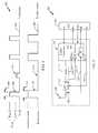
- the front end 200also comprises a digital baseband processor 210 , antenna 212 , receive power coupler 214 , antenna switch 216 , and duplexer 218 .
- the antenna switch 216comprises any suitable switching device or circuit and operates to selectively open and close switch (n) based on a switch control signal 228 to disconnect/connect the antenna 202 from/to the duplexer 218 so that signals can flow between the antenna 212 and the local WAN receiver 206 on a non-bypass signal path 230 .
- the antenna switch 216also operates to selectively open and close switch (b) based on the switch control signal 228 to disconnect/connect the antenna 202 from/to the LNA 224 of the receiver 206 so that signals can flow between the antenna 212 and the LNA 224 of the receiver 206 on a bypass signal path 232 .
- the duplexer 218is a filter such as a SAW filter, thin film bulk resonator (FBAR) filter, bulk acoustic wave filter (BAW) filter, microelectromechanical system (MEMS) filter or any other type of suitable filter.
- FBARthin film bulk resonator
- BAWbulk acoustic wave filter
- MEMSmicroelectromechanical system
- the receive power coupler 214comprises any suitable power coupler that operates to detect received signal power over any desired frequency band, such as a wide band (i.e., 0-12 GHz).
- the output 234 of the power coupler 214is input to a jammer detector (JD) 226 .
- JDjammer detector
- the power coupler 214has a small insertion loss (i.e., about 0.25 dB); however, such low signal loss does not appreciably affect performance.
- the jammer detector 226detects the levels of potential jamming signals in the power coupler output 234 and inputs this information to the digital BB processor 210 . For example, the detector 226 detects when the power level of one or more jamming signals in the power coupler output 234 exceeds a selected threshold (i.e., ⁇ 45 dBm) and inputs this information to the digital BB processor 210 .
- a selected thresholdi.e., ⁇ 45 dBm
- the output of the LNAs( 222 , 224 ) is coupled to the jammer detector 226 (shown as a dashed line) so that the power detection function is performed on the LNA output and not on the output 234 of the power coupler 214 .
- the power coupler 214is not needed and the jammer detector 226 will not be affected by signals that are filtered by other front end components, such as matching networks (not shown).
- the digital BB processor 210outputs the switch control signal 228 to control whether the front end 200 operates in a non-bypass mode or a bypass mode.
- the duplexer 218is bypassed so that signals received at the antenna 212 flow to the receiver 206 on the bypass path 232 enabling the receiver 206 to operate with improved sensitivity. Additional detail about the non-bypass and bypass modes is provided below.
- the digital BB processor 210sets the switch control signal 228 to control the switch (n) to connect the antenna 212 to the duplexer 218 and to control the switch (b) to disconnect the antenna 212 from the LNA 224 . Furthermore, the digital BB processor 210 sets the LNA control signal to enable the LNA 222 and disable the LNA 224 . This mode of operation can be utilized when the local related transmitter 204 is actively transmitting signals that can jam the receiver 206 . Thus, in the non-bypass operating mode, the duplexer 218 is utilized to suppress jamming signals.
- the non-bypass modeis also used when the power detector 226 detects the presence of jamming signals in either the output 234 of the power coupler 214 or the output of the LNAs ( 222 , 224 ) depending on the configuration used.
- the output of the detector 226is input to the digital BB processor 210 and based on this information, the processor 210 sets the switch control signal 228 to enable or disable the non-bypass mode.
- the duplexer 218includes an insertion loss of about 2 . 5 dB in the receive signal path 230 , which operates to degrade any signals that are passed to the receiver 206 .
- the received signalsare received at the LNA 222 with a much lower signal level.
- the receiver 206operates with less sensitivity.
- the digital BB processor 210sets the switch control signal 228 to control the switch (n) to disconnect the antenna 212 from the duplexer 218 and to control the switch (b) to connect the antenna 212 to the LNA 224 . Furthermore, the digital BB processor 210 sets the LNA control signal to disable the LNA 222 and enable the LNA 224 .
- the duplexer 218is bypassed so that signals received by the antenna 212 flow to the LNA 224 of the receiver 206 . Since the duplexer 218 is not in the signal path 232 , its insertion loss is not experienced by the received signals and therefore the receiver 206 operates with improved sensitivity.
- FIG. 3shows an exemplary front end 300 that comprises the front end 200 shown in FIG. 2 with the addition of a local diversity receiver 302 .
- the front end 300is shown with one diversity receiver, the various aspects are suitable for use with multiple diversity receivers.
- the diversity receiver 302operates to provide a second WAN receive signal utilizing antenna 304 .
- a receive power coupler 306 , antenna switch 308 , and SAW filter 310are also utilized with the diversity receiver 302 to allow the diversity receiver 302 to operate in bypass mode to bypass the SAW filter 310 .
- the diversity receiver 302also comprises LNAs 316 , 318 and a second jammer detector 320 .
- the digital BB processor 210outputs the switch control signal 228 to control both antenna switches 216 , 308 to select either the non-bypass mode or the bypass mode.
- the processor 210also outputs the diversity LNA(D) control signal to enable the appropriate LNA (either 316 or 318 ) based on the selected mode.
- the processor 210knows when and at what power level a transmission from the transmitter 204 is to occur and sets the switch control signal 228 to select the non-bypass mode for either or both the receiver 206 and the diversity receiver 302 during these transmissions.
- the receive power coupler 306detects receive power and provides an output 322 that is input to the second jammer detector 320 .
- the second jammer detector 320detects the power level of the received signals over a selected frequency band (i.e., 0-12 GHz) and then outputs detection information to the second JD input of the processor 210 . Based on the received power detection information from the second jammer detector 320 , the processor 210 decides whether to enable the non-bypass mode or the bypass mode.
- the processor 210if the power of received jamming signals exceeds a selected threshold, the processor 210 enables the non-bypass mode of operation; otherwise, the processor 210 enables the bypass mode of operation.
- a diversity signal path and a primary signal pathcan be used independently or in combination to determine whether the non-bypass mode or the bypass mode is utilized for each of the receivers 206 and 302 .
- the antenna switches 216 and 306are used to route received signals to either the non-bypass or the bypass signal paths.
- the switches 216 and 306comprise any suitable antenna switching devices and may have a variety of switch configurations to implement the switching functions illustrated in FIG. 3 .
- the switches 216 and 306have a small insertion loss (i.e., about 0.25 dB); however, such low signal loss does not appreciably affect performance, and therefore virtually any switch configuration may be used to achieve the desired improvements described herein.
- pro-active operationoccurs when the processor 210 operates to set the operating mode based on knowledge of transmissions by a local related transmitter.
- the digital BB processor 210has knowledge about when and at what power level transmissions are to be performed by the local related transmitter 204 .
- the processor 210outputs the switch control signal to enable non-bypass mode.
- the processor 210outputs the switch control signal to enable bypass mode.
- reactive operationoccurs when the processor 210 operates to set the operating mode based on knowledge of received field jammers.
- the digital BB processor 210has knowledge about received field jammers from the jammer detector 226 . If the jammer detector 226 detects energy (in a selected frequency band) that is above a selected threshold, then the processor 210 determines that a field jammer is present and outputs the switch control signal 228 to enable the non-bypass mode. If no field jammers are detected by the jammer detector 226 , the processor 210 outputs the switch control signal 228 to enable the bypass mode.
- a slight time delay between the bypass and the non-bypass signal pathsmay be experienced.
- either signal pathmay utilize one or more matching networks (not shown) to provide impedance matching. This time delay difference between the two signal paths may interfere signal processing performed by the digital BB processor 210 .
- the digital BB processor 210comprises a delay compensator (DC) 324 that stores delay information associated with the non-bypass and bypass signal paths.
- the delay compensator 324comprises a processor, memory, registers or other functional elements (not shown) that operate to compensate for time delays associated with the bypass and non-bypass signal paths.
- the delay informationcan be determine at manufacture and loaded into delay compensator 324 at that time.
- the delay compensator 324uses the delay information to compensate for any signal time delays that may occur as a result of switching between the non-bypass and bypass signal paths.
- the delay compensator 324 and the digital BB processor 210can seamlessly compensate or correct for any time delays that may occur each time the received signals are routed between the non-bypass and bypass signal paths.
- FIG. 4shows an exemplary timing diagram 400 illustrating the operation of the front end 200 shown in FIG. 2 in a time division transmission environment.
- the local transmitter 204 and related receiver 206are communicating with a communication network utilizing a time division communication protocol, such as the Global System for Mobile communication (GSM), time division long term evolution (TD-LTE), Bluetooth or Wireless LAN.
- GSMGlobal System for Mobile communication
- TD-LTEtime division long term evolution
- BluetoothWireless LAN
- the diagram 400comprises a plot 402 of transmission time intervals associated with the transmitter 204 .
- a first transmission interval 406is shown during which the transmitter 204 is transmitting signals at a high power level.
- the duration of the transmissionis indicated at 408 .
- the digital BB processor 210knows about the operation of the transmitter 204 and during the transmission intervals shown in the plot 402 , the digital BB processor 210 outputs the switch control signal 228 to control the antenna switch 216 to couple the antenna 212 to the non-bypass signal path 230 during high power transmission intervals and couple the antenna to the bypass signal path 232 during time intervals where no transmissions or only low power transmissions occur.
- a transmission thresholdis defined (i.e., ⁇ 10 dBm) where transmissions above this threshold are considered high power transmissions, and transmissions below this threshold are considered low power transmissions.
- the plot 404shows the switch control signal, the mode selected during each transmission interval and the mode selected between transmission intervals.
- the non-bypass modeis enabled as indicated at 410 .
- the non-bypass modecontinues (time interval 412 ) until the transmission interval 406 is completed, at which time the mode is switched to the bypass mode (as shown at 414 ) until the next transmission interval where the transmission power level is greater than ⁇ 10 dBm.
- the switch control signalis set to produce the bypass mode as indicated at 414 .
- the selection of the bypass modemay also be used during Paging operations where only the receiver is powered up to receive any paging messages.
- the digital BB processor 210operates to control the mode selection based on the transmission power levels of the local related transmitter.
- FIG. 5shows a diagram of an exemplary front end 500 comprising a transceiver that includes receiver 506 that operates with improved sensitivity.
- the front end 500is suitable for use in a portable device comprising to communicate using any of multiple transmission technologies.
- the transceivermay be a WAN, WLAN, Bluetooth or other transceiver and it is desirable that the receiver 506 at the device operate with the highest sensitivity.
- receiverscomprise input filtering, such as a duplexer, which filters unwanted signals from jamming the receiver.
- input filteringsuch as a duplexer
- the input filteringmay be unnecessary, and may in fact, insert loss into the signal path that reduces sensitivity.
- the front end 500overcomes these and other deficiencies.
- the front end 500comprises digital signal processor (DSP) 526 , local related transmitter 504 , antenna 508 , receiver power coupler 510 , antenna switch 512 , duplexer 512 , and receiver 506 .
- DSPdigital signal processor
- the DSP 502outputs signals to be transmitted by the local related transmitter 504 and these signals are transmitted using the antenna 508 .
- the antenna 508also receives signals for processing by the receiver 506 .
- the switch 512routes signals received by the antenna 508 to the duplexer 514 where undesirable signals are filtered out.
- the duplexer 514may be a SAW filter that has some significant level of insertion loss, for example 1 to 3 dB.
- the output of the filter 512is input to the receiver 506 on a non-bypass signal path 524 for down conversion.
- the resulting BB signal (Rx)is input to the DSP 526 for processing.
- the DSP 526knows when and at what power levels transmissions by the local related transmitter 504 are to occur. During time intervals when there are no related transmissions or only low power related transmissions, the DSP 526 outputs a control signal 518 to the switch 512 causing the switch 512 to route received signals around the filter 514 , (i.e., using the bypass path 522 ) thereby bypassing the filter 514 and avoiding its insertion loss.
- the received signalsare received at the receiver 506 with the highest possible signal levels resulting in increased receiver sensitivity.
- the selection between the non-bypass and the bypass signal pathis made based on the received power of jamming signals received by the antenna 508 .
- received signal poweris detected by receive power coupler 510 .
- the output of the receive power coupler 510is input to jammer detector 516 .
- the jammer detector 516detects whether signal power is a selected frequency band, such as a wide band, is above a threshold value. Levels above the selected threshold indicate the presence of a jamming signal.
- the jammer detector 516communicates its detection result with the DSP 526 .
- the DSP 526can then output the switch control signal 518 to enable non-bypass mode if a jammer is detected or to enable bypass mode if no jammer is detected.
- the input to the jammer detector 516is provided by the output of the LNAs of the receiver 506 .
- the jammer detector 516operates as described above to detect jammers in the LNA output signal.
- the front end 500comprises a receiver 506 that operates with improved sensitivity in a device that operates to transmit information from a local related transmitter using any type of transmission protocol.
- FIG. 6shows an exemplary method 600 for operating a receiver to achieve improved sensitivity.
- the operations of the method 600are performed by the front end 500 .
- the receiveris initialized to operate in one of a non-bypass mode or a bypass mode.
- the digital BB processor 526sets the switch control signal 518 to control the antenna switch 512 to route signals received from antenna 508 to the duplexer 514 on a non-bypass signal path 524 or to route signals from the antenna 508 to the receiver 506 on a bypass signal path 522 .
- a jamming signaljammer
- the digital BB processor 526knows the power level of transmissions from the local related transmitter 504 . If the transmitted power level is to exceed a selected threshold, the method proceeds to block 608 . If the power level of the transmission is equal to or below the selected threshold, the method proceeds to block 614 .
- a bypass operating modeis enabled.
- the digital BB processor 526sets the switch control signal 518 to control the antenna switch 512 to route signals on a bypass signal path 522 that avoids the duplexer 514 .
- the signalsare received at the receiver 506 without experiencing the insertion loss of the duplexer 514 and therefore provide improved receiver sensitivity.
- a non-bypass modeis enabled.
- the digital BB processor 526sets the switch control signal 518 to control the antenna switch 512 to route signals on a non-bypass signal path 524 that includes the duplexer 514 .
- the signalsare filtered to remove jammers but also experience the insertion loss of the duplexer 514 .
- the signalsare thereafter received at the receiver 506 with lower signal levels resulting in the lower receiver sensitivity.
- an LNA at the receiveris selected.
- the appropriate LNAis selected based on the operating mode to receive signals from the antenna 508 .
- the processor 526outputs an LNA control signal (LNA) that controls the receiver 506 to enable the appropriate LNA.
- LNALNA control signal
- the receiveris operated in the selected mode and the method returns to block 604 to determine whether or not additional transmissions are detected.
- the method 600illustrates a method for operating a receiver in the front end to achieve improved sensitivity. It should be noted that the method 600 is just one implementation and that the operations of the method 600 may be rearranged or otherwise modified such that other implementations are possible.
- FIG. 7shows an exemplary method 700 for operating a receiver to achieve improved sensitivity.
- the operations of the method 700are performed by the front end 500 .
- the receiveris initialized to operate in one of a non-bypass mode or a bypass mode.
- the digital BB processor 526sets the switch control signal 518 to control the antenna switch 512 to route signals received from antenna 508 to the duplexer 514 on a non-bypass signal path 524 or to route signals from the antenna 508 to the receiver 506 on a bypass signal path 522 .
- the jammer detector 516detects signal level in the output 520 of the receive power coupler 510 . If energy in a selected band (for example, 0-12 GHz) is detected, the method proceeds to block 706 . If no energy in the selected band is detected, the method proceeds to block 714 . In another implementation, the jammer detector 516 detects the signal level at the output of an LNA of the receiver 506 .
- a bypass operating modeis enabled.
- the digital BB processor 526sets the switch control signal 518 to control the antenna switch 512 to route signals from the antenna 508 on a bypass signal path 522 that avoids the duplexer 514 .
- the signalsare received at the receiver 506 without experiencing the insertion loss of the duplexer 514 and therefore provide improved receiver sensitivity.
- a non-bypass modeis enabled.
- the digital BB processor 526sets the switch control signal 518 to control the antenna switch 512 to route signals on a non-bypass signal path 524 that includes the duplexer 514 .
- the signalsare filtered to remove jammers but also experience the insertion loss of the duplexer 514 .
- the signalsare thereafter received at the receiver 506 with lower signal levels resulting in the lower receiver sensitivity.
- an LNA at the receiveris selected.
- the appropriate LNAis selected based on the operating mode to receive signals from the antenna 508 .
- the processor 526outputs an LNA control signal (LNA) that controls the receiver 506 to enable the appropriate LNA.
- LNALNA control signal
- the receiveris operated in the selected mode and the method returns to block 704 to determine whether or not additional jammers are detected.
- the method 700illustrates a method for operating a receiver in the front end to achieve improved sensitivity. It should be noted that the method 700 is just one implementation and that the operations of the method 700 may be rearranged or otherwise modified such that other implementations are possible. It should also be noted that the operations of the methods 600 and 700 may be combined such that the selection between the non-bypass and bypass modes is based on related local transmissions and/or received jamming signals.
- FIG. 8shows a receiver apparatus 800 configured to operate with improved sensitivity.
- the apparatus 800is suitable for use in the front end 300 shown in FIG. 3 or in the front end 500 shown in FIG. 5 .
- the apparatus 800is implemented by one or more modules configured to provide the functions as described herein.
- each modulecomprises hardware and/or hardware executing software.
- the apparatus 800comprises a first module comprising means ( 802 ) for providing a non-bypass signal path to a receiver, the non-bypass signal path comprising a filter, which in an aspect comprises the signal path 524 .
- the apparatus 800also comprises a second module comprising means ( 804 ) for providing a bypass signal path to the receiver, the bypass signal path configured to bypass the filter, which in an aspect comprises the signal path 522 .
- the apparatus 800also comprises a third module comprising means ( 806 ) for coupling an antenna to the non-bypass signal path during time intervals when signals transmitted by a related local transmitter are transmitted with a signal power that exceeds a selected threshold, and for coupling the antenna to the bypass signal path during other time intervals, which in an aspect comprises the antenna switch 512 .
- the apparatus 800also comprises a fourth module comprising means ( 808 ) for coupling an antenna to the non-bypass signal path during time intervals when a jamming signal in a selected frequency range is received at the antenna with a signal power that exceeds a selected threshold, and for coupling the antenna to the bypass signal path during other time intervals, which in an aspect comprises the jammer detector 516 .
- transistor types and technologiesmay be substituted, rearranged or otherwise modified to achieve the same results.
- circuits shown utilizing PMOS transistorsmay be modified to use NMOS transistors and vice versa.
- the amplifiers disclosed hereinmay be realized using a variety of transistor types and technologies and are not limited to those transistor types and technologies illustrated in the Drawings.
- transistors typessuch as BJT, GaAs, MOSFET or any other transistor technology may be used.
- DSPDigital Signal Processor
- ASICApplication Specific Integrated Circuit
- FPGAField Programmable Gate Array
- a general purpose processormay be a microprocessor, but in the alternative, the processor may be any conventional processor, controller, microcontroller, or state machine.
- a processormay also be implemented as a combination of computing devices, e.g., a combination of a DSP and a microprocessor, a plurality of microprocessors, one or more microprocessors in conjunction with a DSP core, or any other such configuration.
- a software modulemay reside in Random Access Memory (RAM), flash memory, Read Only Memory (ROM), Electrically Programmable ROM (EPROM), Electrically Erasable Programmable ROM (EEPROM), registers, hard disk, a removable disk, a CD-ROM, or any other form of storage medium known in the art.
- An exemplary storage mediumis coupled to the processor such that the processor can read information from, and write information to, the storage medium.
- the storage mediummay be integral to the processor.
- the processor and the storage mediummay reside in an ASIC.
- the ASICmay reside in a user terminal.
- the processor and the storage mediummay reside as discrete components in a user terminal.
- the functions describedmay be implemented in hardware, software, firmware, or any combination thereof. If implemented in software, the functions may be stored on or transmitted over as one or more instructions or code on a computer-readable medium.
- Computer-readable mediaincludes both non-transitory computer storage media and communication media including any medium that facilitates transfer of a computer program from one place to another.
- a non-transitory storage mediamay be any available media that can be accessed by a computer.
- such computer-readable mediacan comprise RAM, ROM, EEPROM, CD-ROM or other optical disk storage, magnetic disk storage or other magnetic storage devices, or any other medium that can be used to carry or store desired program code in the form of instructions or data structures and that can be accessed by a computer.
- any connectionis properly termed a computer-readable medium.
- the softwareis transmitted from a website, server, or other remote source using a coaxial cable, fiber optic cable, twisted pair, digital subscriber line (DSL), or wireless technologies such as infrared, radio, and microwave
- the coaxial cable, fiber optic cable, twisted pair, DSL, or wireless technologiessuch as infrared, radio, and microwave are included in the definition of medium.
- Disk and discincludes compact disc (CD), laser disc, optical disc, digital versatile disc (DVD), floppy disk and blu-ray disc where disks usually reproduce data magnetically, while discs reproduce data optically with lasers. Combinations of the above should also be included within the scope of computer-readable media.
Landscapes
- Engineering & Computer Science (AREA)
- Computer Networks & Wireless Communication (AREA)
- Signal Processing (AREA)
- Transceivers (AREA)
Abstract
Description
1. Field
The present application relates generally to the operation and design of transceivers, and more particularly, to improving the sensitivity of receivers.
2. Background
High quality signal reception is especially important for the current generation of portable devices. Typically, such devices provide multiple services, such as wide area network (WAN) communication services, wireless local area network (WLAN) communication services, and various other communication services. A device may include several transceivers to provide such communication services. Accordingly, each transceiver within a device should be carefully designed to reject interfering signals and receive desired signals with high sensitivity.
Signal interference may be especially problematic in multi-radio coexistence scenarios where, for example, a portable device includes a WAN transceiver and a WLAN transceiver. In this coexistence scenario, strong radio frequency (RF) jamming signals can appear at the input of the WAN receiver due to transmissions by the local related WAN transmitter. Furthermore, jamming signals from external transmitters may also appear at the input to the WAN receiver. Such signals may jam the WAN receiver and thus interfere with WAN signal reception.
To address this problem, a filter, such as a duplexer, is typically inserted in the receive signal path to suppress jamming signals associated with transmissions by the local related WAN transmitter or external transmitters. Unfortunately, the filter introduces an insertion loss of up to approximately 2.5 dB into the receive signal path. Thus, at times when there are no jamming signals present, the received WAN signals still experience the insertion loss of the duplexer thereby reducing the sensitivity of the WAN receiver.
Therefore, it would be desirable to have an efficient way to overcome the insertion loss of a duplexer or other filter utilized in a radio front end to improve receiver sensitivity.
The foregoing aspects described herein will become more readily apparent by reference to the following description when taken in conjunction with the accompanying drawings wherein:
The detailed description set forth below in connection with the appended drawings is intended as a description of exemplary embodiments of the invention and is not intended to represent the only embodiments in which the invention can be practiced. The term “exemplary” used throughout this description means “serving as an example, instance, or illustration,” and should not necessarily be construed as preferred or advantageous over other exemplary embodiments. The detailed description includes specific details for the purpose of providing a thorough understanding of the exemplary embodiments of the invention. It will be apparent to those skilled in the art that the exemplary embodiments of the invention may be practiced without these specific details. In some instances, well known structures and devices are shown in block diagram form in order to avoid obscuring the novelty of the exemplary embodiments presented herein.
Thefront end 100 includes alocal WAN transceiver 102 that comprises localrelated transmitter 104 andreceiver 106 that transmit and receive voice, data, or other information over a communication network. Thetransceiver 102 is considered local because it is located within the communication device. Thetransmitter 104 andreceiver 106 are related in that they operate together to provide bidirectional communications with an external entity using a particular communication protocol. Aduplexer 108 filters and routes atransmit signal 110 from thetransmitter 104 to anantenna 112 for transmission. Signals received by theantenna 112 are input to theduplexer 108 where they are filtered and then input to a low noise amplifier (LNA)114 of therelated receiver 106. Thus, the localrelated transmitter 104 andreceiver 106 operate together to communicate with a wireless network using a WAN access technology.
The localrelated transmitter 104 andreceiver 106 communicate with a digital baseband (BB)processor 124. Thedigital BB processor 122 processes information that is transmitted or received using thelocal WAN transceiver 102. Thus, theprocessor 122 knows when and at what power level data will be transmitted by thetransmitter 104.
During operation of thefront end 100, a number of de-sensing events may occur to de-sense thereceiver 106. The following is a list of de-sensing events that may de-sense thereceiver 106, however, it should be noted that the list is not exhaustive and that other de-sensing events are possible.
- 1. Receive band noise from the
WAN transmitter 104 - 2. Jamming signals leaking from the
WAN transmitter 104 to theWAN receiver 106 - 3. Other jamming signals received by the antenna112 (i.e., jamming signals in a wide band, such as 0-12 GHz)
Theduplexer 108 is utilized to address the various de-sensing events listed above. For example, in one exemplary implementation, theduplexer 108 provides approximately 55 dB of rejection outside the receive signal band. This level of rejection reduces the maximum received signal power of a jamming signal so that the LNA114 operates properly.
Unfortunately, theduplexer 108 introduces approximately 2.5 dB of insertion loss (IL) which reduces the sensitivity of thereceiver 106. Accordingly, exemplary embodiments of the disclosed receiver with improved sensitivity operate to reduce or eliminate the signal loss introduced by theduplexer 108.
In various exemplary aspects, a receiver with improved sensitivity is disclosed. For the purpose of this description, the various aspects are described herein with reference to a WAN receiver; however, the various aspects are equally applicable to other types of receivers.
Theantenna switch 216 comprises any suitable switching device or circuit and operates to selectively open and close switch (n) based on aswitch control signal 228 to disconnect/connect theantenna 202 from/to theduplexer 218 so that signals can flow between theantenna 212 and thelocal WAN receiver 206 on anon-bypass signal path 230. Theantenna switch 216 also operates to selectively open and close switch (b) based on theswitch control signal 228 to disconnect/connect theantenna 202 from/to theLNA 224 of thereceiver 206 so that signals can flow between theantenna 212 and theLNA 224 of thereceiver 206 on abypass signal path 232.
Theduplexer 218 is a filter such as a SAW filter, thin film bulk resonator (FBAR) filter, bulk acoustic wave filter (BAW) filter, microelectromechanical system (MEMS) filter or any other type of suitable filter.
The receivepower coupler 214 comprises any suitable power coupler that operates to detect received signal power over any desired frequency band, such as a wide band (i.e., 0-12 GHz). Theoutput 234 of thepower coupler 214 is input to a jammer detector (JD)226. Thepower coupler 214 has a small insertion loss (i.e., about 0.25 dB); however, such low signal loss does not appreciably affect performance.
Thejammer detector 226 detects the levels of potential jamming signals in thepower coupler output 234 and inputs this information to thedigital BB processor 210. For example, thedetector 226 detects when the power level of one or more jamming signals in thepower coupler output 234 exceeds a selected threshold (i.e., −45 dBm) and inputs this information to thedigital BB processor 210.
In an optional implementation, the output of the LNAs (222,224) is coupled to the jammer detector226 (shown as a dashed line) so that the power detection function is performed on the LNA output and not on theoutput 234 of thepower coupler 214. In this implementation, thepower coupler 214 is not needed and thejammer detector 226 will not be affected by signals that are filtered by other front end components, such as matching networks (not shown).
Thedigital BB processor 210 outputs theswitch control signal 228 to control whether thefront end 200 operates in a non-bypass mode or a bypass mode. During operation in the bypass mode, theduplexer 218 is bypassed so that signals received at theantenna 212 flow to thereceiver 206 on thebypass path 232 enabling thereceiver 206 to operate with improved sensitivity. Additional detail about the non-bypass and bypass modes is provided below.
Non-Bypass Mode
To enable the non-bypass mode, thedigital BB processor 210 sets theswitch control signal 228 to control the switch (n) to connect theantenna 212 to theduplexer 218 and to control the switch (b) to disconnect theantenna 212 from theLNA 224. Furthermore, thedigital BB processor 210 sets the LNA control signal to enable theLNA 222 and disable theLNA 224. This mode of operation can be utilized when the localrelated transmitter 204 is actively transmitting signals that can jam thereceiver 206. Thus, in the non-bypass operating mode, theduplexer 218 is utilized to suppress jamming signals.
The non-bypass mode is also used when thepower detector 226 detects the presence of jamming signals in either theoutput 234 of thepower coupler 214 or the output of the LNAs (222,224) depending on the configuration used. The output of thedetector 226 is input to thedigital BB processor 210 and based on this information, theprocessor 210 sets theswitch control signal 228 to enable or disable the non-bypass mode.
Unfortunately, in the non-bypass mode, theduplexer 218 includes an insertion loss of about2.5 dB in the receivesignal path 230, which operates to degrade any signals that are passed to thereceiver 206. As a result, the received signals are received at theLNA 222 with a much lower signal level. Thus, in non-bypass mode, thereceiver 206 operates with less sensitivity.
Bypass Mode
To enable the bypass mode, thedigital BB processor 210 sets theswitch control signal 228 to control the switch (n) to disconnect theantenna 212 from theduplexer 218 and to control the switch (b) to connect theantenna 212 to theLNA 224. Furthermore, thedigital BB processor 210 sets the LNA control signal to disable theLNA 222 and enable theLNA 224. Thus, in the bypass operating mode, theduplexer 218 is bypassed so that signals received by theantenna 212 flow to theLNA 224 of thereceiver 206. Since theduplexer 218 is not in thesignal path 232, its insertion loss is not experienced by the received signals and therefore thereceiver 206 operates with improved sensitivity.
Thediversity receiver 302 operates to provide a second WAN receivesignal utilizing antenna 304. A receivepower coupler 306,antenna switch 308, andSAW filter 310 are also utilized with thediversity receiver 302 to allow thediversity receiver 302 to operate in bypass mode to bypass theSAW filter 310. Thediversity receiver 302 also comprisesLNAs second jammer detector 320.
During operation, thedigital BB processor 210 outputs theswitch control signal 228 to control bothantenna switches processor 210 also outputs the diversity LNA(D) control signal to enable the appropriate LNA (either316 or318) based on the selected mode.
In one implementation, theprocessor 210 knows when and at what power level a transmission from thetransmitter 204 is to occur and sets theswitch control signal 228 to select the non-bypass mode for either or both thereceiver 206 and thediversity receiver 302 during these transmissions. In another implementation, the receivepower coupler 306 detects receive power and provides anoutput 322 that is input to thesecond jammer detector 320. Thesecond jammer detector 320 detects the power level of the received signals over a selected frequency band (i.e., 0-12 GHz) and then outputs detection information to the second JD input of theprocessor 210. Based on the received power detection information from thesecond jammer detector 320, theprocessor 210 decides whether to enable the non-bypass mode or the bypass mode. For example, if the power of received jamming signals exceeds a selected threshold, theprocessor 210 enables the non-bypass mode of operation; otherwise, theprocessor 210 enables the bypass mode of operation. Thus, a diversity signal path and a primary signal path can be used independently or in combination to determine whether the non-bypass mode or the bypass mode is utilized for each of thereceivers
Alternate Switch Implementations
In various implementations, theantenna switches switches FIG. 3 . Theswitches
Pro-Active Operation
In various aspects, pro-active operation occurs when theprocessor 210 operates to set the operating mode based on knowledge of transmissions by a local related transmitter. For example, thedigital BB processor 210 has knowledge about when and at what power level transmissions are to be performed by the localrelated transmitter 204. During time intervals when the localrelated transmitter 204 is to transmit signals at relatively high signal power, theprocessor 210 outputs the switch control signal to enable non-bypass mode. During time intervals where no transmissions or low power transmissions are to occur, theprocessor 210 outputs the switch control signal to enable bypass mode.
Reactive Operation
In various aspects, reactive operation occurs when theprocessor 210 operates to set the operating mode based on knowledge of received field jammers. For example, thedigital BB processor 210 has knowledge about received field jammers from thejammer detector 226. If thejammer detector 226 detects energy (in a selected frequency band) that is above a selected threshold, then theprocessor 210 determines that a field jammer is present and outputs theswitch control signal 228 to enable the non-bypass mode. If no field jammers are detected by thejammer detector 226, theprocessor 210 outputs theswitch control signal 228 to enable the bypass mode.
Phase Adjustment
In various implementations, a slight time delay between the bypass and the non-bypass signal paths may be experienced. For example, either signal path may utilize one or more matching networks (not shown) to provide impedance matching. This time delay difference between the two signal paths may interfere signal processing performed by thedigital BB processor 210.
To compensate for any time delay differences between the bypass and non-bypass signal paths, thedigital BB processor 210 comprises a delay compensator (DC)324 that stores delay information associated with the non-bypass and bypass signal paths. Thedelay compensator 324 comprises a processor, memory, registers or other functional elements (not shown) that operate to compensate for time delays associated with the bypass and non-bypass signal paths. For example, the delay information can be determine at manufacture and loaded intodelay compensator 324 at that time. Thedelay compensator 324 uses the delay information to compensate for any signal time delays that may occur as a result of switching between the non-bypass and bypass signal paths. As a result, thedelay compensator 324 and thedigital BB processor 210 can seamlessly compensate or correct for any time delays that may occur each time the received signals are routed between the non-bypass and bypass signal paths.
The diagram400 comprises aplot 402 of transmission time intervals associated with thetransmitter 204. For example, afirst transmission interval 406 is shown during which thetransmitter 204 is transmitting signals at a high power level. The duration of the transmission is indicated at408.
Thedigital BB processor 210 knows about the operation of thetransmitter 204 and during the transmission intervals shown in theplot 402, thedigital BB processor 210 outputs theswitch control signal 228 to control theantenna switch 216 to couple theantenna 212 to thenon-bypass signal path 230 during high power transmission intervals and couple the antenna to thebypass signal path 232 during time intervals where no transmissions or only low power transmissions occur. For example, a transmission threshold is defined (i.e., −10 dBm) where transmissions above this threshold are considered high power transmissions, and transmissions below this threshold are considered low power transmissions.
Thus, theplot 404 shows the switch control signal, the mode selected during each transmission interval and the mode selected between transmission intervals. For example, just before the start of a high power transmission during thetransmission interval 406, the non-bypass mode is enabled as indicated at410. The non-bypass mode continues (time interval412) until thetransmission interval 406 is completed, at which time the mode is switched to the bypass mode (as shown at414) until the next transmission interval where the transmission power level is greater than −10 dBm. For example, at transmission interval416 a low power transmission occurs and the switch control signal is set to produce the bypass mode as indicated at414. It should also be noted that the selection of the bypass mode may also be used during Paging operations where only the receiver is powered up to receive any paging messages. Thus, thedigital BB processor 210 operates to control the mode selection based on the transmission power levels of the local related transmitter.
Typically receivers comprise input filtering, such as a duplexer, which filters unwanted signals from jamming the receiver. However, when such jammers are not present or present at very low power levels, the input filtering may be unnecessary, and may in fact, insert loss into the signal path that reduces sensitivity. Thefront end 500 overcomes these and other deficiencies.
Thefront end 500 comprises digital signal processor (DSP)526, localrelated transmitter 504,antenna 508,receiver power coupler 510,antenna switch 512,duplexer 512, andreceiver 506.
TheDSP 502 outputs signals to be transmitted by the localrelated transmitter 504 and these signals are transmitted using theantenna 508. Theantenna 508 also receives signals for processing by thereceiver 506. Theswitch 512 routes signals received by theantenna 508 to theduplexer 514 where undesirable signals are filtered out. For example, theduplexer 514 may be a SAW filter that has some significant level of insertion loss, for example 1 to 3 dB. The output of thefilter 512 is input to thereceiver 506 on anon-bypass signal path 524 for down conversion. The resulting BB signal (Rx) is input to theDSP 526 for processing.
Unfortunately, if no jamming signals or only low power jamming signals are present in the signals received by theantenna 508, the filtering performed by theduplexer 512 may not be needed but its insertion loss will still reduce the sensitivity of thereceiver 506. In an exemplary implementation, theDSP 526 knows when and at what power levels transmissions by the localrelated transmitter 504 are to occur. During time intervals when there are no related transmissions or only low power related transmissions, theDSP 526 outputs acontrol signal 518 to theswitch 512 causing theswitch 512 to route received signals around thefilter 514, (i.e., using the bypass path522) thereby bypassing thefilter 514 and avoiding its insertion loss. The received signals are received at thereceiver 506 with the highest possible signal levels resulting in increased receiver sensitivity.
In another implementation, the selection between the non-bypass and the bypass signal path is made based on the received power of jamming signals received by theantenna 508. For example, received signal power is detected by receivepower coupler 510. The output of the receivepower coupler 510 is input tojammer detector 516. Thejammer detector 516 detects whether signal power is a selected frequency band, such as a wide band, is above a threshold value. Levels above the selected threshold indicate the presence of a jamming signal. Thejammer detector 516 communicates its detection result with theDSP 526. TheDSP 526 can then output theswitch control signal 518 to enable non-bypass mode if a jammer is detected or to enable bypass mode if no jammer is detected. In another implementation, the input to thejammer detector 516 is provided by the output of the LNAs of thereceiver 506. Thejammer detector 516 operates as described above to detect jammers in the LNA output signal.
Therefore, thefront end 500 comprises areceiver 506 that operates with improved sensitivity in a device that operates to transmit information from a local related transmitter using any type of transmission protocol.
Atblock 602, the receiver is initialized to operate in one of a non-bypass mode or a bypass mode. For example, thedigital BB processor 526 sets theswitch control signal 518 to control theantenna switch 512 to route signals received fromantenna 508 to theduplexer 514 on anon-bypass signal path 524 or to route signals from theantenna 508 to thereceiver 506 on abypass signal path 522.
Atblock 604, a determination is made as to whether a jamming signal (jammer) from a local related transmitter is detected. For example, thedigital BB processor 526 knows when transmissions from the localrelated transmitter 504 are to occur. If a transmission is to occur, the method proceeds to block606. If no transmission is to occur, the method proceeds to block614.
Atblock 606, a determination is made as to whether the detected transmission is (or will be) above a power level threshold. For example, thedigital BB processor 526 knows the power level of transmissions from the localrelated transmitter 504. If the transmitted power level is to exceed a selected threshold, the method proceeds to block608. If the power level of the transmission is equal to or below the selected threshold, the method proceeds to block614.
Atblock 614, a bypass operating mode is enabled. For example, thedigital BB processor 526 sets theswitch control signal 518 to control theantenna switch 512 to route signals on abypass signal path 522 that avoids theduplexer 514. In this configuration, the signals are received at thereceiver 506 without experiencing the insertion loss of theduplexer 514 and therefore provide improved receiver sensitivity.
Atblock 608, a non-bypass mode is enabled. For example, thedigital BB processor 526 sets theswitch control signal 518 to control theantenna switch 512 to route signals on anon-bypass signal path 524 that includes theduplexer 514. In this configuration, the signals are filtered to remove jammers but also experience the insertion loss of theduplexer 514. The signals are thereafter received at thereceiver 506 with lower signal levels resulting in the lower receiver sensitivity.
Atblock 610, an LNA at the receiver is selected. For example, in an implementation where the receiver comprises multiple LNAs, the appropriate LNA is selected based on the operating mode to receive signals from theantenna 508. In one implementation, theprocessor 526 outputs an LNA control signal (LNA) that controls thereceiver 506 to enable the appropriate LNA.
Atblock 614, the receiver is operated in the selected mode and the method returns to block604 to determine whether or not additional transmissions are detected.
Thus, themethod 600 illustrates a method for operating a receiver in the front end to achieve improved sensitivity. It should be noted that themethod 600 is just one implementation and that the operations of themethod 600 may be rearranged or otherwise modified such that other implementations are possible.
Atblock 702, the receiver is initialized to operate in one of a non-bypass mode or a bypass mode. For example, thedigital BB processor 526 sets theswitch control signal 518 to control theantenna switch 512 to route signals received fromantenna 508 to theduplexer 514 on anon-bypass signal path 524 or to route signals from theantenna 508 to thereceiver 506 on abypass signal path 522.
Atblock 704, a determination is made as to whether a jamming signal (jammer) from an external transmitter is detected. For example, thejammer detector 516 detects signal level in theoutput 520 of the receivepower coupler 510. If energy in a selected band (for example, 0-12 GHz) is detected, the method proceeds to block706. If no energy in the selected band is detected, the method proceeds to block714. In another implementation, thejammer detector 516 detects the signal level at the output of an LNA of thereceiver 506.
Atblock 706, a determination is made as to whether the jamming signal is above a power level threshold. For example, thejammer detector 516 operates to determine whether detected signal energy is above a selected threshold. If the signal energy is above the selected threshold, the method proceeds to block708. If the signal energy is equal to or below the selected threshold, the method proceeds to block714.
Atblock 714, a bypass operating mode is enabled. For example, thedigital BB processor 526 sets theswitch control signal 518 to control theantenna switch 512 to route signals from theantenna 508 on abypass signal path 522 that avoids theduplexer 514. In this configuration, the signals are received at thereceiver 506 without experiencing the insertion loss of theduplexer 514 and therefore provide improved receiver sensitivity.
Atblock 708, a non-bypass mode is enabled. For example, thedigital BB processor 526 sets theswitch control signal 518 to control theantenna switch 512 to route signals on anon-bypass signal path 524 that includes theduplexer 514. In this configuration, the signals are filtered to remove jammers but also experience the insertion loss of theduplexer 514. The signals are thereafter received at thereceiver 506 with lower signal levels resulting in the lower receiver sensitivity.
Atblock 710, an LNA at the receiver is selected. For example, in an implementation where the receiver comprises multiple LNAs, the appropriate LNA is selected based on the operating mode to receive signals from theantenna 508. In one implementation, theprocessor 526 outputs an LNA control signal (LNA) that controls thereceiver 506 to enable the appropriate LNA.
Atblock 714, the receiver is operated in the selected mode and the method returns to block704 to determine whether or not additional jammers are detected.
Thus, themethod 700 illustrates a method for operating a receiver in the front end to achieve improved sensitivity. It should be noted that themethod 700 is just one implementation and that the operations of themethod 700 may be rearranged or otherwise modified such that other implementations are possible. It should also be noted that the operations of themethods
Theapparatus 800 comprises a first module comprising means (802) for providing a non-bypass signal path to a receiver, the non-bypass signal path comprising a filter, which in an aspect comprises thesignal path 524.
Theapparatus 800 also comprises a second module comprising means (804) for providing a bypass signal path to the receiver, the bypass signal path configured to bypass the filter, which in an aspect comprises thesignal path 522.
Theapparatus 800 also comprises a third module comprising means (806) for coupling an antenna to the non-bypass signal path during time intervals when signals transmitted by a related local transmitter are transmitted with a signal power that exceeds a selected threshold, and for coupling the antenna to the bypass signal path during other time intervals, which in an aspect comprises theantenna switch 512.
Theapparatus 800 also comprises a fourth module comprising means (808) for coupling an antenna to the non-bypass signal path during time intervals when a jamming signal in a selected frequency range is received at the antenna with a signal power that exceeds a selected threshold, and for coupling the antenna to the bypass signal path during other time intervals, which in an aspect comprises thejammer detector 516.
Those of skill in the art would understand that information and signals may be represented or processed using any of a variety of different technologies and techniques. For example, data, instructions, commands, information, signals, bits, symbols, and chips that may be referenced throughout the above description may be represented by voltages, currents, electromagnetic waves, magnetic fields or particles, optical fields or particles, or any combination thereof. It is further noted that transistor types and technologies may be substituted, rearranged or otherwise modified to achieve the same results. For example, circuits shown utilizing PMOS transistors may be modified to use NMOS transistors and vice versa. Thus, the amplifiers disclosed herein may be realized using a variety of transistor types and technologies and are not limited to those transistor types and technologies illustrated in the Drawings. For example, transistors types such as BJT, GaAs, MOSFET or any other transistor technology may be used.
Those of skill would further appreciate that the various illustrative logical blocks, modules, circuits, and algorithm steps described in connection with the embodiments disclosed herein may be implemented as electronic hardware, computer software, or combinations of both. To clearly illustrate this interchangeability of hardware and software, various illustrative components, blocks, modules, circuits, and steps have been described above generally in terms of their functionality. Whether such functionality is implemented as hardware or software depends upon the particular application and design constraints imposed on the overall system. Skilled artisans may implement the described functionality in varying ways for each particular application, but such implementation decisions should not be interpreted as causing a departure from the scope of the exemplary embodiments of the invention.
The various illustrative logical blocks, modules, and circuits described in connection with the embodiments disclosed herein may be implemented or performed with a general purpose processor, a Digital Signal Processor (DSP), an Application Specific Integrated Circuit (ASIC), a Field Programmable Gate Array (FPGA) or other programmable logic device, discrete gate or transistor logic, discrete hardware components, or any combination thereof designed to perform the functions described herein. A general purpose processor may be a microprocessor, but in the alternative, the processor may be any conventional processor, controller, microcontroller, or state machine. A processor may also be implemented as a combination of computing devices, e.g., a combination of a DSP and a microprocessor, a plurality of microprocessors, one or more microprocessors in conjunction with a DSP core, or any other such configuration.
The steps of a method or algorithm described in connection with the embodiments disclosed herein may be embodied directly in hardware, in a software module executed by a processor, or in a combination of the two. A software module may reside in Random Access Memory (RAM), flash memory, Read Only Memory (ROM), Electrically Programmable ROM (EPROM), Electrically Erasable Programmable ROM (EEPROM), registers, hard disk, a removable disk, a CD-ROM, or any other form of storage medium known in the art. An exemplary storage medium is coupled to the processor such that the processor can read information from, and write information to, the storage medium. In the alternative, the storage medium may be integral to the processor. The processor and the storage medium may reside in an ASIC. The ASIC may reside in a user terminal. In the alternative, the processor and the storage medium may reside as discrete components in a user terminal.
In one or more exemplary embodiments, the functions described may be implemented in hardware, software, firmware, or any combination thereof. If implemented in software, the functions may be stored on or transmitted over as one or more instructions or code on a computer-readable medium. Computer-readable media includes both non-transitory computer storage media and communication media including any medium that facilitates transfer of a computer program from one place to another. A non-transitory storage media may be any available media that can be accessed by a computer. By way of example, and not limitation, such computer-readable media can comprise RAM, ROM, EEPROM, CD-ROM or other optical disk storage, magnetic disk storage or other magnetic storage devices, or any other medium that can be used to carry or store desired program code in the form of instructions or data structures and that can be accessed by a computer. Also, any connection is properly termed a computer-readable medium. For example, if the software is transmitted from a website, server, or other remote source using a coaxial cable, fiber optic cable, twisted pair, digital subscriber line (DSL), or wireless technologies such as infrared, radio, and microwave, then the coaxial cable, fiber optic cable, twisted pair, DSL, or wireless technologies such as infrared, radio, and microwave are included in the definition of medium. Disk and disc, as used herein, includes compact disc (CD), laser disc, optical disc, digital versatile disc (DVD), floppy disk and blu-ray disc where disks usually reproduce data magnetically, while discs reproduce data optically with lasers. Combinations of the above should also be included within the scope of computer-readable media.
The description of the disclosed exemplary embodiments is provided to enable any person skilled in the art to make or use the invention. Various modifications to these exemplary embodiments will be readily apparent to those skilled in the art, and the generic principles defined herein may be applied to other embodiments without departing from the spirit or scope of the invention. Thus, the invention is not intended to be limited to the exemplary embodiments shown herein but is to be accorded the widest scope consistent with the principles and novel features disclosed herein.
Claims (12)
1. An apparatus comprising:
a non-bypass signal path coupled to a receiver, the non-bypass signal path comprising a filter;
a bypass signal path coupled to the receiver, the bypass signal path configure to bypass the filter;
a processor configured to output a control signal that indicates predetermined time intervals when signals are transmitted by a related local transmitter with a signal power that exceeds a selected threshold, the control signal output prior to the signal being received; and
a switch configured to receive the control signal, and in response, to couple an antenna to the non-bypass signal path during the predetermined time intervals and to couple the antenna to the bypass signal path during other time intervals.
2. The apparatus ofclaim 1 , the filter comprising at least one of a SAW filter, a FBAR filter, a BAW filter, and a MEMS filter.
3. The apparatus ofclaim 1 , the receiver comprising a first low noise amplifier (LNA) coupled to the non-bypass signal path and a second LNA coupled to the bypass signal path.
4. The apparatus ofclaim 1 , the processor comprising a baseband processor.
5. The apparatus ofclaim 1 , the processor configured to enable a first amplifier to receive signals from the antenna during the predetermined time intervals and to enable a second amplifier to receive the signals from the antenna during the other time intervals.
6. An apparatus comprising:
means for providing a non-bypass signal path to a receiver, the non-bypass signal comprising a filter;
means for providing a bypass signal path to the receiver, the bypass signal path configured to bypass the filter;
means for outputting a control signal that indicates predetermined time intervals when signals are transmitted by a related local transmitter with a signal power that exceeds a selected threshold, the control signal output prior to the signal being received; and
means for receiving the control signal, and in response, to couple an antenna to the non-bypass signal path during the predetermined time intervals and to couple the antenna to the bypass signal path during other time intervals.
7. The apparatus ofclaim 6 , the filter comprising at least one of a SAW filter, a FBAR filter, a BAW filter, and a MEMS filter.
8. The apparatus ofclaim 6 , the receiver comprising a first low noise amplifier (LNA) coupled to the non-bypass signal path and a second LNA coupled to the bypass signal path.
9. A method comprising:
detecting whether a local transmitter is to transmit a signal with a signal power that exceeds a selected threshold;
enabling a non-bypass mode prior to receiving the transmitted signal if the local transmitter is to transmit the signal with the signal power that exceeds the selected threshold; and
enabling a bypass mode prior to receiving the transmitted signal if the local transmitter will not transmit the signal with the signal power that exceeds the selected threshold.
10. The method ofclaim 9 , said enabling the non-bypass mode comprising coupling an antenna to a receiver using a non-bypass signal path configured to provide signal filtering.
11. The method ofclaim 10 , said enabling the bypass mode comprising coupling the antenna to the receiver using a bypass signal path configured to bypass the signal filtering.
12. The method ofclaim 11 , further comprising:
coupling a first low noise amplifier (LNA) to the non-bypass signal path; and
coupling a second LNA to the bypass signal path.
Priority Applications (2)
| Application Number | Priority Date | Filing Date | Title |
|---|---|---|---|
| US13/172,660US9154179B2 (en) | 2011-06-29 | 2011-06-29 | Receiver with bypass mode for improved sensitivity |
| PCT/US2012/045129WO2013003820A1 (en) | 2011-06-29 | 2012-06-29 | Receiver with bypass mode for improved sensitivity |
Applications Claiming Priority (1)
| Application Number | Priority Date | Filing Date | Title |
|---|---|---|---|
| US13/172,660US9154179B2 (en) | 2011-06-29 | 2011-06-29 | Receiver with bypass mode for improved sensitivity |
Publications (2)
| Publication Number | Publication Date |
|---|---|
| US20130003617A1 US20130003617A1 (en) | 2013-01-03 |
| US9154179B2true US9154179B2 (en) | 2015-10-06 |
Family
ID=46513869
Family Applications (1)
| Application Number | Title | Priority Date | Filing Date |
|---|---|---|---|
| US13/172,660Expired - Fee RelatedUS9154179B2 (en) | 2011-06-29 | 2011-06-29 | Receiver with bypass mode for improved sensitivity |
Country Status (2)
| Country | Link |
|---|---|
| US (1) | US9154179B2 (en) |
| WO (1) | WO2013003820A1 (en) |
Cited By (26)
| Publication number | Priority date | Publication date | Assignee | Title |
|---|---|---|---|---|
| US20160020738A1 (en)* | 2014-07-16 | 2016-01-21 | Samsung Electronics Co., Ltd. | Diversity amp module and apparatus comprising the same |
| US9693250B1 (en) | 2015-07-16 | 2017-06-27 | Viasat, Inc. | Systems and methods for monitoring electromagnetic compatibility |
| US10432272B1 (en) | 2018-11-05 | 2019-10-01 | XCOM Labs, Inc. | Variable multiple-input multiple-output downlink user equipment |
| US10659112B1 (en) | 2018-11-05 | 2020-05-19 | XCOM Labs, Inc. | User equipment assisted multiple-input multiple-output downlink configuration |
| US10686485B1 (en)* | 2018-12-06 | 2020-06-16 | Qorvo Us, Inc. | High isolation duplexer/quasi circulator with two quadrature couplers |
| US10686502B1 (en) | 2019-04-29 | 2020-06-16 | XCOM Labs, Inc. | Downlink user equipment selection |
| US10735057B1 (en) | 2019-04-29 | 2020-08-04 | XCOM Labs, Inc. | Uplink user equipment selection |
| US10756767B1 (en) | 2019-02-05 | 2020-08-25 | XCOM Labs, Inc. | User equipment for wirelessly communicating cellular signal with another user equipment |
| US10756782B1 (en) | 2019-04-26 | 2020-08-25 | XCOM Labs, Inc. | Uplink active set management for multiple-input multiple-output communications |
| US10756795B2 (en) | 2018-12-18 | 2020-08-25 | XCOM Labs, Inc. | User equipment with cellular link and peer-to-peer link |
| US10756860B2 (en) | 2018-11-05 | 2020-08-25 | XCOM Labs, Inc. | Distributed multiple-input multiple-output downlink configuration |
| US10756686B2 (en) | 2018-11-07 | 2020-08-25 | Mediatek Inc. | Band sharing technique of receiver |
| US10812216B2 (en) | 2018-11-05 | 2020-10-20 | XCOM Labs, Inc. | Cooperative multiple-input multiple-output downlink scheduling |
| US11032841B2 (en) | 2019-04-26 | 2021-06-08 | XCOM Labs, Inc. | Downlink active set management for multiple-input multiple-output communications |
| US11063645B2 (en) | 2018-12-18 | 2021-07-13 | XCOM Labs, Inc. | Methods of wirelessly communicating with a group of devices |
| US11290172B2 (en) | 2018-11-27 | 2022-03-29 | XCOM Labs, Inc. | Non-coherent cooperative multiple-input multiple-output communications |
| US11330649B2 (en) | 2019-01-25 | 2022-05-10 | XCOM Labs, Inc. | Methods and systems of multi-link peer-to-peer communications |
| US11411779B2 (en) | 2020-03-31 | 2022-08-09 | XCOM Labs, Inc. | Reference signal channel estimation |
| US11411778B2 (en) | 2019-07-12 | 2022-08-09 | XCOM Labs, Inc. | Time-division duplex multiple input multiple output calibration |
| US11515973B2 (en) | 2020-05-26 | 2022-11-29 | XCOM Labs, Inc. | Interference-aware beamforming |
| US11831480B2 (en) | 2020-10-19 | 2023-11-28 | XCOM Labs, Inc. | Reference signal for wireless communications |
| US11877311B2 (en) | 2020-10-30 | 2024-01-16 | Virewirx, Inc. | Rate selection in multiple-input multiple-output communication systems |
| US20240056106A1 (en)* | 2022-08-09 | 2024-02-15 | Skyworks Solutions, Inc. | Rf front-end module with band isolation |
| US12068953B2 (en) | 2020-04-15 | 2024-08-20 | Virewirx, Inc. | Wireless network multipoint association and diversity |
| US12232219B2 (en) | 2021-05-14 | 2025-02-18 | Virewirx, Inc. | Scrambling identifiers for wireless communication systems |
| US12407394B2 (en) | 2020-12-16 | 2025-09-02 | Virewirx, Inc. | Wireless communication with quasi-omni and directional beams |
Families Citing this family (29)
| Publication number | Priority date | Publication date | Assignee | Title |
|---|---|---|---|---|
| US9026070B2 (en)* | 2003-12-18 | 2015-05-05 | Qualcomm Incorporated | Low-power wireless diversity receiver with multiple receive paths |
| US9450665B2 (en) | 2005-10-19 | 2016-09-20 | Qualcomm Incorporated | Diversity receiver for wireless communication |
| US9178669B2 (en) | 2011-05-17 | 2015-11-03 | Qualcomm Incorporated | Non-adjacent carrier aggregation architecture |
| US9252827B2 (en) | 2011-06-27 | 2016-02-02 | Qualcomm Incorporated | Signal splitting carrier aggregation receiver architecture |
| US9882602B2 (en) | 2011-06-29 | 2018-01-30 | Qualcomm Incorporated | Global navigation satellite system receiver with filter bypass mode for improved sensitivity |
| US12081243B2 (en) | 2011-08-16 | 2024-09-03 | Qualcomm Incorporated | Low noise amplifiers with combined outputs |
| US8774334B2 (en) | 2011-11-09 | 2014-07-08 | Qualcomm Incorporated | Dynamic receiver switching |
| US9172402B2 (en) | 2012-03-02 | 2015-10-27 | Qualcomm Incorporated | Multiple-input and multiple-output carrier aggregation receiver reuse architecture |
| US9362958B2 (en) | 2012-03-02 | 2016-06-07 | Qualcomm Incorporated | Single chip signal splitting carrier aggregation receiver architecture |
| US9118439B2 (en) | 2012-04-06 | 2015-08-25 | Qualcomm Incorporated | Receiver for imbalanced carriers |
| US9154356B2 (en) | 2012-05-25 | 2015-10-06 | Qualcomm Incorporated | Low noise amplifiers for carrier aggregation |
| US9867194B2 (en) | 2012-06-12 | 2018-01-09 | Qualcomm Incorporated | Dynamic UE scheduling with shared antenna and carrier aggregation |
| US9300420B2 (en) | 2012-09-11 | 2016-03-29 | Qualcomm Incorporated | Carrier aggregation receiver architecture |
| US9515695B2 (en)* | 2012-09-26 | 2016-12-06 | Intel Deutschland Gmbh | Bypassing duplex filter |
| US9543903B2 (en) | 2012-10-22 | 2017-01-10 | Qualcomm Incorporated | Amplifiers with noise splitting |
| US8995591B2 (en) | 2013-03-14 | 2015-03-31 | Qualcomm, Incorporated | Reusing a single-chip carrier aggregation receiver to support non-cellular diversity |
| US9337878B2 (en) | 2013-12-16 | 2016-05-10 | Motorola Solutions, Inc. | Dual watch radio frequency receiver |
| US9847804B2 (en)* | 2014-04-30 | 2017-12-19 | Skyworks Solutions, Inc. | Bypass path loss reduction |
| US10424822B2 (en) | 2015-10-14 | 2019-09-24 | Wilson Electronics, Llc | Multi-common port multiband filters |
| EP3363124A4 (en)* | 2015-10-14 | 2020-01-15 | Wilson Electronics, LLC | SIGNAL BOOSTER |
| US10177722B2 (en) | 2016-01-12 | 2019-01-08 | Qualcomm Incorporated | Carrier aggregation low-noise amplifier with tunable integrated power splitter |
| US10772052B2 (en)* | 2017-06-16 | 2020-09-08 | Qualcomm Incorporated | Controlling coexistent radio systems in a wireless device |
| US10361745B2 (en)* | 2017-06-28 | 2019-07-23 | Qualcomm Incorporated | Systems and methods for reducing transmit and receive power via a T/R switch |
| CN109088653A (en)* | 2018-08-15 | 2018-12-25 | 维沃移动通信有限公司 | A kind of communication control unit, method and mobile terminal |
| KR102833887B1 (en)* | 2018-12-11 | 2025-07-14 | 삼성전자 주식회사 | electronic device for attenuating at least a portion of received signal via antenna and method for controlling communication signal |
| CN110098840B (en)* | 2019-04-30 | 2021-01-08 | 维沃移动通信有限公司 | Radio frequency device and terminal equipment |
| CN115298963A (en)* | 2020-04-06 | 2022-11-04 | 夏普株式会社 | Wireless device |
| WO2024030942A2 (en)* | 2022-08-04 | 2024-02-08 | Qualcomm Incorporated | Measurement of jammers due to antenna coupling |
| US20240372642A1 (en)* | 2023-05-05 | 2024-11-07 | Qualcomm Incorporated | Proactive jammer protection of receiver from transmit signal of integrated transmitter |
Citations (301)
| Publication number | Priority date | Publication date | Assignee | Title |
|---|---|---|---|---|
| US3911364A (en) | 1974-05-09 | 1975-10-07 | Bell Telephone Labor Inc | Cophasing combiner with cochannel signal selector |
| US4035729A (en) | 1976-05-21 | 1977-07-12 | General Electric Company | Audio signal quality indicating circuit |
| US4035728A (en) | 1975-01-09 | 1977-07-12 | Nippon Electric Company, Ltd. | Diversity receiving system |
| US4246655A (en) | 1977-10-18 | 1981-01-20 | Parker Bernhard D | Circuit for providing an indication of signal/noise ratio in a selector diversity system |
| US4326294A (en) | 1979-02-13 | 1982-04-20 | Nippon Telegraph & Telephone Public Corporation | Space diversity reception system having compensation means of multipath effect |
| US4715048A (en) | 1986-05-02 | 1987-12-22 | Canadian Patents And Development Limited | Frequency offset diversity receiving system |
| US4742563A (en) | 1985-06-11 | 1988-05-03 | Nec Corporation | System and method for diversity reception of signals |
| US4756023A (en) | 1985-07-22 | 1988-07-05 | Nec Corporation | Diversity reception radio receiver |
| US4969207A (en) | 1987-03-20 | 1990-11-06 | Nippon Telegraph And Telephone Corporation | Radio receiver with reception deterioration compensation |
| US5056411A (en) | 1988-09-15 | 1991-10-15 | Gec-Macroni Limited | Course recommendation display |
| US5128630A (en) | 1991-05-03 | 1992-07-07 | Motorola, Inc. | High speed fully differential operational amplifier |
| JPH05227234A (en) | 1992-02-14 | 1993-09-03 | Sony Corp | Receiver |
| US5291519A (en) | 1991-02-22 | 1994-03-01 | Nec Corporation | Digital mobile communications terminal equipment and receiving method therefor |
| US5321850A (en) | 1991-10-09 | 1994-06-14 | Telefonaktiebolaget L M Ericsson | Diversity radio receiver automatic frequency control |
| US5345601A (en) | 1991-08-07 | 1994-09-06 | Small Power Communication Systems Research Laboratories Co., Ltd. | Harmonic-frequency communication system with improved diversity scheme |
| JPH0730452A (en) | 1993-07-12 | 1995-01-31 | Fujitsu Ltd | Receiver circuit |
| US5390342A (en) | 1990-03-14 | 1995-02-14 | Pioneer Electronic Corporation | Receiver using selective diversity receiving system |
| JPH07221684A (en) | 1994-02-09 | 1995-08-18 | Hitachi Ltd | Mobile terminal for mobile communication |
| US5559838A (en) | 1993-12-01 | 1996-09-24 | Hitachi, Ltd. | Diversity receiving apparatus |
| US5566364A (en) | 1994-01-31 | 1996-10-15 | Nec Corporation | Power saving portable radio communication device with diversity reception |
| JPH09116458A (en) | 1995-10-16 | 1997-05-02 | N T T Ido Tsushinmo Kk | Multiband high frequency circuit for mobile radio machine |
| US5694396A (en) | 1994-09-30 | 1997-12-02 | Lucent Technologies Inc. | Method and apparatus for processing multicarrier signals |
| US5697083A (en) | 1994-09-02 | 1997-12-09 | Mitsubishi Denki Kabushiki Kaisha | Diversity receiver |
| US5761613A (en) | 1994-12-02 | 1998-06-02 | U.S. Philips Corporation | Diversity receiver |
| US5794159A (en) | 1996-08-07 | 1998-08-11 | Nokia Mobile Phones Limited | Dual band mobile station employing cross-connected transmitter and receiver circuits |
| US5805643A (en) | 1993-02-26 | 1998-09-08 | Kabushiki Kaisha Toshiba | Diversity receiver system used in digital communication |
| US5805989A (en) | 1994-10-05 | 1998-09-08 | Mitsubishi Denki Kabushiki Kaisha | Radio communication apparatus |
| US5835853A (en) | 1996-01-12 | 1998-11-10 | Matsushita Electric Industrial Co., Ltd. | Two band receiver |
| JPH11127300A (en) | 1997-10-22 | 1999-05-11 | Canon Inc | Wireless communication device and method |
| US5940452A (en) | 1995-11-29 | 1999-08-17 | Motorola, Inc. | Dual mode radio subscriber unit having a diversity receiver apparatus and method therefor |
| US5999815A (en) | 1998-07-08 | 1999-12-07 | Motorola, Inc. | Method and apparatus for implementing diversity for a dual-mode communication unit |
| US5999990A (en) | 1998-05-18 | 1999-12-07 | Motorola, Inc. | Communicator having reconfigurable resources |
| JP2000013278A (en) | 1998-06-25 | 2000-01-14 | Matsushita Electric Ind Co Ltd | Wireless device, wireless portable device and wireless base station including the same, and wireless communication system including them |
| US6026288A (en) | 1996-12-10 | 2000-02-15 | Lucent Technologies, Inc. | Communications system with an apparatus for controlling overall power consumption based on received signal strength |
| US6040732A (en) | 1997-04-09 | 2000-03-21 | Analog Devices, Inc. | Switched-transconductance circuit within integrated T-switches |
| US6044254A (en) | 1996-12-27 | 2000-03-28 | Matsushita Electric Industrial Co., Ltd. | Receiving circuit |
| US6063961A (en) | 1996-07-26 | 2000-05-16 | Basf Aktiengesellschaft | Process for preparing cocondensates of aspartic acid amines |
| US6069923A (en) | 1997-01-31 | 2000-05-30 | Nokia Mobile Phones Limited | Method and a circuit arrangement for the processing of received signals in a telecommunication system |
| US6088348A (en) | 1998-07-13 | 2000-07-11 | Qualcom Incorporated | Configurable single and dual VCOs for dual- and tri-band wireless communication systems |
| US6208844B1 (en) | 1999-02-23 | 2001-03-27 | Conexant Systems, Inc. | System and process for shared functional block communication transceivers with GPS capability |
| US6249687B1 (en) | 1998-05-19 | 2001-06-19 | Siemens Aktiengesellschaft | Dual mode mobile phone using a multiplex type filter |
| WO2001050636A1 (en) | 2000-01-04 | 2001-07-12 | Mitsubishi Denki Kabushiki Kaisha | Cellular telephone |
| JP2001285114A (en) | 2000-03-28 | 2001-10-12 | Sharp Corp | Multi-band antenna shared antenna |
| US20020008575A1 (en) | 1999-07-27 | 2002-01-24 | Mark Oskowsky | Method and system for efficiently transmitting energy from an rf device |
| US20020061773A1 (en) | 2000-10-11 | 2002-05-23 | Matsushita Electric Industrial Co. Ltd. | Radio circuit and control method of radio circuit |
| US6407689B1 (en) | 2000-11-01 | 2002-06-18 | Qualcomm, Incorporated | Method and apparatus for controlling stages of a multi-stage circuit |
| US6424683B1 (en) | 1998-01-22 | 2002-07-23 | Infineon Technologies Ag | Circuit for demodulating two-dimensional data symbols transmitted by a carrier-based data transmission |
| US6430237B1 (en) | 1998-11-16 | 2002-08-06 | Transamerica Business Credit Corporation | Method for accurate signal-to-interference measurement for wireless communication receivers |
| US20020111163A1 (en) | 1998-03-27 | 2002-08-15 | Kojiro Hamabe | Method of preventing interference of adjacent frequencies in a cellular system by selection between adjacent carrier frequency and non-adjacent carrier frequency |
| JP2002261880A (en) | 2001-02-28 | 2002-09-13 | Sanyo Electric Co Ltd | Mobile telephone set |
| US20020132597A1 (en) | 2001-01-12 | 2002-09-19 | Peterzell Paul E. | Direct conversion digital domain control |
| US6472947B1 (en) | 1998-10-02 | 2002-10-29 | Robert Bosch Gmbh | Multiple signal path antenna circuit having differential attenuation between signal paths |
| US6473601B1 (en) | 1998-08-28 | 2002-10-29 | Nec Corporation | Reception diversity control method and diversity receiver |
| US20020173337A1 (en) | 2001-03-14 | 2002-11-21 | Seyed-Ali Hajimiri | Concurrent dual-band receiver architecture |
| US20020193108A1 (en) | 2001-05-10 | 2002-12-19 | Robinett Robert L. | Multi-mode satellite and terrestrial communication device with position location |
| US6522895B1 (en) | 1998-12-31 | 2003-02-18 | Ericsson Inc. | Integrated transmitter and receiver components for a dual-band transceiver |
| US6535725B2 (en) | 2001-03-30 | 2003-03-18 | Skyworks Solutions, Inc. | Interference reduction for direct conversion receivers |
| US20030076797A1 (en) | 2001-10-18 | 2003-04-24 | Angel Lozano | Rate control technique for layered architectures with multiple transmit and receive antennas |
| US20030081694A1 (en)* | 2001-08-29 | 2003-05-01 | Sony Corporation | CDMA receiver architecture for lower bypass switch point |
| US20030125040A1 (en) | 2001-11-06 | 2003-07-03 | Walton Jay R. | Multiple-access multiple-input multiple-output (MIMO) communication system |
| US6600907B1 (en) | 1998-11-02 | 2003-07-29 | Nec Corporation | Wireless communication apparatus and power consumption reducing method thereof |
| US6600931B2 (en) | 2001-03-30 | 2003-07-29 | Nokia Corporation | Antenna switch assembly, and associated method, for a radio communication station |
| US6600759B1 (en) | 1998-12-18 | 2003-07-29 | Mitel Corporation | Apparatus for estimating jitter in RTP encapsulated voice packets received over a data network |
| US20030148750A1 (en) | 2002-02-07 | 2003-08-07 | Yan Kelvin Kai Tuan | DC offset correction using dummy amplifier |
| US20030157915A1 (en) | 2002-02-21 | 2003-08-21 | Simon Atkinson | 3G radio |
| US20030176176A1 (en) | 2002-03-15 | 2003-09-18 | Nokia Corporation | Transmission and reception antenna system for space diversity reception |
| US20030203743A1 (en) | 2002-04-22 | 2003-10-30 | Cognio, Inc. | Multiple-Input Multiple-Output Radio Transceiver |
| US20030206076A1 (en) | 2000-03-28 | 2003-11-06 | Seyed-Hossein Hashemi | Concurrent multi-band low noise amplifier architecture |
| US6657498B2 (en) | 2001-03-29 | 2003-12-02 | Gct Semiconductor, Inc. | Variable gain low-noise amplifier for a wireless terminal |
| US20030228851A1 (en) | 2002-06-03 | 2003-12-11 | Shohei Taniguchi | Radio signal receiving apparatus and radio signal receiving method |
| JP2004015162A (en) | 2002-06-04 | 2004-01-15 | Hitachi Metals Ltd | Radio frequency circuit for multiband communication system, and antenna switch module |
| EP1398887A1 (en) | 2002-09-12 | 2004-03-17 | Siemens Aktiengesellschaft | Dual band diversity receiver |
| US20040087290A1 (en) | 2002-11-04 | 2004-05-06 | Michael Schmidt | Equalizing circuit with notch compensation for a direct coversion receiver |
| US20040092243A1 (en)* | 2001-12-13 | 2004-05-13 | Superconductor Technologies, Inc. | Mems-based bypass system for use with a hts rf receiver |
| US20040116086A1 (en) | 2001-06-08 | 2004-06-17 | Mikko Huttunen | Reception method, radio system and receiver |
| US20040113746A1 (en) | 2002-12-17 | 2004-06-17 | M/A-Com, Inc. | Series/shunt switch and method of control |
| US20040121753A1 (en) | 2002-04-22 | 2004-06-24 | Cognio, Inc. | Multiple-Input Multiple-Output Radio Transceiver |
| CN1523912A (en) | 2003-02-22 | 2004-08-25 | 乐金电子(中国)研究开发中心有限公 | Apparatus and method for configuring high-frequency path of dual mode mobile phone |
| US20040204104A1 (en) | 2002-07-31 | 2004-10-14 | Jyhchau Horng | MIMO systems with rate feedback and space time transmit diversity |
| US6806777B2 (en) | 2003-01-02 | 2004-10-19 | Intel Corporation | Ultra wide band low noise amplifier and method |
| US20040219959A1 (en) | 2003-05-01 | 2004-11-04 | Ali Khayrallah | Multiple antenna receiver |
| US20040224643A1 (en) | 2003-02-14 | 2004-11-11 | Tdk Corporation | Front end module |
| US6819941B2 (en) | 2001-10-11 | 2004-11-16 | Rf Micro Devices, Inc. | Single output stage power amplification for multimode applications |
| US20040253955A1 (en) | 2003-06-10 | 2004-12-16 | Love Robert T. | Diversity control in wireless communications devices and methods |
| US20040266356A1 (en) | 2003-06-27 | 2004-12-30 | Javor Ronald D. | Multiple antenna apparatus and method to provide interference detection and cancellation |
| US20050039060A1 (en) | 2003-06-30 | 2005-02-17 | Tdk Corporation | USB interface system |
| US20050075077A1 (en) | 2003-10-03 | 2005-04-07 | Motorola, Inc. | Multimode receiver and method for controlling signal interference |
| US20050079847A1 (en) | 2003-10-09 | 2005-04-14 | Intel Corporation | Method and apparatus to provide an area efficient antenna diversity receiver |
| US6888888B1 (en) | 2001-06-26 | 2005-05-03 | Microsoft Corporation | Simultaneous tuning of multiple channels using intermediate frequency sub-sampling |
| US20050118977A1 (en) | 2003-12-02 | 2005-06-02 | Drogi Serge F. | Method, apparatus, and systems for digital radio communication systems |
| US20050197090A1 (en) | 2004-03-08 | 2005-09-08 | Stockstad Troy L. | Current-mode direct conversion receiver |
| WO2005088847A1 (en) | 2004-03-15 | 2005-09-22 | Samsung Electronics Co., Ltd. | Multimode/multiband mobile station and method for operating the same |
| US20050215264A1 (en) | 2003-09-23 | 2005-09-29 | Subramaniam Anand D | Successive interference cancellation receiver processing with selection diversity |
| US20050215204A1 (en)* | 2004-03-29 | 2005-09-29 | Wallace Raymond C | Adaptive interference filtering |
| US6952594B2 (en) | 2002-11-22 | 2005-10-04 | Agilent Technologies, Inc. | Dual-mode RF communication device |
| US6954446B2 (en) | 2002-06-25 | 2005-10-11 | Motorola, Inc. | Multiple mode RF communication device |
| US20050231290A1 (en) | 2004-04-19 | 2005-10-20 | Chih-Ming Hung | Multi-band low noise amplifier system |
| US20050265084A1 (en) | 2004-05-29 | 2005-12-01 | Young-Ho Choi | Multi-input and multi-output device and tuner for two-way opencable |
| US20050277387A1 (en) | 2002-10-07 | 2005-12-15 | Matsushita Electric Industrial Co., Ltd | Antenna device |
| US6983132B2 (en) | 2002-07-12 | 2006-01-03 | Samsung Electronics Co., Ltd. | Multi-band RF receiving method and apparatus in mobile communication system |
| US6985712B2 (en) | 2001-08-27 | 2006-01-10 | Matsushita Electric Industrial Co., Ltd. | RF device and communication apparatus using the same |
| US20060009177A1 (en) | 2003-12-18 | 2006-01-12 | Persico Charles J | Low-power wireless diversity receiver with multiple receive paths |
| US6987950B2 (en) | 2002-07-25 | 2006-01-17 | Qualcomm, Incorporated | Radio with duplexer bypass capability |
| US20060023745A1 (en) | 2004-08-02 | 2006-02-02 | Interdigital Technology Corporation | Quality control scheme for Multiple-Input Multiple-Output (MIMO) Orthogonal Frequency Division Multiplexing (OFDM) systems |
| WO2005039060A3 (en) | 2003-10-17 | 2006-03-09 | Nokia Corp | Front-end arrangements for multiband multimode communication engines |
| US7013166B2 (en) | 2003-02-03 | 2006-03-14 | Nokia Corporation | Multi-carrier receiver architecture |
| US20060061773A1 (en) | 2004-09-22 | 2006-03-23 | Lee Christopher A | Feature isolation for frequency-shifting interferometry |
| US7024172B1 (en) | 2001-06-15 | 2006-04-04 | Rockwell Collins, Inc. | Direct conversion receiver using a dithered local oscillator to mitigate adjacent channel coherent interference |
| US7039377B2 (en) | 2002-06-14 | 2006-05-02 | Skyworks Solutions, Inc. | Switchable gain amplifier |
| WO2006050515A2 (en) | 2004-11-03 | 2006-05-11 | Wionics Research | Ultrawideband cmos transceiver |
| US20060121937A1 (en) | 2004-12-07 | 2006-06-08 | Samsung Electronics Co., Ltd. | Wireless transmission/reception apparatus for transmitting/receiving frequency band signals according to mobile communication services |
| US20060128322A1 (en) | 2004-12-10 | 2006-06-15 | Yutaka Igarashi | Transceiver apparatus and module |
| US20060146693A1 (en) | 2004-12-21 | 2006-07-06 | Ryosuke Mori | OFDM signal receiving apparatus |
| US20060170503A1 (en) | 2004-12-31 | 2006-08-03 | Samsung Electronics Co., Ltd. | Small-sized on-chip CMOS power amplifier having improved efficiency |
| US20060189286A1 (en) | 2005-02-22 | 2006-08-24 | Renesas Technology Corp. | Multi-band low noise amplifier, multi-band low noise amplifier module, wireless integrated circuit and multi-band RF module |
| JP2006520143A (en) | 2003-03-11 | 2006-08-31 | ファンヴェルク ダーベンドルフ ゲーエムベーハー | Circuit layout for operating the transceiver with respect to the antenna |
| EP1708372A2 (en) | 2005-03-29 | 2006-10-04 | Broadcom Corporation | Multiple band direct conversion radio frequency transceiver integrated circuit |
| US20060222100A1 (en) | 2005-03-29 | 2006-10-05 | Arya Reza Behzad | Multiple band multiple input multiple output transceiver integrated circuit |
| US7123891B2 (en) | 1999-06-28 | 2006-10-17 | Skyworks Solutions, Inc. | Wireless communications device allowing a soft handoff procedure in a mobile communications system |
| US20060234662A1 (en) | 2002-11-27 | 2006-10-19 | Koninklijke Phlips Electronics, N.V. | Low complexity equalizer for radio receiver |
| WO2006118538A2 (en) | 2005-05-03 | 2006-11-09 | Telefonaktiebolaget Lm Ericsson (Publ) | A front end architecture and processing method for a receiver in a multi antenna, multi-band radio. |
| US7142042B1 (en) | 2003-08-29 | 2006-11-28 | National Semiconductor Corporation | Nulled error amplifier |
| US20060291428A1 (en) | 2005-06-23 | 2006-12-28 | Filipovic Daniel F | Adaptive multi-channel modem |
| US7161423B2 (en) | 2004-06-30 | 2007-01-09 | Silicon Laboratories Inc. | Parallel power amplifier and associated methods |
| US7167044B2 (en) | 2004-05-10 | 2007-01-23 | University Of Florida Research Foundation, Inc. | Dual-band CMOS front-end with two gain modes |
| EP1748567A2 (en) | 2005-07-27 | 2007-01-31 | Robert Bosch Gmbh | Radio receiver |
| CN1922795A (en) | 2004-03-15 | 2007-02-28 | 三星电子株式会社 | Multimode/multiband mobile station and method for operating the same |
| US20070049332A1 (en)* | 2005-08-23 | 2007-03-01 | Casio Hitachi Mobile Communications Co., Ltd. | Electronic apparatus, reception control method and recording medium |
| US7187239B2 (en) | 2003-05-20 | 2007-03-06 | Mediatek Incorporation | Multi-band low noise amplifier |
| US7187735B2 (en) | 2003-01-28 | 2007-03-06 | Raytheon Company | Mixed technology MEMS/SiGe BiCMOS digitalized analog front end with direct RF sampling |
| US7187904B2 (en) | 2004-06-03 | 2007-03-06 | Widefi, Inc. | Frequency translating repeater with low cost high performance local oscillator architecture |
| EP1761076A2 (en) | 2005-09-01 | 2007-03-07 | Broadcom Corporation | Single chip multimode baseband processing circuitry with a shared radio interface |
| US20070060080A1 (en) | 2005-09-09 | 2007-03-15 | Daisuke Nishimura | Receiver |
| US20070072577A1 (en) | 2005-09-27 | 2007-03-29 | Dmitriy Rozenblit | Single chip GSM/EDGE transceiver architecture with closed loop power control |
| US7212788B2 (en) | 2002-08-13 | 2007-05-01 | Atheros Communications, Inc. | Method and apparatus for signal power loss reduction in RF communication systems |
| US20070105517A1 (en) | 2005-11-04 | 2007-05-10 | Broadcom Corporation | Programmable attenuator using digitally controlled CMOS switches |
| US7224231B2 (en) | 2005-01-24 | 2007-05-29 | Richwave Technology Corp. | Method for transforming output signals of a low-noise amplifier of a wireless transceiver |
| US20070142013A1 (en)* | 2005-12-21 | 2007-06-21 | Motorola, Inc. | Dynamic pre-selector for a GPS receiver |
| US20070177693A1 (en) | 2006-02-01 | 2007-08-02 | Atmelgermany Gmbh | Integrated circuit arrangement for converting a high-frequency bandpass signal to a low-frequency quadrature signal |
| US20070177656A1 (en) | 2004-02-27 | 2007-08-02 | Yasushi Maruta | Cdma receiving apparatus and method |
| US20070184801A1 (en) | 2003-07-29 | 2007-08-09 | Kabushiki Kaisha Toshiba | Radio reception apparatus and radio reception method |
| US7260377B2 (en) | 2002-12-02 | 2007-08-21 | Broadcom Corporation | Variable-gain low noise amplifier for digital terrestrial applications |
| US20070197170A1 (en) | 2006-02-10 | 2007-08-23 | Zdravko Boos | Transceiver arrangement and method for processing a signal |
| US20070197178A1 (en) | 2006-02-21 | 2007-08-23 | Nokia Corporation | Automatic gain control system for receivers in wireless communications |
| US20070197204A1 (en) | 2004-02-25 | 2007-08-23 | Herczog Eugene P | Wireless communication device and method of operating the same |
| US20070202890A1 (en) | 2005-08-03 | 2007-08-30 | Kamilo Feher | Video, Voice and Location Finder Wireless Communication System |
| US7283851B2 (en) | 2004-04-05 | 2007-10-16 | Qualcomm Incorporated | Power saving mode for receiver circuit blocks based on transmitter activity |
| US20070243832A1 (en) | 2004-03-15 | 2007-10-18 | Hyung-Weon Park | Multimode/Multiband Mobile Station and Method for Operating the Same |
| US20070242784A1 (en) | 2005-10-19 | 2007-10-18 | Sampson Wesley A | Diversity receiver for wireless communication |
| US20070262817A1 (en) | 2006-05-12 | 2007-11-15 | Ciccarelli Steven C | Dynamic lna switch points based on channel conditions |
| US20070262871A1 (en) | 2005-01-07 | 2007-11-15 | Takashi Yamagajo | Tag device, antenna, and portable card |
| US7299021B2 (en) | 2001-12-28 | 2007-11-20 | Nokia Corporation | Method and apparatus for scaling the dynamic range of a receiver for continuously optimizing performance versus power consumption |
| JP2007324711A (en) | 2006-05-30 | 2007-12-13 | Kyocera Corp | Wireless communication method and wireless communication apparatus |
| US7313368B2 (en) | 2003-05-08 | 2007-12-25 | Industrial Technology Research Institute | Dual band transceiver architecture for wireless communication |
| US20080004078A1 (en) | 2001-09-28 | 2008-01-03 | Barratt Craig H | Method and apparatus to provide multiple-mode spatial processing in a radio receiver |
| US7317894B2 (en) | 2003-02-26 | 2008-01-08 | Kabushiki Kaisha Kenwood | Satellite digital radio broadcast receiver |
| US20080013654A1 (en) | 2006-07-14 | 2008-01-17 | Qualcomm Incorporated | Multi-carrier receiver for wireless communication |
| US7333831B2 (en) | 2005-02-07 | 2008-02-19 | Nxp B.V. | Interchangeable receive inputs for band and system swappability in communication systems and related methods |
| US7356325B2 (en) | 2005-04-04 | 2008-04-08 | Broadcom Corporation | Local oscillation routing plan applicable to a multiple RF band RF MIMO transceiver |
| JP2008085793A (en) | 2006-09-28 | 2008-04-10 | Kyocera Corp | Wireless communication method and wireless communication apparatus |
| WO2008059257A1 (en) | 2006-11-15 | 2008-05-22 | Univirtua Ireland Limited | Computing system for providing software components on demand to a mobile device |
| US20080116976A1 (en) | 2006-11-21 | 2008-05-22 | Broadcom Corporation | Low noise amplifier with multiple inputs and multiple outputs |
| US20080117999A1 (en) | 2006-11-10 | 2008-05-22 | Qualcomm Incorporated | Providing antenna diversity in a wireless communication system |
| US20080139151A1 (en) | 2006-12-06 | 2008-06-12 | Adedayo Ojo | Method and system for sharing lna circuitry in a single chip bluetooth and wireless lan system |
| WO2008084539A1 (en) | 2007-01-11 | 2008-07-17 | Pioneer Corporation | Radio receiver |
| US7403508B1 (en) | 2003-09-22 | 2008-07-22 | Miao George J | Multiband MIMO-based W-CDMA and UWB communications |
| WO2008092745A1 (en) | 2007-01-30 | 2008-08-07 | Nokia Siemens Networks Gmbh & Co. Kg | A method of communication |
| CN101242158A (en) | 2008-03-07 | 2008-08-13 | 华中科技大学 | A Configurable and Reconfigurable Dynamic Mixer |
| US20080204148A1 (en) | 2007-02-23 | 2008-08-28 | Qualcomm Incorporated | Amplifier with integrated filter |
| US20080224770A1 (en) | 2007-03-13 | 2008-09-18 | Qualcomm Incorporated | Active circuits with isolation switches |
| US20080224791A1 (en) | 2007-03-15 | 2008-09-18 | Dajun Cheng | Integrated Balanced-Unbalanced Duplexer |
| US7444166B2 (en) | 2004-02-12 | 2008-10-28 | Qualcomm Incorporated | Wireless diversity receiver with shared receive path |
| US7454181B2 (en) | 2004-03-05 | 2008-11-18 | Qualcomm Incorporated | Multi-antenna receive diversity control in wireless communications |
| WO2008145604A1 (en) | 2007-05-29 | 2008-12-04 | Telefonaktiebolaget Lm Ericsson (Publ) | Configurable, variable gain lna for multi-band rf receiver |
| US7477106B2 (en) | 2002-12-19 | 2009-01-13 | Nxp B.V. | Power amplifier with bias control |
| US20090124227A1 (en) | 2007-11-09 | 2009-05-14 | Kazuhisa Ishiguro | Automatic gain control circuit |
| JP2009130867A (en) | 2007-11-28 | 2009-06-11 | Renesas Technology Corp | Semiconductor integrated circuit |
| US7570111B1 (en) | 2007-06-28 | 2009-08-04 | Rockwell Collins, Inc. | Apparatus and method for wideband amplification of RF signals |
| US20090227214A1 (en) | 2002-09-03 | 2009-09-10 | Theodore Georgantas | Method and system for calibrating a multi-mode, multi-standard transmitter and receiver |
| US20090237161A1 (en) | 2008-03-21 | 2009-09-24 | Qualcomm Incorporated | Quadrature output low noise transconductance amplifier having differential input |
| US20090243869A1 (en) | 2008-04-01 | 2009-10-01 | M&Fc Holding, Llc | Universal software defined home gateway |
| US7599675B2 (en) | 2006-12-12 | 2009-10-06 | Telefonaktiebolaget Lm Ericsson (Publ) | Method and apparatus for receiving radio frequency signals |
| US20090253456A1 (en) | 2006-06-22 | 2009-10-08 | Nxp B.V. | Dual band receiver with control means for preventing signal overloading |
| US20090290659A1 (en) | 2008-05-21 | 2009-11-26 | Entropic Communications, Inc. | Channel stacking system and method of operation |
| US20090323779A1 (en) | 2008-06-27 | 2009-12-31 | Sirf Technology, Inc. | Method and Apparatus for Mitigating the Effects of Narrowband Interfering Signals in a GPS Receiver |
| US7643848B2 (en) | 2004-04-13 | 2010-01-05 | Qualcomm, Incorporated | Multi-antenna transceiver system |
| US7643847B2 (en) | 2003-02-07 | 2010-01-05 | St-Ericsson Sa | Versatile baseband signal input current splitter |
| EP2141818A1 (en) | 2008-07-04 | 2010-01-06 | Telefonaktiebolaget LM Ericsson (publ) | Signal processing device and method |
| US20100019970A1 (en) | 2008-07-25 | 2010-01-28 | etherwhere Corporation | Signal processing techniques for improving the sensitivity of GPS receivers |
| US20100034094A1 (en) | 2008-08-08 | 2010-02-11 | Qualcomm Incorporated | Access terminal capability update |
| US20100040178A1 (en) | 2007-01-19 | 2010-02-18 | Nextwave Broadband Inc. | Transceiver with Receive Path Performance Diversity and Combiner with Jammer Detect Feedback |
| US20100041359A1 (en) | 2008-08-18 | 2010-02-18 | Qualcomm Incorporated | High linearity low noise receiver with load switching |
| US7697905B2 (en) | 2004-09-10 | 2010-04-13 | Qualcomm Incorporation | Local oscillator feedthrough cancellation scheme to remove RF and baseband offsets |
| WO2010059257A1 (en) | 2008-11-24 | 2010-05-27 | Cisco Technology, Inc. | Offset direct conversion receiver |
| US7751513B2 (en) | 2004-05-04 | 2010-07-06 | Infineon Technologies Ag | Signal processing method, particularly in a radio-frequency receiver, and signal conditioning circuit |
| US7764726B2 (en) | 2004-12-01 | 2010-07-27 | Qualomm Incorporated | Systems, methods, and apparatus for jammer rejection |
| CN101789805A (en) | 2010-02-24 | 2010-07-28 | 华为技术有限公司 | Amplifying device and signal processing method based on same |
| US20100197263A1 (en) | 2009-01-30 | 2010-08-05 | Research In Motion Limited | Method and apparatus for combined multi-carrier reception and receive antenna diversity |
| US20100195754A1 (en) | 2009-02-01 | 2010-08-05 | Qualcomm Incorporated | Apparatus and method for antenna switching diversity in an ofdm system |
| US20100210272A1 (en) | 2009-02-16 | 2010-08-19 | Telefonaktiebolaget Lm Ericsson (Publ) | Multi-Band Aggregated Spectrum Receiver Employing Frequency Source Reuse |
| US20100210226A1 (en) | 2007-05-30 | 2010-08-19 | Kyocera Corporation | Communication terminal and data reception method |
| US20100210299A1 (en) | 2009-02-17 | 2010-08-19 | Oleksandr Gorbachov | Multi mode radio frequency transceiver front end circuit |
| US20100214184A1 (en) | 2009-02-24 | 2010-08-26 | Qualcomm Incorporated | Antenna devices and systems for multi-band coverage in a compact volume |
| US20100226327A1 (en) | 2009-03-09 | 2010-09-09 | Samsung Electronics Co., Ltd. | Method and apparatus for uplink transmissions and cqi reports with carrier aggregation |
| US20100225414A1 (en) | 2009-03-03 | 2010-09-09 | Oleksandr Gorbachov | Multi-channel radio frequency front end circuit with full transmit and receive diversity for multi-path mitigation |
| US20100232493A1 (en)* | 2009-03-12 | 2010-09-16 | Freescale Semiconductor, Inc. | Radio transmitter iq imbalance measurement and correction methods and apparatus |
| US20100237947A1 (en) | 2009-03-23 | 2010-09-23 | Qualcomm Incorporated | Amplifier supporting multiple gain modes |
| US20100253435A1 (en) | 2004-03-18 | 2010-10-07 | Ikuroh Ichitsubo | Rf power amplifier circuit utilizing bondwires in impedance matching |
| US20100265875A1 (en) | 2009-04-16 | 2010-10-21 | Qualcomm Incorporated | Hybrid multi-band receiver |
| US20100271986A1 (en) | 2009-04-23 | 2010-10-28 | Hon Hai Precision Industry Co., Ltd. | Radio frequency module and wireless communication device using the same |
| US20100272051A1 (en) | 2009-04-24 | 2010-10-28 | Mediatek Inc | Method and apparatus of carrier assignment in multi-carrier OFDM systems |
| US20100301946A1 (en) | 2007-05-18 | 2010-12-02 | Imec | Switchable Multiband LNA Design |
| US7848724B2 (en) | 1999-12-20 | 2010-12-07 | Broadcom Corporation | Variable gain amplifier for low voltage applications |
| US20100311378A1 (en) | 2009-06-04 | 2010-12-09 | Qualcomm Incorporated | Multiple multi-mode low-noise amplifier receiver with shared degenerative inductors |
| EP1916767B1 (en) | 2006-10-25 | 2010-12-29 | Istituto Superiore Mario Boella | A method and an apparatus for reducing interference frequencies by using a notch filter |
| US20100328155A1 (en) | 2009-06-24 | 2010-12-30 | Qualcomm Incorporated | Receive diversity in gnss receivers |
| US20100330977A1 (en) | 2009-06-29 | 2010-12-30 | Qualcomm, Incorporated | Centralized coexistence manager for controlling operation of multiple radios |
| US7869528B2 (en) | 2003-10-31 | 2011-01-11 | Northrop Grumman Systems Corporation | Multi-carrier transceiver assembly |
| JP2011015112A (en) | 2009-07-01 | 2011-01-20 | Hitachi Kokusai Electric Inc | Radio receiver |
| US7877075B1 (en) | 2004-01-27 | 2011-01-25 | Marvell International Ltd. | Signal mixer having a single-ended input and a differential output |
| US20110018635A1 (en) | 2009-07-23 | 2011-01-27 | Qualcomm Incorporated | Multi-mode low noise amplifier with transformer source degeneration |
| WO2011019850A1 (en) | 2009-08-11 | 2011-02-17 | Qualcomm Incorporated | Amplifiers with improved linearity and noise performance |
| US20110044380A1 (en) | 2009-06-26 | 2011-02-24 | Qualcomm Incorporated | Dynamically changing a transmitter sampling frequency for a digital-to-analog converter (dac) to reduce interference from dac images |
| GB2472978A (en) | 2009-08-24 | 2011-03-02 | Vodafone Plc | A multi-antenna receiver is switched between receiver diversity mode and carrier aggregation mode on the basis of network or/and terminal parameters |
| US20110050319A1 (en) | 2007-09-03 | 2011-03-03 | Toumaz Technology Limited | Multiplier, Mixer, Modulator, Receiver and Transmitter |
| US7911269B2 (en) | 2009-01-19 | 2011-03-22 | Qualcomm Incorporated | Ultra low noise high linearity LNA for multi-mode transceiver |
| US20110086603A1 (en)* | 2009-10-11 | 2011-04-14 | SiTune Corporation | Radio Frequency Tuner |
| US20110084791A1 (en) | 2006-10-17 | 2011-04-14 | Samsung Electronics Co., Ltd. | Multi-band low noise amplifier and multi-band radio frequency receiver including the same |
| JP2011082669A (en) | 2009-10-05 | 2011-04-21 | Mitsubishi Electric Corp | Digital broadcast receiver |
| WO2011050729A1 (en) | 2009-10-30 | 2011-05-05 | 索尼公司 | Resource allocation method and device in communication network |
| JP2011091747A (en) | 2009-10-26 | 2011-05-06 | Sharp Corp | Mobile station apparatus, base station apparatus, wireless communication system, communication control method, communication control program, and processor |
| US20110110463A1 (en) | 2009-05-15 | 2011-05-12 | Qualcomm Incorporated | Receiver with balanced i/q transformer |
| US7944298B2 (en) | 2007-12-18 | 2011-05-17 | Qualcomm, Incorporated | Low noise and low input capacitance differential MDS LNA |
| US7949309B2 (en) | 2007-03-14 | 2011-05-24 | Broadcom Corporation | Antenna system for use within a wireless communication device |
| US20110122972A1 (en) | 2009-05-14 | 2011-05-26 | Qualcomm Incorporated | System and method for simultaneous operation of multiple modems using a single transceiver |
| US7952398B2 (en) | 2007-04-27 | 2011-05-31 | Avago Technologies Enterprise IP (Singapore) Pte. Ltd. | Bias circuit for common-mode and semiconductor process voltage and temperature optimization for a receiver assembly |
| JP2011119807A (en) | 2009-12-01 | 2011-06-16 | Mitsubishi Electric Corp | Radio apparatus and radio communication method of the same |
| US20110165848A1 (en) | 2010-01-06 | 2011-07-07 | Oleksandr Gorbachov | Transmit-receive radio frequency front end integrated circuits for laptop computer applications |
| WO2011092005A1 (en) | 2010-01-26 | 2011-08-04 | St-Ericsson Sa | Process for achieving spur mitigation in an integrated circuit including a wide band receiver |
| US20110194504A1 (en) | 2009-08-12 | 2011-08-11 | Qualcomm Incorporated | Method and apparatus for supporting single-user multiple-input multiple-output (su-mimo) and multi-user mimo (mu-mimo) |
| US20110193625A1 (en) | 2010-02-09 | 2011-08-11 | Broadcom Corporation | Amplifier for Cable and Terrestrial Applications with Independent Stage Frequency Tilt |
| US20110211533A1 (en) | 2005-04-04 | 2011-09-01 | Qualcomm Incorporated | Method and apparatus for management of multi-carrier communications in a wireless communication system |
| US20110217945A1 (en) | 2010-03-02 | 2011-09-08 | Gregory Uehara | Dual carrier amplifier circuits and methods |
| US20110222443A1 (en) | 2010-03-12 | 2011-09-15 | Rf Micro Devices, Inc. | Lte-advanced (4g) front end radio architecture |
| US8022772B2 (en) | 2009-03-19 | 2011-09-20 | Qualcomm Incorporated | Cascode amplifier with protection circuitry |
| US20110242999A1 (en) | 2009-10-01 | 2011-10-06 | Qualcomm Incorporated | Method and apparatus for conducting measurements when multiple carriers are supported |
| US20110250926A1 (en) | 2009-12-21 | 2011-10-13 | Qualcomm Incorporated | Dynamic antenna selection in a wireless device |
| US20110268048A1 (en) | 2010-05-03 | 2011-11-03 | Nokia Siemens Networks Oy and Nokia Corporation | Feedback For Inter-Radio Access Technology Carrier Aggregation |
| US20110268232A1 (en) | 2010-05-03 | 2011-11-03 | Chester Park | Inter-carrier bandwidth control for mitigating iq imbalance |
| US8055229B2 (en) | 2008-07-22 | 2011-11-08 | Maxrise Inc. | Low noise, highly linear amplifying stage and signal receiver using the same |
| US8063706B2 (en) | 2009-04-23 | 2011-11-22 | Broadcom Corporation | Cascode CMOS RF power amplifier with programmable feedback cascode bias under multiple supply voltages |
| US20110292844A1 (en) | 2010-06-01 | 2011-12-01 | Soonik Kwun | User equipment for simultaneously transmitting signals to which different wireless communication systems are applied through a plurality of frequency bands |
| US20110300810A1 (en) | 2010-06-03 | 2011-12-08 | Broadcom Corporation | Transceiver including a weaved connection |
| US20110299434A1 (en) | 2010-06-04 | 2011-12-08 | Qualcomm Incorporated | Reducing power consumption by taking advantage of superior in-circuit duplexer performance |
| US8081672B2 (en) | 2004-10-06 | 2011-12-20 | Broadcom Corporation | Method and system for channel estimation in a single channel (SC) single-input multiple-output (SIMO) system |
| EP2398285A1 (en) | 2010-06-18 | 2011-12-21 | Alcatel Lucent | Power saving |
| US8090369B2 (en) | 2007-05-01 | 2012-01-03 | Qualcomm Incorporated | User equipment capability handling in long-term evolution systems |
| US8090332B2 (en) | 2007-12-12 | 2012-01-03 | Qualcomm, Incorporated | Tracking filter for a receiver |
| US20120009886A1 (en)* | 2010-07-08 | 2012-01-12 | Microsemi Corporation | Architecture for coexistence of multiple band radios |
| US20120013387A1 (en) | 2010-07-15 | 2012-01-19 | Qualcomm Incorporated | Wideband balun having a single primary and multiple secondaries |
| WO2012008705A2 (en) | 2010-07-16 | 2012-01-19 | Lg Electronics Inc. | Transmission method and apparatus for carrier aggregation and uplink mimo |
| US20120026862A1 (en) | 2003-12-29 | 2012-02-02 | Sadri Ali S | Variable bandwidth ofdm receiver and methods for receiving ofdm signals of different bandwidths |
| US20120044927A1 (en) | 2010-08-17 | 2012-02-23 | Qualcomm Incorporated | Radio channel aggregation and segmentation |
| US20120056681A1 (en) | 2010-09-06 | 2012-03-08 | Chih-Hung Lee | Signal amplification circuits for receiving/transmitting signals according to input signal |
| US20120057621A1 (en)* | 2010-01-26 | 2012-03-08 | Maxlinear, Inc. | Diversity Receiver |
| US8139670B1 (en) | 2007-09-21 | 2012-03-20 | Marvell International Ltd. | Modular MIMO transceiver architecture |
| US8149955B2 (en) | 2008-06-30 | 2012-04-03 | Telefonaktiebolaget L M Ericsson (Publ) | Single ended multiband feedback linearized RF amplifier and mixer with DC-offset and IM2 suppression feedback loop |
| WO2012049529A1 (en) | 2010-10-15 | 2012-04-19 | Freescale Semiconductor, Inc. | Integrated circuit device, wireless communication unit and method of manufacture therefor |
| US8195117B2 (en) | 1998-11-12 | 2012-06-05 | Broadcom Corporation | Integrated switchless programmable attenuator and low noise amplifier |
| US8208887B2 (en) | 2008-05-22 | 2012-06-26 | Samsung Electronics Co., Ltd. | Receiving circuit including balun circuit and notch filter and operating method thereof |
| US8217723B2 (en) | 2009-11-05 | 2012-07-10 | Texas Instruments Incorporated | Low noise amplifier circuit |
| US20120195237A1 (en) | 2011-02-02 | 2012-08-02 | Qualcomm Incorporated | Duplexer bypass |
| US8242841B2 (en) | 2008-12-05 | 2012-08-14 | Csr Technology Inc. | Receiver having multi-stage low noise amplifier |
| US20120236829A1 (en) | 2009-12-16 | 2012-09-20 | Sony Corporation | Method for performing handover, user equipment, base station, and radio communication system |
| US8290449B2 (en) | 2007-09-18 | 2012-10-16 | California Institute Of Technology | Equalization of third-order intermodulation products in wideband direct conversion receiver |
| US8295778B2 (en) | 2008-01-11 | 2012-10-23 | Apple Inc. | Channel rank feedback in multiple-input multiple-output communication systems |
| US8306494B2 (en) | 2008-08-14 | 2012-11-06 | Broadcom Corporation | Method and system for a single-ended input low noise amplifier with differential output |
| WO2012158976A1 (en) | 2011-05-17 | 2012-11-22 | Qualcomm Incorporated | Non-adjacent carrier aggregation architecture |
| US20120293265A1 (en) | 2011-05-19 | 2012-11-22 | Renesas Mobile Corporation | Radio Frequency Integrated Circuit |
| US20120327825A1 (en) | 2011-06-27 | 2012-12-27 | Qualcomm Incorporated | Signal splitting carrier aggregation receiver architecture |
| US20120329395A1 (en) | 2011-06-27 | 2012-12-27 | Qualcomm Atheros, Inc. | Dynamic antenna sharing |
| US20130003783A1 (en) | 2011-06-29 | 2013-01-03 | Qualcomm Incorporation | Global navigation satellite system receiver with filter bypass mode for improved sensitivity |
| US20130043946A1 (en) | 2011-08-16 | 2013-02-21 | Qualcomm Incorporated | Low noise amplifiers with combined outputs |
| US20130051284A1 (en) | 2011-08-23 | 2013-02-28 | Rf Micro Devices, Inc. | Carrier aggregation radio system |
| WO2013036794A1 (en) | 2011-09-08 | 2013-03-14 | Drexel University | Reconfigurable antenna based solutions for device authentication and instrusion detection in wireless networks |
| US20130114769A1 (en) | 2011-11-09 | 2013-05-09 | Qualcomm Incorporated | Dynamic receiver switching |
| US8442473B1 (en) | 2011-11-17 | 2013-05-14 | Renesas Mobile Corporation | Methods of receiving and receivers |
| US8514015B2 (en) | 2008-12-10 | 2013-08-20 | Qualcomm, Incorporated | Amplifier with programmable off voltage |
| US20130217398A1 (en) | 2011-11-30 | 2013-08-22 | Sequans Communications, Ltd. | Transceiver Arrangement |
| US20130230080A1 (en) | 2012-03-02 | 2013-09-05 | Qualcomm Incorporated | Multiple-input and multiple-output carrier aggregation receiver reuse architecture |
| US20130231064A1 (en) | 2012-03-02 | 2013-09-05 | Qualcomm Incorporated | Single-chip signal splitting carrier aggregation receiver architecture |
| US20130265892A1 (en) | 2012-04-06 | 2013-10-10 | Qualcomm Incorporated | Receiver for imbalanced carriers |
| US20130315348A1 (en) | 2012-05-25 | 2013-11-28 | Qualcomm Incorporated | Low noise amplifiers for carrier aggregation |
| US8600315B2 (en) | 2007-03-19 | 2013-12-03 | Broadcom Corporation | Method and system for a configurable front end |
| US20130329665A1 (en) | 2012-06-12 | 2013-12-12 | Qualcomm Incorporated | Dynamic ue scheduling with shared antenna and carrier aggregation |
| US8626084B2 (en) | 2010-05-13 | 2014-01-07 | Qualcomm, Incorporated | Area efficient concurrent matching transceiver |
| US20140072001A1 (en) | 2012-09-11 | 2014-03-13 | Qualcomm Incorporated | Carrier aggregation receiver architecture |
| US8676148B2 (en) | 2009-12-02 | 2014-03-18 | Kabushiki Kaisha Toshiba | Differential amplifier circuit and wireless receiving apparatus |
| US8706069B2 (en) | 2008-11-25 | 2014-04-22 | Silicon Laboratories Inc. | Integrated receivers and integrated circuit having integrated inductors |
| US20140113578A1 (en) | 2012-10-22 | 2014-04-24 | Qualcomm Incorporated | Amplifiers with noise splitting |
| US20140269853A1 (en) | 2013-03-14 | 2014-09-18 | Qualcomm Incorporated | Reusing a single-chip carrier aggregation receiver to support non-cellular diversity |
- 2011
- 2011-06-29USUS13/172,660patent/US9154179B2/ennot_activeExpired - Fee Related
- 2012
- 2012-06-29WOPCT/US2012/045129patent/WO2013003820A1/enactiveApplication Filing
Patent Citations (326)
| Publication number | Priority date | Publication date | Assignee | Title |
|---|---|---|---|---|
| US3911364A (en) | 1974-05-09 | 1975-10-07 | Bell Telephone Labor Inc | Cophasing combiner with cochannel signal selector |
| US4035728A (en) | 1975-01-09 | 1977-07-12 | Nippon Electric Company, Ltd. | Diversity receiving system |
| US4035729A (en) | 1976-05-21 | 1977-07-12 | General Electric Company | Audio signal quality indicating circuit |
| US4246655A (en) | 1977-10-18 | 1981-01-20 | Parker Bernhard D | Circuit for providing an indication of signal/noise ratio in a selector diversity system |
| US4326294A (en) | 1979-02-13 | 1982-04-20 | Nippon Telegraph & Telephone Public Corporation | Space diversity reception system having compensation means of multipath effect |
| US4742563A (en) | 1985-06-11 | 1988-05-03 | Nec Corporation | System and method for diversity reception of signals |
| US4756023A (en) | 1985-07-22 | 1988-07-05 | Nec Corporation | Diversity reception radio receiver |
| US4715048A (en) | 1986-05-02 | 1987-12-22 | Canadian Patents And Development Limited | Frequency offset diversity receiving system |
| US4969207A (en) | 1987-03-20 | 1990-11-06 | Nippon Telegraph And Telephone Corporation | Radio receiver with reception deterioration compensation |
| US5056411A (en) | 1988-09-15 | 1991-10-15 | Gec-Macroni Limited | Course recommendation display |
| US5390342A (en) | 1990-03-14 | 1995-02-14 | Pioneer Electronic Corporation | Receiver using selective diversity receiving system |
| US5291519A (en) | 1991-02-22 | 1994-03-01 | Nec Corporation | Digital mobile communications terminal equipment and receiving method therefor |
| US5128630A (en) | 1991-05-03 | 1992-07-07 | Motorola, Inc. | High speed fully differential operational amplifier |
| US5345601A (en) | 1991-08-07 | 1994-09-06 | Small Power Communication Systems Research Laboratories Co., Ltd. | Harmonic-frequency communication system with improved diversity scheme |
| US5321850A (en) | 1991-10-09 | 1994-06-14 | Telefonaktiebolaget L M Ericsson | Diversity radio receiver automatic frequency control |
| JPH05227234A (en) | 1992-02-14 | 1993-09-03 | Sony Corp | Receiver |
| US5805643A (en) | 1993-02-26 | 1998-09-08 | Kabushiki Kaisha Toshiba | Diversity receiver system used in digital communication |
| JPH0730452A (en) | 1993-07-12 | 1995-01-31 | Fujitsu Ltd | Receiver circuit |
| US5559838A (en) | 1993-12-01 | 1996-09-24 | Hitachi, Ltd. | Diversity receiving apparatus |
| US5566364A (en) | 1994-01-31 | 1996-10-15 | Nec Corporation | Power saving portable radio communication device with diversity reception |
| JPH07221684A (en) | 1994-02-09 | 1995-08-18 | Hitachi Ltd | Mobile terminal for mobile communication |
| US5697083A (en) | 1994-09-02 | 1997-12-09 | Mitsubishi Denki Kabushiki Kaisha | Diversity receiver |
| US5694396A (en) | 1994-09-30 | 1997-12-02 | Lucent Technologies Inc. | Method and apparatus for processing multicarrier signals |
| US5805989A (en) | 1994-10-05 | 1998-09-08 | Mitsubishi Denki Kabushiki Kaisha | Radio communication apparatus |
| US5761613A (en) | 1994-12-02 | 1998-06-02 | U.S. Philips Corporation | Diversity receiver |
| JPH09116458A (en) | 1995-10-16 | 1997-05-02 | N T T Ido Tsushinmo Kk | Multiband high frequency circuit for mobile radio machine |
| US5940452A (en) | 1995-11-29 | 1999-08-17 | Motorola, Inc. | Dual mode radio subscriber unit having a diversity receiver apparatus and method therefor |
| US5835853A (en) | 1996-01-12 | 1998-11-10 | Matsushita Electric Industrial Co., Ltd. | Two band receiver |
| US6063961A (en) | 1996-07-26 | 2000-05-16 | Basf Aktiengesellschaft | Process for preparing cocondensates of aspartic acid amines |
| US5794159A (en) | 1996-08-07 | 1998-08-11 | Nokia Mobile Phones Limited | Dual band mobile station employing cross-connected transmitter and receiver circuits |
| US6026288A (en) | 1996-12-10 | 2000-02-15 | Lucent Technologies, Inc. | Communications system with an apparatus for controlling overall power consumption based on received signal strength |
| US6044254A (en) | 1996-12-27 | 2000-03-28 | Matsushita Electric Industrial Co., Ltd. | Receiving circuit |
| US6069923A (en) | 1997-01-31 | 2000-05-30 | Nokia Mobile Phones Limited | Method and a circuit arrangement for the processing of received signals in a telecommunication system |
| US6040732A (en) | 1997-04-09 | 2000-03-21 | Analog Devices, Inc. | Switched-transconductance circuit within integrated T-switches |
| JPH11127300A (en) | 1997-10-22 | 1999-05-11 | Canon Inc | Wireless communication device and method |
| US6424683B1 (en) | 1998-01-22 | 2002-07-23 | Infineon Technologies Ag | Circuit for demodulating two-dimensional data symbols transmitted by a carrier-based data transmission |
| US20020111163A1 (en) | 1998-03-27 | 2002-08-15 | Kojiro Hamabe | Method of preventing interference of adjacent frequencies in a cellular system by selection between adjacent carrier frequency and non-adjacent carrier frequency |
| US5999990A (en) | 1998-05-18 | 1999-12-07 | Motorola, Inc. | Communicator having reconfigurable resources |
| US6249687B1 (en) | 1998-05-19 | 2001-06-19 | Siemens Aktiengesellschaft | Dual mode mobile phone using a multiplex type filter |
| JP2000013278A (en) | 1998-06-25 | 2000-01-14 | Matsushita Electric Ind Co Ltd | Wireless device, wireless portable device and wireless base station including the same, and wireless communication system including them |
| US5999815A (en) | 1998-07-08 | 1999-12-07 | Motorola, Inc. | Method and apparatus for implementing diversity for a dual-mode communication unit |
| US6088348A (en) | 1998-07-13 | 2000-07-11 | Qualcom Incorporated | Configurable single and dual VCOs for dual- and tri-band wireless communication systems |
| US6473601B1 (en) | 1998-08-28 | 2002-10-29 | Nec Corporation | Reception diversity control method and diversity receiver |
| US6472947B1 (en) | 1998-10-02 | 2002-10-29 | Robert Bosch Gmbh | Multiple signal path antenna circuit having differential attenuation between signal paths |
| US6600907B1 (en) | 1998-11-02 | 2003-07-29 | Nec Corporation | Wireless communication apparatus and power consumption reducing method thereof |
| US8195117B2 (en) | 1998-11-12 | 2012-06-05 | Broadcom Corporation | Integrated switchless programmable attenuator and low noise amplifier |
| US6430237B1 (en) | 1998-11-16 | 2002-08-06 | Transamerica Business Credit Corporation | Method for accurate signal-to-interference measurement for wireless communication receivers |
| US6600759B1 (en) | 1998-12-18 | 2003-07-29 | Mitel Corporation | Apparatus for estimating jitter in RTP encapsulated voice packets received over a data network |
| US6522895B1 (en) | 1998-12-31 | 2003-02-18 | Ericsson Inc. | Integrated transmitter and receiver components for a dual-band transceiver |
| US6208844B1 (en) | 1999-02-23 | 2001-03-27 | Conexant Systems, Inc. | System and process for shared functional block communication transceivers with GPS capability |
| US7123891B2 (en) | 1999-06-28 | 2006-10-17 | Skyworks Solutions, Inc. | Wireless communications device allowing a soft handoff procedure in a mobile communications system |
| US20020008575A1 (en) | 1999-07-27 | 2002-01-24 | Mark Oskowsky | Method and system for efficiently transmitting energy from an rf device |
| US7848724B2 (en) | 1999-12-20 | 2010-12-07 | Broadcom Corporation | Variable gain amplifier for low voltage applications |
| EP1164719A1 (en) | 2000-01-04 | 2001-12-19 | Mitsubishi Denki Kabushiki Kaisha | Cellular telephone |
| WO2001050636A1 (en) | 2000-01-04 | 2001-07-12 | Mitsubishi Denki Kabushiki Kaisha | Cellular telephone |
| JP2001285114A (en) | 2000-03-28 | 2001-10-12 | Sharp Corp | Multi-band antenna shared antenna |
| US20030206076A1 (en) | 2000-03-28 | 2003-11-06 | Seyed-Hossein Hashemi | Concurrent multi-band low noise amplifier architecture |
| US20020061773A1 (en) | 2000-10-11 | 2002-05-23 | Matsushita Electric Industrial Co. Ltd. | Radio circuit and control method of radio circuit |
| US6407689B1 (en) | 2000-11-01 | 2002-06-18 | Qualcomm, Incorporated | Method and apparatus for controlling stages of a multi-stage circuit |
| WO2002037686A3 (en) | 2000-11-01 | 2004-02-19 | Qualcomm Inc | Method and apparatus for controlling stages of a multi-stage circuit |
| US20020132597A1 (en) | 2001-01-12 | 2002-09-19 | Peterzell Paul E. | Direct conversion digital domain control |
| JP2002261880A (en) | 2001-02-28 | 2002-09-13 | Sanyo Electric Co Ltd | Mobile telephone set |
| US20020173337A1 (en) | 2001-03-14 | 2002-11-21 | Seyed-Ali Hajimiri | Concurrent dual-band receiver architecture |
| US6657498B2 (en) | 2001-03-29 | 2003-12-02 | Gct Semiconductor, Inc. | Variable gain low-noise amplifier for a wireless terminal |
| US6535725B2 (en) | 2001-03-30 | 2003-03-18 | Skyworks Solutions, Inc. | Interference reduction for direct conversion receivers |
| US6600931B2 (en) | 2001-03-30 | 2003-07-29 | Nokia Corporation | Antenna switch assembly, and associated method, for a radio communication station |
| US20020193108A1 (en) | 2001-05-10 | 2002-12-19 | Robinett Robert L. | Multi-mode satellite and terrestrial communication device with position location |
| US20040116086A1 (en) | 2001-06-08 | 2004-06-17 | Mikko Huttunen | Reception method, radio system and receiver |
| US7024172B1 (en) | 2001-06-15 | 2006-04-04 | Rockwell Collins, Inc. | Direct conversion receiver using a dithered local oscillator to mitigate adjacent channel coherent interference |
| US6888888B1 (en) | 2001-06-26 | 2005-05-03 | Microsoft Corporation | Simultaneous tuning of multiple channels using intermediate frequency sub-sampling |
| US6985712B2 (en) | 2001-08-27 | 2006-01-10 | Matsushita Electric Industrial Co., Ltd. | RF device and communication apparatus using the same |
| US20030081694A1 (en)* | 2001-08-29 | 2003-05-01 | Sony Corporation | CDMA receiver architecture for lower bypass switch point |
| US20080004078A1 (en) | 2001-09-28 | 2008-01-03 | Barratt Craig H | Method and apparatus to provide multiple-mode spatial processing in a radio receiver |
| US6819941B2 (en) | 2001-10-11 | 2004-11-16 | Rf Micro Devices, Inc. | Single output stage power amplification for multimode applications |
| US20030076797A1 (en) | 2001-10-18 | 2003-04-24 | Angel Lozano | Rate control technique for layered architectures with multiple transmit and receive antennas |
| US20030125040A1 (en) | 2001-11-06 | 2003-07-03 | Walton Jay R. | Multiple-access multiple-input multiple-output (MIMO) communication system |
| US20040092243A1 (en)* | 2001-12-13 | 2004-05-13 | Superconductor Technologies, Inc. | Mems-based bypass system for use with a hts rf receiver |
| US7299021B2 (en) | 2001-12-28 | 2007-11-20 | Nokia Corporation | Method and apparatus for scaling the dynamic range of a receiver for continuously optimizing performance versus power consumption |
| US20030148750A1 (en) | 2002-02-07 | 2003-08-07 | Yan Kelvin Kai Tuan | DC offset correction using dummy amplifier |
| US20030157915A1 (en) | 2002-02-21 | 2003-08-21 | Simon Atkinson | 3G radio |
| US20030176176A1 (en) | 2002-03-15 | 2003-09-18 | Nokia Corporation | Transmission and reception antenna system for space diversity reception |
| US20030203743A1 (en) | 2002-04-22 | 2003-10-30 | Cognio, Inc. | Multiple-Input Multiple-Output Radio Transceiver |
| US20040121753A1 (en) | 2002-04-22 | 2004-06-24 | Cognio, Inc. | Multiple-Input Multiple-Output Radio Transceiver |
| EP1370012B1 (en) | 2002-06-03 | 2007-08-22 | Matsushita Electric Industrial Co., Ltd. | Diversity radio signal receiving apparatus |
| US20030228851A1 (en) | 2002-06-03 | 2003-12-11 | Shohei Taniguchi | Radio signal receiving apparatus and radio signal receiving method |
| JP2004015162A (en) | 2002-06-04 | 2004-01-15 | Hitachi Metals Ltd | Radio frequency circuit for multiband communication system, and antenna switch module |
| US7039377B2 (en) | 2002-06-14 | 2006-05-02 | Skyworks Solutions, Inc. | Switchable gain amplifier |
| US6954446B2 (en) | 2002-06-25 | 2005-10-11 | Motorola, Inc. | Multiple mode RF communication device |
| US6983132B2 (en) | 2002-07-12 | 2006-01-03 | Samsung Electronics Co., Ltd. | Multi-band RF receiving method and apparatus in mobile communication system |
| US6987950B2 (en) | 2002-07-25 | 2006-01-17 | Qualcomm, Incorporated | Radio with duplexer bypass capability |
| US20040204104A1 (en) | 2002-07-31 | 2004-10-14 | Jyhchau Horng | MIMO systems with rate feedback and space time transmit diversity |
| US7212788B2 (en) | 2002-08-13 | 2007-05-01 | Atheros Communications, Inc. | Method and apparatus for signal power loss reduction in RF communication systems |
| US20090227214A1 (en) | 2002-09-03 | 2009-09-10 | Theodore Georgantas | Method and system for calibrating a multi-mode, multi-standard transmitter and receiver |
| EP1398887A1 (en) | 2002-09-12 | 2004-03-17 | Siemens Aktiengesellschaft | Dual band diversity receiver |
| US20050277387A1 (en) | 2002-10-07 | 2005-12-15 | Matsushita Electric Industrial Co., Ltd | Antenna device |
| US20040087290A1 (en) | 2002-11-04 | 2004-05-06 | Michael Schmidt | Equalizing circuit with notch compensation for a direct coversion receiver |
| US6952594B2 (en) | 2002-11-22 | 2005-10-04 | Agilent Technologies, Inc. | Dual-mode RF communication device |
| US20060234662A1 (en) | 2002-11-27 | 2006-10-19 | Koninklijke Phlips Electronics, N.V. | Low complexity equalizer for radio receiver |
| US7260377B2 (en) | 2002-12-02 | 2007-08-21 | Broadcom Corporation | Variable-gain low noise amplifier for digital terrestrial applications |
| US20040113746A1 (en) | 2002-12-17 | 2004-06-17 | M/A-Com, Inc. | Series/shunt switch and method of control |
| US7477106B2 (en) | 2002-12-19 | 2009-01-13 | Nxp B.V. | Power amplifier with bias control |
| US6806777B2 (en) | 2003-01-02 | 2004-10-19 | Intel Corporation | Ultra wide band low noise amplifier and method |
| US7187735B2 (en) | 2003-01-28 | 2007-03-06 | Raytheon Company | Mixed technology MEMS/SiGe BiCMOS digitalized analog front end with direct RF sampling |
| US7013166B2 (en) | 2003-02-03 | 2006-03-14 | Nokia Corporation | Multi-carrier receiver architecture |
| US7643847B2 (en) | 2003-02-07 | 2010-01-05 | St-Ericsson Sa | Versatile baseband signal input current splitter |
| US20040224643A1 (en) | 2003-02-14 | 2004-11-11 | Tdk Corporation | Front end module |
| CN1523912A (en) | 2003-02-22 | 2004-08-25 | 乐金电子(中国)研究开发中心有限公 | Apparatus and method for configuring high-frequency path of dual mode mobile phone |
| US7317894B2 (en) | 2003-02-26 | 2008-01-08 | Kabushiki Kaisha Kenwood | Satellite digital radio broadcast receiver |
| JP2006520143A (en) | 2003-03-11 | 2006-08-31 | ファンヴェルク ダーベンドルフ ゲーエムベーハー | Circuit layout for operating the transceiver with respect to the antenna |
| US20040219959A1 (en) | 2003-05-01 | 2004-11-04 | Ali Khayrallah | Multiple antenna receiver |
| US7313368B2 (en) | 2003-05-08 | 2007-12-25 | Industrial Technology Research Institute | Dual band transceiver architecture for wireless communication |
| US7187239B2 (en) | 2003-05-20 | 2007-03-06 | Mediatek Incorporation | Multi-band low noise amplifier |
| US20040253955A1 (en) | 2003-06-10 | 2004-12-16 | Love Robert T. | Diversity control in wireless communications devices and methods |
| US20040266356A1 (en) | 2003-06-27 | 2004-12-30 | Javor Ronald D. | Multiple antenna apparatus and method to provide interference detection and cancellation |
| US20050039060A1 (en) | 2003-06-30 | 2005-02-17 | Tdk Corporation | USB interface system |
| US20070184801A1 (en) | 2003-07-29 | 2007-08-09 | Kabushiki Kaisha Toshiba | Radio reception apparatus and radio reception method |
| US7142042B1 (en) | 2003-08-29 | 2006-11-28 | National Semiconductor Corporation | Nulled error amplifier |
| US7403508B1 (en) | 2003-09-22 | 2008-07-22 | Miao George J | Multiband MIMO-based W-CDMA and UWB communications |
| US20050215264A1 (en) | 2003-09-23 | 2005-09-29 | Subramaniam Anand D | Successive interference cancellation receiver processing with selection diversity |
| US20050075077A1 (en) | 2003-10-03 | 2005-04-07 | Motorola, Inc. | Multimode receiver and method for controlling signal interference |
| US20050079847A1 (en) | 2003-10-09 | 2005-04-14 | Intel Corporation | Method and apparatus to provide an area efficient antenna diversity receiver |
| WO2005039060A3 (en) | 2003-10-17 | 2006-03-09 | Nokia Corp | Front-end arrangements for multiband multimode communication engines |
| US7869528B2 (en) | 2003-10-31 | 2011-01-11 | Northrop Grumman Systems Corporation | Multi-carrier transceiver assembly |
| CN101228702A (en) | 2003-12-02 | 2008-07-23 | 马克西姆综合产品公司 | Method, apparatus and systems for digital radio communication systems |
| US20080261650A1 (en) | 2003-12-02 | 2008-10-23 | Pramote Piriyapoksombut | Radio integrated circuit with integrated power amplifier |
| US20050118977A1 (en) | 2003-12-02 | 2005-06-02 | Drogi Serge F. | Method, apparatus, and systems for digital radio communication systems |
| WO2005062477A2 (en) | 2003-12-02 | 2005-07-07 | Maxim Integrated Products, Inc. | Method, apparatus and systems for digital radio communication systems |
| US20060009177A1 (en) | 2003-12-18 | 2006-01-12 | Persico Charles J | Low-power wireless diversity receiver with multiple receive paths |
| US20120026862A1 (en) | 2003-12-29 | 2012-02-02 | Sadri Ali S | Variable bandwidth ofdm receiver and methods for receiving ofdm signals of different bandwidths |
| US7877075B1 (en) | 2004-01-27 | 2011-01-25 | Marvell International Ltd. | Signal mixer having a single-ended input and a differential output |
| US7444166B2 (en) | 2004-02-12 | 2008-10-28 | Qualcomm Incorporated | Wireless diversity receiver with shared receive path |
| US20070197204A1 (en) | 2004-02-25 | 2007-08-23 | Herczog Eugene P | Wireless communication device and method of operating the same |
| US20070177656A1 (en) | 2004-02-27 | 2007-08-02 | Yasushi Maruta | Cdma receiving apparatus and method |
| US7454181B2 (en) | 2004-03-05 | 2008-11-18 | Qualcomm Incorporated | Multi-antenna receive diversity control in wireless communications |
| US20050197090A1 (en) | 2004-03-08 | 2005-09-08 | Stockstad Troy L. | Current-mode direct conversion receiver |
| CN1922795A (en) | 2004-03-15 | 2007-02-28 | 三星电子株式会社 | Multimode/multiband mobile station and method for operating the same |
| WO2005088847A1 (en) | 2004-03-15 | 2005-09-22 | Samsung Electronics Co., Ltd. | Multimode/multiband mobile station and method for operating the same |
| EP1726098A1 (en) | 2004-03-15 | 2006-11-29 | Samsung Electronics Co., Ltd. | Multimode/multiband mobile station and method for operating the same |
| US20070243832A1 (en) | 2004-03-15 | 2007-10-18 | Hyung-Weon Park | Multimode/Multiband Mobile Station and Method for Operating the Same |
| US20100253435A1 (en) | 2004-03-18 | 2010-10-07 | Ikuroh Ichitsubo | Rf power amplifier circuit utilizing bondwires in impedance matching |
| US20050215204A1 (en)* | 2004-03-29 | 2005-09-29 | Wallace Raymond C | Adaptive interference filtering |
| US7283851B2 (en) | 2004-04-05 | 2007-10-16 | Qualcomm Incorporated | Power saving mode for receiver circuit blocks based on transmitter activity |
| US7643848B2 (en) | 2004-04-13 | 2010-01-05 | Qualcomm, Incorporated | Multi-antenna transceiver system |
| US20050231290A1 (en) | 2004-04-19 | 2005-10-20 | Chih-Ming Hung | Multi-band low noise amplifier system |
| US7751513B2 (en) | 2004-05-04 | 2010-07-06 | Infineon Technologies Ag | Signal processing method, particularly in a radio-frequency receiver, and signal conditioning circuit |
| US7167044B2 (en) | 2004-05-10 | 2007-01-23 | University Of Florida Research Foundation, Inc. | Dual-band CMOS front-end with two gain modes |
| US20050265084A1 (en) | 2004-05-29 | 2005-12-01 | Young-Ho Choi | Multi-input and multi-output device and tuner for two-way opencable |
| US7187904B2 (en) | 2004-06-03 | 2007-03-06 | Widefi, Inc. | Frequency translating repeater with low cost high performance local oscillator architecture |
| US7161423B2 (en) | 2004-06-30 | 2007-01-09 | Silicon Laboratories Inc. | Parallel power amplifier and associated methods |
| US20060023745A1 (en) | 2004-08-02 | 2006-02-02 | Interdigital Technology Corporation | Quality control scheme for Multiple-Input Multiple-Output (MIMO) Orthogonal Frequency Division Multiplexing (OFDM) systems |
| US7697905B2 (en) | 2004-09-10 | 2010-04-13 | Qualcomm Incorporation | Local oscillator feedthrough cancellation scheme to remove RF and baseband offsets |
| US20060061773A1 (en) | 2004-09-22 | 2006-03-23 | Lee Christopher A | Feature isolation for frequency-shifting interferometry |
| US8081672B2 (en) | 2004-10-06 | 2011-12-20 | Broadcom Corporation | Method and system for channel estimation in a single channel (SC) single-input multiple-output (SIMO) system |
| JP2008519535A (en) | 2004-11-03 | 2008-06-05 | ワイオニクス リサーチ | Ultra-wideband CMOS transceiver |
| WO2006050515A2 (en) | 2004-11-03 | 2006-05-11 | Wionics Research | Ultrawideband cmos transceiver |
| US7764726B2 (en) | 2004-12-01 | 2010-07-27 | Qualomm Incorporated | Systems, methods, and apparatus for jammer rejection |
| US20060121937A1 (en) | 2004-12-07 | 2006-06-08 | Samsung Electronics Co., Ltd. | Wireless transmission/reception apparatus for transmitting/receiving frequency band signals according to mobile communication services |
| US20060128322A1 (en) | 2004-12-10 | 2006-06-15 | Yutaka Igarashi | Transceiver apparatus and module |
| US20060146693A1 (en) | 2004-12-21 | 2006-07-06 | Ryosuke Mori | OFDM signal receiving apparatus |
| US20060170503A1 (en) | 2004-12-31 | 2006-08-03 | Samsung Electronics Co., Ltd. | Small-sized on-chip CMOS power amplifier having improved efficiency |
| US20070262871A1 (en) | 2005-01-07 | 2007-11-15 | Takashi Yamagajo | Tag device, antenna, and portable card |
| US7224231B2 (en) | 2005-01-24 | 2007-05-29 | Richwave Technology Corp. | Method for transforming output signals of a low-noise amplifier of a wireless transceiver |
| US7333831B2 (en) | 2005-02-07 | 2008-02-19 | Nxp B.V. | Interchangeable receive inputs for band and system swappability in communication systems and related methods |
| US20060189286A1 (en) | 2005-02-22 | 2006-08-24 | Renesas Technology Corp. | Multi-band low noise amplifier, multi-band low noise amplifier module, wireless integrated circuit and multi-band RF module |
| EP1708372A2 (en) | 2005-03-29 | 2006-10-04 | Broadcom Corporation | Multiple band direct conversion radio frequency transceiver integrated circuit |
| US20080225971A1 (en) | 2005-03-29 | 2008-09-18 | Broadcom Corporation | Multiple band multiple input multiple output transceiver |
| US20060222100A1 (en) | 2005-03-29 | 2006-10-05 | Arya Reza Behzad | Multiple band multiple input multiple output transceiver integrated circuit |
| US7356325B2 (en) | 2005-04-04 | 2008-04-08 | Broadcom Corporation | Local oscillation routing plan applicable to a multiple RF band RF MIMO transceiver |
| US20110211533A1 (en) | 2005-04-04 | 2011-09-01 | Qualcomm Incorporated | Method and apparatus for management of multi-carrier communications in a wireless communication system |
| WO2006118538A2 (en) | 2005-05-03 | 2006-11-09 | Telefonaktiebolaget Lm Ericsson (Publ) | A front end architecture and processing method for a receiver in a multi antenna, multi-band radio. |
| US20060291428A1 (en) | 2005-06-23 | 2006-12-28 | Filipovic Daniel F | Adaptive multi-channel modem |
| EP1748567A2 (en) | 2005-07-27 | 2007-01-31 | Robert Bosch Gmbh | Radio receiver |
| US20070202890A1 (en) | 2005-08-03 | 2007-08-30 | Kamilo Feher | Video, Voice and Location Finder Wireless Communication System |
| US20070049332A1 (en)* | 2005-08-23 | 2007-03-01 | Casio Hitachi Mobile Communications Co., Ltd. | Electronic apparatus, reception control method and recording medium |
| EP1761076A2 (en) | 2005-09-01 | 2007-03-07 | Broadcom Corporation | Single chip multimode baseband processing circuitry with a shared radio interface |
| US20070060080A1 (en) | 2005-09-09 | 2007-03-15 | Daisuke Nishimura | Receiver |
| US20070072577A1 (en) | 2005-09-27 | 2007-03-29 | Dmitriy Rozenblit | Single chip GSM/EDGE transceiver architecture with closed loop power control |
| US20070242784A1 (en) | 2005-10-19 | 2007-10-18 | Sampson Wesley A | Diversity receiver for wireless communication |
| US20070105517A1 (en) | 2005-11-04 | 2007-05-10 | Broadcom Corporation | Programmable attenuator using digitally controlled CMOS switches |
| US20070142013A1 (en)* | 2005-12-21 | 2007-06-21 | Motorola, Inc. | Dynamic pre-selector for a GPS receiver |
| US20070177693A1 (en) | 2006-02-01 | 2007-08-02 | Atmelgermany Gmbh | Integrated circuit arrangement for converting a high-frequency bandpass signal to a low-frequency quadrature signal |
| US20070197170A1 (en) | 2006-02-10 | 2007-08-23 | Zdravko Boos | Transceiver arrangement and method for processing a signal |
| US20070197178A1 (en) | 2006-02-21 | 2007-08-23 | Nokia Corporation | Automatic gain control system for receivers in wireless communications |
| US20070262817A1 (en) | 2006-05-12 | 2007-11-15 | Ciccarelli Steven C | Dynamic lna switch points based on channel conditions |
| JP2007324711A (en) | 2006-05-30 | 2007-12-13 | Kyocera Corp | Wireless communication method and wireless communication apparatus |
| US20090253456A1 (en) | 2006-06-22 | 2009-10-08 | Nxp B.V. | Dual band receiver with control means for preventing signal overloading |
| US20080013654A1 (en) | 2006-07-14 | 2008-01-17 | Qualcomm Incorporated | Multi-carrier receiver for wireless communication |
| JP2008085793A (en) | 2006-09-28 | 2008-04-10 | Kyocera Corp | Wireless communication method and wireless communication apparatus |
| EP2068583A1 (en) | 2006-09-28 | 2009-06-10 | Kyocera Corporation | Wireless communication method and wireless communication apparatus |
| CN101523967A (en) | 2006-09-28 | 2009-09-02 | 京瓷株式会社 | Wireless communication method and wireless communication apparatus |
| US20100142440A1 (en) | 2006-09-28 | 2010-06-10 | Kyocera Corporation | Wireless communication method and wireless communication apparatus |
| US20110084791A1 (en) | 2006-10-17 | 2011-04-14 | Samsung Electronics Co., Ltd. | Multi-band low noise amplifier and multi-band radio frequency receiver including the same |
| EP1916767B1 (en) | 2006-10-25 | 2010-12-29 | Istituto Superiore Mario Boella | A method and an apparatus for reducing interference frequencies by using a notch filter |
| US20080117999A1 (en) | 2006-11-10 | 2008-05-22 | Qualcomm Incorporated | Providing antenna diversity in a wireless communication system |
| WO2008059257A1 (en) | 2006-11-15 | 2008-05-22 | Univirtua Ireland Limited | Computing system for providing software components on demand to a mobile device |
| US7728664B2 (en) | 2006-11-21 | 2010-06-01 | Broadcom Corporation | Low noise amplifier with multiple inputs and multiple outputs |
| US20080116976A1 (en) | 2006-11-21 | 2008-05-22 | Broadcom Corporation | Low noise amplifier with multiple inputs and multiple outputs |
| US20080139151A1 (en) | 2006-12-06 | 2008-06-12 | Adedayo Ojo | Method and system for sharing lna circuitry in a single chip bluetooth and wireless lan system |
| US7599675B2 (en) | 2006-12-12 | 2009-10-06 | Telefonaktiebolaget Lm Ericsson (Publ) | Method and apparatus for receiving radio frequency signals |
| WO2008084539A1 (en) | 2007-01-11 | 2008-07-17 | Pioneer Corporation | Radio receiver |
| US20100040178A1 (en) | 2007-01-19 | 2010-02-18 | Nextwave Broadband Inc. | Transceiver with Receive Path Performance Diversity and Combiner with Jammer Detect Feedback |
| WO2008092745A1 (en) | 2007-01-30 | 2008-08-07 | Nokia Siemens Networks Gmbh & Co. Kg | A method of communication |
| US20080204148A1 (en) | 2007-02-23 | 2008-08-28 | Qualcomm Incorporated | Amplifier with integrated filter |
| WO2008103757A1 (en) | 2007-02-23 | 2008-08-28 | Qualcomm Incorporated | Amplifier with integrated filter |
| US20080224770A1 (en) | 2007-03-13 | 2008-09-18 | Qualcomm Incorporated | Active circuits with isolation switches |
| US7949309B2 (en) | 2007-03-14 | 2011-05-24 | Broadcom Corporation | Antenna system for use within a wireless communication device |
| US20080224791A1 (en) | 2007-03-15 | 2008-09-18 | Dajun Cheng | Integrated Balanced-Unbalanced Duplexer |
| US8600315B2 (en) | 2007-03-19 | 2013-12-03 | Broadcom Corporation | Method and system for a configurable front end |
| US7952398B2 (en) | 2007-04-27 | 2011-05-31 | Avago Technologies Enterprise IP (Singapore) Pte. Ltd. | Bias circuit for common-mode and semiconductor process voltage and temperature optimization for a receiver assembly |
| US8090369B2 (en) | 2007-05-01 | 2012-01-03 | Qualcomm Incorporated | User equipment capability handling in long-term evolution systems |
| US20100301946A1 (en) | 2007-05-18 | 2010-12-02 | Imec | Switchable Multiband LNA Design |
| WO2008145604A1 (en) | 2007-05-29 | 2008-12-04 | Telefonaktiebolaget Lm Ericsson (Publ) | Configurable, variable gain lna for multi-band rf receiver |
| US20080297259A1 (en) | 2007-05-29 | 2008-12-04 | Fenghao Mu | Configurable, Variable Gain LNA for Multi-Band RF Receiver |
| US20100210226A1 (en) | 2007-05-30 | 2010-08-19 | Kyocera Corporation | Communication terminal and data reception method |
| US7570111B1 (en) | 2007-06-28 | 2009-08-04 | Rockwell Collins, Inc. | Apparatus and method for wideband amplification of RF signals |
| US20110050319A1 (en) | 2007-09-03 | 2011-03-03 | Toumaz Technology Limited | Multiplier, Mixer, Modulator, Receiver and Transmitter |
| US8290449B2 (en) | 2007-09-18 | 2012-10-16 | California Institute Of Technology | Equalization of third-order intermodulation products in wideband direct conversion receiver |
| US8139670B1 (en) | 2007-09-21 | 2012-03-20 | Marvell International Ltd. | Modular MIMO transceiver architecture |
| US20090124227A1 (en) | 2007-11-09 | 2009-05-14 | Kazuhisa Ishiguro | Automatic gain control circuit |
| JP2009130867A (en) | 2007-11-28 | 2009-06-11 | Renesas Technology Corp | Semiconductor integrated circuit |
| US8090332B2 (en) | 2007-12-12 | 2012-01-03 | Qualcomm, Incorporated | Tracking filter for a receiver |
| US7944298B2 (en) | 2007-12-18 | 2011-05-17 | Qualcomm, Incorporated | Low noise and low input capacitance differential MDS LNA |
| US8295778B2 (en) | 2008-01-11 | 2012-10-23 | Apple Inc. | Channel rank feedback in multiple-input multiple-output communication systems |
| CN101242158A (en) | 2008-03-07 | 2008-08-13 | 华中科技大学 | A Configurable and Reconfigurable Dynamic Mixer |
| US20090237161A1 (en) | 2008-03-21 | 2009-09-24 | Qualcomm Incorporated | Quadrature output low noise transconductance amplifier having differential input |
| US20090243869A1 (en) | 2008-04-01 | 2009-10-01 | M&Fc Holding, Llc | Universal software defined home gateway |
| US20090290659A1 (en) | 2008-05-21 | 2009-11-26 | Entropic Communications, Inc. | Channel stacking system and method of operation |
| US8208887B2 (en) | 2008-05-22 | 2012-06-26 | Samsung Electronics Co., Ltd. | Receiving circuit including balun circuit and notch filter and operating method thereof |
| US20090323779A1 (en) | 2008-06-27 | 2009-12-31 | Sirf Technology, Inc. | Method and Apparatus for Mitigating the Effects of Narrowband Interfering Signals in a GPS Receiver |
| US8149955B2 (en) | 2008-06-30 | 2012-04-03 | Telefonaktiebolaget L M Ericsson (Publ) | Single ended multiband feedback linearized RF amplifier and mixer with DC-offset and IM2 suppression feedback loop |
| EP2141818A1 (en) | 2008-07-04 | 2010-01-06 | Telefonaktiebolaget LM Ericsson (publ) | Signal processing device and method |
| US8055229B2 (en) | 2008-07-22 | 2011-11-08 | Maxrise Inc. | Low noise, highly linear amplifying stage and signal receiver using the same |
| US20100019970A1 (en) | 2008-07-25 | 2010-01-28 | etherwhere Corporation | Signal processing techniques for improving the sensitivity of GPS receivers |
| US20100034094A1 (en) | 2008-08-08 | 2010-02-11 | Qualcomm Incorporated | Access terminal capability update |
| US8306494B2 (en) | 2008-08-14 | 2012-11-06 | Broadcom Corporation | Method and system for a single-ended input low noise amplifier with differential output |
| US20100041359A1 (en) | 2008-08-18 | 2010-02-18 | Qualcomm Incorporated | High linearity low noise receiver with load switching |
| WO2010059257A1 (en) | 2008-11-24 | 2010-05-27 | Cisco Technology, Inc. | Offset direct conversion receiver |
| US8706069B2 (en) | 2008-11-25 | 2014-04-22 | Silicon Laboratories Inc. | Integrated receivers and integrated circuit having integrated inductors |
| US8242841B2 (en) | 2008-12-05 | 2012-08-14 | Csr Technology Inc. | Receiver having multi-stage low noise amplifier |
| US8514015B2 (en) | 2008-12-10 | 2013-08-20 | Qualcomm, Incorporated | Amplifier with programmable off voltage |
| US7911269B2 (en) | 2009-01-19 | 2011-03-22 | Qualcomm Incorporated | Ultra low noise high linearity LNA for multi-mode transceiver |
| US20100197263A1 (en) | 2009-01-30 | 2010-08-05 | Research In Motion Limited | Method and apparatus for combined multi-carrier reception and receive antenna diversity |
| US20100195754A1 (en) | 2009-02-01 | 2010-08-05 | Qualcomm Incorporated | Apparatus and method for antenna switching diversity in an ofdm system |
| US20100210272A1 (en) | 2009-02-16 | 2010-08-19 | Telefonaktiebolaget Lm Ericsson (Publ) | Multi-Band Aggregated Spectrum Receiver Employing Frequency Source Reuse |
| US20100210299A1 (en) | 2009-02-17 | 2010-08-19 | Oleksandr Gorbachov | Multi mode radio frequency transceiver front end circuit |
| US20100214184A1 (en) | 2009-02-24 | 2010-08-26 | Qualcomm Incorporated | Antenna devices and systems for multi-band coverage in a compact volume |
| US20100225414A1 (en) | 2009-03-03 | 2010-09-09 | Oleksandr Gorbachov | Multi-channel radio frequency front end circuit with full transmit and receive diversity for multi-path mitigation |
| US20100226327A1 (en) | 2009-03-09 | 2010-09-09 | Samsung Electronics Co., Ltd. | Method and apparatus for uplink transmissions and cqi reports with carrier aggregation |
| US20100232493A1 (en)* | 2009-03-12 | 2010-09-16 | Freescale Semiconductor, Inc. | Radio transmitter iq imbalance measurement and correction methods and apparatus |
| US8022772B2 (en) | 2009-03-19 | 2011-09-20 | Qualcomm Incorporated | Cascode amplifier with protection circuitry |
| US20100237947A1 (en) | 2009-03-23 | 2010-09-23 | Qualcomm Incorporated | Amplifier supporting multiple gain modes |
| US20100265875A1 (en) | 2009-04-16 | 2010-10-21 | Qualcomm Incorporated | Hybrid multi-band receiver |
| US20100271986A1 (en) | 2009-04-23 | 2010-10-28 | Hon Hai Precision Industry Co., Ltd. | Radio frequency module and wireless communication device using the same |
| US8063706B2 (en) | 2009-04-23 | 2011-11-22 | Broadcom Corporation | Cascode CMOS RF power amplifier with programmable feedback cascode bias under multiple supply voltages |
| US20100272051A1 (en) | 2009-04-24 | 2010-10-28 | Mediatek Inc | Method and apparatus of carrier assignment in multi-carrier OFDM systems |
| US20110122972A1 (en) | 2009-05-14 | 2011-05-26 | Qualcomm Incorporated | System and method for simultaneous operation of multiple modems using a single transceiver |
| US20110110463A1 (en) | 2009-05-15 | 2011-05-12 | Qualcomm Incorporated | Receiver with balanced i/q transformer |
| US20100311378A1 (en) | 2009-06-04 | 2010-12-09 | Qualcomm Incorporated | Multiple multi-mode low-noise amplifier receiver with shared degenerative inductors |
| US20100328155A1 (en) | 2009-06-24 | 2010-12-30 | Qualcomm Incorporated | Receive diversity in gnss receivers |
| US20110044380A1 (en) | 2009-06-26 | 2011-02-24 | Qualcomm Incorporated | Dynamically changing a transmitter sampling frequency for a digital-to-analog converter (dac) to reduce interference from dac images |
| US20100330977A1 (en) | 2009-06-29 | 2010-12-30 | Qualcomm, Incorporated | Centralized coexistence manager for controlling operation of multiple radios |
| JP2011015112A (en) | 2009-07-01 | 2011-01-20 | Hitachi Kokusai Electric Inc | Radio receiver |
| US20110018635A1 (en) | 2009-07-23 | 2011-01-27 | Qualcomm Incorporated | Multi-mode low noise amplifier with transformer source degeneration |
| WO2011019850A1 (en) | 2009-08-11 | 2011-02-17 | Qualcomm Incorporated | Amplifiers with improved linearity and noise performance |
| US20110194504A1 (en) | 2009-08-12 | 2011-08-11 | Qualcomm Incorporated | Method and apparatus for supporting single-user multiple-input multiple-output (su-mimo) and multi-user mimo (mu-mimo) |
| GB2472978A (en) | 2009-08-24 | 2011-03-02 | Vodafone Plc | A multi-antenna receiver is switched between receiver diversity mode and carrier aggregation mode on the basis of network or/and terminal parameters |
| US20110242999A1 (en) | 2009-10-01 | 2011-10-06 | Qualcomm Incorporated | Method and apparatus for conducting measurements when multiple carriers are supported |
| JP2011082669A (en) | 2009-10-05 | 2011-04-21 | Mitsubishi Electric Corp | Digital broadcast receiver |
| US20110086603A1 (en)* | 2009-10-11 | 2011-04-14 | SiTune Corporation | Radio Frequency Tuner |
| JP2011091747A (en) | 2009-10-26 | 2011-05-06 | Sharp Corp | Mobile station apparatus, base station apparatus, wireless communication system, communication control method, communication control program, and processor |
| WO2011050729A1 (en) | 2009-10-30 | 2011-05-05 | 索尼公司 | Resource allocation method and device in communication network |
| US8217723B2 (en) | 2009-11-05 | 2012-07-10 | Texas Instruments Incorporated | Low noise amplifier circuit |
| JP2011119807A (en) | 2009-12-01 | 2011-06-16 | Mitsubishi Electric Corp | Radio apparatus and radio communication method of the same |
| US8676148B2 (en) | 2009-12-02 | 2014-03-18 | Kabushiki Kaisha Toshiba | Differential amplifier circuit and wireless receiving apparatus |
| US20120236829A1 (en) | 2009-12-16 | 2012-09-20 | Sony Corporation | Method for performing handover, user equipment, base station, and radio communication system |
| US20110250926A1 (en) | 2009-12-21 | 2011-10-13 | Qualcomm Incorporated | Dynamic antenna selection in a wireless device |
| US20110165848A1 (en) | 2010-01-06 | 2011-07-07 | Oleksandr Gorbachov | Transmit-receive radio frequency front end integrated circuits for laptop computer applications |
| US20120057621A1 (en)* | 2010-01-26 | 2012-03-08 | Maxlinear, Inc. | Diversity Receiver |
| WO2011092005A1 (en) | 2010-01-26 | 2011-08-04 | St-Ericsson Sa | Process for achieving spur mitigation in an integrated circuit including a wide band receiver |
| US20110193625A1 (en) | 2010-02-09 | 2011-08-11 | Broadcom Corporation | Amplifier for Cable and Terrestrial Applications with Independent Stage Frequency Tilt |
| CN101789805A (en) | 2010-02-24 | 2010-07-28 | 华为技术有限公司 | Amplifying device and signal processing method based on same |
| US20110204973A1 (en) | 2010-02-24 | 2011-08-25 | Xinrong Hu | Amplifying device and signal processing method based on amplifying device |
| US20110217945A1 (en) | 2010-03-02 | 2011-09-08 | Gregory Uehara | Dual carrier amplifier circuits and methods |
| US20110222443A1 (en) | 2010-03-12 | 2011-09-15 | Rf Micro Devices, Inc. | Lte-advanced (4g) front end radio architecture |
| US20110222444A1 (en) | 2010-03-12 | 2011-09-15 | Rf Micro Devices, Inc. | Split-band power amplifiers and duplexers for lte-advanced front end for improved imd |
| US20110268048A1 (en) | 2010-05-03 | 2011-11-03 | Nokia Siemens Networks Oy and Nokia Corporation | Feedback For Inter-Radio Access Technology Carrier Aggregation |
| US20110268232A1 (en) | 2010-05-03 | 2011-11-03 | Chester Park | Inter-carrier bandwidth control for mitigating iq imbalance |
| WO2011138697A1 (en) | 2010-05-03 | 2011-11-10 | Telefonaktiebolaget L M Ericsson (Publ) | Digital iq imbalance compensation for dual-carrier double conversion receiver |
| US8626084B2 (en) | 2010-05-13 | 2014-01-07 | Qualcomm, Incorporated | Area efficient concurrent matching transceiver |
| US20110292844A1 (en) | 2010-06-01 | 2011-12-01 | Soonik Kwun | User equipment for simultaneously transmitting signals to which different wireless communication systems are applied through a plurality of frequency bands |
| EP2393205A2 (en) | 2010-06-01 | 2011-12-07 | Lg Electronics Inc. | User equipment for simultaneously transmitting signals to which different wireless communication systems are applied through a plurality of frequency bands |
| US20110300810A1 (en) | 2010-06-03 | 2011-12-08 | Broadcom Corporation | Transceiver including a weaved connection |
| US20110299434A1 (en) | 2010-06-04 | 2011-12-08 | Qualcomm Incorporated | Reducing power consumption by taking advantage of superior in-circuit duplexer performance |
| US20130163492A1 (en) | 2010-06-18 | 2013-06-27 | Alcatel Lucent | Power saving |
| EP2398285A1 (en) | 2010-06-18 | 2011-12-21 | Alcatel Lucent | Power saving |
| US20120009886A1 (en)* | 2010-07-08 | 2012-01-12 | Microsemi Corporation | Architecture for coexistence of multiple band radios |
| US20120013387A1 (en) | 2010-07-15 | 2012-01-19 | Qualcomm Incorporated | Wideband balun having a single primary and multiple secondaries |
| WO2012008705A2 (en) | 2010-07-16 | 2012-01-19 | Lg Electronics Inc. | Transmission method and apparatus for carrier aggregation and uplink mimo |
| US20120044927A1 (en) | 2010-08-17 | 2012-02-23 | Qualcomm Incorporated | Radio channel aggregation and segmentation |
| US20120056681A1 (en) | 2010-09-06 | 2012-03-08 | Chih-Hung Lee | Signal amplification circuits for receiving/transmitting signals according to input signal |
| WO2012049529A1 (en) | 2010-10-15 | 2012-04-19 | Freescale Semiconductor, Inc. | Integrated circuit device, wireless communication unit and method of manufacture therefor |
| US20120195237A1 (en) | 2011-02-02 | 2012-08-02 | Qualcomm Incorporated | Duplexer bypass |
| US20120294299A1 (en) | 2011-05-17 | 2012-11-22 | Qualcomm Incorporated | Non-adjacent carrier aggregation architecture |
| WO2012158976A1 (en) | 2011-05-17 | 2012-11-22 | Qualcomm Incorporated | Non-adjacent carrier aggregation architecture |
| US20120293265A1 (en) | 2011-05-19 | 2012-11-22 | Renesas Mobile Corporation | Radio Frequency Integrated Circuit |
| US20120329395A1 (en) | 2011-06-27 | 2012-12-27 | Qualcomm Atheros, Inc. | Dynamic antenna sharing |
| US20120327825A1 (en) | 2011-06-27 | 2012-12-27 | Qualcomm Incorporated | Signal splitting carrier aggregation receiver architecture |
| US20130003783A1 (en) | 2011-06-29 | 2013-01-03 | Qualcomm Incorporation | Global navigation satellite system receiver with filter bypass mode for improved sensitivity |
| US20130043946A1 (en) | 2011-08-16 | 2013-02-21 | Qualcomm Incorporated | Low noise amplifiers with combined outputs |
| US20130051284A1 (en) | 2011-08-23 | 2013-02-28 | Rf Micro Devices, Inc. | Carrier aggregation radio system |
| WO2013036794A1 (en) | 2011-09-08 | 2013-03-14 | Drexel University | Reconfigurable antenna based solutions for device authentication and instrusion detection in wireless networks |
| US20130114769A1 (en) | 2011-11-09 | 2013-05-09 | Qualcomm Incorporated | Dynamic receiver switching |
| US8442473B1 (en) | 2011-11-17 | 2013-05-14 | Renesas Mobile Corporation | Methods of receiving and receivers |
| US20130217398A1 (en) | 2011-11-30 | 2013-08-22 | Sequans Communications, Ltd. | Transceiver Arrangement |
| US20130230080A1 (en) | 2012-03-02 | 2013-09-05 | Qualcomm Incorporated | Multiple-input and multiple-output carrier aggregation receiver reuse architecture |
| WO2013131047A1 (en) | 2012-03-02 | 2013-09-06 | Qualcomm Incorporated | Multiple-input and multiple-output carrier aggregation receiver reuse architecture |
| US20130231064A1 (en) | 2012-03-02 | 2013-09-05 | Qualcomm Incorporated | Single-chip signal splitting carrier aggregation receiver architecture |
| US20130265892A1 (en) | 2012-04-06 | 2013-10-10 | Qualcomm Incorporated | Receiver for imbalanced carriers |
| US20130315348A1 (en) | 2012-05-25 | 2013-11-28 | Qualcomm Incorporated | Low noise amplifiers for carrier aggregation |
| US20130316669A1 (en) | 2012-05-25 | 2013-11-28 | Qualcomm Incorporated | Low noise amplifiers with cascode divert switch for carrier aggregation |
| US20130316670A1 (en) | 2012-05-25 | 2013-11-28 | Qualcomm Incorporated | Multiple-input multiple-output (mimo) low noise amplifiers for carrier aggregation |
| US20130316668A1 (en) | 2012-05-25 | 2013-11-28 | Qualcomm Incorporated | Low noise amplifiers with transformer-based signal splitting for carrier aggregation |
| US20130329665A1 (en) | 2012-06-12 | 2013-12-12 | Qualcomm Incorporated | Dynamic ue scheduling with shared antenna and carrier aggregation |
| US20140072001A1 (en) | 2012-09-11 | 2014-03-13 | Qualcomm Incorporated | Carrier aggregation receiver architecture |
| US20140113578A1 (en) | 2012-10-22 | 2014-04-24 | Qualcomm Incorporated | Amplifiers with noise splitting |
| US20140269853A1 (en) | 2013-03-14 | 2014-09-18 | Qualcomm Incorporated | Reusing a single-chip carrier aggregation receiver to support non-cellular diversity |
Non-Patent Citations (38)
| Title |
|---|
| "UMTS Picocell Front End Module", CTS Corp. 8 pages, 2011 via archive.org/web. |
| "UMTS Picocell Front End Module", CTS Corp. 8 pages. |
| 3GPP TS 36.101 V11.0.0, 3rd Generation Partnership Project; Technical Specification Group Radio Access Network; Evolved Universal Terrestrial Radio Access (E-UTRA); User Equipment (UE) radio transmission and reception (Release 11), Mar. 2012. |
| Aparin et al., "A Highly-integrated tri-band/quad-mode SiGe BiCMOS RF-to-baseband and receiver for wireless CDMA/WCDMA/AMPS applications with GPS capability", Solid State Circuits Conference, 2002. Digest Of Technical Papers. 2002 IEEE International Feb. 3-7, 2002, Piscataway, NJ, USA, IEEE, vol. 1, 2002, pp. 234-235, XP010585547, ISBN: 0-7803-7335-9. |
| Aparin et al., "A Highly-integrated tri-band/quad-mode SiGe BiCMOS RF-to-baseband and receiver for wireless CDMA/WCDMA/AMPS applications with GPS capability", Solid-State Circuits Conference, 2002. Digest of Technical Papers. 2002 IEEE International Feb. 3-7, 2002, Piscataway, NJ, USA, IEEE, vol. 1, 2002, pp. 234-235, XP010585547, ISBN: 0-7803-7335-9. |
| Broyde F., et al., "The Noise Performance of aMultiple-Input-Port and Multiple-Output-Port Low-Noise Amplifier Connected to an Array of Coupled Antennas," International Journal of Antennas and Propagation, vol. 2011, Article ID 438478, Jul. 18, 2011, 12 pages. |
| Chen, et al, "A 5-6 GHz 1-V CMOS Direct-Conversion Receiver With an Integrated Quadrature Coupler," IEEE Journal of Solid-State Circuits, vol. 42, No. 9, 2007, pp. 1963-1975. |
| Chen, et al., "A monolithic 5.9-GHz CMOS I/Q direct-down converter utilizing a quadrature coupler and transformer-coupled subharmonic mixers," Microwave and Wireless Components Letters, IEEE , vol. 16, No. 4, 2006, pp. 197-199. |
| Chen, et al., "A monolithic 5.9-GHz CMOS I/Q direct-down converter utilizing a quadrature coupler and transformer-coupled subharmonic mixers," Microwave and Wireless Components Letters, IEEE, vol. 16, No. 4, 2006, pp. 197-199. |
| Garuda, et al., "A Multi-band CMOS RF Front-end for 4G WiMAX and WLAN Applications," 2006 IEEE International Symposium on Circuits and Systes, 2006. ISCAS 2006. May 2006, 4 pages. |
| Garuda, et al., "A Multi-based CMOS RF Front-end for 4G WiMAX and WLAN Applications," 2006 IEEE International Symposium on Circuits and Systes, 2006. ISCAS 2006. May 2006, 4 pages. |
| Hashemi, et al., "Concurrent Multiband Low-Noise Amplifiers-Theory, Design, and Applications," IEEE Transactions on Microwave Theory and Techniques, vol. 50, No. 1, Jan. 2002. |
| Henrik M et al., "A Full Duplex Front End Module for WiFi 802.11.n Applications" European Microwave Association, vol. 12, No. 4, Oct. 2008, pp. 162-165. |
| Henrik M et al., "A Full Duplex Front End Module for WiFi 802.11.n Applications", European Microwave Association, vol. 12, No. 4, Oct. 2008, pp. 162-165. |
| International Search Report and Written Opinion-PCT/US2012/045129-ISA/EPO-Nov. 7, 2012. |
| Jones W. W., et al., "Narrowband interference suppression using filter-bank analysis/synthesis techniques", Military Communications Conference, 1992. MILC0M '92, Conference Rec0r D. Communications-Fusing Command, Control and Intelligence., IEEE San Diego, CA, USA, Oct. 11-14, 1992, New York, NY, USA, IEEE, US, Oct. 11, 1992, pp. 898-902, XP010060840, DOI: 10.1109/ MILCOM.1992.243977, ISBN: 978-0-7803-0585-4. |
| Jones W. W., et al., "Narrowband interference suppression using filter-bank analysis/synthesis techniques", Military Communications Conference, 1992. MILCOM '92, Conference Recor D. Communications-Fusing Command, Control and Intelligence., IEEE San Diego, CA, USA, Oct. 14, 1992, New York, Ny, USA, IEEE, US, Oct. 11, 1992, pp. 898-902, XP010060840, DOI: 10.1109/MILCOM.1992.243977, ISBN: 978-0/7803-0585-4. |
| Jussi R et al., "A Dual-Band RF Front-End for WCDMA and GSM Applications", IEEE, Journal Solid-State Circuits, 2001, vol. 36, No. 8, pp. 1198-1204. |
| Kevin W et al., "3G/4G Multimode Cellular Front End Challenges", Part 2: Architecture Discussion, RFMD® White Paper, 9 pages. |
| Kevin W et al., "3G14G Multimode Cellular Front End Challenges", Part 2: Architecture Discussion, RFMD® White Paper, 9 pages, 2009. |
| Kim, T.W., et al., Highly Linear Receiver Front-End Adopting MOSFET Transconductance Linearization by Multiple Gated Transistors, IEEE Journal of Solid-State Circuits, United States, IEEE, Jan. 1, 2004, vol. 39, No. 1, pp. 223-229. |
| Lai, C.M., et al., "Compact router transceiver architecture for carrier aggregation systems", Microwave Conference (EUMC), 2011 41st European, IEEE, Oct. 10, 2011, pp. 693-696, XP032072825, ISBN: 978-1-61284-235-6 the whole document. |
| Lai, C.M.,et al., "Compact router transceiver architecture for carrier aggregation systems", Microwave Conference (EUMC), 2011 41st European, IEEE, Oct. 10, 2011, pp. 693-696, XP032072825, ISBN: 978-1-61284-235-6 the whole document. |
| Lee et al., "Development of Miniature Quad SAW filter bank based on PCB substrate", IEEE Intl Frequency Control Symp, pp. 146-149, 2007. |
| MSM6000 Chipset Solution, Qualcomm Incorporated, 2003. |
| MSM6000 Chipset Solution, Qualcomm Incorporated. |
| MSM6500 Chipset Solution, Qualcomm Incorporated, 2004. |
| MSM6500 Chipset Solution, Qualcomm Incorporated. |
| Myung-Woon Hwang et al., "A High IIP2 Direct-Conversion Receiver Using Even-Harmonic Reduction Technique for Cellular CDMA/PCS/GPS Applications," Circuits and Systems I: Regular Papers, IEEE Transactions on vol. 55 , Issue: 9; Publication Year: 2008 , pp. 2934-2943. |
| Philips: "Capabilities of multi-transceiver UES", 3GPP Draft; R1-103913, 3rd Generation Partnership Project (3GPP), Mobile Competence Centre; 650, Route Des Lucioles; F-06921 Sophia-Antipolis Cedex; France, vol. RAN WG1, No. Dresden, Germany; 20100628, Jun. 22, 2010, XP050449298, [retrieved on Jun. 22, 2010] the whole document. |
| Pitschi M. et al., "High Performance Microwave Acoustic Components for Mobile Radios", Ultrasonics Symposium (IUS), 2009 IEEE International, EPCOS AG, Munich, Germany, vol. 1, 20-23 Sep. 2009. |
| Pitschi M. et al., "High Performance Microwave Acoustic Components for Mobile Radios", Ultrasonics Symposium (IUS), 2009 IEEE International, EPCOS AG, Munich, Germany, vol. 1, Sep. 20-23, 2009. |
| Qualcomm Europe: "UE Implementation Impact due to 4C-HSDPA Operation", 3GPP Draft; R1-094067-UE-IMPL-Impact-4C-HSDPA, 3RD Generation Partnership Project (3GPP), Mobile Competence Centre; 650, Route Des Lucioles ; F-06921 Sophia-Antipolis Cedex ; France, No. Miyazaki; 20091012, Oct. 12, 2009, XP050388547, [retrieved on Oct. 6, 2009]. |
| Qualcomm Europe: "UE Implementation Impact due to 4C-HSDPA Operation", 3GPP Draft; R1-094067-UE-IMPL-IMPACT-4C-HSDPA, 3RD Generation Partnership Project (3GPP), Mobile Competence Centre; 650, Route Des Lucioles ; F-06921 Sophia-Antipolis Cedex ; France, No. Miyazaki; Oct. 12, 2009, XP050388547, [retrieved on Oct. 6, 2009]. |
| Rahn D.G., et al., "A fully integrated multiband MIMO WLAN transceiver RFIC," IEEE J. Solid-State Circuits, 2005, vol. 40 (8), 1629-1641. |
| Sever et al. "A Dual-Antenna Phase-Array Ultra-Wideband CMOS Transceiver". IEEE Communications Magazine [Online] 2006, vol. 44, Issue 8, pp. 102-110. See pp. 104-107. |
| Tasic a. et al., "Design of Adaptive Multimode RF Front-End Circuits", IEEE Journal of Solid-State Circuits, vol. 42, Issue 2, Feb. 2007 pp. 313-322. |
| Winternitz, L.M.B. et al; "A GPS Receiver for High-Altitude Satellite Navigation," Selected Topics in Signal Processing, IEEE Journal of; vol. 3 , Issue: 4; Publication Year: 2009 , pp. 541-556. |
Cited By (41)
| Publication number | Priority date | Publication date | Assignee | Title |
|---|---|---|---|---|
| US9553552B2 (en)* | 2014-07-16 | 2017-01-24 | Samsung Electronics Co., Ltd. | Diversity amp module and apparatus comprising the same |
| US20160020738A1 (en)* | 2014-07-16 | 2016-01-21 | Samsung Electronics Co., Ltd. | Diversity amp module and apparatus comprising the same |
| US9693250B1 (en) | 2015-07-16 | 2017-06-27 | Viasat, Inc. | Systems and methods for monitoring electromagnetic compatibility |
| US10432272B1 (en) | 2018-11-05 | 2019-10-01 | XCOM Labs, Inc. | Variable multiple-input multiple-output downlink user equipment |
| US10659112B1 (en) | 2018-11-05 | 2020-05-19 | XCOM Labs, Inc. | User equipment assisted multiple-input multiple-output downlink configuration |
| US11711118B2 (en) | 2018-11-05 | 2023-07-25 | XCOM Labs, Inc. | Methods and systems for determining downlink data mode |
| US11228347B2 (en) | 2018-11-05 | 2022-01-18 | XCOM Labs, Inc. | User equipment assisted multiple-input multiple-output downlink configuration |
| US10812216B2 (en) | 2018-11-05 | 2020-10-20 | XCOM Labs, Inc. | Cooperative multiple-input multiple-output downlink scheduling |
| US10756860B2 (en) | 2018-11-05 | 2020-08-25 | XCOM Labs, Inc. | Distributed multiple-input multiple-output downlink configuration |
| US10756686B2 (en) | 2018-11-07 | 2020-08-25 | Mediatek Inc. | Band sharing technique of receiver |
| US11290172B2 (en) | 2018-11-27 | 2022-03-29 | XCOM Labs, Inc. | Non-coherent cooperative multiple-input multiple-output communications |
| US10686485B1 (en)* | 2018-12-06 | 2020-06-16 | Qorvo Us, Inc. | High isolation duplexer/quasi circulator with two quadrature couplers |
| US10756795B2 (en) | 2018-12-18 | 2020-08-25 | XCOM Labs, Inc. | User equipment with cellular link and peer-to-peer link |
| US11063645B2 (en) | 2018-12-18 | 2021-07-13 | XCOM Labs, Inc. | Methods of wirelessly communicating with a group of devices |
| US11128356B2 (en) | 2018-12-18 | 2021-09-21 | XCOM Labs, Inc. | Multiple-input multiple-output communication with wireless communication devices |
| US11742911B2 (en) | 2018-12-18 | 2023-08-29 | XCOM Labs, Inc. | User equipment configured for increased data rate |
| US11330649B2 (en) | 2019-01-25 | 2022-05-10 | XCOM Labs, Inc. | Methods and systems of multi-link peer-to-peer communications |
| US10756767B1 (en) | 2019-02-05 | 2020-08-25 | XCOM Labs, Inc. | User equipment for wirelessly communicating cellular signal with another user equipment |
| US11777558B2 (en) | 2019-04-26 | 2023-10-03 | XCOM Labs, Inc. | Active set management for multiple-input multiple-output communications |
| US11032841B2 (en) | 2019-04-26 | 2021-06-08 | XCOM Labs, Inc. | Downlink active set management for multiple-input multiple-output communications |
| US11218192B2 (en) | 2019-04-26 | 2022-01-04 | XCOM Labs, Inc. | Uplink active set management for multiple-input multiple-output communications |
| US10756782B1 (en) | 2019-04-26 | 2020-08-25 | XCOM Labs, Inc. | Uplink active set management for multiple-input multiple-output communications |
| US10735057B1 (en) | 2019-04-29 | 2020-08-04 | XCOM Labs, Inc. | Uplink user equipment selection |
| US10686502B1 (en) | 2019-04-29 | 2020-06-16 | XCOM Labs, Inc. | Downlink user equipment selection |
| US11290163B2 (en) | 2019-04-29 | 2022-03-29 | XCOM Labs, Inc. | Downlink user equipment selection |
| US10985813B2 (en) | 2019-04-29 | 2021-04-20 | XCOM Labs, Inc. | Downlink user equipment selection |
| US11985010B2 (en) | 2019-07-12 | 2024-05-14 | Virewirx, Inc. | Time-division duplex multiple-input multiple-output calibration |
| US11411778B2 (en) | 2019-07-12 | 2022-08-09 | XCOM Labs, Inc. | Time-division duplex multiple input multiple output calibration |
| US11411779B2 (en) | 2020-03-31 | 2022-08-09 | XCOM Labs, Inc. | Reference signal channel estimation |
| US12068953B2 (en) | 2020-04-15 | 2024-08-20 | Virewirx, Inc. | Wireless network multipoint association and diversity |
| US12088499B2 (en) | 2020-04-15 | 2024-09-10 | Virewirx, Inc. | System and method for reducing data packet processing false alarms |
| US11515973B2 (en) | 2020-05-26 | 2022-11-29 | XCOM Labs, Inc. | Interference-aware beamforming |
| US12081468B2 (en) | 2020-05-26 | 2024-09-03 | Virewirx, Inc. | Interference-aware beamforming |
| US11831480B2 (en) | 2020-10-19 | 2023-11-28 | XCOM Labs, Inc. | Reference signal for wireless communications |
| US12034578B2 (en) | 2020-10-19 | 2024-07-09 | Virewirx, Inc. | Reference signal for wireless communication systems |
| US11877311B2 (en) | 2020-10-30 | 2024-01-16 | Virewirx, Inc. | Rate selection in multiple-input multiple-output communication systems |
| US12052742B2 (en) | 2020-10-30 | 2024-07-30 | Virewirx, Inc. | Clustering in multiple-input multiple-output communication systems |
| US12150161B2 (en) | 2020-10-30 | 2024-11-19 | Virewirx, Inc. | Rate selection for user equipments of cluster |
| US12407394B2 (en) | 2020-12-16 | 2025-09-02 | Virewirx, Inc. | Wireless communication with quasi-omni and directional beams |
| US12232219B2 (en) | 2021-05-14 | 2025-02-18 | Virewirx, Inc. | Scrambling identifiers for wireless communication systems |
| US20240056106A1 (en)* | 2022-08-09 | 2024-02-15 | Skyworks Solutions, Inc. | Rf front-end module with band isolation |
Also Published As
| Publication number | Publication date |
|---|---|
| US20130003617A1 (en) | 2013-01-03 |
| WO2013003820A1 (en) | 2013-01-03 |
Similar Documents
| Publication | Publication Date | Title |
|---|---|---|
| US9154179B2 (en) | Receiver with bypass mode for improved sensitivity | |
| EP2727250B1 (en) | Global navigation satellite system receiver with filter bypass mode for improved sensitivity | |
| US8989677B2 (en) | Apparatus and method for switching from reception to transmission | |
| TWI672913B (en) | Power detection of individual carrier of aggregated carrier | |
| JP4267579B2 (en) | Multi-mode communication device | |
| US8971219B2 (en) | Hybrid transformer based integrated duplexer for multi-band/multi-mode radio frequency (RF) front end | |
| JP5562981B2 (en) | Tunable receive filter responsive to frequency spectrum information | |
| EP3092720B1 (en) | Opportunistic active interference cancellation using rx diversity antenna | |
| JP5551716B2 (en) | Adjustable transmit filter | |
| WO2015031094A1 (en) | Active interference cancellation in analog domain | |
| CN112737628A (en) | Radio frequency circuit and electronic device | |
| JP2012517199A (en) | Adjustable receive filter | |
| US9906204B2 (en) | Tunable filter off-states for noise rejection | |
| WO2014100180A1 (en) | Agile active interference cancellation (aaic) for multi-radio mobile devices | |
| CN105991147A (en) | Communication receiving access and control method thereof | |
| US7450906B2 (en) | Method and apparatus for removing cross modulation noise in a wireless transceiver | |
| TW202412472A (en) | Measurement of jammers due to antenna coupling | |
| JP2012169947A (en) | Module for mobile communication terminal | |
| KR20070031161A (en) | Wireless communication terminal with receiving path selection function according to received signal strength and method |
Legal Events
| Date | Code | Title | Description |
|---|---|---|---|
| AS | Assignment | Owner name:QUALCOMM INCORPORATED, CALIFORNIA Free format text:ASSIGNMENT OF ASSIGNORS INTEREST;ASSIGNORS:GUDEM, PRASAD SRINIVASA SIVA;KADOUS, TAMER ADEL;VERMA, SUMIT;AND OTHERS;SIGNING DATES FROM 20110805 TO 20110809;REEL/FRAME:026888/0990 | |
| STCF | Information on status: patent grant | Free format text:PATENTED CASE | |
| FEPP | Fee payment procedure | Free format text:MAINTENANCE FEE REMINDER MAILED (ORIGINAL EVENT CODE: REM.); ENTITY STATUS OF PATENT OWNER: LARGE ENTITY | |
| LAPS | Lapse for failure to pay maintenance fees | Free format text:PATENT EXPIRED FOR FAILURE TO PAY MAINTENANCE FEES (ORIGINAL EVENT CODE: EXP.); ENTITY STATUS OF PATENT OWNER: LARGE ENTITY | |
| STCH | Information on status: patent discontinuation | Free format text:PATENT EXPIRED DUE TO NONPAYMENT OF MAINTENANCE FEES UNDER 37 CFR 1.362 | |
| FP | Expired due to failure to pay maintenance fee | Effective date:20191006 |