US9153876B2 - Transmission and reception parameter control - Google Patents
Transmission and reception parameter controlDownload PDFInfo
- Publication number
- US9153876B2 US9153876B2US12/545,796US54579609AUS9153876B2US 9153876 B2US9153876 B2US 9153876B2US 54579609 AUS54579609 AUS 54579609AUS 9153876 B2US9153876 B2US 9153876B2
- Authority
- US
- United States
- Prior art keywords
- transmission
- schedule
- data
- packet
- antenna
- Prior art date
- Legal status (The legal status is an assumption and is not a legal conclusion. Google has not performed a legal analysis and makes no representation as to the accuracy of the status listed.)
- Expired - Fee Related, expires
Links
Images


Classifications
- H—ELECTRICITY
- H04—ELECTRIC COMMUNICATION TECHNIQUE
- H04L—TRANSMISSION OF DIGITAL INFORMATION, e.g. TELEGRAPHIC COMMUNICATION
- H04L45/00—Routing or path finding of packets in data switching networks
- H04L45/74—Address processing for routing
- H—ELECTRICITY
- H01—ELECTRIC ELEMENTS
- H01Q—ANTENNAS, i.e. RADIO AERIALS
- H01Q21/00—Antenna arrays or systems
- H01Q21/29—Combinations of different interacting antenna units for giving a desired directional characteristic
- H—ELECTRICITY
- H01—ELECTRIC ELEMENTS
- H01Q—ANTENNAS, i.e. RADIO AERIALS
- H01Q1/00—Details of, or arrangements associated with, antennas
- H01Q1/12—Supports; Mounting means
- H01Q1/22—Supports; Mounting means by structural association with other equipment or articles
- H01Q1/2291—Supports; Mounting means by structural association with other equipment or articles used in bluetooth or WI-FI devices of Wireless Local Area Networks [WLAN]
- H—ELECTRICITY
- H04—ELECTRIC COMMUNICATION TECHNIQUE
- H04B—TRANSMISSION
- H04B7/00—Radio transmission systems, i.e. using radiation field
- H04B7/02—Diversity systems; Multi-antenna system, i.e. transmission or reception using multiple antennas
- H04B7/04—Diversity systems; Multi-antenna system, i.e. transmission or reception using multiple antennas using two or more spaced independent antennas
- H04B7/06—Diversity systems; Multi-antenna system, i.e. transmission or reception using multiple antennas using two or more spaced independent antennas at the transmitting station
- H04B7/0602—Diversity systems; Multi-antenna system, i.e. transmission or reception using multiple antennas using two or more spaced independent antennas at the transmitting station using antenna switching
- H04B7/0608—Antenna selection according to transmission parameters
- H04B7/061—Antenna selection according to transmission parameters using feedback from receiving side
- H—ELECTRICITY
- H04—ELECTRIC COMMUNICATION TECHNIQUE
- H04W—WIRELESS COMMUNICATION NETWORKS
- H04W72/00—Local resource management
- H04W72/12—Wireless traffic scheduling
- H04W72/1263—Mapping of traffic onto schedule, e.g. scheduled allocation or multiplexing of flows
- H—ELECTRICITY
- H04—ELECTRIC COMMUNICATION TECHNIQUE
- H04B—TRANSMISSION
- H04B17/00—Monitoring; Testing
- H04B17/20—Monitoring; Testing of receivers
- H04B17/24—Monitoring; Testing of receivers with feedback of measurements to the transmitter
- H—ELECTRICITY
- H04—ELECTRIC COMMUNICATION TECHNIQUE
- H04B—TRANSMISSION
- H04B17/00—Monitoring; Testing
- H04B17/30—Monitoring; Testing of propagation channels
- H04B17/309—Measuring or estimating channel quality parameters
- H04B17/318—Received signal strength
- H—ELECTRICITY
- H04—ELECTRIC COMMUNICATION TECHNIQUE
- H04B—TRANSMISSION
- H04B7/00—Radio transmission systems, i.e. using radiation field
- H04B7/02—Diversity systems; Multi-antenna system, i.e. transmission or reception using multiple antennas
- H04B7/04—Diversity systems; Multi-antenna system, i.e. transmission or reception using multiple antennas using two or more spaced independent antennas
- H04B7/06—Diversity systems; Multi-antenna system, i.e. transmission or reception using multiple antennas using two or more spaced independent antennas at the transmitting station
- H04B7/0686—Hybrid systems, i.e. switching and simultaneous transmission
- H04B7/0689—Hybrid systems, i.e. switching and simultaneous transmission using different transmission schemes, at least one of them being a diversity transmission scheme
Definitions
- the present inventiongenerally relates to wireless communication networks and more particularly to a system and method for wireless network transmission parameter control providing for increased packet-reception.
- an access pointe.g., a base station
- the wireless linkmay be susceptible to, for example, interference from other access points, other radio transmitting devices, or disturbances in the environment of the wireless link between the access point and the remote receiving node.
- the interferencemay be to such a degree as to degrade the wireless link, for example, by forcing communication at a lower data rate.
- the interferencealso may be sufficiently strong enough to completely disrupt the wireless link.
- One method for reducing interference in the wireless link between the access point and the remote receiving nodeis to provide several omni-directional antennas for the access point in a “diversity” scheme.
- a common configuration for the access pointcomprises a data source coupled via a switching network to two or more physically separated omni-directional antennas.
- the access pointmay select one of the omni-directional antennas by which to maintain the wireless link. Because of the separation between the omni-directional antennas, each antenna experiences a different signal environment and each antenna contributes a different interference level to the wireless link.
- the switching networkcouples the data source to whichever of the omni-directional antennas experiences the least interference in the wireless link.
- current methodsmay require measurements of parameters such as voltage standing wave ratio, signal quality, or bit error rate for each antenna configuration. Such measurements can take a significant amount of time to compute, and may require large numbers of data packets to be transmitted before the measurements can be performed.
- a method for implementing transmission parameter control at a transmitting stationcomprises querying a transmission parameter control module for a transmission schedule.
- the transmission schedulecomprises at least one schedule entry defining a set of transmission parameter controls as they pertain to a destination address. At least one packet of data is then transmitted to the destination address according to the transmission parameter controls of at least one schedule entry from the transmission schedule.
- an acknowledgment of receipt of the data by a receiving stationis issued and the transmission schedule may be updated based on certain feedback data.
- the transmission schedulemay be referenced to determine whether an unused entry exists that may be utilized for re-transmitting the data. If that re-transmission is successful, feedback data may again be utilized to update the transmission schedule. Should there not be an unused entry or the re-transmission fails, feedback with regard to the failed transmission may be incorporated into the evolution and development of the transmission schedule and particular entries therein.
- An exemplary machine-readable medium for executing a similar transmission parameter control methodologyis disclosed.
- An exemplary system for transmission parameter control in a wireless networkis also disclosed.
- a processexecutes at least one program comprising instructions for executing a transmission schedule, the transmission schedule comprising at least one schedule entry defining a set of transmission parameter controls as they pertain to a destination address.
- An antenna apparatusin accordance with the transmission schedule, then transmits one or more data packets to a destination address utilized a particular antenna configuration and physical data rate.
- a master scheduling modulecauses an antenna apparatus to adopt a particular radiation configuration in anticipation of the receipt of data from a transmitting station, the configuration corresponding to optimizing the receipt of data from that station.
- the configurationmay be implemented in response to, for example, an algorithm executed by a packet pattern recognition module, a CRC module, a scheduled MAC module, a temporal prediction module, a last transmission module, and/or combinations of the same.
- Various methods as they pertain to adopting a particular configuration with respect to the aforementioned system modulesare also disclosed.
- FIG. 1illustrates a system comprising an antenna apparatus with selectable elements in accordance with one exemplary embodiment of the present invention
- FIG. 2illustrates various radiation patterns resulting from selecting different antenna configurations of the antenna apparatus of FIG. 1 in accordance with one exemplary embodiment of the present invention
- FIG. 3illustrates an exemplary block diagram of the system of FIG. 1 , in accordance with one exemplary embodiment of the present invention
- FIG. 4illustrates a block diagram of an exemplary software layer, device driver, and a hardware layer of the system and for implementing transmission parameter control, in accordance with one exemplary embodiment of the present invention
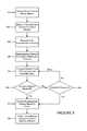
- FIG. 5illustrates an exemplary method for transmission packet flow in a system like that disclosed in FIG. 4 ;
- FIG. 6illustrates an exemplary transmission schedule comprising transmission attempt, physical later data rate, antenna configuration, and transmit power information
- FIG. 7illustrates an exemplary transmission schedule like that disclosed in FIG. 6 and further comprising yield on failure information
- FIG. 8illustrates a block diagram of an exemplary software layer, device driver, and a hardware layer of the system and for implementing reception parameter control, in accordance with one exemplary embodiment of the present invention.
- a system for a wireless (e.g., radio frequency or RF) link to a remote receiving devicein accordance with an embodiment of the present invention generally includes a communication device for generating an RF signal, an antenna apparatus with selectable antenna elements for transmitting and/or receiving the RF signal, and a processor for controlling the communication device and the antenna apparatus.
- the communication device(or a device communicatively coupled thereto) converts data packets into RF at one of a plurality of selectable physical data rates.
- Each antenna element of the antenna apparatusmay provide gain (with respect to an isotropic antenna) and a directional radiation pattern and may be electrically selected (e.g., switched on or off) so that the antenna apparatus may form a configurable (i.e., direction agile) radiation pattern.
- the processormay select the antenna configuration so that interference may be minimized in the wireless link to the remote receiving node.
- the processormay also select the physical data rate to maximize data transmission speed.
- the processormay select an antenna configuration with a resulting radiation pattern that minimizes the interference.
- the processormay also select an antenna configuration corresponding to a maximum gain between the system and the remote receiving device.
- the processormay select an antenna configuration corresponding to less than maximal gain but corresponding to reduced interference in the wireless link.
- the processormay select a physical data rate that maximizes data transmission speed (i.e., effective user data rate) over the wireless link to the remote receiving device.
- FIG. 1illustrates a system 100 comprising an antenna apparatus with selectable elements in accordance with one exemplary embodiment of the present invention.
- the system 100may comprise, for example, a transmitter and/or a receiver, and be embodied as an 802.11 access point, an 802.11 receiver, a set-top box, a laptop computer, a television, a PCMCIA card, a remote control, or a remote terminal such as a handheld gaming device.
- the system 100may comprise an access point for communicating with one or more remote receiving nodes over a wireless link, for example, in an 802.11 wireless network.
- the system 100may receive data from a router connected to a wide-area network such as the Internet (not shown) or any variety of local area networks (also not shown).
- the system 100may transmit the data to one or more remote receiving nodes (e.g., receiving nodes 130 A- 130 C).
- the system 100may also form a part of a wireless local area network (LAN) by enabling communications among two or more of the remote receiving nodes 130 A- 130 C.
- LANwireless local area network
- system 100may also comprise the remote receiving node 130 A. Further, the system 100 may also be implemented with regard to other wireless network standards (e.g., IEEE 802.x).
- IEEE 802.xIEEE 802.x
- System 100may include a communication device 120 (e.g., a transceiver) and an antenna apparatus 110 .
- the communication device 120may comprise virtually any device for converting data at a physical data rate and for generating and/or receiving a corresponding RF signal.
- the communication device 120may include, for example, a radio modulator/demodulator for converting data received by the system 100 (e.g., from a router) into the RF signal for transmission to one or more of the remote receiving nodes 130 A- 130 C.
- the communication device 120also comprises circuitry for receiving data packets of video from the router and circuitry for converting the data packets into 802.11 compliant RF signals.
- Various other hardware and/or software devices and/or elementsmay be integrated with communication device 120 (e.g., physical integration or a communicative coupling) as to allow for the processing and/or conversion of various other data formats into 802.11 compliant RF signals.
- the antenna apparatus 110may include a plurality of individually selectable antenna elements (not shown). When selected, each of the individual antenna elements produces a directional radiation pattern with gain (as compared to an omni-directional antenna).
- the antenna apparatus 110may further include an antenna element selector device 310 ( FIG. 3 ) to selectively couple one or more of the antenna elements to the communication device 120 .
- an antenna apparatus 110 and the antenna element selector device 310are disclosed in U.S.
- FIG. 2illustrates various radiation patterns resulting from selecting different antenna configurations of the antenna apparatus 110 of FIG. 1 in accordance with one exemplary embodiment of the present invention.
- the antenna apparatus 110 used to produce the exemplary radiation pattern of FIG. 2comprises four selectable antenna elements ⁇ A
- the antenna elements (referred to as antenna elements A-D) of the present exampleare offset from one other by 90 degrees.
- Each antenna element of the present exampleproduces a similar radiation pattern offset from the other radiation patterns (e.g., the radiation pattern of the antenna element A is offset by approximately 90 degrees from the radiation pattern of the antenna element B and so on). For clarity of explanation, only three exemplary radiation patterns are shown in FIG. 2 .
- a first radiation pattern 215is produced by selecting the antenna element A.
- the radiation patternis a generally cardioid pattern oriented with a center at about 315 degrees in azimuth.
- a second radiation pattern 205is produced by selecting the antenna element B.
- Antenna element Bis offset 90 degrees from antenna element A; the radiation pattern 205 is therefore oriented with a center at about 45 degrees in azimuth.
- a combined radiation pattern 210depicted as a bold line, results from the selection of antenna element A and antenna element B. It will be appreciated that by selecting one or more of the antenna elements A-D in FIG. 2 , fifteen radiation patterns can be produced by the antenna apparatus 110 .
- a substantially omni-directional radiation pattern that may be produced by selecting two or more of the antenna elements A-Dis not shown in FIG. 2 (for the sake of clarity). Notwithstanding, it will be appreciated that the antenna apparatus 110 may produce a range of radiation patterns, ranging from highly directional to omni-directional. Accordingly, these resulting radiation patterns are also referred as antenna configurations.
- FIG. 3illustrates an exemplary block diagram of the system 100 , in accordance with one exemplary embodiment of the present invention.
- the system 100may include a processor 320 coupled to a memory 330 .
- the processor 320may comprise a microcontroller, a microprocessor, or an application-specific integrated circuit (ASIC).
- the processor 320may be configured to execute programs stored in the memory 330 .
- the memory 330may also store transmission schedules, which may specify transmit instructions including physical layer transmission rates for the communication device 120 and antenna configurations for the antenna apparatus 110 .
- the transmissions schedulemay also include additional information such as transmit power.
- the transmission schedule(examples of which are illustrated in FIGS. 6 and 7 —may be embodied as a program for execution by low-level hardware or firmware.
- the transmission schedulemay also be embodied as a set of transmission metrics that allow for ‘tuning’ of transmission and retransmission processes in a more efficient manner.
- the processor 320may be further coupled to the antenna element selector device 310 by a control bus 340 .
- the antenna element selector device 310may be coupled to the aforementioned antenna apparatus 110 to allow, for example, selection from among the multiple radiation patterns described in FIG. 2 .
- the processor 320controls the antenna element selector device 310 to select an antenna configuration (i.e., one of the multiple radiation patterns) of the antenna apparatus 110 .
- the antenna selector device 310may accept and respond to information (instructions) related to a transmission schedule with regard to the selection of a particular antenna configuration (e.g., one of the aforementioned radiation patterns referenced in the context of FIG. 2 ).
- the processor 320is further coupled to the communication device 120 by the control bus 340 .
- the processor 320controls the communication device 120 to select a physical data rate (i.e., one of the multiple physical data rates).
- the processor 320controls the physical data rate at which the communication device 120 converts data bits into RF signals for transmission via the antenna apparatus 110 .
- the selection of a physical data ratemay be associated with a particular antenna configuration, and/or other transmission parameters (e.g., transmit power) in the context of a transmission schedule like those referenced in FIGS. 6 and 7 .
- the processor 320may receive packet data, Transmission Control Protocol (TCP) packet data, or User Datagram Protocol (UDP) packet data from an external local area network (LAN) 350 .
- the processor 320may convert the TCP or UDP packet data into an 802.11 wireless protocol.
- the processor 320may select an antenna configuration of the antenna apparatus 110 and sends the 802.11 wireless protocol to the communication device 120 for conversion at the physical data rate into RF for transmission via the antenna apparatus 110 to the remote receiving node (e.g., the remote receiving node 130 A) over the wireless link (e.g., the wireless link 140 A) in accordance with transmission parameters set forth in a particular transmission schedule.
- the remote receiving nodee.g., the remote receiving node 130 A
- the wireless linke.g., the wireless link 140 A
- An exemplary method executed by the processor 320 for selecting the antenna configurationmay comprise creating and/or accessing a table having transmission parameter control data for each remote receiving node 130 .
- the tablemay include link quality metrics for each antenna configuration. Some examples of link quality metrics are a success ratio, an effective user data rate, a received signal strength indicator (RSSI), and error vector magnitude (EVM) as are discussed in the context of U.S. patent application Ser. No. 11/180,329 (U.S. Pat. No. 7,899,497) and previously incorporated herein by reference.
- the processor 320may generate a table of success ratios for each antenna configuration using one or more link quality metrics. Each antenna configuration on the table may then be sorted using the corresponding success ratio. An antenna configuration can then be chosen from the sorted table. The table of success ratios can then be subsequently updated based on the outcome of the transmission.
- An additional exemplary method executed by processor 320may comprise querying transmission parameter control software for transmission parameters for a packet based on the packet destination address.
- the transmission parameter control softwaremay specify transmit instructions including physical layer transmission rates and antenna configurations—in the context of a transmission schedule.
- the processor 320may further modify or update a transmission schedule based on, for example, transmission attempt results as they pertain to a particular transmission schedule.
- FIG. 4illustrates a block diagram of an exemplary software layer 405 , a device driver 450 , and a hardware layer 455 , in accordance with one exemplary embodiment of the present invention.
- the software layer 405 and the device driver 450may comprise instructions executed by the processor 320 (in FIG. 3 ).
- the hardware layer 455may comprise hardware elements of the system 100 described with respect to FIG. 3 , such as the antenna selector device 310 and the communication device 120 .
- aspects of the inventionmay be implemented with any combination of software, hardware, and/or firmware elements.
- the software layer 405may include a transmission parameter control module 410 and a feedback module 420 .
- the feedback module 420may include a database 425 .
- the hardware layer 455may include transmitter 460 and receiver 465 .
- the transmission parameter control module 410may be linked to the feedback module 420 .
- the transmission parameter control module 410may communicate with the device driver 450 via link 430 .
- the feedback modulemay communicate with the device driver 450 via link 435 .
- the device driver 450may receive packets via link 440 from the software layer 405 and sends the packets to the transmitter 460 in the hardware layer 455 .
- the device driver 450may also receive packets from the receiver 465 in the hardware layer 455 and sends the packets to the software layer 405 via link 445 .
- the transmission parameter control module 410may comprise software elements configured to select for the device driver 450 the current antenna configuration and the current physical data rate based on the feedback module 420 .
- the transmission parameter control module 410may further comprise certain functionality as may be found in a transmission control selector like that disclosed in U.S. patent application Ser. No. 11/180,329 and previously incorporated herein by reference. Such a selector (and associated functionality) may be related to a probe scheduler.
- a probe schedulermay comprise software elements configured to determine for a transmission control selector an unused antenna configuration and an unused physical data rate based on predetermined criteria.
- One example of the predetermined criteriais determining an unused antenna configuration after the device driver 450 indicates as received 5 consecutive packets.
- the feedback module 420 of the present disclosuremay comprise software elements configured to update link quality metrics for each antenna configuration and each physical data rate based on feedback from the device driver 450 .
- the transmission parameter control module 470further provides transmission parameters for a packet based on the packet destination address.
- the transmission parameter control module 470provides a transmission schedule, which may be stored in database 425 of feedback module 420 or in a database dedicated to the control module 410 (not shown).
- the transmission schedulespecifies transmit instructions including physical layer transmission rates and antenna configurations.
- the transmission scheduleis delivered to the device driver 450 in response to, for example, a driver query upon receipt of a unicast packet from an upper network layer by the driver 450 .
- the driver 450provides the data packet and transmission schedule to the hardware layer 455 for transmission.
- the hardware layer 455may notify the driver 450 of the result of the transmission attempt, which is in turn reported to the transmission parameter control module 410 , the feedback module 420 , or both modules for the purpose of updating the database 425 , which may update a transmission schedule if deemed necessary.
- Certain functionality of the feedback module 420may, in some embodiments, be integrated with the transmission parameter control module 410 with regard to updating a database 425 of transmission schedules. In such an embodiment, the feedback module 420 may be configured to maintain a separate dedicated database of transmission schedules in addition to being configured to maintain the link quality metrics in the database 425 .
- the operation of the software layer 405 , the device driver 450 , and the hardware layer 455are further described below.
- the transmission parameter control module 410may select a transmission schedule comprising, for example, an antenna configuration for the antenna apparatus 110 that minimizes interference for communicating over the wireless link 140 A to the remote receiving node 130 A based on feedback (i.e., direct or indirect) from the receiving node, which may be reflected by an acknowledgment resulting from the transmission.
- the device driver 450may indicate whether the remote receiving node received transmitted packets on a particular antenna configuration and physical data rate.
- the transmission parameter control module 410may select another antenna configuration for communicating over the wireless link 140 B to the remote receiving node 130 B based on the lack of an acknowledgment and in accordance with a subsequent transmission schedule thereby changing the radiation pattern of the antenna apparatus 110 to minimize interference in the wireless link 140 A and/or the wireless link 140 B and/or to compensate for particular physical layer data rates.
- the transmission parameter control module 410may select the appropriate transmission schedule with an associated antenna configuration corresponding to a maximum gain for the wireless links 140 A- 140 C.
- the transmission parameter control module 410may select a transmission schedule wherein the antenna configuration corresponds to less than maximal gain but instead corresponds to reduced interference, in the wireless links 140 A- 140 C.
- transmission parameter control selection module 410may select an accompanying physical data rate that provides the maximum effective user data rate at the remote receiving node 130 A over the wireless link 140 A.
- the transmission schedule provided to the hardware layer 455 via device driver 450may be provided as part of a transmit descriptor allowing granulated control over transmission and retransmission processes in an efficient manner.
- the granulated control of transmission parameter control module 410may be integrated with the functionality of a transmission control selector or alternatively operate in conjunction with the same.
- FIG. 5illustrates an exemplary method for transmission packet flow 500 in a system like that disclosed in FIG. 4 ( 400 ).
- step 510directed unicast packets are sent to device driver 450 from upper network layers for transmission.
- step 520the driver 450 queries the transmission parameter control module 410 for transmission parameters for the packet based on a packet destination address.
- the transmission parameter selection module 410provides a transmission schedule (like those disclosed in FIGS. 6 and 7 below) in step 530 .
- the transmission schedulespecifies transmit instructions, including physical layer transmission rates and antenna configurations.
- the driver 450provides the data packet and transmission schedule to the wireless network interface, which (in exemplary embodiments) may be embodied in the hardware layer 455 .
- the wireless network interface of the hardware layer 455(for every N-th transmission attempt) transmits the packet using parameters from the N-th entry of the transmission schedule as illustrated in FIGS. 6 and 7 . If the network interface of the hardware layer 455 , in step 560 , fails to receive an 802.11 layer acknowledgment, a determination is made as to whether the transmission schedule has been exhausted in step 590 (i.e., the transmission attempt schedule has entries that have not yet been utilized).
- the network interface of the hardware layer 455will attempt to re-transmit the packet using parameters from a new entry of the transmission schedule (e.g., N+1) in a manner similar to the original transmission of step 550 .
- the network interface of the hardware layer 455will continue this cycle (steps 550 , 560 , 590 , and returning to 550 if appropriate) of utilizing a new entry of the transmission schedule until an 802.11 layer acknowledgement is received in step 560 or until the schedule is exhausted (i.e., no unused scheduling entries remain) in step 590 .
- step 560the present exemplary method proceeds to step 570 wherein the network interface of the hardware layer 455 informs the driver 450 of the results of the transmission attempt.
- the driver 450in turn, notifies the transmission parameter control module 410 of the aforementioned transmission results in step 580 . If an 802.11 layer acknowledgement is not received in step 560 and the schedule is exhausted (i.e., no unused scheduling entries remain) as determined in step 590 , the driver 450 is informed of the results in step 570 , which are, in turn, reported to the control module 920 in step 580 .
- FIG. 6illustrates an exemplary transmission schedule 600 comprising transmission attempt 610 , physical later data rate 620 , antenna configuration 630 and transmit power information 640 .
- transmission schedule 600may be stored in database 425 ( FIG. 4 ) for each packet destination address. Each destination address may require different antenna configurations and/or physical data rates for optimal performance of each of the wireless links ( 140 A-C), therefore multiple transmission schedules 600 may be developed and maintained. For ease of the present discussion, only a single transmission schedule 600 will be discussed.
- the feedback module 420may update the transmission schedule 600 with respect to, for example, antenna configuration or physical layer data rate (columns 620 and 630 ) after the device driver 450 (in FIG. 4 ) indicates a packet as having been transmitted to a packet destination address in light of receipt of an 802.11 layer acknowledgment.
- the feedback module 420may correlate a successful transmission rate (e.g., a success ratio) with respect to a particular physical data rate and antenna configuration on a particular transmission attempt for a particular packet destination address.
- link quality metricsmay be associated with the transmission schedule 600 and an associated set of transmission parameters for a packet based on packet destination address such as receive signal strength indication (RSSI), voltage standing wave ratio (VSWR), signal quality, bit error rate, and error vector magnitude (EVM).
- RSSIreceive signal strength indication
- VSWRvoltage standing wave ratio
- EVMerror vector magnitude
- Antenna configuration 630corresponds to the multiple antenna configurations of the antenna apparatus 110 .
- a table of transmission control data for an antenna apparatus 110 having four selectable antenna elements ⁇ A, B, C, D ⁇would have fifteen possible antenna configurations comprising the set ⁇ A
- Indicia of a particular configurationmay be associated with each one of the aforementioned configurations.
- the schedule 600may need only to comprise information related to transmission attempt 610 , data rate 620 , and antenna configuration 630 .
- Certain other informationsuch as transmit power 640 (e.g., the power ratio in decibels (dB) of the measured power referenced to one milliwatt (mW)), may be optional.
- transmit power 640e.g., the power ratio in decibels (dB) of the measured power referenced to one milliwatt (mW)
- dBdecibels
- mWmilliwatt
- the transmission schedule 600is a program for execution by the hardware or firmware disclosed in FIG. 4 .
- the schedule 600may be provided to the network interface of the hardware or firmware 455 for execution in step 540 as part of a transmit descriptor, which allows for the driver 450 to exercise fine grained control over the transmission and retransmission process in an efficient manner.
- the transmission schedule 700may be desirous for the transmission schedule 700 ( FIG. 7 ) to further comprise yield on failure information 750 in addition to the aforementioned transmission attempt 710 , physical layer data rate 720 , antenna configuration 730 , and transmit power 740 information.
- yield on failure information 750in addition to the aforementioned transmission attempt 710 , physical layer data rate 720 , antenna configuration 730 , and transmit power 740 information.
- the control offered by the presently disclosed system and associated transmission schedulesoffers functionality that may be referenced as a ‘smart antenna.’
- a ‘smart antennaThrough the aforementioned transmission schedules as they related to a particular packet destination, it becomes possible to precisely control the antenna configuration and related transmission minutia during packet transmission such that an antenna array may ‘point’ in the direction of the receiving station.
- the presently disclosed ‘smart antenna’may further allow for the selection of a subsequent antenna configuration corresponding to a next transmission of packet data being received from a particular station. In this way, under certain conditions (such as when a transmission link is idle), the difficulties associated with passively listening for an incoming transmission and associated configurations are diminished.
- Network protocolstend to be regular. As such, and through the use of one or more heuristic algorithms, it becomes possible to accurately predict the identity and/or location of a next transmitting station.
- the predictive results of the algorithmsmay themselves be embodied in a variety of schedules with respect to anticipated data packet reception.
- An exemplary prediction algorithmmay be based on a last transmission, which may be of particular use in—but is not limited to—a request/response data exchange or in those networks that have strong temporal locality.
- the receive antenna configurationis set based on the station to which the software-controlled smart antenna last transmitted.
- the receive antenna configuration‘follows’ the transmit antenna configuration. Accordingly, the antenna configuration that was used to transmit data to a particular destination address may be the same configuration used to receive data from that address. Alternatively, it may be determined that data received from a particular destination address is ideally received in a particular configuration. Accordingly, if data is transmitted to a particular destination address, the antenna will automatically be reconfigured for an optimized configuration associated with receipt of data from that particular address following the initial data transmission.
- Another exemplary prediction algorithmmay be based on packet pattern recognition.
- Many protocolssuch as transmission control protocol (TCP)
- TCPtransmission control protocol
- ACKTCP-level acknowledgment
- a packet pattern recognition algorithmmay be implemented such that, for each active flow, the number of transmitted packets that occur between received packets are counted.
- the ‘smart antenna’determines when an individual flow is expected for packet reception.
- the receive antennamay then be configured such that it corresponds to a station who's flow is ‘due.’
- a third exemplary prediction algorithmmay be based on an indication of a cyclic redundancy check (CRC) with respect to a serial transmission of data.
- CRCcyclic redundancy check
- a CRC for a block of datais calculated before the data is sent; the CRC on that block of data is sent along with the primary data transmission.
- a new CRCis calculated on the received data. If the pre-transmission CRC transmitted along with the primary block of data does not match the CRC performed after receipt of that data, then an error has occurred. For example, after a failed packet reception by the presently disclosed antenna, the hardware layer will notify the software of a CRC event.
- the packet data that was receivedis of sufficient quality that the source Media Access Control (MAC) (i.e., the unique 48-bit number used in Ethernet data packets to identify an Ethernet device, such as the base station) may be determined.
- the software of the presently disclosed antennamay then ‘look up’ the ‘best’ antenna configuration associated with the source MAC address and set the receive antenna configuration such that when the failed packet is retransmitted by the source, the packet will be received on the best antenna configuration for the station thereby possibly even alleviating the anomaly that resulted in the failed packet transmission in the first place.
- MACMedia Access Control
- a fourth exemplary prediction algorithmmay be based on temporal prediction as a number of data flows, such as voice and video, are temporarily periodic. By tracking packet inter arrival-times on a per-flow basis, the presently described antenna system may predict when in time a particular data flow will become active. A master schedule may then be compiled reflecting to activation times for particular active flows as they originate from a particular station. In such an embodiment, and in accordance with the master schedule, the receive antenna may be preemptively configured in advance of a particular flow from a particular locale at a particular time.
- a fifth exemplary prediction algorithmmay be based upon scheduled MAC.
- the 802.11 and 802.11e standardsthe latter of which enhances the IEEE 802.11 MAC layer, specify optional modes of operation wherein the presently described ‘smart antenna’ may provide scheduling functionality normally associated with Time-Division Multiplexing (TDM), such as Hybrid Coordination Function Controlled Channel Access (HCCA).
- TDMTime-Division Multiplexing
- HCCAHybrid Coordination Function Controlled Channel Access
- HCCAis similar in operation to Point Coordination Function, wherein access points or Wi-Fi adapters send beacon frames at a regular interval; in between these beacons a Distributed Coordination Function (DCF) or Contention Free-Poll (CF-Poll) packet function is implemented to control access to the transmission medium and/or to manage various QOS concerns.
- DCFDistributed Coordination Function
- CF-PollContention Free-Poll
- HCCAalso utilizes the interval between beacon frames to control access to the medium and/or to operate in Enhanced DCF Channel Access wherein high priority traffic has a higher chance of being sent than low priority traffic.
- traffic classessuch that traffic can be coordinated versus, for example, round-robin.
- the implementation of traffic classesalso allows for station priority and transmit opportunity (TXOP) such that a particular access point my send as many frames as possible in a particular window of time.
- TXOPstation priority and transmit opportunity
- the antennamay be preemptively configured such that its configuration is the optimal configuration depending on a particular station scheduled to commence a transmission.
- FIG. 8illustrates a block diagram of an exemplary software layer 805 , device driver 870 , and hardware layer 875 of the system and for implementing reception parameter control, in accordance with one exemplary embodiment of the present invention.
- Software layer 805 and device driver 870may comprise instructions executed by the processor 320 (in FIG. 3 ).
- the hardware layer 875may comprise hardware elements of the system 100 described with respect to FIG. 3 , such as the antenna selector device 310 , which is also depicted here as antenna element selector device 880 , which is in turn coupled to antenna apparatus 885 .
- antenna selector device 310which is also depicted here as antenna element selector device 880 , which is in turn coupled to antenna apparatus 885 .
- Master scheduling module 810may comprise one or more subsidiary modules, which in turn may execute specific antenna selection algorithms or be executed in conjunction with another antenna selection module to determine a best algorithm.
- the exemplary master scheduling module 810comprises a packet pattern recognition module 815 , a CRC module 820 , a scheduled MAC module 825 , a temporal prediction module 830 , and a last transmission module 835 .
- the particular algorithm executed by each of these subsidiary moduleshas been discussed above in greater detail.
- Master scheduling module 810may comprise each of these modules, a selection of these modules, or additional modules not necessarily discussed here. After a particular antenna configuration has been identified by an antenna selection module, the master scheduling module 820 communicates this selection to the device driver 870 , via link 850 , which in turn causes the selector device 880 to implement a particular antenna configuration in a receiver of antenna apparatus 885 . For example, processor 320 may cause the selector device 880 to select a particular configuration of antenna apparatus 110 in response to selection instructions received from scheduling module 810 .
- the particular selection of an antenna configurationmay be recorded in database 845 of feedback module 840 , which is coupled to the master scheduling module 810 .
- feedback as to the quality of the packet receptionmay also be provided to the feedback module 840 via device driver 870 and hardware layer 875 through link 855 .
- This feedback datamay be stored in database 845 and associated with the selection of that particular configuration as it pertains to certain network conditions, data conditions, and the like considered by the master scheduling module 810 and the responsible subsidiary module with regard to determining a particular antenna configuration to be used in the receipt of packet data.
- the feedback modulemay, over the course time, determine that particular modules may be more accurate with regard to the selection of a particular antenna configuration and, when a data transmission from a particular station is involved, cause the master scheduling module 810 to rely on a particular antenna configuration as determined by a particular module in order to more optimally select particular configurations.
- the feedback modulemay periodically causes the master scheduling module 810 to select a configuration identified by a non-regular module (e.g., CRC versus temporal) in order to obtain a more relevant sample of feedback data as it pertains to particular stations, particular configurations, and particular modules electing the particular configuration.
- a non-regular modulee.g., CRC versus temporal
- Such test samplingmay occur as part of a regular data reception or may be the result of the module causing the transmission and subsequent reception of reply data during idle time whereby a regularly scheduled or in-progress transmission is not interrupted or possibly subjected to a less than ideal antenna configuration.
Landscapes
- Engineering & Computer Science (AREA)
- Computer Networks & Wireless Communication (AREA)
- Signal Processing (AREA)
- Mobile Radio Communication Systems (AREA)
Abstract
Description
Claims (11)
Priority Applications (3)
| Application Number | Priority Date | Filing Date | Title |
|---|---|---|---|
| US12/545,796US9153876B2 (en) | 2004-08-18 | 2009-08-21 | Transmission and reception parameter control |
| US13/340,425US9484638B2 (en) | 2004-08-18 | 2011-12-29 | Transmission and reception parameter control |
| US15/338,246US10187307B2 (en) | 2004-08-18 | 2016-10-28 | Transmission and reception parameter control |
Applications Claiming Priority (11)
| Application Number | Priority Date | Filing Date | Title |
|---|---|---|---|
| US60315704P | 2004-08-18 | 2004-08-18 | |
| US60271104P | 2004-08-18 | 2004-08-18 | |
| US62533104P | 2004-11-05 | 2004-11-05 | |
| US63049904P | 2004-11-22 | 2004-11-22 | |
| US11/010,076US7292198B2 (en) | 2004-08-18 | 2004-12-09 | System and method for an omnidirectional planar antenna apparatus with selectable elements |
| US11/022,080US7193562B2 (en) | 2004-11-22 | 2004-12-23 | Circuit board having a peripheral antenna apparatus with selectable antenna elements |
| US11/041,145US7362280B2 (en) | 2004-08-18 | 2005-01-21 | System and method for a minimized antenna apparatus with selectable elements |
| US69369805P | 2005-06-23 | 2005-06-23 | |
| US11/180,329US7899497B2 (en) | 2004-08-18 | 2005-07-12 | System and method for transmission parameter control for an antenna apparatus with selectable elements |
| US11/474,057US7933628B2 (en) | 2004-08-18 | 2006-06-23 | Transmission and reception parameter control |
| US12/545,796US9153876B2 (en) | 2004-08-18 | 2009-08-21 | Transmission and reception parameter control |
Related Parent Applications (1)
| Application Number | Title | Priority Date | Filing Date |
|---|---|---|---|
| US11/474,057DivisionUS7933628B2 (en) | 2004-08-18 | 2006-06-23 | Transmission and reception parameter control |
Related Child Applications (1)
| Application Number | Title | Priority Date | Filing Date |
|---|---|---|---|
| US13/340,425DivisionUS9484638B2 (en) | 2004-08-18 | 2011-12-29 | Transmission and reception parameter control |
Publications (2)
| Publication Number | Publication Date |
|---|---|
| US20090310590A1 US20090310590A1 (en) | 2009-12-17 |
| US9153876B2true US9153876B2 (en) | 2015-10-06 |
Family
ID=46325647
Family Applications (6)
| Application Number | Title | Priority Date | Filing Date |
|---|---|---|---|
| US11/474,057Expired - Fee RelatedUS7933628B2 (en) | 2004-08-18 | 2006-06-23 | Transmission and reception parameter control |
| US12/545,796Expired - Fee RelatedUS9153876B2 (en) | 2004-08-18 | 2009-08-21 | Transmission and reception parameter control |
| US12/575,422Active2026-08-23US8594734B2 (en) | 2004-08-18 | 2009-10-07 | Transmission and reception parameter control |
| US13/282,157Expired - LifetimeUS8583183B2 (en) | 2004-08-18 | 2011-10-26 | Transmission and reception parameter control |
| US13/340,425Expired - Fee RelatedUS9484638B2 (en) | 2004-08-18 | 2011-12-29 | Transmission and reception parameter control |
| US15/338,246Expired - LifetimeUS10187307B2 (en) | 2004-08-18 | 2016-10-28 | Transmission and reception parameter control |
Family Applications Before (1)
| Application Number | Title | Priority Date | Filing Date |
|---|---|---|---|
| US11/474,057Expired - Fee RelatedUS7933628B2 (en) | 2004-08-18 | 2006-06-23 | Transmission and reception parameter control |
Family Applications After (4)
| Application Number | Title | Priority Date | Filing Date |
|---|---|---|---|
| US12/575,422Active2026-08-23US8594734B2 (en) | 2004-08-18 | 2009-10-07 | Transmission and reception parameter control |
| US13/282,157Expired - LifetimeUS8583183B2 (en) | 2004-08-18 | 2011-10-26 | Transmission and reception parameter control |
| US13/340,425Expired - Fee RelatedUS9484638B2 (en) | 2004-08-18 | 2011-12-29 | Transmission and reception parameter control |
| US15/338,246Expired - LifetimeUS10187307B2 (en) | 2004-08-18 | 2016-10-28 | Transmission and reception parameter control |
Country Status (1)
| Country | Link |
|---|---|
| US (6) | US7933628B2 (en) |
Cited By (3)
| Publication number | Priority date | Publication date | Assignee | Title |
|---|---|---|---|---|
| US9344161B2 (en) | 2004-12-09 | 2016-05-17 | Ruckus Wireless, Inc. | Coverage enhancement using dynamic antennas and virtual access points |
| US9484638B2 (en) | 2004-08-18 | 2016-11-01 | Ruckus Wireless, Inc. | Transmission and reception parameter control |
| US9780813B2 (en) | 2006-08-18 | 2017-10-03 | Ruckus Wireless, Inc. | Closed-loop automatic channel selection |
Families Citing this family (53)
| Publication number | Priority date | Publication date | Assignee | Title |
|---|---|---|---|---|
| US7292198B2 (en) | 2004-08-18 | 2007-11-06 | Ruckus Wireless, Inc. | System and method for an omnidirectional planar antenna apparatus with selectable elements |
| US7193562B2 (en) | 2004-11-22 | 2007-03-20 | Ruckus Wireless, Inc. | Circuit board having a peripheral antenna apparatus with selectable antenna elements |
| US7358912B1 (en) | 2005-06-24 | 2008-04-15 | Ruckus Wireless, Inc. | Coverage antenna apparatus with selectable horizontal and vertical polarization elements |
| US7893882B2 (en) | 2007-01-08 | 2011-02-22 | Ruckus Wireless, Inc. | Pattern shaping of RF emission patterns |
| US8340115B2 (en)* | 2005-06-29 | 2012-12-25 | Intel Corporation | Apparatus and method for combined rate and TX antenna selection mechanism |
| US7583649B1 (en)* | 2005-08-12 | 2009-09-01 | Marvell International Ltd. | Rate adaptation |
| US7970433B2 (en) | 2007-06-08 | 2011-06-28 | Modu Ltd. | SD switch box in a cellular handset |
| US10027789B2 (en) | 2007-02-13 | 2018-07-17 | Google Llc | Modular wireless communicator |
| US8391921B2 (en) | 2007-02-13 | 2013-03-05 | Google Inc. | Modular wireless communicator |
| JP5025356B2 (en)* | 2007-07-10 | 2012-09-12 | キヤノン株式会社 | COMMUNICATION SYSTEM, INFORMATION PROCESSING DEVICE, AND COMMUNICATION CONTROL METHOD |
| WO2009100568A1 (en)* | 2008-01-30 | 2009-08-20 | Zte Corporation | User terminal device and network accessing method used for it |
| US9450711B2 (en)* | 2008-04-02 | 2016-09-20 | Qualcomm Incorporated | Method and apparatus for extended reverse direction grant in a wireless local area network (WLAN) |
| US10771199B2 (en) | 2008-04-02 | 2020-09-08 | Qualcomm Incorporated | Methods and apparatus for reverse link acknowledgement in a wireless local area network (WLAN) |
| US9203560B2 (en) | 2008-04-04 | 2015-12-01 | Qualcomm Incorporated | Methods and apparatus for delayed block acknowledgement in a wireless local area network (WLAN) |
| US8412226B2 (en)* | 2008-06-24 | 2013-04-02 | Google Inc. | Mobile phone locator |
| US8217843B2 (en) | 2009-03-13 | 2012-07-10 | Ruckus Wireless, Inc. | Adjustment of radiation patterns utilizing a position sensor |
| US20100302991A1 (en)* | 2009-06-02 | 2010-12-02 | Qualcomm Incorporated | System and process for transmit diversity in satellite phones |
| TWI466564B (en)* | 2009-07-16 | 2014-12-21 | Realtek Semiconductor Corp | Apparatus and method for adjusting transmission power of communication system |
| TWI607662B (en)* | 2009-07-16 | 2017-12-01 | 瑞昱半導體股份有限公司 | Apparatus and method for adjusting transmission power of communication system |
| US20110085504A1 (en)* | 2009-10-14 | 2011-04-14 | Chia-Chin Chong | Adaptive beam-forming and space-frequency block coding transmission scheme for mimo-ofdma systems |
| US8892142B2 (en)* | 2010-02-15 | 2014-11-18 | Telefonaktiebolaget L M Ericsson (Publ) | Methods and nodes in a communication system |
| US8185120B2 (en) | 2010-03-26 | 2012-05-22 | Microsoft Corporation | Cellular service with improved service availability |
| US9232473B2 (en) | 2011-07-10 | 2016-01-05 | Qualcomm Incorporated | Systems and methods for low-overhead wireless beacon timing |
| US9642171B2 (en) | 2011-07-10 | 2017-05-02 | Qualcomm Incorporated | Systems and methods for low-overhead wireless beacons having compressed network identifiers |
| US9253808B2 (en) | 2011-07-10 | 2016-02-02 | Qualcomm Incorporated | Systems and methods for low-overhead wireless beacons having next full beacon indications |
| US9167609B2 (en)* | 2011-07-10 | 2015-10-20 | Qualcomm Incorporated | Systems and methods for low-overhead wireless beacon timing |
| US8422540B1 (en) | 2012-06-21 | 2013-04-16 | CBF Networks, Inc. | Intelligent backhaul radio with zero division duplexing |
| US8467363B2 (en) | 2011-08-17 | 2013-06-18 | CBF Networks, Inc. | Intelligent backhaul radio and antenna system |
| CN102545978B (en)* | 2011-12-31 | 2014-10-29 | 福建星网锐捷网络有限公司 | Intelligent antenna configuration method, intelligent antenna system and wireless access equipment |
| US8756668B2 (en) | 2012-02-09 | 2014-06-17 | Ruckus Wireless, Inc. | Dynamic PSK for hotspots |
| US10186750B2 (en) | 2012-02-14 | 2019-01-22 | Arris Enterprises Llc | Radio frequency antenna array with spacing element |
| US9634403B2 (en) | 2012-02-14 | 2017-04-25 | Ruckus Wireless, Inc. | Radio frequency emission pattern shaping |
| US20130243064A1 (en)* | 2012-03-19 | 2013-09-19 | Mediatek Singapore Pte. Ltd. | Expert antenna control system |
| US20150271787A1 (en)* | 2012-03-19 | 2015-09-24 | Mediatek Singapore Pte. Ltd. | Expert antenna control system |
| US9092610B2 (en) | 2012-04-04 | 2015-07-28 | Ruckus Wireless, Inc. | Key assignment for a brand |
| US9026161B2 (en) | 2012-04-19 | 2015-05-05 | Raytheon Company | Phased array antenna having assignment based control and related techniques |
| CN102868431B (en)* | 2012-06-15 | 2015-06-17 | 福建星网锐捷网络有限公司 | Intelligent antenna control system and packet transmission method |
| US8842764B2 (en) | 2012-12-14 | 2014-09-23 | Telefonaktiebolaget L M Ericsson (Publ) | Precoder weight selection for MIMO communications when multiplicative noise limited |
| US8891657B2 (en) | 2012-12-14 | 2014-11-18 | Telefonaktiebolaget L M Ericsson(Publ) | Transmission power distribution for MIMO communications when multiplicative noise limited |
| US8831127B2 (en)* | 2012-12-14 | 2014-09-09 | Telefonaktiebolaget L M Ericsson (Publ) | Antenna reconfiguration for MIMO communications when multiplicative noise limited |
| CN104144516B (en) | 2013-05-10 | 2018-02-06 | 华为技术有限公司 | Wireless local network connecting point dispatching method, controller, access point and system |
| ES2875954T3 (en) | 2013-07-11 | 2021-11-11 | Andrew Wireless Systems Gmbh | Small cellular network architecture for the service of multiple network operators |
| EP3170269B1 (en) | 2014-07-15 | 2019-03-13 | ARRIS Enterprises LLC | Schedule aggregation and antenna-radiation-pattern optimization |
| US10447452B2 (en)* | 2015-07-13 | 2019-10-15 | Advanced Micro Devices, Inc. | Hardware controlled receive response generation |
| US10880224B1 (en) | 2016-01-12 | 2020-12-29 | Sprint Spectrum L.P. | Method and apparatus for selecting a voice coding rate based on the air interface efficiency of the serving base station |
| JP6483635B2 (en) | 2016-03-16 | 2019-03-13 | 株式会社東芝 | Wireless communication apparatus and wireless communication method |
| US20180006753A1 (en)* | 2016-07-01 | 2018-01-04 | Intel Corporation | Group addressed transmission techniques for directional wireless networks |
| US11196611B1 (en)* | 2017-08-24 | 2021-12-07 | National Technology & Engineering Solutions Of Sandia, Llc | Systems and methods for electronic communication with a device using an unknown communications protocol |
| US11109309B2 (en)* | 2019-03-29 | 2021-08-31 | Blackberry Limited | Systems and methods for establishing short-range communication links between asset tracking devices |
| US11121953B2 (en) | 2019-06-11 | 2021-09-14 | Arris Enterprises Llc | Access point performance monitoring and anomaly detection based on temporal and spatial anomalies |
| IL293723A (en) | 2020-03-12 | 2022-08-01 | Kyocera Avx Components San Diego Inc | System and method for removing channel quality indicator (cqi) data associated with a multimode antenna |
| US11509373B2 (en) | 2020-09-11 | 2022-11-22 | KYOCERA AVX Components (San Diego), Inc. | System and method for configuring a multi-mode antenna based on network performance indicators for a wireless network |
| US11722412B1 (en) | 2020-09-28 | 2023-08-08 | Amazon Technologies, Inc. | Dynamically managing connection parameters among multiple computing devices |
Citations (213)
| Publication number | Priority date | Publication date | Assignee | Title |
|---|---|---|---|---|
| US4027307A (en) | 1972-12-22 | 1977-05-31 | Litchstreet Co. | Collision avoidance/proximity warning system using secondary radar |
| US4176356A (en) | 1977-06-27 | 1979-11-27 | Motorola, Inc. | Directional antenna system including pattern control |
| US4193077A (en) | 1977-10-11 | 1980-03-11 | Avnet, Inc. | Directional antenna system with end loaded crossed dipoles |
| US4253193A (en) | 1977-11-05 | 1981-02-24 | The Marconi Company Limited | Tropospheric scatter radio communication systems |
| US4305052A (en) | 1978-12-22 | 1981-12-08 | Thomson-Csf | Ultra-high-frequency diode phase shifter usable with electronically scanning antenna |
| US4513412A (en) | 1983-04-25 | 1985-04-23 | At&T Bell Laboratories | Time division adaptive retransmission technique for portable radio telephones |
| US4641304A (en)* | 1986-06-06 | 1987-02-03 | Rca Corporation | Announced retransmission random access system |
| US4814777A (en) | 1987-07-31 | 1989-03-21 | Raytheon Company | Dual-polarization, omni-directional antenna system |
| US5097484A (en) | 1988-10-12 | 1992-03-17 | Sumitomo Electric Industries, Ltd. | Diversity transmission and reception method and equipment |
| US5173711A (en) | 1989-11-27 | 1992-12-22 | Kokusai Denshin Denwa Kabushiki Kaisha | Microstrip antenna for two-frequency separate-feeding type for circularly polarized waves |
| EP0534612A2 (en) | 1991-08-28 | 1993-03-31 | Motorola, Inc. | Cellular system sharing of logical channels |
| US5203010A (en) | 1990-11-13 | 1993-04-13 | Motorola, Inc. | Radio telephone system incorporating multiple time periods for communication transfer |
| US5220340A (en) | 1992-04-29 | 1993-06-15 | Lotfollah Shafai | Directional switched beam antenna |
| US5373548A (en) | 1991-01-04 | 1994-12-13 | Thomson Consumer Electronics, Inc. | Out-of-range warning system for cordless telephone |
| US5408465A (en) | 1993-06-21 | 1995-04-18 | Hewlett-Packard Company | Flexible scheme for admission control of multimedia streams on integrated networks |
| EP0352787B1 (en) | 1988-07-28 | 1995-05-10 | Motorola, Inc. | High bit rate communication system for overcoming multipath |
| US5453752A (en) | 1991-05-03 | 1995-09-26 | Georgia Tech Research Corporation | Compact broadband microstrip antenna |
| US5507035A (en) | 1993-04-30 | 1996-04-09 | International Business Machines Corporation | Diversity transmission strategy in mobile/indoor cellula radio communications |
| US5559800A (en) | 1994-01-19 | 1996-09-24 | Research In Motion Limited | Remote control of gateway functions in a wireless data communication network |
| US5697066A (en) | 1996-03-07 | 1997-12-09 | The Trustees Of Columbia University | Media access protocol for packet access within a radio cell |
| US5754145A (en) | 1995-08-23 | 1998-05-19 | U.S. Philips Corporation | Printed antenna |
| US5767809A (en) | 1996-03-07 | 1998-06-16 | Industrial Technology Research Institute | OMNI-directional horizontally polarized Alford loop strip antenna |
| US5802312A (en) | 1994-09-27 | 1998-09-01 | Research In Motion Limited | System for transmitting data files between computers in a wireless environment utilizing a file transfer agent executing on host system |
| US5940771A (en) | 1991-05-13 | 1999-08-17 | Norand Corporation | Network supporting roaming, sleeping terminals |
| US5964830A (en) | 1995-08-22 | 1999-10-12 | Durrett; Charles M. | User portal device for the world wide web to communicate with a website server |
| US6005525A (en) | 1997-04-11 | 1999-12-21 | Nokia Mobile Phones Limited | Antenna arrangement for small-sized radio communication devices |
| US6034638A (en) | 1993-05-27 | 2000-03-07 | Griffith University | Antennas for use in portable communications devices |
| US6094177A (en) | 1997-11-27 | 2000-07-25 | Yamamoto; Kiyoshi | Planar radiation antenna elements and omni directional antenna using such antenna elements |
| US6169888B1 (en) | 1996-02-24 | 2001-01-02 | Fuba Automotive Gmbh | Receiving antenna scanning diversity system with controllable switching |
| JP2001057560A (en) | 1999-08-18 | 2001-02-27 | Hitachi Kokusai Electric Inc | Wireless LAN system |
| US6249216B1 (en) | 1996-08-22 | 2001-06-19 | Kenneth E. Flick | Vehicle security system including adaptor for data communications bus and related methods |
| US6266537B1 (en) | 1998-03-27 | 2001-07-24 | Nec Corporation | Radio communication system |
| US6266528B1 (en) | 1998-12-23 | 2001-07-24 | Arraycomm, Inc. | Performance monitor for antenna arrays |
| US20010012764A1 (en) | 1996-10-15 | 2001-08-09 | Keith Russell Edwards | Fixed wireless access channel radio communication system |
| US6288682B1 (en) | 1996-03-14 | 2001-09-11 | Griffith University | Directional antenna assembly |
| US6292153B1 (en) | 1999-08-27 | 2001-09-18 | Fantasma Network, Inc. | Antenna comprising two wideband notch regions on one coplanar substrate |
| US6307524B1 (en) | 2000-01-18 | 2001-10-23 | Core Technology, Inc. | Yagi antenna having matching coaxial cable and driven element impedances |
| US6317599B1 (en) | 1999-05-26 | 2001-11-13 | Wireless Valley Communications, Inc. | Method and system for automated optimization of antenna positioning in 3-D |
| US6326922B1 (en) | 2000-06-29 | 2001-12-04 | Worldspace Corporation | Yagi antenna coupled with a low noise amplifier on the same printed circuit board |
| US6337668B1 (en) | 1999-03-05 | 2002-01-08 | Matsushita Electric Industrial Co., Ltd. | Antenna apparatus |
| US6337628B2 (en) | 1995-02-22 | 2002-01-08 | Ntp, Incorporated | Omnidirectional and directional antenna assembly |
| US6339404B1 (en) | 1999-08-13 | 2002-01-15 | Rangestar Wirless, Inc. | Diversity antenna system for lan communication system |
| US6345043B1 (en) | 1998-07-06 | 2002-02-05 | National Datacomm Corporation | Access scheme for a wireless LAN station to connect an access point |
| US6356242B1 (en) | 2000-01-27 | 2002-03-12 | George Ploussios | Crossed bent monopole doublets |
| US6356905B1 (en) | 1999-03-05 | 2002-03-12 | Accenture Llp | System, method and article of manufacture for mobile communication utilizing an interface support framework |
| US6356243B1 (en) | 2000-07-19 | 2002-03-12 | Logitech Europe S.A. | Three-dimensional geometric space loop antenna |
| US20020031130A1 (en) | 2000-05-30 | 2002-03-14 | Kazuaki Tsuchiya | Multicast routing method and an apparatus for routing a multicast packet |
| WO2002025967A1 (en) | 2000-09-22 | 2002-03-28 | Widcomm Inc. | Wireless network and method for providing improved handoff performance |
| US6377227B1 (en) | 1999-04-28 | 2002-04-23 | Superpass Company Inc. | High efficiency feed network for antennas |
| US20020047800A1 (en) | 1998-09-21 | 2002-04-25 | Tantivy Communications, Inc. | Adaptive antenna for use in same frequency networks |
| US6392610B1 (en) | 1999-10-29 | 2002-05-21 | Allgon Ab | Antenna device for transmitting and/or receiving RF waves |
| US6404386B1 (en) | 1998-09-21 | 2002-06-11 | Tantivy Communications, Inc. | Adaptive antenna for use in same frequency networks |
| US6407719B1 (en) | 1999-07-08 | 2002-06-18 | Atr Adaptive Communications Research Laboratories | Array antenna |
| US20020080767A1 (en) | 2000-12-22 | 2002-06-27 | Ji-Woong Lee | Method of supporting small group multicast in mobile IP |
| US20020084942A1 (en) | 2001-01-03 | 2002-07-04 | Szu-Nan Tsai | Pcb dipole antenna |
| US20020105471A1 (en) | 2000-05-24 | 2002-08-08 | Suguru Kojima | Directional switch antenna device |
| US20020112058A1 (en) | 2000-12-01 | 2002-08-15 | Microsoft Corporation | Peer networking host framework and hosting API |
| US6442507B1 (en) | 1998-12-29 | 2002-08-27 | Wireless Communications, Inc. | System for creating a computer model and measurement database of a wireless communication network |
| US20020119757A1 (en) | 2001-02-28 | 2002-08-29 | Kojiro Hamabe | Mobile communication system and transmission mode switching method used therefor as well as recording medium having program of the same method recorded therein |
| US6445688B1 (en) | 2000-08-31 | 2002-09-03 | Ricochet Networks, Inc. | Method and apparatus for selecting a directional antenna in a wireless communication system |
| US20020142744A1 (en) | 2001-03-28 | 2002-10-03 | Nec Corporation | Device and method for alerting user to interference |
| US20020158801A1 (en) | 2001-04-27 | 2002-10-31 | Crilly William J. | Wireless packet switched communication systems and networks using adaptively steered antenna arrays |
| US20020158798A1 (en) | 2001-04-30 | 2002-10-31 | Bing Chiang | High gain planar scanned antenna array |
| US20020170064A1 (en) | 2001-05-11 | 2002-11-14 | Monroe David A. | Portable, wireless monitoring and control station for use in connection with a multi-media surveillance system having enhanced notification functions |
| US6493679B1 (en) | 1999-05-26 | 2002-12-10 | Wireless Valley Communications, Inc. | Method and system for managing a real time bill of materials |
| US6492957B2 (en) | 2000-12-18 | 2002-12-10 | Juan C. Carillo, Jr. | Close-proximity radiation detection device for determining radiation shielding device effectiveness and a method therefor |
| US6496504B1 (en)* | 1998-08-06 | 2002-12-17 | Ricoh Company, Ltd. | Smart allocation of bandwidth for multiple independent calls on a digital network |
| US6499006B1 (en) | 1999-07-14 | 2002-12-24 | Wireless Valley Communications, Inc. | System for the three-dimensional display of wireless communication system performance |
| US6498589B1 (en) | 1999-03-18 | 2002-12-24 | Dx Antenna Company, Limited | Antenna system |
| US6507321B2 (en) | 2000-05-26 | 2003-01-14 | Sony International (Europe) Gmbh | V-slot antenna for circular polarization |
| US20030026240A1 (en) | 2001-07-23 | 2003-02-06 | Eyuboglu M. Vedat | Broadcasting and multicasting in wireless communication |
| US20030030588A1 (en) | 2001-08-10 | 2003-02-13 | Music Sciences, Inc. | Antenna system |
| US20030038698A1 (en) | 2001-08-24 | 2003-02-27 | Sos From The Earth Inc. & Sun Tech., Co., Ltd. | Card-type apparatus and method for generating zero magnetic field |
| US20030063591A1 (en) | 2001-10-03 | 2003-04-03 | Leung Nikolai K.N. | Method and apparatus for data packet transport in a wireless communication system using an internet protocol |
| US20030122714A1 (en) | 2001-11-16 | 2003-07-03 | Galtronics Ltd. | Variable gain and variable beamwidth antenna (the hinged antenna) |
| US6606059B1 (en) | 2000-08-28 | 2003-08-12 | Intel Corporation | Antenna for nomadic wireless modems |
| US20030162551A1 (en) | 2002-02-21 | 2003-08-28 | Ntt Docomo, Inc. | Transmission control apparatus and transmission control method |
| US20030172114A1 (en) | 2001-10-24 | 2003-09-11 | Leung Nikolai K. N. | Method and apparatus for data packet transport in a wireless communication system using an internet protocol |
| US20030169330A1 (en) | 2001-10-24 | 2003-09-11 | Microsoft Corporation | Network conference recording system and method including post-conference processing |
| US6625454B1 (en) | 2000-08-04 | 2003-09-23 | Wireless Valley Communications, Inc. | Method and system for designing or deploying a communications network which considers frequency dependent effects |
| US20030184490A1 (en) | 2002-03-26 | 2003-10-02 | Raiman Clifford E. | Sectorized omnidirectional antenna |
| US20030189514A1 (en) | 2001-09-06 | 2003-10-09 | Kentaro Miyano | Array antenna apparatus |
| US20030189521A1 (en) | 2002-04-05 | 2003-10-09 | Atsushi Yamamoto | Directivity controllable antenna and antenna unit using the same |
| US20030189523A1 (en) | 2002-04-09 | 2003-10-09 | Filtronic Lk Oy | Antenna with variable directional pattern |
| US20030210207A1 (en) | 2002-02-08 | 2003-11-13 | Seong-Youp Suh | Planar wideband antennas |
| US20030227880A1 (en)* | 2002-06-10 | 2003-12-11 | Tantivy Communications, Inc. | Applying session services based on packet flows |
| US20030228857A1 (en) | 2002-06-06 | 2003-12-11 | Hitachi, Ltd. | Optimum scan for fixed-wireless smart antennas |
| US20030227414A1 (en) | 2002-03-04 | 2003-12-11 | Saliga Stephen V. | Diversity antenna for UNII access point |
| US20040008614A1 (en) | 2002-01-28 | 2004-01-15 | Kabushiki Kaisha Toshiba | Signal selection systems |
| WO2003079484A3 (en) | 2002-03-15 | 2004-01-22 | Andrew Corp | Antenna interface protocol |
| US20040014432A1 (en) | 2000-03-23 | 2004-01-22 | U.S. Philips Corporation | Antenna diversity arrangement |
| US20040017310A1 (en) | 2002-07-24 | 2004-01-29 | Sarah Vargas-Hurlston | Position optimized wireless communication |
| US20040017860A1 (en) | 2002-07-29 | 2004-01-29 | Jung-Tao Liu | Multiple antenna system for varying transmission streams |
| US20040027304A1 (en) | 2001-04-30 | 2004-02-12 | Bing Chiang | High gain antenna for wireless applications |
| US20040027291A1 (en) | 2002-05-24 | 2004-02-12 | Xin Zhang | Planar antenna and array antenna |
| US20040032378A1 (en) | 2001-10-31 | 2004-02-19 | Vladimir Volman | Broadband starfish antenna and array thereof |
| US20040032872A1 (en)* | 2002-08-13 | 2004-02-19 | Corona Networks, Inc. | Flow based dynamic load balancing for cost effective switching systems |
| US20040036651A1 (en) | 2002-06-05 | 2004-02-26 | Takeshi Toda | Adaptive antenna unit and terminal equipment |
| US20040036654A1 (en) | 2002-08-21 | 2004-02-26 | Steve Hsieh | Antenna assembly for circuit board |
| US6701522B1 (en) | 2000-04-07 | 2004-03-02 | Danger, Inc. | Apparatus and method for portal device authentication |
| US20040041732A1 (en) | 2001-10-03 | 2004-03-04 | Masayoshi Aikawa | Multielement planar antenna |
| US20040048593A1 (en) | 2000-12-21 | 2004-03-11 | Hiroyasu Sano | Adaptive antenna receiver |
| US20040047296A1 (en)* | 2002-03-08 | 2004-03-11 | Aware, Inc. | Systems and methods for high rate OFDM communications |
| US20040058690A1 (en) | 2000-11-20 | 2004-03-25 | Achim Ratzel | Antenna system |
| US20040061653A1 (en) | 2002-09-26 | 2004-04-01 | Andrew Corporation | Dynamically variable beamwidth and variable azimuth scanning antenna |
| US20040070543A1 (en) | 2002-10-15 | 2004-04-15 | Kabushiki Kaisha Toshiba | Antenna structure for electronic device with wireless communication unit |
| US6725281B1 (en) | 1999-06-11 | 2004-04-20 | Microsoft Corporation | Synchronization of controlled device state using state table and eventing in data-driven remote device control model |
| US20040080455A1 (en) | 2002-10-23 | 2004-04-29 | Lee Choon Sae | Microstrip array antenna |
| US20040082356A1 (en) | 2002-10-25 | 2004-04-29 | Walton J. Rodney | MIMO WLAN system |
| US20040095278A1 (en) | 2001-12-28 | 2004-05-20 | Hideki Kanemoto | Multi-antenna apparatus multi-antenna reception method, and multi-antenna transmission method |
| US20040114535A1 (en) | 2002-09-30 | 2004-06-17 | Tantivy Communications, Inc. | Method and apparatus for antenna steering for WLAN |
| US6753814B2 (en) | 2002-06-27 | 2004-06-22 | Harris Corporation | Dipole arrangements using dielectric substrates of meta-materials |
| US20040125777A1 (en) | 2001-05-24 | 2004-07-01 | James Doyle | Method and apparatus for affiliating a wireless device with a wireless local area network |
| US20040132496A1 (en) | 2003-01-04 | 2004-07-08 | Yun-Hee Kim | Adaptive transmission and receiving method and device in wireless communication system with multiple antennas |
| US6762723B2 (en) | 2002-11-08 | 2004-07-13 | Motorola, Inc. | Wireless communication device having multiband antenna |
| US20040162115A1 (en) | 2003-02-14 | 2004-08-19 | Martin Smith | Wireless antennas, networks, methods, software, and services |
| EP1450521A2 (en) | 2003-02-19 | 2004-08-25 | Nec Corporation | Wireless communication system and method which improves reliability and throughput of communication through retransmission timeout optimization |
| US20040165563A1 (en) | 2003-02-24 | 2004-08-26 | Hsu Raymond T. | Wireless local access network system detection and selection |
| US20040190477A1 (en) | 2003-03-28 | 2004-09-30 | Olson Jonathan P. | Dynamic wireless network |
| US6819287B2 (en) | 2002-03-15 | 2004-11-16 | Centurion Wireless Technologies, Inc. | Planar inverted-F antenna including a matching network having transmission line stubs and capacitor/inductor tank circuits |
| US20040260800A1 (en) | 1999-06-11 | 2004-12-23 | Microsoft Corporation | Dynamic self-configuration for ad hoc peer networking |
| US20050032531A1 (en) | 2003-08-06 | 2005-02-10 | Hong Kong Applied Science And Technology Research Institute Co., Ltd. | Location positioning in wireless networks |
| US20050041739A1 (en) | 2001-04-28 | 2005-02-24 | Microsoft Corporation | System and process for broadcast and communication with very low bit-rate bi-level or sketch video |
| US20050042988A1 (en) | 2003-08-18 | 2005-02-24 | Alcatel | Combined open and closed loop transmission diversity system |
| US20050053164A1 (en) | 2003-07-09 | 2005-03-10 | Severine Catreux | System and method for RF signal combining and adaptive bit loading for data rate maximization in multi-antenna communication systems |
| US6876280B2 (en) | 2002-06-24 | 2005-04-05 | Murata Manufacturing Co., Ltd. | High-frequency switch, and electronic device using the same |
| US20050074108A1 (en) | 1995-04-21 | 2005-04-07 | Dezonno Anthony J. | Method and system for establishing voice communications using a computer network |
| US20050074018A1 (en) | 1999-06-11 | 2005-04-07 | Microsoft Corporation | XML-based template language for devices and services |
| US20050083852A1 (en) | 2001-01-19 | 2005-04-21 | Ari Alastalo | Apparatus, and associated method, for utilizing antenna information determinative of antenna operation in a wireless mesh network |
| US6888504B2 (en) | 2002-02-01 | 2005-05-03 | Ipr Licensing, Inc. | Aperiodic array antenna |
| US6888893B2 (en) | 2001-01-05 | 2005-05-03 | Microsoft Corporation | System and process for broadcast and communication with very low bit-rate bi-level or sketch video |
| US6906678B2 (en) | 2002-09-24 | 2005-06-14 | Gemtek Technology Co. Ltd. | Multi-frequency printed antenna |
| US20050128988A1 (en) | 2003-09-30 | 2005-06-16 | Simpson Floyd D. | Enhanced passive scanning |
| US20050138137A1 (en) | 2003-12-19 | 2005-06-23 | Microsoft Corporation | Using parameterized URLs for retrieving resource content items |
| US20050138193A1 (en) | 2003-12-19 | 2005-06-23 | Microsoft Corporation | Routing of resource information in a network |
| US20050148306A1 (en) | 2004-01-05 | 2005-07-07 | Hiddink Gerrit W. | Predictive method and apparatus for antenna selection in a wireless communication system |
| US20050153658A1 (en) | 2004-01-12 | 2005-07-14 | Nagy Louis L. | Multiplexed self-structuring antenna system |
| US6924768B2 (en) | 2002-05-23 | 2005-08-02 | Realtek Semiconductor Corp. | Printed antenna structure |
| US6931429B2 (en) | 2001-04-27 | 2005-08-16 | Left Gate Holdings, Inc. | Adaptable wireless proximity networking |
| US20050180381A1 (en) | 2004-02-12 | 2005-08-18 | Retzer Michael H. | Method and apparatus for improving throughput in a wireless local area network |
| US20050185707A1 (en) | 2004-02-24 | 2005-08-25 | Hoo Min C. | Method and system for antenna selection diversity with minimum threshold |
| US20050188193A1 (en) | 2004-02-20 | 2005-08-25 | Microsoft Corporation | Secure network channel |
| US6941143B2 (en) | 2002-08-29 | 2005-09-06 | Thomson Licensing, S.A. | Automatic channel selection in a radio access network |
| US6950019B2 (en) | 2000-12-07 | 2005-09-27 | Raymond Bellone | Multiple-triggering alarm system by transmitters and portable receiver-buzzer |
| US6961573B1 (en) | 2000-12-22 | 2005-11-01 | Cisco Technology, Inc. | System and method for routing communications based on wireless communication link quality |
| US6961028B2 (en) | 2003-01-17 | 2005-11-01 | Lockheed Martin Corporation | Low profile dual frequency dipole antenna structure |
| US20050250544A1 (en) | 2004-05-07 | 2005-11-10 | Stephen Grant | Base station, mobile terminal device and method for implementing a selective-per-antenna-rate-control (S-PARC) technique in a wireless communications network |
| US20050255892A1 (en) | 2004-04-28 | 2005-11-17 | Hong Kong Applied Science And Technology Research Institute Co., Ltd. | Systems and methods for wireless network range extension |
| US20050267935A1 (en) | 1999-06-11 | 2005-12-01 | Microsoft Corporation | Data driven remote device control model with general programming interface-to-network messaging adaptor |
| WO2005114874A1 (en) | 2004-05-20 | 2005-12-01 | Matsushita Electric Industrial Co., Ltd. | Radio communication system, radio communication method, base station device, and terminal device |
| US6973622B1 (en) | 2000-09-25 | 2005-12-06 | Wireless Valley Communications, Inc. | System and method for design, tracking, measurement, prediction and optimization of data communication networks |
| US6975834B1 (en) | 2000-10-03 | 2005-12-13 | Mineral Lassen Llc | Multi-band wireless communication device and method |
| JP2005354249A (en) | 2004-06-09 | 2005-12-22 | Matsushita Electric Ind Co Ltd | Network communication terminal |
| WO2006023239A2 (en) | 2004-08-18 | 2006-03-02 | Ruckus Wireless, Inc | System and method for transmission parameter control for an antenna apparatus with selectable elements |
| JP2006060408A (en) | 2004-08-18 | 2006-03-02 | Nippon Telegr & Teleph Corp <Ntt> | Radio packet communication method and radio station |
| US7034770B2 (en) | 2002-04-23 | 2006-04-25 | Broadcom Corporation | Printed dipole antenna |
| US20060094371A1 (en) | 2004-10-29 | 2006-05-04 | Colubris Networks, Inc. | Wireless access point (AP) automatic channel selection |
| US7043277B1 (en) | 2004-05-27 | 2006-05-09 | Autocell Laboratories, Inc. | Automatically populated display regions for discovered access points and stations in a user interface representing a wireless communication network deployed in a physical environment |
| US20060098607A1 (en) | 2004-10-28 | 2006-05-11 | Meshnetworks, Inc. | System and method to support multicast routing in large scale wireless mesh networks |
| US7050809B2 (en) | 2001-12-27 | 2006-05-23 | Samsung Electronics Co., Ltd. | System and method for providing concurrent data transmissions in a wireless communication network |
| US20060123455A1 (en) | 2004-12-02 | 2006-06-08 | Microsoft Corporation | Personal media channel |
| US20060125601A1 (en) | 2004-10-27 | 2006-06-15 | Naoki Onishi | Control method for high-frequency radio equipment and high-frequency radio system |
| US7064717B2 (en) | 2003-12-30 | 2006-06-20 | Advanced Micro Devices, Inc. | High performance low cost monopole antenna for wireless applications |
| US20060184660A1 (en) | 2005-02-15 | 2006-08-17 | Microsoft Corporation | Scaling UPnP v1.0 device eventing using peer groups |
| US20060184693A1 (en) | 2005-02-15 | 2006-08-17 | Microsoft Corporation | Scaling and extending UPnP v1.0 device discovery using peer groups |
| US20060187660A1 (en) | 2005-02-18 | 2006-08-24 | Au Optronics Corporation | Backlight module having device for fastening lighting units |
| US20060199544A1 (en) | 2005-03-02 | 2006-09-07 | Lucent Technologies Inc. | Method for exploiting the diversity across frequency bands of a multi-carrier cellular system |
| US20060224690A1 (en) | 2005-04-01 | 2006-10-05 | Microsoft Corporation | Strategies for transforming markup content to code-bearing content for consumption by a receiving device |
| US20060225107A1 (en) | 2005-04-01 | 2006-10-05 | Microsoft Corporation | System for running applications in a resource-constrained set-top box environment |
| US20060227761A1 (en) | 2005-04-07 | 2006-10-12 | Microsoft Corporation | Phone-based remote media system interaction |
| US20060239369A1 (en) | 2005-04-25 | 2006-10-26 | Benq Corporation | Methods and systems for transmission channel drlrction in wireless communication |
| EP1315311B1 (en) | 2000-08-10 | 2006-11-15 | Fujitsu Limited | Transmission diversity communication device |
| US20060258304A1 (en) | 2002-02-09 | 2006-11-16 | Dsp Group Inc. | Apparatus and method for dynamic diversity based upon receiver-side assessment of link quality |
| US20070010271A1 (en) | 2005-06-14 | 2007-01-11 | Interdigital Technology Corporation | Method and system for conveying backhaul link information for intelligent selection of a mesh access point |
| US7164380B2 (en) | 2001-05-22 | 2007-01-16 | Hitachi, Ltd. | Interrogator and goods management system adopting the same |
| US20070027622A1 (en) | 2005-07-01 | 2007-02-01 | Microsoft Corporation | State-sensitive navigation aid |
| US20070026807A1 (en) | 2005-07-26 | 2007-02-01 | Ruckus Wireless, Inc. | Coverage enhancement using dynamic antennas |
| US20070049208A1 (en) | 2002-10-19 | 2007-03-01 | Samsung Electronics Co, Ltd | Mobile communication apparatus and method including base station and mobile station having muti-antenna |
| US20070053295A1 (en) | 2005-09-06 | 2007-03-08 | Samsung Electronics Co., Ltd. | Stream control in a MIMO-enabled mesh network |
| US7190972B1 (en) | 2003-04-28 | 2007-03-13 | Plantronics, Inc. | Method and apparatus for a wireless network |
| US20070066320A1 (en) | 1997-11-03 | 2007-03-22 | Roberto Padovani | Method and apparatus for high rate packet data transmission |
| US7206610B2 (en) | 2004-10-28 | 2007-04-17 | Interdigital Technology Corporation | Method, system and components for facilitating wireless communication in a sectored service area |
| EP1608108B1 (en) | 2004-06-17 | 2007-04-25 | Kabushiki Kaisha Toshiba | Improving channel ulilization efficiency in a wireless communication system comprising high-throughput terminals and legacy terminals |
| US20070115180A1 (en) | 2004-08-18 | 2007-05-24 | William Kish | Transmission and reception parameter control |
| US20070135167A1 (en) | 2005-12-08 | 2007-06-14 | Accton Technology Corporation | Method and system for steering antenna beam |
| US20070153916A1 (en) | 2005-12-30 | 2007-07-05 | Sharp Laboratories Of America, Inc. | Wireless video transmission system |
| US7254373B2 (en) | 2003-01-28 | 2007-08-07 | Conexant, Inc. | Antenna diversity based on packet errors |
| US20070191068A1 (en) | 2002-11-28 | 2007-08-16 | Nec Infrontia Corporation | Wireless LAN technologies for reducing interference between or among wireless LAN access points |
| US20070206695A1 (en) | 2005-01-12 | 2007-09-06 | Huanchun Ye | Selecting MCS in a MIMO system |
| US20080013638A1 (en) | 2001-05-16 | 2008-01-17 | Qualcomm Incorporated | Method and apparatus for allocating downlink resources in a multiple-input multiple-output (mimo) communication system |
| US7333460B2 (en) | 2003-03-25 | 2008-02-19 | Nokia Corporation | Adaptive beacon interval in WLAN |
| US20080070509A1 (en) | 2006-08-18 | 2008-03-20 | Kish William S | Closed-Loop Automatic Channel Selection |
| US20080080631A1 (en) | 2004-07-30 | 2008-04-03 | Antonio Forenza | System and method for ditributed input-distributed output wireless communications |
| US7355998B2 (en) | 2004-09-01 | 2008-04-08 | Interdigital Technology Corporation | Support for multiple access point switched beam antennas |
| JP2008088633A (en) | 2006-09-29 | 2008-04-17 | Taiheiyo Cement Corp | Burying type form made of polymer cement mortar |
| US7385962B1 (en) | 1998-09-16 | 2008-06-10 | Spyder Navigations, L.L.C. | Method and apparatus for dynamic radio resource controlling |
| US20080192683A1 (en) | 2004-06-23 | 2008-08-14 | Jin-Kyu Han | Apparatus and Method for Transmitting and Receiving Packet Data Using Multiple Antennas in a Wireless Communication System |
| US20080212582A1 (en) | 2004-04-05 | 2008-09-04 | Wireless Audio Ip B.V | Wireless Audio Transmission System and Method |
| US20090046802A1 (en) | 2003-09-23 | 2009-02-19 | Qualcomm Incorporated | Successive interference cancellation receiver processing with selection diversity |
| US20090080333A1 (en) | 2007-09-20 | 2009-03-26 | Motorola, Inc. | Method and device for providing an alternative backhaul portal in a mesh network |
| US20090154359A1 (en) | 2007-12-12 | 2009-06-18 | Motorola, Inc. | Method for calculating service redundancy of a wireless network |
| US7596388B2 (en) | 2005-02-28 | 2009-09-29 | Symbol Technologies Inc | Sectorized wireless communication network operating under 802.11 specifications |
| US7609648B2 (en) | 2003-06-19 | 2009-10-27 | Ipr Licensing, Inc. | Antenna steering for an access point based upon control frames |
| US20090285331A1 (en) | 2002-03-21 | 2009-11-19 | Ipr Licensing, Inc. | Control of power amplifiers in devices using transmit beamforming |
| US7649831B2 (en) | 2007-05-30 | 2010-01-19 | Samsung Electronics Co., Ltd. | Multi-user MIMO feedback and transmission in a wireless communication system |
| US20100027496A1 (en) | 2007-02-14 | 2010-02-04 | Ntt Docomo, Inc. | Base station apparatus, user apparatus and method for use in mobile communication system |
| US20100045480A1 (en) | 2005-02-28 | 2010-02-25 | Vineel Vallapureddy | Method and apparatus for antenna selection in a diversity antenna system for communicating with implantable medical device |
| US7724658B1 (en) | 2005-08-31 | 2010-05-25 | Chelsio Communications, Inc. | Protocol offload transmit traffic management |
| US7773557B2 (en) | 2006-06-08 | 2010-08-10 | Telefonaktiebolaget Lm Ericsson (Publ) | Downlink signaling of transmitter configuration for CQI estimation |
| US7782895B2 (en) | 2005-08-03 | 2010-08-24 | Nokia Corporation | Apparatus, and associated method, for allocating data for communication upon communication channels in a multiple input communication system |
| US20100231473A1 (en) | 2009-03-13 | 2010-09-16 | Victor Shtrom | Adjustment of Radiation Patterns Utilizing a Position Sensor |
| US7835697B2 (en) | 2006-03-14 | 2010-11-16 | Cypress Semiconductor Corporation | Frequency agile radio system and method |
| US20110306293A1 (en) | 2007-07-20 | 2011-12-15 | Viasat, Inc. | Capacity maximization for a unicast spot beam satellite system |
Family Cites Families (9)
| Publication number | Priority date | Publication date | Assignee | Title |
|---|---|---|---|---|
| JP3038933B2 (en) | 1991-01-31 | 2000-05-08 | ソニー株式会社 | System controller for video signal processor |
| JP3042048B2 (en)* | 1991-07-24 | 2000-05-15 | タカタ株式会社 | Seat belt retractor |
| JP2000138624A (en)* | 1998-10-29 | 2000-05-16 | Matsushita Electric Ind Co Ltd | Wireless communication device and transmission antenna switching method |
| US7174178B2 (en)* | 2001-07-19 | 2007-02-06 | Intel Corporation | Deriving a more accurate estimate from prediction data in closed loop transmit diversity modes |
| JP2003038933A (en) | 2001-07-26 | 2003-02-12 | Akira Mizuno | Discharge plasma generating apparatus |
| KR100547882B1 (en)* | 2002-02-26 | 2006-02-01 | 삼성전자주식회사 | Method and apparatus for transmitting / receiving forward channel state information in mobile communication system supporting antenna selection diversity |
| KR20050075477A (en)* | 2004-01-15 | 2005-07-21 | 삼성전자주식회사 | Communicating method between mimo stations |
| US20070041322A1 (en)* | 2005-01-12 | 2007-02-22 | Won-Joon Choi | Rate adaptation using semi-open loop technique |
| US20070064643A1 (en)* | 2005-09-16 | 2007-03-22 | Hitachi, Ltd. | System and Method for Communication Mode Selection in Wireless Local Area Networks |
- 2006
- 2006-06-23USUS11/474,057patent/US7933628B2/ennot_activeExpired - Fee Related
- 2009
- 2009-08-21USUS12/545,796patent/US9153876B2/ennot_activeExpired - Fee Related
- 2009-10-07USUS12/575,422patent/US8594734B2/enactiveActive
- 2011
- 2011-10-26USUS13/282,157patent/US8583183B2/ennot_activeExpired - Lifetime
- 2011-12-29USUS13/340,425patent/US9484638B2/ennot_activeExpired - Fee Related
- 2016
- 2016-10-28USUS15/338,246patent/US10187307B2/ennot_activeExpired - Lifetime
Patent Citations (245)
| Publication number | Priority date | Publication date | Assignee | Title |
|---|---|---|---|---|
| US4027307A (en) | 1972-12-22 | 1977-05-31 | Litchstreet Co. | Collision avoidance/proximity warning system using secondary radar |
| US4176356A (en) | 1977-06-27 | 1979-11-27 | Motorola, Inc. | Directional antenna system including pattern control |
| US4193077A (en) | 1977-10-11 | 1980-03-11 | Avnet, Inc. | Directional antenna system with end loaded crossed dipoles |
| US4253193A (en) | 1977-11-05 | 1981-02-24 | The Marconi Company Limited | Tropospheric scatter radio communication systems |
| US4305052A (en) | 1978-12-22 | 1981-12-08 | Thomson-Csf | Ultra-high-frequency diode phase shifter usable with electronically scanning antenna |
| US4513412A (en) | 1983-04-25 | 1985-04-23 | At&T Bell Laboratories | Time division adaptive retransmission technique for portable radio telephones |
| US4641304A (en)* | 1986-06-06 | 1987-02-03 | Rca Corporation | Announced retransmission random access system |
| US4814777A (en) | 1987-07-31 | 1989-03-21 | Raytheon Company | Dual-polarization, omni-directional antenna system |
| EP0352787B1 (en) | 1988-07-28 | 1995-05-10 | Motorola, Inc. | High bit rate communication system for overcoming multipath |
| US5097484A (en) | 1988-10-12 | 1992-03-17 | Sumitomo Electric Industries, Ltd. | Diversity transmission and reception method and equipment |
| US5173711A (en) | 1989-11-27 | 1992-12-22 | Kokusai Denshin Denwa Kabushiki Kaisha | Microstrip antenna for two-frequency separate-feeding type for circularly polarized waves |
| US5203010A (en) | 1990-11-13 | 1993-04-13 | Motorola, Inc. | Radio telephone system incorporating multiple time periods for communication transfer |
| US5373548A (en) | 1991-01-04 | 1994-12-13 | Thomson Consumer Electronics, Inc. | Out-of-range warning system for cordless telephone |
| US5453752A (en) | 1991-05-03 | 1995-09-26 | Georgia Tech Research Corporation | Compact broadband microstrip antenna |
| US5940771A (en) | 1991-05-13 | 1999-08-17 | Norand Corporation | Network supporting roaming, sleeping terminals |
| EP0534612A2 (en) | 1991-08-28 | 1993-03-31 | Motorola, Inc. | Cellular system sharing of logical channels |
| US5220340A (en) | 1992-04-29 | 1993-06-15 | Lotfollah Shafai | Directional switched beam antenna |
| US5507035A (en) | 1993-04-30 | 1996-04-09 | International Business Machines Corporation | Diversity transmission strategy in mobile/indoor cellula radio communications |
| US6034638A (en) | 1993-05-27 | 2000-03-07 | Griffith University | Antennas for use in portable communications devices |
| US5408465A (en) | 1993-06-21 | 1995-04-18 | Hewlett-Packard Company | Flexible scheme for admission control of multimedia streams on integrated networks |
| US5559800A (en) | 1994-01-19 | 1996-09-24 | Research In Motion Limited | Remote control of gateway functions in a wireless data communication network |
| US5802312A (en) | 1994-09-27 | 1998-09-01 | Research In Motion Limited | System for transmitting data files between computers in a wireless environment utilizing a file transfer agent executing on host system |
| US6337628B2 (en) | 1995-02-22 | 2002-01-08 | Ntp, Incorporated | Omnidirectional and directional antenna assembly |
| US20050074108A1 (en) | 1995-04-21 | 2005-04-07 | Dezonno Anthony J. | Method and system for establishing voice communications using a computer network |
| US5964830A (en) | 1995-08-22 | 1999-10-12 | Durrett; Charles M. | User portal device for the world wide web to communicate with a website server |
| US5754145A (en) | 1995-08-23 | 1998-05-19 | U.S. Philips Corporation | Printed antenna |
| US6169888B1 (en) | 1996-02-24 | 2001-01-02 | Fuba Automotive Gmbh | Receiving antenna scanning diversity system with controllable switching |
| US5767809A (en) | 1996-03-07 | 1998-06-16 | Industrial Technology Research Institute | OMNI-directional horizontally polarized Alford loop strip antenna |
| US5697066A (en) | 1996-03-07 | 1997-12-09 | The Trustees Of Columbia University | Media access protocol for packet access within a radio cell |
| US6288682B1 (en) | 1996-03-14 | 2001-09-11 | Griffith University | Directional antenna assembly |
| US6249216B1 (en) | 1996-08-22 | 2001-06-19 | Kenneth E. Flick | Vehicle security system including adaptor for data communications bus and related methods |
| US20010012764A1 (en) | 1996-10-15 | 2001-08-09 | Keith Russell Edwards | Fixed wireless access channel radio communication system |
| US6005525A (en) | 1997-04-11 | 1999-12-21 | Nokia Mobile Phones Limited | Antenna arrangement for small-sized radio communication devices |
| US20070066320A1 (en) | 1997-11-03 | 2007-03-22 | Roberto Padovani | Method and apparatus for high rate packet data transmission |
| US6094177A (en) | 1997-11-27 | 2000-07-25 | Yamamoto; Kiyoshi | Planar radiation antenna elements and omni directional antenna using such antenna elements |
| US6266537B1 (en) | 1998-03-27 | 2001-07-24 | Nec Corporation | Radio communication system |
| US6345043B1 (en) | 1998-07-06 | 2002-02-05 | National Datacomm Corporation | Access scheme for a wireless LAN station to connect an access point |
| US6496504B1 (en)* | 1998-08-06 | 2002-12-17 | Ricoh Company, Ltd. | Smart allocation of bandwidth for multiple independent calls on a digital network |
| US7385962B1 (en) | 1998-09-16 | 2008-06-10 | Spyder Navigations, L.L.C. | Method and apparatus for dynamic radio resource controlling |
| US6404386B1 (en) | 1998-09-21 | 2002-06-11 | Tantivy Communications, Inc. | Adaptive antenna for use in same frequency networks |
| US20020047800A1 (en) | 1998-09-21 | 2002-04-25 | Tantivy Communications, Inc. | Adaptive antenna for use in same frequency networks |
| US6266528B1 (en) | 1998-12-23 | 2001-07-24 | Arraycomm, Inc. | Performance monitor for antenna arrays |
| US6442507B1 (en) | 1998-12-29 | 2002-08-27 | Wireless Communications, Inc. | System for creating a computer model and measurement database of a wireless communication network |
| US6337668B1 (en) | 1999-03-05 | 2002-01-08 | Matsushita Electric Industrial Co., Ltd. | Antenna apparatus |
| US6356905B1 (en) | 1999-03-05 | 2002-03-12 | Accenture Llp | System, method and article of manufacture for mobile communication utilizing an interface support framework |
| US6498589B1 (en) | 1999-03-18 | 2002-12-24 | Dx Antenna Company, Limited | Antenna system |
| US6377227B1 (en) | 1999-04-28 | 2002-04-23 | Superpass Company Inc. | High efficiency feed network for antennas |
| US6493679B1 (en) | 1999-05-26 | 2002-12-10 | Wireless Valley Communications, Inc. | Method and system for managing a real time bill of materials |
| US6317599B1 (en) | 1999-05-26 | 2001-11-13 | Wireless Valley Communications, Inc. | Method and system for automated optimization of antenna positioning in 3-D |
| US6910068B2 (en) | 1999-06-11 | 2005-06-21 | Microsoft Corporation | XML-based template language for devices and services |
| US20050267935A1 (en) | 1999-06-11 | 2005-12-01 | Microsoft Corporation | Data driven remote device control model with general programming interface-to-network messaging adaptor |
| US20050022210A1 (en) | 1999-06-11 | 2005-01-27 | Microsoft Corporation | Synchronization of controlled device state using state table and eventing in data-driven remote device control model |
| US7130895B2 (en) | 1999-06-11 | 2006-10-31 | Microsoft Corporation | XML-based language description for controlled devices |
| US7085814B1 (en) | 1999-06-11 | 2006-08-01 | Microsoft Corporation | Data driven remote device control model with general programming interface-to-network messaging adapter |
| US20050074018A1 (en) | 1999-06-11 | 2005-04-07 | Microsoft Corporation | XML-based template language for devices and services |
| US20060291434A1 (en) | 1999-06-11 | 2006-12-28 | Microsoft Corporation | Dynamic self-configuration for ad hoc peer networking |
| US20050097503A1 (en) | 1999-06-11 | 2005-05-05 | Microsoft Corporation | XML-based template language for devices and services |
| US6725281B1 (en) | 1999-06-11 | 2004-04-20 | Microsoft Corporation | Synchronization of controlled device state using state table and eventing in data-driven remote device control model |
| US20050240665A1 (en) | 1999-06-11 | 2005-10-27 | Microsoft Corporation | Dynamic self-configuration for ad hoc peer networking |
| US6892230B1 (en) | 1999-06-11 | 2005-05-10 | Microsoft Corporation | Dynamic self-configuration for ad hoc peer networking using mark-up language formated description messages |
| US20040260800A1 (en) | 1999-06-11 | 2004-12-23 | Microsoft Corporation | Dynamic self-configuration for ad hoc peer networking |
| US7089307B2 (en) | 1999-06-11 | 2006-08-08 | Microsoft Corporation | Synchronization of controlled device state using state table and eventing in data-driven remote device control model |
| US6779004B1 (en) | 1999-06-11 | 2004-08-17 | Microsoft Corporation | Auto-configuring of peripheral on host/peripheral computing platform with peer networking-to-host/peripheral adapter for peer networking connectivity |
| US6407719B1 (en) | 1999-07-08 | 2002-06-18 | Atr Adaptive Communications Research Laboratories | Array antenna |
| US6499006B1 (en) | 1999-07-14 | 2002-12-24 | Wireless Valley Communications, Inc. | System for the three-dimensional display of wireless communication system performance |
| US6339404B1 (en) | 1999-08-13 | 2002-01-15 | Rangestar Wirless, Inc. | Diversity antenna system for lan communication system |
| JP2001057560A (en) | 1999-08-18 | 2001-02-27 | Hitachi Kokusai Electric Inc | Wireless LAN system |
| US6292153B1 (en) | 1999-08-27 | 2001-09-18 | Fantasma Network, Inc. | Antenna comprising two wideband notch regions on one coplanar substrate |
| US6392610B1 (en) | 1999-10-29 | 2002-05-21 | Allgon Ab | Antenna device for transmitting and/or receiving RF waves |
| US6307524B1 (en) | 2000-01-18 | 2001-10-23 | Core Technology, Inc. | Yagi antenna having matching coaxial cable and driven element impedances |
| US6356242B1 (en) | 2000-01-27 | 2002-03-12 | George Ploussios | Crossed bent monopole doublets |
| US20040014432A1 (en) | 2000-03-23 | 2004-01-22 | U.S. Philips Corporation | Antenna diversity arrangement |
| US6701522B1 (en) | 2000-04-07 | 2004-03-02 | Danger, Inc. | Apparatus and method for portal device authentication |
| US20020105471A1 (en) | 2000-05-24 | 2002-08-08 | Suguru Kojima | Directional switch antenna device |
| US6507321B2 (en) | 2000-05-26 | 2003-01-14 | Sony International (Europe) Gmbh | V-slot antenna for circular polarization |
| US20020031130A1 (en) | 2000-05-30 | 2002-03-14 | Kazuaki Tsuchiya | Multicast routing method and an apparatus for routing a multicast packet |
| US6326922B1 (en) | 2000-06-29 | 2001-12-04 | Worldspace Corporation | Yagi antenna coupled with a low noise amplifier on the same printed circuit board |
| US6356243B1 (en) | 2000-07-19 | 2002-03-12 | Logitech Europe S.A. | Three-dimensional geometric space loop antenna |
| US6625454B1 (en) | 2000-08-04 | 2003-09-23 | Wireless Valley Communications, Inc. | Method and system for designing or deploying a communications network which considers frequency dependent effects |
| EP1315311B1 (en) | 2000-08-10 | 2006-11-15 | Fujitsu Limited | Transmission diversity communication device |
| US6606059B1 (en) | 2000-08-28 | 2003-08-12 | Intel Corporation | Antenna for nomadic wireless modems |
| US6445688B1 (en) | 2000-08-31 | 2002-09-03 | Ricochet Networks, Inc. | Method and apparatus for selecting a directional antenna in a wireless communication system |
| WO2002025967A1 (en) | 2000-09-22 | 2002-03-28 | Widcomm Inc. | Wireless network and method for providing improved handoff performance |
| US6973622B1 (en) | 2000-09-25 | 2005-12-06 | Wireless Valley Communications, Inc. | System and method for design, tracking, measurement, prediction and optimization of data communication networks |
| US6975834B1 (en) | 2000-10-03 | 2005-12-13 | Mineral Lassen Llc | Multi-band wireless communication device and method |
| US20040058690A1 (en) | 2000-11-20 | 2004-03-25 | Achim Ratzel | Antenna system |
| US20060123124A1 (en) | 2000-12-01 | 2006-06-08 | Microsoft Corporation | Peer networking host framework and hosting API |
| US7171475B2 (en) | 2000-12-01 | 2007-01-30 | Microsoft Corporation | Peer networking host framework and hosting API |
| US20060123125A1 (en) | 2000-12-01 | 2006-06-08 | Microsoft Corporation | Peer networking host framework and hosting API |
| US20020112058A1 (en) | 2000-12-01 | 2002-08-15 | Microsoft Corporation | Peer networking host framework and hosting API |
| US20060168159A1 (en) | 2000-12-01 | 2006-07-27 | Microsoft Corporation | Peer networking host framework and hosting API |
| US20060184661A1 (en) | 2000-12-01 | 2006-08-17 | Microsoft Corporation | Peer networking host framework and hosting API |
| US6950019B2 (en) | 2000-12-07 | 2005-09-27 | Raymond Bellone | Multiple-triggering alarm system by transmitters and portable receiver-buzzer |
| US6492957B2 (en) | 2000-12-18 | 2002-12-10 | Juan C. Carillo, Jr. | Close-proximity radiation detection device for determining radiation shielding device effectiveness and a method therefor |
| US20040048593A1 (en) | 2000-12-21 | 2004-03-11 | Hiroyasu Sano | Adaptive antenna receiver |
| US20020080767A1 (en) | 2000-12-22 | 2002-06-27 | Ji-Woong Lee | Method of supporting small group multicast in mobile IP |
| US6961573B1 (en) | 2000-12-22 | 2005-11-01 | Cisco Technology, Inc. | System and method for routing communications based on wireless communication link quality |
| US20020084942A1 (en) | 2001-01-03 | 2002-07-04 | Szu-Nan Tsai | Pcb dipole antenna |
| US6888893B2 (en) | 2001-01-05 | 2005-05-03 | Microsoft Corporation | System and process for broadcast and communication with very low bit-rate bi-level or sketch video |
| US20050135480A1 (en) | 2001-01-05 | 2005-06-23 | Microsoft Corporation | System and process for broadcast and communication with very low bit-rate bi-level or sketch video |
| US20050083852A1 (en) | 2001-01-19 | 2005-04-21 | Ari Alastalo | Apparatus, and associated method, for utilizing antenna information determinative of antenna operation in a wireless mesh network |
| US20020119757A1 (en) | 2001-02-28 | 2002-08-29 | Kojiro Hamabe | Mobile communication system and transmission mode switching method used therefor as well as recording medium having program of the same method recorded therein |
| US20020142744A1 (en) | 2001-03-28 | 2002-10-03 | Nec Corporation | Device and method for alerting user to interference |
| US20020158801A1 (en) | 2001-04-27 | 2002-10-31 | Crilly William J. | Wireless packet switched communication systems and networks using adaptively steered antenna arrays |
| US6931429B2 (en) | 2001-04-27 | 2005-08-16 | Left Gate Holdings, Inc. | Adaptable wireless proximity networking |
| US20050041739A1 (en) | 2001-04-28 | 2005-02-24 | Microsoft Corporation | System and process for broadcast and communication with very low bit-rate bi-level or sketch video |
| US20020158798A1 (en) | 2001-04-30 | 2002-10-31 | Bing Chiang | High gain planar scanned antenna array |
| US20040027304A1 (en) | 2001-04-30 | 2004-02-12 | Bing Chiang | High gain antenna for wireless applications |
| US20020170064A1 (en) | 2001-05-11 | 2002-11-14 | Monroe David A. | Portable, wireless monitoring and control station for use in connection with a multi-media surveillance system having enhanced notification functions |
| US20080013638A1 (en) | 2001-05-16 | 2008-01-17 | Qualcomm Incorporated | Method and apparatus for allocating downlink resources in a multiple-input multiple-output (mimo) communication system |
| US7164380B2 (en) | 2001-05-22 | 2007-01-16 | Hitachi, Ltd. | Interrogator and goods management system adopting the same |
| US20040125777A1 (en) | 2001-05-24 | 2004-07-01 | James Doyle | Method and apparatus for affiliating a wireless device with a wireless local area network |
| US20030026240A1 (en) | 2001-07-23 | 2003-02-06 | Eyuboglu M. Vedat | Broadcasting and multicasting in wireless communication |
| US20030030588A1 (en) | 2001-08-10 | 2003-02-13 | Music Sciences, Inc. | Antenna system |
| US20030038698A1 (en) | 2001-08-24 | 2003-02-27 | Sos From The Earth Inc. & Sun Tech., Co., Ltd. | Card-type apparatus and method for generating zero magnetic field |
| US20030189514A1 (en) | 2001-09-06 | 2003-10-09 | Kentaro Miyano | Array antenna apparatus |
| US20030063591A1 (en) | 2001-10-03 | 2003-04-03 | Leung Nikolai K.N. | Method and apparatus for data packet transport in a wireless communication system using an internet protocol |
| US20040041732A1 (en) | 2001-10-03 | 2004-03-04 | Masayoshi Aikawa | Multielement planar antenna |
| US20030172114A1 (en) | 2001-10-24 | 2003-09-11 | Leung Nikolai K. N. | Method and apparatus for data packet transport in a wireless communication system using an internet protocol |
| US20030169330A1 (en) | 2001-10-24 | 2003-09-11 | Microsoft Corporation | Network conference recording system and method including post-conference processing |
| US6674459B2 (en) | 2001-10-24 | 2004-01-06 | Microsoft Corporation | Network conference recording system and method including post-conference processing |
| US20040032378A1 (en) | 2001-10-31 | 2004-02-19 | Vladimir Volman | Broadband starfish antenna and array thereof |
| US20030122714A1 (en) | 2001-11-16 | 2003-07-03 | Galtronics Ltd. | Variable gain and variable beamwidth antenna (the hinged antenna) |
| US7050809B2 (en) | 2001-12-27 | 2006-05-23 | Samsung Electronics Co., Ltd. | System and method for providing concurrent data transmissions in a wireless communication network |
| US20040095278A1 (en) | 2001-12-28 | 2004-05-20 | Hideki Kanemoto | Multi-antenna apparatus multi-antenna reception method, and multi-antenna transmission method |
| US20040008614A1 (en) | 2002-01-28 | 2004-01-15 | Kabushiki Kaisha Toshiba | Signal selection systems |
| US6888504B2 (en) | 2002-02-01 | 2005-05-03 | Ipr Licensing, Inc. | Aperiodic array antenna |
| US20030210207A1 (en) | 2002-02-08 | 2003-11-13 | Seong-Youp Suh | Planar wideband antennas |
| US20060258304A1 (en) | 2002-02-09 | 2006-11-16 | Dsp Group Inc. | Apparatus and method for dynamic diversity based upon receiver-side assessment of link quality |
| US20030162551A1 (en) | 2002-02-21 | 2003-08-28 | Ntt Docomo, Inc. | Transmission control apparatus and transmission control method |
| US20030227414A1 (en) | 2002-03-04 | 2003-12-11 | Saliga Stephen V. | Diversity antenna for UNII access point |
| US20040047296A1 (en)* | 2002-03-08 | 2004-03-11 | Aware, Inc. | Systems and methods for high rate OFDM communications |
| US6819287B2 (en) | 2002-03-15 | 2004-11-16 | Centurion Wireless Technologies, Inc. | Planar inverted-F antenna including a matching network having transmission line stubs and capacitor/inductor tank circuits |
| WO2003079484A3 (en) | 2002-03-15 | 2004-01-22 | Andrew Corp | Antenna interface protocol |
| US20090285331A1 (en) | 2002-03-21 | 2009-11-19 | Ipr Licensing, Inc. | Control of power amplifiers in devices using transmit beamforming |
| US20030184490A1 (en) | 2002-03-26 | 2003-10-02 | Raiman Clifford E. | Sectorized omnidirectional antenna |
| US20030189521A1 (en) | 2002-04-05 | 2003-10-09 | Atsushi Yamamoto | Directivity controllable antenna and antenna unit using the same |
| US20030189523A1 (en) | 2002-04-09 | 2003-10-09 | Filtronic Lk Oy | Antenna with variable directional pattern |
| US7034770B2 (en) | 2002-04-23 | 2006-04-25 | Broadcom Corporation | Printed dipole antenna |
| US6924768B2 (en) | 2002-05-23 | 2005-08-02 | Realtek Semiconductor Corp. | Printed antenna structure |
| US20040027291A1 (en) | 2002-05-24 | 2004-02-12 | Xin Zhang | Planar antenna and array antenna |
| US20040036651A1 (en) | 2002-06-05 | 2004-02-26 | Takeshi Toda | Adaptive antenna unit and terminal equipment |
| US20030228857A1 (en) | 2002-06-06 | 2003-12-11 | Hitachi, Ltd. | Optimum scan for fixed-wireless smart antennas |
| US20030227880A1 (en)* | 2002-06-10 | 2003-12-11 | Tantivy Communications, Inc. | Applying session services based on packet flows |
| US6876280B2 (en) | 2002-06-24 | 2005-04-05 | Murata Manufacturing Co., Ltd. | High-frequency switch, and electronic device using the same |
| US6753814B2 (en) | 2002-06-27 | 2004-06-22 | Harris Corporation | Dipole arrangements using dielectric substrates of meta-materials |
| US20040017310A1 (en) | 2002-07-24 | 2004-01-29 | Sarah Vargas-Hurlston | Position optimized wireless communication |
| US20040017860A1 (en) | 2002-07-29 | 2004-01-29 | Jung-Tao Liu | Multiple antenna system for varying transmission streams |
| US20040032872A1 (en)* | 2002-08-13 | 2004-02-19 | Corona Networks, Inc. | Flow based dynamic load balancing for cost effective switching systems |
| US20040036654A1 (en) | 2002-08-21 | 2004-02-26 | Steve Hsieh | Antenna assembly for circuit board |
| US6941143B2 (en) | 2002-08-29 | 2005-09-06 | Thomson Licensing, S.A. | Automatic channel selection in a radio access network |
| US6906678B2 (en) | 2002-09-24 | 2005-06-14 | Gemtek Technology Co. Ltd. | Multi-frequency printed antenna |
| US20040061653A1 (en) | 2002-09-26 | 2004-04-01 | Andrew Corporation | Dynamically variable beamwidth and variable azimuth scanning antenna |
| US20040114535A1 (en) | 2002-09-30 | 2004-06-17 | Tantivy Communications, Inc. | Method and apparatus for antenna steering for WLAN |
| US20040070543A1 (en) | 2002-10-15 | 2004-04-15 | Kabushiki Kaisha Toshiba | Antenna structure for electronic device with wireless communication unit |
| US20070049208A1 (en) | 2002-10-19 | 2007-03-01 | Samsung Electronics Co, Ltd | Mobile communication apparatus and method including base station and mobile station having muti-antenna |
| US20040080455A1 (en) | 2002-10-23 | 2004-04-29 | Lee Choon Sae | Microstrip array antenna |
| US20040082356A1 (en) | 2002-10-25 | 2004-04-29 | Walton J. Rodney | MIMO WLAN system |
| US6762723B2 (en) | 2002-11-08 | 2004-07-13 | Motorola, Inc. | Wireless communication device having multiband antenna |
| US20070191068A1 (en) | 2002-11-28 | 2007-08-16 | Nec Infrontia Corporation | Wireless LAN technologies for reducing interference between or among wireless LAN access points |
| US20040132496A1 (en) | 2003-01-04 | 2004-07-08 | Yun-Hee Kim | Adaptive transmission and receiving method and device in wireless communication system with multiple antennas |
| US6961028B2 (en) | 2003-01-17 | 2005-11-01 | Lockheed Martin Corporation | Low profile dual frequency dipole antenna structure |
| US7254373B2 (en) | 2003-01-28 | 2007-08-07 | Conexant, Inc. | Antenna diversity based on packet errors |
| US20040162115A1 (en) | 2003-02-14 | 2004-08-19 | Martin Smith | Wireless antennas, networks, methods, software, and services |
| EP1450521A2 (en) | 2003-02-19 | 2004-08-25 | Nec Corporation | Wireless communication system and method which improves reliability and throughput of communication through retransmission timeout optimization |
| US20040165563A1 (en) | 2003-02-24 | 2004-08-26 | Hsu Raymond T. | Wireless local access network system detection and selection |
| US7333460B2 (en) | 2003-03-25 | 2008-02-19 | Nokia Corporation | Adaptive beacon interval in WLAN |
| US20040190477A1 (en) | 2003-03-28 | 2004-09-30 | Olson Jonathan P. | Dynamic wireless network |
| US7190972B1 (en) | 2003-04-28 | 2007-03-13 | Plantronics, Inc. | Method and apparatus for a wireless network |
| US7609648B2 (en) | 2003-06-19 | 2009-10-27 | Ipr Licensing, Inc. | Antenna steering for an access point based upon control frames |
| US20050053164A1 (en) | 2003-07-09 | 2005-03-10 | Severine Catreux | System and method for RF signal combining and adaptive bit loading for data rate maximization in multi-antenna communication systems |
| US20050032531A1 (en) | 2003-08-06 | 2005-02-10 | Hong Kong Applied Science And Technology Research Institute Co., Ltd. | Location positioning in wireless networks |
| US20050042988A1 (en) | 2003-08-18 | 2005-02-24 | Alcatel | Combined open and closed loop transmission diversity system |
| US20090046802A1 (en) | 2003-09-23 | 2009-02-19 | Qualcomm Incorporated | Successive interference cancellation receiver processing with selection diversity |
| US20050128988A1 (en) | 2003-09-30 | 2005-06-16 | Simpson Floyd D. | Enhanced passive scanning |
| US20050138193A1 (en) | 2003-12-19 | 2005-06-23 | Microsoft Corporation | Routing of resource information in a network |
| US20050138137A1 (en) | 2003-12-19 | 2005-06-23 | Microsoft Corporation | Using parameterized URLs for retrieving resource content items |
| US7064717B2 (en) | 2003-12-30 | 2006-06-20 | Advanced Micro Devices, Inc. | High performance low cost monopole antenna for wireless applications |
| US20050148306A1 (en) | 2004-01-05 | 2005-07-07 | Hiddink Gerrit W. | Predictive method and apparatus for antenna selection in a wireless communication system |
| US20050153658A1 (en) | 2004-01-12 | 2005-07-14 | Nagy Louis L. | Multiplexed self-structuring antenna system |
| US20050180381A1 (en) | 2004-02-12 | 2005-08-18 | Retzer Michael H. | Method and apparatus for improving throughput in a wireless local area network |
| US20050188193A1 (en) | 2004-02-20 | 2005-08-25 | Microsoft Corporation | Secure network channel |
| US20050185707A1 (en) | 2004-02-24 | 2005-08-25 | Hoo Min C. | Method and system for antenna selection diversity with minimum threshold |
| US20080212582A1 (en) | 2004-04-05 | 2008-09-04 | Wireless Audio Ip B.V | Wireless Audio Transmission System and Method |
| US20050255892A1 (en) | 2004-04-28 | 2005-11-17 | Hong Kong Applied Science And Technology Research Institute Co., Ltd. | Systems and methods for wireless network range extension |
| US20050250544A1 (en) | 2004-05-07 | 2005-11-10 | Stephen Grant | Base station, mobile terminal device and method for implementing a selective-per-antenna-rate-control (S-PARC) technique in a wireless communications network |
| US20080008110A1 (en) | 2004-05-20 | 2008-01-10 | Matsushita Electric Industrial Co., Ltd. | Radio Communication System, Radio Communication Method, Base Station Device, and Terminal Device |
| WO2005114874A1 (en) | 2004-05-20 | 2005-12-01 | Matsushita Electric Industrial Co., Ltd. | Radio communication system, radio communication method, base station device, and terminal device |
| US7043277B1 (en) | 2004-05-27 | 2006-05-09 | Autocell Laboratories, Inc. | Automatically populated display regions for discovered access points and stations in a user interface representing a wireless communication network deployed in a physical environment |
| JP2005354249A (en) | 2004-06-09 | 2005-12-22 | Matsushita Electric Ind Co Ltd | Network communication terminal |
| EP1608108B1 (en) | 2004-06-17 | 2007-04-25 | Kabushiki Kaisha Toshiba | Improving channel ulilization efficiency in a wireless communication system comprising high-throughput terminals and legacy terminals |
| US20080192683A1 (en) | 2004-06-23 | 2008-08-14 | Jin-Kyu Han | Apparatus and Method for Transmitting and Receiving Packet Data Using Multiple Antennas in a Wireless Communication System |
| US20080080631A1 (en) | 2004-07-30 | 2008-04-03 | Antonio Forenza | System and method for ditributed input-distributed output wireless communications |
| US20100091749A1 (en) | 2004-08-18 | 2010-04-15 | William Kish | Transmission and Reception Parameter Control |
| JP2006060408A (en) | 2004-08-18 | 2006-03-02 | Nippon Telegr & Teleph Corp <Ntt> | Radio packet communication method and radio station |
| US7933628B2 (en) | 2004-08-18 | 2011-04-26 | Ruckus Wireless, Inc. | Transmission and reception parameter control |
| US7899497B2 (en) | 2004-08-18 | 2011-03-01 | Ruckus Wireless, Inc. | System and method for transmission parameter control for an antenna apparatus with selectable elements |
| US20120039259A1 (en) | 2004-08-18 | 2012-02-16 | Ruckus Wireless, Inc. | Transmission and reception parameter control |
| EP1782639B1 (en) | 2004-08-18 | 2015-06-03 | Ruckus Wireless, Inc. | System and method for transmission parameter control for an antenna apparatus with selectable elements |
| US7877113B2 (en) | 2004-08-18 | 2011-01-25 | Ruckus Wireless, Inc. | Transmission parameter control for an antenna apparatus with selectable elements |
| WO2006023239A2 (en) | 2004-08-18 | 2006-03-02 | Ruckus Wireless, Inc | System and method for transmission parameter control for an antenna apparatus with selectable elements |
| US20070115180A1 (en) | 2004-08-18 | 2007-05-24 | William Kish | Transmission and reception parameter control |
| US8594734B2 (en) | 2004-08-18 | 2013-11-26 | Ruckus Wireless, Inc. | Transmission and reception parameter control |
| US20120094705A1 (en) | 2004-08-18 | 2012-04-19 | Ruckus Wireless, Inc. | Transmission and reception parameter control |
| US8150470B2 (en) | 2004-08-18 | 2012-04-03 | Ruckus Wireless, Inc. | System and method for transmission parameter control for an antenna apparatus with selectable elements |
| US7355998B2 (en) | 2004-09-01 | 2008-04-08 | Interdigital Technology Corporation | Support for multiple access point switched beam antennas |
| US20060125601A1 (en) | 2004-10-27 | 2006-06-15 | Naoki Onishi | Control method for high-frequency radio equipment and high-frequency radio system |
| US20060098607A1 (en) | 2004-10-28 | 2006-05-11 | Meshnetworks, Inc. | System and method to support multicast routing in large scale wireless mesh networks |
| US7206610B2 (en) | 2004-10-28 | 2007-04-17 | Interdigital Technology Corporation | Method, system and components for facilitating wireless communication in a sectored service area |
| US20060094371A1 (en) | 2004-10-29 | 2006-05-04 | Colubris Networks, Inc. | Wireless access point (AP) automatic channel selection |
| US20060123455A1 (en) | 2004-12-02 | 2006-06-08 | Microsoft Corporation | Personal media channel |
| US20100008343A1 (en) | 2004-12-09 | 2010-01-14 | William Kish | Coverage Enhancement Using Dynamic Antennas and Virtual Access Points |
| US20070206695A1 (en) | 2005-01-12 | 2007-09-06 | Huanchun Ye | Selecting MCS in a MIMO system |
| US20060184660A1 (en) | 2005-02-15 | 2006-08-17 | Microsoft Corporation | Scaling UPnP v1.0 device eventing using peer groups |
| US20060184693A1 (en) | 2005-02-15 | 2006-08-17 | Microsoft Corporation | Scaling and extending UPnP v1.0 device discovery using peer groups |
| US20060187660A1 (en) | 2005-02-18 | 2006-08-24 | Au Optronics Corporation | Backlight module having device for fastening lighting units |
| US7596388B2 (en) | 2005-02-28 | 2009-09-29 | Symbol Technologies Inc | Sectorized wireless communication network operating under 802.11 specifications |
| US20100045480A1 (en) | 2005-02-28 | 2010-02-25 | Vineel Vallapureddy | Method and apparatus for antenna selection in a diversity antenna system for communicating with implantable medical device |
| US20060199544A1 (en) | 2005-03-02 | 2006-09-07 | Lucent Technologies Inc. | Method for exploiting the diversity across frequency bands of a multi-carrier cellular system |
| US20060224690A1 (en) | 2005-04-01 | 2006-10-05 | Microsoft Corporation | Strategies for transforming markup content to code-bearing content for consumption by a receiving device |
| US20060225107A1 (en) | 2005-04-01 | 2006-10-05 | Microsoft Corporation | System for running applications in a resource-constrained set-top box environment |
| US20060227761A1 (en) | 2005-04-07 | 2006-10-12 | Microsoft Corporation | Phone-based remote media system interaction |
| US20060239369A1 (en) | 2005-04-25 | 2006-10-26 | Benq Corporation | Methods and systems for transmission channel drlrction in wireless communication |
| US20070010271A1 (en) | 2005-06-14 | 2007-01-11 | Interdigital Technology Corporation | Method and system for conveying backhaul link information for intelligent selection of a mesh access point |
| US20070027622A1 (en) | 2005-07-01 | 2007-02-01 | Microsoft Corporation | State-sensitive navigation aid |
| WO2007018864A2 (en) | 2005-07-26 | 2007-02-15 | Ruckus Wireless, Inc. | Coverage enhancement using dynamic antennas |
| US8792414B2 (en) | 2005-07-26 | 2014-07-29 | Ruckus Wireless, Inc. | Coverage enhancement using dynamic antennas |
| US20070026807A1 (en) | 2005-07-26 | 2007-02-01 | Ruckus Wireless, Inc. | Coverage enhancement using dynamic antennas |
| US7782895B2 (en) | 2005-08-03 | 2010-08-24 | Nokia Corporation | Apparatus, and associated method, for allocating data for communication upon communication channels in a multiple input communication system |
| US7724658B1 (en) | 2005-08-31 | 2010-05-25 | Chelsio Communications, Inc. | Protocol offload transmit traffic management |
| US20070053295A1 (en) | 2005-09-06 | 2007-03-08 | Samsung Electronics Co., Ltd. | Stream control in a MIMO-enabled mesh network |
| US20070135167A1 (en) | 2005-12-08 | 2007-06-14 | Accton Technology Corporation | Method and system for steering antenna beam |
| US20070153916A1 (en) | 2005-12-30 | 2007-07-05 | Sharp Laboratories Of America, Inc. | Wireless video transmission system |
| US7835697B2 (en) | 2006-03-14 | 2010-11-16 | Cypress Semiconductor Corporation | Frequency agile radio system and method |
| US7773557B2 (en) | 2006-06-08 | 2010-08-10 | Telefonaktiebolaget Lm Ericsson (Publ) | Downlink signaling of transmitter configuration for CQI estimation |
| US20140169497A1 (en) | 2006-08-18 | 2014-06-19 | Ruckus Wireless, Inc. | Closed-loop automatic channel selection |
| US20080070509A1 (en) | 2006-08-18 | 2008-03-20 | Kish William S | Closed-Loop Automatic Channel Selection |
| JP2008088633A (en) | 2006-09-29 | 2008-04-17 | Taiheiyo Cement Corp | Burying type form made of polymer cement mortar |
| US20100027496A1 (en) | 2007-02-14 | 2010-02-04 | Ntt Docomo, Inc. | Base station apparatus, user apparatus and method for use in mobile communication system |
| US7649831B2 (en) | 2007-05-30 | 2010-01-19 | Samsung Electronics Co., Ltd. | Multi-user MIMO feedback and transmission in a wireless communication system |
| US20110306293A1 (en) | 2007-07-20 | 2011-12-15 | Viasat, Inc. | Capacity maximization for a unicast spot beam satellite system |
| US20090080333A1 (en) | 2007-09-20 | 2009-03-26 | Motorola, Inc. | Method and device for providing an alternative backhaul portal in a mesh network |
| US20090154359A1 (en) | 2007-12-12 | 2009-06-18 | Motorola, Inc. | Method for calculating service redundancy of a wireless network |
| US8217843B2 (en) | 2009-03-13 | 2012-07-10 | Ruckus Wireless, Inc. | Adjustment of radiation patterns utilizing a position sensor |
| US20100231473A1 (en) | 2009-03-13 | 2010-09-16 | Victor Shtrom | Adjustment of Radiation Patterns Utilizing a Position Sensor |
Non-Patent Citations (49)
| Title |
|---|
| Aboba, Bernard, "Virtual Access Points", IEEEP802.11 Wireless LANs, doc: IEEE 802.11-03/154r1, May 22, 2003, pp. 1-13. XP002425027. |
| Areg Alimian et al., "Analysis of Roaming Techniques," doc.:IEEE 802.11-04/0377r1, Submission, Mar. 2004. |
| Chang, Nicholas B. et al., "Optimal Channel Probing and Transmission Scheduling for Opportunistics Spectrum Access," Sep. 2007. |
| Chu, S.H. et al., "Performance Enhancement by Using Switch-Beam Smart Antenna in 802.11a WLAN System," IEEE/ACES International Conference on Wireless Communications and Applied Computational Electromagnetics, pp. 1101-1105, Apr. 3-7, 2005. |
| Cisco Systems, "Cisco Aironet Access Point Software Configuration Guide: Configuring Filters and Quality of Service," Aug. 2003. |
| Dell Inc., "How Much Broadcast and Multicast Traffic Should I Allow in My Network," PowerConnect Application Note #5, Nov. 2003. |
| Dunkels, Adam et al., "Connecting Wireless Sensornets with TCP/IP Networks," Proc. of the 2d Int'l Conf. on Wired Networks, Frankfurt, Feb. 2004. |
| Dunkels, Adam et al., "Making TCP/IP Viable for Wireless Sensor Networks," Proc. of the 1st Euro. Workshop on Wireless Sensor Networks, Berlin, Jan. 2004. |
| Dutta, Ashutosh et al., "MarconiNet Supporting Streaming Media Over Localized Wireless Multicast," Proc. of the 2d Int'l Workshop on Mobile Commerce, 2002. |
| European Application No. 05776630.5 First Examination Report Communication 94(3) dated Jun. 12, 2014. |
| Festag, Andreas, "What is Mombasa?" Telecommunication Networks Group (TKN), Technical University of Berlin, Mar. 7, 2002. |
| Golmie, Nada, "Coexistence in Wireless Networks: Challenges and System-Level Solutions in the Unlicensed Bands," Cambridge University Press, 2006. |
| Hewlett Packard, "HP ProCurve Networking: Enterprise Wireless LAN Networking and Mobility Solutions," 2003. |
| Hirayama, Koji et al., "Next-Generation Mobile-Access IP Network," Hitachi Review vol. 49, No. 4, 2000. |
| Ian F. Akyildiz, et al., "A Virtual Topology Based Routing Protocol for Multihop Dynamic Wireless Networks," Broadband and Wireless Networking Lab, School of Electrical and Computer Engineering, Georgia Institute of Technology. |
| Ian R. Akyildiz, et al., "A Virtual Topology Based Routing Protocol for Multihop Dynamic Wireless Networks," Broadband and Wireless Networking Lab, School of Electrical and Computer Engineering, Georgia Institute of Technology, no date. |
| Information Society Technologies Ultrawaves, "System Concept / Architecture Design and Communication Stack Requirement Document," Feb. 23, 2004. |
| Ken Tang, et al., "MAC Layer Broadcast Support in 802.11 Wireless Networks," Computer Science Department, University of California, Los Angeles, 2000 IEEE, pp. 544-548. |
| Ken Tang, et al., "MAC Reliable Broadcast in Ad Hoc Networks," Computer Science Department, University of California, Los Angeles, 2001 IEEE, pp. 1008-1013. |
| Mawa, Rakesh, "Power Control in 3G Systems," Hughes Systique Corporation, Jun. 28, 2006. |
| Microsoft Corporation, "IEEE 802.11 Networks and Windows XP," Windows Hardware Developer Central, Dec. 4, 2001. |
| Office Action mailed Aug. 2, 2013 (no English translation provided). |
| Pat Calhoun et al., "802.11r strengthens wireless voice," Technology Update, Network World, Aug. 22, 2005, http://www.networkworld.com/news/tech/2005/082208techupdate.html. |
| PCT/US2005/026933, Search Report and Written Opinion mailed Feb. 22, 2006. |
| PCT/US2006/026418, Search Report and Written Opinion mailed Jan. 17, 2008. |
| Steger, Christopher et al., "Performance of IEEE 802.11b Wireless LAN in an Emulated Mobile Channel," 2003. |
| Toskala, Antti, "Enhancement of Broadcast and Introduction of Multicast Capabilities in RAN," Nokia Networks, Palm Springs, California, Mar. 13-16, 2001. |
| Tsunekawa, Kouichi, "Diversity Antennas for Portable Telephones", 39th IEEE Vehicular Technology Conference, pp. 50-56, vol. 1, Gateway to New Concepts in Vehicular Technology, May 1-3, 1989, San Francisco, CA. |
| U.S. Appl. No. 11/180,329, Office Action mailed Apr. 22, 2009. |
| U.S. Appl. No. 11/180,329, Office Action mailed Jun. 22, 2010. |
| U.S. Appl. No. 11/180,329, Office Action mailed Nov. 28, 2007. |
| U.S. Appl. No. 11/474,057, Office Action mailed Jul. 21, 2010. |
| U.S. Appl. No. 11/841,619, Final Office Action mailed Nov. 8, 2012. |
| U.S. Appl. No. 11/841,619, Office Action mailed Apr. 18, 2013. |
| U.S. Appl. No. 11/841,619, Office Action mailed Jul. 17, 2012. |
| U.S. Appl. No. 12/283,223, Final Office Action mailed Aug. 4, 2010. |
| U.S. Appl. No. 12/283,223, Office Action mailed May 26, 2009. |
| U.S. Appl. No. 12/562,061, Final Office Action mailed Apr. 28, 2015. |
| U.S. Appl. No. 12/562,061, Office Action mailed Sep. 23, 2014. |
| U.S. Appl. No. 12/575,422, Final Office Action mailed Mar. 23, 2012. |
| U.S. Appl. No. 13/282,157, Final Office Action mailed Aug. 2, 2012. |
| U.S. Appl. No. 13/282,157, Office Action mailed Apr. 11, 2012. |
| U.S. Appl. No. 13/340,425, Final Office Action mailed May 21, 2014. |
| U.S. Appl. No. 13/340,425, Office Action mailed Feb. 25, 2013. |
| U.S. Appl. No. 13/340,425, Office Action mailed Jul. 31, 2015. |
| U.S. Appl. No. 13/340,425, Office Action mailed Sep. 13, 2013. |
| U.S. Appl. No. 14/177,634, Office Action mailed Jul. 13, 2015. |
| Vincent D. Park, et al., "A Performance Comparison of the Temporally-Ordered Routing Algorithm and Ideal Link-State Routing," IEEE, Jul. 1998, pp. 592-598. |
| Wennstrom, Mattias et al., "Transmit Antenna Diversity in Ricean Fading MIMO Channels with Co-Channel Interference," 2001. |
Cited By (4)
| Publication number | Priority date | Publication date | Assignee | Title |
|---|---|---|---|---|
| US9484638B2 (en) | 2004-08-18 | 2016-11-01 | Ruckus Wireless, Inc. | Transmission and reception parameter control |
| US10187307B2 (en) | 2004-08-18 | 2019-01-22 | Arris Enterprises Llc | Transmission and reception parameter control |
| US9344161B2 (en) | 2004-12-09 | 2016-05-17 | Ruckus Wireless, Inc. | Coverage enhancement using dynamic antennas and virtual access points |
| US9780813B2 (en) | 2006-08-18 | 2017-10-03 | Ruckus Wireless, Inc. | Closed-loop automatic channel selection |
Also Published As
| Publication number | Publication date |
|---|---|
| US20170048141A1 (en) | 2017-02-16 |
| US20120039259A1 (en) | 2012-02-16 |
| US9484638B2 (en) | 2016-11-01 |
| US20100091749A1 (en) | 2010-04-15 |
| US7933628B2 (en) | 2011-04-26 |
| US8594734B2 (en) | 2013-11-26 |
| US20090310590A1 (en) | 2009-12-17 |
| US20120094705A1 (en) | 2012-04-19 |
| US8583183B2 (en) | 2013-11-12 |
| US20070115180A1 (en) | 2007-05-24 |
| US10187307B2 (en) | 2019-01-22 |
Similar Documents
| Publication | Publication Date | Title |
|---|---|---|
| US10187307B2 (en) | Transmission and reception parameter control | |
| US6961545B2 (en) | Method and system for providing antenna diversity | |
| JP6422903B2 (en) | Wireless communication apparatus and wireless communication method | |
| US8150470B2 (en) | System and method for transmission parameter control for an antenna apparatus with selectable elements | |
| US7570921B2 (en) | Systems and methods for improving range for multicast wireless communication | |
| US7583652B2 (en) | Wireless communication apparatus | |
| EP1871131B1 (en) | Mobile communication system, mobile station, base station, and communication control method | |
| US9584239B2 (en) | Filling the space-time channels in SDMA | |
| WO2016101685A1 (en) | Method and apparatus for sending and receiving data packet, base station and terminal | |
| WO2017008044A1 (en) | Method and system for directional-band relay enhancements | |
| US11134481B2 (en) | Communication apparatus and communication method which utilizes a first frame including wireless communication resource information and attribute information | |
| JP2021150777A (en) | Communication device, control method thereof, and program | |
| JP6515049B2 (en) | Wireless communication apparatus and wireless communication method | |
| KR20080022208A (en) | Method and apparatus for transmitting and receiving data in wireless communication system having smart antenna | |
| US20150271787A1 (en) | Expert antenna control system | |
| US20080107205A1 (en) | Apparatus for transmitting and receiving wireless data and method of transmitting and receiving wireless data | |
| US11621801B2 (en) | Hybrid distributed retry mechanism | |
| JP4656310B2 (en) | Scheduling method and mobile communication system | |
| US20090016243A1 (en) | Wireless communication device, wireless communication system, and wireless communication method | |
| HK1121897A1 (en) | Cell network selectively applying proxy mode to minimize power | |
| HK1121897B (en) | Cell network selectively applying proxy mode to minimize power | |
| HK1123658B (en) | Wireless network and communication equipment and access point within communication architecture | |
| HK1123658A1 (en) | Wireless network and communication equipment and access point within communication architecture |
Legal Events
| Date | Code | Title | Description |
|---|---|---|---|
| AS | Assignment | Owner name:RUCKUS WIRELESS, INC., CALIFORNIA Free format text:ASSIGNMENT OF ASSIGNORS INTEREST;ASSIGNORS:KISH, WILLIAM;SHTROM, VICTOR;CHANAK, JOHN;SIGNING DATES FROM 20060831 TO 20060907;REEL/FRAME:023132/0912 | |
| AS | Assignment | Owner name:RUCKUS WIRELESS, INC., CALIFORNIA Free format text:ASSIGNMENT OF ASSIGNORS INTEREST;ASSIGNORS:KISH, WILLIAM;SHTROM, VICTOR;CHANAK, JOHN;SIGNING DATES FROM 20060831 TO 20060907;REEL/FRAME:023133/0094 | |
| AS | Assignment | Owner name:SILICON VALLEY BANK, CALIFORNIA Free format text:SECURITY AGREEMENT;ASSIGNOR:RUCKUS WIRELESS, INC.;REEL/FRAME:027062/0254 Effective date:20110927 Owner name:GOLD HILL VENTURE LENDING 03, LP, CALIFORNIA Free format text:SECURITY AGREEMENT;ASSIGNOR:RUCKUS WIRELESS, INC.;REEL/FRAME:027063/0412 Effective date:20110927 Owner name:SILICON VALLEY BANK, CALIFORNIA Free format text:SECURITY AGREEMENT;ASSIGNOR:RUCKUS WIRELESS, INC.;REEL/FRAME:027063/0412 Effective date:20110927 | |
| ZAAA | Notice of allowance and fees due | Free format text:ORIGINAL CODE: NOA | |
| ZAAB | Notice of allowance mailed | Free format text:ORIGINAL CODE: MN/=. | |
| ZAAA | Notice of allowance and fees due | Free format text:ORIGINAL CODE: NOA | |
| STCF | Information on status: patent grant | Free format text:PATENTED CASE | |
| AS | Assignment | Owner name:RUCKUS WIRELESS, INC., CALIFORNIA Free format text:RELEASE BY SECURED PARTY;ASSIGNOR:SILICON VALLEY BANK;REEL/FRAME:041513/0118 Effective date:20161206 | |
| AS | Assignment | Owner name:RUCKUS WIRELESS, INC., CALIFORNIA Free format text:RELEASE BY SECURED PARTY;ASSIGNORS:SILICON VALLEY BANK;GOLD HILL VENTURE LENDING 03, LP;REEL/FRAME:042038/0600 Effective date:20170213 | |
| AS | Assignment | Owner name:BANK OF AMERICA, N.A., AS ADMINISTRATIVE AGENT, NORTH CAROLINA Free format text:GRANT OF SECURITY INTEREST IN PATENT RIGHTS;ASSIGNOR:RUCKUS WIRELESS, INC.;REEL/FRAME:046379/0431 Effective date:20180330 Owner name:BANK OF AMERICA, N.A., AS ADMINISTRATIVE AGENT, NO Free format text:GRANT OF SECURITY INTEREST IN PATENT RIGHTS;ASSIGNOR:RUCKUS WIRELESS, INC.;REEL/FRAME:046379/0431 Effective date:20180330 | |
| AS | Assignment | Owner name:ARRIS ENTERPRISES LLC, PENNSYLVANIA Free format text:ASSIGNMENT OF ASSIGNORS INTEREST;ASSIGNOR:RUCKUS WIRELESS, INC.;REEL/FRAME:046730/0854 Effective date:20180401 | |
| AS | Assignment | Owner name:RUCKUS WIRELESS, INC., CALIFORNIA Free format text:TERMINATION AND RELEASE OF SECURITY INTEREST IN PATENTS;ASSIGNOR:BANK OF AMERICA, N.A., AS ADMINISTRATIVE AGENT;REEL/FRAME:048817/0832 Effective date:20190404 | |
| MAFP | Maintenance fee payment | Free format text:PAYMENT OF MAINTENANCE FEE, 4TH YEAR, LARGE ENTITY (ORIGINAL EVENT CODE: M1551); ENTITY STATUS OF PATENT OWNER: LARGE ENTITY Year of fee payment:4 | |
| AS | Assignment | Owner name:WILMINGTON TRUST, NATIONAL ASSOCIATION, AS COLLATE Free format text:PATENT SECURITY AGREEMENT;ASSIGNOR:ARRIS ENTERPRISES LLC;REEL/FRAME:049820/0495 Effective date:20190404 Owner name:JPMORGAN CHASE BANK, N.A., NEW YORK Free format text:ABL SECURITY AGREEMENT;ASSIGNORS:COMMSCOPE, INC. OF NORTH CAROLINA;COMMSCOPE TECHNOLOGIES LLC;ARRIS ENTERPRISES LLC;AND OTHERS;REEL/FRAME:049892/0396 Effective date:20190404 Owner name:JPMORGAN CHASE BANK, N.A., NEW YORK Free format text:TERM LOAN SECURITY AGREEMENT;ASSIGNORS:COMMSCOPE, INC. OF NORTH CAROLINA;COMMSCOPE TECHNOLOGIES LLC;ARRIS ENTERPRISES LLC;AND OTHERS;REEL/FRAME:049905/0504 Effective date:20190404 Owner name:WILMINGTON TRUST, NATIONAL ASSOCIATION, AS COLLATERAL AGENT, CONNECTICUT Free format text:PATENT SECURITY AGREEMENT;ASSIGNOR:ARRIS ENTERPRISES LLC;REEL/FRAME:049820/0495 Effective date:20190404 | |
| AS | Assignment | Owner name:WILMINGTON TRUST, DELAWARE Free format text:SECURITY INTEREST;ASSIGNORS:ARRIS SOLUTIONS, INC.;ARRIS ENTERPRISES LLC;COMMSCOPE TECHNOLOGIES LLC;AND OTHERS;REEL/FRAME:060752/0001 Effective date:20211115 | |
| FEPP | Fee payment procedure | Free format text:MAINTENANCE FEE REMINDER MAILED (ORIGINAL EVENT CODE: REM.); ENTITY STATUS OF PATENT OWNER: LARGE ENTITY | |
| LAPS | Lapse for failure to pay maintenance fees | Free format text:PATENT EXPIRED FOR FAILURE TO PAY MAINTENANCE FEES (ORIGINAL EVENT CODE: EXP.); ENTITY STATUS OF PATENT OWNER: LARGE ENTITY | |
| STCH | Information on status: patent discontinuation | Free format text:PATENT EXPIRED DUE TO NONPAYMENT OF MAINTENANCE FEES UNDER 37 CFR 1.362 | |
| FP | Lapsed due to failure to pay maintenance fee | Effective date:20231006 | |
| AS | Assignment | Owner name:RUCKUS IP HOLDINGS LLC, NORTH CAROLINA Free format text:ASSIGNMENT OF ASSIGNORS INTEREST;ASSIGNOR:ARRIS ENTERPRISES LLC;REEL/FRAME:066399/0561 Effective date:20240103 | |
| AS | Assignment | Owner name:RUCKUS WIRELESS, LLC (F/K/A RUCKUS WIRELESS, INC.), NORTH CAROLINA Free format text:RELEASE OF SECURITY INTEREST AT REEL/FRAME 049905/0504;ASSIGNOR:JPMORGAN CHASE BANK, N.A., AS COLLATERAL AGENT;REEL/FRAME:071477/0255 Effective date:20241217 Owner name:COMMSCOPE TECHNOLOGIES LLC, NORTH CAROLINA Free format text:RELEASE OF SECURITY INTEREST AT REEL/FRAME 049905/0504;ASSIGNOR:JPMORGAN CHASE BANK, N.A., AS COLLATERAL AGENT;REEL/FRAME:071477/0255 Effective date:20241217 Owner name:COMMSCOPE, INC. OF NORTH CAROLINA, NORTH CAROLINA Free format text:RELEASE OF SECURITY INTEREST AT REEL/FRAME 049905/0504;ASSIGNOR:JPMORGAN CHASE BANK, N.A., AS COLLATERAL AGENT;REEL/FRAME:071477/0255 Effective date:20241217 Owner name:ARRIS SOLUTIONS, INC., NORTH CAROLINA Free format text:RELEASE OF SECURITY INTEREST AT REEL/FRAME 049905/0504;ASSIGNOR:JPMORGAN CHASE BANK, N.A., AS COLLATERAL AGENT;REEL/FRAME:071477/0255 Effective date:20241217 Owner name:ARRIS TECHNOLOGY, INC., NORTH CAROLINA Free format text:RELEASE OF SECURITY INTEREST AT REEL/FRAME 049905/0504;ASSIGNOR:JPMORGAN CHASE BANK, N.A., AS COLLATERAL AGENT;REEL/FRAME:071477/0255 Effective date:20241217 Owner name:ARRIS ENTERPRISES LLC (F/K/A ARRIS ENTERPRISES, INC.), NORTH CAROLINA Free format text:RELEASE OF SECURITY INTEREST AT REEL/FRAME 049905/0504;ASSIGNOR:JPMORGAN CHASE BANK, N.A., AS COLLATERAL AGENT;REEL/FRAME:071477/0255 Effective date:20241217 |