US9149331B2 - Methods and apparatus for reducing sweat production - Google Patents
Methods and apparatus for reducing sweat productionDownload PDFInfo
- Publication number
- US9149331B2 US9149331B2US12/450,859US45085908AUS9149331B2US 9149331 B2US9149331 B2US 9149331B2US 45085908 AUS45085908 AUS 45085908AUS 9149331 B2US9149331 B2US 9149331B2
- Authority
- US
- United States
- Prior art keywords
- skin
- target tissue
- treatment
- tissue
- energy
- Prior art date
- Legal status (The legal status is an assumption and is not a legal conclusion. Google has not performed a legal analysis and makes no representation as to the accuracy of the status listed.)
- Active, expires
Links
- 0CCC*C1=*(C*)C(CCCC2)C2(CC)C*1Chemical compoundCCC*C1=*(C*)C(CCCC2)C2(CC)C*10.000description1
Images


Classifications
- A—HUMAN NECESSITIES
- A61—MEDICAL OR VETERINARY SCIENCE; HYGIENE
- A61B—DIAGNOSIS; SURGERY; IDENTIFICATION
- A61B18/00—Surgical instruments, devices or methods for transferring non-mechanical forms of energy to or from the body
- A61B18/18—Surgical instruments, devices or methods for transferring non-mechanical forms of energy to or from the body by applying electromagnetic radiation, e.g. microwaves
- A—HUMAN NECESSITIES
- A61—MEDICAL OR VETERINARY SCIENCE; HYGIENE
- A61B—DIAGNOSIS; SURGERY; IDENTIFICATION
- A61B18/00—Surgical instruments, devices or methods for transferring non-mechanical forms of energy to or from the body
- A61B18/02—Surgical instruments, devices or methods for transferring non-mechanical forms of energy to or from the body by cooling, e.g. cryogenic techniques
- A—HUMAN NECESSITIES
- A61—MEDICAL OR VETERINARY SCIENCE; HYGIENE
- A61B—DIAGNOSIS; SURGERY; IDENTIFICATION
- A61B18/00—Surgical instruments, devices or methods for transferring non-mechanical forms of energy to or from the body
- A61B18/04—Surgical instruments, devices or methods for transferring non-mechanical forms of energy to or from the body by heating
- A61B18/06—Surgical instruments, devices or methods for transferring non-mechanical forms of energy to or from the body by heating caused by chemical reaction, e.g. moxaburners
- A—HUMAN NECESSITIES
- A61—MEDICAL OR VETERINARY SCIENCE; HYGIENE
- A61B—DIAGNOSIS; SURGERY; IDENTIFICATION
- A61B18/00—Surgical instruments, devices or methods for transferring non-mechanical forms of energy to or from the body
- A61B18/04—Surgical instruments, devices or methods for transferring non-mechanical forms of energy to or from the body by heating
- A61B18/08—Surgical instruments, devices or methods for transferring non-mechanical forms of energy to or from the body by heating by means of electrically-heated probes
- A61B18/082—Probes or electrodes therefor
- A—HUMAN NECESSITIES
- A61—MEDICAL OR VETERINARY SCIENCE; HYGIENE
- A61B—DIAGNOSIS; SURGERY; IDENTIFICATION
- A61B18/00—Surgical instruments, devices or methods for transferring non-mechanical forms of energy to or from the body
- A61B18/04—Surgical instruments, devices or methods for transferring non-mechanical forms of energy to or from the body by heating
- A61B18/12—Surgical instruments, devices or methods for transferring non-mechanical forms of energy to or from the body by heating by passing a current through the tissue to be heated, e.g. high-frequency current
- A61B18/14—Probes or electrodes therefor
- A61B18/1442—Probes having pivoting end effectors, e.g. forceps
- A—HUMAN NECESSITIES
- A61—MEDICAL OR VETERINARY SCIENCE; HYGIENE
- A61B—DIAGNOSIS; SURGERY; IDENTIFICATION
- A61B18/00—Surgical instruments, devices or methods for transferring non-mechanical forms of energy to or from the body
- A61B18/04—Surgical instruments, devices or methods for transferring non-mechanical forms of energy to or from the body by heating
- A61B18/12—Surgical instruments, devices or methods for transferring non-mechanical forms of energy to or from the body by heating by passing a current through the tissue to be heated, e.g. high-frequency current
- A61B18/14—Probes or electrodes therefor
- A61B18/1477—Needle-like probes
- A—HUMAN NECESSITIES
- A61—MEDICAL OR VETERINARY SCIENCE; HYGIENE
- A61B—DIAGNOSIS; SURGERY; IDENTIFICATION
- A61B18/00—Surgical instruments, devices or methods for transferring non-mechanical forms of energy to or from the body
- A61B18/18—Surgical instruments, devices or methods for transferring non-mechanical forms of energy to or from the body by applying electromagnetic radiation, e.g. microwaves
- A61B18/1815—Surgical instruments, devices or methods for transferring non-mechanical forms of energy to or from the body by applying electromagnetic radiation, e.g. microwaves using microwaves
- A—HUMAN NECESSITIES
- A61—MEDICAL OR VETERINARY SCIENCE; HYGIENE
- A61N—ELECTROTHERAPY; MAGNETOTHERAPY; RADIATION THERAPY; ULTRASOUND THERAPY
- A61N1/00—Electrotherapy; Circuits therefor
- A61N1/40—Applying electric fields by inductive or capacitive coupling ; Applying radio-frequency signals
- A61N1/403—Applying electric fields by inductive or capacitive coupling ; Applying radio-frequency signals for thermotherapy, e.g. hyperthermia
- A61N1/406—Applying electric fields by inductive or capacitive coupling ; Applying radio-frequency signals for thermotherapy, e.g. hyperthermia using implantable thermoseeds or injected particles for localized hyperthermia
- A—HUMAN NECESSITIES
- A61—MEDICAL OR VETERINARY SCIENCE; HYGIENE
- A61N—ELECTROTHERAPY; MAGNETOTHERAPY; RADIATION THERAPY; ULTRASOUND THERAPY
- A61N5/00—Radiation therapy
- A61N5/02—Radiation therapy using microwaves
- A—HUMAN NECESSITIES
- A61—MEDICAL OR VETERINARY SCIENCE; HYGIENE
- A61N—ELECTROTHERAPY; MAGNETOTHERAPY; RADIATION THERAPY; ULTRASOUND THERAPY
- A61N5/00—Radiation therapy
- A61N5/06—Radiation therapy using light
- A61N5/0613—Apparatus adapted for a specific treatment
- A61N5/062—Photodynamic therapy, i.e. excitation of an agent
- A—HUMAN NECESSITIES
- A61—MEDICAL OR VETERINARY SCIENCE; HYGIENE
- A61N—ELECTROTHERAPY; MAGNETOTHERAPY; RADIATION THERAPY; ULTRASOUND THERAPY
- A61N7/00—Ultrasound therapy
- A—HUMAN NECESSITIES
- A61—MEDICAL OR VETERINARY SCIENCE; HYGIENE
- A61B—DIAGNOSIS; SURGERY; IDENTIFICATION
- A61B18/00—Surgical instruments, devices or methods for transferring non-mechanical forms of energy to or from the body
- A61B18/18—Surgical instruments, devices or methods for transferring non-mechanical forms of energy to or from the body by applying electromagnetic radiation, e.g. microwaves
- A61B18/20—Surgical instruments, devices or methods for transferring non-mechanical forms of energy to or from the body by applying electromagnetic radiation, e.g. microwaves using laser
- A61B19/5225—
- A—HUMAN NECESSITIES
- A61—MEDICAL OR VETERINARY SCIENCE; HYGIENE
- A61B—DIAGNOSIS; SURGERY; IDENTIFICATION
- A61B17/00—Surgical instruments, devices or methods
- A61B2017/00017—Electrical control of surgical instruments
- A61B2017/00022—Sensing or detecting at the treatment site
- A61B2017/00106—Sensing or detecting at the treatment site ultrasonic
- A—HUMAN NECESSITIES
- A61—MEDICAL OR VETERINARY SCIENCE; HYGIENE
- A61B—DIAGNOSIS; SURGERY; IDENTIFICATION
- A61B18/00—Surgical instruments, devices or methods for transferring non-mechanical forms of energy to or from the body
- A61B2018/00005—Cooling or heating of the probe or tissue immediately surrounding the probe
- A61B2018/00011—Cooling or heating of the probe or tissue immediately surrounding the probe with fluids
- A61B2018/00023—Cooling or heating of the probe or tissue immediately surrounding the probe with fluids closed, i.e. without wound contact by the fluid
- A—HUMAN NECESSITIES
- A61—MEDICAL OR VETERINARY SCIENCE; HYGIENE
- A61B—DIAGNOSIS; SURGERY; IDENTIFICATION
- A61B18/00—Surgical instruments, devices or methods for transferring non-mechanical forms of energy to or from the body
- A61B2018/00005—Cooling or heating of the probe or tissue immediately surrounding the probe
- A61B2018/00011—Cooling or heating of the probe or tissue immediately surrounding the probe with fluids
- A61B2018/00029—Cooling or heating of the probe or tissue immediately surrounding the probe with fluids open
- A—HUMAN NECESSITIES
- A61—MEDICAL OR VETERINARY SCIENCE; HYGIENE
- A61B—DIAGNOSIS; SURGERY; IDENTIFICATION
- A61B18/00—Surgical instruments, devices or methods for transferring non-mechanical forms of energy to or from the body
- A61B2018/00005—Cooling or heating of the probe or tissue immediately surrounding the probe
- A61B2018/00041—Heating, e.g. defrosting
- A—HUMAN NECESSITIES
- A61—MEDICAL OR VETERINARY SCIENCE; HYGIENE
- A61B—DIAGNOSIS; SURGERY; IDENTIFICATION
- A61B18/00—Surgical instruments, devices or methods for transferring non-mechanical forms of energy to or from the body
- A61B2018/00053—Mechanical features of the instrument of device
- A61B2018/0016—Energy applicators arranged in a two- or three dimensional array
- A—HUMAN NECESSITIES
- A61—MEDICAL OR VETERINARY SCIENCE; HYGIENE
- A61B—DIAGNOSIS; SURGERY; IDENTIFICATION
- A61B18/00—Surgical instruments, devices or methods for transferring non-mechanical forms of energy to or from the body
- A61B2018/00053—Mechanical features of the instrument of device
- A61B2018/00214—Expandable means emitting energy, e.g. by elements carried thereon
- A61B2018/0022—Balloons
- A—HUMAN NECESSITIES
- A61—MEDICAL OR VETERINARY SCIENCE; HYGIENE
- A61B—DIAGNOSIS; SURGERY; IDENTIFICATION
- A61B18/00—Surgical instruments, devices or methods for transferring non-mechanical forms of energy to or from the body
- A61B2018/00053—Mechanical features of the instrument of device
- A61B2018/00273—Anchoring means for temporary attachment of a device to tissue
- A61B2018/00291—Anchoring means for temporary attachment of a device to tissue using suction
- A—HUMAN NECESSITIES
- A61—MEDICAL OR VETERINARY SCIENCE; HYGIENE
- A61B—DIAGNOSIS; SURGERY; IDENTIFICATION
- A61B18/00—Surgical instruments, devices or methods for transferring non-mechanical forms of energy to or from the body
- A61B2018/00315—Surgical instruments, devices or methods for transferring non-mechanical forms of energy to or from the body for treatment of particular body parts
- A61B2018/00452—Skin
- A61B2018/00476—Hair follicles
- A—HUMAN NECESSITIES
- A61—MEDICAL OR VETERINARY SCIENCE; HYGIENE
- A61B—DIAGNOSIS; SURGERY; IDENTIFICATION
- A61B18/00—Surgical instruments, devices or methods for transferring non-mechanical forms of energy to or from the body
- A61B2018/00571—Surgical instruments, devices or methods for transferring non-mechanical forms of energy to or from the body for achieving a particular surgical effect
- A61B2018/00577—Ablation
- A—HUMAN NECESSITIES
- A61—MEDICAL OR VETERINARY SCIENCE; HYGIENE
- A61B—DIAGNOSIS; SURGERY; IDENTIFICATION
- A61B18/00—Surgical instruments, devices or methods for transferring non-mechanical forms of energy to or from the body
- A61B2018/00571—Surgical instruments, devices or methods for transferring non-mechanical forms of energy to or from the body for achieving a particular surgical effect
- A61B2018/00613—Irreversible electroporation
- A—HUMAN NECESSITIES
- A61—MEDICAL OR VETERINARY SCIENCE; HYGIENE
- A61B—DIAGNOSIS; SURGERY; IDENTIFICATION
- A61B18/00—Surgical instruments, devices or methods for transferring non-mechanical forms of energy to or from the body
- A61B2018/00636—Sensing and controlling the application of energy
- A61B2018/00642—Sensing and controlling the application of energy with feedback, i.e. closed loop control
- A—HUMAN NECESSITIES
- A61—MEDICAL OR VETERINARY SCIENCE; HYGIENE
- A61B—DIAGNOSIS; SURGERY; IDENTIFICATION
- A61B18/00—Surgical instruments, devices or methods for transferring non-mechanical forms of energy to or from the body
- A61B2018/00636—Sensing and controlling the application of energy
- A61B2018/00696—Controlled or regulated parameters
- A61B2018/00702—Power or energy
- A—HUMAN NECESSITIES
- A61—MEDICAL OR VETERINARY SCIENCE; HYGIENE
- A61B—DIAGNOSIS; SURGERY; IDENTIFICATION
- A61B18/00—Surgical instruments, devices or methods for transferring non-mechanical forms of energy to or from the body
- A61B2018/00636—Sensing and controlling the application of energy
- A61B2018/00696—Controlled or regulated parameters
- A61B2018/00738—Depth, e.g. depth of ablation
- A—HUMAN NECESSITIES
- A61—MEDICAL OR VETERINARY SCIENCE; HYGIENE
- A61B—DIAGNOSIS; SURGERY; IDENTIFICATION
- A61B18/00—Surgical instruments, devices or methods for transferring non-mechanical forms of energy to or from the body
- A61B2018/00636—Sensing and controlling the application of energy
- A61B2018/00773—Sensed parameters
- A61B2018/00779—Power or energy
- A61B2018/00785—Reflected power
- A—HUMAN NECESSITIES
- A61—MEDICAL OR VETERINARY SCIENCE; HYGIENE
- A61B—DIAGNOSIS; SURGERY; IDENTIFICATION
- A61B18/00—Surgical instruments, devices or methods for transferring non-mechanical forms of energy to or from the body
- A61B2018/00636—Sensing and controlling the application of energy
- A61B2018/00773—Sensed parameters
- A61B2018/00791—Temperature
- A—HUMAN NECESSITIES
- A61—MEDICAL OR VETERINARY SCIENCE; HYGIENE
- A61B—DIAGNOSIS; SURGERY; IDENTIFICATION
- A61B18/00—Surgical instruments, devices or methods for transferring non-mechanical forms of energy to or from the body
- A61B2018/00636—Sensing and controlling the application of energy
- A61B2018/00773—Sensed parameters
- A61B2018/00875—Resistance or impedance
- A—HUMAN NECESSITIES
- A61—MEDICAL OR VETERINARY SCIENCE; HYGIENE
- A61B—DIAGNOSIS; SURGERY; IDENTIFICATION
- A61B18/00—Surgical instruments, devices or methods for transferring non-mechanical forms of energy to or from the body
- A61B18/02—Surgical instruments, devices or methods for transferring non-mechanical forms of energy to or from the body by cooling, e.g. cryogenic techniques
- A61B2018/0231—Characteristics of handpieces or probes
- A61B2018/0262—Characteristics of handpieces or probes using a circulating cryogenic fluid
- A61B2018/0268—Characteristics of handpieces or probes using a circulating cryogenic fluid with restriction of flow
- A61B2018/0281—Characteristics of handpieces or probes using a circulating cryogenic fluid with restriction of flow using a tortuous path, e.g. formed by fins or ribs
- A—HUMAN NECESSITIES
- A61—MEDICAL OR VETERINARY SCIENCE; HYGIENE
- A61B—DIAGNOSIS; SURGERY; IDENTIFICATION
- A61B18/00—Surgical instruments, devices or methods for transferring non-mechanical forms of energy to or from the body
- A61B18/04—Surgical instruments, devices or methods for transferring non-mechanical forms of energy to or from the body by heating
- A61B18/12—Surgical instruments, devices or methods for transferring non-mechanical forms of energy to or from the body by heating by passing a current through the tissue to be heated, e.g. high-frequency current
- A61B18/14—Probes or electrodes therefor
- A61B2018/1405—Electrodes having a specific shape
- A61B2018/1425—Needle
- A61B2018/143—Needle multiple needles
- A—HUMAN NECESSITIES
- A61—MEDICAL OR VETERINARY SCIENCE; HYGIENE
- A61B—DIAGNOSIS; SURGERY; IDENTIFICATION
- A61B18/00—Surgical instruments, devices or methods for transferring non-mechanical forms of energy to or from the body
- A61B18/18—Surgical instruments, devices or methods for transferring non-mechanical forms of energy to or from the body by applying electromagnetic radiation, e.g. microwaves
- A61B18/1815—Surgical instruments, devices or methods for transferring non-mechanical forms of energy to or from the body by applying electromagnetic radiation, e.g. microwaves using microwaves
- A61B2018/1823—Generators therefor
- A—HUMAN NECESSITIES
- A61—MEDICAL OR VETERINARY SCIENCE; HYGIENE
- A61B—DIAGNOSIS; SURGERY; IDENTIFICATION
- A61B18/00—Surgical instruments, devices or methods for transferring non-mechanical forms of energy to or from the body
- A61B18/18—Surgical instruments, devices or methods for transferring non-mechanical forms of energy to or from the body by applying electromagnetic radiation, e.g. microwaves
- A61B18/1815—Surgical instruments, devices or methods for transferring non-mechanical forms of energy to or from the body by applying electromagnetic radiation, e.g. microwaves using microwaves
- A61B2018/183—Surgical instruments, devices or methods for transferring non-mechanical forms of energy to or from the body by applying electromagnetic radiation, e.g. microwaves using microwaves characterised by the type of antenna
- A—HUMAN NECESSITIES
- A61—MEDICAL OR VETERINARY SCIENCE; HYGIENE
- A61B—DIAGNOSIS; SURGERY; IDENTIFICATION
- A61B90/00—Instruments, implements or accessories specially adapted for surgery or diagnosis and not covered by any of the groups A61B1/00 - A61B50/00, e.g. for luxation treatment or for protecting wound edges
- A61B90/36—Image-producing devices or illumination devices not otherwise provided for
- A61B90/37—Surgical systems with images on a monitor during operation
- A—HUMAN NECESSITIES
- A61—MEDICAL OR VETERINARY SCIENCE; HYGIENE
- A61F—FILTERS IMPLANTABLE INTO BLOOD VESSELS; PROSTHESES; DEVICES PROVIDING PATENCY TO, OR PREVENTING COLLAPSING OF, TUBULAR STRUCTURES OF THE BODY, e.g. STENTS; ORTHOPAEDIC, NURSING OR CONTRACEPTIVE DEVICES; FOMENTATION; TREATMENT OR PROTECTION OF EYES OR EARS; BANDAGES, DRESSINGS OR ABSORBENT PADS; FIRST-AID KITS
- A61F7/00—Heating or cooling appliances for medical or therapeutic treatment of the human body
- A61F7/007—Heating or cooling appliances for medical or therapeutic treatment of the human body characterised by electric heating
- A61F2007/0075—Heating or cooling appliances for medical or therapeutic treatment of the human body characterised by electric heating using a Peltier element, e.g. near the spot to be heated or cooled
- A—HUMAN NECESSITIES
- A61—MEDICAL OR VETERINARY SCIENCE; HYGIENE
- A61N—ELECTROTHERAPY; MAGNETOTHERAPY; RADIATION THERAPY; ULTRASOUND THERAPY
- A61N5/00—Radiation therapy
- A61N5/06—Radiation therapy using light
- A61N2005/065—Light sources therefor
- A61N2005/0651—Diodes
- A—HUMAN NECESSITIES
- A61—MEDICAL OR VETERINARY SCIENCE; HYGIENE
- A61N—ELECTROTHERAPY; MAGNETOTHERAPY; RADIATION THERAPY; ULTRASOUND THERAPY
- A61N5/00—Radiation therapy
- A61N5/06—Radiation therapy using light
- A61N2005/0658—Radiation therapy using light characterised by the wavelength of light used
- A61N2005/0659—Radiation therapy using light characterised by the wavelength of light used infrared
- A—HUMAN NECESSITIES
- A61—MEDICAL OR VETERINARY SCIENCE; HYGIENE
- A61N—ELECTROTHERAPY; MAGNETOTHERAPY; RADIATION THERAPY; ULTRASOUND THERAPY
- A61N5/00—Radiation therapy
- A61N5/06—Radiation therapy using light
- A61N2005/0658—Radiation therapy using light characterised by the wavelength of light used
- A61N2005/0662—Visible light
- A—HUMAN NECESSITIES
- A61—MEDICAL OR VETERINARY SCIENCE; HYGIENE
- A61N—ELECTROTHERAPY; MAGNETOTHERAPY; RADIATION THERAPY; ULTRASOUND THERAPY
- A61N7/00—Ultrasound therapy
- A61N2007/0004—Applications of ultrasound therapy
- A61N2007/0008—Destruction of fat cells
- A—HUMAN NECESSITIES
- A61—MEDICAL OR VETERINARY SCIENCE; HYGIENE
- A61N—ELECTROTHERAPY; MAGNETOTHERAPY; RADIATION THERAPY; ULTRASOUND THERAPY
- A61N7/00—Ultrasound therapy
- A61N7/02—Localised ultrasound hyperthermia
Definitions
- the present applicationrelates to methods and apparatuses for reducing sweat production.
- the present applicationrelates to methods and apparatuses for reducing sweat production via the removal, disablement, incapacitation of apocrine and eccrine glands in the dermal and subcutaneous tissue.
- energy-based therapiescan be applied to tissue throughout the body to achieve numerous therapeutic and/or aesthetic results. There remains a continual need to improve on the effectiveness of these energy-based therapies and provide beneficial pathological change with minimal adverse side effects or discomfort.
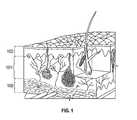
- FIG. 1shows a cross-sectional view of the skin, its internal structures and surrounding tissue.
- FIG. 2shows a cross-sectional view of a target tissue having a zone of thermal treatment according to one embodiment.
- FIG. 3shows a device having an energy applicator according to one embodiment.
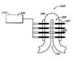
- FIG. 4shows an isometric view of a non-invasive energy delivery device comprising multiple microwave antennas electrically connected to a microwave generator according to one embodiment.
- FIG. 5shows a cross-sectional side view of the non-invasive energy delivery device of FIG. 4 delivering energy into the skin.
- FIG. 6Ashows a monopole antenna according to one embodiment.
- FIG. 6Bshows a dipole antenna according to one embodiment.
- FIG. 6Cshows a helical antenna according to one embodiment.
- FIG. 6Dshows a loop antenna according to one embodiment.
- FIG. 6Eshows a monopole antenna with a conductive shield or sleeve according to one embodiment.
- FIG. 6Fshows an antenna haying a shaped outer conductor according to one embodiment.
- FIG. 6Gshows an antenna having a shaped outer conductor according to a second embodiment.
- FIG. 7Ashows a cross-sectional view of an antenna having an inner conductor disposed within a coaxial cable according to one embodiment.
- FIG. 7Bshows a coiled antenna having a coiled conductor element formed entirely from a coaxial cable according to one embodiment.
- FIG. 7Cshows a coiled antenna having a coiled conductor element formed from an inner conductor according to one embodiment.
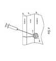
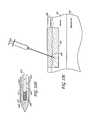
- FIG. 8shows a needle injecting fluid near the base of a sweat gland and target tissue according to one embodiment.
- FIG. 9shows a number of possible configurations of bipolar electrodes with respect to a desired treatment zone.
- FIG. 10shows an RF delivery device having one or more energy delivery elements comprising electrode-tip needles, microneedles or stylets for insertion into the skin according to one embodiment.
- FIG. 11shows an energy delivery device comprising a needle configured for percutaneous insertion according to one embodiment.
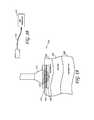
- FIG. 12Ashows a cryogenic system configured to have an interstitial element comprising at least two concentric tubes according to one embodiment.
- FIG. 12Bshows a cryogenic system configured to have an interstitial element configured with a tubular coil residing inside the element.
- FIG. 12Cshows a cryogenic system configured to have an interstitial element configured with a tubular coil residing partially inside and partially outside the element.
- FIG. 12Dshows a cryogenic system configured to have an inner portion and outer portion such that nitrous oxide gas exits the distal portion of the inner tube and absorbs thermal energy from the distal portion of the outer tube.
- FIG. 12Eshows the injection of a cryoprotective agent according to one embodiment.
- FIG. 12Fshows a zone of protected non-target tissue between a cold source at the skin surface and the cryogenic treated region of target tissue according to one embodiment.
- FIG. 13shows a layer of colored bioresorbable microspheres deposited into or around target tissue according to one embodiment.
- FIG. 14shows a carrier solution being introduced by a hollow needle into a planar interface between the dermal layer and subcutaneous layer according to one embodiment.
- FIGS. 15 and 15Ashow needles comprised of at least one chromophore on their tips according to one embodiment.
- FIG. 16shows a microneedle configuration having a non-detachable chromophore tip according to one embodiment.
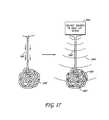
- FIG. 17shows topically-applied aluminum ion particles migrating down a sweat gland duct.
- FIG. 18Ashows a microneedle patch according to one embodiment.
- FIG. 18Bshows an ultrasonic transducer emitting waves as part of an ultrasound treatment according to one embodiment.
- FIG. 18Cshows a planar ultrasonic transducer emitting waves as part of an ultrasound treatment according to one embodiment.
- FIG. 19shows the thermal disablement of sweat glands using a controlled chemical reaction according to one embodiment.
- FIG. 20Ashows a sweat duct
- FIG. 20Bshows the sweat duct of FIG. 20A having a layer of insulation according to one embodiment.
- FIG. 20Cshows a sweat duct of FIG. 20B having a layer of insulation and being treated with electrical energy according to one embodiment.
- FIG. 21Ashows a probe equipped with a retractable blade in a non-retractable position percutaneously inserted under a sweat gland according to one embodiment.
- FIG. 21Bshows the probe of FIG. 21A having the retractable blade in a retracted position according to one embodiment.
- FIG. 21Cshows the probe of FIG. 21B having the retractable blade in an advanced position from its retracted position such that the sweat gland is sheared according to one embodiment.
- FIG. 22Ashows a wire device having an actuator to bow out the wire into an expanded profile according to one embodiment.
- FIG. 22Bshows an actuator having an outer element and inner element according to one embodiment.
- FIG. 23shows a planar cutting device comprising a pinwheel cutter according to one embodiment.
- FIG. 24shows a wire tunneled through target tissue through two insertion points in the skin according to one embodiment.
- FIG. 25shows a wire configured to be inserted into target tissue and exiting the target tissue through a sole insertion point according to one embodiment.
- FIG. 26Ashows a tunneling instrument having an actuator according to one embodiment.
- FIG. 26Bshows a tunneling instrument having an actuator according to another embodiment.
- FIG. 27shows sweat gland ducts filled with photodynamic glue according to one embodiment.
- FIG. 28shows biocompatible scaffolding introduced into a sweat duct according to one embodiment.
- FIG. 29shows a piston used to deliver pressurized gas to a sweat gland according to one embodiment.
- FIG. 30Ashows a sweat gland having liquid according to one embodiment.
- FIG. 30Bshows the sweat gland of FIG. 30A ruptured after the liquid has frozen.
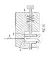
- FIG. 31shows a device for causing pressure-induced necrosis in sweat glands according to one embodiment.
- FIG. 32shows a target tissue having microbubbles and microspheres subject to rupturing by an ultrasonic transducer device according to one embodiment.
- FIG. 33shows a cross-sectional view of a target tissue having a zone of thermal treatment according to one embodiment.
- FIG. 34Ashows an isometric view of a non-invasive energy delivery device comprising multiple microwave antennas electrically connected to a microwave generator according to one embodiment.
- FIG. 34Bshows a schematic view of a cooling source located remotely from an energy source and energy applicator according to one embodiment.
- FIG. 35Ashows a needle configured with a proximal region comprising a cooling element and a distal end comprising an electrode tip according to one embodiment.
- FIG. 35Bshows an energy delivery device element comprising a metal electrode, an inner tube and an outer circumferential surface according to one embodiment.
- FIG. 36shows an energy delivery device comprising a bipolar pair of needle-tipped electrodes according to one embodiment.
- FIG. 37Ashows a cooling electrode comprising a heat sink positioned between two pairs of bipolar needle electrodes according to one embodiment.
- FIG. 37Bshows cooling electrodes in an alternating sequence with monopolar electrodes according to one embodiment.
- FIG. 38shows a side view of a vacuum pulling and holding skin according to one embodiment.
- FIG. 39shows a needle comprising an energy delivery element according to one embodiment.
- FIG. 40shows a side view of a vacuum pulling and holding skin implanted with electrodes according to one embodiment.
- FIG. 41shows an example of a typical skin fold.
- FIG. 42shows a skin fold being treated by an energy delivery device comprising two energy delivery elements according to one embodiment.
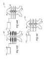
- FIG. 43Ashows a minimally-invasive RF delivery device comprising one or more needles for insertion into a skin fold according to one embodiment.
- FIG. 43Bshows a minimally-invasive microwave delivery device comprising one or more microwave antennas for insertion into a skin fold according to one embodiment.
- FIG. 43Cshows a minimally-invasive cryogenic therapy device comprising one or more injection needles, catheters, stylets, cannulas or catheters according to one embodiment.
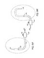
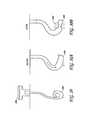
- FIG. 44shows an energy delivery device according to one embodiment inserted through an edge of a skin fold and positioned along the longitudinal axis of the fold.
- FIG. 45shows an energy delivery device according to one embodiment inserted at the top of a skin fold.
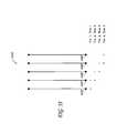
- FIG. 46Ashows an array of monopolar electrode needles used to deliver treatment along the longitudinal length of a skin fold according to one embodiment.
- FIG. 46Bshows an array of monopolar electrode needles used to deliver treatment along the longitudinal length of a skin fold according to another embodiment.
- FIG. 47Ashows an energy delivery device inserted at the top of a skin fold after a needle and blunt dissector electrode are inserted according to one embodiment.
- FIG. 47Bshows an energy delivery device inserted at the top of a skin fold after a needle and blunt dissector electrode are inserted according to an alternate embodiment.
- FIG. 48shows one or more paddle elements connected to a vibration source removably coupled to each outer side of a skin fold according to one embodiment.
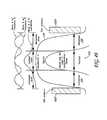
- FIG. 49shows a skin fold being treated by two ultrasonic transducers positioned on two sides of the skin fold according to one embodiment.
- FIG. 50Ashows an ultrasonic delivery instrument used to deliver ultrasound treatment on one side of a skin fold according to one embodiment.
- FIG. 50Bshows light energy being radiated to the skin fold from one energy source according to one embodiment.
- FIG. 51shows a perspective view of a suction electrode comprising a housing, a tissue chamber, a vacuum port and electrodes according to one embodiment.
- FIG. 52Ashows a perspective view of a clamp used to create and hold a skin fold according to one embodiment.
- FIG. 52Bshows a side view of a clamp used to create and hold a skin fold according to a second embodiment.
- FIG. 52Cshows a side view of the clamp of used to create and hold a skin fold according to a third embodiment.
- FIG. 53shows an array of electrodes configured to deliver energy according to one embodiment.
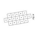
- FIG. 54shows one embodiment of a representative grid indicating target treatment sites “A” and target treatment sites “B” that could be used over a skin area to identify specific areas of treatment.
- FIG. 55A-Eshow a variety of patterns illustrating specific areas of treatment and non-treatment sites that could be used over an area of skin.
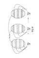
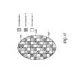
- FIG. 56shows three templates to be used in a staged treatment, wherein each template is configured to allow treatment to a different portion of the overall treatment area according to one embodiment.
- FIG. 57shows a single template pattern represented by different chromophores corresponding to different stages of treatment according to one embodiment.
- Sweatingis both a normal thermoregulation process for human beings and a normal physiological response to a psychological stress or emotional stimuli. For most people, sweating is only a minor cosmetic annoyance. For others, however, sweating may be excessive and abnormal and, consequently, become a socially embarrassing condition.
- Some embodiments of the present inventionrelate to methods for reducing sweat production via the removal, disablement, incapacitation or destruction of sweat glands in the subcutaneous tissue of a human being.
- Hyperhidrosisis a clinically diagnosed disorder in which there is excessive secretion of sweat from the sweat glands.
- the excessive sweatingwhich is thought to result from the over activity of the sympathetic nervous system, usually occurs in the palms, soles, and axillae.
- Palmar hyperhidrosisis a condition of excessive sweating in the hand. This condition is often exhibited in cold, wet handshakes.
- Plantar hyperhidrosisis a condition of excessive sweating in the foot. This condition may cause blisters and fungal infections.
- Axillary hyperhidrosisis a condition of excessive sweating in the armpit. Such excessive sweating is not only socially embarrassing, but may even cause staining and rotting of clothes.
- the sweat glands in the bodyare comprised of the apocrine and eccrine glands.
- Eccrine sweat glandswhich lie superficially in the dermis layer of the skin, are located all over the body so that they can secrete sweat to regulate body heat and temperature.
- Apocrine glandswhich exist within the subcutaneous tissue and border on the interface between the subcutaneous tissue layer and dermal layer, secrete an oily, milky, protein-rich product into the follicles. Bacterial digestion of apocrine sweat is largely responsible for osmidrosis or bromohidrosis (i.e., body odor), which can be most pronounced in the foot and underarm area.
- Antiperspirantsare aluminum based salts that mechanically block the sweat gland ducts, thereby preventing sweat from reaching the skin surface.
- Deodorantschange the pH of the skin surface, thereby minimizing the presence of smell inducing bacteria. Because the effects of both of these products are temporary and can irritate the skin in some users, these products are suboptimal solutions to cases of excessive sweating.
- Anticholinergic drugshave also been applied both topically and systemically to treat hyperhidrosis. These agents block the sympathetic stimulation of the eccrine glands by inhibiting the action of acetylcholine at the nerve synapse. Use of these drugs is limited because of the systemic side effects they can cause, including, dry mouth, urinary retention, constipation, and visual disturbances such as mydriasis and cycloplegia. Moreover, topical anticholinergics sometimes have difficulty absorbing into the skin in sufficient quantities to affect the cholinergic nerve endings.
- botulinum type-A neurotoxine.g., BOTOXTM
- BOTOXis commonly used by dermatologists to denervate the neuroglandular junctions between the autonomic nerves and the sweat glands. With the nerve connections disabled, acetylcholine is prevented from reaching the eccrine sweat glands, thereby disabling a component of the hyperhidrosis patient's overactive sympathetic nervous system.
- This treatmentis not without its downsides.
- Botulinum toxinis one of the most lethal substances on earth and, consequently, injecting it in a patient's body is full of risk.
- botulinum toxin treatmentalso requires multiple, painful injections with a needle. Furthermore, the results of this treatment last only a few months, thereby necessitating repeated costly and painful treatments.
- FIG. 1is an isometric view of a cross-section of the skin, its internal structures and surrounding tissue.
- the skincomprises three principal layers, the epidermis 102 , dermis 101 and subcutaneous tissue 100 .
- the epidermis 102is the thin, epithelial surface of the skin.
- the epidermis 102is comprised of several sub-layers, including, the stratus corneum, keratinocytes layer and basal layer.
- the epidermis 102also contains melanin producing melanocyte cells, which are responsible for skin pigmentation.
- the thickness of the epidermis 102ranges from 0.05 mm to 1.5 mm depending on the location of the skin on the body.
- the dermis 101is the middle layer of the skin and is composed of blood vessels, lymph vessels, hair follicles, sebaceous glands, eccrine glands and, occasionally, apocrine glands.
- the dermis 101is held together by fibroblast cells that may be present as collagen protein, elastic tissue and/or reticular fibers.
- the dermis 101 layeralso contains neural receptors corresponding to the pain and touch senses.
- the dermis 101varies in thickness depending on the location of the skin. The thickness of the dermis 101 can range from 0.3 mm at the eyelid to 3.0 mm on the back.
- the subcutaneous tissue 100is a layer of fat and connective tissue that houses larger blood vessels and nerves. While apocrine glands will sometimes be located in the dermis layer of the skin, it is more common for these glands to reside in the subcutaneous tissue. This layer 100 provides a thermal barrier to help conserve body heat and additional cushion to protect the organs from injury due to trauma. Beneath the subcutaneous layer lies the muscular frame of the body.
- Eccrine glandsare distributed over the entire body surface with a density ranging from 50 glands per square centimeter to 200 glands per square centimeter. These glands are most densely located on the palms of hands, soles of feet, forehead and underarms.
- An eccrine glandcomprises three distinct portions: (1) the intraepidermal portion, (2) the intradermal duct (coiled and straight duct), and (3) the secretory portion (coiled gland).
- the coiled glandis located in the deep dermis or at the border of the dermis 101 and subcutaneous layer 100 .
- the intradermal ductextends upward from the coiled gland through the dermis 101 , first as the coiled duct, and then as the straight duct.
- the straight ductends as it enters into the epidermis 102 and then spirals as it continues through the epidermis 102 and opens directly onto the skin surface.
- Human eccrine sweatis composed of water, sodium, potassium lactate, urea, ammonia, serine, ornithine, citrulline, aspartic acid, heavy metals, organic compounds, and proteolytic enzymes. Generally, the concentration of sodium in eccrine sweat varies from 35-65 mmol/l.
- the eccrine glandsare controlled by sympathetic cholinergic nerves which are controlled by the hypothalamus.
- the hypothalamussenses core temperature directly and also obtains input from temperature receptors in the skin.
- Production of eccrine sweatis initiated by the hypothalamus through postganglionic fiber production of acetylcholine.
- Apocrine glandsare primarily present in the armpits and around the anogenital areas. These glands are comprised of: (1) a coiled gland in the deeper parts of the dermis or at the junction of the dermis and subcutaneous fat; and (2) a straight duct which traverses the dermis and empties into the isthmus (uppermost portion) of a hair follicle.
- the lumen of the coiled portion of the apocrine glandis approximately ten times the diameter of its eccrine counterpart.
- the straight ductruns from the coiled gland to the isthmus of the hair follicle and is virtually identical in appearance to the eccrine straight duct.
- Emotional stressorsstimulate the sympathetic adrenergic nerves, which initiate the release of viscous, fatty sweat from the apocrine glands.
- the amount of sweat produced by these glandsis significantly smaller than that produced by the eccrine glands.
- apocrine sweatdevelops an odor when it comes into contact with the surface of the skin, wherein surface bacteria breaks down the organic compounds in the sweat and produces an odor.
- apoeccrine glandsAnother type of sweat producing glands, the apoeccrine glands, are sometimes found in the axillae (underarms). These hybrid sweat glands are most commonly found in hyperhidrosis patients and are thought to play a role in axillary hyperhidrosis. Their secretory portion has both a small diameter portion similar to an eccrine gland, and a large diameter portion which resembles an apocrine gland. These glands are similar to eccrine glands in that they respond mainly to cholinergic stimuli, and their ducts are long and open directly onto the skin surface. However, apoeccrine glands secrete nearly ten times as much sweat as eccrine glands.
- tissue structures and medical conditionsthat may be treated using systems, methods, devices of some embodiments disclosed herein are described, for example, at pp. 1-10 of U.S. Provisional App. No. 61/013,274 which is incorporated by reference in its entirety.
- Embodiments of the present applicationrelate to methods and apparatuses for reducing sweat production via the removal, disablement, incapacitation or destruction of apocrine and eccrine glands in the dermal and subcutaneous tissue. It is envisioned that many mechanisms and modalities can be implemented individually or in combination to achieve a reduction in sweat production in a patient. It is contemplated that the treatments disclosed herein could be applied to any part of the body that is responsible for or contributes to the production, secretion and/or presence of sweat.
- a target area on a target patientis first identified. More preferably, particular sweat glands or an area containing such sweat glands may be identified, and the sweat glands and/or surrounding tissue can be treated with energy.
- This energycan take many forms (e.g., electromagnetic, microwave, radiofrequency, laser, infrared, ultrasound, etc.) and can be delivered any number of ways (e.g., topically, minimally-invasively, etc.).
- the devices employed in an energy treatmentmay include one or more electrodes, antennas, transducers, needles, probes, catheters, microneedles and stylets. Some of the other thermal treatments that can be employed include inductive heating, resistive heating, hyperthermic chemical reactions and/or cryogenic therapy.
- thermal protective treatmentscan be employed to prevent damage or pain to non-target tissue.
- thermal protective treatmentsmay be used.
- surface coolingcan be applied to protect the epidermal layer and portions of the dermal layer of the skin while deeper regions of skin tissue are heated via energy delivery.
- active and passive cooling or heatingcan be configured to provide this thermal protection to non-target tissue.
- the sweat glandscan be surgically excised, sheared using various wires and/or blades, sealed and plugged shut, ruptured under pressure and disabled via acoustic cavitation.
- a reduction in sweat productionmay be facilitated by administering many of the treatments disclosed herein in one or more spatial configurations or skin geometries.
- treatmentcan be directed perpendicular to the skin surface, parallel to the skin plane or at some angle in between.
- treatmentcan be administered to skin in a flat, planar configuration, in an elevated orientation or in a folded geometry.
- a reduction in sweat productionmay also be facilitated by administering treatment over multiple stages and in a patterned arrangement. This approach can enhance the body's healing response, making for a quicker recovery with fewer complications.
- Various templatesare disclosed to assist in administering a staged and patterned treatment.
- FIG. 2shows a cross-sectional view of the skin, its three primary layers and internal structures.
- the target tissue 105 regionmay begin anywhere from about 0.5 mm to about 4 mm beneath the skin's surface and end anywhere from about 1 mm to about 10 mm beneath the skin's surface.
- the superficial non-target tissue 103 regionmay begin at the skin surface and end anywhere from about 0.5 mm to about 4 mm beneath the skin's surface.
- the deep non-target tissue region 104may begin anywhere from about 1 mm to about 10 mm beneath the skin's surface.
- the target tissue regionmay begin anywhere from about 1 mm to about 3 mm beneath the skin's surface and end anywhere from about 3 mm to about 8 mm beneath the skin's surface. Therefore, a treatment that concentrates energy from about 1 mm to 8 mm beneath the skin's surface in the axillae would be beneficial in treating axillary sweating.
- eccrine glands, apoeccrine glands, and apocrine glandsmay be separately or collectively referred to as sweat glands or target structures.
- treatment, treatment effect, treating area/regionmay relate to the treatment of the target tissue and/or any target structures residing therein for the purpose of temporarily or permanently reducing or halting sweating, wherein the treatment itself may impact the target tissue and/or target structures in one or more of the following ways: modification, deactivation, disablement, denervation, damage, electroporation, apoptosis, necrosis, coagulation, ablation and destruction.
- the methods and apparatuses discussed hereinare directed to the reduction of sweat production in sweat glands, the disclosed methods and apparatuses can be modified, and may be used for treating various kinds of target tissue and non-target tissue regions within the skin.
- the treatments disclosed hereincan be used to, in certain embodiments, (1) tighten skin, reduce wrinkles and contour the skin by treating collagen, induce collagen formation and/or shrink collagen, (2) treat acne by targeting sebaceous glands within the dermis layer of the skin, (3) stimulate or retard hair growth, or temporarily or permanently remove hair by treating hair follicles and/or (4) treat cellulite for the purposes of weight loss and/or body sculpting.
- a systemcan be configured to include a processor, an energy generator connected to the processor, and a device operatively coupled to the generator.
- the devicecan further include an energy delivery applicator or energy delivery element for delivering energy to the target tissue.
- a cableelectrically connects the device to an energy generator.
- the processor, the device, and/or the energy generatorcan be connected wirelessly via, for example, radio frequency signals.
- electrodeindividually and collectively encompass, but are not limited to, the use of one or more types of energy transfer modalities, including electromagnetic, x-ray, radiofrequency (RF), DC current, AC current, microwave, ultrasound (including high intensity focused ultrasound (HIFU)), radiation, near infrared, infrared, light/laser, cooling and cryotherapy, adapted and applied in ranges, intensities and/or quantities sufficient to treat, directly or indirectly (e.g., heating an intermediary substance) the target skin tissue via thermally or by other means.
- RFradiofrequency
- DC currentincluding high intensity focused ultrasound (HIFU)
- HIFUhigh intensity focused ultrasound
- radiationnear infrared, infrared, light/laser, cooling and cryotherapy, adapted and applied in ranges, intensities and/or quantities sufficient to treat, directly or indirectly (e.g., heating an intermediary substance) the target skin tissue via thermally or by other means.
- HIFUhigh intensity focused ultrasound
- the embodimentcan be adapted to accommodate other forms of energy transfer. Even if a mechanism of energy transfer differs significantly from that disclosed in an illustrated embodiment, it should be understood that such mechanism can be employed by this embodiment.
- the energy generatorin one embodiment can generate an electric signal having a desired frequency, amplitude, and power level, and the cable can transmit the generated signal to the device, which comprises an electrode.
- the processoris in communication with the energy generator to control the power output of the energy generator for providing the desired amount of energy to heat the target tissue.
- the energy generatorcan supply the device with voltage to thermoelectrically cool the target tissue.
- a temperature of at least about 50 degrees C. in the target tissue and/or target structures thereinit would be desirable to reach a temperature of at least about 50 degrees C. in the target tissue and/or target structures therein to achieve a treatment effect. For example, it is believed that delivering thermal energy sufficient to heat the target tissue to about 60 degrees C. would likely result in thermal ablation of the target tissue. In embodiments relating to cooling the target tissue, it is believed that cooling the target tissue from about 0 degrees C. to ⁇ 40 degrees C. would likely result in a treatment effect to the target tissue.
- the system illustrated in FIG. 3shows a device 110 having an energy applicator 111 for non-invasively delivering microwave energy 112 to the target tissue layer 105 and a microwave generator 113 for supplying the applicator 111 with microwave energy 112 .
- the energy applicator 111comprises one or more antennas for delivering microwave energy 112 to the target tissue 105 .
- the antennaswould be configured, when the device 110 is placed against or near the patient's skin, to heat and treat the target tissue 105 and target structures within the target tissue 105 .
- the treated tissuecould either be left in place to be resorbed by the body's immune system and wound healing response, or could be extracted using any number of minimally invasive techniques.
- the antennamay also comprise a horn shape, as described below, to provide a directional component to the energy field.
- the energy generator 113is remotely located from the energy applicator 111 , wherein the generator 113 can be either stationary or mobile.
- the applicator 111 and generator 113can be coupled such that they comprise a portable unit.
- the applicator 111 and generator 113can be combined into a single unit.
- Microwave energyis absorbed by the tissue in a process called dielectric heating.
- Molecules in the tissuesuch as water molecules, are electric dipoles, wherein they have a positive charge at one end and a negative charge at the other.
- the microwave energyinduces an alternating electric field
- the dipolesrotate in an attempt to align themselves with the field. This molecular rotation generates heat as the molecules hit one another and cause additional motion.
- the heatingis particularly efficient with liquid water molecules, which have a relatively high dipole moment.
- the delivery of energy to the target tissuecan be facilitated by antenna designs that incorporate a dielectric element.
- a dielectric elementUnlike other forms of electrical energy delivery, such as radiofrequency, where energy is typically transmitted through direct electrical contact between a metal conductor and body tissue, microwave energy can be delivered across a dielectric material.
- a dielectric elementwill not block the microwave energy from radiating to adjacent tissue, but it may help optimize the delivery of energy to the target tissue over the course of the treatment. Since the dielectric heating properties and thermal conductivity of skin tissue change over the course of the treatment (e.g., as temperature rises) due to loss of moisture, a dielectric that is properly matched to the antenna design can maintain the delivery of energy to the target tissue.
- the antenna designcould be optimized by incorporating a covering comprising a dielectric (e.g., ceramic, PTFE, polyimid, etc.) with a dielectric constant that's matched to the heating requirements of the treatment.
- the dielectricmay be incorporated into the antenna or be a separate component of the energy delivery device or system. Further details regarding antenna designs are discussed below.
- FIG. 4is an isometric view depicting a non-invasive energy delivery device 117 comprising multiple microwave antennas 120 electrically connected to a microwave generator 113 .
- the antennas 120are contained in a substantially planar applicator plate 121 sized for application against a target area of a patient's skin 119 .
- the device 117 , and the applicator plate 121 therein,can be sized and configured to substantially match the area of tissue being treated.
- the device 117can be configured to cover substantially all of the axillae region of the patient.
- the device 117can be configured to cover at least a portion of the axilla.
- the applicator plate 121may be flexible to help the device 117 conform to the contours of the patient's skin 119 .
- FIG. 5is a cross-sectional side view of the same device of FIG. 4 showing the delivery of energy 112 into the skin.
- four or five microwave antennas 120are positioned parallel to each other.
- fewer or greater microwave antennas 120may be provided, for example, one, two, three, five, six, seven, eight, nine, ten or more. With this planar configuration, energy can be delivered to a larger area of tissue in one treatment and in a more consistent fashion.
- the applicator plate 121 containing the antennas 120may be connected by a conduit 114 to the microwave generator 113 , with cooling fluid passing through the conduit 114 to and from the applicator plate 121 from a coolant circulator 118 .
- the cooling fluidcreates a protected zone in the epidermis 103 of the patient, so that that target tissue 105 below the protected zone is treated.
- the amount of energy 112 delivered to the target tissue 105 and consequent extent of treatment effectcan be adjusted based on the number of antennas 120 , their specific configuration and the power delivered to each antenna.
- a microwave generator 113 with a microwave energy 112 output frequency ranging from 300 MHz to 20 GHzis suitable for feeding the energy delivery device 117 with power.
- a microwave signal of anywhere from about 915 MHz to about 2450 MHzwould be preferential for yielding a treatment effect on tissue.
- a signal having a frequency ranging from about 2.5 GHz to about 10 GHzmay also be preferential.
- solid state, traveling wave tube and/or magnetron componentscan optionally be used to facilitate the delivery of microwave energy 112 .
- FIGS. 6A to 6Gillustrate several possible variations that can be implemented to achieve the energy delivery function disclosed herein.
- the antennacomprises the distal end of a coaxial cable feedline through which electrical energy is transferred from an energy generator.
- the coaxial cablefurther comprises an inner conductor shaft 124 and outer conductor 125 .
- FIG. 6Ashows one embodiment of a monopole antenna 122 .
- the antennamay be shielded or choked by a metal 127 to limit the electromagnetic field propagated by the antenna.
- an inner conductor element 123extends from the inner conductor shaft 124 and beyond the outer conductor 125 such that the electromagnetic field propagated by the antenna originates from only the inner conductor element 123 .
- dipole antenna 128 configurationsas illustrated in FIG. 6B , the outer conductor 125 is exposed in such a manner that an electromagnetic-field is created between the inner conductor element 123 and outer conductor 125 .
- the antennamay optionally comprise a helical antenna 129 ( FIG. 6C ), loop antenna 130 ( FIG. 6D ) or horn antenna 131 ( FIGS. 6F and 6G ).
- the outer conductor 125may comprise a shaped element, such as a horn shape, to provide a directional component to the field created between the inner conductor element 123 and outer conductor 125 .
- the outer conductor element 125 and/or inner conductor element 123may be bordered by, coupled to or coated by a dielectric element to optimize the energy delivery capabilities of the antenna.
- the energy applicatorcomprises an antenna connected to a coaxial cable that is coupled to a microwave power source.
- the antenna 132further comprises an inner conductor disposed within the coaxial cable 133 , wherein an inner conductor element 123 extends beyond the distal end of the coaxial cable 133 to form a coiled conductor element.
- the coiled conductor elementprovides a relatively flat structure which can be aligned with the skin surface to deliver an even amount of energy to a plane of target tissue.
- the applicatormay optionally further comprise at its distal end a thin shield comprised of a polymer or ceramic.
- FIGS. 7B and 7Cillustrate additional embodiments of the coiled antenna configuration, wherein the coiled conductor element may comprise either the coaxial cable 133 or just the inner conductor 123 .
- FIG. 7Ashows the use of cooling fluid flowing through a coaxial antenna system 132 .
- This antenna embodiment, or any other antenna configuration previously shown, for example FIG. 6Ecan be configured to not only cool the skin, but also to create an area of lower pressure inside the device chamber than in the ambient surroundings. This area of lower pressure or suction within the device will help (1) adhere the device to the skin, bringing the target tissue into closer apposition to the antenna, and (2) reduce blood flow in the target tissue, thereby enabling more efficient heating of the tissue.
- suctionmay help to control pain by triggering stretch and pressure receptors in the skin, thereby blocking pain signals via the gate control theory of pain management.
- the gate control theoryholds that an overabundance of nerve signals arriving at the dorsal root ganglion of the spinal cord will overwhelm the system, and mask or block the transmission of pain receptor signals to the brain. This mechanism of pain management is exploited by implantable electrical pain controls units, TENS systems, the Optilase system and others.
- microwave heatingis particularly efficient when water molecules are present in tissue, it may be desirable to have relatively high water content or molecule density at the target tissue or within the target structures. This high water content would result in greater microwave energy absorption and consequent heating at the point of treatment. Moreover, this phenomenon will allow the selective heating of target tissue, thereby minimizing the impact to non-target tissue.
- FIG. 8shows one embodiment of the injection of fluid 116 to near the base of a sweat gland and target tissue 105 .
- the patientcan be induced to sweat in the area of treatment (such as by raising the ambient temperature or the temperature in the target area) in order to achieve higher water content in the target structures.
- the water dense sweat glandscan be plugged to prevent any of the water/sweat from escaping through the sweat ducts. Sealing the gland ducts can be achieved by using aluminum ion based topical products such as antiperspirants or any type of biocompatible polymer coating.
- embodiments and components of embodiments described herein as well as, for example, those discussed in the previous sentencecan be used to generate tissue profiles as illustrated in FIGS. 26-51 and described in pp. 18-39 of U.S. Provisional App. No. 61/045,937, previously incorporated by reference in its entirety.
- Radiofrequency (RF) energyis another mode of electromagnetic energy delivery that can be used to treat the target tissue.
- a devicecomprising at least one electrode for delivering an electric field therapy is operatively connected to an RF generator for delivering RF energy via the electrode to target tissue.
- the energy deliverymight be continuous or pulsed, thermal or non-thermal.
- a continuous or pulsed electric field delivered from the electrodecan heat the target tissue to a temperature necessary to achieve a desired treatment effect.
- the delivered energycan heat and/or ablate the nerves, neuromuscular junctions and/or neuroglandular junctions associated with the target structures in order to temporarily or permanently denervate the target structures.
- a pulsed electric fieldcan also induce electroporation in these neural structures or the target structures themselves to achieve a treatment effect.
- the electrode(s)can be individual electrodes that are electrically independent of each other, a segmented electrode with commonly connected contacts, or a continuous electrode.
- a segmented electrodecan, for example, be formed by providing an insulated tube with slots into which the electrode is placed, or by electrically connecting a series of individual electrodes.
- Individual electrodes or groups of electrodescan be configured to provide a bipolar signal.
- the electrodescan be dynamically assignable or hardwired to facilitate monopolar and/or bipolar energy delivery between any of the electrodes and/or between any of the electrodes and one or more external ground pads.
- an array of electrodescan be configured such that both a monopolar energy field and a bipolar energy field can be selectively, sequentially, and/or simultaneously delivered.
- a ground padcan, for example, be attached externally to the patient's skin (e.g., to the patient's leg).
- the active electrodesin either monopolar or bipolar configurations. They may be flat or curved to promote uniform contact over the electrode surface.
- the contact area of the active electrodesmay be round (e.g., circular, elliptical) or rectilinear (e.g., square, rectangular, polygonal)—virtually any shape is possible.
- the shapemay be chosen, for example, to suit the tissue to be treated or to allow optimal coverage for repeated activations.
- an electrode with a hexagonally shaped contact areamay offer the advantage of providing complete coverage when treating irregular areas through multiple activations. It will be appreciated that similar shapes may be used for the applicator plate in the microwave embodiments discussed above.
- FIGS. 9A-Fshow a number of possible configurations of bipolar electrodes 201 with respect to a desired treatment zone 105 , including top and side views of alternating configuration electrodes shown in FIG. 9A , top and isometric views of alternating plane configuration electrodes shown in FIG. 9B , trident configuration electrodes shown in FIG. 9C , sandwich configuration electrodes shown in FIG. 9D , flat plate configuration electrodes shown in FIG. 9E , and roof with plate configuration electrodes shown in FIG. 9F .
- the depth of energy penetration, achieved tissue temperature and consequent extent of tissue effect caused by the RF delivery devicewill depend on a number of factors, including, the power delivered by the RF generator, the spacing of the one or more electrodes, the size of the electrodes, the orientation of the electrodes, the amount of contact the electrodes have with the target tissue and the properties of the tissue itself.
- the electrical generatormay be a conventional power supply that operates at a frequency in one embodiment in the range from about 200 KHz to about 1.25 MHz, more preferably about 400 KHz to about 1.0 MHz, with a conventional sinusoidal or non-sinusoidal wave form.
- Such power suppliesare available from many commercial suppliers, such as Valleylab, Aspen, and Bovie.
- generator operabilitymay include a power anywhere from about 1 ⁇ 2 W to about 100 W.
- to achieve the desired treatment effectit may be desirable to continuously deliver energy for periods as short as 1 ⁇ 4 second or as long as 300 seconds.
- PEF parametersmay include, but are not limited to, voltage, field strength, pulse width, pulse duration, the shape of the pulse, the number of pulses and/or the interval between pulses (e.g., duty cycle), etc. in any range and combination.
- Suitable pulse widthsinclude, for example, widths of at least 10 seconds and up to about 500 milliseconds.
- Suitable shapes of the pulse waveforminclude, for example, AC waveforms, sinusoidal waves, cosine waves, combinations of sine and cosine waves, DC waveforms, DC-shifted AC waveforms, RF waveforms, square waves, trapezoidal waves, exponentially-decaying waves, and combinations thereof.
- Suitable numbers of pulsesinclude, for example, at least one pulse.
- Suitable pulse intervalsinclude, for example, intervals less than about 10 seconds.
- the RF delivery device 202can take the form of one or more energy delivery elements comprising electrode-tip needles, micro-needles, or stylets for insertion into or across the epidermal layer 102 of the skin.
- the entire energy delivery elementcan comprise an electrode that is optionally insulated at points along the element where energy delivery is undesirable (e.g., non-target tissue). This minimally-invasive insertion approach allows for a more localized treatment of target tissue 105 such that damage to non-target tissue is minimized.
- the operatorcan direct the RF generator 204 to deliver an electric field to the electrode for subsequent delivery to the target tissue 105 .
- the electric field from the electrodewill resistively heat the target tissue 105 .
- the target tissuecan be heated conductively by adjacent tissue that is resistively heated by the electrode's electric field.
- a needle 203configured with an insulated shaft 205 as illustrated in FIG. 10 can prevent the conduction of heat to non-target tissue alongside the needle shaft 205 .
- a proximal portion of the needleis insulated to the depth of the non-target tissue while the electrode 206 at the distal portion of the needle 203 is exposed to treat the target tissue 105 .
- the electrode 206 tipcan be partially insulated in such a fashion as to provide a directional component to the delivery of RF energy. This directional bias may advantageously provide a means for minimizing energy delivery and consequent thermal damage to non-target tissue.
- Protective treatmentsmay be used with certain embodiments (not shown).
- a cooling system, cooling element or cooling componentmay be provided such as described elsewhere in this specification.
- the cooling elementmay be used in combination with an insulating element, while in another embodiment, the cooling element may be used as an alternative to an insulating element.
- a protective treatmentmay include heating a portion of an energy delivery device.
- the needle electrodes 206 of FIG. 10may have a length of about, for example, 1 to 10 mm, and preferably no greater than about 8 mm. Even more preferably, the needle electrodes 206 may have a length of about 2 to 5 mm in some embodiments. It will be appreciated that the length of the needles 203 may be optimized to be inserted to a depth where the target tissue 105 is located.
- the energy delivery devicecomprises a needle 208 configured for percutaneous insertion.
- the needle 208further comprises a distal portion having one or more energy delivery elements 209 for delivering energy 210 to the target tissue 105 .
- this embodimentmay comprise a needle 208 having one or more electrodes for treating the target tissue with RF energy 210 .
- a portion of the needle 208can be insulated to provide a directional component to the energy delivery. This directional component can advantageously allow for a more controlled treatment, wherein less non-target tissue is damaged.
- the needle 208is insulated so that energy is delivered toward the epidermis 102 and away from subcutaneous 100 tissue.
- the electrode 206 provided on the needle 208may have any suitable length to treat a single sweat gland or multiple sweat glands. Alternatively, multiple electrodes 206 can be placed on the needle 208 spaced apart for treating multiple sweat glands.
- the needle 208can optionally be configured to translate angularly or be “fanned” out parallel to the target tissue 105 .
- the energy delivery element 209can be rotably coupled to the needle 208 so that it may translate parallel to the target tissue 105 .
- a cooling sourcemay be provided on the skin to protect the skin surface, epidermis 102 and parts of the dermis 101 .
- Cryotherapymay present an opportunity to provide a treatment effect on target tissue. Since the collagen matrix of the skin is less sensitive to cold, it is possible to cool target structures without damaging non-target skin tissue comprising collagen.
- the embodiments depicted in FIGS. 10 and 11can also be utilized to treat the target tissue via cryotherapy.
- an interstitial elementcomprising one or more needles, stylets, catheters or probes can be configured with one or more passageways to deliver a cryogenic fluid to at least one thermally conductive element adjacent or near the target tissue to provide treatment to the target tissue.
- the systemcan be configured to have an adjacent or remotely located generator for supplying cryogenic fluid (e.g., liquid nitrogen, liquid helium, liquid argon, liquid carbon-dioxide, liquid nitrous oxide, liquid AZ-50, chilled anti-freeze, chilled alcohol, chilled saline, etc.).
- cryogenic fluide.g., liquid nitrogen, liquid helium, liquid argon, liquid carbon-dioxide, liquid nitrous oxide, liquid AZ-50, chilled anti-freeze, chilled alcohol, chilled saline, etc.
- the generatorshould deliver cryogenic fluid to the device sufficient to reduce the temperature of the target tissue to between about 0 to ⁇ 40 degrees Celsius.
- a temperature of between about 0 to ⁇ 10 degrees Celsiusmay be sufficient to induce necrosis in the target tissue although this may be above the freezing point of the target tissue, whereas a temperature less than about ⁇ 10 degrees Celsius may be sufficient to freeze the target tissue.
- the device 211is configured with an interstitial element 212 comprising at least two concentric tubes 213 , 214 .
- cryogenic fluidcan be delivered through the interstitial element 212 and to the thermally conductive element by the inner tube 213 and then circulated out of the interstitial element 212 through the outer tube 214 .
- the outer tube 214itself can be a thermally conductive element.
- the interstitial element 212could be configured with a tubular coil 215 that resides either inside or outside of the element 212 . The cryogenic fluid would be routed through the lumen of the coil 215 to provide a thermal treatment effect to the target tissue.
- the devicemay comprise a cryoballoon catheter, wherein the thermally conductive element comprises a balloon.
- the thermally conductive elementcomprises a balloon.
- a pressurized liquidsuch as nitrous oxide is routed through the interstitial element's passageway.
- the liquidreaches the balloon it undergoes an endothermic phase change such that the liquid absorbs heat from the surrounding area to achieve a treatment effect on the target tissue.
- FIG. 12Dshows an interstitial element 212 comprising an inner tube 216 and outer tube 217 .
- the inner tube 216comprises an inner lumen 218 for liquid nitrous oxide to travel from a proximal portion 219 to a distal portion 220 of the tube.
- the inner tube 216further comprises at least one port or nozzle 221 along the distal portion 220 of the tube for the liquid nitrous oxide to exit the inner tube 216 .
- the liquid nitrous oxideexits the port 221 at, preferably, high velocities, it undergoes an endothermic phase change, wherein the outer tube 217 is cooled by the nitrous oxide gas.
- the gasabsorbs energy from the outer tube 217 , which comprises the thermal conductive element in this embodiment, and the surrounding target tissue, the gas then exits the interstitial element 212 through the annular space between the outer tube 217 and inner tube 216 .
- the approach disclosed in FIG. 12Dallows for a more focused area of cryogenic treatment.
- the nitrous oxide gasexits the distal portion 220 of the inner tube 216 at its coldest temperature and then absorbs thermal energy from the distal portion 1242 of the outer tube 217 . Following heat exchange with the distal portion 1242 of the outer tube 217 , the gas then travels toward and out the proximal end 219 of the interstitial element 212 . Therefore, the distal portion 1242 of interstitial element 212 , the portion which is adjacent to the target tissue, is the coolest.
- this cryogenic systemcan be adjusted to modulate the temperature of the gas and vary the rate and extent of thermal treatment.
- shape, size and number of nozzle/port openingsmay have bearing on the rate of conduction and convection.
- the size of the annular space between the outer and inner tubes of the interstitial elementwill also impact the heat transfer properties of the device.
- the pressure of the nitrous oxide liquidwill also contribute to the heat exchange capabilities of the treatment.
- Cryotherapymay also be administered topically to treat target tissue below the surface of the skin.
- cryoprotective agents 222such as ethylene glycol, glycerol, erythritol or dimethylformamide can be applied topically or via injection to minimize the treatment effect to non-target tissue 103 .
- Cryoprotective agents 222can also be utilized in conjunction with percutaneous therapies utilizing the interstitial elements discussed above.
- the cryoprotective agents 222can be used to create a zone of protected non-target tissue 223 between the cold source 225 at the skin surface 119 and the cryo-treated region 224 of target tissue.
- Another approach for treating target tissuecomprises the use of phototherapy.
- the unique optical characteristics of target structuresare used to determine a spectral signature for each structure.
- Light energycan be delivered to the target tissue at a wavelength that is matched to the spectral signature of a particular structure to selectively heat and treat the structure through light absorption.
- Phototherapycan also be implemented through coloring the target tissue or area surrounding the target tissue and then delivering light energy to heat the coloring.
- a colored substancecan be introduced into the target tissue and a light energy having a waveform that has a specific absorption for this color can be delivered from an internal or external source to treat the target tissue.
- the principal advantage of this approachis that the target tissue can be selectively colored so that the treatment can be localized to the target tissue with minimal impact to non-target tissue.
- Phototherapycan be performed using various types of light energy, including, but not limited to, laser, intense pulsed light (“IPL”), focused IP, infrared and near infrared.
- IPLintense pulsed light
- These various light energiescan be implemented with any number of energy delivery elements, including, but not limited to, a laser, light emitting diode (“LED”) or light bulb.
- energy delivery elementsincluding, but not limited to, a laser, light emitting diode (“LED”) or light bulb.
- LEDlight emitting diode
- one or more filterscan be used in conjunction with any of these energy delivery elements to remove unnecessary wavelengths, including those that would be absorbed by non-target tissue.
- a chromophorei.e., colored molecule
- the chromophorecan be introduced through the gland ducts via topical delivery, injected to the target tissue or ingested by the patient such that the coloring appears in the patient's sweat (i.e., chromohidrosis).
- AMSallyl methyl sulfide
- an external source or energy delivery elemente.g., light emitting diode “LED”
- a light energy sourcesuch as a laser or other light delivery system specifically matched to one or more chromophores to selectively treat the target tissue.
- This light energycan non-invasively travel down the sweat duct or transcend the layers of epidermis and dermis to reach the target tissue.
- an interstitial deviceutilizing fiber optics can deliver the light energy directly to the target tissue.
- a colored bioresorbable elementcan be introduced into or around the target tissue.
- a layer of colored bioresorbable microspheres 226can be deposited into or around the target tissue 105 .
- the microspheres 226can be injected as part of a bio-inert solution, gel or other carrier with a syringe 227 into or around the target tissue 105 .
- the colored microspheres 226can be heated by laser light 228 from a laser 229 matched to their particular color, thereby conductively heating the target tissue 105 to yield a treatment effect.
- microspheres 226can be comprised of materials, such as polytetrafluoroethylene (PTFE), polymethyl methacrylate (PMMA) or calcium hydroxylapatite (CaHA), and colored to match laser wavelengths that would result in the most efficient heating of the microspheres 226 , with the laser 229 having relatively little impact on the tissue in its path.
- PTFEpolytetrafluoroethylene
- PMMApolymethyl methacrylate
- CaHAcalcium hydroxylapatite
- delivering chromophores in the presence of a carrier solutionmay result in a wider and more even distribution of chromophore prior to treatment.
- a wider and more even distribution of chromophoremay result in a wider and more consistent treatment effect.
- chromophoremay be suspended in a carrier solution of buffered or unbuffered saline prior to injection into the target tissue.
- a carrier solution 230is introduced using a hollow needle 231 into the planar interface between the dermal layer 101 and subcutaneous layer 100 to create a pathway for chromophore migration.
- the carrier solution 230may incorporate drugs for enhancing the distribution and/or effects of the chromophore or facilitating recovery following treatment.
- a neurotoxinin another embodiment associated with the phototherapy approach, can be used as a vehicle to carry a colorant to the neuroglandular or neuromuscular junctions of the target tissue and/or target structures.
- Clostridium botulinum neurotoxinssuch as botulinum toxin type-A
- botulinum toxin type-Acan be administered to treat various neuromuscular and neuroglandular conditions by binding to cholinergic neurons at these junctions and blocking the release of acetylcholine in the synaptic vesicles of the neurons.
- the tissue at the junctionis denervated by this blocking, this result is only temporary.
- light energycan be delivered to thermally ablate these junctions and selectively denervate the target tissue/structure to achieve a longer lasting treatment.
- the toxin itselfcan be colored or alternatively, a chromophore chemically bound to the toxin may be used. Additionally, the light energy delivered to the target tissue will be specifically matched to the colorant to maximize the energy absorbed at the junctions.
- the toxinis a two-chain polypeptide with a 100-kDa heavy chain (“heavy chain”) joined by a disulphide bond to a 50-kDa light chain (“light chain”).
- the heavy chainis responsible for targeting and binding to the cholinergic neurons at and around the injection site and helping the light chain cross the neuron cell's membrane.
- the light chainis responsible for carrying the toxicity to the neuron.
- toxinsfor example, butyricum toxins, tetanus toxins, exotoxins, diphtheria toxins, cholera toxins, ricin, or variants thereof may have the same or substantially similar mechanisms.
- microneedle technologycan be employed to facilitate the delivery of chromophores to the target tissue.
- the microneedlescan be hollow to facilitate the delivery of a colored substance (e.g., liquid or solid chromophore, colored microspheres, etc.) to the target tissue.
- the needlesmay be configured to deliver the chromophores only across the stratum corneum from where the chromophores can migrate to the target tissue via reverse iontophoresis.
- reverse iontophoresisis used to drive the chromophores directly across the epidermis and into the deep dermis.
- the needle tips 232are comprised of at least one chromophore 233 and are configured to detach from the needle 234 when inserted into or alongside the target tissue.
- the needle tip 232may be coated with a chromophore 233 or be comprised of a solid chromophore 233 and the needle shaft 235 may be solid or hollow.
- the microneedles 234can optionally be configured to engage a tip deployment mechanism 237 .
- a tip deployment mechanism 237such as a single plunger or array of plungers, can be utilized to facilitate the detachment of the chromophore needle tip 232 .
- hollow-bodied needles 234can be used to allow the deployment mechanism 237 access to the detachable chromophore tip 232 .
- the deployment mechanism 237can be driven through the needle's lumen 238 to disengage the detachable tip 232 .
- the deployment mechanism 237can comprise a hydraulic element, such as pressurized air, to effect the detachment of the needle tip 232 .
- the needle tip 232 and/or needle shaft 235can be configured with a pre-established weakness to facilitate deployment.
- the needle tip 232can be configured with a notch or groove 236 such that it breaks along the notch or groove 236 following insertion into or prior to retraction from the target tissue.
- the needles 234 shown in FIGS. 15 and 15Amay be joined in an array of needles, such as a linear or planar array.
- the needles 234may have a length of about 2 to 8 mm, more preferably about 4 mm, with the length of the detachable tip 232 being matched to the depth of the target tissue.
- the deployment mechanism 237such as a plunger or array of plungers may detach each needle separately, in a preferential sequence, or all at once.
- the microneedle shaftis comprised of a dissolvable material such that the microneedle shaft dissolves following the microneedle insertion into the skin, leaving the chromophore tip in the target tissue.
- a microneedle arraycan be cast and cured with the distal tips comprising chromophores and the proximal shaft comprising a sucrose solution. Once the microneedle is inserted into the skin, the sucrose shaft will be broken down within the interstitial space of the skin tissue such that the chromophore tip is the only portion of the needle that remains in the skin.
- a flexible backing substrateinto the cast microneedle array such that following insertion into the skin; the backing can be peeled off the microneedle leaving a portion of the needle shaft and chromophore tip within the skin.
- the hollow microneedlescan be utilized as a pathway for delivery of light energy to the deposited colored substance from a source outside the body.
- the microneedlesmay comprise fiber optic material to facilitate the delivery of light to the color at the target tissue.
- the laser deliverycan be set at an intensity and duration sufficient to ablate and vaporize part or all of the deposited material.
- the implantmay eventually be absorbed into the surrounding tissue so there is no adverse physiological or aesthetic impact resulting from the presence of the microspheres or color.
- any remaining colorcan be bleached by light at the treatment wavelength, or an alternate wavelength, such that it is no longer visible in the skin.
- the chromophoremay not be bioresorbable, or bleachable, but rather the light energy may fracture the chromophore into particles small enough to be phagocytosed and cleared from the body by the immune system.
- This mechanism of actionis well known in the area of tattoo removal, where, for instance, carbon black tattoo inks are fractured by laser light and cleared by the body.
- the chromophore tipis configured to be removed from the target tissue along with the needle. In this configuration the tip is not detachable from the needle shaft.
- This intact microneedle 239 configurationis illustrated in FIG. 16 .
- the needle 239may comprise a proximal portion 240 made of an optically clear material or an optically neutral chromophore (i.e., unable to absorb, block or otherwise be activated by the treatment wavelength) and a distal portion 241 made of a chromophore.
- the proximal portion 240 of the needle 239can be configured as a light pipe or lens to focus the light energy into the chromophore tip 232 .
- an array of needlesinto an optically neutral backing system.
- This arraycomprising chromophore tips and optically neutral shafts, configured with a geometry and needle density to optimize the treatment to target tissue, can be permanently coupled to an optically neutral backing system to form a microneedle patch.
- light energycan be applied to the optically neutral backing such that this energy is delivered via the optically neutral shafts and absorbed by the chromophore tips of the needles. The absorbed energy will heat the chromophore tip and thereby treat the surrounding target tissue.
- the patchcan be any size, shape and geometry necessary to match the treatment area.
- the patch's backingmay comprise a flexible material to allow the patch to conform to the patient's skin.
- the backing systemmay also comprise an optically neutral adhesive on the portion most proximate to the skin to minimize movement of the patch during treatment. The use of adhesive may provide significant benefit in avoiding targeting error of treatment or patient discomfort from needle motion.
- a druginto the adhesive, backing, or proximal portion of the needle shaft to facilitate healing of non-target tissue.
- the needles or patchcan optionally be left inserted into the patient's skin following treatment of the target tissue to serve as an integral bandage.
- These healing drugsmay comprise steroids, non-steroidal analgesics or anti-inflammatory medications such as antibiotic cream.
- the needlemay be fully or partially coated with a chemical substance, such as a sclerosing agent, to enhance treatment of the target tissue.
- an optically neutral backing, adhesive and/or needlecan be designed such that when a prescribed amount of energy is transmitted through the system, at least a portion of the component becomes optically opaque to the treatment wavelength, thereby preventing additional energy from reaching the chromophore tips and heating the target tissue.
- these componentscan be heat or temperature sensitive such that energy delivery is blocked once the target tissue or non-target tissue reach a prescribed threshold temperature.
- the backing materialmay be configured to be opaque, blocking the light delivery to all but the proximal needle shafts, which extend through the backing material to the upper surface of the array system, thereby blocking light delivery to all tissue except those directly in contact with the chromophore tips.
- any of the phototherapy applicationsit may be desirable to monitor absorption of the light spectra within the tissue in order to detect changes in the absorption spectra. Changes in the absorption characteristics of the tissue are indicative of changes within the tissue, and can be used to detect treatment efficacy, control extent of treatment, or confirm completion of treatment.
- Another method of providing a treatment effect to target tissuecomprises inductively heating particles within or around the target structures.
- These particlesare preferably metallic (e.g., iron) and of a size that can be introduced into the target tissue region in a non-invasive or minimally invasive manner.
- a solution of micro-sized ferromagnetic particlescan be introduced into the target tissue via injection with a syringe.
- an electromagnetic energy sourcefrom either inside or outside the body can generate an electromagnetic field to create a current in the metallic particles in vivo. These currents will cause resistive heating of the particles and the consequent conductive heating of the target tissue.
- the electromagnetic energy sourcecan continue delivery of energy to the particles until treatment of the target tissue is completed.
- the particlesmay be introduced topically via the sweat gland ducts.
- topically-applied particlescan be introduced into the sweat gland ducts.
- these particles 242can migrate naturally down the duct 109 and into the coil of the gland.
- pressurecan be used to facilitate the travel of these particles 242 to the sweat gland.
- iontophoresismay facilitate the delivery of metallic particles 242 into the sweat glands.
- electromagnetic energy 243may be delivered from an electromagnetic energy source 244 to heat the particles 242 and surrounding target tissue 105 until the treatment is completed (e.g., sweat production in the sweat gland has halted and/or the sweat gland has been thermally ablated).
- ferromagnetic particlescan be substituted for chromophores
- ferromagnetic fluidic suspensionscan be used instead of colored solutions
- ferrous-tipped microneedlescan be used in place of chromophore-tipped microneedles.
- a microneedle patchcomprising a non-magnetic backing system, non-magnetic needle shafts (or proximal portions of the shafts) and non-detachable ferro-tipped microneedles may be employed.
- this embodimentcan incorporate an electromagnetic element 245 directly into the backing material 1249 .
- This electromagnetic element 245can be any structure or material, such as a metal wire, that has electromagnetic properties and is electrically connected to an energy source.
- the electromagnetic element or an electromagnetic sourcedelivers a field 246 to resistively heat the tips 247 , thereby treating the target tissue 105 .
- the microneedle patch 248is removed from the patient along with the non-detachable ferromagnetic tips 247 .
- Ultrasonic energycan be used as another means of treating the target tissue.
- ultrasound hyperthermiacan be induced by delivering an ultrasonic wave to target tissue, causing the tissue to vibrate and heat.
- Wave frequencies between about 20 kHz and 18 MHz with powers ranging from about 0 to 50 W/cm 2can achieve these results.
- Treatmentmay be more effective at frequencies between about 0.1 MHz and 3 MHz and powers from about 720 mW/cm 2 to 50 W/cm 2 .
- one or more ultrasonic transducersemit waves which meet at a specific focal point at a prescribed distance from the transducer. As shown in FIG. 18B , the convergence of these waves 249 from an ultrasonic transducer 251 causes an intense, cumulative effect at the focal point 250 . Once each wave 249 passes the focal point 250 , it continues along its radial path and disburses.
- Multiple transducer embodimentsmay be oriented in any number of configurations, including linear, radial, and semi-spherical arrays.
- the emitted wavesdo not converge at a specific point. As shown in FIG. 18C , the waves 249 instead travel in a planar fashion from the edge of the transducer 252 . Additionally, the ultrasound signal can be attenuated such that it terminates at a given distance and does not propagate into the deep non-target tissue. Both planar 252 and focused 251 transducers may induce ultrasound hyperthermia. Used in conjunction with technology for protecting non-target tissue (e.g., cooling system/element), as described elsewhere herein, both methods of ultrasound can isolate heating to the target tissue.
- non-target tissuee.g., cooling system/element
- the sweat glandsare thermally disabled by a controlled chemical reaction.
- This chemical reactioncan be either exothermic or endothermic and can involve one or more components.
- the componentscan reside in one or more chemical reservoirs 253 in communication with an interstitial probe 254 .
- the probe 254comprises at least one lumen 255 in communication with the chemical reservoir(s) 253 , a sharp tip 256 for penetrating the skin and entering the target tissue and a thermally conductive element 257 comprising a thermally conductive material (e.g., a metal such as copper).
- the thermally conductive element portion 257 of the probe 254is configured to be positioned adjacent the target tissue.
- the probe 254 with the sharp tip 256approaches the target tissue parallel to the skin, with a portion of the skin 177 lifted to allow the tip 256 to puncture through tissue.
- the thermally conductive material 257is positioned at a location on the probe 254 to be located in the target tissue region. Further details regarding this delivery mechanism are described below.
- the componentscan be delivered simultaneously or sequentially such that they mix and undergo a reaction in the thermally conductive element 257 .
- acide.g., HCl, H 2 SO 4
- waterfor example, can be delivered into the thermally conductive element 257 in sufficient amounts to generate sufficient heat to disable and/or ablate the sweat glands via conduction across the element 257 .
- supersaturated sodium acetateis introduced into the thermally conductive element 257 wherein heat is generated as the solution crystallizes.
- the componentscan be mixed prior to introduction into the thermally conductive element 257 .
- a catalystcan be placed within the thermally conductive element 257 , or elsewhere along the probe's lumen 255 , to facilitate the chemical reaction.
- a solutioncan be used to carry an electric charge to treat the target tissue.
- an electrically conductive liquidsuch as a hypertonic solution (e.g., saline)
- a hypertonic solutione.g., saline
- the needleitself may comprise an electrode to directly charge the solution once it is deposited in or adjacent to the target tissue.
- an array of microneedles(such as that shown in FIG. 14 ) but also comprising electrodes can be used to deliver hypertonic solution to the target tissue, wherein the tissue is treated by the electrical charge conducted through the solution following activation of the electrodes.
- FIGS. 20A-20Cillustrate a method of delivering an electrical charge to sweat glands via the sweat.
- an insulator coating 258to cover the skin surface and duct 109 walls while still leaving a path for the sweat to travel from the sweat gland to the surface.
- the patientcan be induced to sweat by administering an injection of epinephirine or a cholinergic agent or agonist, stimulating the nerves with an electrical signal, and/or increasing the patient's body temperature via exercise or other means.
- an energy sourcee.g., RF generator 204
- the operatorcan apply electrical energy 259 from an energy source (e.g., RF generator 204 ) to this surface sweat.
- the electrical energy 259 from the energy source 204can reach and disable the sweat gland. It may be desirable for the operator to induce sweating for the entirety of the treatment to maintain continuity of the conductive path in some embodiments.
- a chemical treatment substancecan be introduced into or near the target tissue to cause a chemical reaction and resulting treatment effect.
- a chemical treatment substancecan be introduced into or near the target tissue to cause a chemical reaction and resulting treatment effect.
- alcohols, acids or basescan be delivered to the target tissue to chemically ablate the tissue.
- the injection of small quantities of acidssuch as tricholoracetate or alphahydroxy acid can result in a treatment effect.
- Ethanol in concentrations from 5% to 100%has been used to treat hepatocellular carcinoma, thyroid glands, fibroids and cysts in the body and can be used to treat target tissue in this application.
- the chemical treatment substancecan be delivered to the target tissue by any number of mechanisms, including a syringe and needle or a microneedle patch as described elsewhere herein.
- FIGS. 21A-21Cillustrate a method and device for percutaneous excision of sweat glands.
- a probe 260 equipped with a retractable cutter or blade 261can be percutaneously inserted under target tissue 105 comprising one or more sweat glands.
- imaging technologycan be utilized to facilitate placement of the probe/cutter 260 .
- the probe 260is configured with a hollow chamber 262 such that the blade 261 forms the outer wall of the chamber 262 . When the blade 261 is in the retracted position, the chamber 262 is open. When the blade 261 is engaged, the chamber 262 is closed. As illustrated in FIG. 21A , the probe 260 is placed under one or more sweat glands such that at least one sweat gland is supported by the wall of the engaged blade 261 .
- the sweat glanddrops into the open hollow chamber 262 .
- the sweat glandis sheared from the duct 109 and falls within the probe's chamber 262 .
- the sheared glandis contained within the chamber 262 such that it can be removed with the probe 260 following the treatment or vacuum aspirated coincident with the treatment.
- a planar cutting devicecan be inserted into the target tissue via a small incision or puncture in the skin.
- This devicecan be configured to translate laterally, longitudinally and/or angularly within a plane of target tissue such that it shears, scrapes and/or cuts the target structures within the target tissue to result in a treatment effect. More specifically, the device can move across the interface between the dermal layer and subcutaneous layer of the skin to destroy the eccrine and apocrine glands or, at least, render them inoperable.
- the devicecan have a reduced profile configuration when inserted into the skin and an expanded profile when positioned in the target tissue.
- a device 263comprising at least one wire 264 in a low profile configuration is inserted into an opening in the skin.
- an actuator 265can be used to bow out the wire 264 into an expanded profile and cut and disable target structures within the target tissue during this expansion.
- the wire 264has access to a large area of target tissue to treat.
- the wire 264can be expanded and contracted multiple times with the actuator 265 to yield a treatment effect. As shown in FIG.
- the actuator 265may comprise an outer element 266 and inner element 267 .
- the inner element 267comprises a shaft having a distal end 268 that is coupled to the wire 264 and a proximal end 269 that extends at least partially outside of the patient.
- the outer element 266may comprise a collar or sheath that is coupled to the wire 264 , wherein the contraction and expansion of the wire 264 can be actuated by the movement of inner element 267 relative to the outer element 266 .
- the planar cutting devicecomprises a pinwheel cutter 270 that is positioned into the target tissue 105 in a reduced profile configuration.
- the pinwheel cutter 270is comprised of a handle 271 for insertion into a least a portion of the target tissue 105 and at least one blade 272 that is rotatably coupled to the distal portion 273 of the handle 271 .
- the blade 272is configured to rotate about the distal portion 273 of the handle 271 such that the target tissue 105 and target structures in the blade's path are injured and disabled.
- a guided wirecan be introduced into the target tissue and routed through the tissue to define a plane of tissue to be treated.
- a wire 274is tunneled through the target tissue 105 through two insertion points 275 in the skin. Once the wire 274 is positioned such that it defines an area of tissue to be treated and each end of the wire 274 is positioned outside of the insertion points 275 , tension can be applied to both ends of the wire 274 to pull the wire 274 through the defined plane of tissue. As the wire 274 translates through the tissue, it will injure and disable the target structures in its path.
- the wire 274is configured to be inserted into the target tissue 105 , guided across the target tissue 105 to define a treatment area and routed out of the body all through a single insertion point 275 in the skin. Once the wire 274 is in place and both ends of the wire 274 are positioned outside the insertion point, the wire ends can be pulled to sweep the wire 274 through the treatment area.
- a tunneling instrument with a steerable tipcan be used to facilitate the positioning and routing of the wire in and through the target tissue.
- a tunneling instrument 276comprising a proximal end 279 and a distal end 278 is shown in FIGS. 26A and 26B .
- the instrument 276further comprises a hollow passageway 277 for routing a guided wire 274 from the proximal end 279 through the distal end 278 for placement in the target tissue.
- the distal end 278 of the instrument 276is configured for insertion through the skin and into the target tissue.
- the proximal end 279 of the instrumentis located outside the body and used to facilitate the insertion and positioning of the distal end.
- This instrument 276further comprises a steering actuator 280 at the proximal end 279 for positioning the distal end 278 of the instrument 276 and facilitating the placement of wire in the target tissue.
- a treatment effectcan be achieved utilizing the mechanical force of driving the cutting element (wire or blade as the case may be) through the target structures within the target tissue.
- the cutting elements of these devicesmay also or alternatively comprise energy delivery elements to treat the target tissue as the element moves through the tissue.
- the wire 274 in FIG. 24could also be a resistive heating element that is connected to a power source outside the body, wherein the heated wire ablates and coagulates the target tissue as it translated through the planar region of treatment.
- the wirecould be an energy delivery element (e.g., electrode) for delivering one or more forms of energy (e.g., radiofrequency, microwave, ultrasound, etc.) to the surrounding target tissue.
- energy delivery elemente.g., electrode
- the wire and its electric fieldcan be used to cut and shear the target structures as it is swept through the treatment area.
- the sweat gland ducts 109can be filled with photodynamic glue.
- a photosensitive dye 281is introduced into the sweat ducts 109 wherein the dye 281 is exposed to fluorescent light from an outside source.
- the dye 281is preferably introduced into the eccrine and/or apocrine glands 106 , 107 via topical application. With or without the assistance of pressure, the dye 281 can be applied topically for access to the sweat ducts 109 through the pores.
- the dye 281can also be introduced into the gland or duct via injection. When exposed to light of the necessary wavelength and for sufficient duration, the dye 281 undergoes a chemical change through the cross-linking of proteins in the dye. The cross-linked dye seals the sweat duct 109 shut, thereby preventing sweat from reaching the surface of the skin.
- Janus green dyeis delivered into the sweat duct.
- pressuremay be used to facilitate the delivery of dye into the duct.
- a laser light sourcefrom outside the body can deliver light of approximately 650 nanometers to the duct, thereby cross-linking the dye and sealing the duct.
- Rose Bengal and indocyanine greenare other dyes that can be used for this application.
- albumin or other proteinscan be added to the dye to facilitate the sealing action.
- a chromophoreis mixed with a chemical agent whereby the chemical agent and chromophore will react when exposed to fluorescent light. Specifically, the chromophore will absorb the light and consequently heat the chemical agent, transforming the agent into a seal, thereby preventing sweat from reaching the surface of the skin.
- such treatmentscan optionally include delivering energy that has a particular affinity to water (e.g., microwave) or that is specifically configured to be absorbed by water (e.g., infrared).
- energythat has a particular affinity to water (e.g., microwave) or that is specifically configured to be absorbed by water (e.g., infrared).
- Application of energy to the sweat-filled glandsmay result in selective treatment of those glands, with minimal impact to surrounding non-target tissue or structures.
- Another method for sealing the sweat glands to reduce sweatingcomprises introducing biocompatible scaffolding into the sweat duct.
- biocompatible scaffoldingAs illustrated in FIG. 28 , by introducing a scaffolding structure 282 into the sweat duct 109 , fibroblast cells 283 will migrate from the skin onto the scaffold 282 as part of the body's healing response and form scar tissue that permanently seals the sweat duct 109 .
- the scaffold 282can be, for example, a biodegradable fibrin hydrogel, such as glycosaminoglycen chains linked to synthetic polyamine.
- These scaffolds 282can be introduced into the ducts 109 from the skin surface using a variety of delivery techniques, including injection, pressure and iontophoresis.
- the sweat glandis disabled utilizing positive or negative pressure delivered from the skin surface to the sweat gland via the sweat duct.
- a piston 284can deliver pressurized gas (e.g., air) to the sweat gland such that the pressure gradient across the sweat gland wall is sufficient to cause a disabling rupture 285 within the coils 286 of the gland.
- pressurized gase.g., air
- a pressure of at least about 200, 300, 400, 500, 600, 700 psi or moremay be used.
- Sufficient pressurecan also be achieved by using a volume displacement pump, syringe or suction device.
- the sweat glandsare saturated with a liquid that has a greater volume density as a liquid than as a solid (e.g., water).
- the liquidmay be introduced into the sweat glands by topical application (e.g., a patch), injection or in the case of the liquid being sweat, by inducing the patient to sweat. Cold is then applied to the liquid within the sweat gland using any number of cryogenic techniques. As the liquid freezes, it expands and applies pressure against the wall of the gland. The liquid continues to freeze causing the pressure in the gland 286 to build until a rupture 285 is created in the gland and/or duct 109 .
- sweat glandsmay be more susceptible to ischemia than surrounding tissue.
- ischemiafrom persistent local pressure may precipitate sweat gland necrosis.
- another treatment for reducing sweat productionmay comprise applying pressure to a region of target tissue at a level and for a duration sufficient to cause necrosis in one or more sweat glands within the region while minimizing ischemic damage to non-target tissue, alone or in combination with other methods described herein.
- a device 287 for causing pressure-induced necrosis in sweat glandsis shown in FIG.
- This device 287may comprise a clamp or pincher 288 for engaging the skin at its distal end and an actuator 289 for the operator to apply and sustain pressure.
- the actuator 289may further comprise a spring element 290 so that constant pressure can be maintained during treatment without the need for operator assistance or intervention.
- the device 287may comprise an array of clamps or pinchers 288 so that multiple locations can be treated at once.
- the device 287could be configured for the patient to wear over a period of a few hours or a few days to achieve the desired treatment effect.
- a variation of the device shown in FIG. 31can be strapped to the patient's axillae so that it can be worn overnight or over the course of a day.
- micro-bubbles of airare introduced into the target tissue and cavitated by an ultrasonic signal to achieve a treatment effect.
- encapsulated microspheres or microbubbles 291e.g., OPTISONTM sold by GE Healthcare
- an energy delivery device from outside the bodye.g., an ultrasound transducer 292
- energy 293e.g., an ultrasound signal
- the microbubbles 291can be introduced into the glands through either topical delivery via the ducts 109 or injection.
- the ultrasound transducer 292can be configured to deliver a wave with an amplitude and frequency sufficient to violently collapse the microbubbles/microspheres 291 residing in and around the target structure, such that sufficient energy is released to disable the target structure and render a treatment effect.
- cavitationcan be induced in the sweat gland by increasing the sonic pressure applied to the tissue above a threshold necessary to cause native cavitation without exogenous bubble introduction.
- Sodium and other ions in the sweatmay act a nidus for bubble formation.
- the types of pressures provided by shock wave lithotriptorsmay be sufficient to generate this cavitation.
- the energy delivery devicecan include a cooling element for providing a cooling effect to the superficial non-target tissue (e.g., the epidermis and portions of the dermis).
- a cooling elementfor providing a cooling effect to the superficial non-target tissue (e.g., the epidermis and portions of the dermis).
- the cooling elementwill establish a zone of thermal protection 103 for the superficial non-target tissue as illustrated in FIG. 33 .
- the target tissuee.g., zone of thermal treatment 105 in FIG. 33
- the target tissuee.g., zone of thermal treatment 105 in FIG. 33
- the cooling elementcan further cool the superficial non-target tissue to create a numbing effect.
- the cooling treatment and resulting cooling and/or numbing effectmay be applied before, during and/or after the thermal treatment.
- Protective coolingmay also be applied in an alternating fashion with the heating treatment to maximize energy delivery while minimizing adverse effects to non-target tissue.
- the cooling elementcan take many forms.
- the cooling elementcan be a passive heat sink that conductively cools the skin, such as a layer of static, chilled liquid (e.g., water, saline) or a solid coolant (e.g., ice, metal plate) or some combination thereof (e.g., a metal cylinder filled with chilled water).
- the cooling elementcan also provide active cooling in the form of a spray or stream of gas or liquid, or aerosol particles for convective cooling of the epidermis.
- a thermo-electric cooler (TEC) or Peltier elementcan also be an effective active cooling element.
- an active cooling elementcan comprise a thermally conductive element with an adjacent circulating fluid to carry away heat.
- the cooling elementcan also be incorporated into the device as an internal cooling component for conductively cooling non-target tissue.
- an energy delivery devicecan couple a cooling component to the energy applicator, where the cooling component can actively or passively provide conductive cooling to adjacent tissue.
- the cooling componentmay comprise a cold metal plate or block.
- the cooling componentmay comprise a thermally conductive element, wherein a chilled liquid (e.g., water, dry ice, alcohol, anti-freeze) is circulated through the element's internal structure.
- a chilled liquide.g., water, dry ice, alcohol, anti-freeze
- the dielectricitself can be a cooling component.
- the cooling componentcan be incorporated into an electrode in embodiments where RF energy is delivered to skin tissue.
- a cooling component 115can be incorporated into an energy delivery device 117 comprising at least one microwave antenna 120 , such as described above.
- fluidis used to cool adjacent skin tissue 119 .
- This convective coolingcan be enhanced by a coolant circulator 118 that could optionally be integrated within, coupled to or located remotely from the energy generator 113 .
- the cooling circulator 118is located remotely from both the energy source 113 and energy applicator 111 .
- the properties and characteristics (e.g., medium, flow rate, temperature) of the circulating fluidgas or liquid
- a cooling elementcan also be used to provide a directional component to a thermal treatment.
- the needle 294 illustrated in FIG. 35Acan be configured with a proximal region comprising a cooling element 295 and a distal end comprising an electrode tip 296 .
- thermal damagecan be isolated to the target tissue while non-target tissue is protectively cooled along the needle's proximal region by the cooling element 295 .
- the electrode 296itself can be equipped with a cooling component such that internally-circulated chilled fluid can conductively cool tissue adjacent to the electrode 296 , thereby minimizing unnecessary damage to non-target tissue.
- FIG. 35Bshows an energy delivery element comprising a metal electrode 297 , an inner tube 298 and an outer circumferential surface 299 .
- the metal electrode 297comprises a cooling component.
- An energy generatorsupplies the metal electrode 297 with electrical energy to deliver an electric field to adjacent tissue.
- the cooling component of the electrode 297conductively cools the adjacent tissue, wherein a coolant is delivered to the electrode 297 through the inner tube 298 and then circulated out through the annular space between the inner tube 298 and outer circumferential surface 299 .
- surface coolingcan be utilized in addition to or instead of subcutaneous cooling to protect non-target tissue.
- an energy delivery devicecomprising a needle 205 is depicted delivering energy 210 subdermally.
- a cooling elementcan be incorporated into this delivery device to provide protective cooling adjacent to the heat treatment and/or, as illustrated, a cooling element can be applied topically to protect the superficial non-target tissue.
- a cooling elementin another embodiment comprising a minimally-invasive treatment, can be incorporated into a needle such that a proximal portion and a distal portion of the needle comprise cooling elements.
- an electrode or other energy delivery elementcan be situated between the proximal and distal cooling elements such that the superficial non-target tissue adjacent to the proximal cooling element and the deep non-target tissue adjacent to the distal cooling element are protectively cooled. Accordingly, the thermal treatment is regulated from above and below the treatment area such that treatment of target tissue is localized.
- a cooling elementmay also be desirable to utilize a cooling element to improve the efficiency of the overall thermal treatment.
- a thermal treatmentmay be undermined by the overheating and desiccation of tissue adjacent to the electrode or other energy delivery element. Since desiccated tissue has relatively high impedance, energy delivery beyond the desiccated tissue is compromised, thereby resulting in an inefficient, inconsistent and potentially ineffective treatment.
- a cooling element or cooling componentproximate to the treatment site, excess heat can be absorbed by the energy delivery device and removed from the body.
- an electrode or other energy delivery elementcan include a cooling component to extract excess heat from the electrode and adjacent tissue and facilitate thermal conductivity for a deeper treatment.
- FIG. 36depicts an energy delivery device 1200 comprising a bipolar pair of needle-tipped electrodes 1201 , 1202 ,
- the electrodes 1201 , 1202are located adjacent to target tissue 105 .
- cooling componentscomprising heat pipes 1204 , wherein the heat pipes 1204 are connected to heat sinks 1203 located outside of the body.
- the heat pipes 1204operate on the principle of evaporative cooling, whereby a fluid in the pipe 1204 (e.g., water, alcohol, ammonia, etc.) is rapidly condensed and evaporated at opposite ends of the pipe 1204 to transfer heat along the tube.
- a fluid in the pipe 1204e.g., water, alcohol, ammonia, etc.
- the heat sink 1203draws heat away from the vaporized fluid at a proximate portion of the heat pipe 1204 in order to condense the fluid into a liquid.
- the liquidtravels down towards the electrode at the distal portion of the pipe and absorbs heat from the electrode and surrounding area until it vaporizes.
- the vaporthen travels up to the proximal portion of the heat pipe 1204 to once again begin the heat exchange cycle.
- cooling elementscan be interspersed with heating electrodes to achieve the desired thermal protection.
- a cooling electrodecomprising a heat sink 1205 is positioned between two pairs 1206 , 1207 of bipolar needle electrodes.
- the heat sink 1205can be a thermally-conductive metal with a high heat capacity.
- the heat sink 1205may further comprise a chamber for holding a static or circulating cooling medium for absorbing and carrying away excess heat.
- the cooling element 1205is of a length equal to the adjacent energy delivery elements 1206 , 1207 such that excess heat can be drawn away from the treatment area to both protect non-target tissue and avoid the adverse consequences of desiccation of target tissue.
- the cooling elements 1209are in alternating sequence with monopolar electrodes 1208 , wherein the cooling elements 1209 are shorter than the energy delivery elements 1208 so that they primarily provide protective cooling to the superficial non-target tissue.
- the cooling elements 1209may alternatively comprise electrically active elements such as thermo-electric coolers (TECs) or Peltier elements.
- a heating elementIn applications where the target tissue is thermally treated using cryotherapy, it may be beneficial to provide a heating element to protect non-target tissue from the undesirable effects of cooling.
- a heating elementcan also use resistive, radiant and/or inductive heating to provide the necessary amount of heat to protect non-target tissue.
- Such protective heating treatmentscan be applied before, during, after and/or in alternating sequence with the application of cryotherapy to treat the target tissue.
- treatmentis administered topically and/or in a minimally-invasive fashion to achieve the desired treatment effect on target tissue.
- the skinis depicted as a flat, multilayer plane of tissue, wherein treatment can be administered to target tissue in a manner that is virtually perpendicular to its planar surface.
- a treatmentmay be disclosed with respect to a particular skin geometry (e.g., perpendicular topical delivery, perpendicular percutaneous insertion, etc.), such treatment may be administered with respect any number or variety of geometries, including those discussed below.
- a vacuum 147can be used to pull and hold the skin 119 , thereby elevating it for treatment.
- a vacuum-suction devicecan be incorporated into the energy delivery device such that suction and energy delivery can be applied in unison.
- a tool utilizing a sterile adhesivecan effectively prop up the skin for treatment. More simply, however, a clinician can use any number of clamps, tongs or other devices to achieve and maintain skin elevation for and during treatment.
- a non-perpendicular approachmay provide multiple benefits.
- Second, a non-perpendicular approachmay have a higher likelihood of achieving a planar treatment. Since the target tissue resides at a plane that's parallel to the skin's surface, it is believed that an angular approach can create a wider treatment per insertion.
- a devicecan be inserted into the skin at an angle and then tunneled between the dermal layer and subcutaneous layer in parallel to a region of target tissue.
- a needle 1210comprising an energy delivery element can be used to deliver an energy treatment to the target tissue in a planar fashion.
- a needle 1210comprises an electrode, and a small portion 1211 of the needle is used to administer multiple treatments to the parallel plane of target tissue as the needle is longitudinally retracted along its path of insertion.
- the electrodeis slidably engaged with the needle 1210 and treatment is administered by longitudinally translating the electrode along the needle 1210 while the needle 1210 itself remains in place.
- the length of the needle 1210may comprise an electrode and a segmented insulator sleeve comprising an electrical insulator (e.g., polyimid) such that the sleeve can be translated along the length of the electrode so that only a portion of the electrode is exposed at a time.
- the needle 1210comprises multiple electrodes along its length that are dynamically activated (e.g., monopolar, bipolar) simultaneously or sequentially to yield a treatment effect across the plane of target tissue.
- a vacuum suction 147 having multiple vacuum channels 1212can be used to elevate the skin 119 and facilitate the non-perpendicular insertion of one or more energy delivery elements 120 . While FIG. 40 shows six vacuum channels 1212 , it should be understood that as few as one, two, three, four, five and as many as seven, eight, nine, ten or more channels can be used to provide suction.
- FIG. 41shows an example of a typical skin fold 148 .
- the skin fold 148comprises a top 149 , two sides 150 (only one visible), two edges 151 (only one visible) and a zone of “sandwiched” target tissue 152 along the longitudinal length of the fold (i.e., treatment zone).
- Focusing treatment on the target tissue rich region within the skin fold 148will allow for a more efficient procedure as two adjacent layers of target tissue can be treated in a single treatment. Additionally, treatment can be administered from one or more orientations (e.g., both sides of the fold 148 ), which can result in a more effective and reliable treatment. Also, since the skin is being pulled away from the body, damage to critical subcutaneous structures is minimized. Moreover, there is less risk of disruption due to thermal conductivity of blood flow since the target tissue is further from the blood supply and the act of pinching or vacuuming the skin fold 148 into position will temporarily cut off the blood supply to the folded tissue. Additionally, the neural activity caused in the skin by the folded configuration may reduce the patient's pain sensation during treatment under the aforementioned gate control theory of pain management.
- the skin fold 148is treated from opposite sides by an energy delivery device 153 comprising two energy delivery elements 154 .
- the energy delivery elements 154are configured to deliver energy to the treatment zone 152 in the middle of the fold 148 .
- the microwave energycan cross the outer epidermal layers from each side of the skin fold 148 and penetrate deep into the treatment zone 152 .
- a dielectriccan optionally be used in this treatment.
- cooling elements 115can also be used on the skin surface to create a zone of protection 155 for non-target tissue.
- the device 153can be configured with a cooling element 115 and/or dielectric element on either side of the skin fold 148 to stabilize the fold during treatment.
- the embodiment illustrated in FIG. 42can achieve a treatment effect by delivering RF energy instead of microwave energy.
- This energy delivery devicewould comprise one or more electrodes on either or both sides of the skin fold. These electrodes would either touch the skin surface or be in close proximity to the skin to deliver an electric field to the skin tissue. Portions of the skin tissue would be resistively heated by the electric field with surrounding portions being conductively heated.
- One or more cooling elementscan be used on either side or both sides of the skin fold to conductively and/or convectively cool superficial non-target tissue.
- the electrode itselfcan have a cooling component to provide a cooling effect at the point of contact between the skin surface and electrode.
- FIGS. 43A-43Cdepict three embodiments of treatment devices using different energy sources (RF, microwave and cryogenic) that are configured for insertion into and across the skin fold 148 .
- Minimally-invasive insertionallows for a more localized treatment of target tissue such that damage to non-target tissue is minimized.
- the devices depicted in these figuresmay include one or more needles, micro-needles, stylets or catheters for insertion into the epidermal layer of the skin fold such that the device reaches at least a portion of the treatment zone 152 .
- the devicecan be inserted on one side of the skin fold 148 such that the distal end of the device will exit the other side of the fold 148 .
- the devicemay further comprise one or more stabilizing plates on either side of the skin fold 148 to support each end of the inserted device.
- the stabilizing platescan optionally comprise cooling elements to treat the epidermal tissue and create a zone of protected non-target tissue.
- the devicecan be physically or electrically connected to an energy generator for supplying energy to be delivered to the target tissue.
- FIG. 43Aillustrates a minimally-invasive RF delivery device 1245 including RF generator 204 comprising one or more needles 207 for insertion into the skin fold.
- the needles 207comprise one or more electrodes 206 strategically placed along the length of the needle 207 to optimize energy delivery to and treatment of target tissue 152 .
- the needle 207itself can be an electrode.
- the electrode comprising portion 206 of each needle 207can be insulated at portions 205 that will not be proximate to target tissue 152 .
- the needle 207can be coupled to one or more cooling elements or the electrode itself can incorporate a cooling component.
- the embodiment depicted in FIG. 43Bcomprises a minimally-invasive microwave delivery device 1213 comprising one or more microwave antennas 120 for insertion into the skin fold 148 .
- the antennas 120can be inserted such that they are adjacent to the target tissue 152 to maximize delivery of microwave energy to the sweat glands within the treatment zone 152 .
- one or more antennas 120 of the device 1213may optionally be insulated with a dielectric material.
- the embodiment depicted in FIG. 43Ccomprises a minimally-invasive cryogenic therapy device 1243 including cryotherapy source reservoir 1244 and one or more injection needles, stylets, cannulas or catheters for insertion into the skin fold 148 .
- the stylets 211should have one or more passageways and openings for delivering a cryogenic fluid to the target tissue 152 at a rate and volume sufficient to freeze, ablate and/or disable one or more sweat glands within the target tissue 152 .
- a heating elementmay optionally be used to protect non-target tissue from disruptive or destructive damage. This heating element could be located as part of or alongside a stabilizer plate to treat the skin tissue from the skin surface. Alternatively or additionally, the heating element could be located along the interstitial portion of the device to provide protective heating to the non-target tissue.
- the energy delivery devicesare inserted across the skin fold 148 (e.g., transverse to the longitudinal axis of the fold).
- these devicescan be configured to be inserted through either edge and along the longitudinal length of the fold as well.
- an energy delivery device 1214is shown inserted through an edge 151 of the skin fold 148 and positioned along the longitudinal axis of the fold 148 .
- the needlecan optionally pierce the edge of the fold 148 opposite the insertion point.
- the energy delivery device 1214comprises a needle having a thermally conductive outer wall 1215 and an inner resistive heating element 1216 .
- a power sourcee.g., battery, outlet, generator, etc.
- FIG. 45illustrates another approach for a minimally-invasive treatment utilizing the skin fold configuration.
- an energy delivery element 209is inserted through the top of the skin fold 148 so that it is positioned in the approximate middle of the treatment zone 152 .
- This approachprovides certain advantages over other approaches in that treatment is delivered directly to the immediately surrounding target tissue 152 with minimal treatment to non-target tissue.
- an array or rows of monopolar electrode needles 207can be used to deliver treatment along the longitudinal length of the skin fold.
- These elementscan include insulation 205 at their proximal ends to prevent unnecessary treatment of the non-target tissue at the top of the skin fold.
- a row of bipolar electrode pairs 1206 , 1207can be used to deliver treatment that will result in a consistent planar lesion within the target tissue.
- FIGS. 47A-47Bshow a variation of the embodiment illustrated in FIG. 45 depicting a device insertion at the top of the skin fold 148 .
- a needle 207 having a hollow passageway 1218is first inserted into the top of the fold 148 and through the superficial non-target tissue 103 .
- a blunt dissector electrode 1217is inserted into the needle's passageway 1218 and driven through the target tissue 152 .
- the blunt electrode 1217is placed in the treatment zone 152 , it can be activated to deliver an electric field to the treatment area to administer the thermal treatment.
- the inserted hollow needle 207can be insulated by a insulator 1219 (as shown in FIG. 47B ) to protect non-target tissue 103 from the electric field.
- blunt electrodemay provide certain benefits over those available using a needle electrode.
- blunt dissectiontends to follow the naturally occurring tissue plane that exists at the junction of the dermal and subcutaneous layers, whereas one or more needle embodiments may dissect whatever tissue is in its path. Therefore, a blunt dissector can facilitate accurate electrode placement.
- the blunt electrode's current densityis more evenly distributed than that of a needle electrode. The current density of the needle electrode is concentrated at the needle's sharp tip such that the tissue immediately at the tip is heated and desiccated before a significant amount of energy is able to reach the surrounding tissue. Conversely, the current density of a blunt electrode is evenly distributed to allow for a more consistent and predictable treatment.
- FIG. 48Another embodiment utilizing the folded skin 148 configuration is depicted in FIG. 48 .
- one or more paddle elements 1221are removably coupled (e.g., via adhesive) to each outer side of the skin fold 148 .
- the paddles elements 1221are operatively connected to a vibration source 1222 that drives movement of the paddles 1221 in alternating sequence. Alternating movement of the paddle elements 1221 , particularly between paddles on each side of the skin fold 148 , creates friction between the adjacent subcutaneous layers sandwiched within the skin fold 148 . Because the sweat glands within these subcutaneous layers possess a solid, grainy structure, the frictional contact between the abutting subcutaneous layers is high.
- the friction created by the opposing movement of the subcutaneous layerscan mechanically deform and damage these sweat glands and also generate frictional heat in an amount sufficient to disable or ablate at least one sweat gland within the target tissue.
- the amount of frictional heat generatedwill depend on a number of factors, including, speed and power of paddle movement, frequency of paddle oscillation, the contact force between abutting subcutaneous layers and the adhesion force of the paddle elements 1221 with the skin surface.
- treatmentcan be concentrated and localized at the target tissue using focused ultrasound.
- ultrasonic transducers 1223can be used to deliver continuous ultrasound treatment from both sides of the skin fold 150 using one or more channels.
- the energy waves from each transducer 1223can be phased such that the wave from one transducer 1223 can harmonize with the wave from the other transducer 1223 and yield a cumulative treatment effect at the zone of target tissue 152 .
- the wavescan also be synchronized such that they cancel one another out in areas where treatment is not desired (i.e., non-target tissue 155 ).
- the optimal ultrasound treatmentwould comprise transducers configured and coordinated to deliver energy waves that are additive at the target tissue dense region but subtractive at other regions.
- energy wavescan be delivered with frequencies from about 20 kHz to 18 MHz and powers from about 0 W/cm 2 to 50 W/cm 2 . More specifically, treatment may be most effective at frequencies from about 0.5 MHz to 3 MHz and powers from about 720 mW/cm 2 to 50 W/cm 2 .
- FIG. 50AAnother embodiment utilizing ultrasound energy and the skin fold geometry is shown in FIG. 50A .
- a transducer 1223is located on one side 150 of the skin fold and a reflector 1224 is used on the other side 150 of the skin fold instead of a transducer 1223 .
- the parameters of the remaining transducer 1223can be set such that the propagated wave reaches its peak amplitude at the point it reaches the treatment zone 152 within the fold 148 .
- the frequency of the transducer's wave and position and angle of the reflector 1224 on the opposite side of the skin fold 148can be matched to create a resonant frequency, wherein the wave that is reflected back through the skin fold by the reflector 1224 is virtually identical to the initial wave. Accordingly, the treatment zone 152 receives a cumulative treatment despite the use of only one transducer 1223 . Additionally, the use of a reflector 1224 may provide the added benefit of preventing ultrasound waves from straying from the treatment site and doing damage to non-target structures elsewhere in the body.
- light energy 1225is configured to be non-invasively delivered to the treatment zone 152 and absorbed by the target tissue 152 to yield a treatment effect.
- near infrared lightis selected at a wavelength off-peak of the highest water absorption frequency such that minimal light is absorbed by the blood and a significant amount of energy penetrates into the treatment zone.
- the energycan be delivered at a wavelength from about 1300 to 1600 nanometers. In another embodiment, the energy wavelength can be from about 1400 to 1450 nanometers.
- the light energy 1225can be radiated to the skin fold 148 from one energy source. Energy penetration associated with this treatment, and the resulting treatment effect, can be enhanced by increasing its spot size and optical fluence.
- the light energy 1225can come from multiple sources that are focused on the treatment zone 152 , such that the energy from multiple sources converges to the treatment zone 152 .
- some of the various energy types that can be employed in this configurationinclude, but are not limited to, infrared and IPL.
- One benefit of using a folded or pinched skin geometryis that some of the blood within the microvasculature of the skin fold 148 will have been forced out of the fold tissue, making the tissue more transparent to the light energy 1225 . This benefit will be greater in the presence of vacuum pressure, as shown in FIG. 50B , since the vacuum 147 will facilitate the evacuation of blood from the skin fold.
- thermal protectioncan be particularly helpful with this geometry because protection can be applied to non-target tissue from either side of the skin fold as well as from the top of the skin fold.
- cooling elementscan be used at either side of the fold and at the top of the fold to protect non-target tissue and localize the heat treatment to the target tissue.
- the cooling elementscan also be incorporated into the stabilizer plates on either side of the fold that are used to maintain the fold during treatment.
- FIG. 51shows a suction electrode 1226 comprising a housing 156 , a tissue chamber 157 , a vacuum port (not shown) for connection to a vacuum source (not shown) and electrodes 1227 connected by leads 1228 to a power source.
- the vacuum sourcecan be configured for providing sufficient vacuum force to grasp and hold the skin in a folded orientation within the tissue chamber 157 .
- the devicemay utilize the suction 1226 for simply grasping the skin at the beginning of the procedure or holding the skin in place for some or all of the treatment. This area of lower pressure or suction within the device 1226 will help adhere the device 1226 to the skin, bringing the target tissue into closer apposition to the electrode antenna 1227 , and reduce blood flow in the target tissue, thereby enabling more efficient heating of the tissue.
- suctionmay help to control pain by triggering stretch and pressure receptors in the skin, thereby blocking pain signals via the gate control theory of pain management.
- the gate control theoryholds that an overabundance of nerve signals arriving at the dorsal root ganglion of the spinal cord will overwhelm the system, and mask or block the transmission of pain receptor signals to the brain. This mechanism of pain management is exploited by implantable electrical pain controls units, TENS systems, the Optilase system and others.
- FIGS. 52A , 52 B and 52 Cillustrate alternatives embodiment where a clamp 1229 is used to create and hold the skin fold 148 .
- a device 1230comprising an insulated clamp 1229 and conductive metal plates 1231 is used to deliver treatment to the skin fold 148 treatment.
- the metal plates 1231are electrically connected to a power source for delivering energy to the target tissue within the skin fold 148 .
- Conductive gelcan be optionally used to ensure contact and that energy is properly delivered to the target tissue.
- 52B and 52Cshow a minimally-invasive treatment wherein the skin fold 148 is maintained by stabilizer plates 1232 on either side of the fold 148 while a needle 207 referenced to the stabilizer plates 1232 is inserted through the top of the fold 148 to deliver treatment.
- the stabilizer plates 1233 in the embodiment in FIG. 52Care spring-loaded with one or more springs 1234 to maintain the fold during treatment.
- Other non-limiting examples of tissue acquisition systems, devices, and methods that can be used with embodiments described hereinare disclosed, for example, at pp. 69-71 of U.S. Provisional Application No. 61/045,937, previously incorporated by reference in its entirety.
- the target tissueis damaged to yield a treatment effect.
- non-target tissuemay also be affected in some of these treatments.
- Such treatmentsmay have complications such as pain, inflammation, infection, and scarring, which may occur both during and after treatment. Therefore, it may be beneficial to provide the patient with medications prior to, during and/or after the treatment to minimize the incidence and impact of these complications.
- the medicationswhich could be anesthetics for pain, steroids for inflammation and antibiotics for infection, can be administered orally, topically or via local injection.
- imagingcan be used in combination with other diagnostic techniques to identify the target tissue for treatment or determine treatment efficacy.
- iodine stainingcan be used to determine the location of where a patient is sweating following treatment.
- controlled delivery of energymay be helpful in avoiding unnecessary damage to target tissue (e.g., desiccation, charring, etc.) and non-target tissue as a result of overheating.
- a controlled delivery of energymay also result in a more consistent, predictable and efficient overall treatment. Accordingly, it may be beneficial to incorporate into the energy delivery system a controller having programmed instructions for delivering energy to tissue. Additionally, these programmed instructions may comprise an algorithm for automating the controlled delivery of energy.
- the aforementioned controllercan be incorporated into or coupled to a power generator, wherein the controller commands the power generator in accordance with a preset algorithm comprising temperature and/or power profiles.
- These profilesmay define parameters that can be used in order to achieve the desired treatment effect in the target tissue. These parameters may include, but are not limited to, power and time increments, maximum allowable temperature, and ramp rate (i.e., the rate of temperature/power increase).
- Feedback signalscomprising real-time or delayed physiological and diagnostic measurements can be used to modulate these parameters and the overall delivery of energy. Among the measurements that can be taken, temperature, impedance and/or reflected power at the treatment site and/or target tissue can be particularly useful.
- the energy controllermay have fixed coefficients or the controller coefficients may be varied depending upon the sensed tissue response to energy delivery.
- an algorithmcomprising a safety profile may be employed to limit energy delivery or to limit sensed tissue temperature. These algorithms could shut off energy delivery or modulate the energy delivery.
- the protective coolingcan be modulated based on the monitored data.
- treatmentcan be administered to achieve the necessary treatment effect while avoiding unnecessary complications of the treatment. For example, energy delivery to target tissue can be steadily increased (i.e., ramped up) until the desired threshold temperature is reached for the target tissue, wherein the threshold temperature is that which is necessary to yield a treatment effect. By ceasing the power increase, or the delivery of energy altogether, once the threshold temperature is reached, harm to non-target tissue resulting from additional and excessive heating can be avoided.
- Temperaturecan be measured using any number of sensors, including thermocouples and thermistors, wherein such sensors can be incorporated into the energy delivery element, the energy delivery device and/or the energy delivery system.
- sensorscan be incorporated into the energy delivery element, the energy delivery device and/or the energy delivery system.
- a thermocouplecan be imbedded in the electrode that delivers the RF energy, positioned adjacent to the electrode as part of the energy delivery device or located separate from the device such that the thermocouple is wired directly to the generator.
- the temperature measuredcan be that of the tissue immediately adjacent the device, the target tissue or any other tissue that may provide useful temperature measurements.
- a sensor that is incorporated into the energy delivery elementmay measure the temperature of the element itself.
- Impedancecan be measured by observing a tissue's response to electrical stimulation. This measurement is useful because it can help assess the extent of energy delivery to and through tissue. For example, energy that is directed to tissue having high impedance may have difficulty infiltrating deeper regions of tissue. This is particularly important in the case of skin tissue, as the impedance of skin can change over the course of treatment. As tissue is heated, it loses moisture and its conductivity drops and impedance increases. If the tissue is heated until it is desiccated, the resistivity of the tissue may impair energy delivery to surrounding tissue via electrical conduction. Employing impedance measurement feedback in the energy delivery system can optimize the delivery of energy to target tissue while avoiding adverse consequences to target and non-target tissue.
- FIG. 53shows another embodiment relating to the controlled delivery of energy to target tissue.
- an array of electrodes 1235can be configured such that they are sequentially activated as adjacent bipolar pairs (e.g., 1236 , 1237 ).
- the first electrode 1236is the positive pole and the second electrode 1237 in the negative pole in the first activation.
- the second electrode 1237serves as the positive pole and the third electrode 1238 is the negative pole.
- a treatment effectcan therefore be achieved between the first 1236 and second 1237 electrode, the second 1237 and third 1238 electrode, the third 1238 and fourth 1239 electrode and the fourth 1239 and fifth 1240 electrode.
- each treatment in the sequencecan be customized based on the characteristics of the tissue being treated. For example, if the impedance between the first 1236 and second 1237 electrodes is higher than the impedance between the second 1237 and third 1238 electrodes, the first treatment may be applied for a longer duration than the second treatment. This results in a higher resolution per activation and a more accurate overall treatment.
- the treatmentcan be patterned such that sections of target tissue are treated in the initial stage while other sections are treated in subsequent stages.
- a patientcould have the regions marked “A” treated in a first stage and the regions marked “B” treated in a second stage.
- the treatmentcould be broken down into further stages and additional regions.
- treatmentcould be administered to the same regions in multiple stages such that each region receives treatment multiple times.
- the treatment to a particular regionmay vary, such as with an increased or decreased amount of energy, or with a different treatment type.
- a staged treatmentgives the body the opportunity to heal between treatments. This is particularly important since treating or thermally damaging discrete regions of tissue over several sessions will likely have fewer and less severe complications compared to treating or thermally damaging a relatively large area of tissue in one session.
- a patterned treatment having small regions of treatmentwill elicit a more favorable healing response. Since healing time is related to the distance that fibroblasts must migrate from surrounding tissue, smaller treatment areas heal much faster than larger treatment areas.
- FIGS. 55A-Eillustrate examples of various patterned treatments.
- a staged and patterned treatmentwill provide the opportunity to track the treatment's efficacy and provide follow-up treatments tailored to the patient's specific needs.
- the cliniciancan have follow-up sessions where sweating is mapped (e.g., iodine staining) to (1) identify the remaining areas for treatment and (2) determine the overall reduction in sweating in the underarm area.
- a staged treatmentmay allow them to discontinue treatment at a particular point. For example, a patient suffering from a severe case of axillary hyperhidrosis may be satisfied with a 70% reduction in sweating and may only wish to participate in the number of treatments necessary for such reduction.
- a staged and patterned treatmentcan minimize the body's contracture response during the healing process.
- fibrosisor scarring
- fibroblastslay down a mesh of collagen to facilitate the healing of tissue.
- the treated areacontracts, thereby tightening the skin within that region.
- contracturecould potentially impair the patient's full range of arm motion.
- a treatmentcan be patterned and staged to minimize contracture and/or its impact on the patient. For example, the slender treatment areas depicted in FIG. 55C would result in minimal axillary contracture and resulting impairment to range of arm motion.
- a templatecan be used to facilitate the application of a staged and/or patterned treatment.
- FIG. 56illustrates a staged treatment series comprising three templates 158 , 159 , 160 , wherein each template is configured to allow treatment to a different portion of the overall treatment area.
- the templatemay be configured to engage the energy delivery device or one or more energy delivery elements to facilitate the application of a staged and/or patterned treatment.
- the templatecan be comprised of a single frame made from a wood, plastic or metal with removable or adjustable pieces to reflect the desired pattern and/or stage.
- the templatecan also be a pattern that is drawn on the patient's skin using a temporary marker, tattoo or dye (e.g., henna) that will remain over the course of multiple staged treatments.
- the template patterncan be represented by different chromophores 1246 , 1247 , 1248 corresponding to different stages of the treatment.
- different chromophores 1246 , 1247 , 1248can be injected into the patient's skin prior to any treatment such that each chromophore 1246 , 1247 , 1248 and the regions colored by such chromophore 1241 corresponds to one treatment stage.
- laser treatmentcan commence. At each stage of treatment, the treatment area is irradiated with a different laser, wherein the wavelength of each laser is specifically matched to the absorption characteristics of a different chromophore region.
- the energy delivery device, energy applicator or energy delivery elementmay comprise this template.
- a patch of chromophore-tipped microneedles 239can be configured with selective coloring in accordance with the above color-coordinated template.
- the same patchcan be used at each treatment stage, wherein different treatments are administered by irradiating the patch with lasers of different wavelengths.
- Embodiments of the present inventionalso include methods and apparatuses for identifying and diagnosing patients with hyperhidrosis. Such diagnosis can be made based on subjective patient data (e.g., patient responses to questions regarding observed sweating) or objective testing. In one embodiment of objective testing, an iodine solution can be applied to the patient to identify where on a skin surface a patient is sweating and not sweating.
- objective testingan iodine solution can be applied to the patient to identify where on a skin surface a patient is sweating and not sweating.
- U.S. Pat. No. 4,190,056 to Tapper et al.which is hereby incorporated herein by reference in its entirety, describes methods and means for recording sweat gland activity.
- particular patientscan be diagnosed based on excessive sweating in different parts of the body in order to specifically identify which areas to be treated. Accordingly, the treatment may be applied only selectively to different parts of the body requiring treatment, including, for example, selectively in the hands, armpits, feet and/or face.
- the successcan be evaluated qualitatively by the patient, or may be evaluated quantitatively by any number of ways.
- a measurementcan be taken of the number of sweat glands disabled or destroyed per surface area treated.
- Such evaluationcould be performed by imaging the treated area or by determining the amount of treatment administered to the treated area (e.g. the quantity of energy delivered, the measured temperature of the target tissue, etc.).
- the aforementioned iodine solution testmay also be employed to determine the extent of treatment effect.
- a treatmentcan be initiated or modified such that the amount of sweating experienced by a patient may be reduced by a desired percentage as compared to pre-treatment under defined testing criteria.
- the amount of sweatingmay be reduced by about 10%, 20%, 30%, 40%, 50%, 60%, 70%, 80%, 90% or more.
- a step-wise reduction of sweatingmay be achieved, but with less resolution. For example, such a patient may only be able to achieve partial anhidrosis in 25% increments.
- the present applicationprovides a method related to treating a patient comprising identifying a patient having a condition of excessive sweating, wherein the patient desires that sweating be reduced on at least a portion of the patient's body; positioning an energy delivery device proximate to a skin tissue of the patient; and delivering energy to a sweat gland of the patient sufficient to halt the secretion of sweat by at least partially disabling or destroying the sweat gland.
- positioning an energy delivery devicemay further comprise positioning proximate to the skin tissue of the patient an energy delivery element selected from the group consisting of an electrode, antenna, ultrasound transducer, laser, light emitting diode, light bulb cryogenic probe and combinations thereof.
- delivering energy to a sweat gland of the patientmay further comprise delivering energy to the sweat gland selected from the group consisting of electromagnetic, x-ray, radiofrequency, microwave, ultrasound, near infrared, infrared, intense pulsed light, visible light and laser and combinations thereof.
- Delivering energy to a sweat gland of the patientmay further comprise heating the sweat gland, wherein heating the sweat gland may further comprise at least partially ablating the sweat gland.
- positioning an energy delivery devicemay further comprise inserting the energy delivery device within the skin tissue.
- inserting the energy delivery device within the skin tissuemay further comprise inserting the energy delivery device into the skin tissue to a depth ranging from about 1 mm to about 8 mm beneath the surface of the skin.
- Inserting the energy delivery device within the skin tissuemay further comprise inserting in the skin tissue an interstitial device selected from the group consisting of needles, stylets, catheters, probes and microneedles.
- the methodmay further comprise providing protective cooling to the skin tissue.
- Providing protective cooling to the skin tissuemay further comprise positioning a cooling element proximate the skin tissue.
- the methodmay further comprise administering to the patient a medication selected from the group consisting of anesthetics, steroids, and antibiotics.
- Administering medication to the patientmay further comprise administering the medication orally, topically or via injection.
- the methodmay further comprise visualizing the sweat gland using medical diagnostic imaging.
- the methodmay further comprise monitoring a diagnostic parameter of the skin tissue.
- the diagnostic parametermay be selected from the group consisting of impedance, temperature, reflected light and reflected power.
- delivering energy to a sweat gland of the patientmay further comprise modulating energy delivery in response to a monitored diagnostic parameter.
- the methodmay further comprise quantifying the reduction of sweating achieved in the patient or the treated portion of the patient's body.
- a patientmay desire that sweat be reduced on at least a portion of the patient's body including at least a portion of the patient's axillae.
- the methodmay further comprise elevating the skin tissue away from the underlying tissue prior to delivering energy to the sweat gland.
- a method related to treating a patient for a condition of hyperhidrosiscomprising identifying an area of skin tissue on a patient comprising a layer of sweat glands, wherein the area of skin tissue produces excessive sweat relating to the hyperhidrosis; grasping the area of skin tissue to form a skin fold comprising a first side and a second side, wherein the layer of sweat glands corresponding to the first side is adjacent to the layer of sweat glands corresponding to the second side such that the layers comprise a treatment zone; and delivering energy to the treatment zone to yield a treatment effect, said treatment effect reducing the amount of sweating from the area of skin tissue.
- the methodmay further comprise applying protective cooling to at least a portion of the area of skin tissue.
- applying protecting cooling to at least a portion of the area of skin tissuemay further comprise positioning a cooling element proximate the skin fold.
- Positioning a cooling element proximate the skin foldmay further comprise positioning a first cooling element proximate the first side of the skin fold and a second cooling element proximate the second side of the skin fold.
- grasping the area of skin tissue to form a skin foldmay further comprise providing suction to the area of skin tissue.
- Providing suction to the area of skin tissuemay further comprise maintaining suction to the area of skin tissue during the treatment.
- a method related to reducing sweating in a patientcomprising elevating a skin tissue of the patient, wherein the skin tissue comprises a target tissue comprising at least one sweat gland; and delivering energy to the target tissue, said delivery of energy at least partially disabling or destroying the at least one sweat gland to reduce sweating from the skin tissue of the patient.
- delivering energy to the target tissuemay further comprise positioning an energy delivery device proximate to the skin tissue of the patient.
- positioning an energy delivery devicemay further comprise positioning proximate to the skin tissue of the patient an energy delivery element selected from the group consisting of an electrode, antenna, ultrasound transducer, laser, light emitting diode, light bulb cryogenic probe and combinations thereof.
- positioning an energy delivery devicemay further comprise inserting the energy delivery device within the skin tissue. Inserting the energy delivery device within the skin tissue may further comprise positioning an insertion element energy delivery element proximate to the target tissue.
- the energy delivery elementmay be selected from the group consisting of an electrode, antenna, ultrasound transducer, laser, light emitting diode, light bulb and combinations thereof.
- elevating the skin tissuemay further comprise applying suction to the skin tissue.
- the methodmay further comprise providing protective cooling to the skin tissue.
- Providing protective cooling to the skin tissuemay further comprise positioning a cooling element proximate the skin tissue.
- delivering energy to the target tissuemay further comprise delivering energy to a first portion of the target tissue at a first time and delivering energy to a second portion of the target tissue at a second time.
- the first time and second timemay be separated by a predetermined period of time.
- the predetermined period of timemay be selected from the group consisting of 1-7 days, 1-4 weeks, and 1-4 months.
- an apparatus related to treating a sweat gland of a patientcomprising an energy generator and an energy delivery device configured for placement proximate a skin tissue of the patient, wherein the energy delivery device is coupled to the energy generator, and wherein the energy delivery device is configured to deliver energy to a target tissue within the skin tissue sufficient to at least partially destroy or disable at least one sweat gland within the target tissue.
- the energy delivery devicemay be configured for insertion into the target tissue.
- the energy delivery devicemay comprise at least one energy delivery element selected from the group consisting of electrodes, antennas, ultrasound transducers, lasers, light emitting diodes, light bulbs, cryogenic probes, and combinations thereof.
- the first apparatusmay further comprise a cooling element configured for placement proximate a non-target tissue of the patient.
- the first apparatusmay further comprise a suction device configured for placement proximate the skin tissue of the patient.
- the present applicationprovides a second apparatus related to treating a target tissue of a patient comprising an interstitial device comprising at least one needle configured for insertion proximate to the target tissue of the patient and a light energy source configured for transmitting light energy to the interstitial device, wherein the needle is configured for receiving the light energy transmitted by the light energy source.
- the chromophoremay generate thermal energy from the light energy absorbed from the light energy source.
- the chromophoremay generate thermal energy from the light energy absorbed from the light energy source.
- the thermal energy from the chromophoremay cause a treatment effect to the target tissue.
- the treatment effect to the target tissuemay comprise heating the target tissue.
- the treatment effect to the target tissuemay further comprise at least partially ablating the target tissue.
- the treatment effect to the target tissuemay further comprise at least partially disabling at least one target structure selected from the group consisting of sweat glands, hair follicles, sebaceous glands, collagen and fat.
- the interstitial devicemay further comprise a microneedle patch having an optically neutral backing.
Landscapes
- Health & Medical Sciences (AREA)
- Life Sciences & Earth Sciences (AREA)
- Engineering & Computer Science (AREA)
- Surgery (AREA)
- Biomedical Technology (AREA)
- Nuclear Medicine, Radiotherapy & Molecular Imaging (AREA)
- Animal Behavior & Ethology (AREA)
- General Health & Medical Sciences (AREA)
- Veterinary Medicine (AREA)
- Public Health (AREA)
- Molecular Biology (AREA)
- Medical Informatics (AREA)
- Heart & Thoracic Surgery (AREA)
- Otolaryngology (AREA)
- Physics & Mathematics (AREA)
- Plasma & Fusion (AREA)
- Radiology & Medical Imaging (AREA)
- Electromagnetism (AREA)
- Pathology (AREA)
- Biophysics (AREA)
- Chemical & Material Sciences (AREA)
- Chemical Kinetics & Catalysis (AREA)
- General Chemical & Material Sciences (AREA)
- Surgical Instruments (AREA)
- Radiation-Therapy Devices (AREA)
Abstract
Description
- Pressure-Induced Bullae and Sweat Gland Necrosis Following Chemotherapy Induction,The American Journal of Medicine(Sep. 15, 2004, Volume 117).
- U.S. Pat. No. 5,190,518 to Takasu titled Surgical Device for the Treatment of Hyper Hidrosis.
- U.S. Pat. No. 4,190,056 to Tapper et al. titled Method and Means for Recording Sweat Gland Activity.
- U.S. Pat. No. 6,050,990 to Tankovich et al. titled Methods and Devices for Inhibiting Hair Growth and Related Skin Treatments.
- A comparative study of the surgical treatment of axillary osmidrosis by instrument, manual and combined subcutaneous shaving procedures, Park et al.,Annals of Plastic Surgery, Volume 41, November 1998, pg. 488-497.
- Electrosurgery Using Insulated Needles: Treatment of Axillary Bromhidrosis and Hyperhidrosis by Kobayashi,Journal of Dermatological Surgery and Oncology, July 1988, pg. 749-752.
- Selective sweat gland removal with minimal skin excision in the treatment of axillary hyperhidrosis: a retrospective clinical and histological review of 15 patients by Lawrence et al.,British Journal of Dermatology,2006, pg. 115-118.
- U.S. Patent Application Publication No. US 2006/0111744 to Makin et al. titled Method and System for Treatment of Sweat Glands.
- U.S. Patent Application Publication No. US 2003/0158566 to Brett titled Percutaneous Cellulite Removal System.
Claims (12)
Priority Applications (1)
| Application Number | Priority Date | Filing Date | Title |
|---|---|---|---|
| US12/450,859US9149331B2 (en) | 2007-04-19 | 2008-04-18 | Methods and apparatus for reducing sweat production |
Applications Claiming Priority (5)
| Application Number | Priority Date | Filing Date | Title |
|---|---|---|---|
| US91289907P | 2007-04-19 | 2007-04-19 | |
| US1327407P | 2007-12-12 | 2007-12-12 | |
| US4593708P | 2008-04-17 | 2008-04-17 | |
| PCT/US2008/060935WO2008131302A2 (en) | 2007-04-19 | 2008-04-18 | Methods and apparatus for reducing sweat production |
| US12/450,859US9149331B2 (en) | 2007-04-19 | 2008-04-18 | Methods and apparatus for reducing sweat production |
Related Parent Applications (1)
| Application Number | Title | Priority Date | Filing Date |
|---|---|---|---|
| PCT/US2008/060935A-371-Of-InternationalWO2008131302A2 (en) | 2007-04-19 | 2008-04-18 | Methods and apparatus for reducing sweat production |
Related Child Applications (1)
| Application Number | Title | Priority Date | Filing Date |
|---|---|---|---|
| US14/740,934ContinuationUS20150351838A1 (en) | 2007-04-19 | 2015-06-16 | Methods and apparatus for reducing sweat production |
Publications (2)
| Publication Number | Publication Date |
|---|---|
| US20100049178A1 US20100049178A1 (en) | 2010-02-25 |
| US9149331B2true US9149331B2 (en) | 2015-10-06 |
Family
ID=43778925
Family Applications (3)
| Application Number | Title | Priority Date | Filing Date |
|---|---|---|---|
| US12/450,859Active2030-01-08US9149331B2 (en) | 2007-04-19 | 2008-04-18 | Methods and apparatus for reducing sweat production |
| US14/740,934AbandonedUS20150351838A1 (en) | 2007-04-19 | 2015-06-16 | Methods and apparatus for reducing sweat production |
| US15/600,478AbandonedUS20170252105A1 (en) | 2007-04-19 | 2017-05-19 | Methods and apparatus for reducing sweat production |
Family Applications After (2)
| Application Number | Title | Priority Date | Filing Date |
|---|---|---|---|
| US14/740,934AbandonedUS20150351838A1 (en) | 2007-04-19 | 2015-06-16 | Methods and apparatus for reducing sweat production |
| US15/600,478AbandonedUS20170252105A1 (en) | 2007-04-19 | 2017-05-19 | Methods and apparatus for reducing sweat production |
Country Status (4)
| Country | Link |
|---|---|
| US (3) | US9149331B2 (en) |
| EP (3) | EP3391844A1 (en) |
| JP (1) | JP2010524591A (en) |
| WO (1) | WO2008131302A2 (en) |
Cited By (51)
| Publication number | Priority date | Publication date | Assignee | Title |
|---|---|---|---|---|
| US20150164584A1 (en)* | 2008-04-29 | 2015-06-18 | Virginia Tech Intellectual Properties Inc. | Electroporation with cooling to treat tissue |
| US20160038344A1 (en)* | 2012-05-22 | 2016-02-11 | Covidien Lp | Energy-delivery system and method for controlling blood loss from wounds |
| US20160310212A1 (en)* | 2015-04-27 | 2016-10-27 | Lumenis Ltd. | Ultrasound Technology for Hair Removal |
| US20170252105A1 (en)* | 2007-04-19 | 2017-09-07 | Mark E. Deem | Methods and apparatus for reducing sweat production |
| US9867652B2 (en) | 2008-04-29 | 2018-01-16 | Virginia Tech Intellectual Properties, Inc. | Irreversible electroporation using tissue vasculature to treat aberrant cell masses or create tissue scaffolds |
| US10117707B2 (en) | 2008-04-29 | 2018-11-06 | Virginia Tech Intellectual Properties, Inc. | System and method for estimating tissue heating of a target ablation zone for electrical-energy based therapies |
| US10154874B2 (en) | 2008-04-29 | 2018-12-18 | Virginia Tech Intellectual Properties, Inc. | Immunotherapeutic methods using irreversible electroporation |
| US10166072B2 (en) | 2007-04-19 | 2019-01-01 | Miradry, Inc. | Systems and methods for creating an effect using microwave energy to specified tissue |
| US20190046267A1 (en)* | 2016-02-22 | 2019-02-14 | The General Hospital Corporation | Systems and methods for selective targeting of structural features in treating skin conditions |
| US10226585B2 (en) | 2014-10-01 | 2019-03-12 | Allergan, Inc. | Devices for injection and dosing |
| US10238447B2 (en) | 2008-04-29 | 2019-03-26 | Virginia Tech Intellectual Properties, Inc. | System and method for ablating a tissue site by electroporation with real-time monitoring of treatment progress |
| US10265477B2 (en) | 2013-05-23 | 2019-04-23 | Allergan, Inc. | Mechanical syringe accessory |
| US10272178B2 (en) | 2008-04-29 | 2019-04-30 | Virginia Tech Intellectual Properties Inc. | Methods for blood-brain barrier disruption using electrical energy |
| US10286108B2 (en) | 2008-04-29 | 2019-05-14 | Virginia Tech Intellectual Properties, Inc. | Irreversible electroporation to create tissue scaffolds |
| US10292755B2 (en) | 2009-04-09 | 2019-05-21 | Virginia Tech Intellectual Properties, Inc. | High frequency electroporation for cancer therapy |
| US10321954B2 (en) | 2011-08-01 | 2019-06-18 | Miradry, Inc. | Applicator and tissue interface module for dermatological device |
| US10433928B2 (en) | 2015-03-10 | 2019-10-08 | Allergan Pharmaceuticals Holdings (Ireland) Unlimited Company | Multiple needle injector |
| US10463429B2 (en) | 2007-04-19 | 2019-11-05 | Miradry, Inc. | Methods, devices, and systems for non-invasive delivery of microwave therapy |
| USD865948S1 (en) | 2017-03-24 | 2019-11-05 | Allergan, Inc. | Syringe device |
| US10471254B2 (en) | 2014-05-12 | 2019-11-12 | Virginia Tech Intellectual Properties, Inc. | Selective modulation of intracellular effects of cells using pulsed electric fields |
| US10470822B2 (en) | 2008-04-29 | 2019-11-12 | Virginia Tech Intellectual Properties, Inc. | System and method for estimating a treatment volume for administering electrical-energy based therapies |
| US10596321B2 (en) | 2016-04-08 | 2020-03-24 | Allergan, Inc. | Aspiration and injection device |
| US10624696B2 (en) | 2007-04-19 | 2020-04-21 | Miradry, Inc. | Systems and methods for creating an effect using microwave energy to specified tissue |
| US10660691B2 (en) | 2015-10-07 | 2020-05-26 | Angiodynamics, Inc. | Multiple use subassembly with integrated fluid delivery system for use with single or dual-lumen peristaltic tubing |
| US10694972B2 (en) | 2014-12-15 | 2020-06-30 | Virginia Tech Intellectual Properties, Inc. | Devices, systems, and methods for real-time monitoring of electrophysical effects during tissue treatment |
| US10702326B2 (en) | 2011-07-15 | 2020-07-07 | Virginia Tech Intellectual Properties, Inc. | Device and method for electroporation based treatment of stenosis of a tubular body part |
| US10779885B2 (en) | 2013-07-24 | 2020-09-22 | Miradry. Inc. | Apparatus and methods for the treatment of tissue using microwave energy |
| US10792427B2 (en) | 2014-05-13 | 2020-10-06 | Allergan, Inc. | High force injection devices |
| US11197990B2 (en) | 2017-01-18 | 2021-12-14 | Tc1 Llc | Systems and methods for transcutaneous power transfer using microneedles |
| US11254926B2 (en) | 2008-04-29 | 2022-02-22 | Virginia Tech Intellectual Properties, Inc. | Devices and methods for high frequency electroporation |
| US11272979B2 (en) | 2008-04-29 | 2022-03-15 | Virginia Tech Intellectual Properties, Inc. | System and method for estimating tissue heating of a target ablation zone for electrical-energy based therapies |
| US11311329B2 (en) | 2018-03-13 | 2022-04-26 | Virginia Tech Intellectual Properties, Inc. | Treatment planning for immunotherapy based treatments using non-thermal ablation techniques |
| US11382681B2 (en) | 2009-04-09 | 2022-07-12 | Virginia Tech Intellectual Properties, Inc. | Device and methods for delivery of high frequency electrical pulses for non-thermal ablation |
| US11453873B2 (en) | 2008-04-29 | 2022-09-27 | Virginia Tech Intellectual Properties, Inc. | Methods for delivery of biphasic electrical pulses for non-thermal ablation |
| US11607537B2 (en) | 2017-12-05 | 2023-03-21 | Virginia Tech Intellectual Properties, Inc. | Method for treating neurological disorders, including tumors, with electroporation |
| US11638603B2 (en) | 2009-04-09 | 2023-05-02 | Virginia Tech Intellectual Properties, Inc. | Selective modulation of intracellular effects of cells using pulsed electric fields |
| US11684719B2 (en) | 2013-05-23 | 2023-06-27 | Allergan, Inc. | Methods of treatment using a syringe extrusion accessory |
| US11707629B2 (en) | 2009-05-28 | 2023-07-25 | Angiodynamics, Inc. | System and method for synchronizing energy delivery to the cardiac rhythm |
| US11723710B2 (en) | 2016-11-17 | 2023-08-15 | Angiodynamics, Inc. | Techniques for irreversible electroporation using a single-pole tine-style internal device communicating with an external surface electrode |
| US11779395B2 (en) | 2011-09-28 | 2023-10-10 | Angiodynamics, Inc. | Multiple treatment zone ablation probe |
| US11925405B2 (en) | 2018-03-13 | 2024-03-12 | Virginia Tech Intellectual Properties, Inc. | Treatment planning system for immunotherapy enhancement via non-thermal ablation |
| US11931096B2 (en) | 2010-10-13 | 2024-03-19 | Angiodynamics, Inc. | System and method for electrically ablating tissue of a patient |
| US11950835B2 (en) | 2019-06-28 | 2024-04-09 | Virginia Tech Intellectual Properties, Inc. | Cycled pulsing to mitigate thermal damage for multi-electrode irreversible electroporation therapy |
| US11957405B2 (en) | 2013-06-13 | 2024-04-16 | Angiodynamics, Inc. | Methods of sterilization and treating infection using irreversible electroporation |
| US11992668B2 (en) | 2008-12-02 | 2024-05-28 | Allergan, Inc. | Injection device |
| US12102376B2 (en) | 2012-02-08 | 2024-10-01 | Angiodynamics, Inc. | System and method for increasing a target zone for electrical ablation |
| US12114911B2 (en) | 2014-08-28 | 2024-10-15 | Angiodynamics, Inc. | System and method for ablating a tissue site by electroporation with real-time pulse monitoring |
| US12201349B2 (en) | 2009-04-03 | 2025-01-21 | Angiodynamics, Inc. | Congestive obstruction pulmonary disease (COPD) |
| US12214189B2 (en) | 2019-07-24 | 2025-02-04 | Virginia Tech Intellectual Properties, Inc. | Fourier analysis spectroscopy for monitoring tissue impedance changes and treatment outcome during electroporation-based-therapies |
| USD1084316S1 (en) | 2023-11-20 | 2025-07-15 | Angiodynamics, Inc. | Ferrule |
| US12390262B2 (en) | 2018-03-13 | 2025-08-19 | Virginia Tech Intellectual Properties, Inc. | Treatment planning system for immunotherapy enhancement via non-thermal ablation |
Families Citing this family (223)
| Publication number | Priority date | Publication date | Assignee | Title |
|---|---|---|---|---|
| US6104959A (en) | 1997-07-31 | 2000-08-15 | Microwave Medical Corp. | Method and apparatus for treating subcutaneous histological features |
| US6050943A (en) | 1997-10-14 | 2000-04-18 | Guided Therapy Systems, Inc. | Imaging, therapy, and temperature monitoring ultrasonic system |
| US7914453B2 (en) | 2000-12-28 | 2011-03-29 | Ardent Sound, Inc. | Visual imaging system for ultrasonic probe |
| US7824348B2 (en) | 2004-09-16 | 2010-11-02 | Guided Therapy Systems, L.L.C. | System and method for variable depth ultrasound treatment |
| US9011336B2 (en) | 2004-09-16 | 2015-04-21 | Guided Therapy Systems, Llc | Method and system for combined energy therapy profile |
| US7393325B2 (en) | 2004-09-16 | 2008-07-01 | Guided Therapy Systems, L.L.C. | Method and system for ultrasound treatment with a multi-directional transducer |
| US8535228B2 (en) | 2004-10-06 | 2013-09-17 | Guided Therapy Systems, Llc | Method and system for noninvasive face lifts and deep tissue tightening |
| US10864385B2 (en) | 2004-09-24 | 2020-12-15 | Guided Therapy Systems, Llc | Rejuvenating skin by heating tissue for cosmetic treatment of the face and body |
| US20120165848A1 (en) | 2010-08-02 | 2012-06-28 | Guided Therapy Systems, Llc | System and method for treating cartilage |
| US8444562B2 (en) | 2004-10-06 | 2013-05-21 | Guided Therapy Systems, Llc | System and method for treating muscle, tendon, ligament and cartilage tissue |
| US11235179B2 (en) | 2004-10-06 | 2022-02-01 | Guided Therapy Systems, Llc | Energy based skin gland treatment |
| US20060111744A1 (en) | 2004-10-13 | 2006-05-25 | Guided Therapy Systems, L.L.C. | Method and system for treatment of sweat glands |
| JP2008522642A (en) | 2004-10-06 | 2008-07-03 | ガイデッド セラピー システムズ, エル.エル.シー. | Method and system for beauty enhancement |
| US7758524B2 (en) | 2004-10-06 | 2010-07-20 | Guided Therapy Systems, L.L.C. | Method and system for ultra-high frequency ultrasound treatment |
| US9694212B2 (en) | 2004-10-06 | 2017-07-04 | Guided Therapy Systems, Llc | Method and system for ultrasound treatment of skin |
| US8690779B2 (en) | 2004-10-06 | 2014-04-08 | Guided Therapy Systems, Llc | Noninvasive aesthetic treatment for tightening tissue |
| US8133180B2 (en) | 2004-10-06 | 2012-03-13 | Guided Therapy Systems, L.L.C. | Method and system for treating cellulite |
| US11883688B2 (en) | 2004-10-06 | 2024-01-30 | Guided Therapy Systems, Llc | Energy based fat reduction |
| US9827449B2 (en) | 2004-10-06 | 2017-11-28 | Guided Therapy Systems, L.L.C. | Systems for treating skin laxity |
| JP5094402B2 (en) | 2004-10-06 | 2012-12-12 | ガイデッド セラピー システムズ, エル.エル.シー. | Method and system for ultrasonic tissue processing |
| US11724133B2 (en) | 2004-10-07 | 2023-08-15 | Guided Therapy Systems, Llc | Ultrasound probe for treatment of skin |
| US11207548B2 (en) | 2004-10-07 | 2021-12-28 | Guided Therapy Systems, L.L.C. | Ultrasound probe for treating skin laxity |
| WO2006116480A2 (en) | 2005-04-25 | 2006-11-02 | Guided Therapy Systems, L.L.C. | Method and system for enhancing computer peripheral saftey |
| US10687785B2 (en) | 2005-05-12 | 2020-06-23 | The Trustees Of Columbia Univeristy In The City Of New York | System and method for electromechanical activation of arrhythmias |
| US9011473B2 (en) | 2005-09-07 | 2015-04-21 | Ulthera, Inc. | Dissection handpiece and method for reducing the appearance of cellulite |
| US9358033B2 (en) | 2005-09-07 | 2016-06-07 | Ulthera, Inc. | Fluid-jet dissection system and method for reducing the appearance of cellulite |
| US9486274B2 (en) | 2005-09-07 | 2016-11-08 | Ulthera, Inc. | Dissection handpiece and method for reducing the appearance of cellulite |
| US8518069B2 (en)* | 2005-09-07 | 2013-08-27 | Cabochon Aesthetics, Inc. | Dissection handpiece and method for reducing the appearance of cellulite |
| US10548659B2 (en) | 2006-01-17 | 2020-02-04 | Ulthera, Inc. | High pressure pre-burst for improved fluid delivery |
| US8048089B2 (en) | 2005-12-30 | 2011-11-01 | Edge Systems Corporation | Apparatus and methods for treating the skin |
| US9107798B2 (en) | 2006-03-09 | 2015-08-18 | Slender Medical Ltd. | Method and system for lipolysis and body contouring |
| KR101039758B1 (en) | 2006-04-28 | 2011-06-09 | 젤티크 애스세틱스, 인코포레이티드. | Cryoprotectants for use with therapeutic devices for improved cooling of subcutaneous lipid-rich cells |
| WO2008027520A2 (en) | 2006-08-30 | 2008-03-06 | The Trustees Of Columbia University In The City Of New York | Systems and methods for composite elastography and wave imaging |
| US20080183252A1 (en)* | 2006-09-05 | 2008-07-31 | Roee Khen | Apparatus and method for treating cellulite |
| US9566454B2 (en) | 2006-09-18 | 2017-02-14 | Guided Therapy Systems, Llc | Method and sysem for non-ablative acne treatment and prevention |
| US9132031B2 (en) | 2006-09-26 | 2015-09-15 | Zeltiq Aesthetics, Inc. | Cooling device having a plurality of controllable cooling elements to provide a predetermined cooling profile |
| US8192474B2 (en) | 2006-09-26 | 2012-06-05 | Zeltiq Aesthetics, Inc. | Tissue treatment methods |
| US20080077201A1 (en) | 2006-09-26 | 2008-03-27 | Juniper Medical, Inc. | Cooling devices with flexible sensors |
| JP2010526589A (en) | 2007-05-07 | 2010-08-05 | ガイデッド セラピー システムズ, エル.エル.シー. | Method and system for modulating a mediant using acoustic energy |
| US20150174388A1 (en) | 2007-05-07 | 2015-06-25 | Guided Therapy Systems, Llc | Methods and Systems for Ultrasound Assisted Delivery of a Medicant to Tissue |
| US20080287839A1 (en) | 2007-05-18 | 2008-11-20 | Juniper Medical, Inc. | Method of enhanced removal of heat from subcutaneous lipid-rich cells and treatment apparatus having an actuator |
| US8523927B2 (en) | 2007-07-13 | 2013-09-03 | Zeltiq Aesthetics, Inc. | System for treating lipid-rich regions |
| WO2009026471A1 (en) | 2007-08-21 | 2009-02-26 | Zeltiq Aesthetics, Inc. | Monitoring the cooling of subcutaneous lipid-rich cells, such as the cooling of adipose tissue |
| US8439940B2 (en) | 2010-12-22 | 2013-05-14 | Cabochon Aesthetics, Inc. | Dissection handpiece with aspiration means for reducing the appearance of cellulite |
| KR101826243B1 (en) | 2007-12-12 | 2018-02-06 | 미라마 랩스 인코포레이티드 | Systems, apparatus, methods and procedures for the noninvasive treatment of tissue using microwave energy |
| EP2762199B1 (en)* | 2007-12-12 | 2018-03-14 | Miramar Labs, Inc. | Systems, apparatus, methods and procedures for the noninvasive treatment of tissue using microwave energy |
| KR20100129269A (en) | 2008-01-04 | 2010-12-08 | 엣지 시스템즈 코포레이션 | Skin treatment device and method |
| US9056193B2 (en) | 2008-01-29 | 2015-06-16 | Edge Systems Llc | Apparatus and method for treating the skin |
| EP2271276A4 (en)* | 2008-04-17 | 2013-01-23 | Miramar Labs Inc | Systems, apparatus, methods and procedures for the noninvasive treatment of tissue using microwave energy |
| JP5924752B2 (en)* | 2008-05-02 | 2016-05-25 | 国立大学法人広島大学 | Anti-sweat antigen monoclonal antibody |
| KR20110091832A (en) | 2008-06-06 | 2011-08-12 | 얼테라, 인크 | Tissue Imaging and Treatment Systems |
| US12102473B2 (en) | 2008-06-06 | 2024-10-01 | Ulthera, Inc. | Systems for ultrasound treatment |
| WO2010014977A1 (en) | 2008-08-01 | 2010-02-04 | The Trustees Of Columbia University In The City Of New York | Systems and methods for matching and imaging tissue characteristics |
| WO2010030819A1 (en) | 2008-09-10 | 2010-03-18 | The Trustees Of Columbia University In The City Of New York | Systems and methods for opening a tissue |
| DE102008048409A1 (en)* | 2008-09-23 | 2010-03-25 | Megasun Invest Ag | Method and device for hair removal |
| EP2361117A4 (en)* | 2008-11-24 | 2012-05-09 | Gradiant Res Llc | Photothermal treatment of soft tissues |
| US20110190749A1 (en) | 2008-11-24 | 2011-08-04 | Mcmillan Kathleen | Low Profile Apparatus and Method for Phototherapy |
| US8603073B2 (en) | 2008-12-17 | 2013-12-10 | Zeltiq Aesthetics, Inc. | Systems and methods with interrupt/resume capabilities for treating subcutaneous lipid-rich cells |
| CA2748362A1 (en) | 2008-12-24 | 2010-07-01 | Michael H. Slayton | Methods and systems for fat reduction and/or cellulite treatment |
| CA2760610C (en) | 2009-04-30 | 2017-09-19 | Zeltiq Aesthetics, Inc. | Device, system and method of removing heat from subcutaneous lipid-rich cells |
| JP5821065B2 (en) | 2009-05-26 | 2015-11-24 | ザ ジェネラル ホスピタル コーポレイション | Method and apparatus for transdermal drug delivery |
| US8292881B2 (en) | 2009-05-27 | 2012-10-23 | Vivant Medical, Inc. | Narrow gauge high strength choked wet tip microwave ablation antenna |
| US11096708B2 (en) | 2009-08-07 | 2021-08-24 | Ulthera, Inc. | Devices and methods for performing subcutaneous surgery |
| US9358064B2 (en) | 2009-08-07 | 2016-06-07 | Ulthera, Inc. | Handpiece and methods for performing subcutaneous surgery |
| EP2480144B1 (en) | 2009-09-21 | 2024-03-06 | The Trustees of Columbia University in the City of New York | Systems for opening of a tissue barrier |
| JP5882899B2 (en)* | 2009-10-15 | 2016-03-09 | コーニンクレッカ フィリップス エヌ ヴェKoninklijke Philips N.V. | Ultrasonic power supply for ultrasonic transducer |
| US8715186B2 (en) | 2009-11-24 | 2014-05-06 | Guided Therapy Systems, Llc | Methods and systems for generating thermal bubbles for improved ultrasound imaging and therapy |
| US20110190745A1 (en)* | 2009-12-04 | 2011-08-04 | Uebelhoer Nathan S | Treatment of sweat glands |
| CA2787374A1 (en) | 2010-01-25 | 2011-07-28 | Zeltiq Aesthetics, Inc. | Home-use applicators for non-invasively removing heat from subcutaneous lipid-rich cells via phase change coolants, and associated devices, systems and methods |
| US20110213353A1 (en)* | 2010-02-26 | 2011-09-01 | Lee Anthony C | Tissue Ablation System With Internal And External Radiation Sources |
| RU2012140962A (en)* | 2010-02-26 | 2014-04-10 | Конинклейке Филипс Электроникс Н.В. | INTERVENTIONAL ABLATION DEVICE, ABLE TO DIFFERENT FABRIC |
| US8728067B2 (en)* | 2010-03-08 | 2014-05-20 | Covidien Lp | Microwave antenna probe having a deployable ground plane |
| US8676338B2 (en) | 2010-07-20 | 2014-03-18 | Zeltiq Aesthetics, Inc. | Combined modality treatment systems, methods and apparatus for body contouring applications |
| US9277933B1 (en)* | 2010-07-28 | 2016-03-08 | Lifecell Corporation | Method for ultrasonic dissection of tissues |
| US9504446B2 (en) | 2010-08-02 | 2016-11-29 | Guided Therapy Systems, Llc | Systems and methods for coupling an ultrasound source to tissue |
| DE202011110932U1 (en) | 2010-08-27 | 2017-06-02 | Sienna Biopharmaceuticals, Inc. | Use of a topical pharmaceutical composition as a medicament for the treatment of acne |
| US9572880B2 (en) | 2010-08-27 | 2017-02-21 | Sienna Biopharmaceuticals, Inc. | Ultrasound delivery of nanoparticles |
| US9962225B2 (en) | 2010-10-07 | 2018-05-08 | Gradiant Research, Llc | Method and apparatus for skin cancer thermal therapy |
| US8857438B2 (en) | 2010-11-08 | 2014-10-14 | Ulthera, Inc. | Devices and methods for acoustic shielding |
| WO2012072250A1 (en)* | 2010-11-30 | 2012-06-07 | Afschin Fatemi | Apparatus for the treatment of hyperhidrosis |
| CN103561673A (en) | 2010-12-13 | 2014-02-05 | 肌肉科技股份有限公司 | Method for reducing hyperdynamic facial wrinkles |
| US10722395B2 (en) | 2011-01-25 | 2020-07-28 | Zeltiq Aesthetics, Inc. | Devices, application systems and methods with localized heat flux zones for removing heat from subcutaneous lipid-rich cells |
| WO2012162664A1 (en) | 2011-05-26 | 2012-11-29 | The Trustees Of Columbia University In The City Of New York | Systems and methods for opening of a tissue barrier in primates |
| US20130012816A1 (en) | 2011-07-10 | 2013-01-10 | Guided Therapy Systems, Llc | Methods and systems for controlling acoustic energy deposition into a medium |
| WO2013012641A1 (en) | 2011-07-11 | 2013-01-24 | Guided Therapy Systems, Llc | Systems and methods for coupling an ultrasound source to tissue |
| DE102011057184A1 (en)* | 2011-12-30 | 2013-07-04 | Technische Universität Ilmenau | Devices for closing open wounds and for processing tissue of a human or animal body |
| US20150032128A1 (en)* | 2012-01-26 | 2015-01-29 | Slender Medical Ltd. | Ultrasonic skin treatment device with hair removal capability |
| US8943744B2 (en)* | 2012-02-17 | 2015-02-03 | Nathaniel L. Cohen | Apparatus for using microwave energy for insect and pest control and methods thereof |
| US9263663B2 (en) | 2012-04-13 | 2016-02-16 | Ardent Sound, Inc. | Method of making thick film transducer arrays |
| US20130323305A1 (en)* | 2012-04-20 | 2013-12-05 | The General Hospital Corporation | Compositions and methods comprising energy absorbing materials for follicular delivery |
| US20130315999A1 (en)* | 2012-04-20 | 2013-11-28 | The General Hospital Corporation | Compositions and methods comprising energy absorbing compoundfs for follicular delivery |
| KR101984021B1 (en) | 2012-05-01 | 2019-05-30 | 마사노리 사에키 | Perspiration alleviation device |
| US20130338653A1 (en)* | 2012-06-13 | 2013-12-19 | Paul Joseph Weber | Minimally invasive apocrine gland incapacitation apparatus and methods |
| CA2881462C (en) | 2012-08-09 | 2020-07-14 | University Of Iowa Research Foundation | Catheters, catheter systems, and methods for puncturing through a tissue structure |
| KR101286752B1 (en)* | 2012-09-03 | 2013-07-16 | 라종주 | Apparatus for surgical procedure in the body, and endoscope equipped therewith |
| US9510802B2 (en) | 2012-09-21 | 2016-12-06 | Guided Therapy Systems, Llc | Reflective ultrasound technology for dermatological treatments |
| US20140088670A1 (en)* | 2012-09-25 | 2014-03-27 | Ines Verner Rashkovsky | Devices and methods for stimulation of hair growth |
| WO2014059170A1 (en) | 2012-10-10 | 2014-04-17 | The Trustees Of Columbia University In The City Of New York | Systems and methods for mechanical mapping of cardiac rhythm |
| DK2906286T3 (en) | 2012-10-11 | 2017-07-17 | Nanocomposix Inc | SILVER CHARACTER COMPOSITIONS AND PROCEDURES |
| US20150289892A1 (en)* | 2012-11-21 | 2015-10-15 | The Hong Kong University Of Science And Technology | Low Force Thrombectomy Device |
| EP4039236A1 (en) | 2013-02-20 | 2022-08-10 | Cytrellis Biosystems, Inc. | System for tightening a region of skin |
| WO2014138216A1 (en)* | 2013-03-05 | 2014-09-12 | Kafiluddi Ronny | Compound needle |
| US10076384B2 (en) | 2013-03-08 | 2018-09-18 | Symple Surgical, Inc. | Balloon catheter apparatus with microwave emitter |
| CN104027893B (en) | 2013-03-08 | 2021-08-31 | 奥赛拉公司 | Apparatus and method for multifocal ultrasound therapy |
| US10624865B2 (en) | 2013-03-14 | 2020-04-21 | Pathak Holdings Llc | Methods, compositions, and devices for drug/live cell microarrays |
| US9545523B2 (en) | 2013-03-14 | 2017-01-17 | Zeltiq Aesthetics, Inc. | Multi-modality treatment systems, methods and apparatus for altering subcutaneous lipid-rich tissue |
| WO2018017674A1 (en)* | 2016-07-19 | 2018-01-25 | Pathak Holdings, Llc | Methods, compositions, and devices for drug / live cell microarrays |
| US9844460B2 (en) | 2013-03-14 | 2017-12-19 | Zeltiq Aesthetics, Inc. | Treatment systems with fluid mixing systems and fluid-cooled applicators and methods of using the same |
| WO2014146022A2 (en) | 2013-03-15 | 2014-09-18 | Guided Therapy Systems Llc | Ultrasound treatment device and methods of use |
| EP3437575B1 (en) | 2013-03-15 | 2021-04-21 | Edge Systems LLC | Devices and systems for treating the skin |
| US10492849B2 (en)* | 2013-03-15 | 2019-12-03 | Cynosure, Llc | Surgical instruments and systems with multimodes of treatments and electrosurgical operation |
| CA2913717C (en)* | 2013-04-14 | 2022-12-13 | Venus Concept Ltd | Device and method for fractional rf treatment of the skin |
| US11207210B2 (en)* | 2013-04-14 | 2021-12-28 | Venus Concept Ltd. | Device and method for fractional RF treatment of the skin |
| US9247921B2 (en) | 2013-06-07 | 2016-02-02 | The Trustees Of Columbia University In The City Of New York | Systems and methods of high frame rate streaming for treatment monitoring |
| US10004917B2 (en)* | 2013-07-11 | 2018-06-26 | Board Of Trustees Of Michigan State University | Neural prosthetic device and method of making same |
| AU2014306273B2 (en)* | 2013-08-09 | 2019-07-11 | Cytrellis Biosystems, Inc. | Methods and apparatuses for skin treatment using non-thermal tissue ablation |
| US10322178B2 (en) | 2013-08-09 | 2019-06-18 | The Trustees Of Columbia University In The City Of New York | Systems and methods for targeted drug delivery |
| US10028723B2 (en) | 2013-09-03 | 2018-07-24 | The Trustees Of Columbia University In The City Of New York | Systems and methods for real-time, transcranial monitoring of blood-brain barrier opening |
| JP6112416B2 (en)* | 2013-09-06 | 2017-04-12 | パナソニックIpマネジメント株式会社 | Light irradiation device for body hair |
| MX390311B (en) | 2013-12-05 | 2025-03-20 | Rfemb Holdings Llc | PRESENTATION OF ENHANCED CANCER ANTIGEN TO CELLS PRESENTING BY ELECTRICAL MEMBRANE BREAKDOWN BY RADIOFREQUENCY (RF-RMB) AS AN ADJUVANT MECHANISM FOR IMMUNOTHERAPY. |
| US10953143B2 (en) | 2013-12-19 | 2021-03-23 | Cytrellis Biosystems, Inc. | Methods and devices for manipulating subdermal fat |
| EP3091921B1 (en) | 2014-01-06 | 2019-06-19 | Farapulse, Inc. | Apparatus for renal denervation ablation |
| CA2932151A1 (en) | 2014-01-10 | 2015-07-16 | Lifecell Corporation | Vacuum platen tissue planing apparatus |
| US20150216719A1 (en) | 2014-01-31 | 2015-08-06 | Zeltiq Aesthetics, Inc | Treatment systems and methods for treating cellulite and for providing other treatments |
| US20170165105A1 (en)* | 2014-01-31 | 2017-06-15 | The General Hospital Corporation | Methods, kits, and cooling devices for disrupting function of one or more sebaceous glands |
| US10675176B1 (en) | 2014-03-19 | 2020-06-09 | Zeltiq Aesthetics, Inc. | Treatment systems, devices, and methods for cooling targeted tissue |
| USD777338S1 (en) | 2014-03-20 | 2017-01-24 | Zeltiq Aesthetics, Inc. | Cryotherapy applicator for cooling tissue |
| WO2015160708A1 (en) | 2014-04-18 | 2015-10-22 | Ulthera, Inc. | Band transducer ultrasound therapy |
| US9439718B2 (en)* | 2014-04-18 | 2016-09-13 | Peter D. Poulsen | Reciprocating cooling member for an energized surgical instrument |
| EP3495018B1 (en) | 2014-05-07 | 2023-09-06 | Farapulse, Inc. | Apparatus for selective tissue ablation |
| US10952891B1 (en) | 2014-05-13 | 2021-03-23 | Zeltiq Aesthetics, Inc. | Treatment systems with adjustable gap applicators and methods for cooling tissue |
| WO2015175944A1 (en) | 2014-05-16 | 2015-11-19 | Gary Long | Methods and apparatus for multi-catheter tissue ablation |
| EP3154463B1 (en) | 2014-06-12 | 2019-03-27 | Farapulse, Inc. | Apparatus for rapid and selective transurethral tissue ablation |
| WO2015192018A1 (en) | 2014-06-12 | 2015-12-17 | Iowa Approach Inc. | Method and apparatus for rapid and selective tissue ablation with cooling |
| EP3182943A4 (en)* | 2014-08-18 | 2018-03-21 | Miramar Labs, Inc. | Apparatus, system and method for treating fat tissue |
| US10568759B2 (en) | 2014-08-19 | 2020-02-25 | Zeltiq Aesthetics, Inc. | Treatment systems, small volume applicators, and methods for treating submental tissue |
| US10935174B2 (en) | 2014-08-19 | 2021-03-02 | Zeltiq Aesthetics, Inc. | Stress relief couplings for cryotherapy apparatuses |
| ES2952697T3 (en)* | 2014-10-08 | 2023-11-03 | Bios S R L | Laser device for dermocosmetic treatments |
| EP3206613B1 (en) | 2014-10-14 | 2019-07-03 | Farapulse, Inc. | Apparatus for rapid and safe pulmonary vein cardiac ablation |
| CA2967636A1 (en) | 2014-11-14 | 2016-05-19 | Cytrellis Biosystems, Inc. | Devices and methods for ablation of the skin |
| EP4324414A3 (en) | 2014-12-23 | 2024-05-01 | HydraFacial LLC | Devices and methods for treating the skin using a rollerball or a wicking member |
| EP3250142A4 (en) | 2015-01-30 | 2018-11-21 | Rfemb Holdings LLC | Radio-frequency electrical membrane breakdown for the treatment of tissues |
| CN107530119B (en) | 2015-02-19 | 2021-05-07 | 凯蒂森特生物医药公司 | Medical device for generating heat and treatment method using the same |
| US11771877B2 (en)* | 2015-09-09 | 2023-10-03 | Rejuvatek Medical Inc. | Method for removing a tattoo through patterned trans-epidermal pigment release |
| US11154418B2 (en) | 2015-10-19 | 2021-10-26 | Zeltiq Aesthetics, Inc. | Vascular treatment systems, cooling devices, and methods for cooling vascular structures |
| US10172673B2 (en) | 2016-01-05 | 2019-01-08 | Farapulse, Inc. | Systems devices, and methods for delivery of pulsed electric field ablative energy to endocardial tissue |
| US10660702B2 (en) | 2016-01-05 | 2020-05-26 | Farapulse, Inc. | Systems, devices, and methods for focal ablation |
| US12144541B2 (en) | 2016-01-05 | 2024-11-19 | Boston Scientific Scimed, Inc. | Systems, apparatuses and methods for delivery of ablative energy to tissue |
| US10130423B1 (en) | 2017-07-06 | 2018-11-20 | Farapulse, Inc. | Systems, devices, and methods for focal ablation |
| US20170189097A1 (en) | 2016-01-05 | 2017-07-06 | Iowa Approach Inc. | Systems, apparatuses and methods for delivery of ablative energy to tissue |
| HK1259174A1 (en) | 2016-01-07 | 2019-11-29 | Zeltiq Aesthetics, Inc. | Temperature-dependent adhesion between applicator and skin during cooling of tissue |
| US11612426B2 (en) | 2016-01-15 | 2023-03-28 | Immunsys, Inc. | Immunologic treatment of cancer |
| ES2939604T3 (en) | 2016-01-18 | 2023-04-25 | Ulthera Inc | Compact ultrasonic device having an annular ultrasonic array peripherally electrically connected to a flexible printed circuit board |
| US10888372B2 (en)* | 2016-01-28 | 2021-01-12 | Industrial Technology Research Institute | Radiofrequency ablation electrode needle |
| US10537349B1 (en) | 2016-02-08 | 2020-01-21 | Lifecell Corporation | Method for processing tissue to control thickness |
| US10765552B2 (en) | 2016-02-18 | 2020-09-08 | Zeltiq Aesthetics, Inc. | Cooling cup applicators with contoured heads and liner assemblies |
| ITUA20161370A1 (en)* | 2016-03-04 | 2017-09-04 | El En Spa | COAXIAL CABLE APPLICATOR, UNIT INCLUDING THE DEVICE AND METHOD |
| US11517758B2 (en)* | 2016-03-04 | 2022-12-06 | El.En. S.P.A. | Delivery device with coaxial cable, apparatus comprising said device and method |
| CN108778402A (en) | 2016-03-15 | 2018-11-09 | 保隆恩有限公司 | For providing cooling device and beauty method to skin histology processing head |
| US20170266457A1 (en)* | 2016-03-17 | 2017-09-21 | Syneron Medical Ltd. | Skin Treatment Method And Apparatus |
| US10893899B2 (en) | 2016-03-26 | 2021-01-19 | Paul Weber | Apparatus and systems for minimally invasive dissection of tissues |
| US10603101B2 (en) | 2016-03-26 | 2020-03-31 | Paul Joseph Weber | Apparatus, systems and methods for minimally invasive dissection of tissues |
| US11510730B2 (en) | 2016-03-26 | 2022-11-29 | Paul Joseph Weber | Apparatus and methods for minimally invasive dissection and modification of tissues |
| KR102561605B1 (en) | 2016-03-29 | 2023-08-01 | 사이트렐리스 바이오시스템즈, 인크. | Device and method for cosmetic skin resurfacing |
| US11382790B2 (en) | 2016-05-10 | 2022-07-12 | Zeltiq Aesthetics, Inc. | Skin freezing systems for treating acne and skin conditions |
| US10682297B2 (en) | 2016-05-10 | 2020-06-16 | Zeltiq Aesthetics, Inc. | Liposomes, emulsions, and methods for cryotherapy |
| US10555831B2 (en) | 2016-05-10 | 2020-02-11 | Zeltiq Aesthetics, Inc. | Hydrogel substances and methods of cryotherapy |
| EP3471631A4 (en) | 2016-06-16 | 2020-03-04 | Farapulse, Inc. | GUIDE WIRE DISTRIBUTION SYSTEMS, APPARATUSES AND METHODS |
| PL3981466T3 (en) | 2016-08-16 | 2023-11-20 | Ulthera, Inc. | Systems and methods for cosmetic ultrasound treatment of skin |
| CN106388933B (en)* | 2016-09-14 | 2017-10-10 | 上海睿刀医疗科技有限公司 | Electrode for irreversible electroporation device |
| CN109922740B (en) | 2016-09-21 | 2022-08-23 | 希特利斯生物系统有限公司 | Device and method for cosmetic skin reconstruction |
| KR102313881B1 (en) | 2016-09-23 | 2021-10-18 | 이노비오 파마수티컬즈, 인크. | Method and apparatus for minimally invasive in vivo transfection of adipose tissue using electroporation |
| US20180103991A1 (en)* | 2016-10-18 | 2018-04-19 | Btl Holdings Limited | Device and method for tissue treatment by combination of energy and plasma |
| US10792088B2 (en)* | 2016-10-20 | 2020-10-06 | Old Dominion University Research Foundation | Methods and devices for using sub-microsecond electric pulses to trigger apoptosis |
| WO2018131623A1 (en)* | 2017-01-11 | 2018-07-19 | 正典 佐伯 | Puncture device and cartridge for puncture device |
| KR102583380B1 (en)* | 2017-01-17 | 2023-10-04 | 솔리톤, 인코포레이티드 | Fast pulse electrohydraulic (EH) shock wave generator device with improved acoustic wavefront |
| US11076879B2 (en) | 2017-04-26 | 2021-08-03 | Zeltiq Aesthetics, Inc. | Shallow surface cryotherapy applicators and related technology |
| US9987081B1 (en) | 2017-04-27 | 2018-06-05 | Iowa Approach, Inc. | Systems, devices, and methods for signal generation |
| US10617867B2 (en) | 2017-04-28 | 2020-04-14 | Farapulse, Inc. | Systems, devices, and methods for delivery of pulsed electric field ablative energy to esophageal tissue |
| WO2019046333A1 (en)* | 2017-08-29 | 2019-03-07 | Patchmi, Inc. | Microneedle treatment system |
| JP7586706B2 (en) | 2017-09-12 | 2024-11-19 | ボストン サイエンティフィック サイムド,インコーポレイテッド | Systems, devices and methods for focal ventricular ablation - Patents.com |
| US11400308B2 (en) | 2017-11-21 | 2022-08-02 | Cutera, Inc. | Dermatological picosecond laser treatment systems and methods using optical parametric oscillator |
| TWI797235B (en) | 2018-01-26 | 2023-04-01 | 美商奧賽拉公司 | Systems and methods for simultaneous multi-focus ultrasound therapy in multiple dimensions |
| KR102726940B1 (en) | 2018-02-07 | 2024-11-05 | 싸이노슈어, 엘엘씨 | Methods and apparatus for controlled rf treatments and rf generator system |
| EP3749238B1 (en) | 2018-02-08 | 2023-08-16 | Farapulse, Inc. | Apparatus for controlled delivery of pulsed electric field ablative energy to tissue |
| US11944849B2 (en) | 2018-02-20 | 2024-04-02 | Ulthera, Inc. | Systems and methods for combined cosmetic treatment of cellulite with ultrasound |
| US20190336198A1 (en) | 2018-05-03 | 2019-11-07 | Farapulse, Inc. | Systems, devices, and methods for ablation using surgical clamps |
| CN112087978B (en) | 2018-05-07 | 2023-01-17 | 波士顿科学医学有限公司 | epicardial ablation catheter |
| WO2019217433A1 (en) | 2018-05-07 | 2019-11-14 | Farapulse, Inc. | Systems, apparatuses and methods for delivery of ablative energy to tissue |
| CN119074196A (en) | 2018-05-07 | 2024-12-06 | 波士顿科学医学有限公司 | Systems, devices and methods for filtering high voltage noise induced by pulsed electric field ablation |
| WO2020028472A1 (en) | 2018-07-31 | 2020-02-06 | Zeltiq Aesthetics, Inc. | Methods, devices, and systems for improving skin characteristics |
| US10687892B2 (en) | 2018-09-20 | 2020-06-23 | Farapulse, Inc. | Systems, apparatuses, and methods for delivery of pulsed electric field ablative energy to endocardial tissue |
| EP3856321A1 (en)* | 2018-09-24 | 2021-08-04 | L'oreal | Device comprising microneedles for skin-coloring |
| CA3115521C (en)* | 2018-10-10 | 2023-10-31 | Pulse Biosciences, Inc. | Treatment of dermal glands by the application of non-thermal energy |
| US10610280B1 (en) | 2019-02-02 | 2020-04-07 | Ayad K. M. Agha | Surgical method and apparatus for destruction and removal of intraperitoneal, visceral, and subcutaneous fat |
| WO2020200407A1 (en)* | 2019-03-29 | 2020-10-08 | L'oreal | Frozen micro-implants and method of making same |
| WO2020223542A1 (en)* | 2019-05-02 | 2020-11-05 | Aesthetics Biomedical, Inc. | Uniform diffusion of radiofrequency heating by electrode array |
| CN112566544B (en)* | 2019-05-08 | 2025-09-19 | 阿特瑞克尔公司 | Biological tissue location positioning and marking |
| US12377293B2 (en) | 2019-07-15 | 2025-08-05 | Ulthera, Inc. | Systems and methods for measuring elasticity with imaging of ultrasound multi-focus shearwaves in multiple dimensions |
| USD1005484S1 (en) | 2019-07-19 | 2023-11-21 | Cynosure, Llc | Handheld medical instrument and docking base |
| US10625080B1 (en) | 2019-09-17 | 2020-04-21 | Farapulse, Inc. | Systems, apparatuses, and methods for detecting ectopic electrocardiogram signals during pulsed electric field ablation |
| US11065047B2 (en) | 2019-11-20 | 2021-07-20 | Farapulse, Inc. | Systems, apparatuses, and methods for protecting electronic components from high power noise induced by high voltage pulses |
| US11497541B2 (en) | 2019-11-20 | 2022-11-15 | Boston Scientific Scimed, Inc. | Systems, apparatuses, and methods for protecting electronic components from high power noise induced by high voltage pulses |
| US10842572B1 (en) | 2019-11-25 | 2020-11-24 | Farapulse, Inc. | Methods, systems, and apparatuses for tracking ablation devices and generating lesion lines |
| WO2021105929A2 (en)* | 2019-11-26 | 2021-06-03 | Amir Katz | Cryotherapy skin growth removal device |
| US12076271B2 (en) | 2019-12-10 | 2024-09-03 | Candesant Biomedical, Inc. | Medical devices for generating heat and methods of treatment using the same |
| US11291474B2 (en) | 2020-01-06 | 2022-04-05 | Ed F. Nicolas | Skin treatment tool applicator tip |
| UY39020A (en)* | 2020-01-23 | 2021-08-31 | Yae Llc | MINIMALLY INVASIVE DEVICE AND A METHOD FOR TENSIONING FAMILY SKIN THROUGH LINEAR TENSIONING AND THE STIMULATION OF COLLAGEN PRODUCTION, WHERE ANESTHESIA, HEAT AND THE INDUCTION OF ADDITIONAL COLLAGEN OR MISCELLANEOUS ANTI-INFLAMMATORY MISCELLANEOUS MISCELLANEOUS FLUIDS IN THE MIXED-APPLICATED MISCELLANEOUS MISCELLANEOUS FLUIDS. |
| US10864380B1 (en) | 2020-02-29 | 2020-12-15 | Cutera, Inc. | Systems and methods for controlling therapeutic laser pulse duration |
| US11253720B2 (en) | 2020-02-29 | 2022-02-22 | Cutera, Inc. | Dermatological systems and methods with handpiece for coaxial pulse delivery and temperature sensing |
| US11150107B1 (en)* | 2020-04-21 | 2021-10-19 | Higgstec Inc. | Touch sensor |
| GB202005820D0 (en)* | 2020-04-21 | 2020-06-03 | Michelson Diagnostics Ltd | Treatment apparatus |
| WO2022020478A1 (en) | 2020-07-24 | 2022-01-27 | Boston Scientific Scimed Inc | Electric field application for single shot cardiac ablation by irreversible electroporation |
| US12310652B2 (en) | 2020-07-24 | 2025-05-27 | Boston Scientific Scimed, Inc. | Hybrid electroporation ablation catheter |
| WO2022072385A2 (en) | 2020-09-30 | 2022-04-07 | Boston Scientific Scimed Inc | Pretreatment waveform for irreversible electroporation |
| JP2024504184A (en) | 2021-01-27 | 2024-01-30 | ボストン サイエンティフィック サイムド,インコーポレイテッド | Voltage-controlled pulse sequence for irreversible electroporation ablation |
| US20220304743A1 (en)* | 2021-03-23 | 2022-09-29 | Intelis Instruments Ltd. | Skin Tightening Method And Apparatus |
| USD1016615S1 (en) | 2021-09-10 | 2024-03-05 | Hydrafacial Llc | Container for a skin treatment device |
| USD1065551S1 (en) | 2021-09-10 | 2025-03-04 | Hydrafacial Llc | Skin treatment device |
| USD1042807S1 (en) | 2021-10-11 | 2024-09-17 | Hydrafacial Llc | Skin treatment tip |
| KR102446321B1 (en)* | 2021-12-16 | 2022-09-22 | 정병태 | Osmidrosis triple removal cannula device for aspirating sweat glands |
| CN116196542A (en)* | 2022-12-09 | 2023-06-02 | 深圳半岛医疗有限公司 | Control method of microneedle therapy head and microneedle therapy instrument |
| USD1084369S1 (en) | 2023-02-10 | 2025-07-15 | Hydrafacial Llc | Skin treatment tip |
Citations (446)
| Publication number | Priority date | Publication date | Assignee | Title |
|---|---|---|---|---|
| US2407690A (en) | 1941-05-16 | 1946-09-17 | Bell Telephone Labor Inc | Wave guide electrotherapeutic system |
| US3307553A (en) | 1963-01-30 | 1967-03-07 | Edwin J Liebner | Apparatus for cooling irradiated skin areas |
| US3527227A (en) | 1965-09-17 | 1970-09-08 | Karl Fritz | Microwave electrodes for medical therapy |
| US3693623A (en) | 1970-12-25 | 1972-09-26 | Gregory System Inc | Photocoagulation means and method for depilation |
| US3845267A (en) | 1974-01-04 | 1974-10-29 | Gen Electric | Microwave oven with waveguide feed |
| US4069827A (en) | 1975-08-20 | 1978-01-24 | The Burdick Corporation | Diathermy apparatus |
| US4095602A (en) | 1976-09-27 | 1978-06-20 | Leveen Harry H | Multi-portal radiofrequency generator |
| US4108147A (en) | 1976-11-01 | 1978-08-22 | The United States Of America As Represented By The Department Of Health, Education And Welfare | Direct contact microwave diathermy applicator |
| US4140130A (en) | 1977-05-31 | 1979-02-20 | Storm Iii Frederick K | Electrode structure for radio frequency localized heating of tumor bearing tissue |
| US4174713A (en) | 1976-03-26 | 1979-11-20 | Mehl Thomas L | Device for permanent removal of hair |
| US4190053A (en) | 1977-06-20 | 1980-02-26 | Rca Corporation | Apparatus and method for hyperthermia treatment |
| US4190056A (en) | 1977-10-31 | 1980-02-26 | General Medical Company | Method and means for recording sweat gland activity |
| US4197860A (en) | 1977-11-21 | 1980-04-15 | Rca Corporation | Hyperthermia applicator |
| US4228809A (en) | 1977-10-06 | 1980-10-21 | Rca Corporation | Temperature controller for a microwave heating system |
| US4375220A (en) | 1980-05-09 | 1983-03-01 | Matvias Fredrick M | Microwave applicator with cooling mechanism for intracavitary treatment of cancer |
| US4378806A (en) | 1980-08-12 | 1983-04-05 | Henley Cohn Julian L | Gapped resonant microwave apparatus for producing hyperthermia therapy of tumors |
| US4388924A (en) | 1981-05-21 | 1983-06-21 | Weissman Howard R | Method for laser depilation |
| US4397313A (en) | 1981-08-03 | 1983-08-09 | Clini-Therm Corporation | Multiple microwave applicator system and method for microwave hyperthermia treatment |
| US4397314A (en) | 1981-08-03 | 1983-08-09 | Clini-Therm Corporation | Method and apparatus for controlling and optimizing the heating pattern for a hyperthermia system |
| US4446874A (en) | 1981-12-30 | 1984-05-08 | Clini-Therm Corporation | Microwave applicator with discoupled input coupling and frequency tuning functions |
| US4528991A (en) | 1981-07-01 | 1985-07-16 | Centre National De La Recherche Scientifique (Cnrs) | Microwave applicator for creating local hyperthermias |
| JPS61364A (en) | 1984-04-28 | 1986-01-06 | 菊地 真 | Applicator for heat treatment method |
| US4589424A (en) | 1983-08-22 | 1986-05-20 | Varian Associates, Inc | Microwave hyperthermia applicator with variable radiation pattern |
| US4597379A (en) | 1979-05-16 | 1986-07-01 | Cabot Medical Corporation | Method of coagulating muscle tissue |
| US4614191A (en) | 1983-09-02 | 1986-09-30 | Perler Robert F | Skin-cooling probe |
| US4617926A (en) | 1982-07-09 | 1986-10-21 | Sutton A Gunilla | Depilation device and method |
| US4632128A (en) | 1985-06-17 | 1986-12-30 | Rca Corporation | Antenna apparatus for scanning hyperthermia |
| US4641649A (en) | 1985-10-30 | 1987-02-10 | Rca Corporation | Method and apparatus for high frequency catheter ablation |
| US4669475A (en) | 1985-06-28 | 1987-06-02 | Bsd Medical Corporation | Apparatus and method for hyperthermia treatment |
| US4672980A (en) | 1980-04-02 | 1987-06-16 | Bsd Medical Corporation | System and method for creating hyperthermia in tissue |
| US4690156A (en) | 1984-03-04 | 1987-09-01 | Tokyo Keiki Co., Ltd. | Applicator for localized hyperthermia by electromagnetic waves |
| JPS62149347U (en) | 1986-03-13 | 1987-09-21 | ||
| US4702262A (en) | 1984-06-27 | 1987-10-27 | The Danish Hyperthermia Foundation | Electromagnetic applicator for localizing hyperthermia heating in a system |
| US4744372A (en) | 1984-07-31 | 1988-05-17 | Tokyo Keiki Co., Ltd. | Heating apparatus and method for hyperthermia |
| US4747416A (en) | 1984-07-24 | 1988-05-31 | Tokyo Keiki Co., Ltd. | Heating apparatus and method for hyperthermia |
| JPS63177856A (en) | 1987-01-16 | 1988-07-22 | 株式会社東芝 | Heat treatment device |
| US4800899A (en) | 1984-10-22 | 1989-01-31 | Microthermia Technology, Inc. | Apparatus for destroying cells in tumors and the like |
| WO1989002292A1 (en) | 1986-02-27 | 1989-03-23 | Kasevich Associates, Inc. | Method and apparatus for hyperthermia treatment |
| US4825880A (en) | 1987-06-19 | 1989-05-02 | The Regents Of The University Of California | Implantable helical coil microwave antenna |
| US4841989A (en) | 1985-06-29 | 1989-06-27 | Tokyo Keiki Co., Ltd. | Applicator for use in hyperthermia |
| US4841990A (en) | 1985-06-29 | 1989-06-27 | Tokyo Keiki Co., Ltd. | Applicator for use in hyperthermia |
| US4860752A (en) | 1988-02-18 | 1989-08-29 | Bsd Medical Corporation | Invasive microwave array with destructive and coherent phase |
| US4881543A (en) | 1988-06-28 | 1989-11-21 | Massachusetts Institute Of Technology | Combined microwave heating and surface cooling of the cornea |
| US4891483A (en) | 1985-06-29 | 1990-01-02 | Tokyo Keiki Co. Ltd. | Heating apparatus for hyperthermia |
| EP0139607B1 (en) | 1983-10-07 | 1990-04-11 | Yeda Research And Development Company, Ltd. | Hyperthermia apparatus |
| US4945912A (en) | 1988-11-25 | 1990-08-07 | Sensor Electronics, Inc. | Catheter with radiofrequency heating applicator |
| US4974587A (en) | 1988-12-22 | 1990-12-04 | Bsd Medical Corporation | Applicator array and positioning system for hyperthermia |
| US5059192A (en) | 1990-04-24 | 1991-10-22 | Nardo Zaias | Method of hair depilation |
| US5097846A (en) | 1986-12-15 | 1992-03-24 | Larsen Lawrence E | Apparatus for diathermy treatment and control |
| US5101836A (en) | 1990-02-27 | 1992-04-07 | The Board Of Trustees Of The Leland Stanford Junior University | Flexible low profile microwave array for hyperthermia of superficially located tumors |
| US5107832A (en) | 1991-03-11 | 1992-04-28 | Raul Guibert | Universal thermotherapy applicator |
| WO1992007622A1 (en) | 1990-11-05 | 1992-05-14 | Bsd Medical Corporation | Urethral inserted applicator for prostate hyperthermia |
| US5143063A (en) | 1988-02-09 | 1992-09-01 | Fellner Donald G | Method of removing adipose tissue from the body |
| US5186181A (en) | 1990-07-27 | 1993-02-16 | Cafiero Franconi | Radio frequency thermotherapy |
| US5190518A (en) | 1990-10-12 | 1993-03-02 | Katsuya Takasu | Surgical device for the treatment of hyper hidrosis |
| US5198776A (en) | 1991-06-26 | 1993-03-30 | Microwave Medical Systems, Inc. | Microwave system for detecting gaseous emboli |
| US5226907A (en) | 1991-10-29 | 1993-07-13 | Tankovich Nikolai I | Hair removal device and method |
| US5234004A (en) | 1988-11-21 | 1993-08-10 | Technomed International | Method and apparatus for the surgical treatment of tissues by thermal effect, and in particular the prostate, using a urethral microwave-emitting probe means |
| US5272301A (en) | 1991-04-26 | 1993-12-21 | Mmtc, Inc. | Thermostatically-controlled microwave used for treatment of internal tissue of the eye |
| US5295955A (en) | 1992-02-14 | 1994-03-22 | Amt, Inc. | Method and apparatus for microwave aided liposuction |
| US5301692A (en) | 1992-11-16 | 1994-04-12 | Knowlton Edward W | Method for total, immediate, post-mastectomy breast reconstruction using a latissimus dorsi myocutaneous flap |
| US5305748A (en) | 1992-06-05 | 1994-04-26 | Wilk Peter J | Medical diagnostic system and related method |
| US5316000A (en) | 1991-03-05 | 1994-05-31 | Technomed International (Societe Anonyme) | Use of at least one composite piezoelectric transducer in the manufacture of an ultrasonic therapy apparatus for applying therapy, in a body zone, in particular to concretions, to tissue, or to bones, of a living being and method of ultrasonic therapy |
| US5364394A (en) | 1989-12-21 | 1994-11-15 | Mehl Thomas L | Method of removing hair from the body and inhibiting future growth |
| US5364336A (en) | 1990-12-17 | 1994-11-15 | Microwave Medical Systems, Inc. | Therapeutic probe for radiating microwave and ionizing radiation |
| US5383917A (en) | 1991-07-05 | 1995-01-24 | Jawahar M. Desai | Device and method for multi-phase radio-frequency ablation |
| US5385544A (en) | 1992-08-12 | 1995-01-31 | Vidamed, Inc. | BPH ablation method and apparatus |
| US5405346A (en) | 1993-05-14 | 1995-04-11 | Fidus Medical Technology Corporation | Tunable microwave ablation catheter |
| US5407440A (en) | 1992-03-09 | 1995-04-18 | Izi Corporation | Radiation therapy skin markers |
| US5409484A (en) | 1990-09-24 | 1995-04-25 | Erlich; Frederick | Cautery with smoke removal apparatus |
| US5421819A (en) | 1992-08-12 | 1995-06-06 | Vidamed, Inc. | Medical probe device |
| US5425728A (en) | 1991-10-29 | 1995-06-20 | Tankovich; Nicolai I. | Hair removal device and method |
| US5431650A (en) | 1992-12-11 | 1995-07-11 | Cosmescu; Ioan | Vortex hand piece shroud for automatic smoke evacuator system for a surgical laser apparatus and method therefor |
| US5433740A (en) | 1991-04-25 | 1995-07-18 | Olympus Optical Co., Ltd. | Method and apparatus for thermotherapy |
| US5441532A (en) | 1991-06-26 | 1995-08-15 | Massachusetts Institute Of Technology | Adaptive focusing and nulling hyperthermia annular and monopole phased array applicators |
| US5443487A (en) | 1993-03-05 | 1995-08-22 | Guibert; Raul | Combined chemo-thermo therapy technique |
| US5462521A (en) | 1993-12-21 | 1995-10-31 | Angeion Corporation | Fluid cooled and perfused tip for a catheter |
| US5503150A (en) | 1994-03-10 | 1996-04-02 | Westinghouse Electric Corp. | Apparatus and method for noninvasive microwave heating of tissue |
| US5507790A (en) | 1994-03-21 | 1996-04-16 | Weiss; William V. | Method of non-invasive reduction of human site-specific subcutaneous fat tissue deposits by accelerated lipolysis metabolism |
| US5507741A (en) | 1983-11-17 | 1996-04-16 | L'esperance, Jr.; Francis A. | Ophthalmic method for laser surgery of the cornea |
| US5509929A (en) | 1988-11-21 | 1996-04-23 | Technomed Medical Systems | Urethral probe and apparatus for the therapeutic treatment of the prostate by thermotherapy |
| US5522814A (en) | 1991-09-05 | 1996-06-04 | Bernaz; Gabriel | Method of high frequency depilation |
| US5531662A (en) | 1990-12-17 | 1996-07-02 | Microwave Medical Systems, Inc. | Dual mode microwave/ionizing probe |
| US5540681A (en) | 1992-04-10 | 1996-07-30 | Medtronic Cardiorhythm | Method and system for radiofrequency ablation of tissue |
| WO1996023447A1 (en) | 1995-02-01 | 1996-08-08 | The General Hospital Corporation | Hair removal using optical pulses |
| US5549639A (en) | 1994-09-16 | 1996-08-27 | Sandia Corporation | Non-invasive hyperthermia apparatus including coaxial applicator having a non-invasive radiometric receiving antenna incorporated therein and method of use thereof |
| US5553612A (en) | 1992-02-20 | 1996-09-10 | Humanteknik Ab | Device for securing an object to a surface by vacuum |
| US5569237A (en) | 1995-04-27 | 1996-10-29 | Beckenstein; Michael S. | Marking device for breast surgery |
| US5571154A (en) | 1993-07-19 | 1996-11-05 | Hunan University | Microwave deep-diathermy apparatus |
| US5575789A (en) | 1994-10-27 | 1996-11-19 | Valleylab Inc. | Energizable surgical tool safety device and method |
| US5584830A (en) | 1994-03-30 | 1996-12-17 | Medtronic Cardiorhythm | Method and system for radiofrequency ablation of cardiac tissue |
| US5586981A (en) | 1994-08-25 | 1996-12-24 | Xin-Hua Hu | Treatment of cutaneous vascular and pigmented lesions |
| WO1996041579A1 (en) | 1995-06-12 | 1996-12-27 | Thermolase Corporation | Skin treatment process using laser |
| US5595568A (en) | 1995-02-01 | 1997-01-21 | The General Hospital Corporation | Permanent hair removal using optical pulses |
| US5660836A (en) | 1995-05-05 | 1997-08-26 | Knowlton; Edward W. | Method and apparatus for controlled contraction of collagen tissue |
| US5662110A (en) | 1996-04-03 | 1997-09-02 | Microwave Medical Systems, Inc. | Microwave detection apparatus for locating cancerous tumors particularly breast tumors |
| JPH09239040A (en) | 1996-03-08 | 1997-09-16 | Ito Chiyoutanpa Kk | Microwave curative equipment |
| US5669916A (en) | 1994-09-28 | 1997-09-23 | The General Hospital Corporation | Method of hair removal |
| US5674219A (en) | 1994-10-06 | 1997-10-07 | Donaldson Company, Inc. | Electrosurgical smoke evacuator |
| US5683382A (en) | 1995-05-15 | 1997-11-04 | Arrow International Investment Corp. | Microwave antenna catheter |
| US5683381A (en) | 1987-06-26 | 1997-11-04 | Microwave Medical Systems, Inc. | In-line microwave warming apparatus |
| US5690614A (en) | 1995-09-06 | 1997-11-25 | Microwave Medical Systems, Inc. | Microwave apparatus for warming low flow rate infusates |
| US5707403A (en) | 1993-02-24 | 1998-01-13 | Star Medical Technologies, Inc. | Method for the laser treatment of subsurface blood vessels |
| US5724966A (en) | 1993-11-16 | 1998-03-10 | Humanteknik Ab | Biomedical electrode |
| US5733269A (en) | 1996-03-15 | 1998-03-31 | Fuisz Technologies Ltd. | Method and kit for positioning transdermal delivery system |
| US5742392A (en) | 1996-04-16 | 1998-04-21 | Seymour Light, Inc. | Polarized material inspection apparatus |
| US5743899A (en) | 1997-03-04 | 1998-04-28 | Izi Medical Products | Method and apparatus for marking skin with ink |
| US5755753A (en) | 1995-05-05 | 1998-05-26 | Thermage, Inc. | Method for controlled contraction of collagen tissue |
| US5769879A (en) | 1995-06-07 | 1998-06-23 | Medical Contouring Corporation | Microwave applicator and method of operation |
| US5776127A (en) | 1994-10-13 | 1998-07-07 | The General Hospital Corporation | Two-pulse, lateral tissue illuminator |
| US5782897A (en) | 1987-06-26 | 1998-07-21 | Microwave Medical Systems, Inc. | Microwave heating apparatus for rapid tissue fixation |
| US5810804A (en) | 1995-08-15 | 1998-09-22 | Rita Medical Systems | Multiple antenna ablation apparatus and method with cooling element |
| US5810801A (en) | 1997-02-05 | 1998-09-22 | Candela Corporation | Method and apparatus for treating wrinkles in skin using radiation |
| US5814996A (en) | 1997-04-08 | 1998-09-29 | Bowden's Automated Products, Inc. | Leakage detector having shielded contacts |
| US5824023A (en) | 1995-10-12 | 1998-10-20 | The General Hospital Corporation | Radiation-delivery device |
| US5830208A (en) | 1997-01-31 | 1998-11-03 | Laserlite, Llc | Peltier cooled apparatus and methods for dermatological treatment |
| US5836999A (en) | 1995-09-28 | 1998-11-17 | Esc Medical Systems Ltd. | Method and apparatus for treating psoriasis using pulsed electromagnetic radiation |
| US5868732A (en) | 1996-05-12 | 1999-02-09 | Esc Medical Systems, Ltd. | Cooling apparatus for cutaneous treatment employing a laser and method for operating same |
| US5879346A (en) | 1995-12-18 | 1999-03-09 | Esc Medical Systems, Ltd. | Hair removal by selective photothermolysis with an alexandrite laser |
| US5891094A (en) | 1995-09-07 | 1999-04-06 | Innerdyne, Inc. | System for direct heating of fluid solution in a hollow body organ and methods |
| US5897549A (en) | 1995-11-29 | 1999-04-27 | Lumedics, Ltd. | Transformation of unwanted tissue by deep laser heating of water |
| US5902263A (en) | 1997-02-12 | 1999-05-11 | Prolifix Medical, Inc. | Apparatus and method for removing stenotic material from stents |
| US5904709A (en) | 1996-04-17 | 1999-05-18 | The United States Of America As Represented By The Administrator Of The National Aeronautics And Space Administration | Microwave treatment for cardiac arrhythmias |
| US5919218A (en) | 1987-06-26 | 1999-07-06 | Microwave Medical Systems | Cartridge for in-line microwave warming apparatus |
| US5928797A (en) | 1997-09-08 | 1999-07-27 | Deliquescence Holdings, Inc. | Temporary tattoo device and method |
| US5931860A (en) | 1993-07-08 | 1999-08-03 | Urologix, Inc. | Benign prostatic hyperplasia treatment catheter with urethral cooling |
| US5949845A (en) | 1995-04-03 | 1999-09-07 | Mmtc, Inc. | Temperature-measuring microwave radiometer apparatus |
| WO1999046005A1 (en) | 1998-03-12 | 1999-09-16 | Palomar Medical Technologies, Inc. | System for electromagnetic radiation of the skin |
| US5971982A (en) | 1995-09-19 | 1999-10-26 | Lp Systems Corporation | LPS 33 epilator and probeholder |
| US5983124A (en) | 1996-04-03 | 1999-11-09 | Microwave Medical Systems, Inc. | Microwave detection of tumors, particularly breast tumors |
| US5979454A (en) | 1995-05-15 | 1999-11-09 | The Regents Of The University Of California | Method and apparatus for causing rapid and deep spatially selective coagulation during thermally mediated therapeutic procedures |
| US5983900A (en) | 1996-08-29 | 1999-11-16 | Clement; Robert Marc | Wrinkle removal |
| US5989245A (en) | 1994-03-21 | 1999-11-23 | Prescott; Marvin A. | Method and apparatus for therapeutic laser treatment |
| US6015404A (en) | 1996-12-02 | 2000-01-18 | Palomar Medical Technologies, Inc. | Laser dermatology with feedback control |
| US6024095A (en) | 1998-04-10 | 2000-02-15 | Proteus Therapeutics, Inc. | Corneal heat and stretch method and apparatus |
| US6026331A (en) | 1993-07-27 | 2000-02-15 | Microsulis Limited | Treatment apparatus |
| US6026816A (en) | 1998-01-22 | 2000-02-22 | Candela Corporation | Method of treating sleep-disordered breathing syndromes |
| US6030378A (en) | 1998-05-26 | 2000-02-29 | Stewart; Bob W. | Method of hair removal by transcutaneous application of laser light |
| US6036632A (en) | 1998-05-28 | 2000-03-14 | Barzell-Whitmore Maroon Bells, Inc. | Sterile disposable template grid system |
| US6047215A (en) | 1998-03-06 | 2000-04-04 | Sonique Surgical Systems, Inc. | Method and apparatus for electromagnetically assisted liposuction |
| US6050990A (en) | 1996-12-05 | 2000-04-18 | Thermolase Corporation | Methods and devices for inhibiting hair growth and related skin treatments |
| WO2000024463A2 (en) | 1998-10-23 | 2000-05-04 | Fidus Medical Technology Corporation | Directional reflector shield assembly for a microwave ablation instrument |
| US6077294A (en) | 1998-06-11 | 2000-06-20 | Cynosure, Inc. | Method for non-invasive wrinkle removal and skin treatment |
| US6080146A (en) | 1998-02-24 | 2000-06-27 | Altshuler; Gregory | Method and apparatus for hair removal |
| US6093186A (en) | 1996-12-20 | 2000-07-25 | Gyrus Medical Limited | Electrosurgical generator and system |
| US6097985A (en) | 1999-02-09 | 2000-08-01 | Kai Technologies, Inc. | Microwave systems for medical hyperthermia, thermotherapy and diagnosis |
| US6104959A (en) | 1997-07-31 | 2000-08-15 | Microwave Medical Corp. | Method and apparatus for treating subcutaneous histological features |
| US6106514A (en) | 1996-08-12 | 2000-08-22 | O'donnell, Jr.; Francis E. | Laser method for subsurface cutaneous treatment |
| US6113559A (en) | 1997-12-29 | 2000-09-05 | Klopotek; Peter J. | Method and apparatus for therapeutic treatment of skin with ultrasound |
| US6113593A (en) | 1999-02-01 | 2000-09-05 | Tu; Lily Chen | Ablation apparatus having temperature and force sensing capabilities |
| US6126636A (en) | 1997-09-01 | 2000-10-03 | Kurashiki Boseki Kabushiki Kaisha | Probe positioning method and device therefor |
| US6129696A (en) | 1983-08-18 | 2000-10-10 | Drug Delivery Systems Inc. | Transdermal drug applicator |
| US6139569A (en) | 1998-07-31 | 2000-10-31 | Surx, Inc. | Interspersed heating/cooling to shrink tissues for incontinence |
| US6149644A (en) | 1998-02-17 | 2000-11-21 | Altralight, Inc. | Method and apparatus for epidermal treatment with computer controlled moving focused infrared light |
| US6162218A (en) | 1997-03-16 | 2000-12-19 | Aesculap-Meditec Gmbh | Method and arrangement for photoablation |
| US6162212A (en) | 1999-04-19 | 2000-12-19 | Esc Medical Systems, Ltd. | Optimal procedure for performing a hair removal |
| US6171301B1 (en) | 1994-04-05 | 2001-01-09 | The Regents Of The University Of California | Apparatus and method for dynamic cooling of biological tissues for thermal mediated surgery |
| US6181970B1 (en) | 1999-02-09 | 2001-01-30 | Kai Technologies, Inc. | Microwave devices for medical hyperthermia, thermotherapy and diagnosis |
| US6183773B1 (en) | 1999-01-04 | 2001-02-06 | The General Hospital Corporation | Targeting of sebaceous follicles as a treatment of sebaceous gland disorders |
| US6187001B1 (en) | 1997-12-31 | 2001-02-13 | Radiancy Inc. | Apparatus and method for removing hair |
| US6197020B1 (en) | 1996-08-12 | 2001-03-06 | Sublase, Inc. | Laser apparatus for subsurface cutaneous treatment |
| US6210367B1 (en) | 1995-09-06 | 2001-04-03 | Microwave Medical Systems, Inc. | Intracorporeal microwave warming method and apparatus |
| US6214034B1 (en) | 1996-09-04 | 2001-04-10 | Radiancy, Inc. | Method of selective photothermolysis |
| US6223076B1 (en) | 1990-11-01 | 2001-04-24 | Robert Tapper | Sweat control system |
| US6231569B1 (en) | 1997-10-06 | 2001-05-15 | Somnus Medical Technologies, Inc. | Dual processor architecture for electro generator |
| US6235016B1 (en) | 1999-03-16 | 2001-05-22 | Bob W. Stewart | Method of reducing sebum production by application of pulsed light |
| US6241753B1 (en) | 1995-05-05 | 2001-06-05 | Thermage, Inc. | Method for scar collagen formation and contraction |
| US20010005775A1 (en) | 1995-06-08 | 2001-06-28 | Samson Ilan Zadik | Non-invasive medical probe |
| US6264652B1 (en) | 1995-11-22 | 2001-07-24 | Arthro Care Corporation | Electrosurgical systems for treating tissue |
| US6273884B1 (en) | 1997-05-15 | 2001-08-14 | Palomar Medical Technologies, Inc. | Method and apparatus for dermatology treatment |
| WO2001058361A1 (en) | 2000-02-11 | 2001-08-16 | Iotek, Inc. | Organ tissue manipulator |
| US6277104B1 (en) | 1997-08-25 | 2001-08-21 | Mcneil-Ppc, Inc. | Air permeable, liquid impermeable barrier structures and products made therefrom |
| US6277116B1 (en) | 1994-05-06 | 2001-08-21 | Vidaderm | Systems and methods for shrinking collagen in the dermis |
| US6277111B1 (en) | 1993-12-08 | 2001-08-21 | Icn Photonics Limited | Depilation |
| US20010016761A1 (en) | 1999-03-26 | 2001-08-23 | Rudie Eric N. | Thermal therapy catheter |
| US6280441B1 (en) | 1997-12-15 | 2001-08-28 | Sherwood Services Ag | Apparatus and method for RF lesioning |
| US6283956B1 (en) | 1998-11-30 | 2001-09-04 | David H. McDaniels | Reduction, elimination, or stimulation of hair growth |
| US6283987B1 (en) | 1998-01-14 | 2001-09-04 | Surx, Inc. | Ribbed electrodes and methods for their use |
| US6287302B1 (en) | 1999-06-14 | 2001-09-11 | Fidus Medical Technology Corporation | End-firing microwave ablation instrument with horn reflection device |
| JP2001514921A (en) | 1997-08-13 | 2001-09-18 | サークス, インコーポレイテッド | Non-invasive devices, methods, and systems for tissue contraction |
| US6290699B1 (en) | 1999-07-07 | 2001-09-18 | Uab Research Foundation | Ablation tool for forming lesions in body tissue |
| US6306128B1 (en) | 1996-10-09 | 2001-10-23 | Laser Industries Ltd. | Cooling apparatus for cutaneous treatment employing a laser and method for operating same |
| US6306130B1 (en) | 1998-04-07 | 2001-10-23 | The General Hospital Corporation | Apparatus and methods for removing blood vessels |
| US6319211B1 (en) | 1998-10-26 | 2001-11-20 | Matsushita Electric Works, Ltd. | Facial aesthetic treatment apparatus |
| US6322584B2 (en) | 1998-07-31 | 2001-11-27 | Surx, Inc. | Temperature sensing devices and methods to shrink tissues |
| US6325769B1 (en) | 1998-12-29 | 2001-12-04 | Collapeutics, Llc | Method and apparatus for therapeutic treatment of skin |
| US6330479B1 (en) | 1998-12-07 | 2001-12-11 | The Regents Of The University Of California | Microwave garment for heating and/or monitoring tissue |
| US20010050083A1 (en) | 1992-10-28 | 2001-12-13 | Marchitto Kevin S. | Irradiation enhanced permeation and delivery |
| US6347251B1 (en) | 1999-12-23 | 2002-02-12 | Tianquan Deng | Apparatus and method for microwave hyperthermia and acupuncture |
| US6350276B1 (en) | 1996-01-05 | 2002-02-26 | Thermage, Inc. | Tissue remodeling apparatus containing cooling fluid |
| US6350263B1 (en) | 1998-04-15 | 2002-02-26 | BIOTRONIK MESS- UND THERAPIEGERäTE GMBH & CO. INGENIEURBURO BERLIN | Ablating arrangement |
| US6361531B1 (en) | 2000-01-21 | 2002-03-26 | Medtronic Xomed, Inc. | Focused ultrasound ablation devices having malleable handle shafts and methods of using the same |
| US6383176B1 (en) | 1999-03-15 | 2002-05-07 | Altus Medical, Inc. | Hair removal device and method |
| US6387103B2 (en) | 1999-12-30 | 2002-05-14 | Aq Technologies, Inc. | Instruments and techniques for inducing neocollagenesis in skin treatments |
| US20020062124A1 (en) | 1999-09-15 | 2002-05-23 | David Keane | Coiled ablation catheter system |
| US6402739B1 (en) | 1998-12-08 | 2002-06-11 | Y-Beam Technologies, Inc. | Energy application with cooling |
| US6409722B1 (en) | 1998-07-07 | 2002-06-25 | Medtronic, Inc. | Apparatus and method for creating, maintaining, and controlling a virtual electrode used for the ablation of tissue |
| US6409720B1 (en) | 2000-01-19 | 2002-06-25 | Medtronic Xomed, Inc. | Methods of tongue reduction using high intensity focused ultrasound to form an ablated tissue area containing a plurality of lesions |
| US6413253B1 (en) | 1997-08-16 | 2002-07-02 | Cooltouch Corporation | Subsurface heating of material |
| US6413254B1 (en) | 2000-01-19 | 2002-07-02 | Medtronic Xomed, Inc. | Method of tongue reduction by thermal ablation using high intensity focused ultrasound |
| US6413255B1 (en) | 1999-03-09 | 2002-07-02 | Thermage, Inc. | Apparatus and method for treatment of tissue |
| US20020087151A1 (en) | 2000-12-29 | 2002-07-04 | Afx, Inc. | Tissue ablation apparatus with a sliding ablation instrument and method |
| US6427089B1 (en) | 1999-02-19 | 2002-07-30 | Edward W. Knowlton | Stomach treatment apparatus and method |
| US6430446B1 (en) | 1995-05-05 | 2002-08-06 | Thermage, Inc. | Apparatus for tissue remodeling |
| US6428532B1 (en) | 1998-12-30 | 2002-08-06 | The General Hospital Corporation | Selective tissue targeting by difference frequency of two wavelengths |
| US6436127B1 (en) | 1997-10-08 | 2002-08-20 | The General Hospital Corporation | Phototherapy methods and systems |
| US6436094B1 (en) | 2000-03-16 | 2002-08-20 | Laserscope, Inc. | Electromagnetic and laser treatment and cooling device |
| US6443914B1 (en) | 1998-08-10 | 2002-09-03 | Lysonix, Inc. | Apparatus and method for preventing and treating cellulite |
| US6451013B1 (en) | 2000-01-19 | 2002-09-17 | Medtronic Xomed, Inc. | Methods of tonsil reduction using high intensity focused ultrasound to form an ablated tissue area containing a plurality of lesions |
| US6451015B1 (en) | 1998-11-18 | 2002-09-17 | Sherwood Services Ag | Method and system for menu-driven two-dimensional display lesion generator |
| US6457476B1 (en) | 2001-01-23 | 2002-10-01 | The Procter & Gamble Company | Applicator for applying liquid products to hair |
| US20020156471A1 (en) | 1999-03-09 | 2002-10-24 | Stern Roger A. | Method for treatment of tissue |
| US6471662B1 (en) | 1999-10-13 | 2002-10-29 | Richard Wolf Gmbh | Acoustic therapy apparatus |
| US6471696B1 (en) | 2000-04-12 | 2002-10-29 | Afx, Inc. | Microwave ablation instrument with a directional radiation pattern |
| US6475179B1 (en) | 2000-11-10 | 2002-11-05 | New England Medical Center | Tissue folding device for tissue ablation, and method thereof |
| US6475211B2 (en) | 1997-06-17 | 2002-11-05 | Cool Laser Optics, Inc. | Method and apparatus for temperature control of biologic tissue with simultaneous irradiation |
| US20020165529A1 (en) | 2001-04-05 | 2002-11-07 | Danek Christopher James | Method and apparatus for non-invasive energy delivery |
| US6480746B1 (en) | 1997-08-13 | 2002-11-12 | Surx, Inc. | Noninvasive devices, methods, and systems for shrinking of tissues |
| US6485703B1 (en) | 1998-07-31 | 2002-11-26 | The Texas A&M University System | Compositions and methods for analyte detection |
| US20020193851A1 (en) | 2001-06-14 | 2002-12-19 | Silverman David E. | Energy treatment apparatus for treating gastrointestinal tract and method for using same |
| US6500141B1 (en) | 1998-01-08 | 2002-12-31 | Karl Storz Gmbh & Co. Kg | Apparatus and method for treating body tissue, in particular soft surface tissue with ultrasound |
| US20030004082A1 (en) | 1999-10-29 | 2003-01-02 | The Procter & Gamble Company | Laundry device for delivering dye transfer inhibiting benefits |
| US20030006811A1 (en) | 2001-01-15 | 2003-01-09 | Hitachi, Ltd. | Semiconductor integrated circuit device |
| US6514250B1 (en) | 2000-04-27 | 2003-02-04 | Medtronic, Inc. | Suction stabilized epicardial ablation devices |
| US6517532B1 (en) | 1997-05-15 | 2003-02-11 | Palomar Medical Technologies, Inc. | Light energy delivery head |
| US6529778B2 (en) | 1999-12-19 | 2003-03-04 | Impulse Dynamics N.V. | Fluid-phase electrode lead |
| US6558382B2 (en) | 2000-04-27 | 2003-05-06 | Medtronic, Inc. | Suction stabilized epicardial ablation devices |
| WO2003039385A2 (en) | 2001-11-02 | 2003-05-15 | Vivant Medical, Inc. | High-strength microwave antenna assemblies and methods of use |
| US6577903B1 (en) | 1998-05-06 | 2003-06-10 | Microsulis Plc | Thermal sensor positioning in a microwave waveguide |
| US6575969B1 (en) | 1995-05-04 | 2003-06-10 | Sherwood Services Ag | Cool-tip radiofrequency thermosurgery electrode system for tumor ablation |
| US6584360B2 (en) | 2000-04-27 | 2003-06-24 | Medtronic Inc. | System and method for assessing transmurality of ablation lesions |
| US6585733B2 (en) | 2001-09-28 | 2003-07-01 | Ethicon, Inc. | Surgical treatment for atrial fibrillation using radiofrequency technology |
| US20030130711A1 (en) | 2001-09-28 | 2003-07-10 | Pearson Robert M. | Impedance controlled tissue ablation apparatus and method |
| US20030130575A1 (en)* | 1991-10-18 | 2003-07-10 | Ashvin Desai | Method and apparatus for tissue treatment with laser and electromagnetic radiation |
| US6595934B1 (en) | 2000-01-19 | 2003-07-22 | Medtronic Xomed, Inc. | Methods of skin rejuvenation using high intensity focused ultrasound to form an ablated tissue area containing a plurality of lesions |
| US6605080B1 (en) | 1998-03-27 | 2003-08-12 | The General Hospital Corporation | Method and apparatus for the selective targeting of lipid-rich tissues |
| US6607498B2 (en) | 2001-01-03 | 2003-08-19 | Uitra Shape, Inc. | Method and apparatus for non-invasive body contouring by lysing adipose tissue |
| US20030158566A1 (en) | 2001-11-15 | 2003-08-21 | Expanding Concepts, L.L.C. | Percutaneous cellulite removal system |
| EP1346753A2 (en) | 2002-03-22 | 2003-09-24 | Ethicon Endo-Surgery, Inc. | Medical device that removably attaches to a bodily organ |
| US6628990B1 (en) | 1998-08-05 | 2003-09-30 | Imperial College Innovations, Ltd. | Applicator for microwave radiation treatment |
| US6626854B2 (en) | 2000-12-27 | 2003-09-30 | Insightec - Txsonics Ltd. | Systems and methods for ultrasound assisted lipolysis |
| US6629974B2 (en) | 2000-02-22 | 2003-10-07 | Gyrus Medical Limited | Tissue treatment method |
| US6645162B2 (en) | 2000-12-27 | 2003-11-11 | Insightec - Txsonics Ltd. | Systems and methods for ultrasound assisted lipolysis |
| US20030212393A1 (en) | 1996-01-05 | 2003-11-13 | Knowlton Edward W. | Handpiece with RF electrode and non-volatile memory |
| US6648904B2 (en) | 2001-11-29 | 2003-11-18 | Palomar Medical Technologies, Inc. | Method and apparatus for controlling the temperature of a surface |
| US20030216728A1 (en) | 1996-01-05 | 2003-11-20 | Stern Roger A. | RF electrode assembly for handpiece |
| US6652518B2 (en) | 2001-09-28 | 2003-11-25 | Ethicon, Inc. | Transmural ablation tool and method |
| US6653618B2 (en) | 2000-04-28 | 2003-11-25 | Palomar Medical Technologies, Inc. | Contact detecting method and apparatus for an optical radiation handpiece |
| US6662054B2 (en) | 2002-03-26 | 2003-12-09 | Syneron Medical Ltd. | Method and system for treating skin |
| US6663659B2 (en) | 2000-01-13 | 2003-12-16 | Mcdaniel David H. | Method and apparatus for the photomodulation of living cells |
| US20040000316A1 (en) | 1996-01-05 | 2004-01-01 | Knowlton Edward W. | Methods for creating tissue effect utilizing electromagnetic energy and a reverse thermal gradient |
| US20040002705A1 (en) | 1996-01-05 | 2004-01-01 | Knowlton Edward W. | Methods for creating tissue effect utilizing electromagnetic energy and a reverse thermal gradient |
| US6676654B1 (en) | 1997-08-29 | 2004-01-13 | Asah Medico A/S | Apparatus for tissue treatment and having a monitor for display of tissue features |
| US6676655B2 (en) | 1998-11-30 | 2004-01-13 | Light Bioscience L.L.C. | Low intensity light therapy for the manipulation of fibroblast, and fibroblast-derived mammalian cells and collagen |
| US6682501B1 (en) | 1996-02-23 | 2004-01-27 | Gyrus Ent, L.L.C. | Submucosal tonsillectomy apparatus and method |
| US6692450B1 (en) | 2000-01-19 | 2004-02-17 | Medtronic Xomed, Inc. | Focused ultrasound ablation devices having selectively actuatable ultrasound emitting elements and methods of using the same |
| US20040049251A1 (en) | 2002-07-14 | 2004-03-11 | Knowlton Edward W. | Method and apparatus for surgical dissection |
| US20040073115A1 (en) | 2000-08-24 | 2004-04-15 | Timi 3 Systems, Inc. | Systems and methods for applying ultrasound energy to increase tissue perfusion and/or vasodilation without substantial deep heating of tissue |
| US6723090B2 (en) | 2001-07-02 | 2004-04-20 | Palomar Medical Technologies, Inc. | Fiber laser device for medical/cosmetic procedures |
| US6725095B2 (en) | 2000-04-13 | 2004-04-20 | Celsion Corporation | Thermotherapy method for treatment and prevention of cancer in male and female patients and cosmetic ablation of tissue |
| US20040092875A1 (en) | 2002-11-08 | 2004-05-13 | Kochamba Gary Steven | Cutaneous injection delivery under suction |
| US6743222B2 (en) | 1999-12-10 | 2004-06-01 | Candela Corporation | Method of treating disorders associated with sebaceous follicles |
| US6763836B2 (en) | 1998-06-02 | 2004-07-20 | Arthrocare Corporation | Methods for electrosurgical tendon vascularization |
| US6766202B2 (en) | 1999-08-30 | 2004-07-20 | Arthrocare Corp. | Systems and methods for intradermal collagen stimulation |
| US20040140028A1 (en) | 2002-06-21 | 2004-07-22 | Clark Dan Warren | Protective shield for a patient control device |
| US20040186535A1 (en) | 1999-06-30 | 2004-09-23 | Knowlton Edward W. | Fluid delivery apparatus |
| US6807446B2 (en) | 2002-09-03 | 2004-10-19 | Celsion Corporation | Monopole phased array thermotherapy applicator for deep tumor therapy |
| US20040210214A1 (en) | 2003-03-31 | 2004-10-21 | Knowlton Edward Wells | Method for treatment of tissue |
| US20040206365A1 (en) | 2003-03-31 | 2004-10-21 | Knowlton Edward Wells | Method for treatment of tissue |
| US6808532B2 (en) | 2000-12-15 | 2004-10-26 | Dan E. Andersen | Laser treatment for reducing wrinkles |
| US20040230260A1 (en) | 2003-07-18 | 2004-11-18 | Macfarland Dean A. | System and method for low average power dermatologic light treatment device |
| US6823216B1 (en) | 1999-09-13 | 2004-11-23 | Centre National De La Recherche Scientifique (Cnrs) | Set for heat treatment of biological tissues and method using same |
| US6821274B2 (en) | 2001-03-07 | 2004-11-23 | Gendel Ltd. | Ultrasound therapy for selective cell ablation |
| US6824542B2 (en) | 2002-11-08 | 2004-11-30 | Harvey H. Jay | Temporary hair removal method |
| US20040243200A1 (en) | 2003-06-02 | 2004-12-02 | Turner Paul F. | Invasive microwave antenna array for hyperthermia and brachytherapy |
| US20040243182A1 (en) | 2001-08-31 | 2004-12-02 | Ehud Cohen | Treatment of disorders by unidirectional nerve stimulation |
| US20040249426A1 (en) | 2003-05-16 | 2004-12-09 | Hoenig Peter A. | Apparatus and method for the treatment of infectious disease in keratinized tissue |
| US20050010271A1 (en) | 2003-07-07 | 2005-01-13 | Merchant Robert F. | Method of using radiation to treat cutaneous and sub-cutaneous conditions |
| US6856839B2 (en) | 2000-02-02 | 2005-02-15 | Catholic University Of America | Use of electromagnetic fields in cancer and other therapies |
| US6861954B2 (en) | 2001-03-30 | 2005-03-01 | Bruce H. Levin | Tracking medical products with integrated circuits |
| US6878147B2 (en) | 2001-11-02 | 2005-04-12 | Vivant Medical, Inc. | High-strength microwave antenna assemblies |
| US6881212B1 (en) | 1999-03-05 | 2005-04-19 | Icn Photonics Limited | Skin wrinkle reduction using pulsed light |
| US6887260B1 (en) | 1998-11-30 | 2005-05-03 | Light Bioscience, Llc | Method and apparatus for acne treatment |
| US6887239B2 (en) | 2002-04-17 | 2005-05-03 | Sontra Medical Inc. | Preparation for transmission and reception of electrical signals |
| US6888319B2 (en) | 2001-03-01 | 2005-05-03 | Palomar Medical Technologies, Inc. | Flashlamp drive circuit |
| US6897238B2 (en) | 2000-08-16 | 2005-05-24 | General Hospital Corporation | Topical aminolevulinic acid-photodynamic therapy for the treatment of acne vulgaris |
| US6907879B2 (en) | 2002-02-04 | 2005-06-21 | Ndt | Agent delivery and aspiration device |
| US20050137654A1 (en) | 2003-05-16 | 2005-06-23 | Hoenig Peter A. | Apparatus and method for the treatment of infectious disease in keratinized tissue |
| WO2005060354A2 (en) | 2003-12-23 | 2005-07-07 | Lumenis Ltd. | System and method for treating tissue |
| US6916316B2 (en) | 2002-11-08 | 2005-07-12 | Harvey H. Jay | Hair treatment method |
| US6918908B2 (en) | 2003-01-15 | 2005-07-19 | Medtronic, Inc. | Methods and apparatus for accessing and stabilizing an area of the heart |
| US6939346B2 (en) | 1999-04-21 | 2005-09-06 | Oratec Interventions, Inc. | Method and apparatus for controlling a temperature-controlled probe |
| US6939344B2 (en) | 2001-08-02 | 2005-09-06 | Syneron Medical Ltd. | Method for controlling skin temperature during thermal treatment |
| US20050215987A1 (en) | 2001-12-10 | 2005-09-29 | Michael Slatkine | Method and apparatus for vacuum-assisted light-based treatments of the skin |
| US6955672B2 (en) | 2001-04-20 | 2005-10-18 | Koninklijke Philips Electronics N.V. | Skin treating device with protection against radiation pulse overdose |
| WO2005099369A2 (en) | 2004-04-09 | 2005-10-27 | Palomar Medical Technologies, Inc. | Emr treated islets |
| US20050251117A1 (en) | 2004-05-07 | 2005-11-10 | Anderson Robert S | Apparatus and method for treating biological external tissue |
| US20050251120A1 (en) | 2002-03-15 | 2005-11-10 | Anderson Richard R | Methods and devices for detection and control of selective disruption of fatty tissue during controlled cooling |
| US6974415B2 (en) | 2003-05-22 | 2005-12-13 | Magnetus Llc | Electromagnetic-acoustic imaging |
| US6976984B2 (en) | 2001-03-30 | 2005-12-20 | Koninklijke Philips Electronics N.V. | Skin treating device comprising a protected radiation exit opening |
| US20050288666A1 (en) | 2001-12-04 | 2005-12-29 | Bertolero Arthur A | Cardiac ablation devices and methods |
| US6997923B2 (en) | 2000-12-28 | 2006-02-14 | Palomar Medical Technologies, Inc. | Method and apparatus for EMR treatment |
| US20060036300A1 (en) | 2004-08-16 | 2006-02-16 | Syneron Medical Ltd. | Method for lypolisis |
| US7006874B2 (en) | 1996-01-05 | 2006-02-28 | Thermage, Inc. | Treatment apparatus with electromagnetic energy delivery device and non-volatile memory |
| US7022121B2 (en) | 1999-03-09 | 2006-04-04 | Thermage, Inc. | Handpiece for treatment of tissue |
| US7029469B2 (en) | 1998-12-03 | 2006-04-18 | Palomar Medical Technologies, Inc. | Method and apparatus for laser removal of hair |
| US7033352B1 (en) | 2000-01-18 | 2006-04-25 | Afx, Inc. | Flexible ablation instrument |
| US7044959B2 (en) | 2002-03-12 | 2006-05-16 | Palomar Medical Technologies, Inc. | Method and apparatus for hair growth management |
| US20060111744A1 (en)* | 2004-10-13 | 2006-05-25 | Guided Therapy Systems, L.L.C. | Method and system for treatment of sweat glands |
| US20060112698A1 (en) | 2004-12-01 | 2006-06-01 | Gaymar Industries, Inc. | Medical configuration of vortex tubes and method of use |
| US7056318B2 (en) | 2002-04-12 | 2006-06-06 | Reliant Technologies, Inc. | Temperature controlled heating device and method to heat a selected area of a biological body |
| US20060129209A1 (en) | 1998-11-30 | 2006-06-15 | Light Bioscience, Llc | Method and apparatus for the stimulation of hair growth |
| US7066929B1 (en) | 1999-12-02 | 2006-06-27 | Radiancy Inc. | Selective photothermolysis |
| US7074218B2 (en) | 2003-06-30 | 2006-07-11 | Ethicon, Inc. | Multi-modality ablation device |
| US20060151485A1 (en) | 2002-10-10 | 2006-07-13 | Nigel Cronin | Microwave applicator |
| US20060161228A1 (en) | 2000-11-03 | 2006-07-20 | Elliot Lach | System and method for tissue treatment |
| US7081111B2 (en) | 2001-05-16 | 2006-07-25 | Optomed. As | Cryosurgical apparatus and methods |
| US20060167498A1 (en) | 2001-07-23 | 2006-07-27 | Dilorenzo Daniel J | Method, apparatus, and surgical technique for autonomic neuromodulation for the treatment of disease |
| US7089054B2 (en) | 2002-10-02 | 2006-08-08 | Standen Ltd. | Apparatus and method for treating a tumor or the like |
| US20060184205A1 (en) | 2003-07-10 | 2006-08-17 | Schuler Eleanor L | Method and system for regulation of endocrine and exocrine glands by means of neuro-electrical coded signals |
| US20060189964A1 (en) | 2004-05-07 | 2006-08-24 | Anderson Robert S | Apparatus and method to apply substances to tissue |
| WO2006089227A2 (en) | 2005-02-18 | 2006-08-24 | Palomar Medical Technologies, Inc. | Dermatological treatment device |
| WO2006090217A1 (en) | 2005-02-25 | 2006-08-31 | 20/10 Perfect Vision Optische Geraete Gmbh | Device and mehtod for aligning an eye with a surgical laser |
| US20060206110A1 (en) | 1996-01-05 | 2006-09-14 | Thermage, Inc. | Handpiece with RF electrode and non-volative memory |
| US7107997B1 (en) | 1999-03-16 | 2006-09-19 | Jeffrey Warren Moses | Method and apparatus for increasing angiogenic, growth factor in heart muscle |
| US7118590B1 (en) | 1999-02-25 | 2006-10-10 | Microsulis Limited | Radiation applicator |
| US7122029B2 (en) | 1999-07-29 | 2006-10-17 | Cooltouch Incorporated | Thermal quenching of tissue |
| JP2006289098A (en) | 2005-04-12 | 2006-10-26 | Inolase 2002 Ltd | Apparatus for vacuum-assisted light-based treatment of skin |
| WO2006117682A2 (en) | 2005-04-05 | 2006-11-09 | Renewave Medical Systems Sa. | Microwave devices for treating biological samples and tissue and methods for using the same |
| US7135033B2 (en) | 2002-05-23 | 2006-11-14 | Palomar Medical Technologies, Inc. | Phototreatment device for use with coolants and topical substances |
| US7136699B2 (en) | 2002-10-02 | 2006-11-14 | Standen, Ltd. | Apparatus for destroying dividing cells |
| US20060259102A1 (en) | 2001-12-10 | 2006-11-16 | Michael Slatkine | Method and apparatus for vacuum-assisted light-based treatments of the skin |
| US20060264926A1 (en)* | 2002-11-08 | 2006-11-23 | Kochamba Gary S | Cutaneous stabilization by vacuum for delivery of micro-needle array |
| US7141049B2 (en) | 1999-03-09 | 2006-11-28 | Thermage, Inc. | Handpiece for treatment of tissue |
| US20060276860A1 (en) | 2005-06-02 | 2006-12-07 | Searete Llc, A Limited Liability Corporation Of The State Of Delaware | Skin treatment including patterned light |
| US7151964B2 (en) | 1991-07-05 | 2006-12-19 | Desai Jawahar M | Device and method for multi-phase radio-frequency ablation |
| US7153285B2 (en) | 2002-01-17 | 2006-12-26 | Baxter International Inc. | Medical fluid heater using radiant energy |
| US7153256B2 (en) | 2003-03-07 | 2006-12-26 | Neuronetics, Inc. | Reducing discomfort caused by electrical stimulation |
| US7163536B2 (en) | 2004-06-10 | 2007-01-16 | Baylis Medical Company Inc. | Determining connections of multiple energy sources and energy delivery devices |
| US20070016032A1 (en) | 2005-04-05 | 2007-01-18 | Gerard Aknine | Microwave devices for treating biological samples and tissue and methods for imaging |
| US20070020355A1 (en) | 2005-07-22 | 2007-01-25 | Schlebusch Johannes P | Method of producing an animal food product with a core and shell |
| US7175950B2 (en) | 1998-11-20 | 2007-02-13 | The General Hospital Corporation | Permanent, removable tissue markings |
| US20070049918A1 (en) | 2005-08-24 | 2007-03-01 | Van Der Weide Daniel W | Microwave device for vascular ablation |
| US7189230B2 (en) | 1996-01-05 | 2007-03-13 | Thermage, Inc. | Method for treating skin and underlying tissue |
| WO2007030367A2 (en) | 2005-09-07 | 2007-03-15 | The Foundry, Inc. | Method for treating subcutaneous tissues |
| US20070060989A1 (en)* | 2005-09-07 | 2007-03-15 | Deem Mark E | Apparatus and method for disrupting subcutaneous structures |
| US7192429B2 (en) | 2002-12-09 | 2007-03-20 | The Trustees Of Dartmouth College | Thermokeratoplasty systems |
| WO2007038567A1 (en) | 2005-09-28 | 2007-04-05 | Candela Corporation | Treating cellulite |
| US20070078502A1 (en) | 2005-10-05 | 2007-04-05 | Thermage, Inc. | Method and apparatus for estimating a local impedance factor |
| US20070078290A1 (en) | 2005-09-30 | 2007-04-05 | Esenaliev Rinat O | Ultrasound-based treatment methods for therapeutic treatment of skin and subcutaneous tissues |
| US7204832B2 (en) | 1996-12-02 | 2007-04-17 | Pálomar Medical Technologies, Inc. | Cooling system for a photo cosmetic device |
| US20070088413A1 (en) | 2005-10-19 | 2007-04-19 | Thermage, Inc. | Treatment apparatus and methods for delivering energy at multiple selectable depths in tissue |
| WO2007050572A2 (en) | 2005-10-24 | 2007-05-03 | Amo Development, Llc | Disposable patient interface |
| US7217265B2 (en) | 2005-05-18 | 2007-05-15 | Cooltouch Incorporated | Treatment of cellulite with mid-infrared radiation |
| US7220254B2 (en) | 2003-12-31 | 2007-05-22 | Palomar Medical Technologies, Inc. | Dermatological treatment with visualization |
| US7220778B2 (en) | 2003-04-15 | 2007-05-22 | The General Hospital Corporation | Methods and devices for epithelial protection during photodynamic therapy |
| US7229436B2 (en) | 1996-01-05 | 2007-06-12 | Thermage, Inc. | Method and kit for treatment of tissue |
| US7234739B2 (en) | 2005-02-10 | 2007-06-26 | Washin Optical Co., Ltd. | Magnetic latch assembly |
| US7238182B2 (en) | 2003-04-25 | 2007-07-03 | Medtronic, Inc. | Device and method for transurethral prostate treatment |
| US7241291B2 (en) | 2004-06-02 | 2007-07-10 | Syneron Medical Ltd. | Method and system for skin treatment using light energy and skin deformation |
| US20070179482A1 (en) | 2004-05-07 | 2007-08-02 | Anderson Robert S | Apparatuses and methods to treat biological external tissue |
| US20070179535A1 (en) | 2004-03-25 | 2007-08-02 | Anthony Morrissey | Apparatus for use in the prophylaxis or treatment of tissue |
| US7252628B2 (en) | 2002-12-18 | 2007-08-07 | Koninklijke Philips Electronics N.V. | Device for treating human skin by means of radiation |
| US7258674B2 (en) | 2002-02-20 | 2007-08-21 | Liposonix, Inc. | Ultrasonic treatment and imaging of adipose tissue |
| US7267675B2 (en) | 1996-01-05 | 2007-09-11 | Thermage, Inc. | RF device with thermo-electric cooler |
| WO2007106339A2 (en) | 2006-03-10 | 2007-09-20 | Palomar Medical Technologies, Inc. | Photocosmetic device |
| WO2007108516A1 (en) | 2006-03-22 | 2007-09-27 | Matsushita Electric Industrial Co., Ltd. | Laser perforation device and laser perforation method |
| US7276058B2 (en) | 2002-06-19 | 2007-10-02 | Palomar Medical Technologies, Inc. | Method and apparatus for treatment of cutaneous and subcutaneous conditions |
| US20070233226A1 (en) | 1998-03-17 | 2007-10-04 | Estech | Tissue stabilization and ablation devices and methods |
| US20070237620A1 (en) | 2003-11-19 | 2007-10-11 | Muehlhoff Dirk | Adapter for Mechanically Coupling a Laser Processing Device to an Object |
| US20070255362A1 (en) | 2006-04-28 | 2007-11-01 | Juniper Medical, Inc. | Cryoprotectant for use with a cooling device for improved cooling of subcutaneous lipid-rich cells |
| US20070255355A1 (en) | 2006-04-06 | 2007-11-01 | Palomar Medical Technologies, Inc. | Apparatus and method for skin treatment with compression and decompression |
| US7290326B2 (en) | 2005-07-22 | 2007-11-06 | Dynaco Corp. | Method and apparatus for forming multi-layered circuits using liquid crystalline polymers |
| WO2007131112A2 (en) | 2006-05-03 | 2007-11-15 | Indiana University Research & Technology Corporation | Methods and apparatuses for reshaping the esophagus and other body lumens |
| US20070265585A1 (en) | 2006-05-11 | 2007-11-15 | Joshi Ashok V | Device and method for wound therapy |
| US20070270925A1 (en) | 2006-05-17 | 2007-11-22 | Juniper Medical, Inc. | Method and apparatus for non-invasively removing heat from subcutaneous lipid-rich cells including a coolant having a phase transition temperature |
| WO2007140469A2 (en) | 2006-05-31 | 2007-12-06 | The Dow Chemical Company | Additives for the use of microwave energy to selectively heat thermoplastic polymer systems |
| US7311674B2 (en) | 2004-06-28 | 2007-12-25 | Scimed Life Systems, Inc. | End effector assembly cap and tissue removal device and related methods |
| US7329274B2 (en) | 2001-11-29 | 2008-02-12 | Palomar Medical Technologies, Inc. | Conforming oral phototherapy applicator |
| US7331951B2 (en) | 2002-06-25 | 2008-02-19 | Ultrashape Inc. | Devices and methodologies useful in body aesthetics |
| US7344587B2 (en) | 2003-08-06 | 2008-03-18 | The General Hospital Corporation | Magnetic ink tissue markings |
| US7347855B2 (en) | 2001-10-29 | 2008-03-25 | Ultrashape Ltd. | Non-invasive ultrasonic body contouring |
| US20080077211A1 (en) | 2006-09-26 | 2008-03-27 | Juniper Medical, Inc. | Cooling device having a plurality of controllable cooling elements to provide a predetermined cooling profile |
| US20080077201A1 (en) | 2006-09-26 | 2008-03-27 | Juniper Medical, Inc. | Cooling devices with flexible sensors |
| US20080077202A1 (en) | 2006-09-26 | 2008-03-27 | Juniper Medical, Inc. | Tissue Treatment Methods |
| US7351252B2 (en) | 2002-06-19 | 2008-04-01 | Palomar Medical Technologies, Inc. | Method and apparatus for photothermal treatment of tissue at depth |
| US7367341B2 (en) | 2002-03-15 | 2008-05-06 | The General Hospital Corporation | Methods and devices for selective disruption of fatty tissue by controlled cooling |
| US7399297B2 (en) | 2004-01-19 | 2008-07-15 | Matsushita Electric Works, Ltd. | Skin care device for taking out and removing sebum or other cutaneous impurities |
| US7422586B2 (en) | 2001-02-28 | 2008-09-09 | Angiodynamics, Inc. | Tissue surface treatment apparatus and method |
| US7431718B2 (en) | 2004-01-19 | 2008-10-07 | Matsushita Electric Works, Ltd. | Skin care device for taking out and removing sebum or other cutaneous impurities |
| US20080269851A1 (en) | 2007-04-19 | 2008-10-30 | Deem Mark E | Systems and methods for creating an effect using microwave energy to specified tissue |
| US20080294152A1 (en) | 1996-12-02 | 2008-11-27 | Palomar Medical Technologies, Inc. | Cooling System For A Photocosmetic Device |
| US20080319437A1 (en) | 2007-05-14 | 2008-12-25 | M. Wayne Western | Apparatus and method for selectively heating a deposit in fatty tissue in a body |
| US7470270B2 (en) | 2001-06-27 | 2008-12-30 | Radiancy Inc. | Acne treatment |
| US7479101B2 (en) | 2005-04-21 | 2009-01-20 | Ksm, Inc. | Method for treating an animal using a constant amplitude electromagnetic field |
| US7481807B2 (en) | 2002-02-12 | 2009-01-27 | Oratec Interventions, Inc. | Radiofrequency arthroscopic ablation device |
| US7491171B2 (en) | 2004-10-06 | 2009-02-17 | Guided Therapy Systems, L.L.C. | Method and system for treating acne and sebaceous glands |
| US7524328B2 (en) | 1999-03-15 | 2009-04-28 | Cutera, Inc. | Radiation delivery module and dermal tissue treatment method |
| US7530958B2 (en) | 2004-09-24 | 2009-05-12 | Guided Therapy Systems, Inc. | Method and system for combined ultrasound treatment |
| US7530356B2 (en) | 2004-10-06 | 2009-05-12 | Guided Therapy Systems, Inc. | Method and system for noninvasive mastopexy |
| US7540869B2 (en) | 2001-12-27 | 2009-06-02 | Palomar Medical Technologies, Inc. | Method and apparatus for improved vascular related treatment |
| US7544204B2 (en) | 2003-10-15 | 2009-06-09 | Valam Corporation | Control of halitosis-generating and other microorganisms in the non-dental upper respiratory tract |
| WO2009072108A2 (en) | 2007-12-05 | 2009-06-11 | Syneron Medical Ltd. | A disposable electromagnetic energy applicator and method of using it |
| US7565207B2 (en) | 2005-11-22 | 2009-07-21 | Bsd Medical Corporation | Apparatus for creating hyperthermia in tissue |
| US7568619B2 (en) | 2004-12-15 | 2009-08-04 | Alcon, Inc. | System and method for identifying and controlling ophthalmic surgical devices and components |
| US20090221999A1 (en) | 2008-02-29 | 2009-09-03 | Ramin Shahidi | Thermal Ablation Design and Planning Methods |
| US7599745B2 (en) | 2000-02-17 | 2009-10-06 | Standen Ltd | Treating a tumor or the like with an electric field |
| US7613523B2 (en) | 2003-12-11 | 2009-11-03 | Apsara Medical Corporation | Aesthetic thermal sculpting of skin |
| US7630774B2 (en) | 2005-01-18 | 2009-12-08 | Alma Lasers Ltd. | System and method for heating biological tissue via RF energy |
| US7643883B2 (en) | 2005-01-28 | 2010-01-05 | Syneron Medical Ltd. | Device and method for treating skin |
| US7682321B2 (en) | 2003-04-01 | 2010-03-23 | General Project S.R.L. | Skin massage device |
| US20100114086A1 (en) | 2007-04-19 | 2010-05-06 | Deem Mark E | Methods, devices, and systems for non-invasive delivery of microwave therapy |
| US7722656B1 (en) | 2005-02-25 | 2010-05-25 | Kim Robin Segal | Device and method for stimulating hair growth |
| US7722535B2 (en) | 2004-12-08 | 2010-05-25 | Novo Nordisk A/S | Apparatus and method for assisting in choosing a site for a skin invasive action |
| US7722600B2 (en) | 2003-08-25 | 2010-05-25 | Cutera, Inc. | System and method for heating skin using light to provide tissue treatment |
| US7736360B2 (en) | 2006-03-17 | 2010-06-15 | Microcube, Llc | Devices and methods for creating continuous lesions |
| US7740600B2 (en) | 2002-08-02 | 2010-06-22 | Candela Corporation | Apparatus and method for inhibiting pain signals transmitted during a skin related medical treatment |
| US7740651B2 (en) | 2007-09-28 | 2010-06-22 | Candela Corporation | Vacuum assisted treatment of the skin |
| US7749260B2 (en) | 2004-12-10 | 2010-07-06 | Da Silva Luiz B | Devices and methods for treatment of skin conditions |
| US7758524B2 (en) | 2004-10-06 | 2010-07-20 | Guided Therapy Systems, L.L.C. | Method and system for ultra-high frequency ultrasound treatment |
| US7758537B1 (en) | 1995-11-22 | 2010-07-20 | Arthrocare Corporation | Systems and methods for electrosurgical removal of the stratum corneum |
| US7763060B2 (en) | 2006-02-22 | 2010-07-27 | Baumann Nicholas R | Patient warming drape |
| US7762964B2 (en) | 2001-12-10 | 2010-07-27 | Candela Corporation | Method and apparatus for improving safety during exposure to a monochromatic light source |
| US7771421B2 (en) | 1999-04-05 | 2010-08-10 | Medtronic, Inc. | Ablation catheter assembly with radially decreasing helix and method of use |
| US20100211059A1 (en) | 2007-04-19 | 2010-08-19 | Deem Mark E | Systems and methods for creating an effect using microwave energy to specified tissue |
| US7799019B2 (en) | 2005-05-10 | 2010-09-21 | Vivant Medical, Inc. | Reinforced high strength microwave antenna |
| US7815633B2 (en) | 2004-01-12 | 2010-10-19 | Claudio I. Zanelli | Hair removal using focused high intensity acoustic energy |
| US7815570B2 (en) | 2001-01-03 | 2010-10-19 | Ultrashape Ltd. | Non-invasive ultrasonic body contouring |
| US20100268220A1 (en) | 2007-04-19 | 2010-10-21 | Miramar Labs, Inc. | Systems, Apparatus, Methods and Procedures for the Noninvasive Treatment of Tissue Using Microwave Energy |
| US7824394B2 (en) | 2004-04-01 | 2010-11-02 | The General Hospital Corporation | Method and apparatus for dermatological treatment and tissue reshaping |
| US7828734B2 (en) | 2006-03-09 | 2010-11-09 | Slender Medical Ltd. | Device for ultrasound monitored tissue treatment |
| US7837694B2 (en) | 2005-04-28 | 2010-11-23 | Warsaw Orthopedic, Inc. | Method and apparatus for surgical instrument identification |
| US7842029B2 (en) | 2004-05-07 | 2010-11-30 | Aesthera | Apparatus and method having a cooling material and reduced pressure to treat biological external tissue |
| US7854754B2 (en) | 2006-02-22 | 2010-12-21 | Zeltiq Aesthetics, Inc. | Cooling device for removing heat from subcutaneous lipid-rich cells |
| US7857775B2 (en) | 2005-03-15 | 2010-12-28 | Syneron Medical Ltd. | Method for soft tissue treatment |
| US7857773B2 (en) | 2003-12-30 | 2010-12-28 | Medicis Technologies Corporation | Apparatus and methods for the destruction of adipose tissue |
| US7864129B2 (en) | 2006-04-04 | 2011-01-04 | Namiki Seimitsu Houseki Kabushiki Kaisha | Radio frequency medical treatment device and system and usage method thereof |
| US7862564B2 (en) | 2000-02-22 | 2011-01-04 | Plasmogen Inc. | Method of remodelling stretch marks |
| US20110028898A1 (en) | 2005-09-07 | 2011-02-03 | Cabochon Aesthetics, Inc. | Dissection handpiece and method for reducing the appearance of cellulite |
| US20110040299A1 (en) | 2007-04-19 | 2011-02-17 | Miramar Labs, Inc. | Systems, Apparatus, Methods and Procedures for the Noninvasive Treatment of Tissue Using Microwave Energy |
| US7891362B2 (en) | 2005-12-23 | 2011-02-22 | Candela Corporation | Methods for treating pigmentary and vascular abnormalities in a dermal region |
| US7905844B2 (en) | 2003-12-30 | 2011-03-15 | Medicis Technologies Corporation | Disposable transducer seal |
| US20110196365A1 (en) | 2008-10-22 | 2011-08-11 | Miramar Labs, Inc. | Systems, Apparatus, Methods, and Procedures for the Non-Invasive Treatment of Tissue Using Microwave Energy |
| US20110313412A1 (en) | 2009-02-23 | 2011-12-22 | Miramar Labs, Inc. | Tissue interface system and method |
| US20120022622A1 (en) | 2007-12-12 | 2012-01-26 | Miramar Labs, Inc. | Systems, Apparatus, Methods and Procedures for the Noninvasive Treatment of Tissue Using Microwave Energy |
| US20130072930A1 (en) | 2011-08-01 | 2013-03-21 | Yoav Ben-Haim | Applicator and Tissue Interface Module for Dermatological Device |
Family Cites Families (5)
| Publication number | Priority date | Publication date | Assignee | Title |
|---|---|---|---|---|
| EP0792663B1 (en)* | 1991-04-05 | 2001-11-21 | Indigo Medical, Incorporated | Apparatus using a laser lucent needle |
| US6425912B1 (en)* | 1995-05-05 | 2002-07-30 | Thermage, Inc. | Method and apparatus for modifying skin surface and soft tissue structure |
| JP4583530B2 (en)* | 1999-03-19 | 2010-11-17 | オルガノ株式会社 | Heat exchange water and its supply device |
| US7489101B2 (en)* | 2004-09-08 | 2009-02-10 | Eaton Corporation | Battery control system for hybrid vehicle and method for controlling a hybrid vehicle battery |
| EP3391844A1 (en)* | 2007-04-19 | 2018-10-24 | Miramar Labs, Inc. | Apparatus for reducing sweat production |
- 2008
- 2008-04-18EPEP18153054.4Apatent/EP3391844A1/ennot_activeWithdrawn
- 2008-04-18JPJP2010504301Apatent/JP2010524591A/ennot_activeWithdrawn
- 2008-04-18USUS12/450,859patent/US9149331B2/enactiveActive
- 2008-04-18WOPCT/US2008/060935patent/WO2008131302A2/enactiveApplication Filing
- 2008-04-18EPEP12174649Apatent/EP2532320A3/ennot_activeCeased
- 2008-04-18EPEP08746369Apatent/EP2142129A4/ennot_activeWithdrawn
- 2015
- 2015-06-16USUS14/740,934patent/US20150351838A1/ennot_activeAbandoned
- 2017
- 2017-05-19USUS15/600,478patent/US20170252105A1/ennot_activeAbandoned
Patent Citations (496)
| Publication number | Priority date | Publication date | Assignee | Title |
|---|---|---|---|---|
| US2407690A (en) | 1941-05-16 | 1946-09-17 | Bell Telephone Labor Inc | Wave guide electrotherapeutic system |
| US3307553A (en) | 1963-01-30 | 1967-03-07 | Edwin J Liebner | Apparatus for cooling irradiated skin areas |
| US3527227A (en) | 1965-09-17 | 1970-09-08 | Karl Fritz | Microwave electrodes for medical therapy |
| US3693623A (en) | 1970-12-25 | 1972-09-26 | Gregory System Inc | Photocoagulation means and method for depilation |
| US3845267A (en) | 1974-01-04 | 1974-10-29 | Gen Electric | Microwave oven with waveguide feed |
| US4069827A (en) | 1975-08-20 | 1978-01-24 | The Burdick Corporation | Diathermy apparatus |
| US4174713A (en) | 1976-03-26 | 1979-11-20 | Mehl Thomas L | Device for permanent removal of hair |
| US4095602A (en) | 1976-09-27 | 1978-06-20 | Leveen Harry H | Multi-portal radiofrequency generator |
| US4108147A (en) | 1976-11-01 | 1978-08-22 | The United States Of America As Represented By The Department Of Health, Education And Welfare | Direct contact microwave diathermy applicator |
| US4140130A (en) | 1977-05-31 | 1979-02-20 | Storm Iii Frederick K | Electrode structure for radio frequency localized heating of tumor bearing tissue |
| US4190053A (en) | 1977-06-20 | 1980-02-26 | Rca Corporation | Apparatus and method for hyperthermia treatment |
| US4228809A (en) | 1977-10-06 | 1980-10-21 | Rca Corporation | Temperature controller for a microwave heating system |
| US4190056A (en) | 1977-10-31 | 1980-02-26 | General Medical Company | Method and means for recording sweat gland activity |
| US4197860A (en) | 1977-11-21 | 1980-04-15 | Rca Corporation | Hyperthermia applicator |
| US4597379A (en) | 1979-05-16 | 1986-07-01 | Cabot Medical Corporation | Method of coagulating muscle tissue |
| US4672980A (en) | 1980-04-02 | 1987-06-16 | Bsd Medical Corporation | System and method for creating hyperthermia in tissue |
| US4375220A (en) | 1980-05-09 | 1983-03-01 | Matvias Fredrick M | Microwave applicator with cooling mechanism for intracavitary treatment of cancer |
| US4378806A (en) | 1980-08-12 | 1983-04-05 | Henley Cohn Julian L | Gapped resonant microwave apparatus for producing hyperthermia therapy of tumors |
| US4388924A (en) | 1981-05-21 | 1983-06-21 | Weissman Howard R | Method for laser depilation |
| US4528991A (en) | 1981-07-01 | 1985-07-16 | Centre National De La Recherche Scientifique (Cnrs) | Microwave applicator for creating local hyperthermias |
| US4397313A (en) | 1981-08-03 | 1983-08-09 | Clini-Therm Corporation | Multiple microwave applicator system and method for microwave hyperthermia treatment |
| US4397314A (en) | 1981-08-03 | 1983-08-09 | Clini-Therm Corporation | Method and apparatus for controlling and optimizing the heating pattern for a hyperthermia system |
| US4446874A (en) | 1981-12-30 | 1984-05-08 | Clini-Therm Corporation | Microwave applicator with discoupled input coupling and frequency tuning functions |
| US4617926A (en) | 1982-07-09 | 1986-10-21 | Sutton A Gunilla | Depilation device and method |
| US6129696A (en) | 1983-08-18 | 2000-10-10 | Drug Delivery Systems Inc. | Transdermal drug applicator |
| US4589424A (en) | 1983-08-22 | 1986-05-20 | Varian Associates, Inc | Microwave hyperthermia applicator with variable radiation pattern |
| US4614191A (en) | 1983-09-02 | 1986-09-30 | Perler Robert F | Skin-cooling probe |
| EP0139607B1 (en) | 1983-10-07 | 1990-04-11 | Yeda Research And Development Company, Ltd. | Hyperthermia apparatus |
| US5507741A (en) | 1983-11-17 | 1996-04-16 | L'esperance, Jr.; Francis A. | Ophthalmic method for laser surgery of the cornea |
| US4690156A (en) | 1984-03-04 | 1987-09-01 | Tokyo Keiki Co., Ltd. | Applicator for localized hyperthermia by electromagnetic waves |
| JPS61364A (en) | 1984-04-28 | 1986-01-06 | 菊地 真 | Applicator for heat treatment method |
| US4702262A (en) | 1984-06-27 | 1987-10-27 | The Danish Hyperthermia Foundation | Electromagnetic applicator for localizing hyperthermia heating in a system |
| US4747416A (en) | 1984-07-24 | 1988-05-31 | Tokyo Keiki Co., Ltd. | Heating apparatus and method for hyperthermia |
| US4744372A (en) | 1984-07-31 | 1988-05-17 | Tokyo Keiki Co., Ltd. | Heating apparatus and method for hyperthermia |
| US4800899A (en) | 1984-10-22 | 1989-01-31 | Microthermia Technology, Inc. | Apparatus for destroying cells in tumors and the like |
| US4632128A (en) | 1985-06-17 | 1986-12-30 | Rca Corporation | Antenna apparatus for scanning hyperthermia |
| US4669475A (en) | 1985-06-28 | 1987-06-02 | Bsd Medical Corporation | Apparatus and method for hyperthermia treatment |
| US4841989A (en) | 1985-06-29 | 1989-06-27 | Tokyo Keiki Co., Ltd. | Applicator for use in hyperthermia |
| US4841990A (en) | 1985-06-29 | 1989-06-27 | Tokyo Keiki Co., Ltd. | Applicator for use in hyperthermia |
| US4891483A (en) | 1985-06-29 | 1990-01-02 | Tokyo Keiki Co. Ltd. | Heating apparatus for hyperthermia |
| US4641649A (en) | 1985-10-30 | 1987-02-10 | Rca Corporation | Method and apparatus for high frequency catheter ablation |
| WO1989002292A1 (en) | 1986-02-27 | 1989-03-23 | Kasevich Associates, Inc. | Method and apparatus for hyperthermia treatment |
| JPS62149347U (en) | 1986-03-13 | 1987-09-21 | ||
| US5097846A (en) | 1986-12-15 | 1992-03-24 | Larsen Lawrence E | Apparatus for diathermy treatment and control |
| JPS63177856A (en) | 1987-01-16 | 1988-07-22 | 株式会社東芝 | Heat treatment device |
| US4825880A (en) | 1987-06-19 | 1989-05-02 | The Regents Of The University Of California | Implantable helical coil microwave antenna |
| US5782897A (en) | 1987-06-26 | 1998-07-21 | Microwave Medical Systems, Inc. | Microwave heating apparatus for rapid tissue fixation |
| US5683381A (en) | 1987-06-26 | 1997-11-04 | Microwave Medical Systems, Inc. | In-line microwave warming apparatus |
| US5919218A (en) | 1987-06-26 | 1999-07-06 | Microwave Medical Systems | Cartridge for in-line microwave warming apparatus |
| US5143063A (en) | 1988-02-09 | 1992-09-01 | Fellner Donald G | Method of removing adipose tissue from the body |
| US4860752A (en) | 1988-02-18 | 1989-08-29 | Bsd Medical Corporation | Invasive microwave array with destructive and coherent phase |
| US4881543A (en) | 1988-06-28 | 1989-11-21 | Massachusetts Institute Of Technology | Combined microwave heating and surface cooling of the cornea |
| US5509929A (en) | 1988-11-21 | 1996-04-23 | Technomed Medical Systems | Urethral probe and apparatus for the therapeutic treatment of the prostate by thermotherapy |
| EP0370890B1 (en) | 1988-11-21 | 1995-11-08 | Technomed Medical Systems | Apparatus for the surgical treatment of tissues by hyperthermia, preferably the prostate, equipped with heat protection means preferably comprising means forming radioreflecting screen |
| US5234004A (en) | 1988-11-21 | 1993-08-10 | Technomed International | Method and apparatus for the surgical treatment of tissues by thermal effect, and in particular the prostate, using a urethral microwave-emitting probe means |
| US5246438A (en) | 1988-11-25 | 1993-09-21 | Sensor Electronics, Inc. | Method of radiofrequency ablation |
| US4945912A (en) | 1988-11-25 | 1990-08-07 | Sensor Electronics, Inc. | Catheter with radiofrequency heating applicator |
| US4974587A (en) | 1988-12-22 | 1990-12-04 | Bsd Medical Corporation | Applicator array and positioning system for hyperthermia |
| US5364394A (en) | 1989-12-21 | 1994-11-15 | Mehl Thomas L | Method of removing hair from the body and inhibiting future growth |
| US5101836A (en) | 1990-02-27 | 1992-04-07 | The Board Of Trustees Of The Leland Stanford Junior University | Flexible low profile microwave array for hyperthermia of superficially located tumors |
| US5059192A (en) | 1990-04-24 | 1991-10-22 | Nardo Zaias | Method of hair depilation |
| US5186181A (en) | 1990-07-27 | 1993-02-16 | Cafiero Franconi | Radio frequency thermotherapy |
| US5409484A (en) | 1990-09-24 | 1995-04-25 | Erlich; Frederick | Cautery with smoke removal apparatus |
| US5190518A (en) | 1990-10-12 | 1993-03-02 | Katsuya Takasu | Surgical device for the treatment of hyper hidrosis |
| US6223076B1 (en) | 1990-11-01 | 2001-04-24 | Robert Tapper | Sweat control system |
| WO1992007622A1 (en) | 1990-11-05 | 1992-05-14 | Bsd Medical Corporation | Urethral inserted applicator for prostate hyperthermia |
| US5531662A (en) | 1990-12-17 | 1996-07-02 | Microwave Medical Systems, Inc. | Dual mode microwave/ionizing probe |
| US5364336A (en) | 1990-12-17 | 1994-11-15 | Microwave Medical Systems, Inc. | Therapeutic probe for radiating microwave and ionizing radiation |
| US5316000A (en) | 1991-03-05 | 1994-05-31 | Technomed International (Societe Anonyme) | Use of at least one composite piezoelectric transducer in the manufacture of an ultrasonic therapy apparatus for applying therapy, in a body zone, in particular to concretions, to tissue, or to bones, of a living being and method of ultrasonic therapy |
| US5474071A (en) | 1991-03-05 | 1995-12-12 | Technomed Medical Systems | Therapeutic endo-rectal probe and apparatus constituting an application thereof for destroying cancer tissue, in particular of the prostate, and preferably in combination with an imaging endo-cavitary-probe |
| US5107832A (en) | 1991-03-11 | 1992-04-28 | Raul Guibert | Universal thermotherapy applicator |
| US5315994A (en) | 1991-03-11 | 1994-05-31 | Raul Guibert | Combined thermotherapy and electrotherapy technique |
| US5433740A (en) | 1991-04-25 | 1995-07-18 | Olympus Optical Co., Ltd. | Method and apparatus for thermotherapy |
| US5272301A (en) | 1991-04-26 | 1993-12-21 | Mmtc, Inc. | Thermostatically-controlled microwave used for treatment of internal tissue of the eye |
| US5198776A (en) | 1991-06-26 | 1993-03-30 | Microwave Medical Systems, Inc. | Microwave system for detecting gaseous emboli |
| US5441532A (en) | 1991-06-26 | 1995-08-15 | Massachusetts Institute Of Technology | Adaptive focusing and nulling hyperthermia annular and monopole phased array applicators |
| US5383917A (en) | 1991-07-05 | 1995-01-24 | Jawahar M. Desai | Device and method for multi-phase radio-frequency ablation |
| US7151964B2 (en) | 1991-07-05 | 2006-12-19 | Desai Jawahar M | Device and method for multi-phase radio-frequency ablation |
| US5522814A (en) | 1991-09-05 | 1996-06-04 | Bernaz; Gabriel | Method of high frequency depilation |
| US20030130575A1 (en)* | 1991-10-18 | 2003-07-10 | Ashvin Desai | Method and apparatus for tissue treatment with laser and electromagnetic radiation |
| US5226907A (en) | 1991-10-29 | 1993-07-13 | Tankovich Nikolai I | Hair removal device and method |
| US5425728A (en) | 1991-10-29 | 1995-06-20 | Tankovich; Nicolai I. | Hair removal device and method |
| US5295955A (en) | 1992-02-14 | 1994-03-22 | Amt, Inc. | Method and apparatus for microwave aided liposuction |
| US5553612A (en) | 1992-02-20 | 1996-09-10 | Humanteknik Ab | Device for securing an object to a surface by vacuum |
| US5407440A (en) | 1992-03-09 | 1995-04-18 | Izi Corporation | Radiation therapy skin markers |
| US5540681A (en) | 1992-04-10 | 1996-07-30 | Medtronic Cardiorhythm | Method and system for radiofrequency ablation of tissue |
| US5305748A (en) | 1992-06-05 | 1994-04-26 | Wilk Peter J | Medical diagnostic system and related method |
| US5385544A (en) | 1992-08-12 | 1995-01-31 | Vidamed, Inc. | BPH ablation method and apparatus |
| US5421819A (en) | 1992-08-12 | 1995-06-06 | Vidamed, Inc. | Medical probe device |
| US20010050083A1 (en) | 1992-10-28 | 2001-12-13 | Marchitto Kevin S. | Irradiation enhanced permeation and delivery |
| US5301692A (en) | 1992-11-16 | 1994-04-12 | Knowlton Edward W | Method for total, immediate, post-mastectomy breast reconstruction using a latissimus dorsi myocutaneous flap |
| US5431650A (en) | 1992-12-11 | 1995-07-11 | Cosmescu; Ioan | Vortex hand piece shroud for automatic smoke evacuator system for a surgical laser apparatus and method therefor |
| US5707403A (en) | 1993-02-24 | 1998-01-13 | Star Medical Technologies, Inc. | Method for the laser treatment of subsurface blood vessels |
| US5443487A (en) | 1993-03-05 | 1995-08-22 | Guibert; Raul | Combined chemo-thermo therapy technique |
| US5405346A (en) | 1993-05-14 | 1995-04-11 | Fidus Medical Technology Corporation | Tunable microwave ablation catheter |
| US5931860A (en) | 1993-07-08 | 1999-08-03 | Urologix, Inc. | Benign prostatic hyperplasia treatment catheter with urethral cooling |
| US5571154A (en) | 1993-07-19 | 1996-11-05 | Hunan University | Microwave deep-diathermy apparatus |
| US6026331A (en) | 1993-07-27 | 2000-02-15 | Microsulis Limited | Treatment apparatus |
| US5724966A (en) | 1993-11-16 | 1998-03-10 | Humanteknik Ab | Biomedical electrode |
| US6277111B1 (en) | 1993-12-08 | 2001-08-21 | Icn Photonics Limited | Depilation |
| US5462521A (en) | 1993-12-21 | 1995-10-31 | Angeion Corporation | Fluid cooled and perfused tip for a catheter |
| US5503150A (en) | 1994-03-10 | 1996-04-02 | Westinghouse Electric Corp. | Apparatus and method for noninvasive microwave heating of tissue |
| US5507790A (en) | 1994-03-21 | 1996-04-16 | Weiss; William V. | Method of non-invasive reduction of human site-specific subcutaneous fat tissue deposits by accelerated lipolysis metabolism |
| US5989245A (en) | 1994-03-21 | 1999-11-23 | Prescott; Marvin A. | Method and apparatus for therapeutic laser treatment |
| US5584830A (en) | 1994-03-30 | 1996-12-17 | Medtronic Cardiorhythm | Method and system for radiofrequency ablation of cardiac tissue |
| US6171301B1 (en) | 1994-04-05 | 2001-01-09 | The Regents Of The University Of California | Apparatus and method for dynamic cooling of biological tissues for thermal mediated surgery |
| US6277116B1 (en) | 1994-05-06 | 2001-08-21 | Vidaderm | Systems and methods for shrinking collagen in the dermis |
| US5586981A (en) | 1994-08-25 | 1996-12-24 | Xin-Hua Hu | Treatment of cutaneous vascular and pigmented lesions |
| US5549639A (en) | 1994-09-16 | 1996-08-27 | Sandia Corporation | Non-invasive hyperthermia apparatus including coaxial applicator having a non-invasive radiometric receiving antenna incorporated therein and method of use thereof |
| US5669916A (en) | 1994-09-28 | 1997-09-23 | The General Hospital Corporation | Method of hair removal |
| US5674219A (en) | 1994-10-06 | 1997-10-07 | Donaldson Company, Inc. | Electrosurgical smoke evacuator |
| US5776127A (en) | 1994-10-13 | 1998-07-07 | The General Hospital Corporation | Two-pulse, lateral tissue illuminator |
| US5575789A (en) | 1994-10-27 | 1996-11-19 | Valleylab Inc. | Energizable surgical tool safety device and method |
| US5595568A (en) | 1995-02-01 | 1997-01-21 | The General Hospital Corporation | Permanent hair removal using optical pulses |
| US5735844A (en) | 1995-02-01 | 1998-04-07 | The General Hospital Corporation | Hair removal using optical pulses |
| WO1996023447A1 (en) | 1995-02-01 | 1996-08-08 | The General Hospital Corporation | Hair removal using optical pulses |
| US7247155B2 (en) | 1995-02-22 | 2007-07-24 | Medtronic, Inc. | Apparatus and method for creating, maintaining, and controlling a virtual electrode used for the ablation of tissue |
| US5949845A (en) | 1995-04-03 | 1999-09-07 | Mmtc, Inc. | Temperature-measuring microwave radiometer apparatus |
| US5569237A (en) | 1995-04-27 | 1996-10-29 | Beckenstein; Michael S. | Marking device for breast surgery |
| US6575969B1 (en) | 1995-05-04 | 2003-06-10 | Sherwood Services Ag | Cool-tip radiofrequency thermosurgery electrode system for tumor ablation |
| US6461378B1 (en) | 1995-05-05 | 2002-10-08 | Thermage, Inc. | Apparatus for smoothing contour irregularities of skin surface |
| US5660836A (en) | 1995-05-05 | 1997-08-26 | Knowlton; Edward W. | Method and apparatus for controlled contraction of collagen tissue |
| US6241753B1 (en) | 1995-05-05 | 2001-06-05 | Thermage, Inc. | Method for scar collagen formation and contraction |
| US6470216B1 (en) | 1995-05-05 | 2002-10-22 | Thermage, Inc. | Method for smoothing contour irregularities of skin surface |
| US5755753A (en) | 1995-05-05 | 1998-05-26 | Thermage, Inc. | Method for controlled contraction of collagen tissue |
| US6430446B1 (en) | 1995-05-05 | 2002-08-06 | Thermage, Inc. | Apparatus for tissue remodeling |
| US5683382A (en) | 1995-05-15 | 1997-11-04 | Arrow International Investment Corp. | Microwave antenna catheter |
| US5979454A (en) | 1995-05-15 | 1999-11-09 | The Regents Of The University Of California | Method and apparatus for causing rapid and deep spatially selective coagulation during thermally mediated therapeutic procedures |
| US6208903B1 (en) | 1995-06-07 | 2001-03-27 | Medical Contouring Corporation | Microwave applicator |
| US5769879A (en) | 1995-06-07 | 1998-06-23 | Medical Contouring Corporation | Microwave applicator and method of operation |
| US20010005775A1 (en) | 1995-06-08 | 2001-06-28 | Samson Ilan Zadik | Non-invasive medical probe |
| WO1996041579A1 (en) | 1995-06-12 | 1996-12-27 | Thermolase Corporation | Skin treatment process using laser |
| US5810804A (en) | 1995-08-15 | 1998-09-22 | Rita Medical Systems | Multiple antenna ablation apparatus and method with cooling element |
| US6210367B1 (en) | 1995-09-06 | 2001-04-03 | Microwave Medical Systems, Inc. | Intracorporeal microwave warming method and apparatus |
| US5690614A (en) | 1995-09-06 | 1997-11-25 | Microwave Medical Systems, Inc. | Microwave apparatus for warming low flow rate infusates |
| US5891094A (en) | 1995-09-07 | 1999-04-06 | Innerdyne, Inc. | System for direct heating of fluid solution in a hollow body organ and methods |
| US5971982A (en) | 1995-09-19 | 1999-10-26 | Lp Systems Corporation | LPS 33 epilator and probeholder |
| US5836999A (en) | 1995-09-28 | 1998-11-17 | Esc Medical Systems Ltd. | Method and apparatus for treating psoriasis using pulsed electromagnetic radiation |
| US5824023A (en) | 1995-10-12 | 1998-10-20 | The General Hospital Corporation | Radiation-delivery device |
| US7758537B1 (en) | 1995-11-22 | 2010-07-20 | Arthrocare Corporation | Systems and methods for electrosurgical removal of the stratum corneum |
| US6264652B1 (en) | 1995-11-22 | 2001-07-24 | Arthro Care Corporation | Electrosurgical systems for treating tissue |
| US5897549A (en) | 1995-11-29 | 1999-04-27 | Lumedics, Ltd. | Transformation of unwanted tissue by deep laser heating of water |
| US5879346A (en) | 1995-12-18 | 1999-03-09 | Esc Medical Systems, Ltd. | Hair removal by selective photothermolysis with an alexandrite laser |
| US7115123B2 (en) | 1996-01-05 | 2006-10-03 | Thermage, Inc. | Handpiece with electrode and non-volatile memory |
| US7189230B2 (en) | 1996-01-05 | 2007-03-13 | Thermage, Inc. | Method for treating skin and underlying tissue |
| US7267675B2 (en) | 1996-01-05 | 2007-09-11 | Thermage, Inc. | RF device with thermo-electric cooler |
| US20040000316A1 (en) | 1996-01-05 | 2004-01-01 | Knowlton Edward W. | Methods for creating tissue effect utilizing electromagnetic energy and a reverse thermal gradient |
| US7006874B2 (en) | 1996-01-05 | 2006-02-28 | Thermage, Inc. | Treatment apparatus with electromagnetic energy delivery device and non-volatile memory |
| US20060206110A1 (en) | 1996-01-05 | 2006-09-14 | Thermage, Inc. | Handpiece with RF electrode and non-volative memory |
| US7229436B2 (en) | 1996-01-05 | 2007-06-12 | Thermage, Inc. | Method and kit for treatment of tissue |
| US20030216728A1 (en) | 1996-01-05 | 2003-11-20 | Stern Roger A. | RF electrode assembly for handpiece |
| US6350276B1 (en) | 1996-01-05 | 2002-02-26 | Thermage, Inc. | Tissue remodeling apparatus containing cooling fluid |
| US20040002705A1 (en) | 1996-01-05 | 2004-01-01 | Knowlton Edward W. | Methods for creating tissue effect utilizing electromagnetic energy and a reverse thermal gradient |
| US20030212393A1 (en) | 1996-01-05 | 2003-11-13 | Knowlton Edward W. | Handpiece with RF electrode and non-volatile memory |
| US6682501B1 (en) | 1996-02-23 | 2004-01-27 | Gyrus Ent, L.L.C. | Submucosal tonsillectomy apparatus and method |
| JPH09239040A (en) | 1996-03-08 | 1997-09-16 | Ito Chiyoutanpa Kk | Microwave curative equipment |
| US5733269A (en) | 1996-03-15 | 1998-03-31 | Fuisz Technologies Ltd. | Method and kit for positioning transdermal delivery system |
| US5662110A (en) | 1996-04-03 | 1997-09-02 | Microwave Medical Systems, Inc. | Microwave detection apparatus for locating cancerous tumors particularly breast tumors |
| US5983124A (en) | 1996-04-03 | 1999-11-09 | Microwave Medical Systems, Inc. | Microwave detection of tumors, particularly breast tumors |
| US5742392A (en) | 1996-04-16 | 1998-04-21 | Seymour Light, Inc. | Polarized material inspection apparatus |
| US6175768B1 (en) | 1996-04-17 | 2001-01-16 | The United States Of America As Represented By The Administrator Of The National Aeronautics And Space Administration | In vivo simulator for microwave treatment |
| US5904709A (en) | 1996-04-17 | 1999-05-18 | The United States Of America As Represented By The Administrator Of The National Aeronautics And Space Administration | Microwave treatment for cardiac arrhythmias |
| US5868732A (en) | 1996-05-12 | 1999-02-09 | Esc Medical Systems, Ltd. | Cooling apparatus for cutaneous treatment employing a laser and method for operating same |
| US6106514A (en) | 1996-08-12 | 2000-08-22 | O'donnell, Jr.; Francis E. | Laser method for subsurface cutaneous treatment |
| US6197020B1 (en) | 1996-08-12 | 2001-03-06 | Sublase, Inc. | Laser apparatus for subsurface cutaneous treatment |
| US6443946B2 (en) | 1996-08-29 | 2002-09-03 | Icn Photonics Limited | Apparatus for wrinkle removal |
| US5983900A (en) | 1996-08-29 | 1999-11-16 | Clement; Robert Marc | Wrinkle removal |
| US6214034B1 (en) | 1996-09-04 | 2001-04-10 | Radiancy, Inc. | Method of selective photothermolysis |
| US6306128B1 (en) | 1996-10-09 | 2001-10-23 | Laser Industries Ltd. | Cooling apparatus for cutaneous treatment employing a laser and method for operating same |
| US7204832B2 (en) | 1996-12-02 | 2007-04-17 | Pálomar Medical Technologies, Inc. | Cooling system for a photo cosmetic device |
| US20080294152A1 (en) | 1996-12-02 | 2008-11-27 | Palomar Medical Technologies, Inc. | Cooling System For A Photocosmetic Device |
| US6015404A (en) | 1996-12-02 | 2000-01-18 | Palomar Medical Technologies, Inc. | Laser dermatology with feedback control |
| US6508813B1 (en) | 1996-12-02 | 2003-01-21 | Palomar Medical Technologies, Inc. | System for electromagnetic radiation dermatology and head for use therewith |
| US6878144B2 (en) | 1996-12-02 | 2005-04-12 | Palomar Medical Technologies, Inc. | System for electromagnetic radiation dermatology and head for use therewith |
| US6050990A (en) | 1996-12-05 | 2000-04-18 | Thermolase Corporation | Methods and devices for inhibiting hair growth and related skin treatments |
| US6093186A (en) | 1996-12-20 | 2000-07-25 | Gyrus Medical Limited | Electrosurgical generator and system |
| US5830208A (en) | 1997-01-31 | 1998-11-03 | Laserlite, Llc | Peltier cooled apparatus and methods for dermatological treatment |
| US5810801A (en) | 1997-02-05 | 1998-09-22 | Candela Corporation | Method and apparatus for treating wrinkles in skin using radiation |
| US5902263A (en) | 1997-02-12 | 1999-05-11 | Prolifix Medical, Inc. | Apparatus and method for removing stenotic material from stents |
| US5743899A (en) | 1997-03-04 | 1998-04-28 | Izi Medical Products | Method and apparatus for marking skin with ink |
| US6162218A (en) | 1997-03-16 | 2000-12-19 | Aesculap-Meditec Gmbh | Method and arrangement for photoablation |
| US5814996A (en) | 1997-04-08 | 1998-09-29 | Bowden's Automated Products, Inc. | Leakage detector having shielded contacts |
| US6273884B1 (en) | 1997-05-15 | 2001-08-14 | Palomar Medical Technologies, Inc. | Method and apparatus for dermatology treatment |
| US6517532B1 (en) | 1997-05-15 | 2003-02-11 | Palomar Medical Technologies, Inc. | Light energy delivery head |
| US6475211B2 (en) | 1997-06-17 | 2002-11-05 | Cool Laser Optics, Inc. | Method and apparatus for temperature control of biologic tissue with simultaneous irradiation |
| US20140378959A1 (en) | 1997-07-31 | 2014-12-25 | Robert Bruce Spertell | Method and Apparatus for Treating Subcutaneous Histological Features |
| US20120041432A1 (en) | 1997-07-31 | 2012-02-16 | Miramar Labs, Inc. | Method and Apparatus for Treating Subcutaneous Histological Features |
| US6104959A (en) | 1997-07-31 | 2000-08-15 | Microwave Medical Corp. | Method and apparatus for treating subcutaneous histological features |
| US20130066406A1 (en) | 1997-07-31 | 2013-03-14 | Robert Bruce Spertell | Method and Apparatus for Treating Subcutaneous Histological Features |
| US6334074B1 (en) | 1997-07-31 | 2001-12-25 | Microwave Medical Corp. | Microwave applicator for therapeutic uses |
| US8073550B1 (en) | 1997-07-31 | 2011-12-06 | Miramar Labs, Inc. | Method and apparatus for treating subcutaneous histological features |
| JP2001514921A (en) | 1997-08-13 | 2001-09-18 | サークス, インコーポレイテッド | Non-invasive devices, methods, and systems for tissue contraction |
| US6480746B1 (en) | 1997-08-13 | 2002-11-12 | Surx, Inc. | Noninvasive devices, methods, and systems for shrinking of tissues |
| US6413253B1 (en) | 1997-08-16 | 2002-07-02 | Cooltouch Corporation | Subsurface heating of material |
| US6277104B1 (en) | 1997-08-25 | 2001-08-21 | Mcneil-Ppc, Inc. | Air permeable, liquid impermeable barrier structures and products made therefrom |
| US6676654B1 (en) | 1997-08-29 | 2004-01-13 | Asah Medico A/S | Apparatus for tissue treatment and having a monitor for display of tissue features |
| US6126636A (en) | 1997-09-01 | 2000-10-03 | Kurashiki Boseki Kabushiki Kaisha | Probe positioning method and device therefor |
| US5928797A (en) | 1997-09-08 | 1999-07-27 | Deliquescence Holdings, Inc. | Temporary tattoo device and method |
| US6231569B1 (en) | 1997-10-06 | 2001-05-15 | Somnus Medical Technologies, Inc. | Dual processor architecture for electro generator |
| US6293941B1 (en) | 1997-10-06 | 2001-09-25 | Somnus Medical Technologies, Inc. | Method and apparatus for impedance measurement in a multi-channel electro-surgical generator |
| US6436127B1 (en) | 1997-10-08 | 2002-08-20 | The General Hospital Corporation | Phototherapy methods and systems |
| US6280441B1 (en) | 1997-12-15 | 2001-08-28 | Sherwood Services Ag | Apparatus and method for RF lesioning |
| US6113559A (en) | 1997-12-29 | 2000-09-05 | Klopotek; Peter J. | Method and apparatus for therapeutic treatment of skin with ultrasound |
| US6187001B1 (en) | 1997-12-31 | 2001-02-13 | Radiancy Inc. | Apparatus and method for removing hair |
| US6500141B1 (en) | 1998-01-08 | 2002-12-31 | Karl Storz Gmbh & Co. Kg | Apparatus and method for treating body tissue, in particular soft surface tissue with ultrasound |
| US6283987B1 (en) | 1998-01-14 | 2001-09-04 | Surx, Inc. | Ribbed electrodes and methods for their use |
| US6026816A (en) | 1998-01-22 | 2000-02-22 | Candela Corporation | Method of treating sleep-disordered breathing syndromes |
| US6149644A (en) | 1998-02-17 | 2000-11-21 | Altralight, Inc. | Method and apparatus for epidermal treatment with computer controlled moving focused infrared light |
| US6080146A (en) | 1998-02-24 | 2000-06-27 | Altshuler; Gregory | Method and apparatus for hair removal |
| US6047215A (en) | 1998-03-06 | 2000-04-04 | Sonique Surgical Systems, Inc. | Method and apparatus for electromagnetically assisted liposuction |
| WO1999046005A1 (en) | 1998-03-12 | 1999-09-16 | Palomar Medical Technologies, Inc. | System for electromagnetic radiation of the skin |
| US20070233226A1 (en) | 1998-03-17 | 2007-10-04 | Estech | Tissue stabilization and ablation devices and methods |
| US6605080B1 (en) | 1998-03-27 | 2003-08-12 | The General Hospital Corporation | Method and apparatus for the selective targeting of lipid-rich tissues |
| US6306130B1 (en) | 1998-04-07 | 2001-10-23 | The General Hospital Corporation | Apparatus and methods for removing blood vessels |
| US6024095A (en) | 1998-04-10 | 2000-02-15 | Proteus Therapeutics, Inc. | Corneal heat and stretch method and apparatus |
| US6350263B1 (en) | 1998-04-15 | 2002-02-26 | BIOTRONIK MESS- UND THERAPIEGERäTE GMBH & CO. INGENIEURBURO BERLIN | Ablating arrangement |
| US6577903B1 (en) | 1998-05-06 | 2003-06-10 | Microsulis Plc | Thermal sensor positioning in a microwave waveguide |
| US6030378A (en) | 1998-05-26 | 2000-02-29 | Stewart; Bob W. | Method of hair removal by transcutaneous application of laser light |
| US6036632A (en) | 1998-05-28 | 2000-03-14 | Barzell-Whitmore Maroon Bells, Inc. | Sterile disposable template grid system |
| US6763836B2 (en) | 1998-06-02 | 2004-07-20 | Arthrocare Corporation | Methods for electrosurgical tendon vascularization |
| US6077294A (en) | 1998-06-11 | 2000-06-20 | Cynosure, Inc. | Method for non-invasive wrinkle removal and skin treatment |
| US6736810B2 (en) | 1998-07-07 | 2004-05-18 | Medtronic, Inc. | Apparatus and method for creating, maintaining, and controlling a virtual electrode used for the ablation of tissue |
| US6409722B1 (en) | 1998-07-07 | 2002-06-25 | Medtronic, Inc. | Apparatus and method for creating, maintaining, and controlling a virtual electrode used for the ablation of tissue |
| US6139569A (en) | 1998-07-31 | 2000-10-31 | Surx, Inc. | Interspersed heating/cooling to shrink tissues for incontinence |
| US6485703B1 (en) | 1998-07-31 | 2002-11-26 | The Texas A&M University System | Compositions and methods for analyte detection |
| US6322584B2 (en) | 1998-07-31 | 2001-11-27 | Surx, Inc. | Temperature sensing devices and methods to shrink tissues |
| US6628990B1 (en) | 1998-08-05 | 2003-09-30 | Imperial College Innovations, Ltd. | Applicator for microwave radiation treatment |
| US6443914B1 (en) | 1998-08-10 | 2002-09-03 | Lysonix, Inc. | Apparatus and method for preventing and treating cellulite |
| WO2000024463A2 (en) | 1998-10-23 | 2000-05-04 | Fidus Medical Technology Corporation | Directional reflector shield assembly for a microwave ablation instrument |
| US6245062B1 (en) | 1998-10-23 | 2001-06-12 | Afx, Inc. | Directional reflector shield assembly for a microwave ablation instrument |
| US6364876B1 (en) | 1998-10-23 | 2002-04-02 | Afx, Inc. | Vacuum-assisted securing apparatus for a microwave ablation instrument |
| US6468235B2 (en) | 1998-10-26 | 2002-10-22 | Matsushita Electric Works, Ltd. | Facial aesthetic treatment apparatus |
| US6319211B1 (en) | 1998-10-26 | 2001-11-20 | Matsushita Electric Works, Ltd. | Facial aesthetic treatment apparatus |
| US6451015B1 (en) | 1998-11-18 | 2002-09-17 | Sherwood Services Ag | Method and system for menu-driven two-dimensional display lesion generator |
| US7175950B2 (en) | 1998-11-20 | 2007-02-13 | The General Hospital Corporation | Permanent, removable tissue markings |
| US6887260B1 (en) | 1998-11-30 | 2005-05-03 | Light Bioscience, Llc | Method and apparatus for acne treatment |
| US6283956B1 (en) | 1998-11-30 | 2001-09-04 | David H. McDaniels | Reduction, elimination, or stimulation of hair growth |
| US6676655B2 (en) | 1998-11-30 | 2004-01-13 | Light Bioscience L.L.C. | Low intensity light therapy for the manipulation of fibroblast, and fibroblast-derived mammalian cells and collagen |
| US20060129209A1 (en) | 1998-11-30 | 2006-06-15 | Light Bioscience, Llc | Method and apparatus for the stimulation of hair growth |
| US7029469B2 (en) | 1998-12-03 | 2006-04-18 | Palomar Medical Technologies, Inc. | Method and apparatus for laser removal of hair |
| US6330479B1 (en) | 1998-12-07 | 2001-12-11 | The Regents Of The University Of California | Microwave garment for heating and/or monitoring tissue |
| US6402739B1 (en) | 1998-12-08 | 2002-06-11 | Y-Beam Technologies, Inc. | Energy application with cooling |
| US6325769B1 (en) | 1998-12-29 | 2001-12-04 | Collapeutics, Llc | Method and apparatus for therapeutic treatment of skin |
| US6428532B1 (en) | 1998-12-30 | 2002-08-06 | The General Hospital Corporation | Selective tissue targeting by difference frequency of two wavelengths |
| US6600951B1 (en) | 1999-01-04 | 2003-07-29 | The General Hospital Corporation | Targeting of sebaceous follicles as a Treatment of sebaceous gland disorders |
| US6183773B1 (en) | 1999-01-04 | 2001-02-06 | The General Hospital Corporation | Targeting of sebaceous follicles as a treatment of sebaceous gland disorders |
| US6113593A (en) | 1999-02-01 | 2000-09-05 | Tu; Lily Chen | Ablation apparatus having temperature and force sensing capabilities |
| US6097985A (en) | 1999-02-09 | 2000-08-01 | Kai Technologies, Inc. | Microwave systems for medical hyperthermia, thermotherapy and diagnosis |
| US6181970B1 (en) | 1999-02-09 | 2001-01-30 | Kai Technologies, Inc. | Microwave devices for medical hyperthermia, thermotherapy and diagnosis |
| US6427089B1 (en) | 1999-02-19 | 2002-07-30 | Edward W. Knowlton | Stomach treatment apparatus and method |
| US7118590B1 (en) | 1999-02-25 | 2006-10-10 | Microsulis Limited | Radiation applicator |
| US6881212B1 (en) | 1999-03-05 | 2005-04-19 | Icn Photonics Limited | Skin wrinkle reduction using pulsed light |
| US6413255B1 (en) | 1999-03-09 | 2002-07-02 | Thermage, Inc. | Apparatus and method for treatment of tissue |
| US20020156471A1 (en) | 1999-03-09 | 2002-10-24 | Stern Roger A. | Method for treatment of tissue |
| US7022121B2 (en) | 1999-03-09 | 2006-04-04 | Thermage, Inc. | Handpiece for treatment of tissue |
| US7141049B2 (en) | 1999-03-09 | 2006-11-28 | Thermage, Inc. | Handpiece for treatment of tissue |
| US6383176B1 (en) | 1999-03-15 | 2002-05-07 | Altus Medical, Inc. | Hair removal device and method |
| US6485484B1 (en) | 1999-03-15 | 2002-11-26 | Altus Medical, Inc. | Hair removal device |
| US7524328B2 (en) | 1999-03-15 | 2009-04-28 | Cutera, Inc. | Radiation delivery module and dermal tissue treatment method |
| US7107997B1 (en) | 1999-03-16 | 2006-09-19 | Jeffrey Warren Moses | Method and apparatus for increasing angiogenic, growth factor in heart muscle |
| US6235016B1 (en) | 1999-03-16 | 2001-05-22 | Bob W. Stewart | Method of reducing sebum production by application of pulsed light |
| US20010016761A1 (en) | 1999-03-26 | 2001-08-23 | Rudie Eric N. | Thermal therapy catheter |
| US7771421B2 (en) | 1999-04-05 | 2010-08-10 | Medtronic, Inc. | Ablation catheter assembly with radially decreasing helix and method of use |
| US6162212A (en) | 1999-04-19 | 2000-12-19 | Esc Medical Systems, Ltd. | Optimal procedure for performing a hair removal |
| US6939346B2 (en) | 1999-04-21 | 2005-09-06 | Oratec Interventions, Inc. | Method and apparatus for controlling a temperature-controlled probe |
| US6287302B1 (en) | 1999-06-14 | 2001-09-11 | Fidus Medical Technology Corporation | End-firing microwave ablation instrument with horn reflection device |
| US20040186535A1 (en) | 1999-06-30 | 2004-09-23 | Knowlton Edward W. | Fluid delivery apparatus |
| US6290699B1 (en) | 1999-07-07 | 2001-09-18 | Uab Research Foundation | Ablation tool for forming lesions in body tissue |
| US7122029B2 (en) | 1999-07-29 | 2006-10-17 | Cooltouch Incorporated | Thermal quenching of tissue |
| US6766202B2 (en) | 1999-08-30 | 2004-07-20 | Arthrocare Corp. | Systems and methods for intradermal collagen stimulation |
| US6823216B1 (en) | 1999-09-13 | 2004-11-23 | Centre National De La Recherche Scientifique (Cnrs) | Set for heat treatment of biological tissues and method using same |
| US20020062124A1 (en) | 1999-09-15 | 2002-05-23 | David Keane | Coiled ablation catheter system |
| US6471662B1 (en) | 1999-10-13 | 2002-10-29 | Richard Wolf Gmbh | Acoustic therapy apparatus |
| US20030004082A1 (en) | 1999-10-29 | 2003-01-02 | The Procter & Gamble Company | Laundry device for delivering dye transfer inhibiting benefits |
| US7066929B1 (en) | 1999-12-02 | 2006-06-27 | Radiancy Inc. | Selective photothermolysis |
| US6743222B2 (en) | 1999-12-10 | 2004-06-01 | Candela Corporation | Method of treating disorders associated with sebaceous follicles |
| US6529778B2 (en) | 1999-12-19 | 2003-03-04 | Impulse Dynamics N.V. | Fluid-phase electrode lead |
| US6347251B1 (en) | 1999-12-23 | 2002-02-12 | Tianquan Deng | Apparatus and method for microwave hyperthermia and acupuncture |
| US6387103B2 (en) | 1999-12-30 | 2002-05-14 | Aq Technologies, Inc. | Instruments and techniques for inducing neocollagenesis in skin treatments |
| US6663659B2 (en) | 2000-01-13 | 2003-12-16 | Mcdaniel David H. | Method and apparatus for the photomodulation of living cells |
| US7033352B1 (en) | 2000-01-18 | 2006-04-25 | Afx, Inc. | Flexible ablation instrument |
| US6595934B1 (en) | 2000-01-19 | 2003-07-22 | Medtronic Xomed, Inc. | Methods of skin rejuvenation using high intensity focused ultrasound to form an ablated tissue area containing a plurality of lesions |
| US6409720B1 (en) | 2000-01-19 | 2002-06-25 | Medtronic Xomed, Inc. | Methods of tongue reduction using high intensity focused ultrasound to form an ablated tissue area containing a plurality of lesions |
| US6692450B1 (en) | 2000-01-19 | 2004-02-17 | Medtronic Xomed, Inc. | Focused ultrasound ablation devices having selectively actuatable ultrasound emitting elements and methods of using the same |
| US6413254B1 (en) | 2000-01-19 | 2002-07-02 | Medtronic Xomed, Inc. | Method of tongue reduction by thermal ablation using high intensity focused ultrasound |
| US6451013B1 (en) | 2000-01-19 | 2002-09-17 | Medtronic Xomed, Inc. | Methods of tonsil reduction using high intensity focused ultrasound to form an ablated tissue area containing a plurality of lesions |
| US6361531B1 (en) | 2000-01-21 | 2002-03-26 | Medtronic Xomed, Inc. | Focused ultrasound ablation devices having malleable handle shafts and methods of using the same |
| US6856839B2 (en) | 2000-02-02 | 2005-02-15 | Catholic University Of America | Use of electromagnetic fields in cancer and other therapies |
| WO2001058361A1 (en) | 2000-02-11 | 2001-08-16 | Iotek, Inc. | Organ tissue manipulator |
| US7805201B2 (en) | 2000-02-17 | 2010-09-28 | Standen Ltd. | Treating a tumor or the like with an electric field |
| US7599745B2 (en) | 2000-02-17 | 2009-10-06 | Standen Ltd | Treating a tumor or the like with an electric field |
| US7862564B2 (en) | 2000-02-22 | 2011-01-04 | Plasmogen Inc. | Method of remodelling stretch marks |
| US6629974B2 (en) | 2000-02-22 | 2003-10-07 | Gyrus Medical Limited | Tissue treatment method |
| US6436094B1 (en) | 2000-03-16 | 2002-08-20 | Laserscope, Inc. | Electromagnetic and laser treatment and cooling device |
| US6471696B1 (en) | 2000-04-12 | 2002-10-29 | Afx, Inc. | Microwave ablation instrument with a directional radiation pattern |
| US6725095B2 (en) | 2000-04-13 | 2004-04-20 | Celsion Corporation | Thermotherapy method for treatment and prevention of cancer in male and female patients and cosmetic ablation of tissue |
| US6584360B2 (en) | 2000-04-27 | 2003-06-24 | Medtronic Inc. | System and method for assessing transmurality of ablation lesions |
| US6514250B1 (en) | 2000-04-27 | 2003-02-04 | Medtronic, Inc. | Suction stabilized epicardial ablation devices |
| US6558382B2 (en) | 2000-04-27 | 2003-05-06 | Medtronic, Inc. | Suction stabilized epicardial ablation devices |
| US6653618B2 (en) | 2000-04-28 | 2003-11-25 | Palomar Medical Technologies, Inc. | Contact detecting method and apparatus for an optical radiation handpiece |
| US6897238B2 (en) | 2000-08-16 | 2005-05-24 | General Hospital Corporation | Topical aminolevulinic acid-photodynamic therapy for the treatment of acne vulgaris |
| US20040073115A1 (en) | 2000-08-24 | 2004-04-15 | Timi 3 Systems, Inc. | Systems and methods for applying ultrasound energy to increase tissue perfusion and/or vasodilation without substantial deep heating of tissue |
| US20060161228A1 (en) | 2000-11-03 | 2006-07-20 | Elliot Lach | System and method for tissue treatment |
| US6475179B1 (en) | 2000-11-10 | 2002-11-05 | New England Medical Center | Tissue folding device for tissue ablation, and method thereof |
| US6808532B2 (en) | 2000-12-15 | 2004-10-26 | Dan E. Andersen | Laser treatment for reducing wrinkles |
| US6645162B2 (en) | 2000-12-27 | 2003-11-11 | Insightec - Txsonics Ltd. | Systems and methods for ultrasound assisted lipolysis |
| US6626854B2 (en) | 2000-12-27 | 2003-09-30 | Insightec - Txsonics Ltd. | Systems and methods for ultrasound assisted lipolysis |
| US6997923B2 (en) | 2000-12-28 | 2006-02-14 | Palomar Medical Technologies, Inc. | Method and apparatus for EMR treatment |
| US20020087151A1 (en) | 2000-12-29 | 2002-07-04 | Afx, Inc. | Tissue ablation apparatus with a sliding ablation instrument and method |
| US6607498B2 (en) | 2001-01-03 | 2003-08-19 | Uitra Shape, Inc. | Method and apparatus for non-invasive body contouring by lysing adipose tissue |
| US7815570B2 (en) | 2001-01-03 | 2010-10-19 | Ultrashape Ltd. | Non-invasive ultrasonic body contouring |
| US20030006811A1 (en) | 2001-01-15 | 2003-01-09 | Hitachi, Ltd. | Semiconductor integrated circuit device |
| US6457476B1 (en) | 2001-01-23 | 2002-10-01 | The Procter & Gamble Company | Applicator for applying liquid products to hair |
| US7422586B2 (en) | 2001-02-28 | 2008-09-09 | Angiodynamics, Inc. | Tissue surface treatment apparatus and method |
| US6888319B2 (en) | 2001-03-01 | 2005-05-03 | Palomar Medical Technologies, Inc. | Flashlamp drive circuit |
| US6821274B2 (en) | 2001-03-07 | 2004-11-23 | Gendel Ltd. | Ultrasound therapy for selective cell ablation |
| US6861954B2 (en) | 2001-03-30 | 2005-03-01 | Bruce H. Levin | Tracking medical products with integrated circuits |
| US6976984B2 (en) | 2001-03-30 | 2005-12-20 | Koninklijke Philips Electronics N.V. | Skin treating device comprising a protected radiation exit opening |
| US20020165529A1 (en) | 2001-04-05 | 2002-11-07 | Danek Christopher James | Method and apparatus for non-invasive energy delivery |
| US6955672B2 (en) | 2001-04-20 | 2005-10-18 | Koninklijke Philips Electronics N.V. | Skin treating device with protection against radiation pulse overdose |
| US7081111B2 (en) | 2001-05-16 | 2006-07-25 | Optomed. As | Cryosurgical apparatus and methods |
| US20020193851A1 (en) | 2001-06-14 | 2002-12-19 | Silverman David E. | Energy treatment apparatus for treating gastrointestinal tract and method for using same |
| US7470270B2 (en) | 2001-06-27 | 2008-12-30 | Radiancy Inc. | Acne treatment |
| US6723090B2 (en) | 2001-07-02 | 2004-04-20 | Palomar Medical Technologies, Inc. | Fiber laser device for medical/cosmetic procedures |
| US20060167498A1 (en) | 2001-07-23 | 2006-07-27 | Dilorenzo Daniel J | Method, apparatus, and surgical technique for autonomic neuromodulation for the treatment of disease |
| US6939344B2 (en) | 2001-08-02 | 2005-09-06 | Syneron Medical Ltd. | Method for controlling skin temperature during thermal treatment |
| US20040243182A1 (en) | 2001-08-31 | 2004-12-02 | Ehud Cohen | Treatment of disorders by unidirectional nerve stimulation |
| US6585733B2 (en) | 2001-09-28 | 2003-07-01 | Ethicon, Inc. | Surgical treatment for atrial fibrillation using radiofrequency technology |
| US6652518B2 (en) | 2001-09-28 | 2003-11-25 | Ethicon, Inc. | Transmural ablation tool and method |
| US20030130711A1 (en) | 2001-09-28 | 2003-07-10 | Pearson Robert M. | Impedance controlled tissue ablation apparatus and method |
| US7347855B2 (en) | 2001-10-29 | 2008-03-25 | Ultrashape Ltd. | Non-invasive ultrasonic body contouring |
| US7128739B2 (en) | 2001-11-02 | 2006-10-31 | Vivant Medical, Inc. | High-strength microwave antenna assemblies and methods of use |
| WO2003039385A2 (en) | 2001-11-02 | 2003-05-15 | Vivant Medical, Inc. | High-strength microwave antenna assemblies and methods of use |
| US6878147B2 (en) | 2001-11-02 | 2005-04-12 | Vivant Medical, Inc. | High-strength microwave antenna assemblies |
| US20030158566A1 (en) | 2001-11-15 | 2003-08-21 | Expanding Concepts, L.L.C. | Percutaneous cellulite removal system |
| US7329274B2 (en) | 2001-11-29 | 2008-02-12 | Palomar Medical Technologies, Inc. | Conforming oral phototherapy applicator |
| US7354448B2 (en) | 2001-11-29 | 2008-04-08 | Palomar Medical Technologies, Inc. | Dental phototherapy methods and compositions |
| US7329273B2 (en) | 2001-11-29 | 2008-02-12 | Palomar Medicaltechnologies, Inc. | Tissue penetrating oral phototherapy applicator |
| US7422598B2 (en) | 2001-11-29 | 2008-09-09 | Palomar Medical Technologies, Inc. | Multi-wavelength oral phototherapy applicator |
| US6648904B2 (en) | 2001-11-29 | 2003-11-18 | Palomar Medical Technologies, Inc. | Method and apparatus for controlling the temperature of a surface |
| US20050288666A1 (en) | 2001-12-04 | 2005-12-29 | Bertolero Arthur A | Cardiac ablation devices and methods |
| US7762964B2 (en) | 2001-12-10 | 2010-07-27 | Candela Corporation | Method and apparatus for improving safety during exposure to a monochromatic light source |
| US20050215987A1 (en) | 2001-12-10 | 2005-09-29 | Michael Slatkine | Method and apparatus for vacuum-assisted light-based treatments of the skin |
| US20060259102A1 (en) | 2001-12-10 | 2006-11-16 | Michael Slatkine | Method and apparatus for vacuum-assisted light-based treatments of the skin |
| US7540869B2 (en) | 2001-12-27 | 2009-06-02 | Palomar Medical Technologies, Inc. | Method and apparatus for improved vascular related treatment |
| US7153285B2 (en) | 2002-01-17 | 2006-12-26 | Baxter International Inc. | Medical fluid heater using radiant energy |
| US6907879B2 (en) | 2002-02-04 | 2005-06-21 | Ndt | Agent delivery and aspiration device |
| US7481807B2 (en) | 2002-02-12 | 2009-01-27 | Oratec Interventions, Inc. | Radiofrequency arthroscopic ablation device |
| US7258674B2 (en) | 2002-02-20 | 2007-08-21 | Liposonix, Inc. | Ultrasonic treatment and imaging of adipose tissue |
| US7044959B2 (en) | 2002-03-12 | 2006-05-16 | Palomar Medical Technologies, Inc. | Method and apparatus for hair growth management |
| US7367341B2 (en) | 2002-03-15 | 2008-05-06 | The General Hospital Corporation | Methods and devices for selective disruption of fatty tissue by controlled cooling |
| US20050251120A1 (en) | 2002-03-15 | 2005-11-10 | Anderson Richard R | Methods and devices for detection and control of selective disruption of fatty tissue during controlled cooling |
| EP1346753A2 (en) | 2002-03-22 | 2003-09-24 | Ethicon Endo-Surgery, Inc. | Medical device that removably attaches to a bodily organ |
| US6662054B2 (en) | 2002-03-26 | 2003-12-09 | Syneron Medical Ltd. | Method and system for treating skin |
| US7056318B2 (en) | 2002-04-12 | 2006-06-06 | Reliant Technologies, Inc. | Temperature controlled heating device and method to heat a selected area of a biological body |
| US6887239B2 (en) | 2002-04-17 | 2005-05-03 | Sontra Medical Inc. | Preparation for transmission and reception of electrical signals |
| US7135033B2 (en) | 2002-05-23 | 2006-11-14 | Palomar Medical Technologies, Inc. | Phototreatment device for use with coolants and topical substances |
| US7276058B2 (en) | 2002-06-19 | 2007-10-02 | Palomar Medical Technologies, Inc. | Method and apparatus for treatment of cutaneous and subcutaneous conditions |
| US7351252B2 (en) | 2002-06-19 | 2008-04-01 | Palomar Medical Technologies, Inc. | Method and apparatus for photothermal treatment of tissue at depth |
| US20040140028A1 (en) | 2002-06-21 | 2004-07-22 | Clark Dan Warren | Protective shield for a patient control device |
| US7331951B2 (en) | 2002-06-25 | 2008-02-19 | Ultrashape Inc. | Devices and methodologies useful in body aesthetics |
| US20040049251A1 (en) | 2002-07-14 | 2004-03-11 | Knowlton Edward W. | Method and apparatus for surgical dissection |
| US7740600B2 (en) | 2002-08-02 | 2010-06-22 | Candela Corporation | Apparatus and method for inhibiting pain signals transmitted during a skin related medical treatment |
| US7250047B2 (en) | 2002-08-16 | 2007-07-31 | Lumenis Ltd. | System and method for treating tissue |
| US6807446B2 (en) | 2002-09-03 | 2004-10-19 | Celsion Corporation | Monopole phased array thermotherapy applicator for deep tumor therapy |
| US7089054B2 (en) | 2002-10-02 | 2006-08-08 | Standen Ltd. | Apparatus and method for treating a tumor or the like |
| US7136699B2 (en) | 2002-10-02 | 2006-11-14 | Standen, Ltd. | Apparatus for destroying dividing cells |
| US20060151485A1 (en) | 2002-10-10 | 2006-07-13 | Nigel Cronin | Microwave applicator |
| WO2004034925A2 (en) | 2002-10-15 | 2004-04-29 | Celsion Corporation | Thermotherapy method for treatment and prevention of cancer in male and female patients and cosmetic ablation of tissue |
| US20060264926A1 (en)* | 2002-11-08 | 2006-11-23 | Kochamba Gary S | Cutaneous stabilization by vacuum for delivery of micro-needle array |
| US6916316B2 (en) | 2002-11-08 | 2005-07-12 | Harvey H. Jay | Hair treatment method |
| US6824542B2 (en) | 2002-11-08 | 2004-11-30 | Harvey H. Jay | Temporary hair removal method |
| US20070010810A1 (en) | 2002-11-08 | 2007-01-11 | Kochamba Gary S | Ablation and micro-needles |
| US20040092875A1 (en) | 2002-11-08 | 2004-05-13 | Kochamba Gary Steven | Cutaneous injection delivery under suction |
| US7192429B2 (en) | 2002-12-09 | 2007-03-20 | The Trustees Of Dartmouth College | Thermokeratoplasty systems |
| US7377917B2 (en) | 2002-12-09 | 2008-05-27 | The Trustees Of Dartmouth College | Feedback control of thermokeratoplasty treatments |
| US7252628B2 (en) | 2002-12-18 | 2007-08-07 | Koninklijke Philips Electronics N.V. | Device for treating human skin by means of radiation |
| US6918908B2 (en) | 2003-01-15 | 2005-07-19 | Medtronic, Inc. | Methods and apparatus for accessing and stabilizing an area of the heart |
| US7153256B2 (en) | 2003-03-07 | 2006-12-26 | Neuronetics, Inc. | Reducing discomfort caused by electrical stimulation |
| US20040210214A1 (en) | 2003-03-31 | 2004-10-21 | Knowlton Edward Wells | Method for treatment of tissue |
| US20040206365A1 (en) | 2003-03-31 | 2004-10-21 | Knowlton Edward Wells | Method for treatment of tissue |
| US7682321B2 (en) | 2003-04-01 | 2010-03-23 | General Project S.R.L. | Skin massage device |
| US7220778B2 (en) | 2003-04-15 | 2007-05-22 | The General Hospital Corporation | Methods and devices for epithelial protection during photodynamic therapy |
| US7238182B2 (en) | 2003-04-25 | 2007-07-03 | Medtronic, Inc. | Device and method for transurethral prostate treatment |
| US20050137654A1 (en) | 2003-05-16 | 2005-06-23 | Hoenig Peter A. | Apparatus and method for the treatment of infectious disease in keratinized tissue |
| US20040249426A1 (en) | 2003-05-16 | 2004-12-09 | Hoenig Peter A. | Apparatus and method for the treatment of infectious disease in keratinized tissue |
| US6974415B2 (en) | 2003-05-22 | 2005-12-13 | Magnetus Llc | Electromagnetic-acoustic imaging |
| US20040243200A1 (en) | 2003-06-02 | 2004-12-02 | Turner Paul F. | Invasive microwave antenna array for hyperthermia and brachytherapy |
| US7074218B2 (en) | 2003-06-30 | 2006-07-11 | Ethicon, Inc. | Multi-modality ablation device |
| US20050010271A1 (en) | 2003-07-07 | 2005-01-13 | Merchant Robert F. | Method of using radiation to treat cutaneous and sub-cutaneous conditions |
| US20060184205A1 (en) | 2003-07-10 | 2006-08-17 | Schuler Eleanor L | Method and system for regulation of endocrine and exocrine glands by means of neuro-electrical coded signals |
| US20040230260A1 (en) | 2003-07-18 | 2004-11-18 | Macfarland Dean A. | System and method for low average power dermatologic light treatment device |
| US7344587B2 (en) | 2003-08-06 | 2008-03-18 | The General Hospital Corporation | Magnetic ink tissue markings |
| US7722600B2 (en) | 2003-08-25 | 2010-05-25 | Cutera, Inc. | System and method for heating skin using light to provide tissue treatment |
| US7544204B2 (en) | 2003-10-15 | 2009-06-09 | Valam Corporation | Control of halitosis-generating and other microorganisms in the non-dental upper respiratory tract |
| US20070237620A1 (en) | 2003-11-19 | 2007-10-11 | Muehlhoff Dirk | Adapter for Mechanically Coupling a Laser Processing Device to an Object |
| US7613523B2 (en) | 2003-12-11 | 2009-11-03 | Apsara Medical Corporation | Aesthetic thermal sculpting of skin |
| WO2005060354A2 (en) | 2003-12-23 | 2005-07-07 | Lumenis Ltd. | System and method for treating tissue |
| US7905844B2 (en) | 2003-12-30 | 2011-03-15 | Medicis Technologies Corporation | Disposable transducer seal |
| US7857773B2 (en) | 2003-12-30 | 2010-12-28 | Medicis Technologies Corporation | Apparatus and methods for the destruction of adipose tissue |
| US7309335B2 (en) | 2003-12-31 | 2007-12-18 | Palomar Medical Technologies, Inc. | Dermatological treatment with visualization |
| US7220254B2 (en) | 2003-12-31 | 2007-05-22 | Palomar Medical Technologies, Inc. | Dermatological treatment with visualization |
| US7815633B2 (en) | 2004-01-12 | 2010-10-19 | Claudio I. Zanelli | Hair removal using focused high intensity acoustic energy |
| US7431718B2 (en) | 2004-01-19 | 2008-10-07 | Matsushita Electric Works, Ltd. | Skin care device for taking out and removing sebum or other cutaneous impurities |
| US7399297B2 (en) | 2004-01-19 | 2008-07-15 | Matsushita Electric Works, Ltd. | Skin care device for taking out and removing sebum or other cutaneous impurities |
| US20070179535A1 (en) | 2004-03-25 | 2007-08-02 | Anthony Morrissey | Apparatus for use in the prophylaxis or treatment of tissue |
| US7824394B2 (en) | 2004-04-01 | 2010-11-02 | The General Hospital Corporation | Method and apparatus for dermatological treatment and tissue reshaping |
| US20060020309A1 (en) | 2004-04-09 | 2006-01-26 | Palomar Medical Technologies, Inc. | Methods and products for producing lattices of EMR-treated islets in tissues, and uses therefor |
| WO2005099369A2 (en) | 2004-04-09 | 2005-10-27 | Palomar Medical Technologies, Inc. | Emr treated islets |
| US7842029B2 (en) | 2004-05-07 | 2010-11-30 | Aesthera | Apparatus and method having a cooling material and reduced pressure to treat biological external tissue |
| US20070179482A1 (en) | 2004-05-07 | 2007-08-02 | Anderson Robert S | Apparatuses and methods to treat biological external tissue |
| US20060189964A1 (en) | 2004-05-07 | 2006-08-24 | Anderson Robert S | Apparatus and method to apply substances to tissue |
| US20050251117A1 (en) | 2004-05-07 | 2005-11-10 | Anderson Robert S | Apparatus and method for treating biological external tissue |
| WO2005112807A2 (en) | 2004-05-07 | 2005-12-01 | Aesthera | Apparatus and method for treating biological external tissue |
| US7241291B2 (en) | 2004-06-02 | 2007-07-10 | Syneron Medical Ltd. | Method and system for skin treatment using light energy and skin deformation |
| US7163536B2 (en) | 2004-06-10 | 2007-01-16 | Baylis Medical Company Inc. | Determining connections of multiple energy sources and energy delivery devices |
| US7311674B2 (en) | 2004-06-28 | 2007-12-25 | Scimed Life Systems, Inc. | End effector assembly cap and tissue removal device and related methods |
| US20060036300A1 (en) | 2004-08-16 | 2006-02-16 | Syneron Medical Ltd. | Method for lypolisis |
| US7530958B2 (en) | 2004-09-24 | 2009-05-12 | Guided Therapy Systems, Inc. | Method and system for combined ultrasound treatment |
| US7758524B2 (en) | 2004-10-06 | 2010-07-20 | Guided Therapy Systems, L.L.C. | Method and system for ultra-high frequency ultrasound treatment |
| US7530356B2 (en) | 2004-10-06 | 2009-05-12 | Guided Therapy Systems, Inc. | Method and system for noninvasive mastopexy |
| US7491171B2 (en) | 2004-10-06 | 2009-02-17 | Guided Therapy Systems, L.L.C. | Method and system for treating acne and sebaceous glands |
| US20060111744A1 (en)* | 2004-10-13 | 2006-05-25 | Guided Therapy Systems, L.L.C. | Method and system for treatment of sweat glands |
| US20060112698A1 (en) | 2004-12-01 | 2006-06-01 | Gaymar Industries, Inc. | Medical configuration of vortex tubes and method of use |
| US7722535B2 (en) | 2004-12-08 | 2010-05-25 | Novo Nordisk A/S | Apparatus and method for assisting in choosing a site for a skin invasive action |
| US7749260B2 (en) | 2004-12-10 | 2010-07-06 | Da Silva Luiz B | Devices and methods for treatment of skin conditions |
| US7568619B2 (en) | 2004-12-15 | 2009-08-04 | Alcon, Inc. | System and method for identifying and controlling ophthalmic surgical devices and components |
| US7630774B2 (en) | 2005-01-18 | 2009-12-08 | Alma Lasers Ltd. | System and method for heating biological tissue via RF energy |
| US7643883B2 (en) | 2005-01-28 | 2010-01-05 | Syneron Medical Ltd. | Device and method for treating skin |
| US7234739B2 (en) | 2005-02-10 | 2007-06-26 | Washin Optical Co., Ltd. | Magnetic latch assembly |
| WO2006089227A2 (en) | 2005-02-18 | 2006-08-24 | Palomar Medical Technologies, Inc. | Dermatological treatment device |
| US20060271028A1 (en) | 2005-02-18 | 2006-11-30 | Palomar Medical Technologies, Inc. | Dermatological treatment device |
| US7722656B1 (en) | 2005-02-25 | 2010-05-25 | Kim Robin Segal | Device and method for stimulating hair growth |
| WO2006090217A1 (en) | 2005-02-25 | 2006-08-31 | 20/10 Perfect Vision Optische Geraete Gmbh | Device and mehtod for aligning an eye with a surgical laser |
| US7857775B2 (en) | 2005-03-15 | 2010-12-28 | Syneron Medical Ltd. | Method for soft tissue treatment |
| US20070016032A1 (en) | 2005-04-05 | 2007-01-18 | Gerard Aknine | Microwave devices for treating biological samples and tissue and methods for imaging |
| US20060265034A1 (en) | 2005-04-05 | 2006-11-23 | Ams Medical Sa | Microwave devices for treating biological samples and tissue and methods for using same |
| WO2006117682A2 (en) | 2005-04-05 | 2006-11-09 | Renewave Medical Systems Sa. | Microwave devices for treating biological samples and tissue and methods for using the same |
| JP2006289098A (en) | 2005-04-12 | 2006-10-26 | Inolase 2002 Ltd | Apparatus for vacuum-assisted light-based treatment of skin |
| US7479101B2 (en) | 2005-04-21 | 2009-01-20 | Ksm, Inc. | Method for treating an animal using a constant amplitude electromagnetic field |
| US7837694B2 (en) | 2005-04-28 | 2010-11-23 | Warsaw Orthopedic, Inc. | Method and apparatus for surgical instrument identification |
| WO2006122136A2 (en) | 2005-05-06 | 2006-11-16 | Aesthera | Apparatus and method to apply substances to tissue |
| US7799019B2 (en) | 2005-05-10 | 2010-09-21 | Vivant Medical, Inc. | Reinforced high strength microwave antenna |
| US7217265B2 (en) | 2005-05-18 | 2007-05-15 | Cooltouch Incorporated | Treatment of cellulite with mid-infrared radiation |
| US20060276860A1 (en) | 2005-06-02 | 2006-12-07 | Searete Llc, A Limited Liability Corporation Of The State Of Delaware | Skin treatment including patterned light |
| US7290326B2 (en) | 2005-07-22 | 2007-11-06 | Dynaco Corp. | Method and apparatus for forming multi-layered circuits using liquid crystalline polymers |
| US20070020355A1 (en) | 2005-07-22 | 2007-01-25 | Schlebusch Johannes P | Method of producing an animal food product with a core and shell |
| WO2007015247A2 (en)* | 2005-08-04 | 2007-02-08 | Inolase 2002 Ltd. | Method and apparatus for inhibiting pain signals during vacuum-assisted medical treatments of the skin |
| US20080215039A1 (en)* | 2005-08-04 | 2008-09-04 | Inolase 2002 Ltd. | Method and Apparatus for Inhibiting Pain Signals During Vacuum-Assisted Medical Treatments of the Skin |
| US20070049918A1 (en) | 2005-08-24 | 2007-03-01 | Van Der Weide Daniel W | Microwave device for vascular ablation |
| US7601128B2 (en) | 2005-09-07 | 2009-10-13 | Cabochon Aesthetics, Inc. | Apparatus for treating subcutaneous tissues |
| US20110028898A1 (en) | 2005-09-07 | 2011-02-03 | Cabochon Aesthetics, Inc. | Dissection handpiece and method for reducing the appearance of cellulite |
| US20070060989A1 (en)* | 2005-09-07 | 2007-03-15 | Deem Mark E | Apparatus and method for disrupting subcutaneous structures |
| WO2007030367A2 (en) | 2005-09-07 | 2007-03-15 | The Foundry, Inc. | Method for treating subcutaneous tissues |
| US7588547B2 (en) | 2005-09-07 | 2009-09-15 | Cabochon Aesthetics, Inc. | Methods and system for treating subcutaneous tissues |
| WO2007038567A1 (en) | 2005-09-28 | 2007-04-05 | Candela Corporation | Treating cellulite |
| US20070078290A1 (en) | 2005-09-30 | 2007-04-05 | Esenaliev Rinat O | Ultrasound-based treatment methods for therapeutic treatment of skin and subcutaneous tissues |
| US20070078502A1 (en) | 2005-10-05 | 2007-04-05 | Thermage, Inc. | Method and apparatus for estimating a local impedance factor |
| US20070088413A1 (en) | 2005-10-19 | 2007-04-19 | Thermage, Inc. | Treatment apparatus and methods for delivering energy at multiple selectable depths in tissue |
| WO2007050572A2 (en) | 2005-10-24 | 2007-05-03 | Amo Development, Llc | Disposable patient interface |
| US7565207B2 (en) | 2005-11-22 | 2009-07-21 | Bsd Medical Corporation | Apparatus for creating hyperthermia in tissue |
| US7891362B2 (en) | 2005-12-23 | 2011-02-22 | Candela Corporation | Methods for treating pigmentary and vascular abnormalities in a dermal region |
| US7854754B2 (en) | 2006-02-22 | 2010-12-21 | Zeltiq Aesthetics, Inc. | Cooling device for removing heat from subcutaneous lipid-rich cells |
| US7763060B2 (en) | 2006-02-22 | 2010-07-27 | Baumann Nicholas R | Patient warming drape |
| US7828734B2 (en) | 2006-03-09 | 2010-11-09 | Slender Medical Ltd. | Device for ultrasound monitored tissue treatment |
| WO2007106339A2 (en) | 2006-03-10 | 2007-09-20 | Palomar Medical Technologies, Inc. | Photocosmetic device |
| US7736360B2 (en) | 2006-03-17 | 2010-06-15 | Microcube, Llc | Devices and methods for creating continuous lesions |
| WO2007108516A1 (en) | 2006-03-22 | 2007-09-27 | Matsushita Electric Industrial Co., Ltd. | Laser perforation device and laser perforation method |
| US7864129B2 (en) | 2006-04-04 | 2011-01-04 | Namiki Seimitsu Houseki Kabushiki Kaisha | Radio frequency medical treatment device and system and usage method thereof |
| US20070255355A1 (en) | 2006-04-06 | 2007-11-01 | Palomar Medical Technologies, Inc. | Apparatus and method for skin treatment with compression and decompression |
| US20070255362A1 (en) | 2006-04-28 | 2007-11-01 | Juniper Medical, Inc. | Cryoprotectant for use with a cooling device for improved cooling of subcutaneous lipid-rich cells |
| WO2007131112A2 (en) | 2006-05-03 | 2007-11-15 | Indiana University Research & Technology Corporation | Methods and apparatuses for reshaping the esophagus and other body lumens |
| US20070265585A1 (en) | 2006-05-11 | 2007-11-15 | Joshi Ashok V | Device and method for wound therapy |
| US20070270925A1 (en) | 2006-05-17 | 2007-11-22 | Juniper Medical, Inc. | Method and apparatus for non-invasively removing heat from subcutaneous lipid-rich cells including a coolant having a phase transition temperature |
| WO2007140469A2 (en) | 2006-05-31 | 2007-12-06 | The Dow Chemical Company | Additives for the use of microwave energy to selectively heat thermoplastic polymer systems |
| US20080077201A1 (en) | 2006-09-26 | 2008-03-27 | Juniper Medical, Inc. | Cooling devices with flexible sensors |
| US20080077211A1 (en) | 2006-09-26 | 2008-03-27 | Juniper Medical, Inc. | Cooling device having a plurality of controllable cooling elements to provide a predetermined cooling profile |
| US20080077202A1 (en) | 2006-09-26 | 2008-03-27 | Juniper Medical, Inc. | Tissue Treatment Methods |
| US20100268220A1 (en) | 2007-04-19 | 2010-10-21 | Miramar Labs, Inc. | Systems, Apparatus, Methods and Procedures for the Noninvasive Treatment of Tissue Using Microwave Energy |
| US20120010609A1 (en) | 2007-04-19 | 2012-01-12 | Miramar Labs, Inc. | Systems and Methods for Creating an Effect Using Microwave Energy to Specified Tissue |
| US20140180271A1 (en) | 2007-04-19 | 2014-06-26 | Jessi Ernest Johnson | Systems, apparatus, methods and procedures for the non-invasive treatment of tissue using microwave energy |
| US20110040299A1 (en) | 2007-04-19 | 2011-02-17 | Miramar Labs, Inc. | Systems, Apparatus, Methods and Procedures for the Noninvasive Treatment of Tissue Using Microwave Energy |
| US20100211059A1 (en) | 2007-04-19 | 2010-08-19 | Deem Mark E | Systems and methods for creating an effect using microwave energy to specified tissue |
| US20100114086A1 (en) | 2007-04-19 | 2010-05-06 | Deem Mark E | Methods, devices, and systems for non-invasive delivery of microwave therapy |
| US20080269851A1 (en) | 2007-04-19 | 2008-10-30 | Deem Mark E | Systems and methods for creating an effect using microwave energy to specified tissue |
| US20080319437A1 (en) | 2007-05-14 | 2008-12-25 | M. Wayne Western | Apparatus and method for selectively heating a deposit in fatty tissue in a body |
| US7740651B2 (en) | 2007-09-28 | 2010-06-22 | Candela Corporation | Vacuum assisted treatment of the skin |
| WO2009072108A2 (en) | 2007-12-05 | 2009-06-11 | Syneron Medical Ltd. | A disposable electromagnetic energy applicator and method of using it |
| US20090299361A1 (en) | 2007-12-05 | 2009-12-03 | Lion Flyash | Disposable electromagnetic energy applicator and method of using it |
| US20120022622A1 (en) | 2007-12-12 | 2012-01-26 | Miramar Labs, Inc. | Systems, Apparatus, Methods and Procedures for the Noninvasive Treatment of Tissue Using Microwave Energy |
| US20090221999A1 (en) | 2008-02-29 | 2009-09-03 | Ramin Shahidi | Thermal Ablation Design and Planning Methods |
| US20110196365A1 (en) | 2008-10-22 | 2011-08-11 | Miramar Labs, Inc. | Systems, Apparatus, Methods, and Procedures for the Non-Invasive Treatment of Tissue Using Microwave Energy |
| US20110313412A1 (en) | 2009-02-23 | 2011-12-22 | Miramar Labs, Inc. | Tissue interface system and method |
| US20130072930A1 (en) | 2011-08-01 | 2013-03-21 | Yoav Ben-Haim | Applicator and Tissue Interface Module for Dermatological Device |
| US20130072925A1 (en) | 2011-08-01 | 2013-03-21 | Yoav Ben-Haim | Applicator and Tissue Interface Module for Dermatological Device |
| US20140005645A1 (en) | 2011-08-01 | 2014-01-02 | Yoav Ben-Haim | Applicator and Tissue Interface Module for Dermatological Device |
Non-Patent Citations (153)
| Title |
|---|
| Abraham et al.; Monopolar radiofrequency skin tightening; Facial Plast Surg Clin N Am; 15(2); pp. 169-177; May 2007. |
| Acculis; Microwave Ablation for Healthcare Professionals; 2 pgs.; accessed Jun. 24, 2008; (http://www.acculis.com/mta). |
| Aesthera US-How it Works; 2 pgs.; accessed Jul. 8, 2008 (http://www.aesthera.com/go/aestheralUS/patients/how-it-works/index.cfm). |
| Allergan Pharmaceuticals; Botox® (product insert); 16 pgs.; Oct. 2006. |
| Alster et al.; Improvement of neck and cheek laxity with a non-ablative radiofrequency device: a lifting experience; Dermatol Surg; 30(4); pp. 503-507; Apr. 2004. |
| Arneja et al.; Axillary hyperhidrosis: a 5-year review of treatment efficacy and recurrence rates using a new arthroscopic shaver technique; Plast. Reconstr. Surg.; vol. 119; pp. 562-567; Feb. 2007. |
| Ashby et al.; Cryosurgery for Axillary Hyperhidrosis; British Medical Journal Short Reports; London; pp. 1173-1174; Nov. 13, 1976. |
| Atkins et al.; Hyperhidrosis: A Review of Current Management; Plast Reconstr Surg; 110(1); pp. 222-228; Jul. 2002. |
| Ball, P.; Radio sweat gland-90 GHz; Nature; 452(7188); p. 676; Apr. 10, 2008; printed Jun. 18, 2012 from website (http://www.nature.com/news/2008/080409/full/452676a.html). |
| Beer et al., Immunohistochemical Differentiation and Localization Analysis of Sweat Glands in the Adult Human Axilla, Plastic and Reconstructive Surgery, vol. 117, No. 6, pp. 2043-2049, May 2006. |
| Ben-Haim et al.; U.S. Appl. No. 13/563,656 entitled "Applicator and Tissue Interface Module for Dermatological Device," filed Jul. 31, 2012. |
| Bentel et al.; Variability of the depth of supraclavicular and axillary lymph nodes in patients with breast cancer: is a posterior axillary boost field necessary?; Int J Radiation Oncology Biol Phys; vol. 47(3); pp. 755-758; Jun. 2000. |
| Bindu et al.; Microwave characterization of breast-phantom materials; Microwave and Optical Tech. Letters; 43(6); pp. 506-508; Dec. 20, 2004. |
| Bioportfolio; Tenex Health Receives FDA clearance for innovative TX1) tissue removal system; 2 pgs.; release dated Mar. 9, 2011; printed on Jun. 18, 2012 from website (http://www.bioportfolio.com/news/article/519143/Tenex-Health-Receives-Fda-Clearance-For-Innovative-Tx1-Tissue-Removal-System.html). |
| Blanchard et al.; Relapse and morbidity in patients undergoing sentinel lymph node biopsy alone or with axillary dissection for breast cancer; Arch Surg; vol. 138; pp. 482-488; May 2003. |
| Brace et al., Microwave Ablation with a Trixial Antenna: Results in ex vivo Bovine Liver, IEEE transactions on Microwave Theory and Techniques, vol. 53, No. 1, pp. 215-220 (Jan. 2005). |
| Burns, Jay A.; Thermage: monopolar radiofrequency; Aesthetic Surg J; 25 (6); pp. 638-642; Nov./Dec. 2005. |
| Campbell et al.; Dielectric properties of female human breast tissue measured in vitro at 3.2 GHz; Phys. Med. Biol.; 37(1); pp. 193-210; Jan. 1992. |
| Candela Corp.; The Candela SeleroPLUS Laser with Dynamic Cooling Device: The Benefits of Anesthesia without the Risks; Nov. 1998. |
| Chang et al.; A conductive plastic for simulating biological tissue at microwave frequencies; IEEE Trans on Electromagnetic Compatibility; 42(1); pp. 76-81; Feb. 2000. |
| Christ et al., Characterization of the Electromagnetic Near-Field Absorption in Layered Biological Tissue in the Frequency Range from 30 MHz to 6000 MHz, Phys. Med. Biol. 51, pp. 4951-4965; Oct. 2006. |
| Christ et al., The Dependence of Electromagnetic Far-Field Absorption on Body Tissue Composition in the Frequency Range from 300 MHz to 6 GHz, IEEE Transactions on Microwave Theory and Techniques, vol. 54, No. 5, pp. 2188-2195 (May 2006). |
| CK Electronic GmbH; Scientific Measurements of Skin and Hair (product information); 15 pgs.; published after Sep. 2006. |
| Cobham; Antenna & Radome Design Aids (product list); 1 pg.; Aug. 2001. |
| Copty et al., Low-power near-field microwave applicator for localized heating of soft matter, Applied Physics Letters, vol. 84, No. 25, pp. 5109-5111 (Jun. 21, 2004). |
| De Bruijne et al., Effects of waterbolus size, shape and configuration on the SAR distribution pattern of the Lucite cone applicator, International Journal of Hyperthermia, 22(1): 15-28 (Feb. 2006). |
| Deem et al.; U.S. Appl. No. 13/762,264 entitled "Systems and Methods for Creating an Effect Using Microwave Energy to Specified Tissue," filed Feb. 7, 2013. |
| Diederich et al.; Pre-clinical Evaluation of a Microwave Planar Array Applicator for Superficial Hyperthermia; International Journal of Hyperthermia; vol. 9, No. 2; pp. 227-246; Jan. 1993. |
| Drozd et al.; Comparison of Coaxial Dipole Antennas for Applications in the Near-Field and Far-Field Regions; MW Journal, vol. 47, No. 5 (May 2004), http://www.mwjournal.com/Journal, accessed Dec. 10, 2007. |
| Duparc et al.; Anatomical basis of the variable aspects of injuries of the axillary nerve (excluding the terminal branches in the deltoid muscle); Surg Radiol Anat; vol. 19(3); pp. 127-132; May 1997. |
| Eleiwa et al.; Accurate FDTD simulation of biological tissues for bio-electromagnetic applications; IEEE Proc. SoutheastCon 2001; Clemson, SC; Mar. 30-Apr. 1, 2001; pp. 174-178. |
| Farace et al.; An automated method for mapping human tissue permittivities by MRI in hyperthermia treatment planning; Phys. Med. Biol.; 42(11); pp. 2159-2174; Nov. 1997. |
| Fitzpatrick et al.; Multicenter study of noninvasive radiofrequency for periorbital tissue tightening; Lasers Surg Med; 33(4); pp. 232-242; Mar. 2003. |
| Gabriel et al.; Dielectric parameters relevant to microwave dielectric heating; Chem Soc Rev; 27(3); pp. 213R224; May-Jun. 1998. |
| Gabriel et al.; The dielectric properties of biological tissues: I. Literature survey; Phys Med Biol; 41(11); pp. 2231R2249; Nov. 1996. |
| Gabriel et al.; The dielectric properties of biological tissues: II. Measurements in the frequency range 10 Hz to 20 GHz; Phys Med Biol; 41(11); pp. 2251R2269; Nov. 1996. |
| Gabriel et al.; The dielectric properties of biological tissues: III. Parametric models for the dielectric spectrum of tissues; Phys Med Biol; 41(11); pp. 2271R2293; Nov. 1996. |
| Gabriel, et al.; Comparison of the Dielectric Properties of Normal and Wounded Human Skin Material; Bioelectromagnetics; 8; pp. 23-27; Jan. 1987. |
| Gabriel; Compilation of the dielectric properties of body tissues at RF and microwave frequencies (Technical Report); Armstrong Laboratory; Doc. No. AL/OE-TR-1996-004; pp. 1-16; Jan. 1996. |
| Galloway et al.; Ultrasound imaging of the axillary vein-anatomical basis for central venous access; British ournal of Anaesthesia; 90(5); pp. 589-595; May 2003. |
| Gandhi et al.; Electromagnetic Absorption in the Human Head and Neck for Mobile Telephones at 835 and 1900 MHz; IEEE Transactions on Microwave Theory and Techniques; 44(10); pp. 1884R1897; Oct. 1996. |
| Gandhi et al.; Electromagnetic Absorption in the Human Head from Experimental 6-GHz Handheld Transceivers; IEEE Trans. On Electromagnetic Compatibility; 37(4); pp. 547-558; Nov. 1995. |
| Garber, B. B.; Office microwave treatment of enlarged prostate symptoms; 2 pgs.; printed from website (http://www.garber-online.com/microwave-treatment.htm) on Jun. 18, 2012. |
| Gold et al.; Treatment of Wrinkles and Skin Tightening Using Aluma(TM) Skin Renewal System with FACES (TM)(Functional Aspiration Controlled Electrothermal Stimulation) Technology; Lumens, Inc. (Oct. 2005). |
| Guidant Corp.; Guidant microwave surgical ablation system; 1 pg.; ©2004; printed Jun. 18, 2012 from website (http://web.archive.org/web/20070306031424/http://www.ctsnet.org/file/vendors/872/pdf/MicrowaveAblationIFU.pdf). |
| Guy, Arthur; History of Biological Effects and Medical Applications of Microwave Energy; IEEE Transactions on Microwave Theory and Techniques; 32(9); pp. 1182-1200; Sep. 1984. |
| Guy, Arthur; Therapeutic Heat and Cold, Fourth Ed.; Chapter 5: Biophysics of High-Frequency Currents and Electromagnetic Radiation; pp. 179R236. Williams and Wilkins (publishers); Apr. 1990. |
| Guy; Analyses of electromagnetic fields induced in biological tissues by thermographic studies on equivalent phantom models; IEEE Trans on Microwave Theory and Techniques; MTT-19(2); pp. 205-214; Feb. 1971. |
| Haedersdal et al.; Evidence-based review of hair removal using lasers and light sources; JEADV; vol. 20; pp. 9-20; Jan. 2006. |
| Hey-Shipton, et al.; The Complex Permittivity of Human Tissue at Microwave Frequencies; Phys. Med. Biol.; 27(8); pp. 1067-1071; Aug. 1982. |
| Hisada et al.; Hereditary Hemorrhagic Telangiectasia Showing Severe Anemia which was successfully treated with estrogen; International Medicine; vol. 34; No. 6; pp. 589-592; Jun. 1995. |
| Hornberger et al.; Recognition, diagnosis, and treatment of primary focal hyperhidrosis; J Am Acad Dermatol; vol. 51; pp. 274-286; Aug. 2004. |
| Houzen et al.; Implanted antenna for an artificial cardiac pacemaker system; Progress in Electromagnetics Research Symposium 2007; Prague, CZ; pp. 51-54; Aug. 27-30, 2007. |
| Hu, Da Zhang, Electromagnetic Field in Organism of Skin-Fat-Muscle, China Research Institute of Radiowave Propagation IEEE, pp. 807-812 (Aug. 1998). |
| Jacobsen et al.; Characteristics of microstrip muscle-loaded single-arm archimedean spiral antennas as investigated by FDTD numerical computations; IEEE Trans. On Biomedical Engineering; 52(2); pp. 321-330; Feb. 2005. |
| Jacobsen et al.; Characterization of a tranceiving antenna concept for microwave heating and thermometry of superficial tumors; PIER; vol. 18; pp. 105-125; (month unavailable) 1998. |
| Jacobsen et al.; Dual-mode antenna design for microwave heating and noninvasive thermometry of superficial tissue disease; IEEE Trans. On Biomedical Engineering; 47(11); pp. 1500-1509; Nov. 2000. |
| Jacobsen et al.; Multifrequency radiometric determination of temperature profiles in a lossy homogeneous phantom using a dual-mode antenna with integral water bolus; IEEE Trans. on Microwave Theory and Techniques; 50(7); pp. 1737-1746; Jul. 2002. |
| Jacobsen et al.; Nonparametric 1-D temperature restoration in lossy media using tikhonov regularization on sparse radiometry data; IEEE Trans. on Biomedical Engineering; 50(2); pp. 178-188; Feb. 2003. |
| Jacobsen et al.; Transceiving antenna for homogenious heating and radiometric thermometry during hyperthermia; Electronic Letters; 36(6); pp. 496-497; Mar. 16, 2000. |
| Johnson et al.; Automatic temperature controller for multielement array hyperthermia systems; IEEE Trans. on Biomedical Engineering; 53(6); pp. 1006-1015; Jun. 2006. |
| Johnson et al.; Evaluation of a dual-arm Archimedean spiral array for microwave hyperthermia; Int J Hyperthermia; 22(6); pp. 475R490; Sep. 2006. |
| Johnson et al.; U.S. Appl. No. 13/772,238 entitled "Systems, Apparatus, Methods and Procedures for the Noninvasive Treatment of Tissue Using Microwave Energy," filed Feb. 20, 2013. |
| Juang et al.; Construction of a conformal water bolus vest applicator for hyperthermia treatment of superficial skin cancer; Proc. of the 26th Ann. Int. Conf. of the IEEE EMBS; San Francisco, CA, USA; Sep. 1-5, 2004; pp. 3467-3470. |
| Kawoos et al., Issues in Wireless Intracranial Pressure Monitoring at Microwave Frequencies, PIERS Online, vol. 3, No. 6, pp. 927-931; 2007 (month unavailable). |
| Kim et al.; Implanted antennas inside a human body: Simulations, designs, and characterizations; IEEE Trans on Microwave Theory and Techniques; 52(8); pp. 1934-1943; Aug. 2004. |
| Kirn, T. F.; Researchers seek to quantify thermage efficacy; Dermatologic Surgery; p. 36; Jan. 2007. |
| Kirsch et al.; Ultrastructure of collagen thermally denatured by microsecond domain pulsed carbon dioxide laser; Arch Dermatol; 134; pp. 1255-1259; Oct. 1998. |
| Klemm et al.; EM energy absorption in the human body tissues due to UWB antennas; Progress in Electromagnetics Research; PIER; 62; pp. 261-280; 2006. |
| Kobayashi, T.; Electrosurgery Using Insulated Needles: Treatment of Axillary Bromhidrosis and Hyperhidrosis; Journal of Dermatologic Surgery & Oncology; 14(7) pp. 749-752; Jul. 1988. |
| Krusen, Frank (M.D.); Samuel Hyde Memorial Lecture: Medical Applications of Microwave Diathermy: Laboratory and Clinical Studies. Proceedings of the Royal Society of Medicine; 43(8); pp. 641-658, May 10, 1950. |
| Kumaradas et al.; Optimization of a beam shaping bolus for superficial microwave hyperthermia waveguide applicators using a finite element method; Phys. Med. Biol.; 48(1); pp. 1-18; Jan. 7, 2003. |
| Lagendijk et al; Hyperthermia dough: a fat and bone equivalent phantom to test microwave/radiofrequency hyperthermia heating systems; Phys. Med. Biol.; 30(7); pp. 709-712; Jul. 1985. |
| Land et al.; A quick accurate method for measuring the microwave dielectric properties of small tissue samples; Phys. Med. Biol.; 37(1); pp. 183-192; Jan. 1992. |
| Lane et al.; Pressure-Induced Bullae and Sweat Gland Necrosis Following Chemotherapy Induction; The American Journal of Medicine; vol. 117; pp. 441-443; Sep. 15, 2004. |
| Larson et al.; Microwave treatments for enlared prostate cause blood pressure surges, study shows; 2 pgs.; Apr. 11, 2008; printed on Jun. 18, 2012 from website (http://web.archive.org/web/20080415000815/http://www.sciencedaily.com/releases/2008/04/080408105820.htm). |
| Lawrence et al.; Selective Sweat Gland Removal with Minimal Skin Excision in the Treatment of Axillary Hyperhidrosis: a Retrospective Clinical and Histological Review of 15 Patients; British Journal of Dermatology; British Association of Dermatologists; 155(1), pp. 115-118; Jul. 2006. |
| Lehmann et al.; Therapeutic Heat; Therapeutic Heat and Cold, Fourth Ed.; Chapter 9; pp. 417-581; Williams & Wilkins (publishers), Baltimore, MD; Apr. 1990. |
| Lowe et al.; Botulinum toxin type A in the treatment of primary axillary hyperhidrosis: A 52-week multicenter double-blind, randomized, placebo-controlled study of efficacy and safety; J Am Acad Dermatol; vol. 56; pp. 604-611; Apr. 2007. |
| Lowe et al.; Microwave delivery system for lower leg telangiectasia; Journal of Cutaneous Laser Therapy; 2(1); pp. 3-7; Mar. 2000. |
| Lumenis Inc.; Aluma RF Skin Renewal System (product information); copyright 2007 (PB-1013670); 8 pgs.; Oct. 2007 (printed version). |
| MacCarini et al.; Advances in microwave hyperthermia of large superficial tumors; Microwave Symposium Digest, IEEE MTT-S International; pp. 1797-1800; Jun. 2005. |
| MacCarini et al.; Electromagnetic optimization of dual mode antennas for radiometry controlled heating of superficial tissue; Proceedings of SPIE; vol. 5698; Bellingham, WA; pp. 71-81; Jan. 2005. |
| MacCarini et al.; Optimization of a dual concentric conductor antenna for superficial hyperthermia applications; Proc. of the 26th Ann. Int. Conf. of the IEEE EMBS; San Francisco, CA, USA; Sep. 1-5, 2004; pp. 2518-2521. |
| Mazzurana et al.; A semi-automatic method for developing an anthropomorphic numerical model of dielectric anatomy by MRI; Phys. Med. Biol.; 48(19); pp. 3157-3170; Oct. 7, 2003. |
| Michel et al.; Design and Modeling of Microstrip-Microslot Applicators with Several Patches and Apertures for Microwave Hyperthermia; Microwave and Optical Technology Letters; vol. 14, No. 2; pp. 121-125; Feb. 5, 1997. |
| Mrozowski et al.; Parameterization of media dispersive properties for FDTD; IEEE Trans on Antennas and Propagation; 45(9); pp. 1438-1439; Sep. 1997. |
| Nagaoka et al.; Development of realistic high-resolution whole-body voxel models of Japanese adult males and females of average height and weight, and application of models to radio-frequency electromagnetic-field dosimetry; Phys. Med. Biol.; 49(1); pp. 1-15; Jan. 7, 2004. |
| Neuman; SAR pattern perturbations from resonance effects in water bolus layers used with superficial microwave hyperthermia applicators; Int. J. Hyperthermia; 18(3); pp. 180-193; May-Jun. 2002. |
| Park et al.; A Comparative Study of the Surgical Treatment of Axillary Osmidrosis by Instrument, Manual, and Combined Subcutaneous Shaving Procedures; 41(5); pp. 488-497; Nov. 1998. |
| Paulides et al.; A Patch Antenna Design for Application in a Phased-Array Head and Neck Hyperthermia Applicator; IEEE Transactions on Biomedical Engineering; 54(11); pp. 2057-2063; Nov. 2007. |
| Popovic et al.; Dielectric spectroscopy of breast tissue-improved model of the precision open-ended coaxial probe; Proc of the 25th Ann Int Conf of the IEEE EMBS; Cancun, Mexico; pp. 3791-3793; Sep. 17-21, 2003. |
| Popovic et al.; Response characterization of the precision open-ended coaxial probe for dielectric spectroscopy of breast tissue; 2003 IEEE-Anntennas and Propagation Soc. Int. Symp.; vol. 4; pp. 54-57; Jun. 22-27, 2003. |
| Pozar, David M.; Electromagnetic Theory (Introduction); Microwave Engineering, Second Edition; John Wiley & Sons, Inc.; p. 1; Aug. 1997. |
| Rappaport, C.; Treating Cardiac Disease with Catheter-Based Tissue Heating; IEEE Microwave Magazine; 3(1); pp. 57-64; Mar. 2002. |
| Riddle et al.; Complex permittivity measurements of common plastics over variable temperatures; IEEE Trans on Microwave Theory and Techniques; vol. 51(3); pp. 727-733; Mar. 2003. |
| Rolfsnes et al.; Design of spiral antennas for radiometric temperature measurement; Proc. of the 26th Ann. Int. Conf. of the IEEE EMBS; San Francisco, CA, USA; Sep. 1-5, 2004; pp. 2522-2525. |
| Rosen et al.; Microwaves treat heart disease; IEEE Microw Mag; 8(1); pp. 70R75; Feb. 2007. |
| Ross et al.; A pilot study of in vivo immediate tissue contraction with CO2 skin laser resurfacing in a live farm pig; Dermatol Surg; 25(11); pp. 851R856; Nov. 1999. |
| Ross et al.; Comparison of carbon dioxide laser, erbium: Yag laser, dermabrasion, and dermatome A study of thermal damage, wound contraction, and woundhealing in a live pig model: Implications for skin. resurfacing; J Am Acad Dermatol; 42(1); pp. 92R105; Jan. 2000. |
| Ross et al.; Use of a novel erbium laser in a yucatan minipig: A study of residual thermal damage, ablation, and wound healing as a function of pulse duration; Lasers Surg Med; 30(2); pp. 93R100; Feb. 2002. |
| Rossetto et al.; Effect of complex bolus-tissue load configurations on SAR distributions from dual concentric conductor applicators; IEEE Trans. on Biomedical Engineering; 46(11); pp. 1310-1319; Nov. 1999. |
| Saito et al.; Clinical Trials of Interstitual Microwave Hyperthermia by Use of Coaxial-Slot Antenna With Two Slots; IEEE Trans. on Microwave Theory and Techniques; vol. 52; No. 8; pp. 1987-1991; Aug. 2004. |
| Sherar et al.; Helical antenna arrays for interstitial microwave thermal therapy for prostate cancer: tissue phantom testing and simulations for treatment; Physics in Medicine and Biology; 46(7); pp. 1905-1918; Jul. 2001. |
| Shimm, D et al.; Hyperthermia in the Treatment of Malignancies; Therapeutic Heat and Cold Fourth Edition edited by Justin Lehmann M.D., Chapter 14, pp. 674-699, Williams & Wilkins Publishers, Baltimore, MD; Apr. 1990. |
| Sipahioglu et al.; Dielectric properties of vegetables and fruits as a function of temperature, ash, and moisture content; Journal of Food Science; 68(1); pp. 234-239; Jan. 2003. |
| Solish et al.; A comprehensive approach to the recognition, diagnosis, and severity-based treatment of focal hyperhidrosis: recommendations of the Canadian hyperhidrosis advisory committee; Dermatol Surg; vol. 33; pp. 908-923; Aug. 2007. |
| Solish et al.; Prospective open-label study of botulinum toxin type A in patients with axillary hyperhodrosis: effects on functional impairment and quality of life; Dermatol Surg; vol. 31(4); pp. 405-413; Apr. 2005. |
| Solta Medical, Inc.; Study Published in Facial Plastic Surgery Journal Finds Selective Heating of Fibrous Septae Key to Success and Safety of Thermage(R) ThermaCool(TM) System; Thermage® Press Release; 2 pgs.; Jun. 20, 2005. |
| Soontornpipit et al.; Design of implantable microstrip antenna for communication with medical implants; IEEE Trans on Microwave Theory and Techniques; 52(8); pp. 1944-1951; Aug. 2004. |
| Spertell et al.; Review of clinical data on hair removal using the MW 2000 microwave delivery system (promotional material); 2000; MW Medical, Inc.; printed from http://www.hairfacts.com/medpubs/mwave/spertell.html on Jun. 23, 2009; 5 pgs. |
| Spertell; Presentation at the American Academy of Dermatology; MW Medical, Inc.; Mar. 10, 2000; 21 pgs. |
| Spertell; The application of microwaves to the treatment of cosmetic skin conditions: a technical summary; MW Medical, Inc.; pp. 1-15; May 25, 1999. |
| SRLI Technologies; BTC-2000} (product information); printed from website: http://www.srli.com/technologies/BTC2000.html on Nov. 16, 2009; 1 pg. |
| Stauffer et al.; Combination applicator for simultaneous heat and radiation; Proc. of the 26th Ann. Int. Conf. of the IEEE EMBS; San Francisco, CA, USA; Sep. 1-5, 2004; pp. 2514-2517. |
| Stauffer et al.; Dual mode antenna array for microwave heating and non-invasive thermometry of superficial tissue disease; SPIE Conf. on Thermal Treatment of Tissue with Image Guidance; San Jose, CA; SPIE; vol. 3594; pp. 139-147; Jan. 1999. |
| Stauffer et al.; Microwave array applicator for rediometry controlled superficial hyperthermia; Proc. of the SPIE; vol. 4247; pp. 19-29; Jun. 2001. |
| Stauffer et al.; Phantom and animal tissues for modelling the electrical properties of human liver; Int. J. Hyperthermia; 19(1); pp. 89-101; Jan.-Feb. 2003. |
| Stauffer et al.; Practical induction heating coil designs for clinical hyperthermia with ferromagnetic implants; IEEE Trans. on Biomedical Engineering; 41(1); pp. 17-28; Jan. 1994. |
| Stauffer et al.; Progress on system for applying simultaneous heat and brachytherapy to large-area surface disease; Proceedings of SPIE; vol. 5698; Bellingham, WA; pp. 82-96; Jan. 2005. |
| Stauffer et al.; Progress toward radiometry controlled conformal microwave array hyperthermia applicator; Proc. of the 22nd Ann. EMBS Int. Conf.; Chicago, IL; Jul. 23-28, 2000; pp. 1613-1616. |
| Stauffer, Paul R.; Evolving technology for thermal therapy of cancer; International Journal of Hyperthermia; 21(8); pp. 731-744; Dec. 2005. |
| Stauffer, Paul R.; Thermal Therapy Techniques for Skin and Superficial Tissue Disease; Critical Reviews; SPIE Optical Engineering Press (Bellingham, WA); vol. CR75; pp. 327-367; Jan. 2000. |
| Sterzer, Fred, Microwave Medical Devices; IEEE Microwave Magazine, 3 (1); pp. 65-70; Mar. 2002. |
| Stoy et al.; Dielectric properties of mammalian tissues from 0.1 to 100 MHz: a summary of recent data; Phys. Med. Bil.; 27(4); pp. 501-513; Apr. 1982. |
| Strutton et al.; US prevalence of hyperhidrosis and impact on individuals with axillary hyperhidrosis: Results from a national survey. J Am Acad Dermatol; 51(2); pp. 241R248; Feb. 2004. |
| Stuchly et al.; Diathermy applicators with circular aperture and corrugated flange; IEEE Trans on Microwave Theory and Techniques; MTT-28(3); pp. 267-271; Mar. 1980. |
| Stuchly et al.; Dielectric properties of animal tissues in vivo at frequencies 10 MHz-1 GHz; Bioelectromagnetics; 2(2); pp. 93-103; Apr. 1981. |
| Stuchly et al.; Dielectric properties of animal tissues in vivo at radio and microwave frequencies: comparison between species; Phys. Med. Biol.; 27(7); pp. 927-936; Jul. 1982. |
| Sullivan et al.; Comparison of measured and simulated data in an annular phased array using an inhomogeneous phantom; IEEE Trans on Microwave Theory and Techniques; 40(3); pp. 600-604; Mar. 1992. |
| Sullivan et al.; The pig as a model for human wound healing; Wound Repair Regen; 9(2); pp. 66R76; Mar. 2001. |
| Sunaga et al.; Development of a dielectric equivalent gel for better impedance matching for human skin; Bioelectromagnetics; 24; pp. 214-217; Apr. 2003. |
| Surowiec et al.; Dielectric properties of breast carcinoma ind the surrounding tissues; IEEE Trans on Biomedical Engineering; 35(4); pp. 257-263; Apr. 1988. |
| Tavernier et al.; Conductivity and dielectric permittivity of dermis and epidermis in nutrient liquid saturation; Engineering in Medicine and Biology Society; 1992 14th Annual Int. Conf of the IEEE; Paris, France; pp. 274-275; Oct. 29-Nov. 1, 1992. |
| Thermolase Corp.; 510K Pre-Market Notification (No. K950019) and Product User Manual ThermoLase Model LT100 Q-Switched Nd: YAG, Laser Hair Removal System, Jan. 3, 1995. |
| Trembly et al.; Combined Microwave Heating and Surface Cooling of the Cornea; IEEE Transactions on Biomedical Engineering; vol. 38; No. 1; pp. 85-91; Jan. 1991. |
| Urolgix, Inc.; Cooled Thermotherapy+Prostiva RF=Durability+Versatility; 1 pg.; printed Jun. 18, 2012 from website (http://www.urologix.com/). |
| Uzunoglu et al.; A 432-MHz Local Hyperthermia System Using an Indirectly Cooled, Water-Loaded Waveguide Applicator; IEEE Trans. on Microwave Theory and Techniques; vol. 35, No. 2; pp. 106-111; Feb. 1987. |
| Valleylab; Cool-tip} RF Ablation System; (http://www.cool-tiprf.com/physics.html) accessed Jun. 24, 2008. |
| Van Rhoon et al.; A 433 MHz Lucite Cone Waveguide Applicator for Superficial Hyperthermia; International Journal of Hyperthermia; vol. 14, No. 1; pp. 13-27; Jan.-Feb. 1998. |
| Vander Vorst et al.; RF/microwave interaction with biological tissues; Hoboken, NJ; John Wiley & Sons, Inc.; pp. 264-305; Jan. 2006. |
| Vardaxis et al.; Confocal laser scanning microscopy of porcine skin: Implications for human wound healing studies; J Anat; 190(04); pp. 601R611; May 1997. |
| Virga et al.; Low-profile enhanced-bandwith PIFA antennas for wireless communications packaging; IEEE Trans on Microwave Theory and Techniques; 45(10); pp. 1879-1888; Oct. 1997. |
| Vrba, et al.; Evanescent-Mode Applicators (EMA) for Superficial and Subcutaneous Hyperthermia; IEEE Trans. on Biomedical Engineering; vol. 40; No. 5; pp. 397-407; May 1993. |
| Weiss et al.; Monopolar radiofrequency facial tightening: a retrospective analysis of efficacy and safety in over 600 treatments; J Drugs Dermatol; 5(8); pp. 707-712; Sep. 2006. |
| Wikipedia; Bayonet mount; 6 pages; Dec. 18, 2014; retrieved from the internet (www.http://en.wikipedia.org/wiki/Bayonet mount). |
| Wikipedia; ISM band; 5 pages; printed Jul. 22, 2014 from website (http://en.wikipedia.org/wiki/ISM-band). |
| Wonnell et al.; Evaluation of microwave and radio frequency catheter ablation in a myocardium-equivalent phantom model; IEEE Trans. on Biomedical engineering; 39(10); pp. 1086-1095; Oct. 1992. |
| Wright et al.; Hepatic microwave ablation with multiple antennae results in synergistically larger zones of coagulation necrosis; Ann. Surg. Oncol.; 10(3); pp. 275-283; Apr. 2003. |
| Yang et al.; A Floating Sleeve Antenna Yields Localized Hepatic Microwave Ablation; IEEE Transactions on Biomedical Engineering; 53(3); pp. 533-537; Mar. 2006. |
| Zelickson et al.; Histological and ultrastructural evaluation of the effects of a radiofrequency-based nonablative dermal remodeling device; Arch Dermatol; 140; pp. 204-209; Feb. 2004. |
| Zelickson et al.; Ultrastructural effects of an infrared handpiece on forehead and abdominal skin; Dermatol Surg; 32(7); pp. 897-901; Jul. 2006. |
| Zhou et al.; Resection of Meningiomas with Implantable Microwave Coagualation; Bioelectromagnetics; vol. 17; No. 2; pp. 85-88; (month unavailable) 1996. |
Cited By (84)
| Publication number | Priority date | Publication date | Assignee | Title |
|---|---|---|---|---|
| US10166072B2 (en) | 2007-04-19 | 2019-01-01 | Miradry, Inc. | Systems and methods for creating an effect using microwave energy to specified tissue |
| US10779887B2 (en) | 2007-04-19 | 2020-09-22 | Miradry, Inc. | Systems and methods for creating an effect using microwave energy to specified tissue |
| US11419678B2 (en) | 2007-04-19 | 2022-08-23 | Miradry, Inc. | Methods, devices, and systems for non-invasive delivery of microwave therapy |
| US10624696B2 (en) | 2007-04-19 | 2020-04-21 | Miradry, Inc. | Systems and methods for creating an effect using microwave energy to specified tissue |
| US20170252105A1 (en)* | 2007-04-19 | 2017-09-07 | Mark E. Deem | Methods and apparatus for reducing sweat production |
| US10463429B2 (en) | 2007-04-19 | 2019-11-05 | Miradry, Inc. | Methods, devices, and systems for non-invasive delivery of microwave therapy |
| US12186015B2 (en) | 2007-04-19 | 2025-01-07 | Miradry, Inc. | Methods, devices, and systems for non-invasive delivery of microwave therapy |
| US10537379B2 (en) | 2008-04-29 | 2020-01-21 | Virginia Tech Intellectual Properties, Inc. | Irreversible electroporation using tissue vasculature to treat aberrant cell masses or create tissue scaffolds |
| US11890046B2 (en) | 2008-04-29 | 2024-02-06 | Virginia Tech Intellectual Properties, Inc. | System and method for ablating a tissue site by electroporation with real-time monitoring of treatment progress |
| US10117707B2 (en) | 2008-04-29 | 2018-11-06 | Virginia Tech Intellectual Properties, Inc. | System and method for estimating tissue heating of a target ablation zone for electrical-energy based therapies |
| US12173280B2 (en) | 2008-04-29 | 2024-12-24 | Virginia Tech Intellectual Properties, Inc. | Methods of reducing adverse effects of non-thermal ablation |
| US10238447B2 (en) | 2008-04-29 | 2019-03-26 | Virginia Tech Intellectual Properties, Inc. | System and method for ablating a tissue site by electroporation with real-time monitoring of treatment progress |
| US10245098B2 (en) | 2008-04-29 | 2019-04-02 | Virginia Tech Intellectual Properties, Inc. | Acute blood-brain barrier disruption using electrical energy based therapy |
| US10245105B2 (en)* | 2008-04-29 | 2019-04-02 | Virginia Tech Intellectual Properties, Inc. | Electroporation with cooling to treat tissue |
| US12059197B2 (en) | 2008-04-29 | 2024-08-13 | Virginia Tech Intellectual Properties, Inc. | Blood-brain barrier disruption using reversible or irreversible electroporation |
| US10272178B2 (en) | 2008-04-29 | 2019-04-30 | Virginia Tech Intellectual Properties Inc. | Methods for blood-brain barrier disruption using electrical energy |
| US10286108B2 (en) | 2008-04-29 | 2019-05-14 | Virginia Tech Intellectual Properties, Inc. | Irreversible electroporation to create tissue scaffolds |
| US10959772B2 (en) | 2008-04-29 | 2021-03-30 | Virginia Tech Intellectual Properties, Inc. | Blood-brain barrier disruption using electrical energy |
| US11254926B2 (en) | 2008-04-29 | 2022-02-22 | Virginia Tech Intellectual Properties, Inc. | Devices and methods for high frequency electroporation |
| US11974800B2 (en) | 2008-04-29 | 2024-05-07 | Virginia Tech Intellectual Properties, Inc. | Irreversible electroporation using tissue vasculature to treat aberrant cell masses or create tissue scaffolds |
| US10828086B2 (en) | 2008-04-29 | 2020-11-10 | Virginia Tech Intellectual Properties, Inc. | Immunotherapeutic methods using irreversible electroporation |
| US9867652B2 (en) | 2008-04-29 | 2018-01-16 | Virginia Tech Intellectual Properties, Inc. | Irreversible electroporation using tissue vasculature to treat aberrant cell masses or create tissue scaffolds |
| US11952568B2 (en) | 2008-04-29 | 2024-04-09 | Virginia Tech Intellectual Properties, Inc. | Device and methods for delivery of biphasic electrical pulses for non-thermal ablation |
| US10828085B2 (en) | 2008-04-29 | 2020-11-10 | Virginia Tech Intellectual Properties, Inc. | Immunotherapeutic methods using irreversible electroporation |
| US10154874B2 (en) | 2008-04-29 | 2018-12-18 | Virginia Tech Intellectual Properties, Inc. | Immunotherapeutic methods using irreversible electroporation |
| US11737810B2 (en) | 2008-04-29 | 2023-08-29 | Virginia Tech Intellectual Properties, Inc. | Immunotherapeutic methods using electroporation |
| US11272979B2 (en) | 2008-04-29 | 2022-03-15 | Virginia Tech Intellectual Properties, Inc. | System and method for estimating tissue heating of a target ablation zone for electrical-energy based therapies |
| US10470822B2 (en) | 2008-04-29 | 2019-11-12 | Virginia Tech Intellectual Properties, Inc. | System and method for estimating a treatment volume for administering electrical-energy based therapies |
| US11655466B2 (en) | 2008-04-29 | 2023-05-23 | Virginia Tech Intellectual Properties, Inc. | Methods of reducing adverse effects of non-thermal ablation |
| US12390268B2 (en) | 2008-04-29 | 2025-08-19 | Virginia Tech Intellectual Properties, Inc. | System and method for estimating tissue heating of a target ablation zone for electrical-energy based therapies |
| US20150164584A1 (en)* | 2008-04-29 | 2015-06-18 | Virginia Tech Intellectual Properties Inc. | Electroporation with cooling to treat tissue |
| US11607271B2 (en) | 2008-04-29 | 2023-03-21 | Virginia Tech Intellectual Properties, Inc. | System and method for estimating a treatment volume for administering electrical-energy based therapies |
| US11453873B2 (en) | 2008-04-29 | 2022-09-27 | Virginia Tech Intellectual Properties, Inc. | Methods for delivery of biphasic electrical pulses for non-thermal ablation |
| US11992668B2 (en) | 2008-12-02 | 2024-05-28 | Allergan, Inc. | Injection device |
| US12201349B2 (en) | 2009-04-03 | 2025-01-21 | Angiodynamics, Inc. | Congestive obstruction pulmonary disease (COPD) |
| US11382681B2 (en) | 2009-04-09 | 2022-07-12 | Virginia Tech Intellectual Properties, Inc. | Device and methods for delivery of high frequency electrical pulses for non-thermal ablation |
| US11638603B2 (en) | 2009-04-09 | 2023-05-02 | Virginia Tech Intellectual Properties, Inc. | Selective modulation of intracellular effects of cells using pulsed electric fields |
| US10448989B2 (en) | 2009-04-09 | 2019-10-22 | Virginia Tech Intellectual Properties, Inc. | High-frequency electroporation for cancer therapy |
| US10292755B2 (en) | 2009-04-09 | 2019-05-21 | Virginia Tech Intellectual Properties, Inc. | High frequency electroporation for cancer therapy |
| US11707629B2 (en) | 2009-05-28 | 2023-07-25 | Angiodynamics, Inc. | System and method for synchronizing energy delivery to the cardiac rhythm |
| US11931096B2 (en) | 2010-10-13 | 2024-03-19 | Angiodynamics, Inc. | System and method for electrically ablating tissue of a patient |
| US12232792B2 (en) | 2011-07-15 | 2025-02-25 | Virginia Tech Intellectual Properties, Inc. | Device and method for electroporation based treatment |
| US10702326B2 (en) | 2011-07-15 | 2020-07-07 | Virginia Tech Intellectual Properties, Inc. | Device and method for electroporation based treatment of stenosis of a tubular body part |
| US11123136B2 (en) | 2011-08-01 | 2021-09-21 | Miradry, Inc. | Applicator and tissue interface module for dermatological device |
| US10321954B2 (en) | 2011-08-01 | 2019-06-18 | Miradry, Inc. | Applicator and tissue interface module for dermatological device |
| US11779395B2 (en) | 2011-09-28 | 2023-10-10 | Angiodynamics, Inc. | Multiple treatment zone ablation probe |
| US12102376B2 (en) | 2012-02-08 | 2024-10-01 | Angiodynamics, Inc. | System and method for increasing a target zone for electrical ablation |
| US9597232B2 (en)* | 2012-05-22 | 2017-03-21 | Covidien Lp | Energy-delivery system and method for controlling blood loss from wounds |
| US20160038344A1 (en)* | 2012-05-22 | 2016-02-11 | Covidien Lp | Energy-delivery system and method for controlling blood loss from wounds |
| US10265477B2 (en) | 2013-05-23 | 2019-04-23 | Allergan, Inc. | Mechanical syringe accessory |
| US11684719B2 (en) | 2013-05-23 | 2023-06-27 | Allergan, Inc. | Methods of treatment using a syringe extrusion accessory |
| US11957405B2 (en) | 2013-06-13 | 2024-04-16 | Angiodynamics, Inc. | Methods of sterilization and treating infection using irreversible electroporation |
| US10779885B2 (en) | 2013-07-24 | 2020-09-22 | Miradry. Inc. | Apparatus and methods for the treatment of tissue using microwave energy |
| US11406820B2 (en) | 2014-05-12 | 2022-08-09 | Virginia Tech Intellectual Properties, Inc. | Selective modulation of intracellular effects of cells using pulsed electric fields |
| US10471254B2 (en) | 2014-05-12 | 2019-11-12 | Virginia Tech Intellectual Properties, Inc. | Selective modulation of intracellular effects of cells using pulsed electric fields |
| US10792427B2 (en) | 2014-05-13 | 2020-10-06 | Allergan, Inc. | High force injection devices |
| US12114911B2 (en) | 2014-08-28 | 2024-10-15 | Angiodynamics, Inc. | System and method for ablating a tissue site by electroporation with real-time pulse monitoring |
| US11185641B2 (en) | 2014-10-01 | 2021-11-30 | Allergan, Inc. | Devices for injection and dosing |
| US10226585B2 (en) | 2014-10-01 | 2019-03-12 | Allergan, Inc. | Devices for injection and dosing |
| US10694972B2 (en) | 2014-12-15 | 2020-06-30 | Virginia Tech Intellectual Properties, Inc. | Devices, systems, and methods for real-time monitoring of electrophysical effects during tissue treatment |
| US11903690B2 (en) | 2014-12-15 | 2024-02-20 | Virginia Tech Intellectual Properties, Inc. | Devices, systems, and methods for real-time monitoring of electrophysical effects during tissue treatment |
| US10433928B2 (en) | 2015-03-10 | 2019-10-08 | Allergan Pharmaceuticals Holdings (Ireland) Unlimited Company | Multiple needle injector |
| US20160310212A1 (en)* | 2015-04-27 | 2016-10-27 | Lumenis Ltd. | Ultrasound Technology for Hair Removal |
| US10492862B2 (en)* | 2015-04-27 | 2019-12-03 | Lumenis Ltd. | Ultrasound technology for hair removal |
| US10660691B2 (en) | 2015-10-07 | 2020-05-26 | Angiodynamics, Inc. | Multiple use subassembly with integrated fluid delivery system for use with single or dual-lumen peristaltic tubing |
| US11684419B2 (en) | 2016-02-22 | 2023-06-27 | The General Hospital Corporation | Systems and methods for selective targeting of structural features in treating skin conditions |
| US20190046267A1 (en)* | 2016-02-22 | 2019-02-14 | The General Hospital Corporation | Systems and methods for selective targeting of structural features in treating skin conditions |
| US10842565B2 (en)* | 2016-02-22 | 2020-11-24 | The General Hospital Corporation | Systems and methods for selective targeting of structural features in treating skin conditions |
| US10596321B2 (en) | 2016-04-08 | 2020-03-24 | Allergan, Inc. | Aspiration and injection device |
| US11890457B2 (en) | 2016-04-08 | 2024-02-06 | Allergan, Inc. | Aspiration and injection device |
| US11723710B2 (en) | 2016-11-17 | 2023-08-15 | Angiodynamics, Inc. | Techniques for irreversible electroporation using a single-pole tine-style internal device communicating with an external surface electrode |
| US11197990B2 (en) | 2017-01-18 | 2021-12-14 | Tc1 Llc | Systems and methods for transcutaneous power transfer using microneedles |
| USD867582S1 (en) | 2017-03-24 | 2019-11-19 | Allergan, Inc. | Syringe device |
| USD865948S1 (en) | 2017-03-24 | 2019-11-05 | Allergan, Inc. | Syringe device |
| USD865950S1 (en) | 2017-03-24 | 2019-11-05 | Allergan, Inc. | Syringe device |
| USD865949S1 (en) | 2017-03-24 | 2019-11-05 | Allergan, Inc. | Syringe device |
| USD866753S1 (en) | 2017-03-24 | 2019-11-12 | Allergan, Inc. | Syringe device |
| US11607537B2 (en) | 2017-12-05 | 2023-03-21 | Virginia Tech Intellectual Properties, Inc. | Method for treating neurological disorders, including tumors, with electroporation |
| US11311329B2 (en) | 2018-03-13 | 2022-04-26 | Virginia Tech Intellectual Properties, Inc. | Treatment planning for immunotherapy based treatments using non-thermal ablation techniques |
| US11925405B2 (en) | 2018-03-13 | 2024-03-12 | Virginia Tech Intellectual Properties, Inc. | Treatment planning system for immunotherapy enhancement via non-thermal ablation |
| US12390262B2 (en) | 2018-03-13 | 2025-08-19 | Virginia Tech Intellectual Properties, Inc. | Treatment planning system for immunotherapy enhancement via non-thermal ablation |
| US11950835B2 (en) | 2019-06-28 | 2024-04-09 | Virginia Tech Intellectual Properties, Inc. | Cycled pulsing to mitigate thermal damage for multi-electrode irreversible electroporation therapy |
| US12214189B2 (en) | 2019-07-24 | 2025-02-04 | Virginia Tech Intellectual Properties, Inc. | Fourier analysis spectroscopy for monitoring tissue impedance changes and treatment outcome during electroporation-based-therapies |
| USD1084316S1 (en) | 2023-11-20 | 2025-07-15 | Angiodynamics, Inc. | Ferrule |
Also Published As
| Publication number | Publication date |
|---|---|
| JP2010524591A (en) | 2010-07-22 |
| EP2532320A2 (en) | 2012-12-12 |
| EP3391844A1 (en) | 2018-10-24 |
| EP2142129A4 (en) | 2011-04-20 |
| US20150351838A1 (en) | 2015-12-10 |
| WO2008131302A2 (en) | 2008-10-30 |
| US20170252105A1 (en) | 2017-09-07 |
| US20100049178A1 (en) | 2010-02-25 |
| EP2142129A2 (en) | 2010-01-13 |
| WO2008131302A3 (en) | 2009-12-30 |
| EP2532320A3 (en) | 2013-04-03 |
Similar Documents
| Publication | Publication Date | Title |
|---|---|---|
| US9149331B2 (en) | Methods and apparatus for reducing sweat production | |
| US12186015B2 (en) | Methods, devices, and systems for non-invasive delivery of microwave therapy | |
| JP6100613B2 (en) | Method and apparatus for reducing sweat production | |
| WO2008131306A1 (en) | Systems and methods for creating an effect using microwave energy to specified tissue | |
| US8540705B2 (en) | Devices and methods for percutaneous energy delivery | |
| EP2401025B1 (en) | System for percutaneous energy delivery | |
| US8882753B2 (en) | Devices and methods for percutaneous energy delivery | |
| US20120143178A9 (en) | Devices and methods for percutaneous energy delivery | |
| US20100217254A1 (en) | Methods for applying energy to tissue using isolated energy sources | |
| US20100262135A1 (en) | Controlled delivery of therapeutic energy to tissue | |
| EP2312997A1 (en) | Devices and methods for percutaneous energy delivery | |
| Malone et al. | New technologies in skin tightening | |
| US20130310715A1 (en) | Apparatus for the treatment of hyperhidrosis | |
| Fritz et al. | Energy-based devices: radiofrequency and high-intensity focused ultrasound | |
| HK1179497A (en) | Apparatus for reducing sweat production | |
| US20240423710A1 (en) | Methods, devices, and systems for non-invasive delivery of microwave therapy | |
| Mehta | Non-Light Energy-Based Devices | |
| Soin et al. | Nonsurgical Tightening |
Legal Events
| Date | Code | Title | Description |
|---|---|---|---|
| AS | Assignment | Owner name:MIRAMAR LABS, INC., CALIFORNIA Free format text:ASSIGNMENT OF ASSIGNORS INTEREST;ASSIGNOR:THE FOUNDRY, INC.;REEL/FRAME:023823/0006 Effective date:20100119 | |
| AS | Assignment | Owner name:MIRAMAR LABS, INC., CALIFORNIA Free format text:ASSIGNMENT OF ASSIGNORS INTEREST;ASSIGNOR:FOUNDRY, INC., THE;REEL/FRAME:023868/0143 Effective date:20100119 | |
| AS | Assignment | Owner name:MIRAMAR LABS, INC., CALIFORNIA Free format text:ASSIGNMENT OF ASSIGNORS INTEREST;ASSIGNORS:THE FOUNDRY, INC.;MIRAMAR LABS, INC.;FRANCIS, DANIEL;AND OTHERS;REEL/FRAME:028234/0294 Effective date:20100119 Owner name:THE FOUNDRY, INC., CALIFORNIA Free format text:ASSIGNMENT OF ASSIGNORS INTEREST;ASSIGNORS:DEEM, MARK E.;GIFFORD, HANSON;KIM, STEVEN;AND OTHERS;SIGNING DATES FROM 20080206 TO 20080208;REEL/FRAME:028234/0066 Owner name:MIRAMAR LABS, INC., CALIFORNIA Free format text:ASSIGNMENT OF ASSIGNORS INTEREST;ASSIGNOR:THE FOUNDRY, INC.;REEL/FRAME:028234/0138 Effective date:20100316 Owner name:MIRAMAR LABS, INC., CALIFORNIA Free format text:ASSIGNMENT OF ASSIGNORS INTEREST;ASSIGNORS:THE FOUNDRY, INC.;MIRAMAR LABS, INC.;DEEM, MARK E.;AND OTHERS;REEL/FRAME:028234/0519 Effective date:20100119 | |
| STCF | Information on status: patent grant | Free format text:PATENTED CASE | |
| AS | Assignment | Owner name:OXFORD FINANCE LLC, VIRGINIA Free format text:SECURITY INTEREST;ASSIGNOR:MIRAMAR TECHNOLOGIES, INC.;REEL/FRAME:041510/0935 Effective date:20170307 | |
| AS | Assignment | Owner name:MIDCAP FINANCIAL TRUST, AS AGENT, MARYLAND Free format text:SECURITY INTEREST;ASSIGNORS:SIENTRA, INC.;MIRAMAR LABS, INC.;REEL/FRAME:043362/0811 Effective date:20170725 Owner name:MIDCAP FINANCIAL TRUST, AS AGENT, MARYLAND Free format text:SECURITY INTEREST;ASSIGNORS:SIENTRA, INC.;MIRAMAR LABS, INC.;REEL/FRAME:043361/0130 Effective date:20170725 | |
| AS | Assignment | Owner name:MIRAMAR TECHNOLOGIES, INC. F/K/A MIRAMAR LABS, INC., CALIFORNIA Free format text:RELEASE BY SECURED PARTY;ASSIGNOR:OXFORD FINANCE LLC;REEL/FRAME:043331/0505 Effective date:20170725 Owner name:MIRAMAR TECHNOLOGIES, INC. F/K/A MIRAMAR LABS, INC Free format text:RELEASE BY SECURED PARTY;ASSIGNOR:OXFORD FINANCE LLC;REEL/FRAME:043331/0505 Effective date:20170725 | |
| AS | Assignment | Owner name:MIRAMAR TECHNOLOGIES, INC., CALIFORNIA Free format text:CHANGE OF NAME;ASSIGNOR:MIRAMAR LABS, INC.;REEL/FRAME:045706/0690 Effective date:20160602 Owner name:MIRADRY, INC., CALIFORNIA Free format text:CHANGE OF NAME;ASSIGNOR:MIRAMAR TECHNOLOGIES, INC.;REEL/FRAME:045707/0330 Effective date:20171228 | |
| AS | Assignment | Owner name:MIDCAP FUNDING IV TRUST, SUCCESSOR AGENT, MARYLAND Free format text:SECURITY INTEREST;ASSIGNOR:MIDCAP FUNDING X TRUST (AS SUCCESSOR TO MIDCAP FINANCIAL TRUST);REEL/FRAME:048588/0123 Effective date:20190311 | |
| MAFP | Maintenance fee payment | Free format text:PAYMENT OF MAINTENANCE FEE, 4TH YR, SMALL ENTITY (ORIGINAL EVENT CODE: M2551); ENTITY STATUS OF PATENT OWNER: SMALL ENTITY Year of fee payment:4 | |
| AS | Assignment | Owner name:MIDCAP FINANCIAL TRUST, AS AGENT, MARYLAND Free format text:SECURITY INTEREST;ASSIGNORS:SIENTRA, INC;MIRADRY HOLDINGS, INC.;MIRADRY, INC;AND OTHERS;REEL/FRAME:049649/0450 Effective date:20190701 Owner name:MIDCAP FINANCIAL TRUST, AS AGENT, MARYLAND Free format text:SECURITY INTEREST;ASSIGNORS:SIENTRA, INC;MIRADRY HOLDINGS, INC.;MIRADRY, INC;AND OTHERS;REEL/FRAME:049650/0001 Effective date:20190701 | |
| AS | Assignment | Owner name:MIDCAP FUNDING IV TRUST, AS AGENT, MARYLAND Free format text:SECURITY INTEREST SUPPLEMENT (REVOLVING);ASSIGNORS:SIENTRA, INC.;MIRADRY HOLDINGS, INC.;MIRADRY, INC.;AND OTHERS;REEL/FRAME:055379/0016 Effective date:20210205 Owner name:MIDCAP FINANCIAL TRUST, AS AGENT, MARYLAND Free format text:REAFFIRMATION AGREEMENT AND AMENDMENT TO SECURITY AGREEMENT (TERM);ASSIGNORS:SIENTRA, INC.;MIRADRY HOLDINGS, INC.;MIRADRY, INC.;AND OTHERS;REEL/FRAME:055436/0001 Effective date:20210205 | |
| AS | Assignment | Owner name:MIRADRY HOLDINGS, INC., CALIFORNIA Free format text:RELEASE OF SECURITY INTEREST (REVOLVING);ASSIGNOR:MIDCAP FUNDING IV TRUST;REEL/FRAME:056648/0001 Effective date:20210610 Owner name:MIRADRY, INC., CALIFORNIA Free format text:RELEASE OF SECURITY INTEREST (REVOLVING);ASSIGNOR:MIDCAP FUNDING IV TRUST;REEL/FRAME:056648/0001 Effective date:20210610 Owner name:MIRADRY INTERNATIONAL, INC., CALIFORNIA Free format text:RELEASE OF SECURITY INTEREST (REVOLVING);ASSIGNOR:MIDCAP FUNDING IV TRUST;REEL/FRAME:056648/0001 Effective date:20210610 Owner name:MIRADRY HOLDINGS, INC., CALIFORNIA Free format text:RELEASE OF SECURITY INTEREST (TERM);ASSIGNOR:MIDCAP FINANCIAL TRUST;REEL/FRAME:056648/0044 Effective date:20210610 Owner name:MIRADRY, INC., CALIFORNIA Free format text:RELEASE OF SECURITY INTEREST (TERM);ASSIGNOR:MIDCAP FINANCIAL TRUST;REEL/FRAME:056648/0044 Effective date:20210610 Owner name:MIRADRY INTERNATIONAL, INC., CALIFORNIA Free format text:RELEASE OF SECURITY INTEREST (TERM);ASSIGNOR:MIDCAP FINANCIAL TRUST;REEL/FRAME:056648/0044 Effective date:20210610 | |
| MAFP | Maintenance fee payment | Free format text:PAYMENT OF MAINTENANCE FEE, 8TH YR, SMALL ENTITY (ORIGINAL EVENT CODE: M2552); ENTITY STATUS OF PATENT OWNER: SMALL ENTITY Year of fee payment:8 | |
| AS | Assignment | Owner name:WESTERN ALLIANCE BANK, CALIFORNIA Free format text:SECURITY INTEREST;ASSIGNOR:MIRADRY, INC.;REEL/FRAME:068752/0533 Effective date:20240930 |