US9149306B2 - Spinous process device - Google Patents
Spinous process deviceDownload PDFInfo
- Publication number
- US9149306B2 US9149306B2US13/530,049US201213530049AUS9149306B2US 9149306 B2US9149306 B2US 9149306B2US 201213530049 AUS201213530049 AUS 201213530049AUS 9149306 B2US9149306 B2US 9149306B2
- Authority
- US
- United States
- Prior art keywords
- bar
- separation
- spinous processes
- separation bar
- adjacent spinous
- Prior art date
- Legal status (The legal status is an assumption and is not a legal conclusion. Google has not performed a legal analysis and makes no representation as to the accuracy of the status listed.)
- Active, expires
Links
- 238000000034methodMethods0.000titleclaimsabstractdescription211
- 230000008569processEffects0.000titleclaimsabstractdescription193
- 238000000926separation methodMethods0.000claimsabstractdescription150
- 125000006850spacer groupChemical group0.000claimsabstractdescription37
- 230000003100immobilizing effectEffects0.000claimsabstractdescription9
- 238000003780insertionMethods0.000claimsdescription10
- 230000037431insertionEffects0.000claimsdescription10
- 230000033001locomotionEffects0.000claimsdescription9
- 230000000087stabilizing effectEffects0.000claimsdescription4
- 238000013519translationMethods0.000claimsdescription4
- 230000003213activating effectEffects0.000claimsdescription2
- 238000009434installationMethods0.000description8
- 238000002513implantationMethods0.000description5
- 210000001032spinal nerveAnatomy0.000description5
- 210000000278spinal cordAnatomy0.000description4
- 230000009471actionEffects0.000description3
- 210000000988bone and boneAnatomy0.000description3
- 230000000295complement effectEffects0.000description3
- 238000013461designMethods0.000description3
- 208000007103SpondylolisthesisDiseases0.000description2
- 238000010586diagramMethods0.000description2
- 206010025005lumbar spinal stenosisDiseases0.000description2
- 238000004519manufacturing processMethods0.000description2
- 230000013011matingEffects0.000description2
- 230000007246mechanismEffects0.000description2
- 210000005036nerveAnatomy0.000description2
- 208000005198spinal stenosisDiseases0.000description2
- 238000013459approachMethods0.000description1
- 230000008901benefitEffects0.000description1
- 230000006835compressionEffects0.000description1
- 238000007906compressionMethods0.000description1
- 230000006837decompressionEffects0.000description1
- 239000007943implantSubstances0.000description1
- 238000012986modificationMethods0.000description1
- 230000004048modificationEffects0.000description1
- 238000003825pressingMethods0.000description1
- 230000006641stabilisationEffects0.000description1
- 238000011105stabilizationMethods0.000description1
Images


Classifications
- A—HUMAN NECESSITIES
- A61—MEDICAL OR VETERINARY SCIENCE; HYGIENE
- A61B—DIAGNOSIS; SURGERY; IDENTIFICATION
- A61B17/00—Surgical instruments, devices or methods
- A61B17/56—Surgical instruments or methods for treatment of bones or joints; Devices specially adapted therefor
- A61B17/58—Surgical instruments or methods for treatment of bones or joints; Devices specially adapted therefor for osteosynthesis, e.g. bone plates, screws or setting implements
- A61B17/68—Internal fixation devices, including fasteners and spinal fixators, even if a part thereof projects from the skin
- A61B17/70—Spinal positioners or stabilisers, e.g. stabilisers comprising fluid filler in an implant
- A61B17/7062—Devices acting on, attached to, or simulating the effect of, vertebral processes, vertebral facets or ribs ; Tools for such devices
- A61B17/7068—Devices comprising separate rigid parts, assembled in situ, to bear on each side of spinous processes; Tools therefor
Definitions
- the present disclosuregenerally relates to systems and methods of immobilizing vertebrae and, in particular, adjacent spinous processes to provide posterior stabilization and anatomical alignment.
- Interspinous process decompressionis used to treat spinal conditions such as lumbar spinal stenosis, a condition in which the spinal canal narrows and may pinch the nerve passing through the canal, or spondylolisthesis, a condition in which a spinal vertebrae is displaced from its proper position.
- One method of stabilizing the relative position and separation of two adjacent vertebraeis to clamp the spinous processes of the two vertebrae in position using a pair of plates that are attached to each other.
- a device for immobilizing adjacent spinous processesincludes a first element comprising a first surface configured to grip first sides of the adjacent spinous processes and comprising a first separation bar projecting from the first surface, a spacer element comprising an adjustment bar and a second separation bar projecting from the adjustment bar, and a second element comprising a second surface configured to grip second sides of the adjacent spinous processes and comprising a clamping feature configured to selectably fixedly lock the first separation bar and the adjustment bar.
- a device for immobilizing adjacent spinous processesincludes a first element configured to grip a first side of the adjacent spinous processes and provide a first separation bar between the spinous processes, a second element configured to grip a second opposed side of the adjacent spinous processes, a spacer element configured provide a second separation bar between the adjacent spinous processes, and a locking feature having an unlocked configuration and a locked configuration.
- the locking featureWhen the locking feature is in the unlocked configuration, the first element and the second element can undergo relative motion and the first separation bar and the second separation bar can undergo relative motion.
- the locking featureis locked, the locking feature both fixes a relative position of the first element and the second element and fixes a relative position of the separation bars.
- a method of stabilizing adjacent vertebrae having spinous processesincludes the step of assembling a first element, a spacer element, and a second element into a spinous process device.
- the first elementincludes a first separation bar and a first plate having a first gripping surface, the spacer element comprising an adjustment bar and a second separation bar.
- the second elementincludes a clamping feature configured to selectably lock the first separation bar and the adjustment bar and comprising a second plate having a second gripping surface.
- the assembled spinous process devicehas the first separation bar and the adjustment bar passing through the clamping feature such that the first and second gripping surfaces are facing each other and the first and second separation bars are generally parallel to each other.
- the assembled spinous process devicehas a first distance between the first and second gripping surfaces and a second distance between the first and second separation bars.
- the methodalso includes the step of implanting the assembled spinous process device into a patient such that the first and second gripping surfaces are disposed on opposite sides of the adjacent spinous processes and the first and second separation bars are disposed between the adjacent spinous processes.
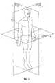
- FIG. 1is a diagram of the three reference planes of the human body.
- FIG. 2Ais a side view of a portion of a human spine illustrating certain conditions.
- FIG. 2Bis a perspective view of a single human spinal vertebrae and the nearby spinal cord and nerves.
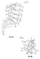
- FIGS. 3A-3Bare perspective views of an exemplary embodiment of the spinous process device according to certain aspects of this disclosure.
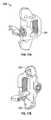
- FIGS. 4A-4Dillustrate an exemplary insertion tool for use with the device of FIGS. 3A-3B according to certain aspects of this disclosure.
- FIGS. 5A-5Billustrate the operation of the tool of FIGS. 4A-4B to increase the separation of the two separation bars of the device of FIGS. 4A-4D .
- FIG. 6Ais an exploded view of the device of FIGS. 3A-3B according to certain aspects of this disclosure.
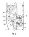
- FIGS. 6B-6Cdepict an exemplary clamping feature of the first element of the spinous process device according to certain aspects of this disclosure.
- FIG. 6Cis a partial cross-section of the first element taken along the line C-C shown in FIG. 6B .
- FIGS. 7 and 8illustrate how the two elements of the device of FIGS. 4A-4D adjust while clamping adjacent spinous processes.
- FIG. 9Aillustrates another embodiment of a spinous process device according to certain aspects of this disclosure.
- FIG. 9Billustrates an insertion tool adapted for use with the device of FIG. 9A according to certain aspects of this disclosure.
- FIG. 10illustrates another embodiment of a spinous process device according to certain aspects of this disclosure.
- FIGS. 11A-11Bare perspective views of another embodiment of a spinous process device according to certain aspects of this disclosure.
- FIGS. 12A-12Care perspective views of another embodiment of a spinous process device according to certain aspects of this disclosure.
- FIG. 12Dillustrates an installation tool adapted for use with the devices of FIGS. 12A-12C .
- FIGS. 13A-13Bare perspective views of another embodiment of a spinous process device according to certain aspects of this disclosure.
- FIGS. 14A-14Bare perspective views of another embodiment of a spinous process device according to certain aspects of this disclosure.
- FIGS. 15A-15Care perspective views of another embodiment of a spinous process device according to certain aspects of this disclosure.
- FIGS. 16A-16Care perspective views of another embodiment of a spinous process device according to certain aspects of this disclosure.
- FIGS. 17A-17Bare perspective views of another embodiment of a spinous process element according to certain aspects of this disclosure.
- FIGS. 18A-18Bare perspective views of the spinous process device formed from two of the elements of FIGS. 17A-17B according to certain aspects of this disclosure.
- FIG. 19illustrates an exemplary embodiment of an installation tool adapted for use with the devices of FIGS. 18A-18B according to certain aspects of this disclosure.
- FIG. 20illustrates another embodiment of an installation tool adapted for use with the device of FIGS. 18A-18B according to certain aspects of this disclosure.
- the following descriptiondiscloses embodiments of a spinous process device that provides an adjustable spacer between the spinous processes of adjacent vertebrae as well as clamping the two spinous processes between two plates so as to immobilize the vertebrae.
- the disclosed systemprovides a spinous process device with an adjustable spacing capability.
- the devicecan be installed when there is a narrow gap between adjacent spinous processes and expanded after the spinous processes are separated to the desired positions.
- the resultis a single device that can both provide an adjustable amount of spacing between spinous processes and then clamp the spinous processes in place.
- the phrase “continuously adjustable”means that adjustment can be made to any point within a range of adjustment rather than being restricted to selection from a set of discrete separate alternatives.
- the relative orientation of two toothed gears engaged with each otheris not continuously adjustable as the engagement of the gears must shift in increments of a full tooth.
- the position of a coin lying flat on a flat horizontal tabletopcan be continuously adjusted by any distance, small or large, within the bounds of the tabletop.
- translationand similar terms mean movement of an item in one or more of the three spatial dimensions without rotation of the item.
- clamping featuremeans a mechanism or component that is capable of immobilizing one or more secondary elements in both translation and rotation with respect to a primary element.
- a clamping featuremay also be referred to herein as a “locking feature” and the terms “clamp” and “lock” and the like are considered equivalent herein.
- a clamping featuremay have a “free” or “unlocked” configuration that allows one or more of the secondary elements to move with respect to the primary element, and may also have a “clamped” or “locked” configuration wherein the secondary elements immobilize one or more secondary elements in both translation and rotation with respect to a primary element.
- any of the terms “activating,” “actuating,” “locking,” and the like with respect to a clamping featuremeans changing the configuration of the clamping feature to the locked configuration
- use of any of the terms “deactivating,” “unlocking,” “releasing,” and the like with respect to the clamping featuremeans changing the configuration of the clamping feature to the unlocked configuration
- Use of the phrase “moving between” and the like with respect to a clamping featuremeans changing the configuration of the clamping feature from one of the locked and unlocked configurations to the other of the locked and unlocked configurations.
- FIG. 1is a diagram of the three reference planes of the human body 1 . These three planes include the coronal, or frontal, plane 6 , which passes from left to right through the body. The sagittal, or lateral, plane 2 passes from front to back. The transverse, or axial, plane 4 passes horizontally through the body 1 of a standing person.
- FIG. 2Ais a side view of a portion of a human spine 10 illustrating certain conditions.
- This portionincludes the lumbar vertebrae L2-L5 and the sacrum 13 .
- Each vertebrae 20has a central flange 16 that is called a “spinous process.”
- vertebra L3has a spinous process 16 A
- vertebra L2has a spinous process 16 B that is adjacent to spinous process 16 A.
- Healthy intervertebral discs 22are shown between vertebrae L2 and L3 and compressed discs 24 are shown between vertebrae L3 and L4 and between vertebrae L4 and L5.
- the spinal cord 12passes through openings in the vertebrae and a healthy spinal nerve 30 is shown branching off from the spinal cord 12 and passing between vertebrae L2 and L3.
- the compression of disc 24 between vertebrae L4 and L5has narrowed the gap through which the spinal nerve 32 is passing thereby pinching spinal nerve 32 , a condition called lumbar spinal stenosis.
- the L5 vertebrain this example, is displaced from its normal position, a condition called spondylolisthesis. This has resulted in the disc 26 becoming squeezed toward one side and, as can be seen, the disc 26 is bulging outward compared to the healthy discs 22 .
- FIG. 2Bis a perspective view of a single human spinal vertebra 20 and the nearby spinal cord 12 and nerves 30 .
- the vertebra 20includes a body 18 and a central spinous process 16 , with the spinal nerve 30 passing through a gap 14 .
- FIGS. 3A-3Bare perspective views of an exemplary embodiment of a spinous process device 100 according to certain aspects of this disclosure.
- the device 100may comprise a first element 105 comprising a first plate 106 configured to overlap one of the left and right sides of the adjacent spinous processes 16 , for example spinous processes 16 A and 16 B of FIG. 2A .
- the first plate 106may have two gripping sides that each have gripping surfaces 114 and a first separation bar 108 fixedly coupled to the first plate 106 and projecting approximately orthogonal to the gripping surfaces 114 .
- the device 100may also include a spacer element 120 comprising an adjustment bar 122 and a second separation bar 124 fixedly coupled to the adjustment bar 122 and projecting approximately orthogonal to the adjustment bar 122 .
- the device 100may also include a second element 110 comprising a second plate 112 configured to overlap the other of the left and right sides of the adjacent spinous processes 16 .
- the second plate 112may have gripping surfaces 114 and a receptacle 117 ( FIG. 6A ) configured to accept the first separation bar 108 .
- the second element 110may also have a channel 126 configured to slidably accept the spacer element 120 such that the second separation bar 124 projects approximately orthogonal to the gripping surface(s) 114 of the second element 110 .
- the second element 110may also include a clamping, or locking, feature 116 coupled to the plate 112 .
- the clamping feature 116is configured to loosely capture one or both of the adjustment bar 122 and the separation bar 108 when the clamping feature is in an unlocked configuration and to lock both the adjustment bar 122 and the separation bar 108 when the clamping feature 116 is actuated.
- the clamping feature 116is discussed in greater detail with respect to FIGS. 6A-6C .
- the gripping surfaces 114 of first and second elements 105 , 110may each include one or more surfaces.
- spikes 114 Aare disposed over a portion of the gripping side.
- the spikes 114 Acan have multiple facets and be formed in the shape of pyramids of various heights. In some embodiments, these spikes 114 A may have other shapes, such as cones, hemispheres, planar teeth, and such.
- the some or all of the spikes 114 Ae.g.
- the gripping surface 114can comprise the facets of spikes 114 A. In some instances, the spinous process 16 may contact only a portion of the gripping surface 114 .
- the separation bars 108 and 124have a distance between them that is adjustable. Separation bars 108 and 124 can be brought close together to provide a low profile cross element that can be introduced into a minimum of space between spinous processes 16 of adjacent vertebrae 20 . This may facilitate placement of the spinous process device 100 as the shape of spinous processes 16 creates a reduced gap between the tips of adjacent spinous processes 16 when the spacing between adjacent vertebrae is reduced, as shown in FIG. 2A for vertebrae L4 and L5. This may be particularly advantageous when adjacent vertebrae 20 have shifted or an inter-vertebral disk 24 has collapsed and the space between the adjacent spinous processes 16 is less than normal.
- the separation bars 108 and 124can be distracted, i.e. separated, such as when the implant 10 is in place within the larger gap between adjacent spinous processes 16 closer to the body 18 of vertebrae 20 , or when the spinous processes 16 themselves have been separated, or to cause the spinous processes 16 to separate.
- the distance between first element 105 and second element 110may also be adjustable.
- First element 105may have a window 107 therethrough suitable for separation bar 124 to pass through.
- Second element 110may have a window 113 therethrough suitable for one or both of separation bar 108 and separation bar 124 to pass through.
- Such windowsmay have sufficiently close clearance with respective separation bars 108 , 124 so as to limit certain degrees of freedom of motion, such as rotation, or alternatively may have a more wide-open clearance.
- Second element 110may have receptacle 117 , which may comprise a specially shaped contour of a portion of the window through second element 110 .
- Receptacle 117may have a shape that may be complementary in shape to separation bar 108 , such as a portion of a rounded rectangle for example, and have a desired clearance with respect to separation bar 108 .
- Second element 110may have channel 126 , which may extend in a direction generally from spinous process 16 A to spinous process 16 B when arranged as shown in FIGS. 7 and 8 for example.
- Channel 126may be configured to receive and guide adjustment bar 122 .
- Adjustment bar 122may have, in at least some places, a cross-sectional shape that is non-circular such as having a flat 123 . Such shape may serve either to limit rotation of adjustment bar 122 or to provide a flat space upon which clamping feature 116 such as a setscrew may bear.
- Adjustment bar 122 and separation bar 124 or bothmay cooperate with channel 126 to guide or limit the motion of adjustment bar 122 and separation bar 124 , such as to limit rotation thereof about any axis.
- Adjustment bar 122may be approximately perpendicular to separation bar 124 although this is not essential.
- the adjustment bar 122 and the separation bar 124can be arranged in some embodiments such that angles greater or less than 90 degrees are formed between them.
- clamping feature 116may comprise a through-hole 119 through which adjustment bar 122 may fit, and may comprise a hole 121 that accepts a setscrew 118 , and the hole 119 and the through-hole 121 may intersect.
- Various componentsmay have features that prevent disassembly.
- adjustment bar 122may have at one end a feature that prevents adjustment bar 122 from sliding completely through clamping feature 116 .
- Such featuremay arise from the feature that flat 123 may extend for less than the full length of adjustment bar 122 .
- the flat 123can terminate at a location 123 A that is spaced from an end of the adjustment bar 122 .
- Separation bar 124may have at its end a feature that prevents it from sliding through first element 105 .
- Separation bar 108may have at its end a feature that prevents it from sliding through second element 110 . Any surface of any component that bears against another surface when the clamping feature 116 is in its locked configuration may be textured in some embodiments.
- Either or both of separation bars 108 , 124may have a slot or one or more holes therethrough, which may be oriented in a direction that is generally parallel to the direction from spinous process 16 A to spinous process 16 B when the device and spinous processes are arranged as shown in FIGS. 7 and 8 .
- Such hole(s) or slotmay be suitable to allow growth of bone therethrough.
- First element 105 and second element 110may have gripping surfaces 114 , which may comprise any of various forms of spikes, ridges, grooves, roughness, and similar features and combinations thereof to aid in gripping bone, such as spinous processes 16 .
- Adjustment bar 122 and separation bar 124may be either joined to each other after separate manufacture or manufactured integrally with each other.
- First element 105 and separation bar 108may be either joined to each other after separate manufacture or manufactured integrally with each other.
- FIGS. 4A-4Dillustrate an exemplary insertion tool 200 for use with the spinous process device 100 of FIGS. 3A-3B according to certain aspects of this disclosure.
- the illustrated tool 200comprises a first arm 210 configured to engage one of the first and second elements 105 , 110 of the device 100 and a second arm 220 coupled to the first arm 210 .
- the second arm 220is configured to engage the other of the first and second elements 105 , 110 of the device 100 .
- the first and second arms 210 , 220are configured to hold the first and second elements 105 , 110 approximately parallel to each other at a first separation distance and, when actuated, to displace the first and second elements 105 , 110 towards each other.
- the first and second arms 210 , 220are configured to hold the first and second elements 105 , 110 at an angle to each other within an angular range and to selectably adjust an average distance between the first and second elements 105 , 110 .
- the tool 200can also include a third arm 230 coupled to one of the first and second arms 210 , 220 .
- the third arm 230is configured to selectably separate the first and second separation bars 108 , 124 .
- FIG. 4Bprovides an enlarged view of the engagement of the tool 200 with a spinous process device 100 from a reverse angle.
- the first and second arms 210 , 220can be seen to have C-shaped ends that engage features, e.g. holes in the first and second plates 106 , 122 .
- FIG. 4Cis an enlarged view of the engagement of the tool 200 with a spinous process device 100 from yet another angle that makes visible the engagement of third arm 230 with the first and second separation bars 108 , 124 . Rotation of the third arm 230 will move the separation bar 124 of spacer element 120 away from the separation bar 108 .
- FIG. 4Dillustrates the quasi-spherical joint 240 between the first and second arms 210 , 220 that, in this embodiment, allows the arms to rotate with respect to each other not only about a vertical axis, as seen in this view, through the joint 240 but also around a longitudinal axis generally aligned with the long dimensions of the two arms 210 , 220 .
- Thisallows the first and second elements 105 , 110 to rotate relative to each other as they are brought together to clamp the spinous processes at an angle, as shown in FIGS. 7 and 8 .
- FIGS. 5A-5Billustrate the operation of the tool of FIGS. 4A-4B to increase the separation of the two separation bars of the device of FIGS. 4A-4D .
- FIG. 5Aillustrates the configuration of device 100 and tool 200 after placing the first element 105 proximate to adjacent spinous processes 30 with the separation bar 108 passing through a gap between the adjacent spinous processes (not shown in FIGS. 5A-5B ) and placing the second element 110 proximate to the adjacent spinous processes such that the separation bar 108 is accepted by the receptacle, and also placing the spacer element 120 such that the separation bar 124 passes through the gap between the adjacent spinous processes and the adjustment bar 122 is accepted by a channel 126 in the second element 110 .
- FIG. 5Billustrates the configuration of the device 100 and tool 200 sliding the spacer element 120 relative to the second element 110 such that the separation of the separation bars 108 , 124 is increased.
- the clamping feature 116 of the second element 110would be activated in the configuration of FIG. 5B to clamp or lock both the adjustment bar 122 and the separation bar 108 .
- the device 100is not used to distract, or separate, the two spinous processes 16 .
- the device 100is installed in a collapsed configuration for ease of insertion and then expanded to fill a gap previously created by the surgeon between the adjacent spinous processes 16 .
- the device 100is inserted between the spinous processes 16 prior to distraction, the two spinous processes 16 are then distracted using a different tool (not shown), and the device 100 expanded.
- the device 100is used to provide the distraction of the spinous processes 16 .
- the device 100may be inserted installed in a collapsed configuration between adjacent spinous processes 16 using the tool 200 .
- the tool 200may then be manipulated to distract the separation bars 108 and 124 and thereby distract the adjacent spinous processes 16 .
- the tool 200may be used to assist the operation of a different distraction tool (not shown).
- FIG. 6Ais an exploded view of the device 100 of FIGS. 3A-3B according to certain aspects of this disclosure.
- the receptacle 117 that accepts the first separation bar 108is visible.
- the adjustment bar 122comprises a flat 123 .
- An axis 116 Ais defined for the clamping, or locking, feature 116 .
- FIG. 6Aalso includes a set of reference axes and general directions that are appropriate for a typical orientation of the spinous process device 100 when used to stabilize adjacent spinous processes 16 .
- the superior-inferior axis, the posterior-anterior axis, and the left-right axisare oriented perpendicular to each other.
- the axesare provided solely for convenience in discussion of directions of the orientation of various elements and features of the spinous process device 100 within this application. Depiction of any device, or any element or feature thereof, does not restrict the possible positions or orientations of the device, element, or feature and does not restrict the use of any device to an orientation disclosed herein.
- the longest dimensions of elements 105 , 110are generally parallel with the superior-inferior axis
- the longest dimensions of the separation bars 108 , 124are generally parallel with the left-right axis
- the axis 116 Ais generally parallel to the posterior-anterior axis.
- FIGS. 6B-6Cdepict an exemplary clamping feature 116 of the first element 112 of the spinous process device 100 according to certain aspects of this disclosure.
- FIG. 6Bshows the complete device 100 with a section-line C-C and a dashed-line box “ 6 C” indicating the portion of a cross-sectional view of device 100 that is enlarged in FIG. 6C .
- FIG. 6Cis a partial cross-section through the spinous process device 100 along line C-C showing the clamping feature 116 .
- the illustrated clamping feature 116has a set screw 118 that bears on the flat 123 of the adjustment bar 122 of the spacer element 120 .
- setscrew 118may bear against adjustment bar 122 , such as against flat 123 of adjustment bar 122
- adjustment bar 122in turn may bear against separation bar 108 , which in turn may bear against a surface of second element 110 such as receptacle 117 .
- FIGS. 7 and 8illustrate how the two elements 105 , 110 of the device 100 of FIGS. 4A-4D adjust while clamping adjacent spinous processes 16 A, 16 B.
- the two plates 106 , 112are approximately parallel and therefore the separation bars 108 , 124 are also approximately parallel.
- the lower spinous process 16 Ais thinner in the area gripped by the plates 106 , 112 that the upper spinous process 16 B.
- the two plates 106 , 112rotate with respect to each other as they are brought together.
- the separation bars 108 , 124remain approximately perpendicular, in this embodiment, to the respective plates 106 , 112 .
- the spacer element 120can still be moved, however, in the channel 126 of the element 110 so that both separation bars 108 , 124 are in contact with the respective spinous processes 16 A, 16 B.
- the separation bars 108 and 124can be either parallel to each other or non-parallel to each other, and the plates 106 , 112 can be either parallel to each other or non-parallel to each other.
- the clamping feature 116is locked, the separation bars 108 and 124 can be either parallel to each other or non-parallel to each other, and the plates 106 , 112 can be either parallel to each other or non-parallel to each other.
- the device 100is capable of being locked in either a configuration wherein the plates and/or separation bars are parallel or in a configuration wherein they are nonparallel.
- FIG. 9Aillustrates another embodiment of a spinous process device 130 according to certain aspects of this disclosure.
- the device 130has a first element 132 with a connection bar 134 that projects orthogonally from a gripping plate 133 .
- the device 130also has a second element 135 with a second gripping plate 138 with a passage 136 configured to receive the connection bar 134 .
- Element 135also has a clamping feature 137 configured to clamp or lock the connection bar 134 when actuated.
- FIG. 9Billustrates an insertion tool 140 adapted for use with the device 130 of FIG. 9A according to certain aspects of this disclosure.
- the tool 140has two handles 142 that couple to the first and second elements 132 , 135 of device 130 .
- the tool 140also includes an alignment block 143 that assists in providing the proper spacing of the first and second elements 132 , 135 as the second element 135 is introduced during implantation.
- FIG. 10illustrates another embodiment of a spinous process device 150 according to certain aspects of this disclosure.
- the device 150has a first element 152 with a slot 153 and a second element 154 with a slot 156 .
- a connection bar 155is configured to bridge the distance between elements 152 , 154 .
- a nut 158is attached to the connection bar 155 at one end, wherein the connection bar 155 includes a feature (not visible in FIG. 10 ) that locks the connection bar to the slot 153 when the nut 158 is tightened.
- the second element 154has a clamping feature 157 that locks the other end of connection bar 155 to the slot 156 when the clamping feature 157 is actuated.
- connection bar 155has horizontal grooves.
- the mating rear surface (not visible in FIG. 10 ) of connection bar 155has complementary horizontal grooves.
- the front surface of connection bar 155can be seen to have vertical grooves and the mating rear surface (not visible in FIG. 10 ) of clamping feature 157 has complementary vertical grooves. Then the clamping feature 157 is tightened, the vertical grooves on the back of the clamping feature 157 engage the vertical grooves of the connection bar 155 and displace connection bar 155 such that the horizontal grooves on the back of the connection bar 155 engage the horizontal grooves on slot 156 , thereby locking the connection bar 155 into a fixed position in both the vertical and horizontal directions with respect to the second element 154 .
- the front interior surface (not visible in FIG. 10 ) of slot 153does not have grooves. Tightening of the nut 158 , after the clamping feature 157 is tightened, draws the first element 152 toward the second element 154 until the spinous processes 16 (not shown in FIG. 10 ) are clamped between the elements 153 , 154 , whereupon further tightening of the nut 158 provides clamping pressure on the spinous processes 16 .
- FIGS. 11A-11Bare perspective views of another embodiment of a spinous process device 160 according to certain aspects of this disclosure.
- the device 160has a first element 162 with a slot 163 and a second element 164 with a slot 166 .
- a connection bar 165is configured to bridge the distance between elements 162 , 164 .
- a nut 168is attached to the connection bar 165 at one end, wherein the connection bar 165 includes a feature 169 that locks the connection bar 165 to the slot 163 when the nut 168 is tightened.
- the second element 164has a clamping feature 167 that locks the other end of connection bar 165 to the slot 166 when the clamping feature 167 is actuated.
- Slot 166 , connection bar 165 , and clamping feature 167have grooves disposed similar to those of device 150 in FIG. 10 , and tightening of clamping feature 167 followed by tightening of nut 168 will accomplish locking and clamping actions similar to those described for device 150 .
- FIGS. 12A-12Care perspective views of another embodiment of a spinous process device 170 according to certain aspects of this disclosure.
- the device 170has a first element 172 and a second element 174 with a slot 176 .
- a connection bar 175is configured to bridge the distance between elements 172 , 174 and fit into the slot 176 .
- the connection bar 175has a clamping feature 177 that locks the connection bar 175 to the first element 172 when the clamping feature 177 is actuated.
- the second element 176has a feature (not visible) that interlocks with the first element 172 at the bottom to hold the bottom of element 174 in place after the clamping feature 177 is tightened.
- FIG. 12Dillustrates a device 180 that is similar to device 170 of FIGS. 12A-12C .
- the device 180has a first element 182 and a second element 184 with a slot 186 .
- the first element 182includes a post 181 that bridges the distance between elements 182 , 184 and fit into the slot 186 .
- the device 180includes a connection element 185 with a bridging post 189 that fits into a notch that is part of slot 186 .
- the connection element 185also has a clamping feature 187 that locks the connection element 185 to the first element 182 when the clamping feature 187 is actuated.
- a tool 188attaches to the connection element 185 and comprises a toothed wheel (not visible in FIG. 12D ) that engages the toothed surface visible on the side of first element 182 and, when activated, distracts the bridging post 189 of the connection element 185 vertically from the bridging post 181 of the first element 182 .
- FIGS. 13A-13Bare perspective views of another embodiment of a spinous process device 190 according to certain aspects of this disclosure.
- the device 190has a first element 192 with a slot 193 and a second element 194 with slots 196 A and 196 B.
- the first element 192includes a bar 191 that bridges the distance between elements 192 , 194 and fit into the slot 196 B.
- the device 190also has a connection bar 195 that also bridges the distance between the elements 192 , 194 and fits into the slots 193 and 196 A at each end.
- the first element 192has a clamping feature 197 B that locks one end of connection bar 195 to the slot 193 when the clamping feature 197 B is actuated.
- the second element 194has a clamping feature 197 A that locks the other end of connection bar 195 to the slot 196 A and locks the end of bar 191 to slot 196 B when the clamping feature 197 A is actuated.
- FIGS. 14A-14Bare perspective views of another embodiment of a spinous process device 200 according to certain aspects of this disclosure.
- the device 200has a first element 202 and a second element 204 with slot 206 .
- the first element 202includes a bar 201 that bridges the distance between elements 202 , 204 and fit into the slot 206 .
- the device 200also has a connection bar 205 that also bridges the distance between the elements 202 , 204 and fits through the slot 206 at one end and includes a clamping feature 207 B at the other end that locks that end of connection bar 205 to the first element 202 when the clamping feature 207 B is actuated.
- the device 200also includes a locking element 207 A that locks the other end of the connection bar 205 and prevents the connection bar 205 from being withdrawn from the slot 206 .
- Second element 204also includes a clamping feature 207 C that, when actuated, locks the end of bar 201 to the slot 206 .
- FIGS. 15A-15Care perspective views of another embodiment of a spinous process device 210 according to certain aspects of this disclosure.
- the device 210has a first element 212 and a second element 214 with slot 216 .
- the first element 212includes a post that couples to the second element 214 .
- the device 210also has a sliding element 215 that is slidably coupled to element 212 .
- the device 210also has a clamping bolt 217 that passes through the sliding element 215 and through the slot 216 .
- a nut 218attaches to the end of bolt 217 and, when tightened, clamps the first and second elements 212 , 214 to the spinous processes between them.
- FIGS. 16A-16Care perspective views of another embodiment of a spinous process device 220 according to certain aspects of this disclosure.
- the device 220has a first element 222 with slot 226 and a second element 224 .
- the first element 222includes a post 223 and the second element includes a post 228 .
- the device 220has a bolt 227 that passes through slot 226 and is threaded into the second element 224 and, when actuated, clamps the first and second elements 222 , 224 together.
- the device 210also has a pair of plates 225 A, 225 B that can be slipped over the ends of the posts 228 and 223 , respectively, and be clamped to the posts 228 and 223 , thereby clamping the spinous processes 16 (not shown in FIGS. 16A-16C ) between the plates 225 A, 2258 and the first and second elements 222 , 224 .
- FIGS. 17A-17Bare perspective views of another embodiment of a spinous process element 252 according to certain aspects of this disclosure.
- a pair of elements 252are used together as shown in FIG. 18A to form a spinous process device 250 .
- Each element 252has a gripping plate 254 with upper and lower profiles with gripping features, for example spikes or angled teeth as shown in FIG. 17B , as well as a slot 256 .
- the element 252also has a connection bar 253 projecting perpendicular to the gripping plate 254 .
- the element 252also includes a clamping feature 257 .
- the connection bar 253can be seen to have vertical grooves on the front face, as oriented in FIGS. 17A-17B , and has horizontal grooves (not visible in FIGS.
- the slot 256can be seen to have horizontal grooves on the rear interior surface while the front interior surface of slot 156 is smooth.
- the clamping feature 257comprises a rear surface (not visible in FIGS. 17A-17B ) that protrudes into slot 256 when actuated.
- the rear surface of clamping feature 257has vertical grooves that engage vertical grooves on the front face of connection bar 253 of a second spinous process element 252 (not shown in FIGS. 17A-17B ) when the clamping feature 257 is tightened.
- FIGS. 18A-18Bare perspective views of the spinous process device 250 formed from two of the spinous process elements 252 of FIGS. 17A-17B according to certain aspects of this disclosure. It can be seen how a first element 252 A is positioned on the right side of the spinous processes and a second element 252 B is positioned in an inverted orientation on the left side.
- the connection bar 253 Athus fits into the slot 256 B where it will be locked by clamping feature 257 B when actuated.
- the connection bar 253 Bfits into slot 256 A and will be locked by clamping feature 257 A.
- FIG. 18Billustrates how multiple devices 250 may be positioned to stabilize adjacent pairs of spinous processes. It can be seen that the upper and lower profiles of the gripping plate 254 are configured such that when element 252 B-UPPER of the upper device 250 -UPPER is adjacent to element 252 B-LOWER of the lower device 250 -LOWER, the adjacent profiles cooperate to allow close mounting of the devices 250 .
- Elements 252 A and 252 Bare shaped to allow a pair of spinous process devices 252 to grip a common spinous process 16 C so as to stabilize adjacent pairs of spinous processes 16 , wherein the elements 252 of the spinous process device 250 each comprise an upper profile and a lower profile such that a top of the first element 252 A-LOWER of a lower spinous process device 250 -LOWER and a bottom of the first element 252 A-UPPER of an upper spinous process device 250 -UPPER can be positioned to grip a first side of the common spinous process 16 C and a top of the second element 252 A-LOWER of the lower spinous process device 250 -LOWER and a bottom of the second element 252 A-UPPER of the upper spinous process device 250 -UPPER can be positioned to grip a second side that is opposite to the first side of the common spinous process 16 C.
- FIG. 19illustrates an exemplary embodiment of an installation tool 260 adapted for use with the device 250 of FIGS. 18A-18B according to certain aspects of this disclosure.
- the tool 260has two posts 262 A and 262 B that engage the clamping features 257 A and 257 B, respectively, of the device 250 .
- the posts 262 A, 262 Bhave drive ends 264 A, 264 B at the opposite ends that allow the clamping features 257 A, 257 B to be actuated by use of a tightening tool (not shown), such as a socket wrench for example.
- the tool 260includes a first slide 267 with an advancement feature 265 A that, when actuated, causes the post 262 A to move along a first axis with respect to post 262 B.
- the tool 260also includes a second slide 268 with advancement feature 265 B that, when actuated, causes the post 262 A to move with respect to post 262 B along a second axis that is perpendicular to the first axis.
- Ratchets 266 A and 266 Brelease the slides 267 , 268 respectively when actuated, thereby allowing the tool 260 to be removed.
- FIG. 20illustrates another embodiment of an installation tool 270 adapted for use with the device 50 of FIGS. 18A-18B according to certain aspects of this disclosure.
- the tool 270includes two handles 272 A, 272 B that have connection tips 274 A, 274 B that are configured to engage attachment features (not shown in FIGS. 18A-18B ) so as to enable a surgeon to use this tool to position the spinous process elements 252 A and 252 B.
- the arms 272 A and 272 Bare coupled together with a mechanism 276 that maintains the lower portions of the arms 272 A, 272 B approximately parallel as the separation between the tips 274 A, 274 B changes. Once separated, the separation of tips 274 A and 274 B can be maintained by actuation of the rod and nut assembly 277 , which can be tightened to hold the upper portions of arms 272 A, 272 B together or at a designated separation distance.
- FIGS. 21A-21Billustrate another embodiment of an installation tool 370 according to certain aspects of this disclosure.
- a first installation tool 370comprises a tip 374 A that engages the clamping feature 257 and also engages the gripping plate 254 of a first spinous process element 252 A to allow control of the orientation of the spinous process element 252 A.
- a tip 374 B of a second tool 370engages the clamping feature 257 and gripping plate 254 of a second spinous process element 252 B.
- the tool 370comprises an internal shaft (not visible in FIGS. 21A-12B ) that allows the surgeon to tighten the clamping features 257 of both spinous process elements 252 A, 252 B while the tool tips 374 A, 374 B are still engaged.
- a first element, a spacer element, and a second element of a spinous process devicecan be assembled prior to implantation.
- the first element, spacer element, and second elementcan be as disclosed herein, thus a further description of them is not repeated here.
- the first separation bar and the adjustment barpass through the locking feature such that the first and second gripping sides or surfaces face each other and the first and second separation bars extend between the first and second gripping sides or surfaces.
- the first and second separation baresare generally parallel to each other in an initial assembled state or as adjusted assembled state.
- the assembled spinous process devicecan have a first distance between the first and second gripping surfaces and a second distance between the first and second separation bars.
- certain embodiments of the disclosed spinous process devicecan be assembled prior to implantation between adjacent spinous processes of different sizes and then adjusted after implantation to securely grip both sides of both adjacent spinous processes as well as a provide positive separation of the adjacent spinous processes.
- the multiple components of certain embodiments of the disclosed spinous process devicescan all be fixedly secured by actuation of a single locking feature. Exemplary tools are disclosed for the manipulation of the disclosed spinous process devices during implantation, adjustment of the relative positions and orientations of the components of the disclosed spinous process device, and actuation of the locking feature.
- topshould be understood as referring to an arbitrary frame of reference, rather than to the ordinary gravitational frame of reference.
- a top surface, a bottom surface, a front surface, and a rear surfacemay extend upwardly, downwardly, diagonally, or horizontally in a gravitational frame of reference.
- angles formed between the referenced componentscan be greater or less than 90 degrees in some embodiments.
- a phrase such as an “aspect”does not imply that such aspect is essential to the subject technology or that such aspect applies to all configurations of the subject technology.
- a disclosure relating to an aspectmay apply to all configurations, or one or more configurations.
- a phrase such as an aspectmay refer to one or more aspects and vice versa.
- a phrase such as an “embodiment”does not imply that such embodiment is essential to the subject technology or that such embodiment applies to all configurations of the subject technology.
- a disclosure relating to an embodimentmay apply to all embodiments, or one or more embodiments.
- a phrase such as an embodimentmay refer to one or more embodiments and vice versa.
Landscapes
- Health & Medical Sciences (AREA)
- Orthopedic Medicine & Surgery (AREA)
- Life Sciences & Earth Sciences (AREA)
- Neurology (AREA)
- Surgery (AREA)
- Heart & Thoracic Surgery (AREA)
- Engineering & Computer Science (AREA)
- Biomedical Technology (AREA)
- Nuclear Medicine, Radiotherapy & Molecular Imaging (AREA)
- Medical Informatics (AREA)
- Molecular Biology (AREA)
- Animal Behavior & Ethology (AREA)
- General Health & Medical Sciences (AREA)
- Public Health (AREA)
- Veterinary Medicine (AREA)
- Surgical Instruments (AREA)
- Prostheses (AREA)
Abstract
Description
Claims (29)
Priority Applications (1)
| Application Number | Priority Date | Filing Date | Title |
|---|---|---|---|
| US13/530,049US9149306B2 (en) | 2011-06-21 | 2012-06-21 | Spinous process device |
Applications Claiming Priority (2)
| Application Number | Priority Date | Filing Date | Title |
|---|---|---|---|
| US201161499633P | 2011-06-21 | 2011-06-21 | |
| US13/530,049US9149306B2 (en) | 2011-06-21 | 2012-06-21 | Spinous process device |
Publications (2)
| Publication Number | Publication Date |
|---|---|
| US20130012996A1 US20130012996A1 (en) | 2013-01-10 |
| US9149306B2true US9149306B2 (en) | 2015-10-06 |
Family
ID=47439113
Family Applications (1)
| Application Number | Title | Priority Date | Filing Date |
|---|---|---|---|
| US13/530,049Active2032-10-23US9149306B2 (en) | 2011-06-21 | 2012-06-21 | Spinous process device |
Country Status (1)
| Country | Link |
|---|---|
| US (1) | US9149306B2 (en) |
Cited By (2)
| Publication number | Priority date | Publication date | Assignee | Title |
|---|---|---|---|---|
| US20180235673A1 (en)* | 2016-02-02 | 2018-08-23 | Globus Medical, Inc. | Expandable spinal fixation system |
| US11432937B1 (en)* | 2021-11-02 | 2022-09-06 | Linares Medical Devices, Llc | Expandable spinal jack for installation between upper and lower succeeding superior articular processes |
Families Citing this family (26)
| Publication number | Priority date | Publication date | Assignee | Title |
|---|---|---|---|---|
| US9055981B2 (en) | 2004-10-25 | 2015-06-16 | Lanx, Inc. | Spinal implants and methods |
| US8241330B2 (en) | 2007-01-11 | 2012-08-14 | Lanx, Inc. | Spinous process implants and associated methods |
| US9265532B2 (en) | 2007-01-11 | 2016-02-23 | Lanx, Inc. | Interspinous implants and methods |
| US9247968B2 (en)* | 2007-01-11 | 2016-02-02 | Lanx, Inc. | Spinous process implants and associated methods |
| US7842074B2 (en) | 2007-02-26 | 2010-11-30 | Abdou M Samy | Spinal stabilization systems and methods of use |
| US9402656B2 (en)* | 2009-09-11 | 2016-08-02 | Globus Medical, Inc. | Spinous process fusion devices |
| US10945858B2 (en)* | 2010-09-03 | 2021-03-16 | Globus Medical, Inc. | Expandable interspinous process fixation device |
| US8876866B2 (en)* | 2010-12-13 | 2014-11-04 | Globus Medical, Inc. | Spinous process fusion devices and methods thereof |
| US20120323276A1 (en)* | 2011-06-17 | 2012-12-20 | Bryan Okamoto | Expandable interspinous device |
| USD757943S1 (en) | 2011-07-14 | 2016-05-31 | Nuvasive, Inc. | Spinous process plate |
| US8882805B1 (en) | 2011-08-02 | 2014-11-11 | Lawrence Maccree | Spinal fixation system |
| US20130158603A1 (en)* | 2011-08-11 | 2013-06-20 | Todd Bjork | Interspinous process spacer |
| EP2755605A4 (en)* | 2011-09-16 | 2015-10-28 | Lanx Inc | SEGMENTED THORN RESIDUE ANCHORING SYSTEM AND USE METHOD THEREFOR |
| US11812923B2 (en) | 2011-10-07 | 2023-11-14 | Alan Villavicencio | Spinal fixation device |
| EP2800532B1 (en) | 2012-01-05 | 2019-12-11 | Lanx, Inc. | Telescoping interspinous fixation device |
| US10448977B1 (en) | 2012-03-31 | 2019-10-22 | Ali H. MESIWALA | Interspinous device and related methods |
| US8771277B2 (en) | 2012-05-08 | 2014-07-08 | Globus Medical, Inc | Device and a method for implanting a spinous process fixation device |
| US9486251B2 (en) | 2012-12-31 | 2016-11-08 | Globus Medical, Inc. | Spinous process fixation system and methods thereof |
| US9198697B2 (en)* | 2013-03-13 | 2015-12-01 | Globus Medical, Inc. | Spinous process fixation system and methods thereof |
| US9480502B2 (en)* | 2013-05-16 | 2016-11-01 | Smokey Mountain Spine, Llc | Expansion interspinous fixation device and method |
| US9259249B2 (en)* | 2013-11-26 | 2016-02-16 | Globus Medical, Inc. | Spinous process fixation system and methods thereof |
| DE102014102200A1 (en)* | 2014-02-20 | 2015-08-20 | Aesculap Ag | Implant for the stabilization of spinous processes and medical instruments |
| US9603637B2 (en)* | 2014-06-06 | 2017-03-28 | Aurora Spine, Inc. | Polyaxial interspinous fusion implant and bone growth stimulation system |
| US20160278820A1 (en)* | 2015-03-26 | 2016-09-29 | Warsaw Orthopedic, Inc. | Spinal implant system and method |
| EP3365200A4 (en)* | 2015-10-24 | 2019-03-27 | Unifrax I LLC | Inflation gas deflector for automotive airbag assembly |
| US10335207B2 (en) | 2015-12-29 | 2019-07-02 | Nuvasive, Inc. | Spinous process plate fixation assembly |
Citations (223)
| Publication number | Priority date | Publication date | Assignee | Title |
|---|---|---|---|---|
| US5102412A (en) | 1990-06-19 | 1992-04-07 | Chaim Rogozinski | System for instrumentation of the spine in the treatment of spinal deformities |
| US5454812A (en) | 1993-11-12 | 1995-10-03 | Lin; Chih-I | Spinal clamping device having multiple distance adjusting strands |
| US5496318A (en) | 1993-01-08 | 1996-03-05 | Advanced Spine Fixation Systems, Inc. | Interspinous segmental spine fixation device |
| US5810815A (en) | 1996-09-20 | 1998-09-22 | Morales; Jose A. | Surgical apparatus for use in the treatment of spinal deformities |
| US5836948A (en) | 1997-01-02 | 1998-11-17 | Saint Francis Medical Technologies, Llc | Spine distraction implant and method |
| US6048342A (en) | 1997-01-02 | 2000-04-11 | St. Francis Medical Technologies, Inc. | Spine distraction implant |
| US6068630A (en) | 1997-01-02 | 2000-05-30 | St. Francis Medical Technologies, Inc. | Spine distraction implant |
| US6152926A (en) | 1997-01-02 | 2000-11-28 | St. Francis Medical Technologies, Inc. | Spine distraction implant and method |
| US6183471B1 (en) | 1997-01-02 | 2001-02-06 | St. Francis Medical Technologies, Inc. | Spine distraction implant and method |
| US6364883B1 (en) | 2001-02-23 | 2002-04-02 | Albert N. Santilli | Spinous process clamp for spinal fusion and method of operation |
| US6451019B1 (en) | 1998-10-20 | 2002-09-17 | St. Francis Medical Technologies, Inc. | Supplemental spine fixation device and method |
| US6514256B2 (en) | 1997-01-02 | 2003-02-04 | St. Francis Medical Technologies, Inc. | Spine distraction implant and method |
| US6582433B2 (en) | 2001-04-09 | 2003-06-24 | St. Francis Medical Technologies, Inc. | Spine fixation device and method |
| US6652527B2 (en) | 1998-10-20 | 2003-11-25 | St. Francis Medical Technologies, Inc. | Supplemental spine fixation device and method |
| US6695842B2 (en) | 1997-10-27 | 2004-02-24 | St. Francis Medical Technologies, Inc. | Interspinous process distraction system and method with positionable wing and method |
| US6712819B2 (en) | 1998-10-20 | 2004-03-30 | St. Francis Medical Technologies, Inc. | Mating insertion instruments for spinal implants and methods of use |
| US6796983B1 (en) | 1997-01-02 | 2004-09-28 | St. Francis Medical Technologies, Inc. | Spine distraction implant and method |
| US6902566B2 (en) | 1997-01-02 | 2005-06-07 | St. Francis Medical Technologies, Inc. | Spinal implants, insertion instruments, and methods of use |
| US7029473B2 (en) | 1998-10-20 | 2006-04-18 | St. Francis Medical Technologies, Inc. | Deflectable spacer for use as an interspinous process implant and method |
| US7029472B1 (en) | 1999-06-01 | 2006-04-18 | Fortin Frederic | Distraction device for the bones of children |
| US7087083B2 (en) | 2001-03-13 | 2006-08-08 | Abbott Spine | Self locking fixable intervertebral implant |
| US7101375B2 (en) | 1997-01-02 | 2006-09-05 | St. Francis Medical Technologies, Inc. | Spine distraction implant |
| US7189234B2 (en) | 1998-10-20 | 2007-03-13 | St. Francis Medical Technologies, Inc. | Interspinous process implant sizer and distractor with a split head and size indicator and method |
| US7201751B2 (en) | 1997-01-02 | 2007-04-10 | St. Francis Medical Technologies, Inc. | Supplemental spine fixation device |
| US7255714B2 (en) | 2003-09-30 | 2007-08-14 | Michel H. Malek | Vertically adjustable intervertebral disc prosthesis |
| US7306628B2 (en) | 2002-10-29 | 2007-12-11 | St. Francis Medical Technologies | Interspinous process apparatus and method with a selectably expandable spacer |
| US7318825B2 (en) | 2003-12-22 | 2008-01-15 | Life Spine Llc | Dynamic cervical plates and cervical plate constructs |
| US20080021466A1 (en) | 2006-07-20 | 2008-01-24 | Shadduck John H | Spine treatment devices and methods |
| US7335203B2 (en) | 2003-02-12 | 2008-02-26 | Kyphon Inc. | System and method for immobilizing adjacent spinous processes |
| US20080065214A1 (en) | 2002-10-29 | 2008-03-13 | Zucherman James F | Interspinous process implants and methods of use |
| US20080065086A1 (en) | 1997-01-02 | 2008-03-13 | Zucherman James F | Spine distraction implant and method |
| US20080071378A1 (en) | 1997-01-02 | 2008-03-20 | Zucherman James F | Spine distraction implant and method |
| US20080071280A1 (en) | 2004-04-28 | 2008-03-20 | St. Francis Medical Technologies, Inc. | System and Method for Insertion of an Interspinous Process Implant that is Rotatable in Order to Retain the Implant Relative to the Spinous Processes |
| US20080071380A1 (en) | 2006-09-19 | 2008-03-20 | Thomas Sweeney | Systems and Methods for Percutaneous Placement of Interspinous Process Spacers |
| US20080082172A1 (en) | 2006-09-29 | 2008-04-03 | Jackson Roger P | Interspinous process spacer |
| US20080086212A1 (en) | 1997-01-02 | 2008-04-10 | St. Francis Medical Technologies, Inc. | Spine distraction implant |
| US20080097441A1 (en)* | 2004-10-20 | 2008-04-24 | Stanley Kyle Hayes | Systems and methods for posterior dynamic stabilization of the spine |
| US20080108990A1 (en) | 2006-11-02 | 2008-05-08 | St. Francis Medical Technologies, Inc. | Interspinous process implant having a fixed wing and a deployable wing and method of implantation |
| US20080114455A1 (en) | 2006-11-15 | 2008-05-15 | Warsaw Orthopedic, Inc. | Rotating Interspinous Process Devices and Methods of Use |
| US20080161818A1 (en) | 2005-02-08 | 2008-07-03 | Henning Kloss | Spinous Process Distractor |
| US20080167657A1 (en) | 2006-12-31 | 2008-07-10 | Stout Medical Group, L.P. | Expandable support device and method of use |
| US20080167655A1 (en) | 2007-01-05 | 2008-07-10 | Jeffrey Chun Wang | Interspinous implant, tools and methods of implanting |
| US20080177272A1 (en) | 2005-03-21 | 2008-07-24 | Zucherman James F | Interspinous process implant having deployable wing and method of implantation |
| US20080177312A1 (en) | 2006-12-28 | 2008-07-24 | Mi4Spine, Llc | Interspinous Process Spacer Device |
| US20080177298A1 (en) | 2006-10-24 | 2008-07-24 | St. Francis Medical Technologies, Inc. | Tensioner Tool and Method for Implanting an Interspinous Process Implant Including a Binder |
| US20080177306A1 (en) | 2004-10-25 | 2008-07-24 | Lanx, Inc. | Spinal implants and methods |
| US20080183209A1 (en) | 2005-09-23 | 2008-07-31 | Spinal Kinetics, Inc. | Spinal Stabilization Device |
| US20080183211A1 (en)* | 2007-01-11 | 2008-07-31 | Lanx, Llc | Spinous process implants and associated methods |
| US20080221692A1 (en) | 2002-10-29 | 2008-09-11 | Zucherman James F | Interspinous process implants and methods of use |
| US20080243250A1 (en) | 2007-03-26 | 2008-10-02 | Seifert Jody L | Lateral Spinous Process Spacer |
| US20080243254A1 (en) | 2007-03-29 | 2008-10-02 | Butler Michael S | Height adjustable spinal prostheses |
| US20080262619A1 (en) | 2007-04-18 | 2008-10-23 | Ray Charles D | Interspinous process cushioned spacer |
| US20080281360A1 (en) | 2007-05-10 | 2008-11-13 | Shannon Marlece Vittur | Spinous process implants and methods |
| US20080294199A1 (en) | 2007-05-25 | 2008-11-27 | Andrew Kohm | Spinous process implants and methods of using the same |
| US20090005873A1 (en) | 2007-06-29 | 2009-01-01 | Michael Andrew Slivka | Spinous Process Spacer Hammock |
| US20090018658A1 (en) | 2006-08-09 | 2009-01-15 | Nuvasive, Inc. | Methods and apparatus for treating spinal stenosis |
| US7481839B2 (en) | 2003-12-02 | 2009-01-27 | Kyphon Sarl | Bioresorbable interspinous process implant for use with intervertebral disk remediation or replacement implants and procedures |
| US20090062918A1 (en) | 2007-08-30 | 2009-03-05 | Jeffrey Chun Wang | Interspinous implant, tools and methods of implanting |
| US7520888B2 (en) | 2006-02-14 | 2009-04-21 | Warsaw Orthopedic, Inc. | Treatment of the vertebral column |
| US7520887B2 (en) | 2003-02-19 | 2009-04-21 | Warsaw Orthopedic, Inc. | Interspinous device for impeding the movements of two successive vertebrae, and method for making a pad designed for it |
| US20090105773A1 (en) | 2007-10-23 | 2009-04-23 | Warsaw Orthopedic, Inc. | Method and apparatus for insertion of an interspinous process device |
| US7524324B2 (en) | 2004-04-28 | 2009-04-28 | Kyphon Sarl | System and method for an interspinous process implant as a supplement to a spine stabilization implant |
| US20090118833A1 (en) | 2007-11-05 | 2009-05-07 | Zimmer Spine, Inc. | In-situ curable interspinous process spacer |
| US20090125030A1 (en) | 2006-10-18 | 2009-05-14 | Shawn Tebbe | Dilator |
| US20090138046A1 (en) | 2004-10-20 | 2009-05-28 | Moti Altarac | Interspinous spacer |
| US20090138055A1 (en) | 2004-10-20 | 2009-05-28 | Moti Altarac | Spacer insertion instrument |
| US7549999B2 (en) | 2003-05-22 | 2009-06-23 | Kyphon Sarl | Interspinous process distraction implant and method of implantation |
| US20090198338A1 (en) | 2008-02-04 | 2009-08-06 | Phan Christopher U | Medical implants and methods |
| US20090198241A1 (en) | 2008-02-04 | 2009-08-06 | Phan Christopher U | Spine distraction tools and methods of use |
| US20090198277A1 (en) | 2007-12-28 | 2009-08-06 | Osteomed Spine, Inc. | Bone tissue fixation device and method |
| US20090222043A1 (en) | 2004-10-20 | 2009-09-03 | Moti Altarac | Interspinous process spacer instrument system with deployment indicator |
| US7585313B2 (en) | 2005-12-22 | 2009-09-08 | Depuy Spine, Inc. | Rotatable interspinous spacer |
| US7585316B2 (en) | 2004-05-21 | 2009-09-08 | Warsaw Orthopedic, Inc. | Interspinous spacer |
| US7588591B2 (en)* | 2003-10-30 | 2009-09-15 | Synthesis Usa, Llc | Intervertebral implant |
| US7591851B2 (en) | 2004-12-13 | 2009-09-22 | Kyphon Sarl | Inter-cervical facet implant and method |
| US7611526B2 (en) | 2004-08-03 | 2009-11-03 | K Spine, Inc. | Spinous process reinforcement device and method |
| US20090281628A1 (en) | 2008-04-08 | 2009-11-12 | Jean-Francois Oglaza | Apparatus for restoration of the spine and methods of use thereof |
| US20090297603A1 (en) | 2008-05-29 | 2009-12-03 | Abhijeet Joshi | Interspinous dynamic stabilization system with anisotropic hydrogels |
| US7635380B2 (en) | 2007-06-05 | 2009-12-22 | Spartek Medical, Inc. | Bone anchor with a compressor element for receiving a rod for a dynamic stabilization and motion preservation spinal implantation system and method |
| US20090326592A1 (en) | 2008-06-27 | 2009-12-31 | Butler Michael S | Posterior Spinal Prosthesis |
| US20100042151A1 (en) | 2006-05-23 | 2010-02-18 | Warsaw Orthopedic, Inc. | Surgical spacer |
| US20100049251A1 (en) | 2008-03-28 | 2010-02-25 | Kuslich Stephen D | Method and device for interspinous process fusion |
| US20100069961A1 (en) | 2006-02-17 | 2010-03-18 | Zimmer Spine, Inc. | Systems and methods for reducing adjacent level disc disease |
| US7682376B2 (en) | 2006-01-27 | 2010-03-23 | Warsaw Orthopedic, Inc. | Interspinous devices and methods of use |
| US20100076492A1 (en) | 2005-05-02 | 2010-03-25 | Evolution Spine Technologies, Llc. | Spinous process spacer implant and technique |
| US20100076560A1 (en) | 2008-05-05 | 2010-03-25 | Industrial Technology Research Institute | Interspinous Stabilization Device |
| US20100082065A1 (en) | 2008-10-01 | 2010-04-01 | Butler Michael S | Spinal Facet Fastener |
| US7691130B2 (en) | 2006-01-27 | 2010-04-06 | Warsaw Orthopedic, Inc. | Spinal implants including a sensor and methods of use |
| US20100100183A1 (en) | 2008-10-15 | 2010-04-22 | Ann Prewett | Swellable interspinous stabilization implant |
| US20100106252A1 (en) | 2008-10-29 | 2010-04-29 | Kohm Andrew C | Spinal implants having multiple movable members |
| US20100121381A1 (en) | 2008-06-09 | 2010-05-13 | Springback, Inc. | Surgical method and apparatus for treating spinal stenosis and stabilization of vertebrae |
| US7727233B2 (en) | 2005-04-29 | 2010-06-01 | Warsaw Orthopedic, Inc. | Spinous process stabilization devices and methods |
| US7753938B2 (en) | 2005-08-05 | 2010-07-13 | Synthes Usa, Llc | Apparatus for treating spinal stenosis |
| US7763050B2 (en) | 2004-12-13 | 2010-07-27 | Warsaw Orthopedic, Inc. | Inter-cervical facet implant with locking screw and method |
| US7763074B2 (en) | 2004-10-20 | 2010-07-27 | The Board Of Trustees Of The Leland Stanford Junior University | Systems and methods for posterior dynamic stabilization of the spine |
| US7763073B2 (en) | 2004-03-09 | 2010-07-27 | Depuy Spine, Inc. | Posterior process dynamic spacer |
| US20100198263A1 (en) | 2007-08-09 | 2010-08-05 | Nonlinear Technologies Ltd. | Device and method for spinous process distraction |
| US7776069B2 (en) | 2002-09-10 | 2010-08-17 | Kyphon SÀRL | Posterior vertebral support assembly |
| US7776091B2 (en) | 2004-06-30 | 2010-08-17 | Depuy Spine, Inc. | Adjustable posterior spinal column positioner |
| US7789898B2 (en) | 2005-04-15 | 2010-09-07 | Warsaw Orthopedic, Inc. | Transverse process/laminar spacer |
| US20100234889A1 (en) | 2009-03-13 | 2010-09-16 | Harold Hess | Interspinous Process Implant and Fusion Cage Spacer |
| US20100249840A1 (en) | 2008-11-06 | 2010-09-30 | Spinal Kinetics, Inc. | Inter Spinous Process Spacer with Compressible Core Providing Dynamic Stabilization |
| US20100262188A1 (en) | 2009-04-07 | 2010-10-14 | Illuminoss Medical, Inc. | Photodynamic Bone Stabilization Systems and Methods for Treating Spine Conditions |
| US20100280551A1 (en) | 2009-04-29 | 2010-11-04 | Ellipse Technologies, Inc. | Interspinous process device and method |
| US20100280550A1 (en) | 2009-05-01 | 2010-11-04 | Spinal Kinetics, Inc. | Spinal Stabilization Devices, Systems, and Methods |
| US7833246B2 (en) | 2002-10-29 | 2010-11-16 | Kyphon SÀRL | Interspinous process and sacrum implant and method |
| US7837688B2 (en) | 2005-06-13 | 2010-11-23 | Globus Medical | Spinous process spacer |
| US7842074B2 (en) | 2007-02-26 | 2010-11-30 | Abdou M Samy | Spinal stabilization systems and methods of use |
| US7846186B2 (en) | 2005-06-28 | 2010-12-07 | Kyphon SÀRL | Equipment for surgical treatment of two vertebrae |
| US7846185B2 (en) | 2006-04-28 | 2010-12-07 | Warsaw Orthopedic, Inc. | Expandable interspinous process implant and method of installing same |
| US7862592B2 (en) | 2005-12-06 | 2011-01-04 | Nuvasive, Inc. | Methods and apparatus for treating spinal stenosis |
| US7862590B2 (en) | 2005-04-08 | 2011-01-04 | Warsaw Orthopedic, Inc. | Interspinous process spacer |
| US7862586B2 (en) | 2003-11-25 | 2011-01-04 | Life Spine, Inc. | Spinal stabilization systems |
| US7862591B2 (en) | 2005-11-10 | 2011-01-04 | Warsaw Orthopedic, Inc. | Intervertebral prosthetic device for spinal stabilization and method of implanting same |
| US20110004251A1 (en) | 2004-06-09 | 2011-01-06 | Life Spine, Inc. | Spinal fixation system |
| US20110022091A1 (en) | 2005-04-29 | 2011-01-27 | Warsaw Orthopedic, Inc. | Local delivery of an active agent from an orthopedic implant |
| US20110022090A1 (en)* | 2009-06-23 | 2011-01-27 | Osteomed, L.P. | Spinous process fusion implants |
| US7879104B2 (en) | 2006-11-15 | 2011-02-01 | Warsaw Orthopedic, Inc. | Spinal implant system |
| US7879039B2 (en) | 2006-12-28 | 2011-02-01 | Mi4Spine, Llc | Minimally invasive interspinous process spacer insertion device |
| US20110040332A1 (en) | 2009-08-11 | 2011-02-17 | Interventional Spine, Inc. | Spinous process spacer and implantation procedure |
| US20110066186A1 (en)* | 2009-09-11 | 2011-03-17 | Boyer Ii Michael Lee | Spinous Process Fusion Devices |
| US7909853B2 (en) | 2004-09-23 | 2011-03-22 | Kyphon Sarl | Interspinous process implant including a binder and method of implantation |
| US20110071568A1 (en) | 2009-09-24 | 2011-03-24 | Ginn Richard S | Spacer Devices Having Retainers And Systems For The Treatment Of Spinal Stenosis And Methods For Using The Same |
| US20110077686A1 (en) | 2009-09-29 | 2011-03-31 | Kyphon Sarl | Interspinous process implant having a compliant spacer |
| US7918875B2 (en) | 2004-10-25 | 2011-04-05 | Lanx, Inc. | Interspinous distraction devices and associated methods of insertion |
| US20110087285A1 (en) | 2009-10-14 | 2011-04-14 | Kaveh Khajavi | Spinous process fixation plate and minimally invasive method for placement |
| US7927354B2 (en) | 2005-02-17 | 2011-04-19 | Kyphon Sarl | Percutaneous spinal implants and methods |
| US20110098745A1 (en) | 2009-10-28 | 2011-04-28 | Kyphon Sarl | Interspinous process implant and method of implantation |
| US7935133B2 (en) | 2008-02-08 | 2011-05-03 | Mmsn Limited Partnership | Interlaminar hook |
| US20110106163A1 (en) | 2006-01-23 | 2011-05-05 | Hochschuler Stephen H | Interlaminar Stabilizing System |
| US20110112577A1 (en) | 2005-04-18 | 2011-05-12 | Kyphon Sarl | Interspinous process implant having deployable wings and method of implantation |
| US7951151B2 (en) | 2006-02-21 | 2011-05-31 | Life Spine, Inc. | Structure for joining and retaining multi-part orthopedic implants |
| US7955357B2 (en) | 2004-07-02 | 2011-06-07 | Ellipse Technologies, Inc. | Expandable rod system to treat scoliosis and method of using the same |
| US7955392B2 (en) | 2006-12-14 | 2011-06-07 | Warsaw Orthopedic, Inc. | Interspinous process devices and methods |
| US20110144692A1 (en) | 2008-08-13 | 2011-06-16 | Synthes Usa, Llc | Interspinous spacer assembly |
| US20110160773A1 (en) | 2008-08-28 | 2011-06-30 | Synthes Usa, Llc | Bone-derived spacer assembly |
| US20110160772A1 (en) | 2009-12-28 | 2011-06-30 | Arcenio Gregory B | Systems and methods for performing spinal fusion |
| US20110166600A1 (en)* | 2007-01-11 | 2011-07-07 | Lanx, Inc. | Interspinsous implants and methods |
| US20110172720A1 (en) | 2010-01-13 | 2011-07-14 | Kyphon Sarl | Articulating interspinous process clamp |
| US20110172710A1 (en) | 2009-11-06 | 2011-07-14 | Synthes Usa, Llc | Minimally invasive interspinous process spacer implants and methods |
| US20110172711A1 (en)* | 2010-01-14 | 2011-07-14 | X-Spine Systems, Inc. | Modular interspinous fixation system and method |
| US20110178560A1 (en) | 2008-03-21 | 2011-07-21 | Life Spine, Inc. | Systems and methods for spinal rod insertion and reduction |
| US7985246B2 (en) | 2006-03-31 | 2011-07-26 | Warsaw Orthopedic, Inc. | Methods and instruments for delivering interspinous process spacers |
| US7988708B2 (en) | 2006-04-07 | 2011-08-02 | Biomed Ltd. | Interspinous process distraction device |
| US7988709B2 (en) | 2005-02-17 | 2011-08-02 | Kyphon Sarl | Percutaneous spinal implants and methods |
| US7998208B2 (en) | 2005-02-17 | 2011-08-16 | Kyphon Sarl | Percutaneous spinal implants and methods |
| US7998173B2 (en) | 2005-11-22 | 2011-08-16 | Richard Perkins | Adjustable spinous process spacer device and method of treating spinal stenosis |
| US7998174B2 (en) | 2005-02-17 | 2011-08-16 | Kyphon Sarl | Percutaneous spinal implants and methods |
| US20110208244A1 (en) | 2008-11-07 | 2011-08-25 | Shin Jae Hyuk | Interspinous support and method for fixing same |
| US8007521B2 (en) | 2005-02-17 | 2011-08-30 | Kyphon Sarl | Percutaneous spinal implants and methods |
| US8007517B2 (en) | 2004-10-25 | 2011-08-30 | Lanx, Inc. | Interspinous distraction devices and associated methods of insertion |
| US20110213418A1 (en) | 2006-04-28 | 2011-09-01 | Warsaw Orthopedic, Inc. | Multi-chamber expandable interspinous process spacer |
| US8012209B2 (en) | 2004-09-23 | 2011-09-06 | Kyphon Sarl | Interspinous process implant including a binder, binder aligner and method of implantation |
| US20110224731A1 (en)* | 2010-03-12 | 2011-09-15 | Southern Spine, Llc | Interspinous Process Spacing Device |
| US8021393B2 (en) | 2008-12-12 | 2011-09-20 | Globus Medical, Inc. | Lateral spinous process spacer with deployable wings |
| US8021394B2 (en) | 2006-05-09 | 2011-09-20 | Life Spine, Inc. | Stenotic device |
| US8021398B2 (en) | 2004-06-09 | 2011-09-20 | Life Spine, Inc. | Spinal fixation system |
| US8025678B2 (en) | 2008-03-26 | 2011-09-27 | Depuy Spine, Inc. | Interspinous process spacer having tight access offset hooks |
| US8029567B2 (en) | 2005-02-17 | 2011-10-04 | Kyphon Sarl | Percutaneous spinal implants and methods |
| US8029550B2 (en) | 2006-01-18 | 2011-10-04 | Warsaw Orthopedic, Inc. | Intervertebral prosthetic device for spinal stabilization and method of implanting same |
| US8029549B2 (en) | 2005-02-17 | 2011-10-04 | Kyphon Sarl | Percutaneous spinal implants and methods |
| US8034080B2 (en) | 2005-02-17 | 2011-10-11 | Kyphon Sarl | Percutaneous spinal implants and methods |
| US8034079B2 (en) | 2005-04-12 | 2011-10-11 | Warsaw Orthopedic, Inc. | Implants and methods for posterior dynamic stabilization of a spinal motion segment |
| US8038698B2 (en) | 2005-02-17 | 2011-10-18 | Kphon Sarl | Percutaneous spinal implants and methods |
| US8043337B2 (en) | 2006-06-14 | 2011-10-25 | Spartek Medical, Inc. | Implant system and method to treat degenerative disorders of the spine |
| US8043378B2 (en) | 2006-09-07 | 2011-10-25 | Warsaw Orthopedic, Inc. | Intercostal spacer device and method for use in correcting a spinal deformity |
| US20110264221A1 (en) | 2010-04-24 | 2011-10-27 | Custom Spine, Inc. | Interspinous Fusion Device and Method |
| US8048119B2 (en) | 2006-07-20 | 2011-11-01 | Warsaw Orthopedic, Inc. | Apparatus for insertion between anatomical structures and a procedure utilizing same |
| US8048118B2 (en) | 2006-04-28 | 2011-11-01 | Warsaw Orthopedic, Inc. | Adjustable interspinous process brace |
| US8048117B2 (en) | 2003-05-22 | 2011-11-01 | Kyphon Sarl | Interspinous process implant and method of implantation |
| US8057513B2 (en) | 2005-02-17 | 2011-11-15 | Kyphon Sarl | Percutaneous spinal implants and methods |
| US8062337B2 (en) | 2006-05-04 | 2011-11-22 | Warsaw Orthopedic, Inc. | Expandable device for insertion between anatomical structures and a procedure utilizing same |
| US8066742B2 (en) | 2005-03-31 | 2011-11-29 | Warsaw Orthopedic, Inc. | Intervertebral prosthetic device for spinal stabilization and method of implanting same |
| US8070779B2 (en) | 2007-06-04 | 2011-12-06 | K2M, Inc. | Percutaneous interspinous process device and method |
| US8070778B2 (en) | 2003-05-22 | 2011-12-06 | Kyphon Sarl | Interspinous process implant with slide-in distraction piece and method of implantation |
| US8075593B2 (en) | 2007-05-01 | 2011-12-13 | Spinal Simplicity Llc | Interspinous implants and methods for implanting same |
| US20110307010A1 (en) | 2010-02-18 | 2011-12-15 | Osprey Biomedical Corp. | Interspinous device and method of implanting |
| US20110307011A1 (en) | 2005-04-12 | 2011-12-15 | Moskowitz Mosheh T | Spinous process staple with interdigitating-interlocking hemi-spacers for adjacent spinous process separation and distraction |
| US20110313458A1 (en) | 2010-06-16 | 2011-12-22 | Butler Michael S | Spinal Clips For Interspinous Decompression |
| US8083795B2 (en) | 2006-01-18 | 2011-12-27 | Warsaw Orthopedic, Inc. | Intervertebral prosthetic device for spinal stabilization and method of manufacturing same |
| US20110319935A1 (en) | 2005-04-12 | 2011-12-29 | Moskowitz Mosheh T | Interarticulating spinous and transverse process staples for spinal fusion |
| US20110319937A1 (en) | 2006-09-29 | 2011-12-29 | Jackson Roger P | Side-loading interspinous process spacer an installation tool |
| US8092459B2 (en) | 2005-02-17 | 2012-01-10 | Kyphon Sarl | Percutaneous spinal implants and methods |
| US8097021B1 (en) | 2006-12-22 | 2012-01-17 | Kornel Ezriel E | Percutaneous spinous process and inter-spinous process stapler and plate stabilizing systems |
| US8097018B2 (en) | 2005-02-17 | 2012-01-17 | Kyphon Sarl | Percutaneous spinal implants and methods |
| US20120016418A1 (en)* | 2010-07-15 | 2012-01-19 | Spinefrontier Inc | Interspinous fixation implant |
| US20120016419A1 (en) | 2010-07-15 | 2012-01-19 | Kamran Aflatoon | Dynamic Inter-Spinous Process Spacer |
| US8114132B2 (en) | 2010-01-13 | 2012-02-14 | Kyphon Sarl | Dynamic interspinous process device |
| US8114136B2 (en) | 2008-03-18 | 2012-02-14 | Warsaw Orthopedic, Inc. | Implants and methods for inter-spinous process dynamic stabilization of a spinal motion segment |
| US8123782B2 (en) | 2004-10-20 | 2012-02-28 | Vertiflex, Inc. | Interspinous spacer |
| US8128659B2 (en) | 2008-04-14 | 2012-03-06 | Howard Joeseph Ginsberg | Spinous process stabilization device and method |
| US8128661B2 (en) | 1997-01-02 | 2012-03-06 | Kyphon Sarl | Interspinous process distraction system and method with positionable wing and method |
| US8142479B2 (en) | 2007-05-01 | 2012-03-27 | Spinal Simplicity Llc | Interspinous process implants having deployable engagement arms |
| US8147526B2 (en) | 2010-02-26 | 2012-04-03 | Kyphon Sarl | Interspinous process spacer diagnostic parallel balloon catheter and methods of use |
| US20120089184A1 (en)* | 2010-10-08 | 2012-04-12 | Chung-Chun Yeh | Device for tightly gripping on the spinous process of the spine |
| US8177813B2 (en) | 2007-09-20 | 2012-05-15 | Life Spine, Inc. | Expandable spinal spacer |
| US8187305B2 (en) | 2008-06-06 | 2012-05-29 | Simpirica Spine, Inc. | Methods and apparatus for deploying spinous process constraints |
| US8187306B2 (en) | 2007-04-10 | 2012-05-29 | Medicine Ledge Inc | Interspinous process spacers |
| US20120143252A1 (en)* | 2010-12-05 | 2012-06-07 | Robinson James C | Spinous process fixation apparatus and method |
| US8206420B2 (en) | 2008-08-08 | 2012-06-26 | Alphatec Spine, Inc | Spinous process device and method of use |
| US8216278B2 (en) | 2008-12-22 | 2012-07-10 | Synthes Usa, Llc | Expandable interspinous process spacer |
| US8221462B2 (en) | 2005-08-01 | 2012-07-17 | Globus Medical, Inc. | Interspinous internal fixation/distraction device |
| US8221467B2 (en) | 2005-11-18 | 2012-07-17 | Life Spine, Inc. | Dynamic spinal stabilization device and systems |
| US8241331B2 (en) | 2007-11-08 | 2012-08-14 | Spine21 Ltd. | Spinal implant having a post-operative adjustable dimension |
| US8246656B2 (en) | 2010-02-25 | 2012-08-21 | Depuy Spine, Inc. | Crossover spinous process implant |
| US8246655B2 (en) | 2009-01-09 | 2012-08-21 | Pioneer Surgical Technology, Inc. | Intervertebral implant devices and methods for insertion thereof |
| US8252029B2 (en) | 2008-02-21 | 2012-08-28 | Zimmer Gmbh | Expandable interspinous process spacer with lateral support and method for implantation |
| US8268001B2 (en) | 2007-10-29 | 2012-09-18 | Life Spine, Inc. | Foldable orthopedic implant |
| US8273108B2 (en) | 2004-10-20 | 2012-09-25 | Vertiflex, Inc. | Interspinous spacer |
| US8277488B2 (en) | 2004-10-20 | 2012-10-02 | Vertiflex, Inc. | Interspinous spacer |
| US8277487B2 (en) | 2005-08-11 | 2012-10-02 | National University Corporation Kobe University | Method of percutaneously enlarging processus spinosus interspace using minimally invasive implant |
| US8292922B2 (en) | 2004-10-20 | 2012-10-23 | Vertiflex, Inc. | Interspinous spacer |
| US8313512B2 (en) | 2008-03-26 | 2012-11-20 | Depuy Spine, Inc. | S-shaped interspinous process spacer having tight access offset hooks |
| US8348976B2 (en) | 2007-08-27 | 2013-01-08 | Kyphon Sarl | Spinous-process implants and methods of using the same |
| US8372118B2 (en) | 2006-12-12 | 2013-02-12 | Spinefrontier Inc | Spinous process fixation implant |
| US8377097B2 (en) | 2009-06-23 | 2013-02-19 | Osteomed, Llc | Bone tissue clamp |
| US8425561B2 (en) | 2006-04-28 | 2013-04-23 | Warsaw Orthopedic, Inc. | Interspinous process brace |
| US8480680B2 (en) | 2007-12-07 | 2013-07-09 | Adam Lewis | Spinal decompression system and method |
| US20130184754A1 (en)* | 2007-11-02 | 2013-07-18 | Lanx Inc. | Telescoping Interspinous Fixation Device and Methods of Use |
| US8500778B2 (en) | 2006-02-01 | 2013-08-06 | DePuy Synthes Products, LLC | Interspinous process spacer |
| US8512407B2 (en) | 2005-03-31 | 2013-08-20 | Life Spine, Inc. | Expandable spinal interbody and intravertebral body devices |
| US8523910B2 (en) | 2008-04-22 | 2013-09-03 | Globus Medical, Inc. | Lateral spinous process spacer |
| US20130304137A1 (en)* | 2012-05-08 | 2013-11-14 | Jason Zappacosta | Device and a Method for Implanting a Spinous Process Fixation Device |
- 2012
- 2012-06-21USUS13/530,049patent/US9149306B2/enactiveActive
Patent Citations (299)
| Publication number | Priority date | Publication date | Assignee | Title |
|---|---|---|---|---|
| US5102412A (en) | 1990-06-19 | 1992-04-07 | Chaim Rogozinski | System for instrumentation of the spine in the treatment of spinal deformities |
| US5496318A (en) | 1993-01-08 | 1996-03-05 | Advanced Spine Fixation Systems, Inc. | Interspinous segmental spine fixation device |
| US5454812A (en) | 1993-11-12 | 1995-10-03 | Lin; Chih-I | Spinal clamping device having multiple distance adjusting strands |
| US5810815A (en) | 1996-09-20 | 1998-09-22 | Morales; Jose A. | Surgical apparatus for use in the treatment of spinal deformities |
| US6699246B2 (en) | 1997-01-02 | 2004-03-02 | St. Francis Medical Technologies, Inc. | Spine distraction implant |
| US20080065086A1 (en) | 1997-01-02 | 2008-03-13 | Zucherman James F | Spine distraction implant and method |
| US6068630A (en) | 1997-01-02 | 2000-05-30 | St. Francis Medical Technologies, Inc. | Spine distraction implant |
| US6074390A (en) | 1997-01-02 | 2000-06-13 | St. Francis Medical Technologies, Inc. | Spine distraction implant and method |
| US6090112A (en) | 1997-01-02 | 2000-07-18 | St. Francis Medical Technologies, Inc. | Spine distraction implant and method |
| US6149652A (en) | 1997-01-02 | 2000-11-21 | St. Francis Medical Technologies, Inc. | Spine distraction implant and method |
| US6152926A (en) | 1997-01-02 | 2000-11-28 | St. Francis Medical Technologies, Inc. | Spine distraction implant and method |
| US6156038A (en) | 1997-01-02 | 2000-12-05 | St. Francis Medical Technologies, Inc. | Spine distraction implant and method |
| US6183471B1 (en) | 1997-01-02 | 2001-02-06 | St. Francis Medical Technologies, Inc. | Spine distraction implant and method |
| US6190387B1 (en) | 1997-01-02 | 2001-02-20 | St. Francis Medical Technologies, Inc. | Spine distraction implant |
| US6235030B1 (en) | 1997-01-02 | 2001-05-22 | St. Francis Medical Technologies, Inc. | Spine distraction implant |
| US6238397B1 (en) | 1997-01-02 | 2001-05-29 | St. Francis Technologies, Inc. | Spine distraction implant and method |
| US6280444B1 (en) | 1997-01-02 | 2001-08-28 | St. Francis Technologies, Inc. | Spine distraction implant and method |
| US6332883B1 (en) | 1997-01-02 | 2001-12-25 | St. Francis Medical Technologies, Inc. | Spine distraction implant |
| US6332882B1 (en) | 1997-01-02 | 2001-12-25 | St. Francis Medical Technologies, Inc. | Spine distraction implant |
| US7758619B2 (en) | 1997-01-02 | 2010-07-20 | Kyphon SÀRL | Spinous process implant with tethers |
| US6379355B1 (en) | 1997-01-02 | 2002-04-30 | St. Francis Medical Technologies, Inc. | Spine distraction implant and method |
| US6419676B1 (en) | 1997-01-02 | 2002-07-16 | St. Francis Medical Technologies, Inc. | Spine distraction implant and method |
| US6419677B2 (en) | 1997-01-02 | 2002-07-16 | St. Francis Medical Technologies, Inc. | Spine distraction implant and method |
| US6451020B1 (en) | 1997-01-02 | 2002-09-17 | St. Francis Medical Technologies, Inc. | Spine distraction implant and method |
| US7749253B2 (en) | 1997-01-02 | 2010-07-06 | Kyphon SÀRL | Spine distraction implant and method |
| US6478796B2 (en) | 1997-01-02 | 2002-11-12 | St. Francis Medical Technologies, Inc. | Spin distraction implant and method |
| US6500178B2 (en) | 1997-01-02 | 2002-12-31 | St. Francis Medical Technologies, Inc. | Spine distraction implant and method |
| US6514256B2 (en) | 1997-01-02 | 2003-02-04 | St. Francis Medical Technologies, Inc. | Spine distraction implant and method |
| US20080215058A1 (en) | 1997-01-02 | 2008-09-04 | Zucherman James F | Spine distraction implant and method |
| US20080167656A1 (en) | 1997-01-02 | 2008-07-10 | Zucherman James F | Spine distraction implant and method |
| US7828822B2 (en) | 1997-01-02 | 2010-11-09 | Kyphon SÀRL | Spinous process implant |
| US6699247B2 (en) | 1997-01-02 | 2004-03-02 | St. Francis Medical Technologies, Inc. | Spine distraction implant |
| US5836948A (en) | 1997-01-02 | 1998-11-17 | Saint Francis Medical Technologies, Llc | Spine distraction implant and method |
| US20080288075A1 (en) | 1997-01-02 | 2008-11-20 | Zucherman James F | Spine distraction implant and method |
| US6048342A (en) | 1997-01-02 | 2000-04-11 | St. Francis Medical Technologies, Inc. | Spine distraction implant |
| US7666209B2 (en) | 1997-01-02 | 2010-02-23 | Kyphon Sarl | Spine distraction implant and method |
| US7901432B2 (en) | 1997-01-02 | 2011-03-08 | Kyphon Sarl | Method for lateral implantation of spinous process spacer |
| US7918877B2 (en) | 1997-01-02 | 2011-04-05 | Kyphon Sarl | Lateral insertion method for spinous process spacer with deployable member |
| US6902566B2 (en) | 1997-01-02 | 2005-06-07 | St. Francis Medical Technologies, Inc. | Spinal implants, insertion instruments, and methods of use |
| US7101375B2 (en) | 1997-01-02 | 2006-09-05 | St. Francis Medical Technologies, Inc. | Spine distraction implant |
| US20080086212A1 (en) | 1997-01-02 | 2008-04-10 | St. Francis Medical Technologies, Inc. | Spine distraction implant |
| US7201751B2 (en) | 1997-01-02 | 2007-04-10 | St. Francis Medical Technologies, Inc. | Supplemental spine fixation device |
| US7621939B2 (en) | 1997-01-02 | 2009-11-24 | Kyphon Sarl | Supplemental spine fixation device and method |
| US7510567B2 (en) | 1997-01-02 | 2009-03-31 | Kyphon Sarl | Spinal implants, insertion instruments, and methods of use |
| US8349013B2 (en) | 1997-01-02 | 2013-01-08 | Kyphon Sarl | Spine distraction implant |
| US7993374B2 (en) | 1997-01-02 | 2011-08-09 | Kyphon Sarl | Supplemental spine fixation device and method |
| US7635377B2 (en) | 1997-01-02 | 2009-12-22 | Kyphon Sarl | Spine distraction implant and method |
| US20080058941A1 (en) | 1997-01-02 | 2008-03-06 | Zucherman James F | Supplemental spine fixation device and method |
| US7635378B2 (en) | 1997-01-02 | 2009-12-22 | Kyphon Sarl | Spine distraction implant and method |
| US7955356B2 (en) | 1997-01-02 | 2011-06-07 | Kyphon Sarl | Laterally insertable interspinous process implant |
| US8128661B2 (en) | 1997-01-02 | 2012-03-06 | Kyphon Sarl | Interspinous process distraction system and method with positionable wing and method |
| US6796983B1 (en) | 1997-01-02 | 2004-09-28 | St. Francis Medical Technologies, Inc. | Spine distraction implant and method |
| US20080071378A1 (en) | 1997-01-02 | 2008-03-20 | Zucherman James F | Spine distraction implant and method |
| US8029542B2 (en) | 1997-01-02 | 2011-10-04 | Kyphon Sarl | Supplemental spine fixation device and method |
| US6695842B2 (en) | 1997-10-27 | 2004-02-24 | St. Francis Medical Technologies, Inc. | Interspinous process distraction system and method with positionable wing and method |
| US6652527B2 (en) | 1998-10-20 | 2003-11-25 | St. Francis Medical Technologies, Inc. | Supplemental spine fixation device and method |
| US7189234B2 (en) | 1998-10-20 | 2007-03-13 | St. Francis Medical Technologies, Inc. | Interspinous process implant sizer and distractor with a split head and size indicator and method |
| US6451019B1 (en) | 1998-10-20 | 2002-09-17 | St. Francis Medical Technologies, Inc. | Supplemental spine fixation device and method |
| US7473268B2 (en) | 1998-10-20 | 2009-01-06 | Kyphon Sarl | Mating insertion instruments for spinal implants and methods of use |
| US6712819B2 (en) | 1998-10-20 | 2004-03-30 | St. Francis Medical Technologies, Inc. | Mating insertion instruments for spinal implants and methods of use |
| US7029473B2 (en) | 1998-10-20 | 2006-04-18 | St. Francis Medical Technologies, Inc. | Deflectable spacer for use as an interspinous process implant and method |
| US7029472B1 (en) | 1999-06-01 | 2006-04-18 | Fortin Frederic | Distraction device for the bones of children |
| US6364883B1 (en) | 2001-02-23 | 2002-04-02 | Albert N. Santilli | Spinous process clamp for spinal fusion and method of operation |
| US7087083B2 (en) | 2001-03-13 | 2006-08-08 | Abbott Spine | Self locking fixable intervertebral implant |
| US6582433B2 (en) | 2001-04-09 | 2003-06-24 | St. Francis Medical Technologies, Inc. | Spine fixation device and method |
| US7776069B2 (en) | 2002-09-10 | 2010-08-17 | Kyphon SÀRL | Posterior vertebral support assembly |
| US8043336B2 (en) | 2002-09-10 | 2011-10-25 | Warsaw Orthopedic, Inc. | Posterior vertebral support assembly |
| US7306628B2 (en) | 2002-10-29 | 2007-12-11 | St. Francis Medical Technologies | Interspinous process apparatus and method with a selectably expandable spacer |
| US20080065214A1 (en) | 2002-10-29 | 2008-03-13 | Zucherman James F | Interspinous process implants and methods of use |
| US8007537B2 (en) | 2002-10-29 | 2011-08-30 | Kyphon Sarl | Interspinous process implants and methods of use |
| US7803190B2 (en) | 2002-10-29 | 2010-09-28 | Kyphon SÀRL | Interspinous process apparatus and method with a selectably expandable spacer |
| US7476251B2 (en) | 2002-10-29 | 2009-01-13 | Kyphon Sarl | Interspinous process apparatus and method with a selectably expandable spacer |
| US20080221692A1 (en) | 2002-10-29 | 2008-09-11 | Zucherman James F | Interspinous process implants and methods of use |
| US8092535B2 (en) | 2002-10-29 | 2012-01-10 | Kyphon Sarl | Interspinous process implants and methods of use |
| US7833246B2 (en) | 2002-10-29 | 2010-11-16 | Kyphon SÀRL | Interspinous process and sacrum implant and method |
| US20080065213A1 (en) | 2002-10-29 | 2008-03-13 | Zucherman James F | Interspinous process implants and methods of use |
| US20080065212A1 (en) | 2002-10-29 | 2008-03-13 | Zucherman James F | Interspinous process implants and methods of use |
| US20100305611A1 (en) | 2002-10-29 | 2010-12-02 | Kyphon Sarl | Interspinous process apparatus and method with a selectably expandable spacer |
| US7662187B2 (en) | 2002-10-29 | 2010-02-16 | Kyphon Sarl | Interspinous process implants and methods of use |
| US7335203B2 (en) | 2003-02-12 | 2008-02-26 | Kyphon Inc. | System and method for immobilizing adjacent spinous processes |
| US7588592B2 (en) | 2003-02-12 | 2009-09-15 | Kyphon Sarl | System and method for immobilizing adjacent spinous processes |
| US7520887B2 (en) | 2003-02-19 | 2009-04-21 | Warsaw Orthopedic, Inc. | Interspinous device for impeding the movements of two successive vertebrae, and method for making a pad designed for it |
| US8048117B2 (en) | 2003-05-22 | 2011-11-01 | Kyphon Sarl | Interspinous process implant and method of implantation |
| US7695513B2 (en) | 2003-05-22 | 2010-04-13 | Kyphon Sarl | Distractible interspinous process implant and method of implantation |
| US8070778B2 (en) | 2003-05-22 | 2011-12-06 | Kyphon Sarl | Interspinous process implant with slide-in distraction piece and method of implantation |
| US20100174316A1 (en) | 2003-05-22 | 2010-07-08 | Kyphon Sarl | Distractible interspinous process implant and method of implantation |
| US7549999B2 (en) | 2003-05-22 | 2009-06-23 | Kyphon Sarl | Interspinous process distraction implant and method of implantation |
| US8097038B2 (en) | 2003-09-30 | 2012-01-17 | Mmsn Limited Partnership | Prosthetic vertebral assembly |
| US7402176B2 (en) | 2003-09-30 | 2008-07-22 | Malek Michel H | Intervertebral disc prosthesis |
| US7255714B2 (en) | 2003-09-30 | 2007-08-14 | Michel H. Malek | Vertically adjustable intervertebral disc prosthesis |
| US7588591B2 (en)* | 2003-10-30 | 2009-09-15 | Synthesis Usa, Llc | Intervertebral implant |
| US7862586B2 (en) | 2003-11-25 | 2011-01-04 | Life Spine, Inc. | Spinal stabilization systems |
| US7481839B2 (en) | 2003-12-02 | 2009-01-27 | Kyphon Sarl | Bioresorbable interspinous process implant for use with intervertebral disk remediation or replacement implants and procedures |
| US7318825B2 (en) | 2003-12-22 | 2008-01-15 | Life Spine Llc | Dynamic cervical plates and cervical plate constructs |
| US7763073B2 (en) | 2004-03-09 | 2010-07-27 | Depuy Spine, Inc. | Posterior process dynamic spacer |
| US7524324B2 (en) | 2004-04-28 | 2009-04-28 | Kyphon Sarl | System and method for an interspinous process implant as a supplement to a spine stabilization implant |
| US20080071280A1 (en) | 2004-04-28 | 2008-03-20 | St. Francis Medical Technologies, Inc. | System and Method for Insertion of an Interspinous Process Implant that is Rotatable in Order to Retain the Implant Relative to the Spinous Processes |
| US7585316B2 (en) | 2004-05-21 | 2009-09-08 | Warsaw Orthopedic, Inc. | Interspinous spacer |
| US8216276B2 (en) | 2004-05-21 | 2012-07-10 | Warsaw Orthopedic, Inc. | Interspinous spacer |
| US20110004251A1 (en) | 2004-06-09 | 2011-01-06 | Life Spine, Inc. | Spinal fixation system |
| US8021398B2 (en) | 2004-06-09 | 2011-09-20 | Life Spine, Inc. | Spinal fixation system |
| US7776091B2 (en) | 2004-06-30 | 2010-08-17 | Depuy Spine, Inc. | Adjustable posterior spinal column positioner |
| US7955357B2 (en) | 2004-07-02 | 2011-06-07 | Ellipse Technologies, Inc. | Expandable rod system to treat scoliosis and method of using the same |
| US7611526B2 (en) | 2004-08-03 | 2009-11-03 | K Spine, Inc. | Spinous process reinforcement device and method |
| US7909853B2 (en) | 2004-09-23 | 2011-03-22 | Kyphon Sarl | Interspinous process implant including a binder and method of implantation |
| US8012209B2 (en) | 2004-09-23 | 2011-09-06 | Kyphon Sarl | Interspinous process implant including a binder, binder aligner and method of implantation |
| US8123782B2 (en) | 2004-10-20 | 2012-02-28 | Vertiflex, Inc. | Interspinous spacer |
| US7763074B2 (en) | 2004-10-20 | 2010-07-27 | The Board Of Trustees Of The Leland Stanford Junior University | Systems and methods for posterior dynamic stabilization of the spine |
| US20110106160A1 (en) | 2004-10-20 | 2011-05-05 | The Board Of Trustees Of The Leland Stanford Junior University | Systems and methods for posterior dynamic stabilization of the spine |
| US8277488B2 (en) | 2004-10-20 | 2012-10-02 | Vertiflex, Inc. | Interspinous spacer |
| US8273108B2 (en) | 2004-10-20 | 2012-09-25 | Vertiflex, Inc. | Interspinous spacer |
| US8292922B2 (en) | 2004-10-20 | 2012-10-23 | Vertiflex, Inc. | Interspinous spacer |
| US20090138055A1 (en) | 2004-10-20 | 2009-05-28 | Moti Altarac | Spacer insertion instrument |
| US20090222043A1 (en) | 2004-10-20 | 2009-09-03 | Moti Altarac | Interspinous process spacer instrument system with deployment indicator |
| US20080097441A1 (en)* | 2004-10-20 | 2008-04-24 | Stanley Kyle Hayes | Systems and methods for posterior dynamic stabilization of the spine |
| US20090138046A1 (en) | 2004-10-20 | 2009-05-28 | Moti Altarac | Interspinous spacer |
| US7918875B2 (en) | 2004-10-25 | 2011-04-05 | Lanx, Inc. | Interspinous distraction devices and associated methods of insertion |
| US20080177306A1 (en) | 2004-10-25 | 2008-07-24 | Lanx, Inc. | Spinal implants and methods |
| US8007517B2 (en) | 2004-10-25 | 2011-08-30 | Lanx, Inc. | Interspinous distraction devices and associated methods of insertion |
| US7763050B2 (en) | 2004-12-13 | 2010-07-27 | Warsaw Orthopedic, Inc. | Inter-cervical facet implant with locking screw and method |
| US7601170B2 (en) | 2004-12-13 | 2009-10-13 | Kyphon Sarl | Inter-cervical facet implant and method |
| US7591851B2 (en) | 2004-12-13 | 2009-09-22 | Kyphon Sarl | Inter-cervical facet implant and method |
| US7776090B2 (en) | 2004-12-13 | 2010-08-17 | Warsaw Orthopedic, Inc. | Inter-cervical facet implant and method |
| US20080161818A1 (en) | 2005-02-08 | 2008-07-03 | Henning Kloss | Spinous Process Distractor |
| US8007521B2 (en) | 2005-02-17 | 2011-08-30 | Kyphon Sarl | Percutaneous spinal implants and methods |
| US8034080B2 (en) | 2005-02-17 | 2011-10-11 | Kyphon Sarl | Percutaneous spinal implants and methods |
| US7998208B2 (en) | 2005-02-17 | 2011-08-16 | Kyphon Sarl | Percutaneous spinal implants and methods |
| US8092459B2 (en) | 2005-02-17 | 2012-01-10 | Kyphon Sarl | Percutaneous spinal implants and methods |
| US7998174B2 (en) | 2005-02-17 | 2011-08-16 | Kyphon Sarl | Percutaneous spinal implants and methods |
| US8097018B2 (en) | 2005-02-17 | 2012-01-17 | Kyphon Sarl | Percutaneous spinal implants and methods |
| US8029549B2 (en) | 2005-02-17 | 2011-10-04 | Kyphon Sarl | Percutaneous spinal implants and methods |
| US7988709B2 (en) | 2005-02-17 | 2011-08-02 | Kyphon Sarl | Percutaneous spinal implants and methods |
| US8029567B2 (en) | 2005-02-17 | 2011-10-04 | Kyphon Sarl | Percutaneous spinal implants and methods |
| US7927354B2 (en) | 2005-02-17 | 2011-04-19 | Kyphon Sarl | Percutaneous spinal implants and methods |
| US8057513B2 (en) | 2005-02-17 | 2011-11-15 | Kyphon Sarl | Percutaneous spinal implants and methods |
| US8038698B2 (en) | 2005-02-17 | 2011-10-18 | Kphon Sarl | Percutaneous spinal implants and methods |
| US8043335B2 (en) | 2005-02-17 | 2011-10-25 | Kyphon Sarl | Percutaneous spinal implants and methods |
| US20080177272A1 (en) | 2005-03-21 | 2008-07-24 | Zucherman James F | Interspinous process implant having deployable wing and method of implantation |
| US7749252B2 (en) | 2005-03-21 | 2010-07-06 | Kyphon Sarl | Interspinous process implant having deployable wing and method of implantation |
| US7931674B2 (en) | 2005-03-21 | 2011-04-26 | Kyphon Sarl | Interspinous process implant having deployable wing and method of implantation |
| US8512407B2 (en) | 2005-03-31 | 2013-08-20 | Life Spine, Inc. | Expandable spinal interbody and intravertebral body devices |
| US8066742B2 (en) | 2005-03-31 | 2011-11-29 | Warsaw Orthopedic, Inc. | Intervertebral prosthetic device for spinal stabilization and method of implanting same |
| US7862590B2 (en) | 2005-04-08 | 2011-01-04 | Warsaw Orthopedic, Inc. | Interspinous process spacer |
| US8034079B2 (en) | 2005-04-12 | 2011-10-11 | Warsaw Orthopedic, Inc. | Implants and methods for posterior dynamic stabilization of a spinal motion segment |
| US20110319935A1 (en) | 2005-04-12 | 2011-12-29 | Moskowitz Mosheh T | Interarticulating spinous and transverse process staples for spinal fusion |
| US20110307011A1 (en) | 2005-04-12 | 2011-12-15 | Moskowitz Mosheh T | Spinous process staple with interdigitating-interlocking hemi-spacers for adjacent spinous process separation and distraction |
| US7789898B2 (en) | 2005-04-15 | 2010-09-07 | Warsaw Orthopedic, Inc. | Transverse process/laminar spacer |
| US20110112577A1 (en) | 2005-04-18 | 2011-05-12 | Kyphon Sarl | Interspinous process implant having deployable wings and method of implantation |
| US7959652B2 (en) | 2005-04-18 | 2011-06-14 | Kyphon Sarl | Interspinous process implant having deployable wings and method of implantation |
| US7727233B2 (en) | 2005-04-29 | 2010-06-01 | Warsaw Orthopedic, Inc. | Spinous process stabilization devices and methods |
| US20110022091A1 (en) | 2005-04-29 | 2011-01-27 | Warsaw Orthopedic, Inc. | Local delivery of an active agent from an orthopedic implant |
| US20100076492A1 (en) | 2005-05-02 | 2010-03-25 | Evolution Spine Technologies, Llc. | Spinous process spacer implant and technique |
| US8388657B2 (en) | 2005-06-13 | 2013-03-05 | Globus Medical, Inc | Spinous process spacer |
| US7837688B2 (en) | 2005-06-13 | 2010-11-23 | Globus Medical | Spinous process spacer |
| US7846186B2 (en) | 2005-06-28 | 2010-12-07 | Kyphon SÀRL | Equipment for surgical treatment of two vertebrae |
| US8221462B2 (en) | 2005-08-01 | 2012-07-17 | Globus Medical, Inc. | Interspinous internal fixation/distraction device |
| US7753938B2 (en) | 2005-08-05 | 2010-07-13 | Synthes Usa, Llc | Apparatus for treating spinal stenosis |
| US8277487B2 (en) | 2005-08-11 | 2012-10-02 | National University Corporation Kobe University | Method of percutaneously enlarging processus spinosus interspace using minimally invasive implant |
| US20080183209A1 (en) | 2005-09-23 | 2008-07-31 | Spinal Kinetics, Inc. | Spinal Stabilization Device |
| US7862591B2 (en) | 2005-11-10 | 2011-01-04 | Warsaw Orthopedic, Inc. | Intervertebral prosthetic device for spinal stabilization and method of implanting same |
| US8221467B2 (en) | 2005-11-18 | 2012-07-17 | Life Spine, Inc. | Dynamic spinal stabilization device and systems |
| US7998173B2 (en) | 2005-11-22 | 2011-08-16 | Richard Perkins | Adjustable spinous process spacer device and method of treating spinal stenosis |
| US7862592B2 (en) | 2005-12-06 | 2011-01-04 | Nuvasive, Inc. | Methods and apparatus for treating spinal stenosis |
| US20110098746A1 (en) | 2005-12-06 | 2011-04-28 | Nuvasive, Inc. | Methods and Apparatus For Treating Spinal Stenosis |
| US7585313B2 (en) | 2005-12-22 | 2009-09-08 | Depuy Spine, Inc. | Rotatable interspinous spacer |
| US8083795B2 (en) | 2006-01-18 | 2011-12-27 | Warsaw Orthopedic, Inc. | Intervertebral prosthetic device for spinal stabilization and method of manufacturing same |
| US8029550B2 (en) | 2006-01-18 | 2011-10-04 | Warsaw Orthopedic, Inc. | Intervertebral prosthetic device for spinal stabilization and method of implanting same |
| US20110106163A1 (en) | 2006-01-23 | 2011-05-05 | Hochschuler Stephen H | Interlaminar Stabilizing System |
| US7691130B2 (en) | 2006-01-27 | 2010-04-06 | Warsaw Orthopedic, Inc. | Spinal implants including a sensor and methods of use |
| US7682376B2 (en) | 2006-01-27 | 2010-03-23 | Warsaw Orthopedic, Inc. | Interspinous devices and methods of use |
| US8500778B2 (en) | 2006-02-01 | 2013-08-06 | DePuy Synthes Products, LLC | Interspinous process spacer |
| US7520888B2 (en) | 2006-02-14 | 2009-04-21 | Warsaw Orthopedic, Inc. | Treatment of the vertebral column |
| US20100069961A1 (en) | 2006-02-17 | 2010-03-18 | Zimmer Spine, Inc. | Systems and methods for reducing adjacent level disc disease |
| US7951151B2 (en) | 2006-02-21 | 2011-05-31 | Life Spine, Inc. | Structure for joining and retaining multi-part orthopedic implants |
| US7985246B2 (en) | 2006-03-31 | 2011-07-26 | Warsaw Orthopedic, Inc. | Methods and instruments for delivering interspinous process spacers |
| US7988708B2 (en) | 2006-04-07 | 2011-08-02 | Biomed Ltd. | Interspinous process distraction device |
| US8425561B2 (en) | 2006-04-28 | 2013-04-23 | Warsaw Orthopedic, Inc. | Interspinous process brace |
| US20110213418A1 (en) | 2006-04-28 | 2011-09-01 | Warsaw Orthopedic, Inc. | Multi-chamber expandable interspinous process spacer |
| US8221465B2 (en) | 2006-04-28 | 2012-07-17 | Warsaw Orthopedic, Inc. | Multi-chamber expandable interspinous process spacer |
| US8048118B2 (en) | 2006-04-28 | 2011-11-01 | Warsaw Orthopedic, Inc. | Adjustable interspinous process brace |
| US7846185B2 (en) | 2006-04-28 | 2010-12-07 | Warsaw Orthopedic, Inc. | Expandable interspinous process implant and method of installing same |
| US8062337B2 (en) | 2006-05-04 | 2011-11-22 | Warsaw Orthopedic, Inc. | Expandable device for insertion between anatomical structures and a procedure utilizing same |
| US8021394B2 (en) | 2006-05-09 | 2011-09-20 | Life Spine, Inc. | Stenotic device |
| US20100042151A1 (en) | 2006-05-23 | 2010-02-18 | Warsaw Orthopedic, Inc. | Surgical spacer |
| US8043337B2 (en) | 2006-06-14 | 2011-10-25 | Spartek Medical, Inc. | Implant system and method to treat degenerative disorders of the spine |
| US20080021466A1 (en) | 2006-07-20 | 2008-01-24 | Shadduck John H | Spine treatment devices and methods |
| US8048119B2 (en) | 2006-07-20 | 2011-11-01 | Warsaw Orthopedic, Inc. | Apparatus for insertion between anatomical structures and a procedure utilizing same |
| US20090018658A1 (en) | 2006-08-09 | 2009-01-15 | Nuvasive, Inc. | Methods and apparatus for treating spinal stenosis |
| US8043378B2 (en) | 2006-09-07 | 2011-10-25 | Warsaw Orthopedic, Inc. | Intercostal spacer device and method for use in correcting a spinal deformity |
| US20080071380A1 (en) | 2006-09-19 | 2008-03-20 | Thomas Sweeney | Systems and Methods for Percutaneous Placement of Interspinous Process Spacers |
| US20080082172A1 (en) | 2006-09-29 | 2008-04-03 | Jackson Roger P | Interspinous process spacer |
| US20110319937A1 (en) | 2006-09-29 | 2011-12-29 | Jackson Roger P | Side-loading interspinous process spacer an installation tool |
| US20090125030A1 (en) | 2006-10-18 | 2009-05-14 | Shawn Tebbe | Dilator |
| US20080177298A1 (en) | 2006-10-24 | 2008-07-24 | St. Francis Medical Technologies, Inc. | Tensioner Tool and Method for Implanting an Interspinous Process Implant Including a Binder |
| US20080108990A1 (en) | 2006-11-02 | 2008-05-08 | St. Francis Medical Technologies, Inc. | Interspinous process implant having a fixed wing and a deployable wing and method of implantation |
| US20080114455A1 (en) | 2006-11-15 | 2008-05-15 | Warsaw Orthopedic, Inc. | Rotating Interspinous Process Devices and Methods of Use |
| US7879104B2 (en) | 2006-11-15 | 2011-02-01 | Warsaw Orthopedic, Inc. | Spinal implant system |
| US8372118B2 (en) | 2006-12-12 | 2013-02-12 | Spinefrontier Inc | Spinous process fixation implant |
| US7955392B2 (en) | 2006-12-14 | 2011-06-07 | Warsaw Orthopedic, Inc. | Interspinous process devices and methods |
| US8097021B1 (en) | 2006-12-22 | 2012-01-17 | Kornel Ezriel E | Percutaneous spinous process and inter-spinous process stapler and plate stabilizing systems |
| US20110093013A1 (en) | 2006-12-28 | 2011-04-21 | Mi4Spine, Llc | Interspinous process spacer insertion device |
| US20080177312A1 (en) | 2006-12-28 | 2008-07-24 | Mi4Spine, Llc | Interspinous Process Spacer Device |
| US20100222817A1 (en) | 2006-12-28 | 2010-09-02 | Mi4Spine, Llc | Interspinous process spacer device including a rotatable retaining member |
| US7879039B2 (en) | 2006-12-28 | 2011-02-01 | Mi4Spine, Llc | Minimally invasive interspinous process spacer insertion device |
| US20080167657A1 (en) | 2006-12-31 | 2008-07-10 | Stout Medical Group, L.P. | Expandable support device and method of use |
| US20080167655A1 (en) | 2007-01-05 | 2008-07-10 | Jeffrey Chun Wang | Interspinous implant, tools and methods of implanting |
| US20080183211A1 (en)* | 2007-01-11 | 2008-07-31 | Lanx, Llc | Spinous process implants and associated methods |
| US20110166600A1 (en)* | 2007-01-11 | 2011-07-07 | Lanx, Inc. | Interspinsous implants and methods |
| US7842074B2 (en) | 2007-02-26 | 2010-11-30 | Abdou M Samy | Spinal stabilization systems and methods of use |
| US20110004248A1 (en) | 2007-02-26 | 2011-01-06 | Samy Abdou | Spinal stabilization systems and methods of use |
| US20080243250A1 (en) | 2007-03-26 | 2008-10-02 | Seifert Jody L | Lateral Spinous Process Spacer |
| US20080243254A1 (en) | 2007-03-29 | 2008-10-02 | Butler Michael S | Height adjustable spinal prostheses |
| US8192465B2 (en) | 2007-04-10 | 2012-06-05 | Medicinelodge. Inc. | Interspinous process spacers |
| US8187306B2 (en) | 2007-04-10 | 2012-05-29 | Medicine Ledge Inc | Interspinous process spacers |
| US20080262619A1 (en) | 2007-04-18 | 2008-10-23 | Ray Charles D | Interspinous process cushioned spacer |
| US8075593B2 (en) | 2007-05-01 | 2011-12-13 | Spinal Simplicity Llc | Interspinous implants and methods for implanting same |
| US8142479B2 (en) | 2007-05-01 | 2012-03-27 | Spinal Simplicity Llc | Interspinous process implants having deployable engagement arms |
| US20080281360A1 (en) | 2007-05-10 | 2008-11-13 | Shannon Marlece Vittur | Spinous process implants and methods |
| US20080294199A1 (en) | 2007-05-25 | 2008-11-27 | Andrew Kohm | Spinous process implants and methods of using the same |
| US20080294200A1 (en) | 2007-05-25 | 2008-11-27 | Andrew Kohm | Spinous process implants and methods of using the same |
| US8070779B2 (en) | 2007-06-04 | 2011-12-06 | K2M, Inc. | Percutaneous interspinous process device and method |
| US8080039B2 (en) | 2007-06-05 | 2011-12-20 | Spartek Medical, Inc. | Anchor system for a spine implantation system that can move about three axes |
| US8012175B2 (en) | 2007-06-05 | 2011-09-06 | Spartek Medical, Inc. | Multi-directional deflection profile for a dynamic stabilization and motion preservation spinal implantation system and method |
| US8070780B2 (en) | 2007-06-05 | 2011-12-06 | Spartek Medical, Inc. | Bone anchor with a yoke-shaped anchor head for a dynamic stabilization and motion preservation spinal implantation system and method |
| US7635380B2 (en) | 2007-06-05 | 2009-12-22 | Spartek Medical, Inc. | Bone anchor with a compressor element for receiving a rod for a dynamic stabilization and motion preservation spinal implantation system and method |
| US8048128B2 (en) | 2007-06-05 | 2011-11-01 | Spartek Medical, Inc. | Revision system and method for a dynamic stabilization and motion preservation spinal implantation system and method |
| US8066747B2 (en) | 2007-06-05 | 2011-11-29 | Spartek Medical, Inc. | Implantation method for a dynamic stabilization and motion preservation spinal implantation system and method |
| US20090005873A1 (en) | 2007-06-29 | 2009-01-01 | Michael Andrew Slivka | Spinous Process Spacer Hammock |
| US20100198263A1 (en) | 2007-08-09 | 2010-08-05 | Nonlinear Technologies Ltd. | Device and method for spinous process distraction |
| US8348976B2 (en) | 2007-08-27 | 2013-01-08 | Kyphon Sarl | Spinous-process implants and methods of using the same |
| US20090062918A1 (en) | 2007-08-30 | 2009-03-05 | Jeffrey Chun Wang | Interspinous implant, tools and methods of implanting |
| US8177813B2 (en) | 2007-09-20 | 2012-05-15 | Life Spine, Inc. | Expandable spinal spacer |
| US20090105773A1 (en) | 2007-10-23 | 2009-04-23 | Warsaw Orthopedic, Inc. | Method and apparatus for insertion of an interspinous process device |
| US8268001B2 (en) | 2007-10-29 | 2012-09-18 | Life Spine, Inc. | Foldable orthopedic implant |
| US20130184754A1 (en)* | 2007-11-02 | 2013-07-18 | Lanx Inc. | Telescoping Interspinous Fixation Device and Methods of Use |
| US20090118833A1 (en) | 2007-11-05 | 2009-05-07 | Zimmer Spine, Inc. | In-situ curable interspinous process spacer |
| US8241331B2 (en) | 2007-11-08 | 2012-08-14 | Spine21 Ltd. | Spinal implant having a post-operative adjustable dimension |
| US8480680B2 (en) | 2007-12-07 | 2013-07-09 | Adam Lewis | Spinal decompression system and method |
| US20090198277A1 (en) | 2007-12-28 | 2009-08-06 | Osteomed Spine, Inc. | Bone tissue fixation device and method |
| US20090198338A1 (en) | 2008-02-04 | 2009-08-06 | Phan Christopher U | Medical implants and methods |
| US20090198245A1 (en) | 2008-02-04 | 2009-08-06 | Phan Christopher U | Tools and methods for insertion and removal of medical implants |
| US8105358B2 (en) | 2008-02-04 | 2012-01-31 | Kyphon Sarl | Medical implants and methods |
| US20090198241A1 (en) | 2008-02-04 | 2009-08-06 | Phan Christopher U | Spine distraction tools and methods of use |
| US7935133B2 (en) | 2008-02-08 | 2011-05-03 | Mmsn Limited Partnership | Interlaminar hook |
| US8252029B2 (en) | 2008-02-21 | 2012-08-28 | Zimmer Gmbh | Expandable interspinous process spacer with lateral support and method for implantation |
| US8114136B2 (en) | 2008-03-18 | 2012-02-14 | Warsaw Orthopedic, Inc. | Implants and methods for inter-spinous process dynamic stabilization of a spinal motion segment |
| US20110178560A1 (en) | 2008-03-21 | 2011-07-21 | Life Spine, Inc. | Systems and methods for spinal rod insertion and reduction |
| US8025678B2 (en) | 2008-03-26 | 2011-09-27 | Depuy Spine, Inc. | Interspinous process spacer having tight access offset hooks |
| US8313512B2 (en) | 2008-03-26 | 2012-11-20 | Depuy Spine, Inc. | S-shaped interspinous process spacer having tight access offset hooks |
| US20100049251A1 (en) | 2008-03-28 | 2010-02-25 | Kuslich Stephen D | Method and device for interspinous process fusion |
| US20090281628A1 (en) | 2008-04-08 | 2009-11-12 | Jean-Francois Oglaza | Apparatus for restoration of the spine and methods of use thereof |
| US8128659B2 (en) | 2008-04-14 | 2012-03-06 | Howard Joeseph Ginsberg | Spinous process stabilization device and method |
| US8523910B2 (en) | 2008-04-22 | 2013-09-03 | Globus Medical, Inc. | Lateral spinous process spacer |
| US20100076560A1 (en) | 2008-05-05 | 2010-03-25 | Industrial Technology Research Institute | Interspinous Stabilization Device |
| US20090297603A1 (en) | 2008-05-29 | 2009-12-03 | Abhijeet Joshi | Interspinous dynamic stabilization system with anisotropic hydrogels |
| US8187305B2 (en) | 2008-06-06 | 2012-05-29 | Simpirica Spine, Inc. | Methods and apparatus for deploying spinous process constraints |
| US20100121381A1 (en) | 2008-06-09 | 2010-05-13 | Springback, Inc. | Surgical method and apparatus for treating spinal stenosis and stabilization of vertebrae |
| US20090326592A1 (en) | 2008-06-27 | 2009-12-31 | Butler Michael S | Posterior Spinal Prosthesis |
| US8206420B2 (en) | 2008-08-08 | 2012-06-26 | Alphatec Spine, Inc | Spinous process device and method of use |
| US20110144692A1 (en) | 2008-08-13 | 2011-06-16 | Synthes Usa, Llc | Interspinous spacer assembly |
| US20110160773A1 (en) | 2008-08-28 | 2011-06-30 | Synthes Usa, Llc | Bone-derived spacer assembly |
| US20100082065A1 (en) | 2008-10-01 | 2010-04-01 | Butler Michael S | Spinal Facet Fastener |
| US20100100183A1 (en) | 2008-10-15 | 2010-04-22 | Ann Prewett | Swellable interspinous stabilization implant |
| US20100106252A1 (en) | 2008-10-29 | 2010-04-29 | Kohm Andrew C | Spinal implants having multiple movable members |
| US20100249840A1 (en) | 2008-11-06 | 2010-09-30 | Spinal Kinetics, Inc. | Inter Spinous Process Spacer with Compressible Core Providing Dynamic Stabilization |
| US20110208244A1 (en) | 2008-11-07 | 2011-08-25 | Shin Jae Hyuk | Interspinous support and method for fixing same |
| US8021393B2 (en) | 2008-12-12 | 2011-09-20 | Globus Medical, Inc. | Lateral spinous process spacer with deployable wings |
| US8216278B2 (en) | 2008-12-22 | 2012-07-10 | Synthes Usa, Llc | Expandable interspinous process spacer |
| US8246655B2 (en) | 2009-01-09 | 2012-08-21 | Pioneer Surgical Technology, Inc. | Intervertebral implant devices and methods for insertion thereof |
| US20100234889A1 (en) | 2009-03-13 | 2010-09-16 | Harold Hess | Interspinous Process Implant and Fusion Cage Spacer |
| US20100262188A1 (en) | 2009-04-07 | 2010-10-14 | Illuminoss Medical, Inc. | Photodynamic Bone Stabilization Systems and Methods for Treating Spine Conditions |
| US20100280551A1 (en) | 2009-04-29 | 2010-11-04 | Ellipse Technologies, Inc. | Interspinous process device and method |
| US20100280550A1 (en) | 2009-05-01 | 2010-11-04 | Spinal Kinetics, Inc. | Spinal Stabilization Devices, Systems, and Methods |
| US20110022090A1 (en)* | 2009-06-23 | 2011-01-27 | Osteomed, L.P. | Spinous process fusion implants |
| US8377097B2 (en) | 2009-06-23 | 2013-02-19 | Osteomed, Llc | Bone tissue clamp |
| US20110040332A1 (en) | 2009-08-11 | 2011-02-17 | Interventional Spine, Inc. | Spinous process spacer and implantation procedure |
| US20110066186A1 (en)* | 2009-09-11 | 2011-03-17 | Boyer Ii Michael Lee | Spinous Process Fusion Devices |
| US20110071568A1 (en) | 2009-09-24 | 2011-03-24 | Ginn Richard S | Spacer Devices Having Retainers And Systems For The Treatment Of Spinal Stenosis And Methods For Using The Same |
| US20110077686A1 (en) | 2009-09-29 | 2011-03-31 | Kyphon Sarl | Interspinous process implant having a compliant spacer |
| US20110087285A1 (en) | 2009-10-14 | 2011-04-14 | Kaveh Khajavi | Spinous process fixation plate and minimally invasive method for placement |
| US20110098745A1 (en) | 2009-10-28 | 2011-04-28 | Kyphon Sarl | Interspinous process implant and method of implantation |
| US20110190817A1 (en) | 2009-11-06 | 2011-08-04 | Synthes Usa, Llc | Minimally invasive interspinous process spacer implants and methods |
| US20110172710A1 (en) | 2009-11-06 | 2011-07-14 | Synthes Usa, Llc | Minimally invasive interspinous process spacer implants and methods |
| US20110160772A1 (en) | 2009-12-28 | 2011-06-30 | Arcenio Gregory B | Systems and methods for performing spinal fusion |
| US8114132B2 (en) | 2010-01-13 | 2012-02-14 | Kyphon Sarl | Dynamic interspinous process device |
| US20110172720A1 (en) | 2010-01-13 | 2011-07-14 | Kyphon Sarl | Articulating interspinous process clamp |
| US20110172711A1 (en)* | 2010-01-14 | 2011-07-14 | X-Spine Systems, Inc. | Modular interspinous fixation system and method |
| US20110307010A1 (en) | 2010-02-18 | 2011-12-15 | Osprey Biomedical Corp. | Interspinous device and method of implanting |
| US8246656B2 (en) | 2010-02-25 | 2012-08-21 | Depuy Spine, Inc. | Crossover spinous process implant |
| US8147526B2 (en) | 2010-02-26 | 2012-04-03 | Kyphon Sarl | Interspinous process spacer diagnostic parallel balloon catheter and methods of use |
| US20110224731A1 (en)* | 2010-03-12 | 2011-09-15 | Southern Spine, Llc | Interspinous Process Spacing Device |
| US8591547B2 (en) | 2010-03-12 | 2013-11-26 | Southern Spine, Llc | Interspinous process spacing device |
| US20110264221A1 (en) | 2010-04-24 | 2011-10-27 | Custom Spine, Inc. | Interspinous Fusion Device and Method |
| US20110313458A1 (en) | 2010-06-16 | 2011-12-22 | Butler Michael S | Spinal Clips For Interspinous Decompression |
| US20120016418A1 (en)* | 2010-07-15 | 2012-01-19 | Spinefrontier Inc | Interspinous fixation implant |
| US20120016419A1 (en) | 2010-07-15 | 2012-01-19 | Kamran Aflatoon | Dynamic Inter-Spinous Process Spacer |
| US20120089184A1 (en)* | 2010-10-08 | 2012-04-12 | Chung-Chun Yeh | Device for tightly gripping on the spinous process of the spine |
| US20120143252A1 (en)* | 2010-12-05 | 2012-06-07 | Robinson James C | Spinous process fixation apparatus and method |
| US20130304137A1 (en)* | 2012-05-08 | 2013-11-14 | Jason Zappacosta | Device and a Method for Implanting a Spinous Process Fixation Device |
Cited By (4)
| Publication number | Priority date | Publication date | Assignee | Title |
|---|---|---|---|---|
| US20180235673A1 (en)* | 2016-02-02 | 2018-08-23 | Globus Medical, Inc. | Expandable spinal fixation system |
| US10548647B2 (en)* | 2016-02-02 | 2020-02-04 | Globus Medical, Inc. | Expandable spinal fixation system |
| US11432937B1 (en)* | 2021-11-02 | 2022-09-06 | Linares Medical Devices, Llc | Expandable spinal jack for installation between upper and lower succeeding superior articular processes |
| US12011359B2 (en) | 2021-11-02 | 2024-06-18 | Linares Spinal Devices, Llc | Expandable spinal jack for installation between upper and lower succeeding superior articular processes |
Also Published As
| Publication number | Publication date |
|---|---|
| US20130012996A1 (en) | 2013-01-10 |
Similar Documents
| Publication | Publication Date | Title |
|---|---|---|
| US9149306B2 (en) | Spinous process device | |
| US12076060B2 (en) | Derotation apparatus for treating spinal irregularities | |
| US10945767B2 (en) | Systems, assemblies and methods for spinal derotation | |
| US9480502B2 (en) | Expansion interspinous fixation device and method | |
| CN202821564U (en) | bone fixation system | |
| US9681898B2 (en) | Spinous process fusion devices and methods thereof | |
| US9668776B2 (en) | Systems, assemblies and methods for spinal derotation | |
| US20100114182A1 (en) | Surgical instruments for delivering forces to bony strucures | |
| US20100160980A1 (en) | Spinal fixation assembly | |
| EP3388007A2 (en) | Single lock external fixation clamp arrangement | |
| US7909855B2 (en) | Orthopedic implant assembly | |
| CN103717158A (en) | Spinal rod fixing device | |
| JP2009534164A (en) | Connector device | |
| JP2010508981A (en) | Unidirectional ratchet bone plate assembly | |
| AU2007318173A1 (en) | Spinal cross connectors | |
| US20180132909A1 (en) | Adjustable hook | |
| US11812923B2 (en) | Spinal fixation device | |
| US20130325022A1 (en) | Laminoplasty System | |
| TWM635160U (en) | Interspinous process device and device for stabilizing thereof | |
| US20230270474A1 (en) | Interspinous process device and device for stabilizing thereof |
Legal Events
| Date | Code | Title | Description |
|---|---|---|---|
| AS | Assignment | Owner name:SEASPINE, INC., CALIFORNIA Free format text:ASSIGNMENT OF ASSIGNORS INTEREST;ASSIGNORS:ZAMANI, SHAHRAM SHAUN;CORDARO, NICHOLAS M.;SMITH, COLIN MATTHEW;SIGNING DATES FROM 20150818 TO 20150824;REEL/FRAME:036430/0581 | |
| STCF | Information on status: patent grant | Free format text:PATENTED CASE | |
| AS | Assignment | Owner name:WELLS FARGO BANK, NATIONAL ASSOCIATION, CALIFORNIA Free format text:SECURITY INTEREST;ASSIGNORS:SEASPINE HOLDINGS CORPORATION;SEASPINE ORTHOPEDICS CORPORATION;SEASPINE, INC.;AND OTHERS;REEL/FRAME:037393/0895 Effective date:20151224 | |
| MAFP | Maintenance fee payment | Free format text:PAYMENT OF MAINTENANCE FEE, 4TH YR, SMALL ENTITY (ORIGINAL EVENT CODE: M2551); ENTITY STATUS OF PATENT OWNER: SMALL ENTITY Year of fee payment:4 | |
| AS | Assignment | Owner name:WELLS FARGO BANK, NATIONAL ASSOCIATION, AS AGENT, CALIFORNIA Free format text:SECOND AMENDMENT TO PATENT SECURITY AGREEMENT;ASSIGNORS:SEASPINE HOLDINGS CORPORATION;SEASPINE ORTHOPEDICS CORPORATION;SEASPINE, INC.;AND OTHERS;REEL/FRAME:060715/0395 Effective date:20220715 | |
| AS | Assignment | Owner name:7D SURGICAL USA INC., CALIFORNIA Free format text:RELEASE BY SECURED PARTY;ASSIGNOR:WELLS FARGO BANK, NATIONAL ASSOCIATION;REEL/FRAME:062336/0593 Effective date:20230105 Owner name:SEASPINE ORTHOPEDICS INTERMEDIATECO, INC., CALIFORNIA Free format text:RELEASE BY SECURED PARTY;ASSIGNOR:WELLS FARGO BANK, NATIONAL ASSOCIATION;REEL/FRAME:062336/0593 Effective date:20230105 Owner name:THEKEN SPINE, LLC, CALIFORNIA Free format text:RELEASE BY SECURED PARTY;ASSIGNOR:WELLS FARGO BANK, NATIONAL ASSOCIATION;REEL/FRAME:062336/0593 Effective date:20230105 Owner name:ISOTIS ORTHOBIOLOGICS, INC., CALIFORNIA Free format text:RELEASE BY SECURED PARTY;ASSIGNOR:WELLS FARGO BANK, NATIONAL ASSOCIATION;REEL/FRAME:062336/0593 Effective date:20230105 Owner name:SEASPINE SALES LLC, CALIFORNIA Free format text:RELEASE BY SECURED PARTY;ASSIGNOR:WELLS FARGO BANK, NATIONAL ASSOCIATION;REEL/FRAME:062336/0593 Effective date:20230105 Owner name:ISOTIS, INC., CALIFORNIA Free format text:RELEASE BY SECURED PARTY;ASSIGNOR:WELLS FARGO BANK, NATIONAL ASSOCIATION;REEL/FRAME:062336/0593 Effective date:20230105 Owner name:SEASPINE, INC., CALIFORNIA Free format text:RELEASE BY SECURED PARTY;ASSIGNOR:WELLS FARGO BANK, NATIONAL ASSOCIATION;REEL/FRAME:062336/0593 Effective date:20230105 Owner name:SEASPINE ORTHOPEDICS CORPORATION, CALIFORNIA Free format text:RELEASE BY SECURED PARTY;ASSIGNOR:WELLS FARGO BANK, NATIONAL ASSOCIATION;REEL/FRAME:062336/0593 Effective date:20230105 Owner name:SEASPINE HOLDINGS CORPORATION, CALIFORNIA Free format text:RELEASE BY SECURED PARTY;ASSIGNOR:WELLS FARGO BANK, NATIONAL ASSOCIATION;REEL/FRAME:062336/0593 Effective date:20230105 | |
| AS | Assignment | Owner name:JPMORGAN CHASE BANK, N.A., AS ADMINISTRATIVE ASSISTANT, ILLINOIS Free format text:SECURITY INTEREST;ASSIGNORS:SEASPINE ORTHOPEDICS CORPORATION;SEASPINE, INC.;ISOTIS ORTHOBIOLOGICS, INC.;AND OTHERS;REEL/FRAME:062819/0650 Effective date:20230217 | |
| FEPP | Fee payment procedure | Free format text:ENTITY STATUS SET TO UNDISCOUNTED (ORIGINAL EVENT CODE: BIG.); ENTITY STATUS OF PATENT OWNER: LARGE ENTITY | |
| MAFP | Maintenance fee payment | Free format text:PAYMENT OF MAINTENANCE FEE, 8TH YEAR, LARGE ENTITY (ORIGINAL EVENT CODE: M1552); ENTITY STATUS OF PATENT OWNER: LARGE ENTITY Year of fee payment:8 | |
| AS | Assignment | Owner name:BLUE TORCH FINANCE LLC, AS COLLATERAL AGENT, NEW YORK Free format text:SECURITY INTEREST;ASSIGNOR:SEASPINE, INC.;REEL/FRAME:066257/0718 Effective date:20231106 | |
| AS | Assignment | Owner name:THEKEN SPINE, LLC, CALIFORNIA Free format text:RELEASE BY SECURED PARTY;ASSIGNOR:JPMORGAN CHASE BANK, N.A.;REEL/FRAME:069323/0561 Effective date:20241107 Owner name:ISOTIS ORTHOBIOLOGICS, INC., CALIFORNIA Free format text:RELEASE BY SECURED PARTY;ASSIGNOR:JPMORGAN CHASE BANK, N.A.;REEL/FRAME:069323/0561 Effective date:20241107 Owner name:SEASPINE, INC., CALIFORNIA Free format text:RELEASE BY SECURED PARTY;ASSIGNOR:JPMORGAN CHASE BANK, N.A.;REEL/FRAME:069323/0561 Effective date:20241107 Owner name:SEASPINE ORTHOPEDICS CORPORATION, CALIFORNIA Free format text:RELEASE BY SECURED PARTY;ASSIGNOR:JPMORGAN CHASE BANK, N.A.;REEL/FRAME:069323/0561 Effective date:20241107 | |
| AS | Assignment | Owner name:OXFORD FINANCE LLC, AS AGENT, VIRGINIA Free format text:SECURITY INTEREST;ASSIGNORS:ORTHOFIX MEDICAL INC.;ORTHOFIX US LLC;SPINAL KINETICS LLC;AND OTHERS;REEL/FRAME:069332/0761 Effective date:20241107 | |
| AS | Assignment | Owner name:THEKEN SPINE, LLC, CALIFORNIA Free format text:RELEASE BY SECURED PARTY;ASSIGNOR:BLUE TORCH FINANCE LLC;REEL/FRAME:069358/0110 Effective date:20241111 Owner name:SPINAL KINETICS LLC, CALIFORNIA Free format text:RELEASE BY SECURED PARTY;ASSIGNOR:BLUE TORCH FINANCE LLC;REEL/FRAME:069358/0110 Effective date:20241111 Owner name:SEASPINE ORTHOPEDICS CORPORATION, CALIFORNIA Free format text:RELEASE BY SECURED PARTY;ASSIGNOR:BLUE TORCH FINANCE LLC;REEL/FRAME:069358/0110 Effective date:20241111 Owner name:SEASPINE, INC., CALIFORNIA Free format text:RELEASE BY SECURED PARTY;ASSIGNOR:BLUE TORCH FINANCE LLC;REEL/FRAME:069358/0110 Effective date:20241111 Owner name:ORTHOFIX US, LLC, TEXAS Free format text:RELEASE BY SECURED PARTY;ASSIGNOR:BLUE TORCH FINANCE LLC;REEL/FRAME:069358/0110 Effective date:20241111 Owner name:ISOTIS ORTHOBIOLOGICS, INC., CALIFORNIA Free format text:RELEASE BY SECURED PARTY;ASSIGNOR:BLUE TORCH FINANCE LLC;REEL/FRAME:069358/0110 Effective date:20241111 |