US9149296B2 - Cam driven jaw for external fixation clamps - Google Patents
Cam driven jaw for external fixation clampsDownload PDFInfo
- Publication number
- US9149296B2 US9149296B2US13/315,535US201113315535AUS9149296B2US 9149296 B2US9149296 B2US 9149296B2US 201113315535 AUS201113315535 AUS 201113315535AUS 9149296 B2US9149296 B2US 9149296B2
- Authority
- US
- United States
- Prior art keywords
- jaw
- jaws
- latch
- clamping assembly
- cam
- Prior art date
- Legal status (The legal status is an assumption and is not a legal conclusion. Google has not performed a legal analysis and makes no representation as to the accuracy of the status listed.)
- Active, expires
Links
- 238000006073displacement reactionMethods0.000claimsdescription13
- 210000000988bone and boneAnatomy0.000description13
- 238000000034methodMethods0.000description5
- 210000002414legAnatomy0.000description4
- 230000000694effectsEffects0.000description3
- 238000003780insertionMethods0.000description3
- 230000037431insertionEffects0.000description3
- 125000006850spacer groupChemical group0.000description3
- 230000009471actionEffects0.000description2
- 230000000903blocking effectEffects0.000description2
- 210000003811fingerAnatomy0.000description2
- 230000036541healthEffects0.000description2
- 230000001788irregularEffects0.000description2
- 230000007246mechanismEffects0.000description2
- 238000001356surgical procedureMethods0.000description2
- 230000001131transforming effectEffects0.000description2
- 239000000853adhesiveSubstances0.000description1
- 230000001070adhesive effectEffects0.000description1
- 230000000712assemblyEffects0.000description1
- 238000000429assemblyMethods0.000description1
- 230000008901benefitEffects0.000description1
- 239000004568cementSubstances0.000description1
- 230000007423decreaseEffects0.000description1
- 230000007812deficiencyEffects0.000description1
- 230000035876healingEffects0.000description1
- 230000003993interactionEffects0.000description1
- 238000004519manufacturing processMethods0.000description1
- 230000013011matingEffects0.000description1
- 230000007935neutral effectEffects0.000description1
- 230000008569processEffects0.000description1
- 238000009987spinningMethods0.000description1
- 230000006641stabilisationEffects0.000description1
- 238000011105stabilizationMethods0.000description1
- 210000003813thumbAnatomy0.000description1
- 210000002303tibiaAnatomy0.000description1
- 210000001519tissueAnatomy0.000description1
Images


Classifications
- A—HUMAN NECESSITIES
- A61—MEDICAL OR VETERINARY SCIENCE; HYGIENE
- A61B—DIAGNOSIS; SURGERY; IDENTIFICATION
- A61B17/00—Surgical instruments, devices or methods
- A61B17/56—Surgical instruments or methods for treatment of bones or joints; Devices specially adapted therefor
- A61B17/58—Surgical instruments or methods for treatment of bones or joints; Devices specially adapted therefor for osteosynthesis, e.g. bone plates, screws or setting implements
- A61B17/60—Surgical instruments or methods for treatment of bones or joints; Devices specially adapted therefor for osteosynthesis, e.g. bone plates, screws or setting implements for external osteosynthesis, e.g. distractors, contractors
- A61B17/64—Devices extending alongside the bones to be positioned
- A61B17/6466—Devices extending alongside the bones to be positioned with pin-clamps movable along a solid connecting rod
Definitions
- This disclosureis directed to an external fixation system, and more particularly, this disclosure is directed to an external fixation assembly having a clamp with a cam element associated with a jaw of the clamp.
- External fixation systemsare used to stabilize fractured bones or secure bones after corrective surgery. They are usually made up of structural members held together by clamps, all assembled by the surgeon during surgery. The clamps are placed on bone pins and are attached to bars, creating a frame to hold the bones in particular relationships. Typically, the external fixation frame is assembled in the configuration the surgeon desires, then the fracture is reduced and the clamps are tightened. Some conventional clamps have to be tightened partially to provisionally lock the bone pin or bar into the clamp. Others require insertion of a fixation element against a spring force possibly making insertion more difficult than necessary.
- the present disclosureovercomes one or more of the deficiencies in the prior art.
- the present disclosureis directed to a clamping assembly configured to secure a fixation element of an external fixation assembly.
- the clamping assemblyincludes a first jaw and a second jaw disposed relative to the first jaw.
- the first and second jawsmay be cooperatively positioned to receive the fixation element.
- a sliding camis configured to displace relative the first and second jaws.
- the sliding cammay be associated with the first and second jaws to force the first jaw to vertically displace relative to the second jaw.
- the sliding camis structured to vertically displace the first jaw enough to permit an external fixation element to be received between the first and second jaws.
- a blocking elementis selectively disposed between the first and second jaws to mechanically prevent displacement of the first jaw relative to the second jaw.
- the sliding camincludes a guide cam slot that comprises an irregular surface having a flat surface portion and a curved surface portion.
- the present disclosureis directed to a clamping assembly configured to secure a fixation element of an external fixation assembly.
- the clamping assemblyincludes a first jaw and a second jaw disposed relative to the first jaw.
- the first and second jawsmay be cooperatively positioned to receive the fixation element.
- a sliding cammay be associated with the inner jaw.
- the sliding cammay have a guide cam slot cooperatively engaged with the first jaw in a manner forcing the first jaw from a first position where the clamping assembly cannot receive a fixation element to a second position where the clamping assembly can receive a fixation element.
- the clamping assemblycomprises a latch selectively disposed between the first and second jaws.
- the latchis configured to physically limit the range the first jaw can travel relative to the second jaw to secure the first and second jaws in a clamping condition.
- the guide cam slotincludes an arcuate portion and a linear portion.
- the present disclosureis directed to a method of clamping a fixation element within a clamp of an external fixation system.
- the methodmay include introducing a fixation element between first and second jaws of the clamp, and manually displacing the first jaw relative to the second jaw with the fixation element. It may also include guiding the displacement of the first jaw relative to the second jaw with a guide cam associated with the first jaw and the second jaw to close the clamp and capture the fixation element.
- the present disclosureis directed to a method of clamping a fixation element within a clamp of an external fixation system, including introducing a fixation element in a lateral direction to an open side of an external fixation clamp, and capturing the fixation element by transforming the clamp from an open condition to a provisionally locked condition under loading applied by displacing the fixation element generally in the lateral direction and with a complete absence of any spring biasing force in a longitudinal direction to close the clamp and capture the fixation element.
- the present disclosureis directed to a clamping assembly configured to secure a fixation element of an external fixation assembly.
- the clamping assemblyincludes a clamp comprising a first jaw and a second jaw moveable between an open condition arranged to receive a fixation element and a provisionally locked condition arranged to capture the fixation element.
- the clamping assemblyalso includes a mechanical system structurally arranged to capture the fixation element by transforming the clamp from the open condition to the provisionally locked condition under loading applied by the fixation element generally in the lateral direction and with a complete absence of any spring biasing force in a longitudinal direction.
- guiding the displacementcomprises advancing a protrusion of the first jaw along a curved portion of the guide cam.
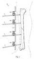
- FIG. 1is an illustration of an exemplary external fixation system in accordance with one exemplary aspect of the present disclosure connected to a patient's bone tissue.
- FIG. 2is an illustration of a clamping assembly of an external fixation system according to one exemplary aspect of the present disclosure.
- FIG. 3is an illustration of a clamp of the clamping assembly of FIG. 2 in an exploded view.
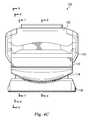
- FIGS. 4A-4Care illustrations of the clamp of FIG. 3 showing a side view, a top view, and a back view respectively.
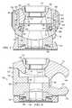
- FIG. 5is an illustration of a cross-section of the clamp of FIG. 4B taken through the lines 5 - 5 in FIG. 4B according to one exemplary aspect of the present disclosure.
- FIG. 6is an illustration of a cross-section of the clamp of FIG. 4C taken through the lines 6 - 6 in FIG. 4C according to one exemplary aspect of the present disclosure.
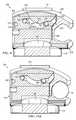
- FIG. 7is an illustration of a cross-section of the clamp of FIG. 4C taken through the lines 7 - 7 in FIG. 4C according to one exemplary aspect of the present disclosure.
- FIG. 8is an illustration of a cross-section of the clamp of FIG. 4C taken through the lines 8 - 8 in FIG. 4C according to one exemplary aspect of the present disclosure.
- FIG. 9is an illustration of a cross-section of the clamp of FIG. 4C taken through the lines 9 - 9 in FIG. 4C according to one exemplary aspect of the present disclosure.
- FIGS. 10A-10Care a series of illustrations of a cross-section of the clamp of FIG. 4C taken along the lines 9 - 9 , showing a cam slider in various positions as an upper jaw displaces relative to a lower jaw to capture or release a fixation element according to one exemplary aspect of the present disclosure.
- the present disclosureis directed to an external fixation system with a clamping assembly that employs a cam mechanism that opens a clamp of the clamping assembly to permit a health care provider to introduce a fixation element, such as a fixation rod or bar (or other fixation elements) and/or pin (or other fixation elements), between opposing jaws and into the clamp.
- the cam mechanismthen closes the clamp to capture the fixation element in a manner that prevents its removal from the clamp, unless cam sliders are actuated.
- the fixation elementis provisionally held in the clamp in a manner allowing the clamp to be axially displaced or slid along the fixation element or rotated about the fixation element, while preventing removal of the fixation element.
- the clampcan be fixed in place along the fixation element to prevent movement relative to the fixation element.
- the external fixation systemincludes a plurality of clamps arranged to receive and secure fixation elements that extend into or support patient tissue. These multiple clamps are arranged to pivot relative to each other about an axis coincident with a longitudinally extending post, and in some embodiments are also arranged to swivel relative to each other about an axis coincident with a transverse axle. This increases simplicity and efficiency of fixation system setup.
- FIG. 1shows an exemplary external fixation system 10 attached to a patient's fractured tibia.
- the system 10includes fixation elements as rigid bars 12 and pins 14 drilled into the bone on opposing sides of the fracture.
- fixation elementsas rigid bars 12 and pins 14 drilled into the bone on opposing sides of the fracture.
- this disclosurereferences bars and pins, it should be understood that any fixation element may be used, including bone pins, wires, rings, struts, bars, rods, or other structural members.
- each pin 14is received into one of the clamping devices 100 by inserting the pin 14 between facing jaws of a pin clamp of the clamping device 100 .
- the bar 12is received into each of the clamping devices 100 by inserting the bar 12 between facing jaws of a bar clamp of each clamping device 100 as is described further below, to establish the external fixation framework for bone stabilization.
- inserting the bar 12 or pin 14places the clamp in a provisionally locked condition. In this position, the respective clamp can be rotated about the bar 12 or pin 14 and may be axially displaced along the bar 12 or pin 14 .
- at least one of the clampsmay rotate about a longitudinal axis of the clamping device 100 , and may pitch up or down around the cylindrical axis of a saddle element, while the jaws maintain the bar or pin in the clamp.
- the clamping devicesmay be adjusted to provide angulation and orientation necessary to align the bone for healing. Additional bar-to-bar fixation clamps and/or bar-to-pin fixation clamps may be added to expand and connect the frame as required. Some embodiments include multipin clamps.
- FIGS. 2-9show an embodiment of the clamping device 100 .
- FIG. 2shows a side view of the clamping device and
- FIG. 3shows an exploded view of the clamping device.
- FIG. 2illustrates an exemplary clamping assembly 100 according to one exemplary aspect of the present disclosure.
- the clamping assembly 100includes a clamp 102 and an essentially identical clamp 104 that are structurally configured and arranged to clamp fixation elements.
- the clamps 102 and 104are essentially identical constructs conceptually and both may be considered bar clamps.
- other clamping assembliesmay employ pin clamps with the only significant differences involving dimensional changes to accommodate different fixation element diameters if required.
- only one of the clampsmay be used with alternative types of clamping constructs, including conventional single pin or bar clamping constructs, multi-bar or pin constructs, and other clamping systems. For example, in FIG.
- the clamping assembly 100may be formed of a first clamp dimensionally configured to capture and secure a fixation rod while the second clamp is dimensionally configured to capture and secure a bone pin.
- Each clamp 102 , 104independently receives and secures a bar, pin or other fixation element.
- Other embodiments of the clamping device 100include only a single bar or pin clamp on one end, with a multi-clamp set or other arrangement on the other end.
- the bar clamps 102 , 104 of the clamping assembly 100provide multiple degrees of freedom, each operating independently of the other.
- each clampmay pivot about a roll axis, a pitch axis, and a yaw axis in the clamp 102 , 104 .
- the roll axisis the axis of a bar or other fixation element within the clamps and about which the clamping device 100 may rotate.
- the pitch axisis a transverse axis about which the outer and inner jaws rotate relative to saddle components and/or the rest of the clamping assembly.
- the yaw axisis a longitudinal axis 107 defined by a post component or stud 108 and about which the clamp 102 can rotate relative to the clamp 104 .
- the clamping assembly 100is tightened onto a fixation element, and the clamp 102 is tightened to clamp 104 through tightening of a washer 112 , a nut 114 and the post component 108 (all in FIG. 2 ), although other tightening methods are contemplated.
- the post component 108includes a head (the top being visible in FIG. 2 ) and a shaft that extends through the clamping assembly to connect with the nut 106 .
- the head of the post component 108may be formed with a bowl-like surface shape, such as a spherical surface shape for example, that matches the spherical shape of the washer 112 , which can be seen in FIG. 3 .
- the post componentdoes not include a head, but has two threaded ends that cooperate with two nuts for tightening the clamping assembly 100 . Additional description of the axes and a post component or stud can be found in U.S. patent application Ser. No. 13/271,744 to Mullaney, filed Oct. 12, 2011, incorporated herein by reference.
- the clamping side of each clamp 102 , 104is intended to mean the side of the clamp that receives the fixation element and the rearward side is the side opposite the side of the clamp receiving the fixation element. In FIG. 2 , the clamping side of the clamp 102 is on the left and the clamping side of the clamp 104 is on the right.
- FIG. 2shows a side view of the clamping assembly 100 and FIG. 3 shows an exploded view of the clamp 102 .
- FIGS. 4A-4Crespectively show a side view, a top view, and a rear view.
- FIGS. 5-9are cross-sectional views taken through the respective lines 5 - 5 , 6 - 6 , 7 - 7 , 8 - 8 , and 9 - 9 in FIGS. 4B and 4C .
- the clamp 102includes an inner jaw 118 and an outer jaw 120 . These jaws cooperate to capture the fixation element therebetween.
- the clamp 102also includes a latch 122 , cam sliders 124 , guide pins 128 , sliding pins 130 , and stop pins 132 .
- the clamp 102also includes coil springs 134 , and balls 136 .
- the clampincludes a spacer 138 , a spring washer 140 , and a saddle 142 .
- Detailed descriptions of the spacer 138 , the spring washer 140 , and the saddle 142may be found in incorporated U.S. patent application Ser. No. 13/271,744, and therefore, they will not be described further here.
- the spacer 138 , the spring washer 140 , and the saddle 142are not required to be part of the clamp, but are in place to provide an extra degree of articulation for each of the clamps 102 and 104 .
- these componentsare not present in the clamping assembly 100 , and the inner jaw 118 of each of the clamps 102 , 104 is configured to bear against the opposing inner jaw directly, removing the extra degree of freedom.
- alternative pivoting elementsprovide the extra degree of freedom.
- each of the inner and outer jaws 118 , 120include respective grooves or concave recesses 146 , 148 for capturing the fixation element.
- the recesses 146 , 148may be shaped to generally correspond to the profile of the fixation elements, or may have shapes different than the profiles of the fixation elements.
- the recesses 146 , 148are configured to contact the fixation element at only particular locations, such as two locations each.
- the recessesinclude teeth, cut-outs, or other features that interface with bars having a non-smooth or non-circular outer surface.
- the jawsinclude flats on one or more of the jaws in place of the concave recesses.
- the inner jaw 118is configured and arranged with a base portion 152 and two extending wall portions 154 .
- the base portion 152includes a through hole 156 configured to receive the post component 108 , and in one embodiment, may allow the clamp 102 to pivot around the post component 108 . It may also be shaped to allow the clamp 102 to rotate or pivot relative to the post component 108 .
- the through hole 156may have a rectangular shape, with rounded ends as shown in FIG. 3 and may include a conical component as shown in the cross-sectional view of FIG. 5 . In other embodiments, the through hole 156 cooperates with the post component 108 to restrict relative rotation, while the clamp 104 and/or post component 108 is configured to permit relative rotation.
- the clamp 104may rotate about the post component relative to both the post component 108 and the clamp 102 in the manner described in incorporated U.S. patent application Ser. No. 13/271,744.
- the wall portions 154extend in substantially parallel planes from the base portion 152 , with each wall portion 154 including an inner surface 158 and an outer surface 160 .
- the inner surface 158includes a groove 162 extending along at least a portion of its length configured to receive a ball 136 , a coil spring 134 , and a stop pin 132 . This groove 162 is configured to cooperate with these elements to limit the movement of the latch 122 relative to the inner jaw 118 .
- Dove-tail grooves 163are formed in the outer surface 160 of the wall portions 154 . These transversely extending grooves are arranged to receive and connect with the cam sliders 124 in the manner discussed below.
- Each of the wall portions 154include guide slots 164 formed on the inner surface 158 .
- the angled slotsextend through the wall portions from the inner surface 158 to the outer surface 160 , and also extend into the drove tailed groove 163 .
- the guide slots 164are angled with one end of each slot at a lower elevation and the other end of each slot at a higher elevation. These guide slots 164 will guide the movement of the upper jaw as will become apparent from the discussion further below.
- the outer jaw 120is sized with a body portion 170 and a head portion 172 .
- the head portion 172includes the rod-receiving recess 148 .
- the body portion 170has a width sized to fit between the wall portions 154 in the inner jaw 118 , as can be seen in FIG. 5 . It includes a through hole 174 with a spherical top portion 176 and a rectangular, but conically shaped bottom portion 178 , that can be seen in FIG. 5 .
- the spherical top portion 176is arranged to cooperate and receive the spherical washer 112 .
- Four bore holes 180are formed into sides of the body portion 170 for receiving the guide pins 128 .
- a shoulder portion 182separates the head portion 172 and the body portion 170 . It projects out from the body portion 170 and may form a mechanical stop surface for the cam sliders 124 .
- the outer jaw 120also includes a back stop 184 adjacent the rod-receiving recess 148 . The back stop 184 cooperates with a fixation element as it is introduced into the clamp 102 , as will be explained below.
- the outer jaw 120is received into and held within the inner jaw 118 .
- the guide pins 128of which four are shown are pressed into the bore holes 180 through the guide slots 164 and act to retain the outer jaw 120 within the inner jaw 118 and effect movement of the outer jaw 120 relative to the inner jaw 118 as explained below. This can be seen in the cross-sectional view in FIG. 8 .
- the curvature of the guide slots 164 in the inner jaw 118is such that the center of rotation is generally about the same center as the spherical bore 166 formed in the outer jaw 120 although slight discrepancies from the center of rotation might be desirable in some embodiments.
- the guide pins 128travel along the guide slots 164 to effect movement of the upper jaw 120 relative to the lower jaw 118 .
- the width of the guide slots 164 in relationship to the diameter of the guide pins 128is determined based on the travel requirements of the outer jaw 120 relative to the inner jaw 118 to insure that adequate clamping force can be applied to the fixation element.
- these guide slots 164may have a width larger or smaller than that shown in order to permit the jaws 118 , 120 to suitably clamp onto a particularly sized fixation element, whether a bone pin, fixation rod or other fixation element.
- the latch 122extends into the inner jaw 118 and is configured to be disposed, at least in part, between the inner and outer jaws 118 , 120 . As will become apparent from the discussion below, the latch 122 moves forward and aft between the jaws 118 , 120 to wedge the outer jaw 120 into a closed position that secures a fixation element within the clamp 102 .
- the latch 122is formed in an L-shape, with a substantially horizontal portion 190 and a substantially vertical portion 192 .
- the substantially horizontal portion 190is bifurcated with two legs 194 formed by a central cut-out portion. The cut-out portion accommodates the post component 108 extending through the clamp 102 .
- Each of the legs 194includes a groove 196 extending along at least a portion of the legs 194 .
- the ball 136 , the coil spring 134 , and the stop pins 132are disposed in both the grooves 162 and the grooves 196 and cooperate to bias the latch 122 toward the receiving-half of the clamp 102 . That is, the coil spring 134 pushes the ball 136 toward the closed end of the groove 162 in the legs 194 . Likewise, the spring 134 pushes the stop pin 132 toward the closed end of the groove 162 . The net forces cooperate to bias the latch toward a location where the substantially vertical portion is between the inner and outer jaws 118 , 120 .
- the substantially vertical portion 192 of the latch 122is a blocking element having an upwardly facing surface 198 at the top of the latch 122 configured to interface with the inner surface of the upper jaw 120 and physically limit its ability to pivot around the spherical washer 112 , preventing displacement that would allow removal of a fixation element that will be contained between the inner and outer jaws 118 , 120 . This is shown in FIG. 6 . With the latch 122 disposed underneath the outer jaw 120 , the back end of the outer jaw 120 is mechanically prevented from rotating toward the inner jaw 118 .
- FIG. 6shows the clamp in a closed position. Since the ball 136 abuts the end of the groove 196 formed in the latch 122 , and since the stop pin 132 abuts an end of the corresponding groove 162 in the inner jaw 118 , the latch is biased toward this locked position. This can be seen in the cross-sectional view of FIG. 6 . Bores 200 are formed into sides of the substantially vertical portion 192 of the latch 122 . These bores 200 are configured to receive the stop pins 132 . These pins may be press fit with an interference that secures the stop pins 132 in the bores 200 , may be adhered with a cement or other adhesive, or may be otherwise formed or attached to the latch 122 .
- FIGS. 5-9corresponding to cross-sections 5 - 5 through 9 - 9 in FIGS. 4B and 4C , show the latch 122 in a fully engaged position wedging the outer jaw 120 into the closed position.
- the upwardly facing surface 198 of the latch 122is engaged with the lower surface of the outer jaw 120 at the rearward side of the clamp 102 .
- This positionis a provisional locking condition, with the inner and outer jaws 118 , 120 configured to prevent opening of the jaws and preventing removal or insertion of a fixation element between the jaws. To maintain this position, and as shown in FIG.
- the coil spring 134compresses ball 136 into the forward end of the groove 196 and bears against the stop pin 132 which bears against the end of the groove 162 ( FIG. 2 ) in the inner jaw 118 , acting to bias the latch 122 into the engaged position.
- the ball 136 and the cylinder stop pin 132are optional components that may provide for ease of manufacturing and to ensure an adequate bearing surface for the coil spring 134 .
- the cam sliders 124are disposed in and run along the wall portions 154 in the dovetail grooves 163 formed in the outer surface 160 of the wall portions 154 . This can be best seen in the cross-sectional view of FIG. 5 , but also shown in the exploded view of FIG. 3 .
- the cam sliders 124are independent of each other, and each has an outer facing surface 204 , an inner facing surface 206 that faces the wall portions 154 of the inner jaw 118 , a leading end 208 configured to match with and engage the shoulder portion 182 , and a trailing end 210 .
- the outer facing surface 196includes finger depressions formed therein for gripping by a user to slide the cam slider within the dove-tail groove 163 of the inner jaw wall portions 154 .
- the inner facing surface 198includes the dove-tailed feature 212 configured to match the dove-tailed groove 163 in the inner jaw 118 , includes a milled guide cam slot 214 formed in the dovetailed feature (best seen in FIGS. 3 and 9 ), includes a protruding stop portion 216 at the trailing end 202 , and includes a stop pin interface slot 218 formed in the protruding stop portion 216 .
- the stop pin interface slot 218is open at the trailing end 210 of the cam slider 124 and is disposed to receive and engage the stop pin 132 which is carried in the bore 200 on the latch 122 .
- the open end of the stop pin interface slot 218allows the cam sliders 124 to pull back and displace the latch 122 relative to the inner jaw 118 , but have no effect on the latch 122 when the cam sliders 124 are pushed forward. This decoupling of the cam sliders 124 from the latch 122 allows the latch 122 to operate independently when traversing from the open (unlatched) position to the closed (latched) position.
- the milled guide cam slot 214(labeled in FIG.
- the guide cam slot 214in this embodiment, includes an irregular surface having flat portions 224 and curved portions 226 .
- the guide cam slot 214along with the flat and curved portions, guide the movement of the upper jaw 120 relative to the inner jaw 118 to open and close the clamp 102 .
- two flat portions and two curved portionsare shown, other embodiments include only one flat portion while yet others include no flat portions. Additional flats or curves may be included to guide the movement of the upper jaw relative to the lower jaw to open and close the clamp 102 as will be described below.
- FIGS. 10A-10Cdepict an operational sequence of opening the clamp 102 to either capture or release a fixation element.
- the cross-sectionis taken through lines 9 - 9 in FIG. 4C .
- FIG. 10Ais similar to FIG. 9 , with the clamp 102 in a closed position, but includes a fixation element referenced by the numeral 12 .
- the cross-sectional view in FIGS. 10A-10C through one of the cam sliders 124shows the interaction between the guide cam slot 214 in the cam slider 124 , the guide slots 164 in the inner jaw 118 , and the guide pins 128 fixed on the upper jaw 120 to open and close the clamp 102 .
- FIG. 10Ashows the clamp in the closed position.
- FIG. 10Ashows the clamp in the closed position.
- FIG. 10Bshows the cam sliders 124 in a pulled back condition, thereby displacing the latch 122 from underneath the outer jaw 120 and beginning to move rearwardly such that the guide pins 128 are leaving the flat portion 224 of the milled guide slots 124 .
- the flat portion 224ensures that the outer jaw 120 can be locked in place.
- the guide pins 128are being forced into the curved portion 226 of the milled guide cam slot 214 effectively raising the front of the outer jaw 120 and effectively lowering the rear of the outer jaw 120 as it pivots about the spherical washer to open the clamp 102 .
- the cam slider 124is in a neutral position, with the stop pin 132 disposed in the flat or linear portion 224 of the guide cam slot 214 .
- the balls 136 , the coil springs 134 , and the sliding pins 130are disposed in the grooves 196 in the latch 122 and in the groove 162 in the inner jaw 118 .
- the biasing force from the spring 134acts against the ends of the groove 196 and the groove 162 to bias the latch 122 to a position where it physically interferes with and limits the rotational pivot range of the outer jaw 120 . This is the position shown in FIG.
- the clamp 102is in a provisionally locked state, where the clamp 102 cannot be opened to remove the fixation element 12 shown in FIG. 10A .
- the clamp 102may be loose enough on the fixation element 12 to permit spinning about the fixation element or sliding along the fixation element as the surgeon continues to construct the fixation frame or fixation system.
- the surgeon or health care providerIn order to open the clamp 102 , to either receive or remove the fixation element, the surgeon or health care provider must displace the cam sliders 124 rearwardly relative to the inner and outer jaws 118 , 120 . Accordingly, the surgeon may grip the cam sliders 124 along their gripping portions on the outer facing surfaces 204 using a thumb and fingers, and move the cam sliders 124 rearwardly, away from the clamping side of the clamp 102 . Rearward displacement of the cam sliders 124 causes the milled stop pin interface slots 218 in the cam sliders 124 to apply a displacement force on the stop pins 132 that are fixed into the latch 122 , forcing the latch 122 to move rearwardly with the cam sliders 124 .
- the slots 164 in the inner jaw 118 and the cam slots 214 in the cam slider 124are sized and arranged to open the jaws of the clamp 102 a particular distance, to receive a particularly sized fixation element. Accordingly, certain clamp embodiments will be arranged to receive the bone pins 14 in FIG. 1 , while other clamp embodiments will be arranged to receive the external fixation rods 12 .
- the shapescan be formed to fit any size of fixation element.
- the clamp 102With the clamp 102 in the open position shown in FIG. 10C , the clamp is ready to receive the fixation element. In this position, even if the operator releases the cam slider 124 , the clamp 102 is maintained in the open position. This is because the outer jaw 120 has pivoted about the spherical washer 112 so that the rearward side of the jaw 120 is below the uppermost upwardly facing surface 196 of the latch 122 . With the latch 122 still biased toward to the open end of the clamp 102 , the substantially vertical portion is behind the outer jaw, rather than between the outer and inner jaws 120 , 118 .
- the latch's forward movementis physically blocked by the location of the rearward end of the outer jaw 120 .
- the biased latchcannot move further between the jaws 118 , 120 . Accordingly, in this position, the latch is effectively cocked and the clamp is ready to snap onto a fixation element.
- the fixation elementWhen the fixation element is introduced between the open jaws, it may be placed within the passage between the open jaws.
- the fixation elementcomes into contact with the backstop 184 on the outer jaw 120 and further advancement causes the outer jaw 120 to pivot about the spherical washer, with the front end of the jaw moving toward the inner jaw 118 and the rearward end of the jaw moving away from the inner jaw 118 .
- the latchadvances due to the biasing force of the springs 134 to the position shown in FIG. 7 .
- the stop pins 132 in the bores 200 on the latchengage the stop pin interface slots 218 on the cam sliders 124 and likewise advance the cam sliders 124 with the advancing latch 122 .
- the clamp 102is in the provisionally locked state and the fixation element cannot be removed from the clamp 102 . Accordingly, the fixation element is captured in the manner shown in FIG. 10A .
- the clamping assembly 100can be rigidly locked on the fixation element 12 by applying a clamping load with the inner and outer jaws 118 , 120 onto the fixation element 12 .
- the stud or post component 108 and the nut 106cooperate to pass entirely through the clamping assembly 100 . Tightening the nut 106 lessens the distance between the nut 106 and the head of the post component 108 shown in FIG. 2 . This lessening of that distance forces the spherical washer 112 against the outer jaw 120 which in turn forces the outer jaw 120 closer to the inner jaw 118 , tightening the construct on the fixation element.
- the guide slots 164are formed and shaped to permit this downward displacement of the outer jaw 120 relative to the inner jaw 118 . Because the rearward portion of the outer jaw 120 cannot displace further toward the inner jaw 118 because of the latch 122 , the displacement occurs primarily at the clamping side, increasing the clamping load on the fixation element 12 in the receiving-recesses 146 , 148 . In addition, the spring washer 140 opposes this displacement. The tightening causes the spring washer 140 to compress, locking the inner jaw 118 into serrations on the saddle 142 , and locking serrations on the saddles of the opposing clamps 102 , 104 to each other.
- the spring rateis tailored to allow for a variable amount of friction as a function of nut torque such that the resistance to motion of the fixation element 12 can be adjusted to facilitate gross manipulation of the jaws 118 , 120 relative to the saddle 142 and the saddles 142 of each clamp 102 , 104 relative to each other without such a high degree of force being applied such that the serrations on the saddle 142 become engaged with the opposing serrations on the inner jaws 118 .
- a high rate spring washer 140may be used between the saddle 142 and its mating inner jaw 118 . Accordingly, positively clamping on the fixation element 12 forces the spring washer 140 to collapse, thereby allowing the serrations on opposing saddles 142 and on the inner jaws 118 to come into engagement positively locking the construct in a fixed state.
- the guided cam actionboth increases and decreases the size of the bar-receiving opening. Accordingly, the clamp does not rely upon a longitudinal spring pressure or biasing force to open and close the jaws or to place the jaws in a provisionally locked state from an open state. Instead, the jaws are guided into the open position and the provisionally locked position via the guide slots that act as a track that guides and directs the movement of the jaws relative to each other.
Landscapes
- Health & Medical Sciences (AREA)
- Orthopedic Medicine & Surgery (AREA)
- Life Sciences & Earth Sciences (AREA)
- Surgery (AREA)
- Biomedical Technology (AREA)
- Engineering & Computer Science (AREA)
- Nuclear Medicine, Radiotherapy & Molecular Imaging (AREA)
- Heart & Thoracic Surgery (AREA)
- Medical Informatics (AREA)
- Molecular Biology (AREA)
- Animal Behavior & Ethology (AREA)
- General Health & Medical Sciences (AREA)
- Public Health (AREA)
- Veterinary Medicine (AREA)
- Surgical Instruments (AREA)
Abstract
Description
Claims (27)
Priority Applications (1)
| Application Number | Priority Date | Filing Date | Title |
|---|---|---|---|
| US13/315,535US9149296B2 (en) | 2010-12-09 | 2011-12-09 | Cam driven jaw for external fixation clamps |
Applications Claiming Priority (2)
| Application Number | Priority Date | Filing Date | Title |
|---|---|---|---|
| US42149210P | 2010-12-09 | 2010-12-09 | |
| US13/315,535US9149296B2 (en) | 2010-12-09 | 2011-12-09 | Cam driven jaw for external fixation clamps |
Publications (2)
| Publication Number | Publication Date |
|---|---|
| US20120150184A1 US20120150184A1 (en) | 2012-06-14 |
| US9149296B2true US9149296B2 (en) | 2015-10-06 |
Family
ID=45401173
Family Applications (1)
| Application Number | Title | Priority Date | Filing Date |
|---|---|---|---|
| US13/315,535Active2033-10-27US9149296B2 (en) | 2010-12-09 | 2011-12-09 | Cam driven jaw for external fixation clamps |
Country Status (3)
| Country | Link |
|---|---|
| US (1) | US9149296B2 (en) |
| EP (1) | EP2648633B1 (en) |
| WO (1) | WO2012078893A1 (en) |
Families Citing this family (8)
| Publication number | Priority date | Publication date | Assignee | Title |
|---|---|---|---|---|
| IT1396145B1 (en)* | 2009-11-05 | 2012-11-16 | Citieffe Srl | MULTI-PURPOSE EXTERNAL FIXER. |
| EP2648633B1 (en) | 2010-12-09 | 2016-05-18 | Zimmer, Inc. | External fixation clamp with cam driven jaw |
| JP6106662B2 (en)* | 2011-05-17 | 2017-04-05 | ジンマー,インコーポレイティド | External fixed clamping system using a starting mechanism and stored spring energy |
| US9155561B2 (en) | 2013-03-06 | 2015-10-13 | Stryker Trauma Sa | Mini-rail external fixator |
| ITMI20130407A1 (en)* | 2013-03-18 | 2014-09-19 | Orthofix Srl | EXTERNAL FIXING DEVICE |
| US9962188B2 (en) | 2013-10-29 | 2018-05-08 | Cardinal Health 247. Inc. | External fixation system and methods of use |
| US10531896B2 (en) | 2015-08-10 | 2020-01-14 | Stryker European Holdings I, Llc | Distraction tube with wire clamp |
| US11737786B2 (en) | 2019-12-31 | 2023-08-29 | Orthopediatrics Corp. | Multiple track system for positioning of bone segments |
Citations (92)
| Publication number | Priority date | Publication date | Assignee | Title |
|---|---|---|---|---|
| US1706215A (en) | 1926-01-26 | 1929-03-19 | American Safety Device Co | Adjustable coupling means |
| US2705603A (en) | 1953-06-09 | 1955-04-05 | John O Bitz | Antenna pole clamp |
| US3044512A (en) | 1960-05-31 | 1962-07-17 | Monogram Prec Ind Inc | Clamp |
| US3154331A (en) | 1960-04-25 | 1964-10-27 | Armin E Engelhardt | Shaft clamping devices |
| US3373465A (en)* | 1966-03-24 | 1968-03-19 | Up Right Inc | Locking hook with arcuately slidable locking member |
| US3406987A (en) | 1965-04-26 | 1968-10-22 | Minnesota Mining & Mfg | Split-sleeve sheet metal pipe coupling |
| DE2430234A1 (en) | 1973-06-26 | 1975-01-16 | Glatz Ag | Connection for two crossing tubes - has screw tightening and serrated face location at angular increments for use on sun shields |
| US4037978A (en) | 1974-08-23 | 1977-07-26 | B.C. Investments Ltd. | Resilient swivel connector |
| US4115966A (en) | 1977-02-14 | 1978-09-26 | Delee Barry | Clamping device for display structures |
| US4312488A (en) | 1978-07-08 | 1982-01-26 | A. Raymond | Clamp for securing articles of round cross section |
| US4388747A (en) | 1981-08-10 | 1983-06-21 | Plummer Walter A | One-piece molded toggle clamp |
| US4483334A (en) | 1983-04-11 | 1984-11-20 | Murray William M | External fixation device |
| US4620533A (en) | 1985-09-16 | 1986-11-04 | Pfizer Hospital Products Group Inc. | External bone fixation apparatus |
| US4653481A (en) | 1985-07-24 | 1987-03-31 | Howland Robert S | Advanced spine fixation system and method |
| US4662365A (en) | 1982-12-03 | 1987-05-05 | Ortopedia Gmbh | Device for the external fixation of bone fragments |
| US4700437A (en) | 1986-07-23 | 1987-10-20 | Hoshino Gakki Co., Ltd. | Lever lock clamp |
| USD295725S (en) | 1985-12-06 | 1988-05-17 | Nifco Inc. | Retainer clamp for elongated bodies or the like |
| US4817897A (en) | 1986-02-12 | 1989-04-04 | Ulrich Kreusel | Cross-connector to two crossing tubular elements |
| WO1989005126A1 (en) | 1987-11-19 | 1989-06-15 | Harrington Arthritis Research Center | Unilateral external fixation device |
| WO1990011055A1 (en) | 1989-03-14 | 1990-10-04 | Tatar Peter | External fixation |
| WO1992012683A1 (en) | 1991-01-15 | 1992-08-06 | Confida S.A.S. | Single-use locking fastener device and bone support device |
| US5312405A (en) | 1992-07-06 | 1994-05-17 | Zimmer, Inc. | Spinal rod coupler |
| US5427465A (en) | 1992-09-25 | 1995-06-27 | Sato; Masataro | Clamp fitment for connecting pipe sections |
| US5662648A (en) | 1993-03-15 | 1997-09-02 | Orthofix S.R.L. | Method and apparatus for the external setting of fractures |
| US5683389A (en) | 1994-12-05 | 1997-11-04 | Smith & Nephew, Inc. | External fixator for distal radius fractures |
| US5709681A (en) | 1995-09-19 | 1998-01-20 | Pennig; Dietmar | Device for osteosynthesis |
| US5727899A (en) | 1996-09-13 | 1998-03-17 | Minnesota Scientific, Inc. | Fulcrum clamp |
| US5741252A (en) | 1996-03-25 | 1998-04-21 | Synthes U.S.A. | Adjustable clamp for bone fixation element |
| US5746741A (en) | 1996-05-06 | 1998-05-05 | Tufts University | External fixator system |
| US5752954A (en) | 1994-09-06 | 1998-05-19 | Howmedica International | External fixation device |
| US5800548A (en) | 1996-03-05 | 1998-09-01 | Bruno Franck | Device for transverse spinal connection |
| US5827282A (en) | 1991-07-12 | 1998-10-27 | Orthofix S.R.1. | Clamping coupling |
| WO1998051227A1 (en) | 1997-05-15 | 1998-11-19 | Wright Medical Technology, Inc. | External fixation system |
| US5860728A (en) | 1993-02-08 | 1999-01-19 | Mag Instrument, Inc. | Holder clamp assembly |
| US5891144A (en) | 1996-05-10 | 1999-04-06 | Jaquet Orthopedie S.A. | External fixator |
| WO1999025264A1 (en) | 1997-11-18 | 1999-05-27 | Electro-Biology, Inc. | Method and apparatus for external fixation of bones |
| US5976141A (en) | 1995-02-23 | 1999-11-02 | Synthes (U.S.A.) | Threaded insert for bone plate screw hole |
| US6022348A (en) | 1997-11-30 | 2000-02-08 | Spitzer; Daniel | Clamping connection for medical equipment and apparatus |
| US6102911A (en) | 1997-02-13 | 2000-08-15 | Orthofix S.R.L. | Orthopaedic apparatus, particularly for the surgical correction of bone deformities |
| US6217577B1 (en) | 1999-01-21 | 2001-04-17 | Medicalplastic S.R.L. | Outer fixing device for orthopedics and traumatology |
| US20010004432A1 (en) | 1999-03-26 | 2001-06-21 | Pfister Joel W. | Attachment system for configured slots |
| US6277069B1 (en) | 1998-06-09 | 2001-08-21 | Pine Ridge Holding Pty. Ltd. | Clamping device |
| US20020037193A1 (en) | 2000-09-27 | 2002-03-28 | Alan Dick & Company Limited | Cable clamp |
| US20020042613A1 (en) | 1998-12-29 | 2002-04-11 | Jacques Mata | Positioning and locking device |
| US6376775B1 (en) | 1996-05-29 | 2002-04-23 | Abb Ab | Conductor for high-voltage windings and a rotating electric machine comprising a winding including the conductor |
| US6386786B1 (en) | 2000-04-07 | 2002-05-14 | Delaware Capital Formation, Inc. | Rotating clamp |
| US20020061225A1 (en) | 2000-03-28 | 2002-05-23 | Boucher Michael M. | Socket and rail clamp apparatus |
| US6409729B1 (en) | 1998-05-19 | 2002-06-25 | Synthes (Usa) | Clamp assembly for an external fixation system |
| US20020165543A1 (en) | 2000-02-02 | 2002-11-07 | Winquist Robert A. | Adjustable bone stabilizing frame system |
| US6500177B1 (en) | 1998-05-19 | 2002-12-31 | Synthes (Usa) | Telescopic body for an external fixation system |
| US20030149429A1 (en) | 2002-02-04 | 2003-08-07 | Joseph Ferrante | External fixation system |
| WO2003065911A1 (en) | 2002-02-04 | 2003-08-14 | Smith & Nephew, Inc. | External fixation system |
| US20030191370A1 (en)* | 2002-04-05 | 2003-10-09 | Phillips Burns P. | Side loading surgical retractor |
| US6637082B1 (en) | 2002-09-27 | 2003-10-28 | Chun-Yuan Chang | Quick holder |
| US6652523B1 (en) | 1998-12-29 | 2003-11-25 | Delegation General Pour L'armement | Monolateral orthopedic device with external fixing for immobilizing a fractured bone |
| US6702814B2 (en) | 1999-10-21 | 2004-03-09 | Ebi, L.P. | Clamp assembly for an external fixation system |
| US6716212B1 (en) | 2002-01-25 | 2004-04-06 | Tyrone Sam Pickens | Universal modular external fixation system |
| US6736775B2 (en) | 2001-05-23 | 2004-05-18 | Boss Instruments Limited | Retractor clamp assembly |
| US6887197B2 (en) | 2001-10-05 | 2005-05-03 | Boss Instruments Ltd. | Side loading surgical retractor having offset cavity |
| US20050113831A1 (en) | 2002-02-11 | 2005-05-26 | Bruno Franck | Connection system between a spinal rod and a transverse bar |
| US20060017566A1 (en) | 2004-06-10 | 2006-01-26 | Jean-Louis Gauvreau | RF volumetric intrusion detection device, system and method |
| US20060039750A1 (en) | 2004-08-20 | 2006-02-23 | Stryker Trauma S.A. | Clamping and articulation element |
| US7097616B2 (en)* | 2003-10-08 | 2006-08-29 | Minnesota Scientific, Inc. | Surgical clamp |
| US20060229602A1 (en) | 2005-03-18 | 2006-10-12 | Olsen Ron A | Adjustable splint for osteosynthesis |
| US20060255521A1 (en) | 2003-06-26 | 2006-11-16 | Peter Brunner | Clamp for external fixation |
| US20060271045A1 (en) | 2005-05-27 | 2006-11-30 | Depuy Spine, Inc. | Spinal cross-connector |
| US20060287652A1 (en) | 2005-06-21 | 2006-12-21 | Lessig Richard K | Adjustable fixation clamp and method |
| US20070038217A1 (en) | 2005-08-09 | 2007-02-15 | Brown Daniel G | Orthopaedic fixation clamp and method |
| US20070049932A1 (en) | 2005-08-23 | 2007-03-01 | Aesculap Ag & Co. Kg | Rod to rod connector |
| US7241071B2 (en) | 2004-03-08 | 2007-07-10 | Jiffy Clip, Inc. | Swiveling multi-clamp fastener |
| EP1820461A1 (en) | 2006-02-21 | 2007-08-22 | Stryker Trauma SA | Clamping and articulation element |
| US7261713B2 (en) | 2001-10-09 | 2007-08-28 | Synthes (Usa) | Adjustable fixator |
| US20070293860A1 (en) | 2004-04-19 | 2007-12-20 | Marc Oesch | Elastic Element Produced From Radiolucent Material For A Medical Device |
| US7314331B1 (en) | 2004-08-11 | 2008-01-01 | Tibor Koros | Multi-position locking mechanisms for clamping assemblies |
| US7320556B2 (en) | 2000-07-11 | 2008-01-22 | Dall Vagn-Erik | Gripping devices |
| US20080065068A1 (en) | 2004-11-30 | 2008-03-13 | Roland Thomke | Insert for a Clamping Element, Clamping Element Comprising Said Insert and Universal Joint Produced Therefrom |
| US20080215053A1 (en) | 2006-10-13 | 2008-09-04 | Stryker Trauma Sa | Prevention of re-use of a medical device |
| US7473223B2 (en) | 2005-02-07 | 2009-01-06 | Peter Edward Fetzer | Push-button activated grasper for surgical retractor |
| WO2009004347A1 (en) | 2007-07-03 | 2009-01-08 | Raffan, Peter | Pin clamp |
| US7491008B2 (en) | 2005-02-09 | 2009-02-17 | Stryker Trauma S.A. | External fixation clamp |
| US20090088751A1 (en)* | 2007-09-27 | 2009-04-02 | Qfx Technologies, Incorporated | Method and Clamping Apparatus for External Fixation and Stabilization |
| US7527626B2 (en) | 2003-10-06 | 2009-05-05 | Stryker Trauma Sa | External fixation element |
| US7562855B2 (en) | 2004-12-15 | 2009-07-21 | Blanking Systems, Inc. | Clamping mechanism for folder gluer machine |
| US7588537B2 (en) | 2005-09-07 | 2009-09-15 | West Coast Surgical, Llc. | Connector with safety latch for a surgical retractor |
| US20090299368A1 (en) | 2005-04-01 | 2009-12-03 | Tantum Ag | Fixation Device for Stably Interlinking At Least Two Bone Fragments of a Broken Bone and Corresponding Fixation Element and Kit |
| US7708736B2 (en) | 2006-02-22 | 2010-05-04 | Extraortho, Inc. | Articulation apparatus for external fixation device |
| US7744632B2 (en) | 2006-12-20 | 2010-06-29 | Aesculap Implant Systems, Inc. | Rod to rod connector |
| EP2294994A1 (en) | 2009-09-11 | 2011-03-16 | Stryker Trauma SA | External fixation component |
| US20120004659A1 (en) | 2010-07-01 | 2012-01-05 | Extraortho, Inc. | Multi-Locking External Fixation Clamp |
| US20120089142A1 (en) | 2010-10-12 | 2012-04-12 | Extraortho, Inc. | Single Lock External Fixation Clamp Arrangement and Method |
| US20120095462A1 (en) | 2010-10-12 | 2012-04-19 | Extraortho, Inc. | External Fixation Surgical Clamp with Swivel |
| WO2012078893A1 (en) | 2010-12-09 | 2012-06-14 | Extraortho, Inc. | External fixation clamp with cam driven jaw |
- 2011
- 2011-12-08EPEP11799922.7Apatent/EP2648633B1/enactiveActive
- 2011-12-08WOPCT/US2011/063976patent/WO2012078893A1/enactiveApplication Filing
- 2011-12-09USUS13/315,535patent/US9149296B2/enactiveActive
Patent Citations (106)
| Publication number | Priority date | Publication date | Assignee | Title |
|---|---|---|---|---|
| US1706215A (en) | 1926-01-26 | 1929-03-19 | American Safety Device Co | Adjustable coupling means |
| US2705603A (en) | 1953-06-09 | 1955-04-05 | John O Bitz | Antenna pole clamp |
| US3154331A (en) | 1960-04-25 | 1964-10-27 | Armin E Engelhardt | Shaft clamping devices |
| US3044512A (en) | 1960-05-31 | 1962-07-17 | Monogram Prec Ind Inc | Clamp |
| US3406987A (en) | 1965-04-26 | 1968-10-22 | Minnesota Mining & Mfg | Split-sleeve sheet metal pipe coupling |
| US3373465A (en)* | 1966-03-24 | 1968-03-19 | Up Right Inc | Locking hook with arcuately slidable locking member |
| DE2430234A1 (en) | 1973-06-26 | 1975-01-16 | Glatz Ag | Connection for two crossing tubes - has screw tightening and serrated face location at angular increments for use on sun shields |
| US4037978A (en) | 1974-08-23 | 1977-07-26 | B.C. Investments Ltd. | Resilient swivel connector |
| US4115966A (en) | 1977-02-14 | 1978-09-26 | Delee Barry | Clamping device for display structures |
| US4312488A (en) | 1978-07-08 | 1982-01-26 | A. Raymond | Clamp for securing articles of round cross section |
| US4388747A (en) | 1981-08-10 | 1983-06-21 | Plummer Walter A | One-piece molded toggle clamp |
| US4662365A (en) | 1982-12-03 | 1987-05-05 | Ortopedia Gmbh | Device for the external fixation of bone fragments |
| US4483334A (en) | 1983-04-11 | 1984-11-20 | Murray William M | External fixation device |
| US4653481A (en) | 1985-07-24 | 1987-03-31 | Howland Robert S | Advanced spine fixation system and method |
| US4620533A (en) | 1985-09-16 | 1986-11-04 | Pfizer Hospital Products Group Inc. | External bone fixation apparatus |
| USD295725S (en) | 1985-12-06 | 1988-05-17 | Nifco Inc. | Retainer clamp for elongated bodies or the like |
| US4817897A (en) | 1986-02-12 | 1989-04-04 | Ulrich Kreusel | Cross-connector to two crossing tubular elements |
| US4700437A (en) | 1986-07-23 | 1987-10-20 | Hoshino Gakki Co., Ltd. | Lever lock clamp |
| WO1989005126A1 (en) | 1987-11-19 | 1989-06-15 | Harrington Arthritis Research Center | Unilateral external fixation device |
| WO1990011055A1 (en) | 1989-03-14 | 1990-10-04 | Tatar Peter | External fixation |
| WO1992012683A1 (en) | 1991-01-15 | 1992-08-06 | Confida S.A.S. | Single-use locking fastener device and bone support device |
| US5827282A (en) | 1991-07-12 | 1998-10-27 | Orthofix S.R.1. | Clamping coupling |
| US5312405A (en) | 1992-07-06 | 1994-05-17 | Zimmer, Inc. | Spinal rod coupler |
| US5427465A (en) | 1992-09-25 | 1995-06-27 | Sato; Masataro | Clamp fitment for connecting pipe sections |
| US5860728A (en) | 1993-02-08 | 1999-01-19 | Mag Instrument, Inc. | Holder clamp assembly |
| US5662648A (en) | 1993-03-15 | 1997-09-02 | Orthofix S.R.L. | Method and apparatus for the external setting of fractures |
| US5752954A (en) | 1994-09-06 | 1998-05-19 | Howmedica International | External fixation device |
| US6080153A (en) | 1994-09-06 | 2000-06-27 | Howmedica International | External fixation device |
| US5683389A (en) | 1994-12-05 | 1997-11-04 | Smith & Nephew, Inc. | External fixator for distal radius fractures |
| US5976141A (en) | 1995-02-23 | 1999-11-02 | Synthes (U.S.A.) | Threaded insert for bone plate screw hole |
| US5709681A (en) | 1995-09-19 | 1998-01-20 | Pennig; Dietmar | Device for osteosynthesis |
| US5800548A (en) | 1996-03-05 | 1998-09-01 | Bruno Franck | Device for transverse spinal connection |
| US5741252A (en) | 1996-03-25 | 1998-04-21 | Synthes U.S.A. | Adjustable clamp for bone fixation element |
| US5746741A (en) | 1996-05-06 | 1998-05-05 | Tufts University | External fixator system |
| US5891144A (en) | 1996-05-10 | 1999-04-06 | Jaquet Orthopedie S.A. | External fixator |
| US6376775B1 (en) | 1996-05-29 | 2002-04-23 | Abb Ab | Conductor for high-voltage windings and a rotating electric machine comprising a winding including the conductor |
| US5727899A (en) | 1996-09-13 | 1998-03-17 | Minnesota Scientific, Inc. | Fulcrum clamp |
| US6102911A (en) | 1997-02-13 | 2000-08-15 | Orthofix S.R.L. | Orthopaedic apparatus, particularly for the surgical correction of bone deformities |
| WO1998051227A1 (en) | 1997-05-15 | 1998-11-19 | Wright Medical Technology, Inc. | External fixation system |
| WO1999025264A1 (en) | 1997-11-18 | 1999-05-27 | Electro-Biology, Inc. | Method and apparatus for external fixation of bones |
| US6022348A (en) | 1997-11-30 | 2000-02-08 | Spitzer; Daniel | Clamping connection for medical equipment and apparatus |
| US6500177B1 (en) | 1998-05-19 | 2002-12-31 | Synthes (Usa) | Telescopic body for an external fixation system |
| US6409729B1 (en) | 1998-05-19 | 2002-06-25 | Synthes (Usa) | Clamp assembly for an external fixation system |
| US6277069B1 (en) | 1998-06-09 | 2001-08-21 | Pine Ridge Holding Pty. Ltd. | Clamping device |
| US20020042613A1 (en) | 1998-12-29 | 2002-04-11 | Jacques Mata | Positioning and locking device |
| US6652523B1 (en) | 1998-12-29 | 2003-11-25 | Delegation General Pour L'armement | Monolateral orthopedic device with external fixing for immobilizing a fractured bone |
| US6217577B1 (en) | 1999-01-21 | 2001-04-17 | Medicalplastic S.R.L. | Outer fixing device for orthopedics and traumatology |
| US20010004432A1 (en) | 1999-03-26 | 2001-06-21 | Pfister Joel W. | Attachment system for configured slots |
| US6702814B2 (en) | 1999-10-21 | 2004-03-09 | Ebi, L.P. | Clamp assembly for an external fixation system |
| US20020165543A1 (en) | 2000-02-02 | 2002-11-07 | Winquist Robert A. | Adjustable bone stabilizing frame system |
| US20040044344A1 (en)* | 2000-02-02 | 2004-03-04 | Winquist Robert A. | Adjustable bone stabilizing frame system |
| US20020061225A1 (en) | 2000-03-28 | 2002-05-23 | Boucher Michael M. | Socket and rail clamp apparatus |
| US6386786B1 (en) | 2000-04-07 | 2002-05-14 | Delaware Capital Formation, Inc. | Rotating clamp |
| US7320556B2 (en) | 2000-07-11 | 2008-01-22 | Dall Vagn-Erik | Gripping devices |
| US20020037193A1 (en) | 2000-09-27 | 2002-03-28 | Alan Dick & Company Limited | Cable clamp |
| US6736775B2 (en) | 2001-05-23 | 2004-05-18 | Boss Instruments Limited | Retractor clamp assembly |
| US6887197B2 (en) | 2001-10-05 | 2005-05-03 | Boss Instruments Ltd. | Side loading surgical retractor having offset cavity |
| US7261713B2 (en) | 2001-10-09 | 2007-08-28 | Synthes (Usa) | Adjustable fixator |
| US6716212B1 (en) | 2002-01-25 | 2004-04-06 | Tyrone Sam Pickens | Universal modular external fixation system |
| WO2003065911A1 (en) | 2002-02-04 | 2003-08-14 | Smith & Nephew, Inc. | External fixation system |
| US7887537B2 (en)* | 2002-02-04 | 2011-02-15 | Smith & Nephew, Inc. | External fixation system |
| US20050119656A1 (en)* | 2002-02-04 | 2005-06-02 | Joseph Ferrante | External fixation system |
| US20030149429A1 (en) | 2002-02-04 | 2003-08-07 | Joseph Ferrante | External fixation system |
| US7004943B2 (en) | 2002-02-04 | 2006-02-28 | Smith & Nephew, Inc. | Devices, systems, and methods for placing and positioning fixation elements in external fixation systems |
| US7048735B2 (en) | 2002-02-04 | 2006-05-23 | Smith & Nephew | External fixation system |
| US20050113831A1 (en) | 2002-02-11 | 2005-05-26 | Bruno Franck | Connection system between a spinal rod and a transverse bar |
| US20030191370A1 (en)* | 2002-04-05 | 2003-10-09 | Phillips Burns P. | Side loading surgical retractor |
| US6637082B1 (en) | 2002-09-27 | 2003-10-28 | Chun-Yuan Chang | Quick holder |
| US20060255521A1 (en) | 2003-06-26 | 2006-11-16 | Peter Brunner | Clamp for external fixation |
| US7527626B2 (en) | 2003-10-06 | 2009-05-05 | Stryker Trauma Sa | External fixation element |
| US7097616B2 (en)* | 2003-10-08 | 2006-08-29 | Minnesota Scientific, Inc. | Surgical clamp |
| US7241071B2 (en) | 2004-03-08 | 2007-07-10 | Jiffy Clip, Inc. | Swiveling multi-clamp fastener |
| US20070293860A1 (en) | 2004-04-19 | 2007-12-20 | Marc Oesch | Elastic Element Produced From Radiolucent Material For A Medical Device |
| US20060017566A1 (en) | 2004-06-10 | 2006-01-26 | Jean-Louis Gauvreau | RF volumetric intrusion detection device, system and method |
| US7314331B1 (en) | 2004-08-11 | 2008-01-01 | Tibor Koros | Multi-position locking mechanisms for clamping assemblies |
| US7241074B2 (en) | 2004-08-20 | 2007-07-10 | Stryker Trauma S.A. | Clamping and articulation element |
| US20060039750A1 (en) | 2004-08-20 | 2006-02-23 | Stryker Trauma S.A. | Clamping and articulation element |
| US20080065068A1 (en) | 2004-11-30 | 2008-03-13 | Roland Thomke | Insert for a Clamping Element, Clamping Element Comprising Said Insert and Universal Joint Produced Therefrom |
| US7562855B2 (en) | 2004-12-15 | 2009-07-21 | Blanking Systems, Inc. | Clamping mechanism for folder gluer machine |
| US7473223B2 (en) | 2005-02-07 | 2009-01-06 | Peter Edward Fetzer | Push-button activated grasper for surgical retractor |
| US7491008B2 (en) | 2005-02-09 | 2009-02-17 | Stryker Trauma S.A. | External fixation clamp |
| US20060229603A1 (en) | 2005-03-18 | 2006-10-12 | Olsen Ron A | Adjustable splint for osteosynthesis with modular joint |
| US20060229602A1 (en) | 2005-03-18 | 2006-10-12 | Olsen Ron A | Adjustable splint for osteosynthesis |
| US20090299368A1 (en) | 2005-04-01 | 2009-12-03 | Tantum Ag | Fixation Device for Stably Interlinking At Least Two Bone Fragments of a Broken Bone and Corresponding Fixation Element and Kit |
| US20060271045A1 (en) | 2005-05-27 | 2006-11-30 | Depuy Spine, Inc. | Spinal cross-connector |
| US20060287652A1 (en) | 2005-06-21 | 2006-12-21 | Lessig Richard K | Adjustable fixation clamp and method |
| US20090036891A1 (en) | 2005-08-09 | 2009-02-05 | Zimmer Technology, Inc. | Orthopaedic fixation clamp and method |
| US20070038217A1 (en) | 2005-08-09 | 2007-02-15 | Brown Daniel G | Orthopaedic fixation clamp and method |
| US20070049932A1 (en) | 2005-08-23 | 2007-03-01 | Aesculap Ag & Co. Kg | Rod to rod connector |
| US7588537B2 (en) | 2005-09-07 | 2009-09-15 | West Coast Surgical, Llc. | Connector with safety latch for a surgical retractor |
| EP1820461A1 (en) | 2006-02-21 | 2007-08-22 | Stryker Trauma SA | Clamping and articulation element |
| US20070198012A1 (en) | 2006-02-21 | 2007-08-23 | Stryker Trauma Sa | Clamping and articulation element |
| US7938829B2 (en)* | 2006-02-22 | 2011-05-10 | Extraortho, Inc. | Articulation apparatus for external fixation device |
| US7708736B2 (en) | 2006-02-22 | 2010-05-04 | Extraortho, Inc. | Articulation apparatus for external fixation device |
| US20110172663A1 (en) | 2006-02-22 | 2011-07-14 | Extraortho, Inc. | Articulation apparatus for external fixation device |
| US20080215053A1 (en) | 2006-10-13 | 2008-09-04 | Stryker Trauma Sa | Prevention of re-use of a medical device |
| US7744632B2 (en) | 2006-12-20 | 2010-06-29 | Aesculap Implant Systems, Inc. | Rod to rod connector |
| WO2009004347A1 (en) | 2007-07-03 | 2009-01-08 | Raffan, Peter | Pin clamp |
| US20090088751A1 (en)* | 2007-09-27 | 2009-04-02 | Qfx Technologies, Incorporated | Method and Clamping Apparatus for External Fixation and Stabilization |
| US20110098707A1 (en) | 2007-09-27 | 2011-04-28 | Extraortho, Inc. | Method and clamping apparatus for external fixation and stabilization |
| US20110098706A1 (en) | 2007-09-27 | 2011-04-28 | Mullaney Michael W | Method and clamping apparatus for external fixation and stabilization |
| EP2294994A1 (en) | 2009-09-11 | 2011-03-16 | Stryker Trauma SA | External fixation component |
| US20120004659A1 (en) | 2010-07-01 | 2012-01-05 | Extraortho, Inc. | Multi-Locking External Fixation Clamp |
| US20120089142A1 (en) | 2010-10-12 | 2012-04-12 | Extraortho, Inc. | Single Lock External Fixation Clamp Arrangement and Method |
| US20120095462A1 (en) | 2010-10-12 | 2012-04-19 | Extraortho, Inc. | External Fixation Surgical Clamp with Swivel |
| WO2012078893A1 (en) | 2010-12-09 | 2012-06-14 | Extraortho, Inc. | External fixation clamp with cam driven jaw |
Non-Patent Citations (10)
| Title |
|---|
| "International Application Serial No. PCT/US2011/063976, International Preliminary Report on Patentability mailed Jun. 20, 2013", 5 pgs. |
| "International Application Serial No. PCT/US2011/063976, International Search Report mailed Apr. 10, 2012", 3 pgs. |
| "International Application Serial No. PCT/US2011/063976, Written Opinion mailed Apr. 10, 2012", 3 pgs. |
| European Patent Office, International Search Report and Written Opinion dated Oct. 13, 2011, Application No. PCT/US2011/042813, 11 pages. |
| European Patent Office, International Search Report and Written Opinion mailed Apr. 10, 2012, Application No. PCT/US2011/063976, 8 pages. |
| European Patent Office, International Search Report and Written Opinion mailed Jan. 9, 2012, Application No. PCT/US2011/055907, 9 pages. |
| European Patent Office, International Search Report and Written Opinion mailed Mar. 20, 2012, Application No. PCT/US2011/059303, 13 pages. |
| European Patent Office, International Search Report and Written Opinion mailed Mar. 28, 2012, Application No. PCT/US2011/963985, 10 pages. |
| PCT/ISA-US Office, International Search Report and Written Opinion dated Dec. 2, 2008, Application No. PCT/US08/77800, 11 pages. |
| Swiss Patent Office, Application No. 03 891/90-6, titled "Fixateur externe," Applicant-Jaquet Orthopedie S.A., filed Dec. 16, 1991, 34 pages. |
Also Published As
| Publication number | Publication date |
|---|---|
| US20120150184A1 (en) | 2012-06-14 |
| EP2648633A1 (en) | 2013-10-16 |
| WO2012078893A1 (en) | 2012-06-14 |
| EP2648633B1 (en) | 2016-05-18 |
Similar Documents
| Publication | Publication Date | Title |
|---|---|---|
| US9149296B2 (en) | Cam driven jaw for external fixation clamps | |
| US9532805B2 (en) | Single lock external fixation clamp arrangement and method | |
| US10485586B2 (en) | Multi-locking external fixation clamp | |
| US10702308B2 (en) | External fixation clamp using a trigger mechanism and stored spring energy | |
| US9510859B2 (en) | Clamping assembly with links | |
| US9186179B2 (en) | Revolving lock for external fixation clamps | |
| US8734446B2 (en) | External fixation surgical clamp with swivel | |
| EP3067001B1 (en) | Clamping apparatus for external fixation and stabilization | |
| US8562650B2 (en) | Percutaneous spinous process fusion plate assembly and method |
Legal Events
| Date | Code | Title | Description |
|---|---|---|---|
| AS | Assignment | Owner name:EXTRAORTHO, INC., TENNESSEE Free format text:ASSIGNMENT OF ASSIGNORS INTEREST;ASSIGNOR:MULLANEY, MICHAEL W.;REEL/FRAME:027356/0635 Effective date:20111208 | |
| AS | Assignment | Owner name:ZIMMER, INC., INDIANA Free format text:MERGER;ASSIGNOR:EXTRAORTHO INC.;REEL/FRAME:032674/0539 Effective date:20121219 | |
| FEPP | Fee payment procedure | Free format text:PAYOR NUMBER ASSIGNED (ORIGINAL EVENT CODE: ASPN); ENTITY STATUS OF PATENT OWNER: LARGE ENTITY | |
| STCF | Information on status: patent grant | Free format text:PATENTED CASE | |
| MAFP | Maintenance fee payment | Free format text:PAYMENT OF MAINTENANCE FEE, 4TH YEAR, LARGE ENTITY (ORIGINAL EVENT CODE: M1551); ENTITY STATUS OF PATENT OWNER: LARGE ENTITY Year of fee payment:4 | |
| MAFP | Maintenance fee payment | Free format text:PAYMENT OF MAINTENANCE FEE, 8TH YEAR, LARGE ENTITY (ORIGINAL EVENT CODE: M1552); ENTITY STATUS OF PATENT OWNER: LARGE ENTITY Year of fee payment:8 |