US9145000B2 - Printing apparatus and method of operating a printing apparatus - Google Patents
Printing apparatus and method of operating a printing apparatusDownload PDFInfo
- Publication number
- US9145000B2 US9145000B2US14/179,832US201414179832AUS9145000B2US 9145000 B2US9145000 B2US 9145000B2US 201414179832 AUS201414179832 AUS 201414179832AUS 9145000 B2US9145000 B2US 9145000B2
- Authority
- US
- United States
- Prior art keywords
- tape
- motor
- printing apparatus
- spool
- control mode
- Prior art date
- Legal status (The legal status is an assumption and is not a legal conclusion. Google has not performed a legal analysis and makes no representation as to the accuracy of the status listed.)
- Active
Links
Images


Classifications
- B—PERFORMING OPERATIONS; TRANSPORTING
- B41—PRINTING; LINING MACHINES; TYPEWRITERS; STAMPS
- B41J—TYPEWRITERS; SELECTIVE PRINTING MECHANISMS, i.e. MECHANISMS PRINTING OTHERWISE THAN FROM A FORME; CORRECTION OF TYPOGRAPHICAL ERRORS
- B41J2/00—Typewriters or selective printing mechanisms characterised by the printing or marking process for which they are designed
- B41J2/315—Typewriters or selective printing mechanisms characterised by the printing or marking process for which they are designed characterised by selective application of heat to a heat sensitive printing or impression-transfer material
- B41J2/32—Typewriters or selective printing mechanisms characterised by the printing or marking process for which they are designed characterised by selective application of heat to a heat sensitive printing or impression-transfer material using thermal heads
- B41J2/325—Typewriters or selective printing mechanisms characterised by the printing or marking process for which they are designed characterised by selective application of heat to a heat sensitive printing or impression-transfer material using thermal heads by selective transfer of ink from ink carrier, e.g. from ink ribbon or sheet
- B—PERFORMING OPERATIONS; TRANSPORTING
- B41—PRINTING; LINING MACHINES; TYPEWRITERS; STAMPS
- B41J—TYPEWRITERS; SELECTIVE PRINTING MECHANISMS, i.e. MECHANISMS PRINTING OTHERWISE THAN FROM A FORME; CORRECTION OF TYPOGRAPHICAL ERRORS
- B41J33/00—Apparatus or arrangements for feeding ink ribbons or like character-size impression-transfer material
- B41J33/14—Ribbon-feed devices or mechanisms
- B41J33/34—Ribbon-feed devices or mechanisms driven by motors independently of the machine as a whole
Definitions
- This inventionrelates to a printing apparatus and a method of operating a printing apparatus.
- the printheadincludes a plurality of thermal heating elements which are selectively energisable by a controller during printing to warm and soften pixels of ink from the tape and to transfer such pixels to the substrate.
- thermal heating elementstypically include a very large number of thermal printing elements, for example approximately 300 thermal printing elements per inch of the array, in order to be able to print high resolution images.
- the printheadpresses the tape against the substrate such that the pixels of ink contact the substrate before the web of the tape is peeled away, thus transferring the pixels of ink from the tape to the substrate.
- Such printing apparatusincludes drive apparatus for moving the tape relative to the printhead, to present fresh tape, from which pixels of ink are yet to be removed, to the printhead, such that successive printing operations can be carried out. By enabling such movement and selectively energising the printing elements in each of a plurality of positions along the substrate and tape, a desired image can be built up from printed dots.
- tape driveswhich include two spool supports, one of which supports a supply spool on which unused tape is initially wound, and the other of which supports a take-up spool, onto which the tape is wound after it has been used. Tape extends between the spools in a tape path.
- Each of the spool supports, and hence each of the spools of tape,is drivable by a respective motor.
- thermal transfer printing apparatusin two different configurations.
- firstso called “intermittent” configuration
- the substrate to be printed and the tapeare held stationary during a printing operation, whilst the printhead is moved across the area of the substrate to be printed.
- the printheadis lifted away from the tape, and the tape is advanced to present a fresh region of tape to the printhead for the next printing operation.
- the substrate to be printedmoves substantially continuously and the tape is accelerated to match the speed of the tape before the printhead is brought into thermal contact with the tape and the printing operation is carried out.
- the printheadis maintained generally stationary during each printing operation.
- the tape used in thermal transfer printersis thin. Therefore it is important to ensure that the tension in the tape extending between the two spools is maintained at a suitable value or within a suitable range of tensions, in particular to enable the web to peel cleanly away from the heated ink. Too much tension in the tape is likely to lead to the tape being deformed or broken, whilst too little tension will inhibit the correct operation of the device. A slack tape is likely to affect print quality.
- a typical thermal transfer printeroperates with substrate that advances at linear speeds between approximately 0.01 meter per second and approximately 2 meters per second. Typical substrate accelerations are up to approximately 12 meters per second per second.
- a spacing between adjacent regions of tape from which pixels are removed to create an imageis desirable for a spacing between adjacent regions of tape from which pixels are removed to create an image, to be less than 1 mm.
- Tape drives of various typeshave been proposed, for example a tape drive which includes a stepper motor for driving a take up spool so as to pull tape through along a tape path between a supply spool and the take up spool.
- a tape drivealso includes a mechanical clutch for setting and maintaining the tension in the tape.
- Such tape drivesare mechanically complex and regular maintenance of the clutch is required.
- the tension in the tapevaries as the diameter of the supply spool varies over time.
- Another example of a known tape driveis one in which a take up spool and a supply spool are rotated by respective stepper motors.
- the stepper motorsare driven in a co-ordinated manner to transfer the tape from the supply spool to the take up spool and to accurately position the tape adjacent the printhead, whilst maintaining the tension in the tape.
- Various methods of determining and maintaining the tension of the tapehave been proposed. Such methods require the measured tension in the tape to be compared with the desired tension, and for a correction to be applied. Therefore, such methods incur a delay of at least one printing operation between the tension in the tape falling outside an acceptable range and the correction being applied.
- Stepper motorshave a limited update rate of the motor, owing to the inherent step size of the motor.
- a typical stepper motorhas a maximum resolution of 3200 microsteps per revolution of the motor. This limits the ability of the motor control system to accurately position the tape, which in turn sets a minimum spacing between adjacent regions of tape from which ink can be removed, which the motor control system is able to achieve. It is only possible to make a change to the operation of a stepper motor with each step. It is not possible to initiate a change whilst a stepper motor is mid-step. Therefore a motor control system which includes stepper motors includes inherent delays which are liable to cause accuracy to be limited to a certain extent.
- Stepper motorsare typically run in open loop control using microsteps to achieve the necessary step resolution. Angular rotor motion produced at each of the motor poles is guaranteed by the motor construction however the intervening positions produced by the microstepping cannot guarantee exact step size thus producing a positional error. This limits the ability of the tape drive to reduce the spacing between adjacent regions of tape from which ink can be removed, without risking overlapping images, which jeopardises print quality.
- Known motor control systemsprovide accuracy which enables a user to print a series of images with a minimum spacing of 0.5 mm between adjacent portions of the tape from which ink has been removed by successive printing operations.
- the exact size of the spacingwill be dependent upon many factors including the size of the image, the speed and acceleration of the substrate and the quality of the ribbon reel used in the printer.
- a further example of a known tape driveincludes a pressure roller in the tape path, which is driven by a motor.
- the rollerdirectly controls the speed and position of the tape.
- the tape spoolsare driven through a mechanical clutch which maintains the tape tension between acceptable limits.
- Such tape drivesare mechanically complex.
- the tape driveis typically uni-directional and this tends to cause tape wastage.
- a still further example of a known tape driveis one in which two DC motors are used to drive the spools of tape (as described in FR 2783459, for example). Both of the motors operate in torque control mode and a roller which is positioned near to the printhead is used to determine the movement of the tape along the tape path.
- a tape driveincludes rollers on the inked side of the tape which can require regular maintenance. Furthermore, desired printing speeds and tape accelerations are increasing leading to difficulties in operating such a drive.
- the inventionis particularly useful in relation to a printing apparatus which utilises a printing tape or “ribbon” which includes a web carrying marking medium, e.g. ink, and a printhead which, in use, removes marking medium from selected areas of the web to transfer the marking medium to a substrate to form an image, such as a picture or text. More particularly, but not exclusively, the invention relates to a so called thermal transfer printing apparatus.
- a printing tape or “ribbon”which includes a web carrying marking medium, e.g. ink, and a printhead which, in use, removes marking medium from selected areas of the web to transfer the marking medium to a substrate to form an image, such as a picture or text.
- a printing apparatusincluding a tape drive for transferring a tape carrying a marking medium, and a printhead which is operable to transfer marking medium from such a tape to print an image
- the tape driveincluding a pair of tape spool supports, upon one of which a supply spool is mountable and upon a second one of which a take up spool is mountable, each tape spool support being drivable by a respective motor, the tape drive further including a controller to control each of the motors, wherein the tape drive is operable to position a tape adjacent the printhead such that a spacing between adjacent portions of tape from which ink is removed in successive printing operations is less than 0.5 mm.
- the spacing between adjacent portions of tape from which ink is removed in successive printing operationsmay be approximately 0.25 mm.
- the printing apparatusmay be a thermal transfer printer.
- the motors and the controllermay be part of a motor control system which also includes a rotary position encoder associated with at least one of the motors, and wherein the motor having the associated rotary position encoder is switchable between a first control mode wherein position is a dominant control parameter to a second control mode where torque is the dominant control parameter.
- Both motorsmay have an associated rotary position encoder, and both motors may be switchable between a first control mode wherein position is a dominant control parameter to a second control mode where torque is the dominant control parameter.
- the or each motormay be a brushless DC motor or other functionally comparable motor.
- a measurement of the velocity of the or each motormay be fed back to the controller and is used to determine an output of the controller which is received by the motor to control the movement of the motor.
- the controllermay receive an input relating to a demanded position of the motor and an actual position of the motor, and determine a required change in position which is to be carried out by the motor.
- the controllermay use the required change in position, the velocity of the motor and a torque bias value, to determine the output of the controller which controls the movement of the motor.
- the controllermay receive an input relating to a torque bias value which is used to determine an output of the controller which controls movement of the motor.
- the controllermay receives an input relating to the velocity of the motor which is used in conjunction with the torque bias value to determine the output of the controller which controls movement of the motor.
- Switching between the first control mode and the second control modemay be a smooth transition.
- Both motorsmay be drivable in the first control mode during movement of tape between the tape spool supports, and one of the motors may be switchable from the first control mode to the second control mode when the movement of the tape has been completed, and from the second control mode to the first control mode when tape movement is to be carried out.
- a method of operating a printing apparatusincluding positioning a tape adjacent the printhead to enable marking medium to be removed from a first portion of the tape during a first printing operation, and positioning the tape adjacent the printhead to enable marking medium to be removed from a second portion of the tape during a subsequent printing operation, such that a spacing between the first portion of tape and the second portion of tape is less than 0.5 mm.
- the spacing between the first portion of tape and the second portion of tapemay be 0.25 mm.
- FIG. 1is an illustrative view of part of a thermal printing apparatus including a motor control system according to the present invention
- FIG. 2is an illustrative view of a feedback circuit of the motor control system
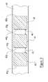
- FIG. 3is an illustrative view of a tape, showing a plurality of portions of the tape from which ink has been removed.
- the printing apparatus 10includes a tape drive shown generally at 11 .
- the printing apparatusincludes a housing 13 , in or on which is mounted a first spool support 12 and a second spool support 14 , which form part of the tape drive 11 .
- a spool of tape 15 , 17is mountable on each of the supports 12 , 14 .
- the spool supports 12 , 14are spaced laterally from one another.
- the printing apparatus 10also includes a printhead 19 for transferring ink from the tape to a substrate 21 which is entrained around a roller 23 adjacent the printhead 19 .
- the substrate 21may be positioned adjacent the printhead 19 on a platen, rather than a roller.
- Each of the spool supports 12 , 14is independently drivable by a respective motor 16 , 18 .
- Each of the motors 16 , 18is a brushless DC motor.
- Each of the spool supports 12 , 14is rotatable clockwise and anti-clockwise by means of its respective motor 16 , 18 .
- Each motor 16 , 18is electrically connected to a controller 24 via a sensor 20 , 22 . This sensor is typically a rotary encoder although it will be appreciated that other technologies are perfectly acceptable.
- the controller 24is operable to control the mode of operation of each of the motors 16 , 18 and the amount of drive provided by each of the motors 16 , 18 .
- Each sensor 20 , 22enables the controller 24 to determine the angular position and rotational speed of a rotor of the respective motor 16 , 18 .
- Information relating to the current drawn by each motor 16 , 18is provided to the controller 24 .
- the motors 16 , 18 , the sensors 20 , 22 and the controller 24all form part of a motor control system 25 .
- the controller 24receives inputs relating to a demanded position of each motor 16 , 18 to advance the tape to a required position, the actual position of the motor 16 , 18 , the measured velocity of each motor 16 , 18 , the current drawn by the motor 16 , 18 , and a torque bias T B required by the motor at a given point in time.
- a supply spool 17upon which unused tape is wound, is mounted on the spool support 14
- a take up spool 15upon which used tape is wound, is mounted on the spool support 12 .
- the tapegenerally advances in a tape path between the supply spool 17 towards the take up spool 15 .
- the tapeis guided in the tape path between the spools 15 , 17 adjacent the printhead 19 by guide members 26 .
- the tape drive 11requires calibration before printing operations can commence. Such calibration is generally required when the printing apparatus 10 is switched on, and when the spools of tape 15 , 17 are replaced.
- the calibration processincludes determining an initial estimate of the diameters of each of the spools of tape 15 , 17 mounted on the spool supports 12 , 14 .
- An example of a suitable method of obtaining such an estimateis described in detail in the applicant's patent GB2310405, also published as U.S. Pat. No. 5,921,689.
- tapepasses from one spool to the other, for example from the supply spool 15 to the take up spool 17 , it passes over a roller of known diameter.
- the rolleris preferably one of the guide members 26 .
- Tapeis drawn from the supply spool 17 , with the motor 16 which drives the take-up spool support 12 operating in position control mode.
- the motor 18which drives the supply spool support 14 operates in torque control mode to deliver a predetermined torque.
- the motor control system 25maintains and updates values for the diameters of the spools 15 , 17 by monitoring the amount of tape transferred from the supply spool to the take-up spool.
- the controller 25takes into account the thickness of the tape to compute an expected change in the diameters of the spools 15 , 17 over a period of time. This technique relies on the tension in the tape being kept substantially constant during printing operations and advancement of the tape between the spools 15 , 17 .
- the motor control system 25When the tape is at rest, the motor control system 25 maintains the desired tape tension by operating one motor, for example the supply spool motor 18 , in a first control mode, in which position is a dominant control parameter.
- This first control modewill be referred to herein as “position control mode”.
- the other motorfor example the take up spool motor 16 , is operated in a second control mode, in which the dominant control parameter is torque.
- the second control modewill be referred to herein as “torque control mode”.
- One motor 18ensures that the absolute position of the tape relative to the printhead 19 is accurately controlled, whilst the other motor 16 maintains the tension in the tape at the desired predetermined value.
- a demanded position P D of the motor 18is received by an S-curve generator 28 , an output of which is used, along with an actual position P A of the motor 18 in an algorithm, preferably a PID algorithm, applied by an electronic filter 29 to determine the change in position required to be carried out by the motor 18 .
- An actual velocity V A of the motoris input to a second electronic filter 31 , which performs an algorithm, again preferably a PID algorithm, and an output of the second electronic filter 31 is used in conjunction with an output of the first electronic filter 29 , relating to the change in position of the motor 18 , to determine a demanded torque T D to be provided by the motor 18 .
- a demanded torque T D and the amount of current A drawn by the motor 18are fed back to a torque controller 30 to provide a control output to the motor 18 .
- the algorithms implemented by the filters 29 , 31are described as being PID algorithms, it will be appreciated that any Linear Time Invariant filter function may be used.
- the motor 16 being operated in torque control modedoes not use inputs relating to demanded position P D or actual position P A of the motor 16 .
- the inputs relating to actual velocity V Amay also be disregarded.
- the torque controller 30receives a torque demand T D based only on the torque bias T B , and optionally upon the actual velocity V A of the motor 16 .
- the current A of the motor 16may also be fed back to the torque controller 30 to generate a control output for the motor 16 .
- the intention of the torque bias T Bis to apply a torque offset to the motor 18 , which is in position control mode, to completely counteract the constant torque provided by the other motor 16 , which is in torque control mode.
- the motor 18 in position control modeis only required to produce an instantaneous torque which will hold that motor 18 in position and does not need to compensate for the torque applied by the other motor 16 . So if, for example, the motor 16 in torque control mode is applying 3N to the ribbon, the motor 18 in position control mode will have a torque bias applied to generate the equivalent of 3N to balance the tension in the tape.
- the controller 25causes both of the motors 16 , 18 to operate in position control mode.
- the transition of the motor 16 which was previously operated in torque control mode into position control modeis smooth. This transition from torque control mode to position control mode is carried out by gradually reducing the torque bias T B to a nominal value, which may be zero.
- the two motors 16 , 18advance the tape accurately along the tape path past the printhead 19 , using the values of the diameters of the spools 15 , 17 and a co-ordinated moving target position.
- the co-ordinated moving target positionis arrived at by the control system 25 determining the desired position of the tape at a point in time, and the controller 24 controls the motors 16 , 18 to achieve this desired position of the tape.
- the amount of tape fed into the tape path from the supply spool 17is desirable for the amount of tape fed into the tape path from the supply spool 17 to be equal to the amount of tape taken up by the take up spool 15 , in order to maintain the tape tension substantially constant.
- thisis difficult to achieve in known tape drives because disturbances of the tape which occur during printing operations, and the fact that the spools 15 , 17 are not perfectly cylindrical mean that the control of the motors 16 , 18 is based upon inaccurate estimates, and thus the tension is unlikely to be kept as near to constant as desired.
- the smooth transition of the take up motor from position control mode to torque control modeprevents the accumulation of such errors increasing long term drift in the ribbon tension.
- one of the spool motors 16 , 18smoothly transitions from position control mode to torque control mode, by increasing the torque bias T B relating to the motor 16 , whilst the other spool motor, for example the supply spool motor 18 , remains in position control mode.
- Gradually increasing the torque bias T B from zero during deceleration of the tapecauses a smooth transition of the motor from position control mode to torque control mode, before the inputs relating to position P A , P D are disregarded.
- the other motorin this case the supply spool motor 18 , remains in position control mode, however the value of torque bias T B applied to this motor may be adjusted, so as to compensate for the increase in torque which is likely to be caused as a result of switching the take up spool motor 16 into torque control mode.
- torque bias T Bit may be possible to retain a constant torque bias T B irrespective of whether the motors 16 , 18 are stationary or in motion, however, the desired torque bias T B will be such that it causes the tension in the tape to remain substantially constant, by the two motors 16 , 18 applying equal and opposite forces on the tape.
- the motor control system 25is capable of testing the accuracy of its control of the advancement of the tape in two ways.
- the first method of testingis to determine the ratio of the torques applied to the two motors 16 , 18 when the tape drive 11 is stationary. In such a situation, one motor 16 , 18 is stationary, whilst the other motor 16 , 18 supplies a torque so as to maintain its position, and to maintain the tension in the tape.
- the ratio of the torquesshould be the same as the ratio of the diameters of the spools 15 , 17 at that time.
- the second method of testingis carried out as the tape drive 11 is completing a movement of the tape.
- the controller 24monitors the angular position change of take up spool motor 16 between its expected target position and its rest position at the correct ribbon tension, using the sensor 20 .
- the angular position change that occurs together with the spool diametergives a measure of the disturbances and errors in the position control of the motor 16 .
- control system 25is iterative, in that it takes into account the results of the testing method(s) carried out over a number of tape advancements (printing cycles) to correct the estimate of the diameters of the spools 15 , 17 for future printing cycles.
- the method of operation of the tape drive 11 described aboveretains the supply spool motor 18 in position control, as the supply spool 17 is more likely to be cylindrical than the take up spool, the tape on the supply spool 17 not having been unwound, and ink removed from it before being rewound on a different spool. Therefore this mode of operation is more likely to provide accurate positioning of the tape adjacent the printhead 19 .
- either spool motor 16 , 18could be switched to torque control mode during tape advance.
- the control system 25manages the tension of the tape in the tape path. If the tape is in tension when power is removed from the motors 16 , 18 , one or both of the spools 15 , 17 will be accelerated by the force exerted by the tension in the tape. Even when the tape is no longer in tension, the or each spool 15 , 17 which has been accelerated will continue to rotate owing to the momentum of the spool(s) 15 , 17 , and tape may spill from the printing apparatus 10 . Of course, this is undesirable, and unacceptable.
- control system 25operates at least one of the motors 16 , 18 , so as to enable a controlled release of tension from the tape, before power is removed from the motors 16 , 18 .
- a mechanical devicemay be used to inhibit or prevent the acceleration of the spools 15 , 17 upon removal of power from the motors 16 , 18 .
- FIG. 3shows a portion of a tape 40 which is suitable for use in a printing apparatus.
- the tape drive 11is to be used in a thermal transfer printing apparatus
- the tape 40 to be transferredis an inked tape, which is substantially uniformly covered with a marking material, e.g. ink, and the printhead 19 is a thermal print head.
- a marking materiale.g. ink
- a first portion 42 of the tape 40is positioned adjacent the printhead 19 , and ink on the first portion 42 of the tape 40 is transferred from the tape 40 to an adjacent substrate 21 .
- the inkis removed from the first portion 42 during the first printing operation, in a pattern so as to produce a desired image on the substrate 21 .
- the imagemay include text and/or any other pattern, for example a barcode.
- the first portion 42 of the tape 40has a leading edge 42 a and a trailing edge 42 b , each of which defines an extent of the image being printed.
- a second portion 44 of the tape 40is positioned adjacent the printhead 19 , such that pixels of ink can be removed from the second portion 44 to print a second image.
- the second portion 44is similar to the first portion 42 and has a leading edge 44 a and a trailing edge 44 b.
- the movement of the tape 40 relative to the printhead 19is accurately controlled by the motor control system 25 , using the method described above, such that a spacing 43 between the adjacent portions of tape 42 , 44 from which ink is removed in successive printing operations is less than 0.5 mm.
- the spacing 43is 0.25 mm.
- the spacingis the distance between the trailing edge 42 b of the first portion and the leading edge 44 a of the second portion 44 of the tape 40 .
- a third portion 46 of tape 40is positioned adjacent the printhead 19 , such that pixels of ink may be removed from the third portion 46 , to print a third image on to the substrate 21 .
- the third portionhas a leading edge 46 a and a trailing edge 46 b .
- a spacing 45between the trailing edge 44 b of the second portion of tape 40 and the leading edge 46 a of the third portion 46 of the tape 40 , is also less than 0.5 mm, and is preferably 0.25 mm.
- any number of printing operationsmay be carried out in succession, and it will be understood that pixels of ink from adjacent portions 42 , 44 , 46 of the tape 40 need not be removed in consecutive printing operations.
- the term “successive”, when used herein,is intended to include, but not be limited to consecutive printing operations.
- the order in which ink is removed from the portions 42 , 44 , 46 of tapeis not important. For example, ink may be removed from the first portion 42 , then the third portion 46 , and then the tape may be positioned such that ink is removed from the second, intermediate portion 44 .
- Each edge 42 a , 42 b , 44 a , 44 b , 46 a , 46 b of each portion of tape 42 , 44 , 46is an imaginary line which extends along the width of the tape, and its position is determined by the extent of the image which is to be printed from the portion 42 , 44 , 46 of the tape 40 .
- Each edge 42 a , 42 b , 44 a , 44 b , 46 a , 46 bis shown as a generally straight line, but it will be appreciated that an image which is printed from each portion of tape need not have straight edges, and a part only of the image to be printed may extend to either or both edges 42 a , 42 b , 44 a , 44 b , 46 a , 46 b of the portion 42 , 44 , 46 from which the image is being printed.
- the size of each portion 42 , 44 , 46is determined by the maximum extent of the each image to be printed.
- the accuracy of motor control system 25 and the tape drive 11is such that it is always possible for the spacing between adjacent portions of tape from which ink is removed in successive printing operations to be less than 0.5 mm.
- the spacings 43 , 45 referred toare distances measured along the tape 40 and are not spacings between images printed on a substrate, or spacings between adjacent substrates.
- the invention described aboveenables improved performance when compared with known motor control systems, particularly those which include stepper motors for driving the spool supports.
- known motor control systemsdo not permit the spacing between adjacent images to be so small, and therefore the present invention provides less waste and improved economy for users.
- a userprints a series of 10 mm images from a typical tape having a length of 1100 m, with a spacing of 0.5 mm between adjacent portions of tape from which ink is removed, it is possible for approximately 104,750 images to be printed.
- printing a series of 10 mm images with a 0.25 mm spacing between the portions of tape from which ink is removedenables approximately 107,300 images to be printed from a 1100 m tape. This is an increase of approximately 2550 images per typical tape.
- the closed loop control employed in the tape drive 11allows the tape motion to be constantly adjusted throughout the print cycle so that the actual tape position matches the demands of the control system more accurately. This means the tape position at the start of the print is more accurately controlled and consistent print gaps are delivered, even when the velocity of the substrate on to which the images are to be printed is continually changing.
- a typical thermal transfer printerwhich includes stepper motors for driving the spool supports, printing at 500 mm/s with a 100 mm diameter reel of tape, the motor will be rotating at 1.6 revolutions per second. If the stepper motor drive system is driven by a standard microstepping drive which delivers 1600 steps per motor revolution, the steps will occur at 390 ⁇ s intervals.
- the tape drive described in this inventiontypically employs a control system which completes a control “loop” every 50 ⁇ s, regardless of the diameter of the reel. Therefore the motor position and speed is assessed and can be adjusted far more frequently than in a comparable stepper motor printer.
Landscapes
- Electronic Switches (AREA)
- Impression-Transfer Materials And Handling Thereof (AREA)
Abstract
Description
Claims (18)
Applications Claiming Priority (2)
| Application Number | Priority Date | Filing Date | Title |
|---|---|---|---|
| GB1302542.4AGB2510834B (en) | 2013-02-13 | 2013-02-13 | Printing apparatus and method of operating a printing apparatus |
| GB1302542.4 | 2013-02-13 |
Publications (2)
| Publication Number | Publication Date |
|---|---|
| US20140225971A1 US20140225971A1 (en) | 2014-08-14 |
| US9145000B2true US9145000B2 (en) | 2015-09-29 |
Family
ID=47999058
Family Applications (1)
| Application Number | Title | Priority Date | Filing Date |
|---|---|---|---|
| US14/179,832ActiveUS9145000B2 (en) | 2013-02-13 | 2014-02-13 | Printing apparatus and method of operating a printing apparatus |
Country Status (2)
| Country | Link |
|---|---|
| US (1) | US9145000B2 (en) |
| GB (1) | GB2510834B (en) |
Cited By (2)
| Publication number | Priority date | Publication date | Assignee | Title |
|---|---|---|---|---|
| US9728068B2 (en) | 2013-08-28 | 2017-08-08 | Gecko Health Innovations, Inc. | Devices, systems, and methods for adherence monitoring and devices, systems, and methods for monitoring use of consumable dispensers |
| US11253661B2 (en) | 2012-06-25 | 2022-02-22 | Gecko Health Innovations, Inc. | Devices, systems, and methods for adherence monitoring and patient interaction |
Families Citing this family (1)
| Publication number | Priority date | Publication date | Assignee | Title |
|---|---|---|---|---|
| US11623836B2 (en)* | 2020-12-15 | 2023-04-11 | Toshiba America Business Solutions, Inc. | Grit roller feeder rollers for sticky media |
Citations (42)
| Publication number | Priority date | Publication date | Assignee | Title |
|---|---|---|---|---|
| GB1550218A (en) | 1975-11-03 | 1979-08-08 | Cii Honeywell Bull | Arrangement for driving and tensioning a printing ribbon for a printer |
| GB2022018A (en) | 1978-05-30 | 1979-12-12 | Tektronix Inc | Thermal Transfer Color Printer |
| JPS6287382A (en) | 1985-10-15 | 1987-04-21 | Fuji Xerox Co Ltd | Controller for thermal recorder |
| US4924240A (en) | 1987-11-02 | 1990-05-08 | Alcatel Business Systems, Limited | Feed for thermal printing ribbon |
| JPH04347659A (en) | 1991-05-27 | 1992-12-02 | Tokyo Electric Co Ltd | multicolor label printer |
| US5254924A (en) | 1992-05-22 | 1993-10-19 | Tachi-S Co. Ltd. | Method and device for controlling motor in powered seat |
| US5325115A (en) | 1991-10-30 | 1994-06-28 | Sony Corporation | Ink ribbon for color printer |
| JPH06312568A (en) | 1993-04-30 | 1994-11-08 | Tokyo Electric Co Ltd | Transfer printer |
| GB2289441A (en) | 1994-05-20 | 1995-11-22 | Prestek Ltd | Ink ribbon economy strategy. |
| JPH082078B2 (en) | 1986-11-18 | 1996-01-10 | 富士ゼロックス株式会社 | Manual scanning printer |
| JPH0867045A (en) | 1994-08-30 | 1996-03-12 | Tec Corp | Printer |
| EP0745890A1 (en) | 1995-05-30 | 1996-12-04 | Eastman Kodak Company | Film web motion control system |
| JPH091906A (en) | 1995-06-23 | 1997-01-07 | Hitachi Koki Co Ltd | Ink ribbon control device for printer |
| US5614803A (en) | 1994-07-05 | 1997-03-25 | Nippondenso Co., Ltd. | Inverter control apparatus |
| GB2310405A (en) | 1995-03-15 | 1997-08-27 | Markem Tech Ltd | Method of calibrating a ribbon winding mechanism for a printing apparatus |
| US5751331A (en) | 1994-07-04 | 1998-05-12 | Sharp Kabushiki Kaisha | Ink sheet transfer control apparatus for giving a specified value of tension to ink sheet to implement stable transfer |
| US5921689A (en) | 1995-03-15 | 1999-07-13 | Buckby; Steven | Method of calibrating a ribbon winding mechanism for a printing apparatus |
| EP0947345A2 (en) | 1998-04-03 | 1999-10-06 | Eastman Kodak Company | Thermal printer and method for detecting donor ribbon type and for aligning color patches relative to a print head |
| US5975777A (en) | 1995-11-13 | 1999-11-02 | Markem Technologies Limited | Printing apparatus with a shuttle for moving the printing ribbon |
| FR2783459A1 (en) | 1998-09-21 | 2000-03-24 | Polyprint | Thermal printer ribbon tensioner mechanism having paper feed with ink ribbon passing roller/print mechanism and ribbon tension measurement/ control. |
| US6082914A (en) | 1999-05-27 | 2000-07-04 | Printronix, Inc. | Thermal printer and drive system for controlling print ribbon velocity and tension |
| US6305629B1 (en) | 2000-05-12 | 2001-10-23 | International Business Machines Corporation | Servo error detection of bi-directional reel-to-reel tape drives using fine line tachometers |
| WO2002022371A2 (en) | 2000-09-11 | 2002-03-21 | Zipher Limited | Tape drive and printing apparatus |
| US20030049065A1 (en) | 1999-05-27 | 2003-03-13 | Barrus Gordon B. | Thermal printer with impoved transport, drive, and remote controls |
| WO2003029013A1 (en) | 2001-09-28 | 2003-04-10 | Zipher Limited | Tape drive |
| US6757129B2 (en) | 2001-05-30 | 2004-06-29 | Renesas Technology Corporation | Magnetic disk storage apparatus |
| US6975087B1 (en) | 2004-08-06 | 2005-12-13 | Delphi Technologies, Inc. | Closed-loop control system |
| GB2440676A (en) | 2006-08-03 | 2008-02-06 | Alan Jermyn | Restraint for fork-lift truck |
| US20080219741A1 (en) | 2007-03-07 | 2008-09-11 | Mcnestry Martin | Tape drive |
| US20080219740A1 (en) | 2007-03-07 | 2008-09-11 | Mcnestry Martin | Tape drive |
| US20080217454A1 (en) | 2007-03-07 | 2008-09-11 | Bradley Alan Trago | Tape drive |
| US20080219743A1 (en) | 2007-03-07 | 2008-09-11 | Mcnestry Martin | Tape drive |
| US20080219742A1 (en) | 2007-03-07 | 2008-09-11 | Mcnestry Martin | Tape drive |
| US20090302143A1 (en) | 2008-06-04 | 2009-12-10 | Josephine Faith Bayang | Applying whip effect to magnetic tape exhibiting a tape stick condition |
| US20090309949A1 (en) | 2008-06-11 | 2009-12-17 | Sinfonia Technology Co., Ltd. | Thermal transfer printer |
| US20100089962A1 (en) | 2006-12-22 | 2010-04-15 | Manroland Ag | Method and Device for the Control of a Feed Mechanism |
| US20100172682A1 (en) | 2007-05-31 | 2010-07-08 | Philip Hart | Tape drive |
| GB2478725A (en) | 2010-03-16 | 2011-09-21 | Markem Imaje Ltd | Tape printer having movable guide member to adjust ribbon tension |
| US8317421B2 (en) | 2007-03-31 | 2012-11-27 | Videojet Technologies (Nottingham) Limited | Tape drive tension control |
| GB2493541A (en) | 2011-08-10 | 2013-02-13 | Markem Imaje Ltd | Motor control system using position or torque as dominant control parameter |
| US20130215210A1 (en) | 2011-08-15 | 2013-08-22 | Martin McNestry | Thermal transfer printer |
| US8730287B2 (en) | 2011-06-24 | 2014-05-20 | Datamax-O'neil Corporation | Ribbon drive assembly |
- 2013
- 2013-02-13GBGB1302542.4Apatent/GB2510834B/enactiveActive
- 2014
- 2014-02-13USUS14/179,832patent/US9145000B2/enactiveActive
Patent Citations (68)
| Publication number | Priority date | Publication date | Assignee | Title |
|---|---|---|---|---|
| GB1550218A (en) | 1975-11-03 | 1979-08-08 | Cii Honeywell Bull | Arrangement for driving and tensioning a printing ribbon for a printer |
| GB2022018A (en) | 1978-05-30 | 1979-12-12 | Tektronix Inc | Thermal Transfer Color Printer |
| JPS6287382A (en) | 1985-10-15 | 1987-04-21 | Fuji Xerox Co Ltd | Controller for thermal recorder |
| JPH082078B2 (en) | 1986-11-18 | 1996-01-10 | 富士ゼロックス株式会社 | Manual scanning printer |
| US4924240A (en) | 1987-11-02 | 1990-05-08 | Alcatel Business Systems, Limited | Feed for thermal printing ribbon |
| JPH04347659A (en) | 1991-05-27 | 1992-12-02 | Tokyo Electric Co Ltd | multicolor label printer |
| US5325115A (en) | 1991-10-30 | 1994-06-28 | Sony Corporation | Ink ribbon for color printer |
| US5254924A (en) | 1992-05-22 | 1993-10-19 | Tachi-S Co. Ltd. | Method and device for controlling motor in powered seat |
| JPH06312568A (en) | 1993-04-30 | 1994-11-08 | Tokyo Electric Co Ltd | Transfer printer |
| GB2289441A (en) | 1994-05-20 | 1995-11-22 | Prestek Ltd | Ink ribbon economy strategy. |
| US5908251A (en) | 1994-05-20 | 1999-06-01 | Markem Technologies Ltd. | Method of printing |
| US5751331A (en) | 1994-07-04 | 1998-05-12 | Sharp Kabushiki Kaisha | Ink sheet transfer control apparatus for giving a specified value of tension to ink sheet to implement stable transfer |
| US5614803A (en) | 1994-07-05 | 1997-03-25 | Nippondenso Co., Ltd. | Inverter control apparatus |
| JPH0867045A (en) | 1994-08-30 | 1996-03-12 | Tec Corp | Printer |
| GB2310405A (en) | 1995-03-15 | 1997-08-27 | Markem Tech Ltd | Method of calibrating a ribbon winding mechanism for a printing apparatus |
| US5921689A (en) | 1995-03-15 | 1999-07-13 | Buckby; Steven | Method of calibrating a ribbon winding mechanism for a printing apparatus |
| US6068206A (en) | 1995-05-30 | 2000-05-30 | Eastman Kodak Company | Film web motion control system |
| EP0745890A1 (en) | 1995-05-30 | 1996-12-04 | Eastman Kodak Company | Film web motion control system |
| JPH091906A (en) | 1995-06-23 | 1997-01-07 | Hitachi Koki Co Ltd | Ink ribbon control device for printer |
| US5975777A (en) | 1995-11-13 | 1999-11-02 | Markem Technologies Limited | Printing apparatus with a shuttle for moving the printing ribbon |
| EP0947345A2 (en) | 1998-04-03 | 1999-10-06 | Eastman Kodak Company | Thermal printer and method for detecting donor ribbon type and for aligning color patches relative to a print head |
| EP0947345A3 (en) | 1998-04-03 | 2000-03-08 | Eastman Kodak Company | Thermal printer and method for detecting donor ribbon type and for aligning color patches relative to a print head |
| FR2783459A1 (en) | 1998-09-21 | 2000-03-24 | Polyprint | Thermal printer ribbon tensioner mechanism having paper feed with ink ribbon passing roller/print mechanism and ribbon tension measurement/ control. |
| US6082914A (en) | 1999-05-27 | 2000-07-04 | Printronix, Inc. | Thermal printer and drive system for controlling print ribbon velocity and tension |
| EP1055521A2 (en) | 1999-05-27 | 2000-11-29 | Printronix, Inc. | Thermal printer and drive system |
| US20030049065A1 (en) | 1999-05-27 | 2003-03-13 | Barrus Gordon B. | Thermal printer with impoved transport, drive, and remote controls |
| EP1055521A3 (en) | 1999-05-27 | 2003-05-02 | Printronix, Inc. | Thermal printer and drive system |
| US6305629B1 (en) | 2000-05-12 | 2001-10-23 | International Business Machines Corporation | Servo error detection of bi-directional reel-to-reel tape drives using fine line tachometers |
| US7753605B2 (en) | 2000-09-11 | 2010-07-13 | Zipher Limited | Tape drive and printing apparatus |
| US8221009B2 (en) | 2000-09-11 | 2012-07-17 | Zipher Limited | Tape drive and printing apparatus |
| WO2002022371A3 (en) | 2000-09-11 | 2002-08-01 | Zipher Ltd | Tape drive and printing apparatus |
| US8591127B2 (en) | 2000-09-11 | 2013-11-26 | Videojet Technologies (Nottingham) Limited | Tape drive and printing apparatus |
| US20040146331A1 (en)* | 2000-09-11 | 2004-07-29 | Mcnestry Martin | Tape drive and printing apparatus |
| US8328441B2 (en) | 2000-09-11 | 2012-12-11 | Videojet Technologies (Nottingham) Limited | Tape drive and printing apparatus |
| US7150572B2 (en) | 2000-09-11 | 2006-12-19 | Zippher Limited | Tape drive and printing apparatus |
| US8221010B2 (en) | 2000-09-11 | 2012-07-17 | Zipher Limited | Tape drive and printing apparatus |
| US8096715B2 (en) | 2000-09-11 | 2012-01-17 | Zipher Limited | Tape drive and printing apparatus |
| US8007190B2 (en) | 2000-09-11 | 2011-08-30 | Zipher Limited | Tape drive and printing apparatus |
| WO2002022371A2 (en) | 2000-09-11 | 2002-03-21 | Zipher Limited | Tape drive and printing apparatus |
| US7748917B2 (en) | 2000-09-11 | 2010-07-06 | Zipher Limited | Tape drive and printing apparatus |
| US7722268B2 (en) | 2000-09-11 | 2010-05-25 | Zipher Limited | Tape drive and printing apparatus |
| US7682094B2 (en) | 2000-09-11 | 2010-03-23 | Zipher Limited | Tape drive and printing apparatus |
| US6757129B2 (en) | 2001-05-30 | 2004-06-29 | Renesas Technology Corporation | Magnetic disk storage apparatus |
| WO2003029013A1 (en) | 2001-09-28 | 2003-04-10 | Zipher Limited | Tape drive |
| US6975087B1 (en) | 2004-08-06 | 2005-12-13 | Delphi Technologies, Inc. | Closed-loop control system |
| GB2440676A (en) | 2006-08-03 | 2008-02-06 | Alan Jermyn | Restraint for fork-lift truck |
| US20100089962A1 (en) | 2006-12-22 | 2010-04-15 | Manroland Ag | Method and Device for the Control of a Feed Mechanism |
| WO2008107647A1 (en) | 2007-03-07 | 2008-09-12 | Zipher Limited | Tape drive |
| US20080219742A1 (en) | 2007-03-07 | 2008-09-11 | Mcnestry Martin | Tape drive |
| US20080219743A1 (en) | 2007-03-07 | 2008-09-11 | Mcnestry Martin | Tape drive |
| WO2008107650A1 (en) | 2007-03-07 | 2008-09-12 | Zipher Limited | Tape drive |
| US20080217454A1 (en) | 2007-03-07 | 2008-09-11 | Bradley Alan Trago | Tape drive |
| US20080219740A1 (en) | 2007-03-07 | 2008-09-11 | Mcnestry Martin | Tape drive |
| US8770874B2 (en) | 2007-03-07 | 2014-07-08 | Videojet Technologies (Nottingham) Limited | Tape drive |
| US20080219741A1 (en) | 2007-03-07 | 2008-09-11 | Mcnestry Martin | Tape drive |
| WO2008107642A1 (en) | 2007-03-07 | 2008-09-12 | Zipher Limited | Tape drive |
| GB2448302A (en) | 2007-03-07 | 2008-10-15 | Zipher Ltd | Tape drive control. |
| US8317421B2 (en) | 2007-03-31 | 2012-11-27 | Videojet Technologies (Nottingham) Limited | Tape drive tension control |
| US20100172682A1 (en) | 2007-05-31 | 2010-07-08 | Philip Hart | Tape drive |
| US20090302143A1 (en) | 2008-06-04 | 2009-12-10 | Josephine Faith Bayang | Applying whip effect to magnetic tape exhibiting a tape stick condition |
| US20090309949A1 (en) | 2008-06-11 | 2009-12-17 | Sinfonia Technology Co., Ltd. | Thermal transfer printer |
| GB2478725A (en) | 2010-03-16 | 2011-09-21 | Markem Imaje Ltd | Tape printer having movable guide member to adjust ribbon tension |
| US8730287B2 (en) | 2011-06-24 | 2014-05-20 | Datamax-O'neil Corporation | Ribbon drive assembly |
| US20130039685A1 (en) | 2011-08-10 | 2013-02-14 | Markem-Imaje Limited | Motor Control System |
| WO2013021211A3 (en) | 2011-08-10 | 2013-04-25 | Markem-Imaje Limited | Motor control system |
| WO2013021211A2 (en) | 2011-08-10 | 2013-02-14 | Markem-Imaje Limited | Motor control system |
| GB2493541A (en) | 2011-08-10 | 2013-02-13 | Markem Imaje Ltd | Motor control system using position or torque as dominant control parameter |
| US20130215210A1 (en) | 2011-08-15 | 2013-08-22 | Martin McNestry | Thermal transfer printer |
Non-Patent Citations (18)
| Title |
|---|
| Authorized Officer Athina Nickitas-Etienne, International Preliminary Report on Patentability, International Application No. PCT/GB2012/051954, issued Feb. 11, 2014, 5 pages. |
| Communication from EP Intellectual Property Office dated Jul. 11, 2013, Observations pursuant to Section 21 of the Patents Act 1977, to be published by the USPTO. |
| Communication pursuant to Rule 114(2) EPC dated Oct. 22, 2014, European Patent Application No. 12758588.3, Observations Pursuant to Article 115 EPC. |
| European Patent Application No. 12758588.3, Further Examination Report dated Nov. 26, 2014. |
| European Search Report, Application No. EP 13 19 2034, dated Mar. 25, 2014, 6 pages. |
| Intellectual Property Office, Search Report dated Jan. 17, 2012, GB Application No. GB1113777.5, 3 pages. |
| Intellectual Property Office, Third Party Observations regarding Application No. GB1302462.5, Jan. 6, 2015, 6 pages. |
| Third Party Observations submitted to UK Intellectual Property Office, Application No. GB1302542.4, dated May 15, 2015, 6 pages. |
| U.S. Appl. No. 13/237,802, Final Office Action Summary mailed Jul. 24, 2014, 23 pages. |
| U.S. Appl. No. 13/237,802, Office Action Summary mailed Jan. 2, 2014, 19 pages. |
| U.S. Appl. No. 13/237,802, Office Action Summary mailed Jan. 20, 2015, 17 pages. |
| U.S. Appl. No. 13/237,802, Reply to Action of Jul. 24, 2014, filed Dec. 19, 2014, 9 pages. |
| U.S. Appl. No. 13/237,802, Reply to Action of Jul. 24, 2014, filed Sep. 24, 2014, 9 pages. |
| U.S. Appl. No. 13/237,802, Response to Action of Jan. 2, 2014, filed Apr. 2, 2014, 14 pages. |
| U.S. Appl. No. 14/075,935, Office Action Summary mailed Dec. 26, 2014, 12 pages. |
| U.S. Appl. No. 14/075,935, Reply to Action of Dec. 26, 2014, filed Mar. 26, 2015,7 pages. |
| U.S. Appl. No. 14/179,145, Office Action Summary mailed Apr. 3, 2015, 18 pages. |
| U.S. Appl. No. 14/179,483, Office Action Summary mailed Dec. 5, 2014, 17 pages. |
Cited By (5)
| Publication number | Priority date | Publication date | Assignee | Title |
|---|---|---|---|---|
| US11253661B2 (en) | 2012-06-25 | 2022-02-22 | Gecko Health Innovations, Inc. | Devices, systems, and methods for adherence monitoring and patient interaction |
| US11938265B2 (en) | 2012-06-25 | 2024-03-26 | Gecko Health Innovations, Inc. | Devices, systems, and methods for adherence monitoring and patient interaction |
| US9728068B2 (en) | 2013-08-28 | 2017-08-08 | Gecko Health Innovations, Inc. | Devices, systems, and methods for adherence monitoring and devices, systems, and methods for monitoring use of consumable dispensers |
| US10002517B2 (en) | 2013-08-28 | 2018-06-19 | Gecko Health Innovations, Inc. | Devices, systems, and methods for adherence monitoring and devices, systems, and methods for monitoring use of consumable dispensers |
| US10573161B2 (en) | 2013-08-28 | 2020-02-25 | Gecko Health Innovations, Inc. | Devices, systems, and methods for adherence monitoring and devices, systems, and methods for monitoring use of consumable dispensers |
Also Published As
| Publication number | Publication date |
|---|---|
| GB2510834A (en) | 2014-08-20 |
| US20140225971A1 (en) | 2014-08-14 |
| GB201302542D0 (en) | 2013-03-27 |
| GB2510834B (en) | 2017-01-18 |
Similar Documents
| Publication | Publication Date | Title |
|---|---|---|
| US9975366B2 (en) | Motor control system | |
| US9272531B2 (en) | Tape drive and method of operation of a tape drive | |
| US9144999B2 (en) | Tape drive and method of operation of a tape drive | |
| EP2134549B1 (en) | Tape drive | |
| US20080219743A1 (en) | Tape drive | |
| US8665301B2 (en) | Tape drive and method of operation of a tape drive | |
| CN115091863B (en) | Band Driver and Method | |
| US9145000B2 (en) | Printing apparatus and method of operating a printing apparatus | |
| EP3060486B1 (en) | Labelling machine and method of operation | |
| EP3328652B1 (en) | Printing apparatus and method | |
| US9238375B2 (en) | Tape drive and method of operation | |
| JP2017178587A (en) | Medium feeding device, printer, and control method for medium feeding device | |
| EP3900940B1 (en) | Printing system | |
| JP2010042525A (en) | Printer and method of detecting ribbon diameter of ink ribbon | |
| JP2009274397A (en) | Thermal transfer printer for film | |
| JP2017190213A (en) | Printer and control method for the same |
Legal Events
| Date | Code | Title | Description |
|---|---|---|---|
| AS | Assignment | Owner name:SAGENTIA LIMITED, UNITED KINGDOM Free format text:CONFIRMATORY ASSIGNMENT;ASSIGNORS:ROBERTS, PAUL CHRISTOPHER;GLOAG, JONATHAN MICHAEL;REEL/FRAME:035453/0017 Effective date:20150226 Owner name:MARKEM-IMAJE INDUSTRIES LIMITED, UNITED KINGDOM Free format text:CONFIRMATORY ASSIGNMENT;ASSIGNORS:LAKIN, PHILLIP;STARKEY, SIMON;REEL/FRAME:035453/0009 Effective date:20150226 Owner name:MARKEM-IMAJE INDUSTRIES LIMITED, UNITED KINGDOM Free format text:CONFIRMATORY ASSIGNMENT;ASSIGNOR:SAGENTIA LIMITED;REEL/FRAME:035453/0122 Effective date:20150226 | |
| AS | Assignment | Owner name:DOVER EUROPE SARL, SWITZERLAND Free format text:ASSIGNMENT OF ASSIGNORS INTEREST;ASSIGNOR:MARKEM-IMAJE INDUSTRIES LIMITED;REEL/FRAME:036302/0718 Effective date:20150316 | |
| STCF | Information on status: patent grant | Free format text:PATENTED CASE | |
| MAFP | Maintenance fee payment | Free format text:PAYMENT OF MAINTENANCE FEE, 4TH YEAR, LARGE ENTITY (ORIGINAL EVENT CODE: M1551); ENTITY STATUS OF PATENT OWNER: LARGE ENTITY Year of fee payment:4 | |
| MAFP | Maintenance fee payment | Free format text:PAYMENT OF MAINTENANCE FEE, 8TH YEAR, LARGE ENTITY (ORIGINAL EVENT CODE: M1552); ENTITY STATUS OF PATENT OWNER: LARGE ENTITY Year of fee payment:8 |