US9144528B2 - Wearable cable-driven exoskeleton for functional arm training - Google Patents
Wearable cable-driven exoskeleton for functional arm trainingDownload PDFInfo
- Publication number
- US9144528B2 US9144528B2US13/079,534US201113079534AUS9144528B2US 9144528 B2US9144528 B2US 9144528B2US 201113079534 AUS201113079534 AUS 201113079534AUS 9144528 B2US9144528 B2US 9144528B2
- Authority
- US
- United States
- Prior art keywords
- cables
- user
- limb
- cuffs
- cuff
- Prior art date
- Legal status (The legal status is an assumption and is not a legal conclusion. Google has not performed a legal analysis and makes no representation as to the accuracy of the status listed.)
- Active, expires
Links
- 238000000034methodMethods0.000claimsabstractdescription17
- 238000000554physical therapyMethods0.000claimsdescription15
- 230000000694effectsEffects0.000claimsdescription3
- 238000004804windingMethods0.000claimsdescription3
- 230000007659motor functionEffects0.000claimsdescription2
- 230000008878couplingEffects0.000claims2
- 238000010168coupling processMethods0.000claims2
- 238000005859coupling reactionMethods0.000claims2
- 230000001404mediated effectEffects0.000claims2
- 210000003414extremityAnatomy0.000description27
- 210000005069earsAnatomy0.000description11
- 210000000707wristAnatomy0.000description8
- 208000027418Wounds and injuryDiseases0.000description5
- 210000000245forearmAnatomy0.000description4
- 229910052782aluminiumInorganic materials0.000description3
- XAGFODPZIPBFFR-UHFFFAOYSA-NaluminiumChemical compound[Al]XAGFODPZIPBFFR-UHFFFAOYSA-N0.000description3
- 230000001771impaired effectEffects0.000description3
- 239000004677NylonSubstances0.000description2
- 208000030886Traumatic Brain injuryDiseases0.000description2
- 230000006870functionEffects0.000description2
- 239000000463materialSubstances0.000description2
- 229910052751metalInorganic materials0.000description2
- 239000002184metalSubstances0.000description2
- 229920001778nylonPolymers0.000description2
- 230000009529traumatic brain injuryEffects0.000description2
- 238000010276constructionMethods0.000description1
- 230000006378damageEffects0.000description1
- 230000006735deficitEffects0.000description1
- 210000002310elbow jointAnatomy0.000description1
- 230000003203everyday effectEffects0.000description1
- 208000014674injuryDiseases0.000description1
- 230000002452interceptive effectEffects0.000description1
- 238000012986modificationMethods0.000description1
- 230000004048modificationEffects0.000description1
- 210000003205muscleAnatomy0.000description1
- 230000002232neuromuscularEffects0.000description1
- 230000001144postural effectEffects0.000description1
- 210000000323shoulder jointAnatomy0.000description1
- 238000006467substitution reactionMethods0.000description1
- 210000003857wrist jointAnatomy0.000description1
Images


Classifications
- A—HUMAN NECESSITIES
- A61—MEDICAL OR VETERINARY SCIENCE; HYGIENE
- A61H—PHYSICAL THERAPY APPARATUS, e.g. DEVICES FOR LOCATING OR STIMULATING REFLEX POINTS IN THE BODY; ARTIFICIAL RESPIRATION; MASSAGE; BATHING DEVICES FOR SPECIAL THERAPEUTIC OR HYGIENIC PURPOSES OR SPECIFIC PARTS OF THE BODY
- A61H1/00—Apparatus for passive exercising; Vibrating apparatus; Chiropractic devices, e.g. body impacting devices, external devices for briefly extending or aligning unbroken bones
- A61H1/02—Stretching or bending or torsioning apparatus for exercising
- A61H1/0274—Stretching or bending or torsioning apparatus for exercising for the upper limbs
- A61H1/0277—Elbow
- A—HUMAN NECESSITIES
- A61—MEDICAL OR VETERINARY SCIENCE; HYGIENE
- A61H—PHYSICAL THERAPY APPARATUS, e.g. DEVICES FOR LOCATING OR STIMULATING REFLEX POINTS IN THE BODY; ARTIFICIAL RESPIRATION; MASSAGE; BATHING DEVICES FOR SPECIAL THERAPEUTIC OR HYGIENIC PURPOSES OR SPECIFIC PARTS OF THE BODY
- A61H1/00—Apparatus for passive exercising; Vibrating apparatus; Chiropractic devices, e.g. body impacting devices, external devices for briefly extending or aligning unbroken bones
- A61H1/02—Stretching or bending or torsioning apparatus for exercising
- A61H1/0274—Stretching or bending or torsioning apparatus for exercising for the upper limbs
- B—PERFORMING OPERATIONS; TRANSPORTING
- B25—HAND TOOLS; PORTABLE POWER-DRIVEN TOOLS; MANIPULATORS
- B25J—MANIPULATORS; CHAMBERS PROVIDED WITH MANIPULATION DEVICES
- B25J9/00—Programme-controlled manipulators
- B25J9/0006—Exoskeletons, i.e. resembling a human figure
- B—PERFORMING OPERATIONS; TRANSPORTING
- B25—HAND TOOLS; PORTABLE POWER-DRIVEN TOOLS; MANIPULATORS
- B25J—MANIPULATORS; CHAMBERS PROVIDED WITH MANIPULATION DEVICES
- B25J9/00—Programme-controlled manipulators
- B25J9/10—Programme-controlled manipulators characterised by positioning means for manipulator elements
- B25J9/104—Programme-controlled manipulators characterised by positioning means for manipulator elements with cables, chains or ribbons
- A—HUMAN NECESSITIES
- A61—MEDICAL OR VETERINARY SCIENCE; HYGIENE
- A61H—PHYSICAL THERAPY APPARATUS, e.g. DEVICES FOR LOCATING OR STIMULATING REFLEX POINTS IN THE BODY; ARTIFICIAL RESPIRATION; MASSAGE; BATHING DEVICES FOR SPECIAL THERAPEUTIC OR HYGIENIC PURPOSES OR SPECIFIC PARTS OF THE BODY
- A61H1/00—Apparatus for passive exercising; Vibrating apparatus; Chiropractic devices, e.g. body impacting devices, external devices for briefly extending or aligning unbroken bones
- A61H1/02—Stretching or bending or torsioning apparatus for exercising
- A61H1/0237—Stretching or bending or torsioning apparatus for exercising for the lower limbs
- A—HUMAN NECESSITIES
- A61—MEDICAL OR VETERINARY SCIENCE; HYGIENE
- A61H—PHYSICAL THERAPY APPARATUS, e.g. DEVICES FOR LOCATING OR STIMULATING REFLEX POINTS IN THE BODY; ARTIFICIAL RESPIRATION; MASSAGE; BATHING DEVICES FOR SPECIAL THERAPEUTIC OR HYGIENIC PURPOSES OR SPECIFIC PARTS OF THE BODY
- A61H2201/00—Characteristics of apparatus not provided for in the preceding codes
- A61H2201/16—Physical interface with patient
- A61H2201/1602—Physical interface with patient kind of interface, e.g. head rest, knee support or lumbar support
- A61H2201/165—Wearable interfaces
- A—HUMAN NECESSITIES
- A61—MEDICAL OR VETERINARY SCIENCE; HYGIENE
- A61H—PHYSICAL THERAPY APPARATUS, e.g. DEVICES FOR LOCATING OR STIMULATING REFLEX POINTS IN THE BODY; ARTIFICIAL RESPIRATION; MASSAGE; BATHING DEVICES FOR SPECIAL THERAPEUTIC OR HYGIENIC PURPOSES OR SPECIFIC PARTS OF THE BODY
- A61H2201/00—Characteristics of apparatus not provided for in the preceding codes
- A61H2201/50—Control means thereof
- A61H2201/5007—Control means thereof computer controlled
Definitions
- the present inventionrelates to an arm exoskeleton apparatus designed to assist and train arm movements.
- the exoskeletonmay be attached or worn by a user.
- the weight of the exoskeletonis reduced because the bulk of the motors, servos and wire spools are suspended above the user on a frame.
- Strokeis the third leading cause of death among adults in the US and the leading cause of disability.
- the ability to use the wrist and hand to orient and grasp objectsis at most risk in moderately impaired individuals such as those suffering the after effects of a stroke.
- personsneed the ability to position and stabilize the hand at appropriate spatial locations. This ability may be greatly impaired in a person who has suffered a stroke.
- the weight of the motors mounted to the shoulder cuffmay add significant weight to a device for use with a patient who may already be in a somewhat weakened state. Accordingly, there exists a need to develop a device to assist and train arm movements of stroke survivors or subjects with weak musculature that can be worn by the user as an exoskeleton without providing a cumbersome amount of weight that will hinder the user's movement and rehabilitation process.
- the various aspects of the inventiongenerally comprises a limb assistance device and system as well as a method for operating the limb assistance device.
- One exemplary embodimentrelates to a device for assisting a user to articulate a limb, the device having an upper section, a lower section, and at least one joint between the upper and lower section.
- the devicecomprises an exoskeleton with a first cuff adapted to be coupled to the lower section of the user's limb.
- the exoskeletonalso includes a second cuff adapted to be coupled to the upper section of the user's limb.
- the exoskeletonalso includes a third cuff adapted to be coupled to a portion of the user's body above the upper section of the limb.
- the first embodiment of the limb assistance deviceincludes one or more first cables attached to the first cuff and one or more second cables attached to the second cuff. Each of the first and second cables are attached to a cable-specific attachment point on the respective cuff. In one exemplary embodiment, the first and second cables are made of either metal wire or nylon.
- the limb assistance deviceincludes one or more first drivers.
- Each first driveris coupled to one of the first cables.
- Each of the first cableshave a variable length between the first driver and the cable-specific attachment point controlled by the first driver.
- the one or more first driversis located remotely from the exoskeleton.
- the limb assistance devicealso includes one or more second drivers.
- Each second driveris coupled to one of the second cables.
- Each of the second cableshave a variable length between the second driver and the cable-specific attachment point controlled by the second driver.
- the one or more second driversis located remotely from the exoskeleton.
- the first exemplary embodiment of the limb assistance deviceincludes a processor operatively coupled to each of the one or more first drivers and the one or more second drivers.
- the processoris configured to transmit signals for manipulating the drivers to vary the lengths of the first cables and the second cables to guide articulation of the user's limb.
- each driveris a motor having a rotating cylinder attached.
- the cableis configured to be wound and unwound on the rotating cylinder in response to the rotation of the motor.
- each rotating cylindermay be threaded with a groove configured to receive the attached cable therein.
- the rotating cylindercomprises a spool attached to the motor shaft on which the cable is wound.
- the rotating cylindercomprises a threaded motor shaft.
- the devicefurther includes a frame.
- the framedefines a space around the exoskeleton and the drivers are attached to the frame.
- a positioning membermay be used for positioning the user in a fixed location relative to the drivers.
- the limb assistance devicethere may be guides mounted to the third cuff. These guides are used for guiding the first and second cables.
- the limb assistance devicemay be specifically configured to assist a user articulate the user's arm.
- the second cuffis configured to attach to a user's upper arm between a user's elbow and shoulder and the third cuff is configured to attach to the user's shoulder.
- the first cuffmay be configured to attach to a user's forearm between a user's hand and elbow, such as to a user's wrist.
- the devicehas one or more force sensors.
- the force sensorsare configured to measure force transmitted via at least one of the first or second cables and to communicate a measured force signal to the processor.
- the processormay be configured to use the measured force signal as feedback to regulate an amount of assistance provided by the device to the user.
- the processormay be configured to cause the device to operate with a range of assistance forces from a relatively greater amount of force to relatively lesser amount of force.
- Another embodiment of the present inventionrelates to a method of assisting a user to articulate a limb.
- the methodincludes providing a limb assistance device similar to the one described above.
- the exoskeleton of the deviceis then coupled to the user's limb.
- a signalis transmitted from the processor to one or more of the first and second drivers, causing the one or more drivers to vary the length of one or more of the attached cables to articulate the user's limb from a first position to a second position.
- Another embodiment described hereinrelates to a method for providing physical therapy to a patient to assist the patient regain motor functions for articulation of a limb.
- This methodincludes providing a limb assistance device as described above.
- the exoskeleton of the limb assistance deviceis then coupled to the patient's limb.
- Signalsare then transmitted from the processor to one or more of the first and second drivers, causing the one or more drivers to vary the length of one or more of the attached cables to articulate the user's limb from a first position to a second position. This step is then repeated for a plurality of different first positions and second positions as part of a physical therapy regime.
- all of the steps of the methodare performed in a first physical therapy session with the processor set to provide a first relatively greater amount of assistance force to the patient.
- the stepsare then repeated in a second physical therapy session, subsequent to the first physical therapy session, with the processor set to provide a second relatively lesser amount of assistance force to the patient.
- all of the stepsare repeated in a plurality of physical therapy sessions while gradually reducing the amount of assistance force from session to session until the user has regained a desired amount of motor control of the articulated limb.
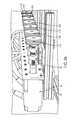
- FIG. 1is a perspective view of the frame, exoskeleton, and motors of one embodiment of the present invention
- FIG. 2is an enlarged perspective view of the exoskeleton illustrated in FIG. 1 ;
- FIG. 2Ais an enlarged perspective view of exemplary attachment ears attached to an exemplary cuff of the exoskeleton
- FIG. 2Bis an enlarged side view of an exemplary extension used with this exoskeleton
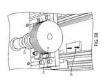
- FIG. 3Ais an enlarged side-perspective view of the motors and threaded cylinders according to a first embodiment of the present invention
- FIG. 3Bis an enlarged top-perspective view of a single threaded cylinder according to a first embodiment of the present invention
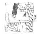
- FIG. 4Ais an enlarged side-perspective view of a single motor and threaded rod according to a second embodiment of the present invention.
- FIG. 4Bis an enlarged side-perspective view of a single threaded rod according to a second embodiment of the present invention.
- the present inventionrelates to a cable-driven upper arm exoskeleton.
- one embodiment of the inventiongenerally includes a frame 100 that defines a space within which the user may either stand or sit. Connected to frame 100 and inside the space defined by frame 100 is exoskeleton 200 .
- Exoskeleton 200includes three cuffs 210 , 220 , 230 , shown in FIG. 2 .
- Cables 202attached at a first end to threaded spools 310 as shown in FIGS. 3A and 3B , drive exoskeleton 200 .
- Cables 202may be made of metal, nylon or any other such material as is known in the art.
- the term “cable” as used hereinis intended to encompass any materials of construction.
- Threaded spools 310are attached to drive shafts 322 of motors 320 .
- Motors 320are supported by aluminum frame 100 and are located in an area adjacent to exoskeleton 200 . As shown in FIG. 1 , motors 320 and threaded spools 310 are located on a rack mounted to frame 100 above the exoskeleton.
- the exoskeletonattaches to a user's arm via three cuffs 210 , 220 , 230 .
- the user's armmay be manipulated through a series of movements or exercises controlled by motors 320 , cables 202 and exoskeleton 200 .
- the embodiment described hereinuses motors with rotating shafts to vary the length of the cables extended between the attachment points on the motors and the attachment points on the cuffs, the invention is not limited to any particular type of driver for varying the length of the cables.
- cuff 230is attached to the “user” between the user's hand and elbow.
- cuff 230is attached to the “user's” wrist.
- Cables 202are wound into the threads on spools 310 to prohibit tangling of cables 202 .
- the second end of each cable 202is connected to one of the three cuffs 210 , 220 , 230 .
- Cuffs 210 , 220 , 230may include extensions 212 , 222 or attachment ears 224 , 234 located on the circumference of the cuffs to provide attachment points for the cables 202 .
- the cablesmay be directed through the extensions 212 , 222 , preventing the cables from becoming entangled and interfering with the operation of the exoskeleton.
- the second ends of the cablesare attached to attachment ears 224 , 234 .
- the positions of attachments ears 224 , 234 along the circumference of cuffs 220 , 230are preferably adjustable to permit location of the ears in an optimum location for different users or different uses of the exoskeleton.
- An enlarged view of the attachment ears 224 , 234is shown in FIG. 2A .
- the attachment earsmay be tightened by screws 225 to be secured in place. Loosening screws 225 allow the attachment ears 224 , 234 to be moved around the circumference of the cuffs 220 , 230 .
- Other variations of the attachment ears 224 , 234that allow their position to be adjusted around the circumference of the cuff, may also be used. Adjustability also helps to prevent possible entanglement of the cables as well as allows for greater comfort for the user.
- a control algorithmallows the exoskeleton to function as a training device in addition to an assistance device.
- This control algorithmassists victims of traumatic brain injuries, for example, in relearning how to move their arm for everyday tasks by helping the user learn from tasks performed using the exoskeleton so that they may eventually perform such tasks without the aid of the exoskeleton.
- the control system of the present inventionalong with a wearable exoskeleton, can provide various levels of assistance to persons with arm movement impairments following stroke, to improve neuromuscular coordination and provide neuro-rehabilitation of persons after traumatic brain injury.
- exoskeleton 200consists of three aluminum cuffs 210 , 220 , 230 which attach to the human user.
- Cuff 210attaches to the user at the shoulder
- cuff 220attaches to the user at the upper arm
- cuff 230attaches to the user at the forearm.
- Shoulder cuff 210is a semicircle shape that rests across the top of the user's shoulder
- Shoulder cuff 210may be equipped with extension pieces 212 .
- An enlarged view of the extension piece 212is shown in FIG. 2B .
- Extension pieces 212include an adjustable eye bolt 216 through which the cable 202 may pass through or be attached to.
- the length of the extension piece 212may include a slot 218 that allows the eyebolt to be moved closer to, or further away from, shoulder cuff 210 .
- shoulder cuff 210includes as many extension pieces 212 as there are motors 320 and threaded spools 310 .
- shoulder cuff 210includes fewer extension pieces 212 than cables 202 , with multiple cables 202 directed through one or more of the extension pieces 212 . For example, as shown in FIG.
- shoulder extensions 212 A- 212 Gare located along shoulder cuff 210 .
- One wire 202 A- 202 Gpasses through each extension piece.
- shoulder extensions 212 A- 212 Dare shown.
- multiple cables 202pass through extension pieces 212 A, 212 B and 212 C.
- the location of the extension pieces 212 on cuff 210may also be adjustable.
- shoulder extensions 212are mounted along grooved track 214 , in which each extension is bolted in place with a pair of bolts 215 , with bolt head 211 adjacent an inside surface of the track with the bolt extending through groove 214 , through a hole in the base of extension 212 , and fastened in place with nut 213 adjacent the base of the extension.
- the number of shoulder extensions 212 used and the locations of the extensionsmay be changed as required by the exercise needed for the user.
- seven cablesare routed through the extension pieces 212 A- 212 D on the upper arm cuff 210 .
- Four of the cables 202are responsible for controlling the three degrees-of-freedom at the shoulder and are attached to attachment ears 224 on upper arm cuff 220 .
- the other three cables 202are routed through the upper arm cuff 220 to attachment ears 234 on cuff 230 for attachment to the user's forearm.
- These three cables 202control the elbow flexion and extension as well as forearm pronation and supination.
- These three cablesalso may be passed through extensions 222 A and 222 B to keep them from becoming entangled and to have them located at the appropriate angle for the exercise or movements required.
- the inventionis not limited to any particular number of cables.
- Load cells 240located near the termination of cables 202 , are electronically connected to processor 130 for providing feedback information relating to the tensions of the cables 202 , as needed.
- MLP-50 Load Cellsavailable from Transducer Techniques of Temecula, Calif., were used as load cells 240 .
- the first ends of cables 202are attached to threaded spools 310 , which wind and unwind cables 202 .
- spools 310 A- 310 Gare coupled to the drive shafts 322 A- 322 G of motors 320 A- 320 G.
- the threads in spools 310keep cables 202 from winding on top of themselves.
- a rubber guide 330 beneath the threaded spool 310guides the cable 202 into the threads of the spool 310 .
- the guidefacilitates precise winding or unwinding of the cables 202 and maintains tension on the cable between the threaded spool 310 at the cable's first end and the attachment point at the cable's second end. Maintaining tension permits accurate cable length estimation from motor encoder data, which is relayed to the processor 130 attached to the motors 320 .
- the processoris configured to estimate arm configuration based upon the length of the cable that has either been wound or unwound.
- threaded rods 410replace the grooved spools depicted in FIGS. 3A and 3B .
- threaded rods 410may comprise the drive shaft of motor 320 , thereby negating the need to attach a threaded spool.
- a slider 430may be mounted onto threaded rod 410 . This slider 430 moves along the threads and keeps a proper distance from the cable being wound or unwound.
- the slider 430comprises a guide, such as eyebolt 432 , that guides cable 202 into the threads.
- motors 320comprise high-torque direct-drive motors 320 electronically connected to processor 130 .
- Motors 320are configured to transmit information to the processor, such as the degree and direction of rotation of the drive shaft 322 .
- motors 320may receive commands from the processor 130 , such as how far to rotate the drive shaft 322 and in which direction to rotate the drive shaft 322 . It is understood to one of skill in the art that motors 320 may be any motor known in the art that can accomplish these tasks described above. In one prototype embodiment depicted in FIGS.
- motors 320were Kollmorgan GoldLine XT AC motors available from Kollmorgan of Radford, Va., powered by a Kollmorgan Servo STAR servo drive, which provided torque, speed and position control.
- the electronics for the systemmay be integrated using a real time control system, such as the NI-PXI control system available from National Instruments Corporation of Austin, Tex.
- each motor 320may also include an encoder that records the movement of its respective motor 320 and transmits a signal to a processor 130 that indicates the distance that respective cable 202 may have moved.
- processor 130is also operatively coupled to motors 320 to transmit signals to motors 320 to selectively release or retain cables 202 as required by the exercise. These signals may be sent by processor 130 from a plurality of preprogrammed tasks contained in processor 130 or they may be manually entered as needed.
- the encoders on motors 320transmit signals to processor 130 to provide information to processor 130 so that processor 130 transmits signals to motors 320 to operate for a proper amount of time.
- load cells 240are electrically connected to processor 130 . Load cells 240 may relay information such as the tension force on the cables 202 as well as the location of the load cells 240 to processor 130 .
- Each position in space reachable by the exoskeletonmay be characterized by a combination of lengths of the cables.
- a preprogrammed taskmay be to use a fork to move food from a plate to the user's mouth.
- the encoders on motors 320transmit information to processor 130 such that processor 130 transmits signals to the correct motors 320 to operate some or all of motors 320 to move smoothly along a predetermined path from a first characterized location with the fork in contact with food on the plate to a second characterized location with the fork adjacent the user's mouth.
- processor 130may be programmed to adjust its assistance over time, from, for example, an assistive device that generates the bulk of the energy and arm manipulation required to complete the required task, to a rehabilitative device that allows the user to self-manipulate his/her arm, with exoskeleton 100 providing less and less support as the user gains strength in the arm.
- processor 130may be attached to frame 100 or located within the space defined by frame 100 such that it may be accessed by either the user or another person directly helping the user. In another embodiment, processor 130 may be located outside of the space defined by the frame and may not be accessed by the user. Finally, it is understood that processor 130 may be connected via wires or connected wirelessly to motors 320 , load cells 240 and any encoders.
- the motors 320 and threaded spools 310are mounted to a frame 100 that defines a space in which the user may stand or sit.
- the exoskeleton 200is placed within this space.
- motors 320 and threaded spools 310may be permanently attached to the frame such that they are secured in place at all times.
- motors 320 and threaded spools 310may be attached to the frame such that they may be moved around to accommodate different users and or different activities.
- the exoskeletonmay be anchored to a positioning member such as post 250 shown in FIGS. 1 and 2 .
- Post 250is configured to position a user in a standing position relative to the frame and may be affixed to the ground in a specific location relative to frame 100 .
- the positioning membermay instead be a configured to position the user in a sitting position, such as a positioning member integrated with or adjacent to a chair.
- the position of the usermay be fixed or unfixed relative to the post 250 .
- the post 250is fixed, the relative lengths of the cables corresponding to a certain position for the user may be generally repeatable. In particular, if a user participates in a sequence of physical therapy sessions spaced over a period of days, weeks, months, or even years, information related to positioning of the user when used in conjunction with a fixed positioning member will be constant relative to the fixed positions of the drivers.
- the post 250as shown in FIG. 2 is fixed to the ground.
- a supporting barmay be substituted for the post and the supporting bar may be suspended on the aluminum frame.
- the threaded cylinders 310 and motors 320may be mounted directly to any area surrounding a space in which the user may stand or sit.
- the cylinders 310 and motors 320may be directly mounted to a wall, ceiling, floor, or other such surrounding structure.
- This embodiment of the inventioneliminates the need for frame 100 . What is important, however, is that the motors are located remotely from the exoskeleton (not mounted on it or otherwise attached to it), thereby removing the weight associated with the motors from being carried by the patient. In an alternative embodiment, the motors may be attached to the positioning member.
- exoskeleton shown and described hereinis configured for use with an upper body limb (shoulder-upper arm-elbow-forearm-wrist-hand) of a user, the same principles described herein may be configured for use in connection with a user's lower body limb (hip-thigh-knee-shin-angle-foot),
Landscapes
- Health & Medical Sciences (AREA)
- Epidemiology (AREA)
- Pain & Pain Management (AREA)
- Physical Education & Sports Medicine (AREA)
- Rehabilitation Therapy (AREA)
- Life Sciences & Earth Sciences (AREA)
- Animal Behavior & Ethology (AREA)
- General Health & Medical Sciences (AREA)
- Public Health (AREA)
- Veterinary Medicine (AREA)
- Engineering & Computer Science (AREA)
- Robotics (AREA)
- Mechanical Engineering (AREA)
- Manipulator (AREA)
- Rehabilitation Tools (AREA)
Abstract
Description
Claims (17)
Priority Applications (1)
| Application Number | Priority Date | Filing Date | Title |
|---|---|---|---|
| US13/079,534US9144528B2 (en) | 2008-09-26 | 2011-04-04 | Wearable cable-driven exoskeleton for functional arm training |
Applications Claiming Priority (4)
| Application Number | Priority Date | Filing Date | Title |
|---|---|---|---|
| US10040708P | 2008-09-26 | 2008-09-26 | |
| US12/568,541US8409118B2 (en) | 2008-09-26 | 2009-09-28 | Upper arm wearable exoskeleton |
| US32047010P | 2010-04-02 | 2010-04-02 | |
| US13/079,534US9144528B2 (en) | 2008-09-26 | 2011-04-04 | Wearable cable-driven exoskeleton for functional arm training |
Related Parent Applications (1)
| Application Number | Title | Priority Date | Filing Date |
|---|---|---|---|
| US12/568,541Continuation-In-PartUS8409118B2 (en) | 2008-09-26 | 2009-09-28 | Upper arm wearable exoskeleton |
Publications (2)
| Publication Number | Publication Date |
|---|---|
| US20110245738A1 US20110245738A1 (en) | 2011-10-06 |
| US9144528B2true US9144528B2 (en) | 2015-09-29 |
Family
ID=44710487
Family Applications (1)
| Application Number | Title | Priority Date | Filing Date |
|---|---|---|---|
| US13/079,534Active2032-09-18US9144528B2 (en) | 2008-09-26 | 2011-04-04 | Wearable cable-driven exoskeleton for functional arm training |
Country Status (1)
| Country | Link |
|---|---|
| US (1) | US9144528B2 (en) |
Cited By (17)
| Publication number | Priority date | Publication date | Assignee | Title |
|---|---|---|---|---|
| US20150119998A1 (en)* | 2012-06-04 | 2015-04-30 | Commissariat a L"energie atomique et aux energies alternatives | Exoskeleton arm having an actuator |
| US10058994B2 (en) | 2015-12-22 | 2018-08-28 | Ekso Bionics, Inc. | Exoskeleton and method of providing an assistive torque to an arm of a wearer |
| US10081103B2 (en) | 2016-06-16 | 2018-09-25 | International Business Machines Corporation | Wearable device testing |
| US10278883B2 (en) | 2014-02-05 | 2019-05-07 | President And Fellows Of Harvard College | Systems, methods, and devices for assisting walking for developmentally-delayed toddlers |
| US10427293B2 (en) | 2012-09-17 | 2019-10-01 | Prisident And Fellows Of Harvard College | Soft exosuit for assistance with human motion |
| US10434030B2 (en) | 2014-09-19 | 2019-10-08 | President And Fellows Of Harvard College | Soft exosuit for assistance with human motion |
| US10569413B2 (en) | 2015-12-22 | 2020-02-25 | Ekso Bionics, Inc. | Exoskeleton and method of providing an assistive torque to an arm of a wearer |
| USD876654S1 (en) | 2018-04-24 | 2020-02-25 | Ossur Iceland Ehf | Posterior strut |
| US10843332B2 (en) | 2013-05-31 | 2020-11-24 | President And Fellow Of Harvard College | Soft exosuit for assistance with human motion |
| US10864100B2 (en) | 2014-04-10 | 2020-12-15 | President And Fellows Of Harvard College | Orthopedic device including protruding members |
| US10918559B2 (en) | 2017-04-25 | 2021-02-16 | Ossur Iceland Ehf | Interface system in an exoskeleton |
| US11000439B2 (en) | 2017-09-28 | 2021-05-11 | Ossur Iceland Ehf | Body interface |
| US11014804B2 (en) | 2017-03-14 | 2021-05-25 | President And Fellows Of Harvard College | Systems and methods for fabricating 3D soft microstructures |
| IT202000004885A1 (en) | 2020-03-09 | 2021-09-09 | Marco Ceccarelli | Portable cable exoskeleton for elbow motor assistance |
| US11324655B2 (en) | 2013-12-09 | 2022-05-10 | Trustees Of Boston University | Assistive flexible suits, flexible suit systems, and methods for making and control thereof to assist human mobility |
| US11498203B2 (en) | 2016-07-22 | 2022-11-15 | President And Fellows Of Harvard College | Controls optimization for wearable systems |
| US11590046B2 (en) | 2016-03-13 | 2023-02-28 | President And Fellows Of Harvard College | Flexible members for anchoring to the body |
Families Citing this family (7)
| Publication number | Priority date | Publication date | Assignee | Title |
|---|---|---|---|---|
| US9144528B2 (en) | 2008-09-26 | 2015-09-29 | The Trustees Of Columbia University In The City Of New York | Wearable cable-driven exoskeleton for functional arm training |
| US8409118B2 (en)* | 2008-09-26 | 2013-04-02 | University Of Delaware | Upper arm wearable exoskeleton |
| CN111821145B (en)* | 2013-11-29 | 2022-12-06 | 雷克斯生物有限公司 | Walking aid |
| US9662526B2 (en) | 2014-04-21 | 2017-05-30 | The Trustees Of Columbia University In The City Of New York | Active movement training devices, methods, and systems |
| CN109106558A (en)* | 2018-09-07 | 2019-01-01 | 南京伟思医疗科技股份有限公司 | A kind of flexible joint exoskeleton robot and its control method |
| WO2021261624A1 (en)* | 2020-06-25 | 2021-12-30 | 엘지전자 주식회사 | Sensing device for muscular strength assisting apparatus |
| CN119458282A (en)* | 2024-11-22 | 2025-02-18 | 中国科学院沈阳自动化研究所 | A feedforward-admittance control method for rope-driven exoskeleton |
Citations (13)
| Publication number | Priority date | Publication date | Assignee | Title |
|---|---|---|---|---|
| US4180870A (en) | 1975-04-15 | 1980-01-01 | Fa Wilh. Jul. Teufel | Universal-orthese |
| US4445502A (en)* | 1979-11-08 | 1984-05-01 | Swan Algernon G | Safety restraint system and inertial reel therefor |
| US5501656A (en) | 1993-08-26 | 1996-03-26 | Agency Of Industrial Science & Technology | Arm motion support apparatus |
| US5601527A (en) | 1995-06-07 | 1997-02-11 | Selkowitz; David M. | spine sling support |
| US5865770A (en) | 1995-12-06 | 1999-02-02 | Schectman; Leonard A. | Device to counteract paralysis |
| US20030120183A1 (en) | 2000-09-20 | 2003-06-26 | Simmons John C. | Assistive clothing |
| US20040106881A1 (en)* | 2002-11-21 | 2004-06-03 | Mcbean John M. | Powered orthotic device |
| US20080161971A1 (en) | 2005-06-21 | 2008-07-03 | Robert Oliver Buckingham | Robotic Arms |
| US20080304935A1 (en) | 2007-05-01 | 2008-12-11 | Scott Stephen H | Robotic exoskeleton for limb movement |
| US7481782B2 (en)* | 2002-09-04 | 2009-01-27 | Northern Sydney Area Health Service | Movement facilitation device |
| US20090192420A1 (en)* | 2008-01-25 | 2009-07-30 | Armstrong Ned B | Reciprocating brace |
| US20110245738A1 (en) | 2008-09-26 | 2011-10-06 | University Of Delaware | Wearable Cable-Driven Exoskeleton for Functional Arm Training |
| US8142379B2 (en) | 2002-09-12 | 2012-03-27 | Universiteit Gent | Orthopedic arm and shoulder brace |
- 2011
- 2011-04-04USUS13/079,534patent/US9144528B2/enactiveActive
Patent Citations (13)
| Publication number | Priority date | Publication date | Assignee | Title |
|---|---|---|---|---|
| US4180870A (en) | 1975-04-15 | 1980-01-01 | Fa Wilh. Jul. Teufel | Universal-orthese |
| US4445502A (en)* | 1979-11-08 | 1984-05-01 | Swan Algernon G | Safety restraint system and inertial reel therefor |
| US5501656A (en) | 1993-08-26 | 1996-03-26 | Agency Of Industrial Science & Technology | Arm motion support apparatus |
| US5601527A (en) | 1995-06-07 | 1997-02-11 | Selkowitz; David M. | spine sling support |
| US5865770A (en) | 1995-12-06 | 1999-02-02 | Schectman; Leonard A. | Device to counteract paralysis |
| US20030120183A1 (en) | 2000-09-20 | 2003-06-26 | Simmons John C. | Assistive clothing |
| US7481782B2 (en)* | 2002-09-04 | 2009-01-27 | Northern Sydney Area Health Service | Movement facilitation device |
| US8142379B2 (en) | 2002-09-12 | 2012-03-27 | Universiteit Gent | Orthopedic arm and shoulder brace |
| US20040106881A1 (en)* | 2002-11-21 | 2004-06-03 | Mcbean John M. | Powered orthotic device |
| US20080161971A1 (en) | 2005-06-21 | 2008-07-03 | Robert Oliver Buckingham | Robotic Arms |
| US20080304935A1 (en) | 2007-05-01 | 2008-12-11 | Scott Stephen H | Robotic exoskeleton for limb movement |
| US20090192420A1 (en)* | 2008-01-25 | 2009-07-30 | Armstrong Ned B | Reciprocating brace |
| US20110245738A1 (en) | 2008-09-26 | 2011-10-06 | University Of Delaware | Wearable Cable-Driven Exoskeleton for Functional Arm Training |
Non-Patent Citations (15)
| Title |
|---|
| Agrawal, Sunil K., "Design and Optimization of a Cable Driven Upper Arm Exoskeleton", Journal of Medical Devices, vol. 3, Transactions of the ASME (Sep. 2009), pp. 031004-1-031004-8. |
| Balasubramanian, Sivakumar, "RUPERT: An Exoskeleton Robot for Assisting Rehabilitation of Arm Functions", Virtual Rehabilitation (2008), 163-167. |
| Ball, Stephen J., "A Planar 3DOF Robotic Exoskeleton for Rehabilitation and Assessment", Proceedings of the 29th Annual International Conference of the IEEE EMBS, (Aug. 23-26, 2007), 4024-4027. |
| Brackbill, Elizabeth A., "Dynamics and Control of a 4-dof Wearable Cable-Driven Upper Arm Exoskeleton", IEEE International Conference on Robotics and Automation (May 12-17, 2009), 2300-2305. |
| Carignan, Craig, "Design of an Arm Exoskeleton with Scapula Motion for Shoulder Rehabilitation", Proceedings of the 12th International Conference on Advanced Robotics, ICAR'05, (2005), 524-531. |
| Carignan, Craig, "Distributed Control and Safety System for a Rehabilitation Arm Exoskeleton", Abstract, ASME Conf. Proc., vol. 9: Mechanical Systems and Control, Parts A, B, and C, Mechanical Systems and Control, Symposium on Advances in Robot Dynamics and Control, Paper No. IMECE 2007-41922 (2007), 1 pg. |
| Gupta, Abhishek, "Design of a Haptic Arm Exoskeleton for Training and Rehabilitation", IEEE/ASME Transactions on Mechatronics, vol. 11, No. 3 (Jun. 2006), 280-289. |
| Ikuta, Koji, "Safety Evaluation Method of Design and Control for Human-Care Robots", International Journal of Robotics Research, vol. 22, No. 5 (May 2003), 281-297. |
| Kiguchi, Kazuo, "Development of a 3DOF Mobile Exoskeleton Robot for Human Upper-Limb Motion Assist", Robotics and Autonomous Systems, vol. 56 (2008), 678-691. |
| Mao, Ying, "Wearable Cable-Driven Upper Arm Exoskeleton-Motion with Transmitted Joint Force and Moment Minimization", IEEE International Conference on Robotics and Automation (May 3-8, 2010), 4334-4339. |
| Martinez F., "Design of a Five Actuated DoF Upper Limb Exoskeleton Oriented to Workplace Help", Proceedings of the 2nd Biennial IEEE/RAS-EMBS International Conference on Biomedical Robotics and Biomechatronics (Oct. 19-22, 2008), 169-174. |
| Perry, Joel C., "Upper-Limb Powered Exoskeleton Design", IEEE/ASME Transactions on Mechatronics, vol. 12, No. 4 (Aug. 2007), 408-416. |
| Roderick, Stephen N., "An Approach to Designing Software Safety Systems for Rehabilitation Robots", Proceedings of the IEEE 9th International Conference on Rehabilitation Robotics (Jun. 28-Jul. 1, 2005), 252-257. |
| Tsagarakis, N. G., "Development and Control of a 'Soft-Actuated' Exoskeleton for Use in Physiotherapy and Training", Autonomous Robots, vol. 15 (2003), 21-33. |
| Yang, Guilin, "Kinematic Design of a 7-DOF Cable-Driven Humanoid Arm: A Solution-in-Nature Approach", Proceedings of the IEEE/ASME International Conference on Advanced Intelligent Mechatronics (Jul. 24-28, 2005), 444-449. |
Cited By (23)
| Publication number | Priority date | Publication date | Assignee | Title |
|---|---|---|---|---|
| US9375325B2 (en)* | 2012-06-04 | 2016-06-28 | Commissariat A L'energie Atomique Et Aux Energies Alternatives | Exoskeleton arm having an actuator |
| US20150119998A1 (en)* | 2012-06-04 | 2015-04-30 | Commissariat a L"energie atomique et aux energies alternatives | Exoskeleton arm having an actuator |
| US11464700B2 (en) | 2012-09-17 | 2022-10-11 | President And Fellows Of Harvard College | Soft exosuit for assistance with human motion |
| US10427293B2 (en) | 2012-09-17 | 2019-10-01 | Prisident And Fellows Of Harvard College | Soft exosuit for assistance with human motion |
| US10843332B2 (en) | 2013-05-31 | 2020-11-24 | President And Fellow Of Harvard College | Soft exosuit for assistance with human motion |
| US11324655B2 (en) | 2013-12-09 | 2022-05-10 | Trustees Of Boston University | Assistive flexible suits, flexible suit systems, and methods for making and control thereof to assist human mobility |
| US10278883B2 (en) | 2014-02-05 | 2019-05-07 | President And Fellows Of Harvard College | Systems, methods, and devices for assisting walking for developmentally-delayed toddlers |
| US10864100B2 (en) | 2014-04-10 | 2020-12-15 | President And Fellows Of Harvard College | Orthopedic device including protruding members |
| US10434030B2 (en) | 2014-09-19 | 2019-10-08 | President And Fellows Of Harvard College | Soft exosuit for assistance with human motion |
| US10569413B2 (en) | 2015-12-22 | 2020-02-25 | Ekso Bionics, Inc. | Exoskeleton and method of providing an assistive torque to an arm of a wearer |
| US10058994B2 (en) | 2015-12-22 | 2018-08-28 | Ekso Bionics, Inc. | Exoskeleton and method of providing an assistive torque to an arm of a wearer |
| US11590046B2 (en) | 2016-03-13 | 2023-02-28 | President And Fellows Of Harvard College | Flexible members for anchoring to the body |
| US10081103B2 (en) | 2016-06-16 | 2018-09-25 | International Business Machines Corporation | Wearable device testing |
| US11498203B2 (en) | 2016-07-22 | 2022-11-15 | President And Fellows Of Harvard College | Controls optimization for wearable systems |
| US11014804B2 (en) | 2017-03-14 | 2021-05-25 | President And Fellows Of Harvard College | Systems and methods for fabricating 3D soft microstructures |
| US10918559B2 (en) | 2017-04-25 | 2021-02-16 | Ossur Iceland Ehf | Interface system in an exoskeleton |
| US11576834B2 (en) | 2017-04-25 | 2023-02-14 | Ossur Iceland Ehf | Interface system in an exoskeleton |
| US12097164B2 (en) | 2017-04-25 | 2024-09-24 | Ossur Iceland Ehf | Interface system in an exoskeleton |
| US11000439B2 (en) | 2017-09-28 | 2021-05-11 | Ossur Iceland Ehf | Body interface |
| US11850206B2 (en) | 2017-09-28 | 2023-12-26 | Ossur Iceland Ehf | Body interface |
| USD942025S1 (en) | 2018-04-24 | 2022-01-25 | Ossur Iceland Ehf | Posterior strut |
| USD876654S1 (en) | 2018-04-24 | 2020-02-25 | Ossur Iceland Ehf | Posterior strut |
| IT202000004885A1 (en) | 2020-03-09 | 2021-09-09 | Marco Ceccarelli | Portable cable exoskeleton for elbow motor assistance |
Also Published As
| Publication number | Publication date |
|---|---|
| US20110245738A1 (en) | 2011-10-06 |
Similar Documents
| Publication | Publication Date | Title |
|---|---|---|
| US9144528B2 (en) | Wearable cable-driven exoskeleton for functional arm training | |
| US7998040B2 (en) | Force assistance device for walking rehabilitation therapy | |
| US20150150706A1 (en) | Cable driven joint actuator and method | |
| US8968220B2 (en) | Wearable robotic system for rehabilitation training of the upper limbs | |
| US8409118B2 (en) | Upper arm wearable exoskeleton | |
| US6796926B2 (en) | Mechanism for manipulating and measuring legs during stepping | |
| US9050486B2 (en) | Anatomical stretching device and methods of use | |
| EP2723458B1 (en) | An apparatus and method for rehabilitating an injured limb | |
| US20180326243A1 (en) | A cable-driven robot for locomotor rehabilitation of lower limbs | |
| KR101099063B1 (en) | Double Arm Rehabilitation Exercise Equipment Using Pneumatic Muscle | |
| US20040097330A1 (en) | Method, apparatus and system for automation of body weight support training (BWST) of biped locomotion over a treadmill using a programmable stepper device (PSD) operating like an exoskeleton drive system from a fixed base | |
| CN103845184A (en) | Rope-driven exoskeleton type upper-limb rehabilitation robot system | |
| US20110137464A1 (en) | Robotic Arm for Controlling the Movement of Human Arm | |
| KR102021744B1 (en) | Appartus for assisting body movement | |
| WO2010140984A1 (en) | Finger function rehabilitation device | |
| CN113367935B (en) | Flexible drive knee joint rehabilitation robot | |
| KR102207991B1 (en) | Flexible Sheet Type Muscular Strength Assisting Suit | |
| US11690773B2 (en) | Wearable upper limb rehabilitation training robot with precise force control | |
| EP3646843B1 (en) | Body movement assistance device | |
| EP4007553B1 (en) | Mirror therapy device | |
| Kubo et al. | Gait rehabilitation device in central nervous system disease: a review | |
| WO2023248194A1 (en) | Modular physiotherapy and rehabilitation device | |
| TWM333178U (en) | Passive upper limb joint rehabilitation device | |
| JPH0515302Y2 (en) | ||
| EP3426358A1 (en) | Apparatus for training, investigating and re-educating neuro-muscular functions in a subject |
Legal Events
| Date | Code | Title | Description |
|---|---|---|---|
| AS | Assignment | Owner name:UNIVERSITY OF DELAWARE, DELAWARE Free format text:ASSIGNMENT OF ASSIGNORS INTEREST;ASSIGNORS:AGRAWAL, SUNIL;MAO, YING;SCHOLZ, JOHN;SIGNING DATES FROM 20110525 TO 20110614;REEL/FRAME:027380/0486 | |
| AS | Assignment | Owner name:SCHOLZ, JOHN, DELAWARE Free format text:ASSIGNMENT OF ASSIGNORS INTEREST;ASSIGNOR:UNIVERSITY OF DELAWARE;REEL/FRAME:033795/0270 Effective date:20140923 Owner name:MAO, YING, NEW YORK Free format text:ASSIGNMENT OF ASSIGNORS INTEREST;ASSIGNOR:UNIVERSITY OF DELAWARE;REEL/FRAME:033795/0270 Effective date:20140923 Owner name:AGRAWAL, SUNIL, DELAWARE Free format text:ASSIGNMENT OF ASSIGNORS INTEREST;ASSIGNOR:UNIVERSITY OF DELAWARE;REEL/FRAME:033795/0270 Effective date:20140923 | |
| AS | Assignment | Owner name:THE TRUSTEES OF COLUMBIA UNIVERSITY IN THE CITY OF Free format text:ASSIGNMENT OF ASSIGNORS INTEREST;ASSIGNORS:AGRAWAL, SUNIL;MAO, YING;SCHOLZ, ELAINE M.;AND OTHERS;SIGNING DATES FROM 20141215 TO 20141216;REEL/FRAME:034568/0301 Owner name:SCHOLZ, ELAINE M., DELAWARE Free format text:LETTERS OF TESTAMENTARY;ASSIGNOR:SCHOLZ, JOHN;REEL/FRAME:034689/0513 Effective date:20131114 Owner name:SCHOLZ, HEATHER A., UTAH Free format text:LETTERS OF TESTAMENTARY;ASSIGNOR:SCHOLZ, JOHN;REEL/FRAME:034689/0513 Effective date:20131114 | |
| STCF | Information on status: patent grant | Free format text:PATENTED CASE | |
| AS | Assignment | Owner name:NATIONAL INSTITUTES OF HEALTH (NIH), U.S. DEPT. OF Free format text:CONFIRMATORY LICENSE;ASSIGNOR:UNIVERSITY OF DELAWARE;REEL/FRAME:044878/0370 Effective date:20171212 | |
| MAFP | Maintenance fee payment | Free format text:PAYMENT OF MAINTENANCE FEE, 4TH YR, SMALL ENTITY (ORIGINAL EVENT CODE: M2551); ENTITY STATUS OF PATENT OWNER: SMALL ENTITY Year of fee payment:4 | |
| AS | Assignment | Owner name:NATIONAL INSTITUTES OF HEALTH - DIRECTOR DEITR, MARYLAND Free format text:CONFIRMATORY LICENSE;ASSIGNOR:UNIVERSITY OF DELAWARE;REEL/FRAME:061544/0242 Effective date:20221026 | |
| MAFP | Maintenance fee payment | Free format text:PAYMENT OF MAINTENANCE FEE, 8TH YR, SMALL ENTITY (ORIGINAL EVENT CODE: M2552); ENTITY STATUS OF PATENT OWNER: SMALL ENTITY Year of fee payment:8 |