US9144437B2 - Bone anchoring assembly - Google Patents
Bone anchoring assemblyDownload PDFInfo
- Publication number
- US9144437B2 US9144437B2US12/488,458US48845809AUS9144437B2US 9144437 B2US9144437 B2US 9144437B2US 48845809 AUS48845809 AUS 48845809AUS 9144437 B2US9144437 B2US 9144437B2
- Authority
- US
- United States
- Prior art keywords
- rod
- channel
- locking element
- pin
- bone anchoring
- Prior art date
- Legal status (The legal status is an assumption and is not a legal conclusion. Google has not performed a legal analysis and makes no representation as to the accuracy of the status listed.)
- Expired - Fee Related, expires
Links
- 210000000988bone and boneAnatomy0.000titleclaimsabstractdescription83
- 238000004873anchoringMethods0.000titleclaimsabstractdescription69
- 239000000463materialSubstances0.000claimsabstractdescription13
- 229920001971elastomerPolymers0.000claimsdescription5
- 239000000806elastomerSubstances0.000claimsdescription5
- 239000002861polymer materialSubstances0.000claimsdescription5
- 238000000034methodMethods0.000claimsdescription4
- 238000003780insertionMethods0.000claimsdescription3
- 230000037431insertionEffects0.000claimsdescription3
- 230000000712assemblyEffects0.000description5
- 238000000429assemblyMethods0.000description5
- 230000008901benefitEffects0.000description3
- 239000000560biocompatible materialSubstances0.000description3
- 238000012986modificationMethods0.000description3
- 230000004048modificationEffects0.000description3
- 239000004033plasticSubstances0.000description3
- 229920003023plasticPolymers0.000description3
- 230000009467reductionEffects0.000description3
- 230000006641stabilisationEffects0.000description3
- 239000007943implantSubstances0.000description2
- 229920001692polycarbonate urethanePolymers0.000description2
- 238000011105stabilizationMethods0.000description2
- 229910001200FerrotitaniumInorganic materials0.000description1
- 239000004696Poly ether ether ketoneSubstances0.000description1
- RTAQQCXQSZGOHL-UHFFFAOYSA-NTitaniumChemical compound[Ti]RTAQQCXQSZGOHL-UHFFFAOYSA-N0.000description1
- JUPQTSLXMOCDHR-UHFFFAOYSA-Nbenzene-1,4-diol;bis(4-fluorophenyl)methanoneChemical compoundOC1=CC=C(O)C=C1.C1=CC(F)=CC=C1C(=O)C1=CC=C(F)C=C1JUPQTSLXMOCDHR-UHFFFAOYSA-N0.000description1
- 230000008878couplingEffects0.000description1
- 238000010168coupling processMethods0.000description1
- 238000005859coupling reactionMethods0.000description1
- -1for exampleSubstances0.000description1
- 230000007794irritationEffects0.000description1
- 210000003041ligamentAnatomy0.000description1
- 229910052751metalInorganic materials0.000description1
- 239000002184metalSubstances0.000description1
- 210000003205muscleAnatomy0.000description1
- 230000000149penetrating effectEffects0.000description1
- 230000035515penetrationEffects0.000description1
- 229920002530polyetherether ketonePolymers0.000description1
- 229920002635polyurethanePolymers0.000description1
- 239000004814polyurethaneSubstances0.000description1
- 230000008569processEffects0.000description1
- 210000004872soft tissueAnatomy0.000description1
- 229910001220stainless steelInorganic materials0.000description1
- 239000010935stainless steelSubstances0.000description1
- 239000010936titaniumSubstances0.000description1
- 230000003313weakening effectEffects0.000description1
Images


Classifications
- A—HUMAN NECESSITIES
- A61—MEDICAL OR VETERINARY SCIENCE; HYGIENE
- A61B—DIAGNOSIS; SURGERY; IDENTIFICATION
- A61B17/00—Surgical instruments, devices or methods
- A61B17/56—Surgical instruments or methods for treatment of bones or joints; Devices specially adapted therefor
- A61B17/58—Surgical instruments or methods for treatment of bones or joints; Devices specially adapted therefor for osteosynthesis, e.g. bone plates, screws or setting implements
- A61B17/68—Internal fixation devices, including fasteners and spinal fixators, even if a part thereof projects from the skin
- A61B17/84—Fasteners therefor or fasteners being internal fixation devices
- A61B17/86—Pins or screws or threaded wires; nuts therefor
- A—HUMAN NECESSITIES
- A61—MEDICAL OR VETERINARY SCIENCE; HYGIENE
- A61B—DIAGNOSIS; SURGERY; IDENTIFICATION
- A61B17/00—Surgical instruments, devices or methods
- A61B17/56—Surgical instruments or methods for treatment of bones or joints; Devices specially adapted therefor
- A61B17/58—Surgical instruments or methods for treatment of bones or joints; Devices specially adapted therefor for osteosynthesis, e.g. bone plates, screws or setting implements
- A61B17/68—Internal fixation devices, including fasteners and spinal fixators, even if a part thereof projects from the skin
- A61B17/70—Spinal positioners or stabilisers, e.g. stabilisers comprising fluid filler in an implant
- A61B17/7001—Screws or hooks combined with longitudinal elements which do not contact vertebrae
- A61B17/7002—Longitudinal elements, e.g. rods
- A61B17/7019—Longitudinal elements having flexible parts, or parts connected together, such that after implantation the elements can move relative to each other
- A61B17/7031—Longitudinal elements having flexible parts, or parts connected together, such that after implantation the elements can move relative to each other made wholly or partly of flexible material
- A—HUMAN NECESSITIES
- A61—MEDICAL OR VETERINARY SCIENCE; HYGIENE
- A61B—DIAGNOSIS; SURGERY; IDENTIFICATION
- A61B17/00—Surgical instruments, devices or methods
- A61B17/56—Surgical instruments or methods for treatment of bones or joints; Devices specially adapted therefor
- A61B17/58—Surgical instruments or methods for treatment of bones or joints; Devices specially adapted therefor for osteosynthesis, e.g. bone plates, screws or setting implements
- A61B17/68—Internal fixation devices, including fasteners and spinal fixators, even if a part thereof projects from the skin
- A61B17/70—Spinal positioners or stabilisers, e.g. stabilisers comprising fluid filler in an implant
- A61B17/7001—Screws or hooks combined with longitudinal elements which do not contact vertebrae
- A61B17/7032—Screws or hooks with U-shaped head or back through which longitudinal rods pass
- A—HUMAN NECESSITIES
- A61—MEDICAL OR VETERINARY SCIENCE; HYGIENE
- A61B—DIAGNOSIS; SURGERY; IDENTIFICATION
- A61B17/00—Surgical instruments, devices or methods
- A61B17/56—Surgical instruments or methods for treatment of bones or joints; Devices specially adapted therefor
- A61B17/58—Surgical instruments or methods for treatment of bones or joints; Devices specially adapted therefor for osteosynthesis, e.g. bone plates, screws or setting implements
- A61B17/68—Internal fixation devices, including fasteners and spinal fixators, even if a part thereof projects from the skin
- A61B17/70—Spinal positioners or stabilisers, e.g. stabilisers comprising fluid filler in an implant
- A61B17/7001—Screws or hooks combined with longitudinal elements which do not contact vertebrae
- A61B17/7035—Screws or hooks, wherein a rod-clamping part and a bone-anchoring part can pivot relative to each other
- A61B17/7037—Screws or hooks, wherein a rod-clamping part and a bone-anchoring part can pivot relative to each other wherein pivoting is blocked when the rod is clamped
Definitions
- the applicationrelates to a bone anchoring assembly for dynamic stabilization of bone or vertebrae.
- a bone anchoring assembly with a flexible rod made of an elastomer materialis known, for example, from EP 1 759 646 A1.
- the rodis held in the receiving part by means of a closure cap and a filling piece which presses onto the rod when the closure cap is screwed onto the receiving part.
- the surface of the filling piece and the bottom of the receiving partincludes, for example, conical pins which press onto the rod and create an indirect form-fit connection which contributes to the frictional connection so as to hold the rod safely in place.
- the indirect form-fit connectionis achieved by a local elastic or plastic deformation of the material of the rod.
- the bone anchoring elementis of the type of a monoaxial screw, wherein the receiving part and the shank are not pivotably connected.
- a bone anchoring assembly with a flexible rodis further known from EP 1 795 134 A1 which describes a polyaxial bone anchoring element.
- the receiving part and the shankare pivotably connected and a pressure element is provided to lock the angular position of the shank relative to the receiving part.
- the surface of the filling piece and that of the pressure element which contacts the rodhas rib-like projections which press onto the flexible rod and provide a form-fit contribution to the fixation of the rod in the receiving part.
- a bone anchoring assembly of the above mentioned typewhich includes a single part closure element instead of a closure element with a filling piece.
- the single part closure elementis an inner screw to be screwed between the legs of the receiving part, which has an annular projection on its lower side which presses onto the flexible rod.
- the bone anchoring assemblies mentioned above which use the flexible rodcomprise an engagement structure to clamp the rod which has sharp edges and/or which has teeth or ribs which are arranged exactly on opposite sides of the rod in order to provide a safe locking.
- the known assembliesare mainly used with rods having a relatively large diameter, for example a diameter of approx. 9 mm or larger.
- rods having a relatively large diameterfor example a diameter of approx. 9 mm or larger.
- bone anchoring assemblies of the type using a flexible rodwhich are small in size, in particular, when the implant is to be placed at a location which is exposed and not covered enough by muscles, ligaments or other soft tissue.
- FR 2 624 720discloses an osteosynthesis device including a bone anchoring element with a shank and a receiving part and a fixation rod which is not flexible but rigid, usually made of a biocompatible metal.
- the fixation rodis held in the receiving part by a locking cap which includes a central pin with a tip penetrating into the surface of the rigid rod. The pin with the tip serves for a provisional fixation of the rod until the locking cap is tightened.
- a bone anchoring assemblyincludes a bone anchoring element with a shank to be anchored in a bone or a vertebra and a receiving part for receiving a rod and a rod which is at least party flexible, the flexible section being made of a polymer material.
- the rodconnects at least two bone anchoring elements.
- the bone anchoring elementincludes a two-piece locking device for allowing a clamping of the rod in two steps by means of pins with a rounded tip.
- the bone anchoring assemblycan be used, for example, with flexible elastomer rods, which have diameters below 9 mm.
- the bone anchoring element, in particular the receiving partcan be downsized. Therefore, a low profile implant is provided which causes the irritation of surrounding body material to be small.
- the pins which contribute to clamp the rodhave a rounded tip of the uppermost portion. Hence, the integrity of the surface of the rod is not violated, since the pins do not scratch the structure.
- the two-step clamping of the rodis safe and effective.
- Mechanical stopsare provided for preventing a penetration of the clamping pins into the surface of the rod due to limitation of the pressure force.
- FIG. 1shows a perspective exploded view of the bone anchoring assembly according to a first embodiment.
- FIG. 2shows a perspective view of the bone anchoring assembly according to FIG. 1 in an assembled state before final clamping of the rod.
- FIG. 3shows a sectional view of the bone anchoring assembly according to the first embodiment, the section being taken perpendicular to the rod axis, wherein the locking device is not yet inserted.
- FIG. 4shows a sectional view of the bone anchoring assembly according to FIG. 3 , the section being taken in a plane containing the rod axis.
- FIG. 5shows a sectional view of the bone anchoring assembly according to FIG. 3 , where the locking device is inserted but not yet tightened.
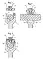
- FIG. 6shows a sectional view of the anchoring device of FIG. 3 , the section being taken perpendicular to the rod axis, wherein the outer locking screw of the locking device is tightened and the inner locking screw of the locking device is not yet tightened.
- FIG. 7shows a sectional view of the bone anchoring assembly shown in FIG. 6 .
- FIG. 8shows a sectional view, the section being taken perpendicular to the rod axis of the bone anchoring assembly in a fully tightened state of the locking device.
- FIG. 9shows a sectional view of the bone anchoring assembly of FIG. 8 , the section being taken in a plane containing the rod axis.
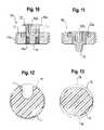
- FIG. 10shows an enlarged sectional view of the locking device with the inner locking screw not yet tightened.
- FIG. 11shows a sectional view of the locking device with the inner locking screw tightened.
- FIG. 12shows a sectional view of the rod according to the first embodiment, the section being taken perpendicular to the rod axis, showing schematically the engagement of the pin of the inner locking screw.
- FIG. 13shows a sectional view of the rod, the section being taken perpendicular to the rod axis in a case where two rib-like teeth engage the rod at opposite sides.
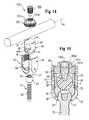
- FIG. 14shows a second embodiment of the bone anchoring assembly in a perspective exploded view.
- FIG. 15shows a sectional view of the bone anchoring assembly according to the second embodiment, the section being taken perpendicular to the rod axis.
- FIGS. 16 and 17show a side view seen along the rod axis and a sectional view along the rod axis of the bone anchoring assembly according to the second embodiment before tightening the inner locking device.
- FIGS. 18 and 19show the bone anchoring assembly according to FIGS. 16 and 17 , respectively, when the inner locking device is tightened.
- the bone anchoring assemblyincludes a bone anchoring element 1 in the form of a monoaxial bone screw having a shank 2 with a bone thread and a tip at one end and a receiving part 3 at the opposite end.
- the receiving part 3is substantially cylindrically-shaped and includes a substantially U-shaped recess 4 forming two free legs 5 , 6 defining a channel for the insertion of the rod.
- An internal thread 7is provided on the legs.
- the bottom of the U-shaped recessforms a seat 8 for receiving a rod 9 .
- the rod 9is used to connect several bone anchoring elements.
- a two piece locking device 10which includes an outer locking screw 11 and an inner locking screw 12 .
- the locking devicecan be screwed between the legs 5 , 6 .
- the receiving part 3includes a shoulder 7 a for forming a stop for the screwing-in for the outer locking element 11 .
- two pins 13 a , 13 bare provided which are located preferably at both ends of the channel.
- the uppermost parts of the pinsare located on a line which is parallel to the longitudinal axis L of the channel.
- the pins 13 a , 13 bare substantially cylindrical and their free end is rounded, preferably semi-spherical. More specifically, the pins are longitudinal rod-shaped pins with a rounded free end.
- the outer locking screw 11 of the locking device 10includes a threaded coaxial bore 11 a into which the inner locking screw 12 can be screwed. As best seen in FIGS. 11 and 12 the outer locking screw 11 has an external thread 11 b , which is preferably in the form of a flat thread cooperating with a flat thread 7 at the inner side of the legs 5 , 6 of the receiving part to prevent splaying of the legs when the outer locking screw 11 is screwed-in.
- the outer locking screw 11further includes an annular coaxial recess 11 c with an engagement structure for engagement with a screwing-in tool (not shown).
- the inner locking screw 12includes at one end an annular projection 12 a , the diameter of which is slightly larger than the inner diameter of the coaxial recess 11 c . As shown in FIG. 11 , when the inner locking screw 12 is screwed-in, the annular projection 12 a abuts against the inner edge of the coaxial recess 11 c preventing further advancement of the inner screw. Hence, a stop is provided for the introduction of the inner locking screw 12 into the outer locking screw 11 . Of course, the stop for the screwing-in of the inner locking screw can be realized otherwise.
- the length of the threaded portion of the inner locking screwcorresponds to the length of the threaded bore of the outer locking screw 11 .
- the inner locking screwfurther has a coaxial circular recess 12 b with an engagement structure for screwing-in the inner locking screw 12 .
- the inner locking screw 12On its side opposite to the annular projection 12 a the inner locking screw 12 includes a coaxial pin 15 for pressing onto the rod 9 .
- the coaxial pin 15projects from the substantially flush lower side of the locking device.
- the pin 15is preferably cylindrical with a semi-spherical free end, more specifically, the pin 15 is a longitudinal rod-shaped pin with a rounded free end and corresponds in its dimension substantially to the dimensions of the pins 13 a and 13 b of the receiving part.
- the pin-shaped projections 13 a , 13 b in the channelare arranged axially offset to the cylinder axis of the pin-shaped projection 15 on the second locking screw.
- the bone anchoring element 1 and the locking device 10are made of a biocompatible material, such as, for example, titanium or stainless steel or another biocompatible material, for example PEEK.
- the rod 9is made at least in part of a flexible biocompatible material, preferably of a plastic material and in particular of an elastomer material.
- a flexible biocompatible materialpreferably of a plastic material and in particular of an elastomer material.
- a materialcan be based on, for example, polycarbonate-polyurethane or polycarbonate-urethane (PCU).
- PCUpolycarbonate-polyurethane
- SIBSstyrene-block-isobutylene-block-styrene
- the roddoes not need to be made totally of one single material but can comprise several materials and inner structures and/or sections with different flexibility/rigidity.
- the flexible sectionis the section which is to be clamped in the receiving part.
- the diameter of the rod 9can be any of the usual diameters of rods for stabilisation of the spine, in particular diameters from 4.5 mm-9 mm.
- first at least two bone anchoring elements 1are screwed into adjacent vertebrae, for example into the pedicles. At least one of the bone anchoring elements is formed according to the first embodiment.
- the rod 9is inserted into the receiving part 3 and fixed.
- the procedure of fixationis now explained with reference to FIGS. 3 to 9 .
- the inner locking screw 12is screwed into the outer locking screw only to an extent such that only a small part of the pin 15 projects from the lower side of the outer locking screw 11 .
- the rod 9is inserted into the channel until it rests onto the pins 13 a , 13 b projecting from the seat 8 .
- the locking device 10is inserted between the legs in such a way that the pin 15 is directed against the rod 9 .
- the inner locking screw 12is tightened.
- the pin 15presses onto the opposite side of the surface of the rod and is immersed into the surface of the rod. Due to the mechanical stops in form of the shoulder 7 a in the receiving part and in form of the cooperation of the annular projection 12 a of the inner locking screw with the edge of the coaxial recess 11 c of the outer locking screw, the pressure force exerted by the pins 13 a , 13 b , 15 onto the surface of the rod is well-defined and cannot be exceeded.
- the dimension of the pins, in particular their height, their diameter and the radius of the free end portionis designed such that under a given pressure force which is limited by the stops, the pins do not violate the integral structure of the rod.
- the arrangement of the pin fixation seen in a direction perpendicular to the longitudinal axis of the rodis a three-point fixation which is particularly safe. Accordingly, there is no clamping on locations which are exactly on opposite sides of the rod which may cause the danger of violating the integral structure of the rod at the clamping site.
- the fixation of the rodtakes place in two steps.
- the rodis fixed from below by means of the pins 13 a , 13 b .
- the rodis fixed from above by the means of the pin 15 . This results in a safe and effective fixation.
- the surface area of the rod in an unclamped condition and in a section perpendicular to the rod axisis nearly unchanged when the pin 15 and the pins 13 a , 13 b are immersed into the rod.
- a clamping of the rod from opposite sides by ribs 19would lead to a considerable reduction of the surface area within the receiving part (reduction from dashed line to full line).
- the reduction of the surface areais significantly less than with ribs. Since the pins 13 a , 13 b in the channel are axially offset to the pin 15 on the second locking element, the cross section of the rod at the clamping site can be maximized.
- FIGS. 14 to 19A second embodiment of the bone anchoring assembly will now be described with reference to FIGS. 14 to 19 . Parts which are identical to the previously described embodiment are indicated with the same reference numerals and the description thereof will not be repeated.
- the bone anchoring assemblyincludes a bone anchoring element 20 , the rod 9 which is identical to the previously described rod and a locking device 100 .
- the bone anchoring elementincludes a bone anchor 21 having a shank 22 to be anchored in the bone and a spherically-shaped head 23 with a recess 24 at the free end for screwing-in the anchor into the bone.
- the receiving part 25is substantially cylindrical and includes a first end 26 and a second end 27 and a coaxial bore 28 extending from the first end 26 to the second end 27 and tapering in an area near the second end such that, as shown in FIG. 15 the head 23 of the anchor is pivotably held in the receiving part at the second end 27 .
- the receiving part 25includes a U-shaped recess 29 extending from the first end 26 in the direction of the second end 27 . With the U-shaped recess 29 two free legs 30 , 31 are formed which include an internal thread 32 .
- a pressure element 33is provided which is substantially cylindrical and dimensioned such that it can be moved within the bore 28 of the receiving part 25 .
- the pressure element 33has a coaxial bore 34 extending through the pressure element and allowing to guide a screwing-in tool therethrough for screwing-in the anchor 21 . It further includes a spherical recess 35 which is adapted to receive the spherical head 23 of the anchor 21 .
- the pressure element 33includes a substantially U-shaped recess 36 extending from its free end in the direction of the spherical recess 35 . By means of the U-shaped recess 36 two free legs 37 , 38 are formed which form the lateral walls of a channel for receiving the rod.
- the pins 40 a , 40 bare provided which are arranged in a similar way as the pins 13 a , 13 b of the first embodiment and which are located in this embodiment at both sides of the bore 34 .
- the pinshave a substantially quadrangular shape and their uppermost portions are semi-cylindrical. However, they can have any shape as long as the uppermost portion is rounded as described in the first embodiment.
- the uppermost portions of the pins 40 a , 40 bare located on a line which is parallel to the longitudinal axis R of the rod.
- the pressure element 33is sized in such a way that the legs 37 , 38 extend slightly above the surface of the rod when the rod is inserted into the channel and the pins 40 a , 40 b are immersed into the surface of the rod 9 .
- the internal thread 32 of the receiving partdoes not have a shoulder on its end but the stop for the locking device is provided by the upper edge 41 of the legs 37 , 38 of the pressure element 33 .
- the locking device 100includes as in the first embodiment an outer locking screw 101 and an inner locking screw 102 .
- the outer locking screw 101differs from the outer locking screw 11 of the first embodiment only in that it includes instead of the recess 11 c for screwing-in a projecting engagement structure 101 c for engagement with a screwing-in tool.
- outer locking screw 101can also be formed identical to the outer locking screw 11 of the first embodiment.
- the outer locking screw 101also includes a coaxial threaded bore 101 a into which the inner locking screw 102 can be screwed.
- the inner locking screw 102is similar to the inner locking screw 12 of the first embodiment. It includes an annular projection 102 a at its one end and a recess 102 b for screwing-in.
- the inner locking screw 102includes at its other end a pin 105 which is shaped like the pin 15 according to the first embodiment.
- the annular projection 102 aabuts against a part of the engagement structure 101 c whereby a stop is formed preventing further screwing-in of the inner locking screw 102 .
- the pin 105projects from the lower side of the locking device.
- the pressure element 33does not fix the angular position of the anchor with respect to the receiving part and the receiving part can be aligned to receive the rod 9 .
- the fixationis described with respect to FIGS. 16 to 19 .
- the locking device 100is assembled in such a way that the inner locking screw 102 is not fully screwed into the outer locking screw 101 .
- the rodis inserted into the channel of the pressure element such that it rests onto the pins 40 a , 40 b .
- the locking device 100is tightened by means of screwing-in the first locking screw 101 until it presses onto the upper edge 41 of the pressure element.
- the whole pressure element with the rodis pressed downward to fix the head 23 in the receiving part 25 so that it can no longer pivot.
- the pins 40 a , 40 bpress onto the lower surface of the rod thereby immersing into the lower surface and fixing the rod in the U-shaped channel of the pressure element.
- the inner locking screw 102is tightened until the annular projection 102 abuts against the engagement structure 101 c .
- the dimensionis such that in this condition the pin 105 is pressed onto and immersed in the surface of the rod without any excess force.
- the fixationis as in the first embodiment a two-step fixation which is safe and effective. In the first step also the head 23 is locked within the receiving part.
- the number of pins in the bottom of the channel of either the receiving part or the pressure elementmay vary. In some cases more than two pins might be of advantage.
- the shape of the pinscan also vary. However, the height of the pin and the radius of the uppermost rounded portion must be designed such that there is no violation of the integral structure of the rod, while simultaneously providing safe fixation.
- the two-part locking devicemay consist of an outer nut and an inner screw with the inner screw having the pin.
- the engagement between the receiving part and the locking devicemust not be a threaded engagement, other forms of engagement such as a bayonet coupling are conceivable.
- polyaxial bone anchoring devicesknown may be conceivable which can be modified so as to have the pins described above.
- a polyaxial screwwhere the bone anchor 21 is inserted from below, a so-called bottom-loader, may be also used.
Landscapes
- Health & Medical Sciences (AREA)
- Orthopedic Medicine & Surgery (AREA)
- Life Sciences & Earth Sciences (AREA)
- Surgery (AREA)
- Neurology (AREA)
- Heart & Thoracic Surgery (AREA)
- Engineering & Computer Science (AREA)
- Biomedical Technology (AREA)
- Nuclear Medicine, Radiotherapy & Molecular Imaging (AREA)
- Medical Informatics (AREA)
- Molecular Biology (AREA)
- Animal Behavior & Ethology (AREA)
- General Health & Medical Sciences (AREA)
- Public Health (AREA)
- Veterinary Medicine (AREA)
- Surgical Instruments (AREA)
Abstract
Description
Claims (18)
Priority Applications (1)
| Application Number | Priority Date | Filing Date | Title |
|---|---|---|---|
| US12/488,458US9144437B2 (en) | 2008-06-19 | 2009-06-19 | Bone anchoring assembly |
Applications Claiming Priority (5)
| Application Number | Priority Date | Filing Date | Title |
|---|---|---|---|
| US7387908P | 2008-06-19 | 2008-06-19 | |
| EP08011203 | 2008-06-19 | ||
| EP20080011203EP2135574B1 (en) | 2008-06-19 | 2008-06-19 | Bone anchoring assembly |
| EP08011203.0 | 2008-06-19 | ||
| US12/488,458US9144437B2 (en) | 2008-06-19 | 2009-06-19 | Bone anchoring assembly |
Publications (2)
| Publication Number | Publication Date |
|---|---|
| US20090318969A1 US20090318969A1 (en) | 2009-12-24 |
| US9144437B2true US9144437B2 (en) | 2015-09-29 |
Family
ID=39940597
Family Applications (1)
| Application Number | Title | Priority Date | Filing Date |
|---|---|---|---|
| US12/488,458Expired - Fee RelatedUS9144437B2 (en) | 2008-06-19 | 2009-06-19 | Bone anchoring assembly |
Country Status (7)
| Country | Link |
|---|---|
| US (1) | US9144437B2 (en) |
| EP (1) | EP2135574B1 (en) |
| JP (1) | JP2010000352A (en) |
| KR (1) | KR101501269B1 (en) |
| CN (1) | CN101606860B (en) |
| ES (1) | ES2375526T3 (en) |
| TW (1) | TWI480019B (en) |
Cited By (9)
| Publication number | Priority date | Publication date | Assignee | Title |
|---|---|---|---|---|
| US20140018867A1 (en)* | 2011-02-04 | 2014-01-16 | Stefan Freudiger | Precaution against jamming on open bone screws |
| US20160361094A1 (en)* | 2015-06-15 | 2016-12-15 | Aesculap Ag | Pedicle screw with radially offset guideway |
| US10485596B2 (en) | 2016-12-06 | 2019-11-26 | Medos International Sàrl | Longitudinally-adjustable bone anchors and related methods |
| US20200390472A1 (en)* | 2019-02-27 | 2020-12-17 | Orthopediatrics Corp. | Bone anchor with cord retention features |
| US20210361325A1 (en)* | 2005-03-24 | 2021-11-25 | DePuy Synthes Products, Inc. | Low profile spinal tethering devices |
| US11337734B2 (en) | 2019-05-22 | 2022-05-24 | Nuvasive, Inc. | Posterior spinal fixation screws |
| US11627992B2 (en) | 2020-12-21 | 2023-04-18 | Warsaw Orthopedic, Inc. | Locking-cap module and connector |
| US11627995B2 (en) | 2020-12-21 | 2023-04-18 | Warsaw Orthopedic, Inc. | Locking-cap module and connector |
| US11957391B2 (en) | 2021-11-01 | 2024-04-16 | Warsaw Orthopedic, Inc. | Bone screw having an overmold of a shank |
Families Citing this family (21)
| Publication number | Priority date | Publication date | Assignee | Title |
|---|---|---|---|---|
| FR2954905B1 (en)* | 2010-01-06 | 2012-12-28 | Implanet | DEVICE FOR FIXING VERTEBRAL |
| EP2606842B1 (en)* | 2010-03-29 | 2018-08-29 | Biedermann Technologies GmbH & Co. KG | Bone anchoring device |
| JP2014507970A (en)* | 2010-12-29 | 2014-04-03 | ロジャー・ピー・ジャクソン | A polyaxial bone anchor having an open flat retainer, pop-on shank, and friction fit insert |
| US8920475B1 (en) | 2011-01-07 | 2014-12-30 | Lanx, Inc. | Vertebral fixation system including torque mitigation |
| EP2554130B1 (en) | 2011-08-05 | 2014-05-28 | Biedermann Technologies GmbH & Co. KG | Locking device for locking a rod-shaped element in a receiving part of a bone anchor and bone anchor with such a locking device |
| US9655655B2 (en)* | 2011-08-16 | 2017-05-23 | Aesculap Implant Systems, Llc | Two step locking screw assembly |
| EP2574296B1 (en) | 2011-09-28 | 2016-03-02 | Biedermann Technologies GmbH & Co. KG | Bone anchoring assembly |
| EP2591738A1 (en)* | 2011-11-14 | 2013-05-15 | Biedermann Technologies GmbH & Co. KG | Polyaxial bone anchoring device |
| ES2549634T3 (en)* | 2012-05-31 | 2015-10-30 | Biedermann Technologies Gmbh & Co. Kg | Polyaxial bone anchoring device |
| US9901379B2 (en)* | 2012-08-24 | 2018-02-27 | Rtg Scientific | Orthopedic fastener device |
| CN103040516A (en)* | 2012-12-27 | 2013-04-17 | 苏州欣荣博尔特医疗器械有限公司 | Dual-locking type polyaxial spinal screw |
| US10548644B2 (en) | 2013-03-05 | 2020-02-04 | Globus Medical, Inc. | Elastic member clamps |
| US10034692B2 (en) | 2013-03-05 | 2018-07-31 | Globus Medical, Inc. | Elastic member clamps |
| US9433441B2 (en)* | 2013-03-05 | 2016-09-06 | Globus Medical, Inc. | Elastic member clamps |
| US9931138B2 (en) | 2014-10-15 | 2018-04-03 | Globus Medical, Inc. | Orthopedic extendable rods |
| CN105581831B (en)* | 2015-12-24 | 2017-03-15 | 建湖县人民医院 | A kind of novel combination type pedicle screw-rod locking system |
| EP3695796B1 (en) | 2019-02-13 | 2022-08-03 | Biedermann Technologies GmbH & Co. KG | Anchoring assembly for anchoring a rod to a bone or a vertebra |
| US11771475B2 (en) | 2020-10-07 | 2023-10-03 | Globus Medical, Inc. | Systems and methods for surgical procedures using band clamp implants and tensioning instruments |
| US11974785B2 (en) | 2020-10-16 | 2024-05-07 | Globus Medical, Inc | Band clamp implants |
| US12213706B2 (en) | 2020-10-07 | 2025-02-04 | Globus Medical, Inc. | Systems and methods for surgical procedures using band clamp implants and tensioning instruments |
| EP4111992B1 (en)* | 2021-07-01 | 2024-01-31 | Biedermann Technologies GmbH & Co. KG | Bone anchoring device |
Citations (53)
| Publication number | Priority date | Publication date | Assignee | Title |
|---|---|---|---|---|
| FR2624720A1 (en) | 1987-12-21 | 1989-06-23 | Fabrication Materiel Orthopedi | Implant for osteosynthesis device, in particular for the spine |
| WO1992003100A1 (en) | 1990-08-21 | 1992-03-05 | Synthes Ag, Chur | Implant for osteosynthesis device, in particular for correcting the vertebral column |
| US5360431A (en)* | 1990-04-26 | 1994-11-01 | Cross Medical Products | Transpedicular screw system and method of use |
| US5443467A (en) | 1993-03-10 | 1995-08-22 | Biedermann Motech Gmbh | Bone screw |
| US5496321A (en) | 1993-11-19 | 1996-03-05 | Cross Medical Products, Inc. | Rod anchor seat having a sliding interlocking rod connector |
| US5536268A (en) | 1992-12-23 | 1996-07-16 | Plus Endoprothetik Ag | System for osteosynthesis at the vertebral column, connecting element for such a system and tool for its placement and removal |
| US6102913A (en) | 1998-10-22 | 2000-08-15 | Jackson; Roger P. | Removeable set screw for medical implant |
| US6179841B1 (en) | 1997-01-06 | 2001-01-30 | Medtronic Sofamor Danek, Incorporated | Set screw for use with osteosynthesis apparatus |
| US6224598B1 (en)* | 2000-02-16 | 2001-05-01 | Roger P. Jackson | Bone screw threaded plug closure with central set screw |
| US6224596B1 (en) | 1997-01-06 | 2001-05-01 | Roger P. Jackson | Set screw for use with osteosynthesis apparatus |
| US20010020168A1 (en)* | 1997-10-06 | 2001-09-06 | Werner Hermann | Shackle element for clamping a fixation rod, a method for making a shackle element, a hook with a shackle element and a rode connector with a shackle element |
| US6454768B1 (en) | 2000-12-05 | 2002-09-24 | Roger P. Jackson | Removable gripping set screw |
| WO2003041601A1 (en) | 2001-11-14 | 2003-05-22 | Synthes Ag Chur | Device for joining a longitudinal support with a bone fixation means |
| US20030125741A1 (en)* | 2001-12-28 | 2003-07-03 | Biedermann Motech Gmbh | Locking device for securing a rod-shaped element in a holding element connected to a shank |
| US6652526B1 (en)* | 2001-10-05 | 2003-11-25 | Ruben P. Arafiles | Spinal stabilization rod fastener |
| US20030220642A1 (en)* | 2002-05-21 | 2003-11-27 | Stefan Freudiger | Elastic stabilization system for vertebral columns |
| US6682530B2 (en)* | 2002-01-14 | 2004-01-27 | Robert A Dixon | Dynamized vertebral stabilizer using an outrigger implant |
| US6730089B2 (en) | 2002-08-26 | 2004-05-04 | Roger P. Jackson | Nested closure plug and set screw with break-off heads |
| US20040167525A1 (en) | 2002-09-06 | 2004-08-26 | Jackson Roger P. | Anti-splay medical implant closure with multi-stepped removal counterbore |
| US20040167524A1 (en) | 2002-09-06 | 2004-08-26 | Jackson Roger P. | Anti-splay medical implant closure with central multi-surface insertion and removal aperture |
| US20040167526A1 (en) | 2002-09-06 | 2004-08-26 | Roger P. Jackson | Closure for rod receiving orthopedic implant having left handed thread removal |
| US6783527B2 (en)* | 2001-10-30 | 2004-08-31 | Sdgi Holdings, Inc. | Flexible spinal stabilization system and method |
| US20050203518A1 (en)* | 2004-03-05 | 2005-09-15 | Biedermann Motech Gmbh | Stabilization device for the dynamic stabilization of vertebrae or bones and rod like element for such a stabilization device |
| US20050277920A1 (en) | 2004-05-28 | 2005-12-15 | Slivka Michael A | Non-fusion spinal correction systems and methods |
| US6981973B2 (en) | 2003-08-11 | 2006-01-03 | Mckinley Laurence M | Low profile vertebral alignment and fixation assembly |
| US20060025771A1 (en) | 2000-08-23 | 2006-02-02 | Jackson Roger P | Helical reverse angle guide and advancement structure with break-off extensions |
| US20060106380A1 (en)* | 2003-10-21 | 2006-05-18 | Innovative Spinal Technologies | Extension for use with stabilization systems for internal structures |
| US20060129147A1 (en)* | 2004-04-16 | 2006-06-15 | Biedermann Motech Gmbh | Elastic element for the use in a stabilization device for bones and vertebrae and method for the manufacture of such elastic element |
| WO2006068711A2 (en) | 2004-12-20 | 2006-06-29 | Jackson Roger P | Medical implant fastener with nested set screw and method |
| US20060200136A1 (en) | 2005-02-22 | 2006-09-07 | Jackson Roger P | Bone attachment structure with engagement projections |
| US20060241603A1 (en) | 2003-06-18 | 2006-10-26 | Jackson Roger P | Polyaxial bone screw assembly with fixed retaining structure |
| WO2006115539A2 (en) | 2005-04-20 | 2006-11-02 | Jackson Roger P | Removable medical implant closure |
| US7141051B2 (en) | 2003-02-05 | 2006-11-28 | Pioneer Laboratories, Inc. | Low profile spinal fixation system |
| US20060276789A1 (en) | 2005-05-27 | 2006-12-07 | Jackson Roger P | Polyaxial bone screw with shank articulation pressure insert and method |
| EP1759646A1 (en) | 2005-08-29 | 2007-03-07 | BIRD Biedermann AG | Non-positive rod/screw connection having positive contribution induced by deformation |
| US20070055242A1 (en)* | 2005-07-27 | 2007-03-08 | Bailly Frank E | Device for securing spinal rods |
| US20070093821A1 (en)* | 2005-09-13 | 2007-04-26 | Stefan Freudiger | Dynamic clamping device for spinal implant |
| EP1795134A1 (en) | 2005-11-17 | 2007-06-13 | BIEDERMANN MOTECH GmbH | Polyaxial screw for flexible rod |
| US20070208344A1 (en)* | 2006-03-01 | 2007-09-06 | Sdgi Holdings, Inc. | Devices for securing elongated spinal connecting elements in bone anchors |
| EP1839606A1 (en) | 2006-03-31 | 2007-10-03 | BIEDERMANN MOTECH GmbH | Locking assembly for securing a rod member in a receiver part for use in spinal or trauma surgery, bone anchoring device with such a locking assembly and tool therefor |
| US20080045955A1 (en) | 2006-08-16 | 2008-02-21 | Berrevoets Gregory A | Spinal Rod Anchor Device and Method |
| EP1900334A1 (en) | 2006-09-15 | 2008-03-19 | BIEDERMANN MOTECH GmbH | Bone anchoring device |
| US20080086132A1 (en)* | 2006-08-24 | 2008-04-10 | Lutz Biedermann | Bone anchoring device |
| US20080125816A1 (en) | 2003-08-28 | 2008-05-29 | Jackson Roger P | Polyaxial bone screw with split retainer ring |
| US20080177321A1 (en) | 2006-10-17 | 2008-07-24 | Warsaw Orthopedic, Inc. | Multi-axial bone attachment member |
| US20080183223A1 (en) | 2005-09-26 | 2008-07-31 | Jeon Dong M | Hybrid jointed bone screw system |
| US20080195159A1 (en) | 2005-02-08 | 2008-08-14 | Henning Kloss | Spine Fixator |
| US20080215100A1 (en) | 2006-12-22 | 2008-09-04 | Wilfried Matthis | Bone anchoring device |
| US20080215095A1 (en)* | 2007-02-23 | 2008-09-04 | Lutz Biedermann | Stabilization device for stabilizing bones of a vertebra and rod connector used therefor |
| US7611527B2 (en)* | 2000-01-06 | 2009-11-03 | Zimmer Spine, Inc. | System and method for stabilizing the human spine with a bone plate |
| US7632293B2 (en)* | 2003-09-29 | 2009-12-15 | Synthes Usa, Llc | Dynamic damping element for two bones |
| US8048124B2 (en)* | 2005-05-04 | 2011-11-01 | Spinefrontier Inc | Spinal screw assembly and screw insertion tool |
| US20130079833A1 (en)* | 2011-09-28 | 2013-03-28 | Biedermann Technologies Gmbh & Co. Kg | Bone anchoring assembly |
Family Cites Families (3)
| Publication number | Priority date | Publication date | Assignee | Title |
|---|---|---|---|---|
| US6244598B1 (en)* | 1999-07-12 | 2001-06-12 | Conlab, Inc. | Folding corrugated bag tossing game |
| ES2334811T3 (en)* | 2006-11-17 | 2010-03-16 | Biedermann Motech Gmbh | OSEO ANCHORAGE DEVICE. |
| ES2373770T3 (en)* | 2006-11-22 | 2012-02-08 | Biedermann Motech Gmbh | BONE ANCHORAGE DEVICE. |
- 2008
- 2008-06-19ESES08011203Tpatent/ES2375526T3/enactiveActive
- 2008-06-19EPEP20080011203patent/EP2135574B1/ennot_activeNot-in-force
- 2009
- 2009-06-16KRKR1020090053480Apatent/KR101501269B1/ennot_activeExpired - Fee Related
- 2009-06-16CNCN2009101475007Apatent/CN101606860B/ennot_activeExpired - Fee Related
- 2009-06-16JPJP2009143374Apatent/JP2010000352A/enactivePending
- 2009-06-16TWTW098120000Apatent/TWI480019B/enactive
- 2009-06-19USUS12/488,458patent/US9144437B2/ennot_activeExpired - Fee Related
Patent Citations (68)
| Publication number | Priority date | Publication date | Assignee | Title |
|---|---|---|---|---|
| FR2624720A1 (en) | 1987-12-21 | 1989-06-23 | Fabrication Materiel Orthopedi | Implant for osteosynthesis device, in particular for the spine |
| US5360431A (en)* | 1990-04-26 | 1994-11-01 | Cross Medical Products | Transpedicular screw system and method of use |
| WO1992003100A1 (en) | 1990-08-21 | 1992-03-05 | Synthes Ag, Chur | Implant for osteosynthesis device, in particular for correcting the vertebral column |
| US5261912A (en) | 1990-08-21 | 1993-11-16 | Synthes (U.S.A.) | Implant for an osteosynthesis device, in particular for spinal column correction |
| US5536268A (en) | 1992-12-23 | 1996-07-16 | Plus Endoprothetik Ag | System for osteosynthesis at the vertebral column, connecting element for such a system and tool for its placement and removal |
| US5443467A (en) | 1993-03-10 | 1995-08-22 | Biedermann Motech Gmbh | Bone screw |
| US5496321A (en) | 1993-11-19 | 1996-03-05 | Cross Medical Products, Inc. | Rod anchor seat having a sliding interlocking rod connector |
| US6179841B1 (en) | 1997-01-06 | 2001-01-30 | Medtronic Sofamor Danek, Incorporated | Set screw for use with osteosynthesis apparatus |
| US6224596B1 (en) | 1997-01-06 | 2001-05-01 | Roger P. Jackson | Set screw for use with osteosynthesis apparatus |
| US20010020168A1 (en)* | 1997-10-06 | 2001-09-06 | Werner Hermann | Shackle element for clamping a fixation rod, a method for making a shackle element, a hook with a shackle element and a rode connector with a shackle element |
| US6102913A (en) | 1998-10-22 | 2000-08-15 | Jackson; Roger P. | Removeable set screw for medical implant |
| US7611527B2 (en)* | 2000-01-06 | 2009-11-03 | Zimmer Spine, Inc. | System and method for stabilizing the human spine with a bone plate |
| US20010025180A1 (en) | 2000-02-16 | 2001-09-27 | Jackson Roger P. | Bone screw threaded plug closure with central set screw |
| US6361535B2 (en) | 2000-02-16 | 2002-03-26 | Roger P. Jackson | Bone screw threaded plug closure with central set screw |
| US6224598B1 (en)* | 2000-02-16 | 2001-05-01 | Roger P. Jackson | Bone screw threaded plug closure with central set screw |
| US20060025771A1 (en) | 2000-08-23 | 2006-02-02 | Jackson Roger P | Helical reverse angle guide and advancement structure with break-off extensions |
| US6454768B1 (en) | 2000-12-05 | 2002-09-24 | Roger P. Jackson | Removable gripping set screw |
| US6652526B1 (en)* | 2001-10-05 | 2003-11-25 | Ruben P. Arafiles | Spinal stabilization rod fastener |
| US6783527B2 (en)* | 2001-10-30 | 2004-08-31 | Sdgi Holdings, Inc. | Flexible spinal stabilization system and method |
| US20060122599A1 (en) | 2001-10-30 | 2006-06-08 | Sdgi Holdings, Inc. | Flexible spinal stabilization system and method |
| US7018379B2 (en) | 2001-10-30 | 2006-03-28 | Sdgi Holdings, Inc. | Flexible spinal stabilization system and method |
| WO2003041601A1 (en) | 2001-11-14 | 2003-05-22 | Synthes Ag Chur | Device for joining a longitudinal support with a bone fixation means |
| US20030125741A1 (en)* | 2001-12-28 | 2003-07-03 | Biedermann Motech Gmbh | Locking device for securing a rod-shaped element in a holding element connected to a shank |
| US6682530B2 (en)* | 2002-01-14 | 2004-01-27 | Robert A Dixon | Dynamized vertebral stabilizer using an outrigger implant |
| US20030220642A1 (en)* | 2002-05-21 | 2003-11-27 | Stefan Freudiger | Elastic stabilization system for vertebral columns |
| US6730089B2 (en) | 2002-08-26 | 2004-05-04 | Roger P. Jackson | Nested closure plug and set screw with break-off heads |
| US20040167525A1 (en) | 2002-09-06 | 2004-08-26 | Jackson Roger P. | Anti-splay medical implant closure with multi-stepped removal counterbore |
| US20040167526A1 (en) | 2002-09-06 | 2004-08-26 | Roger P. Jackson | Closure for rod receiving orthopedic implant having left handed thread removal |
| US20040167524A1 (en) | 2002-09-06 | 2004-08-26 | Jackson Roger P. | Anti-splay medical implant closure with central multi-surface insertion and removal aperture |
| US20070055235A1 (en) | 2003-02-05 | 2007-03-08 | Pioneer Laboratories, Inc. | Low profile spinal fixation system |
| US7141051B2 (en) | 2003-02-05 | 2006-11-28 | Pioneer Laboratories, Inc. | Low profile spinal fixation system |
| US20060241603A1 (en) | 2003-06-18 | 2006-10-26 | Jackson Roger P | Polyaxial bone screw assembly with fixed retaining structure |
| US6981973B2 (en) | 2003-08-11 | 2006-01-03 | Mckinley Laurence M | Low profile vertebral alignment and fixation assembly |
| US20080125816A1 (en) | 2003-08-28 | 2008-05-29 | Jackson Roger P | Polyaxial bone screw with split retainer ring |
| US7632293B2 (en)* | 2003-09-29 | 2009-12-15 | Synthes Usa, Llc | Dynamic damping element for two bones |
| US20060106380A1 (en)* | 2003-10-21 | 2006-05-18 | Innovative Spinal Technologies | Extension for use with stabilization systems for internal structures |
| US20050203518A1 (en)* | 2004-03-05 | 2005-09-15 | Biedermann Motech Gmbh | Stabilization device for the dynamic stabilization of vertebrae or bones and rod like element for such a stabilization device |
| US20060129147A1 (en)* | 2004-04-16 | 2006-06-15 | Biedermann Motech Gmbh | Elastic element for the use in a stabilization device for bones and vertebrae and method for the manufacture of such elastic element |
| US20050277920A1 (en) | 2004-05-28 | 2005-12-15 | Slivka Michael A | Non-fusion spinal correction systems and methods |
| WO2006068711A2 (en) | 2004-12-20 | 2006-06-29 | Jackson Roger P | Medical implant fastener with nested set screw and method |
| US7204838B2 (en) | 2004-12-20 | 2007-04-17 | Jackson Roger P | Medical implant fastener with nested set screw and method |
| US20080195159A1 (en) | 2005-02-08 | 2008-08-14 | Henning Kloss | Spine Fixator |
| US20060200136A1 (en) | 2005-02-22 | 2006-09-07 | Jackson Roger P | Bone attachment structure with engagement projections |
| WO2006115539A2 (en) | 2005-04-20 | 2006-11-02 | Jackson Roger P | Removable medical implant closure |
| US8048124B2 (en)* | 2005-05-04 | 2011-11-01 | Spinefrontier Inc | Spinal screw assembly and screw insertion tool |
| US20060276789A1 (en) | 2005-05-27 | 2006-12-07 | Jackson Roger P | Polyaxial bone screw with shank articulation pressure insert and method |
| US20070055242A1 (en)* | 2005-07-27 | 2007-03-08 | Bailly Frank E | Device for securing spinal rods |
| US20070093820A1 (en)* | 2005-08-29 | 2007-04-26 | Stefan Freudiger | Frictional screw-rod connection having an indirect form-locking portion |
| EP1759646A1 (en) | 2005-08-29 | 2007-03-07 | BIRD Biedermann AG | Non-positive rod/screw connection having positive contribution induced by deformation |
| US20130079824A1 (en)* | 2005-08-29 | 2013-03-28 | Bird Biedermann Ag | Frictional screw-rod connection having an indirect form-locking portion |
| US8282672B2 (en)* | 2005-08-29 | 2012-10-09 | Bird Biedermann Ag | Frictional screw-rod connection having an indirect form-locking portion |
| US20070093821A1 (en)* | 2005-09-13 | 2007-04-26 | Stefan Freudiger | Dynamic clamping device for spinal implant |
| US20080183223A1 (en) | 2005-09-26 | 2008-07-31 | Jeon Dong M | Hybrid jointed bone screw system |
| US7731749B2 (en)* | 2005-11-17 | 2010-06-08 | Biedermann Motech Gmbh | Bone anchoring device |
| US20100286731A1 (en)* | 2005-11-17 | 2010-11-11 | Biedermann Motech Gmbh | Bone anchoring device |
| US20070161999A1 (en)* | 2005-11-17 | 2007-07-12 | Lutz Biedermann | Bone anchoring device |
| EP1795134A1 (en) | 2005-11-17 | 2007-06-13 | BIEDERMANN MOTECH GmbH | Polyaxial screw for flexible rod |
| US20070208344A1 (en)* | 2006-03-01 | 2007-09-06 | Sdgi Holdings, Inc. | Devices for securing elongated spinal connecting elements in bone anchors |
| US7972364B2 (en)* | 2006-03-31 | 2011-07-05 | Biedermann Motech Gmbh | Locking assembly for securing a rod member in a receiver part for use in spinal or trauma surgery, bone anchoring device with such a locking assembly and tool therefor |
| EP1839606A1 (en) | 2006-03-31 | 2007-10-03 | BIEDERMANN MOTECH GmbH | Locking assembly for securing a rod member in a receiver part for use in spinal or trauma surgery, bone anchoring device with such a locking assembly and tool therefor |
| US20080045955A1 (en) | 2006-08-16 | 2008-02-21 | Berrevoets Gregory A | Spinal Rod Anchor Device and Method |
| US20080086132A1 (en)* | 2006-08-24 | 2008-04-10 | Lutz Biedermann | Bone anchoring device |
| US20080114404A1 (en) | 2006-09-15 | 2008-05-15 | Wilfried Matthis | Bone anchoring device |
| EP1900334A1 (en) | 2006-09-15 | 2008-03-19 | BIEDERMANN MOTECH GmbH | Bone anchoring device |
| US20080177321A1 (en) | 2006-10-17 | 2008-07-24 | Warsaw Orthopedic, Inc. | Multi-axial bone attachment member |
| US20080215100A1 (en) | 2006-12-22 | 2008-09-04 | Wilfried Matthis | Bone anchoring device |
| US20080215095A1 (en)* | 2007-02-23 | 2008-09-04 | Lutz Biedermann | Stabilization device for stabilizing bones of a vertebra and rod connector used therefor |
| US20130079833A1 (en)* | 2011-09-28 | 2013-03-28 | Biedermann Technologies Gmbh & Co. Kg | Bone anchoring assembly |
Non-Patent Citations (8)
| Title |
|---|
| Claims from U.S. Appl. No. 11/854,508. |
| European Search Report for European Application No. 08011203.0.1265. European Search Report dated Nov. 14, 2008 and mailed Nov. 24, 2008 (6 pgs.). |
| OA mailed Dec. 7, 2010 from U.S. Appl. No. 11/854,508, 16 sheets. |
| OA mailed Jan. 17, 2012 from U.S. Appl. No. 11/854,508, 13 sheets. |
| OA mailed Jun. 1, 2012 from U.S. Appl. No. 11/854,508, 12 sheets. |
| OA mailed May 21, 2010 from U.S. Appl. No. 11/854,508, 15 sheets. |
| OA mailed Nov. 27, 2009 from U.S. Appl. No. 11/854,508, 13 sheets. |
| Office action dated Oct. 2, 2013 for U.S. Appl. No. 13/613,739, 12 pages. |
Cited By (15)
| Publication number | Priority date | Publication date | Assignee | Title |
|---|---|---|---|---|
| US20210361325A1 (en)* | 2005-03-24 | 2021-11-25 | DePuy Synthes Products, Inc. | Low profile spinal tethering devices |
| US12262924B2 (en)* | 2005-03-24 | 2025-04-01 | DePuy Synthes Products, Inc. | Low profile spinal tethering devices |
| US20140018867A1 (en)* | 2011-02-04 | 2014-01-16 | Stefan Freudiger | Precaution against jamming on open bone screws |
| US20160361094A1 (en)* | 2015-06-15 | 2016-12-15 | Aesculap Ag | Pedicle screw with radially offset guideway |
| US10004540B2 (en)* | 2015-06-15 | 2018-06-26 | Aesculap Ag | Pedicle screw with radially offset guideway |
| US11191581B2 (en) | 2016-12-06 | 2021-12-07 | Medos International Sarl | Longitudinally-adjustable bone anchors and related methods |
| US10485596B2 (en) | 2016-12-06 | 2019-11-26 | Medos International Sàrl | Longitudinally-adjustable bone anchors and related methods |
| US20200390472A1 (en)* | 2019-02-27 | 2020-12-17 | Orthopediatrics Corp. | Bone anchor with cord retention features |
| US12082848B2 (en)* | 2019-02-27 | 2024-09-10 | Orthopediatrics Corp. | Bone anchors with cord retention features |
| US11337734B2 (en) | 2019-05-22 | 2022-05-24 | Nuvasive, Inc. | Posterior spinal fixation screws |
| US11571244B2 (en) | 2019-05-22 | 2023-02-07 | Nuvasive, Inc. | Posterior spinal fixation screws |
| US11684395B2 (en) | 2019-05-22 | 2023-06-27 | Nuvasive, Inc. | Posterior spinal fixation screws |
| US11627992B2 (en) | 2020-12-21 | 2023-04-18 | Warsaw Orthopedic, Inc. | Locking-cap module and connector |
| US11627995B2 (en) | 2020-12-21 | 2023-04-18 | Warsaw Orthopedic, Inc. | Locking-cap module and connector |
| US11957391B2 (en) | 2021-11-01 | 2024-04-16 | Warsaw Orthopedic, Inc. | Bone screw having an overmold of a shank |
Also Published As
| Publication number | Publication date |
|---|---|
| EP2135574A1 (en) | 2009-12-23 |
| KR101501269B1 (en) | 2015-03-11 |
| TW201000066A (en) | 2010-01-01 |
| US20090318969A1 (en) | 2009-12-24 |
| EP2135574B1 (en) | 2011-10-12 |
| ES2375526T3 (en) | 2012-03-01 |
| CN101606860A (en) | 2009-12-23 |
| JP2010000352A (en) | 2010-01-07 |
| TWI480019B (en) | 2015-04-11 |
| KR20090132513A (en) | 2009-12-30 |
| CN101606860B (en) | 2013-07-17 |
Similar Documents
| Publication | Publication Date | Title |
|---|---|---|
| US9144437B2 (en) | Bone anchoring assembly | |
| US11931079B2 (en) | Receiving part for receiving a rod for coupling the rod to a bone anchoring element | |
| JP5737829B2 (en) | Bone fixation device | |
| US20130079833A1 (en) | Bone anchoring assembly | |
| US8343191B2 (en) | Bone anchoring device | |
| EP1769761B1 (en) | Bone anchoring device | |
| US20080086132A1 (en) | Bone anchoring device | |
| US20080215095A1 (en) | Stabilization device for stabilizing bones of a vertebra and rod connector used therefor | |
| US9498253B2 (en) | Polyaxial bone anchoring device | |
| EP1900334A1 (en) | Bone anchoring device | |
| US9510868B2 (en) | Polyaxial bone anchoring device | |
| WO2001015612A1 (en) | Multi-axial bone screw assembly | |
| JP2008541861A (en) | Double anchor spinal implant device |
Legal Events
| Date | Code | Title | Description |
|---|---|---|---|
| AS | Assignment | Owner name:BIEDERMANN MOTECH GMBH, GERMANY Free format text:ASSIGNMENT OF ASSIGNORS INTEREST;ASSIGNORS:MATTHIS, WILFRIED;BIEDERMANN, LUTZ;POHL, GERHARD;SIGNING DATES FROM 20090804 TO 20090820;REEL/FRAME:023213/0133 Owner name:BIEDERMANN MOTECH GMBH, GERMANY Free format text:ASSIGNMENT OF ASSIGNORS INTEREST;ASSIGNORS:MATTHIS, WILFRIED;BIEDERMANN, LUTZ;POHL, GERHARD;REEL/FRAME:023213/0133;SIGNING DATES FROM 20090804 TO 20090820 | |
| AS | Assignment | Owner name:BIEDERMANN MOTECH GMBH & CO. KG, GERMANY Free format text:CHANGE OF LEGAL FORM;ASSIGNOR:BIEDERMANN MOTECH GMBH;REEL/FRAME:027603/0504 Effective date:20090720 | |
| AS | Assignment | Owner name:BIEDERMANN TECHNOLOGIES GMBH & CO. KG, GERMANY Free format text:ASSIGNMENT OF ASSIGNORS INTEREST;ASSIGNOR:BIEDERMANN MOTECH GMBH & CO. KG;REEL/FRAME:027873/0551 Effective date:20120308 | |
| ZAAA | Notice of allowance and fees due | Free format text:ORIGINAL CODE: NOA | |
| ZAAB | Notice of allowance mailed | Free format text:ORIGINAL CODE: MN/=. | |
| ZAAA | Notice of allowance and fees due | Free format text:ORIGINAL CODE: NOA | |
| ZAAB | Notice of allowance mailed | Free format text:ORIGINAL CODE: MN/=. | |
| STCF | Information on status: patent grant | Free format text:PATENTED CASE | |
| MAFP | Maintenance fee payment | Free format text:PAYMENT OF MAINTENANCE FEE, 4TH YEAR, LARGE ENTITY (ORIGINAL EVENT CODE: M1551); ENTITY STATUS OF PATENT OWNER: LARGE ENTITY Year of fee payment:4 | |
| FEPP | Fee payment procedure | Free format text:MAINTENANCE FEE REMINDER MAILED (ORIGINAL EVENT CODE: REM.); ENTITY STATUS OF PATENT OWNER: LARGE ENTITY | |
| LAPS | Lapse for failure to pay maintenance fees | Free format text:PATENT EXPIRED FOR FAILURE TO PAY MAINTENANCE FEES (ORIGINAL EVENT CODE: EXP.); ENTITY STATUS OF PATENT OWNER: LARGE ENTITY | |
| STCH | Information on status: patent discontinuation | Free format text:PATENT EXPIRED DUE TO NONPAYMENT OF MAINTENANCE FEES UNDER 37 CFR 1.362 | |
| FP | Lapsed due to failure to pay maintenance fee | Effective date:20230929 |