US9144426B2 - Surgical articles and methods for treating pelvic conditions - Google Patents
Surgical articles and methods for treating pelvic conditionsDownload PDFInfo
- Publication number
- US9144426B2 US9144426B2US12/223,846US22384607AUS9144426B2US 9144426 B2US9144426 B2US 9144426B2US 22384607 AUS22384607 AUS 22384607AUS 9144426 B2US9144426 B2US 9144426B2
- Authority
- US
- United States
- Prior art keywords
- self
- fixating tip
- tissue
- implant
- base
- Prior art date
- Legal status (The legal status is an assumption and is not a legal conclusion. Google has not performed a legal analysis and makes no representation as to the accuracy of the status listed.)
- Active, expires
Links
- 238000000034methodMethods0.000titleclaimsdescription105
- 239000007943implantSubstances0.000claimsabstractdescription272
- 210000001519tissueAnatomy0.000claimsdescription265
- 238000003780insertionMethods0.000claimsdescription140
- 230000037431insertionEffects0.000claimsdescription140
- 210000003205muscleAnatomy0.000claimsdescription80
- 210000003708urethraAnatomy0.000claimsdescription66
- 238000002513implantationMethods0.000claimsdescription52
- 206010046543Urinary incontinenceDiseases0.000claimsdescription34
- 210000004197pelvisAnatomy0.000claimsdescription29
- 206010021639IncontinenceDiseases0.000claimsdescription24
- 210000003041ligamentAnatomy0.000claimsdescription21
- 239000007787solidSubstances0.000claimsdescription20
- 239000012528membraneSubstances0.000claimsdescription17
- 206010046814Uterine prolapseDiseases0.000claimsdescription12
- 206010019909HerniaDiseases0.000claimsdescription11
- 206010046940Vaginal prolapseDiseases0.000claimsdescription11
- 210000001215vaginaAnatomy0.000claimsdescription11
- 201000004989EnteroceleDiseases0.000claimsdescription9
- 206010011803CystoceleDiseases0.000claimsdescription8
- 208000013823pelvic organ prolapseDiseases0.000claimsdescription7
- 206010038084RectoceleDiseases0.000claimsdescription6
- 210000004872soft tissueAnatomy0.000claimsdescription5
- 239000000463materialSubstances0.000description46
- 230000002829reductive effectEffects0.000description31
- 208000012287ProlapseDiseases0.000description26
- 230000007246mechanismEffects0.000description26
- 238000004873anchoringMethods0.000description24
- 239000000835fiberSubstances0.000description16
- -1polypropylenePolymers0.000description16
- 208000014674injuryDiseases0.000description14
- 230000008733traumaEffects0.000description14
- 230000008439repair processEffects0.000description13
- 230000003319supportive effectEffects0.000description13
- 206010066218Stress Urinary IncontinenceDiseases0.000description12
- 238000011282treatmentMethods0.000description12
- 210000003484anatomyAnatomy0.000description10
- 208000034347Faecal incontinenceDiseases0.000description9
- 239000004743PolypropyleneSubstances0.000description9
- 229920001155polypropylenePolymers0.000description9
- 230000001681protective effectEffects0.000description9
- 210000003903pelvic floorAnatomy0.000description8
- 238000001356surgical procedureMethods0.000description8
- 229920003023plasticPolymers0.000description7
- 239000004033plasticSubstances0.000description7
- 239000000126substanceSubstances0.000description7
- 210000002435tendonAnatomy0.000description7
- 230000000295complement effectEffects0.000description6
- 229920000954PolyglycolidePolymers0.000description5
- 238000013461designMethods0.000description5
- 210000003195fasciaAnatomy0.000description5
- 230000037361pathwayEffects0.000description5
- 239000004633polyglycolic acidSubstances0.000description5
- 210000005070sphincterAnatomy0.000description5
- 230000002485urinary effectEffects0.000description5
- 230000003187abdominal effectEffects0.000description4
- 230000008901benefitEffects0.000description4
- 239000012620biological materialSubstances0.000description4
- 230000003628erosive effectEffects0.000description4
- 210000000056organAnatomy0.000description4
- 230000000149penetrating effectEffects0.000description4
- 230000035515penetrationEffects0.000description4
- 208000023610Pelvic Floor diseaseDiseases0.000description3
- 239000004698PolyethyleneSubstances0.000description3
- 208000000921Urge Urinary IncontinenceDiseases0.000description3
- 238000013459approachMethods0.000description3
- 210000000988bone and boneAnatomy0.000description3
- 230000006835compressionEffects0.000description3
- 238000007906compressionMethods0.000description3
- 208000037265diseases, disorders, signs and symptomsDiseases0.000description3
- 208000035475disorderDiseases0.000description3
- 230000000694effectsEffects0.000description3
- 230000002550fecal effectEffects0.000description3
- 238000001746injection mouldingMethods0.000description3
- 230000000670limiting effectEffects0.000description3
- 210000002640perineumAnatomy0.000description3
- 229920000747poly(lactic acid)Polymers0.000description3
- 229920000573polyethylenePolymers0.000description3
- 229920002994synthetic fiberPolymers0.000description3
- 206010053236Mixed incontinenceDiseases0.000description2
- 239000004677NylonSubstances0.000description2
- 230000032683agingEffects0.000description2
- 239000000560biocompatible materialSubstances0.000description2
- 230000008859changeEffects0.000description2
- 210000004013groinAnatomy0.000description2
- 238000009802hysterectomyMethods0.000description2
- 238000009434installationMethods0.000description2
- 238000009940knittingMethods0.000description2
- 239000003589local anesthetic agentSubstances0.000description2
- 229910052751metalInorganic materials0.000description2
- 239000002184metalSubstances0.000description2
- 239000000203mixtureSubstances0.000description2
- 238000012986modificationMethods0.000description2
- 230000004048modificationEffects0.000description2
- 210000001087myotubuleAnatomy0.000description2
- 229920001778nylonPolymers0.000description2
- 238000002559palpationMethods0.000description2
- 229920000728polyesterPolymers0.000description2
- 239000005020polyethylene terephthalateSubstances0.000description2
- 229920000642polymerPolymers0.000description2
- 239000011148porous materialSubstances0.000description2
- 238000011471prostatectomyMethods0.000description2
- 231100000241scarToxicity0.000description2
- 238000000926separation methodMethods0.000description2
- 208000022170stress incontinenceDiseases0.000description2
- 229920001169thermoplasticPolymers0.000description2
- 239000004416thermosoftening plasticSubstances0.000description2
- 210000000689upper legAnatomy0.000description2
- 206010046494urge incontinenceDiseases0.000description2
- 238000012800visualizationMethods0.000description2
- 230000003313weakening effectEffects0.000description2
- 238000009941weavingMethods0.000description2
- 206010000060Abdominal distensionDiseases0.000description1
- 206010065360Anal prolapseDiseases0.000description1
- 206010063575Bladder perforationDiseases0.000description1
- 229920000049Carbon (fiber)Polymers0.000description1
- 229920004934Dacron®Polymers0.000description1
- 206010016717FistulaDiseases0.000description1
- 206010020853Hypertonic bladderDiseases0.000description1
- JVTAAEKCZFNVCJ-REOHCLBHSA-NL-lactic acidChemical compoundC[C@H](O)C(O)=OJVTAAEKCZFNVCJ-REOHCLBHSA-N0.000description1
- 206010034268Pelvic prolapseDiseases0.000description1
- 244000208734Pisonia aculeataSpecies0.000description1
- 239000004809TeflonSubstances0.000description1
- 229920006362Teflon®Polymers0.000description1
- RTAQQCXQSZGOHL-UHFFFAOYSA-NTitaniumChemical compound[Ti]RTAQQCXQSZGOHL-UHFFFAOYSA-N0.000description1
- 206010046555Urinary retentionDiseases0.000description1
- 210000001015abdomenAnatomy0.000description1
- 239000000853adhesiveSubstances0.000description1
- 230000001070adhesive effectEffects0.000description1
- 239000003242anti bacterial agentSubstances0.000description1
- 230000000844anti-bacterial effectEffects0.000description1
- 230000000845anti-microbial effectEffects0.000description1
- 229940088710antibiotic agentDrugs0.000description1
- 210000000436anusAnatomy0.000description1
- 230000000712assemblyEffects0.000description1
- 238000000429assemblyMethods0.000description1
- 230000003416augmentationEffects0.000description1
- 230000003190augmentative effectEffects0.000description1
- 229920000249biocompatible polymerPolymers0.000description1
- 238000009954braidingMethods0.000description1
- 210000001217buttockAnatomy0.000description1
- 239000004917carbon fiberSubstances0.000description1
- 229920002678cellulosePolymers0.000description1
- 239000001913celluloseSubstances0.000description1
- 239000000919ceramicSubstances0.000description1
- 239000003795chemical substances by applicationSubstances0.000description1
- 210000002808connective tissueAnatomy0.000description1
- 238000011109contaminationMethods0.000description1
- 229920001577copolymerPolymers0.000description1
- 238000012937correctionMethods0.000description1
- 230000008878couplingEffects0.000description1
- 238000010168coupling processMethods0.000description1
- 238000005859coupling reactionMethods0.000description1
- 230000006866deteriorationEffects0.000description1
- 238000002224dissectionMethods0.000description1
- 239000003814drugSubstances0.000description1
- 229940079593drugDrugs0.000description1
- 239000000975dyeSubstances0.000description1
- 229920000295expanded polytetrafluoroethylenePolymers0.000description1
- 230000003890fistulaEffects0.000description1
- 238000002695general anesthesiaMethods0.000description1
- 230000036541healthEffects0.000description1
- 239000005556hormoneSubstances0.000description1
- 229940088597hormoneDrugs0.000description1
- 208000015181infectious diseaseDiseases0.000description1
- 238000002347injectionMethods0.000description1
- 239000007924injectionSubstances0.000description1
- 210000002414legAnatomy0.000description1
- 238000002690local anesthesiaMethods0.000description1
- 230000014759maintenance of locationEffects0.000description1
- 150000002739metalsChemical class0.000description1
- VNWKTOKETHGBQD-UHFFFAOYSA-NmethaneChemical compoundCVNWKTOKETHGBQD-UHFFFAOYSA-N0.000description1
- 238000012544monitoring processMethods0.000description1
- 238000000465mouldingMethods0.000description1
- HLXZNVUGXRDIFK-UHFFFAOYSA-Nnickel titaniumChemical compound[Ti].[Ti].[Ti].[Ti].[Ti].[Ti].[Ti].[Ti].[Ti].[Ti].[Ti].[Ni].[Ni].[Ni].[Ni].[Ni].[Ni].[Ni].[Ni].[Ni].[Ni].[Ni].[Ni].[Ni].[Ni]HLXZNVUGXRDIFK-UHFFFAOYSA-N0.000description1
- 229910001000nickel titaniumInorganic materials0.000description1
- 208000024449overflow incontinenceDiseases0.000description1
- 230000002093peripheral effectEffects0.000description1
- 229920001432poly(L-lactide)Polymers0.000description1
- 229920000139polyethylene terephthalatePolymers0.000description1
- 229920001296polysiloxanePolymers0.000description1
- 229920001343polytetrafluoroethylenePolymers0.000description1
- 239000004810polytetrafluoroethyleneSubstances0.000description1
- 229920002635polyurethanePolymers0.000description1
- 239000004814polyurethaneSubstances0.000description1
- 230000002035prolonged effectEffects0.000description1
- 230000005855radiationEffects0.000description1
- 230000037390scarringEffects0.000description1
- 238000009958sewingMethods0.000description1
- 229920000260silasticPolymers0.000description1
- 229920002379silicone rubberPolymers0.000description1
- 238000004513sizingMethods0.000description1
- 238000002693spinal anesthesiaMethods0.000description1
- 229910001220stainless steelInorganic materials0.000description1
- 239000010935stainless steelSubstances0.000description1
- 239000000725suspensionSubstances0.000description1
- 238000010408sweepingMethods0.000description1
- 229920001187thermosetting polymerPolymers0.000description1
- 239000004634thermosetting polymerSubstances0.000description1
- 239000010936titaniumSubstances0.000description1
- 229910052719titaniumInorganic materials0.000description1
- 206010046459urethral obstructionDiseases0.000description1
- 210000002700urineAnatomy0.000description1
- 210000004291uterusAnatomy0.000description1
- 229920002554vinyl polymerPolymers0.000description1
- 230000000007visual effectEffects0.000description1
- 238000003466weldingMethods0.000description1
Images


Classifications
- A—HUMAN NECESSITIES
- A61—MEDICAL OR VETERINARY SCIENCE; HYGIENE
- A61F—FILTERS IMPLANTABLE INTO BLOOD VESSELS; PROSTHESES; DEVICES PROVIDING PATENCY TO, OR PREVENTING COLLAPSING OF, TUBULAR STRUCTURES OF THE BODY, e.g. STENTS; ORTHOPAEDIC, NURSING OR CONTRACEPTIVE DEVICES; FOMENTATION; TREATMENT OR PROTECTION OF EYES OR EARS; BANDAGES, DRESSINGS OR ABSORBENT PADS; FIRST-AID KITS
- A61F2/00—Filters implantable into blood vessels; Prostheses, i.e. artificial substitutes or replacements for parts of the body; Appliances for connecting them with the body; Devices providing patency to, or preventing collapsing of, tubular structures of the body, e.g. stents
- A61F2/02—Prostheses implantable into the body
- A61F2/30—Joints
- A61F2/32—Joints for the hip
- A—HUMAN NECESSITIES
- A61—MEDICAL OR VETERINARY SCIENCE; HYGIENE
- A61B—DIAGNOSIS; SURGERY; IDENTIFICATION
- A61B17/00—Surgical instruments, devices or methods
- A61B17/34—Trocars; Puncturing needles
- A61B17/3468—Trocars; Puncturing needles for implanting or removing devices, e.g. prostheses, implants, seeds, wires
- A—HUMAN NECESSITIES
- A61—MEDICAL OR VETERINARY SCIENCE; HYGIENE
- A61B—DIAGNOSIS; SURGERY; IDENTIFICATION
- A61B17/00—Surgical instruments, devices or methods
- A61B17/04—Surgical instruments, devices or methods for suturing wounds; Holders or packages for needles or suture materials
- A61B17/06—Needles ; Sutures; Needle-suture combinations; Holders or packages for needles or suture materials
- A61B17/06066—Needles, e.g. needle tip configurations
- A61B17/06109—Big needles, either gripped by hand or connectable to a handle
- A—HUMAN NECESSITIES
- A61—MEDICAL OR VETERINARY SCIENCE; HYGIENE
- A61B—DIAGNOSIS; SURGERY; IDENTIFICATION
- A61B17/00—Surgical instruments, devices or methods
- A61B17/56—Surgical instruments or methods for treatment of bones or joints; Devices specially adapted therefor
- A61B17/58—Surgical instruments or methods for treatment of bones or joints; Devices specially adapted therefor for osteosynthesis, e.g. bone plates, screws or setting implements
- A61B17/68—Internal fixation devices, including fasteners and spinal fixators, even if a part thereof projects from the skin
- A61B17/74—Devices for the head or neck or trochanter of the femur
- A—HUMAN NECESSITIES
- A61—MEDICAL OR VETERINARY SCIENCE; HYGIENE
- A61F—FILTERS IMPLANTABLE INTO BLOOD VESSELS; PROSTHESES; DEVICES PROVIDING PATENCY TO, OR PREVENTING COLLAPSING OF, TUBULAR STRUCTURES OF THE BODY, e.g. STENTS; ORTHOPAEDIC, NURSING OR CONTRACEPTIVE DEVICES; FOMENTATION; TREATMENT OR PROTECTION OF EYES OR EARS; BANDAGES, DRESSINGS OR ABSORBENT PADS; FIRST-AID KITS
- A61F2/00—Filters implantable into blood vessels; Prostheses, i.e. artificial substitutes or replacements for parts of the body; Appliances for connecting them with the body; Devices providing patency to, or preventing collapsing of, tubular structures of the body, e.g. stents
- A61F2/0004—Closure means for urethra or rectum, i.e. anti-incontinence devices or support slings against pelvic prolapse
- A61F2/0031—Closure means for urethra or rectum, i.e. anti-incontinence devices or support slings against pelvic prolapse for constricting the lumen; Support slings for the urethra
- A61F2/0036—Closure means for urethra or rectum, i.e. anti-incontinence devices or support slings against pelvic prolapse for constricting the lumen; Support slings for the urethra implantable
- A61F2/0045—Support slings
- A—HUMAN NECESSITIES
- A61—MEDICAL OR VETERINARY SCIENCE; HYGIENE
- A61F—FILTERS IMPLANTABLE INTO BLOOD VESSELS; PROSTHESES; DEVICES PROVIDING PATENCY TO, OR PREVENTING COLLAPSING OF, TUBULAR STRUCTURES OF THE BODY, e.g. STENTS; ORTHOPAEDIC, NURSING OR CONTRACEPTIVE DEVICES; FOMENTATION; TREATMENT OR PROTECTION OF EYES OR EARS; BANDAGES, DRESSINGS OR ABSORBENT PADS; FIRST-AID KITS
- A61F2/00—Filters implantable into blood vessels; Prostheses, i.e. artificial substitutes or replacements for parts of the body; Appliances for connecting them with the body; Devices providing patency to, or preventing collapsing of, tubular structures of the body, e.g. stents
- A61F2/0063—Implantable repair or support meshes, e.g. hernia meshes
- A—HUMAN NECESSITIES
- A61—MEDICAL OR VETERINARY SCIENCE; HYGIENE
- A61F—FILTERS IMPLANTABLE INTO BLOOD VESSELS; PROSTHESES; DEVICES PROVIDING PATENCY TO, OR PREVENTING COLLAPSING OF, TUBULAR STRUCTURES OF THE BODY, e.g. STENTS; ORTHOPAEDIC, NURSING OR CONTRACEPTIVE DEVICES; FOMENTATION; TREATMENT OR PROTECTION OF EYES OR EARS; BANDAGES, DRESSINGS OR ABSORBENT PADS; FIRST-AID KITS
- A61F2/00—Filters implantable into blood vessels; Prostheses, i.e. artificial substitutes or replacements for parts of the body; Appliances for connecting them with the body; Devices providing patency to, or preventing collapsing of, tubular structures of the body, e.g. stents
- A61F2/02—Prostheses implantable into the body
- A61F2/30—Joints
- A61F2/32—Joints for the hip
- A61F2/36—Femoral heads ; Femoral endoprostheses
- A—HUMAN NECESSITIES
- A61—MEDICAL OR VETERINARY SCIENCE; HYGIENE
- A61B—DIAGNOSIS; SURGERY; IDENTIFICATION
- A61B17/00—Surgical instruments, devices or methods
- A61B17/04—Surgical instruments, devices or methods for suturing wounds; Holders or packages for needles or suture materials
- A61B17/0401—Suture anchors, buttons or pledgets, i.e. means for attaching sutures to bone, cartilage or soft tissue; Instruments for applying or removing suture anchors
- A—HUMAN NECESSITIES
- A61—MEDICAL OR VETERINARY SCIENCE; HYGIENE
- A61B—DIAGNOSIS; SURGERY; IDENTIFICATION
- A61B17/00—Surgical instruments, devices or methods
- A61B2017/00743—Type of operation; Specification of treatment sites
- A61B2017/00805—Treatment of female stress urinary incontinence
- A—HUMAN NECESSITIES
- A61—MEDICAL OR VETERINARY SCIENCE; HYGIENE
- A61B—DIAGNOSIS; SURGERY; IDENTIFICATION
- A61B17/00—Surgical instruments, devices or methods
- A61B17/04—Surgical instruments, devices or methods for suturing wounds; Holders or packages for needles or suture materials
- A61B17/0401—Suture anchors, buttons or pledgets, i.e. means for attaching sutures to bone, cartilage or soft tissue; Instruments for applying or removing suture anchors
- A61B2017/0412—Suture anchors, buttons or pledgets, i.e. means for attaching sutures to bone, cartilage or soft tissue; Instruments for applying or removing suture anchors having anchoring barbs or pins extending outwardly from suture anchor body
- A—HUMAN NECESSITIES
- A61—MEDICAL OR VETERINARY SCIENCE; HYGIENE
- A61B—DIAGNOSIS; SURGERY; IDENTIFICATION
- A61B17/00—Surgical instruments, devices or methods
- A61B17/04—Surgical instruments, devices or methods for suturing wounds; Holders or packages for needles or suture materials
- A61B17/0401—Suture anchors, buttons or pledgets, i.e. means for attaching sutures to bone, cartilage or soft tissue; Instruments for applying or removing suture anchors
- A61B2017/042—Suture anchors, buttons or pledgets, i.e. means for attaching sutures to bone, cartilage or soft tissue; Instruments for applying or removing suture anchors plastically deformed during insertion
- A61B2017/0422—Suture anchors, buttons or pledgets, i.e. means for attaching sutures to bone, cartilage or soft tissue; Instruments for applying or removing suture anchors plastically deformed during insertion by insertion of a separate member into the body of the anchor
- A61B2017/0424—Suture anchors, buttons or pledgets, i.e. means for attaching sutures to bone, cartilage or soft tissue; Instruments for applying or removing suture anchors plastically deformed during insertion by insertion of a separate member into the body of the anchor the separate member staying in the anchor after placement
- A—HUMAN NECESSITIES
- A61—MEDICAL OR VETERINARY SCIENCE; HYGIENE
- A61B—DIAGNOSIS; SURGERY; IDENTIFICATION
- A61B17/00—Surgical instruments, devices or methods
- A61B17/04—Surgical instruments, devices or methods for suturing wounds; Holders or packages for needles or suture materials
- A61B17/0401—Suture anchors, buttons or pledgets, i.e. means for attaching sutures to bone, cartilage or soft tissue; Instruments for applying or removing suture anchors
- A61B2017/0427—Suture anchors, buttons or pledgets, i.e. means for attaching sutures to bone, cartilage or soft tissue; Instruments for applying or removing suture anchors having anchoring barbs or pins extending outwardly from the anchor body
- A61B2017/0437—Suture anchors, buttons or pledgets, i.e. means for attaching sutures to bone, cartilage or soft tissue; Instruments for applying or removing suture anchors having anchoring barbs or pins extending outwardly from the anchor body the barbs being resilient or spring-like
- A—HUMAN NECESSITIES
- A61—MEDICAL OR VETERINARY SCIENCE; HYGIENE
- A61B—DIAGNOSIS; SURGERY; IDENTIFICATION
- A61B17/00—Surgical instruments, devices or methods
- A61B17/04—Surgical instruments, devices or methods for suturing wounds; Holders or packages for needles or suture materials
- A61B17/0401—Suture anchors, buttons or pledgets, i.e. means for attaching sutures to bone, cartilage or soft tissue; Instruments for applying or removing suture anchors
- A61B2017/0445—Suture anchors, buttons or pledgets, i.e. means for attaching sutures to bone, cartilage or soft tissue; Instruments for applying or removing suture anchors cannulated, e.g. with a longitudinal through-hole for passage of an instrument
- A—HUMAN NECESSITIES
- A61—MEDICAL OR VETERINARY SCIENCE; HYGIENE
- A61B—DIAGNOSIS; SURGERY; IDENTIFICATION
- A61B17/00—Surgical instruments, devices or methods
- A61B17/04—Surgical instruments, devices or methods for suturing wounds; Holders or packages for needles or suture materials
- A61B17/0401—Suture anchors, buttons or pledgets, i.e. means for attaching sutures to bone, cartilage or soft tissue; Instruments for applying or removing suture anchors
- A61B2017/0446—Means for attaching and blocking the suture in the suture anchor
- A61B2017/0454—Means for attaching and blocking the suture in the suture anchor the anchor being crimped or clamped on the suture
- A—HUMAN NECESSITIES
- A61—MEDICAL OR VETERINARY SCIENCE; HYGIENE
- A61B—DIAGNOSIS; SURGERY; IDENTIFICATION
- A61B17/00—Surgical instruments, devices or methods
- A61B17/04—Surgical instruments, devices or methods for suturing wounds; Holders or packages for needles or suture materials
- A61B17/0401—Suture anchors, buttons or pledgets, i.e. means for attaching sutures to bone, cartilage or soft tissue; Instruments for applying or removing suture anchors
- A61B2017/0446—Means for attaching and blocking the suture in the suture anchor
- A61B2017/0458—Longitudinal through hole, e.g. suture blocked by a distal suture knot
- A—HUMAN NECESSITIES
- A61—MEDICAL OR VETERINARY SCIENCE; HYGIENE
- A61B—DIAGNOSIS; SURGERY; IDENTIFICATION
- A61B17/00—Surgical instruments, devices or methods
- A61B17/04—Surgical instruments, devices or methods for suturing wounds; Holders or packages for needles or suture materials
- A61B17/0401—Suture anchors, buttons or pledgets, i.e. means for attaching sutures to bone, cartilage or soft tissue; Instruments for applying or removing suture anchors
- A61B2017/0464—Suture anchors, buttons or pledgets, i.e. means for attaching sutures to bone, cartilage or soft tissue; Instruments for applying or removing suture anchors for soft tissue
- A—HUMAN NECESSITIES
- A61—MEDICAL OR VETERINARY SCIENCE; HYGIENE
- A61B—DIAGNOSIS; SURGERY; IDENTIFICATION
- A61B17/00—Surgical instruments, devices or methods
- A61B17/04—Surgical instruments, devices or methods for suturing wounds; Holders or packages for needles or suture materials
- A61B17/06—Needles ; Sutures; Needle-suture combinations; Holders or packages for needles or suture materials
- A61B17/06004—Means for attaching suture to needle
- A61B2017/06042—Means for attaching suture to needle located close to needle tip
- A—HUMAN NECESSITIES
- A61—MEDICAL OR VETERINARY SCIENCE; HYGIENE
- A61B—DIAGNOSIS; SURGERY; IDENTIFICATION
- A61B17/00—Surgical instruments, devices or methods
- A61B17/04—Surgical instruments, devices or methods for suturing wounds; Holders or packages for needles or suture materials
- A61B17/06—Needles ; Sutures; Needle-suture combinations; Holders or packages for needles or suture materials
- A61B17/06166—Sutures
- A61B2017/06176—Sutures with protrusions, e.g. barbs
- A—HUMAN NECESSITIES
- A61—MEDICAL OR VETERINARY SCIENCE; HYGIENE
- A61F—FILTERS IMPLANTABLE INTO BLOOD VESSELS; PROSTHESES; DEVICES PROVIDING PATENCY TO, OR PREVENTING COLLAPSING OF, TUBULAR STRUCTURES OF THE BODY, e.g. STENTS; ORTHOPAEDIC, NURSING OR CONTRACEPTIVE DEVICES; FOMENTATION; TREATMENT OR PROTECTION OF EYES OR EARS; BANDAGES, DRESSINGS OR ABSORBENT PADS; FIRST-AID KITS
- A61F2/00—Filters implantable into blood vessels; Prostheses, i.e. artificial substitutes or replacements for parts of the body; Appliances for connecting them with the body; Devices providing patency to, or preventing collapsing of, tubular structures of the body, e.g. stents
- A61F2/0063—Implantable repair or support meshes, e.g. hernia meshes
- A61F2002/0072—Delivery tools therefor
- A—HUMAN NECESSITIES
- A61—MEDICAL OR VETERINARY SCIENCE; HYGIENE
- A61F—FILTERS IMPLANTABLE INTO BLOOD VESSELS; PROSTHESES; DEVICES PROVIDING PATENCY TO, OR PREVENTING COLLAPSING OF, TUBULAR STRUCTURES OF THE BODY, e.g. STENTS; ORTHOPAEDIC, NURSING OR CONTRACEPTIVE DEVICES; FOMENTATION; TREATMENT OR PROTECTION OF EYES OR EARS; BANDAGES, DRESSINGS OR ABSORBENT PADS; FIRST-AID KITS
- A61F2220/00—Fixations or connections for prostheses classified in groups A61F2/00 - A61F2/26 or A61F2/82 or A61F9/00 or A61F11/00 or subgroups thereof
- A61F2220/0008—Fixation appliances for connecting prostheses to the body
- A61F2220/0016—Fixation appliances for connecting prostheses to the body with sharp anchoring protrusions, e.g. barbs, pins, spikes
- A—HUMAN NECESSITIES
- A61—MEDICAL OR VETERINARY SCIENCE; HYGIENE
- A61F—FILTERS IMPLANTABLE INTO BLOOD VESSELS; PROSTHESES; DEVICES PROVIDING PATENCY TO, OR PREVENTING COLLAPSING OF, TUBULAR STRUCTURES OF THE BODY, e.g. STENTS; ORTHOPAEDIC, NURSING OR CONTRACEPTIVE DEVICES; FOMENTATION; TREATMENT OR PROTECTION OF EYES OR EARS; BANDAGES, DRESSINGS OR ABSORBENT PADS; FIRST-AID KITS
- A61F2250/00—Special features of prostheses classified in groups A61F2/00 - A61F2/26 or A61F2/82 or A61F9/00 or A61F11/00 or subgroups thereof
- A61F2250/0004—Special features of prostheses classified in groups A61F2/00 - A61F2/26 or A61F2/82 or A61F9/00 or A61F11/00 or subgroups thereof adjustable
- A61F2250/0007—Special features of prostheses classified in groups A61F2/00 - A61F2/26 or A61F2/82 or A61F9/00 or A61F11/00 or subgroups thereof adjustable for adjusting length
Definitions
- the inventionrelates to apparatus and methods for treating pelvic conditions by use of a pelvic implant to support pelvic tissue.
- the pelvic conditionsinclude conditions of the female or male anatomy, and specifically include treatments of female or male urinary and fecal incontinence, and treatment of female vaginal prolapse conditions including enterocele, rectocele, cystocele, vault prolapse, and any of these conditions in combination.
- the present inventionrelates to a surgically implanted implants that support pelvic tissue and that are secured to pelvic tissue to provide that support.
- Pelvic health for men and womenis a medical area of increasing importance, at least in part due to an aging population.
- pelvic ailmentsinclude incontinence (fecal and urinary) and pelvic tissue prolapse (e.g., female vaginal prolapse).
- Urinary incontinencecan further be classified as including different types, such as stress incontinence, urinary incontinence (SUI), urge urinary incontinence, mixed urinary incontinence, among others.
- Other pelvic floor disordersinclude cystocele, rectocele, enterocele, and prolapse such as anal, uterine and vaginal vault prolapse.
- a cystoceleis a hernia of the bladder, usually into the vagina and introitus. Pelvic disorders such as these can result from weakness or damage to normal pelvic support systems.
- vaginal vault prolapsecan result in the distension of the vaginal apex outside of the vagina.
- An enteroceleis a vaginal hernia in which the peritoneal sac containing a portion of the small bowel extends into the rectovaginal space. Vaginal vault prolapse and enterocele represent challenging forms of pelvic disorders for surgeons. These procedures often involve lengthy surgical procedure times.
- Urinary incontinencecan be characterized by the loss or diminution in the ability to maintain the urethral sphincter closed as the bladder fills with urine.
- Male or female stress urinary incontinence (SUI)occurs when the patient is physically stressed.
- urinary incontinenceis damage to the urethral sphincter.
- Other causesinclude the loss of support of the urethral sphincter, such as can occur in males after prostatectomy or following radiation treatment, or that can occur due to pelvic accidents and aging related deterioration of muscle and connective tissue supporting the urethra.
- Other causes of male incontinenceinclude bladder instability, over-flowing incontinence, and fistulas.
- the female's natural support system for the urethrais a hammock-like supportive layer composed of endopelvic fascia, the anterior vaginal wall, and the arcus tendineus. Weakening and elongation of the pubourethral ligaments and the arcus tendineus fascia pelvis, and weakening of the endopelvic fascia and pubourethral prolapse of the anterior vaginal wall, may have a role in the loss of pelvic support for the urethra and a low non-anatomic position that leads to urinary incontinence.
- urinary continenceis considered to be a function of urethral support and coaptation.
- the urethraFor coaptation to successfully prevent or cure incontinence, the urethra must be supported and stabilized in its normal anatomic position.
- a number of surgical procedures and implantable medical deviceshave been developed over the years to provide urethral support and restore coaptation. Examples of such surgical instruments included Stamey needles, Raz needles, and Pereyra needles. See Stamey, Endoscopic Suspension of the Vesical Neck for Urinary Incontinence in Females, Ann. Surgery, pp. 465-471, October 1980; and Pereyra, A Simplified Surgical Procedure for the Correction of Stress Incontinence in Women, West. J. Surg., Obstetrics & Gynecology, pp. 243-246, July-August 1961.
- a pubovaginal sling procedureis a surgical method involving the placement of a sling to stabilize or support the bladder neck or urethra.
- a pubovaginal sling procedureis a surgical method involving the placement of a sling to stabilize or support the bladder neck or urethra.
- Some pubovaginal sling proceduresextend a sling from the rectus fascia in the abdominal region to a position below the urethra and back again.
- the slingscomprise a central portion that is adapted to support the urethra or a pelvic organ (i.e., a “support portion” or “tissue support portion”), and two extension portions bracketing the support portion, optionally a protective sheath or sheaths encasing at least the extension portions.
- a Kaufman Prosthesissuch as the AMS-800 Urinary Control System available from American Medical Systems, Inc.
- an artificial sphinctersuch as the AMS-800 Urinary Control System available from American Medical Systems, Inc.
- a urethral sling procedurein which a urethral sling is inserted beneath the urethra and advanced to the retropubic space.
- Peripheral or extension portions of the elongated urethral slingare affixed to bone or body tissue at or near the retropubic space.
- a central support portion of the elongated urethral slingextends under the urethral or bladder neck to provide a platform that compresses the urethral sphincter, limits urethral distention and pelvic drop, and thereby improves coaptation.
- Similar attached slings or supportshave been proposed for restoring proper positioning of pelvic organs, e.g., the vagina or bladder.
- Elongated “self-fixating” slingshave also been introduced for implantation in the body, to treat pelvic conditions such as prolapse and incontinence conditions.
- Self-fixating slingsdo not require the extension portions to be physically attached to tissue or bone. Rather, the slings rely upon tissue ingrowth into sling pores to stabilize the sling. See, for example, commonly assigned U.S. Pat. Nos. 6,382,214, 6,641,524, 6,652,450, and 6,911,003, and publications and patents cited therein.
- the implantation of these implantsinvolves the use of right and left hand sling implantation tools that create transvaginal, transobturator, supra-pubic, or retro-pubic exposures or pathways.
- a delivery system for coupling the sling ends to ends of elongate insertion tools, to draw sling extension portions through tissue pathways,is also included.
- Needles of the right and left hand insertion tools described in the above-referenced 2005/0043580 patent publicationhave a curvature in a single plane and correspond more generally to the BioArcTM SP and SPARCTM single use sling implantation. tools sold in a kit with an elongated urethral sling by American Medical Systems, Inc.
- the needle portionhas a proximal straight portion extending from the handle and a distal curved portion terminating in a needle end or tip.
- the kitmay include more than one type of implantation tool (also, “insertion tool”).
- the kitmay include one tool suitable for an outside-in (e.g. from the skin incision toward a vaginal incision) procedure and another that may be suitable for an inside-out (e.g. from the vaginal incision toward a skin incision) procedure. Surgeons that prefer an approach dictated by the surgeon's dominant hand can select the procedure and the appropriate implantation tool.
- universal implantation toolse.g., right and left sling implantation tools each suitable for both an inside-out and an outside-in approach may be provided.
- a detachable protective sheathmay encase some portion of an extension portion of a pelvic implant.
- Connectorsmay be attached to the ends of the extension portions for connecting with an end of an insertion tool.
- the insertion tool endsare inserted axially into the connectors, and the extension portions of the implant are drawn through pathways trailing the connectors and needles to draw a central support portion against the pelvic tissue (e.g., the urethra) to provide support.
- the connectorsare drawn out through skin incisions and the implant and encasing sheath are severed adjacent to the connectors.
- Embodiments of implantsinclude a self-fixating tip at a distal end of one or more extension portions.
- the self-fixating tipcan be placed at and secured within internal tissue of the pelvic region to support the implant end extension and pelvic tissue that is supported by the implant.
- a self-fixating tipcan be placed at tissue of the obturator foramen (this phrase referring to tissue that lies within or spans the obturator foramen, for example the obturator internus muscle, the obturator membrane, or the obturator externus muscle).
- Other tissue of the pelvic regioncan also be locations useful for implanting a self-fixating tip.
- the self-fixating tipscan be designed to engage a distal end of an insertion tool to allow the insertion tool to place the self-fixating tip at a desired tissue location by pushing.
- Embodiments of self-fixating tipscan be designed to provide desired function and performance in becoming positioned and maintaining position within tissue of the pelvic region.
- a self-fixating tipcan be designed to provide desirably low input force, desirably high pullout force, and reduced trauma caused by passage of the self-fixating tip or an associated insertion tool.
- a self-fixating tipmay also be designed to allow for removability in situations of necessity, with reduced trauma to tissue.
- the self-fixating tipcan be designed to minimize removal force and trauma in instances that require removal.
- Exemplary methods of using a self-fixating tip attached to an implant, when implanted by use of an elongate insertion tool,allow a physician to obtain direct tactile palpation without relying on visualization or more exposure to the site.
- a physicianmay have to make a deep connection or use retraction to get better exposure to deliver an implant.
- Pelvic surgeonsinherently rely on tactile feedback and palpation of critical structures when placing these implants.
- the inventioncan eliminate the deep connection issues of certain currently-used products and methods, and allow a physician to deliver an implant to the pelvic region with less difficulty and in a manner that can be more natural to their surgical techniques.
- Potential advantages related to the use of the certain of the currently-described methods and devicescan include reduced overall trauma of a procedure due to one or more of: design of a self-fixating tip or insertion tool; reduced trauma caused by a self-fixating tip or associated insertion tool, due to a reduced length of tissue passages (e.g., for posterior repairs); reduced trauma based on the ability to avoid tissue passages next to critical structure; and reduced trauma due to the ability to eliminate the need for local stab (external) incisions otherwise required for needle entry and exit sites;
- a physicianidentifies tissue within the pelvic region to which a self-fixating tip will be secured.
- An insertion tool and self-fixating tipcan be introduced through a medial incision to insert a permanent (plastic i.e., polypropylene or metal) or bioresorpable implant assembly that includes a self-fixating tip having one or multiple lateral extensions, to the target site.
- This procedurecan be performed by use of a single (medial) incision.
- implantis a urinary incontinence sling that includes a sling body, a first self-fixating tip (sometimes alternately referred to herein as an “anchor” or “anchor member”) attached to a first end of the sling, and a second anchor member attached to a second end of the sling, wherein the sling is made of a single piece of mesh material.
- the inventionalso contemplates a method of treating urinary incontinence in male and female patients.
- the methodinclude creating a single medial incision (a transvaginal incision or a perineal incision) under the mid-urethra, dissecting a tissue path on each side of the incision, passing a urinary incontinence sling through the incision whereby the urinary incontinence sling is suspended between the obturator internus muscles and the sling body is positioned between the patient's urethra and vaginal wall (for a female) to provide support to the urethra.
- a perineal incisioncan be made to pass the sling through the incision and suspend the sling in a manner comparable to the sling installed in the female patient anatomy.
- a procedure for treating male urinary incontinencemay be performed with or following a prostatectomy, or otherwise.
- pelvic floor repairsare surgically treated through graft augmented repairs and with kit systems that use needles to deliver a graft through an incision on the anterior and posterior vaginal wall.
- kit systemsthat use needles to deliver a graft through an incision on the anterior and posterior vaginal wall.
- the inventionallows pelvic floor reconstruction procedures to become more minimally invasive and easier to use for all pelvic floor surgeon groups.
- the inventionrelates to a tissue fixation anchoring system that can be applied to a variety of areas of the pelvic floor: anterior repairs, posterior repairs, apical support, perineal body support (address levator hiatus openings), fecal incontinence, hysterectomy repairs with vault support by means of graft augmentation with tissue anchors into several different anatomical landmarks. These landmarks may be the white line, muscle, and fascial layers, ligament structures (sacrospinous, sacrotuberous, cardinal, round, uterosacrals, perineal and rectal ligaments, etc.) etc.
- the self-fixating tipcan be delivered to tissue in combination with a sling, hammock, or suture thread, introduced with an elongate insertion tool directly to tissue.
- Another embodimentis a method of treating urinary incontinence (e.g. SUI) in a minimally invasive manner including injecting a local anesthetic; creating only one medial (e.g., transvaginal) incision under the mid-urethra; providing a urinary incontinence sling, the sling including a sling body and a first and second anchors operably attached to the sling body; inserting the first anchor through the incision and securing the anchor into a desired location in the pelvic region; inserting the second anchor through the incision and anchoring the second anchor at a desired location in the pelvic region; positioning the sling into a desired supporting position relative to the urethra; and closing the incision.
- the entire procedurecan be performed with a single incision, e.g., the transvaginal incision. There is no need for any external incision of the patient such as with other methods of installing a urethral sling.
- Yet another embodimentis method of treating female urinary incontinence (e.g., SUI) in a minimally invasive manner that includes injecting a local anesthetic, creating only one transvaginal incision under the mid-urethra, inserting a urinary incontinence sling through the one transvaginal incision, anchoring the urinary incontinence sling, and closing the incision.
- a local anestheticcreating only one transvaginal incision under the mid-urethra
- inserting a urinary incontinence sling through the one transvaginal incisionanchoring the urinary incontinence sling, and closing the incision.
- the present inventionfurthermore includes a method and apparatus for a urinary incontinence sling that is implanted through a single vaginal (or perineal for males) incision whereby the sling does not exit through another skin incision such as an abdominal or leg incision.
- An aspect of the inventionrelates to a pelvic implant assembly that includes a support portion and an extension portion, and a self-fixating tip connected to the extension portion.
- the self-fixating tipincludes a base comprising a proximal base end and a distal base end, the proximal base end being connected to the extension portion.
- the baseincludes an internal channel extending from the proximal base end at least partially along a length of the base toward the distal base end.
- the self-fixating tipfurther includes a fixed lateral extension extending from the base.
- the inventionin another aspect, relates to a pelvic implant assembly that includes a support portion and an extension portion, with a self-fixating tip connected to the extension portion.
- the self-fixating tipincludes a base comprising proximal base end and a distal base end, the proximal base end being connected to the extension portion distal end.
- the self-fixating tipalso includes a fixed lateral extension extending from the base.
- the lateral extensionincludes a lateral extension body bounded by edges or boundaries that include a leading edge, a trailing edge, and a length at which the lateral extension meets the base.
- the trailing edgehas a thickness greater than the leading edge.
- kitse.g., kit, system, etc.
- the kitalso includes one or more insertion tool useful with the implant.
- the inventionin another aspect, relates to a method of treating a pelvic condition.
- the methodincludes providing an implant according to the current description; providing an insertion tool that includes a handle and a needle extending from the handle, the needle including a proximal end attached to the handle and a distal end, the distal end including a needle distal end that removably engages the self-fixating tip; engaging the needle distal end with the self-fixating tip, inserting the needle distal end and tip through an incision in a patient; and inserting the self-fixating tip into tissue in the pelvic region.
- the inventionin another aspect relates to a method of treating a pelvic condition.
- the methodincludes creating a single incision through the vagina or perineal floor; dissecting tissue beneath tissue to be supported; providing a pelvic implant according to the present description; passing the pelvic implant through the incision; and implanting the self-fixating tip at tissue of the pelvic region.
- Yet another aspect of the inventionrelates to a method of treating a pelvic condition.
- the methodincludes: creating only one incision under the mid-urethra through the vagina or through the perineal floor; providing an implant according to the present description; inserting a self-fixating tip through the incision and anchoring the self-fixating tip within fibrous tissue; inserting a second self-fixating tip through the incision and anchoring the self-fixating tip within fibrous tissue; positioning the implant into a desired supporting position relative to tissue of the pelvic region; and closing the incision.
- FIG. 1illustrates a side view of an embodiment of a self-fixating tip.
- FIG. 2illustrates an end view of an embodiment of a self-fixating tip.
- FIG. 3Aillustrates an embodiment of a kit according to the invention, the kit including an implant and an insertion tool.
- FIG. 3Billustrates an embodiment of an implant according to the invention.
- FIG. 3Cillustrates an embodiment of an implant according to the invention.
- FIGS. 4 and 5illustrate an embodiment of a self-fixating tip according to the invention.
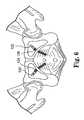
- FIG. 6illustrates exemplary placement of elements of an implant according to the invention.
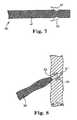
- FIG. 7illustrates an embodiment of a portion of an implant according to the invention.
- FIG. 8illustrates exemplary placement of elements of an implant according to the invention.
- FIG. 9illustrates exemplary placement of elements of an implant according to the invention.
- FIGS. 10 and 11illustrate features of an embodiment of an insertion tool according to the invention.
- FIGS. 12A , 12 B, 12 C, 12 D, and 12 Eillustrate features of embodiments of insertion tools according to the invention.
- FIG. 13A and 13Billustrate features of an embodiment of an insertion tool according to the invention.
- FIGS. 14A , 14 B, and 14 Cillustrate features of an embodiment of an insertion tool according to the invention.
- FIG. 15illustrates an embodiment of a portion of an implant according to the invention.
- FIG. 16Aillustrates an embodiment of a kit according to the invention, the kit including an implant and an insertion tool.
- FIGS. 16B and 16Cillustrate embodiments of implants according to the invention.
- FIG. 17illustrates exemplary placement of elements of an implant according to the invention.
- FIG. 18illustrates an embodiment of a portion of an implant according to the invention.
- FIG. 19illustrates exemplary placement of elements of an implant according to the invention.
- FIGS. 20A , 20 B, 20 C, and 20 Dillustrate an embodiment of a self-fixating tip according to the invention.
- FIGS. 21A and 21Billustrate an embodiment of a portion of an implant according to the invention.
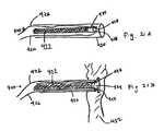
- FIGS. 22A and 22Billustrate an embodiment of a portion of an implant according to the invention.
- FIGS. 23A and 23Billustrate an embodiment of a portion of an implant according to the invention.
- a surgical implantcan be used to treat a pelvic condition, including the specific examples of implanting a support member (“implant”) to treat a condition such as vaginal vault prolapse or incontinence (male or female). Described are various features of surgical implants, surgical tools, surgical systems, surgical kits, and surgical methods, useful for installing implants.
- An implantcan be implanted in a male or a female to treat disorders such as urge incontinence, mixed incontinence, overflow incontinence, functional incontinence, fecal incontinence, or for female conditions including prolapse (e.g. vaginal or uterine), enteroceles (e.g. of the uterus), rectoceles, cystocele, and anatomic hypermobility.
- disorderssuch as urge incontinence, mixed incontinence, overflow incontinence, functional incontinence, fecal incontinence, or for female conditions including prolapse (e.g. vaginal or uterine), enteroceles (e.g. of the uterus), rectoceles, cystocele, and anatomic hypermobility.
- An implantcan include a tissue support portion (or “support portion”) that can be used to support pelvic tissue such as the urethra (which includes the bladder neck), vaginal tissue, etc. During use, the tissue support portion is typically placed in contact with and attached to tissue to be supported, such as with a suture.
- An implantcan additionally include one or more extension portions (otherwise known as “end” portions or “arms”) attached to the tissue support portion. Examples of pelvic implants are described in the following exemplary documents: U.S. patent application Ser. No. 10/834,943, filed Apr. 30, 2004; U.S. patent application Ser. No. 10/306,179, filed Nov. 27, 2002; U.S. patent application Ser. No. 11/347,063, filed Feb. 3, 2006; U.S.
- An implantmay include portions or sections that are synthetic or of biological material (e.g., porcine, cadaveric, etc.). Extension portions may be, e.g., a synthetic mesh such as a polypropylene mesh.
- the tissue support portionmay be synthetic (e.g., a polypropylene mesh) or biologic.
- implant productsthat may be similar to those useful according to the present description, include those sold commercially by American Medical Systems, Inc., of Minnetonka Minn., under the trade names Apogee® and Perigee® for use in treating pelvic prolapse (including vaginal vault prolapse, cystocele, enterocele, etc.), and Sparc®, Bioarc®, and Monarc® for treating urinary incontinence.
- Exemplary implantscan include a tissue support portion for placing in contact with tissue to be supported and one or more “extension” portions, the tissue support portion being useful to support a specific type of pelvic tissue such as the urethra, bladder, or vaginal tissue (anterior, posterior, apical, etc.).
- the tissue support portioncan be sized and shaped to contact the desired tissue when installed, e.g., as a “sling” or “hammock,” to contact and support pelvic tissue.
- a tissue support portion that is located between two or more extension or extension portionsis sometimes referred to herein as a “central support portion” or a “support portion.”
- Extension portionsare elongate pieces of material that extend from the tissue support portion and either are or can be connected to the tissue support portion, and are useful to attach to anatomical features in the pelvic region (e.g., using a self-fixating tip) to thereby provide support for the tissue support portion and the supported tissue.
- One or multiple (e.g., one, two, or four) extension portionscan extend from the tissue support portion as elongate “ends,” “arms,” or “extensions,” useful to attach to tissue in the pelvic region, such as by extending through a tissue path to an internal anchoring point as described herein.
- An example of a particular type of pelvic implantis the type that includes supportive portions including or consisting of a central support portion and either two, four, or six elongate extension portions extending from the central support portion.
- An implant that has exactly two extension portionscan be of the type useful for treating, e.g., urinary incontinence, anterior vaginal prolapse, posterior vaginal prolapse; an implant having four or six extension portions can be useful for treating combinations of these conditions.
- support portionsrefers to portions of an implant that function to support tissue after the implant has been implanted, and specifically includes extension portions and tissue support portions, and does not include optional or appurtenant features of an implant such as a sheath or self-fixating tip or other type of connector for attaching the implant to an insertion tool.
- Types of exemplary implants that can be generally useful as discussed hereincan include those previously and currently used in treating pelvic conditions, including those implants referred to as urethral “slings,” “strips,” “mesh strips,” “hammocks,” among other terms for pelvic implants.
- implants for treating incontinencee.g., urethral slings
- An exemplary urethral slingcan be an integral mesh strip with supportive portions consisting of or consisting essentially of a central support portion and two extension portions.
- Examples of urethral slings for treating male urinary incontinencecan have a widened central support portion, as discussed, for example, in Assignee's copending United States 2006/0287571 and 2006/0235262.
- Other exemplary urethral sling implantsare described in Assignee's copending United States publication numbers 2003/0171644; 2006/0195010; 2006/0195007; among others.
- implants for treating vaginal prolapsecan comprise a central support portion and from two to four to six extension portions, and may take the form of an integral piece of mesh or multiple pieces of mesh attached in a modular fashion. See, e.g., Assignee's copending United States patent 2006/028828 2006/0260618; 2005/0245787; 2006/0122457; 2005/0250977; WO/2007/016083; among others.
- Dimensions of an implantcan be as desired and useful for any particular installation procedure, treatment, patient anatomy, and to support a specific tissue or type of tissue. Exemplary dimensions can be sufficient to allow the tissue support portion to contact tissue to be supported, and to allow extension portions to extend from the tissue support portion to a desired anatomical location to allow the extension portion be secured to anatomy of the pelvic region, to support the tissue support portion.
- extension portionscan allow the extension portion to reach between a tissue support portion placed to support pelvic tissue (at an end of the extension portion connected to the tissue support portion) and a location at which the distal end of the extension portion attaches to pelvic tissue.
- a distal end of an extension portioncan include a self-fixating tip that can be attached directly to pelvic tissue such as pelvic muscle, ligament, or tendon.
- the length of the extension portiontherefore, can be in a range that allows placement of a tissue support portion as desired to support pelvic tissue, while the self-fixating tip is installed in pelvic tissue.
- a length of an extension portioncan optionally be fixed (i.e., the extension portion does not include any form of length-adjusting mechanism), as can a length of an implant spanning from opposite self-fixating tips and including extension portions and a length or segment of tissue support portion.
- Alternate embodiments of implants of the inventionmay include adjustment or tensioning mechanisms that allow a physician to alter the length of an extension portion before, during, or after implantation.
- adjustment and tensioning mechanismscan also be excluded from embodiments of implants of the invention by selecting the length of extension portions and tissue support portions, and by adjusting for tensioning or positioning of extension portions and tissue support portions based on placement of the self-fixating tip within the pelvic tissue, selected placement including selection of the point of insertion of a self-fixating tip and depth of insertion of the self-fixating tip.
- implants for treating incontinence, prolapse, or a mixture of incontinence and prolapsecan include a portion useful to support the urethra or bladder neck to address urinary incontinence.
- a urethral slingis used exclusively to support the urethra or bladder neck, and may be in the form of a mesh strip that includes a support portion implanted below the urethra or bladder neck.
- Implants for prolapse, especially anterior prolapsecan also include and anterior portion useful for supporting the urethra or bladder neck in the same fashion.
- a preferred distance between distal ends of extension portions designed to support the urethra or bladder neckcan be of a total length between distal ends (e.g., self-fixating tips) to allow the combined length of extension portions and tissue support portion to extend from a right obturator foramen to a left obturator foramen, e.g., from one obturator internus muscle to the other obturator internus muscle.
- This lengthis shown at FIG. 3C as length L 2 between self-fixating tips 182 (the length including the length of both of the self-fixating tips) of anterior extension portions of prolapse implant 180 , and at FIG. 3B as length L 2 between self-fixating tips 172 of urethral sling 170 .
- Useful lengths of extension portionsare as desired, and are exemplified elsewhere in the present description.
- a fixed-length implant or implant portione.g., as exemplified in all of FIGS. 3A , 3 B, and 3 C
- desired positioning and effecte.g., supportive force, approximation, or both
- the implant and self-fixating tipscan exhibit desirable “adjustability” or “positionability” features, without the need for a length-adjusting mechanism, as follows.
- Each self-fixating tip of an implant or anterior implant portioncan be placed within a pelvic tissue such as tissue of the obturator foramen, with properties of self-fixating tips (e.g., dimensions, pullback force, number of lateral extensions) and implant (dimensions such as length between self-fixating tips) being sufficient to allow this placement at tissue on one or both sides of the pelvic region (e.g., at opposing obturator foramen), while the tissue support portion of the implant or implant portion supports the urethra, bladder neck, vaginal tissue, etc.
- a pelvic tissuesuch as tissue of the obturator foramen
- Desired position of the implantthe amount of approximation of the supported tissue (e.g., urethra), or the amount of supportive force placed on the supported tissue, can be achieved by selecting the placement of the self-fixating tips.
- Placementcan include the position at which the self-fixating tip is inserted into tissue (the point of insertion) such as the placement of a tip within tissue of an obturator foramen relative to the entire area of the tissue of the obturator foramen (or another muscle, tendon, or ligament, etc.), and (if the pelvic tissue includes sufficient depth) can also include the depth to which the self-fixating tip is placed (penetrated) into pelvic tissue such as a muscle in the pelvic region, e.g., tissue of the obturator foramen or the obturator internus muscle.
- Each of the point of insertion, and depth of insertioncan be separately selected to result in a desired position of the implant, tension on the implant, approximation of pelvic tissue,
- tissue of the obturator foramenmeaning the obturator internus muscle, the obturator membrane, and the obturator externus muscle, may have a combined thickness in the range from about 1 to about 2 centimeters.
- An obturator internus musclemay have a thickness in the range from 0.5 to 1 centimeter.
- a self-fixating tip as described hereinmay be installed at any location (point of insertion) within tissue spanning an area of the obturator foramen, and at any depth of penetration into tissue of the obturator foramen, e.g., obturator internus muscle.
- the self-fixating tipmay be passed into the obturator internus muscle, optionally into or through the obturator membrane, and optionally into the obturator externus muscle. It may be preferred to avoid penetration of the obturator membrane.
- a self-fixating tipmay enter tissue at an angle that is perpendicular to the tissue, or at an angle that may be as much as 30 degrees, 45 degrees, or possibly more, from perpendicular. If the self-fixating tip enters at an angle non-perpendicular to the tissue, the self-fixating tip may effectively extend through an amount of tissue that is greater than the thickness of the tissue measured at a perpendicular length or depth.
- the ability to select point of insertion and depth of penetration of a self-fixating tip into a tissueis a feature of exemplary self-fixating tips and their methods of use, according to the invention, that allows a surgeon to select a location of an implant, to select an amount of tension placed on an installed implant, to place a desired amount of supportive force on a supported pelvic tissue, or combinations of these.
- embodiments of the inventionmay avoid the need for a separate length-adjustment or tensioning mechanism, and embodiments of implants according to the invention can optionally exclude any sort of length-adjustment feature or tension-adjustment feature; these features include the use of separate implant pieces that can be secured together as desired to select a length of an extension portion or length of an implant, the use of sutures to adjust a length of an extension portion or implant, adjustable mechanical fasteners, or other cinching or mechanical mechanisms that allow a surgeon to increase or decrease a length of an extension portion or implant either before, during, or after implantation.
- an extension portionmay be placed at a pelvic tissue other than the obturator foramen, such as at a different muscle, or at a ligament or tendon e.g., the arcus tendineus, sacrospinous ligament, uterosacral ligament, levator ani, etc.
- a tendon or ligamentmay have a depth less than a depth of a muscle tissue, in which case a surgeon may still select a point of entry, if not a depth of penetration, to place an implant (e.g., of fixed length) in a manner that can control location, tension, or supportive force, as stated.
- a physiciane.g., surgeon
- the surgeoninserts a first self-fixating tip in tissue of one obturator foramen, preferably in the obturator internus muscle, at a desired position (i.e., point of entry relative to the total area of the obturator foramen) and a desired depth.
- the obturator internus musclehas enough depth to allow the self-fixating tip to be placed at a variety of depths within the thickness of the muscle.
- the self-fixating tipmay be inserted to any depth at which the lateral extensions are able to resist movement back in a direction opposite of the direction of insertion, such as by penetrating a selected depth into the obturator internus muscle.
- the self-fixating tipmay be inserted in a direction perpendicular to the muscle or at an angle (resulting in a greater effective depth within which a self-fixating tip may be penetrated).
- the second self-fixating tip located on the opposite extension portion of the implantcan be inserted into tissue of the opposite obturator foramen, preferably the obturator internus muscle, and the position or tension or both of the implant below the urethra, or the amount of support, approximation, or both, of the urethra provided by the sling, etc., can be selected, controlled, or adjusted by the depth and placement of the self-fixating tips within the tissue of the opposite obturator foramen.
- these embodiments of implants of the inventioncan include a fixed length of implant material separating two opposing self-fixating tips.
- a “fixed” length of materialcan mean that the implant does not include a length-adjusting feature such as discussed elsewhere herein, but still may exhibit an amount of elasticity or other normal mechanical properties of an implant material.
- a fixed length of implant materialcan be of a single piece of material (integral), or may be of multiple pieces secured together in a manner that does not allow further adjustment of the length. For example, multiple pieces of identical mesh material may be assembled into a single implant, before implanting the assembled implant, by sewing or otherwise attaching pieces together. Pieces of different types of mesh materials may be sewn or otherwise secured together, or pieces of synthetic material may be sewn or otherwise secured to a biologic material, in a manner that does not allow for adjustment of dimensions of the assembled implant.
- the length of a urethral sling or an anterior portion of an implant, between distal ends of extension portions,can be sufficient to place opposing self-fixating tips at positions and depths of tissue of the obturator foramen, preferably without penetrating the obturator membrane, with the implant reaching between the opposing obturator foramen while supporting the urethra.
- Exemplary lengths of an implant or implant portion for extension below the urethra, between opposing obturator foramen, from distal end to distal end of the extensions while laying flatcan be in the range from about 6 to 15 centimeters, e.g., from 7 to 10 centimeters or from 8 to 9 centimeters or about 8.5 centimeters. (Lengths L 1 and L 2 of FIGS. 3B and 3C can be within these ranges.)
- the lengthsare for male and female urethral slings, and are for anterior portions of implants for treating female prolapse or combined female prolapse and incontinence, which include an anterior portion that has a length between ends of anterior extensions portions within these same ranges.
- a width of the extension portioncan be as desired, such as within the range from about 1 to 1.5 centimeters.
- An extension portion of an implant of the inventioncan include a self-fixating tip at an end of the extension portion that is distal from a tissue support portion.
- the self-fixating tipin general can be a structure connected to a distal end of an extension portion and that can be implanted into tissue in a manner that will maintain the position of the self-fixating tip and the attached implant.
- Exemplary self-fixating tipscan also be designed to engage an end of an insertion tool (e.g., elongate needle, elongate tube, etc.) so the insertion tool can be used to push the self-fixating tip through tissue for implantation.
- the self-fixating tipmay engage the insertion tool at an internal channel of the self-fixating tip, at an external location such as at the base, or at a lateral extension, as desired.
- a self-fixating tipcan be made out of any useful material, generally including materials that can be molded or formed to a desired structure and connected to or attached to an end of an extension portion of an implant.
- Useful materialscan include plastics such as polyethylene, polypropylene, and other thermoplastic or thermoformable materials, as well as metals, ceramics, and other types of biocompatible and optionally bioabsorbable or bioresorbable materials.
- Exemplary bioabsorbable materialsinclude, e.g., polyglycolic acid (PGA), polylactide (PLA), copolymers of PGA and PLA,
- a self-fixating tipalso, preferably, includes one or more lateral extensions that can increase the force required to remove the self-fixating tip from tissue after insertion into the tissue, i.e. the “pullout force.” At the same time, the lateral extensions can be designed to exhibit a reduced or relatively low “insertion force,” which is the amount of force used to insert the self-fixating tip into tissue.
- the self-fixating tipis designed to be essentially permanently placed upon insertion into tissue, with the single exception that if absolutely necessary to provide desired placement of the self-fixating tip or an attached implant, the self-fixating tip may be removed by a surgeon during an implantation procedure.
- the self-fixating tip, and all components of the self-fixating tipcan be of combined form and dimensions to result in these functional features.
- Factors that can be balanced in designing a self-fixating tip as describedinclude insertion force and pullout force, the insertion force being preferably reduced or minimized while a pullout force allows removal of the self-fixating tip only when desired by a surgeon during an implantation procedure.
- the self-fixating tip designcan attempt to minimize the amount of potential trauma caused to tissue by inserting or, when necessary, removing, a self-fixating tip. A desired combination of these factors can be achieved by selecting size, shape, and other structural features of the self-fixating tip and the elements of the self-fixating tip such as the base and lateral extensions.
- a self-fixating tipcan have from one to a large number of lateral extensions, but it has been found that a self-fixating tip can function well with a small number of fixed lateral extensions such as two or four lateral extensions.
- embodiments of self-fixating tipsinclude lateral extensions located at the same position along the longitudinal dimension (length) of the base between the proximal base end and the distal base end.
- a self-fixating tip that includes exactly two lateral extensionscan be located opposite of each other along a length of a base, to provide desired insertion and pullout forces, especially by implanting the two lateral extensions to be oriented in fibrous tissue with the direction of the lateral extensions being not parallel to the tissue fibers, for example being perpendicular to the fibers (or “across the grain”). Also, a relatively low number of lateral extensions, such as two, can desirably reduce the amount of trauma when, as may become necessary at the discretion of a surgeon during implantation, a self-fixating tip must be withdrawn from tissue after placement.
- a self-fixating tipcan be sizes of the base, lateral extensions, or both, to allow the self-fixating tip to be inserted into tissue at a selected depth.
- a lateral extension that will be placed into muscle tissuecan have a length dimension (measured along a longitudinal axis of the base) that allows the self-fixating tip to be inserted into the tissue at any selected depth along the thickness of the tissue. This can mean that the length dimension of the lateral extension is shorter than the total depth of the muscle tissue.
- a base of a self-fixating tipcan be of any desired size, shape, and dimension (e.g., length, diameter, width).
- a diameter of a cylindrical basecan be any useful size, for example from about 2 to about 5 millimeters. The diameter may be uniform along the length of the base, between a base proximal end and a base distal end, or a diameter may change. For example, a diameter of a base may be greater at a proximal end, and taper to a reduced diameter at a distal end, to optionally reduce insertion force or increase pullout force.
- the diameter or diameter profile of a basemay preferably be relatively small, e.g., minimized, to reduce trauma to tissue when implanted or removed. The diameter can also be sufficient to allow placement of a desired number of lateral extensions around the perimeter of the base.
- Exemplary self-fixating tips discussed hereininclude a cylindrical base or tapered cylindrical base, with a hollow or solid interior.
- Other shapes for a basemay also be useful, such as blocks having square or rectangular forms when viewed in cross section along a longitudinal axis extending from a proximal base end to a distal base end.
- dimensions of a square or rectangular cross sectioncan be of a range similar to the diameter of a cylindrical base, such as from about 2 to about 5 millimeters in either dimension when viewed in cross section.
- lengths(measured from the proximal base end to the distal base end along a longitudinal axis of the self-fixating tip) in the range from 0.4 to 1.0 centimeter, e.g., from 0.4 to 0.8 centimeters, or from 0.4 to 0.7 centimeters, have been found to be useful.
- the relatively short lengthcan allow the self-fixating tip to be inserted into the muscle tissue a desired depth, i.e., over a range of depths, optionally without penetrating the obturator membrane; the self-fixating tip can be of a length dimension that is less than the thickness of the muscle, so the self-fixating tip can be inserted a desired distance into the muscle.
- a self-fixating tipcan have structure that includes a base having a proximal base end and a distal base end.
- the proximal base endcan be connected (directly or indirectly, such as by a connective suture) to a distal end of an extension portion of an implant.
- the baseextends from the proximal base end to the distal base end and can optionally include an internal channel extending from the proximal base end at least partially along a length of the base toward the distal base end.
- the optional internal channelcan be designed to interact with (i.e., engage) a distal end of an insertion tool to allow the insertion tool to be used to place the self-fixating tip at a location within pelvic tissue of the patient.
- Alternate embodiments of self-fixating tipsdo not require and can exclude an internal channel for engaging an insertion tool.
- These alternate embodimentsmay be solid, with no internal channel, and may engage an insertion tool, if desired, by any alternate form of engagement, such as, for example, by use of an insertion tool that contacts the self-fixating tip at an external location such as by grasping the base (on a side or at the face of the proximal base end) or by contacting a lateral extension.
- Embodiments of self-fixating tipsalso include one or more lateral extension extending laterally (e.g., radially) from the base, such as from a location between the proximal end and the distal end, from a location at the distal base end, or from a location at the proximal base end.
- Exemplary lateral extensionscan be rigid or “fixed” relative to the base so the lateral extension does not substantially move or deflect during or after implantation.
- a fixed lateral extensioncan be a lateral extension that is not substantially moveable relative to the base in a manner that certain types of known soft tissue anchor extensions are moveable, for instance between a non-deployed or non-extended position that places an extension against the base to allow insertion of the anchor into tissue with a reduced size or shape profile, and a deployed or extended position that places the extension away from the base to engage tissue and prevent movement of the self-fixating tip in a direction opposite of the direction of insertion.
- Alternate embodiments of lateral extensionscan be moveable or deflectable, if desired, such as to allow a reduced insertion force by use of lateral extensions that deflect backward when a self-fixating tip is being pushed through tissue.
- a lateral extensioncan have a three-dimensional form that results in a balance of the performance factors discussed herein, including insertion force, pullout force, and reduced trauma caused to tissue during insertion or in the event of a need to remove the self-fixating tip during an implantation procedure.
- a lateral extensioncan include a three-dimensional form referred to as an extension body defined as the lateral extension material between a leading edge, a trailing edge, and a boundary at which the lateral extension connects to a base; away from the boundary of the lateral extension and the base, the far lateral edge of a lateral extension may include a point of connection of the trailing edge and the leading edge, or another segment or connection may connect the leading edge with the trailing edge away from their respective connections to the base.
- the “leading edge”means the boundary of the lateral extension on the side of the lateral extension toward the base distal end, which is also the edge that leads the lateral extension body and contacts tissue first as the self-fixating tip is inserted into tissue by pushing.
- the “trailing edge”means the boundary of the lateral extension on the side of the lateral extension toward the base proximal end, which is also the edge that trails behind the lateral extension body and passes through or contacts tissue last when the self-fixating tip is inserted into tissue by pushing.
- the lateral extension bodycan exhibit a thickness or thickness profile as desired, such as a uniform thickness or a varied thickness across the extended area of the body.
- implantsmay include a leading edge of a low profile, e.g., reduced thickness or even sharpened, to allow for reduced insertion force.
- the thickness of the lateral extension bodycan reduce gradually or taper from a central portion of the body (away from edges) in the direction of a leading edge.
- a leading edgebeing of a reduced thickness to reduce insertion force, may optionally in addition exhibit a form that extends in a direction back toward the trailing edge, i.e., a “swept-back” leading edge, to further reduce insertion force.
- the shape of the leading edgemay be linear or arcuate, and if arcuate may be convex or concave.
- the leading edgemay take an arcuate convex path that sweeps back to meet the trailing edge at a single lateral extension point away from the base. E.g., see the exemplary self-fixating tip illustrated at FIG. 1 .
- the direction and shape of the trailing edge of a lateral extensionmay be linear or arcuate, and if arcuate may be convex or concave relative to the lateral extension body.
- a trailing edgecan be as desired, such as arcuate, straight, convex, flat, linear, rounded, tapered, sharp, blunt, etc.
- a trailing edgecan exhibit a thickness (a thickness dimension is illustrated, e.g., at FIG. 2 ) to produce increased pullout force, yet that does not result in undue trauma in the event that a self-fixating tip must be removed from tissue after insertion.
- a trailing edgecan exhibit an area that includes a width (w, the distance the trailing edge extends laterally away from the base) and a thickness (t, the distance perpendicular to the width and the longitudinal axis of the self-fixating tip).
- An exemplary width (w, in FIG. 2 ) of the trailing edgecan be, e.g., in the range from 0.5 to 3 millimeters.
- An exemplary thickness at a trailing edgemay be the same as a thickness at an interior or central portion of the lateral extension (away from the leading and trailing edges), or a thickness at a trailing edge may be a maximum thickness of the entire lateral extension, meaning for example that the thickness increases from a narrow thickness at the leading edge and widens gradually to a maximum thickness at the trailing edge.
- a thickness of a trailing edgecan be, e.g., in the range from 0.2 to 2 millimeters, e.g., from 0.5 to 1.5 millimeters.
- a surface area of a trailing edgemay be, e.g., from the range from 0.25 to 5 square millimeters, e.g., from 0.5 to 4, or from 1 to 3 square millimeters.
- the surface area of the trailing edgemay be concave, convex, rounded, tapered (symmetrically or toward one or the other surfaces of the lateral extension), etc.
- a flat surfacemay be preferred, to provide increased or maximum pullout force for preventing removal of the self-fixating tip after implantation.
- a lateral extensioncan also include a third dimension that can be referred to as a “length” dimension (shown as “L” at FIG. 1 ).
- a lengthcan be measured at a location where the lateral extension meets or extends from the base. This length dimension can become smaller as the lateral extension extends from the base.
- An exemplary length of a lateral extension at the location of the lateral extension meeting the basecan be, e.g., from 0.5 to 5 millimeters, such as from 1 to 4 millimeters or from 1.5 to 3.5 millimeters.
- an exemplary length of a lateral extensioncan be a length that is less than the total thickness of obturator foramen tissue (i.e., the combined thickness of obturator internus muscle, obturator membrane, and obturator externus muscle); a length of a lateral extension intended to be inserted into the obturator internus muscle can be a length that is a portion of the thickness of the obturator internus, e.g., less than 1 centimeter, such as less than 0.5 centimeter.
- a self-fixating tipcan include multiple lateral extensions at multiple locations, either at different positions along a length of a base, at different locations around a perimeter of a base, or both.
- a self-fixating tipmay preferably include all lateral extensions originating from the same position along a length of a base, e.g., a single set of lateral extensions can be arranged around a perimeter of a base, each extending in a different direction but from the same portion of length between the proximal base end and the distal base end. See, e.g., FIGS. 1 , 3 A, 3 B, 3 C, 4 , and 5 .
- a self-fixating tipcan be connected to an extension portion of an implant in any fashion, directly by any attachment mechanism, or indirectly such as through an attachment structure such as a suture.
- a connectioncan be based on a mechanical structure, by adhesive, by a connecting suture, or by an integral connection such as by injection molding or “insert” molding (also, “overmolding”) as described U.S. Publication No. 2006-0260618-A1, incorporated herein by reference.
- a thermoplastic or thermosetting polymer materialcan be insert molded or injection molded at an end of a mesh extension portion of an implant, e.g., directly to the mesh.
- a molded polymercan form a self-fixating tip at an end of an extension portion.
- the self-fixating tipcan be as described herein, for example, including lateral extensions and an internal channel.
- FIG. 1shows self-fixating tip 10 , including base 12 (for attachment to an implant extension end), proximal base end 14 , distal base end 16 , internal channel 18 , and two lateral extensions 20 located on outer surfaces and on opposite sides of base 12 .
- Tip 10can be prepared from a biocompatible material, preferably a biocompatible material such as a biocompatible polymer, which may optionally be bioresorbable or bioabsorbable.
- Exemplary self-fixating tip 10 as illustratedincludes internal channel 18 (optional according to the invention) which is an opening within base 12 extending from proximal end 14 toward distal end 16 along at least a portion of the total longitudinal length of base 12 .
- Internal channel 18is capable of receiving a distal end of an elongate needle of an insertion tool to allow tip 10 to be pushed into position within pelvic tissue during an implant installation procedure.
- Lateral extensions 20include leading edge 24 and trailing edge 26 .
- Leading edge 24originates at base 12 and extends away from base 12 along an arcuate pathway sweeping back toward proximal base end 14 , meeting trailing edge 26 at point 28 .
- Leading edge 24can preferably include a reduced thickness or a sharp or sharpened edge.
- Trailing edge 26is shown to be relatively straight but could alternately be arcuate, concave, or convex. Trailing edge 26 has a flat surface area. Trailing edge 26 is also shown to sweep slightly back in a proximal direction, although it could alternately extend straight away from (i.e. perpendicular to) base 12 or extend away from base 12 in a direction that includes a forward component, i.e., a directional component in the direction of distal base end 16 .
- self-fixating tip 10is viewed in a direction looking at proximal base end (surface) 14 along a longitudinal axis of base 12 .
- surface areas of lateral extensions 20are shown as flat surfaces of approximately the area of thickness (t) by width (w).
- interior surface 22 of internal channel 18 of base 12is also visible in FIG. 2 .
- Surface 22functions to orient self-fixating tip 10 in a desired rotational orientation relative to a distal end of a needle of an insertion tool; the distal end of the needle can be provided with a flat surface that is complementary to surface 22 .
- surface 22does not need to be a flat surface but could be any other type of surface or protrusion such as a rounded surface, angled surface, key structure, edge, or other feature that can orient a self-fixating tip rotationally relative to a distal end of an insertion needle.
- An insertion toolcan be used to install the implant.
- Various types of insertion toolsare known, and these types of tools and modifications thereof can be used according to this description to install an implant.
- useful toolsinclude those types of tools that generally includes a thin elongate needle that attaches to a handle; a handle attached to one end (a proximal end) of the needle; and a distal end of the needle adapted to engage a self-fixating tip that allows the needle to push the self-fixating through a tissue passage and insert the self-fixating tip within tissue of the pelvic region.
- This class of toolcan be used with a self-fixating tip that includes an internal channel designed to be engaged by a distal end of an insertion tool.
- insertion toolsmay engage a self-fixating tip in a manner that does not involve an internal channel of a self-fixating tip.
- These alternate insertion toolsmay for example contact or grasp a proximal base end of a self-fixating tip in the absence of an internal channel extending from the proximal base end toward the distal base end, such as by grasping an external surface of the base.
- An alternate insertion toolmay contact or grasp a side of the base, a lateral extension, or any other portion of the self-fixating tip or base, in a way that allows the insertion tool to hold the self-fixating tip and insert the self-fixating tip at a desired location within tissue of the pelvic region.
- Exemplary insertion tools for treatment of incontinence and vaginal prolapseare described, e.g., in U.S. patent application Ser. Nos. 10/834,943, 10/306,179; 11/347,553; 11/398,368; 10/840,646; PCT application number 2006/028828; and PCT application number 2006/0260618; among others.
- Tools described in those patent documentsare designed for placement of an implant in a pelvic region for the treatment of prolapse, male or female incontinence, etc.
- the tools of the above-referenced patent documentsmay be curved in two or three dimensions, and may include, for example, a helical portion in three dimensions for placing an extension portion of an implant through a tissue path that passes from a region of the urethra, through an obturator foramen, to an external incision in the groin or inner thigh area.
- Other described insertion toolsinclude a two-dimensional elongate needle that allows a user to place an extension portion of an implant through an external incision in the perirectal or coccyx region of the lower back and buttock area.
- Exemplary insertion tools for use according to the inventioncan be similar to or can include features of tools described in the above-referenced patent documents.
- those insertion toolsmay be modified to allow the insertion tool to be used to place a self-fixating tip at tissue within the pelvic region through a tissue path that does not extend to an external incision.
- the insertion toolcan be designed, shaped, and sized, to include an elongate inserter or needle that may be straight or that may be curved in two or three dimensions, that can be inserted through a vaginal incision (for female anatomy) or through a perineal incision (for male anatomy), and to extend from that incision to a pelvic tissue location for placement of a self-fixating tip.
- exemplary insertion tools for use according to embodiments of presently described methodscan be sized and shaped to place a self-fixating tip at an internal location of the pelvic region, and do not need to be sufficiently long to extend from a vaginal or perirectal incision to an external incision. The length can be only sufficient to reach from a vaginal or perirectal incision to an obturator foramen, for example.
- the lengthmay be only sufficient to reach from a vaginal or perirectal incision to a different muscle or tissue, such as a levator ani, coccygeous muscle, iliococcygeous muscle, arcus tendineus, sacrospinous ligament, etc., to place a self-fixating tip at one of those tissues.
- a self-fixating tipmay be placed into pelvic tissue that is a fibrous tissue such as muscle, ligament, or tendon, with specific examples including the arcus tendineus, the obturator internus muscle, the levator ani, and the sacrospinous ligament.
- an elongate portione.g., elongate inserter, elongate needle, etc.
- an insertion toolcan include an engagement surface for contacting a self-fixating tip, the engagement surface being in the form of any one of an internal channel or an external surface, channel, extension, or other structure.
- a complementary surface of a self-fixating tipcan be designed to place tip at an orientation so that lateral extensions of a self-fixating tip (i.e., the extended or “width” direction of lateral extensions) are implanted within the fibrous tissue at an orientation that places the lateral extensions in a direction that is non-parallel to the fibers of the fibrous tissue, e.g., that is at an angle of at least 45 degrees to the direction of the fibers, such as at an angle in the range from 50 to 130 degrees, or from 60 to 120 degrees, or from 70 to 110 degrees, preferably perpendicular to the fibers.
- placing lateral extensions in such a non-parallel orientationcan increase pullout force.
- exemplary self-fixating tipscan include only two lateral extensions located on opposite sides of a base.
- an insertion tool and self-fixating tipcan be designed to orient two lateral extensions of a self-fixating tip at an angle perpendicular to fibers of the obturator internus muscle when the needle and tip are inserted through a transvaginal incision and a tissue path leading to the obturator internus muscle.
- an insertion toolthat includes a curve (in two dimensions) that allows the distal end to be located at the obturator internus muscle when the needle is inserted through a vaginal incision, and that orients lateral extensions relatively perpendicular to (e.g., at an angle in the range from 75 to 105 degrees, such as from 80 to 100 degrees) a plane defined by the curve, will also cause the lateral extensions to enter the obturator internus muscle at an orientation that is substantially perpendicular to the fibers of the muscle.
- Orientation of a self-fixating tip and lateral extensions relative to a needle (and tissue fibers)can be controlled using an engagement between the self-fixating tip and the needle that maintains the radial orientation of the self-fixating tip relative to the longitudinal axis of the distal end of the needle.
- the orientationmay be maintained by any desired method, such as by one or more engaging surfaces of an internal channel of a self-fixating tip that align with one or more surfaces of a distal end of a needle.
- another surface of a self-fixating tipsuch as a surface of the base on the proximal base end, on the outer surface of the base, or a lateral extension, may provide the desired orientation.
- the surfacescan be complementary, and may include flat, curved, circular, semi-circular, rounded, “keyed,” or otherwise opposing surfaces that allow a surface of self-fixating tip to provide desired engagement with the insertion tool.
- an internal channel of a self-fixating tipcan fit over a length of a distal end of a needle of an insertion tool with a single or alternate fixed radial orientations relative to an axis of an insertion tool.
- an example of a combination of insertion tool and self-fixating tipcan include an elongate curved needle, hollow tube, or other “elongate inserter,” curved in two dimensions, and a self-fixating tip; the distal end of the needle, tube, or inserter, and the self-fixating tip, include complementary engaging surfaces that can cause the self-fixating tip to be oriented at the distal end of the needle, tube, or inserter so that lateral extensions are oriented to be perpendicular (90 degrees, or more broadly, at an angle in the range from 80 to 100 degrees) to a plane defined by the two-dimensional curve.
- the elongate inserter(e.g., needle or tube) may be of a length that allows the end of the inserter to be inserted through a perineal incision or a vaginal incision and to reach an obturator foramen, levator ani, sacrospinous ligament, or arcus tendineus.
- the insertion toolcan be useful for placing a self-fixating tip at tissue of the obturator foramen, levator ani, sacrospinous ligament, or arcus tendineus, or other tissue of the pelvic region, preferably with lateral extensions being oriented non-parallel to fibers of a fibrous tissue.
- Implants as describedcan be useful for treating male and female conditions of the pelvic area.
- specific pelvic floor disordersare fecal and urinary incontinence such as stress urinary incontinence (SUI) in both men and women, and prolapse conditions in women.
- the implantcan be designed for a specific application with a size, shape, and number of extension portions designed to support a specific type of pelvic tissue.
- an implantcan include one or multiple self-fixating tips at one or multiple ends of extension portions, and an implantation method can include placing the self-fixating tip or tips within tissue in the pelvic region to support the implant as the implant supports a type of pelvic tissue.
- the tissuecan be a fibrous tissue such as a muscle (e.g., of the obturator foramen, obturator internus, obturator externus, levator ani, coccygeous, iliococcygeous), ligament (e.g., sacrospinous ligament), tendon (arcus tendineus), etc.
- a self-fixating tipcan be oriented in a fibrous tissue to cause a major dimension (referred to herein as the “width”) of a lateral extension to be oriented in a direction that is not parallel to the direction of the fibers.
- the self-fixating tipcan be inserted at a desired point of entry relative to the total area of the tissue, and, for tissues of sufficient thickness or depth, the self-fixating tip can be inserted to a selected depth.
- a single example of a method according to the inventionis a method of treating urinary incontinence by surgical implantation of a urethral sling (e.g., a single, integral, optionally uniform, woven polymeric mesh strip, with two self-fixating tips, one on each end) through a vaginal (for female anatomy) or perineal (for male anatomy) incision, along a tissue path that extends from a region of the urethra to the obturator foramen.
- a urethral slinge.g., a single, integral, optionally uniform, woven polymeric mesh strip, with two self-fixating tips, one on each end
- vaginalfor female anatomy
- perinealfor male anatomy
- An elongate urethral slingis attached at tissue of the opposing obturator foramen by self-fixating tips at opposing distal ends of the urethral sling, with the sling positioned to pass below the urethra to support the urethra.
- An exemplary method of installing a male urethral slingcan include a step of creating a perineal (e.g., medial) incision at the external male perineum and creating opposing tissue paths from the medial incision, below the urethra, to the patient's left and right obturator foramen, and installing a urethral sling that includes extension portions with self-fixating tips for placement at tissue of the obturator foramen, e.g., the obturator internus muscle.
- the self-fixating tipcan include lateral extensions (e.g., two, of the same size and shape and form, extending in opposite directions from opposite sides of the base).
- lateral extensionsWhen installed, lateral extensions can be oriented in a direction that is non-parallel to, e.g., substantially perpendicular to, fibers of the obturator internus muscle.
- the urethral slingmay be placed using one or more insertion tools as described, by installing extension portions of the sling between the incision and the obturator foramen, with the middle (support) portion of the sling positioned below the urethra.
- the extension portionsmay be pushed through the tissue path at the lead of an insertion tool that engages the self-fixating tip and maintains the self-fixating tip in an orientation to enter the obturator internus muscle with lateral extensions non-parallel to the muscle fibers.
- the fixed orientationis maintained, and rotation is presented, also, during insertion and passage through tissue.
- the tissue support portion (central portion) of the urethral slingmay be placed as desired to support the urethra, optionally with approximation, compression, or a combination of approximation and compression. Adjustment of the implant can be performed based on the location (point of entry) and depth of insertion of the self-fixating tips at tissue of the opposing obturator foramen.
- the slingmay be placed below the bulbospongiosus muscle or below the corpus spongiosum, as desired.
- the slingmay optionally include a widened central support portion that is placed to contact the corpus spongiosum, and the support portion and sling are used to approximate the urethra to improve continence, e.g., without the need for compression of the urethra. See, e.g., U.S. patent application Ser. Nos. 11/347,553 and 11/347,047.
- FIG. 3AAn embodiment of a kit according to the invention, including an insertion tool and an implant, is shown at FIG. 3A .
- Incontinence sling 100can be installed to help maintain continence by supporting the urethra during times of increased abdominal pressure.
- the present inventionalso includes methods of implanting the sling 100 .
- Sling 100can be implanted through a single incision in the vaginal wall for females, or perineal floor for males, and attached to (e.g., anchored to) the obturator internus muscle on either side of the urethra.
- sling 100may be anchored at other locations besides the obturator internus muscle, such as, for example, the obturator membrane or the obturator externus muscle.
- a preferred methodmay be to implant sling 100 having self-fixating tips at opposing extension portions, without penetrating the obturator membrane.
- the present disclosuremay focus on the obturator internus anchoring location, with the understanding that other anchoring locations may be selected by those of skill in the art.
- sling 100may include a first anchor (i.e., “self-fixating tip”) 120 , a second anchor 122 , a first anchoring arm 124 , a second anchoring arm 126 , and a sling body (“central support portion” or “tissue support portion” 128 ).
- sling body 128may be suspended between first anchoring arm 124 and second anchoring arm 126 and may be operably attached to a first end of each 124 A, 126 A.
- Second end 124 B, 126 B of each anchoring arm 124 , 126is attached to corresponding anchor 120 , 122 .
- the overall dimensions of the sling 100may be 6-15 cm in length, in the range from 6 to 10, 8 to 10, 10 to 15, 10 to 12, or 12 to 15 centimeters in length, and 1-2 cm, more preferably 1-1.5 cm, in width (at the arms).
- the total length dimension between anchorsshould be at least sufficient to extend from an obturator internus muscle on one side of the urethra and into an obturator internus muscle on the opposite side of the urethra.
- Self-fixating tips 120 and 122include a base, optional internal channel (not shown), and four lateral extensions, and the design is to allow self-fixating tips 120 and 122 to be implanted securely within tissue of the obturator foramen.
- FIG. 3Aincludes a perspective view of one implant embodiment of the present invention, and the invention is not limited to the particular embodiment shown. It is understood that a large number of different sizes, shapes, and dimensions of implant (e.g., slings) will be suitable according to different embodiments of methods and implants described herein.
- the sling body 128 and anchoring arms 124 , 126are all substantially one piece (i.e., “integrated”) and may be of uniform width and thickness. In such an embodiment the sling may appear as one continuous ribbon or tape.
- sling 110may be an assembly of two or more pieces, e.g., different pieces of mesh or combinations of mesh and a biologic material.
- Sling body 128may be made by being woven, knitted, sprayed, or punched from a blank.
- sling body 128may include one or more woven, knitted, or inter-linked filaments or fibers that form multiple fiber junctions.
- the fiber junctionsmay be formed via weaving, knitting, braiding, or through other techniques, including combinations thereof.
- the size of the resultant openings or pores of the meshmay be sufficient to allow tissue in-growth and fixation within surrounding tissue.
- the material used to make the sling body 128 , arms 124 and 126 , and anchors 120 and 122may include a variety of different plastics or other materials that are strong but conducive to being used in the body, such as, but not limited to, polypropylene, cellulose, polyvinyl, silicone, polytetrafluoroethylene, polygalactin, Silastic, carbon-fiber, polyethylene, nylon, polyester (e.g. dacron) PLLA, acetols, EPTFE and PGA.
- plastics or other materialsthat are strong but conducive to being used in the body, such as, but not limited to, polypropylene, cellulose, polyvinyl, silicone, polytetrafluoroethylene, polygalactin, Silastic, carbon-fiber, polyethylene, nylon, polyester (e.g. dacron) PLLA, acetols, EPTFE and PGA.
- Sling body 128 , arms 124 and 126 , and anchors 120 and 122each may independently be any of resorbable, absorbable or non-absorbable; optionally, some portions may be absorbable and other portions may be non-absorbable.
- the material used to make the sling body 128may include a non-synthetic material or a synthetic and non-synthetic blend of materials.
- Some example of commercially available materialsmay include MarleXTM (polypropylene) available from Bard of Covington, R.I., ProleneTM (polypropylene) and Mersilene (polyethylene terephthalate) Hernia Mesh available from Ethicon, of New Jersey, Gore-TeXTM (expanded polytetrafluoroethylene) available from W. L. Gore and associates, Phoenix, Ariz., and the polypropylene sling available in the SPARCTM sling system, available from American Medical Systems, Inc. of Minnetonka, Minn.
- Commercial examples of absorbable materialsinclude DexonTM (polyglycolic acid) available from Davis and Geck of Danbury, Conn., and VicrylTM available from Ethicon.
- First and second arms 124 , 126may likewise be made by weaving, knitting or in any of the other ways previously discussed in reference to sling body 128 .
- First and second arms 124 , 126may be made of the same or different material as sling body 128 and may include the same or different physical characteristics, such as, for example, reabsorbability.
- first and second anchoring arms 124 , 126may be a weave that results in a stronger or denser material than the weave used to make the sling body 128 so as to support more weight over a given surface area.
- the arms 124 , 126may not be woven.
- sling body 128 and the first and second arms 124 , 126may be made of one continuous weave structure of the same or different weave densities.
- FIGS. 3B and 3Cillustrate alternate embodiments of implants of the invention.
- FIG. 3Bshows urethral sling (mesh strip) 170 for supporting a male or female urethra by placement of self-fixating tips 172 at tissue of the obturator foramen.
- Length L 1can be, e.g., about 8.5 centimeters.
- FIG. 3Cillustrates implant 180 for treating vaginal prolapse.
- Self-fixating tips 182are at ends of anterior extension portions 183 , which are each connected at their opposite ends to an anterior portion of tissue support portion 184 .
- Posterior or central extension portions 185are connected at one end to central portion of support portion 184 , and include self-fixating tips 186 at the opposite ends.
- Self-fixating tips 186may be placed at tissue of the central or posterior pelvic region such as a muscle, tendon, or ligament, e.g., a muscle of the obturator foramen, levator ani, coccygeous, iliococcygeous; sacrospinous ligament; arcus tendineus.
- central portion 184can be a biologic material, but could alternately be a mesh or other synthetic material.
- Extension portions 183 and 185are illustrated to be of synthetic mesh.
- first and second anchors 120 , 122 of an implantcan be substantially identical, and, as illustrated, can be described with reference to anchor 120 .
- Anchors 120 , 122may also be known as anchor members, fixation members, self-fixating tips, or fasteners.
- anchor 120may include a body (or “base”) 130 with a first (distal) end 132 and a second (proximal) end 134 .
- a number of fixation wings (or “lateral extensions”) 136may be attached to body 130 at some point or along a length between first end 132 and second end 134 .
- anchor 120includes four fixation wings 136 spaced evenly about a perimeter of body 130 .
- anchor 120may include a greater or lesser number of fixation wings 136 , positioned in any desired pattern around the body 130 .
- Fixation wings 136may also be referred to as or may include barbs, extensions, fins, tines, spikes, teeth, or pins.
- Fixation wings 136may be as described elsewhere in the present description, and may according to certain embodiments be in the form of relatively thin (a thickness in the range of millimeters or less) wing-type structures that extend generally perpendicularly from the surface of body 130 .
- Fixation wings 136may extend away from body 130 to form a smoothly angled surface 138 .
- Surface (or “edge”) 138may extend further from body 130 when traveling from first end 132 toward second end 134 in a continuous or other angular, curved, arcuate, concave, convex, or other pattern.
- the form of surface (or “edge”) 138can be one that allows for anchor 120 to be implanted through tissue in an implantation direction with reduced or minimal damage to the tissue, and reduced or minimal insertion force.
- Fixation wings 136may further include tip 140 .
- Tip 140may be a barbed-like structure at the tail end of sloping surface 138 . Tip 140 may allow for anchor 120 to resist being withdrawn from a desired anchoring position. Tip 140 may form a pointed tip 140 or may form a more rounded tip. In either case, tip 140 provides anchor 120 with a structure that helps to bind anchor 120 in a desired position in a pelvic tissue. As will be further discussed, anchors such as anchors 120 , 122 are designed for anchoring an implant to tissue rather than bone.
- fixation wing 136may take other forms such as a barb, spike, (optionally fixed) etc., that can effectuate the implantation of anchors 120 , 122 in the desired location.
- body 130 of anchor 120may include barbs and spikes in addition to the fixation wing 136 .
- Fixation wings 136 of FIGS. 4 and 5are fixed, meaning not substantially moveable between different positions.
- anchorssuch as anchors 120
- fixation wingsor “lateral extensions” 136 that are moveable, e.g., that are extended or deployed to an extended position from body 130 after anchor 120 is in the desired position, or that will otherwise move or deflect during or after insertion into tissue.
- Embodiments of implants such as a sling 100may further include a protective sleeve 150 , as shown in FIG. 3A .
- Sleeve 150may be a protective sheath that is placed over sling 100 or an extension portion ( 126 ) before implantation, to assist with implantation.
- Some slings 100may be sufficiently robust to be inserted without a protective sleeve 150 .
- sleeve 150may provide support for the implant, protection for the tissue, or both.
- Sleeve 150 covering mesh of sling 100may be designed to minimize risk of contamination and to reduce abrasive “sliding” of sling 100 through tissue of a patient.
- Sleeve 150may be particularly desirable when sling 100 is elastic, as sleeve 150 assists in introducing sling 100 within tissue and avoids damage to material of sling 100 . After sling 100 is implanted, sleeve 150 is removed and discarded.
- protective sleeve 150is constructed of a material that allows for visual examination of sling 100 and that affords convenient passage of sling 100 through tissue of the patient.
- sleeve 150is made of polyethylene.
- Other materialsincluding, without limitation, polypropylene, nylon, polyester, or Teflon may also be used to construct sleeve 150 .
- Sleeve 150should also conveniently separate from sling 100 after sling 100 is implanted, without materially changing the position or shape of sling 100 .
- sleeve 150may comprise two elongate, separable sections, that substantially form one continuous covering over anchor arms 124 , 126 and optionally body 128 and anchors 120 , 122 .
- portions of two sleeves 150 on opposite armsmay detachably and telescopically overlap near the middle portion of the sling.
- sleeve 150may be slit or perforated or otherwise breakable (e.g. longitudinally or perpendicular to the longitudinal axis) to afford convenient separation of the separable sections into separated pieces that can be removed from a patient after implantation of an anchor.
- a material that forms any portion of a sling 100may include one or more substances incorporated into the material or coated onto the material of the sling.
- substancesmay include, without limitation, drugs, hormones, antibiotics, antimicrobial substances, dyes, silicone elastomers, polyurethanes, radio plaque filaments or substances, position or length indicators, antibacterial substances, chemicals or agents, including any combinations thereof.
- a substance or materialmay be used to enhance treatment effects, reduce potential sling rejection by the body, reduce the chances of tissue erosion, allow or enhance visualization or location monitoring, indicate proper sling orientation, resist infection, or other provide other desired, useful, or advantageous effects.
- an implant such as sling 100may be introduced using an “inside-out” approach to place the implant below the urethra with ends at tissue of the two opposite obturator foramen, through an incision at the vagina or perineum.
- the precise, final location of an implante.g., sling 100
- an implant such as sling 100may be placed in close proximity to, but not in contact with, a mid portion of the urethra to treat incontinence.
- an implant such as sling 100may be placed near the bladder neck.
- the present inventionis particularly suitable for placing a sling 100 or an anterior portion of a larger implant that may also treat prolapse, in a therapeutically effective position for treating any one or a combination of pelvic conditions.
- a patientmay be first placed under local, spinal, or general anesthesia.
- a female condition of incontinencee.g., a small, medial, transvaginal incision for treating female urinary incontinence
- a perineal incisionmay be made instead.
- the incisionshould be large enough for the surgeon to place sling 100 through the incision using selected instruments.
- a desired amount of tissuemay optionally be dissected on each side, for placement of sling 100 .
- the tissuemay be dissected approximately 1-2 centimeters in each direction away from the urethra and toward opposing locations for anchors (or “self-fixating tips”) 120 (e.g., at tissue of the obturator foramen).
- the dissection of tissuemay be as much or as little as desired, including none.
- the first anchor 120is then placed through the incision and directed toward the desired anchoring position (e.g., tissue of the obturator foramen).
- a sling 100 or a portion of an implantmay be positioned inside a sleeve 150 before the implant is inserted through the incision.
- sleeve 150may not be used or necessary, depending on surgeon preference.
- sleeve 150 or a delivery toolcan cover the woven portion but not anchors 120 , 122 , during implantation.
- sleeve 150 or a delivery toolmay also cover anchors 120 , 122 .
- embodiments of the inventioncan involve the use of various types of delivery tools to prevent an extension portion of an implant from contacting tissue of a tissue path during insertion of the extension portion through a tissue path.
- anchor 120can be placed through the incision and into tissue of the obturator foramen (e.g., the obturator internus muscle, the obturator membrane, or the obturator external muscle). Anchor 120 may be driven to the desired position by the surgeon's finger or by using an insertion tool such as introducer 160 .
- tissue of the obturator foramene.g., the obturator internus muscle, the obturator membrane, or the obturator external muscle.
- Anchor 120may be driven to the desired position by the surgeon's finger or by using an insertion tool such as introducer 160 .
- Introducer 160may be any type of insertion tool that can engage anchor 120 to drive anchor 120 through and into pelvic tissue of a desired location.
- Such an introducer 160may include a durable biocompatible, curved or straight needle portion 162 , made, e.g., of stainless steel, titanium, Nitinol, polymers, plastics, or other individual or combinations of materials.
- Handle 161is attached at a proximal end of needle portion 162 , and distal end 164 of needle portion 162 is designed to engage self-fixating tips 120 and 122 , e.g., by being sized and shaped to fit within an interior channel of each tip 120 , 122 .
- Introducer 160should have sufficient structural integrity to position anchor 120 as desired.
- Introducer 160may mate with or engage anchor 120 by any manner, including fitting within an internal channel of a body or base of anchor 120 , alternately on an external portion of a body or base of an anchor 120 , or by interacting with fixation wings 136 .
- Anchor 120 , 122may be situated inside or outside of sleeve 150 and introducer 160 .
- a second anchor 122may be inserted through the same incision and placed in a desired position on an opposite side of the patient.
- the second anchor 122may be positioned with or without the assistance of an introducer 160 and may be placed, e.g., into tissue of the obturator foramen (obturator internus muscle, obturator membrane, obturator externus muscle).
- Sling body 128may be properly oriented into the desired position in relation to the urethra. It may be desirable to ensure that the sling 100 is not twisted during implantation.
- Positioning of implant 100can be accomplished by selecting the point of entry and depth of each anchor 120 , 122 .
- FIG. 6illustrates an example of a therapeutically effective position for a urtheral sling such as implant 100 (or, alternately, an anterior portion of an implant for treating prolapse such as implant 180 illustrated in FIG. 3C ).
- Other positions of an implant or slingare also contemplated herein, such as positions for treating prolapse, which could alternately or additionally place extension portions and self-fixating tips through relatively more posterior tissue paths leading to posterior tissue of the pelvic region for placement of the self-fixating tips.
- the precise anatomical position of an implantcan depend on a variety of factors including the type and degree of anatomical damage, location of significant scar tissue, and whether the procedure is combined with other procedures.
- an implantsuch as a urethral sling (e.g., sling 100 ) can be placed mid-urethra, without tension, but in position to support the mid-urethra. Alternately, the sling could be placed to support the bladder neck and/or UV junction. Implants for use to treat prolapse can be positioned at the middle or posterior vagina, or vaginal vault. Implants for treating fecal incontinence can be placed in the posterior portion of the pelvic region to support tissue for treating fecal incontinence.
- Sling tensionmay be adjusted by a tension member such as a tensioning suture disclosed, for example, in U.S. Pat. No. 6,652,450.
- the tensioning suturemay be constructed from a permanent or absorbable (i.e., bioresorbable or bioabsorbable) material.
- an implant such as sling 100can be introduced with a desired amount of tension in a number of different ways, such as those discussed elsewhere in the present description that involve selected positioning of self-fixating tips.
- a sleeve, 150may be removed after implantation of an implant such as sling 100 and before the adjustment of tension by a tension member such as a tensioning suture. Once the implant is positioned and optionally tensioned or adjusted, the incision may be closed.
- kitsmay include a kit that includes an implant (e.g., a sling such as sling 100 , or any other implant as discussed herein), optionally including a sleeve 150 , and an insertion tool such as introducer 160 .
- an implante.g., a sling such as sling 100 , or any other implant as discussed herein
- an insertion toolsuch as introducer 160 .
- the sling 100may or may not include bioabsorable portions or portions that induce tissue in-growth.
- the kitmay include one or more insertion tools, which can include any features of insertion tools of the present description, and optionally and preferably can be designed to engage self-fixating tips of an implant.
- implant 40comprising mesh 41
- implant 40can include anchors 42 in the form of anchoring fins (or “lateral extensions”) that extend directly from locations toward the end of mesh 41 . Placing fins 42 directly to mesh eliminates a discrete anchor base or anchor body while still increasing the anchoring force (pullout force) of a mesh arm.
- the fins 42can be of a design described herein (e.g., of described dimensions, materials, etc.) to improve pullout force, reduce trauma, allow for a desirable insertion force, etc., and may be molded separately and attached directly to the mesh using rivets, ultrasonic welding, injection molding, or may be woven into the mesh; fins 42 may also be attached to a connecting member extending between fins 42 and connecting to mesh 41 , to provide additional support between fins 42 and additional structural integrity between fins 42 and mesh 42 . Fins 42 may be designed to provide anchoring at a specific anatomical level (on a membrane or fascia, for example) or for anchoring generally into soft tissue (muscle or fat).
- an implant, and self-fixating tipcan be as shown.
- Self-fixating tip (anchors) 51is attached at an end of mesh extension portion 50 , by any of a variety of attachment mechanisms such as by injection molding anchor 51 over an extension portion end.
- Anchor 51includes (optional) internal channel 52 for receiving an end of an insertion tool, and multiple lateral extensions 54 designed to maintain the position of anchor 51 within tissue.
- Lateral extensions 54are in two opposite rows along the length of the base of anchor 51 , on opposite sides of the base. Lateral extensions 54 can therefore be placed in an orientation that is non-parallel to fibers of fibrous tissue such as a muscle of the obturator foramen.
- anchor 51can be dimensioned, including its length, to be placed at a desired depth within a muscle tissue such as, e.g., the obturator internus (the muscle in FIG. 8 is shown in side view to illustrate the depth or thickness dimension of the muscle; the direction of muscle fibers is not illustrated in FIG. 8 ) or obturator externus.
- Lateral extensions 54can also be dimensioned as described herein, to provide for one or more of desirable insertion force, pullout force, and reduced trauma.
- an implantmay include anchor 60 placed at a distance along a length of an extension portion 62 , optionally in a manner that allows extension portion 62 to move relative to anchor 60 , e.g., to allow adjustment.
- anchor 60has passed completely through the obturator internus muscle (o. int.), punctured the obturator membrane (o. membrane), and has been inserted within the obturator externus muscle (o. ext.).
- Anchor 60may be placed at a predetermined distance from the end of a mesh extension portion 62 such that a distal portion of mesh 64 also is located beyond anchor 60 .
- the distal portion of mesh 64may provide greater initial anchoring and may allow for greater tissue in-growth to occur.
- anchor 60may be a plastic or other biocompatible (optionally bioresorbable) material that is positioned and secured over the top of extension portion 62 .
- Extension portion 62passes through a bore that extends internally along the longitudinal dimension (length) of anchor 62 and that is sized and shaped such that the position of anchor 60 can be moveable or secured relative to the extension portion 62 .
- Anchor 60can be positioned and then secured to extension portion 62 , e.g., by clamping anchor 60 around extension portion 62 or otherwise passing anchoring arm 62 through the bore until a desired anchor position is reached and then securing anchor 60 into position relative to extension portion 62 by use of any desirable and useful securing mechanism.
- anchor 62causes mesh of extension portion 62 to reduce in width or narrow as the mesh passes through the internal bore of anchor 60 , because of the narrow nature of anchor 60 .
- an anchor 62may be of the same or similar dimensions as an extension portion 62 such that the mesh does not need to change dimensions as it passes through the bore of an anchor.
- instruments, anchors, and insertion devicesmay be incorporated or used with devices and methods of the present description, separately or in any combination.
- Various instruments and devicesmay aid in the insertion or retention of an implant.
- the devicesmay also be useful separately or with alternate methods or implants, as will be appreciated.
- FIGS. 10 through 14illustrate delivery tools for assisting in insertion of an extension portion of an implant.
- delivery tool(or “insertion tool”) 200 includes handle 202 connected to hollow elongate inserter 204 .
- Hollow elongate inserter 204is an example of an inserter that can be used to insert an extension portion through tissue, with reduced contact between the extension portion and the tissue.
- an insertion toolsuch as tool 200 can be used to reduce contact between implant and tissue, during implantation.
- Elongate hollow inserter 204includes an elongate slotted tube 207 extending from handle 202 to distal end 206 .
- An opening for inserting an implant extension portion, slot 210extends along the length of tube 207 , and also (optionally, and as illustrated) into handle 202 as slot 212 .
- Internal bore 208extends the length of tube 207 to form a hollow interior of tube 207 (bore 208 ).
- An extension portion of an implantcan be inserted into slot 210 (and 212 ), to be contained by tube 207 within bore 208 , for implantation.
- Tube 207can act to encapsulate or otherwise protect the extension portion as the extension portion is pushed through tissue (using tool 200 ).
- Distal end 206may be open (as illustrated), closed, or sized to receive a self-fixating tip. For example, distal end 206 can engage a self-fixating tip by contacting a complementary surface, optionally in a desired orientation.
- the extension portioncan be removed from tool 200 by exiting tube 207 through slot 210 .
- Tube 207is shown to be straight, but may optionally be curved as desired to reach a desired tissue location.
- another insertion toolsuch as an elongate needle may be placed within bore 208 .
- the second toolmay include an end that engage a self-fixating tip to push the tip through bore 208 and into tissue of the pelvic region. After the self-fixating tip is located within tissue as desired, the second tool may disengage the tip and be removed from bore 208 of tube 207 , and tool 200 can be removed from the tissue path.
- FIG. 11shown is an end, cross section view of elongate hollow inserter tool 200 looking in the direction from distal end 206 toward handle 202 , FIG. 11 shows tool 200 from this end view, with implant 214 (e.g., mesh extension portion) shown partially within bore 208 and partially extending out through slot 210 .
- FIG. 11illustrates that a mesh strip (e.g., extension portion, also in an end cross-section view) may be inserted and removed from bore 218 through slot 210 , prior to implanting a mesh strip (e.g., 214 ) into a tissue path; once the mesh strip is placed, tool 200 can be removed from the mesh strip also by passing the mesh strip ( 214 ) through slot 210 .
- a mesh stripe.g., extension portion, also in an end cross-section view
- a toolsuch as tool 200 , designed to include a hollow interior for containing an extension portion of an implant, particularly useful for implanting an extension portion that does not include a protective sheath, can additionally include a cover that can open or close an elongate opening such as slot 210 .
- delivery tool 220includes an outer slotted tube 222 connected to handle 224 .
- An inner slotted tube 226(see FIGS. 2C and 2D ), controlled by handle 228 , is contained concentrically within an internal bore of outer slotted tube 222 .
- Inner slotted tube 226 and outer slotted tube 222each includes handles 228 and 224 , respectively.
- Each slotted tube 222 , 226includes an internal bore to produce a hollow interior, and each tube includes a longitudinal slot ( 230 , 232 , respectively) running the entire length of each tube 222 and 226 .
- the slotted tubes and internal borescan preferably be concentric to allow slots 230 , 232 to be aligned by manipulation of handles 224 and 228 . See FIGS. 12B and 12D , which show that when slots 230 and 232 are aligned, an extension portion (not shown) can be inserted through both aligned slots, into the internal space of interior tube 226 . As shown in FIG. 12C , slots 230 and 232 can then be moved relative to each other to close or cover outer slot 230 by rotating the interior tube into position behind outer slot 230 .
- inner tube 226may be sized and shaped such that inner tube 226 is rotatably enclosed by outer tube 222 .
- inner tube 226may be longer than outer tube 222 such that handle 228 of inner tube 226 is accessible.
- an extension portione.g., mesh strip
- the handles 224 and 228can be oriented relative to each other such that slots 230 and 232 are not aligned. See FIG. 12C .
- an anchor (self-fixating tip) 234projects from the distal end of the inner tube 226 , but in alternate embodiments inner tube 226 may instead enclose an anchor 234 during placement.
- inner tube 226 and outer tube 222are rotated relative to each other such that slots 230 and 232 are aligned and an extension portion contained within inner tube 226 can be slid out through aligned slots 230 and 232 .
- Outer tube 222 and inner tube 226 of tool 220are shown to be straight, but may be curved if desired, e.g., by selection of a flexible material for inner tube 226 .
- a different closing mechanismcould be used to close outer slot 230 , such as an inner or outer cover of a smaller dimension relative to the illustrated inner tube 226 .
- FIG. 12Eshows an example of an outer tube 222 and an inner cover 223 , which is of a reduced size compared to inner tube 226 in terms of arclength.
- Inner cover 223functions in a manner similar to inner tube 226 , by being moveable (according to arrows shown in FIG. 12E ) between a position that covers slot 230 and a position that does not cover slot 230 of outer tube 222 .
- Mesh 225is illustrated also in FIG. 12E .
- FIG. 13AAnother embodiment of an insertion tool (or “delivery tool”) is illustrated at FIG. 13A .
- This type of toolcan also be particularly useful to allow delivery of an extension portion of an implant through a tissue path to a tissue site, the extension portion not including a protective sheath, and the tissue path not leading to an external incision.
- this type of insertion toolallows delivery at an internal tissue location, of an extension portion that does not include a sheath, by delivering the extension portion (e.g., inserting a self-fixating tip at internal tissue), then breaking pieces of the insertion tool away from The extension portion into multiple pieces that can be separated from the extension portion and individually removed from the patient.
- Tool 250 as illustrated in FIG. 13Aincludes handle 260 , elongate body 254 extending distally along a length from handle 260 .
- Body 254includes first and second peel lines (or, “separation lines” or “break lines”) 258 , 259 along a longitudinal length (peel line 259 is shown as dashed line 259 because peel line 259 is located on the far side of body 254 ).
- Peel lines 258 , 259may be a tear line or break line, or other separable engagement along which two separate pieces of elongate body 254 come together when assembled.
- Two or more separable pieces 253 , 255 Of body 254are assembled to allow tool 250 to function during implantation of an implant, and then can be broken apart or disassembled to remove the pieces after a self-fixating tip has been inserted into pelvic tissue.
- two separate pieces ( 253 and 255 ) of body 254are of substantially equal and complementary sizes, i.e., each constitute half of body 254 , to produce a hollow, elongate, cylindrical body from pieces 253 and 255 when assembled, with an open interior for locating an extension portion of an implant; illustrated pieces 253 , 255 , are substantially opposite sides (halves) of body 254 that are designed allow body 254 to break apart and separate into two sections along its length, for removal of separated pieces 253 , 255 , after implantation of the extension portion.
- Handle 260can be removed from the proximal end of body 254 to allow pieces 253 , 255 to be dis-assembled.
- Handle 260may be integral (as illustrated), or may likewise separate into two pieces.
- body 254when assembled, includes a bore therethrough that encapsulates or encloses an extension portion of an implant (e.g., a urethral sling) during placement.
- an anchor252
- body 254Once delivery tool 250 is in position, handle 260 is separated into two sections ( 253 , 255 ) and body 254 is withdrawn and simultaneously peeled, leaving an extension portion in the desired position.
- An insertion tool according to the inventioncan optionally include a mechanism by which a self-fixating tip can be securely and releasable engaged with a distal end of an insertion tool such that a self-fixating tip can be selectively secured to the distal end mechanically, then released; this contrasts with, for example, a simple slidable engagement that involves only a distal end of an insertion tool engaging a surface (e.g., inner channel) of a self-fixating tip in the absence of any securing mechanism.
- a mechanism by which a self-fixating tipcan be securely and releasable engaged with a distal end of an insertion tool such that a self-fixating tip can be selectively secured to the distal end mechanically, then released; this contrasts with, for example, a simple slidable engagement that involves only a distal end of an insertion tool engaging a surface (e.g., inner channel) of a self-fixating tip in the absence of any securing mechanism.
- a self-fixating tipcan be removed from the distal end by releasing the engagement (e.g., mechanical engagement) by movement of an actuator at the proximal end of the insertion tool, such as at the handle.
- the engagemente.g., mechanical engagement
- an internal channel (or external surface) of a self-fixating tip basecan include an engaging surface designed to engage a mechanism at the distal tip (i.e., distal end) of an insertion tool while the self-fixating tip is placed at, on, or over the distal end of the insertion tool.
- an internal or external surface of a self-fixating tipcan include a depression, ring, edge, or ledge, that can be rounded, angular, etc.
- a mechanical detentsuch as a pin, ball, spring, deflector, or other surface or extension located at the distal end of the insertion tool can be moved, deflected, or extended relative to the distal end of the insertion tool to contact a surface of the self-fixating tip, such as the depression, ring, edge, or ledge, etc., to securely and releasably hold the self-fixating tip at the distal end of the insertion tool and prevent removal of the tip from the distal end, until removal is desired.
- a surface of the self-fixating tipsuch as the depression, ring, edge, or ledge, etc.
- the detent(extended, moved, or deflected surface, spring, deflector, pin, or ball, etc.) can be cause to extend from the distal end of the insertion tool by actuating a trigger or other mechanism located at the handle of the insertion tool.
- a trigger or other mechanismlocated at the handle of the insertion tool.
- the insertion tool operatorcan release the self-fixating tip by use of the trigger or other mechanism at the handle to disengage the detent and cause the tip to become loose.
- the insertion toolcan then be removed from the tissue path, and the self-fixating tip can remain in a desired implanted location.
- An example of such toolis illustrated that FIGS. 14A , 14 B, and 14 C.
- FIGS. 14A through 14Cillustrate a lever-activated delivery tool 270 that includes a lever that can activate and de-activate a detent at distal end 274 of tool 270 , the detent being capable of retaining self-fixating tip 272 at distal end 274 during an implantation procedure, and releasing tip 272 as desired upon placement.
- Lever 282controls the detent which may be, e.g., a mechanical engagement mechanism that allows delivery tool 270 to securely engage and releasably dis-engage anchor 272 from distal end 274 .
- tool 270includes handle 280 , having lever 282 operably positioned (hinged) on handle 280 .
- Elongate hollow tube 276extends distally from handle 280 and includes bore 278 therethrough, from handle 280 to distal end 274 .
- Push rod 284is fitted through bore 278 .
- Anchor 272is fitted into or onto distal end 274 of tube 276 .
- a mesh sling or extension portion (not shown) of an implantcan be attached to self-fixating tip 272 ; an extension portion or mesh sling may be attached directly to anchor 272 such that the extension portion or mesh sling drags along the outside of tube 276 during insertion through a tissue path.
- a sling or extension portionmay be positioned in a separate bore of tube 276 . If anchor 272 is disposed inside of tube 276 , a proximal end of the mesh strip or extension portion can exit the tool at a proximal end of tube 276 , or at the proximal side (trigger-side as illustrated) or distal side of handle 280 .
- lever 282may be moved to cause push rod 284 to move through bore 278 .
- movement of push rod 284causes release of a detent that allows tip 272 to be easily released from distal end 274 .
- Any releasable engagement and detent mechanism that is capable of holding a self-fixating tip at a distal end of an insertion toolmay be useful according to the present description.
- a number of different structures, mechanisms, collars, locking arms, or other mechanical featuresmay be integrated into an insertion tool such as tool 270 to effectuate holding and release of an anchor during implantation.
- a detent or other releasable attachment between a distal end of an insertion tool and a self-fixating tipmay operate on principles of a friction fit, a snap fit, a twist connection, a rotating connection, a moveable engagement, or any other structure of method known to those in the mechanical engagement, holding, and release arts.
- the engagementmay contact any portion of a self-fixating tip, such as an internal bore of a base, an external surface of a base, a lateral extension, etc.
- FIG. 14Cshows details of a single embodiment of a useful mechanical detent mechanism; this example is not limiting and other types of engagement mechanisms can be used instead.
- self-fixating tip 272is located at distal end 274 of tool 270 .
- Self-fixating tip 272includes internal channel 275 , base 273 , proximal end 290 , distal end 292 , and lateral extensions 294 .
- Distal end 274 of insertion tool 270includes tube 276 , bore 278 , and push rod 284 .
- the far distal end of push rod 284extends to a location within internal channel 275 of self-fixating tip 272 .
- At that portion of push rod 285is connected a collar 286 and an enlarged tip 288 ; in this exemplary illustration, collar 286 can be moveable relative to pushrod 284 , and enlarged tip 288 can be stationary relative to pushrod 284 .
- Collars 286are moved away from pushrod 285 a sufficient distance to create an opening between springs 296 large enough for enlarged tip 288 to pass through the opening while moving in a proximal direction, thereby releasing self-fixating tip 272 from distal end 274 of the insertion tool.
- FIG. 15illustrates an embodiment of a method of connecting an end of mesh extension portion 302 to a self-fixating tip 304 .
- self-fixating tip 304includes base 306 , lateral extensions 308 , and internal channel 310 .
- Ribs 312are located toward proximal end 314 of tip 306 .
- Ribs 312are ridges or bumps or extensions on the outer surface of tip 306 , and (as illustrated) extend around a full circumference of base 302 .
- Ribs 312are not required to be continuous around the circumference of base 302 , but could be intermittent or interrupted.
- Mesh extension portion 302contacts proximal end 314 around the exterior surface of base 306 .
- ridges 312allow mesh 302 to be connected to tip 304 by a suture or other mechanical fastening device wrapped around mesh 302 , placed about base 306 , the suture or fastener being wrapped around base 306 at a location between ribs 312 .
- an implant for treating a pelvic conditionsuch as incontinence, prolapse, or a combined condition of incontinence and prolapse
- a pelvic conditionsuch as incontinence, prolapse, or a combined condition of incontinence and prolapse
- FIGS. 16 and 17illustrate implant 320 that includes two support portions 322 , each including a self-fixating tip 324 (as described herein). Also illustrated is an insertion tool 326 (as described herein) that can be useful in combination with implant 320 , e.g., in the form of a kit.
- Implant 320can be placed as two different sections and then connected together at a desired position and tension to form a single implant from the combined pieces.
- Each of the two portions of implant 320may be placed with any insertion tool such as tool 326 , or any alternate insertion tool described herein.
- sling sections 322may be attached at their connecting ends 321 by use of any fastening mechanism, such as by clips, sutures, or other methods known to those in the art or developed in the future.
- FIG. 17show implant 320 after implantation.
- Each tip 324is secured within pelvic tissue, such as obturator internus muscle 330 , and mesh portions 322 extend through tissue paths to meet at connecting ends 321 below urethra 328 , where connecting ends 321 can be attached together while a desired amount of tension is placed on urethra 328 .
- Obturator membrane 332 and obturator externus muscle 334are also shown.
- Implant 360includes two support portions 364 , each including a self-fixating tip 362 (as described herein). Each support portion 364 includes a connecting end 366 , which includes a non-perpendicular cut, such as a slanted cut (as illustrated).
- a non-perpendicular cutsuch as a slanted cut (as illustrated).
- Implant 360can be placed as two different sections and then connected together at a desired position and tension to form a single implant from combined portions 364 . Once each sling portion 364 is placed, sling portions 364 may be attached at their connecting ends 366 by use of any fastening mechanism, such as by clips, sutures, or other methods known to those in the art or developed in the future.
- any fastening mechanismsuch as by clips, sutures, or other methods known to those in the art or developed in the future.
- Implant 370includes two support portions 378 , each including a self-fixating tip 372 (as described herein). Each support portion 378 includes a proximal portion 376 and distal portion 374 .
- Proximal portion 376is the portion of the implant material that will be located below the urethra upon implantation, and distal portion 374 connects proximal portion 376 to self-fixating tip 372 .
- proximal portion 376is made of support material that is of a density (mass per volume) that is less than the density of distal portion 374 .
- proximal portions 376which can be connected below the urethra, cut can result in a reduced amount of overlapping material underneath a urethra upon implantation of portions 378 and connection together of proximal portions 376 .
- a reduced amount of implant material (e.g., mesh) present below the urethracan reduce the bulk of the supportive material below the urethra and can reduce the chance of erosion.
- Implant 370can be placed as two different sections and then connected together at a desired position and tension to form a single implant from combined portions 378 . Once each sling portion 378 is placed, sling portions 378 may be attached at their proximal portions 376 by use of any fastening mechanism, such as by clips, sutures, or other methods known to those in the art or developed in the future.
- an implantmay include an anchor 340 , mesh extension portion 344 , and break-away plastic sheath 346 .
- Perforations 348are located on sheath 346 at a position near anchor 340 .
- a breakable connectionsuch as perforations 348 allows sheath 346 to be removed, e.g., broken or torn away from, the perforated connection near anchor 340 after anchor 340 is implanted into pelvic tissue.
- the size and amount of perforations 348can be selected to cause sheath 346 to break at perforations 348 instead of moving anchor 340 when sheath 346 is pulled.
- an elongate wire, needle, string, or other connectioncan extend from the location of perforations 348 to a location available to a physician during implantation, so that the connection can cause sheath 346 to be broken near anchor 340 as desired.
- a needle with bend or a T-shaped tipmay be situated within sheath 346 and positioned next to a perforated or otherwise weakened section of the sheath, e.g., near self-fixating tip 340 .
- the needleWhen anchor 340 has been implanted at a desired position within tissue, the needle may be spun, turned, or otherwise moved or manipulated to break sheath 346 at a location near anchor 340 and release sheath 346 from anchor 340 .
- the needle and sheath 346may be integrally formed so that when the needle is twisted or pulled, the end of 346 sheath twists relative to anchor 340 and the torque force breaks sheath 346 near anchor 340 .
- Embodiments of implantscan also allow for adjusting the position or tension of an implant after implantation.
- An exampleis shown at FIG. 19 .
- Urethral sling 350includes anchors 352 and 353 placed at opposing obturator internus muscles 354 .
- Obturator membrane 356 and obturator externus muscle 358are also shown.
- Implant 350can be affixed using first anchor 352 , which is fixed to one end of implant 350 , and is adjustably attached to anchor 353 on the other end.
- Anchors 352 and 353may be self-fixating tips as described.
- anchor 353includes a loop or slot 355 through which end 351 of implant 350 can be adjustably located, then secured into place upon positioning or adjustment.
- Implant end 351is passed through aperture 355 of anchor 353 and is drawn back along a tissue insertion path to achieve desired positioning and tensioning of implant 350 relative to urethra 360 .
- end 351 of implant 350drawn through aperture 355 , may be fastened or otherwise coupled or locked by a clip, or by any other means, to implant 350 , to secure the position of implant 350 .
- Self-fixating tip 400includes base 402 , proximal base end 406 , distal base end 408 , and internal channel 404 . Extending from base 402 are lateral extensions 410 , which extend laterally and in a direction that includes a component toward proximal base end 406 . Lateral extensions 410 can be sufficiently rigid to be fixed, to not deflect upon insertion through tissue, or may be capable of deflecting in a proximal direction if desired.
- Lateral extensions 410are shown to exhibit a thickness that slightly less than a thickness of base 402 (i.e., a thickness at proximal base end 406 ), but the thickness of lateral extensions 410 could also be the same as the thickness of based 402 . As shown at FIGS. 20C and 20D , distal base end 408 includes a curve.
- Implant portion 420includes mesh 422 and self-fixating tip 424 (including one or more features as described herein), contained by hollow elongate inserter 430 .
- Self-fixating tip 424includes moveable section 428 , and two optional sutures 426 , one attached to each moveable section 428 .
- self-fixating tip 424can be inserted into pelvic tissue 432 , as shown at FIG. 21B .
- Inserter 430can be withdrawn.
- moveable sections 428can be biased to extend away from each other, optionally away from a base of self-fixating tip 424 , upon removal of inserter 430 .
- optional sutures 426can be pulled to cause moveable sections 428 to move laterally and away from each other, optionally away from a base of self-fixating tip 424 , to extend into tissue 432 and secure self-fixating tip within tissue 432 .
- Implant portion 400includes mesh 442 and self-fixating tip 448 (including one or more features as described herein). Inserter tool 444 is shown in a position engaging self-fixating tip 448 .
- Self-fixating tip 448includes three moveable sections 450 , each section including three lateral extensions 452 .
- self-fixating tip 448can be inserted into pelvic tissue and moveable sections 450 can be expanded to increase the size of self-fixating tip 448 within the tissue.
- moveable sections 450can be biased to extend away from each other, e.g., upon removal of an inserter (not shown).
- moveable sections 450can be cause to extend laterally away from each other, as desired, such a by use of a push-rod or other mechanism (not shown) contained by inserter tool 444 , that can be actuated from a proximal end of the inserter tool.
- Implant portion 460includes mesh 462 , plastic protective sheath 464 , and self-fixating tip 468 (including one or more features as described herein, including lateral extensions 470 ).
- Tool 472is shown in a position that places a “T” end at a location near self-fixating tip 468 ; an opposite end of tool 472 is located at a position that is accessible to a physician during an implantation procedure.
- self-fixating tip 468can be inserted into pelvic tissue as described herein.
- Tool 472can be twisted, turned, or moved, or removed from the location with “T” near self-fixating tip 468 , and such movement will cause sheath 464 to tear, break, or otherwise separate, at a location near self-fixating tip 468 , so that sheath 464 can be removed.
- embodiments of the present inventionhave been described with reference to the treatment of female urinary continence, it should be appreciated that many of these embodiments would also be suitable to repair a variety of pelvic conditions in both males and females.
- embodiments of the present inventionwould be suitable for a variety of pelvic floor repairs and/or treatments, including pelvic organ prolapse repair, levator hiatus repair, fecal incontinence treatment, perineal body support and hysterectomy support.
Landscapes
- Health & Medical Sciences (AREA)
- Life Sciences & Earth Sciences (AREA)
- Animal Behavior & Ethology (AREA)
- General Health & Medical Sciences (AREA)
- Engineering & Computer Science (AREA)
- Biomedical Technology (AREA)
- Heart & Thoracic Surgery (AREA)
- Veterinary Medicine (AREA)
- Public Health (AREA)
- Surgery (AREA)
- Orthopedic Medicine & Surgery (AREA)
- Vascular Medicine (AREA)
- Cardiology (AREA)
- Oral & Maxillofacial Surgery (AREA)
- Transplantation (AREA)
- Urology & Nephrology (AREA)
- Nuclear Medicine, Radiotherapy & Molecular Imaging (AREA)
- Medical Informatics (AREA)
- Molecular Biology (AREA)
- Pathology (AREA)
- Neurology (AREA)
- Prostheses (AREA)
- Surgical Instruments (AREA)
Abstract
Description
Claims (28)
Priority Applications (1)
| Application Number | Priority Date | Filing Date | Title |
|---|---|---|---|
| US12/223,846US9144426B2 (en) | 2006-02-16 | 2007-02-16 | Surgical articles and methods for treating pelvic conditions |
Applications Claiming Priority (6)
| Application Number | Priority Date | Filing Date | Title |
|---|---|---|---|
| US77503906P | 2006-02-16 | 2006-02-16 | |
| US80435306P | 2006-06-09 | 2006-06-09 | |
| US80504006P | 2006-06-16 | 2006-06-16 | |
| US80607306P | 2006-06-28 | 2006-06-28 | |
| PCT/US2007/004015WO2007097994A2 (en) | 2006-02-16 | 2007-02-16 | Surgical articles and methods for treating pelvic conditions |
| US12/223,846US9144426B2 (en) | 2006-02-16 | 2007-02-16 | Surgical articles and methods for treating pelvic conditions |
Related Parent Applications (1)
| Application Number | Title | Priority Date | Filing Date |
|---|---|---|---|
| PCT/US2007/004015A-371-Of-InternationalWO2007097994A2 (en) | 2006-02-16 | 2007-02-16 | Surgical articles and methods for treating pelvic conditions |
Related Child Applications (1)
| Application Number | Title | Priority Date | Filing Date |
|---|---|---|---|
| US14/843,317ContinuationUS10105160B2 (en) | 2006-02-16 | 2015-09-02 | Surgical articles and methods for treating pelvic conditions |
Publications (2)
| Publication Number | Publication Date |
|---|---|
| US20100256442A1 US20100256442A1 (en) | 2010-10-07 |
| US9144426B2true US9144426B2 (en) | 2015-09-29 |
Family
ID=38282811
Family Applications (2)
| Application Number | Title | Priority Date | Filing Date |
|---|---|---|---|
| US12/223,846Active2031-12-07US9144426B2 (en) | 2006-02-16 | 2007-02-16 | Surgical articles and methods for treating pelvic conditions |
| US14/843,317Active2027-05-08US10105160B2 (en) | 2006-02-16 | 2015-09-02 | Surgical articles and methods for treating pelvic conditions |
Family Applications After (1)
| Application Number | Title | Priority Date | Filing Date |
|---|---|---|---|
| US14/843,317Active2027-05-08US10105160B2 (en) | 2006-02-16 | 2015-09-02 | Surgical articles and methods for treating pelvic conditions |
Country Status (10)
| Country | Link |
|---|---|
| US (2) | US9144426B2 (en) |
| EP (2) | EP1991133B1 (en) |
| JP (1) | JP4971367B2 (en) |
| KR (1) | KR101428996B1 (en) |
| CN (1) | CN101420909B (en) |
| AU (1) | AU2007217930B2 (en) |
| BR (1) | BRPI0707930A2 (en) |
| CA (2) | CA2908132C (en) |
| IL (1) | IL193451A (en) |
| WO (1) | WO2007097994A2 (en) |
Cited By (4)
| Publication number | Priority date | Publication date | Assignee | Title |
|---|---|---|---|---|
| WO2017184579A2 (en) | 2016-04-20 | 2017-10-26 | Boston Scientific Scimed, Inc. | Implants and methods for treatments of pelvic conditions |
| US10603152B2 (en) | 2017-08-31 | 2020-03-31 | Kimberly-Clark Worldwide, Inc. | Multi-component vaginal insert |
| US10603151B2 (en) | 2018-08-27 | 2020-03-31 | Kimberly-Clark Worldwide, Inc. | Multi-component vaginal insert |
| USD1098434S1 (en) | 2025-04-29 | 2025-10-14 | Allosource | Implant for pelvic organ prolapse |
Families Citing this family (165)
| Publication number | Priority date | Publication date | Assignee | Title |
|---|---|---|---|---|
| IL127481A (en) | 1998-10-06 | 2004-05-12 | Bio Control Medical Ltd | Incontinence treatment device |
| US6652449B1 (en) | 1998-10-06 | 2003-11-25 | Bio Control Medical, Ltd. | Control of urge incontinence |
| FR2811218B1 (en) | 2000-07-05 | 2003-02-28 | Patrice Suslian | IMPLANTABLE DEVICE FOR CORRECTING URINARY INCONTINENCE |
| US8167785B2 (en) | 2000-10-12 | 2012-05-01 | Coloplast A/S | Urethral support system |
| GB0025068D0 (en) | 2000-10-12 | 2000-11-29 | Browning Healthcare Ltd | Apparatus and method for treating female urinary incontinence |
| US20060205995A1 (en) | 2000-10-12 | 2006-09-14 | Gyne Ideas Limited | Apparatus and method for treating female urinary incontinence |
| GB0108088D0 (en) | 2001-03-30 | 2001-05-23 | Browning Healthcare Ltd | Surgical implant |
| CA2492630C (en) | 2002-08-02 | 2009-01-13 | C.R. Bard, Inc. | Self anchoring sling and introducer system |
| GB0307082D0 (en) | 2003-03-27 | 2003-04-30 | Gyne Ideas Ltd | Drug delivery device and method |
| GB0411360D0 (en) | 2004-05-21 | 2004-06-23 | Mpathy Medical Devices Ltd | Implant |
| US10195014B2 (en) | 2005-05-20 | 2019-02-05 | Neotract, Inc. | Devices, systems and methods for treating benign prostatic hyperplasia and other conditions |
| US7758594B2 (en) | 2005-05-20 | 2010-07-20 | Neotract, Inc. | Devices, systems and methods for treating benign prostatic hyperplasia and other conditions |
| WO2007002071A1 (en) | 2005-06-21 | 2007-01-04 | Ams Research Corporation | Apparatus for securing a urethral sling to pubic bone |
| US8864650B2 (en) | 2005-06-21 | 2014-10-21 | Ams Research Corporation | Methods and apparatus for securing a urethral sling to a pubic bone |
| US8535217B2 (en) | 2005-07-26 | 2013-09-17 | Ams Research Corporation | Methods and systems for treatment of prolapse |
| US7909753B1 (en) | 2005-10-05 | 2011-03-22 | Ams Research Corporation | Connector for mesh support insertion |
| WO2007059199A2 (en) | 2005-11-14 | 2007-05-24 | C.R. Bard, Inc. | Sling anchor system |
| US8195296B2 (en) | 2006-03-03 | 2012-06-05 | Ams Research Corporation | Apparatus for treating stress and urge incontinence |
| WO2007137226A2 (en) | 2006-05-19 | 2007-11-29 | Ams Research Corporation | Method and articles for treatment of stress urinary incontinence |
| CN101500507B (en) | 2006-06-16 | 2013-09-25 | Ams研究公司 | Surgical implants, tools for the treatment of pelvic diseases |
| CA2654294C (en) | 2006-06-22 | 2016-09-20 | Ams Research Corporation | Adjustable tension incontinence sling assemblies |
| US8160710B2 (en) | 2006-07-10 | 2012-04-17 | Ams Research Corporation | Systems and methods for implanting tissue stimulation electrodes in the pelvic region |
| JP4718636B2 (en) | 2006-07-25 | 2011-07-06 | エーエムエス リサーチ コーポレイション | Surgical apparatus and method for treating pelvic disease |
| WO2008033950A2 (en) | 2006-09-13 | 2008-03-20 | C. R. Bard, Inc. | Urethral support system |
| BRPI0718156A2 (en) | 2006-10-26 | 2013-11-26 | Ams Res Corp | INSERT TOOL AND METHOD FOR PREPARING A SURGICAL TREATMENT SET. |
| US8951185B2 (en) | 2007-10-26 | 2015-02-10 | Ams Research Corporation | Surgical articles and methods for treating pelvic conditions |
| JP2010514538A (en)* | 2007-01-03 | 2010-05-06 | エーエムエス リサーチ コーポレイション | Stool attachment method for fecal incontinence and related devices |
| WO2008121109A1 (en) | 2007-03-30 | 2008-10-09 | Ams Research Corporation | Methods and apparatus for monitoring battery charge depletion |
| US9974636B2 (en) | 2007-06-29 | 2018-05-22 | Boston Scientific Scimed, Inc. | Surgical articles and methods for treating pelvic conditions |
| US20100049289A1 (en) | 2007-07-10 | 2010-02-25 | Ams Research Corporation | Tissue anchor |
| US9427573B2 (en) | 2007-07-10 | 2016-08-30 | Astora Women's Health, Llc | Deployable electrode lead anchor |
| CA2941002A1 (en) | 2007-07-16 | 2009-01-22 | Ams Research Corporation | Surgical devices and methods for treating pelvic conditions |
| JP5599707B2 (en) | 2007-07-27 | 2014-10-01 | エーエムエス リサーチ コーポレイション | Pelvic floor treatment and related instruments and implants |
| EP2194913A1 (en)* | 2007-09-21 | 2010-06-16 | AMS Research Corporation | Pelvic floor treatments and related tools and implants |
| US8721666B2 (en)* | 2007-09-26 | 2014-05-13 | Ethicon, Inc. | Method of facial reconstructive surgery using a self-anchoring tissue lifting device |
| US8206280B2 (en)* | 2007-11-13 | 2012-06-26 | C. R. Bard, Inc. | Adjustable tissue support member |
| US8123817B2 (en) | 2007-12-28 | 2012-02-28 | Boston Scientific Scimed, Inc. | Meshes of variable construction |
| US8430807B2 (en) | 2007-12-28 | 2013-04-30 | Boston Scientific Scimed, Inc. | Devices and methods for treating pelvic floor dysfunctions |
| US9078728B2 (en) | 2007-12-28 | 2015-07-14 | Boston Scientific Scimed, Inc. | Devices and methods for delivering female pelvic floor implants |
| US9282958B2 (en)* | 2007-12-28 | 2016-03-15 | Boston Scientific Scimed, Inc. | Devices and method for treating pelvic dysfunctions |
| WO2009094431A2 (en) | 2008-01-23 | 2009-07-30 | Ams Research Corporation | Inflatable medical implant system |
| US9017382B2 (en) | 2008-05-19 | 2015-04-28 | Ams Research Corporation | Collapsible tissue anchor device and method |
| CA2724604C (en) | 2008-05-29 | 2017-10-10 | Ams Research Corporation | Minimally invasive levator avulsion repair |
| US8727963B2 (en) | 2008-07-31 | 2014-05-20 | Ams Research Corporation | Methods and implants for treating urinary incontinence |
| EP2344065A1 (en)* | 2008-08-05 | 2011-07-20 | AMS Research Corporation | Pelvic implant and delivery system |
| KR101739304B1 (en)* | 2008-08-25 | 2017-05-24 | 에이엠에스 리서치 코포레이션 | Minimally invasive implant system |
| US9017243B2 (en) | 2008-08-25 | 2015-04-28 | Ams Research Corporation | Minimally invasive implant and method |
| JP2012502691A (en)* | 2008-09-15 | 2012-02-02 | エーエムエス リサーチ コーポレイション | Pelvic implant system and method |
| US8944990B2 (en) | 2008-10-27 | 2015-02-03 | Ams Research Corporation | Surgical needle and anchor system with retractable features |
| US9907638B2 (en) | 2008-11-03 | 2018-03-06 | Ian L. Goldman | Atraumatic medical device anchoring and delivery system with enhanced anchoring |
| US20160184071A9 (en)* | 2008-11-03 | 2016-06-30 | Ian L. Goldman | Atraumatic medical device anchoring and delivery system with enhanced anchoring |
| US20160175080A9 (en)* | 2008-11-03 | 2016-06-23 | Ian L. Goldman | Atraumatic medical device anchoring and delivery system with enhanced anchoring |
| US8696542B2 (en) | 2008-12-23 | 2014-04-15 | Ams Research Corporation | Biased artificial sphincter cuff |
| WO2010078591A1 (en)* | 2009-01-05 | 2010-07-08 | Caldera Medical, Inc. | Implants and procedures for supporting anatomical structures for treating conditions such as incontinence |
| US8696544B2 (en) | 2009-02-05 | 2014-04-15 | Coloplast A/S | Minimally invasive adjustable support |
| US8720446B2 (en) | 2010-06-04 | 2014-05-13 | Coloplast A/S | Sacrocolpopexy support and method of implantation |
| US8585579B2 (en)* | 2009-02-05 | 2013-11-19 | Coloplast A/S | Implantable anatomical support |
| US8585578B2 (en)* | 2009-02-05 | 2013-11-19 | Coloplast A/S | Implantable devices, tools and methods for anatomical support |
| WO2010093421A2 (en) | 2009-02-10 | 2010-08-19 | Ams Research Corporation | Surgical articles and methods for treating urinary incontinence |
| US9155534B2 (en) | 2009-02-17 | 2015-10-13 | Depuy Mitek Inc. | Side-loaded medical implement particularly useful in arthroscopic surgery |
| CA2751735C (en) | 2009-02-17 | 2016-11-08 | T.A.G. Medical Devices - Agriculture Cooperative Ltd. | Medical implement for manipulating sutures particularly useful in arthroscopic surgery |
| WO2010105168A1 (en) | 2009-03-12 | 2010-09-16 | Beyer Roger D | Method and apparatus for prolapse repair |
| US9539433B1 (en) | 2009-03-18 | 2017-01-10 | Astora Women's Health, Llc | Electrode implantation in a pelvic floor muscular structure |
| US9125716B2 (en) | 2009-04-17 | 2015-09-08 | Boston Scientific Scimed, Inc. | Delivery sleeve for pelvic floor implants |
| AU2010321585B2 (en)* | 2009-11-23 | 2013-03-28 | Boston Scientific Scimed, Inc. | Patterned implant and method |
| US9060837B2 (en) | 2009-11-23 | 2015-06-23 | Ams Research Corporation | Patterned sling implant and method |
| AU2010328077B2 (en) | 2009-12-09 | 2013-07-11 | Boston Scientific Scimed, Inc. | Patterned sling implant |
| US9364308B2 (en) | 2009-12-30 | 2016-06-14 | Astora Women's Health, Llc | Implant systems with tensioning feedback |
| AU2015203672B9 (en)* | 2009-12-30 | 2017-03-23 | Boston Scientific Scimed, Inc. | Elongate implant system and method for treating pelvic conditions |
| AU2010339436B2 (en)* | 2009-12-30 | 2015-01-15 | Boston Scientific Scimed, Inc. | Systems, implants, tools, and methods for treatments of pelvic conditions |
| AU2016262724B2 (en)* | 2009-12-30 | 2018-04-26 | Boston Scientific Scimed, Inc. | Elongate implant system and method for treating pelvic conditions |
| AU2013206298B2 (en)* | 2009-12-30 | 2015-04-02 | Boston Scientific Scimed, Inc. | Elongate implant system and method for treating pelvic conditions |
| US9345473B2 (en) | 2009-12-30 | 2016-05-24 | Astora Women's Health, Llc | Implantable sling systems and methods |
| EP2519185A4 (en)* | 2009-12-30 | 2018-01-24 | Boston Scientific Scimed, Inc. | Elongate implant system and method for treating pelvic conditions |
| US9393091B2 (en) | 2009-12-31 | 2016-07-19 | Astora Women's Health, Llc | Suture-less tissue fixation for implantable device |
| US8380312B2 (en) | 2009-12-31 | 2013-02-19 | Ams Research Corporation | Multi-zone stimulation implant system and method |
| DK201070036A (en)* | 2010-02-03 | 2011-08-04 | Coloplast As | Body implantable fabric having closed loop knit |
| EP2536445A1 (en) | 2010-02-16 | 2012-12-26 | AMS Research Corporation | Bioabsorbable mesh for surgical implants |
| US9445881B2 (en) | 2010-02-23 | 2016-09-20 | Boston Scientific Scimed, Inc. | Surgical articles and methods |
| WO2011106419A1 (en)* | 2010-02-23 | 2011-09-01 | Ams Research Corporation | Surgical articles and methods |
| US10028813B2 (en) | 2010-07-22 | 2018-07-24 | Boston Scientific Scimed, Inc. | Coated pelvic implant device and method |
| US20120029538A1 (en) | 2010-07-27 | 2012-02-02 | Reeser Steven M | Surgical Tack and Tack Drive Apparatus |
| WO2012050961A1 (en) | 2010-09-29 | 2012-04-19 | Ams Research Corporation | Systems, tools, and methods for treatments of pelvic conditions |
| WO2012050973A1 (en) | 2010-09-29 | 2012-04-19 | Ams Research Corporation | Systems, tools, and methods for treatments of pelvic conditions |
| BR112013008254A2 (en) | 2010-10-06 | 2017-12-12 | Ams Res Corp | implant configured for transvaginal insertion in a female patient to treat a pelvic disorder, and method for surgically implanting a mesh in a female patient |
| EP2651317A4 (en)* | 2010-12-16 | 2016-07-06 | Ams Res Corp | SURGICAL TOOLS, SYSTEMS, AND IMPLANTS AND ASSOCIATED METHODS |
| US9572648B2 (en) | 2010-12-21 | 2017-02-21 | Justin M. Crank | Implantable slings and anchor systems |
| CA2827330A1 (en) | 2011-02-23 | 2012-08-30 | Ams Research Corporation | Pelvic implant and therapeutic agent system and method |
| US9622848B2 (en) | 2011-02-23 | 2017-04-18 | Boston Scientific Scimed, Inc. | Urethral stent system and method |
| US9233238B2 (en) | 2011-02-23 | 2016-01-12 | Ams Research Corporation | Drug releasing pelvic treatment system and method |
| US9125717B2 (en) | 2011-02-23 | 2015-09-08 | Ams Research Corporation | Implant tension adjustment system and method |
| KR20140043889A (en)* | 2011-03-03 | 2014-04-11 | 엔도 파마슈티컬즈, 인크. | Systems and methods for treating urinary incontinence |
| US9089393B2 (en) | 2011-03-28 | 2015-07-28 | Ams Research Corporation | Implants, tools, and methods for treatment of pelvic conditions |
| EP2691047B1 (en) | 2011-03-28 | 2017-08-02 | AMS Research Corporation | Implants, tools, and methods for treatments of pelvic conditions |
| US8808162B2 (en) | 2011-03-28 | 2014-08-19 | Ams Research Corporation | Implants, tools, and methods for treatment of pelvic conditions |
| US9492259B2 (en) | 2011-03-30 | 2016-11-15 | Astora Women's Health, Llc | Expandable implant system |
| WO2012135699A1 (en) | 2011-03-30 | 2012-10-04 | Ams Research Corporation | Film encapsulated pelvic implant system and method |
| EP2691045B1 (en)* | 2011-03-30 | 2018-10-17 | Boston Scientific Scimed, Inc. | Pelvic implant |
| US9943392B2 (en) | 2011-05-04 | 2018-04-17 | Boston Scientific Scimed, Inc. | Implants, tools, and methods for treatment of pelvic conditions |
| CA2834273A1 (en) | 2011-05-05 | 2012-11-08 | Ams Research Corporation | Tools and methods for treatment of pelvic conditions |
| US9220887B2 (en) | 2011-06-09 | 2015-12-29 | Astora Women's Health LLC | Electrode lead including a deployable tissue anchor |
| US10058240B2 (en) | 2011-06-29 | 2018-08-28 | Boston Scientific Scimed, Inc. | Systems, implants, tools, and methods for treatments of pelvic conditions |
| US10667895B2 (en) | 2011-06-30 | 2020-06-02 | Boston Scientific Scimed, Inc. | Implants, tools, and methods for treatments of pelvic conditions |
| US9351723B2 (en) | 2011-06-30 | 2016-05-31 | Astora Women's Health, Llc | Implants, tools, and methods for treatments of pelvic conditions |
| US20130006049A1 (en) | 2011-06-30 | 2013-01-03 | Alexander James A | Implants, tools, and methods for treatments of pelvic conditions |
| US10076396B2 (en) | 2011-07-11 | 2018-09-18 | James R. Mujwid | Implants, tools, and methods for treatments of pelvic conditions |
| EP2734148B1 (en) | 2011-07-22 | 2019-06-05 | Boston Scientific Scimed, Inc. | Pelvic implant system |
| US9414903B2 (en) | 2011-07-22 | 2016-08-16 | Astora Women's Health, Llc | Pelvic implant system and method |
| EP2739244B1 (en) | 2011-08-03 | 2019-01-09 | Boston Scientific Scimed, Inc. | Systems and implants for treating prolapse or incontinence |
| US9492191B2 (en) | 2011-08-04 | 2016-11-15 | Astora Women's Health, Llc | Tools and methods for treatment of pelvic conditions |
| US20130035555A1 (en) | 2011-08-05 | 2013-02-07 | Alexander James A | Systems, implants, tools, and methods for treatment of pelvic conditions |
| US10098721B2 (en) | 2011-09-01 | 2018-10-16 | Boston Scientific Scimed, Inc. | Pelvic implant needle system and method |
| USD721175S1 (en) | 2011-09-08 | 2015-01-13 | Ams Research Corporation | Backers for surgical indicators |
| WO2013036949A1 (en)* | 2011-09-08 | 2013-03-14 | Ams Research Corporation | Surgical needle system with anchor retention features |
| WO2013036399A2 (en) | 2011-09-08 | 2013-03-14 | Ams Research Corporation | Implantable electrode assembly |
| USD736382S1 (en) | 2011-09-08 | 2015-08-11 | Ams Research Corporation | Surgical indicator with backers |
| USD721807S1 (en) | 2011-09-08 | 2015-01-27 | Ams Research Corporation | Surgical indicators |
| US10265152B2 (en) | 2011-10-13 | 2019-04-23 | Boston Scientific Scimed, Inc. | Pelvic implant sizing systems and methods |
| US20130116787A1 (en)* | 2011-11-08 | 2013-05-09 | Smith & Nephew, Inc. | Adjustable graft attachment |
| US9192458B2 (en) | 2012-02-09 | 2015-11-24 | Ams Research Corporation | Implants, tools, and methods for treatments of pelvic conditions |
| WO2013123036A2 (en) | 2012-02-13 | 2013-08-22 | Ams Research Corporation | Releasably securable needle and handle system and method |
| HK1204907A1 (en)* | 2012-02-23 | 2015-12-11 | Mickey KARRAM | Transperitoneal prolapse repair system and method |
| US10806444B2 (en) | 2012-06-06 | 2020-10-20 | Laprotx Llc | Multiple leg surgical fastener |
| KR101349210B1 (en) | 2012-06-26 | 2014-01-08 | 손고운 | Operating tool for vaginal submucosal implant |
| US10130353B2 (en) | 2012-06-29 | 2018-11-20 | Neotract, Inc. | Flexible system for delivering an anchor |
| US9649114B2 (en) | 2012-07-24 | 2017-05-16 | Ams Research Corporation | Systems, tools, and methods for connecting to tissue |
| US20140088348A1 (en)* | 2012-09-12 | 2014-03-27 | Ams Research Corporation | Rectal Prolapse Treatment Methods, Devices, and Systems |
| US9872753B2 (en)* | 2012-12-11 | 2018-01-23 | Innoventions Ltd. | Medical sling with detachable sling elements |
| US9241780B2 (en) | 2012-12-18 | 2016-01-26 | Empire Technology Development Llc | Trans-vaginal sling delivery device |
| CA2894224A1 (en)* | 2012-12-21 | 2014-06-26 | Ams Research Corporation | Fibroin-containing hydrogels for pelvic tissue treatment |
| GB2495653B (en)* | 2012-12-24 | 2013-11-20 | Falah Hasan Ali | Super silhouette facelift suture |
| US9814555B2 (en)* | 2013-03-12 | 2017-11-14 | Boston Scientific Scimed, Inc. | Medical device for pelvic floor repair and method of delivering the medical device |
| US9474530B2 (en) | 2013-03-14 | 2016-10-25 | C.R. Bard, Inc. | Handling of fasteners within a surgical instrument |
| US9427230B2 (en) | 2013-03-14 | 2016-08-30 | C.R. Bard, Inc. | Handling of fasteners within a surgical instrument |
| CA2905345A1 (en) | 2013-03-15 | 2014-09-25 | Ams Research Corporation | Systems, tools, and methods for connecting to tissue |
| RU2533983C2 (en)* | 2013-09-13 | 2014-11-27 | Анатолий Иванович Ищенко | Method for correction of genital prolapse in combination with cervical elongation |
| US9498315B2 (en)* | 2013-09-19 | 2016-11-22 | Empire Technology Development Llc | Sub-urethral sling delivery device |
| US9962251B2 (en) | 2013-10-17 | 2018-05-08 | Boston Scientific Scimed, Inc. | Devices and methods for delivering implants |
| US20150148591A1 (en)* | 2013-11-27 | 2015-05-28 | Boston Scientific Scimed, Inc. | Incontinence implant, insertion device and related methods of use |
| US9687223B2 (en) | 2014-12-04 | 2017-06-27 | Coloplast A/S | Tissue anchor system |
| US10105204B2 (en) | 2015-06-25 | 2018-10-23 | Boston Scientific Scimed, Inc. | Implants, tools, and methods for treatment of pelvic conditions |
| US10195012B2 (en) | 2016-02-12 | 2019-02-05 | Sanford Health | Abdominal wall closure devices and methods for use thereof |
| CN105997297B (en)* | 2016-06-30 | 2017-08-11 | 凌安东 | Treat the medical material of the prolapse of uterus |
| AU2017371223B2 (en) | 2016-12-09 | 2023-04-27 | Zenflow, Inc. | Systems, devices, and methods for the accurate deployment of an implant in the prostatic urethra |
| ES3029211T3 (en) | 2017-01-16 | 2025-06-23 | Coloplast As | Sacrocolpopexy support |
| ES2953556T3 (en) | 2017-12-23 | 2023-11-14 | Teleflex Life Sciences Ltd | Expandable Tissue Docking Apparatus |
| WO2020051552A1 (en)* | 2018-09-07 | 2020-03-12 | Caldera Medical, Inc. | Sling and method of forming same |
| WO2020072742A1 (en)* | 2018-10-04 | 2020-04-09 | Davol Inc. | Surgical prosthetic |
| CA3115045A1 (en)* | 2018-11-13 | 2020-05-22 | Soranus Arge Ve Danismanlik Hizmetleri Sanayi Ticaret A.S. | Readjustable midurethral sling |
| CN109770980A (en)* | 2019-02-01 | 2019-05-21 | 杭州锐健马斯汀医疗器材有限公司 | Holdfast and half adsorbable bone anchor apparatus |
| JP7141957B2 (en)* | 2019-02-08 | 2022-09-26 | テルモ株式会社 | implant placement device |
| WO2021099646A1 (en) | 2019-11-22 | 2021-05-27 | ProVerum Limited | Device and method for deploying expandable implants |
| US11273025B2 (en) | 2019-11-22 | 2022-03-15 | Pro Verum Limited | Expandable implant delivery device |
| US11602621B2 (en) | 2019-11-22 | 2023-03-14 | ProVerum Limited | Device for controllably deploying expandable implants |
| WO2021168057A1 (en) | 2020-02-21 | 2021-08-26 | Neotract, Inc. | Apparatus for preventing device deployment failure |
| USD980424S1 (en) | 2020-04-29 | 2023-03-07 | Coloplast A/S | Tissue anchor |
| US11944288B2 (en) | 2020-04-29 | 2024-04-02 | Coloplast A/S | Tissue anchor system including a fixation device and a delivery tool |
| US20210346013A1 (en)* | 2020-05-08 | 2021-11-11 | Children's Medical Center Corporation | Single arm performing autostitching device |
| CN114286646B (en) | 2020-08-03 | 2024-03-08 | 泰利福生命科学有限公司 | Handle and cassette system for medical intervention |
| US12109099B1 (en) | 2020-09-04 | 2024-10-08 | Athena Surgical, LLC | Surgical implant delivery system and related methods |
| US20230240826A1 (en)* | 2022-02-01 | 2023-08-03 | Amadeus Hornemann | Procedure for repairing and treating pelvic prolapse in a female patient, a medical instrument for perforation of the cervix, a procedure for removing tendon tissue of a tendon from a human or animal body, and a procedure for the preparation of tendon tissue |
| EP4295784A1 (en)* | 2022-06-22 | 2023-12-27 | B. Braun Surgical, S.A. | Surgical assembly, process for manufacturing a surgical assembly and device for manufacturing a surgical assembly |
| US12201542B2 (en) | 2023-04-27 | 2025-01-21 | ProVerum Limited | Device and method for deploying expandable implants |
| US20250025152A1 (en)* | 2023-07-20 | 2025-01-23 | Surgimatix, Inc. | Method of Suturing a Prosthetic to Human Tissue |
| US11925542B1 (en)* | 2023-08-14 | 2024-03-12 | Sangjoon Yoon | Mesh assembly for cosmetic surgery |
Citations (134)
| Publication number | Priority date | Publication date | Assignee | Title |
|---|---|---|---|---|
| US4548202A (en) | 1983-06-20 | 1985-10-22 | Ethicon, Inc. | Mesh tissue fasteners |
| EP0248544B1 (en) | 1986-05-07 | 1991-04-17 | National Research Development Corporation | Urinary incontinence prostheses |
| US5112344A (en) | 1988-10-04 | 1992-05-12 | Petros Peter E | Surgical instrument and method of utilization of such |
| US5256133A (en) | 1990-09-05 | 1993-10-26 | Spitz Robert M | Device for correcting stress urinary incontinence |
| US5269783A (en) | 1991-05-13 | 1993-12-14 | United States Surgical Corporation | Device and method for repairing torn tissue |
| US5362294A (en) | 1992-09-25 | 1994-11-08 | Seitzinger Michael R | Sling for positioning internal organ during laparoscopic surgery and method of use |
| EP0632999A1 (en) | 1993-07-01 | 1995-01-11 | United States Surgical Corporation | Soft tissue repair system and method |
| US5591206A (en) | 1993-09-30 | 1997-01-07 | Moufarr+E,Gra E+Ee Ge; Richard | Method and device for closing wounds |
| US5611515A (en) | 1991-12-03 | 1997-03-18 | Boston Scientic Corporation | Bladder neck suspension procedure |
| DE19544162C1 (en) | 1995-11-17 | 1997-04-24 | Ethicon Gmbh | Implant for suspension of the bladder in urinary incontinence in women |
| US5669935A (en) | 1995-07-28 | 1997-09-23 | Ethicon, Inc. | One-way suture retaining device for braided sutures |
| US5842478A (en) | 1991-12-03 | 1998-12-01 | Boston Scientific Technology, Inc. | Method of securing a bone anchor |
| US5899909A (en) | 1994-08-30 | 1999-05-04 | Medscand Medical Ab | Surgical instrument for treating female urinary incontinence |
| US5954057A (en) | 1997-02-12 | 1999-09-21 | Li Medical Technologies, Inc. | Soft tissue suspension clip, clip assembly, emplacement tool and method |
| WO1999059477A1 (en) | 1998-05-21 | 1999-11-25 | Walshe Christopher J | A tissue anchor system |
| US6039686A (en) | 1997-03-18 | 2000-03-21 | Kovac; S. Robert | System and a method for the long term cure of recurrent urinary female incontinence |
| US6042534A (en) | 1997-02-13 | 2000-03-28 | Scimed Life Systems, Inc. | Stabilization sling for use in minimally invasive pelvic surgery |
| US6042536A (en) | 1998-08-13 | 2000-03-28 | Contimed, Inc. | Bladder sling |
| WO2000074594A1 (en) | 1999-06-09 | 2000-12-14 | Ethicon, Inc. | Surgical instrument for treating female urinary incontinence |
| WO2000074633A2 (en) | 1999-06-09 | 2000-12-14 | Ethicon, Inc. | Method and apparatus for adjusting flexible areal polymer implants |
| US6200330B1 (en) | 1998-11-23 | 2001-03-13 | Theodore V. Benderev | Systems for securing sutures, grafts and soft tissue to bone and periosteum |
| FR2787990B1 (en) | 1998-12-30 | 2001-04-27 | Medical Res & Man Llc | PROSTHESIS FOR CORRECTING URINARY INCONTINENCE IN WOMEN |
| GB2353220B (en) | 1999-10-22 | 2001-09-19 | George Kaladelfos | Surgical instrument |
| US6328744B1 (en) | 1999-06-04 | 2001-12-11 | American Medical Systems, Inc. | Bone suturing device |
| US20020007222A1 (en) | 2000-04-11 | 2002-01-17 | Ashvin Desai | Method and apparatus for supporting a body organ |
| WO2002030293A1 (en) | 2000-10-12 | 2002-04-18 | Gyne Ideas Limited | Apparatus and method for treating female urinary incontinence |
| US6382214B1 (en) | 1998-04-24 | 2002-05-07 | American Medical Systems, Inc. | Methods and apparatus for correction of urinary and gynecological pathologies including treatment of male incontinence and female cystocele |
| WO2002038079A3 (en) | 2000-11-13 | 2002-07-25 | Ethicon Gmbh | Implant for holding the female bladder |
| US6451024B1 (en) | 1995-06-14 | 2002-09-17 | Dexterity Surgical, Inc. | Surgical method for treating urinary incontinence, and apparatus for use in same |
| US20020161382A1 (en) | 2001-03-29 | 2002-10-31 | Neisz Johann J. | Implant inserted without bone anchors |
| WO2003013392A1 (en) | 2001-08-03 | 2003-02-20 | Aesculap Ag & Co. Kg | Incontinence strip for treating urinary incontinence |
| US6592610B2 (en) | 1992-11-13 | 2003-07-15 | Ams Research Corporation | Medical sling procedures and anchor insertion methods and devices |
| US6592515B2 (en) | 2000-09-07 | 2003-07-15 | Ams Research Corporation | Implantable article and method |
| US20030135225A1 (en) | 1999-01-08 | 2003-07-17 | Boaz Harari | Tack device with shield |
| US6612977B2 (en) | 2001-01-23 | 2003-09-02 | American Medical Systems Inc. | Sling delivery system and method of use |
| US20030176875A1 (en) | 2002-03-07 | 2003-09-18 | Anderson Kimberly A. | Transobturator surgical articles and methods |
| DE10211360A1 (en) | 2002-03-14 | 2003-10-09 | Ethicon Gmbh | Implantate band and surgical needle system to support female urethra has distal end region of needle narrower than implantate band |
| US6638211B2 (en) | 2000-07-05 | 2003-10-28 | Mentor Corporation | Method for treating urinary incontinence in women and implantable device intended to correct urinary incontinence |
| US6641525B2 (en) | 2001-01-23 | 2003-11-04 | Ams Research Corporation | Sling assembly with secure and convenient attachment |
| US6652450B2 (en) | 2001-01-23 | 2003-11-25 | American Medical Systems, Inc. | Implantable article and method for treating urinary incontinence using means for repositioning the implantable article |
| WO2003096928A1 (en) | 2002-05-22 | 2003-11-27 | Sofradim Production | Suburethral support assembly for the treatment of female stress urinary incontinence |
| US6673010B2 (en) | 2001-10-22 | 2004-01-06 | T. A. G. Medical Products Ltd. | Biological vessel suspending assembly and systems and methods utilizing same |
| US20040006353A1 (en) | 2002-04-30 | 2004-01-08 | Bosley Rodney W. | Sling for supporting tissue |
| US6685629B2 (en) | 2000-10-05 | 2004-02-03 | Sofradim Production | Suburethral support assembly in treatment of female urinary stress incontinence |
| WO2004012626A1 (en) | 2002-08-01 | 2004-02-12 | Fin Med S.A.S. Di Grondelli & C. | Device for the surgical treatment of female prolapse |
| WO2003075792A9 (en) | 2002-03-07 | 2004-03-04 | Ams Res Corp | Transobturator surgical articles and methods |
| WO2004034912A1 (en) | 2002-10-17 | 2004-04-29 | Ams Research Corporation | Surgical instruments |
| WO2003096929A8 (en) | 2002-05-15 | 2004-06-10 | Ams Res Corp | Improved pelvic health implants and methods |
| WO2004017862A3 (en) | 2002-08-22 | 2004-07-01 | Ams Res Corp | Composite sling and sling assembly tool for treating incontinence |
| US20040225181A1 (en) | 2003-04-25 | 2004-11-11 | Scimed Life Systems, Inc. | Systems and methods for sling delivery and placement |
| US20040230206A1 (en) | 1997-02-13 | 2004-11-18 | Scimed Life Systems, Inc. | Devices for minimally invasive pelvic surgery |
| US20040249397A1 (en) | 2003-03-28 | 2004-12-09 | Analytic Biosurgical Solutions- Abiss | Method and implant for curing cystocele |
| US6830052B2 (en) | 2001-10-03 | 2004-12-14 | Solarant Medical, Inc. | Urethral support for incontinence |
| US20040267088A1 (en) | 2000-03-09 | 2004-12-30 | Kammerer Gene W | Surgical instrument and method for treating organ prolapse conditions |
| US20050000523A1 (en) | 2003-03-28 | 2005-01-06 | Analytic Biosurgical Solutions- Abiss | Introducer and perforator guide for placing a tape in the human body |
| US20050004427A1 (en) | 2003-04-30 | 2005-01-06 | Mauro Cervigni | Prosthesis for use in the surgical treatment of urogenital prolapse and female urinary incontinence |
| US20050021086A1 (en) | 2002-08-29 | 2005-01-27 | Jean De Leval | Surgical procedure for the treatment of female urinary incontinence: tension-free inside-out transobturator urethral suspension |
| US20050038451A1 (en) | 2003-08-14 | 2005-02-17 | Scimed Life Systems, Inc. | Medical slings |
| US20050043580A1 (en) | 2003-08-22 | 2005-02-24 | American Medical Systems | Surgical article and methods for treating female urinary incontinence |
| US20050065395A1 (en) | 2003-09-22 | 2005-03-24 | Ams Research Corporation | Prolapse repair |
| US6881184B2 (en) | 2002-07-16 | 2005-04-19 | Stephen M. Zappala | Absorbable pubovaginal sling system and method |
| US20050131391A1 (en) | 2001-03-09 | 2005-06-16 | Scimed Life Systems, Inc. | Systems, methods and devices relating to delivery of medical implants |
| US20050131393A1 (en) | 2001-03-09 | 2005-06-16 | Scimed Life Systems, Inc. | Systems, methods and devices relating to delivery of medical implants |
| US6908473B2 (en) | 2000-04-14 | 2005-06-21 | Jeffry B. Skiba | Tissue anchoring devices, biological vessel suspending devices and systems and methods utilizing same |
| US6911002B2 (en) | 1999-12-22 | 2005-06-28 | Promedon S.A. | Sling with pad for treatment of urinary incontinence |
| US6911003B2 (en) | 2002-03-07 | 2005-06-28 | Ams Research Corporation | Transobturator surgical articles and methods |
| WO2005079702A1 (en) | 2004-02-19 | 2005-09-01 | Ams Research Corporation | Prolapse repair |
| WO2005037132B1 (en) | 2003-10-14 | 2005-09-09 | Caldera Medical Inc | Implantable sling having bladder support |
| US20050199249A1 (en) | 2004-03-15 | 2005-09-15 | Karram Mickey M. | Apparatus and method for incision-free vaginal prolapse repair |
| US20050245787A1 (en) | 2004-04-30 | 2005-11-03 | Ams Research Corporation | Method and apparatus for treating pelvic organ prolapse |
| WO2005107606A1 (en) | 2004-05-06 | 2005-11-17 | Boston Scientific Scimed, Inc. | Systems employing a push tube for delivering a urethral sling |
| US20050256530A1 (en) | 2002-08-13 | 2005-11-17 | Petros Peter E | Anchoring device and its implementation |
| US6974462B2 (en) | 2001-12-19 | 2005-12-13 | Boston Scientific Scimed, Inc. | Surgical anchor implantation device |
| US20050277806A1 (en) | 2004-06-10 | 2005-12-15 | Cristalli Bernard G R | Prosthetic implant for sub-urethral support, an instrument, an insertion kit, and a surgical method for implanting it |
| US20050278037A1 (en) | 2004-06-11 | 2005-12-15 | Analytic Biosurgical Solutions-Abiss | Implant for the treatment of cystocele and rectocele |
| US20050283189A1 (en) | 1999-03-31 | 2005-12-22 | Rosenblatt Peter L | Systems and methods for soft tissue reconstruction |
| EP1609439A1 (en) | 2004-06-11 | 2005-12-28 | Analytic Biosurgical Solutions - ABISS | Implantat zur Behandlung der Rectocele oder der Cystocele |
| WO2005122954A1 (en) | 2004-06-14 | 2005-12-29 | Boston Scientific Scimed, Inc. | Systems, methods and devices relating to implantable supportive slings |
| US6981983B1 (en) | 1999-03-31 | 2006-01-03 | Rosenblatt Peter L | System and methods for soft tissue reconstruction |
| WO2006005117A1 (en) | 2004-07-09 | 2006-01-19 | George Kaladelfos | Delivery and deployment device for surgical web |
| US20060058578A1 (en) | 2002-04-11 | 2006-03-16 | Gyne Ideas Limited | Apparatus and method for treating female urinary incontinence |
| US20060058575A1 (en) | 2004-09-15 | 2006-03-16 | Vincenza Zaddem | System and method for surgical implant placement |
| US7014607B2 (en) | 2000-11-15 | 2006-03-21 | Boston Scientific Scimed, Inc. | Treating urinary incontinence |
| WO2006045042A1 (en) | 2004-10-20 | 2006-04-27 | University Of Florida Research Foundation, Inc. | Devices and methods for vaginal reconstruction |
| US20060089524A1 (en) | 2004-10-25 | 2006-04-27 | Chu Michael S H | Systems and methods for sling delivery and placement |
| WO2006015031A3 (en) | 2004-07-28 | 2006-05-18 | Ethicon Inc | Minimally invasive medical implant and insertion device and method for using the same |
| US7048682B2 (en) | 2001-01-23 | 2006-05-23 | American Medical Systems, Inc. | Surgical articles and methods |
| US20060122457A1 (en) | 2004-10-05 | 2006-06-08 | Kovac S R | Method for supporting vaginal cuff |
| US20060173237A1 (en) | 2002-03-01 | 2006-08-03 | Bernard Jacquetin | Method and apparatus for treating pelvic organ prolapses in female patients |
| US20060195010A1 (en) | 2005-02-04 | 2006-08-31 | Arnal Kevin R | Surgical implants and related methods and systems |
| US20060195007A1 (en) | 2002-03-07 | 2006-08-31 | Anderson Kimberly A | Transobturator surgical articles and methods |
| US7112210B2 (en) | 2000-11-22 | 2006-09-26 | Ethicon, Inc. | Surgical instrument and method for treating female urinary incontinence |
| US20060217589A1 (en) | 2005-03-22 | 2006-09-28 | Wan Shaw P | Pubovaginal sling implanter and procedure for the usage |
| WO2006108145A1 (en) | 2005-04-06 | 2006-10-12 | Boston Scientific Scimed, Inc. | Systems, devices, and methods for treating pelvic floor disorders |
| US20060252980A1 (en) | 2005-05-04 | 2006-11-09 | Arnal Kevin R | Methods and Apparatus for Securing and Tensioning a Urethral Sling to Pubic Bone |
| US20060260618A1 (en) | 2005-04-05 | 2006-11-23 | Hodroff Marc A | Articles, devices, and methods for pelvic surgery |
| US20060287571A1 (en) | 2005-02-04 | 2006-12-21 | Christian Gozzi | Transobturator methods for installing sling to treat incontinence, and related devices |
| EP1342450B1 (en) | 2002-03-08 | 2007-01-10 | Cl Medical | Surgical instrument and tape for treating female urinary stress incontinence |
| US20070015953A1 (en) | 2005-07-13 | 2007-01-18 | Boston Scientific Scimed, Inc. | Snap fit sling anchor system and related methods |
| WO2007014241A1 (en) | 2005-07-25 | 2007-02-01 | Boston Scientific Scimed, Inc. | Pelvic floor repair system |
| WO2007016083A1 (en) | 2005-07-26 | 2007-02-08 | Ams Research Corporation | Methods and systems for treatment of prolapse |
| US7175591B2 (en) | 2001-03-28 | 2007-02-13 | George Kaladelfos | Treatment of vault prolapse |
| DE202006016866U1 (en) | 2006-11-03 | 2007-02-15 | AMS Research Corporation, Minnetonka | Implantation system for treatment of incontinence, comprises mesh material loop with end connectors and matching surgical tool with curved needle used for implantation |
| WO2007027592A1 (en) | 2005-08-29 | 2007-03-08 | Ams Research Corporation | System for positioning support mesh in a patient |
| US20070078295A1 (en) | 2003-04-03 | 2007-04-05 | Susanne Landgrebe | Surgical implant system for treating female urinary incontinence |
| WO2007059199A2 (en) | 2005-11-14 | 2007-05-24 | C.R. Bard, Inc. | Sling anchor system |
| US20070123746A1 (en) | 2005-11-16 | 2007-05-31 | Boston Scientific Scimed, Inc. | Devices for minimally invasive pelvic surgery |
| US7229404B2 (en) | 2002-08-30 | 2007-06-12 | Bernard Bouffier | Surgical prosthesis-forming device used to implant an organ support in a mammal |
| WO2007081955A1 (en) | 2006-01-10 | 2007-07-19 | American Medical Systems, Inc. | Levator for repair of perineal prolapse |
| US20070173864A1 (en) | 2006-01-13 | 2007-07-26 | Boston Scientific Scimed, Inc. | Placing fixation devices |
| WO2007126632A2 (en) | 2006-04-04 | 2007-11-08 | Ams Research Corporation | A tunneling instrument for and method of subcutaneously passing a medical electrical lead |
| EP1600118B1 (en) | 2004-05-24 | 2007-12-12 | Serag-Wiessner KG | Implant for the suspension of the urinary bladder for correction of female urinary incontinence |
| WO2007146784A2 (en) | 2006-06-08 | 2007-12-21 | Ams Research Corporation | Method and apparatus for levator distension repair |
| WO2007149555A2 (en) | 2006-06-22 | 2007-12-27 | Ams Research Corporation | Adjustable tension incontinence sling assemblies |
| US20080039678A1 (en) | 2004-05-07 | 2008-02-14 | Ams Research Corporation | Method and Apparatus for Treatment of Vaginal Anterior Repairs |
| US7351197B2 (en) | 2004-05-07 | 2008-04-01 | Ams Research Corporation | Method and apparatus for cystocele repair |
| WO2007137226A3 (en) | 2006-05-19 | 2008-04-17 | Ams Res Corp | Method and articles for treatment of stress urinary incontinence |
| US7364541B2 (en) | 2001-03-09 | 2008-04-29 | Boston Scientific Scimed, Inc. | Systems, methods and devices relating to delivery of medical implants |
| US7371245B2 (en) | 2002-08-02 | 2008-05-13 | C R Bard, Inc | Transobturator introducer system for sling suspension system |
| WO2008057269A1 (en) | 2006-10-26 | 2008-05-15 | Ams Research Corporation | Surgical articles and methods for treating pelvic conditions |
| WO2007149348A3 (en) | 2006-06-16 | 2008-06-05 | Ams Res Corp | Surgical implants and tools for treating pelvic conditions |
| US7387634B2 (en) | 1998-11-23 | 2008-06-17 | Benderev Theodore V | System for securing sutures, grafts and soft tissue to bone and periosteum |
| US7393320B2 (en) | 2005-04-29 | 2008-07-01 | Ams Research Corporation | Pelvic floor health articles and procedures |
| WO2008085825A1 (en) | 2007-01-03 | 2008-07-17 | Ams Research Corporation | Methods for installing sling to treat fecal incontinence, and related devices |
| US7410460B2 (en) | 1998-11-23 | 2008-08-12 | Benderev Theodore V | System for securing sutures, grafts and soft tissue to bone and periosteum |
| WO2008124056A1 (en) | 2007-04-04 | 2008-10-16 | Ams Research Corporation | Kit for levator avulsion repair |
| WO2008057261A3 (en) | 2006-10-26 | 2008-11-06 | Ams Res Corp | Surgical articles for treating pelvic conditions |
| US20080300607A1 (en) | 2005-12-28 | 2008-12-04 | C.R. Bard, Inc. | Apparatus and Method for Introducing Implants |
| US20090005634A1 (en) | 2006-01-10 | 2009-01-01 | Ajay Rane | Multi-Leveled Transgluteal Tension-Free Levatorplasty For Treatment of Rectocele |
| WO2009005714A2 (en) | 2007-06-29 | 2009-01-08 | Ams Research Corporation | Surgical articles and methods for treating pelvic conditions |
| US20090012353A1 (en) | 2006-01-10 | 2009-01-08 | Beyer Roger D | Apparatus for Posterior Pelvic Floor Repair |
| WO2009011852A1 (en) | 2007-07-16 | 2009-01-22 | Ams Research Corporation | Surgical devices and methods for treating pelvic conditions |
| WO2009017680A2 (en) | 2007-07-27 | 2009-02-05 | Ams Research Corporation | Pelvic floor treatments and related tools and implants |
| WO2009038781A1 (en) | 2007-09-21 | 2009-03-26 | Ams Research Corporation | Pelvic floor treatments and related tools and implants |
Family Cites Families (5)
| Publication number | Priority date | Publication date | Assignee | Title |
|---|---|---|---|---|
| US5916225A (en)* | 1994-09-29 | 1999-06-29 | Surgical Sense, Inc. | Hernia mesh patch |
| US5922026A (en)* | 1997-05-01 | 1999-07-13 | Origin Medsystems, Inc. | Surgical method and prosthetic strip therefor |
| US6551356B2 (en) | 2001-03-19 | 2003-04-22 | Ethicon, Inc. | Pocketed hernia repair |
| US20060059040A1 (en) | 2004-08-25 | 2006-03-16 | First Data Corporation | Systems and methods of data transfer in a distributed computer network |
| US8128552B2 (en)* | 2005-08-22 | 2012-03-06 | O'donnell Pat D | Surgical instrument for treating female pelvic prolapse |
- 2007
- 2007-02-16CACA2908132Apatent/CA2908132C/ennot_activeExpired - Fee Related
- 2007-02-16KRKR1020087022458Apatent/KR101428996B1/ennot_activeExpired - Fee Related
- 2007-02-16USUS12/223,846patent/US9144426B2/enactiveActive
- 2007-02-16JPJP2008555351Apatent/JP4971367B2/ennot_activeExpired - Fee Related
- 2007-02-16CNCN200780013417XApatent/CN101420909B/ennot_activeExpired - Fee Related
- 2007-02-16CACA2641789Apatent/CA2641789C/ennot_activeExpired - Fee Related
- 2007-02-16BRBRPI0707930-3Apatent/BRPI0707930A2/ennot_activeApplication Discontinuation
- 2007-02-16AUAU2007217930Apatent/AU2007217930B2/ennot_activeCeased
- 2007-02-16EPEP07750827.3Apatent/EP1991133B1/ennot_activeNot-in-force
- 2007-02-16WOPCT/US2007/004015patent/WO2007097994A2/enactiveApplication Filing
- 2007-02-16EPEP13175723.9Apatent/EP2649961A1/ennot_activeWithdrawn
- 2008
- 2008-08-14ILIL193451Apatent/IL193451A/ennot_activeIP Right Cessation
- 2015
- 2015-09-02USUS14/843,317patent/US10105160B2/enactiveActive
Patent Citations (160)
| Publication number | Priority date | Publication date | Assignee | Title |
|---|---|---|---|---|
| US4548202A (en) | 1983-06-20 | 1985-10-22 | Ethicon, Inc. | Mesh tissue fasteners |
| EP0248544B1 (en) | 1986-05-07 | 1991-04-17 | National Research Development Corporation | Urinary incontinence prostheses |
| US5112344A (en) | 1988-10-04 | 1992-05-12 | Petros Peter E | Surgical instrument and method of utilization of such |
| US5256133A (en) | 1990-09-05 | 1993-10-26 | Spitz Robert M | Device for correcting stress urinary incontinence |
| US5269783A (en) | 1991-05-13 | 1993-12-14 | United States Surgical Corporation | Device and method for repairing torn tissue |
| US5860425A (en) | 1991-12-03 | 1999-01-19 | Boston Scientific Technology, Inc. | Bladder neck suspension procedure |
| US5842478A (en) | 1991-12-03 | 1998-12-01 | Boston Scientific Technology, Inc. | Method of securing a bone anchor |
| US5611515A (en) | 1991-12-03 | 1997-03-18 | Boston Scientic Corporation | Bladder neck suspension procedure |
| US5362294A (en) | 1992-09-25 | 1994-11-08 | Seitzinger Michael R | Sling for positioning internal organ during laparoscopic surgery and method of use |
| US6592610B2 (en) | 1992-11-13 | 2003-07-15 | Ams Research Corporation | Medical sling procedures and anchor insertion methods and devices |
| EP0632999A1 (en) | 1993-07-01 | 1995-01-11 | United States Surgical Corporation | Soft tissue repair system and method |
| US5591206A (en) | 1993-09-30 | 1997-01-07 | Moufarr+E,Gra E+Ee Ge; Richard | Method and device for closing wounds |
| US5899909A (en) | 1994-08-30 | 1999-05-04 | Medscand Medical Ab | Surgical instrument for treating female urinary incontinence |
| US6451024B1 (en) | 1995-06-14 | 2002-09-17 | Dexterity Surgical, Inc. | Surgical method for treating urinary incontinence, and apparatus for use in same |
| US5669935A (en) | 1995-07-28 | 1997-09-23 | Ethicon, Inc. | One-way suture retaining device for braided sutures |
| DE19544162C1 (en) | 1995-11-17 | 1997-04-24 | Ethicon Gmbh | Implant for suspension of the bladder in urinary incontinence in women |
| US5954057A (en) | 1997-02-12 | 1999-09-21 | Li Medical Technologies, Inc. | Soft tissue suspension clip, clip assembly, emplacement tool and method |
| US20040230206A1 (en) | 1997-02-13 | 2004-11-18 | Scimed Life Systems, Inc. | Devices for minimally invasive pelvic surgery |
| US7413540B2 (en) | 1997-02-13 | 2008-08-19 | Boston Scientific Scimed, Inc. | Devices for minimally invasive pelvic surgery |
| US6042534A (en) | 1997-02-13 | 2000-03-28 | Scimed Life Systems, Inc. | Stabilization sling for use in minimally invasive pelvic surgery |
| US6039686A (en) | 1997-03-18 | 2000-03-21 | Kovac; S. Robert | System and a method for the long term cure of recurrent urinary female incontinence |
| US6641524B2 (en) | 1997-03-18 | 2003-11-04 | Ams Research Corporation | Sling system for treating incontinence |
| US6691711B2 (en) | 1998-04-24 | 2004-02-17 | Ams Research Corporation | Method for correction of urinary and gynecological pathologies including treatment of incontinence |
| US6382214B1 (en) | 1998-04-24 | 2002-05-07 | American Medical Systems, Inc. | Methods and apparatus for correction of urinary and gynecological pathologies including treatment of male incontinence and female cystocele |
| US6506190B1 (en) | 1998-05-21 | 2003-01-14 | Christopher J. Walshe | Tissue anchor system |
| WO1999059477A1 (en) | 1998-05-21 | 1999-11-25 | Walshe Christopher J | A tissue anchor system |
| US7056333B2 (en) | 1998-05-21 | 2006-06-06 | Walshe Christopher J | Tissue anchor system |
| US6042536A (en) | 1998-08-13 | 2000-03-28 | Contimed, Inc. | Bladder sling |
| US6110101A (en) | 1998-08-13 | 2000-08-29 | Conticare Medical, Inc. | Bladder sling |
| US7410460B2 (en) | 1998-11-23 | 2008-08-12 | Benderev Theodore V | System for securing sutures, grafts and soft tissue to bone and periosteum |
| US7326213B2 (en) | 1998-11-23 | 2008-02-05 | Benderev Theodore V | Systems for securing sutures, grafts and soft tissue to bone and periosteum |
| US7387634B2 (en) | 1998-11-23 | 2008-06-17 | Benderev Theodore V | System for securing sutures, grafts and soft tissue to bone and periosteum |
| US6200330B1 (en) | 1998-11-23 | 2001-03-13 | Theodore V. Benderev | Systems for securing sutures, grafts and soft tissue to bone and periosteum |
| FR2787990B1 (en) | 1998-12-30 | 2001-04-27 | Medical Res & Man Llc | PROSTHESIS FOR CORRECTING URINARY INCONTINENCE IN WOMEN |
| US20030135225A1 (en) | 1999-01-08 | 2003-07-17 | Boaz Harari | Tack device with shield |
| US6981983B1 (en) | 1999-03-31 | 2006-01-03 | Rosenblatt Peter L | System and methods for soft tissue reconstruction |
| US20050283189A1 (en) | 1999-03-31 | 2005-12-22 | Rosenblatt Peter L | Systems and methods for soft tissue reconstruction |
| US6328744B1 (en) | 1999-06-04 | 2001-12-11 | American Medical Systems, Inc. | Bone suturing device |
| WO2000074594A1 (en) | 1999-06-09 | 2000-12-14 | Ethicon, Inc. | Surgical instrument for treating female urinary incontinence |
| WO2000074633A2 (en) | 1999-06-09 | 2000-12-14 | Ethicon, Inc. | Method and apparatus for adjusting flexible areal polymer implants |
| GB2353220B (en) | 1999-10-22 | 2001-09-19 | George Kaladelfos | Surgical instrument |
| US6911002B2 (en) | 1999-12-22 | 2005-06-28 | Promedon S.A. | Sling with pad for treatment of urinary incontinence |
| US20040267088A1 (en) | 2000-03-09 | 2004-12-30 | Kammerer Gene W | Surgical instrument and method for treating organ prolapse conditions |
| US7131943B2 (en) | 2000-03-09 | 2006-11-07 | Ethicon, Inc. | Surgical instrument and method for treating organ prolapse conditions |
| US20020007222A1 (en) | 2000-04-11 | 2002-01-17 | Ashvin Desai | Method and apparatus for supporting a body organ |
| US6908473B2 (en) | 2000-04-14 | 2005-06-21 | Jeffry B. Skiba | Tissue anchoring devices, biological vessel suspending devices and systems and methods utilizing same |
| US6638211B2 (en) | 2000-07-05 | 2003-10-28 | Mentor Corporation | Method for treating urinary incontinence in women and implantable device intended to correct urinary incontinence |
| US6592515B2 (en) | 2000-09-07 | 2003-07-15 | Ams Research Corporation | Implantable article and method |
| US6685629B2 (en) | 2000-10-05 | 2004-02-03 | Sofradim Production | Suburethral support assembly in treatment of female urinary stress incontinence |
| WO2002030293A1 (en) | 2000-10-12 | 2002-04-18 | Gyne Ideas Limited | Apparatus and method for treating female urinary incontinence |
| US20060041185A1 (en) | 2000-10-12 | 2006-02-23 | Gyne Ideas Limited | Apparatus and method for treating female urinary incontinence |
| US6960160B2 (en) | 2000-10-12 | 2005-11-01 | Gyneideas, Limited | Apparatus and method for treating female urinary incontinence |
| WO2002038079A3 (en) | 2000-11-13 | 2002-07-25 | Ethicon Gmbh | Implant for holding the female bladder |
| US7014607B2 (en) | 2000-11-15 | 2006-03-21 | Boston Scientific Scimed, Inc. | Treating urinary incontinence |
| US7112210B2 (en) | 2000-11-22 | 2006-09-26 | Ethicon, Inc. | Surgical instrument and method for treating female urinary incontinence |
| US7048682B2 (en) | 2001-01-23 | 2006-05-23 | American Medical Systems, Inc. | Surgical articles and methods |
| US6612977B2 (en) | 2001-01-23 | 2003-09-02 | American Medical Systems Inc. | Sling delivery system and method of use |
| US7083568B2 (en) | 2001-01-23 | 2006-08-01 | American Medical Systems | Implantable article for treatment of urinary incontinence |
| US6641525B2 (en) | 2001-01-23 | 2003-11-04 | Ams Research Corporation | Sling assembly with secure and convenient attachment |
| US6652450B2 (en) | 2001-01-23 | 2003-11-25 | American Medical Systems, Inc. | Implantable article and method for treating urinary incontinence using means for repositioning the implantable article |
| US7364541B2 (en) | 2001-03-09 | 2008-04-29 | Boston Scientific Scimed, Inc. | Systems, methods and devices relating to delivery of medical implants |
| US20050131393A1 (en) | 2001-03-09 | 2005-06-16 | Scimed Life Systems, Inc. | Systems, methods and devices relating to delivery of medical implants |
| US20050131391A1 (en) | 2001-03-09 | 2005-06-16 | Scimed Life Systems, Inc. | Systems, methods and devices relating to delivery of medical implants |
| US7175591B2 (en) | 2001-03-28 | 2007-02-13 | George Kaladelfos | Treatment of vault prolapse |
| US20020161382A1 (en) | 2001-03-29 | 2002-10-31 | Neisz Johann J. | Implant inserted without bone anchors |
| US7407480B2 (en) | 2001-07-27 | 2008-08-05 | Ams Research Corporation | Method and apparatus for correction of urinary and gynecological pathologies, including treatment of incontinence cystocele |
| WO2003013392A1 (en) | 2001-08-03 | 2003-02-20 | Aesculap Ag & Co. Kg | Incontinence strip for treating urinary incontinence |
| US6830052B2 (en) | 2001-10-03 | 2004-12-14 | Solarant Medical, Inc. | Urethral support for incontinence |
| US6673010B2 (en) | 2001-10-22 | 2004-01-06 | T. A. G. Medical Products Ltd. | Biological vessel suspending assembly and systems and methods utilizing same |
| US20060015005A1 (en) | 2001-12-19 | 2006-01-19 | Scimed Life Systems, Inc. | Sling assemblies for treating urinary incontinence and methods related thereto |
| US6974462B2 (en) | 2001-12-19 | 2005-12-13 | Boston Scientific Scimed, Inc. | Surgical anchor implantation device |
| US7131944B2 (en) | 2002-03-01 | 2006-11-07 | Ethicon, Inc. | Method and apparatus for treating pelvic organ prolapses in female patients |
| US20060173237A1 (en) | 2002-03-01 | 2006-08-03 | Bernard Jacquetin | Method and apparatus for treating pelvic organ prolapses in female patients |
| US6911003B2 (en) | 2002-03-07 | 2005-06-28 | Ams Research Corporation | Transobturator surgical articles and methods |
| US20030176875A1 (en) | 2002-03-07 | 2003-09-18 | Anderson Kimberly A. | Transobturator surgical articles and methods |
| US20060195007A1 (en) | 2002-03-07 | 2006-08-31 | Anderson Kimberly A | Transobturator surgical articles and methods |
| US7070556B2 (en) | 2002-03-07 | 2006-07-04 | Ams Research Corporation | Transobturator surgical articles and methods |
| WO2003075792A9 (en) | 2002-03-07 | 2004-03-04 | Ams Res Corp | Transobturator surgical articles and methods |
| EP1342450B1 (en) | 2002-03-08 | 2007-01-10 | Cl Medical | Surgical instrument and tape for treating female urinary stress incontinence |
| DE10211360A1 (en) | 2002-03-14 | 2003-10-09 | Ethicon Gmbh | Implantate band and surgical needle system to support female urethra has distal end region of needle narrower than implantate band |
| US20060058578A1 (en) | 2002-04-11 | 2006-03-16 | Gyne Ideas Limited | Apparatus and method for treating female urinary incontinence |
| WO2003092546A3 (en) | 2002-04-30 | 2004-05-06 | Cook Urological Inc | Sling for supporting tissue |
| US20040006353A1 (en) | 2002-04-30 | 2004-01-08 | Bosley Rodney W. | Sling for supporting tissue |
| WO2003096929A8 (en) | 2002-05-15 | 2004-06-10 | Ams Res Corp | Improved pelvic health implants and methods |
| WO2003096928A1 (en) | 2002-05-22 | 2003-11-27 | Sofradim Production | Suburethral support assembly for the treatment of female stress urinary incontinence |
| US6881184B2 (en) | 2002-07-16 | 2005-04-19 | Stephen M. Zappala | Absorbable pubovaginal sling system and method |
| WO2004012626A1 (en) | 2002-08-01 | 2004-02-12 | Fin Med S.A.S. Di Grondelli & C. | Device for the surgical treatment of female prolapse |
| US7371245B2 (en) | 2002-08-02 | 2008-05-13 | C R Bard, Inc | Transobturator introducer system for sling suspension system |
| US20050256530A1 (en) | 2002-08-13 | 2005-11-17 | Petros Peter E | Anchoring device and its implementation |
| WO2004017862A3 (en) | 2002-08-22 | 2004-07-01 | Ams Res Corp | Composite sling and sling assembly tool for treating incontinence |
| US20050021086A1 (en) | 2002-08-29 | 2005-01-27 | Jean De Leval | Surgical procedure for the treatment of female urinary incontinence: tension-free inside-out transobturator urethral suspension |
| US7229404B2 (en) | 2002-08-30 | 2007-06-12 | Bernard Bouffier | Surgical prosthesis-forming device used to implant an organ support in a mammal |
| WO2004034912A1 (en) | 2002-10-17 | 2004-04-29 | Ams Research Corporation | Surgical instruments |
| FR2852813B1 (en) | 2003-03-28 | 2005-06-24 | Analytic Biosurgical Solutions | INTRODUCER AND PERFORATOR GUIDE FOR THE IMPLEMENTATION OF A BANDLET IN THE HUMAN BODY |
| US20040249397A1 (en) | 2003-03-28 | 2004-12-09 | Analytic Biosurgical Solutions- Abiss | Method and implant for curing cystocele |
| US20050000523A1 (en) | 2003-03-28 | 2005-01-06 | Analytic Biosurgical Solutions- Abiss | Introducer and perforator guide for placing a tape in the human body |
| US20070078295A1 (en) | 2003-04-03 | 2007-04-05 | Susanne Landgrebe | Surgical implant system for treating female urinary incontinence |
| US20040225181A1 (en) | 2003-04-25 | 2004-11-11 | Scimed Life Systems, Inc. | Systems and methods for sling delivery and placement |
| US20050004427A1 (en) | 2003-04-30 | 2005-01-06 | Mauro Cervigni | Prosthesis for use in the surgical treatment of urogenital prolapse and female urinary incontinence |
| US20050038451A1 (en) | 2003-08-14 | 2005-02-17 | Scimed Life Systems, Inc. | Medical slings |
| US20050043580A1 (en) | 2003-08-22 | 2005-02-24 | American Medical Systems | Surgical article and methods for treating female urinary incontinence |
| US20050065395A1 (en) | 2003-09-22 | 2005-03-24 | Ams Research Corporation | Prolapse repair |
| WO2005037132B1 (en) | 2003-10-14 | 2005-09-09 | Caldera Medical Inc | Implantable sling having bladder support |
| WO2005079702A1 (en) | 2004-02-19 | 2005-09-01 | Ams Research Corporation | Prolapse repair |
| US20050199249A1 (en) | 2004-03-15 | 2005-09-15 | Karram Mickey M. | Apparatus and method for incision-free vaginal prolapse repair |
| US20050245787A1 (en) | 2004-04-30 | 2005-11-03 | Ams Research Corporation | Method and apparatus for treating pelvic organ prolapse |
| WO2005107606A1 (en) | 2004-05-06 | 2005-11-17 | Boston Scientific Scimed, Inc. | Systems employing a push tube for delivering a urethral sling |
| US20080039678A1 (en) | 2004-05-07 | 2008-02-14 | Ams Research Corporation | Method and Apparatus for Treatment of Vaginal Anterior Repairs |
| US7351197B2 (en) | 2004-05-07 | 2008-04-01 | Ams Research Corporation | Method and apparatus for cystocele repair |
| EP1600118B1 (en) | 2004-05-24 | 2007-12-12 | Serag-Wiessner KG | Implant for the suspension of the urinary bladder for correction of female urinary incontinence |
| WO2006003314A1 (en) | 2004-06-10 | 2006-01-12 | Compagnie De Recherche En Composants, Implants Et Materiels Pour L'application Clinique | Sub-urethral support prosthetic implant, implement, insertion kit and surgical method for implanting same |
| US20050277806A1 (en) | 2004-06-10 | 2005-12-15 | Cristalli Bernard G R | Prosthetic implant for sub-urethral support, an instrument, an insertion kit, and a surgical method for implanting it |
| US20050278037A1 (en) | 2004-06-11 | 2005-12-15 | Analytic Biosurgical Solutions-Abiss | Implant for the treatment of cystocele and rectocele |
| EP1609439A1 (en) | 2004-06-11 | 2005-12-28 | Analytic Biosurgical Solutions - ABISS | Implantat zur Behandlung der Rectocele oder der Cystocele |
| WO2005122954A1 (en) | 2004-06-14 | 2005-12-29 | Boston Scientific Scimed, Inc. | Systems, methods and devices relating to implantable supportive slings |
| US20060089525A1 (en) | 2004-06-14 | 2006-04-27 | Boston Scientific Scimed, Inc. | Systems, methods and devices relating to implantable supportive slings |
| WO2006005117A1 (en) | 2004-07-09 | 2006-01-19 | George Kaladelfos | Delivery and deployment device for surgical web |
| US7297102B2 (en) | 2004-07-28 | 2007-11-20 | Ethicon, Inc. | Minimally invasive medical implant and insertion device and method for using the same |
| WO2006015031A3 (en) | 2004-07-28 | 2006-05-18 | Ethicon Inc | Minimally invasive medical implant and insertion device and method for using the same |
| US20060058575A1 (en) | 2004-09-15 | 2006-03-16 | Vincenza Zaddem | System and method for surgical implant placement |
| US20060122457A1 (en) | 2004-10-05 | 2006-06-08 | Kovac S R | Method for supporting vaginal cuff |
| WO2006045042A1 (en) | 2004-10-20 | 2006-04-27 | University Of Florida Research Foundation, Inc. | Devices and methods for vaginal reconstruction |
| US20060089524A1 (en) | 2004-10-25 | 2006-04-27 | Chu Michael S H | Systems and methods for sling delivery and placement |
| US20060287571A1 (en) | 2005-02-04 | 2006-12-21 | Christian Gozzi | Transobturator methods for installing sling to treat incontinence, and related devices |
| US7422557B2 (en) | 2005-02-04 | 2008-09-09 | Ams Research Corporation | Needle design for male transobturator sling |
| US20060195011A1 (en) | 2005-02-04 | 2006-08-31 | Arnal Kevin R | Pelvic implants and related methods |
| US20060195010A1 (en) | 2005-02-04 | 2006-08-31 | Arnal Kevin R | Surgical implants and related methods and systems |
| US20060235262A1 (en) | 2005-02-04 | 2006-10-19 | Arnal Kevin R | Needle design for male transobturator sling |
| US20060217589A1 (en) | 2005-03-22 | 2006-09-28 | Wan Shaw P | Pubovaginal sling implanter and procedure for the usage |
| US20060260618A1 (en) | 2005-04-05 | 2006-11-23 | Hodroff Marc A | Articles, devices, and methods for pelvic surgery |
| US20060229596A1 (en) | 2005-04-06 | 2006-10-12 | Boston Scientific Scimed, Inc. | Systems, devices, and methods for treating pelvic floor disorders |
| WO2006108145A1 (en) | 2005-04-06 | 2006-10-12 | Boston Scientific Scimed, Inc. | Systems, devices, and methods for treating pelvic floor disorders |
| US20060229493A1 (en)* | 2005-04-06 | 2006-10-12 | Boston Scientific Scimed, Inc. | Systems, devices, and methods for sub-urethral support |
| US7393320B2 (en) | 2005-04-29 | 2008-07-01 | Ams Research Corporation | Pelvic floor health articles and procedures |
| US20060252980A1 (en) | 2005-05-04 | 2006-11-09 | Arnal Kevin R | Methods and Apparatus for Securing and Tensioning a Urethral Sling to Pubic Bone |
| US20070015953A1 (en) | 2005-07-13 | 2007-01-18 | Boston Scientific Scimed, Inc. | Snap fit sling anchor system and related methods |
| WO2007014241A1 (en) | 2005-07-25 | 2007-02-01 | Boston Scientific Scimed, Inc. | Pelvic floor repair system |
| WO2007016083A1 (en) | 2005-07-26 | 2007-02-08 | Ams Research Corporation | Methods and systems for treatment of prolapse |
| WO2007027592A1 (en) | 2005-08-29 | 2007-03-08 | Ams Research Corporation | System for positioning support mesh in a patient |
| WO2007059199A2 (en) | 2005-11-14 | 2007-05-24 | C.R. Bard, Inc. | Sling anchor system |
| US20070123746A1 (en) | 2005-11-16 | 2007-05-31 | Boston Scientific Scimed, Inc. | Devices for minimally invasive pelvic surgery |
| US20080300607A1 (en) | 2005-12-28 | 2008-12-04 | C.R. Bard, Inc. | Apparatus and Method for Introducing Implants |
| US20090005634A1 (en) | 2006-01-10 | 2009-01-01 | Ajay Rane | Multi-Leveled Transgluteal Tension-Free Levatorplasty For Treatment of Rectocele |
| WO2007081955A1 (en) | 2006-01-10 | 2007-07-19 | American Medical Systems, Inc. | Levator for repair of perineal prolapse |
| US20090012353A1 (en) | 2006-01-10 | 2009-01-08 | Beyer Roger D | Apparatus for Posterior Pelvic Floor Repair |
| US20070173864A1 (en) | 2006-01-13 | 2007-07-26 | Boston Scientific Scimed, Inc. | Placing fixation devices |
| WO2007126632A2 (en) | 2006-04-04 | 2007-11-08 | Ams Research Corporation | A tunneling instrument for and method of subcutaneously passing a medical electrical lead |
| WO2007137226A3 (en) | 2006-05-19 | 2008-04-17 | Ams Res Corp | Method and articles for treatment of stress urinary incontinence |
| WO2007146784A2 (en) | 2006-06-08 | 2007-12-21 | Ams Research Corporation | Method and apparatus for levator distension repair |
| WO2007149348A3 (en) | 2006-06-16 | 2008-06-05 | Ams Res Corp | Surgical implants and tools for treating pelvic conditions |
| WO2007149555A2 (en) | 2006-06-22 | 2007-12-27 | Ams Research Corporation | Adjustable tension incontinence sling assemblies |
| WO2008057269A1 (en) | 2006-10-26 | 2008-05-15 | Ams Research Corporation | Surgical articles and methods for treating pelvic conditions |
| WO2008057261A3 (en) | 2006-10-26 | 2008-11-06 | Ams Res Corp | Surgical articles for treating pelvic conditions |
| DE202006016866U1 (en) | 2006-11-03 | 2007-02-15 | AMS Research Corporation, Minnetonka | Implantation system for treatment of incontinence, comprises mesh material loop with end connectors and matching surgical tool with curved needle used for implantation |
| WO2008085825A1 (en) | 2007-01-03 | 2008-07-17 | Ams Research Corporation | Methods for installing sling to treat fecal incontinence, and related devices |
| WO2008124056A1 (en) | 2007-04-04 | 2008-10-16 | Ams Research Corporation | Kit for levator avulsion repair |
| WO2009005714A2 (en) | 2007-06-29 | 2009-01-08 | Ams Research Corporation | Surgical articles and methods for treating pelvic conditions |
| WO2009011852A1 (en) | 2007-07-16 | 2009-01-22 | Ams Research Corporation | Surgical devices and methods for treating pelvic conditions |
| WO2009017680A2 (en) | 2007-07-27 | 2009-02-05 | Ams Research Corporation | Pelvic floor treatments and related tools and implants |
| WO2009038781A1 (en) | 2007-09-21 | 2009-03-26 | Ams Research Corporation | Pelvic floor treatments and related tools and implants |
Non-Patent Citations (2)
| Title |
|---|
| Pereyra, A.J., "A Simplified Surgical Procedure for the Correction of Stress Incontinence in Women," West. J. Surg., Obst. & Gynec., pp. 223-226, Jul.-Aug. 1959. |
| Stamey, T.A., "Endoscopic Suspension of the Vesical Neck for Urinary Incontinence in Females," Ann. Surg., pp. 465-471, Oct. 1980. |
Cited By (5)
| Publication number | Priority date | Publication date | Assignee | Title |
|---|---|---|---|---|
| WO2017184579A2 (en) | 2016-04-20 | 2017-10-26 | Boston Scientific Scimed, Inc. | Implants and methods for treatments of pelvic conditions |
| US11160647B2 (en) | 2016-04-20 | 2021-11-02 | Boston Scientific Scimed, Inc. | Implants and methods for treatments of pelvic conditions |
| US10603152B2 (en) | 2017-08-31 | 2020-03-31 | Kimberly-Clark Worldwide, Inc. | Multi-component vaginal insert |
| US10603151B2 (en) | 2018-08-27 | 2020-03-31 | Kimberly-Clark Worldwide, Inc. | Multi-component vaginal insert |
| USD1098434S1 (en) | 2025-04-29 | 2025-10-14 | Allosource | Implant for pelvic organ prolapse |
Also Published As
| Publication number | Publication date |
|---|---|
| AU2007217930B2 (en) | 2012-10-18 |
| US20150374408A1 (en) | 2015-12-31 |
| AU2007217930A1 (en) | 2007-08-30 |
| CA2641789C (en) | 2015-12-22 |
| BRPI0707930A2 (en) | 2011-05-17 |
| JP4971367B2 (en) | 2012-07-11 |
| CA2908132A1 (en) | 2007-08-30 |
| CA2641789A1 (en) | 2007-08-30 |
| KR101428996B1 (en) | 2014-08-12 |
| IL193451A0 (en) | 2009-05-04 |
| EP2649961A1 (en) | 2013-10-16 |
| CN101420909B (en) | 2011-08-03 |
| EP1991133B1 (en) | 2018-10-24 |
| WO2007097994A3 (en) | 2007-10-11 |
| CA2908132C (en) | 2018-12-11 |
| KR20090021140A (en) | 2009-02-27 |
| WO2007097994A2 (en) | 2007-08-30 |
| US10105160B2 (en) | 2018-10-23 |
| US20100256442A1 (en) | 2010-10-07 |
| IL193451A (en) | 2017-03-30 |
| EP1991133A2 (en) | 2008-11-19 |
| JP2009527272A (en) | 2009-07-30 |
| CN101420909A (en) | 2009-04-29 |
Similar Documents
| Publication | Publication Date | Title |
|---|---|---|
| US10105160B2 (en) | Surgical articles and methods for treating pelvic conditions | |
| US10010394B2 (en) | Pelvic floor treatments and related tools and implants | |
| AU2007261550B2 (en) | Surgical implants and tools for treating pelvic conditions | |
| CA2693198C (en) | Pelvic floor treatments and related tools and implants | |
| AU2016203812A1 (en) | Implants, tools, and methods for treatment of pelvic conditions | |
| US10667895B2 (en) | Implants, tools, and methods for treatments of pelvic conditions | |
| AU2016200993B2 (en) | Surgical articles and methods for treating pelvic conditions | |
| US20150265388A1 (en) | System and method for treatment of anal and fecal incontinence | |
| AU2013200166B2 (en) | Surgical Articles and Methods for Treating Pelvic Conditions | |
| HK1189794A (en) | Surgical implants and tools for treating pelvic conditions |
Legal Events
| Date | Code | Title | Description |
|---|---|---|---|
| AS | Assignment | Owner name:AMS RESEARCH CORPORATION, MINNESOTA Free format text:ASSIGNMENT OF ASSIGNORS INTEREST;ASSIGNORS:OGDAHL, JASON W.;ROLL, JESSICA L.;DAHDAH, MONA N.;AND OTHERS;SIGNING DATES FROM 20081010 TO 20081021;REEL/FRAME:021714/0244 | |
| AS | Assignment | Owner name:MORGAN STANLEY SENIOR FUNDING, INC., AS ADMINISTRA Free format text:SECURITY AGREEMENT;ASSIGNOR:AMS RESEARCH CORPORATION;REEL/FRAME:026632/0535 Effective date:20110617 | |
| AS | Assignment | Owner name:AMS RESEARCH CORPORATION, MINNESOTA Free format text:RELEASE OF PATENT SECURITY INTEREST;ASSIGNOR:MORGAN STANLEY SENIOR FUNDING, INC., AS ADMINISTRATIVE AGENT;REEL/FRAME:032380/0053 Effective date:20140228 | |
| AS | Assignment | Owner name:DEUTSCHE BANK AG NEW YORK BRANCH, AS COLLATERAL AGENT, NEW YORK Free format text:GRANT OF SECURITY INTEREST IN PATENTS;ASSIGNORS:ENDO PHARMACEUTICALS SOLUTIONS, INC.;ENDO PHARMACEUTICALS, INC.;AMS RESEARCH CORPORATION;AND OTHERS;REEL/FRAME:032491/0440 Effective date:20140228 Owner name:DEUTSCHE BANK AG NEW YORK BRANCH, AS COLLATERAL AG Free format text:GRANT OF SECURITY INTEREST IN PATENTS;ASSIGNORS:ENDO PHARMACEUTICALS SOLUTIONS, INC.;ENDO PHARMACEUTICALS, INC.;AMS RESEARCH CORPORATION;AND OTHERS;REEL/FRAME:032491/0440 Effective date:20140228 | |
| AS | Assignment | Owner name:AMERICAN MEDICAL SYSTEMS, LLC, MINNESOTA Free format text:RELEASE BY SECURED PARTY;ASSIGNOR:DEUTSCHE BANK AG NEW YORK BRANCH;REEL/FRAME:036285/0146 Effective date:20150803 Owner name:AMS RESEARCH, LLC, MINNESOTA Free format text:RELEASE BY SECURED PARTY;ASSIGNOR:DEUTSCHE BANK AG NEW YORK BRANCH;REEL/FRAME:036285/0146 Effective date:20150803 Owner name:LASERSCOPE, CALIFORNIA Free format text:RELEASE BY SECURED PARTY;ASSIGNOR:DEUTSCHE BANK AG NEW YORK BRANCH;REEL/FRAME:036285/0146 Effective date:20150803 | |
| STCF | Information on status: patent grant | Free format text:PATENTED CASE | |
| AS | Assignment | Owner name:AMS RESEARCH, LLC, MINNESOTA Free format text:CHANGE OF NAME;ASSIGNOR:AMS RESEARCH CORPATION;REEL/FRAME:037300/0728 Effective date:20141217 | |
| AS | Assignment | Owner name:ASTORA WOMEN'S HEALTH, LLC, MINNESOTA Free format text:CHANGE OF NAME;ASSIGNOR:APHRODITE WOMEN'S HEALTH, LLC;REEL/FRAME:037551/0749 Effective date:20150929 Owner name:APHRODITE WOMEN'S HEALTH, LLC, MINNESOTA Free format text:ASSIGNMENT OF ASSIGNORS INTEREST;ASSIGNOR:AMS RESEARCH, LLC;REEL/FRAME:037551/0626 Effective date:20150227 | |
| AS | Assignment | Owner name:AMS RESEARCH, LLC, MINNESOTA Free format text:CORRECTIVE ASSIGNMENT TO CORRECT THE CONVEYING PARTY DATA NAME PREVIOUSLY RECORDED AT REEL: 037300 FRAME: 0728. ASSIGNOR(S) HEREBY CONFIRMS THE CHANGE OF NAME;ASSIGNOR:AMS RESEARCH CORPORATION;REEL/FRAME:042308/0630 Effective date:20141217 | |
| AS | Assignment | Owner name:WILMINGTON TRUST, NATIONAL ASSOCIATION, AS COLLATERAL TRUSTEE, DELAWARE Free format text:SECURITY INTEREST;ASSIGNOR:ASTORA WOMEN'S HEALTH, LLC;REEL/FRAME:042743/0278 Effective date:20170427 Owner name:WILMINGTON TRUST, NATIONAL ASSOCIATION, AS COLLATE Free format text:SECURITY INTEREST;ASSIGNOR:ASTORA WOMEN'S HEALTH, LLC;REEL/FRAME:042743/0278 Effective date:20170427 | |
| AS | Assignment | Owner name:BOSTON SCIENTIFIC CORPORATION, MASSACHUSETTS Free format text:ASSIGNMENT OF ASSIGNORS INTEREST;ASSIGNORS:ASTORA WOMEN'S HEALTH, LLC;ENDO HEALTH SOLUTIONS INC.;ASTORA WOMEN'S HEALTH HOLDINGS, LLC;REEL/FRAME:043778/0302 Effective date:20161222 Owner name:BOSTON SCIENTIFIC SCIMED, INC., MINNESOTA Free format text:ASSIGNMENT OF ASSIGNORS INTEREST;ASSIGNOR:BOSTON SCIENTIFIC CORPORATION;REEL/FRAME:043780/0316 Effective date:20161222 | |
| MAFP | Maintenance fee payment | Free format text:PAYMENT OF MAINTENANCE FEE, 4TH YEAR, LARGE ENTITY (ORIGINAL EVENT CODE: M1551); ENTITY STATUS OF PATENT OWNER: LARGE ENTITY Year of fee payment:4 | |
| MAFP | Maintenance fee payment | Free format text:PAYMENT OF MAINTENANCE FEE, 8TH YEAR, LARGE ENTITY (ORIGINAL EVENT CODE: M1552); ENTITY STATUS OF PATENT OWNER: LARGE ENTITY Year of fee payment:8 | |
| AS | Assignment | Owner name:VINTAGE PHARMACEUTICALS, LLC, NEW YORK Free format text:RELEASE BY SECURED PARTY;ASSIGNOR:WILMINGTON TRUST, NATIONAL ASSOCIATION;REEL/FRAME:067240/0001 Effective date:20240423 Owner name:SLATE PHARMACEUTICALS, LLC, PENNSYLVANIA Free format text:RELEASE BY SECURED PARTY;ASSIGNOR:WILMINGTON TRUST, NATIONAL ASSOCIATION;REEL/FRAME:067240/0001 Effective date:20240423 Owner name:QUARTZ SPECIALTY PHARMACEUTICALS, LLC, NEW YORK Free format text:RELEASE BY SECURED PARTY;ASSIGNOR:WILMINGTON TRUST, NATIONAL ASSOCIATION;REEL/FRAME:067240/0001 Effective date:20240423 Owner name:PAR STERILE PRODUCTS, LLC (FORMERLY KNOWN AS JHP PHARMACEUTICALS, LLC), NEW YORK Free format text:RELEASE BY SECURED PARTY;ASSIGNOR:WILMINGTON TRUST, NATIONAL ASSOCIATION;REEL/FRAME:067240/0001 Effective date:20240423 Owner name:PAR PHARMACEUTICAL, INC., NEW YORK Free format text:RELEASE BY SECURED PARTY;ASSIGNOR:WILMINGTON TRUST, NATIONAL ASSOCIATION;REEL/FRAME:067240/0001 Effective date:20240423 Owner name:GENERICS INTERNATIONAL (US), INC., NEW YORK Free format text:RELEASE BY SECURED PARTY;ASSIGNOR:WILMINGTON TRUST, NATIONAL ASSOCIATION;REEL/FRAME:067240/0001 Effective date:20240423 Owner name:GENERICS BIDCO I, LLC, NEW YORK Free format text:RELEASE BY SECURED PARTY;ASSIGNOR:WILMINGTON TRUST, NATIONAL ASSOCIATION;REEL/FRAME:067240/0001 Effective date:20240423 Owner name:ENDO PHARMACEUTICALS SOLUTIONS INC. (FORMERLY KNOWN AS INDEVUS PHARMACEUTICALS, INC.), PENNSYLVANIA Free format text:RELEASE BY SECURED PARTY;ASSIGNOR:WILMINGTON TRUST, NATIONAL ASSOCIATION;REEL/FRAME:067240/0001 Effective date:20240423 Owner name:ENDO PHARMACEUTICALS INC., PENNSYLVANIA Free format text:RELEASE BY SECURED PARTY;ASSIGNOR:WILMINGTON TRUST, NATIONAL ASSOCIATION;REEL/FRAME:067240/0001 Effective date:20240423 Owner name:ENDO GENERIC HOLDINGS, INC. (FORMERLY KNOWN AS PAR PHARMACEUTICALS COMPANIES, INC.), PENNSYLVANIA Free format text:RELEASE BY SECURED PARTY;ASSIGNOR:WILMINGTON TRUST, NATIONAL ASSOCIATION;REEL/FRAME:067240/0001 Effective date:20240423 Owner name:DAVA PHARMACEUTICALS, LLC, NEW YORK Free format text:RELEASE BY SECURED PARTY;ASSIGNOR:WILMINGTON TRUST, NATIONAL ASSOCIATION;REEL/FRAME:067240/0001 Effective date:20240423 Owner name:DAVA INTERNATIONAL, LLC, PENNSYLVANIA Free format text:RELEASE BY SECURED PARTY;ASSIGNOR:WILMINGTON TRUST, NATIONAL ASSOCIATION;REEL/FRAME:067240/0001 Effective date:20240423 Owner name:BIOSPECIFICS TECHNOLOGIES LLC, PENNSYLVANIA Free format text:RELEASE BY SECURED PARTY;ASSIGNOR:WILMINGTON TRUST, NATIONAL ASSOCIATION;REEL/FRAME:067240/0001 Effective date:20240423 Owner name:BIOSPECIFICS TECHNOLOGIES CORP., PENNSYLVANIA Free format text:RELEASE BY SECURED PARTY;ASSIGNOR:WILMINGTON TRUST, NATIONAL ASSOCIATION;REEL/FRAME:067240/0001 Effective date:20240423 Owner name:AUXILIUM US HOLDINGS, LLC, PENNSYLVANIA Free format text:RELEASE BY SECURED PARTY;ASSIGNOR:WILMINGTON TRUST, NATIONAL ASSOCIATION;REEL/FRAME:067240/0001 Effective date:20240423 Owner name:AUXILIUM PHARMACEUTICALS, LLC, PENNSYLVANIA Free format text:RELEASE BY SECURED PARTY;ASSIGNOR:WILMINGTON TRUST, NATIONAL ASSOCIATION;REEL/FRAME:067240/0001 Effective date:20240423 Owner name:ASTORA WOMEN'S HEALTH LLC, PENNSYLVANIA Free format text:RELEASE BY SECURED PARTY;ASSIGNOR:WILMINGTON TRUST, NATIONAL ASSOCIATION;REEL/FRAME:067240/0001 Effective date:20240423 Owner name:ASTORA WOMEN'S HEALTH HOLDINGS, LLC, MINNESOTA Free format text:RELEASE BY SECURED PARTY;ASSIGNOR:WILMINGTON TRUST, NATIONAL ASSOCIATION;REEL/FRAME:067240/0001 Effective date:20240423 Owner name:ACTIENT PHARMACEUTICALS LLC, PENNSYLVANIA Free format text:RELEASE BY SECURED PARTY;ASSIGNOR:WILMINGTON TRUST, NATIONAL ASSOCIATION;REEL/FRAME:067240/0001 Effective date:20240423 |