US9144421B1 - Optimization of acoustic window and target depth for transabdominal ultrasound treatment or imaging of the uterus - Google Patents
Optimization of acoustic window and target depth for transabdominal ultrasound treatment or imaging of the uterusDownload PDFInfo
- Publication number
- US9144421B1 US9144421B1US12/641,248US64124809AUS9144421B1US 9144421 B1US9144421 B1US 9144421B1US 64124809 AUS64124809 AUS 64124809AUS 9144421 B1US9144421 B1US 9144421B1
- Authority
- US
- United States
- Prior art keywords
- bladder
- uterus
- hifu
- uterine
- ultrasound
- Prior art date
- Legal status (The legal status is an assumption and is not a legal conclusion. Google has not performed a legal analysis and makes no representation as to the accuracy of the status listed.)
- Expired - Fee Related, expires
Links
- 210000004291uterusAnatomy0.000titleclaimsabstractdescription101
- 238000009557abdominal ultrasonographyMethods0.000titleclaimsdescription10
- 238000012285ultrasound imagingMethods0.000titleclaimsdescription6
- 238000005457optimizationMethods0.000title1
- 238000002604ultrasonographyMethods0.000claimsabstractdescription48
- 238000000034methodMethods0.000claimsabstractdescription40
- 210000003815abdominal wallAnatomy0.000claimsabstractdescription13
- 239000012530fluidSubstances0.000claimsdescription23
- 239000007788liquidSubstances0.000claimsdescription19
- 239000000463materialSubstances0.000claimsdescription15
- 238000003384imaging methodMethods0.000claimsdescription13
- 210000004696endometriumAnatomy0.000claimsdescription8
- 210000003679cervix uteriAnatomy0.000claimsdescription6
- 230000003187abdominal effectEffects0.000claimsdescription5
- 230000006835compressionEffects0.000claimsdescription4
- 238000007906compressionMethods0.000claimsdescription4
- 230000007246mechanismEffects0.000claimsdescription4
- 230000004044responseEffects0.000claimsdescription4
- 241000792859EnemaSpecies0.000claimsdescription2
- 239000007920enemaSubstances0.000claimsdescription2
- 229940095399enemaDrugs0.000claimsdescription2
- 210000000936intestineAnatomy0.000claimsdescription2
- 210000000664rectumAnatomy0.000claimsdescription2
- 230000000149penetrating effectEffects0.000claims1
- 238000002560therapeutic procedureMethods0.000abstractdescription2
- 238000005516engineering processMethods0.000description14
- 201000010260leiomyomaDiseases0.000description6
- 206010046798Uterine leiomyomaDiseases0.000description5
- 210000001015abdomenAnatomy0.000description5
- 238000012800visualizationMethods0.000description4
- 238000002679ablationMethods0.000description3
- 230000008901benefitEffects0.000description3
- 230000005540biological transmissionEffects0.000description3
- 238000013461designMethods0.000description3
- 230000000694effectsEffects0.000description3
- 239000000523sampleSubstances0.000description3
- 208000005641AdenomyosisDiseases0.000description2
- FAPWRFPIFSIZLT-UHFFFAOYSA-MSodium chlorideChemical compound[Na+].[Cl-]FAPWRFPIFSIZLT-UHFFFAOYSA-M0.000description2
- PNEYBMLMFCGWSK-UHFFFAOYSA-Naluminium oxideInorganic materials[O-2].[O-2].[O-2].[Al+3].[Al+3]PNEYBMLMFCGWSK-UHFFFAOYSA-N0.000description2
- 239000000560biocompatible materialSubstances0.000description2
- 150000001875compoundsChemical class0.000description2
- 230000008021depositionEffects0.000description2
- 230000002357endometrial effectEffects0.000description2
- 201000009274endometriosis of uterusDiseases0.000description2
- 238000000605extractionMethods0.000description2
- 239000002245particleSubstances0.000description2
- 230000007170pathologyEffects0.000description2
- 239000013500performance materialSubstances0.000description2
- 229920001296polysiloxanePolymers0.000description2
- 229910001220stainless steelInorganic materials0.000description2
- 239000010935stainless steelSubstances0.000description2
- 239000000126substanceSubstances0.000description2
- 230000008685targetingEffects0.000description2
- 230000001225therapeutic effectEffects0.000description2
- 206010002091AnaesthesiaDiseases0.000description1
- JOYRKODLDBILNP-UHFFFAOYSA-NEthyl urethaneChemical compoundCCOC(N)=OJOYRKODLDBILNP-UHFFFAOYSA-N0.000description1
- CWYNVVGOOAEACU-UHFFFAOYSA-NFe2+Chemical compound[Fe+2]CWYNVVGOOAEACU-UHFFFAOYSA-N0.000description1
- 208000037062PolypsDiseases0.000description1
- RTAQQCXQSZGOHL-UHFFFAOYSA-NTitaniumChemical compound[Ti]RTAQQCXQSZGOHL-UHFFFAOYSA-N0.000description1
- 230000004075alterationEffects0.000description1
- XAGFODPZIPBFFR-UHFFFAOYSA-NaluminiumChemical compound[Al]XAGFODPZIPBFFR-UHFFFAOYSA-N0.000description1
- 229910052782aluminiumInorganic materials0.000description1
- 230000037005anaesthesiaEffects0.000description1
- 238000005452bendingMethods0.000description1
- 230000000740bleeding effectEffects0.000description1
- 230000008859changeEffects0.000description1
- 229920003193cis-1,4-polybutadiene polymerPolymers0.000description1
- 238000004891communicationMethods0.000description1
- 238000007796conventional methodMethods0.000description1
- 238000001816coolingMethods0.000description1
- PMHQVHHXPFUNSP-UHFFFAOYSA-Mcopper(1+);methylsulfanylmethane;bromideChemical compoundBr[Cu].CSCPMHQVHHXPFUNSP-UHFFFAOYSA-M0.000description1
- 238000012937correctionMethods0.000description1
- 230000003247decreasing effectEffects0.000description1
- 238000010586diagramMethods0.000description1
- 229910003460diamondInorganic materials0.000description1
- 239000010432diamondSubstances0.000description1
- 239000003814drugSubstances0.000description1
- 229940079593drugDrugs0.000description1
- 229920001971elastomerPolymers0.000description1
- 230000003028elevating effectEffects0.000description1
- 238000002347injectionMethods0.000description1
- 239000007924injectionSubstances0.000description1
- 238000003780insertionMethods0.000description1
- 230000037431insertionEffects0.000description1
- 229920000554ionomerPolymers0.000description1
- 238000002357laparoscopic surgeryMethods0.000description1
- 238000002350laparotomyMethods0.000description1
- 210000002429large intestineAnatomy0.000description1
- 210000000754myometriumAnatomy0.000description1
- 230000036407painEffects0.000description1
- 235000012771pancakesNutrition0.000description1
- 230000001575pathological effectEffects0.000description1
- 230000000737periodic effectEffects0.000description1
- 229920000306polymethylpentenePolymers0.000description1
- 239000011116polymethylpenteneSubstances0.000description1
- 229920006124polyolefin elastomerPolymers0.000description1
- 239000000843powderSubstances0.000description1
- 239000005060rubberSubstances0.000description1
- 229920003031santoprenePolymers0.000description1
- 238000007789sealingMethods0.000description1
- 210000000813small intestineAnatomy0.000description1
- 239000011780sodium chlorideSubstances0.000description1
- 239000007787solidSubstances0.000description1
- 238000011477surgical interventionMethods0.000description1
- 238000001356surgical procedureMethods0.000description1
- 230000002195synergetic effectEffects0.000description1
- 229920001169thermoplasticPolymers0.000description1
- 229920002725thermoplastic elastomerPolymers0.000description1
- 239000004416thermosoftening plasticSubstances0.000description1
- 229910052719titaniumInorganic materials0.000description1
- 239000010936titaniumSubstances0.000description1
- 230000000472traumatic effectEffects0.000description1
- 210000003708urethraAnatomy0.000description1
- 210000002700urineAnatomy0.000description1
- 208000010579uterine corpus leiomyomaDiseases0.000description1
- 201000007954uterine fibroidDiseases0.000description1
- 210000001835visceraAnatomy0.000description1
- 239000011800void materialSubstances0.000description1
Images


Classifications
- A—HUMAN NECESSITIES
- A61—MEDICAL OR VETERINARY SCIENCE; HYGIENE
- A61B—DIAGNOSIS; SURGERY; IDENTIFICATION
- A61B17/00—Surgical instruments, devices or methods
- A—HUMAN NECESSITIES
- A61—MEDICAL OR VETERINARY SCIENCE; HYGIENE
- A61B—DIAGNOSIS; SURGERY; IDENTIFICATION
- A61B17/00—Surgical instruments, devices or methods
- A61B17/42—Gynaecological or obstetrical instruments or methods
- A—HUMAN NECESSITIES
- A61—MEDICAL OR VETERINARY SCIENCE; HYGIENE
- A61N—ELECTROTHERAPY; MAGNETOTHERAPY; RADIATION THERAPY; ULTRASOUND THERAPY
- A61N7/00—Ultrasound therapy
- A61N7/02—Localised ultrasound hyperthermia
- A—HUMAN NECESSITIES
- A61—MEDICAL OR VETERINARY SCIENCE; HYGIENE
- A61B—DIAGNOSIS; SURGERY; IDENTIFICATION
- A61B17/00—Surgical instruments, devices or methods
- A61B2017/00017—Electrical control of surgical instruments
- A61B2017/00022—Sensing or detecting at the treatment site
- A61B2017/00084—Temperature
- A—HUMAN NECESSITIES
- A61—MEDICAL OR VETERINARY SCIENCE; HYGIENE
- A61B—DIAGNOSIS; SURGERY; IDENTIFICATION
- A61B17/00—Surgical instruments, devices or methods
- A61B2017/00535—Surgical instruments, devices or methods pneumatically or hydraulically operated
- A61B2017/00557—Surgical instruments, devices or methods pneumatically or hydraulically operated inflatable
- A—HUMAN NECESSITIES
- A61—MEDICAL OR VETERINARY SCIENCE; HYGIENE
- A61B—DIAGNOSIS; SURGERY; IDENTIFICATION
- A61B17/00—Surgical instruments, devices or methods
- A61B2017/00831—Material properties
- A61B2017/00902—Material properties transparent or translucent
- A—HUMAN NECESSITIES
- A61—MEDICAL OR VETERINARY SCIENCE; HYGIENE
- A61B—DIAGNOSIS; SURGERY; IDENTIFICATION
- A61B17/00—Surgical instruments, devices or methods
- A61B2017/00831—Material properties
- A61B2017/00902—Material properties transparent or translucent
- A61B2017/00915—Material properties transparent or translucent for radioactive radiation
- A—HUMAN NECESSITIES
- A61—MEDICAL OR VETERINARY SCIENCE; HYGIENE
- A61B—DIAGNOSIS; SURGERY; IDENTIFICATION
- A61B17/00—Surgical instruments, devices or methods
- A61B17/22—Implements for squeezing-off ulcers or the like on inner organs of the body; Implements for scraping-out cavities of body organs, e.g. bones; for invasive removal or destruction of calculus using mechanical vibrations; for removing obstructions in blood vessels, not otherwise provided for
- A61B17/225—Implements for squeezing-off ulcers or the like on inner organs of the body; Implements for scraping-out cavities of body organs, e.g. bones; for invasive removal or destruction of calculus using mechanical vibrations; for removing obstructions in blood vessels, not otherwise provided for for extracorporeal shock wave lithotripsy [ESWL], e.g. by using ultrasonic waves
- A61B17/2251—Implements for squeezing-off ulcers or the like on inner organs of the body; Implements for scraping-out cavities of body organs, e.g. bones; for invasive removal or destruction of calculus using mechanical vibrations; for removing obstructions in blood vessels, not otherwise provided for for extracorporeal shock wave lithotripsy [ESWL], e.g. by using ultrasonic waves characterised by coupling elements between the apparatus, e.g. shock wave apparatus or locating means, and the patient, e.g. details of bags, pressure control of bag on patient
- A61B2017/2253—Implements for squeezing-off ulcers or the like on inner organs of the body; Implements for scraping-out cavities of body organs, e.g. bones; for invasive removal or destruction of calculus using mechanical vibrations; for removing obstructions in blood vessels, not otherwise provided for for extracorporeal shock wave lithotripsy [ESWL], e.g. by using ultrasonic waves characterised by coupling elements between the apparatus, e.g. shock wave apparatus or locating means, and the patient, e.g. details of bags, pressure control of bag on patient using a coupling gel or liquid
- A—HUMAN NECESSITIES
- A61—MEDICAL OR VETERINARY SCIENCE; HYGIENE
- A61B—DIAGNOSIS; SURGERY; IDENTIFICATION
- A61B17/00—Surgical instruments, devices or methods
- A61B17/42—Gynaecological or obstetrical instruments or methods
- A61B2017/4216—Operations on uterus, e.g. endometrium
- A—HUMAN NECESSITIES
- A61—MEDICAL OR VETERINARY SCIENCE; HYGIENE
- A61B—DIAGNOSIS; SURGERY; IDENTIFICATION
- A61B17/00—Surgical instruments, devices or methods
- A61B17/42—Gynaecological or obstetrical instruments or methods
- A61B2017/4216—Operations on uterus, e.g. endometrium
- A61B2017/4225—Cervix uteri
- A—HUMAN NECESSITIES
- A61—MEDICAL OR VETERINARY SCIENCE; HYGIENE
- A61B—DIAGNOSIS; SURGERY; IDENTIFICATION
- A61B18/00—Surgical instruments, devices or methods for transferring non-mechanical forms of energy to or from the body
- A61B2018/00315—Surgical instruments, devices or methods for transferring non-mechanical forms of energy to or from the body for treatment of particular body parts
- A61B2018/00559—Female reproductive organs
- A—HUMAN NECESSITIES
- A61—MEDICAL OR VETERINARY SCIENCE; HYGIENE
- A61B—DIAGNOSIS; SURGERY; IDENTIFICATION
- A61B90/00—Instruments, implements or accessories specially adapted for surgery or diagnosis and not covered by any of the groups A61B1/00 - A61B50/00, e.g. for luxation treatment or for protecting wound edges
- A61B90/04—Protection of tissue around surgical sites against effects of non-mechanical surgery, e.g. laser surgery
- A61B2090/0472—Protection of tissue around surgical sites against effects of non-mechanical surgery, e.g. laser surgery against ultrasound energy
- A—HUMAN NECESSITIES
- A61—MEDICAL OR VETERINARY SCIENCE; HYGIENE
- A61B—DIAGNOSIS; SURGERY; IDENTIFICATION
- A61B90/00—Instruments, implements or accessories specially adapted for surgery or diagnosis and not covered by any of the groups A61B1/00 - A61B50/00, e.g. for luxation treatment or for protecting wound edges
- A61B90/06—Measuring instruments not otherwise provided for
- A61B2090/064—Measuring instruments not otherwise provided for for measuring force, pressure or mechanical tension
- A—HUMAN NECESSITIES
- A61—MEDICAL OR VETERINARY SCIENCE; HYGIENE
- A61N—ELECTROTHERAPY; MAGNETOTHERAPY; RADIATION THERAPY; ULTRASOUND THERAPY
- A61N7/00—Ultrasound therapy
- A61N2007/0056—Beam shaping elements
- A61N2007/0069—Reflectors
Definitions
- High intensity focused ultrasoundcan be used to treat various pathologies within the uterus.
- HIFU ablation of fibroids and adenomyosishave been reported, and various additional procedures may also be amenable to HIFU treatment, including endometrial ablation, ablation of polyps, et al.
- acoustic windowWhen HIFU is applied transabdominally, it is important to ensure that the patient's bowel does not intervene in the beam path. Otherwise, the gas that is naturally present in bowel will tend to reflect the HIFU, resulting in reduced treatment efficacy and/or dangerous burns of the bowel tissue. If transabdominal imaging ultrasound is used to guide the HIFU treatment, bowel gas will tend to block its transmission as well, resulting in poor quality images of the uterus. The anatomical aperture through which ultrasound may pass safely and unimpeded by the bowel is herein termed the “acoustic window”.
- the target uterine tissuemust remain within a treatable depth range, i.e. at a depth below the skin surface that is within the focal range of the HIFU and/or imaging transducers (which are typically limited by practical design considerations).
- the bladderfills and expands laterally, it also tends to expand posteriorly away from the abdominal wall. This pushes the underlying uterus in the posterior direction as well, since the bowel and rectum behind the uterus tend to be easily compressed. As the uterus is pressed deeper by the filling bladder, it may eventually move out of range of the abdominally-placed ultrasound or HIFU transducer. Thus, filling the bladder can actually be counter-productive when used as a standalone technique for enlarging the acoustic window.
- the bladderfills, it assumes a more spherical shape and becomes less pliable. This results in a decreased contact area at the interfaces of the bladder-uterus and bladder-abdominal wall, allowing loops of bowel to slip in between these interfaces from the periphery.
- Uterine manipulationis frequently performed to facilitate surgical intervention via open laparotomy or laparoscopy.
- filling of the bladderis known to facilitate transabdominal ultrasound imaging, and has also been used to enlarge the acoustic window for HIFU treatment.
- the technology disclosed hereincombines these techniques for the purposes of facilitating transabdominal ultrasound therapy or imaging.
- transabdominal ultrasoundis applied to the uterus for imaging and/or therapeutic purposes with the bladder at least partially filled and the uterus manipulated anteriorly such that it compresses and spreads the partially-filled bladder laterally in relation to the abdominal wall.
- the unexpectedly synergistic effectis to simultaneously enlarge the acoustic window AND reduce the depth of target uterine tissue—two highly desirable endpoints that have traditionally been considered to be at odds with one another.
- the disclosed technologyis uniquely suited to enable hand-guided HIFU treatment of uterine fibroids or other uterine pathologies in a cost-effective and convenient office setting.
- a HIFU treatment systemincludes a control system that is programmed to change an amount of fluid that fills a bladder and/or to manipulate a patient's uterus in an anterior or posterior direction such that the size of the acoustic window is increased in order to deliver HIFU energy to a treatment area with the uterus.
- a number of uterine manipulatorsare disclosed that are made of materials that are designed to selectively absorb or reflect HIFU energy or to be transparent to HIFU energy.
- FIG. 1Aillustrates a patient with an empty bladder and how a bowel section can be situated in the acoustic path between the abdomen and the uterus.
- FIG. 1Billustrates a known technique for improving transabdominal ultrasound imaging, in which the bladder is filled to push the bowel laterally out of the acoustic path between the ultrasound transducer (placed on abdominal skin) and the underlying uterus.
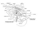
- FIG. 2shows one embodiment of the disclosed technology in which a uterine manipulator is inserted transcervically to press the uterus anteriorly into a partially filled bladder, thereby optimizing both the shape and size of the bladder.
- FIGS. 3A and 3Bare sagittal and frontal views of an acoustic window created with one particular embodiment of the disclosed technology.
- FIGS. 4A and 4Bare laparoscopic photos that illustrate how elevation of the uterus allows it to push into the bladder, causing the latter to spread laterally and conform closely to the uterine surface.
- FIG. 5illustrates a system for automatically controlling fluid delivered to or removed from a bladder and the position of a uterus to increase the size of the acoustic window in accordance with an embodiment of the disclosed technology.
- FIGS. 6A-6Cillustrate uterine manipulators in accordance with embodiments of the disclosed technology.
- uterine tissueshould be considered to include any normal or pathological tissue within or connected to the uterus, including but not limited to myometrium, endometrium, cervix, serosa, fibroids, adenomyosis, polyps, et. al.
- bowelis meant to include small and large intestines.
- HIFUstands for “high intensity focused ultrasound”, but should be considered interchangeable herein with the term “therapeutic ultrasound” (which is not necessarily focused).
- Acoustic windowrefers to the lateral dimensions of the path between the abdominal skin surface and the underlying uterus that is substantially free of obstacles to ultrasound transmission (including but not limited to the bowel).
- Transabdominalrefers to the application of ultrasound from a probe placed on the skin of the abdomen.
- Digital manipulationrefers to use of one or more fingers inserted transvaginally or transrectally to manipulate the position of the uterus or cervix.
- FIG. 1Aillustrates a problem that the disclosed technology is designed to address.
- a patient requiring the application of HIFU to a target area in a uterus 20has an empty or nearly empty bladder 24 .
- the internal organs in the abdomen and pelvic cavityare soft and movable, portions of the patient's bowel 26 can move into the area between the abdomen 28 , where a HIFU transducer will be placed, and the target area of the uterus 20 .
- gas in the bowelcan reflect HIFU energy in a manner that limits the treatment of the uterus and can cause potential burning of the bowel.
- FIG. 1Billustrates one conventional technique for improving transabdominal ultrasound imaging, in which the bladder 24 is naturally or artificially filled to push the bowel tissue 26 laterally out of the path between an ultrasound probe (not shown but would be placed on the abdominal skin) and the uterus 20 .
- the bowel 26typically contains gas which is highly reflective, and thus its presence in the ultrasound path can reduce imaging quality of the underlying uterus.
- fluid in the bladder 24is relatively transparent to ultrasound.
- this known techniquecomes with an undesirable side effect, i.e. as the bladder fills, the bladder expands posteriorly away from the abdomen 28 (as well as laterally), which pushes the uterus farther from the ultrasound probe and thereby tends to degrade image quality.
- Uterine depthis even more critical for HIFU treatment, given the practical limitations on HIFU focal range, which may prevent the ability to treat beyond a certain depth.
- FIG. 2shows one embodiment of the disclosed technology in which a uterine manipulator 30 is inserted transcervically and manipulated to press the uterus 20 anteriorly into a partially filled bladder 24 , thereby optimizing both the shape and size of the bladder 24 .
- the bladder 24is partially filled either naturally with urine or artificially by filling the bladder with saline or other liquid via a catheter.
- a pressure monitormay be used to control an amount of liquid added to or removed from the bladder to maintain it at a desired level of fill.
- the bladder 24 partially filledthe bladder is able to be compressed like a thick pancake by the uterus 20 that is moved with the uterine manipulator 30 .
- the anterior compression of the uterus toward the abdominal wallcauses the bladder to push any bowel tissue out of the way and increases the lateral width of the acoustic window, while simultaneously reducing the required focal depth to reach target tissue within the uterus 20 .
- FIGS. 3A and 3Bprovides alternate sketches of the techniques disclosed herein, including sagittal and frontal views.
- the sagittal view shown in FIG. 3Aillustrates how a patient's bowel 26 is moved laterally out of the way by the anterior compression of the uterus 20 into the partially filled bladder 24 .
- an acoustic window 35 created between the HIFU applicator 33 and a target treatment area in the uterusis free from bowel tissue.
- the frontal view shown in FIG. 3Billustrates how the uterus 20 is located directly posterior to the bladder 24 , allowing the latter displace any bowel tissue that may be present between the HIFU applicator and the desired treatment area in the uterus.
- FIGS. 4A and 4Bare laparoscopic photos to illustrate certain aspects of the disclosed technology.
- the uterusis not manipulated and is not in contact with the overlying bladder.
- a uterine manipulator(not shown) is used to elevate the uterus anteriorly into the bladder, causing the relatively pliable partially-filled bladder to conform to the anterior surface of the uterus.
- surrounding bowelwould be pushed away by the resulting lateral expansion of the bladder.
- One embodiment of the disclosed technologyemploys a transcervical element (solid or with hollow cannula for injecting fluid), with or without an atraumatic lip or lever arm that fits around or posterior to the cervix (e.g. in the posterior vaginal fomix) to aid in elevating the uterus.
- a transcervical elementsolid or with hollow cannula for injecting fluid
- an atraumatic lip or lever armfits around or posterior to the cervix (e.g. in the posterior vaginal fomix) to aid in elevating the uterus.
- Such a designmay eliminate the need for either an intracavitary element (which could interfere with HIFU transmission) or a tenaculum (which may cause pain and/or bleeding).
- manipulationcould be achieved via more conventional instruments which typically include some combination of: a transcervical element or cone, a cannula for injecting fluid into cavity, an intracavitary balloon, an articulating mechanism, and/or a tenaculum to help hold the transcervical element in position.
- a transcervical element or conetypically includes some combination of: a transcervical element or cone, a cannula for injecting fluid into cavity, an intracavitary balloon, an articulating mechanism, and/or a tenaculum to help hold the transcervical element in position.
- Such instrumentationmay also be designed to lock the uterus in a desired position, thereby freeing the physician's hands for other purposes.
- transvaginal instrumentationis used to manipulate the uterus, it may or may not penetrate the cervical os. If it does so (e.g. a transcervical uterine manipulator), the instrumentation may or may not have a retaining balloon, which inflates inside the uterine cavity or cervical canal.
- the instrumentationmay also have one or more portions (which may include a retaining balloon if present) that are specifically designed to reflect ultrasound energy, so as to facilitate visualization of its position during ultrasound imaging, serve as a point reflective source for time reversal correction of HIFU beam aberration, or aid in controlling HIFU effects in surrounding tissue.
- the instrumentationmay have one or more portions that are specifically designed to absorb ultrasound energy, so as to enhance the deposition of HIFU energy in surrounding tissue.
- the instrumentationmay be designed with portions that are relatively transparent to ultrasound energy, so as to avoid affecting HIFU or ultrasound imaging.
- the instrumentationcan have a retaining balloon that conforms to the uterine cavity and selectively absorbs HIFU energy to aid in ablating the endometrial lining.
- Such instrumentationmay also be designed to be compatible with the use of MRI imaging (i.e. non-ferrous components), and could also be designed to enhance the instrumentation's visibility on MRI imaging.
- Such instrumentation (or attached balloons)may also include one or more temperature sensors to monitor surrounding tissue temperatures during HIFU treatment.
- transvaginal instrumentationmay also include a port for injecting fluid or gas into the uterine cavity and/or cervical canal.
- injection of a small amount of saline solutioncould be used if necessary to aid in visualization of the uterine cavity, e.g. to aid in targeting the endometrial lining and/or fibroids.
- fluid or gascould also include compounds, particles or bubbles which reflect ultrasound, so as to facilitate visualization of the uterine cavity on ultrasound imaging and/or aid in controlling HIFU effects in surrounding tissue.
- such fluid or gasmay include compounds, particles or bubbles which absorb ultrasound, so as to enhance the deposition of HIFU energy in surrounding tissue (including but not limited to the endometrial lining).
- the uterusmay be manipulated once at the beginning of a procedure, or its position may be adjusted intermittently or continually to aid in targeting of the ultrasound. This repositioning may be performed manually or automatically in response to various parameters.
- counter compressionmay also be applied to the ultrasound applicator (on abdominal skin surface) to assist in optimizing the acoustic window and target tissue depth.
- These techniques disclosedare preferably practiced with patient in a supine or seated position, with or without inclination of the torso to aid in shifting intestines out of the acoustic window.
- Such positionsfacilitate the use of HIFU to treat the uterus in a convenient low-cost office setting, since most gynecology offices already have examining tables which can accommodate such positions.
- the disclosed techniquesmay also be practiced with patient in prone or other positions.
- the bladder fill volumeis chosen such that bladder can be compressed to minimal dimensions in the anterior-posterior direction, while maximizing its dimensions in the caudal-cephalic and side to side directions.
- the volumeshould also be kept low enough to maintain bladder pliability, so as to maximize the contact area between posterior abdominal wall and anterior bladder, and between posterior bladder and anterior uterus. This will exclude any intervening bowel between these surfaces and thus maximize the lateral dimensions of the acoustic window.
- Bladder fillmay be accomplished by a variety of techniques, including having patient arrive with a partially full bladder. If bladder is too full upon arrival, patient may void a measured amount, repeating this procedure until bladder reaches the desired size and degree of pliability.
- a cathetermay be inserted into the bladder via the urethra to allow one-time or periodic addition or extraction of fluid from the bladder.
- ongoing control of bladder volumemay be accomplished via an indwelling catheter (with or without a retaining balloon).
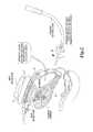
- FIG. 5is a block diagram of a system for automatically controlling the fill of a bladder and the position of the uterus to optimize the acoustic window and treat the uterus with HIFU in accordance with the disclosed technology.
- a HIFU controller 40has hardware adapted to deliver HIFU energy though a HIFU transducer 33 to the patient. Images of the tissue being treated can be obtained either through imaging transducer elements on the HIFU transducer 33 or from a separate imaging transducer 56 . The images of the tissue are displayed on a conventional ultrasound monitor 42 .
- the HIFU controller 40controls the acoustic window through which HIFU energy is delivered to a uterus by selectively adding liquid to, or removing liquid from the patient's bladder 24 .
- the HIFU controller 40controls a pump 44 that delivers liquid from a liquid source 46 into a catheter that is inserted into the bladder.
- the cathetercan include a pressure sensor that produces signals read by a processor in the controller to monitor the liquid pressure in the bladder.
- the processor within controller 40directs a valve 48 to be opened to allow liquid to drain from the bladder or closed to seal the liquid in the bladder.
- a uterine manipulator 30is engaged with the uterus 20 and manipulated by a hydraulic piston, pneumatic cylinder, motor or a similar mechanism that controls the manipulator to move the uterus either in the anterior direction towards the bladder or in the posterior direction away from the bladder.
- movement towards the bladdercompresses the bladder and pushes any bowel tissue out of the acoustic window 35 .
- the HIFU controller 40operates to remove bowel tissue from the acoustic window and reduces the depth required for the HIFU transducer 33 to treat the uterus 20 .
- the anterior/posterior position of the uterus with respect to HIFU applicator 33could be adjusted by other methods including but not limited to: controlling the pressure on or vertical position of the applicator, or controlling the inflation of a rectal balloon.
- a processor within the controller 40is programmed to analyze images obtained of the acoustic window. Any bright reflections around the periphery of the acoustic window or other reflections that may indicate that bowel tissue is in the acoustic window are detected. The HIFU controller 40 then adjusts either or both of the filling of the bladder and movement of the uterine manipulator to remove the source of reflections from the acoustic window. Continuous or intermittent control could be performed manually or automatically.
- the systemcan also set bladder fill volume in response to factors which might include (but are not limited to): position of and/or downward pressure exerted on the transabdominal applicator, position of and/or upward pressure exerted on the uterus, pressure within bladder, and location of target tissue relative to the ultrasound applicator.
- the uterusmay be large enough to make direct contact with the abdominal wall everywhere within the intended HIFU beam path. In this case, there is no need to interpose the bladder, since direct contact would necessarily exclude the possibility of intervening bowel.
- the ultrasound applicatorcan be pressed down against the abdominal wall, and/or the uterus can be manipulated upward toward the abdominal wall.
- manipulation of the uteruscan be performed by a variety of techniques including digits (fingers) inserted transvaginally or transrectally, instruments placed in vaginal fornices or on the cervix and/or a transrectal instrument, enema or balloon.
- the techniques described hereinwill typically require only simple elevation of the uterus in an anterior direction (as opposed to surgical procedures which may require ability to manipulate the uterus more robustly and/or in multiple directions).
- the design of instrumentation to manipulate the uteruscan be improved to be less traumatic or painful, thus minimizing the need for anesthesia during its insertion, manipulation or removal.
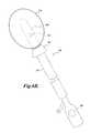
- FIGS. 6A-6Cillustrate a number of alternative embodiments of a uterine manipulator that are useful with the disclosed technology.
- a uterine manipulatoris designed to be substantially transparent to an applied HIFU beam.
- a uterine manipulator 100includes an outer sleeve 102 and an inner shaft 106 that can be advanced or retracted with respect to the outer sleeve.
- the distal end of the inner shaft 106may include one or more ports 108 that are used for the delivery or extraction of fluids from the uterine cavity. Such fluids may aid visualization of the uterus during ultrasound imaging, or may be intended to cool the uterus or otherwise interact with HIFU to affect treatment of surrounding tissue, or may contain drugs to directly treat the uterine tissue.
- the ports 108are in fluid communication with a fluid lumen (not shown) within the inner shaft that terminates at a fluid port 110 .
- the distal end of the inner shaftmay also include one or more sensors such as pressure sensors or temperature sensors produce signals that can be detected to inform the physician of conditions that are occurring in the uterus during treatment
- a handlethat includes controls to selectively tighten or relax controls wires within the inner shaft 106 .
- the control wiresare secured at their distal end to the distal end of the inner shaft such that tension on the controls wires cause the distal end of the shaft to bend in a desired direction in manner similar to a steerable catheter or endoscope.
- the inner shaftpreferably includes an articulation joint near its distal end to aid in bending under tension of the control wires. Depending on the number of control wires and the configuration of the articulation joint, the distal tip of the inner shaft 106 can move in two or more directions.
- a flange 103 made of a biocompatible material (rubber etc.)is positioned at the distal end of the outer sleeve 102 .
- the flange 103is engaged with the opening of the cervix and serves to aid in controlling uterine position as well as sealing the uterus to keep in any liquids.
- the distal end of the inner shaft 106is at least partially made of materials that are substantially transparent to HIFU energy. Such materials tend to match the acoustic impedance of the uterine tissue and have low acoustic attenuation with no specular or Rayleigh scatterers.
- Exemplary materials that exhibit good transparency to HIFU energyinclude cis-1,4 polybutadiene with ⁇ 0.5% peroxide linker available from Lanxess Corp., TPX (Polymethylpentene Copolymer) available from Mitsui Chemicals America; RTV-616 and RTV-630 (unloaded) available from Momentive Performance Materials (formerly GE Silicones); Castall U-2941 (Urethane; now relabeled as Circalok 6414) available from Lord Corp.
- a stiffening membersuch as a stainless steel rod, may be included in the distal tip of the inner shaft to provide sufficient strength such that movement of the distal tip with the control wires can move and hold the uterus in the desired position.
- the stiffening membermay be coupled to a heat sink or in thermal contact with liquids delivered from the ports 108 (or other cooling channels in the shaft) to prevent the rod from becoming excessively hot as HIFU energy is applied.
- a uterine manipulatoris at least partially constructed of material that is highly absorptive of HIFU. Absorptive materials have a good match to the acoustic impedance of tissue, yet high acoustic attenuation of HIFU and contain only low to moderate Rayleigh scatterers.
- EngageTMPolyolefin Elastomer
- SurlynTMThermoplastic Ionomer
- SantopreneTMThermoplastic Elastomer
- a uterine manipulator 150has an outer sleeve 152 with a conical flange 153 at the distal end thereof that operates to stabilize the manipulator in relation to the uterus and to seal any liquids that may be delivered into the uterus.
- An inner shaft 160is movable with respect to the outer sleeve 152 such that it can be inserted into or removed from the uterine cavity to a desired degree while the flange is engaged to the uterus.
- the inner shaft 160may include one or more ports from which a liquid can be delivered to or withdraw from the uterus.
- the inner shaft 160may include a handle 166 with controls for manipulating controls wires as described above.
- the distal end of the inner shaft 160includes a balloon 170 that is made of, or coated with, absorptive materials of the type described above.
- a balloon 170When inflated with a liquid or gas, the balloon 170 engages and conforms to the endometrial wall of the uterus.
- the application of HIFU energy when the balloon 170 is deployedcauses the balloon to become heated in order to thermally treat the lining of the uterus.
- the balloon 170can be coated with, or made from, a material that is reflective of HIFU energy in order to reflect HIFU energy away from the center of the uterus.
- a material that is reflective of HIFU energyinclude stainless steel, aluminum, titanium or alumina
- the balloon itselfmay not be absorptive or reflective, but may be filled with fluid which is absorptive or reflective.
- FIG. 6Cillustrates yet another embodiment of a uterine manipulator.
- a uterine manipulator 200includes an outer shaft 202 with a conical flange 204 at the distal end.
- An inner shaft 210is movable with respect to the outer shaft 202 such that a distal end of the inner shaft can be selectively inserted into and removed from a uterus.
- the inner shafthas a number of support splines 220 that expand radially outwards when the inner shaft is pushed out of the distal end of the outer shaft 202 .
- the support splines 220support one or more sheets 224 of material that is absorptive or reflective of HIFU energy and are shaped to substantially fill the uterus when the support splines 220 are extended.
- the support splinesare sufficiently stiff such that force on the more proximal portions of the inner shaft 210 or the outer sleeve 202 can move and manipulate the position of the uterus.
- the application of HIFU energywill cause the sheets to heat or to reflect HIFU energy.
Landscapes
- Health & Medical Sciences (AREA)
- Life Sciences & Earth Sciences (AREA)
- Surgery (AREA)
- Veterinary Medicine (AREA)
- General Health & Medical Sciences (AREA)
- Biomedical Technology (AREA)
- Nuclear Medicine, Radiotherapy & Molecular Imaging (AREA)
- Engineering & Computer Science (AREA)
- Public Health (AREA)
- Animal Behavior & Ethology (AREA)
- Medical Informatics (AREA)
- Molecular Biology (AREA)
- Heart & Thoracic Surgery (AREA)
- Gynecology & Obstetrics (AREA)
- Pregnancy & Childbirth (AREA)
- Reproductive Health (AREA)
- Radiology & Medical Imaging (AREA)
- Surgical Instruments (AREA)
- Ultra Sonic Daignosis Equipment (AREA)
Abstract
Description
Claims (34)
Priority Applications (1)
| Application Number | Priority Date | Filing Date | Title |
|---|---|---|---|
| US12/641,248US9144421B1 (en) | 2008-12-17 | 2009-12-17 | Optimization of acoustic window and target depth for transabdominal ultrasound treatment or imaging of the uterus |
Applications Claiming Priority (2)
| Application Number | Priority Date | Filing Date | Title |
|---|---|---|---|
| US13840008P | 2008-12-17 | 2008-12-17 | |
| US12/641,248US9144421B1 (en) | 2008-12-17 | 2009-12-17 | Optimization of acoustic window and target depth for transabdominal ultrasound treatment or imaging of the uterus |
Publications (1)
| Publication Number | Publication Date |
|---|---|
| US9144421B1true US9144421B1 (en) | 2015-09-29 |
Family
ID=54149475
Family Applications (1)
| Application Number | Title | Priority Date | Filing Date |
|---|---|---|---|
| US12/641,248Expired - Fee RelatedUS9144421B1 (en) | 2008-12-17 | 2009-12-17 | Optimization of acoustic window and target depth for transabdominal ultrasound treatment or imaging of the uterus |
Country Status (1)
| Country | Link |
|---|---|
| US (1) | US9144421B1 (en) |
Cited By (11)
| Publication number | Priority date | Publication date | Assignee | Title |
|---|---|---|---|---|
| US20150164553A1 (en)* | 2013-12-13 | 2015-06-18 | Boston Scientific Scimed, Inc. | Adjustable medical devices and methods for manipulating bodily tissues |
| US20150306429A1 (en)* | 2012-12-10 | 2015-10-29 | Arizona Board Of Regents On Behalf Of Arizona State University | Methods and Apparatus for Treating a Cervix with Ultrasound Energy |
| WO2017081138A1 (en)* | 2015-11-10 | 2017-05-18 | Koninklijke Philips N.V. | An acoustic window layer for an ultrasound array |
| US11160597B2 (en) | 2010-11-09 | 2021-11-02 | Aegea Medical Inc. | Positioning method and apparatus for delivering vapor to the uterus |
| US11207118B2 (en) | 2007-07-06 | 2021-12-28 | Tsunami Medtech, Llc | Medical system and method of use |
| US11213338B2 (en) | 2007-08-23 | 2022-01-04 | Aegea Medical Inc. | Uterine therapy device and method |
| US11219479B2 (en) | 2014-05-22 | 2022-01-11 | Aegea Medical Inc. | Integrity testing method and apparatus for delivering vapor to the uterus |
| US11331037B2 (en) | 2016-02-19 | 2022-05-17 | Aegea Medical Inc. | Methods and apparatus for determining the integrity of a bodily cavity |
| US11419574B2 (en) | 2019-03-08 | 2022-08-23 | Samsung Medison Co., Ltd. | Ultrasound imaging apparatus, method of controlling the same, and computer program product |
| US11497089B2 (en) | 2017-06-20 | 2022-11-08 | Aegea Medical Inc. | Induction coil assembly for uterine ablation and method |
| US11849991B2 (en) | 2011-10-07 | 2023-12-26 | Aegea Medical Inc. | Integrity testing method and apparatus for delivering vapor to the uterus |
Citations (47)
| Publication number | Priority date | Publication date | Assignee | Title |
|---|---|---|---|---|
| US3470868A (en) | 1964-06-06 | 1969-10-07 | Siemens Ag | Ultrasound diagnostic apparatus |
| US3480002A (en) | 1967-01-24 | 1969-11-25 | Magnaflux Corp | Medical ultrasonic scanning system |
| US3676584A (en) | 1970-07-13 | 1972-07-11 | Chris J Plakas | Echo coincidence ultrasonic scanning |
| US4059098A (en) | 1975-07-21 | 1977-11-22 | Stanford Research Institute | Flexible ultrasound coupling system |
| US4097835A (en) | 1976-09-20 | 1978-06-27 | Sri International | Dual transducer arrangement for ultrasonic imaging system |
| US4185502A (en) | 1977-10-11 | 1980-01-29 | Ralph Frank | Transducer coupling apparatus |
| US4347850A (en) | 1980-03-19 | 1982-09-07 | Indianapolis Center For Advanced Research, Inc. | Direct water coupling device for ultrasound breast scanning in a supine position |
| US4484569A (en) | 1981-03-13 | 1984-11-27 | Riverside Research Institute | Ultrasonic diagnostic and therapeutic transducer assembly and method for using |
| US4742829A (en) | 1986-08-11 | 1988-05-10 | General Electric Company | Intracavitary ultrasound and biopsy probe for transvaginal imaging |
| US4756313A (en) | 1986-11-05 | 1988-07-12 | Advanced Diagnostic Medical Systems, Inc. | Ultrasonic probe |
| US4817616A (en) | 1987-10-30 | 1989-04-04 | Wayne State University | Auto switch biplane prostate probe |
| US4858613A (en) | 1988-03-02 | 1989-08-22 | Laboratory Equipment, Corp. | Localization and therapy system for treatment of spatially oriented focal disease |
| US4893624A (en) | 1988-06-21 | 1990-01-16 | Massachusetts Institute Of Technology | Diffuse focus ultrasound hyperthermia system |
| US4932414A (en) | 1987-11-02 | 1990-06-12 | Cornell Research Foundation, Inc. | System of therapeutic ultrasound and real-time ultrasonic scanning |
| US4938217A (en) | 1988-06-21 | 1990-07-03 | Massachusetts Institute Of Technology | Electronically-controlled variable focus ultrasound hyperthermia system |
| US5050610A (en) | 1990-11-14 | 1991-09-24 | Advanced Technology Laboratories, Inc. | Transesophageal ultrasonic scanhead |
| JPH0523336A (en) | 1991-07-19 | 1993-02-02 | Fujitsu Ltd | Ultrasonic probe |
| US5492126A (en) | 1994-05-02 | 1996-02-20 | Focal Surgery | Probe for medical imaging and therapy using ultrasound |
| US5520188A (en) | 1994-11-02 | 1996-05-28 | Focus Surgery Inc. | Annular array transducer |
| US5882302A (en) | 1992-02-21 | 1999-03-16 | Ths International, Inc. | Methods and devices for providing acoustic hemostasis |
| US6050943A (en) | 1997-10-14 | 2000-04-18 | Guided Therapy Systems, Inc. | Imaging, therapy, and temperature monitoring ultrasonic system |
| US6068653A (en) | 1992-11-13 | 2000-05-30 | Scimed Life Systems, Inc. | Electrophysiology catheter device |
| US6254601B1 (en) | 1998-12-08 | 2001-07-03 | Hysterx, Inc. | Methods for occlusion of the uterine arteries |
| US6425867B1 (en) | 1998-09-18 | 2002-07-30 | University Of Washington | Noise-free real time ultrasonic imaging of a treatment site undergoing high intensity focused ultrasound therapy |
| US6451013B1 (en) | 2000-01-19 | 2002-09-17 | Medtronic Xomed, Inc. | Methods of tonsil reduction using high intensity focused ultrasound to form an ablated tissue area containing a plurality of lesions |
| JP2002536040A (en) | 1999-02-02 | 2002-10-29 | トランサージカル,インコーポレイテッド | High intensity focused ultrasound applicator in the body |
| US20030018255A1 (en)* | 1997-10-31 | 2003-01-23 | Martin Roy W. | Method and apparatus for medical procedures using high-intensity focused ultrasound |
| US6613004B1 (en) | 2000-04-21 | 2003-09-02 | Insightec-Txsonics, Ltd. | Systems and methods for creating longer necrosed volumes using a phased array focused ultrasound system |
| US20030233045A1 (en) | 2002-05-30 | 2003-12-18 | University Of Washington | Solid hydrogel coupling for ultrasound imaging and therapy |
| US6676601B1 (en) | 1999-05-26 | 2004-01-13 | Technomed Medical Systems, S.A. | Apparatus and method for location and treatment using ultrasound |
| US6692450B1 (en) | 2000-01-19 | 2004-02-17 | Medtronic Xomed, Inc. | Focused ultrasound ablation devices having selectively actuatable ultrasound emitting elements and methods of using the same |
| US20040082859A1 (en) | 2002-07-01 | 2004-04-29 | Alan Schaer | Method and apparatus employing ultrasound energy to treat body sphincters |
| US20040152986A1 (en) | 2003-01-23 | 2004-08-05 | Fidel Howard F. | Ultrasonic imaging device, system and method of use |
| US6840936B2 (en) | 1996-10-22 | 2005-01-11 | Epicor Medical, Inc. | Methods and devices for ablation |
| US20050038340A1 (en)* | 1998-09-18 | 2005-02-17 | University Of Washington | Use of contrast agents to increase the effectiveness of high intensity focused ultrasound therapy |
| US20050084538A1 (en) | 2003-08-27 | 2005-04-21 | The Regents Of The University Of California, A California Corporation | Ultrasonic concentration of drug delivery capsules |
| US20050107702A1 (en) | 2001-11-05 | 2005-05-19 | Shenxu He | External high-power focusing ultrasonic treatment |
| US20050149101A1 (en)* | 2002-02-27 | 2005-07-07 | Abdolhamid Huschmand Nia | Non-traumatic surgical kit for uterine operations |
| US6936046B2 (en) | 2000-01-19 | 2005-08-30 | Medtronic, Inc. | Methods of using high intensity focused ultrasound to form an ablated tissue area containing a plurality of lesions |
| US7105007B2 (en) | 2002-11-21 | 2006-09-12 | Hibler Timothy B | Cervical medical device, system and method |
| US20060216275A1 (en)* | 2005-03-24 | 2006-09-28 | Celsion Corporation | Apparatus and method for pre-conditioning/fixation and treatment of disease with heat activation/release with thermoactivated drugs and gene products |
| US20070066990A1 (en) | 2005-09-19 | 2007-03-22 | Andrew Marsella | Device for forming a fluid tight seal during a procedure within a hollow organ |
| US20070071683A1 (en) | 2005-09-27 | 2007-03-29 | The Regents Of The University Of California | Ultrasonic concentration of carrier particles |
| US20070194658A1 (en) | 2005-07-13 | 2007-08-23 | Jimin Zhang | Systems and methods for performing acoustic hemostasis of deep bleeding trauma in limbs |
| US7297116B2 (en)* | 2003-04-21 | 2007-11-20 | Wisconsin Alumni Research Foundation | Method and apparatus for imaging the cervix and uterine wall |
| US7470241B2 (en) | 1999-11-26 | 2008-12-30 | Therus Corporation | Controlled high efficiency lesion formation using high intensity ultrasound |
| US7591794B2 (en) | 2003-01-14 | 2009-09-22 | Edap S.A. | Therapy probe |
- 2009
- 2009-12-17USUS12/641,248patent/US9144421B1/ennot_activeExpired - Fee Related
Patent Citations (54)
| Publication number | Priority date | Publication date | Assignee | Title |
|---|---|---|---|---|
| US3470868A (en) | 1964-06-06 | 1969-10-07 | Siemens Ag | Ultrasound diagnostic apparatus |
| US3480002A (en) | 1967-01-24 | 1969-11-25 | Magnaflux Corp | Medical ultrasonic scanning system |
| US3676584A (en) | 1970-07-13 | 1972-07-11 | Chris J Plakas | Echo coincidence ultrasonic scanning |
| US4059098A (en) | 1975-07-21 | 1977-11-22 | Stanford Research Institute | Flexible ultrasound coupling system |
| US4097835A (en) | 1976-09-20 | 1978-06-27 | Sri International | Dual transducer arrangement for ultrasonic imaging system |
| US4185502A (en) | 1977-10-11 | 1980-01-29 | Ralph Frank | Transducer coupling apparatus |
| US4347850A (en) | 1980-03-19 | 1982-09-07 | Indianapolis Center For Advanced Research, Inc. | Direct water coupling device for ultrasound breast scanning in a supine position |
| US4484569A (en) | 1981-03-13 | 1984-11-27 | Riverside Research Institute | Ultrasonic diagnostic and therapeutic transducer assembly and method for using |
| US4742829A (en) | 1986-08-11 | 1988-05-10 | General Electric Company | Intracavitary ultrasound and biopsy probe for transvaginal imaging |
| US4756313A (en) | 1986-11-05 | 1988-07-12 | Advanced Diagnostic Medical Systems, Inc. | Ultrasonic probe |
| US4817616A (en) | 1987-10-30 | 1989-04-04 | Wayne State University | Auto switch biplane prostate probe |
| US4932414A (en) | 1987-11-02 | 1990-06-12 | Cornell Research Foundation, Inc. | System of therapeutic ultrasound and real-time ultrasonic scanning |
| US4858613A (en) | 1988-03-02 | 1989-08-22 | Laboratory Equipment, Corp. | Localization and therapy system for treatment of spatially oriented focal disease |
| US4893624A (en) | 1988-06-21 | 1990-01-16 | Massachusetts Institute Of Technology | Diffuse focus ultrasound hyperthermia system |
| US4938217A (en) | 1988-06-21 | 1990-07-03 | Massachusetts Institute Of Technology | Electronically-controlled variable focus ultrasound hyperthermia system |
| US5050610A (en) | 1990-11-14 | 1991-09-24 | Advanced Technology Laboratories, Inc. | Transesophageal ultrasonic scanhead |
| JPH0523336A (en) | 1991-07-19 | 1993-02-02 | Fujitsu Ltd | Ultrasonic probe |
| US5882302A (en) | 1992-02-21 | 1999-03-16 | Ths International, Inc. | Methods and devices for providing acoustic hemostasis |
| US6068653A (en) | 1992-11-13 | 2000-05-30 | Scimed Life Systems, Inc. | Electrophysiology catheter device |
| US5492126A (en) | 1994-05-02 | 1996-02-20 | Focal Surgery | Probe for medical imaging and therapy using ultrasound |
| US5520188A (en) | 1994-11-02 | 1996-05-28 | Focus Surgery Inc. | Annular array transducer |
| US6840936B2 (en) | 1996-10-22 | 2005-01-11 | Epicor Medical, Inc. | Methods and devices for ablation |
| US6050943A (en) | 1997-10-14 | 2000-04-18 | Guided Therapy Systems, Inc. | Imaging, therapy, and temperature monitoring ultrasonic system |
| US20030018255A1 (en)* | 1997-10-31 | 2003-01-23 | Martin Roy W. | Method and apparatus for medical procedures using high-intensity focused ultrasound |
| US6425867B1 (en) | 1998-09-18 | 2002-07-30 | University Of Washington | Noise-free real time ultrasonic imaging of a treatment site undergoing high intensity focused ultrasound therapy |
| US20050038340A1 (en)* | 1998-09-18 | 2005-02-17 | University Of Washington | Use of contrast agents to increase the effectiveness of high intensity focused ultrasound therapy |
| US7686763B2 (en) | 1998-09-18 | 2010-03-30 | University Of Washington | Use of contrast agents to increase the effectiveness of high intensity focused ultrasound therapy |
| US6602251B2 (en) | 1998-12-08 | 2003-08-05 | Vascular Control Systems, Inc. | Device and methods for occlusion of the uterine artieries |
| US6764488B1 (en) | 1998-12-08 | 2004-07-20 | Vascular Control Systems, Inc. | Devices and methods for occlusion of the uterine arteries |
| US6254601B1 (en) | 1998-12-08 | 2001-07-03 | Hysterx, Inc. | Methods for occlusion of the uterine arteries |
| JP2002536040A (en) | 1999-02-02 | 2002-10-29 | トランサージカル,インコーポレイテッド | High intensity focused ultrasound applicator in the body |
| US6676601B1 (en) | 1999-05-26 | 2004-01-13 | Technomed Medical Systems, S.A. | Apparatus and method for location and treatment using ultrasound |
| US7470241B2 (en) | 1999-11-26 | 2008-12-30 | Therus Corporation | Controlled high efficiency lesion formation using high intensity ultrasound |
| US6936046B2 (en) | 2000-01-19 | 2005-08-30 | Medtronic, Inc. | Methods of using high intensity focused ultrasound to form an ablated tissue area containing a plurality of lesions |
| US6451013B1 (en) | 2000-01-19 | 2002-09-17 | Medtronic Xomed, Inc. | Methods of tonsil reduction using high intensity focused ultrasound to form an ablated tissue area containing a plurality of lesions |
| US6692450B1 (en) | 2000-01-19 | 2004-02-17 | Medtronic Xomed, Inc. | Focused ultrasound ablation devices having selectively actuatable ultrasound emitting elements and methods of using the same |
| US20050267454A1 (en) | 2000-01-19 | 2005-12-01 | Medtronic, Inc. | Methods of using high intensity focused ultrasound to form an ablated tissue area containing a plurality of lesions |
| US6613004B1 (en) | 2000-04-21 | 2003-09-02 | Insightec-Txsonics, Ltd. | Systems and methods for creating longer necrosed volumes using a phased array focused ultrasound system |
| US20050107702A1 (en) | 2001-11-05 | 2005-05-19 | Shenxu He | External high-power focusing ultrasonic treatment |
| US20050149101A1 (en)* | 2002-02-27 | 2005-07-07 | Abdolhamid Huschmand Nia | Non-traumatic surgical kit for uterine operations |
| US20030233045A1 (en) | 2002-05-30 | 2003-12-18 | University Of Washington | Solid hydrogel coupling for ultrasound imaging and therapy |
| US7070565B2 (en) | 2002-05-30 | 2006-07-04 | University Of Washington | Solid hydrogel coupling for ultrasound imaging and therapy |
| US20040082859A1 (en) | 2002-07-01 | 2004-04-29 | Alan Schaer | Method and apparatus employing ultrasound energy to treat body sphincters |
| US7105007B2 (en) | 2002-11-21 | 2006-09-12 | Hibler Timothy B | Cervical medical device, system and method |
| US7591794B2 (en) | 2003-01-14 | 2009-09-22 | Edap S.A. | Therapy probe |
| US20040152986A1 (en) | 2003-01-23 | 2004-08-05 | Fidel Howard F. | Ultrasonic imaging device, system and method of use |
| US7090643B2 (en) | 2003-01-23 | 2006-08-15 | 3G Ultrasound, Inc. | Ultrasonic imaging device, system and method of use |
| US7297116B2 (en)* | 2003-04-21 | 2007-11-20 | Wisconsin Alumni Research Foundation | Method and apparatus for imaging the cervix and uterine wall |
| US7358226B2 (en) | 2003-08-27 | 2008-04-15 | The Regents Of The University Of California | Ultrasonic concentration of drug delivery capsules |
| US20050084538A1 (en) | 2003-08-27 | 2005-04-21 | The Regents Of The University Of California, A California Corporation | Ultrasonic concentration of drug delivery capsules |
| US20060216275A1 (en)* | 2005-03-24 | 2006-09-28 | Celsion Corporation | Apparatus and method for pre-conditioning/fixation and treatment of disease with heat activation/release with thermoactivated drugs and gene products |
| US20070194658A1 (en) | 2005-07-13 | 2007-08-23 | Jimin Zhang | Systems and methods for performing acoustic hemostasis of deep bleeding trauma in limbs |
| US20070066990A1 (en) | 2005-09-19 | 2007-03-22 | Andrew Marsella | Device for forming a fluid tight seal during a procedure within a hollow organ |
| US20070071683A1 (en) | 2005-09-27 | 2007-03-29 | The Regents Of The University Of California | Ultrasonic concentration of carrier particles |
Non-Patent Citations (22)
| Title |
|---|
| "ThermoDox(TM) Animal Studies to Be Presented at 6th International Symposium on Therapeutic Ultrasound in Oxford, England," Aug. 30-Sep. 2, 2006, Celsion, Inc., [retrieved Oct. 8, 2007], 2 pages. |
| "ThermoDox(TM): Heat-Activated Liposome Drug," © 2007 Celsion, Inc., [retrieved Oct. 8, 2007], 3 pages. |
| "ThermoDox™ Animal Studies to Be Presented at 6th International Symposium on Therapeutic Ultrasound in Oxford, England," Aug. 30-Sep. 2, 2006, Celsion, Inc.,<http://www.celsion.com/news/releasedetail.dfm> [retrieved Oct. 8, 2007], 2 pages. |
| "ThermoDox™: Heat-Activated Liposome Drug," © 2007 Celsion, Inc., <http://www.celsion.com/products/ThermoDox.cfm> [retrieved Oct. 8, 2007], 3 pages. |
| Chen, L., et al., "Effect of Blood Perfusion on the Ablation of Liver Parenchyma With High-Intensity Focused Ultrasound," Physics in Medicine and Biology 38(11):1661-1673, Nov. 1993. |
| Cheng, S.-Q., et al., "High-Intensity Focused Ultrasound in the Treatment of Experimental Liver Tumour," Journal of Cancer Research and Clinical Oncology 123(4):219-223, Apr. 1997. |
| Delon-Martin, C., et al., "Venous Thrombosis Generation by Means of High-Intensity Focused Ultrasound," Ultrasound in Medicine & Biology 21(1):113-119, 1995. |
| Fennessy, F., A Review of Margnetic Resonance Imaging-Guided Focused Ultrasound Surgery of Uterine Fibroids, Top Magn Reason Imaging 2006; 17: 173-179.* |
| Friedland, F., "Ultrasonic Therapy," American Journal of Nursing 59(9):1272-1275, Sep. 1959. |
| Fry, F.J., "Recent Bioeffects With Ultrasound on the Reproductive System and Solid Tumors," Journal of the Acoustical Society of America 63(Suppl. 1):S13, May 1978. |
| International Search Report and Written Opinion mailed Dec. 27, 2011, issued in International Application No. PCT/US2011/031129, 13 pages. |
| International Search Report and Written Opinion mailed May 11, 2010, issued in International Application No. PCT/US2009/059589, filed Oct. 5, 2009, 10 pages. |
| Lee, J.M., et al., "Comparison of Wet Radiofrequency Ablation With Dry Radiofrequency Ablation and Radiofrequency Ablation Using Hypertonic Saline Preinjection: Ex Vivo Bovine Liver," Korean Journal of Radiology 5(4):258-265, Dec. 2004. |
| Lee, J.M., et al., "Wet Radio-Frequency Ablation Using Multiple Electrodes: Comparative Study of Bipolar Versus Monopolar Modes in the Bovine Liver," European Journal of Radiology 54:408-417, Jun. 2005. |
| Mittleman, R.S., et al., "Use of the Saline Infusion Electrode Catheter for Improved Energy Delivery and Increased Lesion Size in Radiofrequency Catheter Ablation," Pacing and Clinical Electrophysiology 18(5 Pt. 1):953-1081, May 1995. |
| Ngo, F.C., et al., "An Experimental Analysis of a Sector-Vortex Phased Array Prototype," Proceedings of the IEEE Ultrasonics Symposium, Montreal, Oct. 3-6, 1989, vol. 2, pp. 999-1002. |
| Notice of Reasons for Rejection mailed Mar. 12, 2012, issued in Japanese Patent Application No. 2009-505639, filed Apr. 13, 2007, 7 pages. |
| Orsini-Meinhard, K., "UW Tech-Transfer Program Putting Discoveries to Work," The Seattle Times, May 27, 2007, 8 pages. |
| Umemura, S.-I., and C.A. Cain, "Acoustical Evaluation of a Prototype Sector-Vortex Phased-Array Applicator," IEEE Transactions on Ultrasonics, Ferroelectrics, and Frequency Control 39(1):32-38, Jan. 1992. |
| Vaezy, S., et al., "Image-Guided Acoustic Therapy," Annual Review of Biomedical Engineering 3:375-390, Aug. 2001. |
| Yoon, S., Patient selection guidelines in MR-guided focused ultrasound surgery of uterine fibroids: a pictorial guide to relevant findings in screening pelvic MRI, Eur Radiol (2008) 18: 2997-3006.* |
| Zanelli, C.I., et al., "Design and Characterization of a 10 cm Annular Array Transducer for High Intensity Focused Ultrasound (HIFU) Applications," Proceedings of the IEEE Ultrasonics Symposium 3:1887-1890, Cannes, France, Nov. 1-4, 1994. |
Cited By (19)
| Publication number | Priority date | Publication date | Assignee | Title |
|---|---|---|---|---|
| US11207118B2 (en) | 2007-07-06 | 2021-12-28 | Tsunami Medtech, Llc | Medical system and method of use |
| US11213338B2 (en) | 2007-08-23 | 2022-01-04 | Aegea Medical Inc. | Uterine therapy device and method |
| US12279802B2 (en) | 2010-11-09 | 2025-04-22 | Coopersurgical, Inc. | Positioning method and apparatus for delivering vapor to the uterus |
| US11160597B2 (en) | 2010-11-09 | 2021-11-02 | Aegea Medical Inc. | Positioning method and apparatus for delivering vapor to the uterus |
| US11849991B2 (en) | 2011-10-07 | 2023-12-26 | Aegea Medical Inc. | Integrity testing method and apparatus for delivering vapor to the uterus |
| US20150306429A1 (en)* | 2012-12-10 | 2015-10-29 | Arizona Board Of Regents On Behalf Of Arizona State University | Methods and Apparatus for Treating a Cervix with Ultrasound Energy |
| US9855074B2 (en)* | 2013-12-13 | 2018-01-02 | Boston Scientific Scimed, Inc. | Adjustable medical devices and methods for manipulating bodily tissues |
| US20150164553A1 (en)* | 2013-12-13 | 2015-06-18 | Boston Scientific Scimed, Inc. | Adjustable medical devices and methods for manipulating bodily tissues |
| US11219479B2 (en) | 2014-05-22 | 2022-01-11 | Aegea Medical Inc. | Integrity testing method and apparatus for delivering vapor to the uterus |
| CN108348958A (en)* | 2015-11-10 | 2018-07-31 | 皇家飞利浦有限公司 | The sound window layer of supersonic array |
| CN108348958B (en)* | 2015-11-10 | 2020-08-11 | 皇家飞利浦有限公司 | Acoustic window layer for ultrasound array |
| US10736606B2 (en) | 2015-11-10 | 2020-08-11 | Koninklijke Philips N.V. | Acoustic window layer for an ultrasound array |
| WO2017081138A1 (en)* | 2015-11-10 | 2017-05-18 | Koninklijke Philips N.V. | An acoustic window layer for an ultrasound array |
| US11331037B2 (en) | 2016-02-19 | 2022-05-17 | Aegea Medical Inc. | Methods and apparatus for determining the integrity of a bodily cavity |
| US12011283B2 (en) | 2016-02-19 | 2024-06-18 | Aegea Medical Inc. | Methods and apparatus for determining the integrity of a bodily cavity |
| US11497089B2 (en) | 2017-06-20 | 2022-11-08 | Aegea Medical Inc. | Induction coil assembly for uterine ablation and method |
| US11576236B2 (en) | 2017-06-20 | 2023-02-07 | Aegea Medical Inc. | Induction coil assembly for uterine ablation and method |
| US11950348B2 (en) | 2017-06-20 | 2024-04-02 | Aegea Medical Inc. | Induction coil assembly for uterine ablation and method |
| US11419574B2 (en) | 2019-03-08 | 2022-08-23 | Samsung Medison Co., Ltd. | Ultrasound imaging apparatus, method of controlling the same, and computer program product |
Similar Documents
| Publication | Publication Date | Title |
|---|---|---|
| US9144421B1 (en) | Optimization of acoustic window and target depth for transabdominal ultrasound treatment or imaging of the uterus | |
| US6626855B1 (en) | Controlled high efficiency lesion formation using high intensity ultrasound | |
| US12245807B2 (en) | Minimally invasive access channels into bodily regions | |
| US8277379B2 (en) | Methods and apparatus for the treatment of menometrorrhagia, endometrial pathology, and cervical neoplasia using high intensity focused ultrasound energy | |
| US8052604B2 (en) | Methods and apparatus for engagement and coupling of an intracavitory imaging and high intensity focused ultrasound probe | |
| Vitale et al. | Updates in office hysteroscopy: a practical decalogue to perform a correct procedure | |
| CN102065775B (en) | Ultrasound guided systems and methods | |
| US6066132A (en) | Articulating endometrial ablation device | |
| WO2005086737A2 (en) | Intra-cavitary ultrasound medical system and method | |
| JPH11123204A (en) | Infertility treatment apparatus and method | |
| CN105828865A (en) | Device and method for accessing and sealing body vessels and cavities | |
| Sutton | Hysteroscopic surgery | |
| EP2967282B1 (en) | Device for performing water aided endoscopy | |
| WO2004035110A2 (en) | Gel injection apparatus and treatment of breast, fibroids and endometrial ablation | |
| US6960166B1 (en) | Speculum having ultrasound probe | |
| US20050234305A1 (en) | Medical device and system for providing an image | |
| CN101744642A (en) | Intravaginal ultrasonic probe for gynecological operation and examination | |
| CA2892145A1 (en) | Laparoscopic tool with obturator | |
| WO2023209093A1 (en) | Ultrasonic rod probe | |
| Hart et al. | Laparoscopic tool with obturator | |
| Blanc | Endouterine resection: surgical procedure | |
| Gordon et al. | Hysteroscopy |
Legal Events
| Date | Code | Title | Description |
|---|---|---|---|
| AS | Assignment | Owner name:MIRABILIS MEDICA INC., WASHINGTON Free format text:ASSIGNMENT OF ASSIGNORS INTEREST;ASSIGNOR:NELSON, DAVID P.;REEL/FRAME:023783/0623 Effective date:20091222 Owner name:MIRABILIS MEDICA INC., WASHINGTON Free format text:ASSIGNMENT OF ASSIGNORS INTEREST;ASSIGNOR:LAU, MICHAEL P.H.;REEL/FRAME:023783/0455 Effective date:20091223 | |
| ZAAA | Notice of allowance and fees due | Free format text:ORIGINAL CODE: NOA | |
| ZAAB | Notice of allowance mailed | Free format text:ORIGINAL CODE: MN/=. | |
| STCF | Information on status: patent grant | Free format text:PATENTED CASE | |
| FEPP | Fee payment procedure | Free format text:MAINTENANCE FEE REMINDER MAILED (ORIGINAL EVENT CODE: REM.); ENTITY STATUS OF PATENT OWNER: SMALL ENTITY | |
| FEPP | Fee payment procedure | Free format text:SURCHARGE FOR LATE PAYMENT, SMALL ENTITY (ORIGINAL EVENT CODE: M2554); ENTITY STATUS OF PATENT OWNER: SMALL ENTITY | |
| MAFP | Maintenance fee payment | Free format text:PAYMENT OF MAINTENANCE FEE, 4TH YR, SMALL ENTITY (ORIGINAL EVENT CODE: M2551); ENTITY STATUS OF PATENT OWNER: SMALL ENTITY Year of fee payment:4 | |
| FEPP | Fee payment procedure | Free format text:MAINTENANCE FEE REMINDER MAILED (ORIGINAL EVENT CODE: REM.); ENTITY STATUS OF PATENT OWNER: SMALL ENTITY | |
| LAPS | Lapse for failure to pay maintenance fees | Free format text:PATENT EXPIRED FOR FAILURE TO PAY MAINTENANCE FEES (ORIGINAL EVENT CODE: EXP.); ENTITY STATUS OF PATENT OWNER: SMALL ENTITY | |
| STCH | Information on status: patent discontinuation | Free format text:PATENT EXPIRED DUE TO NONPAYMENT OF MAINTENANCE FEES UNDER 37 CFR 1.362 | |
| FP | Lapsed due to failure to pay maintenance fee | Effective date:20230929 |