US9143379B1 - Power fluctuation detection and analysis - Google Patents
Power fluctuation detection and analysisDownload PDFInfo
- Publication number
- US9143379B1 US9143379B1US13/468,564US201213468564AUS9143379B1US 9143379 B1US9143379 B1US 9143379B1US 201213468564 AUS201213468564 AUS 201213468564AUS 9143379 B1US9143379 B1US 9143379B1
- Authority
- US
- United States
- Prior art keywords
- power level
- customer premise
- distribution node
- network
- premise devices
- Prior art date
- Legal status (The legal status is an assumption and is not a legal conclusion. Google has not performed a legal analysis and makes no representation as to the accuracy of the status listed.)
- Active, expires
Links
- 238000004458analytical methodMethods0.000titledescription12
- 238000001514detection methodMethods0.000titledescription8
- 238000009826distributionMethods0.000claimsabstractdescription172
- 238000012544monitoring processMethods0.000claimsabstractdescription99
- 230000005540biological transmissionEffects0.000claimsabstractdescription21
- 238000005259measurementMethods0.000claimsdescription56
- 238000004891communicationMethods0.000claimsdescription30
- 238000000034methodMethods0.000claimsdescription29
- 230000009471actionEffects0.000claimsdescription28
- 238000003860storageMethods0.000claimsdescription13
- 238000012806monitoring deviceMethods0.000claims2
- 238000013480data collectionMethods0.000abstractdescription11
- 238000013024troubleshootingMethods0.000abstractdescription5
- 230000008439repair processEffects0.000abstractdescription4
- 238000012360testing methodMethods0.000description31
- 230000008859changeEffects0.000description15
- 230000004044responseEffects0.000description10
- 238000004364calculation methodMethods0.000description5
- 230000002776aggregationEffects0.000description4
- 238000004220aggregationMethods0.000description4
- 230000008901benefitEffects0.000description3
- 238000002405diagnostic procedureMethods0.000description3
- 230000007613environmental effectEffects0.000description3
- 238000007726management methodMethods0.000description2
- 230000008569processEffects0.000description2
- 238000012545processingMethods0.000description2
- 238000012935AveragingMethods0.000description1
- 238000013459approachMethods0.000description1
- 238000004040coloringMethods0.000description1
- 238000007405data analysisMethods0.000description1
- 230000001419dependent effectEffects0.000description1
- 238000003745diagnosisMethods0.000description1
- 238000005516engineering processMethods0.000description1
- 230000001747exhibiting effectEffects0.000description1
- 230000004907fluxEffects0.000description1
- 238000010438heat treatmentMethods0.000description1
- 238000012423maintenanceMethods0.000description1
- 230000007246mechanismEffects0.000description1
- 230000008520organizationEffects0.000description1
- 230000008654plant damageEffects0.000description1
- 238000004904shorteningMethods0.000description1
- 230000011664signalingEffects0.000description1
- 230000008685targetingEffects0.000description1
- 230000036962time dependentEffects0.000description1
- 230000009466transformationEffects0.000description1
- 238000012384transportation and deliveryMethods0.000description1
- 230000001960triggered effectEffects0.000description1
- 230000000007visual effectEffects0.000description1
Images


Classifications
- H04L29/00—
- H—ELECTRICITY
- H04—ELECTRIC COMMUNICATION TECHNIQUE
- H04L—TRANSMISSION OF DIGITAL INFORMATION, e.g. TELEGRAPHIC COMMUNICATION
- H04L69/00—Network arrangements, protocols or services independent of the application payload and not provided for in the other groups of this subclass
- H04L69/40—Network arrangements, protocols or services independent of the application payload and not provided for in the other groups of this subclass for recovering from a failure of a protocol instance or entity, e.g. service redundancy protocols, protocol state redundancy or protocol service redirection
- H—ELECTRICITY
- H04—ELECTRIC COMMUNICATION TECHNIQUE
- H04L—TRANSMISSION OF DIGITAL INFORMATION, e.g. TELEGRAPHIC COMMUNICATION
- H04L41/00—Arrangements for maintenance, administration or management of data switching networks, e.g. of packet switching networks
- H04L41/06—Management of faults, events, alarms or notifications
- H04L41/0654—Management of faults, events, alarms or notifications using network fault recovery
- H—ELECTRICITY
- H04—ELECTRIC COMMUNICATION TECHNIQUE
- H04L—TRANSMISSION OF DIGITAL INFORMATION, e.g. TELEGRAPHIC COMMUNICATION
- H04L43/00—Arrangements for monitoring or testing data switching networks
- H04L43/08—Monitoring or testing based on specific metrics, e.g. QoS, energy consumption or environmental parameters
- H—ELECTRICITY
- H04—ELECTRIC COMMUNICATION TECHNIQUE
- H04L—TRANSMISSION OF DIGITAL INFORMATION, e.g. TELEGRAPHIC COMMUNICATION
- H04L69/00—Network arrangements, protocols or services independent of the application payload and not provided for in the other groups of this subclass
- H—ELECTRICITY
- H04—ELECTRIC COMMUNICATION TECHNIQUE
- H04L—TRANSMISSION OF DIGITAL INFORMATION, e.g. TELEGRAPHIC COMMUNICATION
- H04L43/00—Arrangements for monitoring or testing data switching networks
- H04L43/04—Processing captured monitoring data, e.g. for logfile generation
- H04L43/045—Processing captured monitoring data, e.g. for logfile generation for graphical visualisation of monitoring data
- H—ELECTRICITY
- H04—ELECTRIC COMMUNICATION TECHNIQUE
- H04N—PICTORIAL COMMUNICATION, e.g. TELEVISION
- H04N17/00—Diagnosis, testing or measuring for television systems or their details
- H—ELECTRICITY
- H04—ELECTRIC COMMUNICATION TECHNIQUE
- H04N—PICTORIAL COMMUNICATION, e.g. TELEVISION
- H04N7/00—Television systems
Definitions
- Various embodimentsare directed to monitoring communications systems, e.g., cable network communications systems, and, more specifically, to detecting, analyzing and/or utilizing signal fluctuations to detect network faults and/or allocating resources for preventing network outages prior to the occurrence of a fault which may result in a network service outage.
- Some existing systemsidentify a hard type failure on an individual customer premise device, e.g., a cable modem, based on an individual poll and use of simple threshold, e.g., a comparison to a pass/fail power level threshold.
- simple thresholde.g., a comparison to a pass/fail power level threshold.
- Such an approachis well suited for detecting a failure in a transmitter and/or receiver of an individual device located at a customer premise.
- detection of failures of devicessuch as cable modems located at individual customer premises can be useful in addressing the service needs of individual customers who are suffering from a faulty customer premise device various other types of network faults may affect multiple customers at the same time.
- the failure of an individual cable modemprovides little information with regard to the probability that other cable modems, potentially installed at different times, are likely to fail.
- Distribution nodes and/or communications links which are used in a network to supply content to multiple customer premise devicesare potential network failure points which can affect a large number of customer premises at the same time, e.g., a local or regional failure affecting many customer premises may result when a distribution node or communications link fails.
- the existing systems of detecting faults in an individual customer premise devicee.g., cable modem, are not well suited to identify exiting or potential network level problems which may affect multiple customer premise locations in a geographic area.
- Customer premise devicese.g., cable modems or digital phones, collect receive and/or transmit power level information, e.g., Forward Data Carrier (FDC) level values and/or Return Data Carrier (RDC) level values.
- FDCForward Data Carrier
- RDCReturn Data Carrier
- the datais collected repetitively as part of regularly scheduled Simple Network Management Protocol (SNMP) polls.
- SNMPSimple Network Management Protocol
- the network monitoring systemdirectly queries each piece of equipment in accordance with a schedule for specific metrics.
- the schedulecan, and in some embodiments is, controlled from a central location, e.g., from a network monitoring system that collects the power level information.
- the network monitoring systemmay be implemented as a single node, e.g., a server, which controls the collection and/or processing of collected power fluctuation information.
- the network monitoring systemcollects transmission power level information and/or receive power level information from a plurality of customer premise devices connected to the same distribution node for each of a plurality of network distribution nodes. For an individual network distribution node, the network monitoring system calculates a set of fluctuation parameters.
- the set of fluctuation parametersinclude a group power level deviation metric, e.g., a modified standard deviation ratio, and various other group parameters, e.g., a number of fluctuating accounts, a number of fluctuating devices, a number of critical violations, a number of warning violations, a percentage of accounts that are fluctuating and a percentage of devices that are fluctuating.
- the network monitoring systemevaluates the generated fluctuation parameters and responds, e.g., generating, outputting and/or storing fluctuations reports, modifying a data collection profile being used by a set of customer premise devices corresponding to a distribution node, commanding diagnostics to be performed on a portion of the network and/or directing a service technician.
- the network monitoring systemcompares generated fluctuation parameters corresponding to different distribution nodes, and uses the results of the comparison to assign priority with regard to the assignment of limited available troubleshooting and repair resources.
- the network monitoring systemmay, and in some embodiments does, automatically alter when power level measurements are conducted and/or request additional measurements in response to detected power level fluctuations at a distribution node thereby facilitating identification of the problem and/or problems causing the fluctuations.
- distribution problemse.g., particular problem distribution nodes and/or communications links which are shared by the cable modems suffering transmit and/or receive power fluctuations can be identified.
- actual or potential problemscan be identified and/or isolated within a large network.
- increased monitoring and/or monitoring at different timesis automatically implemented to help identify and isolate the source of reported transmission and/or receive power fluctuations.
- power fluctuationsmay be caused, e.g., by temperature fluctuations at a node or shared communications link due to normal heating and/or environmental changes during the day.
- the increase in monitoringcan and sometimes is used to identify temperature related faults and distinguish them from other non-temperature related faults, e.g., hardware faults which are not temperature dependent. For example, large power fluctuations during the hottest part of the day with minimal fluctuations during the night may be indicative of a temperature related fault.
- Detected fluctuations from multiple customer premise devicecan, and in some embodiments are, used to automatically trigger the automatic dispatching of service personnel to a node or region where large transmit or receive power fluctuations are reported by multiple customer premise devices, e.g., cable modems. In this manner a problem may be identified and corrected before an actual service outage occurs in the region and without the need of a human system administrator to perform the dispatching or trigger the dispatching of a service person or personnel.
- power fluctuation reportsare generated on a per distribution node basis with transmit and receive power fluctuation information being displayed separately and/or in conjunction with a combined fluctuation indicator metric.
- the display of separate transmit and receive power fluctuation metrics generated from information provided by multiple customer premisesfacilitates easy detection of whether a problem relates to the transmit hardware, receive hardware or hardware or communications links affecting both the transmission to and reception from multiple customer premise devices corresponding to different customer premise locations which have a distribution node or communications link in common.
- Power fluctuation informationcan, and in some embodiments is, overlaid on a map including distribution nodes and communications link information to facilitate identification of potential points of failure which might result in the detected transmit and/or receive power fluctuation pattern.
- various alert levelsmay be set with different regions generating alerts and/or report metrics based on different power fluctuation trigger levels. For example, in regions which are subject to large temperature fluctuations, alerts and/or what are considered critical power fluctuations may be generated in response to power fluctuations which are larger than used in regions with more constant temperatures throughout the day.
- Different alert fluctuation thresholds'may but need not be used for different parts of the day.
- the methods and apparatus of the inventionare advantageous in that they facilitate identification of areas of a network suffering from high transmit and/or receive power level fluctuation, e.g., in comparison to other areas of the network or what would normally be expected.
- the methods and apparatusat least in some embodiments take into consideration different weightings with regard to signal fluctuation when analyzing the system for problems and allocating troubleshooting resources.
- the weightingsmay be regional and/or time dependent to take into consideration environmental, loading or other regional/time of day issues which might result in normal transmission and/or receive power level fluctuations.
- An exemplary method of monitoring a communications systemcomprises: collecting at least one of transmission power level information or received power level information from a first plurality of customer premise devices; generating a first group power level deviation metric from collected power level information received from said first plurality of customer premise devices; and taking an action based on the generated first group power level deviation metric.
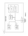
- FIG. 1is a drawing of an exemplary communications system, e.g., a cable network communications system, including fluctuation detection and analysis in accordance with an exemplary embodiment.
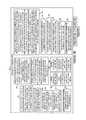
- FIG. 2is a flowchart of an exemplary method of monitoring a communications system in accordance with an exemplary embodiment.
- FIG. 3is a drawing of an exemplary customer premise device in accordance with an exemplary embodiment.
- FIG. 4is drawing of an exemplary network monitoring system in accordance with an exemplary embodiment.
- FIG. 5is an exemplary assembly of modules that may be included in the routines of the memory of exemplary network monitoring system of FIG. 4 .
- FIG. 6illustrates exemplary data/information which may be included in the memory of the exemplary network monitoring system of FIG. 4 .
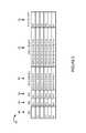
- FIG. 7illustrates an exemplary display corresponding to fluctuation detection and analysis reporting for a plurality of exemplary distribution nodes in an exemplary communications system.
- FIG. 8is a table listing summarized collected and/or processed data corresponding to particular individual customer premise devices.
- FIG. 9is a table listing measurements, time tag information corresponding to the measurements, information identifying the reason the measurements were performed, and an indication as to whether or not there were any detected fluctuation violations for a set of measurements for a particular single customer premise device.
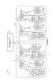
- FIG. 1is a drawing of an exemplary communications system 100 , e.g., a cable network communications system, including fluctuation detection and analysis in accordance with an exemplary embodiment.
- Exemplary communications system 100includes a network monitoring system 102 , a plurality of distribution nodes, and a plurality of customer premise devices.
- exemplary system 100there are a plurality of regions (region 1 152 , . . . , region X 154 .)
- region 1 152there are a plurality of distribution nodes (distribution node 1 104 , . . . , distribution node N 106 ).
- region 1 152there are a plurality of customer premise devices (customer premise device 1 112 , customer premise device 2 114 , . . . , customer premise device Y 116 ) connected to distribution node 1 104 via links ( 158 , 160 , . . . , 162 ), respectively.
- region 1 152there are a plurality of customer premise devices (customer premise device 1 ′ 118 , customer premise device 2 ′ 120 , . . . , customer premise device Z 122 ) connected to distribution node N 106 via links ( 164 , 166 , . . . , 168 ), respectively.
- region X 154there are a plurality of distribution nodes (distribution node 1 ′ 108 , . . . , distribution node M 110 ).
- distribution node 1 ′ 108there are a plurality of customer premise devices (customer premise device 1 ′′ 124 , customer premise device 2 ′′ 126 , . . . , customer premise device V 128 ) connected to distribution node 1 ′ 108 via links ( 170 , 172 , . . . , 174 ), respectively.
- customer premise devicescustomer premise device 1 ′′′ 130 , customer premise device 2 ′′′ 132 , . . .
- the various distribution nodes ( 104 , 106 , 108 , 110 )are coupled to network monitoring system 102 via link 156 .
- One of more customer premise devicesare grouped to the same account.
- a single accountmay correspond to one or more customer premise devices at the same location, e.g., the same house or apartment.
- customer premise device 1 112 and customer premise device 2 114correspond to account 136
- customer premise device Ycorresponds to account 138
- customer premise device 1 ′ 118 and customer premise device 2 ′ 120correspond to account 140
- customer premise device Z 122corresponds to account 142 .
- customer premise device 1 ′′ 124 and customer premise device 2 ′′ 126correspond to account 144 ; customer premise device V 128 corresponds to account 146 ; customer premise device 1 ′′′ 130 and customer premise device 2 ′′′ 132 correspond to account 148 ; and customer premise device W 134 corresponds to account 150 .
- An individual customer premise deviceperforms measurements, e.g., forward data carrier (FDC) and return data carrier (RDC) level measurements, with regard to signals being received from/transmitted to the distribution node to which it is connected.
- FDCforward data carrier
- RDCreturn data carrier
- one or more different types of measurementsare performed in accordance with a schedule, e.g., a predetermined schedule, and/or in response to a command to perform additional diagnostic measurements.
- Measurement data collected by a customer premise devicecorresponding to a plurality of measurement times, is reported to the network monitoring system.
- the network monitoring systemidentifies which customer premise devices are connected to which distribution nodes, and aggregates collected information from the customer premise devices connected to the same distribution node.
- the network monitoring systemgenerates, for each distribution node, a set of data used the evaluate fluctuations.
- Exemplary generated data used to evaluate fluctuationsincludes: the number of fluctuating accounts, the number of fluctuating devices, the fluctuating level, a number of critical violations, a number of warning violations, a percentage of accounts that are fluctuating, a percentage of devices that are fluctuating an a group power level deviation metric, e.g., a modified standard deviation ratio.
- the network monitoring systemidentifies a network distribution node exhibiting high fluctuations and takes an action in response, e.g., commanding diagnostic measurements by the customer premise devices of identified network distribution node, changing the rate of scheduled testing at the customer premise devices of the identified distribution node and/or dispatching a service technician to the identified network distribution node.
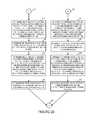
- FIG. 2is a flowchart 200 of an exemplary method of monitoring a communications system, e.g., a cable network communications system, in accordance with an exemplary embodiment.
- Operationstarts in step 202 where the communications system is powered on and initialized. Operation proceeds from start step 202 to steps 204 and 224 .
- a network monitoring systemcollects at least one of transmission power level information or received power level information from a first plurality of customer premise devices. The first plurality of customer premise devices are connected to a first distribution node. Operation proceeds from step 204 to step 206 .
- step 206the network monitoring system generates a first group power level deviation metric, e.g., a modified standard deviation ratio, from collected power level information received from said first plurality of customer premise devices. Then, in step 208 the network monitoring system determines from the collected power level information a number of customer premise devices connected to the first distribution node having detected transmit or receive power level fluctuations over a first threshold, e.g., a warning violation threshold. Operation proceeds from step 208 to step 210 , in which the network monitoring system determines from the collected power level information a number of customer premise devices connected to the first distribution node having transmit or receive power level fluctuations over a second threshold, e.g., a critical violation threshold. Operation proceeds from step 210 , via connecting node A 212 to step 214 .
- a first group power level deviation metrice.g., a modified standard deviation ratio
- step 214the network monitoring system determines the number of fluctuating customer premises devices connected to the first distribution node, the number of fluctuating customer premise devices being a count of devices which had transmit or receive power level fluctuations over said first threshold during a period of time. Operation proceeds from step 214 to step 216 . In step 216 the network monitoring system determines the percentage of customer premise devices connected to the first distribution node which are fluctuating devices. Operation proceeds from step 216 to step 218 . In step 218 the network monitoring system determines the number of fluctuating accounts corresponding to the first distribution node, the number of fluctuating accounts corresponding to the first distribution node being the number of account shaving customer premise devices connected to the first distribution node with detected fluctuations during said period of time. Operation proceeds from step 218 to step 220 . In step 220 the network monitoring system determines the percentage of accounts connected to the first distribution node which are fluctuating accounts.
- step 224the network monitoring system collects at least one of transmission power level information or received power level information from a second plurality of customer premise devices.
- the second plurality of customer premise devicesare connected to a second distribution node. Operation proceeds from step 224 to step 226 .
- step 226the network monitoring system generates second group power level deviation metric, e.g., a modified standard deviation ratio, from collected power level information received from said second plurality of customer premise devices.
- second group power level deviation metrice.g., a modified standard deviation ratio
- step 228the network monitoring system determines from the collected power level information from the second plurality of customer premise devices a number of customer premise devices connected to the second distribution node having detected transmit or receive power level fluctuation over a third threshold, e.g., a warning violation threshold. Operation proceeds from step 228 to step 230 .
- step 230the network monitoring system determines from the collected power level information from the second plurality of customer premise devices a number of customer premise devices connected to the second distribution node having detected transmit or receive power level fluctuations over a fourth threshold, e.g., a critical violation threshold. Operation proceeds from step 230 , via connecting node B 232 , to step 234 .
- step 234the network monitoring system determines the number of fluctuating customer premise devices connected to the second distribution node, the number of fluctuating customer premise devices being a count of customer premise devices connected to the second distribution node which had transmit or received power level fluctuation over said third threshold during said period of time. Operation proceeds from step 234 to step 236 . In step 236 , the network monitoring system determines the percentage of customer premise devices connected to the second distribution node which are fluctuating devices. Operation proceeds from step 236 to step 238 .
- step 238the network monitoring system determines the number of fluctuating accounts corresponding to the second distribution node, the number of fluctuating accounts corresponding to the second distribution node being the number of accounts having customer premise devices connected to the second distribution node with detected fluctuations during said period of time. Operation proceeds from step 238 to step 240 .
- step 240the network monitoring system determines the percentage of accounts connected to the second distribution node which are fluctuating accounts.
- Step 244the network monitoring system takes an action based on one or more generated group power level deviation metrics.
- Step 244includes steps 246 , 254 and 264 .
- step 246the network monitoring system takes an action based on the generated first group power level deviation metric.
- Step 246includes steps 248 , 249 , 250 and 252 . One or more of all of steps 248 , 249 , 250 , and 252 are performed.
- step 248the network monitoring system generates a fluctuation information report based on the first group power level deviation metric.
- step 249the network monitoring system performs at least one of: i) outputting said generated fluctuation information report, of step 248 , to an output device or ii) storing said generated fluctuation information report, of step 248 , on a storage device.
- step 250the network monitoring system dispatches a service technician to service equipment used to communicate signal to or from the first plurality of customer premise devices.
- the network monitoring systemperforms at least one of: i) triggering a network diagnostic operation for, a t least a portion of a network used to transmit to or receive signals from the first plurality of customer premise devices; ii) change the rate at which power level information is collected; or iii) change the number of power level measurements taken during a portion of a day.
- changing the rate at which transmission power level information is collectedincludes changing the rate to perform more measurements per day.
- changing the number of power measurements taken during a portion of a dayincludes increasing the measurements and/or shortening the period between measurements during the period of the day when fluctuations are high, e.g., above a warning or critical threshold.
- step 254the network monitoring system takes an action based on the generated second group power level deviation metric.
- Step 254includes steps 256 , 258 , 260 and 262 . One or more of all of steps 256 , 258 , 260 and 262 are performed.
- step 256the network monitoring system generates a fluctuation information report based on the second group power level deviation metric.
- step 258the network monitoring system performs at least one of: i) outputting said generated fluctuation information report, of step 256 , to an output device or ii) storing said generated fluctuation information report, of step 256 , on a storage device.
- step 260the network monitoring system dispatches a service technician to service equipment used to communicate signal to or from the second plurality of customer premise devices.
- the network monitoring systemperforms at least one of: i) triggering a network diagnostic operation for, at least a portion of a network used to transmit to or receive signals from the second plurality of customer premise devices; ii) change the rate at which power level information is collected with regard to the second plurality of communications devices; or iii) change the number of power level measurements taken during a portion of a day with regard to the second plurality of communications devices.
- step 264the network monitoring system generates a report for a period of time, said report including, on a per node basis, the number of fluctuating customer premise devices corresponding to an individual node, the number of fluctuating accounts corresponding to said individual node, a modified standard deviation ratio corresponding to said individual node, a number of critical violations corresponding to said individual node, a number of warning violations corresponding to said individual node, a percentage of accounts corresponding to said individual node that are fluctuating accounts, and a percentage of fluctuating accounts corresponding to said individual node that are fluctuating devices.
- Flowchart 200 of FIG. 2illustrates exemplary monitoring and actions corresponding to two exemplary distribution nodes.
- the various steps which correspond to the first or second distribution nodemay be performed for other distribution nodes in the system in addition to the first and second distribution node.
- actions in response to a power level deviation metric and/or fluctuation reportingis performed corresponding to the particular distribution nodes in the system which have detected a potential problem but not for the other distribution nodes in the system which have not detected a problem.
- a different distribution node in the systemis the first distribution node and a different distribution node is the second distribution node.
- a customer premise deviceis, e.g., a cable modem or a digital phone.
- a distribution nodeis a Hybrid Fiber-Coaxial (HFC) node.
- the first thresholdis the same as the third threshold and the second threshold is the same as the fourth threshold.
- the first thresholdis different from the third threshold and the second threshold is different from the fourth threshold.
- the first distribution node and the second distribution nodeare subjected to different environmental conditions, e.g., different temperatures and/or temperature variations.
- the first thresholdis different from the third threshold and the second threshold is different from the fourth threshold. In some embodiments, in which the first distribution node and the second distribution nodes correspond to different versions of the same manufacturer, the first threshold is different from the third threshold and the second threshold is different from the fourth threshold.
- a decision to take an actionis based upon at least one group power level deviation metric, e.g., a modified standard deviation ratio, and at least one other value from the set of: number of fluctuating accounts, number of fluctuating devices, FDC fluctuating level, RDC fluctuating level, number of critical violations, number of warning violations, percentage of accounts that are fluctuating, and percentage of devices that are fluctuating, corresponding to the same distribution node.
- group power level deviation metrice.g., a modified standard deviation ratio
- a decision to take an actionis based upon at least one group power level deviation metric, e.g., a modified standard deviation ratio, and at least two values from the set of: number of fluctuating accounts, number of fluctuating devices, FDC fluctuating level, RDC fluctuating level, number of critical violations, number of warning violations, percentage of accounts that are fluctuating, and percentage of devices that are fluctuating, corresponding to the same distribution node.
- group power level deviation metrice.g., a modified standard deviation ratio
- a decision to take an actionis based upon at least one group power level deviation metric, e.g., a modified standard deviation ratio, and at least three values from the set of: number of fluctuating accounts, number of fluctuating devices, FDC fluctuating level, RDC fluctuating level, number of critical violations, number of warning violations, percentage of accounts that are fluctuating, and percentage of devices that are fluctuating, corresponding to the same distribution node.
- group power level deviation metrice.g., a modified standard deviation ratio
- the network monitoring systemdecides whether to automatically assign a service technician to the first distribution node or the second distribution node based on a comparison of the first group power level deviation metric and the second group power level deviation metric, e.g., the technician is assigned to the distribution node having the higher value for its modified standard deviation ratio.
- the network monitoring systemdecides whether to automatically assign a service technician to the first distribution node or the second distribution node based on a comparison of the first group power level deviation metric and the second group power level deviation metric, and based on a comparison of a least one value from the set of: ⁇ number of fluctuating accounts, number of fluctuating devices, FDC fluctuating level, RDC fluctuating level, number of critical violations, number of warning violations, percentage of accounts that are fluctuating, and percentage of devices that are fluctuating ⁇ corresponding to the first distribution node with the same type of at least one value from the set of: ⁇ number of fluctuating accounts, number of fluctuating devices, FDC fluctuating level, RDC fluctuating level, number of critical violations, number of warning violations, percentage of accounts that are fluctuating, and percentage of devices that are fluctuating ⁇ corresponding to the second distribution node.
- FIG. 3is a drawing of an exemplary customer premise device 300 , e.g., a cable modem or digital phone, in accordance with an exemplary embodiment.
- Customer premise deviceis, e.g., and of the customer premise devices of system 100 of FIG. 1 .
- Customer premise device 300includes a receiver module 302 , a transmitter module 304 , an SNR measurement module 306 , a receive power level measurement module 308 , a transmission power determination module 310 , a testing control module 312 , a data collection module 314 , testing information 316 , a testing information updating module 318 , and a power measurement report generation module 320 .
- Testing information 316includes, e.g., testing rate information, testing time information, information identifying which particular measurements are to be performed, information identifying the number of measurements to be performed, testing schedule information.
- the testing information 316is used by the testing control module 312 to generate controls signals ( 350 , 352 , 354 , 356 , 358 , 360 , 362 ) to control the operation of the various modules ( 302 , 304 , 306 , 308 , 310 , 314 , 320 ), respectively.
- the testing control modulemay control the implementation of multiple tests according to a schedule, in many embodiments the testing control module responds to instructions and/or requests that specific tests be performed with the test results then being sent to the transmitter module for reporting to the network monitoring system, e.g., server.
- the network monitoring systemcan control the scheduling, times, and/or rate of such tests by sending out SNMP requests for transmit, receive and/or SNR level information in accordance with the desired schedule, times and/or rate at which such information is to be collected from a device.
- the network monitoring systemcontrols the polling of the customer premise devices avoiding the customer premise devices having to collect and aggregate power measurements over an extended time period, e.g., hours or days according to a schedule stored in or supplied to the customer premise device.
- an extended time periode.g., hours or days according to a schedule stored in or supplied to the customer premise device.
- whether the aggregation and storage of multiple power level measurements occurs in the customer premise device and are reported up to the network monitoring system in a single message or test results corresponding to each individual time period are sent separatelymay depend on the particular embodiment and/or the capabilities of the customer premise devices.
- the polling rate and/or tests performed by the individual customer premise devicesis controlled by the network monitoring system and can be changed in response to detection of power fluctuation levels exceeding one or more thresholds and/or as part of automatically triggered diagnostic process with the customer premise device responding to poll requests with the requested transmit, receive and/or SNR level information.
- Transmission power level determination module 310determines the transmission power level of signals transmitted by transmitter module 304 .
- Signal 332generated by transmission power determination module 310 conveys the determined TX power level value to data collection module 314 .
- Receive power level measurement module 308measures the received power of received signal 322 received by receiver module 302 .
- Signal 328generated by receive module 310 conveys the determined RX power level value to data collection module 314 .
- SNR measurement module 306determines an SNR level based on received signals 324 which includes received test signaling 324 .
- Signal 330generated by SNR measurement module 306 conveys the determined SNR value to data collection module 314 .
- Data collection module 314collects the data and forms a data set, e.g., including a FDC value, a RDC value, and an SNR value. Data collection module 314 sends the data set 334 to power measurements report generation module 320 . The data collection process is performed a number of times under the control of the testing control module based on the testing information 316 .
- Power report generation module 320generates a report 336 directed to the network monitoring system including collected sets corresponding to a plurality of different times.
- the power report generation module 320also adds time tag information corresponding to the data sets and information identifying the reason that the testing was performed for each set of data in the report.
- Drawing 700illustrates exemplary data communicated in report 336 .
- Report 336is transmitted by transmitter module 336 and routed to the network monitoring system, e.g., network monitoring system 102 of system 100 of FIG. 1 .
- Customer premise device 300may, and sometimes does, receive a signal 338 from the network monitoring system commanding a change in the testing.
- Testing information updating module 318receives, via receiver module 302 , command signal 338 and updates the testing information 316 in response to the received command signal 338 .
- Testing control module 312implements the change in testing.
- Various exemplary commandsinclude a diagnostic test operation, a change in the rate at which power level information is collected, and a change in the number of power measurements taken during a portion of a day.
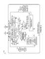
- FIG. 4is drawing of an exemplary network monitoring system 400 , e.g., a network monitoring node, in accordance with an exemplary embodiment.
- Network monitoring system 400is, e.g., network monitoring system 102 of communications system 100 of FIG. 1 .
- Network monitoring system 400includes an output device 402 , e.g., a display, an input device 404 , e.g., a keyboard, a processor 406 , e.g., a CPU, an I/O interface 408 , and memory 410 .
- the various elements ( 402 , 404 , 406 , 408 , 410 )are coupled together via a bus 411 over which the various elements may exchange data and information.
- Memory 410includes routines 412 and data/information 414 .
- the processor 406executes the routines 412 and uses the data/information 414 in memory 410 to control the network monitoring system and implement steps of a method, e.g., the method of flowchart 200 of FIG. 2 .
- FIG. 5is an assembly of modules 500 , comprising the combination of part A 501 and part B 503 .
- the assembly of modules 500is, e.g., included in routines 412 of memory 410 of network monitoring system 400 of FIG. 4 .
- Assembly of modules 500includes a module 502 configured to receive a power level information report from a customer premise device, a module 504 configured to identify which customer premise devices correspond to the same account, a module 506 configured to identify which customer premise devices are connected to a distribution node, a module 508 , e.g., a collection module, configured to collect power level information form a plurality of customer premise devices connected to a distribution node, a module 510 configured to generate a modified standard deviation corresponding to a customer premise device.
- a module 502configured to receive a power level information report from a customer premise device
- a module 504configured to identify which customer premise devices correspond to the same account
- a module 506configured to identify which customer premise devices are connected to a distribution node
- a module 508e.g., a collection module, configured to collect power level information form a plurality of customer premise devices connected to a distribution node
- a module 510configured to generate a modified standard
- Assembly of modules 500further includes a module 512 , e.g., a first group power level deviation metric generation module, configured to generate a group power level deviation metric, e.g., a modified standard deviation ratio, corresponding to a distribution node, a module 514 , e.g., a first customer premise device determination module, configured to determine the number of customer premise devices connected to a distribution node having detected transmit or receive power level fluctuations above a warning threshold, a module 516 , e.g., a second customer premise number determination module, configured to determine the number of customer premise devices connected to a distribution node having detected transmit or receive power level fluctuations above a critical threshold, a module 518 , e.g., a third customer premise number determination module, configured to determine the number of fluctuating customer premise devices connected to a distribution node, a module 520 configured to determine the percentage of customer premise devices connected to a distribution node which are fluctuating devices, a module 522 configured to determine the number
- Assembly of modules 500further includes a module 530 configured to decide which distribution node or nodes an action is to be taken on based on generated group power level deviation metrics corresponding to different distribution nodes, a module 532 configured to take an action based on a generated power level deviation metric, a module 534 , e.g., a report generation module, configured to generate a fluctuation information report based on a group level power deviation metric, a module 536 , e.g., an output module, configured to output a generated fluctuation information report to an output device, and a module 538 , e.g., a report storage module, configured to store a generated fluctuation information report on a storage device.
- a module 530configured to decide which distribution node or nodes an action is to be taken on based on generated group power level deviation metrics corresponding to different distribution nodes
- a module 532configured to take an action based on a generated power level deviation metric
- a module 534e.g., a report
- Assembly of modules 500further includes a module 540 , e.g., an automatic service dispatch module, configured to dispatch a service technician to service equipment used to communicate signals to or from a plurality of customer premise devices corresponding to a particular distribution node based on a group level power deviation metric.
- a module 540e.g., an automatic service dispatch module, configured to dispatch a service technician to service equipment used to communicate signals to or from a plurality of customer premise devices corresponding to a particular distribution node based on a group level power deviation metric.
- Assembly of modules 500further includes a module 542 configured to trigger a network diagnostic operation for at least a portion of a network used to transmit or receive signals from a plurality of customer premise devices corresponding to a distribution node based on a generated group power level deviation metric, a module 544 configured to change the rate at which power level information is collected based on a generated group power level deviation metric, and a module 546 configured to change the number of power measurements taken during a portion of a day based on a generated group power level deviation metric.
- Assembly of modules 500further includes a module 548 configured to generate a summary fluctuation information report for a period of time, said report including, on a per distribution node basis, the number of fluctuation customer premise devices corresponding to an individual node, the number of fluctuating accounts corresponding to said individual node, a modified standard deviation ratio corresponding to said individual node, a number of critical violations corresponding to said individual node, a number of warning violations corresponding to said individual node, a percentage of accounts corresponding to said individual node which are fluctuating accounts and a percentage of customer premise devices corresponding to said individual node which are fluctuating devices.
- Assembly of modules 500further includes a module 550 configured to output a generated summary report to an output device and a module 552 configured to store a generated summary report to a storage device.
- Assembly of modules 500further includes a module 560 configured to generate a map including power fluctuation information, a module 562 configured to output a generated map included power fluctuation information to an output device, e.g., a display, and a module 564 configured to output a generated map including power fluctuation information to a storage device.
- the generated mapis, e.g., a map including distribution nodes and communications links with the power fluctuation information overlaid on the map to facilitate the identification of potential points of failure.
- the power fluctuation informationmay be indicated using text, symbols, highlighting, and/or different coloring. In some embodiments, distribution nodes experiencing critical fluctuations may be identified in red and distribution nodes experiencing warning fluctuations may be identified in yellow.
- module 530uses input from additional group level fluctuation parameters when deciding which node or nodes an action is to be taken on. For example, in addition to basing its decision on a modified standard deviation ratio, module 530 uses input from one or more or all: the number of fluctuating devices, the number of fluctuating accounts, the percentage of fluctuating devices, the percentage of fluctuating accounts, fluctuating level information for RDC, fluctuating level information for FDC, number of critical violations, and number of warning violations.
- module 508performs steps 204 and 224 of flowchart 200 ; module 512 performs steps 206 and 226 of flowchart 200 ; module 514 performs steps 208 and 228 of flowchart 200 ; module 516 performs steps 210 and 230 of flowchart 200 ; module 518 performs steps 214 and 234 of flowchart 200 ; module 520 performs steps 216 and 236 of flowchart 200 ; module 520 performs steps 522 performs steps 218 and 236 of flowchart 200 ; module 524 performs steps 220 and 240 of flowchart 200 ; module 532 performs steps 224 , 246 and 254 of flowchart 200 ; module 534 performs steps 248 and 256 of flowchart 200 ; module 536 performs a portion of step 249 and 258 of flowchart 200 ; module 538 performs a portion of step 249 and 258 of flowchart 200 ; module 540 performs step 250 and 260 of flowchart 200 ; module
- Module 508e.g., a collection module is configured to collect at least one of transmission power level information or received power level information from a first plurality of customer premise devices.
- Module 512e.g., a first group power level deviation metric generation module, is configured to generate a first group power level deviation metric from collected power level information received from said first plurality of customer premise devices.
- One or more of modules 532 , 534 , 536 , 538 or 540e.g., action modules, are configured to take an action based on the generated first group power level deviation metric.
- Module 534e.g., a report generation module, is configured to generate a fluctuation information report based on said first group power level deviation metric.
- Module 536e.g., an output module
- Module 538e.g., a report storage module
- Module 540e.g., an automatic service dispatch module, is configured to automatically dispatch a service technician to service equipment used to communicate signals to or from said first plurality of customer premise devices.
- taking an actionincludes at least one of: i) triggering a network diagnostic operation for at least a portion of a network used to transmit to or receive signals from the first plurality of customer premise devices; ii) changing the rate, e.g., more measurements per day, at which power level information is collected; or iii) changing a number of power measurements taken during a portion of a day, e.g., increase the number of measurements/shorten the period between measurements during a period of a day in which fluctuations are high, e.g., above a warning or critical threshold.
- the first plurality of customer premise devicesare connected to a first distribution node, and module 514 , e.g., a first customer premise device determination module, is configured to determine from the collected power level information a number of customer premise devices connected to the first distribution node having detected transmit or receive power level fluctuations over a first threshold, e.g., a warning violation threshold.
- a first thresholde.g., a warning violation threshold.
- the first plurality of customer premise devicesare connected to a first distribution node, and module 516 , e.g., a second customer premise number determination module, is configured to determine from the collected power level information a number of customer premise devices connected to the first distribution node having a detected transmit or receive power level fluctuations over a second threshold, e.g., a critical violation threshold.
- a second thresholde.g., a critical violation threshold
- the first plurality of customer premise devicesare connected to a first distribution node, and module 518 , e.g., a third customer premise number determination module, is configured to determine from the collected power level information a number of fluctuating customer premise devices connected to the first distribution node, the number of fluctuating devices being a count of the number of devices which had transmit or receive power level fluctuation over said threshold during a period of time.
- module 518e.g., a third customer premise number determination module, is configured to determine from the collected power level information a number of fluctuating customer premise devices connected to the first distribution node, the number of fluctuating devices being a count of the number of devices which had transmit or receive power level fluctuation over said threshold during a period of time.
- FIG. 6is a drawing of data/information 600 in accordance with an exemplary embodiment.
- Data/information 600is, e.g., included in data/information 414 of network monitoring system 400 of FIG. 4 .
- Data/information 600includes network topology information 602 , e.g., information identifying which customer devices are connected to which network distribution nodes and information indicating which devices and nodes are located in which regions of the system.
- Data/information 600also includes account information 604 , e.g., information associating a set of one or more customer premise devices with a customer account, e.g., a customer account corresponding to a particular location.
- Data/information 600includes a plurality of received power information reports from a plurality of customer premise devices (received power information report from customer premise device 1 606 , . . . , received power information report from customer premise device U 608 ). Data/information also includes generated modified standard deviation(s) corresponding to each of the received reports from the customer premise devices (generated modified standard deviation(s) corresponding to customer premise device 1 610 , . . . , generated modified standard deviation(s) corresponding to customer premise device U 612 ).
- One exemplary received power information report from a customer premise deviceis, e.g., a set of 12 pairs of data measurements of an FDC level and an RDC level with corresponding time tag information indicating when the measurements were performed. In one embodiments, the measurements correspond to 3 days with 4 pairs of measurements per day with the measurement pairs being approximately evenly spaced in time, e.g., a pair of measurements being taken by the customer premise device once every eight hours.
- Data/information 600also includes a generated group power level deviation metric, e.g., a modified standard deviation ratio, corresponding to each distribution node (generated group power level deviation metric, e.g., modified standard deviation ratio, corresponding to distribution node 1 614 , . . . , generated group power level deviation metric, e.g., modified standard deviation ratio, corresponding to distribution node T 618 ).
- Data/information 600also includes a fluctuation information report corresponding to each distribution node (generated fluctuation information report corresponding to distribution node 1 616 , . . . , generated fluctuation information report corresponding to distribution node T 620 .)
- Data/information 600further includes information 622 identifying the determined distribution node or nodes for which action is to be taken based on the generated group power level deviation metrics.
- Data/information 600further includes a generated service technician dispatch signal 624 to direct the technician to a suspected problem area, a generated signal to trigger diagnostic operation on a portion of the network 626 , a generated signal to change the rate at which power level information is collected on a set of customer premise devices corresponding to an identified distribution node 628 , a generated signal to change the number of power level measurements taken during a portion of a day in a set of customer premise devices corresponding to an identified distribution node 630 and a generated summary fluctuation report 632 .
- Network topology information 602is used by module 506 and module 542 .
- Account information 604is used by module 504 .
- Received reports ( 606 , . . . , 608 )are received by module 502 .
- Generated modified standard deviation(s) ( 610 , . . . , 612 )are generated by module 510 from information included in received reports ( 606 , . . . , 608 ), respectively, using weighting information 634 .
- Generated group power level deviation metrics ( 614 , . . . , 618 )are generated by module 512 .
- Generated fluctuation information reports ( 616 , . . . , 620are generated by module 534 .
- Dispatch signal 624is generated and output by module 540 .
- Diagnostic signal 626is generated and output by module 542 .
- Change signal 628is generated and output by module 544 .
- Change signal 630is generated and output by module 630 .
- Generated summary fluctuation information report 632is generated by module 548 , output by module 550 and stored by module 552 .
- the concept behind the fluctuation reportis to implement an advanced telemetry analysis routine that analyzes variation within a given metric over a sequential number of data points, and then aggregates those fluctuations up to a common analysis point. That aggregation point is then analyzed across a number of metrics to determine a relative degree of instability to aid in the dispatch and efficiency of problem resolution.
- This logiccould apply to any metric that was received over a sequence of data points to detect unacceptable levels of inconsistency.
- Telecommunications and multiple system operator (MSO) servicescould benefit from this technology.
- Various embodiments of the inventionaddress the problem of a lack of functionality in current metric analysis and signal level diagnosis systems. Some current metric analysis systems only check a parameter against a simple threshold, and do not diagnose instability over time. Various embodiments, of the current invention are directed to diagnosing instability over time.
- Various embodiments of the current inventionmeasure a significant number of polls over a longer period and use a calculation to determine the impact and degree of the instability over a set of sets.
- data corresponding to many devices over many metricsis collected, analyzed and used in making decisions.
- the concept behind the fluctuation reportis to implement an advanced telemetry analysis routine that analyzes variation within a given metric over a sequential number of data points, and then aggregates those fluctuations up to a common analysis point. That aggregation point is then analyzed across a number of metrics to determine a relative degree of instability to aid in the dispatch and efficiency of problem resolution.
- a basic example of this processis outlined below.
- SNMPSimple Network Management Protocol
- the Transmit and Receive of the Cable Modemis polled 12 times over the course of 3 days, or 4 times a day.
- the datais collected by the modem and communicated to the network monitoring system, e.g., in a report including the measurements and corresponding time tag information.
- the data collectionresults in a set of data points like the data set shown below.
- time tag information corresponding to measurementsis implicit and is not necessarily communicated directly in the report to the network monitoring system.
- the data shown belowrepresents a sequence of poll results from earliest to latest.
- the standard deviation calculationscan be performed by the modem and reported to the network monitoring system or calculated directly by the network monitoring system.
- a measure of instability for the purposes of one Cable Modemhas been obtained.
- it is advantageous to aggregate and compare the overall number of devices and their individual level fluctuationse.g., to identify plant impairments such as a problem at a particular distribution node connected to a specific set of customer premise devices.
- a network monitoring systemperforms the following calculations once the standard deviations have been calculated per Cable Modem Per Metric:
- the network monitoring systemFor each of the metrics per modem in a given area, in this case a Hybrid Fiber-Coaxial (HFC) node, the network monitoring system creates a sum total of each of the standard deviations.
- HFCHybrid Fiber-Coaxial
- the system as implementedallows for weighting of individual metrics and degrees of fluctuation. So if the business organization identifies that the Receive metric is inherently more critical and requires more stability, the individual modem standard deviation calculation can be, and in some embodiments, is modified by a weight some percentage. In some embodiments, the network monitoring system implements the identified weighting.
- the system as implementedallows for weighting for degree of fluctuation beyond a set threshold. So if the metric of Receive was defined as having allowable upper levels of 7 or below and lower levels of 3 or greater, the weighting system could, and in some embodiments, does add an additional fluctuation penalty for any data point outside that range. So in the above example a level that was 1 point above the upper threshold could be increased by a multiplier to indicate additional severity. That would result in the below transformation:
- Modified Standard DeviationThis new measurement is referred to as “Modified Standard Deviation”.
- a modified standard deviation for receive for a customer premise deviceis calculated and a modified standard deviation for transmit is calculated for the same customer premise device.
- a single modified standard deviation for the customer premise devicee.g., modem, is calculated, e.g., the average of the modified standard deviation for receive and the modified standard deviation for transmit.
- the network monitoring systemcalculates a modified standard deviation ratio for a network distribution node. For example, if there are a plurality of customer premise devices connected to the same distribution node, in one embodiment, the modified standard deviation ratio for the distribution node is calculated from averaging the modified standard deviation ratios from each of the plurality of customer premise devices connected to the distribution node. In some embodiments, separate modified standard deviation ratios are determined for a distribution mode for receive and for transmit. In some embodiments, a single modified standard deviation ratio is determined for a network distribution node. In some embodiments, in determining a single modified standard deviation ratio for a distribution node equal weighting is given to transmit and receive. In some embodiments, in determining a single modified standard deviation ratio for a distribution node different weightings are given to transmit and receive.
- This modified standard deviation ratio metricis used by the network monitoring system to compare areas of service, e.g., in a Cable Plant or region or within the network, based upon both degree of fluctuation and breadth of fluctuation.
- the network monitoring systemdirects resources at those areas expected to have the largest degree of impact over the largest collection of subscribers based on the calculated modified standard deviation ratios.
- the modified standard deviation ratio for a distribution nodeis a sum of each of the modified standard deviations for each of the metrics, e.g., modified standard deviation for receive and modified standard deviation for transmit, from each of the customer premise devices connected to the distribution node, divided by the total number of customer premise devices connected to the distribution node.
- First column 702identifies a plurality of nodes, e.g., distribution nodes, being monitored.
- Second column 704includes the number of fluctuating accounts corresponding to each node.
- the number of fluctuating accountsrepresent the number of accounts corresponding to the node that showed fluctuation over two subsequent test measurements, e.g., two subsequent polls, wherein the fluctuation was high enough to trigger a warning violation or critical violation.
- Third column 706includes the number of fluctuating devices corresponding to each node, e.g., distribution node.
- the number of fluctuating devicesrepresent the number of customer premise devices corresponding to the node that showed fluctuation over two subsequent test measurements, e.g., two subsequent polls, wherein the fluctuation was high enough to trigger a warning violation or critical violation.
- Fourth column 708includes the fluctuating levels for two signal levels, the FDC (receive) and RDC (transmit), with regard to the customer premise devices corresponding to each node. Fluctuating level represents a percentage of the detected device fluctuations, which include detected warning and critical fluctuations, observed during a data window.
- the Fifth column 710includes a modified standard deviation ratio corresponding to each of the nodes, e.g., distribution nodes.
- the modified standard deviation ratio for a distribution nodeis a sum of the modified standard deviations generated for each of the devices corresponding to the distribution node divided by a number which is equal to or based on the number of devices corresponding to the distribution node.
- the summay include multiple modified standard deviations corresponding to a single device, e.g., a modified standard deviation for receive for a modem and a modified standard deviation for transmit for the modem.
- the modified standard deviation ratio fieldallows one to determine whether the fluctuation across multiple customer premise devices is consistent or caused by a one-time spike. In this field the higher the number for the modified standard deviation ratio, the more endemic fluctuation corresponding to the node.
- some actionis taken for distribution nodes with high modified standard deviation ratios, e.g., above a predetermined limit. In various embodiments, different actions are taken for different distribution nodes with modified standard deviation ratios exceeding different predetermined limits.
- exceeding a first levelresults in the generation and storage and/or display of a fluctuation level report
- exceeding a second levelresults in the commanding a change to the regularly scheduled testing
- exceeding a third levelresults in commanding diagnostic testing
- exceeding a fourth levelresults in automatically dispatching a service technician to the node.
- the nodes with the higher modified standard deviation ratiosget attention before the nodes with the lower modified standard deviation ratios.
- Sixth column 712includes the number of critical violations corresponding to each of the nodes.
- the number of critical violationsis a raw count of how many times a signal level fluctuated greater than a critical threshold during a data window.
- the critical thresholdis 12 dB. Both changes in FDC and changes in RDC measurements are evaluated in determining the number of critical violations.
- Seventh column 714includes the number of warning violations corresponding to each of the nodes.
- a warning violationis a violation above a warning violation threshold of 6 dB and is less than a critical violation.
- the number of warning violationsis raw count of how many times a signal level fluctuated by at least 6dBs and up to and including but not greater than 12dBs during a data window. Both changes in FDC and changes in RDC measurements are evaluated in determining the number of warning violations. In some embodiments, there are different warning violation thresholds used for RDC and FDC.
- Eighth column 716includes the percentage of accounts that are fluctuating corresponding to each of the nodes.
- Ninth column 718includes a percentage of customer premise devices that are fluctuating corresponding to each of the nodes.
- Drawing 800 of FIG. 8illustrates an exemplary Node Flux report which provides a view of fluctuating customer premise devices corresponding to a distribution node.
- First column 802identifies particular devices and corresponding MAC addresses.
- Second column 804includes account information corresponding to each of the devices.
- Third column 806includes address information corresponding to each of the devices.
- Fourth column 808identifies the signal type for which at least one violation has been detected, e.g., Forward Data Carrier (FDC) or Return Data Carrier (RDC).
- Fifth column 810includes a count of the number of warning violations corresponding to each device and corresponding signal type.
- Sixth column 812includes the number of critical violations corresponding to each device and signal type.
- Seventh column 814includes a standard deviation corresponding to each device and signal type which has been identified as having at least one violation.
- First column 902includes Forward Data Carrier (FDC) measurement level values.
- the forward data carrier level valuerefers to the receive level of signals at the customer premise device which is receiving signals from a distribution node to which it is connected.
- the second column 904includes Return Data Carrier (RDC) measurement level values.
- the return data carrier level valuerefers to the transmit level of signals at the customer premise device which is transmitting to a distribution node to which it is connected.
- Third column 906includes signal to noise ratio (SNR) measurement values.
- Fourth column 908identifies when the measurements were performed.
- Fifth column 910identifies the reason that the check was performed, e.g., as part of a scheduled interval signal level poll, or as part of a network diagnostic operation in response to a detected problem.
- Six column 912indicates whether or not any fluctuation violations were detected.
- each stepmay be performed by one or more different software instructions executed by a computer processor, e.g., a central processing unit (CPU).
- a computer processore.g., a central processing unit (CPU).
- CPUcentral processing unit
- At least one system implemented in accordance with the present inventionincludes a means for implementing each of the various steps which are part of the methods of the present invention.
- Each meansmay be, e.g., an instruction, processor, hardware circuit and/or combination of elements used to implement a described step.
- machinee.g., computer, executable instructions, such as software, included in a non-transitory machine, e.g., computer, readable medium used to control a machine, e.g., general purpose computer with or without additional hardware, to implement all or portions of the above described methods, e.g., in one or more nodes.
- the machine readable mediummay be, e.g., a memory device, e.g., RAM, floppy disk, etc.
- the present inventionis directed to a machine-readable medium including machine executable instructions for causing a machine, e.g., processor and associated hardware, to perform one or more of the steps of the above-described method(s).
Landscapes
- Engineering & Computer Science (AREA)
- Computer Networks & Wireless Communication (AREA)
- Signal Processing (AREA)
- Computer Security & Cryptography (AREA)
- Environmental & Geological Engineering (AREA)
- Remote Monitoring And Control Of Power-Distribution Networks (AREA)
Abstract
Description
Claims (20)
Priority Applications (2)
| Application Number | Priority Date | Filing Date | Title |
|---|---|---|---|
| US13/468,564US9143379B1 (en) | 2012-05-01 | 2012-05-10 | Power fluctuation detection and analysis |
| US14/831,786US9686166B2 (en) | 2012-05-01 | 2015-08-20 | Power fluctuation detection and analysis |
Applications Claiming Priority (2)
| Application Number | Priority Date | Filing Date | Title |
|---|---|---|---|
| US201261641295P | 2012-05-01 | 2012-05-01 | |
| US13/468,564US9143379B1 (en) | 2012-05-01 | 2012-05-10 | Power fluctuation detection and analysis |
Related Child Applications (1)
| Application Number | Title | Priority Date | Filing Date |
|---|---|---|---|
| US14/831,786ContinuationUS9686166B2 (en) | 2012-05-01 | 2015-08-20 | Power fluctuation detection and analysis |
Publications (1)
| Publication Number | Publication Date |
|---|---|
| US9143379B1true US9143379B1 (en) | 2015-09-22 |
Family
ID=54107180
Family Applications (2)
| Application Number | Title | Priority Date | Filing Date |
|---|---|---|---|
| US13/468,564Active2033-06-29US9143379B1 (en) | 2012-05-01 | 2012-05-10 | Power fluctuation detection and analysis |
| US14/831,786Active2032-10-18US9686166B2 (en) | 2012-05-01 | 2015-08-20 | Power fluctuation detection and analysis |
Family Applications After (1)
| Application Number | Title | Priority Date | Filing Date |
|---|---|---|---|
| US14/831,786Active2032-10-18US9686166B2 (en) | 2012-05-01 | 2015-08-20 | Power fluctuation detection and analysis |
Country Status (1)
| Country | Link |
|---|---|
| US (2) | US9143379B1 (en) |
Cited By (47)
| Publication number | Priority date | Publication date | Assignee | Title |
|---|---|---|---|---|
| US10318401B2 (en)* | 2017-04-20 | 2019-06-11 | Qumulo, Inc. | Triggering the increased collection and distribution of monitoring information in a distributed processing system |
| US10459892B2 (en) | 2014-04-23 | 2019-10-29 | Qumulo, Inc. | Filesystem hierarchical aggregate metrics |
| US10491632B1 (en)* | 2016-01-21 | 2019-11-26 | F5 Networks, Inc. | Methods for reducing compliance violations in mobile application management environments and devices thereof |
| US10614033B1 (en) | 2019-01-30 | 2020-04-07 | Qumulo, Inc. | Client aware pre-fetch policy scoring system |
| US10725977B1 (en) | 2019-10-21 | 2020-07-28 | Qumulo, Inc. | Managing file system state during replication jobs |
| US10795796B1 (en) | 2020-01-24 | 2020-10-06 | Qumulo, Inc. | Predictive performance analysis for file systems |
| US10860372B1 (en) | 2020-01-24 | 2020-12-08 | Qumulo, Inc. | Managing throughput fairness and quality of service in file systems |
| US10860414B1 (en) | 2020-01-31 | 2020-12-08 | Qumulo, Inc. | Change notification in distributed file systems |
| US10877942B2 (en) | 2015-06-17 | 2020-12-29 | Qumulo, Inc. | Filesystem capacity and performance metrics and visualizations |
| US10936538B1 (en) | 2020-03-30 | 2021-03-02 | Qumulo, Inc. | Fair sampling of alternate data stream metrics for file systems |
| US10936551B1 (en) | 2020-03-30 | 2021-03-02 | Qumulo, Inc. | Aggregating alternate data stream metrics for file systems |
| CN112508450A (en)* | 2020-12-22 | 2021-03-16 | 国网上海市电力公司 | Method for evaluating acceptance capability of urban power distribution network to electric automobile |
| US11122042B1 (en) | 2017-05-12 | 2021-09-14 | F5 Networks, Inc. | Methods for dynamically managing user access control and devices thereof |
| US11132126B1 (en) | 2021-03-16 | 2021-09-28 | Qumulo, Inc. | Backup services for distributed file systems in cloud computing environments |
| US11132336B2 (en) | 2015-01-12 | 2021-09-28 | Qumulo, Inc. | Filesystem hierarchical capacity quantity and aggregate metrics |
| US11151092B2 (en) | 2019-01-30 | 2021-10-19 | Qumulo, Inc. | Data replication in distributed file systems |
| US11151001B2 (en) | 2020-01-28 | 2021-10-19 | Qumulo, Inc. | Recovery checkpoints for distributed file systems |
| US11157458B1 (en) | 2021-01-28 | 2021-10-26 | Qumulo, Inc. | Replicating files in distributed file systems using object-based data storage |
| US11178150B1 (en) | 2016-01-20 | 2021-11-16 | F5 Networks, Inc. | Methods for enforcing access control list based on managed application and devices thereof |
| US11256682B2 (en) | 2016-12-09 | 2022-02-22 | Qumulo, Inc. | Managing storage quotas in a shared storage system |
| US11294604B1 (en) | 2021-10-22 | 2022-04-05 | Qumulo, Inc. | Serverless disk drives based on cloud storage |
| US11343237B1 (en) | 2017-05-12 | 2022-05-24 | F5, Inc. | Methods for managing a federated identity environment using security and access control data and devices thereof |
| US11347699B2 (en) | 2018-12-20 | 2022-05-31 | Qumulo, Inc. | File system cache tiers |
| US11350254B1 (en) | 2015-05-05 | 2022-05-31 | F5, Inc. | Methods for enforcing compliance policies and devices thereof |
| US11354273B1 (en) | 2021-11-18 | 2022-06-07 | Qumulo, Inc. | Managing usable storage space in distributed file systems |
| US11360936B2 (en) | 2018-06-08 | 2022-06-14 | Qumulo, Inc. | Managing per object snapshot coverage in filesystems |
| US11425017B2 (en)* | 2020-05-20 | 2022-08-23 | Verizon Patent And Licensing Inc. | Systems and methods for utilizing a neural network model to perform packet capture data analysis |
| US11425019B2 (en)* | 2017-10-02 | 2022-08-23 | Salesforce.Com, Inc. | Inspecting network performance at diagnosis points |
| US11461241B2 (en) | 2021-03-03 | 2022-10-04 | Qumulo, Inc. | Storage tier management for file systems |
| CN115356592A (en)* | 2022-08-29 | 2022-11-18 | 南京乾鑫电器设备有限公司 | Novel fault monitoring method and system for low-voltage distribution equipment |
| US11567660B2 (en) | 2021-03-16 | 2023-01-31 | Qumulo, Inc. | Managing cloud storage for distributed file systems |
| US11599508B1 (en) | 2022-01-31 | 2023-03-07 | Qumulo, Inc. | Integrating distributed file systems with object stores |
| US11669255B2 (en) | 2021-06-30 | 2023-06-06 | Qumulo, Inc. | Distributed resource caching by reallocation of storage caching using tokens and agents with non-depleted cache allocations |
| US11722150B1 (en) | 2022-09-28 | 2023-08-08 | Qumulo, Inc. | Error resistant write-ahead log |
| US11729269B1 (en) | 2022-10-26 | 2023-08-15 | Qumulo, Inc. | Bandwidth management in distributed file systems |
| US11757946B1 (en) | 2015-12-22 | 2023-09-12 | F5, Inc. | Methods for analyzing network traffic and enforcing network policies and devices thereof |
| US11775481B2 (en) | 2020-09-30 | 2023-10-03 | Qumulo, Inc. | User interfaces for managing distributed file systems |
| US11921677B1 (en) | 2023-11-07 | 2024-03-05 | Qumulo, Inc. | Sharing namespaces across file system clusters |
| US11934660B1 (en) | 2023-11-07 | 2024-03-19 | Qumulo, Inc. | Tiered data storage with ephemeral and persistent tiers |
| US11966592B1 (en) | 2022-11-29 | 2024-04-23 | Qumulo, Inc. | In-place erasure code transcoding for distributed file systems |
| CN118735659A (en)* | 2024-09-03 | 2024-10-01 | 江西省博信玻璃有限公司 | A production scheduling method and system based on big data technology |
| CN119070488A (en)* | 2024-11-05 | 2024-12-03 | 国网浙江省电力有限公司杭州市余杭区供电公司 | A method for identifying weak links in distribution networks with renewable energy access |
| US12222903B1 (en) | 2024-08-09 | 2025-02-11 | Qumulo, Inc. | Global namespaces for distributed file systems |
| US12292853B1 (en) | 2023-11-06 | 2025-05-06 | Qumulo, Inc. | Object-based storage with garbage collection and data consolidation |
| CN120013702A (en)* | 2025-04-17 | 2025-05-16 | 福建威而特旋压科技有限公司 | A production process traceability method for a hub transmission device |
| US12346290B2 (en) | 2022-07-13 | 2025-07-01 | Qumulo, Inc. | Workload allocation for file system maintenance |
| US12443559B2 (en) | 2025-04-18 | 2025-10-14 | Qumulo, Inc. | Object-based storage with garbage collection and data consolidation |
Families Citing this family (193)
| Publication number | Priority date | Publication date | Assignee | Title |
|---|---|---|---|---|
| US9859757B1 (en) | 2013-07-25 | 2018-01-02 | Energous Corporation | Antenna tile arrangements in electronic device enclosures |
| US10992185B2 (en) | 2012-07-06 | 2021-04-27 | Energous Corporation | Systems and methods of using electromagnetic waves to wirelessly deliver power to game controllers |
| US10128693B2 (en) | 2014-07-14 | 2018-11-13 | Energous Corporation | System and method for providing health safety in a wireless power transmission system |
| US9941754B2 (en) | 2012-07-06 | 2018-04-10 | Energous Corporation | Wireless power transmission with selective range |
| US9893555B1 (en) | 2013-10-10 | 2018-02-13 | Energous Corporation | Wireless charging of tools using a toolbox transmitter |
| US20150326070A1 (en) | 2014-05-07 | 2015-11-12 | Energous Corporation | Methods and Systems for Maximum Power Point Transfer in Receivers |
| US10090699B1 (en) | 2013-11-01 | 2018-10-02 | Energous Corporation | Wireless powered house |
| US10063105B2 (en) | 2013-07-11 | 2018-08-28 | Energous Corporation | Proximity transmitters for wireless power charging systems |
| US9438045B1 (en) | 2013-05-10 | 2016-09-06 | Energous Corporation | Methods and systems for maximum power point transfer in receivers |
| US9893768B2 (en) | 2012-07-06 | 2018-02-13 | Energous Corporation | Methodology for multiple pocket-forming |
| US9853692B1 (en) | 2014-05-23 | 2017-12-26 | Energous Corporation | Systems and methods for wireless power transmission |
| US10256657B2 (en) | 2015-12-24 | 2019-04-09 | Energous Corporation | Antenna having coaxial structure for near field wireless power charging |
| US10211680B2 (en) | 2013-07-19 | 2019-02-19 | Energous Corporation | Method for 3 dimensional pocket-forming |
| US9973021B2 (en) | 2012-07-06 | 2018-05-15 | Energous Corporation | Receivers for wireless power transmission |
| US9825674B1 (en) | 2014-05-23 | 2017-11-21 | Energous Corporation | Enhanced transmitter that selects configurations of antenna elements for performing wireless power transmission and receiving functions |
| US10263432B1 (en) | 2013-06-25 | 2019-04-16 | Energous Corporation | Multi-mode transmitter with an antenna array for delivering wireless power and providing Wi-Fi access |
| US11502551B2 (en) | 2012-07-06 | 2022-11-15 | Energous Corporation | Wirelessly charging multiple wireless-power receivers using different subsets of an antenna array to focus energy at different locations |
| US10211674B1 (en) | 2013-06-12 | 2019-02-19 | Energous Corporation | Wireless charging using selected reflectors |
| US9906065B2 (en) | 2012-07-06 | 2018-02-27 | Energous Corporation | Systems and methods of transmitting power transmission waves based on signals received at first and second subsets of a transmitter's antenna array |
| US9876379B1 (en) | 2013-07-11 | 2018-01-23 | Energous Corporation | Wireless charging and powering of electronic devices in a vehicle |
| US10205239B1 (en) | 2014-05-07 | 2019-02-12 | Energous Corporation | Compact PIFA antenna |
| US10206185B2 (en) | 2013-05-10 | 2019-02-12 | Energous Corporation | System and methods for wireless power transmission to an electronic device in accordance with user-defined restrictions |
| US9252628B2 (en) | 2013-05-10 | 2016-02-02 | Energous Corporation | Laptop computer as a transmitter for wireless charging |
| US9948135B2 (en) | 2015-09-22 | 2018-04-17 | Energous Corporation | Systems and methods for identifying sensitive objects in a wireless charging transmission field |
| US9843213B2 (en) | 2013-08-06 | 2017-12-12 | Energous Corporation | Social power sharing for mobile devices based on pocket-forming |
| US10211682B2 (en) | 2014-05-07 | 2019-02-19 | Energous Corporation | Systems and methods for controlling operation of a transmitter of a wireless power network based on user instructions received from an authenticated computing device powered or charged by a receiver of the wireless power network |
| US9939864B1 (en) | 2014-08-21 | 2018-04-10 | Energous Corporation | System and method to control a wireless power transmission system by configuration of wireless power transmission control parameters |
| US9991741B1 (en)* | 2014-07-14 | 2018-06-05 | Energous Corporation | System for tracking and reporting status and usage information in a wireless power management system |
| US10381880B2 (en) | 2014-07-21 | 2019-08-13 | Energous Corporation | Integrated antenna structure arrays for wireless power transmission |
| US9843201B1 (en) | 2012-07-06 | 2017-12-12 | Energous Corporation | Wireless power transmitter that selects antenna sets for transmitting wireless power to a receiver based on location of the receiver, and methods of use thereof |
| US10193396B1 (en) | 2014-05-07 | 2019-01-29 | Energous Corporation | Cluster management of transmitters in a wireless power transmission system |
| US9143000B2 (en) | 2012-07-06 | 2015-09-22 | Energous Corporation | Portable wireless charging pad |
| US10008889B2 (en) | 2014-08-21 | 2018-06-26 | Energous Corporation | Method for automatically testing the operational status of a wireless power receiver in a wireless power transmission system |
| US10992187B2 (en) | 2012-07-06 | 2021-04-27 | Energous Corporation | System and methods of using electromagnetic waves to wirelessly deliver power to electronic devices |
| US9887584B1 (en) | 2014-08-21 | 2018-02-06 | Energous Corporation | Systems and methods for a configuration web service to provide configuration of a wireless power transmitter within a wireless power transmission system |
| US10199849B1 (en) | 2014-08-21 | 2019-02-05 | Energous Corporation | Method for automatically testing the operational status of a wireless power receiver in a wireless power transmission system |
| US10223717B1 (en) | 2014-05-23 | 2019-03-05 | Energous Corporation | Systems and methods for payment-based authorization of wireless power transmission service |
| US10186913B2 (en) | 2012-07-06 | 2019-01-22 | Energous Corporation | System and methods for pocket-forming based on constructive and destructive interferences to power one or more wireless power receivers using a wireless power transmitter including a plurality of antennas |
| US10965164B2 (en) | 2012-07-06 | 2021-03-30 | Energous Corporation | Systems and methods of wirelessly delivering power to a receiver device |
| US9847677B1 (en) | 2013-10-10 | 2017-12-19 | Energous Corporation | Wireless charging and powering of healthcare gadgets and sensors |
| US9787103B1 (en) | 2013-08-06 | 2017-10-10 | Energous Corporation | Systems and methods for wirelessly delivering power to electronic devices that are unable to communicate with a transmitter |
| US9900057B2 (en) | 2012-07-06 | 2018-02-20 | Energous Corporation | Systems and methods for assigning groups of antenas of a wireless power transmitter to different wireless power receivers, and determining effective phases to use for wirelessly transmitting power using the assigned groups of antennas |
| US9853458B1 (en) | 2014-05-07 | 2017-12-26 | Energous Corporation | Systems and methods for device and power receiver pairing |
| US9912199B2 (en) | 2012-07-06 | 2018-03-06 | Energous Corporation | Receivers for wireless power transmission |
| US10103582B2 (en) | 2012-07-06 | 2018-10-16 | Energous Corporation | Transmitters for wireless power transmission |
| US9893554B2 (en) | 2014-07-14 | 2018-02-13 | Energous Corporation | System and method for providing health safety in a wireless power transmission system |
| US9806564B2 (en) | 2014-05-07 | 2017-10-31 | Energous Corporation | Integrated rectifier and boost converter for wireless power transmission |
| US12057715B2 (en) | 2012-07-06 | 2024-08-06 | Energous Corporation | Systems and methods of wirelessly delivering power to a wireless-power receiver device in response to a change of orientation of the wireless-power receiver device |
| US9859756B2 (en) | 2012-07-06 | 2018-01-02 | Energous Corporation | Transmittersand methods for adjusting wireless power transmission based on information from receivers |
| US10141768B2 (en) | 2013-06-03 | 2018-11-27 | Energous Corporation | Systems and methods for maximizing wireless power transfer efficiency by instructing a user to change a receiver device's position |
| US9899861B1 (en) | 2013-10-10 | 2018-02-20 | Energous Corporation | Wireless charging methods and systems for game controllers, based on pocket-forming |
| US10148097B1 (en) | 2013-11-08 | 2018-12-04 | Energous Corporation | Systems and methods for using a predetermined number of communication channels of a wireless power transmitter to communicate with different wireless power receivers |
| US9859797B1 (en) | 2014-05-07 | 2018-01-02 | Energous Corporation | Synchronous rectifier design for wireless power receiver |
| US9871398B1 (en) | 2013-07-01 | 2018-01-16 | Energous Corporation | Hybrid charging method for wireless power transmission based on pocket-forming |
| US9368020B1 (en) | 2013-05-10 | 2016-06-14 | Energous Corporation | Off-premises alert system and method for wireless power receivers in a wireless power network |
| US10199835B2 (en) | 2015-12-29 | 2019-02-05 | Energous Corporation | Radar motion detection using stepped frequency in wireless power transmission system |
| US9891669B2 (en) | 2014-08-21 | 2018-02-13 | Energous Corporation | Systems and methods for a configuration web service to provide configuration of a wireless power transmitter within a wireless power transmission system |
| US10218227B2 (en) | 2014-05-07 | 2019-02-26 | Energous Corporation | Compact PIFA antenna |
| US10312715B2 (en) | 2015-09-16 | 2019-06-04 | Energous Corporation | Systems and methods for wireless power charging |
| US10291066B1 (en) | 2014-05-07 | 2019-05-14 | Energous Corporation | Power transmission control systems and methods |
| US20140008993A1 (en) | 2012-07-06 | 2014-01-09 | DvineWave Inc. | Methodology for pocket-forming |
| US9831718B2 (en) | 2013-07-25 | 2017-11-28 | Energous Corporation | TV with integrated wireless power transmitter |
| US10141791B2 (en) | 2014-05-07 | 2018-11-27 | Energous Corporation | Systems and methods for controlling communications during wireless transmission of power using application programming interfaces |
| US9887739B2 (en) | 2012-07-06 | 2018-02-06 | Energous Corporation | Systems and methods for wireless power transmission by comparing voltage levels associated with power waves transmitted by antennas of a plurality of antennas of a transmitter to determine appropriate phase adjustments for the power waves |
| US9793758B2 (en) | 2014-05-23 | 2017-10-17 | Energous Corporation | Enhanced transmitter using frequency control for wireless power transmission |
| US10291055B1 (en) | 2014-12-29 | 2019-05-14 | Energous Corporation | Systems and methods for controlling far-field wireless power transmission based on battery power levels of a receiving device |
| US10270261B2 (en) | 2015-09-16 | 2019-04-23 | Energous Corporation | Systems and methods of object detection in wireless power charging systems |
| US10230266B1 (en) | 2014-02-06 | 2019-03-12 | Energous Corporation | Wireless power receivers that communicate status data indicating wireless power transmission effectiveness with a transmitter using a built-in communications component of a mobile device, and methods of use thereof |
| US10439448B2 (en) | 2014-08-21 | 2019-10-08 | Energous Corporation | Systems and methods for automatically testing the communication between wireless power transmitter and wireless power receiver |
| US9882427B2 (en) | 2013-05-10 | 2018-01-30 | Energous Corporation | Wireless power delivery using a base station to control operations of a plurality of wireless power transmitters |
| US10075008B1 (en) | 2014-07-14 | 2018-09-11 | Energous Corporation | Systems and methods for manually adjusting when receiving electronic devices are scheduled to receive wirelessly delivered power from a wireless power transmitter in a wireless power network |
| US10128699B2 (en) | 2014-07-14 | 2018-11-13 | Energous Corporation | Systems and methods of providing wireless power using receiver device sensor inputs |
| US9824815B2 (en) | 2013-05-10 | 2017-11-21 | Energous Corporation | Wireless charging and powering of healthcare gadgets and sensors |
| US10090886B1 (en) | 2014-07-14 | 2018-10-02 | Energous Corporation | System and method for enabling automatic charging schedules in a wireless power network to one or more devices |
| US9923386B1 (en) | 2012-07-06 | 2018-03-20 | Energous Corporation | Systems and methods for wireless power transmission by modifying a number of antenna elements used to transmit power waves to a receiver |
| US9941747B2 (en) | 2014-07-14 | 2018-04-10 | Energous Corporation | System and method for manually selecting and deselecting devices to charge in a wireless power network |
| US9899873B2 (en) | 2014-05-23 | 2018-02-20 | Energous Corporation | System and method for generating a power receiver identifier in a wireless power network |
| US10038337B1 (en) | 2013-09-16 | 2018-07-31 | Energous Corporation | Wireless power supply for rescue devices |
| US10224758B2 (en) | 2013-05-10 | 2019-03-05 | Energous Corporation | Wireless powering of electronic devices with selective delivery range |
| US10124754B1 (en) | 2013-07-19 | 2018-11-13 | Energous Corporation | Wireless charging and powering of electronic sensors in a vehicle |
| US9124125B2 (en) | 2013-05-10 | 2015-09-01 | Energous Corporation | Wireless power transmission with selective range |
| US9876648B2 (en) | 2014-08-21 | 2018-01-23 | Energous Corporation | System and method to control a wireless power transmission system by configuration of wireless power transmission control parameters |
| US10224982B1 (en) | 2013-07-11 | 2019-03-05 | Energous Corporation | Wireless power transmitters for transmitting wireless power and tracking whether wireless power receivers are within authorized locations |
| US9876394B1 (en) | 2014-05-07 | 2018-01-23 | Energous Corporation | Boost-charger-boost system for enhanced power delivery |
| US9812890B1 (en) | 2013-07-11 | 2017-11-07 | Energous Corporation | Portable wireless charging pad |
| US9838083B2 (en) | 2014-07-21 | 2017-12-05 | Energous Corporation | Systems and methods for communication with remote management systems |
| US9847679B2 (en) | 2014-05-07 | 2017-12-19 | Energous Corporation | System and method for controlling communication between wireless power transmitter managers |
| US9954374B1 (en) | 2014-05-23 | 2018-04-24 | Energous Corporation | System and method for self-system analysis for detecting a fault in a wireless power transmission Network |
| US10243414B1 (en) | 2014-05-07 | 2019-03-26 | Energous Corporation | Wearable device with wireless power and payload receiver |
| US9882430B1 (en) | 2014-05-07 | 2018-01-30 | Energous Corporation | Cluster management of transmitters in a wireless power transmission system |
| US10063106B2 (en) | 2014-05-23 | 2018-08-28 | Energous Corporation | System and method for a self-system analysis in a wireless power transmission network |
| US10050462B1 (en) | 2013-08-06 | 2018-08-14 | Energous Corporation | Social power sharing for mobile devices based on pocket-forming |
| US9966765B1 (en) | 2013-06-25 | 2018-05-08 | Energous Corporation | Multi-mode transmitter |
| US9941707B1 (en) | 2013-07-19 | 2018-04-10 | Energous Corporation | Home base station for multiple room coverage with multiple transmitters |
| US9867062B1 (en) | 2014-07-21 | 2018-01-09 | Energous Corporation | System and methods for using a remote server to authorize a receiving device that has requested wireless power and to determine whether another receiving device should request wireless power in a wireless power transmission system |
| US10063064B1 (en) | 2014-05-23 | 2018-08-28 | Energous Corporation | System and method for generating a power receiver identifier in a wireless power network |
| US9866279B2 (en) | 2013-05-10 | 2018-01-09 | Energous Corporation | Systems and methods for selecting which power transmitter should deliver wireless power to a receiving device in a wireless power delivery network |
| US9538382B2 (en) | 2013-05-10 | 2017-01-03 | Energous Corporation | System and method for smart registration of wireless power receivers in a wireless power network |
| US9843763B2 (en) | 2013-05-10 | 2017-12-12 | Energous Corporation | TV system with wireless power transmitter |
| US9819230B2 (en) | 2014-05-07 | 2017-11-14 | Energous Corporation | Enhanced receiver for wireless power transmission |
| US9537357B2 (en) | 2013-05-10 | 2017-01-03 | Energous Corporation | Wireless sound charging methods and systems for game controllers, based on pocket-forming |
| US9419443B2 (en) | 2013-05-10 | 2016-08-16 | Energous Corporation | Transducer sound arrangement for pocket-forming |
| US10103552B1 (en) | 2013-06-03 | 2018-10-16 | Energous Corporation | Protocols for authenticated wireless power transmission |
| US10003211B1 (en) | 2013-06-17 | 2018-06-19 | Energous Corporation | Battery life of portable electronic devices |
| US10021523B2 (en) | 2013-07-11 | 2018-07-10 | Energous Corporation | Proximity transmitters for wireless power charging systems |
| US9979440B1 (en) | 2013-07-25 | 2018-05-22 | Energous Corporation | Antenna tile arrangements configured to operate as one functional unit |
| US10075017B2 (en) | 2014-02-06 | 2018-09-11 | Energous Corporation | External or internal wireless power receiver with spaced-apart antenna elements for charging or powering mobile devices using wirelessly delivered power |
| US9935482B1 (en) | 2014-02-06 | 2018-04-03 | Energous Corporation | Wireless power transmitters that transmit at determined times based on power availability and consumption at a receiving mobile device |
| US9966784B2 (en) | 2014-06-03 | 2018-05-08 | Energous Corporation | Systems and methods for extending battery life of portable electronic devices charged by sound |
| US10158257B2 (en) | 2014-05-01 | 2018-12-18 | Energous Corporation | System and methods for using sound waves to wirelessly deliver power to electronic devices |
| US10170917B1 (en) | 2014-05-07 | 2019-01-01 | Energous Corporation | Systems and methods for managing and controlling a wireless power network by establishing time intervals during which receivers communicate with a transmitter |
| US10153645B1 (en) | 2014-05-07 | 2018-12-11 | Energous Corporation | Systems and methods for designating a master power transmitter in a cluster of wireless power transmitters |
| US9800172B1 (en) | 2014-05-07 | 2017-10-24 | Energous Corporation | Integrated rectifier and boost converter for boosting voltage received from wireless power transmission waves |
| US9973008B1 (en) | 2014-05-07 | 2018-05-15 | Energous Corporation | Wireless power receiver with boost converters directly coupled to a storage element |
| US10153653B1 (en) | 2014-05-07 | 2018-12-11 | Energous Corporation | Systems and methods for using application programming interfaces to control communications between a transmitter and a receiver |
| US9876536B1 (en) | 2014-05-23 | 2018-01-23 | Energous Corporation | Systems and methods for assigning groups of antennas to transmit wireless power to different wireless power receivers |
| US9871301B2 (en) | 2014-07-21 | 2018-01-16 | Energous Corporation | Integrated miniature PIFA with artificial magnetic conductor metamaterials |
| US10068703B1 (en) | 2014-07-21 | 2018-09-04 | Energous Corporation | Integrated miniature PIFA with artificial magnetic conductor metamaterials |
| US10116143B1 (en) | 2014-07-21 | 2018-10-30 | Energous Corporation | Integrated antenna arrays for wireless power transmission |
| US9917477B1 (en) | 2014-08-21 | 2018-03-13 | Energous Corporation | Systems and methods for automatically testing the communication between power transmitter and wireless receiver |
| US9965009B1 (en) | 2014-08-21 | 2018-05-08 | Energous Corporation | Systems and methods for assigning a power receiver to individual power transmitters based on location of the power receiver |
| US10122415B2 (en) | 2014-12-27 | 2018-11-06 | Energous Corporation | Systems and methods for assigning a set of antennas of a wireless power transmitter to a wireless power receiver based on a location of the wireless power receiver |
| US9893535B2 (en) | 2015-02-13 | 2018-02-13 | Energous Corporation | Systems and methods for determining optimal charging positions to maximize efficiency of power received from wirelessly delivered sound wave energy |
| US9906275B2 (en) | 2015-09-15 | 2018-02-27 | Energous Corporation | Identifying receivers in a wireless charging transmission field |
| US12283828B2 (en) | 2015-09-15 | 2025-04-22 | Energous Corporation | Receiver devices configured to determine location within a transmission field |
| US10523033B2 (en) | 2015-09-15 | 2019-12-31 | Energous Corporation | Receiver devices configured to determine location within a transmission field |
| US10008875B1 (en) | 2015-09-16 | 2018-06-26 | Energous Corporation | Wireless power transmitter configured to transmit power waves to a predicted location of a moving wireless power receiver |
| US11710321B2 (en) | 2015-09-16 | 2023-07-25 | Energous Corporation | Systems and methods of object detection in wireless power charging systems |
| US9893538B1 (en) | 2015-09-16 | 2018-02-13 | Energous Corporation | Systems and methods of object detection in wireless power charging systems |
| US9871387B1 (en) | 2015-09-16 | 2018-01-16 | Energous Corporation | Systems and methods of object detection using one or more video cameras in wireless power charging systems |
| US10199850B2 (en) | 2015-09-16 | 2019-02-05 | Energous Corporation | Systems and methods for wirelessly transmitting power from a transmitter to a receiver by determining refined locations of the receiver in a segmented transmission field associated with the transmitter |
| US10186893B2 (en) | 2015-09-16 | 2019-01-22 | Energous Corporation | Systems and methods for real time or near real time wireless communications between a wireless power transmitter and a wireless power receiver |
| US10211685B2 (en) | 2015-09-16 | 2019-02-19 | Energous Corporation | Systems and methods for real or near real time wireless communications between a wireless power transmitter and a wireless power receiver |
| US10158259B1 (en) | 2015-09-16 | 2018-12-18 | Energous Corporation | Systems and methods for identifying receivers in a transmission field by transmitting exploratory power waves towards different segments of a transmission field |
| US9941752B2 (en) | 2015-09-16 | 2018-04-10 | Energous Corporation | Systems and methods of object detection in wireless power charging systems |
| US10778041B2 (en) | 2015-09-16 | 2020-09-15 | Energous Corporation | Systems and methods for generating power waves in a wireless power transmission system |
| US10050470B1 (en) | 2015-09-22 | 2018-08-14 | Energous Corporation | Wireless power transmission device having antennas oriented in three dimensions |
| US10135294B1 (en) | 2015-09-22 | 2018-11-20 | Energous Corporation | Systems and methods for preconfiguring transmission devices for power wave transmissions based on location data of one or more receivers |
| US10020678B1 (en) | 2015-09-22 | 2018-07-10 | Energous Corporation | Systems and methods for selecting antennas to generate and transmit power transmission waves |
| US10027168B2 (en) | 2015-09-22 | 2018-07-17 | Energous Corporation | Systems and methods for generating and transmitting wireless power transmission waves using antennas having a spacing that is selected by the transmitter |
| US10135295B2 (en) | 2015-09-22 | 2018-11-20 | Energous Corporation | Systems and methods for nullifying energy levels for wireless power transmission waves |
| US10128686B1 (en) | 2015-09-22 | 2018-11-13 | Energous Corporation | Systems and methods for identifying receiver locations using sensor technologies |
| US10033222B1 (en) | 2015-09-22 | 2018-07-24 | Energous Corporation | Systems and methods for determining and generating a waveform for wireless power transmission waves |
| US10153660B1 (en) | 2015-09-22 | 2018-12-11 | Energous Corporation | Systems and methods for preconfiguring sensor data for wireless charging systems |
| US10734717B2 (en) | 2015-10-13 | 2020-08-04 | Energous Corporation | 3D ceramic mold antenna |
| US10333332B1 (en) | 2015-10-13 | 2019-06-25 | Energous Corporation | Cross-polarized dipole antenna |
| US9899744B1 (en) | 2015-10-28 | 2018-02-20 | Energous Corporation | Antenna for wireless charging systems |
| US9853485B2 (en) | 2015-10-28 | 2017-12-26 | Energous Corporation | Antenna for wireless charging systems |
| US10063108B1 (en) | 2015-11-02 | 2018-08-28 | Energous Corporation | Stamped three-dimensional antenna |
| US10027180B1 (en) | 2015-11-02 | 2018-07-17 | Energous Corporation | 3D triple linear antenna that acts as heat sink |
| US10135112B1 (en) | 2015-11-02 | 2018-11-20 | Energous Corporation | 3D antenna mount |
| US11863001B2 (en) | 2015-12-24 | 2024-01-02 | Energous Corporation | Near-field antenna for wireless power transmission with antenna elements that follow meandering patterns |
| US10186892B2 (en) | 2015-12-24 | 2019-01-22 | Energous Corporation | Receiver device with antennas positioned in gaps |
| US10320446B2 (en) | 2015-12-24 | 2019-06-11 | Energous Corporation | Miniaturized highly-efficient designs for near-field power transfer system |
| US10256677B2 (en) | 2016-12-12 | 2019-04-09 | Energous Corporation | Near-field RF charging pad with adaptive loading to efficiently charge an electronic device at any position on the pad |
| US10079515B2 (en) | 2016-12-12 | 2018-09-18 | Energous Corporation | Near-field RF charging pad with multi-band antenna element with adaptive loading to efficiently charge an electronic device at any position on the pad |
| US10027159B2 (en) | 2015-12-24 | 2018-07-17 | Energous Corporation | Antenna for transmitting wireless power signals |
| US10038332B1 (en) | 2015-12-24 | 2018-07-31 | Energous Corporation | Systems and methods of wireless power charging through multiple receiving devices |
| US10164478B2 (en) | 2015-12-29 | 2018-12-25 | Energous Corporation | Modular antenna boards in wireless power transmission systems |
| US10923954B2 (en) | 2016-11-03 | 2021-02-16 | Energous Corporation | Wireless power receiver with a synchronous rectifier |
| CN116455101A (en) | 2016-12-12 | 2023-07-18 | 艾诺格思公司 | Transmitter integrated circuit |
| US10439442B2 (en) | 2017-01-24 | 2019-10-08 | Energous Corporation | Microstrip antennas for wireless power transmitters |
| US10389161B2 (en) | 2017-03-15 | 2019-08-20 | Energous Corporation | Surface mount dielectric antennas for wireless power transmitters |
| US10680319B2 (en) | 2017-01-06 | 2020-06-09 | Energous Corporation | Devices and methods for reducing mutual coupling effects in wireless power transmission systems |
| US11011942B2 (en) | 2017-03-30 | 2021-05-18 | Energous Corporation | Flat antennas having two or more resonant frequencies for use in wireless power transmission systems |
| US10511097B2 (en) | 2017-05-12 | 2019-12-17 | Energous Corporation | Near-field antennas for accumulating energy at a near-field distance with minimal far-field gain |
| US12074452B2 (en) | 2017-05-16 | 2024-08-27 | Wireless Electrical Grid Lan, Wigl Inc. | Networked wireless charging system |
| US12074460B2 (en) | 2017-05-16 | 2024-08-27 | Wireless Electrical Grid Lan, Wigl Inc. | Rechargeable wireless power bank and method of using |
| US11462949B2 (en) | 2017-05-16 | 2022-10-04 | Wireless electrical Grid LAN, WiGL Inc | Wireless charging method and system |
| US10848853B2 (en) | 2017-06-23 | 2020-11-24 | Energous Corporation | Systems, methods, and devices for utilizing a wire of a sound-producing device as an antenna for receipt of wirelessly delivered power |
| US10122219B1 (en) | 2017-10-10 | 2018-11-06 | Energous Corporation | Systems, methods, and devices for using a battery as a antenna for receiving wirelessly delivered power from radio frequency power waves |
| US11342798B2 (en) | 2017-10-30 | 2022-05-24 | Energous Corporation | Systems and methods for managing coexistence of wireless-power signals and data signals operating in a same frequency band |
| US10615647B2 (en) | 2018-02-02 | 2020-04-07 | Energous Corporation | Systems and methods for detecting wireless power receivers and other objects at a near-field charging pad |
| US11159057B2 (en) | 2018-03-14 | 2021-10-26 | Energous Corporation | Loop antennas with selectively-activated feeds to control propagation patterns of wireless power signals |
| US11515732B2 (en) | 2018-06-25 | 2022-11-29 | Energous Corporation | Power wave transmission techniques to focus wirelessly delivered power at a receiving device |
| US11437735B2 (en) | 2018-11-14 | 2022-09-06 | Energous Corporation | Systems for receiving electromagnetic energy using antennas that are minimally affected by the presence of the human body |
| EP3918691A1 (en) | 2019-01-28 | 2021-12-08 | Energous Corporation | Systems and methods for miniaturized antenna for wireless power transmissions |
| US11018779B2 (en) | 2019-02-06 | 2021-05-25 | Energous Corporation | Systems and methods of estimating optimal phases to use for individual antennas in an antenna array |
| US12155231B2 (en) | 2019-04-09 | 2024-11-26 | Energous Corporation | Asymmetric spiral antennas for wireless power transmission and reception |
| US11139699B2 (en) | 2019-09-20 | 2021-10-05 | Energous Corporation | Classifying and detecting foreign objects using a power amplifier controller integrated circuit in wireless power transmission systems |
| US11381118B2 (en) | 2019-09-20 | 2022-07-05 | Energous Corporation | Systems and methods for machine learning based foreign object detection for wireless power transmission |
| EP4032166A4 (en) | 2019-09-20 | 2023-10-18 | Energous Corporation | SYSTEMS AND METHODS FOR PROTECTING WIRELESS POWER RECEIVER USING MULTIPLE RECTIFIERS AND PRODUCING IN-BAND COMMUNICATION USING MULTIPLE RECTIFIERS |
| WO2021055898A1 (en) | 2019-09-20 | 2021-03-25 | Energous Corporation | Systems and methods for machine learning based foreign object detection for wireless power transmission |
| WO2021055901A1 (en) | 2019-09-20 | 2021-03-25 | Energous Corporation | Asymmetric spiral antennas with parasitic elements for wireless power transmission |
| EP4073905A4 (en) | 2019-12-13 | 2024-01-03 | Energous Corporation | CHARGING STATION HAVING GUIDANCE CONTOURS FOR ALIGNING AN ELECTRONIC DEVICE TO THE CHARGING STATION AND EFFECTIVELY TRANSFERRING NEAR-FIELD RADIO FREQUENCY ENERGY TO THE ELECTRONIC DEVICE |
| US10985617B1 (en) | 2019-12-31 | 2021-04-20 | Energous Corporation | System for wirelessly transmitting energy at a near-field distance without using beam-forming control |
| US11799324B2 (en) | 2020-04-13 | 2023-10-24 | Energous Corporation | Wireless-power transmitting device for creating a uniform near-field charging area |
| US11469629B2 (en) | 2020-08-12 | 2022-10-11 | Energous Corporation | Systems and methods for secure wireless transmission of power using unidirectional communication signals from a wireless-power-receiving device |
| US12306285B2 (en) | 2020-12-01 | 2025-05-20 | Energous Corporation | Systems and methods for using one or more sensors to detect and classify objects in a keep-out zone of a wireless-power transmission field, and antennas with integrated sensor arrangements |
| CN112785152B (en)* | 2021-01-22 | 2022-04-12 | 国网山东省电力公司德州市陵城区供电公司 | Analysis method of line loss of distribution line based on integrated power and line loss management system |
| US11729080B2 (en)* | 2021-05-12 | 2023-08-15 | Vmware, Inc. | Agentless method to automatically detect low latency groups in containerized infrastructures |
| US11916398B2 (en) | 2021-12-29 | 2024-02-27 | Energous Corporation | Small form-factor devices with integrated and modular harvesting receivers, and shelving-mounted wireless-power transmitters for use therewith |
| US12142939B2 (en) | 2022-05-13 | 2024-11-12 | Energous Corporation | Integrated wireless-power-transmission platform designed to operate in multiple bands, and multi-band antennas for use therewith |
Citations (7)
| Publication number | Priority date | Publication date | Assignee | Title |
|---|---|---|---|---|
| US5751964A (en)* | 1995-09-12 | 1998-05-12 | International Business Machines Corporation | System and method for automatic determination of thresholds in network management |
| US20050183130A1 (en)* | 2004-02-12 | 2005-08-18 | Sadja Aran L. | Cable diagnostic and monitoring system |
| US20050198688A1 (en)* | 2000-09-19 | 2005-09-08 | Fong Thomas K.T. | System and method for digitally monitoring a cable plant |
| US20050204397A1 (en)* | 2002-11-11 | 2005-09-15 | Eiji Miyazoe | CATV transmission line monitoring system, method, and program |
| US20090086804A1 (en)* | 2007-10-01 | 2009-04-02 | Acterna Llc | Automatic Gain Control Stress Measurement For Digital Carriers |
| US20110119517A1 (en)* | 2009-11-16 | 2011-05-19 | Cox Communications, Inc. | Systems and Methods for Classifying Power Network Failures |
| US20110275364A1 (en)* | 2010-05-06 | 2011-11-10 | At&T Services, Inc. | Device-driven intelligence and feedback for performance optimization and planning of a service network |
- 2012
- 2012-05-10USUS13/468,564patent/US9143379B1/enactiveActive
- 2015
- 2015-08-20USUS14/831,786patent/US9686166B2/enactiveActive
Patent Citations (7)
| Publication number | Priority date | Publication date | Assignee | Title |
|---|---|---|---|---|
| US5751964A (en)* | 1995-09-12 | 1998-05-12 | International Business Machines Corporation | System and method for automatic determination of thresholds in network management |
| US20050198688A1 (en)* | 2000-09-19 | 2005-09-08 | Fong Thomas K.T. | System and method for digitally monitoring a cable plant |
| US20050204397A1 (en)* | 2002-11-11 | 2005-09-15 | Eiji Miyazoe | CATV transmission line monitoring system, method, and program |
| US20050183130A1 (en)* | 2004-02-12 | 2005-08-18 | Sadja Aran L. | Cable diagnostic and monitoring system |
| US20090086804A1 (en)* | 2007-10-01 | 2009-04-02 | Acterna Llc | Automatic Gain Control Stress Measurement For Digital Carriers |
| US20110119517A1 (en)* | 2009-11-16 | 2011-05-19 | Cox Communications, Inc. | Systems and Methods for Classifying Power Network Failures |
| US20110275364A1 (en)* | 2010-05-06 | 2011-11-10 | At&T Services, Inc. | Device-driven intelligence and feedback for performance optimization and planning of a service network |
Cited By (61)
| Publication number | Priority date | Publication date | Assignee | Title |
|---|---|---|---|---|
| US10459892B2 (en) | 2014-04-23 | 2019-10-29 | Qumulo, Inc. | Filesystem hierarchical aggregate metrics |
| US11461286B2 (en) | 2014-04-23 | 2022-10-04 | Qumulo, Inc. | Fair sampling in a hierarchical filesystem |
| US10860547B2 (en) | 2014-04-23 | 2020-12-08 | Qumulo, Inc. | Data mobility, accessibility, and consistency in a data storage system |
| US11132336B2 (en) | 2015-01-12 | 2021-09-28 | Qumulo, Inc. | Filesystem hierarchical capacity quantity and aggregate metrics |
| US11350254B1 (en) | 2015-05-05 | 2022-05-31 | F5, Inc. | Methods for enforcing compliance policies and devices thereof |
| US10877942B2 (en) | 2015-06-17 | 2020-12-29 | Qumulo, Inc. | Filesystem capacity and performance metrics and visualizations |
| US11757946B1 (en) | 2015-12-22 | 2023-09-12 | F5, Inc. | Methods for analyzing network traffic and enforcing network policies and devices thereof |
| US11178150B1 (en) | 2016-01-20 | 2021-11-16 | F5 Networks, Inc. | Methods for enforcing access control list based on managed application and devices thereof |
| US10491632B1 (en)* | 2016-01-21 | 2019-11-26 | F5 Networks, Inc. | Methods for reducing compliance violations in mobile application management environments and devices thereof |
| US11256682B2 (en) | 2016-12-09 | 2022-02-22 | Qumulo, Inc. | Managing storage quotas in a shared storage system |
| US10678671B2 (en) | 2017-04-20 | 2020-06-09 | Qumulo, Inc. | Triggering the increased collection and distribution of monitoring information in a distributed processing system |
| US10318401B2 (en)* | 2017-04-20 | 2019-06-11 | Qumulo, Inc. | Triggering the increased collection and distribution of monitoring information in a distributed processing system |
| US11122042B1 (en) | 2017-05-12 | 2021-09-14 | F5 Networks, Inc. | Methods for dynamically managing user access control and devices thereof |
| US11343237B1 (en) | 2017-05-12 | 2022-05-24 | F5, Inc. | Methods for managing a federated identity environment using security and access control data and devices thereof |
| US11425019B2 (en)* | 2017-10-02 | 2022-08-23 | Salesforce.Com, Inc. | Inspecting network performance at diagnosis points |
| US11360936B2 (en) | 2018-06-08 | 2022-06-14 | Qumulo, Inc. | Managing per object snapshot coverage in filesystems |
| US11347699B2 (en) | 2018-12-20 | 2022-05-31 | Qumulo, Inc. | File system cache tiers |
| US10614033B1 (en) | 2019-01-30 | 2020-04-07 | Qumulo, Inc. | Client aware pre-fetch policy scoring system |
| US11151092B2 (en) | 2019-01-30 | 2021-10-19 | Qumulo, Inc. | Data replication in distributed file systems |
| US10725977B1 (en) | 2019-10-21 | 2020-07-28 | Qumulo, Inc. | Managing file system state during replication jobs |
| US11294718B2 (en) | 2020-01-24 | 2022-04-05 | Qumulo, Inc. | Managing throughput fairness and quality of service in file systems |
| US10795796B1 (en) | 2020-01-24 | 2020-10-06 | Qumulo, Inc. | Predictive performance analysis for file systems |
| US11734147B2 (en) | 2020-01-24 | 2023-08-22 | Qumulo Inc. | Predictive performance analysis for file systems |
| US10860372B1 (en) | 2020-01-24 | 2020-12-08 | Qumulo, Inc. | Managing throughput fairness and quality of service in file systems |
| US11372735B2 (en) | 2020-01-28 | 2022-06-28 | Qumulo, Inc. | Recovery checkpoints for distributed file systems |
| US11151001B2 (en) | 2020-01-28 | 2021-10-19 | Qumulo, Inc. | Recovery checkpoints for distributed file systems |
| US10860414B1 (en) | 2020-01-31 | 2020-12-08 | Qumulo, Inc. | Change notification in distributed file systems |
| US10936551B1 (en) | 2020-03-30 | 2021-03-02 | Qumulo, Inc. | Aggregating alternate data stream metrics for file systems |
| US10936538B1 (en) | 2020-03-30 | 2021-03-02 | Qumulo, Inc. | Fair sampling of alternate data stream metrics for file systems |
| US11425017B2 (en)* | 2020-05-20 | 2022-08-23 | Verizon Patent And Licensing Inc. | Systems and methods for utilizing a neural network model to perform packet capture data analysis |
| US12149428B2 (en) | 2020-05-20 | 2024-11-19 | Verizon Patent And Licensing Inc. | Systems and methods for utilizing a neural network model to perform packet capture data analysis |
| US11775481B2 (en) | 2020-09-30 | 2023-10-03 | Qumulo, Inc. | User interfaces for managing distributed file systems |
| CN112508450A (en)* | 2020-12-22 | 2021-03-16 | 国网上海市电力公司 | Method for evaluating acceptance capability of urban power distribution network to electric automobile |
| CN112508450B (en)* | 2020-12-22 | 2023-06-20 | 国网上海市电力公司 | A method for evaluating the acceptance capacity of electric vehicles in urban distribution network |
| US11372819B1 (en) | 2021-01-28 | 2022-06-28 | Qumulo, Inc. | Replicating files in distributed file systems using object-based data storage |
| US11157458B1 (en) | 2021-01-28 | 2021-10-26 | Qumulo, Inc. | Replicating files in distributed file systems using object-based data storage |
| US11461241B2 (en) | 2021-03-03 | 2022-10-04 | Qumulo, Inc. | Storage tier management for file systems |
| US11567660B2 (en) | 2021-03-16 | 2023-01-31 | Qumulo, Inc. | Managing cloud storage for distributed file systems |
| US11132126B1 (en) | 2021-03-16 | 2021-09-28 | Qumulo, Inc. | Backup services for distributed file systems in cloud computing environments |
| US11435901B1 (en) | 2021-03-16 | 2022-09-06 | Qumulo, Inc. | Backup services for distributed file systems in cloud computing environments |
| US11669255B2 (en) | 2021-06-30 | 2023-06-06 | Qumulo, Inc. | Distributed resource caching by reallocation of storage caching using tokens and agents with non-depleted cache allocations |
| US11294604B1 (en) | 2021-10-22 | 2022-04-05 | Qumulo, Inc. | Serverless disk drives based on cloud storage |
| US11354273B1 (en) | 2021-11-18 | 2022-06-07 | Qumulo, Inc. | Managing usable storage space in distributed file systems |
| US11599508B1 (en) | 2022-01-31 | 2023-03-07 | Qumulo, Inc. | Integrating distributed file systems with object stores |
| US12346290B2 (en) | 2022-07-13 | 2025-07-01 | Qumulo, Inc. | Workload allocation for file system maintenance |
| CN115356592A (en)* | 2022-08-29 | 2022-11-18 | 南京乾鑫电器设备有限公司 | Novel fault monitoring method and system for low-voltage distribution equipment |
| CN115356592B (en)* | 2022-08-29 | 2024-03-08 | 南京乾鑫电器设备有限公司 | Novel fault monitoring method and system for low-voltage distribution equipment |
| US11722150B1 (en) | 2022-09-28 | 2023-08-08 | Qumulo, Inc. | Error resistant write-ahead log |
| US11729269B1 (en) | 2022-10-26 | 2023-08-15 | Qumulo, Inc. | Bandwidth management in distributed file systems |
| US11966592B1 (en) | 2022-11-29 | 2024-04-23 | Qumulo, Inc. | In-place erasure code transcoding for distributed file systems |
| US12292853B1 (en) | 2023-11-06 | 2025-05-06 | Qumulo, Inc. | Object-based storage with garbage collection and data consolidation |
| US12038877B1 (en) | 2023-11-07 | 2024-07-16 | Qumulo, Inc. | Sharing namespaces across file system clusters |
| US12019875B1 (en) | 2023-11-07 | 2024-06-25 | Qumulo, Inc. | Tiered data storage with ephemeral and persistent tiers |
| US11934660B1 (en) | 2023-11-07 | 2024-03-19 | Qumulo, Inc. | Tiered data storage with ephemeral and persistent tiers |
| US11921677B1 (en) | 2023-11-07 | 2024-03-05 | Qumulo, Inc. | Sharing namespaces across file system clusters |
| US12222903B1 (en) | 2024-08-09 | 2025-02-11 | Qumulo, Inc. | Global namespaces for distributed file systems |
| CN118735659A (en)* | 2024-09-03 | 2024-10-01 | 江西省博信玻璃有限公司 | A production scheduling method and system based on big data technology |
| CN119070488A (en)* | 2024-11-05 | 2024-12-03 | 国网浙江省电力有限公司杭州市余杭区供电公司 | A method for identifying weak links in distribution networks with renewable energy access |
| US12443568B1 (en) | 2024-11-12 | 2025-10-14 | Qumulo, Inc. | Verifying performance characteristics of network infrastructure for file systems |
| CN120013702A (en)* | 2025-04-17 | 2025-05-16 | 福建威而特旋压科技有限公司 | A production process traceability method for a hub transmission device |
| US12443559B2 (en) | 2025-04-18 | 2025-10-14 | Qumulo, Inc. | Object-based storage with garbage collection and data consolidation |
Also Published As
| Publication number | Publication date |
|---|---|
| US9686166B2 (en) | 2017-06-20 |
| US20150358222A1 (en) | 2015-12-10 |
Similar Documents
| Publication | Publication Date | Title |
|---|---|---|
| US9686166B2 (en) | Power fluctuation detection and analysis | |
| US10574550B2 (en) | Methods and apparatus for scoring the condition of nodes in a communication network and taking action based on node health scores | |
| EP2409242B1 (en) | Network status detection | |
| CN106130627B (en) | Optical access network faulty section makes a decision a method and system | |
| WO2016095718A1 (en) | Method for detecting communication link, base station, network manager, system and storage medium | |
| US10708155B2 (en) | Systems and methods for managing network operations | |
| CN112787716B (en) | Fault detection method and device, electronic equipment and computer readable medium | |
| CA2797727C (en) | Arrangement and method for transmitting measurement signals in spatially extensive supply networks | |
| CN105703934A (en) | PON network fault diagnosis method and apparatus for household broadband service | |
| EP4583426A1 (en) | Fault root cause location method and apparatus for fronthaul link | |
| WO2021249546A1 (en) | Network monitoring method, electronic device and storage medium | |
| CN117235460A (en) | A data transmission processing method and system based on power time series data | |
| CN108282355A (en) | Equipment patrolling device in cloud desktop system | |
| CN109586975A (en) | The cognitive method and system of quality of service exception | |
| CN101222369B (en) | Network element link time-sharing detecting method and device | |
| CN109857765A (en) | Client's power failure data analysing method and device | |
| CN101345656B (en) | global fault rate measuring method | |
| CN115348146A (en) | Method, device and system for determining root cause of business abnormality | |
| TW201409968A (en) | Information and communication service quality estimation and real-time alarming system and method | |
| CN110445647A (en) | A kind of diagnosis of internet of things data and error correction method | |
| CN113300908B (en) | Link monitoring method and system based on unidirectional network boundary equipment | |
| US10481968B2 (en) | Method and system for determining and reporting equipment operating conditions and health status | |
| JP7287703B1 (en) | Telemetry device, telemetry system, telemetry method, and program | |
| JP2012239088A (en) | Optical transmission system | |
| KR20070080182A (en) | Method of reporting status information of high speed internet subscriber premises device and its high speed internet subscriber premises device |
Legal Events
| Date | Code | Title | Description |
|---|---|---|---|
| AS | Assignment | Owner name:TIME WARNER CABLE INC., NEW YORK Free format text:ASSIGNMENT OF ASSIGNORS INTEREST;ASSIGNORS:BERGER, WILL;WYMAN, MARK;REEL/FRAME:028445/0835 Effective date:20120516 Owner name:TIME WARNER CABLE INC., NEW YORK Free format text:ASSIGNMENT OF ASSIGNORS INTEREST;ASSIGNORS:WYNKOOP, MARK;DEMPSEY, NOEL;SIGNING DATES FROM 20120518 TO 20120521;REEL/FRAME:028446/0011 | |
| AS | Assignment | Owner name:TIME WARNER CABLE ENTERPRISES LLC, NEW YORK Free format text:CONTRIBUTION AGREEMENT;ASSIGNOR:TIME WARNER CABLE INC.;REEL/FRAME:030281/0473 Effective date:20121231 | |
| STCF | Information on status: patent grant | Free format text:PATENTED CASE | |
| AS | Assignment | Owner name:BANK OF AMERICA, N.A., AS ADMINISTRATIVE AGENT, NEW YORK Free format text:SECURITY INTEREST;ASSIGNORS:BRIGHT HOUSE NETWORKS, LLC;CHARTER COMMUNICATIONS OPERATING, LLC;TIME WARNER CABLE ENTERPRISES LLC;REEL/FRAME:038747/0507 Effective date:20160518 Owner name:BANK OF AMERICA, N.A., AS ADMINISTRATIVE AGENT, NE Free format text:SECURITY INTEREST;ASSIGNORS:BRIGHT HOUSE NETWORKS, LLC;CHARTER COMMUNICATIONS OPERATING, LLC;TIME WARNER CABLE ENTERPRISES LLC;REEL/FRAME:038747/0507 Effective date:20160518 | |
| AS | Assignment | Owner name:TIME WARNER CABLE ENTERPRISES LLC, NEW YORK Free format text:CORRECTIVE ASSIGNMENT TO CORRECT THE CONTRIBUTION AGREEMENT EXECUTED 12-31-2012 - AGREEMENT SHOULD NOT BE RECORDED AGAINST APPLICATION NUMBER 12131649. PREVIOUSLY RECORDED AT REEL: 030281 FRAME: 0473. ASSIGNOR(S) HEREBY CONFIRMS THE;ASSIGNOR:TIME WARNER CABLE INC.;REEL/FRAME:039903/0204 Effective date:20121231 | |
| AS | Assignment | Owner name:TIME WARNER CABLE ENTERPRISES LLC, MISSOURI Free format text:CHANGE OF ADDRESS;ASSIGNOR:TIME WARNER CABLE ENTERPRISES LLC;REEL/FRAME:044456/0167 Effective date:20160601 | |
| AS | Assignment | Owner name:THE BANK OF NEW YORK MELLON TRUST COMPANY, N.A., ILLINOIS Free format text:SECURITY INTEREST;ASSIGNORS:ADCAST NORTH CAROLINA CABLE ADVERTISING, LLC;ALABANZA LLC;AMERICA'S JOB EXCHANGE LLC;AND OTHERS;SIGNING DATES FROM 20160518 TO 20180518;REEL/FRAME:046567/0090 Owner name:THE BANK OF NEW YORK MELLON TRUST COMPANY, N.A., I Free format text:SECURITY INTEREST;ASSIGNORS:ADCAST NORTH CAROLINA CABLE ADVERTISING, LLC;ALABANZA LLC;AMERICA'S JOB EXCHANGE LLC;AND OTHERS;SIGNING DATES FROM 20160518 TO 20180518;REEL/FRAME:046567/0090 | |
| AS | Assignment | Owner name:WELLS FARGO TRUST COMPANY, N.A., UTAH Free format text:SECURITY INTEREST;ASSIGNORS:BRIGHT HOUSE NETWORKS, LLC;CHARTER COMMUNICATIONS OPERATING, LLC;TIME WARNER CABLE ENTERPRISES LLC;AND OTHERS;REEL/FRAME:046630/0193 Effective date:20180716 | |
| MAFP | Maintenance fee payment | Free format text:PAYMENT OF MAINTENANCE FEE, 4TH YEAR, LARGE ENTITY (ORIGINAL EVENT CODE: M1551); ENTITY STATUS OF PATENT OWNER: LARGE ENTITY Year of fee payment:4 | |
| MAFP | Maintenance fee payment | Free format text:PAYMENT OF MAINTENANCE FEE, 8TH YEAR, LARGE ENTITY (ORIGINAL EVENT CODE: M1552); ENTITY STATUS OF PATENT OWNER: LARGE ENTITY Year of fee payment:8 |