US9142214B2 - Light socket cameras - Google Patents
Light socket camerasDownload PDFInfo
- Publication number
- US9142214B2 US9142214B2US14/549,548US201414549548AUS9142214B2US 9142214 B2US9142214 B2US 9142214B2US 201414549548 AUS201414549548 AUS 201414549548AUS 9142214 B2US9142214 B2US 9142214B2
- Authority
- US
- United States
- Prior art keywords
- security system
- light socket
- appliance
- audible message
- user
- Prior art date
- Legal status (The legal status is an assumption and is not a legal conclusion. Google has not performed a legal analysis and makes no representation as to the accuracy of the status listed.)
- Active
Links
Images


Classifications
- G—PHYSICS
- G06—COMPUTING OR CALCULATING; COUNTING
- G06F—ELECTRIC DIGITAL DATA PROCESSING
- G06F3/00—Input arrangements for transferring data to be processed into a form capable of being handled by the computer; Output arrangements for transferring data from processing unit to output unit, e.g. interface arrangements
- G06F3/16—Sound input; Sound output
- G06F3/167—Audio in a user interface, e.g. using voice commands for navigating, audio feedback
- G—PHYSICS
- G06—COMPUTING OR CALCULATING; COUNTING
- G06F—ELECTRIC DIGITAL DATA PROCESSING
- G06F3/00—Input arrangements for transferring data to be processed into a form capable of being handled by the computer; Output arrangements for transferring data from processing unit to output unit, e.g. interface arrangements
- G06F3/01—Input arrangements or combined input and output arrangements for interaction between user and computer
- G06F3/017—Gesture based interaction, e.g. based on a set of recognized hand gestures
- G06K9/00288—
- G—PHYSICS
- G06—COMPUTING OR CALCULATING; COUNTING
- G06V—IMAGE OR VIDEO RECOGNITION OR UNDERSTANDING
- G06V20/00—Scenes; Scene-specific elements
- G06V20/50—Context or environment of the image
- G06V20/52—Surveillance or monitoring of activities, e.g. for recognising suspicious objects
- G—PHYSICS
- G06—COMPUTING OR CALCULATING; COUNTING
- G06V—IMAGE OR VIDEO RECOGNITION OR UNDERSTANDING
- G06V40/00—Recognition of biometric, human-related or animal-related patterns in image or video data
- G06V40/10—Human or animal bodies, e.g. vehicle occupants or pedestrians; Body parts, e.g. hands
- G06V40/16—Human faces, e.g. facial parts, sketches or expressions
- G06V40/172—Classification, e.g. identification
- G—PHYSICS
- G07—CHECKING-DEVICES
- G07C—TIME OR ATTENDANCE REGISTERS; REGISTERING OR INDICATING THE WORKING OF MACHINES; GENERATING RANDOM NUMBERS; VOTING OR LOTTERY APPARATUS; ARRANGEMENTS, SYSTEMS OR APPARATUS FOR CHECKING NOT PROVIDED FOR ELSEWHERE
- G07C9/00—Individual registration on entry or exit
- G07C9/00174—Electronically operated locks; Circuits therefor; Nonmechanical keys therefor, e.g. passive or active electrical keys or other data carriers without mechanical keys
- G07C9/00563—Electronically operated locks; Circuits therefor; Nonmechanical keys therefor, e.g. passive or active electrical keys or other data carriers without mechanical keys using personal physical data of the operator, e.g. finger prints, retinal images, voicepatterns
- G—PHYSICS
- G08—SIGNALLING
- G08B—SIGNALLING OR CALLING SYSTEMS; ORDER TELEGRAPHS; ALARM SYSTEMS
- G08B13/00—Burglar, theft or intruder alarms
- G08B13/18—Actuation by interference with heat, light, or radiation of shorter wavelength; Actuation by intruding sources of heat, light, or radiation of shorter wavelength
- G08B13/189—Actuation by interference with heat, light, or radiation of shorter wavelength; Actuation by intruding sources of heat, light, or radiation of shorter wavelength using passive radiation detection systems
- G08B13/194—Actuation by interference with heat, light, or radiation of shorter wavelength; Actuation by intruding sources of heat, light, or radiation of shorter wavelength using passive radiation detection systems using image scanning and comparing systems
- G08B13/196—Actuation by interference with heat, light, or radiation of shorter wavelength; Actuation by intruding sources of heat, light, or radiation of shorter wavelength using passive radiation detection systems using image scanning and comparing systems using television cameras
- G08B13/19634—Electrical details of the system, e.g. component blocks for carrying out specific functions
- G08B13/19636—Electrical details of the system, e.g. component blocks for carrying out specific functions pertaining to the camera
- G—PHYSICS
- G10—MUSICAL INSTRUMENTS; ACOUSTICS
- G10L—SPEECH ANALYSIS TECHNIQUES OR SPEECH SYNTHESIS; SPEECH RECOGNITION; SPEECH OR VOICE PROCESSING TECHNIQUES; SPEECH OR AUDIO CODING OR DECODING
- G10L15/00—Speech recognition
- G10L15/22—Procedures used during a speech recognition process, e.g. man-machine dialogue
- H—ELECTRICITY
- H04—ELECTRIC COMMUNICATION TECHNIQUE
- H04M—TELEPHONIC COMMUNICATION
- H04M1/00—Substation equipment, e.g. for use by subscribers
- H04M1/02—Constructional features of telephone sets
- H04M1/0291—Door telephones
- H—ELECTRICITY
- H04—ELECTRIC COMMUNICATION TECHNIQUE
- H04M—TELEPHONIC COMMUNICATION
- H04M11/00—Telephonic communication systems specially adapted for combination with other electrical systems
- H—ELECTRICITY
- H04—ELECTRIC COMMUNICATION TECHNIQUE
- H04M—TELEPHONIC COMMUNICATION
- H04M11/00—Telephonic communication systems specially adapted for combination with other electrical systems
- H04M11/02—Telephonic communication systems specially adapted for combination with other electrical systems with bell or annunciator systems
- H04M11/025—Door telephones
- H—ELECTRICITY
- H04—ELECTRIC COMMUNICATION TECHNIQUE
- H04N—PICTORIAL COMMUNICATION, e.g. TELEVISION
- H04N21/00—Selective content distribution, e.g. interactive television or video on demand [VOD]
- H04N21/40—Client devices specifically adapted for the reception of or interaction with content, e.g. set-top-box [STB]; Operations thereof
- H04N21/41—Structure of client; Structure of client peripherals
- H04N21/422—Input-only peripherals, i.e. input devices connected to specially adapted client devices, e.g. global positioning system [GPS]
- H04N21/42204—User interfaces specially adapted for controlling a client device through a remote control device; Remote control devices therefor
- H—ELECTRICITY
- H04—ELECTRIC COMMUNICATION TECHNIQUE
- H04N—PICTORIAL COMMUNICATION, e.g. TELEVISION
- H04N23/00—Cameras or camera modules comprising electronic image sensors; Control thereof
- H04N23/50—Constructional details
- H—ELECTRICITY
- H04—ELECTRIC COMMUNICATION TECHNIQUE
- H04N—PICTORIAL COMMUNICATION, e.g. TELEVISION
- H04N23/00—Cameras or camera modules comprising electronic image sensors; Control thereof
- H04N23/50—Constructional details
- H04N23/51—Housings
- H—ELECTRICITY
- H04—ELECTRIC COMMUNICATION TECHNIQUE
- H04N—PICTORIAL COMMUNICATION, e.g. TELEVISION
- H04N23/00—Cameras or camera modules comprising electronic image sensors; Control thereof
- H04N23/60—Control of cameras or camera modules
- H04N23/62—Control of parameters via user interfaces
- H—ELECTRICITY
- H04—ELECTRIC COMMUNICATION TECHNIQUE
- H04N—PICTORIAL COMMUNICATION, e.g. TELEVISION
- H04N23/00—Cameras or camera modules comprising electronic image sensors; Control thereof
- H04N23/60—Control of cameras or camera modules
- H04N23/66—Remote control of cameras or camera parts, e.g. by remote control devices
- H04N23/661—Transmitting camera control signals through networks, e.g. control via the Internet
- H—ELECTRICITY
- H04—ELECTRIC COMMUNICATION TECHNIQUE
- H04N—PICTORIAL COMMUNICATION, e.g. TELEVISION
- H04N23/00—Cameras or camera modules comprising electronic image sensors; Control thereof
- H04N23/60—Control of cameras or camera modules
- H04N23/698—Control of cameras or camera modules for achieving an enlarged field of view, e.g. panoramic image capture
- H04N5/23216—
- H—ELECTRICITY
- H04—ELECTRIC COMMUNICATION TECHNIQUE
- H04N—PICTORIAL COMMUNICATION, e.g. TELEVISION
- H04N5/00—Details of television systems
- H04N5/44—Receiver circuitry for the reception of television signals according to analogue transmission standards
- H—ELECTRICITY
- H04—ELECTRIC COMMUNICATION TECHNIQUE
- H04N—PICTORIAL COMMUNICATION, e.g. TELEVISION
- H04N7/00—Television systems
- H04N7/18—Closed-circuit television [CCTV] systems, i.e. systems in which the video signal is not broadcast
- H04N7/183—Closed-circuit television [CCTV] systems, i.e. systems in which the video signal is not broadcast for receiving images from a single remote source
- H04N7/186—Video door telephones
- H—ELECTRICITY
- H04—ELECTRIC COMMUNICATION TECHNIQUE
- H04N—PICTORIAL COMMUNICATION, e.g. TELEVISION
- H04N7/00—Television systems
- H04N7/18—Closed-circuit television [CCTV] systems, i.e. systems in which the video signal is not broadcast
- H04N7/188—Capturing isolated or intermittent images triggered by the occurrence of a predetermined event, e.g. an object reaching a predetermined position
- H05B37/02—
- H—ELECTRICITY
- H05—ELECTRIC TECHNIQUES NOT OTHERWISE PROVIDED FOR
- H05B—ELECTRIC HEATING; ELECTRIC LIGHT SOURCES NOT OTHERWISE PROVIDED FOR; CIRCUIT ARRANGEMENTS FOR ELECTRIC LIGHT SOURCES, IN GENERAL
- H05B47/00—Circuit arrangements for operating light sources in general, i.e. where the type of light source is not relevant
- H05B47/10—Controlling the light source
- H05B47/105—Controlling the light source in response to determined parameters
- H05B47/115—Controlling the light source in response to determined parameters by determining the presence or movement of objects or living beings
- H05B47/12—Controlling the light source in response to determined parameters by determining the presence or movement of objects or living beings by detecting audible sound
- G—PHYSICS
- G08—SIGNALLING
- G08B—SIGNALLING OR CALLING SYSTEMS; ORDER TELEGRAPHS; ALARM SYSTEMS
- G08B13/00—Burglar, theft or intruder alarms
- G08B13/18—Actuation by interference with heat, light, or radiation of shorter wavelength; Actuation by intruding sources of heat, light, or radiation of shorter wavelength
- G08B13/189—Actuation by interference with heat, light, or radiation of shorter wavelength; Actuation by intruding sources of heat, light, or radiation of shorter wavelength using passive radiation detection systems
- G08B13/194—Actuation by interference with heat, light, or radiation of shorter wavelength; Actuation by intruding sources of heat, light, or radiation of shorter wavelength using passive radiation detection systems using image scanning and comparing systems
- G08B13/196—Actuation by interference with heat, light, or radiation of shorter wavelength; Actuation by intruding sources of heat, light, or radiation of shorter wavelength using passive radiation detection systems using image scanning and comparing systems using television cameras
- G08B13/19678—User interface
- G08B13/19684—Portable terminal, e.g. mobile phone, used for viewing video remotely
- G—PHYSICS
- G10—MUSICAL INSTRUMENTS; ACOUSTICS
- G10L—SPEECH ANALYSIS TECHNIQUES OR SPEECH SYNTHESIS; SPEECH RECOGNITION; SPEECH OR VOICE PROCESSING TECHNIQUES; SPEECH OR AUDIO CODING OR DECODING
- G10L15/00—Speech recognition
- G10L15/22—Procedures used during a speech recognition process, e.g. man-machine dialogue
- G10L2015/223—Execution procedure of a spoken command
- H—ELECTRICITY
- H04—ELECTRIC COMMUNICATION TECHNIQUE
- H04M—TELEPHONIC COMMUNICATION
- H04M1/00—Substation equipment, e.g. for use by subscribers
- H04M1/72—Mobile telephones; Cordless telephones, i.e. devices for establishing wireless links to base stations without route selection
- H04M1/724—User interfaces specially adapted for cordless or mobile telephones
- H04M1/72403—User interfaces specially adapted for cordless or mobile telephones with means for local support of applications that increase the functionality
- H04M1/72409—User interfaces specially adapted for cordless or mobile telephones with means for local support of applications that increase the functionality by interfacing with external accessories
- H04M1/72412—User interfaces specially adapted for cordless or mobile telephones with means for local support of applications that increase the functionality by interfacing with external accessories using two-way short-range wireless interfaces
- H—ELECTRICITY
- H04—ELECTRIC COMMUNICATION TECHNIQUE
- H04M—TELEPHONIC COMMUNICATION
- H04M1/00—Substation equipment, e.g. for use by subscribers
- H04M1/72—Mobile telephones; Cordless telephones, i.e. devices for establishing wireless links to base stations without route selection
- H04M1/724—User interfaces specially adapted for cordless or mobile telephones
- H04M1/72403—User interfaces specially adapted for cordless or mobile telephones with means for local support of applications that increase the functionality
- H04M1/72418—User interfaces specially adapted for cordless or mobile telephones with means for local support of applications that increase the functionality for supporting emergency services
- H04M1/7253—
- H04M1/72536—
- H—ELECTRICITY
- H04—ELECTRIC COMMUNICATION TECHNIQUE
- H04N—PICTORIAL COMMUNICATION, e.g. TELEVISION
- H04N21/00—Selective content distribution, e.g. interactive television or video on demand [VOD]
- H04N21/40—Client devices specifically adapted for the reception of or interaction with content, e.g. set-top-box [STB]; Operations thereof
- H04N21/41—Structure of client; Structure of client peripherals
- H04N21/422—Input-only peripherals, i.e. input devices connected to specially adapted client devices, e.g. global positioning system [GPS]
- H04N21/42204—User interfaces specially adapted for controlling a client device through a remote control device; Remote control devices therefor
- H04N21/42206—User interfaces specially adapted for controlling a client device through a remote control device; Remote control devices therefor characterized by hardware details
- Y—GENERAL TAGGING OF NEW TECHNOLOGICAL DEVELOPMENTS; GENERAL TAGGING OF CROSS-SECTIONAL TECHNOLOGIES SPANNING OVER SEVERAL SECTIONS OF THE IPC; TECHNICAL SUBJECTS COVERED BY FORMER USPC CROSS-REFERENCE ART COLLECTIONS [XRACs] AND DIGESTS
- Y02—TECHNOLOGIES OR APPLICATIONS FOR MITIGATION OR ADAPTATION AGAINST CLIMATE CHANGE
- Y02B—CLIMATE CHANGE MITIGATION TECHNOLOGIES RELATED TO BUILDINGS, e.g. HOUSING, HOUSE APPLIANCES OR RELATED END-USER APPLICATIONS
- Y02B20/00—Energy efficient lighting technologies, e.g. halogen lamps or gas discharge lamps
- Y02B20/40—Control techniques providing energy savings, e.g. smart controller or presence detection
Definitions
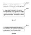
- Various embodiments disclosed hereinrelate to devices and methods that enable people to observe remote locations. Certain embodiments relate to using a computing device to see video taken by a remotely located camera.
- Video camerascan record images of various events that are viewable by remotely located people. Additionally, video cameras can be supported by objects such as tripods. Furthermore, video cameras often require electrical power. Some video cameras receive electrical power from batteries and/or power outlets.
- the disclosuredescribes methods for using a light socket camera to trigger an appliance.
- the methodscan include using a light socket camera to receive an audible instruction from a user, wherein the audible instruction is an instruction to trigger an appliance communicatively coupled to the light socket camera and electrically coupled to a building.
- the light socket cameracan be electrically coupled to the building.
- the light socket cameracan include an outer housing comprising a proximal end, a distal end that is opposite the proximal end, and a sidewall that extends between the proximal end and the distal end, a camera coupled to the outer housing, whereby the camera is configured to record a video, a speaker located within an internal portion of the outer housing, whereby the speaker is configured to transmit an audible message, a microphone located within an internal portion of the outer housing, whereby the microphone is configured to receive an audible instruction, a communication module located within an internal portion of the outer housing, whereby the communication module is configured to connect to a network, and a screw thread contact located adjacent the proximal end of the outer housing, whereby the screw thread contact is rotatably attached to a light socket of the building.
- methodscan also include using the light socket camera to transmit a trigger command to the appliance, wherein the trigger command triggers the appliance to perform an operation.
- methodscan also include performing the operation via the appliance.
- the audible instructioncan be a first audible instruction to activate the appliance.
- the methodcan further include using the light socket camera to receive a second audible instruction from the user, wherein the second audible instruction comprises an instruction to deactivate the appliance.
- methodscan include using the light socket camera to transmit a deactivation command to the appliance.
- methodscan also include deactivating the appliance.
- the buildingcan include an enclosed interior portion and an exterior portion opposite the interior portion.
- at least a portion of the applianceis located along the exterior portion of the building, and at least a portion of the light socket camera is located along the exterior portion of the building.
- the applianceis located entirely within the interior portion of the building, and the light socket camera is located entirely within the interior portion of the building.
- at least a portion of the applianceis located along the exterior portion of the building, and wherein the light socket camera is located entirely within the interior portion of the building.
- the buildingcan comprise a first room and a second room.
- the light socket cameracan be located in the first room and the appliance can be located in the second room.
- the appliancecan be selected from the group consisting of a light, television, garage door opener, and door lock.
- the appliancecan be a light
- the audible instructioncan be a first audible instruction comprising an instruction to illuminate the light.
- the methodcan further include using the light socket camera to receive a second audible instruction from the user, wherein the second audible instruction comprises an instruction to deactivate the light.
- methodscan include using the light socket camera to transmit a deactivation command to the light.
- methodscan include deactivating the light.
- the appliancecan be a television
- the audible instructioncan be a first audible instruction comprising an instruction to activate the television.
- Methodscan include using the light socket camera to receive a second audible instruction from the user, wherein the second audible instruction comprises an instruction to deactivate the television.
- methodscan include using the light socket camera to transmit a deactivation command to the television.
- methodscan include deactivating the television.
- Methodscan also include using the light socket camera to receive a third audible instruction from the user, wherein the third audible instruction comprises an instruction to change an input channel of the television.
- methodscan include using the light socket camera to transmit a change command to the television.
- methodscan include changing the input channel of the television.
- the appliancecan be a garage door opener
- the audible instructioncan be a first audible instruction comprising an instruction to open a garage door mechanically coupled to the garage door opener.
- Methodscan further include using the light socket camera to receive a second audible instruction from the user, wherein the second audible instruction comprises an instruction to close the garage door.
- methodscan include using the light socket camera to transmit a close command to the garage door opener.
- methodscan include closing the garage door.
- Methodscan also include using the light socket camera to receive a second audible instruction from the user, wherein the second audible instruction comprises an instruction to lock the door lock.
- methodscan include using the light socket camera to transmit a lock command to the door lock.
- methodscan include moving a lock of the door lock to a locked position.
- the light socket cameracan be a first light socket camera
- the appliancecan include a second light socket camera having a camera, a speaker, and a microphone, wherein the second light socket camera is communicatively coupled to the first light socket camera.
- the second light socket cameracan be electrically coupled to the building and mechanically coupled to an electrical outlet of the building.
- Methodscan include using the light socket camera to receive a second audible instruction to determine whether a visitor is located within a line of sight of the second light socket camera.
- methodscan include using the light socket camera to transmit a line of sight command to the second light socket camera.
- methodscan also include determining whether the visitor is located within the line of sight of the second light socket camera.
- the audible instructioncan further include an instruction to determine an identity of the visitor.
- methodscan include using the light socket camera to transmit an identity command to the second light socket camera.
- methodscan include determining the identity of the visitor.
- Using the light socket camera to determine the identity of the visitorcan comprise using the light socket to determine the identity of the visitor via one of facial recognition, iris recognition, and retina scanning.
- the appliancecan be a first appliance, and the audible instruction can be a first audible instruction comprising an instruction to activate the first appliance.
- Methodscan further include using the light socket camera to receive a second audible instruction from the user.
- the second audible instructioncan include an instruction to activate a second appliance.
- methodscan include using the light socket camera to transmit an activation command to the second appliance.
- methodscan include activating the second appliance.
- the first appliancecan be a light
- the second appliancecan be a television.
- Methodscan further include using the light socket camera to receive a third audible instruction from the user, wherein the third audible instruction comprises an instruction to unlock a door lock.
- methodscan include using the light socket camera to transmit an unlock command to the door lock.
- methodscan include moving a lock of the door lock to the unlocked position.
- Methodscan include using the communication module to wirelessly transmit the command to the appliance via one of Wi-Fi, Bluetooth, radio frequency, Near Field Communication, and infrared.
- methodscan include using the communication module to transmit the command to the appliance via a wire, wherein the wire is electrically and communicatively coupled to the light socket camera.
- the wirecan comprise a copper wire located within the building, wherein the copper wire is electrically coupled to a transformer such that the copper wire transmits electricity from the transformer to the light socket camera, and the copper wire transmits electricity from the transformer to the appliance, and wherein the copper wire communicatively transmits the command from the light socket camera to the appliance.
- the methodcan further include using the light socket camera to determine the identity of the user.
- methodscan include using the light socket camera to determine whether the user is an authorized user or an unauthorized user of the appliance.
- methodscan include using the light socket camera to transmit the trigger command to the appliance, wherein the trigger command triggers the appliance to perform an operation.
- methodscan include performing the operation via the appliance.
- Methodscan also include using the light socket camera to determine whether an Internet connection exists between the light socket camera and a remote server. In response to determining that the Internet connection does not exist between the light socket camera and the remote server, methods can include using the light socket camera to transmit the trigger command to the appliance via a WiFi router. In response to determining that the Internet connection does exist between the light socket camera and the remote server, methods can include using the light socket camera to transmit the trigger command to the appliance via the remote server.
- methodscan include using the light socket camera to determine whether the light socket camera is electrically coupled to the building. In response to determining the light socket camera is not electrically coupled to the building and in response to receiving the audible instruction from the user, methods can include using the light socket camera to activate a light on the light socket camera to thereby illuminate an area adjacent the light socket camera.
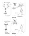
- FIG. 1 aillustrates a front view of a communication system, according to some embodiments.
- FIG. 1 billustrates a front view of a security system, according to some embodiments.
- FIG. 2illustrates a computing device running software, according to some embodiments.
- FIG. 3illustrates an embodiment in which a security system is connected to a building, according to some embodiments.
- FIG. 4illustrates a perspective view of a light socket, according to some embodiments.
- FIG. 5illustrates a perspective view of a light bulb mechanically and electrically coupled to a light socket, according to some embodiments.
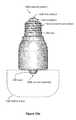
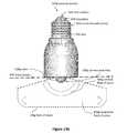
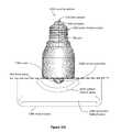
- FIG. 6illustrates a perspective view of a security system prior to the security system being mechanically and electrically coupled to the light socket, according to some embodiments.
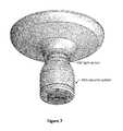
- FIG. 7illustrates the security system mechanically and electrically coupled to the light socket, according to some embodiments.
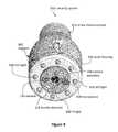
- FIGS. 8 and 9illustrate perspective views of security systems, according to some embodiments.
- FIG. 10illustrates a perspective view of electrical contacts, according to some embodiments.
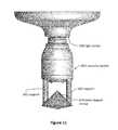
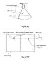
- FIG. 11illustrates a side view of a security system with a cone-shaped mirror, according to some embodiments.
- FIG. 12illustrates a perspective view of the security system with a cone-shaped mirror, according to some embodiments.
- FIGS. 13 a , 13 b , 13 c , and 13 dillustrate side views of security systems with respective dome camera assembly, according to various embodiments.
- FIG. 13 eillustrates a top-down view of a security system with a horizontal field of vision, according to some embodiments.
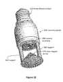
- FIG. 14illustrates a perspective view of a security system, according to some embodiments.
- FIGS. 15 and 16illustrate a user interface with an adjustable viewing orientation, according to some embodiments.
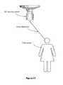
- FIG. 17illustrates a security system detecting a visitor, according to some embodiments.
- FIGS. 18-27illustrate flow-charts of various methods of using a security system, according to various embodiments.
- FIG. 28 aillustrates a security system detecting a sound, according to an embodiment.
- FIGS. 28 b - 28 fillustrate various responses to detecting the sound from FIG. 28 a , according to various embodiments.
- FIGS. 29 and 30illustrate flow-charts of various methods of using a security system, according to various embodiments.
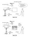
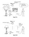
- FIG. 31 aillustrates a security system detecting an audible instruction, according to an embodiment.
- FIGS. 31 b - 31 fillustrate various responses to detecting the audible instruction from FIG. 31 a , according to various embodiments.
- FIGS. 32 a and 32 billustrate various embodiments of a security system, first appliance and second appliance being located inside or outside a building, according to various embodiments.
- FIGS. 33 a and 33 billustrate various embodiments of a security system being connected to an appliance via a wireless connection and a wired connection, according to various embodiments.
- FIG. 34illustrates a flow-chart of a method of using a security system, according to an embodiment.
- Communication systemscan provide a secure and convenient way for a remotely located individual to see and/or communicate with a person who is within the field of vision of a camera and/or within the range of a microphone.
- Communication systemscan include a camera that is attached to a light socket to couple the camera to a wall and to provide electricity to the camera.
- Some communication systemscan allow an individual to hear, see, and talk with visitors.
- communication systemscan use a computing device to enable a remotely located person to see, hear, and/or talk with visitors.
- Computing devicescan include computers, laptops, tablets, mobile devices, smartphones, cellular phones, and wireless devices (e.g., cars with wireless communication).
- example computing devicesinclude the iPhone, iPad, iMac, MacBook Air, and MacBook Pro made by Apple Inc. Communication between a remotely located person and a visitor can occur via the Internet, cellular networks, telecommunication networks, and wireless networks.
- communication systems 200can be a portion of a smart home hub. Communication systems 200 can facilitate home automation.
- cameras 208are electrically coupled to a light socket of a building 300 and are integrated into a holistic home automation system and/or home security system.
- Various systems described hereinenable home surveillance and/or complete home automation.
- Cameras 208 threadably screwed into an interior light socketcan enable a remote user to see events inside of a building 300 (shown in FIG. 3 ).
- cameras 208 threadably screwed into exterior light socketscan enable a remote user to see events outside of a building 300 .
- the security system 202 ccontrols various electrical items in a home (e.g., lights, air conditioners, heaters, motion sensors, garage door openers, locks, televisions, computers, entertainment systems, appliances, pool monitors, elderly monitors, and the like).
- the computing device 204controls the security system 202 c and other electrical items in a home (e.g., lights, air conditioners, heaters, motion sensors, garage door openers, locks, televisions, computers, entertainment systems, appliance, pool monitors, elderly monitors, and the like).
- FIG. 1illustrates a front view of a communication system embodiment.
- the communication system 200can include a security system 202 c (e.g., a camera assembly) and a computing device 204 .
- a security system 202 ce.g., a camera assembly
- the security system 202 ccan include a camera assembly 208 .
- the camera assembly 208can include a video camera, which in some embodiments is a webcam.
- the camera assembly 208can be configured to take videos of a surrounding area for viewing via the Internet.
- the camera assembly 208can be a still camera, any type of digital camera, virtual camera, and the like.
- the camera assembly 208can be any type of camera or optical instrument that records images that can be stored directly, transmitted to another location, or both.
- the security system 202 ccan include a proximal end 280 and a distal end 282 that is opposite the proximal end 280 .
- the camera assembly 208can be located at the distal end 282 of the security system 202 c .
- the camera assembly 208can be positioned at any location on the security system 202 c , such as the sidewall 680 .
- the security system 202 ccan also include a foot contact 618 located at the proximal end 280 of the security system 202 c.
- the security system 202 ccan include more than one camera assembly 208 .
- the security system 202 cmay include two cameras.
- the security system 202 cincludes a first camera disposed at the distal end 282 of the security system 202 c , and a second camera disposed along the sidewall 680 of the security system 202 c . In this manner the second camera may face perpendicular to the direction the first camera is facing. This may allow the security system 202 c to have a larger field of vision of the area to which the security system 202 c is monitoring.
- the security system 202 ccan also include a third camera, a fourth camera, and a fifth camera.
- the camerascan be mounted at any location along the security system 202 c to thereby expand the field of vision of the security system 202 c .
- the camera(s) 208may be configured to move away from the security system 202 c and pivot along at least two axes. The movement of the camera(s) 208 may be controlled via manual manipulation by a person, a command from a remote computing device 204 , automatically in response to the occurrence of an event, or the like.
- the security system 202 ccan include a diagnostic light 216 and a power indicator light 220 .
- the diagnostic light 216is a first color (e.g., blue) if the security system 202 c and/or the communication system 200 is connected to a wireless Internet network and is a second color (e.g., red) if the security system 202 c and/or the communication system 200 is not connected to a wireless Internet network.
- the power indicator 220is a first color if the security system 202 c is connected to a power source.
- the power sourcecan be power supplied by the building 300 to which the security system 202 c is attached.
- the security system 202 ccan receive electricity via the light socket to which the security system 202 c is attached.
- the power indicator 220is a second color or does not emit light if the security system 202 c is not connected to the power source.
- the security system 202 c(e.g., a camera assembly) can include an outer housing 634 , which can be water resistant and/or waterproof.
- the outer housing 634can be made from metal or plastic, such as molded plastic with a hardness of 60 Shore D. In some embodiments, the outer housing 634 is made from brushed nickel or aluminum.
- the outer housing 634can be rigid.
- the security system 202 ccan be electrically coupled to a power source, such as wires electrically connected to a building's electrical power system.
- the security system 202 cincludes a battery for backup and/or primary power.
- the security system 202 ccan include a screw thread contact 614 having a proximal end adjacent the foot contact 618 and a distal end that is opposite the proximal end.
- the distal end of the screw thread contact 614can be located adjacent the proximal end of the outer housing 634 .
- the screw thread contact 614can also include a threaded sidewall that extends between the proximal end and the distal end of the screw thread contact 614 . In this manner, the threaded sidewall of the screw thread contact 614 can be configured to rotatably attach to the light socket 650 .
- the security systemcan include lights 626 , which can be LED lights configured to illuminate a room and/or an outdoor area.
- the lights 626can provide at least 10 lumens, at least 1,000 lumens, at least 4,000 lumens, and/or less than 40,000 lumens.
- the lights 626can be aligned such that the lights 626 are parallel to a central axis 266 of a screw thread contact 614 .
- the lights 626can be oriented such that they face away from the foot contact 618 .
- the security system 202 ccan include lights 630 , which can be infrared lights.
- the lights 630can illuminate an area in front of the camera assembly's 208 field of vision to enable the camera assembly 208 to capture easily viewable and high-quality video.
- the lights 630can be located at the distal end 282 of the security system 202 c , adjacent to the camera assembly 208 .
- Infrared lightcan be suitable for nighttime video recording.
- the security system 202 cincludes a photosensor and/or a photodetector to determine whether the field of vision of the camera assembly 208 is illuminated.
- the security system 202 ccan illuminate the light and use the camera assembly 208 to record a video of the visitor. It should be appreciated that the security system 202 c can include any type of sensor configured to determine an amount of light, such as a reverse-biased light emitting diode (LED), photovoltaic cell, photodiode, ultraviolet light sensor, and the like.
- LEDreverse-biased light emitting diode
- photovoltaic cellphotovoltaic cell
- photodiodephotodiode
- ultraviolet light sensorand the like.
- the lights 626 and 630can be controlled by any number of means.
- the security system 202 ccan be configured to receive a first instruction from the remote computing device 204 .
- the first instructioncan include a command to illuminate either or both of the lights 626 and/or 630 .
- the security system 202 ccan illuminate the lights 626 and/or 630 .
- the security system 202 ccan receive a second instruction from the remote computing device 204 .
- the second instructioncan include a command to de-activate the lights 626 and/or 630 .
- the security system 202 ccan de-activate the lights 626 and/or 630 .
- the security system 202 ccan also be configured to illuminate and de-activate the lights 626 and/or 630 in a number of different manners.
- the security system 202 ccan be configured to receive an audible instruction via the microphone 234 of the security system 202 c .
- the audible instructioncan be a spoken command by the visitor to thereby illuminate and/or de-activate the lights 626 and/or 630 .
- the audible instructioncan be the visitor saying, “Turn lights on,” “Illuminate lights,” “Lights off,” “Dim lights,” and the like.
- the audible instructioncan be any spoken command or noise from the visitor, which is thereby received by the security system 202 c to illuminate the lights. Accordingly, in response to receiving the audible instruction from the visitor, the security system 202 c can illuminate or de-activate the lights 626 and/or 630 .
- the security system 202 ccan include a communication module 262 configured to enable wireless communication with the computing device 204 .
- the communication module 262can include a WiFi antenna and can be configured to enable the security system 202 c to connect to a wireless network 308 of a building 300 (shown in FIG. 3 ).
- Wireless communication 230can enable the security system 202 c (e.g., a camera assembly) to communicate with the computing device 204 .
- the security system 202 cmay include a communication module 262 located within an internal portion of the outer housing 634 .
- the communication module 262may be configured to connect to a wireless communication network. Some embodiments enable communication via cellular and/or WiFi networks. Some embodiments enable communication via the Internet. Several embodiments enable wired communication between the security system 202 c and the computing device 204 .
- the wireless communication 230can include the following communication means: radio, WiFi (e.g., wireless local area network), cellular, Internet, Bluetooth, telecommunication, electromagnetic, infrared, light, sonic, and microwave. Other communication means are used by some embodiments.
- the security system 202 ccan initiate voice calls or transmit text messages to a computing device 204 (e.g., a smartphone, a desktop computer, a tablet computer, a laptop computer).
- a computing device 204e.g., a smartphone, a desktop computer, a tablet computer, a laptop computer.
- NFCnear field communication
- the security system 202 c and/or the computing device 204can include a NFC tag.
- Some NFC technologiesinclude Bluetooth, radio-frequency identification, and QR codes.
- wireless charginge.g., near field charging, inductive charging
- inductive charginge.g., using an electromagnetic field to transfer energy between two objects.
- Some embodimentsinclude computer software (e.g., application software), which can be a mobile application designed to run on smartphones, tablet computers, and other mobile devices. Software of this nature is sometimes referred to as “app” software.
- the computer softwareincludes software designed to run on desktop computers and laptop computers.
- the computing device 204can run software with a graphical user interface.
- the user interfacecan include icons or buttons.
- the softwareis configured for use with a touch-screen computing device such as a smartphone or tablet.
- the security system 202 ccan include a motion detector 218 configured to detect the presence of people (e.g., in the outdoor area or room in which the security system 202 c is located) or objects.
- the security system 202 ccan also be placed outdoors to detect people or objects outside.
- the motion detector 218can be an infrared motion detector.
- the security system 202 ccan be attached to a light socket 650 to couple the security system 202 c to an electrical power source (e.g., of a building 300 shown in FIG. 3 ).
- the security system 202 ccan include a screw thread electrical contact 614 , which can comprise a conductive metal.
- the security system 202 ccan also include a foot electrical contact 618 , which can comprise a conductive metal.
- the screw thread contact 614can be electrically insulated from the foot electrical contact 618 by insulation 638 .
- the security system 202 ccan be coupled to the light socket 650 via any number of connection methods.
- the screw thread contact 614 of the security system 202 ccan be rotatably attached to the light socket 650 to thereby couple the security system 202 c to the light socket 650 .
- the foot contact 618 of the security system 202 ccan be electrically coupled to the foot contact 654 of the light socket 650 , to thereby couple the security system 202 c to the electrical power source (i.e. to energize the security system 202 c ).
- a power converter 610can be electrically coupled to the screw thread contact 614 and the foot contact 618 .
- the power converter 610can be configured to convert electricity from the building 300 (shown in FIG. 3 ) to a type of power that is more suitable for the security system 202 c .
- the power converter 610converts an input voltage to a lower voltage and/or converts AC to DC power.
- the power converter 610can be configured to adapt to the input voltages of any country, and thereby convert the input voltage to a voltage suited for the security system 202 c.
- FIG. 2illustrates a computing device 204 running software.
- the softwareincludes a user interface 240 displayed on a display screen 242 .
- the user interface 240can include a security system indicator 244 , which can indicate the location of the security system that the user interface is displaying. For example, a person can use one computing device 204 to control and/or interact with multiple security systems, such as one security system located at a front door and another security system located at a back door. Selecting the security system indicator 244 can allow the user to choose another security system (e.g., the back door security system rather than the front door security system).
- another security systeme.g., the back door security system rather than the front door security system.
- the user interface 240can include a connectivity indicator 248 .
- the connectivity indicatorcan indicate whether the computing device is in communication with a security system, the Internet, and/or a cellular network.
- the connectivity indicator 248can alert the user if the computing device 204 has lost its connection with the security system 202 c ; the security system 202 c has been damaged; the security system 202 c has been stolen; the security system 202 c has been removed from its mounting location; the security system 202 c has lost electrical power; and/or if the computing device 204 cannot communicate with the security system 202 c .
- the connectivity indicator 248alerts the user of the computing device 204 by flashing, emitting a sound, displaying a message, and/or displaying a symbol.
- a remote server 206transmits an alert (e.g., phone call, text message, image on the user interface 240 ) regarding the power and/or connectivity issue.
- the remote server 206can manage communication between the security system 202 c and the computing device 204 .
- information from the security system 202 cis stored by the remote server 206 .
- information from the security system 202 cis stored by the remote server 206 until the information can be sent to the computing device 204 , uploaded to the computing device 204 , and/or displayed to the remotely located person via the computing device 204 .
- the remote server 206can be a computing device that stores information from the security system 202 c and/or from the computing device 204 .
- the remote server 206is located in a data center.
- the computing device 204 and/or the remote server 206attempts to communicate with the security system 202 c . If the computing device 204 and/or the remote server 206 is unable to communicate with the security system 202 c , the computing device 204 and/or the remote server 206 alerts the remotely located person via the software, phone, text, a displayed message, and/or a website.
- the computing device 204 and/or the remote server 206attempts to communicate with the security system 202 c periodically; at least every five hours and/or less frequently than every 10 minutes; at least every 24 hours and/or less frequently than every 60 minutes; or at least every hour and/or less frequently than every second.
- the server 206can initiate communication to the computer device 204 and/or to the security system 202 c . In several embodiments, the server 206 can initiate, control, and/or block communication between the computing device 204 and the security system 202 c.
- a usercan log in to an “app,” website, and/or software on a computing device (e.g., mobile computing device, smartphone, tablet, desktop computer) to adjust the security system settings discussed herein.
- a computing devicee.g., mobile computing device, smartphone, tablet, desktop computer
- a computing devicecan enable a user to watch live video and/or hear live audio from a security system due to the user's request rather than due to actions of a visitor.
- Some embodimentsinclude a computing device initiating a live video feed (or a video feed that is less than five minutes old).
- the user interface 240displays an image 252 such as a still image or a video of an area near and/or in front of the security system 202 c .
- the image 252can be taken by the camera assembly 208 and stored by the security system 202 c , server 206 , and/or computing device 204 .
- the user interface 240can include a recording button 256 to enable a user to record images, videos, and/or sound from the camera assembly 208 , microphone of the security system 202 c , and/or microphone of the computing device 204 .
- the user interface 240includes a picture button 260 to allow the user to take still pictures and/or videos of the area near and/or in front of the security system 202 c .
- the user interface 240can also include a sound adjustment button 264 and a mute button 268 .
- the user interface 240can include camera manipulation buttons such as zoom, pan, and light adjustment buttons.
- the camera assembly 208automatically adjusts between Day Mode and Night Mode.
- Some embodimentsinclude an infrared camera and/or infrared lights to illuminate an area near the security system 202 c to enable the camera assembly 208 to provide sufficient visibility (even at night).
- buttonsinclude diverse means of selecting various options, features, and functions. Buttons can be selected by mouse clicks, keyboard commands, or touching a touch screen. Many embodiments include buttons that can be selected without touch screens.
- the user interface 240includes a quality selection button, which can allow a user to select the quality and/or amount of data transmitted from the security system 202 c to the computing device 204 and/or from the computing device 204 to the security system 202 c.
- videocan be sent to and/or received from the computing device 204 using video chat protocols such as FaceTime (by Apple Inc.) or Skype (by Microsoft Corporation).
- videochat protocolssuch as FaceTime (by Apple Inc.) or Skype (by Microsoft Corporation).
- these videosare played by videoconferencing apps on the computing device 204 instead of being played by the user interface 240 .
- the user interface 240can include a termination button 276 to end communication between the security system 202 c and the computing device 204 .
- the termination button 276ends the ability of the person located near the security system 202 c (i.e., the visitor) to hear and/or see the user of the computing device 204 , but does not end the ability of the user of the computing device 204 to hear and/or see the person located near the security system 202 c.
- a button 276is both an answer button (to accept a communication request from a visitor) and a termination button (to end communication between the security system 202 c and the computing device 204 ).
- the button 276can include the word “Answer” when the system is attempting to establish two-way communication between the visitor and the user. Selecting the button 276 when the system is attempting to establish two-way communication between the visitor and the user can start two-way communication.
- the button 276can include the words “End Call” during two-way communication between the visitor and the user. Selecting the button 276 during two-way communication between the visitor and the user can terminate two-way communication. In some embodiments, terminating two-way communication still enables the user to see and hear the visitor. In some embodiments, terminating two-way communication causes the computing device 204 to stop showing video from the security system and to stop emitting sounds recorded by the security system.
- the user interface 240opens as soon as the security system 202 c detects a visitor (e.g., senses indications of a visitor). Once the user interface 240 opens, the user can see and/or hear the visitor.
- the security system 202 ccan include a microphone 234 and a speaker 236 to enable the user to hear the visitor and to enable the visitor to hear the user.
- the speaker 236may be configured to transmit an audible message to the visitor and the microphone 234 may be configured to receive an audible message from the visitor.
- the speaker 236 and microphone 234are located within an internal portion of the outer housing 634 . However, in other embodiments, the speaker 236 and microphone 234 are located along an external surface of the outer housing 634 .
- the security system 202 ccan enable the user to communicate with the visitor.
- Some method embodimentsinclude detecting a visitor with a security system.
- the methodscan include causing the user interface 240 (shown in FIG. 2 ) to display on a remote computing device 204 due to the detection of the visitor (e.g., with or without user interaction).
- the methodscan include displaying video from the security system and/or audio from the security system.
- the softwareincludes means to start the video feed on demand.
- a user of the computing devicemight wonder what is happening near the security system 202 c .
- the usercan open the software application on the computing device 204 and instruct the application to show live video and/or audio from the security device 202 c even if no event near the security system 202 c has triggered the communication.
- the security device 202 ccan be configured to record video, images, and/or audio when the security device 202 c detects movement and/or the presence of a person.
- the user of the computing device 204can later review all video, image, and/or audio records when the security device 202 c detected movement and/or the presence of a person.
- the server 206controls communication between the computing device 204 and the security system 202 c , which can include a camera, a microphone, and a speaker. In several embodiments, the server 206 does not control communication between the computing device 204 and the security system 202 c.
- data captured by the security system and/or the computing device 204is stored by another remote device such as the server 206 .
- Cloud storage, enterprise storage, and/or networked enterprise storagecan be used to store video, pictures, and/or audio from the communication system 200 or from any part of the communication system 200 .
- the usercan download and/or stream stored data and/or storage video, pictures, and/or audio. For example, a user can record visitors for a year and then later can review the visits from the last year.
- remote storage, the server 206 , the computing device 204 , and/or the security system 202 ccan store information and statistics regarding visitors and usage.
- the communication system 200can include the security system 202 c , the computing device 204 , and/or the server 206 . Some communication systems use many systems to enable communication between the security system 202 c and the computing device 204 .
- FIG. 3illustrates an embodiment in which a security system 202 c is connected to a building 300 , which can include an entryway 310 that has a door 254 .
- Electrical wires 304can electrically couple the security system 202 c to the electrical system of the building 300 such that the security system 202 c can receive electrical power from the building 300 (e.g., via a light socket that is attached to the building 300 ).
- a wireless network 308can allow devices to wirelessly access the Internet.
- the security system 202 ccan access the Internet via the wireless network 308 .
- the wireless network 308can transmit data from the security system 202 c to the Internet, which can transmit the data to remotely located computing devices 204 .
- the Internet and wireless networkscan transmit data from remotely located computing devices 204 to the security system 202 c .
- a security system 202 cconnects to a home's WiFi.
- one computing device 204can communicate with multiple security systems 202 c .
- multiple computing devices 204can communicate with one security system 202 c.
- the security system 202 ccan communicate (e.g., wirelessly 230 ) with a television 306 , which can be a smart television. Users can view the television 306 to see a visitor and/or talk with the visitor.
- the visitor and user of the remote computing device 204are able to talk with each other, via the security system 202 c and the remote computing device 204 .
- the security system 202 cmay be configured to transmit a first audible message to the visitor.
- the first audible messagemay be received by a microphone in the remote computing device 204 and transmitted to the security system 202 c .
- the first audible messagemay be audibly transmitted to the visitor via the speaker 236 in the security system 202 c .
- the security systemmay be configured to transmit a second audible message to a user of the remote computing device 202 c .
- the second audible messagemay be received by the microphone 234 in the security system 202 c and transmitted to the remote computing device.
- the second audible messagemay audibly transmitted to the user via a speaker in the remote computing device 204 .
- FIG. 4illustrates a perspective view of a light socket 650 .
- the light socket 650can include a screw thread contact 652 configured to mechanically and electrically couple with the screw thread contact 614 of the security system 202 c (shown in FIG. 1 a ).
- the light socket 650can also include a foot contact 654 configured to electrically couple with the foot contact 618 of the security system 202 c (shown in FIG. 1 a ).
- the foot contact 654 of the light socket 650can be located at the distal end of the light socket 650 .
- the security system 202 ccan be described as having a proximal end and a distal end that is opposite the proximal end.
- the camera assembly 208can be located at the distal end of the security system 202 c .
- the security system 202 ccan include the foot electrical contact 618 located at the proximal end of the security system 202 c .
- the security system 202 ccan be oriented such that the foot electrical contact 618 faces the foot contact 654 of the light socket 650 . In this manner the distal end of the security system 202 c faces away from the foot contact 654 of the light socket 650 .
- the camera assembly 608can face away from the foot contact 654 of the light socket 650 .
- the security system 202 cis rotated as it is attached to the light socket 650 .
- the security system 202 ccan be rotated in a direction of rotation 690 about a first axis 266 to thereby attach the security system 202 c to the light socket 650 .
- the foot contact 654 of the light socket 650can be electrically coupled to the security system 202 c .
- the foot contact 654 of the light socket 650is electrically coupled to a light switch (not shown). In this manner, the foot contact 654 of the light socket 650 , and the foot contact 618 of the security system 202 c can be energized, when the light switch is activated (i.e. turned on).
- FIG. 5illustrates a perspective view of a light bulb 656 mechanically and electrically coupled to the light socket 650 .
- the light bulb 656can be removed and replaced by a security system that comprises lights and a camera.
- FIG. 6illustrates a perspective view of the security system 202 c just before the security system 202 c is screwed into the light socket 650 to mechanically couple the security system 202 c to a wall and/or to a building 300 . Screwing the security system 202 c into the light socket 650 also enables the security system 202 c to receive electricity from the building 300 (shown in FIG. 3 ).
- FIG. 7 aillustrates the security system 202 c screwed into the light socket 650 .
- the security system 202 cis electrically coupled to a power supply of the building 300 .
- the light socket 650can be located indoors or outdoors.
- FIG. 8illustrates a perspective view of the security system 202 c . Not all of the lights 626 , 630 are labeled to clarify other features.
- the camera assembly 208can be aligned with a central axis 266 of the screw thread contact 614 .
- the camera assembly 208can include a fisheye lens.
- the camera assembly 208can also include a cone-shaped mirror to enable viewing 360 degrees around the camera and/or around the outer housing 634 .
- Softwarecan be used to convert videos and/or pictures taken using the cone-shaped mirror into different formats (e.g., that are easier for users to interpret and/or include less distortion).
- FIGS. 9 and 10illustrate a security system 202 d that can include any of the features described in the context of the security system 202 c shown in FIGS. 1 a , 1 b and 3 - 8 .
- the security system 202 dcan also be configured to screw into the light socket 650 . In this manner, the security system 202 d can be rotated in a direction of rotation 690 about a first axis 266 to thereby attach the security system 202 d to the light socket 650 .
- the security system 202 dcan include a camera assembly 208 d that faces a radial direction that is perpendicular to the first axis 266 .
- the security system 202 dcan include a motion detector 218 d configured to detect visitors (e.g., people moving outside of a building 300 , people moving inside of a room).
- the motion detector 218 dcan be located at the distal end of the security system 202 c such that the motion detector 218 d faces away from the foot contact 618 of the security system 202 c.
- the security system 202 dcan include a rotatable camera housing 658 .
- a camera assembly 208 dcan be coupled to the rotatable camera housing 658 such that the camera assembly 208 d rotates around the perimeter of the outer housing 634 of the security system 202 d as the camera housing 658 rotates around the perimeter of the outer housing 634 .
- the camera housing 658can rotate around a central axis 266 of the screw thread contact 614 .
- the camera housing 658can rotate in response to an event, such as a person entering a room, outdoor area, or space adjacent to the security system 202 c .
- the motion detector 218 dcan detect the person(s), such as the visitor(s), and in response to the motion detector 218 d detecting the person(s), the security system 202 c can cause the camera housing 658 to rotate to a position whereby the camera assembly 208 can record an image and/or video of the person(s).
- the camera housing 658can be rotated via any number of rotation methods.
- the rotation of the camera housing 658is caused by a command from a remote computing device, such as a smart phone, tablet, or other cellular device.
- a remote computing devicesuch as a smart phone, tablet, or other cellular device.
- a user of the remote computing devicecan input a command into an app that is run on the remote computing device.
- the commandcan then be transmitted from the remote computing device to the security system 202 c , to thereby rotate the camera housing 658 .
- the sidewall 680 of the security system 202 ccan comprise a first portion, such as an outer housing 634 , and a second portion, such as a rotatable camera housing 658 , which is distal to the first portion.
- the second portion, or rotatable camera housing 658can be rotatable about the first axis 266 .
- the camera housing 658can be manually rotated by the user. For example, the user can grip the camera housing 658 with his or her hand and rotate the camera housing 658 to a desired position. As well, the camera housing 658 can be rotated by the security system 202 c , such as, in response to an event.
- the security system 202 cwhen the security system 202 c detects the visitor, via the motion detector 218 d , the security system 202 c can then determine whether the visitor is located within a field of vision of the camera 208 . Accordingly, in response to determining that the visitor is not located within the field of vision of the camera 208 , the security system 202 c can rotate the second portion, or camera housing 658 . Furthermore, the security system 202 c can rotate the camera 208 about the first axis until 266 the visitor is within a field of vision of the camera 208 .
- the security system 202 cmay be configured to receive an instruction from a remote computing device 204 .
- the instructionmay include a command to rotate the second portion, or camera housing 658 , to any location as determined by the user of the remote computing device 204 .
- the security system 202 cmay be configured to rotate the second portion such that the camera 208 rotates about the first axis 266 .
- the user of the remote computing device 204may be able to remotely rotate the camera housing 658 to thereby change the field of vision of the camera 208 .
- the security system 202 dcan use a microphone 234 to listen for visitors. When the security system 202 d detects visitors (e.g., via motion or sound), the security system 202 d can turn on LED lights 626 , record sounds from the visitors, and/or take videos of the visitors. In some embodiments, the security system 202 d records when visitors move by the security system 202 d.
- FIG. 10illustrates a perspective view of electrical contacts. Connecting the security system 202 d to the light socket 650 can enable the security system 202 d to be electrically connected to a power supply.
- FIG. 11illustrates a side view of a security system 202 c with a cone-shaped mirror 670 .
- Supports 662can extend from an end of the security system 202 c that is opposite an end that includes the screw thread contacts 614 (labeled in FIG. 12 ).
- FIG. 12illustrates a perspective view of the security system with a cone-shaped mirror 670 .
- the camera assembly 208can include a camera that is oriented towards the cone-shaped mirror to enable the security system 202 c to record visitors in many directions around the security system 202 c .
- Softwarecan be used by the security system 202 c , the remote computing device 204 , and/or the server 206 to reduce and/or eliminate distortion in pictures taken using the security system 202 c.
- FIG. 13 aillustrates a side view of a security system 202 e with a dome camera assembly 208 e .
- the dome camera assembly 208 ecan have a shape that is half of a sphere.
- the dome camera assembly 208 eincludes an outer cover 228 that has a curved and/or spherical shape (e.g., half of a sphere).
- the cover 228can be a translucent material such as plastic and/or polycarbonate.
- the field of vision 238 of the dome camera assembly 208 ecan include half of a sphere.
- the field of vision 238includes approximately 360 degrees around the base of the cover 228 and/or around a central axis 266 of the screw thread contacts 614 .
- the field of vision 238includes at least 330 degrees around the base of the cover 228 .
- the field of vision 238is approximately 180 degrees in a plane that includes the central axis 266 of the screw thread contacts 614 (e.g., in the plane represented by the page on which FIG. 13 a appears).
- the field of vision 238is at least 140 degrees and/or less than 260 degrees in a plane that includes the central axis 266 .
- FIGS. 13 b - 13 efurther illustrate the field of vision in various embodiments.
- the field of vision 238 gcan be defined by a vertical field of vision 692 g and a horizontal field of vision 694 g .
- the vertical field of vision 692 gcan be any angle less than 180 degrees (as shown by the distal plane 693 ), such as 140 degrees.
- FIGS. 13 b - 13 eare side views, the horizontal field of vision 692 g and the vertical field of vision 694 g are actually radial, meaning that they extend 360 degrees around the perimeter of the camera assembly 208 g . This 360 degree periphery is further illustrated in FIG. 13 e .
- FIG. 13 eThis 360 degree periphery is further illustrated in FIG. 13 e .
- FIG. 13 eis a top down view, looking from above the security system (when it is mounted to the light socket 650 ) to the ground below the security system.
- FIG. 13 eshows that the horizontal field of vision 694 , 694 g actually covers 360 degrees around the perimeter of the security system and the axis 266 . While the vertical field of vision is not illustrated in FIG. 13 e , the vertical field of vision is also radial, in that it covers the 360 degree area around the security system.
- the security system 202 h illustrated in FIG. 13 cmay define a 180 degree vertical field of vision, which means that the camera assembly 208 h is able to see anything that is level with or below the distal plane 693 .
- the security system 202 jmay be configured to achieve a vertical field of vision 692 j that is greater than 180 degrees.
- some embodimentsmay have a vertical field of vision equal to at least 250 degrees, up to 250 degrees, up to 280 degrees, and in some embodiments, up to 300 degrees. (It should be appreciated that in some embodiments that utilize multiple cameras, a vertical field of vision of up to 360 degrees may be achieved.)
- the camera assembly 208 jmay be configured to move vertically downward.
- the camera assembly 208 jmay be configured to move along a camera assembly direction of movement 209 j , as shown in FIG.
- the camera assembly 208 jmay thereby gain separation from the distal end of the security system 202 j . This may allow the camera assembly 208 j to achieve a greater line of sight past the sidewalls in the upward, or proximal, direction.
- the camera assembly 208 hmay be configured to engage mechanical latches to secure the camera assembly 208 h at discrete locations along the direction of movement 209 h .
- the camera assembly 208 hmay be configured to be retained at any location along the direction of movement 209 h via friction.
- the camera assembly 208 hmay be threadably engaged and disengaged at various locations along the direction of movement 209 h . As well, once the camera assembly 208 h has been moved to its desired vertical position, the camera assembly 208 h is still thereby mechanically and electrically coupled to the security system.
- the camera assembly 208 hmay be vertically moved along the direction of movement 209 h in response to any command or manual movement.
- the camera assembly 208 hmay be moved in response to a command from a remote computing device 204 .
- the camera assembly 208 hmay be moved along the direction of movement 209 h in response to detecting a visitor.
- the camera assembly 208 hmay be positioned in a retracted position, whereby the camera assembly 208 h is located substantially within the security system as shown in FIGS. 13 c and 13 d . Accordingly, in response to the motion detector 218 detecting a visitor, the camera assembly 208 h may then move to an extended position (as shown in FIG. 13 d ) to capture a greater vertical field of vision than in the retracted position.
- the camera assembly 208 hmay be manually moved by a user.
- FIG. 14illustrates a perspective view of the security system 202 e from FIG. 13 a .
- the dome camera assembly 208 ecan be used with any of the security systems described herein.
- the security system 202 ecan include lights (e.g., LEDs) on an end that is opposite the end that includes the screw thread contacts 614 .
- any of the security systems described hereincan use the methods and systems described in U.S. Nonprovisional patent application Ser. No. 14/463,548; filed Aug. 19, 2014; and entitled DOORBELL COMMUNICATION SYSTEMS AND METHODS; the entire contents of which are incorporated herein by reference.
- the grid sensor methodscan be used with security systems 202 c , 202 d , and 202 e .
- the security system embodiments described in U.S. Nonprovisional patent application Ser. No. 14/463,548can be replaced with security systems 202 c , 202 d , and 202 e .
- Security systems 202 c , 202 d , and 202 ecan be used in the context of the security systems described in any of the patent applications incorporated by reference.
- Embodimentscan include changing the viewing orientations (e.g., viewing angles) via software (e.g., an “app”) and/or via a user interface 240 on a display screen 242 of a computing device 204 (see FIG. 2 ).
- softwaree.g., an “app”
- a user interface 240on a display screen 242 of a computing device 204 (see FIG. 2 ).
- Camerascan be mounted in a lamp, jutting out of a wall (e.g., horizontally), and upside down (e.g., hanging down from a ceiling).
- the software and/or user interface 240can enable users to select a button to adjust the viewing orientation a certain amount (e.g., 90 degrees).
- FIG. 15illustrates a user interface 240 .
- the image 252 in FIG. 15is oriented as a landscape, which can span entire viewing portion of the display screen 242 of the remote computing device 204 .
- the usercan adjust the viewing orientation by selecting an orientation button (not shown), or simply by rotating the remote computing device 204 to the position of the desired orientation (e.g. if you want to view portrait, just the remote computing device rotate by ninety degrees as shown in FIG. 16 ). Accordingly, in some embodiments, selecting the orientation button shifts the image 252 ninety degrees.
- FIG. 16illustrates the new orientation of the image 252 after selecting the orientation button, or rotating the remote computing device 204 to the desired orientation.
- the security systemautomatically detects the orientation in which the camera is inserted into a light socket.
- the security systemcan then automatically adjust the viewing orientation in response to the detected orientation (e.g., so the image 252 appears right-side up).
- the security systemcan detect the inserted orientation via an accelerometer 274 .
- Many embodimentsmay utilize the visitor identification abilities of the person using the remote computing device 204 (shown in FIG. 1 a ).
- Various technologiescan be used to help the user of the remote computing device 204 to identify the visitor.
- Some embodimentsuse automated visitor identification that does not rely on the user, some embodiments use various technologies to help the user identify the visitor, and some embodiments display images and information (e.g., a guest name) to the user, but otherwise do not help the user identify the visitor.
- the camera assembly 208can be configured to visually identify visitors through machine vision and/or image recognition.
- the camera assembly 208can take an image of the visitor.
- Software run by any portion of the systemcan then compare select facial features from the image to a facial database.
- the select facial featuresinclude dimensions based on facial landmarks. For example, the distance between a visitor's eyes; the triangular shape between the eyes and nose; and the width of the mouth can be used to characterize a visitor and then to compare the visitor's characterization to a database of characterization information to match the visitor's characterization to an identity (e.g., an individual's name, authorization status, and classification).
- Some embodimentsuse three-dimensional visitor identification methods.
- Some embodimentsinclude facial recognition such that the camera assembly 208 waits until the camera assembly 208 has a good view of the person located near the security system 202 c and then captures an image of the person's face.
- a visitor's identitycan establish a visitor's identity by detecting a signal from a device associated with the visitor (e.g., detecting the visitor's smartphone). Examples of such a signal include Bluetooth, WiFi, RFID, NFC, and/or cellular telephone transmissions.
- many embodimentscan identify an identity of a visitor and determine whether the visitor is authorized to be located in a predetermined location.
- the light socket 650may be located in a room inside a building 300 .
- the security system 202 ccan determine whether the visitor is authorized to be located in the room. In response to determining that the visitor is not authorized to be located in the room, the security system 202 c can transmit an alert to the remote computing device 204 to notify a user of the remote computing device 204 that the visitor is not authorized to be located in the room.
- the security system 202 cmay be located outside of a building 300 , for example, near a swimming pool. Accordingly, the security system 202 c may be used to determine the identity of the visitor and thereby determine whether the visitor is authorized to be located near the swimming pool. This may allow the user to monitor the swimming pool to determine if small children and/or any other unauthorized people approach the swimming pool. In effect, the security system 202 c can be used as a safety monitor.
- the security system 202 ccan also sound an audible message to warn the visitor that he or she is not authorized to be located in the room or outdoor area (e.g. swimming pool). For example, in response to determining that the visitor is not authorized to be located in the room or outdoor area, the security system 202 c may broadcast a predetermined audible message, via the speaker 236 in the security system 202 c , to notify the visitor that the visitor is not authorized to be located in the room or outdoor area.
- the security system 202 cmay also be configured to allow the user of the remote computing device 204 to speak to the visitor that is not authorized to be located in the room or outdoor area.
- the usermay speak a message into the remote computing device 204 , which may then be transmitted to the security system 202 c and sounded via the speaker in the security system 202 c (e.g. “Mitch, you are not allowed to be in the swimming pool after dark.”).
- Embodiments of the security system 202 cmay also save a history of times when the visitor was detected in the room or outdoor area by the security system 202 c . It should be appreciated that this may also be used for a variety of purposes.
- the usermay have a dog walker walk the user's dog when the user is gone at work.
- the security system 202 cmay be configured to save a history of times when the dog walker arrives at the building 300 , which may allow the user may be able to oversee and determine if the dog walker is walking the user's dog as promised. This may be helpful when the user pays the dog walker's invoice.
- the usercan review the history to determine whether the dog walker's visits to the buildings match the invoiced dates.
- the person of ordinary skill in the artwill recognize a variety of situations to utilize this technology.
- the security system 202 cmay take action in response to determining that the visitor is authorized to be located in the room. For example, the security system 202 c may transmit a second alert to the remote computing device 204 , wherein the second alert notifies the user of the remote computing device 204 that the visitor is located in the room. In some embodiments, the second alert may also notify the user of the remote computing device 204 that the visitor is authorized to be located in the room.
- the security systemmay utilize any technology capable of identifying a person or a remote computing device, such as facial recognition of a visitor, near field communication of a remote computing device 204 (e.g. identifying a remote computing device 204 associated with the visitor via Bluetooth), and the like.
- this disclosureincludes a variety of methods of using the security system to detect visitors, like the visitor 1700 shown in FIG. 17 .
- some methodsinclude using the security system 202 to detect a visitor (at step 1800 ), and using the camera to take video of the visitor (at step 1802 ).
- some embodimentsinclude transmitting the video to a remote computing device 204 (at step 1804 ) and displaying the video on the remote computing device 204 (at step 1806 ). This may effectively allow a remote user to monitor the activity around the security system 202 .
- some methodsmay include orienting the security system 202 such that the foot contact 618 of the security system 202 faces a foot contact 654 of the light socket 650 (at step 1900 ).
- FIG. 19further illustrates a method that may include attaching the security system 202 to the light socket 650 (at step 1902 ) and electrically coupling foot contact 618 of the security system 202 to the foot contact 654 of the light socket 650 . This electrical coupling may thereby energize the security system 202 to power all of the onboard components.
- FIG. 20shows a method that includes using the security system 202 to determine whether the visitor is authorized to be located in a room or in a space that the security system 202 is monitoring (at step 2000 ).
- the methodmay further include using the security system 202 to transmit an alert to a remote computing device 204 (at step 2002 ).
- the alertmay be a warning message, such as a text message or email, which warns the user that the unauthorized visitor is located in the room or space.
- some methodsmay further include using the security system 202 to determine the identity of the visitor, for example, via facial recognition or detecting a smart phone through NFC (at step 2004 ).
- the identity of the visitormay be included in the alert that is sent to the remote user. For example, if the security system detects an unauthorized user, such as a toddler, near a swimming pool, the alert might say, “Timmy is located near the pool.”
- some methodsmay further include using the security system to broadcast a predetermined audible message (at step 2100 ).
- a predetermined audible messagesuch as, “PLEASE MOVE AWAY FROM THE POOL!”
- Various methodsmay enable the visitor and remote user to communicate to each other through the security system 202 .
- some methodsmay include transmitting a first audible message to a visitor (at step 2200 ).
- the first audible messagemay be received by a microphone 234 in the remote computing device 204 and transmitted to the security system 202 .
- the first audible messagemay be audibly transmitted to the visitor via the speaker 236 in the security system 202 .
- methodsmay include transmitting a second audible message to a user of the remote computing device 204 (at step 2202 ).
- the second audible messagemay be received by the microphone 234 in the security system 202 and transmitted to the remote computing device 204 .
- the second audible messagemay be audibly transmitted to the user via a speaker 236 in the remote computing device 204 .
- methodsmay include using the motion detector 218 to detect the visitor (at step 2300 ) and using the security system 202 to determine whether the field of vision of the camera is illuminated (at step 2302 ). In response to detecting the visitor and in response to determining that the field of vision is not illuminated, the method may further include illuminating the light 626 and/or 630 and using the camera 208 to record a video of the visitor (at step 2304 ).
- methodsmay include receiving a first instruction from the remote computing device (at step 2400 ). In response to receiving the first instruction from the remote computing device 204 , methods may include using the security system 202 to illuminate the light (at step 2402 ). As well, some methods may include receiving a second instruction from the remote computing device 204 (at step 2404 ). In response to receiving the second instruction from the remote computing device 204 , methods may include using the security system 202 to de-activate the light 626 and/or 630 (at step 2406 ).
- Methodsmay also include receiving a first audible instruction via the microphone 234 of the security system 202 (at step 2408 ), and in response to receiving the first audible instruction from the visitor, the method may include using the security system 202 to illuminate the light 626 and/or 630 (at step 2410 ).
- some methodsmay include receiving a second audible instruction via the microphone 234 of the security system 202 (at step 2412 ) and in response to receiving the second audible instruction from the visitor, the method may include using the security system 202 to de-activate the light 626 and/or 630 (at step 2414 ).
- FIG. 25illustrates a method that includes orienting the security system 202 such that the proximal end 280 of the security system 202 faces a foot contact 654 of a light socket 650 (at step 2500 ) and thereby rotating the security system 202 about a first axis 266 to thereby attach the security system 202 to the light socket 650 (at step 2502 ).
- the methodmay also include electrically coupling the foot contact 618 of the security system 202 to the foot contact 654 of the light socket 650 (at step 2504 ).
- Methodsmay include using the motion detector 218 to detect the visitor (at step 2506 ) and in response to detecting the visitor, the methods may include using the security system 202 to determine whether the visitor is located within a field of vision 238 of the camera 208 (at step 2508 ). In response to determining that the visitor is not within the field of vision 238 of the camera 208 , methods may include using the security system 202 to rotate the second portion such that the camera 208 rotates about the first axis 266 until the visitor is within a field of vision 238 of the camera 208 (at step 2510 ).
- methodsmay include using the security system 202 to receive an instruction from a remote computing device 204 (at step 2600 ).
- the instructionmay comprise a command to rotate the second portion, or camera rotatable housing 658 .
- the methodmay include using the security system 204 to rotate the second portion such that the camera 208 rotates about the first axis 266 (at step 2602 ).
- some methodsmay include a first and second camera, and the methods associated may thereby include pivoting the second camera along at least a first direction and a second direction that is perpendicular to the first direction (at step 2700 ).
- the security system 202may also be configured to monitor a space by audibly detecting various sounds within the space.
- the soundsmay be adverse sounds, which may include breaking glass, gunshots, shouting, screaming, and the like.
- the security system 202may be configured to notify a party of the adverse sound(s).
- the adverse soundmay comprise any type of sound to indicate that someone or something is in need of help, that a problem has occurred, a crime is being committed, and the like.
- the disclosureincludes a method for detecting an adverse sound 2800 (at step 2900 ).
- the methodmay include using the security system 202 to notify a party 2804 (at step 2902 ).
- the party 2804 to be notifiedmay be any party that a user of the security system 202 may wish to contact, such as the user herself, or any contact listed on the user's contact list, such as a contact list stored within the user's remote computing device 204 .
- the party 2804may be an emergency dispatcher, such as a 9-1-1 dispatcher (in the U.S.) or a dispatcher who responds to any emergency (in the U.S. or any other country).
- the party 2804may be any party who may be interested in the occurrence of the adverse sound 2800 .
- the security system 202may notify the party 2804 by sending a notification from the security system 202 to a computing device 204 associated with the party 2804 .
- the security system 202may transmit the notification through any wireless or wired technology.
- the computing device 204may receive the notification via a wireless technology such as radio frequency, WiFi (e.g., wireless local area network), cellular, Internet, Bluetooth, telecommunication, electromagnetic, infrared, light, sonic, and microwave.
- WiFie.g., wireless local area network
- cellulare.g., Internet
- Bluetoothtelecommunication
- electromagnetic, infrared, light, sonic, and microwavee.g., electromagnetic, infrared, light, sonic, and microwave.
- the security system 202may wirelessly communicate with the computing device 204 via the communication module 262 of the security system 202 , which may be configured to connect to a wireless communication network.
- the security system 202may transmit the notification through a wired technology, such as through the copper wires within the building 300 , which may comprise a wired network.
- the wired technologymay include fiber-optics, Ethernet, telephone (e.g. digital subscribe line “DSL”), cable, and the like.
- the methodmay further include using the camera 208 of the security system 202 to record one of an audio and video of an area adjacent the security system 202 .
- the security system 202may then capture a video or an audio recording 2812 of an event 2814 in an area adjacent the adverse sound 2800 .
- the video and/or audiomay be entered as evidence for a criminal investigation, or to determine liability in the event of a personal injury lawsuit.
- the methodmay further include transmitting the audio and/or video to the remote computing device 204 .
- the security system 202may also audibly sound a warning message through the speaker 236 .
- the warning messagemay be an audible warning to alert any person or animal within the area of the adverse sound 2800 to leave the area or perhaps that help is on the way.
- two-way communicationmay be conducted between a user of a remote computing device 204 , who is remotely located from the adverse sound 2800 , and a person or animal located nearby the adverse sound 2800 . In this manner, if a person is hurt on the ground near where the adverse sound was detected, the user may alert the hurt person that help is en route.
- the security system 202may perform any other function such as flashing a warning light, perhaps to scare away perpetrators.
- the security system 202may also be configured to determine logistical information, which may be helpful to an emergency dispatcher. For example, in response to the adverse sound 2800 , the security system 202 may determine a location of the adverse sound 2800 with respect to its location inside or outside of the building 300 . In response to determining the location of the adverse sound 2800 , the security system 202 may transmit a notification of the location 2818 of the adverse sound 2800 to the party 2804 . This may be helpful to emergency personal in order to locate the site of the adverse sound 2800 , which may indicate the location of the victim, perpetrator, etc.
- the methodmay include determining a type of the adverse sound 2800 , such as determining whether the adverse sound 2800 comprises a gunshot, scream, etc.
- the security system 202may include an internal processor to digitally analyze the adverse sound 2800 to determine the type of adverse sound.
- the security system 202may transmit a digital signal, which represents the adverse sound 2800 , to an external processor to be digitally analyzed to determine the type of adverse sound.
- the type of adverse sound 2800may then be communicated to the party 2804 , via the remote computing device 204 .
- the notification as sent to the remote computing device 204may be a text message, a phone call (such as a pre-recorded message), or any type of communication that notifies the party 2804 of the adverse sound 2800 and/or the type of the adverse sound.
- the security system 202may also be configured to determine other biographical information such as a time of day that the adverse sound 2800 was detected. In response to determining the time of day of the adverse sound 2800 , transmitting a notification of the time of day to the party 2804 .
- methodsmay include interaction between two security systems, whereby a first security system 202 notifies a second security system 203 of the adverse sound 2800 .
- the methodmay include using the first security system 202 to initiate an event at a second security system 203 communicatively coupled to the first security system 202 .
- the second security system 203may perform any event that may be performed by the first security system 202 .
- the second security system 203may sound an audible message through a speaker 236 of the second security system 203 .
- the second security system 203may flash a warning light, such as an LED, located on the second security system 203 .
- the second security system 203may also be configured to use a motion detector of the second security system 203 to detect a motion of a user within an area of the second security system 203 .
- the first security system 202via the second security system 203 , may detect whether the user responds to the event or notification of the adverse sound 2800 as detected by the first security system 202 . If the second security system 203 does not detect motion of the user, the first security system 202 may initiate other events, such as an event at a third security system, not shown, or an event at a remote computing device 204 , such as a text message at a remote computing device 204 . The first security system 202 may continue initiating events until the first security system 202 receives confirmation that a user is aware of the adverse sound 2800 as detected by the first security system 202 .
- the second security system 203may also audibly project, via the speaker 236 , specific information relating to the adverse sound 2800 as detected by the first security system 202 .
- the first security system 202may be communicatively coupled to the second security system 203 , and the first security system 202 may communicate information to the second security system 203 , such as the type of adverse sound 2800 , the location of the sound, time, etc.
- the second security system 203may project a message, “Broken glass detected at the back door!”
- the second security system 203may notify a user of the type of adverse sound detected, and also the location of the adverse sound.
- the first security system 202may also initiate specific events in response to the type of sound detected. For example, the security system 202 may determine whether the adverse sound 2800 is a first sound or a second sound. In response to determining the adverse sound 2800 is the first sound, the first security system 202 may be configured to initiate a first event at the first security system 202 and/or the second security system 203 . In response to determining the adverse sound 2800 is the second sound, the first security system 202 may be configured to initiate a second event at the first security system 202 and/or the second security system 203 . It should be appreciated that the second event may be different than the first event.
- the first soundmay be a shouting noise and the first event may comprise flashing a warning light of the first security system 202 and/or the second security system 203 .
- the second soundmay be breaking glass and the second event may comprise sounding an audible alarm.
- the first security system 202may be configured to perform specific events in response to specific adverse sounds, as well as instructing the second security system 203 to perform specific events in response to detecting specific adverse sounds.
- the first security system 202may transmit a text message to the remote computing device 204 to notify the user of the first adverse sound.
- the first security system 202may notify an emergency dispatcher of the second adverse sound.
- the first security system 202may be configured to perform any of the actions described throughout this disclosure.
- the security system 202may further be configured to receive instructions from a user (at step 3400 ), such as an audible instruction, and thereby trigger an appliance to perform an operation.
- a usermay audibly instruct the security system 202 to turn on a television.
- the security system 202may be configured to respond to a predetermined greeting, such as, “Hi Max” or “Hey Max,” or a even predetermined name, such as, “Max.” Audibly speaking the predetermined greeting or name can instruct the security system 202 to perform (via itself) or transmit a command to another appliance (at step 3402 ) to perform anything stated after the predetermined greeting or name.
- the methodcan also include performing the operation via the appliance (at step 3404 ). For example, if a user audibly says, “Hi Max, please unlock the front door,” the security system 202 can transmit a command to a front door lock that is communicatively coupled to the security system 202 . In response to the command being transmitted to the door lock, the door lock can then move to the unlocked position, or if the door lock is already in the unlocked position, the door lock can simply remain in that position.
- FIGS. 31 a - 31 dillustrate just one of the many examples of how the security system 202 may be used to receive an audible instruction 3102 from a user 3100 .
- the user 3100may audibly speak an instruction 3102 , such as “Hi Max. Turn on entryway lights and turn on TV and set it to channel 11 .”
- the audible instruction 3102may be received by the security system 202 , at which point it may transmit commands to various appliances.
- the deactivated television 3106 amay become activated (activated television 3106 b ) through a command sent via a wireless or wired connection to the television.
- the television 3106 bmay set it's input channel to channel 11 , in response to the user's audible instruction 3102 .
- the deactivated light 3104 a lightmay become illuminated 3104 b via the command.
- the security system 202may also deactivate the television 3106 and light 3104 as shown in FIGS. 31 c and 31 d.
- operationcan be broadly defined.
- operationcan include activate, deactivate, illuminate, begin, stop, end, change, pause, record, identify, run, make, detect, and the like.
- security system 202can control any number of appliances to perform any type of operation that is within the normal use of the appliance.
- the appliancecan be any type of appliance that is communicatively coupled to the security system 202 via a wireless connection or a wired connection.
- the appliancecan be a light, lamp, shower, faucet, dishwasher, door lock, garage door opener, door, fan, ceiling fan, coffee maker, alarm clock, stereo, television, digital video recorder, cable box, digital video disc player, compact disc player, toaster, oven, range, microwave, streaming media player (such as Apple TV), HVAC system (heating, ventilating and air conditioning system), telephone, fax machine, shredder, blender, juicer, space heater, thermostat, camera (such as a nanny camera), power tool (such as a table saw, drill, chain saw, etc.), smoke alarm, a second security system 202 (such as a second light socket camera, or a security system that can be plugged directly into a wall outlet), and any appliance that may be electrically coupled to a building or any appliance that may be communicatively coupled to the security system 202 .
- a second security system 202such as
- appliance operationsmay include closing and/or opening a garage door, turning on and/or turning off a television, pausing a television, setting an input channel of a television to any desired station, changing television volume, making a cup of coffee via a coffee maker, setting a thermostat to a predetermined temperature, unlocking and/or locking a door lock, and the like.
- the security system 202may trigger appliances located in different places throughout the house.
- the security system 202may receive a second audible instruction 3108 , and in response to the instruction 3108 , the security system 202 may activate an appliance, such as a light on the security system 202 , within the same room, such as bedroom 3112 , and also another appliance, such as living room light 3110 , located in a different room.
- the security system 202may be configured to control multiple appliances simultaneously, all the while the appliances may be located in the same location or different locations. As long as the appliances are communicatively coupled to the security system 202 , then the appliance can be located anywhere.
- the security system 202 amay be located within an enclosed interior portion 3210 or along an exterior portion of the building 3212 .
- the security system 202may trigger appliances 3202 , 3204 located within the interior portion 3210 or exterior portion of the building 3212 .
- the security system 202itself may be located within the interior portion of the building 300 or along the exterior portion of the building 300 .
- the security system 202may be configured to simultaneously trigger appliances located inside the building, while also triggering other appliances located outside of the building 300 .
- Some embodiments of the security system 202can be configured to trigger appliances after predetermined period of time has passed. For example, the user may audibly instruct the security system 202 to make a cup of coffee in five minutes. Accordingly, the security system 202 may wait five minutes before transmitting the command to the coffee maker. As well, some embodiments may be configured to determine how long it may take to make the cup of coffee and if the it takes two minutes to make the coffee, the security system 202 may transmit the command to the coffee maker in three minutes, which added together with the two minutes to make the coffee will equal five minutes total. However, this is just one of the many examples, and generally, it should be appreciated that the security system 202 may be configured to trigger any appliance after any amount of time and under any logical circumstances.
- the security system 202may be referred to as a first security system 202 .
- some embodimentsalso include triggering a second security system 202 , such as a second light socket camera, to determine if another person is present in a different part of the building 300 .
- the usermay instruct the first security system 202 to determine if another person is present in the kitchen.
- the first security system 202may to transmit a command to the second security system 202 to determine whether someone is located within the kitchen.
- the second security system 202may use a camera to scan the room and determine whether a person is present.
- the usermay wish to determine the identity of a person that may be present.
- the audible instructionmay further include an instruction to determine an identity of the visitor.
- the second security systemmay determine the identity of the visitor, via any identity detection technology such as facial recognition, iris recognition, retina scanning, smart phone detection, and the like.
- the first security system 202may also be configured to determine the identity of a user or visitor. This technology may be implemented to prevent unauthorized users from activating specific appliances. For example, a parent may restrict a child from watching television. In this manner, the child may not be authorized to watch television at specific hours or at any time of day. In effect, the child may audibly instruct the security system 202 to activate a television. The security system 202 may then determine the identity of the child as being an unauthorized user, and in response to this determination, the security system 202 may not activate the television in conformance with the child's instruction.
- the security system 202may transmit a command to the television to thereby activate the television. It should be appreciated that this feature may be implemented with any desired appliance, such as dangerous appliances, like a power tool.
- the security system 202may transmit commands to any of the appliances 3300 a , 3300 b via a wireless 230 or wired connection 304 .
- the security system 202may use its communication module 262 to wirelessly 230 transmit the command to the selected appliance via one of Wi-Fi, Bluetooth, radio frequency, Near Field Communication, infrared, and any other wireless technology discussed in this disclosure.
- security system 202may use its communication module 262 to transmit the command to the appliance 3300 a , 3300 b via a wire 304 that is electrically and communicatively coupled to the security system 202 .
- the wired connectionmay comprise a copper wire located within the building 300 .
- the copper wiremay any type of traditional copper used for conducting electricity and WiFi throughout a building 300 .
- the wired communicationany type of wired technology as described in this disclosure, such as Ethernet, telephone, and the like.
- the security system 202may be communicatively coupled, via the Internet, to a remote server.
- the security system 202may communicate with the remote server to thereby transmit the desired command to the appliance via a media access control address (MAC address).
- MAC addressmedia access control address
- the remote serverdigitally encodes the command and transmits the command to the appliance, whereby the appliance performs the desired operation as audibly instructed by the user.
- the Internet connectionmay be unavailable and the security system 202 may be unable to communicate with the remote server.
- the security system 202may still communicate with the desired appliance by transmitting the command from the security system 202 , to a WiFi router, and to the desired appliance.
- the security system 202is able to communicate to the appliance whether or not an Internet connection exists.
- the situationmay arise where the security system 202 is not communicatively coupled to the appliance within the building, or when the security system 202 is not electrically coupled to the building 300 .
- the security system 202may perform a check to determine whether connectivity or electricity is available, and in response to determining the security system 202 is not electrically coupled to the building 300 (or communicatively coupled to the appliance), the security system 202 may illuminate a light on the security system 202 to thereby illuminate an area adjacent the light socket camera. The illumination of the light may be performed in response to the audible instruction from the user. However, in some embodiments the light on the security system 202 may automatically be illuminated in response to losing connectivity and/or electricity. This may helpful in the event of a power outage when people are trying to navigate their way around the building 300 .
- the embodiments described hereincan be combined with any of the embodiments included in the applications incorporated by reference.
- the security systems described hereincan include features and methods described in the context of security systems from applications incorporated by reference.
- section headings and subheadings provided hereinare nonlimiting.
- the section headings and subheadingsdo not represent or limit the full scope of the embodiments described in the sections to which the headings and subheadings pertain.
- a section titled “Topic 1 ”may include embodiments that do not pertain to Topic 1 and embodiments described in other sections may apply to and be combined with embodiments described within the “Topic 1 ” section.
- routines, processes, methods, and algorithms described in the preceding sectionsmay be embodied in, and fully or partially automated by, code modules executed by one or more computers, computer processors, or machines configured to execute computer instructions.
- the code modulesmay be stored on any type of non-transitory computer-readable storage medium or tangible computer storage device, such as hard drives, solid state memory, flash memory, optical disc, and/or the like.
- the processes and algorithmsmay be implemented partially or wholly in application-specific circuitry.
- the results of the disclosed processes and process stepsmay be stored, persistently or otherwise, in any type of non-transitory computer storage such as, e.g., volatile or non-volatile storage.
- A, B, and/or Ccan be replaced with A, B, and C written in one sentence and A, B, or C written in another sentence.
- A, B, and/or Cmeans that some embodiments can include A and B, some embodiments can include A and C, some embodiments can include B and C, some embodiments can only include A, some embodiments can include only B, some embodiments can include only C, and some embodiments can include A, B, and C.
- the term “and/or”is used to avoid unnecessary redundancy.
Landscapes
- Engineering & Computer Science (AREA)
- Multimedia (AREA)
- Signal Processing (AREA)
- Physics & Mathematics (AREA)
- General Physics & Mathematics (AREA)
- Theoretical Computer Science (AREA)
- Human Computer Interaction (AREA)
- Health & Medical Sciences (AREA)
- General Engineering & Computer Science (AREA)
- General Health & Medical Sciences (AREA)
- Audiology, Speech & Language Pathology (AREA)
- Oral & Maxillofacial Surgery (AREA)
- Acoustics & Sound (AREA)
- Computational Linguistics (AREA)
- Alarm Systems (AREA)
- Telephonic Communication Services (AREA)
Abstract
Description
Claims (20)
Priority Applications (5)
| Application Number | Priority Date | Filing Date | Title |
|---|---|---|---|
| US14/549,548US9142214B2 (en) | 2013-07-26 | 2014-11-21 | Light socket cameras |
| US14/849,513US10218932B2 (en) | 2013-07-26 | 2015-09-09 | Light socket cameras |
| US15/060,282US20160261824A1 (en) | 2014-11-06 | 2016-03-03 | Light socket surveillance systems |
| US17/022,424US20210006750A1 (en) | 2014-11-06 | 2020-09-16 | Light socket surveillance systems |
| US17/950,982US20230023974A1 (en) | 2014-06-29 | 2022-09-22 | Light socket surveillance systems |
Applications Claiming Priority (13)
| Application Number | Priority Date | Filing Date | Title |
|---|---|---|---|
| US201361859070P | 2013-07-26 | 2013-07-26 | |
| US201361872439P | 2013-08-30 | 2013-08-30 | |
| US14/098,772US8780201B1 (en) | 2013-07-26 | 2013-12-06 | Doorbell communication systems and methods |
| US14/099,888US8823795B1 (en) | 2013-07-26 | 2013-12-06 | Doorbell communication systems and methods |
| US14/142,839US8842180B1 (en) | 2013-07-26 | 2013-12-28 | Doorbell communication systems and methods |
| US14/275,811US8872915B1 (en) | 2013-07-26 | 2014-05-12 | Doorbell communication systems and methods |
| US201462018605P | 2014-06-29 | 2014-06-29 | |
| US201462039394P | 2014-08-19 | 2014-08-19 | |
| US14/463,548US8941736B1 (en) | 2013-07-26 | 2014-08-19 | Doorbell communication systems and methods |
| US14/469,583US8947530B1 (en) | 2013-07-26 | 2014-08-27 | Smart lock systems and methods |
| US14/534,588US9165444B2 (en) | 2013-07-26 | 2014-11-06 | Light socket cameras |
| US14/549,548US9142214B2 (en) | 2013-07-26 | 2014-11-21 | Light socket cameras |
| US14/549,545US9053622B2 (en) | 2013-07-26 | 2014-11-21 | Light socket cameras |
Related Parent Applications (5)
| Application Number | Title | Priority Date | Filing Date |
|---|---|---|---|
| US14/275,811Continuation-In-PartUS8872915B1 (en) | 2013-07-26 | 2014-05-12 | Doorbell communication systems and methods |
| US14/463,548Continuation-In-PartUS8941736B1 (en) | 2013-07-26 | 2014-08-19 | Doorbell communication systems and methods |
| US14/469,583Continuation-In-PartUS8947530B1 (en) | 2013-07-26 | 2014-08-27 | Smart lock systems and methods |
| US14/549,545ContinuationUS9053622B2 (en) | 2013-07-26 | 2014-11-21 | Light socket cameras |
| US14/849,513ContinuationUS10218932B2 (en) | 2013-07-26 | 2015-09-09 | Light socket cameras |
Related Child Applications (3)
| Application Number | Title | Priority Date | Filing Date |
|---|---|---|---|
| US14/099,888Continuation-In-PartUS8823795B1 (en) | 2013-07-26 | 2013-12-06 | Doorbell communication systems and methods |
| US14/275,811Continuation-In-PartUS8872915B1 (en) | 2013-07-26 | 2014-05-12 | Doorbell communication systems and methods |
| US14/849,513ContinuationUS10218932B2 (en) | 2013-07-26 | 2015-09-09 | Light socket cameras |
Publications (2)
| Publication Number | Publication Date |
|---|---|
| US20150077555A1 US20150077555A1 (en) | 2015-03-19 |
| US9142214B2true US9142214B2 (en) | 2015-09-22 |
Family
ID=52667601
Family Applications (2)
| Application Number | Title | Priority Date | Filing Date |
|---|---|---|---|
| US14/549,548ActiveUS9142214B2 (en) | 2013-07-26 | 2014-11-21 | Light socket cameras |
| US14/849,513Active2035-02-01US10218932B2 (en) | 2013-07-26 | 2015-09-09 | Light socket cameras |
Family Applications After (1)
| Application Number | Title | Priority Date | Filing Date |
|---|---|---|---|
| US14/849,513Active2035-02-01US10218932B2 (en) | 2013-07-26 | 2015-09-09 | Light socket cameras |
Country Status (1)
| Country | Link |
|---|---|
| US (2) | US9142214B2 (en) |
Cited By (178)
| Publication number | Priority date | Publication date | Assignee | Title |
|---|---|---|---|---|
| USD759702S1 (en) | 2015-01-15 | 2016-06-21 | SkyBell Technologies, Inc. | Display screen or a portion thereof with a graphical user interface |
| US20160192115A1 (en)* | 2014-12-29 | 2016-06-30 | Google Inc. | Low-power Wireless Content Communication between Devices |
| USD760738S1 (en)* | 2015-01-15 | 2016-07-05 | SkyBell Technologies, Inc. | Display screen or a portion thereof with a graphical user interface |
| USD762688S1 (en) | 2014-05-16 | 2016-08-02 | SkyBell Technologies, Inc. | Display screen or a portion thereof with a graphical user interface |
| USD764958S1 (en) | 2015-08-07 | 2016-08-30 | SkyBell Technologies, Inc. | Doorbell |
| USD765530S1 (en) | 2015-08-12 | 2016-09-06 | SkyBell Technologies, Inc. | Doorbell |
| USD766121S1 (en) | 2015-10-08 | 2016-09-13 | SkyBell Technologies, Inc. | Doorbell |
| USD787359S1 (en) | 2016-01-22 | 2017-05-23 | SkyBell Technologies, Inc. | Doorbell |
| US9819713B2 (en) | 2016-02-26 | 2017-11-14 | BOT Home Automation, Inc. | Sharing video footage from audio/video recording and communication devices |
| US9819867B2 (en) | 2016-03-15 | 2017-11-14 | BOT Home Automation, Inc. | Low-power-consumption audio/video recording and communication doorbell |
| US9930300B2 (en) | 2015-12-15 | 2018-03-27 | BOT Home Automation, Inc. | Video on demand for audio/video recording and communication devices |
| US9930299B2 (en) | 2015-12-15 | 2018-03-27 | BOT Home Automation, Inc. | Video on demand for audio/video recording and communication devices |
| USD813700S1 (en) | 2017-01-02 | 2018-03-27 | SkyBell Technologies, Inc. | Doorbell |
| USD813701S1 (en) | 2017-01-02 | 2018-03-27 | SkyBell Technologies, Inc. | Doorbell |
| US9948892B2 (en) | 2013-07-17 | 2018-04-17 | BOT Home Automation, Inc. | Wireless speaker devices for wireless audio/video recording and communication devices |
| USD817207S1 (en) | 2017-01-02 | 2018-05-08 | SkyBell Technologies, Inc. | Doorbell |
| US9965934B2 (en) | 2016-02-26 | 2018-05-08 | Ring Inc. | Sharing video footage from audio/video recording and communication devices for parcel theft deterrence |
| USD817208S1 (en) | 2017-06-12 | 2018-05-08 | Amcrest Global Holdings Limited | Doorbell |
| US9978254B2 (en) | 2013-07-17 | 2018-05-22 | BOT Home Automation, Inc. | Wireless speaker devices for wireless audio/video recording and communication devices |
| USD820136S1 (en) | 2016-01-22 | 2018-06-12 | SkyBell Technologies, Inc. | Doorbell |
| US10009520B2 (en) | 2015-05-07 | 2018-06-26 | Ring Inc. | Wireless audio/video recording and communication doorbells with integrated image sensor/button |
| USD824791S1 (en) | 2017-08-15 | 2018-08-07 | SkyBell Technologies, Inc. | Doorbell chime |
| US10062258B2 (en) | 2016-07-26 | 2018-08-28 | Amazon Technologies, Inc. | Floodlight controllers with wireless audio/video recording and communication features |
| US10068610B2 (en) | 2015-12-04 | 2018-09-04 | Amazon Technologies, Inc. | Motion detection for A/V recording and communication devices |
| US10142542B2 (en) | 2016-08-18 | 2018-11-27 | Amazon Technologies, Inc. | Illuminated yard sign with wide-angle security camera and communication module for use with audio/video recording and communication devices |
| US10139281B2 (en) | 2015-12-04 | 2018-11-27 | Amazon Technologies, Inc. | Motion detection for A/V recording and communication devices |
| US10152857B2 (en) | 2016-06-14 | 2018-12-11 | Amazon Technologies, Inc. | Configurable motion detection and alerts for audio/video recording and communication devices |
| US10158902B2 (en) | 2016-09-26 | 2018-12-18 | Amazon Technologies, Inc. | Streaming and storing video for audio/video recording and communication devices |
| US10171777B2 (en) | 2015-12-31 | 2019-01-01 | Amazon Technologies, Inc. | Streaming and storing video content captured by an audio/video recording and communication device |
| USD840460S1 (en) | 2017-08-14 | 2019-02-12 | SkyBell Technologies, Inc. | Power outlet camera |
| US10205909B2 (en) | 2017-01-16 | 2019-02-12 | Amazon Technologies, Inc. | Audio/video recording and communication devices in network communication with additional cameras |
| USD840258S1 (en) | 2017-01-02 | 2019-02-12 | SkyBell Technologies, Inc. | Doorbell |
| USD840857S1 (en) | 2017-09-25 | 2019-02-19 | SkyBell Technologies, Inc. | Doorbell |
| USD840856S1 (en) | 2017-09-25 | 2019-02-19 | SkyBell Technologies, Inc. | Doorbell |
| US10217331B2 (en) | 2013-07-17 | 2019-02-26 | Amazon Technologies, Inc. | Wireless communication USB dongle |
| US10225527B2 (en) | 2013-07-18 | 2019-03-05 | Amazon Technologies, Inc. | Wireless entrance communication device |
| US10249185B2 (en) | 2016-08-18 | 2019-04-02 | Amazon Technologies, Inc. | Illuminated signal device and speed detector for audio/video recording and communication devices |
| US10284792B2 (en) | 2017-02-03 | 2019-05-07 | Amazon Technologies, Inc. | Audio/video recording and communication devices with multiple cameras for superimposing image data |
| US10304296B2 (en) | 2017-01-11 | 2019-05-28 | Amazon Technologies, Inc. | Doorbell sound output device controllers, doorbell switches, and associated systems and methods |
| US10312652B2 (en) | 2017-04-18 | 2019-06-04 | Amazon Technologies, Inc. | Mounting assembly for an electrically-powered device |
| US10334701B1 (en) | 2018-05-08 | 2019-06-25 | Amazon Technologies, Inc. | Electronic devices for controlling lights |
| USD852077S1 (en) | 2018-02-02 | 2019-06-25 | SkyBell Technologies, Inc. | Chime |
| US10375352B2 (en) | 2016-08-31 | 2019-08-06 | Amazon Technologies, Inc. | Location-weighted remuneration for audio/video recording and communication devices |
| US10388131B2 (en) | 2016-08-12 | 2019-08-20 | Amazon Technologies, Inc. | Parcel theft deterrence for Audio/Video recording and communication devices |
| US10397528B2 (en) | 2016-02-26 | 2019-08-27 | Amazon Technologies, Inc. | Providing status information for secondary devices with video footage from audio/video recording and communication devices |
| US10412487B2 (en) | 2013-07-17 | 2019-09-10 | Amazon Technologies, Inc. | Auto-provisioning of wireless speaker devices for audio/video recording and communication devices |
| US10412811B1 (en) | 2018-05-08 | 2019-09-10 | Amazon Technologies, Inc. | Electronic devices for controlling lights |
| US10419727B2 (en) | 2017-06-07 | 2019-09-17 | Amazon Technologies, Inc. | Directional control of audio/video recording and communication devices in network communication with additional cameras |
| US10418672B2 (en) | 2016-04-07 | 2019-09-17 | Amazon Technologies, Inc. | Combination heatsink and battery heater for electronic devices |
| US10419726B2 (en) | 2017-01-03 | 2019-09-17 | Amazon Technologies, Inc. | Streaming video from audio/video recording and communication devices |
| US10440333B2 (en) | 2016-03-15 | 2019-10-08 | Amazon Technologies, Inc. | Audio/Video recording and communication devices |
| US10447963B2 (en) | 2015-12-21 | 2019-10-15 | Amazon Technologies, Inc. | Sharing video footage from audio/video recording and communication devices |
| US10448086B2 (en) | 2016-02-26 | 2019-10-15 | Amazon Technologies, Inc. | Sharing video footage from audio/video recording and communication devices to smart TV devices |
| US10475311B2 (en) | 2017-03-20 | 2019-11-12 | Amazon Technologies, Inc. | Dynamic assessment using an audio/video recording and communication device |
| US10475330B2 (en) | 2017-05-31 | 2019-11-12 | Amazon Technologies, Inc. | Communicating with law enforcement agencies using client devices that are associated with audio/video recording and communication devices |
| US10482737B2 (en) | 2016-08-12 | 2019-11-19 | Amazon Technologies, Inc. | Parcel theft deterrence for A/V recording and communication devices |
| US10489453B2 (en) | 2016-02-26 | 2019-11-26 | Amazon Technologies, Inc. | Searching shared video footage from audio/video recording and communication devices |
| US10490033B1 (en) | 2018-08-17 | 2019-11-26 | Amazon Technologies, Inc. | Customized notifications based on device characteristics |
| US10497236B2 (en) | 2017-03-28 | 2019-12-03 | A9.Com, Inc. | Adjustable alert tones and operational modes for audio/video recording and communication devices based upon user location |
| US10506205B2 (en) | 2017-02-27 | 2019-12-10 | Amazon Technologies, Inc. | Audio/video recording and communication devices with removable battery |
| US10511810B2 (en) | 2017-07-06 | 2019-12-17 | Amazon Technologies, Inc. | Accessing cameras of audio/video recording and communication devices based on location |
| US10529206B2 (en) | 2017-05-08 | 2020-01-07 | Amazon Technologies, Inc. | Security devices and associated audio/video communication methods |
| US10553092B2 (en) | 2016-12-05 | 2020-02-04 | A9.Com, Inc. | Passing vehicle filters for audio/video recording and communication devices |
| USD874548S1 (en) | 2017-05-08 | 2020-02-04 | Amazon Technologies, Inc. | Security camera |
| US10560149B1 (en) | 2018-10-29 | 2020-02-11 | Amazon Technologies, Inc. | Communicating between devices in a doorbell system using AC power waveforms |
| USD875814S1 (en) | 2017-07-17 | 2020-02-18 | Amazon Technologies, Inc. | Security camera |
| US10587814B2 (en) | 2017-02-26 | 2020-03-10 | A9.Com, Inc. | Automatic exposure control for audio/video recording and communication devices |
| US10594990B1 (en) | 2018-11-07 | 2020-03-17 | Amazon Technologies, Inc. | Reporting connectivity problems for electronic devices |
| US10593173B2 (en) | 2017-05-31 | 2020-03-17 | Amazon Technologies, Inc. | Parcel delivery prediction-based theft detection |
| US10591648B2 (en) | 2016-06-01 | 2020-03-17 | Arlo Technologies, Inc. | Camera with polygonal lens |
| US10609344B1 (en) | 2018-09-21 | 2020-03-31 | Amazon Technologies, Inc. | Audio/video recording and communication doorbell devices including transistor assemblies, and associated systems and methods |
| US10638097B1 (en) | 2018-12-07 | 2020-04-28 | Amazon Technologies, Inc. | Audio/video recording and communication doorbell devices |
| US10650247B2 (en) | 2015-12-21 | 2020-05-12 | A9.Com, Inc. | Sharing video footage from audio/video recording and communication devices |
| US10650650B2 (en) | 2016-08-12 | 2020-05-12 | A9.Com, Inc. | Parcel theft deterrence for A/V recording and communication devices |
| US10666911B2 (en) | 2016-09-14 | 2020-05-26 | Amazon Technologies, Inc. | Audio/video recording and communication devices for flush mounting within a junction box |
| US10665082B1 (en) | 2017-12-27 | 2020-05-26 | Amazon Technologies, Inc. | Providing device power-level notifications |
| US10666913B1 (en) | 2017-09-05 | 2020-05-26 | Amazon Technologies, Inc. | Input functionality for audio/video recording and communication doorbells |
| USD889301S1 (en) | 2018-12-13 | 2020-07-07 | Amazon Technologies, Inc. | Audio/video doorbell and door viewer |
| USD889300S1 (en) | 2018-12-13 | 2020-07-07 | Amazon Technologies, Inc. | Audio/video doorbell and door viewer |
| US10713928B1 (en) | 2017-08-11 | 2020-07-14 | Amazon Technologies, Inc. | Arming security systems based on communications among a network of security systems |
| US10728497B2 (en) | 2018-05-22 | 2020-07-28 | Amazon Technologies, Inc. | Audio/video device with viewer |
| US10735696B1 (en) | 2018-11-01 | 2020-08-04 | Amazon Technologies, Inc. | Backup doorbell communication system and method |
| US10733456B2 (en) | 2015-12-21 | 2020-08-04 | A9.Com, Inc. | Sharing video footage from audio/video recording and communication devices |
| US10742939B1 (en) | 2018-09-24 | 2020-08-11 | Amazon Technologies, Inc. | Security video data processing systems and methods |
| US10748414B2 (en) | 2016-02-26 | 2020-08-18 | A9.Com, Inc. | Augmenting and sharing data from audio/video recording and communication devices |
| US10755537B1 (en) | 2018-10-04 | 2020-08-25 | Amazon Technologies, Inc. | Implementing deterrent protocols in response to detected security events |
| US10769912B2 (en) | 2017-03-23 | 2020-09-08 | Amazon Technologies, Inc. | Streaming and storing audio/video content captured by audio/video recording and communication devices |
| US10769909B1 (en) | 2018-07-02 | 2020-09-08 | Amazon Technologies, Inc. | Using sensor data to detect events |
| US10769914B2 (en) | 2017-06-07 | 2020-09-08 | Amazon Technologies, Inc. | Informative image data generation using audio/video recording and communication devices |
| US10777057B1 (en) | 2017-11-30 | 2020-09-15 | Amazon Technologies, Inc. | Premises security system with audio simulating occupancy |
| US10777055B1 (en) | 2018-02-18 | 2020-09-15 | Amazon Technologies, Inc. | Displaying event video on a device |
| US10791607B1 (en) | 2018-08-17 | 2020-09-29 | Amazon Technologies, Inc. | Configuring and controlling light emitters |
| US10803719B1 (en) | 2019-01-07 | 2020-10-13 | Amazon Technologies, Inc. | Batteryless doorbell with energy harvesters |
| US10834366B1 (en) | 2018-12-06 | 2020-11-10 | Amazon Technologies, Inc. | Audio/video recording and communication doorbell devices with power control circuitry |
| US10841542B2 (en) | 2016-02-26 | 2020-11-17 | A9.Com, Inc. | Locating a person of interest using shared video footage from audio/video recording and communication devices |
| US10839204B2 (en) | 2017-04-25 | 2020-11-17 | Amazon Technologies, Inc. | Sharing identification data with audio/video recording and communication devices and local processing of the shared data |
| US10848670B2 (en) | 2017-06-19 | 2020-11-24 | Amazon Technologies, Inc. | Camera systems adapted for installation in a vehicle |
| US10846810B2 (en) | 2016-08-18 | 2020-11-24 | Amazon Technologies, Inc. | Leveraging audio/video recording and communication devices to enhance public safety |
| US10863146B1 (en) | 2017-09-12 | 2020-12-08 | Amazon Technologies, Inc. | Setup and configuration of audio/video recording and communication devices |
| US10878671B1 (en) | 2018-10-29 | 2020-12-29 | Amazon Technologies, Inc. | Communicating between devices in a doorbell system using AC power waveforms |
| US10878675B2 (en) | 2016-09-21 | 2020-12-29 | Amazon Technologies, Inc. | Parcel theft deterrence for wireless audio/video recording and communication devices |
| US10885396B2 (en) | 2017-05-24 | 2021-01-05 | Amazon Technologies, Inc. | Generating composite images using audio/video recording and communication devices |
| US10891839B2 (en) | 2016-10-26 | 2021-01-12 | Amazon Technologies, Inc. | Customizable intrusion zones associated with security systems |
| US10896515B1 (en) | 2017-07-26 | 2021-01-19 | Amazon Technologies, Inc. | Locating missing objects using audio/video recording and communication devices |
| US10909825B2 (en) | 2017-09-18 | 2021-02-02 | Skybell Technologies Ip, Llc | Outdoor security systems and methods |
| US10930126B1 (en) | 2018-01-11 | 2021-02-23 | Amazon Technologies, Inc. | Motion sensing for electronic devices |
| US10936655B2 (en) | 2017-06-07 | 2021-03-02 | Amazon Technologies, Inc. | Security video searching systems and associated methods |
| US10957174B2 (en) | 2017-04-05 | 2021-03-23 | Amazon Technologies, Inc. | Communication-linked floodlight controllers with audio/video recording and communication features |
| US10984640B2 (en) | 2017-04-20 | 2021-04-20 | Amazon Technologies, Inc. | Automatic adjusting of day-night sensitivity for motion detection in audio/video recording and communication devices |
| US10999503B2 (en) | 2017-07-12 | 2021-05-04 | Amazon Technologies, Inc. | Pre-roll image capture implemented by a power limited security device |
| US11032128B2 (en) | 2018-04-24 | 2021-06-08 | Amazon Technologies, Inc. | Using a local hub device as a substitute for an unavailable backend device |
| US11069210B2 (en) | 2017-06-28 | 2021-07-20 | Amazon Technologies, Inc. | Selecting a video frame for notification using audio/video recording and communication devices |
| US11074790B2 (en) | 2019-08-24 | 2021-07-27 | Skybell Technologies Ip, Llc | Doorbell communication systems and methods |
| US11082591B2 (en) | 2017-03-03 | 2021-08-03 | Amazon Technologies, Inc. | Solar-charging mounting bracket for audio/video recording and communication devices |
| US11102027B2 (en) | 2013-07-26 | 2021-08-24 | Skybell Technologies Ip, Llc | Doorbell communication systems and methods |
| US11115615B1 (en) | 2018-02-26 | 2021-09-07 | Amazon Technologies, Inc. | Augmented reality display of local information |
| US11113938B2 (en) | 2016-12-09 | 2021-09-07 | Amazon Technologies, Inc. | Audio/video recording and communication devices with multiple cameras |
| US11115630B1 (en) | 2018-03-28 | 2021-09-07 | Amazon Technologies, Inc. | Custom and automated audio prompts for devices |
| US11132881B2 (en) | 2018-05-08 | 2021-09-28 | Amazon Technologies, Inc. | Electronic devices capable of communicating over multiple networks |
| US11132877B2 (en) | 2013-07-26 | 2021-09-28 | Skybell Technologies Ip, Llc | Doorbell communities |
| US11140253B2 (en) | 2013-07-26 | 2021-10-05 | Skybell Technologies Ip, Llc | Doorbell communication and electrical systems |
| US11153538B1 (en) | 2018-03-29 | 2021-10-19 | Amazon Technologies, Inc. | Modifying audio/video recording and communication device settings in response to application access |
| US11164435B1 (en) | 2018-11-21 | 2021-11-02 | Amazon Technologies, Inc. | Audio/video recording and communication doorbell devices with supercapacitors |
| US11176373B1 (en) | 2018-01-12 | 2021-11-16 | Amazon Technologies, Inc. | System and method for visitor detection algorithm |
| US11184589B2 (en) | 2014-06-23 | 2021-11-23 | Skybell Technologies Ip, Llc | Doorbell communication systems and methods |
| US11228739B2 (en) | 2015-03-07 | 2022-01-18 | Skybell Technologies Ip, Llc | Garage door communication systems and methods |
| US11232688B1 (en) | 2017-11-29 | 2022-01-25 | Amazon Technologies, Inc. | Auto-configuration for a motion detector of a security device |
| US11232685B1 (en) | 2018-12-04 | 2022-01-25 | Amazon Technologies, Inc. | Security system with dual-mode event video and still image recording |
| US11243959B1 (en) | 2018-01-04 | 2022-02-08 | Amazon Technologies, Inc. | Generating statistics using electronic device data |
| US11252378B1 (en) | 2019-01-07 | 2022-02-15 | Amazon Technologies, Inc. | Batteryless doorbell with rectified power delivery |
| US11276180B1 (en) | 2019-09-27 | 2022-03-15 | Amazon Technologies, Inc. | Techniques for encoding video data |
| USD947700S1 (en) | 2020-02-21 | 2022-04-05 | Skybell Technologies Ip, Llc | Outdoor security system |
| US11302156B1 (en) | 2018-07-06 | 2022-04-12 | Amazon Technologies, Inc. | User interfaces associated with device applications |
| US11343473B2 (en) | 2014-06-23 | 2022-05-24 | Skybell Technologies Ip, Llc | Doorbell communication systems and methods |
| US11343329B1 (en) | 2019-05-20 | 2022-05-24 | Amazon Technologies, Inc. | Techniques for increasing persistent connection scalability |
| US11350060B1 (en) | 2018-03-05 | 2022-05-31 | Amazon Technologies, Inc. | Using motion sensors for direction detection |
| US11348423B2 (en) | 2019-06-17 | 2022-05-31 | Amazon Technologies, Inc. | Audio/video device with viewer |
| US11349707B1 (en) | 2018-03-12 | 2022-05-31 | Amazon Technologies, Inc. | Implementing security system devices as network nodes |
| US11361641B2 (en) | 2016-01-27 | 2022-06-14 | Skybell Technologies Ip, Llc | Doorbell package detection systems and methods |
| USD955395S1 (en) | 2018-11-14 | 2022-06-21 | Amazon Technologies, Inc. | Sync module |
| US11381686B2 (en) | 2015-04-13 | 2022-07-05 | Skybell Technologies Ip, Llc | Power outlet cameras |
| USD956694S1 (en) | 2018-11-14 | 2022-07-05 | Amazon Technologies, Inc. | Light transformer |
| US11381784B1 (en) | 2017-08-28 | 2022-07-05 | Amazon Technologies, Inc. | Monitoring and locating tracked objects using audio/video recording and communication devices |
| US11386730B2 (en) | 2013-07-26 | 2022-07-12 | Skybell Technologies Ip, Llc | Smart lock systems and methods |
| US11395225B1 (en) | 2020-05-27 | 2022-07-19 | Amazon Technologies, Inc. | Low-power long-range wireless network communication protocol with rate switching and scheduled messaging |
| US11393108B1 (en) | 2016-02-26 | 2022-07-19 | Amazon Technologies, Inc. | Neighborhood alert mode for triggering multi-device recording, multi-camera locating, and multi-camera event stitching for audio/video recording and communication devices |
| US11412189B1 (en) | 2019-01-07 | 2022-08-09 | Amazon Technologies, Inc. | Batteryless doorbell with multi-load power delivery |
| US11501618B1 (en) | 2018-10-19 | 2022-11-15 | Amazon Technologies, Inc. | Security device with user-configurable motion detection settings |
| US11521473B2 (en) | 2019-09-30 | 2022-12-06 | Amazon Technologies, Inc. | Audio/video electronic device |
| US11538317B1 (en) | 2019-03-28 | 2022-12-27 | Amazon Technologies, Inc. | Associating and controlling security devices |
| US11545013B2 (en) | 2016-10-26 | 2023-01-03 | A9.Com, Inc. | Customizable intrusion zones for audio/video recording and communication devices |
| US11546951B1 (en) | 2017-10-25 | 2023-01-03 | Amazon Technologies, Inc. | Touchless setup mode initiation for networked devices |
| US11558679B1 (en) | 2018-03-01 | 2023-01-17 | Amazon Technologies, Inc. | Systems and methods for submitting video evidence |
| US11575558B1 (en) | 2018-01-17 | 2023-02-07 | Amazon Technologies, Inc. | Temporary suppression of security event notifications |
| US11575537B2 (en) | 2015-03-27 | 2023-02-07 | Skybell Technologies Ip, Llc | Doorbell communication systems and methods |
| US11627289B1 (en) | 2017-09-19 | 2023-04-11 | Amazon Technologies, Inc. | Activating security system alarms based on data generated by audio/video recording and communication devices |
| US11632521B2 (en) | 2019-09-30 | 2023-04-18 | Amazon Technologies, Inc. | Audio/video electronic device |
| US11640108B1 (en) | 2020-04-06 | 2023-05-02 | Amazon Technologies, Inc. | Sealed speaker and speaker back volume without wires |
| US11651668B2 (en) | 2017-10-20 | 2023-05-16 | Skybell Technologies Ip, Llc | Doorbell communities |
| US11651665B2 (en) | 2013-07-26 | 2023-05-16 | Skybell Technologies Ip, Llc | Doorbell communities |
| US11675160B1 (en) | 2019-12-13 | 2023-06-13 | Amazon Technologies, Inc. | Mirror apparatus for camera devices |
| US11710103B2 (en) | 2016-03-21 | 2023-07-25 | Carrier Corporation | Intrusion security panel with remote assistance through simulated user interface |
| US11741766B2 (en) | 2018-09-07 | 2023-08-29 | Amazon Technologies, Inc. | Garage security and convenience features |
| US11889009B2 (en) | 2013-07-26 | 2024-01-30 | Skybell Technologies Ip, Llc | Doorbell communication and electrical systems |
| US11968412B1 (en) | 2019-07-23 | 2024-04-23 | Amazon Technologies, Inc. | Bandwidth estimation for video streams |
| US12014611B1 (en) | 2018-07-25 | 2024-06-18 | Amazon Technologies, Inc. | Temporal motion zones for audio/video recording devices |
| US12015498B1 (en) | 2018-11-09 | 2024-06-18 | Amazon Technologies, Inc. | Electronic device configuration using dummy devices |
| US12033482B1 (en) | 2022-08-01 | 2024-07-09 | Amazon Technologies, Inc. | Techniques for implementing customized intrusion zones |
| US12063458B1 (en) | 2018-02-20 | 2024-08-13 | Amazon Technologies, Inc. | Synchronizing security systems in a geographic network |
| US12061687B1 (en) | 2017-07-24 | 2024-08-13 | Amazon Technologies, Inc. | Migrating audio/video recording and communication devices to new networks |
| US12096156B2 (en) | 2016-10-26 | 2024-09-17 | Amazon Technologies, Inc. | Customizable intrusion zones associated with security systems |
| US12174290B2 (en) | 2021-02-24 | 2024-12-24 | Amazon Technologies, Inc. | Techniques for generating motion information for videos |
| US12184558B1 (en) | 2022-12-16 | 2024-12-31 | Amazon Technologies, Inc. | Bandwidth estimation adaption for network stalls |
| US12206826B2 (en) | 2022-09-01 | 2025-01-21 | Amazon Technologies, Inc. | Interface device for intercom access control systems |
| US12347300B1 (en) | 2023-06-27 | 2025-07-01 | Amazon Technologies, Inc. | Smoke detector device utilizing network communication protocol coexistence techniques |
| US12347290B1 (en) | 2023-06-26 | 2025-07-01 | Amazon Technologies, Inc. | Chipset level intrusion detection |
| US12380784B1 (en) | 2019-01-10 | 2025-08-05 | Amazon Technologies, Inc. | Sharing video footage having audio/video recording and communication device model identifiers |
| US12389306B1 (en) | 2020-05-26 | 2025-08-12 | Amazon Technologies, Inc. | Transmitting announcement messages between network devices and building network connectivity graphs |
Families Citing this family (48)
| Publication number | Priority date | Publication date | Assignee | Title |
|---|---|---|---|---|
| WO2014179531A2 (en)* | 2013-05-01 | 2014-11-06 | Nusocket Inc. | Modular illumination device and associated systems and methods |
| JP2016066241A (en)* | 2014-09-25 | 2016-04-28 | キヤノン株式会社 | Information processing apparatus, control method thereof, and program |
| US20160134846A1 (en)* | 2014-11-06 | 2016-05-12 | Halo2Cloud | Wireless security camera device |
| US20160189527A1 (en)* | 2014-12-30 | 2016-06-30 | Google Inc. | Intelligent Object-Based Alarm System |
| TWD176443S (en)* | 2015-04-29 | 2016-06-11 | 諾基亞科技股份有限公司 | Camera |
| USD768223S1 (en)* | 2015-07-24 | 2016-10-04 | Well Shin Technology Co., Ltd. | Bulb-shaped surveillance camera |
| CN105120191A (en)* | 2015-07-31 | 2015-12-02 | 小米科技有限责任公司 | Video recording method and device |
| USD761342S1 (en)* | 2015-10-02 | 2016-07-12 | Tovnet Co., Ltd. | Light bulb type video camera |
| US10014137B2 (en) | 2015-10-03 | 2018-07-03 | At&T Intellectual Property I, L.P. | Acoustical electrical switch |
| WO2017060083A1 (en)* | 2015-10-06 | 2017-04-13 | Philips Lighting Holding B.V. | Integrated lighting and people counting system |
| US10528021B2 (en) | 2015-10-30 | 2020-01-07 | Rockwell Automation Technologies, Inc. | Automated creation of industrial dashboards and widgets |
| US9704489B2 (en) | 2015-11-20 | 2017-07-11 | At&T Intellectual Property I, L.P. | Portable acoustical unit for voice recognition |
| US10940790B1 (en) | 2015-12-01 | 2021-03-09 | Apple Inc. | System and method for adjustable lighting based on occupant and object identification in a vehicle |
| US10843535B1 (en) | 2015-12-01 | 2020-11-24 | Apple Inc. | System and method for dynamic privacy and window tinting |
| US10048560B1 (en) | 2015-12-01 | 2018-08-14 | Apple Inc. | Transparent structure with controllable lighting |
| GB201522455D0 (en)* | 2015-12-18 | 2016-02-03 | Schofield Murray | Flashgun for use with mobile devices |
| US9820358B2 (en)* | 2015-12-21 | 2017-11-14 | Panasonic Intellectual Property Management Co., Ltd. | Motion sensor light, surveillance system and surveillance method |
| US10672252B2 (en) | 2015-12-31 | 2020-06-02 | Delta Faucet Company | Water sensor |
| US10313281B2 (en) | 2016-01-04 | 2019-06-04 | Rockwell Automation Technologies, Inc. | Delivery of automated notifications by an industrial asset |
| US11026316B2 (en)* | 2016-05-30 | 2021-06-01 | Signify Holding B.V. | Lighting control |
| US10554936B2 (en) | 2016-07-29 | 2020-02-04 | Lightcam, Inc. | Security camera |
| US10318570B2 (en) | 2016-08-18 | 2019-06-11 | Rockwell Automation Technologies, Inc. | Multimodal search input for an industrial search platform |
| US10545492B2 (en) | 2016-09-26 | 2020-01-28 | Rockwell Automation Technologies, Inc. | Selective online and offline access to searchable industrial automation data |
| US10401839B2 (en) | 2016-09-26 | 2019-09-03 | Rockwell Automation Technologies, Inc. | Workflow tracking and identification using an industrial monitoring system |
| US10319128B2 (en) | 2016-09-26 | 2019-06-11 | Rockwell Automation Technologies, Inc. | Augmented reality presentation of an industrial environment |
| USD811463S1 (en)* | 2016-09-28 | 2018-02-27 | Tovnet Co., Ltd. | Mobile CCTV |
| US10735691B2 (en) | 2016-11-08 | 2020-08-04 | Rockwell Automation Technologies, Inc. | Virtual reality and augmented reality for industrial automation |
| US10388075B2 (en) | 2016-11-08 | 2019-08-20 | Rockwell Automation Technologies, Inc. | Virtual reality and augmented reality for industrial automation |
| US10866631B2 (en) | 2016-11-09 | 2020-12-15 | Rockwell Automation Technologies, Inc. | Methods, systems, apparatuses, and techniques for employing augmented reality and virtual reality |
| US20180191931A1 (en)* | 2016-12-31 | 2018-07-05 | Echostar Technologies L.L.C. | Security video camera insertable into an exterior light socket for electrical power and associated systems, devices, and methods |
| USD843431S1 (en) | 2017-01-04 | 2019-03-19 | Google Llc | Camera |
| US11924532B2 (en) | 2017-01-04 | 2024-03-05 | Google Llc | Camera assembly with concave-shaped front face |
| US10277785B2 (en) | 2017-01-04 | 2019-04-30 | Google Llc | Camera assembly with concave-shaped front face |
| US10697583B2 (en) | 2017-01-04 | 2020-06-30 | Google Llc | Mount attachment for an electronic device |
| US11163289B2 (en)* | 2017-02-24 | 2021-11-02 | Sharp Kabushiki Kaisha | Control device, terminal device, cradle, notification system, control method, and storage medium |
| CN106934962B (en) | 2017-05-08 | 2019-05-17 | 中磊电子(苏州)有限公司 | Door bell device and control method for door bell device |
| US10401710B2 (en) | 2017-06-30 | 2019-09-03 | Google Llc | Mount hinge for an electronic device |
| USD840462S1 (en)* | 2017-08-01 | 2019-02-12 | Logitech Europe S.A. | Plug mount for a video camera |
| CN207621765U (en)* | 2017-08-02 | 2018-07-17 | 惠州良信智能科技有限公司 | A kind of balcony headlamp with monitoring function |
| US10602035B2 (en) | 2017-09-19 | 2020-03-24 | Google Llc | Temperature-controlled camera assembly |
| US10445944B2 (en) | 2017-11-13 | 2019-10-15 | Rockwell Automation Technologies, Inc. | Augmented reality safety automation zone system and method |
| US20190286883A1 (en)* | 2018-03-19 | 2019-09-19 | Victor Flood, JR. | Face recognition security assembly |
| US11041617B2 (en) | 2018-04-20 | 2021-06-22 | Signify Holding B.V. | Luminaire with an integrated camera |
| CN108806155B (en)* | 2018-06-29 | 2020-02-11 | 仁怀市云侠网络科技有限公司 | Security monitoring method based on Internet of things |
| US10748398B2 (en) | 2018-08-10 | 2020-08-18 | Lightcam Llc | Security camera with adaptable hood |
| US11064589B2 (en)* | 2019-01-23 | 2021-07-13 | Whelen Engineering Company, Inc. | System and method for variable intensity patterns |
| US11172102B2 (en) | 2020-02-20 | 2021-11-09 | MP High Tech Solutions Pty Ltd | Imaging apparatuses and enclosures configured for deployment in connection with ceilings and downlight cavities |
| USD980303S1 (en)* | 2022-10-18 | 2023-03-07 | Huifang Mao | Light bulb type video camera |
Citations (73)
| Publication number | Priority date | Publication date | Assignee | Title |
|---|---|---|---|---|
| US1994056A (en) | 1931-03-30 | 1935-03-12 | Trompeter David | Electric light bulb, etc. |
| US5428388A (en) | 1992-06-15 | 1995-06-27 | Richard von Bauer | Video doorbell system |
| US5493618A (en)* | 1993-05-07 | 1996-02-20 | Joseph Enterprises | Method and apparatus for activating switches in response to different acoustic signals |
| US5784446A (en) | 1996-11-01 | 1998-07-21 | Cms Investors | Method and apparatus for installing telephone intercom-voice messaging apparatus at doorbell for dwelling |
| EP0684743B1 (en) | 1994-05-25 | 1999-07-28 | Siemens Aktiengesellschaft | Programmable radio transceiver |
| US6073192A (en) | 1994-09-07 | 2000-06-06 | Rsi Systems, Inc. | Peripheral video conferencing system with control unit that controls presentation of remote video signal through the output connector |
| US6094213A (en) | 1997-04-12 | 2000-07-25 | Samsung Electronics Co., Ltd. | Computer conference system with video phone connecting function |
| US6226031B1 (en) | 1992-02-19 | 2001-05-01 | Netergy Networks, Inc. | Video communication/monitoring apparatus and method therefor |
| WO2001093220A1 (en) | 2000-05-26 | 2001-12-06 | Royal Thoughts, L.L.C. | Modular communication and control system and method |
| US6429893B1 (en) | 1998-06-04 | 2002-08-06 | Alfred X. Xin | Security system |
| US6528954B1 (en) | 1997-08-26 | 2003-03-04 | Color Kinetics Incorporated | Smart light bulb |
| US6590604B1 (en) | 2000-04-07 | 2003-07-08 | Polycom, Inc. | Personal videoconferencing system having distributed processing architecture |
| US20030197807A1 (en) | 2002-04-18 | 2003-10-23 | Wu Vic Chi-Shi | Light bulb adapter for a camera and method for same |
| US6661340B1 (en) | 2001-04-24 | 2003-12-09 | Microstrategy Incorporated | System and method for connecting security systems to a wireless device |
| US6727811B1 (en) | 1999-06-25 | 2004-04-27 | Gregory Fendis | Monitoring system |
| US20040085205A1 (en) | 2002-10-31 | 2004-05-06 | Jacob Yeh | Monitor system with video and audio transmission actuated by doorbell actuator |
| US20040086093A1 (en) | 2002-10-29 | 2004-05-06 | Schranz Paul Steven | VoIP security monitoring & alarm system |
| US6753899B2 (en) | 2002-09-03 | 2004-06-22 | Audisoft | Method and apparatus for telepresence |
| US6778084B2 (en) | 2002-01-09 | 2004-08-17 | Chang Industry, Inc. | Interactive wireless surveillance and security system and associated method |
| GB2400958A (en) | 2003-04-23 | 2004-10-27 | Frank Cunningham | Doorbell camera device |
| US6812970B1 (en)* | 2000-05-15 | 2004-11-02 | Mcbride Richard L. | Video camera utilizing power line modulation |
| US20040229569A1 (en) | 2003-05-13 | 2004-11-18 | Hewlett-Packard Development Company, L.P. | Door answering systems and methods |
| US20050097248A1 (en) | 2003-10-29 | 2005-05-05 | Kelley Brian H. | System and method for establishing a communication between a peripheral device and a wireless device |
| US20050237208A1 (en)* | 2004-04-09 | 2005-10-27 | Jamie Wojcik | Motion detector and illumination apparatus and method |
| US20050285944A1 (en) | 2000-10-04 | 2005-12-29 | Mikio Watanabe | Recording apparatus, communications apparatus, recording system, communications system, and methods therefor |
| US7015943B2 (en) | 2003-07-11 | 2006-03-21 | Chiang Thomas S C | Premises entry security system |
| US20060156361A1 (en) | 2005-01-12 | 2006-07-13 | Wang Walter W | Remote viewing system |
| US20060271678A1 (en) | 2005-05-30 | 2006-11-30 | Rambus, Inc. | Self-powered devices and methods |
| US7193644B2 (en) | 2002-10-15 | 2007-03-20 | Revolutionary Concepts, Inc. | Automated audio video messaging and answering system |
| US20070126574A1 (en) | 2005-12-02 | 2007-06-07 | Peter Langer | Automatic Doorbell Driver |
| US20070176778A1 (en)* | 2004-03-31 | 2007-08-02 | Omron Corporation | Information processing apparatus, information processing control system, control method for information processing apparatus, control program for informaion processing apparaus recording meduim on which control program for information processing apparatus is recorded |
| US20070194945A1 (en) | 2004-12-07 | 2007-08-23 | Paul Atkinson | Mobile Device for Selectively Activating a Target and Method of Using Same |
| US20080036862A1 (en) | 2006-08-11 | 2008-02-14 | Steve Lang | Digital video surveillance system |
| US20080129825A1 (en)* | 2006-12-04 | 2008-06-05 | Lynx System Developers, Inc. | Autonomous Systems And Methods For Still And Moving Picture Production |
| US20080297339A1 (en) | 2008-07-18 | 2008-12-04 | Mathews David K | Apparatus and Method for Converting a Low Voltage AC Wiring Circuit to a High Speed Data Communications Link |
| US7477134B2 (en) | 2006-05-06 | 2009-01-13 | Peter Langer | Apparatuses and methods for driving a doorbell system peripheral load at a higher current |
| US7492303B1 (en) | 2006-05-09 | 2009-02-17 | Personnel Protection Technologies Llc | Methods and apparatus for detecting threats using radar |
| US20090141939A1 (en) | 2007-11-29 | 2009-06-04 | Chambers Craig A | Systems and Methods for Analysis of Video Content, Event Notification, and Video Content Provision |
| US7583191B2 (en) | 2006-11-14 | 2009-09-01 | Zinser Duke W | Security system and method for use of same |
| US20090284578A1 (en) | 2008-05-11 | 2009-11-19 | Revolutionary Concepts, Inc. | Real estate communications and monitoring systems and methods for use by real estate agents |
| US20100087161A1 (en) | 2008-10-08 | 2010-04-08 | Sony Ericsson Mobile Communications Ab | Personal security feature for a regular camera phone |
| US7738917B2 (en) | 2003-03-31 | 2010-06-15 | Vtech Telecommunications Limited | Intercom/wireless door bell for multi-handset telephone system |
| US7746223B2 (en) | 2006-12-01 | 2010-06-29 | Embarq Holdings Company, Llc | System and method for receiving security content from wireless cameras |
| US7752070B2 (en) | 2002-11-12 | 2010-07-06 | Sas Institute Inc. | Enterprise information evolution analysis system |
| US7751285B1 (en)* | 2005-03-28 | 2010-07-06 | Nano Time, LLC | Customizable and wearable device with electronic images |
| US20100195810A1 (en)* | 2009-02-02 | 2010-08-05 | Alarmforce Industries Inc. | Security system with two-way communication and video |
| US20110090085A1 (en)* | 2009-10-15 | 2011-04-21 | At & T Intellectual Property I, L.P. | System and Method to Monitor a Person in a Residence |
| US8016676B2 (en) | 2008-05-11 | 2011-09-13 | Revolutionary Concepts, Inc. | Child's car seat assembly enabling access to remote gaming applications and two-way person-to-person communications |
| US20110221582A1 (en)* | 2003-07-30 | 2011-09-15 | Lear Corporation | User-Assisted Programmable Appliance Control |
| US20110287718A1 (en)* | 2005-06-23 | 2011-11-24 | Microsoft Corporation | Provisioning of wireless connectivity for devices using nfc |
| US20110313775A1 (en)* | 2010-05-20 | 2011-12-22 | Google Inc. | Television Remote Control Data Transfer |
| US8139098B2 (en) | 2002-10-15 | 2012-03-20 | Revolutionary Concepts, Inc. | Video communication method for receiving person at entrance |
| US8144183B2 (en) | 2002-10-15 | 2012-03-27 | Revolutionary Concepts, Inc. | Two-way audio-video communication method for receiving person at entrance |
| US8144184B2 (en) | 2002-10-15 | 2012-03-27 | Revolutionary Concepts, Inc. | Detection and viewing system |
| US20120113253A1 (en) | 2010-11-08 | 2012-05-10 | Terry Slater | Residential Video Surveillance Device |
| US8193919B2 (en) | 2007-05-05 | 2012-06-05 | Peter Langer | Apparatuses and methods for driving a doorbell system peripheral load at a higher current |
| US20120162416A1 (en) | 2010-12-22 | 2012-06-28 | Pelco, Inc. | Stopped object detection |
| US20120230696A1 (en)* | 2000-11-15 | 2012-09-13 | Federal Law Enforcement Development Services, Inc. | Led light communication system |
| US20120280789A1 (en) | 2011-05-02 | 2012-11-08 | Apigy Inc. | Systems and methods for controlling a locking mechanism using a portable electronic device |
| US20130045763A1 (en) | 2011-04-28 | 2013-02-21 | Cellnock Corporation | System and method for providing notice of visitor |
| US20130050495A1 (en) | 2011-08-30 | 2013-02-28 | Kaipo Chen | Bulb with Sensing Function and Camera |
| US20130057695A1 (en) | 2011-09-07 | 2013-03-07 | Timothy J. Huisking | Method and apparatus for unlocking/locking a door and enabling two-way communications with a door security system via a smart phone |
| CN202872976U (en) | 2012-09-21 | 2013-04-10 | 天津市滨海新区塘沽海天科贸有限公司 | Electronic doorbell based on GPRS network |
| US20130094444A1 (en) | 2011-10-13 | 2013-04-18 | Applied Communications Sciences | Automatic provisioning of an m2m device having a wifi interface |
| CN202939738U (en) | 2012-09-26 | 2013-05-15 | 孙华 | Novel remote monitoring doorbell |
| US20130130749A1 (en) | 2011-09-02 | 2013-05-23 | Gn Netcom A/S | Battery Powered Electronic Device Comprising A Movable Part and Adapted to Be Set Into Shipping Mode |
| US20130169814A1 (en) | 2011-12-28 | 2013-07-04 | Da-Ming Liu | Lamp socket type camera |
| US8504103B2 (en) | 2007-08-09 | 2013-08-06 | Dale Ficquette | Cellular home security system |
| US8565399B2 (en) | 2005-10-20 | 2013-10-22 | NobelBiz, Inc. | System and method for modifying communication information (MCI) |
| US8562158B2 (en)* | 2004-07-06 | 2013-10-22 | Tseng-Lu Chien | Device having built-in digital data device for LED bulb |
| US8780201B1 (en) | 2013-07-26 | 2014-07-15 | SkyBell Technologies, Inc. | Doorbell communication systems and methods |
| US20140203939A1 (en) | 2013-01-21 | 2014-07-24 | Rtc Inc. | Control and monitoring of light-emitting-diode (led) bulbs |
| US20140273892A1 (en) | 2013-03-14 | 2014-09-18 | Farhad Nourbakhsh | Integrated networking equipment and diversity antenna in light bulb |
Family Cites Families (143)
| Publication number | Priority date | Publication date | Assignee | Title |
|---|---|---|---|---|
| US3708742A (en) | 1971-06-30 | 1973-01-02 | Ibm | High dc to low dc voltage converter |
| US4982092A (en) | 1973-07-05 | 1991-01-01 | The United States Of America As Represented By The Secretary Of The Navy | 360 Degree optical surveillance system |
| US7663502B2 (en) | 1992-05-05 | 2010-02-16 | Intelligent Technologies International, Inc. | Asset system control arrangement and method |
| US4523193A (en) | 1983-11-21 | 1985-06-11 | Levinson Samuel H | Remote-controlled doorbell signal receiver |
| USD283130S (en) | 1983-11-30 | 1986-03-25 | Claiborne Electronics, Inc. | Combined door viewer and two-way intercom unit |
| WO1987000384A1 (en) | 1985-06-25 | 1987-01-15 | Matsusita Electric Works, Ltd. | Monitoring device applying noctovision for a doorphone system |
| USD297222S (en) | 1985-12-20 | 1988-08-16 | Rauch Howard L | Smoke and fire alarm |
| US5210520A (en) | 1987-07-15 | 1993-05-11 | Housley Todd B | Programmable doorbell control |
| US5521578A (en) | 1991-01-31 | 1996-05-28 | Delvalle; Ivan | Display and control device for homes, apartments, and other buildings |
| US6028626A (en) | 1995-01-03 | 2000-02-22 | Arc Incorporated | Abnormality detection and surveillance system |
| USD379454S (en) | 1995-03-07 | 1997-05-27 | Siemens Nixdorf Informationssysteme Ag | Multimedia terminal housing having four different components |
| USD371086S (en) | 1995-04-11 | 1996-06-25 | DAC Technolgies of America, Inc. | Window alarm |
| KR0164044B1 (en) | 1995-09-25 | 1999-01-15 | 김광호 | Visitor Identification System and Method |
| US6459451B2 (en) | 1996-06-24 | 2002-10-01 | Be Here Corporation | Method and apparatus for a panoramic camera to capture a 360 degree image |
| US6185294B1 (en) | 1996-11-01 | 2001-02-06 | O. Joseph Chornenky | Method and apparatus for installing telephone intercom-voice messaging apparatus at doorbell for dwelling |
| US5907352A (en) | 1997-02-20 | 1999-05-25 | Gilley; Terry W. | Door mountable security system |
| USD404673S (en) | 1998-04-30 | 1999-01-26 | Tom Gordon | Doorbell button |
| US20030025599A1 (en) | 2001-05-11 | 2003-02-06 | Monroe David A. | Method and apparatus for collecting, sending, archiving and retrieving motion video and still images and notification of detected events |
| JP3865516B2 (en)* | 1998-10-23 | 2007-01-10 | ソニー株式会社 | Omni-directional imaging device |
| USD421727S (en) | 1999-05-11 | 2000-03-21 | Theodore Pierson | Doorbell button |
| US6707486B1 (en) | 1999-12-15 | 2004-03-16 | Advanced Technology Video, Inc. | Directional motion estimator |
| DE10013780C1 (en) | 2000-03-20 | 2001-05-23 | Hartig E Videor Tech | Video surveillance device has first separation plane between dome camera and circuit board device and second separation plane between security housing and carrier flange for circuit board device |
| US7061393B2 (en) | 2000-12-20 | 2006-06-13 | Inncom International Inc. | System and method for managing services and facilities in a multi-unit building |
| US6824317B2 (en) | 2001-11-21 | 2004-11-30 | Thales Avionics, Inc. | Universal security camera |
| US8354914B2 (en) | 2005-01-27 | 2013-01-15 | Inncom International, Inc. | Reduced power electronic lock system |
| US7139716B1 (en)* | 2002-08-09 | 2006-11-21 | Neil Gaziz | Electronic automation system |
| US7113578B2 (en) | 2002-11-12 | 2006-09-26 | Electronic Locking Specialties, Inc. | Vandal proof intercom system for apartment buildings |
| US7486271B2 (en) | 2003-03-05 | 2009-02-03 | Shmuel Hershkovitz | Security system user interface with video display |
| US7113070B2 (en) | 2003-03-21 | 2006-09-26 | Sheng Bill Deng | Door lock and operation mechanism |
| USD501652S1 (en) | 2003-05-15 | 2005-02-08 | Theodore Pierson | Doorbell push button |
| US20050035854A1 (en) | 2003-07-10 | 2005-02-17 | University Of Florida Research Foundation, Inc. | Home management and personal assistance using a mobile communication device |
| US7831282B2 (en) | 2003-10-15 | 2010-11-09 | Eaton Corporation | Wireless node providing improved battery power consumption and system employing the same |
| US7362227B2 (en) | 2003-10-15 | 2008-04-22 | Walter Taehwan Kim | Anti-theft and security system for computers |
| US7375492B2 (en) | 2003-12-12 | 2008-05-20 | Microsoft Corporation | Inductively charged battery pack |
| USD500751S1 (en) | 2003-12-25 | 2005-01-11 | Matsushita Electric Industrial Co., Ltd. | Outdoor intercom unit |
| US20050267605A1 (en) | 2004-01-07 | 2005-12-01 | Lee Paul K | Home entertainment, security, surveillance, and automation control system |
| US7382233B2 (en) | 2004-05-08 | 2008-06-03 | Scott Steinetz | Sampling playback doorbell system |
| US7531007B2 (en) | 2004-07-06 | 2009-05-12 | Taiwan Semiconductor Manufacturing Co., Ltd. | Security apparatus using a telecommunication device |
| USD531160S1 (en) | 2004-07-28 | 2006-10-31 | Matsushita Electric Industrial Co., Ltd. | Outdoor intercom unit |
| USD522490S1 (en) | 2004-07-28 | 2006-06-06 | Matsushita Electric Industrial, Co., Ltd. | Outdoor intercom unit |
| USD525963S1 (en) | 2004-07-28 | 2006-08-01 | Matsushita Electric Industrial Co., Ltd. | Outdoor intercom unit |
| CA2519606A1 (en) | 2004-09-15 | 2006-03-15 | Belkin Corporation | Power supply system comprising rechargeable battery pack and attachment apparatus |
| KR100561633B1 (en) | 2004-09-22 | 2006-03-20 | 한국전자통신연구원 | Intelligent Home Visitor Identification and Call Service System Using Wireless Communication Terminal |
| US7593547B2 (en) | 2004-10-12 | 2009-09-22 | Siemens Corporate Research, Inc. | Video-based encroachment detection |
| US20060139449A1 (en) | 2004-12-23 | 2006-06-29 | Wen-Liang Cheng | Wireless audio-video doorbell monitoring system |
| USD519100S1 (en) | 2005-01-13 | 2006-04-18 | Matsushita Electric Industrial Co., Ltd. | Outdoor intercom unit |
| US7548151B2 (en) | 2005-01-27 | 2009-06-16 | Inncom International Inc. | Power management lock system and method |
| US7796154B2 (en) | 2005-03-07 | 2010-09-14 | International Business Machines Corporation | Automatic multiscale image acquisition from a steerable camera |
| US20070008081A1 (en) | 2005-06-17 | 2007-01-11 | Tylicki Scott B | MP3 doorbell chime system |
| US7570154B2 (en) | 2005-08-25 | 2009-08-04 | O-Zone Management Corporation | Wireless door chime having changeable high quality sounds and method therefor |
| US7701171B2 (en) | 2005-08-31 | 2010-04-20 | Pro Tech Monitoring, Inc. | System, method and apparatus for charging a worn device |
| US8125329B1 (en) | 2005-10-12 | 2012-02-28 | Hirou Timothy L | Identification system |
| US7440025B2 (en) | 2005-11-15 | 2008-10-21 | Yi-Jen Cheng | Defogging device for a surveillance camera |
| KR101268432B1 (en) | 2006-01-09 | 2013-05-28 | 삼성전자주식회사 | Smart door open and close certification System using Smart Communicator and Method thereof |
| US20140125754A1 (en) | 2006-03-07 | 2014-05-08 | Helen Haywood | Web portal for managing premise security |
| ES2677274T3 (en) | 2006-03-24 | 2018-07-31 | Rsi Video Technologies, Inc. | Security monitoring with programmable mapping |
| US9338839B2 (en) | 2006-03-28 | 2016-05-10 | Wireless Environment, Llc | Off-grid LED power failure lights |
| US20070237358A1 (en) | 2006-04-11 | 2007-10-11 | Wei-Nan William Tseng | Surveillance system with dynamic recording resolution and object tracking |
| US20080128586A1 (en) | 2006-10-13 | 2008-06-05 | Johnson Richard L | Sun sensor assembly and related method of using |
| IL179930A0 (en) | 2006-12-07 | 2007-07-04 | Wave Group Ltd | Tvms - a total view monitoring system |
| US7868757B2 (en) | 2006-12-29 | 2011-01-11 | Nokia Corporation | Method for the monitoring of sleep using an electronic device |
| US20080167072A1 (en) | 2007-01-04 | 2008-07-10 | Viktors Berstis | System and method for providing telephone service access via a gateway telephone |
| USD562306S1 (en) | 2007-03-27 | 2008-02-19 | Samsung Electronics Co., Ltd. | Door-phone for home network |
| USD577301S1 (en) | 2007-06-18 | 2008-09-23 | Honeywell International, Inc. | Gas detector |
| US8018337B2 (en) | 2007-08-03 | 2011-09-13 | Fireear Inc. | Emergency notification device and system |
| KR100883065B1 (en) | 2007-08-29 | 2009-02-10 | 엘지전자 주식회사 | Recording control device and method by motion detection |
| US8515390B2 (en) | 2007-10-05 | 2013-08-20 | Mformation Software Technologies, Inc. | System and method for protecting data in wireless devices |
| US8384780B1 (en) | 2007-11-28 | 2013-02-26 | Flir Systems, Inc. | Infrared camera systems and methods for maritime applications |
| MY152353A (en) | 2007-12-12 | 2014-09-15 | Mark K Moser | Light source tracker |
| US20090207249A1 (en) | 2008-02-14 | 2009-08-20 | Bulent Erel | Climate controlled surveillance system |
| US8144725B2 (en) | 2008-05-28 | 2012-03-27 | Apple Inc. | Wireless femtocell setup methods and apparatus |
| WO2009149428A1 (en) | 2008-06-05 | 2009-12-10 | Hawkeye Systems, Inc. | Above-water monitoring of swimming pools |
| USD588574S1 (en) | 2008-06-11 | 2009-03-17 | Aiphone Co., Ltd. | Interphone |
| USD595260S1 (en) | 2008-06-11 | 2009-06-30 | Aiphone Co., Ltd. | Interphone |
| FR2937208B1 (en) | 2008-10-13 | 2011-04-15 | Withings | METHOD AND DEVICE FOR TELEVISIONING |
| US20100103300A1 (en) | 2008-10-24 | 2010-04-29 | Tenebraex Corporation | Systems and methods for high resolution imaging |
| US20100141761A1 (en) | 2008-12-08 | 2010-06-10 | Mccormack Kenneth | Method and system for stabilizing video images |
| US8201220B2 (en) | 2008-12-23 | 2012-06-12 | Qwest Communications International Inc. | Network user usage profiling |
| US20100245060A1 (en) | 2009-03-31 | 2010-09-30 | Scott Blaise Tylicki | Method and Apparatus Pertaining to Doorbell Chimes |
| US9290966B2 (en) | 2009-05-15 | 2016-03-22 | Hanchett Entry Systems, Inc. | System for providing power and data transmission between a door and a frame |
| JP2011034415A (en) | 2009-08-03 | 2011-02-17 | Masahide Tanaka | Monitoring apparatus |
| US8334656B2 (en) | 2009-11-03 | 2012-12-18 | Msi, Llc | Replaceable lighting unit with adjustable output intensity and optional capability for reporting usage information, and method of operating same |
| US20110121940A1 (en) | 2009-11-24 | 2011-05-26 | Joseph Jones | Smart Door |
| CN102109107A (en) | 2009-12-25 | 2011-06-29 | 富准精密工业(深圳)有限公司 | Light emitting diode lamp |
| US8452353B2 (en) | 2010-02-24 | 2013-05-28 | Hewlett-Packard Development Company, L.P. | Apparatus and methods for providing intelligent battery management |
| US8384556B2 (en) | 2010-04-21 | 2013-02-26 | Gordon Ko | Solar powered light and alarm system |
| GB2495046B (en) | 2010-06-30 | 2016-05-11 | Hewlett Packard Development Co Lp | Battery pack for an electronic device |
| US8621656B2 (en) | 2010-07-06 | 2013-12-31 | Nokia Corporation | Method and apparatus for selecting a security policy |
| US8483481B2 (en) | 2010-07-27 | 2013-07-09 | International Business Machines Corporation | Foreground analysis based on tracking information |
| HK1143034A2 (en) | 2010-08-19 | 2010-12-17 | 劲达利企业有限公司 | Multifunctional doorbell with controllable lighting |
| US20120044049A1 (en) | 2010-08-23 | 2012-02-23 | Samir Vig | Smart Doorbell Security System and Method to Identify Visitors |
| US20120044050A1 (en) | 2010-08-23 | 2012-02-23 | Samir Vig | Smart Doorbell Security System and Method to Identify Visitors |
| US8730062B2 (en) | 2010-10-14 | 2014-05-20 | Xerox Corporation | Computer-implemented system and method for providing gun shot detection through a centralized parking services server |
| USD689828S1 (en) | 2010-10-25 | 2013-09-17 | Theodore Pierson | Doorbell button |
| US20120108215A1 (en) | 2010-10-29 | 2012-05-03 | Nader Kameli | Remote notification device |
| US8810436B2 (en) | 2011-03-10 | 2014-08-19 | Security Identification Systems Corporation | Maritime overboard detection and tracking system |
| USD692847S1 (en) | 2011-04-18 | 2013-11-05 | WGI Innovations Ltd. | Mobile wireless sound monitor base |
| US8203605B1 (en) | 2011-05-11 | 2012-06-19 | Google Inc. | Point-of-view object selection |
| DE102011076963A1 (en) | 2011-06-06 | 2012-12-06 | Robert Bosch Gmbh | Battery pack with a separate power supply device for a wireless communication device of the battery pack |
| US20120327225A1 (en) | 2011-06-22 | 2012-12-27 | Barley Christopher B | Surveillance camera with wireless communication and control capability |
| GB2493390A (en) | 2011-08-05 | 2013-02-06 | Marine & Remote Sensing Solutions Ltd | System for detecting a person overboard event |
| US20130173477A1 (en) | 2011-08-19 | 2013-07-04 | Geoffrey I. Cairns | Storing and forwarding credentials securely from one RFID device to another |
| US20130091213A1 (en) | 2011-10-08 | 2013-04-11 | Broadcom Corporation | Management of social device interaction with social network infrastructure |
| US20130128050A1 (en) | 2011-11-22 | 2013-05-23 | Farzin Aghdasi | Geographic map based control |
| US20130136033A1 (en) | 2011-11-28 | 2013-05-30 | Abhishek Patil | One-click connect/disconnect feature for wireless devices forming a mesh network |
| USD660819S1 (en) | 2012-01-04 | 2012-05-29 | Amroad Technology Inc. | Door intercom |
| US20130208123A1 (en) | 2012-02-13 | 2013-08-15 | Honeywell International Inc. | Method and System for Collecting Evidence in a Security System |
| US9143402B2 (en) | 2012-02-24 | 2015-09-22 | Qualcomm Incorporated | Sensor based configuration and control of network devices |
| US9587804B2 (en) | 2012-05-07 | 2017-03-07 | Chia Ming Chen | Light control systems and methods |
| US20140009609A1 (en) | 2012-07-06 | 2014-01-09 | Conexant Systems, Inc. | Video door monitor using smarttv with voice wakeup |
| US20140015967A1 (en) | 2012-07-16 | 2014-01-16 | Shaun Moore | Social intelligence, tracking and monitoring system and methods |
| USD707147S1 (en) | 2012-07-30 | 2014-06-17 | Amroad Technology Inc. | Doorbell |
| US9143741B1 (en)* | 2012-08-17 | 2015-09-22 | Kuna Systems Corporation | Internet protocol security camera connected light bulb/system |
| AU2013317738B2 (en) | 2012-09-21 | 2015-05-07 | Irobot Corporation | Proximity sensing on mobile robots |
| US9208676B2 (en)* | 2013-03-14 | 2015-12-08 | Google Inc. | Devices, methods, and associated information processing for security in a smart-sensored home |
| US10332059B2 (en) | 2013-03-14 | 2019-06-25 | Google Llc | Security scoring in a smart-sensored home |
| US9960929B2 (en) | 2012-09-21 | 2018-05-01 | Google Llc | Environmental sensing with a doorbell at a smart-home |
| KR101934519B1 (en) | 2012-11-26 | 2019-01-02 | 삼성전자주식회사 | Storage device and data transfering method thereof |
| US20140253725A1 (en) | 2013-03-05 | 2014-09-11 | Lku Technology Ltd. | Enhanced Surveillance Camera |
| US10999561B2 (en) | 2013-03-15 | 2021-05-04 | Vivint, Inc. | Methods for using an image capture device integrated at a building entry with an automation control panel, and systems and devices related thereto |
| KR102038746B1 (en) | 2013-03-15 | 2019-10-30 | 스펙트럼 브랜즈, 인크. | Wireless lockset with integrated antenna, touch activation, and light communication device |
| US20140368643A1 (en) | 2013-06-12 | 2014-12-18 | Prevvio IP Holding LLC | Systems and methods for monitoring and tracking emergency events within a defined area |
| USD710727S1 (en) | 2013-06-27 | 2014-08-12 | BOT Home Automation, Inc. | Electronic device |
| USD710728S1 (en) | 2013-06-27 | 2014-08-12 | BOT Home Automation, Inc. | Electronic device |
| US20150022618A1 (en) | 2013-07-18 | 2015-01-22 | Bot Home Automation Inc. | Wireless Entrance Communication Device |
| US9584775B2 (en) | 2013-07-18 | 2017-02-28 | BOT Home Automation, Inc. | Wireless entrance communication device |
| US9049352B2 (en) | 2013-07-26 | 2015-06-02 | SkyBell Technologies, Inc. | Pool monitor systems and methods |
| US9094584B2 (en) | 2013-07-26 | 2015-07-28 | SkyBell Technologies, Inc. | Doorbell communication systems and methods |
| US8872915B1 (en) | 2013-07-26 | 2014-10-28 | SkyBell Technologies, Inc. | Doorbell communication systems and methods |
| US8953040B1 (en) | 2013-07-26 | 2015-02-10 | SkyBell Technologies, Inc. | Doorbell communication and electrical systems |
| USD711275S1 (en) | 2013-07-26 | 2014-08-19 | SkyBell Technologies, Inc. | Doorbell |
| US9065987B2 (en) | 2013-07-26 | 2015-06-23 | SkyBell Technologies, Inc. | Doorbell communication systems and methods |
| US9060104B2 (en) | 2013-07-26 | 2015-06-16 | SkyBell Technologies, Inc. | Doorbell communication systems and methods |
| US8937659B1 (en) | 2013-07-26 | 2015-01-20 | SkyBell Technologies, Inc. | Doorbell communication and electrical methods |
| US8947530B1 (en) | 2013-07-26 | 2015-02-03 | Joseph Frank Scalisi | Smart lock systems and methods |
| US9060103B2 (en) | 2013-07-26 | 2015-06-16 | SkyBell Technologies, Inc. | Doorbell security and safety |
| US9058738B1 (en) | 2013-07-26 | 2015-06-16 | SkyBell Technologies, Inc. | Doorbell communication systems and methods |
| US9013575B2 (en) | 2013-07-26 | 2015-04-21 | SkyBell Technologies, Inc. | Doorbell communication systems and methods |
| US9053622B2 (en) | 2013-07-26 | 2015-06-09 | Joseph Frank Scalisi | Light socket cameras |
| US8941736B1 (en) | 2013-07-26 | 2015-01-27 | SkyBell Technologies, Inc. | Doorbell communication systems and methods |
| US9106746B2 (en) | 2013-08-27 | 2015-08-11 | James Siminoff | System and method for controlling calls for contact centers |
| US20150145991A1 (en) | 2013-11-22 | 2015-05-28 | Vose Technical Systems, Inc. | System and method for shared surveillance |
| US9716401B2 (en) | 2014-01-06 | 2017-07-25 | Otter Products, Llc | Recharegable battery pack |
- 2014
- 2014-11-21USUS14/549,548patent/US9142214B2/enactiveActive
- 2015
- 2015-09-09USUS14/849,513patent/US10218932B2/enactiveActive
Patent Citations (83)
| Publication number | Priority date | Publication date | Assignee | Title |
|---|---|---|---|---|
| US1994056A (en) | 1931-03-30 | 1935-03-12 | Trompeter David | Electric light bulb, etc. |
| US6226031B1 (en) | 1992-02-19 | 2001-05-01 | Netergy Networks, Inc. | Video communication/monitoring apparatus and method therefor |
| US5428388A (en) | 1992-06-15 | 1995-06-27 | Richard von Bauer | Video doorbell system |
| US5493618A (en)* | 1993-05-07 | 1996-02-20 | Joseph Enterprises | Method and apparatus for activating switches in response to different acoustic signals |
| EP0684743B1 (en) | 1994-05-25 | 1999-07-28 | Siemens Aktiengesellschaft | Programmable radio transceiver |
| US6073192A (en) | 1994-09-07 | 2000-06-06 | Rsi Systems, Inc. | Peripheral video conferencing system with control unit that controls presentation of remote video signal through the output connector |
| US5784446A (en) | 1996-11-01 | 1998-07-21 | Cms Investors | Method and apparatus for installing telephone intercom-voice messaging apparatus at doorbell for dwelling |
| US6094213A (en) | 1997-04-12 | 2000-07-25 | Samsung Electronics Co., Ltd. | Computer conference system with video phone connecting function |
| US6528954B1 (en) | 1997-08-26 | 2003-03-04 | Color Kinetics Incorporated | Smart light bulb |
| US6429893B1 (en) | 1998-06-04 | 2002-08-06 | Alfred X. Xin | Security system |
| US6727811B1 (en) | 1999-06-25 | 2004-04-27 | Gregory Fendis | Monitoring system |
| US6590604B1 (en) | 2000-04-07 | 2003-07-08 | Polycom, Inc. | Personal videoconferencing system having distributed processing architecture |
| US6812970B1 (en)* | 2000-05-15 | 2004-11-02 | Mcbride Richard L. | Video camera utilizing power line modulation |
| WO2001093220A1 (en) | 2000-05-26 | 2001-12-06 | Royal Thoughts, L.L.C. | Modular communication and control system and method |
| US20050285944A1 (en) | 2000-10-04 | 2005-12-29 | Mikio Watanabe | Recording apparatus, communications apparatus, recording system, communications system, and methods therefor |
| US20120230696A1 (en)* | 2000-11-15 | 2012-09-13 | Federal Law Enforcement Development Services, Inc. | Led light communication system |
| US6661340B1 (en) | 2001-04-24 | 2003-12-09 | Microstrategy Incorporated | System and method for connecting security systems to a wireless device |
| US6778084B2 (en) | 2002-01-09 | 2004-08-17 | Chang Industry, Inc. | Interactive wireless surveillance and security system and associated method |
| US20030197807A1 (en) | 2002-04-18 | 2003-10-23 | Wu Vic Chi-Shi | Light bulb adapter for a camera and method for same |
| US6753899B2 (en) | 2002-09-03 | 2004-06-22 | Audisoft | Method and apparatus for telepresence |
| US8164614B2 (en) | 2002-10-15 | 2012-04-24 | Revolutionary Concepts, Inc. | Communication and monitoring system |
| US8139098B2 (en) | 2002-10-15 | 2012-03-20 | Revolutionary Concepts, Inc. | Video communication method for receiving person at entrance |
| US20120262581A1 (en) | 2002-10-15 | 2012-10-18 | Ronald Carter | Communication and monitoring system |
| US8144183B2 (en) | 2002-10-15 | 2012-03-27 | Revolutionary Concepts, Inc. | Two-way audio-video communication method for receiving person at entrance |
| US8144184B2 (en) | 2002-10-15 | 2012-03-27 | Revolutionary Concepts, Inc. | Detection and viewing system |
| US7193644B2 (en) | 2002-10-15 | 2007-03-20 | Revolutionary Concepts, Inc. | Automated audio video messaging and answering system |
| US8154581B2 (en) | 2002-10-15 | 2012-04-10 | Revolutionary Concepts, Inc. | Audio-video communication system for receiving person at entrance |
| US20040086093A1 (en) | 2002-10-29 | 2004-05-06 | Schranz Paul Steven | VoIP security monitoring & alarm system |
| US20040085205A1 (en) | 2002-10-31 | 2004-05-06 | Jacob Yeh | Monitor system with video and audio transmission actuated by doorbell actuator |
| US7752070B2 (en) | 2002-11-12 | 2010-07-06 | Sas Institute Inc. | Enterprise information evolution analysis system |
| US7738917B2 (en) | 2003-03-31 | 2010-06-15 | Vtech Telecommunications Limited | Intercom/wireless door bell for multi-handset telephone system |
| GB2400958A (en) | 2003-04-23 | 2004-10-27 | Frank Cunningham | Doorbell camera device |
| US20040229569A1 (en) | 2003-05-13 | 2004-11-18 | Hewlett-Packard Development Company, L.P. | Door answering systems and methods |
| US7015943B2 (en) | 2003-07-11 | 2006-03-21 | Chiang Thomas S C | Premises entry security system |
| US20110221582A1 (en)* | 2003-07-30 | 2011-09-15 | Lear Corporation | User-Assisted Programmable Appliance Control |
| US20050097248A1 (en) | 2003-10-29 | 2005-05-05 | Kelley Brian H. | System and method for establishing a communication between a peripheral device and a wireless device |
| CN1902609B (en) | 2003-10-29 | 2010-05-05 | 高通股份有限公司 | System and method for establishing a communication between a peripheral device and a wireless device |
| US20070176778A1 (en)* | 2004-03-31 | 2007-08-02 | Omron Corporation | Information processing apparatus, information processing control system, control method for information processing apparatus, control program for informaion processing apparaus recording meduim on which control program for information processing apparatus is recorded |
| US20050237208A1 (en)* | 2004-04-09 | 2005-10-27 | Jamie Wojcik | Motion detector and illumination apparatus and method |
| US8562158B2 (en)* | 2004-07-06 | 2013-10-22 | Tseng-Lu Chien | Device having built-in digital data device for LED bulb |
| US20070194945A1 (en) | 2004-12-07 | 2007-08-23 | Paul Atkinson | Mobile Device for Selectively Activating a Target and Method of Using Same |
| US20060156361A1 (en) | 2005-01-12 | 2006-07-13 | Wang Walter W | Remote viewing system |
| US7751285B1 (en)* | 2005-03-28 | 2010-07-06 | Nano Time, LLC | Customizable and wearable device with electronic images |
| US20060271678A1 (en) | 2005-05-30 | 2006-11-30 | Rambus, Inc. | Self-powered devices and methods |
| US20110287718A1 (en)* | 2005-06-23 | 2011-11-24 | Microsoft Corporation | Provisioning of wireless connectivity for devices using nfc |
| US8565399B2 (en) | 2005-10-20 | 2013-10-22 | NobelBiz, Inc. | System and method for modifying communication information (MCI) |
| US20070126574A1 (en) | 2005-12-02 | 2007-06-07 | Peter Langer | Automatic Doorbell Driver |
| US7429924B2 (en) | 2005-12-02 | 2008-09-30 | Peter Langer | Automatic doorbell driver |
| US7477134B2 (en) | 2006-05-06 | 2009-01-13 | Peter Langer | Apparatuses and methods for driving a doorbell system peripheral load at a higher current |
| US7492303B1 (en) | 2006-05-09 | 2009-02-17 | Personnel Protection Technologies Llc | Methods and apparatus for detecting threats using radar |
| US20080036862A1 (en) | 2006-08-11 | 2008-02-14 | Steve Lang | Digital video surveillance system |
| US7583191B2 (en) | 2006-11-14 | 2009-09-01 | Zinser Duke W | Security system and method for use of same |
| US7746223B2 (en) | 2006-12-01 | 2010-06-29 | Embarq Holdings Company, Llc | System and method for receiving security content from wireless cameras |
| US20080129825A1 (en)* | 2006-12-04 | 2008-06-05 | Lynx System Developers, Inc. | Autonomous Systems And Methods For Still And Moving Picture Production |
| US8193919B2 (en) | 2007-05-05 | 2012-06-05 | Peter Langer | Apparatuses and methods for driving a doorbell system peripheral load at a higher current |
| US20090072963A1 (en) | 2007-05-05 | 2009-03-19 | Peter Langer | Apparatuses and Methods for Driving a Doorbell System Peripheral Load at a Higher Current |
| US8504103B2 (en) | 2007-08-09 | 2013-08-06 | Dale Ficquette | Cellular home security system |
| US20090141939A1 (en) | 2007-11-29 | 2009-06-04 | Chambers Craig A | Systems and Methods for Analysis of Video Content, Event Notification, and Video Content Provision |
| US8016676B2 (en) | 2008-05-11 | 2011-09-13 | Revolutionary Concepts, Inc. | Child's car seat assembly enabling access to remote gaming applications and two-way person-to-person communications |
| US20090284578A1 (en) | 2008-05-11 | 2009-11-19 | Revolutionary Concepts, Inc. | Real estate communications and monitoring systems and methods for use by real estate agents |
| US20080297339A1 (en) | 2008-07-18 | 2008-12-04 | Mathews David K | Apparatus and Method for Converting a Low Voltage AC Wiring Circuit to a High Speed Data Communications Link |
| US20100087161A1 (en) | 2008-10-08 | 2010-04-08 | Sony Ericsson Mobile Communications Ab | Personal security feature for a regular camera phone |
| US20100195810A1 (en)* | 2009-02-02 | 2010-08-05 | Alarmforce Industries Inc. | Security system with two-way communication and video |
| US20110090085A1 (en)* | 2009-10-15 | 2011-04-21 | At & T Intellectual Property I, L.P. | System and Method to Monitor a Person in a Residence |
| US20110313775A1 (en)* | 2010-05-20 | 2011-12-22 | Google Inc. | Television Remote Control Data Transfer |
| US20120113253A1 (en) | 2010-11-08 | 2012-05-10 | Terry Slater | Residential Video Surveillance Device |
| US20120162416A1 (en) | 2010-12-22 | 2012-06-28 | Pelco, Inc. | Stopped object detection |
| US20130045763A1 (en) | 2011-04-28 | 2013-02-21 | Cellnock Corporation | System and method for providing notice of visitor |
| US20120280789A1 (en) | 2011-05-02 | 2012-11-08 | Apigy Inc. | Systems and methods for controlling a locking mechanism using a portable electronic device |
| US20120280790A1 (en) | 2011-05-02 | 2012-11-08 | Apigy Inc. | Systems and methods for controlling a locking mechanism using a portable electronic device |
| US20120280783A1 (en) | 2011-05-02 | 2012-11-08 | Apigy Inc. | Systems and methods for controlling a locking mechanism using a portable electronic device |
| US20130050495A1 (en) | 2011-08-30 | 2013-02-28 | Kaipo Chen | Bulb with Sensing Function and Camera |
| US20130130749A1 (en) | 2011-09-02 | 2013-05-23 | Gn Netcom A/S | Battery Powered Electronic Device Comprising A Movable Part and Adapted to Be Set Into Shipping Mode |
| US20130057695A1 (en) | 2011-09-07 | 2013-03-07 | Timothy J. Huisking | Method and apparatus for unlocking/locking a door and enabling two-way communications with a door security system via a smart phone |
| US20130094444A1 (en) | 2011-10-13 | 2013-04-18 | Applied Communications Sciences | Automatic provisioning of an m2m device having a wifi interface |
| US20130169814A1 (en) | 2011-12-28 | 2013-07-04 | Da-Ming Liu | Lamp socket type camera |
| CN202872976U (en) | 2012-09-21 | 2013-04-10 | 天津市滨海新区塘沽海天科贸有限公司 | Electronic doorbell based on GPRS network |
| CN202939738U (en) | 2012-09-26 | 2013-05-15 | 孙华 | Novel remote monitoring doorbell |
| US20140203939A1 (en) | 2013-01-21 | 2014-07-24 | Rtc Inc. | Control and monitoring of light-emitting-diode (led) bulbs |
| US20140273892A1 (en) | 2013-03-14 | 2014-09-18 | Farhad Nourbakhsh | Integrated networking equipment and diversity antenna in light bulb |
| US8780201B1 (en) | 2013-07-26 | 2014-07-15 | SkyBell Technologies, Inc. | Doorbell communication systems and methods |
| US8823795B1 (en) | 2013-07-26 | 2014-09-02 | SkyBell Technologies, Inc. | Doorbell communication systems and methods |
| US8842180B1 (en) | 2013-07-26 | 2014-09-23 | SkyBell Technologies, Inc. | Doorbell communication systems and methods |
Non-Patent Citations (59)
| Title |
|---|
| "An Operating System for the Home" Dixon Apr. 2012.* |
| AC Adapter Spy Camera-Downloaded on Jun. 24, 2014 from ahdcameras.com. |
| Amazon.com Listing: "Philips InSight Wireless HD Baby Monitor," downloaded Jul. 24, 2013 from http://www.amazon.com/Philips-InSight-Wireless-Baby-Monitor/dp/B00AALO9Z6/ref=sr-1-2?ie=UTF8&qid=1374704204&sr=8-2&keywords=philips+insight+wi-fi+baby+monitor. |
| August Smart Lock-Part 1-downloaded on Jun. 10, 2014 from www.August.com. |
| August Smart Lock-Part 2-downloaded on Jun. 10, 2014 from www.August.com. |
| August Smart Lock-Part 3-downloaded on Oct. 10, 2014 from www.August.com. |
| CellNock about founder page: Downloaded on Nov. 18, 2013 from http://cellnock.com/index.html; The website says CellNock is "patent pending." |
| CellNock index page: Originally downloaded on Sep. 23, 2013 from http://cellnock.com/index.html; The website says CellNock is "patent pending." |
| CellNock learn more page: Downloaded on Nov. 18, 2013 from http://cellnock.com/learn-more.htm; The website says CellNock is "patent pending." |
| CellNock product page: Downloaded on Nov. 18, 2013 from http://cellnock.com/products.htm; The website says CellNock is "patent pending." |
| Cellnock.com Listing: "CellNock Index," downloaded Sep. 23, 2013 from http://cellnock.com/index.html. |
| Cellnock.com Listing: "CellNock," downloaded Sep. 23, 2013 from http://cellnock.com/products.htm. |
| Christiestreet.com Listing: "DoorBot," downloaded Jun. 14, 2013 from https://christiestreet.com/products/doorbot. |
| Doorboot becomes Ring-Downloaded on Oct. 10, 2014 from http://techcrunch.com/2014/09/29/doorbot-ring-home-security-doorbell/?ncid=rss&utm-source=feedburner&utm-medium=feed&utm-campaign=Feed. |
| Doorbot "fact sheet": Downloaded on Nov. 18, 2013 from http://cdn.shopify.com/s/files/1/0247/6501/files/DoorBotMediaKit.pdf?17037. |
| Doorbot "features kit": Downloaded on Nov. 18, 2013 from http://cdn.shopify.com/s/files/1/024716501/files/DoorBot-Features-Kit.pdf?17037. |
| DOORBOT users manual: Downloaded on Nov. 18, 2013 from http://static.mydoorbot.com/DoorBot%20Users%20Manual%201.0.pdf. |
| DOORBOT website: Downloaded on Nov. 18, 2013 from http://www.getdoorbot.com/. |
| DOORBOT: Downloaded on Nov. 18, 2013 from http://thenextweb.com/insider/2012/12/10/satisfaction-lies-in-hardware-for-siminoffs-christie-street-platform-and-doorbot-video-streaming-doorbell/; prior art publication at least as of Dec. 10, 2012. |
| DOORBOT: Downloaded on Nov. 18, 2013 from http://www.craigncompany.com/home-tech-doorbot/; prior art publication at least as of Jun. 10, 2013. |
| DOORBOT: Downloaded on Nov. 18, 2013 from http://www.digitaltrends.com/lifestyle/doorbot-camera-see-visitors-smartphone/; prior art publication at least as of Dec. 9, 2012. |
| DoorBot-Downloaded on Jul. 26, 2013 from http://www.getdoorbot.com. |
| EyeTalk for home-Downloaded on May 2013 from http://www.revolutionaryconceptsinc.com/forhome.html. |
| EyeTalk Product-Downloaded on Nov. 18, 2013 from http://www.revolutionaryconceptsinc.com/eyetalk.html. |
| FanFare Chime-Downloaded on Oct. 10, 2014 from https://www.kickstarter.com/projects/1040187373/1919517395?token=47099d90. |
| Idoorcam.com: "iDoorCam-A Wi-Fi Enabled, Webcam Doorbell," downloaded Sep. 3, 2013 from http://www.idoorcam.com/. |
| Indiegogo.com Listing: "Squaritz IDS-Intelligent Doorbell System," originally downloaded Aug. 15, 2013 from http://www.indiegogo.com/projects/squaritz-ids-intelligent-doorbell-system. |
| Indiegogo.com Listing: "wireless video doorbell pager," downloaded Aug. 9, 2013 from http://www.indiegogo.com/projects/wireless-video-doorbell-pager--4. |
| Kevo Lock-Installation guide-downloaded on Oct. 10, 2014 from http://s7d5.scene7.com/is/content/BDHHI/Kwikset/Website%20Content/Kevo/installation-guide.pdf. |
| Kevo Lock-User guide-downloaded on Jun. 10, 2014 from http://s7d5.scene7.com/is/content/BDHHI/Kwikset/Website%20Content/Kevo/kevo-userguide-kwikset-eng.pdf. |
| Langer Doorbell Button Sized Light-Downloaded on Sep. 16, 2013 from http://www.youtube.com/watch?v=u9nNCm4tSYI. |
| Langer Doorbell Light-Downloaded on Nov. 18, 2013 from http://www.youtube.com/watch?v=u9nNCm4tSYI; published at least as early as Apr. 2013. |
| Langer Doorbell Light-Downloaded on Sep. 16, 2013 from http://www.youtube.com/watch?v=6dbU-Gyjgx8. |
| Lockitron.com Listing: "Lockitron," downloaded Jul. 24, 2013 from https://lockitron.com/preorder. |
| Lockitron-Downloaded on Jul. 24, 2013 from https://lockitron.com/preorder. |
| Lock-Style Solenoid-Downloaded on Aug. 22, 2014 from www.AdaFruit.com. |
| MyBells-Downloaded on Nov. 18, 2013 from http://www.indiegogo.com/projects/mybells-the-smart-bells. |
| MySkyBell.com-Part 1 (previously iDoorCam.com): Downloaded on Nov. 18, 2013 from http://www.myskybell.com/. |
| MySkyBell.com-Part 2 (previously iDoorCam.com): Downloaded on Nov. 18, 2013 from http://www.myskybell.com/. |
| MySkyBell.com-Part 3 (previously iDoorCam.com): Downloaded on Nov. 18, 2013 from http://www.myskybell.com/. |
| MySkyBell.com-Part 4 (previously iDoorCam.com): Downloaded on Nov. 18, 2013 from http://www.myskybell.com/. |
| MySkyBell.com-Part 5 (previously iDoorCam.com): Downloaded on Nov. 18, 2013 from http://www.myskybell.com/. |
| Philips InSight Baby Monitor: Originally downloaded on Jul. 24, 2013 from http://www.amazon.com/Philips-B120-37-InSight-Wireless/dp/B00AALO9Z6/ref=sr-1-3?ie=UTF8&qid=1384808431&sr=8-3&keywords=philips+insight. |
| Power Matters Alliance-Downloaded on Aug. 23, 2014 from www.wikipedia.com. |
| Push-Pull Solenoid-Downloaded on Aug. 22, 2014 from www.AdaFruit.com. |
| Push-Pull Solenoid-Technical Details-Downloaded on Aug. 22, 2014 from www.AdaFruit.com. |
| Qi-Downloaded on Aug. 23, 2014 from www.wikipedia.com. |
| Revolutionary Concepts, Inc. Listing: "Eyetalk for Home," originally downloaded May 24, 2013 from http://www.revolutionaryconceptsinc.com/forhome.html. |
| Ring Video Doorbell-Downloaded on Oct. 10, 2014 from www.ring.com. |
| Schlage Electronic Lock-User guide-downloaded on Jun. 10, 2014 from www.schlage.com. |
| SmartBell on Kickstarter-Downloaded on Feb. 28, 2014 from http://www.kickstarter.com/projects/1256599792/smartbell-wi-fi-doorbell-for-video-chats-to-ios-an. |
| SmartBell-A Doorbell for Smartphones, published by Scrambled Brains Tech, LLC., Oct. 1, 2013. |
| SmartBell-Downloaded on Dec. 5, 2013 from http://smartbell.co/FAQ.html. |
| SmartBell-Downloaded on Dec. 5, 2013 from http://smartbell.co/Tech-specs.html. |
| SmartBell-Downloaded on Dec. 5, 2013 from http://smartbell.co/This-is-smartbell.html. |
| Squaritz IDS Doorbell System-Downloaded on Aug. 15, 2013 from http://www.indiegogo.com/projects/squaritz-ids-intelligent-doorbell-system. |
| TP-Link-User guide-downloaded on Jul. 15, 2014 from www.tp-link.us. |
| TP-Link-Website-Downloaded on Jul. 15, 2014 from www.tp-link.us. |
| Wireless video doorbell pager-Downloaded on Aug. 9, 2013 from http://www.indiegogo.com/projects/wireless-video-doorbell-pager--4. |
Cited By (263)
| Publication number | Priority date | Publication date | Assignee | Title |
|---|---|---|---|---|
| US10217331B2 (en) | 2013-07-17 | 2019-02-26 | Amazon Technologies, Inc. | Wireless communication USB dongle |
| US10412487B2 (en) | 2013-07-17 | 2019-09-10 | Amazon Technologies, Inc. | Auto-provisioning of wireless speaker devices for audio/video recording and communication devices |
| US11138867B2 (en) | 2013-07-17 | 2021-10-05 | Amazon Technologies, Inc. | Wireless speaker devices for wireless audio/video recording and communication devices |
| US9978254B2 (en) | 2013-07-17 | 2018-05-22 | BOT Home Automation, Inc. | Wireless speaker devices for wireless audio/video recording and communication devices |
| US10783757B2 (en) | 2013-07-17 | 2020-09-22 | Amazon Technologies, Inc. | Wireless communication USB dongle |
| US9948892B2 (en) | 2013-07-17 | 2018-04-17 | BOT Home Automation, Inc. | Wireless speaker devices for wireless audio/video recording and communication devices |
| US11044554B2 (en) | 2013-07-17 | 2021-06-22 | Amazon Technologies, Inc. | Auto-provisioning of wireless speaker devices for audio/video recording and communication devices |
| US11006083B2 (en) | 2013-07-18 | 2021-05-11 | Amazon Technologies, Inc. | Wireless entrance communication device |
| US10225527B2 (en) | 2013-07-18 | 2019-03-05 | Amazon Technologies, Inc. | Wireless entrance communication device |
| US11140253B2 (en) | 2013-07-26 | 2021-10-05 | Skybell Technologies Ip, Llc | Doorbell communication and electrical systems |
| US11651665B2 (en) | 2013-07-26 | 2023-05-16 | Skybell Technologies Ip, Llc | Doorbell communities |
| US11132877B2 (en) | 2013-07-26 | 2021-09-28 | Skybell Technologies Ip, Llc | Doorbell communities |
| US11362853B2 (en) | 2013-07-26 | 2022-06-14 | Skybell Technologies Ip, Llc | Doorbell communication systems and methods |
| US11889009B2 (en) | 2013-07-26 | 2024-01-30 | Skybell Technologies Ip, Llc | Doorbell communication and electrical systems |
| US11102027B2 (en) | 2013-07-26 | 2021-08-24 | Skybell Technologies Ip, Llc | Doorbell communication systems and methods |
| US11386730B2 (en) | 2013-07-26 | 2022-07-12 | Skybell Technologies Ip, Llc | Smart lock systems and methods |
| USD762688S1 (en) | 2014-05-16 | 2016-08-02 | SkyBell Technologies, Inc. | Display screen or a portion thereof with a graphical user interface |
| US11343473B2 (en) | 2014-06-23 | 2022-05-24 | Skybell Technologies Ip, Llc | Doorbell communication systems and methods |
| US11184589B2 (en) | 2014-06-23 | 2021-11-23 | Skybell Technologies Ip, Llc | Doorbell communication systems and methods |
| US9743219B2 (en)* | 2014-12-29 | 2017-08-22 | Google Inc. | Low-power wireless content communication between devices |
| US20170332191A1 (en)* | 2014-12-29 | 2017-11-16 | Google Inc. | Low-power Wireless Content Communication between Devices |
| US10136291B2 (en)* | 2014-12-29 | 2018-11-20 | Google Llc | Low-power wireless content communication between devices |
| US20160192115A1 (en)* | 2014-12-29 | 2016-06-30 | Google Inc. | Low-power Wireless Content Communication between Devices |
| USD760738S1 (en)* | 2015-01-15 | 2016-07-05 | SkyBell Technologies, Inc. | Display screen or a portion thereof with a graphical user interface |
| USD759702S1 (en) | 2015-01-15 | 2016-06-21 | SkyBell Technologies, Inc. | Display screen or a portion thereof with a graphical user interface |
| US11388373B2 (en) | 2015-03-07 | 2022-07-12 | Skybell Technologies Ip, Llc | Garage door communication systems and methods |
| US11228739B2 (en) | 2015-03-07 | 2022-01-18 | Skybell Technologies Ip, Llc | Garage door communication systems and methods |
| US11575537B2 (en) | 2015-03-27 | 2023-02-07 | Skybell Technologies Ip, Llc | Doorbell communication systems and methods |
| US11381686B2 (en) | 2015-04-13 | 2022-07-05 | Skybell Technologies Ip, Llc | Power outlet cameras |
| US10009520B2 (en) | 2015-05-07 | 2018-06-26 | Ring Inc. | Wireless audio/video recording and communication doorbells with integrated image sensor/button |
| USD764958S1 (en) | 2015-08-07 | 2016-08-30 | SkyBell Technologies, Inc. | Doorbell |
| USD765530S1 (en) | 2015-08-12 | 2016-09-06 | SkyBell Technologies, Inc. | Doorbell |
| USD766121S1 (en) | 2015-10-08 | 2016-09-13 | SkyBell Technologies, Inc. | Doorbell |
| US10190914B2 (en) | 2015-12-04 | 2019-01-29 | Amazon Technologies, Inc. | Motion detection for A/V recording and communication devices |
| US10325625B2 (en) | 2015-12-04 | 2019-06-18 | Amazon Technologies, Inc. | Motion detection for A/V recording and communication devices |
| US10147456B2 (en) | 2015-12-04 | 2018-12-04 | Amazon Technologies, Inc. | Motion detection for A/V recording and communication devices |
| US10139281B2 (en) | 2015-12-04 | 2018-11-27 | Amazon Technologies, Inc. | Motion detection for A/V recording and communication devices |
| US10068610B2 (en) | 2015-12-04 | 2018-09-04 | Amazon Technologies, Inc. | Motion detection for A/V recording and communication devices |
| US10257475B2 (en) | 2015-12-15 | 2019-04-09 | Amazon Technologies, Inc. | Video on demand for audio/video recording and communication devices |
| US9930300B2 (en) | 2015-12-15 | 2018-03-27 | BOT Home Automation, Inc. | Video on demand for audio/video recording and communication devices |
| US9930299B2 (en) | 2015-12-15 | 2018-03-27 | BOT Home Automation, Inc. | Video on demand for audio/video recording and communication devices |
| US10841543B2 (en) | 2015-12-15 | 2020-11-17 | Amazon Technologies, Inc. | Video on demand for audio/video recording and communication devices |
| US11165987B2 (en) | 2015-12-21 | 2021-11-02 | Amazon Technologies, Inc. | Sharing video footage from audio/video recording and communication devices |
| US10733456B2 (en) | 2015-12-21 | 2020-08-04 | A9.Com, Inc. | Sharing video footage from audio/video recording and communication devices |
| US10447963B2 (en) | 2015-12-21 | 2019-10-15 | Amazon Technologies, Inc. | Sharing video footage from audio/video recording and communication devices |
| US10650247B2 (en) | 2015-12-21 | 2020-05-12 | A9.Com, Inc. | Sharing video footage from audio/video recording and communication devices |
| US11335097B1 (en) | 2015-12-21 | 2022-05-17 | Amazon Technologies, Inc. | Sharing video footage from audio/video recording and communication devices |
| US10171777B2 (en) | 2015-12-31 | 2019-01-01 | Amazon Technologies, Inc. | Streaming and storing video content captured by an audio/video recording and communication device |
| USD820136S1 (en) | 2016-01-22 | 2018-06-12 | SkyBell Technologies, Inc. | Doorbell |
| USD787359S1 (en) | 2016-01-22 | 2017-05-23 | SkyBell Technologies, Inc. | Doorbell |
| US11361641B2 (en) | 2016-01-27 | 2022-06-14 | Skybell Technologies Ip, Llc | Doorbell package detection systems and methods |
| US10762646B2 (en) | 2016-02-26 | 2020-09-01 | A9.Com, Inc. | Neighborhood alert mode for triggering multi-device recording, multi-camera locating, and multi-camera event stitching for audio/video recording and communication devices |
| US10762754B2 (en) | 2016-02-26 | 2020-09-01 | Amazon Technologies, Inc. | Sharing video footage from audio/video recording and communication devices for parcel theft deterrence |
| US10397528B2 (en) | 2016-02-26 | 2019-08-27 | Amazon Technologies, Inc. | Providing status information for secondary devices with video footage from audio/video recording and communication devices |
| US10402989B2 (en) | 2016-02-26 | 2019-09-03 | A9.Com, Inc. | Neighborhood alert mode for triggering multi-device recording, multi-camera motion tracking, and multi-camera event stitching for audio/video recording and communication devices |
| US11240431B1 (en) | 2016-02-26 | 2022-02-01 | Amazon Technologies, Inc. | Sharing video footage from audio/video recording and communication devices |
| US10685060B2 (en) | 2016-02-26 | 2020-06-16 | Amazon Technologies, Inc. | Searching shared video footage from audio/video recording and communication devices |
| US10748414B2 (en) | 2016-02-26 | 2020-08-18 | A9.Com, Inc. | Augmenting and sharing data from audio/video recording and communication devices |
| US11335172B1 (en) | 2016-02-26 | 2022-05-17 | Amazon Technologies, Inc. | Sharing video footage from audio/video recording and communication devices for parcel theft deterrence |
| US10917618B2 (en) | 2016-02-26 | 2021-02-09 | Amazon Technologies, Inc. | Providing status information for secondary devices with video footage from audio/video recording and communication devices |
| US11158067B1 (en) | 2016-02-26 | 2021-10-26 | Amazon Technologies, Inc. | Neighborhood alert mode for triggering multi-device recording, multi-camera locating, and multi-camera event stitching for audio/video recording and communication devices |
| US10979636B2 (en) | 2016-02-26 | 2021-04-13 | Amazon Technologies, Inc. | Triggering actions based on shared video footage from audio/video recording and communication devices |
| US10448086B2 (en) | 2016-02-26 | 2019-10-15 | Amazon Technologies, Inc. | Sharing video footage from audio/video recording and communication devices to smart TV devices |
| US9819713B2 (en) | 2016-02-26 | 2017-11-14 | BOT Home Automation, Inc. | Sharing video footage from audio/video recording and communication devices |
| US11153637B2 (en) | 2016-02-26 | 2021-10-19 | Amazon Technologies, Inc. | Sharing video footage from audio/video recording and communication devices to smart TV devices |
| US12198359B2 (en) | 2016-02-26 | 2025-01-14 | Amazon Technologies, Inc. | Powering up cameras based on shared video footage from audio/video recording and communication devices |
| US10033780B2 (en) | 2016-02-26 | 2018-07-24 | Ring Inc. | Sharing video footage from audio/video recording and communication devices |
| US10489453B2 (en) | 2016-02-26 | 2019-11-26 | Amazon Technologies, Inc. | Searching shared video footage from audio/video recording and communication devices |
| US9965934B2 (en) | 2016-02-26 | 2018-05-08 | Ring Inc. | Sharing video footage from audio/video recording and communication devices for parcel theft deterrence |
| US11393108B1 (en) | 2016-02-26 | 2022-07-19 | Amazon Technologies, Inc. | Neighborhood alert mode for triggering multi-device recording, multi-camera locating, and multi-camera event stitching for audio/video recording and communication devices |
| US10506160B2 (en) | 2016-02-26 | 2019-12-10 | Amazon Technologies, Inc. | Powering up cameras based on shared video footage from audio/video recording and communication devices |
| US10841542B2 (en) | 2016-02-26 | 2020-11-17 | A9.Com, Inc. | Locating a person of interest using shared video footage from audio/video recording and communication devices |
| US10796440B2 (en) | 2016-02-26 | 2020-10-06 | Amazon Technologies, Inc. | Sharing video footage from audio/video recording and communication devices |
| US11399157B2 (en) | 2016-02-26 | 2022-07-26 | Amazon Technologies, Inc. | Augmenting and sharing data from audio/video recording and communication devices |
| US10999505B2 (en) | 2016-03-15 | 2021-05-04 | Amazon Technologies, Inc. | Low-power-consumption audio/video recording and communication doorbell |
| US10939040B2 (en) | 2016-03-15 | 2021-03-02 | Amazon Technologies, Inc. | Low-power-consumption audio/video recording and communication doorbell |
| US10070058B2 (en) | 2016-03-15 | 2018-09-04 | Amazon Technologies, Inc. | Low-power-consumption audio/video recording and communication doorbell |
| US10785457B2 (en) | 2016-03-15 | 2020-09-22 | Amazon Technologies, Inc. | Audio/video recording and communication devices |
| US9819867B2 (en) | 2016-03-15 | 2017-11-14 | BOT Home Automation, Inc. | Low-power-consumption audio/video recording and communication doorbell |
| US10440333B2 (en) | 2016-03-15 | 2019-10-08 | Amazon Technologies, Inc. | Audio/Video recording and communication devices |
| US11710103B2 (en) | 2016-03-21 | 2023-07-25 | Carrier Corporation | Intrusion security panel with remote assistance through simulated user interface |
| US10418672B2 (en) | 2016-04-07 | 2019-09-17 | Amazon Technologies, Inc. | Combination heatsink and battery heater for electronic devices |
| US10591648B2 (en) | 2016-06-01 | 2020-03-17 | Arlo Technologies, Inc. | Camera with polygonal lens |
| US10152857B2 (en) | 2016-06-14 | 2018-12-11 | Amazon Technologies, Inc. | Configurable motion detection and alerts for audio/video recording and communication devices |
| US11270563B2 (en) | 2016-06-14 | 2022-03-08 | Amazon Technologies, Inc. | Configurable motion detection and alerts for audio/video recording and communication devices |
| US11854356B1 (en) | 2016-06-14 | 2023-12-26 | Amazon Technologies, Inc. | Configurable motion detection and alerts for audio/video recording and communication devices |
| US10867497B2 (en) | 2016-07-26 | 2020-12-15 | Amazon Technologies, Inc. | Floodlight controllers with wireless audio/video recording and communication features |
| US10062258B2 (en) | 2016-07-26 | 2018-08-28 | Amazon Technologies, Inc. | Floodlight controllers with wireless audio/video recording and communication features |
| US10854060B2 (en) | 2016-07-26 | 2020-12-01 | Amazon Technologies, Inc. | Floodlight controllers with wireless audio/video recording and communication features |
| US10650650B2 (en) | 2016-08-12 | 2020-05-12 | A9.Com, Inc. | Parcel theft deterrence for A/V recording and communication devices |
| US10726690B2 (en) | 2016-08-12 | 2020-07-28 | Amazon Technologies, Inc. | Parcel theft deterrence for audio/video recording and communication devices |
| US11532219B2 (en) | 2016-08-12 | 2022-12-20 | Amazon Technologies, Inc. | Parcel theft deterrence for A/V recording and communication devices |
| US10984641B2 (en) | 2016-08-12 | 2021-04-20 | Amazon Technologies, Inc. | Parcel theft deterrence for A/V recording and communication devices |
| US10482737B2 (en) | 2016-08-12 | 2019-11-19 | Amazon Technologies, Inc. | Parcel theft deterrence for A/V recording and communication devices |
| US11062577B2 (en) | 2016-08-12 | 2021-07-13 | Amazon Technologies, Inc. | Parcel theft deterrence for A/V recording and communication devices |
| US10510232B2 (en) | 2016-08-12 | 2019-12-17 | Amazon Technologies, Inc. | Parcel theft deterrence for A/V recording and communication devices |
| US10388131B2 (en) | 2016-08-12 | 2019-08-20 | Amazon Technologies, Inc. | Parcel theft deterrence for Audio/Video recording and communication devices |
| US10796568B2 (en) | 2016-08-18 | 2020-10-06 | Amazon Technologies, Inc. | Illuminated signal device for audio/video recording and communication devices |
| US10490069B2 (en) | 2016-08-18 | 2019-11-26 | Amazon Technologies, Inc. | Illuminated signal device and speed detector for audio/video recording and communication devices |
| US10142542B2 (en) | 2016-08-18 | 2018-11-27 | Amazon Technologies, Inc. | Illuminated yard sign with wide-angle security camera and communication module for use with audio/video recording and communication devices |
| US10846810B2 (en) | 2016-08-18 | 2020-11-24 | Amazon Technologies, Inc. | Leveraging audio/video recording and communication devices to enhance public safety |
| US10249185B2 (en) | 2016-08-18 | 2019-04-02 | Amazon Technologies, Inc. | Illuminated signal device and speed detector for audio/video recording and communication devices |
| US10375352B2 (en) | 2016-08-31 | 2019-08-06 | Amazon Technologies, Inc. | Location-weighted remuneration for audio/video recording and communication devices |
| US10666911B2 (en) | 2016-09-14 | 2020-05-26 | Amazon Technologies, Inc. | Audio/video recording and communication devices for flush mounting within a junction box |
| US10878675B2 (en) | 2016-09-21 | 2020-12-29 | Amazon Technologies, Inc. | Parcel theft deterrence for wireless audio/video recording and communication devices |
| US10158902B2 (en) | 2016-09-26 | 2018-12-18 | Amazon Technologies, Inc. | Streaming and storing video for audio/video recording and communication devices |
| US10939076B2 (en) | 2016-09-26 | 2021-03-02 | Amazon Technologies, Inc. | Streaming and storing video for audio/video recording and communication devices |
| US12096156B2 (en) | 2016-10-26 | 2024-09-17 | Amazon Technologies, Inc. | Customizable intrusion zones associated with security systems |
| US10891839B2 (en) | 2016-10-26 | 2021-01-12 | Amazon Technologies, Inc. | Customizable intrusion zones associated with security systems |
| US11545013B2 (en) | 2016-10-26 | 2023-01-03 | A9.Com, Inc. | Customizable intrusion zones for audio/video recording and communication devices |
| US11195393B1 (en) | 2016-12-05 | 2021-12-07 | Amazon Technologies, Inc. | Passing vehicle filters for audio/video recording and communication devices |
| US10553092B2 (en) | 2016-12-05 | 2020-02-04 | A9.Com, Inc. | Passing vehicle filters for audio/video recording and communication devices |
| US11113938B2 (en) | 2016-12-09 | 2021-09-07 | Amazon Technologies, Inc. | Audio/video recording and communication devices with multiple cameras |
| USD813700S1 (en) | 2017-01-02 | 2018-03-27 | SkyBell Technologies, Inc. | Doorbell |
| USD840258S1 (en) | 2017-01-02 | 2019-02-12 | SkyBell Technologies, Inc. | Doorbell |
| USD817207S1 (en) | 2017-01-02 | 2018-05-08 | SkyBell Technologies, Inc. | Doorbell |
| USD813701S1 (en) | 2017-01-02 | 2018-03-27 | SkyBell Technologies, Inc. | Doorbell |
| US10419726B2 (en) | 2017-01-03 | 2019-09-17 | Amazon Technologies, Inc. | Streaming video from audio/video recording and communication devices |
| US10672237B2 (en) | 2017-01-11 | 2020-06-02 | Amazon Technologies, Inc. | Doorbell sound output device controllers, doorbell switches, and associated systems and methods |
| US10304296B2 (en) | 2017-01-11 | 2019-05-28 | Amazon Technologies, Inc. | Doorbell sound output device controllers, doorbell switches, and associated systems and methods |
| US10979668B2 (en) | 2017-01-16 | 2021-04-13 | Amazon Technologies, Inc. | Audio/video recording and communication devices in network communication with additional cameras |
| US10205909B2 (en) | 2017-01-16 | 2019-02-12 | Amazon Technologies, Inc. | Audio/video recording and communication devices in network communication with additional cameras |
| US10284792B2 (en) | 2017-02-03 | 2019-05-07 | Amazon Technologies, Inc. | Audio/video recording and communication devices with multiple cameras for superimposing image data |
| US10742901B2 (en) | 2017-02-03 | 2020-08-11 | Amazon Technologies, Inc. | Audio/video recording and communication devices with multiple cameras for superimposing image data |
| US10587814B2 (en) | 2017-02-26 | 2020-03-10 | A9.Com, Inc. | Automatic exposure control for audio/video recording and communication devices |
| US11019272B2 (en) | 2017-02-26 | 2021-05-25 | Amazon Technologies, Inc. | Automatic dynamic range control for audio/video recording and communication devices |
| US10506205B2 (en) | 2017-02-27 | 2019-12-10 | Amazon Technologies, Inc. | Audio/video recording and communication devices with removable battery |
| US11245876B2 (en) | 2017-02-27 | 2022-02-08 | Amazon Technologies, Inc. | Audio/video recording and communication devices |
| US12289566B2 (en) | 2017-02-27 | 2025-04-29 | Amazon Technologies, Inc. | Audio/video recording and communication devices |
| US11082591B2 (en) | 2017-03-03 | 2021-08-03 | Amazon Technologies, Inc. | Solar-charging mounting bracket for audio/video recording and communication devices |
| US10475311B2 (en) | 2017-03-20 | 2019-11-12 | Amazon Technologies, Inc. | Dynamic assessment using an audio/video recording and communication device |
| US10769912B2 (en) | 2017-03-23 | 2020-09-08 | Amazon Technologies, Inc. | Streaming and storing audio/video content captured by audio/video recording and communication devices |
| US11024138B2 (en) | 2017-03-28 | 2021-06-01 | Amazon Technologies, Inc. | Adjustable alert tones and operational modes for audio/video recording and communication devices based upon user location |
| US10497236B2 (en) | 2017-03-28 | 2019-12-03 | A9.Com, Inc. | Adjustable alert tones and operational modes for audio/video recording and communication devices based upon user location |
| US10957174B2 (en) | 2017-04-05 | 2021-03-23 | Amazon Technologies, Inc. | Communication-linked floodlight controllers with audio/video recording and communication features |
| US10312652B2 (en) | 2017-04-18 | 2019-06-04 | Amazon Technologies, Inc. | Mounting assembly for an electrically-powered device |
| US10797455B2 (en) | 2017-04-18 | 2020-10-06 | Amazon Technologies, Inc. | Mounting assembly for an electrically-powered device |
| US10984640B2 (en) | 2017-04-20 | 2021-04-20 | Amazon Technologies, Inc. | Automatic adjusting of day-night sensitivity for motion detection in audio/video recording and communication devices |
| US10839204B2 (en) | 2017-04-25 | 2020-11-17 | Amazon Technologies, Inc. | Sharing identification data with audio/video recording and communication devices and local processing of the shared data |
| USD874548S1 (en) | 2017-05-08 | 2020-02-04 | Amazon Technologies, Inc. | Security camera |
| US10529206B2 (en) | 2017-05-08 | 2020-01-07 | Amazon Technologies, Inc. | Security devices and associated audio/video communication methods |
| US11417184B2 (en) | 2017-05-08 | 2022-08-16 | Amazon Technologies, Inc. | Security devices and associated audio/video communication methods |
| US10885396B2 (en) | 2017-05-24 | 2021-01-05 | Amazon Technologies, Inc. | Generating composite images using audio/video recording and communication devices |
| US11423764B2 (en) | 2017-05-31 | 2022-08-23 | Amazon Technologies, Inc. | Emergency communications using client devices that are associated with audio/video recording and communication devices |
| US10475330B2 (en) | 2017-05-31 | 2019-11-12 | Amazon Technologies, Inc. | Communicating with law enforcement agencies using client devices that are associated with audio/video recording and communication devices |
| US10593173B2 (en) | 2017-05-31 | 2020-03-17 | Amazon Technologies, Inc. | Parcel delivery prediction-based theft detection |
| US10762767B2 (en) | 2017-05-31 | 2020-09-01 | Amazon Technologies, Inc. | Communicating with law enforcement agencies using client devices that are associated with audio/video recording and communication devices |
| US11049375B2 (en) | 2017-05-31 | 2021-06-29 | Amazon Technologies, Inc. | Parcel delivery prediction-based theft detection |
| US10936655B2 (en) | 2017-06-07 | 2021-03-02 | Amazon Technologies, Inc. | Security video searching systems and associated methods |
| US10992910B2 (en) | 2017-06-07 | 2021-04-27 | Amazon Technologies, Inc. | Directional control of audio/video recording and communication devices in network communication with additional cameras |
| US10769914B2 (en) | 2017-06-07 | 2020-09-08 | Amazon Technologies, Inc. | Informative image data generation using audio/video recording and communication devices |
| US10419727B2 (en) | 2017-06-07 | 2019-09-17 | Amazon Technologies, Inc. | Directional control of audio/video recording and communication devices in network communication with additional cameras |
| USD817208S1 (en) | 2017-06-12 | 2018-05-08 | Amcrest Global Holdings Limited | Doorbell |
| US10848670B2 (en) | 2017-06-19 | 2020-11-24 | Amazon Technologies, Inc. | Camera systems adapted for installation in a vehicle |
| US11069210B2 (en) | 2017-06-28 | 2021-07-20 | Amazon Technologies, Inc. | Selecting a video frame for notification using audio/video recording and communication devices |
| US10511810B2 (en) | 2017-07-06 | 2019-12-17 | Amazon Technologies, Inc. | Accessing cameras of audio/video recording and communication devices based on location |
| US10999503B2 (en) | 2017-07-12 | 2021-05-04 | Amazon Technologies, Inc. | Pre-roll image capture implemented by a power limited security device |
| USD875814S1 (en) | 2017-07-17 | 2020-02-18 | Amazon Technologies, Inc. | Security camera |
| US12061687B1 (en) | 2017-07-24 | 2024-08-13 | Amazon Technologies, Inc. | Migrating audio/video recording and communication devices to new networks |
| US10896515B1 (en) | 2017-07-26 | 2021-01-19 | Amazon Technologies, Inc. | Locating missing objects using audio/video recording and communication devices |
| US10713928B1 (en) | 2017-08-11 | 2020-07-14 | Amazon Technologies, Inc. | Arming security systems based on communications among a network of security systems |
| USD840460S1 (en) | 2017-08-14 | 2019-02-12 | SkyBell Technologies, Inc. | Power outlet camera |
| USD824791S1 (en) | 2017-08-15 | 2018-08-07 | SkyBell Technologies, Inc. | Doorbell chime |
| US11381784B1 (en) | 2017-08-28 | 2022-07-05 | Amazon Technologies, Inc. | Monitoring and locating tracked objects using audio/video recording and communication devices |
| US10666913B1 (en) | 2017-09-05 | 2020-05-26 | Amazon Technologies, Inc. | Input functionality for audio/video recording and communication doorbells |
| US11064167B2 (en) | 2017-09-05 | 2021-07-13 | Amazon Technologies, Inc. | Input functionality for audio/video recording and communication doorbells |
| US10863146B1 (en) | 2017-09-12 | 2020-12-08 | Amazon Technologies, Inc. | Setup and configuration of audio/video recording and communication devices |
| US11810436B2 (en) | 2017-09-18 | 2023-11-07 | Skybell Technologies Ip, Llc | Outdoor security systems and methods |
| US10909825B2 (en) | 2017-09-18 | 2021-02-02 | Skybell Technologies Ip, Llc | Outdoor security systems and methods |
| US11627289B1 (en) | 2017-09-19 | 2023-04-11 | Amazon Technologies, Inc. | Activating security system alarms based on data generated by audio/video recording and communication devices |
| USD840857S1 (en) | 2017-09-25 | 2019-02-19 | SkyBell Technologies, Inc. | Doorbell |
| USD840856S1 (en) | 2017-09-25 | 2019-02-19 | SkyBell Technologies, Inc. | Doorbell |
| US11651668B2 (en) | 2017-10-20 | 2023-05-16 | Skybell Technologies Ip, Llc | Doorbell communities |
| US11546951B1 (en) | 2017-10-25 | 2023-01-03 | Amazon Technologies, Inc. | Touchless setup mode initiation for networked devices |
| US11232688B1 (en) | 2017-11-29 | 2022-01-25 | Amazon Technologies, Inc. | Auto-configuration for a motion detector of a security device |
| US10777057B1 (en) | 2017-11-30 | 2020-09-15 | Amazon Technologies, Inc. | Premises security system with audio simulating occupancy |
| US10665082B1 (en) | 2017-12-27 | 2020-05-26 | Amazon Technologies, Inc. | Providing device power-level notifications |
| US11423762B1 (en) | 2017-12-27 | 2022-08-23 | Amazon Technologies, Inc. | Providing device power-level notifications |
| US11243959B1 (en) | 2018-01-04 | 2022-02-08 | Amazon Technologies, Inc. | Generating statistics using electronic device data |
| US10930126B1 (en) | 2018-01-11 | 2021-02-23 | Amazon Technologies, Inc. | Motion sensing for electronic devices |
| US11176373B1 (en) | 2018-01-12 | 2021-11-16 | Amazon Technologies, Inc. | System and method for visitor detection algorithm |
| US11575558B1 (en) | 2018-01-17 | 2023-02-07 | Amazon Technologies, Inc. | Temporary suppression of security event notifications |
| USD852077S1 (en) | 2018-02-02 | 2019-06-25 | SkyBell Technologies, Inc. | Chime |
| US10777055B1 (en) | 2018-02-18 | 2020-09-15 | Amazon Technologies, Inc. | Displaying event video on a device |
| US12063458B1 (en) | 2018-02-20 | 2024-08-13 | Amazon Technologies, Inc. | Synchronizing security systems in a geographic network |
| US11115615B1 (en) | 2018-02-26 | 2021-09-07 | Amazon Technologies, Inc. | Augmented reality display of local information |
| US11558679B1 (en) | 2018-03-01 | 2023-01-17 | Amazon Technologies, Inc. | Systems and methods for submitting video evidence |
| US11350060B1 (en) | 2018-03-05 | 2022-05-31 | Amazon Technologies, Inc. | Using motion sensors for direction detection |
| US12212895B1 (en) | 2018-03-05 | 2025-01-28 | Amazon Technologies, Inc. | Using motion sensors for direction detection |
| US11349707B1 (en) | 2018-03-12 | 2022-05-31 | Amazon Technologies, Inc. | Implementing security system devices as network nodes |
| US11736665B1 (en) | 2018-03-28 | 2023-08-22 | Amazon Technologies, Inc. | Custom and automated audio prompts for devices |
| US11115630B1 (en) | 2018-03-28 | 2021-09-07 | Amazon Technologies, Inc. | Custom and automated audio prompts for devices |
| US11153538B1 (en) | 2018-03-29 | 2021-10-19 | Amazon Technologies, Inc. | Modifying audio/video recording and communication device settings in response to application access |
| US11032128B2 (en) | 2018-04-24 | 2021-06-08 | Amazon Technologies, Inc. | Using a local hub device as a substitute for an unavailable backend device |
| US11602033B1 (en) | 2018-05-08 | 2023-03-07 | Amazon Technologies, Inc. | Electronic devices for controlling lights |
| US10412811B1 (en) | 2018-05-08 | 2019-09-10 | Amazon Technologies, Inc. | Electronic devices for controlling lights |
| US10334701B1 (en) | 2018-05-08 | 2019-06-25 | Amazon Technologies, Inc. | Electronic devices for controlling lights |
| US11039520B1 (en) | 2018-05-08 | 2021-06-15 | Amazon Technologies, Inc. | Electronic devices for controlling lights |
| US11132881B2 (en) | 2018-05-08 | 2021-09-28 | Amazon Technologies, Inc. | Electronic devices capable of communicating over multiple networks |
| US12081903B2 (en) | 2018-05-22 | 2024-09-03 | Amazon Technologies, Inc. | Audio/video device with viewer |
| US10728497B2 (en) | 2018-05-22 | 2020-07-28 | Amazon Technologies, Inc. | Audio/video device with viewer |
| US11184583B2 (en) | 2018-05-22 | 2021-11-23 | Amazon Technologies, Inc. | Audio/video device with viewer |
| US10769909B1 (en) | 2018-07-02 | 2020-09-08 | Amazon Technologies, Inc. | Using sensor data to detect events |
| US11302156B1 (en) | 2018-07-06 | 2022-04-12 | Amazon Technologies, Inc. | User interfaces associated with device applications |
| US12014611B1 (en) | 2018-07-25 | 2024-06-18 | Amazon Technologies, Inc. | Temporal motion zones for audio/video recording devices |
| US10791607B1 (en) | 2018-08-17 | 2020-09-29 | Amazon Technologies, Inc. | Configuring and controlling light emitters |
| US10559172B1 (en) | 2018-08-17 | 2020-02-11 | Amazon Technologies, Inc. | Customized notifications based on device characteristics |
| US10490033B1 (en) | 2018-08-17 | 2019-11-26 | Amazon Technologies, Inc. | Customized notifications based on device characteristics |
| US10943442B1 (en) | 2018-08-17 | 2021-03-09 | Amazon Technologies, Inc. | Customized notifications based on device characteristics |
| US11741766B2 (en) | 2018-09-07 | 2023-08-29 | Amazon Technologies, Inc. | Garage security and convenience features |
| US12159499B1 (en) | 2018-09-07 | 2024-12-03 | Amazon Technologies, Inc. | Garage security and convenience features |
| US10609344B1 (en) | 2018-09-21 | 2020-03-31 | Amazon Technologies, Inc. | Audio/video recording and communication doorbell devices including transistor assemblies, and associated systems and methods |
| US11647165B1 (en) | 2018-09-21 | 2023-05-09 | Amazon Technologies, Inc. | Audio/video recording and communication doorbell devices including transistor assemblies, and associated systems and methods |
| US10742939B1 (en) | 2018-09-24 | 2020-08-11 | Amazon Technologies, Inc. | Security video data processing systems and methods |
| US11659144B1 (en) | 2018-09-24 | 2023-05-23 | Amazon Technologies, Inc. | Security video data processing systems and methods |
| US10755537B1 (en) | 2018-10-04 | 2020-08-25 | Amazon Technologies, Inc. | Implementing deterrent protocols in response to detected security events |
| US11341825B1 (en) | 2018-10-04 | 2022-05-24 | Amazon Technologies, Inc. | Implementing deterrent protocols in response to detected security events |
| US11501618B1 (en) | 2018-10-19 | 2022-11-15 | Amazon Technologies, Inc. | Security device with user-configurable motion detection settings |
| US12073698B1 (en) | 2018-10-19 | 2024-08-27 | Amazon Technologies, Inc. | Security device with user-configurable motion detection settings |
| US10878671B1 (en) | 2018-10-29 | 2020-12-29 | Amazon Technologies, Inc. | Communicating between devices in a doorbell system using AC power waveforms |
| US10797755B1 (en) | 2018-10-29 | 2020-10-06 | Amazon Technologies, Inc. | Communicating between devices in a doorbell system using AC power waveforms |
| US10560149B1 (en) | 2018-10-29 | 2020-02-11 | Amazon Technologies, Inc. | Communicating between devices in a doorbell system using AC power waveforms |
| US10735696B1 (en) | 2018-11-01 | 2020-08-04 | Amazon Technologies, Inc. | Backup doorbell communication system and method |
| US11240474B1 (en) | 2018-11-07 | 2022-02-01 | Amazon Technologies, Inc. | Reporting connectivity problems for electronic devices |
| US10594990B1 (en) | 2018-11-07 | 2020-03-17 | Amazon Technologies, Inc. | Reporting connectivity problems for electronic devices |
| US12015498B1 (en) | 2018-11-09 | 2024-06-18 | Amazon Technologies, Inc. | Electronic device configuration using dummy devices |
| USD956694S1 (en) | 2018-11-14 | 2022-07-05 | Amazon Technologies, Inc. | Light transformer |
| USD955395S1 (en) | 2018-11-14 | 2022-06-21 | Amazon Technologies, Inc. | Sync module |
| US11164435B1 (en) | 2018-11-21 | 2021-11-02 | Amazon Technologies, Inc. | Audio/video recording and communication doorbell devices with supercapacitors |
| US11232685B1 (en) | 2018-12-04 | 2022-01-25 | Amazon Technologies, Inc. | Security system with dual-mode event video and still image recording |
| US10834366B1 (en) | 2018-12-06 | 2020-11-10 | Amazon Technologies, Inc. | Audio/video recording and communication doorbell devices with power control circuitry |
| US10638097B1 (en) | 2018-12-07 | 2020-04-28 | Amazon Technologies, Inc. | Audio/video recording and communication doorbell devices |
| US11102457B1 (en) | 2018-12-07 | 2021-08-24 | Amazon Technologies, Inc. | Audio/video recording and communication doorbell devices |
| USD1024822S1 (en) | 2018-12-13 | 2024-04-30 | Amazon Technologies, Inc. | Audio/video doorbell and door viewer |
| USD889300S1 (en) | 2018-12-13 | 2020-07-07 | Amazon Technologies, Inc. | Audio/video doorbell and door viewer |
| USD889301S1 (en) | 2018-12-13 | 2020-07-07 | Amazon Technologies, Inc. | Audio/video doorbell and door viewer |
| USD1025803S1 (en) | 2018-12-13 | 2024-05-07 | Amazon Technologies, Inc. | Audio/video doorbell and door viewer |
| USD1079518S1 (en) | 2018-12-13 | 2025-06-17 | Amazon Technologies, Inc. | Audio/video doorbell and door viewer |
| US10803719B1 (en) | 2019-01-07 | 2020-10-13 | Amazon Technologies, Inc. | Batteryless doorbell with energy harvesters |
| US11252378B1 (en) | 2019-01-07 | 2022-02-15 | Amazon Technologies, Inc. | Batteryless doorbell with rectified power delivery |
| US11412189B1 (en) | 2019-01-07 | 2022-08-09 | Amazon Technologies, Inc. | Batteryless doorbell with multi-load power delivery |
| US12380784B1 (en) | 2019-01-10 | 2025-08-05 | Amazon Technologies, Inc. | Sharing video footage having audio/video recording and communication device model identifiers |
| US11538317B1 (en) | 2019-03-28 | 2022-12-27 | Amazon Technologies, Inc. | Associating and controlling security devices |
| US11343329B1 (en) | 2019-05-20 | 2022-05-24 | Amazon Technologies, Inc. | Techniques for increasing persistent connection scalability |
| US11348423B2 (en) | 2019-06-17 | 2022-05-31 | Amazon Technologies, Inc. | Audio/video device with viewer |
| US11968412B1 (en) | 2019-07-23 | 2024-04-23 | Amazon Technologies, Inc. | Bandwidth estimation for video streams |
| US11074790B2 (en) | 2019-08-24 | 2021-07-27 | Skybell Technologies Ip, Llc | Doorbell communication systems and methods |
| US11854376B2 (en) | 2019-08-24 | 2023-12-26 | Skybell Technologies Ip, Llc | Doorbell communication systems and methods |
| US11276180B1 (en) | 2019-09-27 | 2022-03-15 | Amazon Technologies, Inc. | Techniques for encoding video data |
| US11521473B2 (en) | 2019-09-30 | 2022-12-06 | Amazon Technologies, Inc. | Audio/video electronic device |
| US11632521B2 (en) | 2019-09-30 | 2023-04-18 | Amazon Technologies, Inc. | Audio/video electronic device |
| US11675160B1 (en) | 2019-12-13 | 2023-06-13 | Amazon Technologies, Inc. | Mirror apparatus for camera devices |
| USD947700S1 (en) | 2020-02-21 | 2022-04-05 | Skybell Technologies Ip, Llc | Outdoor security system |
| US11640108B1 (en) | 2020-04-06 | 2023-05-02 | Amazon Technologies, Inc. | Sealed speaker and speaker back volume without wires |
| US12389306B1 (en) | 2020-05-26 | 2025-08-12 | Amazon Technologies, Inc. | Transmitting announcement messages between network devices and building network connectivity graphs |
| US12219478B1 (en) | 2020-05-27 | 2025-02-04 | Amazon Technologies, Inc. | Low-power long range wireless network communication protocol with rate switching and scheduled messaging |
| US11395225B1 (en) | 2020-05-27 | 2022-07-19 | Amazon Technologies, Inc. | Low-power long-range wireless network communication protocol with rate switching and scheduled messaging |
| US12174290B2 (en) | 2021-02-24 | 2024-12-24 | Amazon Technologies, Inc. | Techniques for generating motion information for videos |
| US12033482B1 (en) | 2022-08-01 | 2024-07-09 | Amazon Technologies, Inc. | Techniques for implementing customized intrusion zones |
| US12206826B2 (en) | 2022-09-01 | 2025-01-21 | Amazon Technologies, Inc. | Interface device for intercom access control systems |
| US12184558B1 (en) | 2022-12-16 | 2024-12-31 | Amazon Technologies, Inc. | Bandwidth estimation adaption for network stalls |
| US12347290B1 (en) | 2023-06-26 | 2025-07-01 | Amazon Technologies, Inc. | Chipset level intrusion detection |
| US12347300B1 (en) | 2023-06-27 | 2025-07-01 | Amazon Technologies, Inc. | Smoke detector device utilizing network communication protocol coexistence techniques |
Also Published As
| Publication number | Publication date |
|---|---|
| US20150077555A1 (en) | 2015-03-19 |
| US10218932B2 (en) | 2019-02-26 |
| US20160134826A1 (en) | 2016-05-12 |
Similar Documents
| Publication | Publication Date | Title |
|---|---|---|
| US10218932B2 (en) | Light socket cameras | |
| US9053622B2 (en) | Light socket cameras | |
| US20210006750A1 (en) | Light socket surveillance systems | |
| US9165444B2 (en) | Light socket cameras | |
| US11388373B2 (en) | Garage door communication systems and methods | |
| US11916691B2 (en) | Power outlet cameras | |
| US10536672B2 (en) | Video security camera with two fields of view | |
| US10733823B2 (en) | Garage door communication systems and methods | |
| US9253455B1 (en) | Doorbell communication systems and methods | |
| US9247219B2 (en) | Doorbell communication systems and methods | |
| US9237318B2 (en) | Doorbell communication systems and methods | |
| US9997036B2 (en) | Power outlet cameras | |
| US11381686B2 (en) | Power outlet cameras | |
| US9113051B1 (en) | Power outlet cameras | |
| EP3025314B1 (en) | Doorbell communication systems and methods | |
| US8780201B1 (en) | Doorbell communication systems and methods | |
| US11909549B2 (en) | Doorbell communication systems and methods | |
| US20160232763A1 (en) | Wireless camera, microphone, security, repeater, intercom, conferencing and/or remote control systems and methods | |
| US20230023974A1 (en) | Light socket surveillance systems | |
| WO2025184166A1 (en) | Multi-mode doorbell | |
| WO2018226898A1 (en) | Power outlet cameras |
Legal Events
| Date | Code | Title | Description |
|---|---|---|---|
| AS | Assignment | Owner name:SKYBELL TECHNOLOGIES, INC., CALIFORNIA Free format text:ASSIGNMENT OF ASSIGNORS INTEREST;ASSIGNOR:SCALISI, JOSEPH FRANK;REEL/FRAME:035864/0211 Effective date:20150608 | |
| STCF | Information on status: patent grant | Free format text:PATENTED CASE | |
| AS | Assignment | Owner name:ARROW ELECTRONICS, INC., COLORADO Free format text:SECURITY INTEREST;ASSIGNOR:SKYBELL TECHNOLOGIES, INC.;REEL/FRAME:046330/0809 Effective date:20180531 | |
| AS | Assignment | Owner name:ALARM.COM INCORPORATED, VIRGINIA Free format text:SECURITY INTEREST;ASSIGNOR:SKYBELL TECHNOLOGIES, INC.;REEL/FRAME:047761/0265 Effective date:20181003 | |
| MAFP | Maintenance fee payment | Free format text:PAYMENT OF MAINTENANCE FEE, 4TH YR, SMALL ENTITY (ORIGINAL EVENT CODE: M2551); ENTITY STATUS OF PATENT OWNER: SMALL ENTITY Year of fee payment:4 | |
| AS | Assignment | Owner name:SB LOAN SERIES I, LLC, C/O HUTTON VENTURES LLC, NE Free format text:SECURITY INTEREST;ASSIGNOR:SKYBELL TECHNOLOGIES, INC.;REEL/FRAME:049771/0731 Effective date:20190712 Owner name:SB LOAN SERIES I, LLC, C/O HUTTON VENTURES LLC, NEW YORK Free format text:SECURITY INTEREST;ASSIGNOR:SKYBELL TECHNOLOGIES, INC.;REEL/FRAME:049771/0731 Effective date:20190712 | |
| AS | Assignment | Owner name:ALARM.COM INCORPORATED, VIRGINIA Free format text:SECURITY INTEREST;ASSIGNOR:ARROW ELECTRONICS, INC.;REEL/FRAME:049801/0245 Effective date:20190710 | |
| AS | Assignment | Owner name:SKYBELL TECHNOLOGIES, INC., CALIFORNIA Free format text:RELEASE BY SECURED PARTY;ASSIGNOR:ALARM.COM INCORPORATED;REEL/FRAME:049841/0168 Effective date:20190710 Owner name:SKYBELL TECHNOLOGIES, INC., CALIFORNIA Free format text:RELEASE BY SECURED PARTY;ASSIGNOR:ALARM.COM INCORPORATED;REEL/FRAME:049841/0078 Effective date:20190710 | |
| AS | Assignment | Owner name:SKYBELL TECHNOLOGIES, INC., CALIFORNIA Free format text:RELEASE BY SECURED PARTY;ASSIGNOR:SB LOAN SERIES I, LLC, C/O HUTTON VENTURES LLC;REEL/FRAME:051307/0025 Effective date:20191213 Owner name:SKYBELL TECHNOLOGIES IP, LLC, CALIFORNIA Free format text:ASSIGNMENT OF ASSIGNORS INTEREST;ASSIGNOR:SKYBELL TECHNOLOGIES, INC.;REEL/FRAME:051312/0521 Effective date:20191213 | |
| AS | Assignment | Owner name:STAR MOUNTAIN DIVERSIFIED CREDIT INCOME FUND III, Free format text:SECURITY INTEREST;ASSIGNORS:SB IP HOLDINGS LLC;SKYBELL TECHNOLOGIES, INC.;SKYBELL TECHNOLOGIES IP, LLC;REEL/FRAME:051395/0958 Effective date:20191213 Owner name:STAR MOUNTAIN DIVERSIFIED CREDIT INCOME FUND III, LP, NEW YORK Free format text:SECURITY INTEREST;ASSIGNORS:SB IP HOLDINGS LLC;SKYBELL TECHNOLOGIES, INC.;SKYBELL TECHNOLOGIES IP, LLC;REEL/FRAME:051395/0958 Effective date:20191213 | |
| FEPP | Fee payment procedure | Free format text:MAINTENANCE FEE REMINDER MAILED (ORIGINAL EVENT CODE: REM.); ENTITY STATUS OF PATENT OWNER: SMALL ENTITY | |
| FEPP | Fee payment procedure | Free format text:7.5 YR SURCHARGE - LATE PMT W/IN 6 MO, SMALL ENTITY (ORIGINAL EVENT CODE: M2555); ENTITY STATUS OF PATENT OWNER: SMALL ENTITY | |
| MAFP | Maintenance fee payment | Free format text:PAYMENT OF MAINTENANCE FEE, 8TH YR, SMALL ENTITY (ORIGINAL EVENT CODE: M2552); ENTITY STATUS OF PATENT OWNER: SMALL ENTITY Year of fee payment:8 |