US9139199B2 - Methods for dense parking of remotely controlled or autonomous vehicles - Google Patents
Methods for dense parking of remotely controlled or autonomous vehiclesDownload PDFInfo
- Publication number
- US9139199B2 US9139199B2US14/611,253US201514611253AUS9139199B2US 9139199 B2US9139199 B2US 9139199B2US 201514611253 AUS201514611253 AUS 201514611253AUS 9139199 B2US9139199 B2US 9139199B2
- Authority
- US
- United States
- Prior art keywords
- vehicles
- vehicle
- movements
- column
- columns
- Prior art date
- Legal status (The legal status is an assumption and is not a legal conclusion. Google has not performed a legal analysis and makes no representation as to the accuracy of the status listed.)
- Expired - Fee Related
Links
- 238000000034methodMethods0.000titleclaimsabstractdescription56
- 230000033001locomotionEffects0.000claimsabstractdescription139
- 238000005259measurementMethods0.000claimsdescription22
- 239000003550markerSubstances0.000claimsdescription7
- 230000000903blocking effectEffects0.000description25
- 230000008569processEffects0.000description22
- 230000006854communicationEffects0.000description14
- 238000004891communicationMethods0.000description14
- 238000010586diagramMethods0.000description9
- 125000004122cyclic groupChemical group0.000description6
- 238000005516engineering processMethods0.000description5
- 230000009471actionEffects0.000description4
- 230000008901benefitEffects0.000description4
- 238000012545processingMethods0.000description4
- 238000003491arrayMethods0.000description3
- 230000002457bidirectional effectEffects0.000description3
- 238000012384transportation and deliveryMethods0.000description3
- 230000006870functionEffects0.000description2
- 238000012856packingMethods0.000description2
- 230000008707rearrangementEffects0.000description2
- 230000004044responseEffects0.000description2
- 235000004443Ricinus communisNutrition0.000description1
- WYTGDNHDOZPMIW-RCBQFDQVSA-NalstonineNatural productsC1=CC2=C3C=CC=CC3=NC2=C2N1C[C@H]1[C@H](C)OC=C(C(=O)OC)[C@H]1C2WYTGDNHDOZPMIW-RCBQFDQVSA-N0.000description1
- 230000003466anti-cipated effectEffects0.000description1
- 238000013459approachMethods0.000description1
- 230000007175bidirectional communicationEffects0.000description1
- 230000005540biological transmissionEffects0.000description1
- 238000012790confirmationMethods0.000description1
- 238000013461designMethods0.000description1
- 238000001514detection methodMethods0.000description1
- 238000011161developmentMethods0.000description1
- 230000000694effectsEffects0.000description1
- 238000002513implantationMethods0.000description1
- 230000010365information processingEffects0.000description1
- 230000002452interceptive effectEffects0.000description1
- 238000013507mappingMethods0.000description1
- 239000000463materialSubstances0.000description1
- 238000012544monitoring processMethods0.000description1
- 230000003287optical effectEffects0.000description1
- 230000036316preloadEffects0.000description1
- 238000002360preparation methodMethods0.000description1
- 238000012163sequencing techniqueMethods0.000description1
- 238000012546transferMethods0.000description1
Images


Classifications
- E—FIXED CONSTRUCTIONS
- E04—BUILDING
- E04H—BUILDINGS OR LIKE STRUCTURES FOR PARTICULAR PURPOSES; SWIMMING OR SPLASH BATHS OR POOLS; MASTS; FENCING; TENTS OR CANOPIES, IN GENERAL
- E04H6/00—Buildings for parking cars, rolling-stock, aircraft, vessels or like vehicles, e.g. garages
- E04H6/42—Devices or arrangements peculiar to garages, not covered elsewhere, e.g. securing devices, safety devices, monitoring and operating schemes; centering devices
- E04H6/422—Automatically operated car-parks
- B—PERFORMING OPERATIONS; TRANSPORTING
- B60—VEHICLES IN GENERAL
- B60W—CONJOINT CONTROL OF VEHICLE SUB-UNITS OF DIFFERENT TYPE OR DIFFERENT FUNCTION; CONTROL SYSTEMS SPECIALLY ADAPTED FOR HYBRID VEHICLES; ROAD VEHICLE DRIVE CONTROL SYSTEMS FOR PURPOSES NOT RELATED TO THE CONTROL OF A PARTICULAR SUB-UNIT
- B60W30/00—Purposes of road vehicle drive control systems not related to the control of a particular sub-unit, e.g. of systems using conjoint control of vehicle sub-units
- B60W30/06—Automatic manoeuvring for parking
- G—PHYSICS
- G05—CONTROLLING; REGULATING
- G05B—CONTROL OR REGULATING SYSTEMS IN GENERAL; FUNCTIONAL ELEMENTS OF SUCH SYSTEMS; MONITORING OR TESTING ARRANGEMENTS FOR SUCH SYSTEMS OR ELEMENTS
- G05B15/00—Systems controlled by a computer
- G05B15/02—Systems controlled by a computer electric
- G—PHYSICS
- G05—CONTROLLING; REGULATING
- G05D—SYSTEMS FOR CONTROLLING OR REGULATING NON-ELECTRIC VARIABLES
- G05D1/00—Control of position, course, altitude or attitude of land, water, air or space vehicles, e.g. using automatic pilots
- G05D1/02—Control of position or course in two dimensions
- G05D1/021—Control of position or course in two dimensions specially adapted to land vehicles
- G05D1/0287—Control of position or course in two dimensions specially adapted to land vehicles involving a plurality of land vehicles, e.g. fleet or convoy travelling
- G05D1/0291—Fleet control
- G05D1/0297—Fleet control by controlling means in a control room
Definitions
- the present inventionrelates to a method of parking driverless vehicles in tight arrays under the control of a central computing system.
- a vehicle occupying a nominal space of 16 ⁇ 8 feettheoretically occupies 128 square feet of space, and an area of an acre would hold 340 vehicles tightly packed in such spaces.
- Realistic estimates of the number of vehicles that can park in an acreare less than half of that number in the neighborhood of 150 vehicles. This is because of the need for space for drivers to enter and exit the vehicles and for the vehicles to enter and exit the parking spaces.
- Remotely controlled model vehiclesare widely used by hobbyists. They have as many dimensions of control as is desired by the user based on budget considerations. They are typically used by direct observation by a remote driver. Some have video links to give information to the user for driving or simply for observation.
- Tracked or guided autonomous vehiclesare used in industrial situations. They may follow various guidance methods with fixed guidance devices in their paths. They may accept dynamic orders for destinations from central controllers.
- Autonomous vehicles for use on public roadsare at the prototype stage of development. They use a rich array of sensors and complex algorithms to control their paths. They have self contained computers to implement their functions.
- Communication links to vehicles of many kindsare commonplace. They may set destinations by methods as simple as calling the cell phone of a driver to tell that driver where the vehicle should go. Other links monitor conditions.
- a method of moving, rearranging or accessing autonomous vehicles in a parking areais described herein.
- the vehicleswhich may be in at least two columns of two vehicles each, are spaced closely.
- the methodworks by computing a set of movements of some of the vehicles, transmitting the movements to the vehicles and commanding the vehicles to move in accordance with the movements transmitted.
- the movementsare coordinated by the central computer that computes the movement set.
- the computationmay employ sensors in the vehicles to make measurements of the relative locations of the vehicles.
- the results of the measurementsare transmitted from the vehicles to the central computer and used in generating the movement set.
- the movementsare for the purpose of accessing the vehicles in order to load, unload or allow the vehicle to exit the parking array. This can be in response to a request or multiple requests for access received from a user. It can involve moving multiple vehicles. It can by shuffling vehicles in columns in a cyclical manner by moving vehicles from one end of a column to other end of that column or an end of another column. In some cases the shuffle can involve one or more vehicles exiting the array in an open shuffle.
- the movementscan involve moving vehicles in one or more columns to create an access lane or temporary aisle to allow access to a particular or multiple particular vehicles. This can be for loading or unloading purposes.
- the movementscan also be performed to fill the parking area with vehicles in an efficient manner.
- the coordinated and automated movements under the command of a central computercan be more efficient than use of drivers or the individual use of the automated facilities of autonomous vehicles—both in usage of time and in compact usage of the parking space.
- the central computercan compute a set of locations from dimensions of the vehicles and the dimensions and layout of the parking space. This layout can then be used to compute a set of movements for transmittal and for execution.
- the vehiclescan be parked in multiple columns of one or more vehicles too closely spaced to allow drivers to exit the vehicles.
- the columnscan have multiple tandem vehicles.
- the movementscan be computed taking into account measurements made by sensors in the vehicles.
- FIG. 1is a plan view of a parking area with a selected vehicle to be accessed.
- FIG. 2is a plan view of the parking area of FIG. 1 with a cyclic shuffle step in progress.
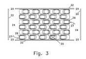
- FIG. 3is a plan view of the parking area of FIG. 1 with a cyclic shuffle step completed.
- FIG. 4is a plan view of a parking area showing vehicles parted for temporary aisle exit path. The parting is also shown as a method of accessing vehicles for loading while still in an array.
- FIG. 5is a plan view of a parking area showing vehicles parted for a diagonal exit path.
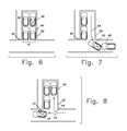
- FIG. 6is a plan view of a simple parking array with only four vehicles and central processing in a vehicle.
- FIG. 7is a plan view of the array of FIG. 6 after a request to access a vehicle is partially processed and movements are partially made.
- FIG. 8is a plan view of the array of FIG. 6 after a request to access a vehicle has completed movements and the vehicle is ready for access.
- FIG. 9is a block diagram showing the relation of the central processing, the control network and the vehicles to be controlled.
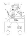
- FIG. 10is a block diagram showing the relation of components in an embodiment with central processing in a vehicle and sensors in vehicles transmitting to the central computer.
- FIG. 11is a diagram showing the relationship of sets of entities to be created as the task of accessing a vehicle or vehicles is being broken down into movements.
- FIG. 12is a plan view of the two vehicles to be built from kits in a small scale embodiment with an additional computer for use as a remote control.
- FIG. 13is a flow chart of the programming steps for a small scale embodiment.
- FIG. 14is a plan view of an embodiment of vehicles as loaded on a ferry or ship.
- FIG. 15is a plan view of vehicles ready to be loaded on a ferry or ship.
- FIG. 16is a plan view of a small scale embodiment receiving an arriving vehicle.
- FIG. 17is a plan view of a small scale embodiment finishing receiving an arriving vehicle.
- FIG. 18is a flow chart of the programming steps for a vehicle to be received in a small scale embodiment.
- FIG. 19is a flow chart of the programming steps for a blocking vehicle in a small scale embodiment.
- An autonomously driven vehicleis a vehicle which makes movements decided by a non-human decision system that is part of the vehicle. These movements may be done in the implementation of a received command to make a larger scale movement.
- An autonomously directed vehicleis a vehicle which receives and executes without human action commands to make a sequence of movements.
- the received commandmay contain sufficiently detailed information to completely define the movements or details of the exact movement may be supplied by sensors and results of processing equipment that is part of the vehicle.
- Autonomous vehiclesinclude both autonomously driven vehicles and autonomously directed vehicles. It should be noted that the computer operating an autonomous vehicle is not necessarily able to solve the many problems for use of a vehicle on public roads, but is only required to be able to command a movement or sequence of movements without human action in executing the command. Autonomous vehicles are also referred to as driverless vehicles.
- a central computeris an information processing device which directs or coordinates movements of multiple vehicles. It can be located in the vehicle storage or parking facility, remotely or in one of the vehicles.
- a column of vehiclesis a single vehicle or a group of vehicles in tandem.
- the vehiclesif more than one, are spaced substantially in the longitudinal direction, forward or backward from each other.
- the vehiclesmay not be precisely aligned in the lateral dimension. It is sufficient if they overlap enough to limit motion of at least one vehicle in the column.
- a cyclical shuffleis a rearrangement of the vehicles in a parking area or areas by moving vehicles from the front of each of one or more columns of vehicles, moving the remaining vehicles forward in their respective column or columns and placing the vehicles removed from the columns in the back of the columns.
- a markeris a device which is to be the target of a measurement or detection from a sensor. It may be optical or electronic or work in some other way. Markers include paths marked on surfaces by any means including painted lines and cables emitting electromagnetic signals. A marker can be in a fixed position or on a vehicle.
- An open shuffleis a rearrangement of the vehicles in a parking area or areas by moving vehicles from the front of each of one or more columns of vehicles, removing one or more of the moved vehicles from the parking array, moving the remaining vehicles in the columns forward in the their respective column and placing any remaining vehicles removed from the columns in the back of the columns.
- Parted vehiclesare vehicles in a parking array that have been moved to create an aisle or path for passage of a vehicle being moved or for access by a user.
- a row of vehiclesis a group of one or more vehicles side by side.
- a selected vehicleis one that is to be accessed. There are often multiple selected vehicles.
- a vehicle control networkis a communications network allowing a central vehicle control computer to command coordinated movements of multiple vehicles. It may only give destination information for relatively short movements of vehicles or it may handle two way detailed control of actuators and sensors in the vehicles.
- the vehiclesare parked in an array of closely spaced columns. Some of these columns are too closely spaced to allow access by drivers, the cargo or loading machines or personnel. Some vehicles in the columns are parked bumper to bumper so that only the first and last vehicles in the columns can move. There are access aisles at the ends of the columns leading to exits from the vehicle storage area. This situation is illustrated in FIG. 1 .
- cyclic shufflingcan be employed.
- One or more columnsare selected and one end of each column is designated as the front.
- Vehiclesare moved from the front of a column, the remaining vehicles in the column are moved forward and a vehicle from the front of a, same or different, column is put in the back of the column. This is especially effective if columns facing in opposite directions are employed to allow a short movement for the vehicle being moved.
- FIGS. 1-3The process is illustrated in FIGS. 1-3 in the simple case of employment of a pair or columns. This process, if performed twice, brings selected vehicle 20 to the end of the column from which position it can leave the array.
- Efficient access for exit of the several vehiclescan be achieved by cyclic shuffling with selected vehicles in multiple columns of a specific shuffle pattern.
- a vehicle to be accessedreaches the end of its column, it can exit and if necessary more shuffle movements can be made.
- a process to access multiple vehicles under the control of a central computercan select the columns to include in a shuffle pattern to access multiple vehicles efficiently.
- a strategy of forming temporary access aislesmay be appropriate.
- the central computercan split columns and move the portions of the vehicles in opposite directions. This is illustrated in FIG. 4 , where five columns 31 are split into subcolumns 32 .
- the resulting temporary aisle 33allows access to two vehicles in each original column for loading of cargo. Moving vehicles within the space of the original columns twice more allows access to all vehicles in the original columns at other temporary access aisles 35 .
- a parking requirementis envisioned with a small business serving a stream of autonomous vehicles bearing customers for the business.
- the businessin located in an area where space is expensive and has use of a limited parking area which is able to store only four vehicles in two closely spaced columns of two vehicles in tandem. The situation is shown in FIGS. 6 to 8 of the Drawing.
- the vehicle under autonomous controldischarges the passenger at the entrance to the walkway 42 to the business and parks in the array 41 .
- All vehicles which are permitted to use the parking arrayare enabled to communicate in a vehicle control network and be controlled by a central computer, which can be a computer in one of the controlled vehicles or in another location but is here assumed to be in the subject vehicle 20 .
- vehicles in the parking arrayuse the sensors 108 (see FIG. 10 ) provided as part of their autonomous driving equipment to determine their own location and locations of other vehicles and transmit that information to the central computer in the subject vehicle 20 .
- the central computercomputes and creates a mapping of the relative and absolute locations of vehicles to use in calculating movements.
- the central computer 101is used in various implementations to accept requests for access.
- the requestsare accumulated until a batch is formed.
- a batchmay consist of all the requests pending or a subset based on the results of an algorithm which considers urgency of request, type of request, efficiency of the batch composition for simultaneous movements or other factors in combination. Further algorithms compute a set of movements for the vehicles that will result in the desired accesses.
- the movementsare communicated to the vehicle control systems of each vehicle for execution.
- the movementsmay be transmitted in batches, movement by movement or in even smaller increments that combine to compose movements.
- Sensors to track the current location of vehiclesare used in many possible implementations to provide feedback to the central computer. They may detect presence of other vehicles or make measurements of distances from the vehicle with the sensor to another vehicle or a maker provided in the parking area. The measurements or other information provided by the sensors can be transmitted to the central computer. Some possible implementations may work in an open loop mode and rely on vehicles becoming located in the position resulting from successful execution of a commanded movement. Other implementations may use a closed loop mode and correct the position considered by the central computer as current in projecting movements based on feedback from sensors.
- Sensors located on vehiclescan be used in various ways.
- the communication path from a vehicle to the central computermay be bidirectional and return to the central computer information based on the sensors.
- the sensorsmay be used to allow the vehicle to perform operations transmitted in a high level form from the central processor by handling details and sub motions autonomously.
- the information from vehicle sensors located in multiple vehiclesmay be coordinated by the central processor to form an overall location model of a part of the vehicle array or the entire vehicle array. For example, a vehicle which is designed to function autonomously on the public roads will require sensors to measure the distance to nearby vehicles. This information can be used by the central computer to determine the relative location of not only the sensing vehicle but other nearby vehicles.
- Sensors located on vehiclesmay also be used to locate vehicles relative to fixed markers in the parking facility, the generally available Global Positioning System or a local positioning system.
- Sensors located in the array facilitymay be used to locate vehicles by sensing the vehicles or markers placed on the vehicles.
- the communication system that connects the central computermay incorporate signals, circuits or devices to measure the location of the transmission of the signals from a vehicle and may pass that information to the central computer.
- a communication systemis provided to allow the central computer to communicate movement information to vehicles.
- the systemcan be part of a vehicle control network operating only in the area of this parking system or can be a usage of a wider area communication system.
- the systemin some implementations is one way and only delivers information to the vehicles; but in many implementations it works in a bidirectional mode and delivers information from the vehicle. This information can concern the location of the vehicle, the location of other vehicles, the status of commands being received or acted upon or other data.
- Vehiclesare visualized as being in columns placed in a parking area.
- Columns of vehiclesare single vehicles or vehicles placed end to end or, equivalently, in tandem. Many of the vehicles in these columns are placed with other columns of vehicles placed sufficiently closely to prevent vehicles from leaving the column except at the ends of the columns.
- a selected vehicle in the interior portion of a columnis moved closer to an end of the column for access by moving a vehicle from the end and moving the selected vehicle and any vehicles between the selected vehicle and the end toward the end.
- the removed vehiclecan be moved to the other end of that column or to an end which has been opened in another column by moving vehicles in more than one column.
- This spacemay form an aisle to allow exit of vehicles or may be only available for longitudinal movement of vehicles in the columns. Exit can be by a vehicle turning into such an aisle or by means of a temporary aisle.
- Temporary aislescan allow access to the front or rear of vehicles adjoining the aisle and be used for loading or unloading groups of vehicles as well as for access to remove the vehicle from the array.
- FIGS. 1-5First Description of Embodiments in the Figures. ( FIGS. 1-5 )
- the vehicle depicted in the several figuresis dimensioned with values based the 2012 Toyota Prius, which is a specific common car in the marketplace.
- Various other vehicles from small model cars to large truckscould be used in similarly structured embodiments.
- This parking systemis for specially designed vehicles, it is more appropriate to base the embodiment on a specific marketplace vehicle than on the American Association of State Highway and Transportation Officials recommended vehicle commonly used for roadway design.
- the nominal space requirementis 16 by 8 feet, but in various embodiments many other sizes and types of vehicles may be used.
- the arrays shownmay be for very small vehicles, perhaps used for autonomous vehicle delivery systems, or for very large vehicles where the space savings of this approach represent substantial areas for each vehicle.
- FIGS. 1-3 described belowshow the progress of one step of a cyclical shuffle, which will, when an additional similar step is completed, bring the selected vehicle 20 to the aisle 24 for access or exit from the array.
- a parking areais shown defined by walls 22 with four openings 23 for entrance or exit and two aisles 24 .
- An array of vehicles 21is shown with 6 columns 25 and 5 vehicles in each column.
- One of the vehicles 20is marked with an “X” on its roof to designate that it is the selected vehicle for an access operation.
- FIG. 2a maneuver which forms one step of a cyclic shuffle us underway.
- Two vehicles 26have left their columns and each is proceeding toward the column left by the other on the opposite end from the exiting vehicles departure. Completed and anticipated paths are shown as 27 .
- the remaining 4 vehicles in each affected columnhave moved forward by a little more than one half of a vehicle length. In all 10 vehicles have moved, preferably at the same time and without need for a driver to access each vehicle.
- FIG. 3the maneuver of FIG. 2 . is completed.
- the two vehicles 26 which are changing columnshave arrived in their new positions.
- the remaining vehicles in the columnshave moved forward the rest of the vehicle space length to be in new spaces.
- the selected vehicle 20is one space nearer to the end of the column.
- FIGS. 1-3facing the direction in which they are to move. This is show more clearly the intended direction of movement in the maneuver being depicted. Because most vehicles are a capable of moving in reverse as in a forward direction; the direction the vehicle faces may not be material and may vary at random in the actual array of many implementations. Human operation of vehicles is much more convenient in the forward direction, but this may not be so for autonomous operation.
- an array of vehiclesis shown with five columns 31 parted by moving a portion of the vehicles toward each end wall of the parking area splitting each column into two columns 32 with a temporary aisle 33 between the new columns.
- the vehiclesare moved into the space of end aisles 24 .
- a selected vehicle 20is now accessible and is shown exiting the array by the side aisle and by path 32 .
- FIG. 4One important advantage of creating a temporary access aisle in the manner of FIG. 4 is that this aisle allows access to all of the vehicles along the aisle for adding cargo. All of the vehicles in the array can be quickly loaded in this way in preparation for rapid departure at a scheduled time.
- One such accessible vehicle 34is shown with its rear cargo door open.
- the vehicles adjoining the temporary aisleare shown pointing in directions which access to the rear of each vehicle is allowed from the temporary aisle 33 if that aisle is extended through the four unparted columns 30 .
- Additional temporary aislescould be created, one at a time, at locations 35 to allow access to additional columns of vehicles. All of the vehicles could be accessed for loading and unloading in three setups created by moving groups of vehicles. This would allow, in a preferred embodiment and usage, efficient loading of delivery cargo for rapid dispatch.
- FIG. 5the array of vehicles has been expanded with an additional column 37 and the temporary aisle 33 is now shown as a diagonal.
- the side access aisle ( 36 of FIG. 4 )is no longer available. This still allows a vehicle path 27 for the vehicle selected for access to the exit 23 .
- This extreme packing of vehiclesshows the use of these methods in situations where additional space is at an extreme premium value.
- FIG. 5also illustrates an advantage of the precision and reliability available in suitably designed automated vehicle movement because the spaces between the parted vehicles are narrow and require serpentine movements to thread the selected vehicle out of the parking array.
- FIGS. 6-11Second Description of Embodiments in the Figures—4 by 4 Parking Area.
- a small parking areais shown. It can be for a small business with a very limited allotment of parking space.
- a walkway 42brings a vehicle user 43 to call for a selected vehicle 20 .
- the selected vehicleis blocked by vehicle 40 .
- All of the vehicles in FIGS. 6-8are autonomously driven vehicles which can communicate with each other via a local or global network. Vehicles parking in array 41 are required to accept these communications and to cooperate in the execution of the method herein described.
- the sensors and computer in each vehicleare sufficient to handle the details of maneuvers in tight spaces. The driver desires to access the selected vehicle.
- the vehicle user 43 of FIG. 6has called for the selected vehicle with a device communicating over the network associated with the vehicles or otherwise reaching the selected vehicle.
- a devicecommunicating over the network associated with the vehicles or otherwise reaching the selected vehicle.
- Thiscan be done with a fixed callbox located at a convenient point or with a personal device carried by the driver.
- a computer in the selected vehicleassumes the role of a central computer as herein described.
- the central computertakes information from the sensors of the various vehicles in the parking array via the network and forms a model of the locations of the vehicles. It then forms a list of movements to be performed and transmits the relevant movements over the network to the vehicles that need to move. Blocking vehicle 40 and selected vehicle 20 in accordance with movements in the list move over path 44 to position the selected vehicle to exit the parking array
- FIG. 8the process of FIG. 7 is completed with the selected vehicle 20 in position to be entered by the user and the blocking vehicle returned to the array.
- the arraynow has a vacant space to accept a new vehicle if one comes along. It can be seen that this process requires coordinated control of multiple autonomous vehicles because of the need to move multiple vehicles from inaccessible locations.
- FIG. 9a block diagram of the overall components of a system implementing this embodiment and others is shown.
- This diagramassumes that the central computer is separate from the vehicles being controlled.
- Requests for access 100are received from a user of the system by a central computer 101 tasked with coordinating the movements of the multiple vehicles 102 in a array of vehicles.
- Requestsare processed 103 and a algorithm is applied to select a set of requests for coordinated movement.
- the set of requestsis processed 104 into a set of simultaneous and sequential movements that bring the accessed vehicles to points where access consisting of exit, loading, unloading or other operations are able to be performed.
- the movementsare transmitted to the vehicles over a communication network connecting 105 the central computer to each of the several vehicles.
- the onboard computer 107receives the movement commands.
- the commandsare processed in combination with inputs from vehicle mounted sensors 108 to produce specific motion command for motor, steering and other actuators 109 .
- the movement commandscan be implemented at different levels. They may be indirect references to locations or geometric coordinates, absolute or relative locations, specify final locations or be broken into small steps, involve one way or bidirectional communication and be either open or closed loops.
- a vehicle 106is singled out from the vehicles of the array.
- the vehicles of the array 102have local sensors 108 which can sense information about their position relative to other vehicles or to markers in the parking area.
- the vehicleshave actuators for movement and steering 109 .
- the vehicle 106is to take on the role having the central computer to control movements of itself and other vehicles in the array.
- One or more requests 100are received to access one or more vehicles in the array.
- the computer of the selected vehicle 120has or creates a model of the locations of vehicles and the parking area, which can be in various embodiments built from information acquired from local sensors, from outside sources or, here especially, from the local sensors of other vehicles in the array. This information is delivered over a communication network 121 from the other vehicles in the array.
- the central computer located in the singled out vehicleperforms the steps of FIG. 11 and send motion commands 122 to the other vehicles over the same or another network of communication links.
- Requests 100are received and handled by a process in the central computer to create a list 110 of outstanding requests.
- Repetition 111is shown for this and other list creation steps to indicate that the steps are repeated whenever new input is acquired for that stage of the overall process.
- the central computergenerates batch request lists 112 which contain one or more requests to be accessed concurrently.
- An important advantage of the method herein describedis that, if movements of vehicles are possible without physical interference, movements serving multiple access requests may be performed concurrently. It is also possible at this stage to identify in certain cases vehicle movements which will serve multiple requests. Very simple algorithms, such as adding requests as long as they do not require movements for multiple requests in the same columns, are sufficient to implement an effective system; but much more sophisticated algorithms would provide substantial improvements in efficiency.
- a processis initiated to generate a list 114 of vehicles to be moved to accomplish the goals of the batch of requests.
- the listconsists only of final positions of vehicles that are in position for access.
- the controlis then passed to a process that generates a list of movements of both the vehicles to be moved to access positions and of other vehicles that must be moved in order to accomplish that goal.
- a highly important part of this stepis to break the movement pattern down into time steps and to insure that vehicles do not interfere with each other in accomplishing the goal. Simple algorithms for this purpose will only do a few moves simultaneously thereby preventing interference. Highly sophisticated algorithms will be able to look ahead more steps and make many movements at the same time.
- a concurrent movement list 116is generated.
- the central computerthen executes movements 118 to accomplish the arrangement of vehicles for access.
- the movementscan be controlled at a finer level of detail by feedback from fixed sensors built into the parking area or from sensors in the vehicles that sense either other vehicles or markers placed in the parking area.
- the LEGO Groupproduces a robotics kit, trade named Mindstorms, of which the current basic model is their number 31313 .
- the first project recommended by the kit makeris a small vehicle 140 which has two powered wheels 141 operated by separate motors 142 and a third unpowered wheel 143 which is a castor and swivels freely on a pivot 144 .
- a programmable computer 145is included in the kit and the vehicle. It can control the motor wheels to make defined movements, take inputs from various sensors and exchange messages 146 by means of a built-in wireless facility with other nearby similar computers or an operator control.
- a fifth kitprovides an additional computer 147 of FIG. 12 for the human user to communicate as a remote control to register an access request.
- the method being described hereis the way to access a selected vehicle 20 by bringing it to the location of the passenger 43 requesting the vehicle.
- each vehiclehas an assigned parking spot and the locations of the assignments for all vehicles are in each vehicle's initial computer data.
- the four vehiclesare in two columns with two vehicles in tandem in each column spaced as closely as possible and are inaccessible as stored.
- a requestis wirelessly made by a remote control by the kit user to access selected vehicle 20 .
- the requestis wirelessly received by the computer in that vehicle.
- An ultrasonic sensor 148part of a kit or sold separately by the kit manufacturer, is mounted on vehicle 20 and determines that blocking vehicle 40 is present in the space behind vehicle 20 .
- the computer of vehicle 20assumes the role of central computer and computes a set of movements to allow the requested access. In this simple case the computation consists of selecting stored movement details from a small set of possibilities.
- the movement for blocking vehicle 40is transmitted by the wireless network from vehicle 20 to vehicle 40 and the planned movements of the two vehicles 20 and 40 are executed in coordination.
- the vehiclesmove along path 44 as shown in FIGS. 7 and 8 .
- the selected vehicleis presented for access.
- FIG. 13a flow diagram of the relevant parts of the programming is shown.
- the computers in the kitsare delivered with a graphic programming language suitable for implantation of the diagrammed steps.
- a process in the vehicle to be selectedbegins 160 and encounters a block 161 which waits for an access request.
- a user 162uses the fifth computer to send a message 162 which is received by the waiting block 161 .
- the program flowgoes to a decision block 164 which uses the ultrasonic sensor ( 148 in FIG. 12 ) to check for the presence of a blocking vehicle 40 behind the selected vehicle 20 . Because vehicles have assigned spaces the program in the computer for vehicle 20 can assume the only blocking vehicle possible is vehicle 40 in the space behind vehicle 20 .
- a block 165is executed that splits the program flow into two concurrent flows, one to make movements of the computers own vehicle 20 and one to send a message to vehicle 40 .
- the first flowexecutes two movements 166 of vehicle 20 . If the sensor check block 164 has not found a vehicle behind the original single program flow rejoins to execute these movements. This first flow then loops or stops 167 depending on the programming for other actions that are not relevant here.
- the second flow of the concurrent flow setexecutes a block 168 which transmits a message 169 to vehicle 40 and then stops 170 .
- a flow diagram of the programming for blocking vehicle 40is shown beginning at 171 and encountering a block 172 which waits for the message 169 to execute movements.
- the first rearward movementis coordinated by the message with the rearward movement of the selected vehicle 20 .
- the second forward movementmay be accompanied by a delay to allow selected vehicle 20 to be out of the way or could be coordinated by a front ultrasonic sensor similar to the rear facing sensor 148 used by selected vehicle 20 .
- the blocking vehicle programthen stops 174 .
- Central computer and network movementscan also be used to improve time, effort and space efficiency in loading a parking area with vehicles as well as in accessing vehicles.
- An embodiment of the current invention for that purposeis now described.
- the deck 200 of a vessel to carry a cargo of vehiclesis shown.
- the shapeis interrupted at several points for vehicle structure 201 and operation 202 .
- Vehicles of various types and sizeshave been loaded in close proximity and in numerous columns. The spacing is too close to allow an operator to enter or exit a vehicle in place.
- One typical driverless vehicle of each typeis labeled 203 .
- One vehicle type 204is assumed to have a human operator for each vehicle of the type. This driver, if necessary, has exited the vehicle before a neighboring vehicle was placed. This process is less efficient than driverless loading but shows that a mixed load of driverless and driver operated vehicles can be accommodated. It should be noted that some driverless vehicles, e. g. 205 , are place where complex maneuvering and sequencing are necessary in the loading process.
- a staging area 206 for the vehicles of FIG. 14is shown.
- the vehicleshave been delivered and lined up in columns for loading into the ferry.
- a specific area 207is set aside for driver operated vehicles.
- a central computeruses a network or communication links to take control of the driverless vehicles and is acquires information about the number and dimensions and maneuvering capabilities of the driver operated vehicles and the driverless vehicles. The information could come from manual entry, from pre-established databases or from the vehicles over the communication network or links.
- the computerexecutes appropriate algorithms to compute a set of locations for placing the vehicles in the ferry of FIG. 14 .
- the central computertransmits the locations to the driverless vehicles and coordinates the sequence of loading so that vehicles do not interfere with the loading of other vehicles. Locations of allowed areas for vehicles to enter or cross in reaching may be transmitted to vehicles to augment or replace information vehicles acquire from their own sensors.
- the driver operated vehicles 204leave their staging area 207 when called by a suitable communication means for drivers.
- Thismay be as simple as loudspeakers or may consist of a small device given to each driver to display directions for that specific driven vehicle.
- Driversmay be required to place their vehicles in specific places on the ferry. The places may be marked on the ferry or relative to other vehicles or designated by the direction display devices.
- the loading of driver operated vehiclesmay be before, interspersed in or after the loading of driverless vehicles.
- FIGS. 16-18Fifth Description of Embodiments in the Figures—Two by Two Area Loading ( FIGS. 16-18 )
- FIGS. 6-8 and 12 - 14are used to show an additional embodiment.
- the layouts of FIGS. 6-8 and 16 - 17are intended to show both full size vehicles in some embodiments and small vehicles built from the robotics kits in other situations.
- the movementsare the same in both cases but the vehicles and scale of the parking areas are different.
- the detailed description belowis for a small scale implementation, but it will also show the movements and operations of an implementation with full scale vehicles. It will show the loading or parking of the small scale vehicles into a small four vehicle parking area.
- Small scale vehiclesare built from the kits described in the third embodiment description and shown in FIG. 12 .
- the programming of the central computers in these vehiclesis shown in FIG. 18 .
- a vehicle 210is moved to an arrival space 212 with a fixed location incorporated in the programming of that vehicle. Because the parking spaces for the vehicles are pre-assigned, the program for arriving vehicle 210 can assume that the only blocking vehicle 40 must be considered in reaching the assigned space. The locations of the vehicles and the set of movements here required are pre-computed in the assignment of spaces and incorporated in the programs of the two vehicles involved. This pre-computation is accomplished in a separate computer which makes blocks of programs or data base entries to be stored in the central computer executing or commanding the movements. The pre-computation considers vehicle count, type, dimensions and capabilities. Blocking vehicle 40 has in its computer a variable with three states: absent, changing and present.
- Arriving vehicle 210transmits a query to blocking vehicle 40 . If the answer “changing,” arriving vehicle 210 waits as necessary while repeating the query. If the answer is “present,” the arriving vehicle's computer takes the role of central computer and transmits a message containing information requesting a movement to the blocking vehicle 40 . Blocking vehicle 40 moves backward along path 213 out of the way of arriving vehicle 210 . Thereby, executing the movement requested.
- the arriving vehicle 210executes a movement in the set of movements and moves along path 214 into its designated space 211 (shown in FIG. 16 ). Then, in coordination as established by the program in the central computer in the arriving vehicle, the blocking vehicle executes the final movement of the set of movements and return to its designated space along path 215 .
- the vehiclesare now arranged as shown in FIG. 6 as required.
- FIGS. 18 and 19Programming steps for the vehicle computers for this embodiment are shown in the depicted diagrams of FIGS. 18 and 19 . These programming steps have been compiled by a computer by an algorithm to generate appropriate steps for each combination of arriving and parked vehicles taking into account the geometry and dimensions of the parking area, the assigned spaces and the vehicles involved. Different program steps are stored in different vehicles as necessary.
- the program fragment for the arriving vehicle 210is shown starting at 220 . This is to occur when the vehicle arrives at the arrival space 212 of FIG. 16 .
- the programimmediately enters a query block 221 and repeats the query until an answer other than ‘changing’ is received to a query 222 made over the communication network or links to potential blocking vehicle 40 .
- a concurrent process 223 set blockwhich allows two processes to proceed simultaneously. It, thereby, assumes in this case the role of the central computer. Interactive processes can work in either an open loop mode as does the next step where a commanded partner is assumed to perform a commanded step after the appropriate time or in a closed loop mode where a command is followed by monitoring for confirmation of completion.
- a concurrent block 224is executed transmitting the message 225 “Back Out” is from the arriving vehicle 210 to the blocking vehicle 40 .
- the alternate concurrent block 226is a fixed interval delay to coordinate the completion of the blocking vehicle's movement along path 213 of FIG. 16 .
- the arriving vehiclethen moves according to block 227 forward along path 214 of FIG. 17 to its allotted parking space 211 .
- the one remaining step for the arriving vehicle 210is to send the message “Return Home” to the blocking vehicle 40 . This is done by block 228 which sends the message 229 to the blocking vehicle 40 .
- the programthen stops. If the reply to the query of block 221 is absent then flow skips to block 227 and the vehicle 210 moves directly into its assigned space because the blocking vehicle 40 is not in the way.
- the programming steps for the blocking vehicle 40are diagrammed.
- the vehicle's computerbegins a concurrent process set 241 for two simultaneous processes.
- the first processwhich loops continuously waits 242 for a query message 222 of FIG. 18 from another vehicle.
- the processresponds 243 .
- Message path 222is bidirectional and carries both the query to block 242 and the response from block 243 .
- the second process initiated by block 241transfers control to block 244 which waits for a message 225 “Back Out” from another vehicle.
- controlpasses to block 245 where the message is executed and a movement, along path 213 of FIG. 16 , is made which is coordinated by the central computer in the vehicle passing message 225 to the movements of the vehicle passing the message.
- the processthen waits 246 for a message “Return Home” 229 which coordinates the movement 247 of the blocking vehicle back to its assigned space along path 215 of FIG. 17 .
- the processstops at block 248 .
Landscapes
- Engineering & Computer Science (AREA)
- Automation & Control Theory (AREA)
- Architecture (AREA)
- Physics & Mathematics (AREA)
- General Physics & Mathematics (AREA)
- Mechanical Engineering (AREA)
- General Engineering & Computer Science (AREA)
- Transportation (AREA)
- Civil Engineering (AREA)
- Structural Engineering (AREA)
- Aviation & Aerospace Engineering (AREA)
- Radar, Positioning & Navigation (AREA)
- Remote Sensing (AREA)
- Control Of Position, Course, Altitude, Or Attitude Of Moving Bodies (AREA)
- Traffic Control Systems (AREA)
Abstract
Description
Claims (20)
Priority Applications (20)
| Application Number | Priority Date | Filing Date | Title |
|---|---|---|---|
| US14/611,253US9139199B2 (en) | 2015-02-01 | 2015-02-01 | Methods for dense parking of remotely controlled or autonomous vehicles |
| US14/837,114US9298186B2 (en) | 2015-02-01 | 2015-08-27 | Methods for operation of autonomous vehicles in special control zones |
| US15/043,595US9645578B2 (en) | 2015-02-01 | 2016-02-14 | Direct methods for dense parking of autonomous vehicles |
| US15/047,781US9384666B1 (en) | 2015-02-01 | 2016-02-19 | Methods to operate autonomous vehicles to pilot vehicles in groups or convoys |
| US15/171,119US9494943B2 (en) | 2015-02-01 | 2016-06-02 | Methods to operate autonomous vehicles to pilot vehicles in groups or convoys |
| US15/296,155US10216196B2 (en) | 2015-02-01 | 2016-10-18 | Methods to operate autonomous vehicles to pilot vehicles in groups or convoys |
| US16/014,675US10317913B2 (en) | 2015-02-01 | 2018-06-21 | Using pre-computed vehicle locations and paths to direct autonomous vehicle maneuvering |
| US16/014,493US10317911B2 (en) | 2015-02-01 | 2018-06-21 | Creating aisle access for autonomous vehicle parking |
| US16/014,622US10317912B2 (en) | 2015-02-01 | 2018-06-21 | Coordinating movements of autonomous vehicles for user exit, loading, or unloading |
| US16/014,458US10303182B2 (en) | 2015-02-01 | 2018-06-21 | Cyclic shuffling for autonomous vehicle parking |
| US16/014,711US10452079B2 (en) | 2015-02-01 | 2018-06-21 | Autonomous vehicle convoy communications |
| US16/014,699US10310515B2 (en) | 2015-02-01 | 2018-06-21 | Using zone rules to control autonomous vehicle operation within a zone |
| US16/014,571US10303183B2 (en) | 2015-02-01 | 2018-06-21 | Centralized mapping of autonomous vehicles to direct autonomous vehicle maneuvering |
| US16/014,585US10310514B2 (en) | 2015-02-01 | 2018-06-21 | Centralized maneuvering of autonomous vehicles for user pick-up |
| US16/547,477US11630465B2 (en) | 2015-02-01 | 2019-08-21 | Using zone rules to control autonomous vehicle operation within a zone |
| US16/567,915US11378981B2 (en) | 2015-02-01 | 2019-09-11 | Methods to operate autonomous vehicles to pilot vehicles in groups or convoys |
| US16/722,623US20200125119A1 (en) | 2015-02-01 | 2019-12-20 | Creating Aisle Access for Autonomous Vehicle Parking |
| US16/722,651US20200142430A1 (en) | 2015-02-01 | 2019-12-20 | Using Pre-Computed Vehicle Locations and Paths to Direct Autonomous Vehicle Maneuvering |
| US16/722,693US20200125120A1 (en) | 2015-02-01 | 2019-12-20 | Coordinating Movements of Autonomous Vehicles for Autonomous Vehicle Relocation |
| US16/722,590US20200125118A1 (en) | 2015-02-01 | 2019-12-20 | Coordinating Movements of Autonomous Vehicles to Direct Autonomous Vehicle Maneuvering |
Applications Claiming Priority (1)
| Application Number | Priority Date | Filing Date | Title |
|---|---|---|---|
| US14/611,253US9139199B2 (en) | 2015-02-01 | 2015-02-01 | Methods for dense parking of remotely controlled or autonomous vehicles |
Related Child Applications (3)
| Application Number | Title | Priority Date | Filing Date |
|---|---|---|---|
| US14/837,114Continuation-In-PartUS9298186B2 (en) | 2015-02-01 | 2015-08-27 | Methods for operation of autonomous vehicles in special control zones |
| US14/837,114ContinuationUS9298186B2 (en) | 2015-02-01 | 2015-08-27 | Methods for operation of autonomous vehicles in special control zones |
| US14/837,144Continuation-In-PartUS10021087B2 (en) | 2014-09-15 | 2015-08-27 | Method and system for providing a secure communication channel to portable privatized data |
Publications (2)
| Publication Number | Publication Date |
|---|---|
| US20150149022A1 US20150149022A1 (en) | 2015-05-28 |
| US9139199B2true US9139199B2 (en) | 2015-09-22 |
Family
ID=53183316
Family Applications (1)
| Application Number | Title | Priority Date | Filing Date |
|---|---|---|---|
| US14/611,253Expired - Fee RelatedUS9139199B2 (en) | 2015-02-01 | 2015-02-01 | Methods for dense parking of remotely controlled or autonomous vehicles |
Country Status (1)
| Country | Link |
|---|---|
| US (1) | US9139199B2 (en) |
Cited By (34)
| Publication number | Priority date | Publication date | Assignee | Title |
|---|---|---|---|---|
| US20160321929A1 (en)* | 2015-04-30 | 2016-11-03 | Robert Bosch Gmbh | Method and device for reducing a hazard to and/or by a vehicle situated on a parking lot |
| CN107298095A (en)* | 2016-04-14 | 2017-10-27 | 福特全球技术公司 | Autonomous vehicle stops and shifted to manual control |
| DE102016208796A1 (en)* | 2016-05-20 | 2017-11-23 | Zf Friedrichshafen Ag | Method for providing a parking strategy, system and vehicle |
| US9857796B2 (en) | 2016-05-11 | 2018-01-02 | International Business Machines Corporation | Vehicle positioning in a parking area |
| US9919704B1 (en) | 2017-01-27 | 2018-03-20 | International Business Machines Corporation | Parking for self-driving car |
| CN108505804A (en)* | 2018-04-16 | 2018-09-07 | 广东锐牛科技有限公司 | A kind of all-round streetscape parking systems can effectively ensure that safe distance |
| US10126136B2 (en) | 2016-06-14 | 2018-11-13 | nuTonomy Inc. | Route planning for an autonomous vehicle |
| US20190161121A1 (en)* | 2017-11-28 | 2019-05-30 | Jaguar Land Rover Limited | Parking assist method and apparatus |
| US10309792B2 (en) | 2016-06-14 | 2019-06-04 | nuTonomy Inc. | Route planning for an autonomous vehicle |
| US10331129B2 (en) | 2016-10-20 | 2019-06-25 | nuTonomy Inc. | Identifying a stopping place for an autonomous vehicle |
| US10338594B2 (en) | 2017-03-13 | 2019-07-02 | Nio Usa, Inc. | Navigation of autonomous vehicles to enhance safety under one or more fault conditions |
| US10363817B2 (en) | 2017-07-12 | 2019-07-30 | Ford Global Technologies, Llc | Self-loading autonomous vehicle |
| US10369974B2 (en) | 2017-07-14 | 2019-08-06 | Nio Usa, Inc. | Control and coordination of driverless fuel replenishment for autonomous vehicles |
| US10384690B2 (en) | 2017-04-03 | 2019-08-20 | nuTonomy Inc. | Processing a request signal regarding operation of an autonomous vehicle |
| US10401190B2 (en)* | 2016-04-06 | 2019-09-03 | Beijing Xiaomi Mobile Software Co., Ltd. | Vehicle control method and apparatus, and storage medium |
| US10423162B2 (en) | 2017-05-08 | 2019-09-24 | Nio Usa, Inc. | Autonomous vehicle logic to identify permissioned parking relative to multiple classes of restricted parking |
| US10453345B2 (en) | 2017-01-30 | 2019-10-22 | International Business Machines Corporation | Autonomous presentation of a self-driving vehicle |
| US10473470B2 (en) | 2016-10-20 | 2019-11-12 | nuTonomy Inc. | Identifying a stopping place for an autonomous vehicle |
| US10681513B2 (en) | 2016-10-20 | 2020-06-09 | nuTonomy Inc. | Identifying a stopping place for an autonomous vehicle |
| US10710633B2 (en) | 2017-07-14 | 2020-07-14 | Nio Usa, Inc. | Control of complex parking maneuvers and autonomous fuel replenishment of driverless vehicles |
| US10755570B1 (en) | 2019-03-05 | 2020-08-25 | Denso International America, Inc. | Systems and methods for managing a parking facility |
| US10762723B1 (en) | 2019-03-05 | 2020-09-01 | Denso International America, Inc. | Systems and methods for dynamically controlling parking rates at a parking facility |
| US10829116B2 (en) | 2016-07-01 | 2020-11-10 | nuTonomy Inc. | Affecting functions of a vehicle based on function-related information about its environment |
| US10850734B2 (en) | 2017-04-03 | 2020-12-01 | Motional Ad Llc | Processing a request signal regarding operation of an autonomous vehicle |
| US10857994B2 (en) | 2016-10-20 | 2020-12-08 | Motional Ad Llc | Identifying a stopping place for an autonomous vehicle |
| US10882521B2 (en) | 2018-02-21 | 2021-01-05 | Blackberry Limited | Method and system for use of sensors in parked vehicles for traffic safety |
| US11022971B2 (en) | 2018-01-16 | 2021-06-01 | Nio Usa, Inc. | Event data recordation to identify and resolve anomalies associated with control of driverless vehicles |
| US11036239B1 (en)* | 2016-09-08 | 2021-06-15 | Janice H. Nickel | Object identification for autonomous road vehicles |
| US11092446B2 (en) | 2016-06-14 | 2021-08-17 | Motional Ad Llc | Route planning for an autonomous vehicle |
| US11198436B2 (en) | 2017-04-03 | 2021-12-14 | Motional Ad Llc | Processing a request signal regarding operation of an autonomous vehicle |
| US11377108B2 (en) | 2017-04-03 | 2022-07-05 | Motional Ad Llc | Processing a request signal regarding operation of an autonomous vehicle |
| US11627450B2 (en) | 2016-10-20 | 2023-04-11 | Motional Ad Llc | Identifying stopping place for autonomous vehicle |
| US11663561B2 (en)* | 2017-12-29 | 2023-05-30 | Lyft, Inc. | Charge scheduling across a fleet of autonomous vehicles (AVs) |
| US12084050B1 (en) | 2020-01-30 | 2024-09-10 | Anthony J. Bourget | Autonomous vehicles, apparatuses, systems and methods |
Families Citing this family (39)
| Publication number | Priority date | Publication date | Assignee | Title |
|---|---|---|---|---|
| DE102012015922A1 (en)* | 2012-08-10 | 2014-02-13 | Daimler Ag | A method for performing a parking operation of a vehicle by means of a driver assistance system |
| DE102012021282A1 (en)* | 2012-10-29 | 2014-04-30 | Audi Ag | Method for coordinating the operation of fully automated moving vehicles |
| DE102014014136B3 (en)* | 2014-09-20 | 2016-04-07 | Audi Ag | Method and system for remotely controlling a motor vehicle |
| US9701305B2 (en)* | 2015-03-10 | 2017-07-11 | GM Global Technology Operations LLC | Automatic valet parking |
| US10023231B2 (en)* | 2015-08-12 | 2018-07-17 | Madhusoodhan Ramanujam | Parking autonomous vehicles |
| US10234859B2 (en)* | 2015-08-20 | 2019-03-19 | Harman International Industries, Incorporated | Systems and methods for driver assistance |
| DE102015216865A1 (en)* | 2015-09-03 | 2017-03-09 | Robert Bosch Gmbh | Method and device for operating a plurality of motor vehicles parked one behind the other |
| DE102015218350A1 (en) | 2015-09-24 | 2017-03-30 | Robert Bosch Gmbh | Method for parking space optimization |
| CN105464439B (en)* | 2015-12-29 | 2018-01-02 | 浙江凯达奔克起重设备有限公司 | A kind of multi-storied garage stops pick-up automated induction systems |
| EP3231690A1 (en) | 2016-04-13 | 2017-10-18 | Ford Global Technologies, LLC | Method and device for assisting a parking manoeuvre |
| DE102016207865A1 (en)* | 2016-05-09 | 2017-11-09 | Continental Automotive Gmbh | Automated parking system and method for automated parking of vehicles |
| US20170329346A1 (en)* | 2016-05-12 | 2017-11-16 | Magna Electronics Inc. | Vehicle autonomous parking system |
| US10037030B2 (en) | 2016-05-24 | 2018-07-31 | International Business Machines Corporation | Directing movement of self-driving vehicles in a delineated vehicular area |
| CN106013906B (en)* | 2016-08-03 | 2018-07-17 | 合肥协力仪表控制技术股份有限公司 | A kind of intelligent three-dimensional garage control system and control method based on CAN bus |
| JP6254665B1 (en)* | 2016-11-25 | 2017-12-27 | 本田技研工業株式会社 | Management system and program |
| CN110949392B (en)* | 2017-03-21 | 2021-04-30 | 腾讯科技(深圳)有限公司 | Vehicle control method and device |
| JP2018188873A (en)* | 2017-05-08 | 2018-11-29 | 清水建設株式会社 | Parking lot structure, parking lot management method, and parking lot management system |
| DE102017212162A1 (en)* | 2017-07-17 | 2019-01-17 | Ford Global Technologies, Llc | Method and motor vehicle for parking area optimization |
| KR20190041173A (en)* | 2017-10-12 | 2019-04-22 | 엘지전자 주식회사 | Autonomous vehicle and method of controlling the same |
| KR102370493B1 (en)* | 2017-10-30 | 2022-03-04 | 현대자동차주식회사 | System and method for sharing mobility using robot |
| US11352071B1 (en) | 2018-10-21 | 2022-06-07 | AI Incorporated | Autonomous versatile vehicle system |
| US11815894B1 (en) | 2017-12-22 | 2023-11-14 | AI Incorporated | Autonomous versatile vehicle system |
| US11091211B1 (en)* | 2017-12-22 | 2021-08-17 | AI Incorporated | Autonomous versatile vehicle system |
| US11144057B1 (en) | 2018-05-16 | 2021-10-12 | AI Incorporated | Autonomous versatile vehicle system |
| EP3614354A1 (en) | 2018-08-23 | 2020-02-26 | Volkswagen Aktiengesellschaft | Apparatus, method and computer program for a leading vehicle and a vehicle of a group of vehicles |
| US10931374B1 (en)* | 2018-12-13 | 2021-02-23 | Waymo Llc | Vehicle with free-space optical link for log data uploading |
| US11155247B1 (en) | 2019-01-10 | 2021-10-26 | AI Incorporated | Robotic towing device |
| CN111760795B (en)* | 2019-07-16 | 2022-02-01 | 北京京东乾石科技有限公司 | Method and device for sorting goods |
| DE102019215411B4 (en) | 2019-10-08 | 2022-09-29 | Continental Automotive Technologies GmbH | Procedure for driving out of a parked position autonomously |
| DE102019134309A1 (en)* | 2019-12-13 | 2021-06-17 | Valeo Schalter Und Sensoren Gmbh | METHOD OF OPERATING A VEHICLE, PARKING ASSISTANCE SYSTEM AND VEHICLE |
| US11043118B1 (en)* | 2019-12-23 | 2021-06-22 | Continental Automotive Systems, Inc. | System and method for vehicle identification |
| CN114255608A (en)* | 2020-09-19 | 2022-03-29 | 华为技术有限公司 | A parking control method and related equipment |
| CN113335270B (en)* | 2021-07-01 | 2022-05-03 | 湖南大学 | Parking path planning method and device |
| US12252172B2 (en) | 2021-09-21 | 2025-03-18 | Magna Electronics Inc. | Vehicular intelligent remote parking assist system |
| DE102021126943B4 (en) | 2021-10-18 | 2025-05-28 | Bayerische Motoren Werke Aktiengesellschaft | System for driving an automated vehicle on a moving means of transport |
| CN114954440A (en)* | 2022-07-04 | 2022-08-30 | 北京易航远智科技有限公司 | Parking method, parking system and electronic device with autonomous exploration mode |
| CN114987452B (en)* | 2022-07-19 | 2022-11-04 | 中国第一汽车股份有限公司 | Automatic parking control method and device, vehicle and storage medium |
| EP4311744A1 (en)* | 2022-07-25 | 2024-01-31 | Siemens Aktiengesellschaft | Device and method for coordinating a parking space, vehicle and parking system |
| US20240199047A1 (en)* | 2022-12-14 | 2024-06-20 | International Business Machines Corporation | Onboarding and offboarding autonomous vehicles through augmented reality |
Citations (24)
| Publication number | Priority date | Publication date | Assignee | Title |
|---|---|---|---|---|
| US5234305A (en) | 1990-12-18 | 1993-08-10 | Sogo Parking Consultants Inc. | Multi-story parking facility |
| US5367456A (en) | 1985-08-30 | 1994-11-22 | Texas Instruments Incorporated | Hierarchical control system for automatically guided vehicles |
| US5980185A (en) | 1997-07-30 | 1999-11-09 | Vita Auto Stack, Inc. | Vehicle parking structure |
| US6641351B2 (en) | 2001-04-02 | 2003-11-04 | William S. Payne | Parking garage elevator system |
| US20080122604A1 (en)* | 2006-11-29 | 2008-05-29 | Denso Corporation | Driving support apparatus |
| US20110182703A1 (en)* | 2010-01-21 | 2011-07-28 | Christopher Alan | Automated parking system |
| US8056667B2 (en) | 2008-04-22 | 2011-11-15 | GM Global Technology Operations LLC | Autonomous parking strategy based on available parking space |
| US8095273B2 (en) | 2009-10-14 | 2012-01-10 | GM Global Technology Operations LLC | Autonomous parking strategy of the vehicle with rear steer |
| US8099214B2 (en) | 2009-02-09 | 2012-01-17 | GM Global Technology Operations LLC | Path planning for autonomous parking |
| US8098174B2 (en) | 2009-04-22 | 2012-01-17 | GM Global Technology Operations LLC | Feasible region determination for autonomous parking |
| US20120072067A1 (en) | 2009-06-05 | 2012-03-22 | Valeo Schalter Und Sensoren Gmbh | Method for executing an at least semi-autonomous parking process of a vehicle and parking assistance system for a vehicle |
| US8589014B2 (en) | 2011-06-01 | 2013-11-19 | Google Inc. | Sensor field selection |
| CN103473951A (en)* | 2013-08-27 | 2013-12-25 | 东莞中国科学院云计算产业技术创新与育成中心 | Telepresence-based automatic parking lot management system |
| US20140046506A1 (en) | 2012-08-11 | 2014-02-13 | Audi Ag | Method of autonomous movement of a vehicle in a parking area |
| US20140097971A1 (en)* | 2011-03-11 | 2014-04-10 | Valeo Schalter Und Sensoren Gmbh | Method for detecting a parking space, parking assist system and motor vehicle comprising a parking assist system |
| US20140180523A1 (en) | 2012-12-22 | 2014-06-26 | Audi Ag | Driver assistance system and method for authorizing an autonomous or piloted garage parking |
| US8880270B1 (en) | 2013-01-08 | 2014-11-04 | Google Inc. | Location-aware notifications and applications for autonomous vehicles |
| US8903591B1 (en) | 2012-05-07 | 2014-12-02 | Google Inc. | Controlling a vehicle having inadequate map data |
| US20140371972A1 (en) | 2011-09-01 | 2014-12-18 | Valeo Schalter Und Sensoren Gmbh | Method for carrying out a parking process for a vehicle and driver assistance device |
| US20150039173A1 (en)* | 2013-07-31 | 2015-02-05 | Here Global B.V. | Method and appratus for causing an adjustment in parking position for vehicles |
| US20150039213A1 (en)* | 2013-08-02 | 2015-02-05 | Ford Global Technologies, Llc | Method and apparatus for autonomous movement of a parked motor vehicle |
| US20150070196A1 (en)* | 2013-09-11 | 2015-03-12 | Here Global B.V. | Method and apparatus for determining an adjustment in parking position based on proximate parked vehicle information |
| US20150078624A1 (en)* | 2012-03-30 | 2015-03-19 | Panasonic Corporation | Parking assistance device and parking assistance method |
| US20150088360A1 (en)* | 2012-04-28 | 2015-03-26 | Daimler Ag | Method for Autonomous Parking of a Motor Vehicle, Driver Assistance Device for Performing the Method and Motor Vehicle with the Driver Assistance Device |
- 2015
- 2015-02-01USUS14/611,253patent/US9139199B2/ennot_activeExpired - Fee Related
Patent Citations (24)
| Publication number | Priority date | Publication date | Assignee | Title |
|---|---|---|---|---|
| US5367456A (en) | 1985-08-30 | 1994-11-22 | Texas Instruments Incorporated | Hierarchical control system for automatically guided vehicles |
| US5234305A (en) | 1990-12-18 | 1993-08-10 | Sogo Parking Consultants Inc. | Multi-story parking facility |
| US5980185A (en) | 1997-07-30 | 1999-11-09 | Vita Auto Stack, Inc. | Vehicle parking structure |
| US6641351B2 (en) | 2001-04-02 | 2003-11-04 | William S. Payne | Parking garage elevator system |
| US20080122604A1 (en)* | 2006-11-29 | 2008-05-29 | Denso Corporation | Driving support apparatus |
| US8056667B2 (en) | 2008-04-22 | 2011-11-15 | GM Global Technology Operations LLC | Autonomous parking strategy based on available parking space |
| US8099214B2 (en) | 2009-02-09 | 2012-01-17 | GM Global Technology Operations LLC | Path planning for autonomous parking |
| US8098174B2 (en) | 2009-04-22 | 2012-01-17 | GM Global Technology Operations LLC | Feasible region determination for autonomous parking |
| US20120072067A1 (en) | 2009-06-05 | 2012-03-22 | Valeo Schalter Und Sensoren Gmbh | Method for executing an at least semi-autonomous parking process of a vehicle and parking assistance system for a vehicle |
| US8095273B2 (en) | 2009-10-14 | 2012-01-10 | GM Global Technology Operations LLC | Autonomous parking strategy of the vehicle with rear steer |
| US20110182703A1 (en)* | 2010-01-21 | 2011-07-28 | Christopher Alan | Automated parking system |
| US20140097971A1 (en)* | 2011-03-11 | 2014-04-10 | Valeo Schalter Und Sensoren Gmbh | Method for detecting a parking space, parking assist system and motor vehicle comprising a parking assist system |
| US8589014B2 (en) | 2011-06-01 | 2013-11-19 | Google Inc. | Sensor field selection |
| US20140371972A1 (en) | 2011-09-01 | 2014-12-18 | Valeo Schalter Und Sensoren Gmbh | Method for carrying out a parking process for a vehicle and driver assistance device |
| US20150078624A1 (en)* | 2012-03-30 | 2015-03-19 | Panasonic Corporation | Parking assistance device and parking assistance method |
| US20150088360A1 (en)* | 2012-04-28 | 2015-03-26 | Daimler Ag | Method for Autonomous Parking of a Motor Vehicle, Driver Assistance Device for Performing the Method and Motor Vehicle with the Driver Assistance Device |
| US8903591B1 (en) | 2012-05-07 | 2014-12-02 | Google Inc. | Controlling a vehicle having inadequate map data |
| US20140046506A1 (en) | 2012-08-11 | 2014-02-13 | Audi Ag | Method of autonomous movement of a vehicle in a parking area |
| US20140180523A1 (en) | 2012-12-22 | 2014-06-26 | Audi Ag | Driver assistance system and method for authorizing an autonomous or piloted garage parking |
| US8880270B1 (en) | 2013-01-08 | 2014-11-04 | Google Inc. | Location-aware notifications and applications for autonomous vehicles |
| US20150039173A1 (en)* | 2013-07-31 | 2015-02-05 | Here Global B.V. | Method and appratus for causing an adjustment in parking position for vehicles |
| US20150039213A1 (en)* | 2013-08-02 | 2015-02-05 | Ford Global Technologies, Llc | Method and apparatus for autonomous movement of a parked motor vehicle |
| CN103473951A (en)* | 2013-08-27 | 2013-12-25 | 东莞中国科学院云计算产业技术创新与育成中心 | Telepresence-based automatic parking lot management system |
| US20150070196A1 (en)* | 2013-09-11 | 2015-03-12 | Here Global B.V. | Method and apparatus for determining an adjustment in parking position based on proximate parked vehicle information |
Cited By (48)
| Publication number | Priority date | Publication date | Assignee | Title |
|---|---|---|---|---|
| US20160321929A1 (en)* | 2015-04-30 | 2016-11-03 | Robert Bosch Gmbh | Method and device for reducing a hazard to and/or by a vehicle situated on a parking lot |
| US9740211B2 (en)* | 2015-04-30 | 2017-08-22 | Robert Bosch Gmbh | Method and device for reducing a hazard to and/or by a vehicle situated on a parking lot |
| US10401190B2 (en)* | 2016-04-06 | 2019-09-03 | Beijing Xiaomi Mobile Software Co., Ltd. | Vehicle control method and apparatus, and storage medium |
| CN107298095A (en)* | 2016-04-14 | 2017-10-27 | 福特全球技术公司 | Autonomous vehicle stops and shifted to manual control |
| CN107298095B (en)* | 2016-04-14 | 2021-12-07 | 福特全球技术公司 | Autonomous vehicle parking and transfer to manual control |
| US9857796B2 (en) | 2016-05-11 | 2018-01-02 | International Business Machines Corporation | Vehicle positioning in a parking area |
| US10635114B2 (en) | 2016-05-11 | 2020-04-28 | International Business Machines Corporation | Optimizing space utilization |
| US10082794B2 (en) | 2016-05-11 | 2018-09-25 | International Business Machines Corporation | Vehicle positioning in a parking area |
| US10345820B2 (en) | 2016-05-11 | 2019-07-09 | International Business Machines Corporation | Optimizing space utilization |
| DE102016208796A1 (en)* | 2016-05-20 | 2017-11-23 | Zf Friedrichshafen Ag | Method for providing a parking strategy, system and vehicle |
| US11092446B2 (en) | 2016-06-14 | 2021-08-17 | Motional Ad Llc | Route planning for an autonomous vehicle |
| US10309792B2 (en) | 2016-06-14 | 2019-06-04 | nuTonomy Inc. | Route planning for an autonomous vehicle |
| US11022450B2 (en) | 2016-06-14 | 2021-06-01 | Motional Ad Llc | Route planning for an autonomous vehicle |
| US11022449B2 (en) | 2016-06-14 | 2021-06-01 | Motional Ad Llc | Route planning for an autonomous vehicle |
| US10126136B2 (en) | 2016-06-14 | 2018-11-13 | nuTonomy Inc. | Route planning for an autonomous vehicle |
| US10829116B2 (en) | 2016-07-01 | 2020-11-10 | nuTonomy Inc. | Affecting functions of a vehicle based on function-related information about its environment |
| US11036239B1 (en)* | 2016-09-08 | 2021-06-15 | Janice H. Nickel | Object identification for autonomous road vehicles |
| US10857994B2 (en) | 2016-10-20 | 2020-12-08 | Motional Ad Llc | Identifying a stopping place for an autonomous vehicle |
| US11627450B2 (en) | 2016-10-20 | 2023-04-11 | Motional Ad Llc | Identifying stopping place for autonomous vehicle |
| US10331129B2 (en) | 2016-10-20 | 2019-06-25 | nuTonomy Inc. | Identifying a stopping place for an autonomous vehicle |
| US10473470B2 (en) | 2016-10-20 | 2019-11-12 | nuTonomy Inc. | Identifying a stopping place for an autonomous vehicle |
| US11711681B2 (en) | 2016-10-20 | 2023-07-25 | Motional Ad Llc | Identifying a stopping place for an autonomous vehicle |
| US10681513B2 (en) | 2016-10-20 | 2020-06-09 | nuTonomy Inc. | Identifying a stopping place for an autonomous vehicle |
| US9919704B1 (en) | 2017-01-27 | 2018-03-20 | International Business Machines Corporation | Parking for self-driving car |
| US11663919B2 (en) | 2017-01-30 | 2023-05-30 | Maplebear Inc. | Autonomous presentation of a self-driving vehicle |
| US10580305B2 (en) | 2017-01-30 | 2020-03-03 | International Business Machines Corporation | Autonomous presentation of a self-driving vehicle |
| US10453345B2 (en) | 2017-01-30 | 2019-10-22 | International Business Machines Corporation | Autonomous presentation of a self-driving vehicle |
| US12087167B2 (en) | 2017-01-30 | 2024-09-10 | Maplebear Inc. | Autonomous presentation of a self-driving vehicle |
| US10338594B2 (en) | 2017-03-13 | 2019-07-02 | Nio Usa, Inc. | Navigation of autonomous vehicles to enhance safety under one or more fault conditions |
| US10384690B2 (en) | 2017-04-03 | 2019-08-20 | nuTonomy Inc. | Processing a request signal regarding operation of an autonomous vehicle |
| US12258029B2 (en) | 2017-04-03 | 2025-03-25 | Motional Ad Llc | Processing a request signal regarding operation of an autonomous vehicle |
| US11772669B2 (en) | 2017-04-03 | 2023-10-03 | Motional Ad Llc | Processing a request signal regarding operation of an autonomous vehicle |
| US10850734B2 (en) | 2017-04-03 | 2020-12-01 | Motional Ad Llc | Processing a request signal regarding operation of an autonomous vehicle |
| US11377108B2 (en) | 2017-04-03 | 2022-07-05 | Motional Ad Llc | Processing a request signal regarding operation of an autonomous vehicle |
| US11198436B2 (en) | 2017-04-03 | 2021-12-14 | Motional Ad Llc | Processing a request signal regarding operation of an autonomous vehicle |
| US10423162B2 (en) | 2017-05-08 | 2019-09-24 | Nio Usa, Inc. | Autonomous vehicle logic to identify permissioned parking relative to multiple classes of restricted parking |
| US10363817B2 (en) | 2017-07-12 | 2019-07-30 | Ford Global Technologies, Llc | Self-loading autonomous vehicle |
| US10710633B2 (en) | 2017-07-14 | 2020-07-14 | Nio Usa, Inc. | Control of complex parking maneuvers and autonomous fuel replenishment of driverless vehicles |
| US10369974B2 (en) | 2017-07-14 | 2019-08-06 | Nio Usa, Inc. | Control and coordination of driverless fuel replenishment for autonomous vehicles |
| US20190161121A1 (en)* | 2017-11-28 | 2019-05-30 | Jaguar Land Rover Limited | Parking assist method and apparatus |
| US11663561B2 (en)* | 2017-12-29 | 2023-05-30 | Lyft, Inc. | Charge scheduling across a fleet of autonomous vehicles (AVs) |
| US11022971B2 (en) | 2018-01-16 | 2021-06-01 | Nio Usa, Inc. | Event data recordation to identify and resolve anomalies associated with control of driverless vehicles |
| US12093042B2 (en) | 2018-01-16 | 2024-09-17 | Nio Usa, Inc. | Event data recordation to identify and resolve anomalies associated with control of driverless vehicles |
| US10882521B2 (en) | 2018-02-21 | 2021-01-05 | Blackberry Limited | Method and system for use of sensors in parked vehicles for traffic safety |
| CN108505804A (en)* | 2018-04-16 | 2018-09-07 | 广东锐牛科技有限公司 | A kind of all-round streetscape parking systems can effectively ensure that safe distance |
| US10755570B1 (en) | 2019-03-05 | 2020-08-25 | Denso International America, Inc. | Systems and methods for managing a parking facility |
| US10762723B1 (en) | 2019-03-05 | 2020-09-01 | Denso International America, Inc. | Systems and methods for dynamically controlling parking rates at a parking facility |
| US12084050B1 (en) | 2020-01-30 | 2024-09-10 | Anthony J. Bourget | Autonomous vehicles, apparatuses, systems and methods |
Also Published As
| Publication number | Publication date |
|---|---|
| US20150149022A1 (en) | 2015-05-28 |
Similar Documents
| Publication | Publication Date | Title |
|---|---|---|
| US9139199B2 (en) | Methods for dense parking of remotely controlled or autonomous vehicles | |
| US9645578B2 (en) | Direct methods for dense parking of autonomous vehicles | |
| US11378981B2 (en) | Methods to operate autonomous vehicles to pilot vehicles in groups or convoys | |
| US9494943B2 (en) | Methods to operate autonomous vehicles to pilot vehicles in groups or convoys | |
| JP7669451B2 (en) | Information processing device, information processing method, computer program, and information processing system | |
| CN105882653A (en) | Method and device for ascertaining a parking position for a vehicle | |
| IE891429L (en) | Automated vehicle control | |
| US20250223142A1 (en) | Lane grid setup for autonomous mobile robot | |
| Hoffman et al. | A multi-track elevator system for E-commerce fulfillment centers | |
| US20240152148A1 (en) | System and method for optimized traffic flow through intersections with conditional convoying based on path network analysis | |
| TROVATO | General Planning Method for Machine Coordination and Rendezvous | |
| TROVATO | GENERAL METHOD FOR PLANNING AND RENDEZVOUS PROBLEMS | |
| Nooyens | The Influence of Intersection Strategies of Autonomous Terminal Tractor-Only Intersections on the Productivity of an RTG-based Container Terminal |
Legal Events
| Date | Code | Title | Description |
|---|---|---|---|
| STCF | Information on status: patent grant | Free format text:PATENTED CASE | |
| AS | Assignment | Owner name:PROSPER TECHNOLOGY, LLC, DELAWARE Free format text:ASSIGNMENT OF ASSIGNORS INTEREST;ASSIGNOR:HARVEY, THOMAS DANAHER;REEL/FRAME:044315/0111 Effective date:20171128 | |
| AS | Assignment | Owner name:LYFT, INC., CALIFORNIA Free format text:ASSIGNMENT OF ASSIGNORS INTEREST;ASSIGNOR:PROSPER TECHNOLOGY, LLC;REEL/FRAME:048063/0217 Effective date:20190118 | |
| FEPP | Fee payment procedure | Free format text:ENTITY STATUS SET TO UNDISCOUNTED (ORIGINAL EVENT CODE: BIG.); ENTITY STATUS OF PATENT OWNER: LARGE ENTITY | |
| MAFP | Maintenance fee payment | Free format text:PAYMENT OF MAINTENANCE FEE, 4TH YEAR, LARGE ENTITY (ORIGINAL EVENT CODE: M1551); ENTITY STATUS OF PATENT OWNER: LARGE ENTITY Year of fee payment:4 | |
| AS | Assignment | Owner name:JPMORGAN CHASE BANK, N.A., AS ADMINISTRATIVE AGENT, NEW YORK Free format text:SECURITY INTEREST;ASSIGNOR:LYFT, INC.;REEL/FRAME:061880/0237 Effective date:20221103 | |
| FEPP | Fee payment procedure | Free format text:MAINTENANCE FEE REMINDER MAILED (ORIGINAL EVENT CODE: REM.); ENTITY STATUS OF PATENT OWNER: LARGE ENTITY | |
| LAPS | Lapse for failure to pay maintenance fees | Free format text:PATENT EXPIRED FOR FAILURE TO PAY MAINTENANCE FEES (ORIGINAL EVENT CODE: EXP.); ENTITY STATUS OF PATENT OWNER: LARGE ENTITY | |
| STCH | Information on status: patent discontinuation | Free format text:PATENT EXPIRED DUE TO NONPAYMENT OF MAINTENANCE FEES UNDER 37 CFR 1.362 | |
| FP | Lapsed due to failure to pay maintenance fee | Effective date:20230922 |