US9138821B2 - Methods for simultaneously brazing a ferrule and lead pins - Google Patents
Methods for simultaneously brazing a ferrule and lead pinsDownload PDFInfo
- Publication number
- US9138821B2 US9138821B2US14/260,401US201414260401AUS9138821B2US 9138821 B2US9138821 B2US 9138821B2US 201414260401 AUS201414260401 AUS 201414260401AUS 9138821 B2US9138821 B2US 9138821B2
- Authority
- US
- United States
- Prior art keywords
- lead pin
- ceramic insulator
- feedthrough
- ferrule
- fixture
- Prior art date
- Legal status (The legal status is an assumption and is not a legal conclusion. Google has not performed a legal analysis and makes no representation as to the accuracy of the status listed.)
- Active
Links
- 238000005219brazingMethods0.000titleclaimsabstractdescription10
- 238000000034methodMethods0.000titleclaimsdescription22
- 239000012212insulatorSubstances0.000claimsabstractdescription57
- 239000000919ceramicSubstances0.000claimsabstractdescription50
- 238000003780insertionMethods0.000claimsdescription10
- 230000037431insertionEffects0.000claimsdescription10
- 238000010438heat treatmentMethods0.000claimsdescription5
- 239000002184metalSubstances0.000abstract1
- 239000000463materialSubstances0.000description12
- 238000000429assemblyMethods0.000description8
- 230000000712assemblyEffects0.000description8
- BASFCYQUMIYNBI-UHFFFAOYSA-NplatinumChemical compound[Pt]BASFCYQUMIYNBI-UHFFFAOYSA-N0.000description6
- PNEYBMLMFCGWSK-UHFFFAOYSA-Naluminium oxideInorganic materials[O-2].[O-2].[O-2].[Al+3].[Al+3]PNEYBMLMFCGWSK-UHFFFAOYSA-N0.000description3
- 230000001419dependent effectEffects0.000description3
- 229910052697platinumInorganic materials0.000description3
- RTAQQCXQSZGOHL-UHFFFAOYSA-NTitaniumChemical compound[Ti]RTAQQCXQSZGOHL-UHFFFAOYSA-N0.000description2
- 229910045601alloyInorganic materials0.000description2
- 239000000956alloySubstances0.000description2
- 229910010293ceramic materialInorganic materials0.000description2
- 230000013011matingEffects0.000description2
- 229910052758niobiumInorganic materials0.000description2
- 239000010955niobiumSubstances0.000description2
- GUCVJGMIXFAOAE-UHFFFAOYSA-Nniobium atomChemical compound[Nb]GUCVJGMIXFAOAE-UHFFFAOYSA-N0.000description2
- TWNQGVIAIRXVLR-UHFFFAOYSA-Noxo(oxoalumanyloxy)alumaneChemical compoundO=[Al]O[Al]=OTWNQGVIAIRXVLR-UHFFFAOYSA-N0.000description2
- HBMJWWWQQXIZIP-UHFFFAOYSA-Nsilicon carbideChemical compound[Si+]#[C-]HBMJWWWQQXIZIP-UHFFFAOYSA-N0.000description2
- 229910010271silicon carbideInorganic materials0.000description2
- 239000010936titaniumSubstances0.000description2
- 229910052719titaniumInorganic materials0.000description2
- OKTJSMMVPCPJKN-UHFFFAOYSA-NCarbonChemical compound[C]OKTJSMMVPCPJKN-UHFFFAOYSA-N0.000description1
- 229910052581Si3N4Inorganic materials0.000description1
- GWEVSGVZZGPLCZ-UHFFFAOYSA-NTitan oxideChemical compoundO=[Ti]=OGWEVSGVZZGPLCZ-UHFFFAOYSA-N0.000description1
- 229910052593corundumInorganic materials0.000description1
- 239000010431corundumSubstances0.000description1
- 239000006260foamSubstances0.000description1
- PCHJSUWPFVWCPO-UHFFFAOYSA-NgoldChemical compound[Au]PCHJSUWPFVWCPO-UHFFFAOYSA-N0.000description1
- 229910052737goldInorganic materials0.000description1
- 239000010931goldSubstances0.000description1
- 229910002804graphiteInorganic materials0.000description1
- 239000010439graphiteSubstances0.000description1
- 238000003754machiningMethods0.000description1
- 238000002844meltingMethods0.000description1
- 230000008018meltingEffects0.000description1
- 238000000465mouldingMethods0.000description1
- HWLDNSXPUQTBOD-UHFFFAOYSA-Nplatinum-iridium alloyChemical class[Ir].[Pt]HWLDNSXPUQTBOD-UHFFFAOYSA-N0.000description1
- HQVNEWCFYHHQES-UHFFFAOYSA-Nsilicon nitrideChemical compoundN12[Si]34N5[Si]62N3[Si]51N64HQVNEWCFYHHQES-UHFFFAOYSA-N0.000description1
- 239000000758substrateSubstances0.000description1
- OGIDPMRJRNCKJF-UHFFFAOYSA-Ntitanium oxideInorganic materials[Ti]=OOGIDPMRJRNCKJF-UHFFFAOYSA-N0.000description1
- 238000003466weldingMethods0.000description1
Images


Classifications
- B—PERFORMING OPERATIONS; TRANSPORTING
- B23—MACHINE TOOLS; METAL-WORKING NOT OTHERWISE PROVIDED FOR
- B23K—SOLDERING OR UNSOLDERING; WELDING; CLADDING OR PLATING BY SOLDERING OR WELDING; CUTTING BY APPLYING HEAT LOCALLY, e.g. FLAME CUTTING; WORKING BY LASER BEAM
- B23K1/00—Soldering, e.g. brazing, or unsoldering
- B23K1/0008—Soldering, e.g. brazing, or unsoldering specially adapted for particular articles or work
- B23K1/0016—Brazing of electronic components
- B—PERFORMING OPERATIONS; TRANSPORTING
- B23—MACHINE TOOLS; METAL-WORKING NOT OTHERWISE PROVIDED FOR
- B23K—SOLDERING OR UNSOLDERING; WELDING; CLADDING OR PLATING BY SOLDERING OR WELDING; CUTTING BY APPLYING HEAT LOCALLY, e.g. FLAME CUTTING; WORKING BY LASER BEAM
- B23K1/00—Soldering, e.g. brazing, or unsoldering
- B23K1/008—Soldering within a furnace
- B—PERFORMING OPERATIONS; TRANSPORTING
- B23—MACHINE TOOLS; METAL-WORKING NOT OTHERWISE PROVIDED FOR
- B23K—SOLDERING OR UNSOLDERING; WELDING; CLADDING OR PLATING BY SOLDERING OR WELDING; CUTTING BY APPLYING HEAT LOCALLY, e.g. FLAME CUTTING; WORKING BY LASER BEAM
- B23K3/00—Tools, devices, or special appurtenances for soldering, e.g. brazing, or unsoldering, not specially adapted for particular methods
- B23K3/06—Solder feeding devices; Solder melting pans
- B23K3/0607—Solder feeding devices
- B23K3/0623—Solder feeding devices for shaped solder piece feeding, e.g. preforms, bumps, balls, pellets, droplets
- B—PERFORMING OPERATIONS; TRANSPORTING
- B23—MACHINE TOOLS; METAL-WORKING NOT OTHERWISE PROVIDED FOR
- B23K—SOLDERING OR UNSOLDERING; WELDING; CLADDING OR PLATING BY SOLDERING OR WELDING; CUTTING BY APPLYING HEAT LOCALLY, e.g. FLAME CUTTING; WORKING BY LASER BEAM
- B23K37/00—Auxiliary devices or processes, not specially adapted for a procedure covered by only one of the other main groups of this subclass
- B23K37/04—Auxiliary devices or processes, not specially adapted for a procedure covered by only one of the other main groups of this subclass for holding or positioning work
- B23K37/0426—Fixtures for other work
- B23K37/0435—Clamps
- H—ELECTRICITY
- H01—ELECTRIC ELEMENTS
- H01G—CAPACITORS; CAPACITORS, RECTIFIERS, DETECTORS, SWITCHING DEVICES, LIGHT-SENSITIVE OR TEMPERATURE-SENSITIVE DEVICES OF THE ELECTROLYTIC TYPE
- H01G4/00—Fixed capacitors; Processes of their manufacture
- H01G4/35—Feed-through capacitors or anti-noise capacitors
- H—ELECTRICITY
- H01—ELECTRIC ELEMENTS
- H01R—ELECTRICALLY-CONDUCTIVE CONNECTIONS; STRUCTURAL ASSOCIATIONS OF A PLURALITY OF MUTUALLY-INSULATED ELECTRICAL CONNECTING ELEMENTS; COUPLING DEVICES; CURRENT COLLECTORS
- H01R4/00—Electrically-conductive connections between two or more conductive members in direct contact, i.e. touching one another; Means for effecting or maintaining such contact; Electrically-conductive connections having two or more spaced connecting locations for conductors and using contact members penetrating insulation
- H01R4/02—Soldered or welded connections
- H01R4/027—Soldered or welded connections comprising means for positioning or holding the parts to be soldered or welded
- H—ELECTRICITY
- H01—ELECTRIC ELEMENTS
- H01R—ELECTRICALLY-CONDUCTIVE CONNECTIONS; STRUCTURAL ASSOCIATIONS OF A PLURALITY OF MUTUALLY-INSULATED ELECTRICAL CONNECTING ELEMENTS; COUPLING DEVICES; CURRENT COLLECTORS
- H01R43/00—Apparatus or processes specially adapted for manufacturing, assembling, maintaining, or repairing of line connectors or current collectors or for joining electric conductors
- H01R43/02—Apparatus or processes specially adapted for manufacturing, assembling, maintaining, or repairing of line connectors or current collectors or for joining electric conductors for soldered or welded connections
- H01R43/0249—Apparatus or processes specially adapted for manufacturing, assembling, maintaining, or repairing of line connectors or current collectors or for joining electric conductors for soldered or welded connections for simultaneous welding or soldering of a plurality of wires to contact elements
- H—ELECTRICITY
- H01—ELECTRIC ELEMENTS
- H01R—ELECTRICALLY-CONDUCTIVE CONNECTIONS; STRUCTURAL ASSOCIATIONS OF A PLURALITY OF MUTUALLY-INSULATED ELECTRICAL CONNECTING ELEMENTS; COUPLING DEVICES; CURRENT COLLECTORS
- H01R43/00—Apparatus or processes specially adapted for manufacturing, assembling, maintaining, or repairing of line connectors or current collectors or for joining electric conductors
- H01R43/20—Apparatus or processes specially adapted for manufacturing, assembling, maintaining, or repairing of line connectors or current collectors or for joining electric conductors for assembling or disassembling contact members with insulating base, case or sleeve
- B—PERFORMING OPERATIONS; TRANSPORTING
- B23—MACHINE TOOLS; METAL-WORKING NOT OTHERWISE PROVIDED FOR
- B23K—SOLDERING OR UNSOLDERING; WELDING; CLADDING OR PLATING BY SOLDERING OR WELDING; CUTTING BY APPLYING HEAT LOCALLY, e.g. FLAME CUTTING; WORKING BY LASER BEAM
- B23K2101/00—Articles made by soldering, welding or cutting
- B23K2101/36—Electric or electronic devices
- B23K2101/38—Conductors
Definitions
- the disclosureis related to methods of making feedthrough interconnects for electrical devices, for example, medical devices.
- the disclosurealso is related to assemblies used in the methods of making such feedthrough interconnects.
- a method for making a brazed feedthroughincludes simultaneously brazing a ferrule to an insulator and lead pins to pads on the insulator using braze preforms.
- the methodincludes providing a freestanding lead pin fixture comprising a plurality of lead pin fixture holes through the lead pin fixture, the holes configured to accept insertion of the at least one lead pin, the freestanding lead pin fixture configured to be placed over the feedthrough such that the at least one fixtured lead pin and a braze preform are aligned and in contact with the contact pad on the surface of the ceramic insulator, inserting at least one lead pin into a hole in the lead pin fixture, placing said freestanding lead pin fixture over the feedthrough such that the at least one fixtured lead pin and the braze preform are aligned and in contact with the contact pad on the surface of the ceramic insulator to form a feedthrough assembly, and heating the feedthrough assembly at a temperature and for a time sufficient to form brazed joints between the ferrule and the ceramic insulator and the
- the braze preformmay be attached to the head of a lead pin or the braze preform can be placed on the contact pad on the surface of the ceramic insulator before the fixtured lead pin in the lead pin fixture is aligned with the contact pad and ceramic insulator, respectively.
- an assemblycomprises a lead pin fixture comprising a feedthrough insertion cutout and a plurality of lead pin fixture holes through the lead pin fixture, and at least one lead pin fit within one of the plurality of lead pin fixture holes, the at least one lead pin having a proximate end of the lead pin, and a feedthrough fitted within the feedthrough insertion cutout of the lead pin fixture and comprising a ceramic insulator having at least one conductive via, the at least one via having a contact pad on a surface of the ceramic insulator, a lead pin braze preform between and contacting the contact pad and the proximate end of the at least one lead pin, a ferrule surrounding the ceramic insulator and a ferrule braze preform around the ceramic insulator and between the ferrule and the ceramic insulator.
- FIG. 1is a depiction of an exploded view of an embodiment of a feedthrough assembly and a lead pin fixture prior to assembly;
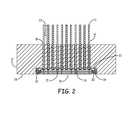
- FIG. 2is a depiction of an assembled feedthrough assembly and lead pin fixture in cross-section
- FIG. 3is a depiction of a clamp holding the distal fee ends of the pins after the lead pins have been inserted into a freestanding lead pin fixture.
- feedthrough assemblies described in this applicationare typically used within implantable medical devices to provide electrical connections from within a hermetically sealed medical device or component of a medical device, to the exterior of the medical device or medical device component. These are also known as “interconnects”.
- the methods and assemblies described in this applicationallow simultaneous brazing of a ferrule to an insulator and the lead pins to contact pads on a surface of the insulator.
- a lead pin fixtureis used to provide repeatable alignment of the feedthrough pins with the contact pads on the insulator or feedthrough. Multiple assemblies can be used to make multiple finished feedthrough assemblies simultaneously.
- FIG. 1is an exploded view of a feedthrough interconnect or assembly 10 and a lead pin fixture 12 prior to assembly and brazing.
- feed through assembly 10comprises at least one feedthrough pin 14 and a feedthrough 16 .
- Feedthrough 16comprises a ceramic insulator 18 having at least one conductive via 17 and at least one contact pad 20 attached to the conductive via and present at the surface of the ceramic insulator.
- Surrounding the ceramic insulatoris a ferrule 19 .
- Feedthrough assembly 10further includes a lead pin braze preform 22 on each of the heads 13 of lead pins 14 to be brazed and a ferrule braze preform 24 adapted to be placed around the ceramic insulator between the ceramic insulator 18 and the ferrule 19 .
- the lead pin braze preforms 22may be placed onto the contact pads 20 and then mated to the heads 13 of the lead pins 14 .
- freestanding lead pin fixture 12is configured to align and support lead pins 14 within lead pin fixture holes 15 such that the preforms 22 attached to the heads 13 of the pins 14 align with the conductive contact pads 20 of the ceramic insulator 18 .
- Lead pin fixture 12is also configured to accept feedthrough 16 within an indention or cutout 21 in the lead pin fixture.
- cutout 21has dimensions such that feedthrough 16 fits within the cutout 21 and the bottom surface 26 of the feedthrough is substantially aligned with the bottom surface 28 of the lead pin fixture for placement of the combined feedthrough assembly 10 and lead pin fixture 12 onto a substrate before heating the combined assembly to melt the braze preforms and form braze joints between the ferrule and the ceramic insulator and the at least one lead pin and the contact pad.
- feedthrough bottom surface 26 and lead pin fixture bottom surface 28are not substantially aligned. Alignment or non-alignment is dependent upon the particular feed through design. Distal ends 11 of lead pins and distal portions 23 of lead pins extend outwardly from the lead pin fixture and out of the lead pin fixture holes 15 .
- the feedthrough 16is substantially rectangular in shape.
- the shape of the cutout 21 in the lead pin fixture 12is substantially dependent upon the shape of the feedthrough.
- the shape of the feedthroughcan be almost any shape including the shape of a square, a circle, an oval, a cylinder, an ellipse, or a triangle, including shapes that are substantially the shape of any of the previously mentioned shapes.
- the shape of the corresponding cutout in the lead pin fixturecan be any shape which accepts a feedthrough having a given shape and which substantially aligns the heads of the feedthrough pins with the contact pads on the ceramic insulator of the feedthrough.
- the brazing preformstypically comprise gold.
- the lead pinsare made from niobium and alloys containing niobium. Other useful materials include platinum and platinum-iridium alloys.
- the number of lead pinscan vary from 1 to 20 or more. In other embodiments, the number of lead pins can be 1, 2, 3, 4, 5, 6, 7, 8, 9, 10, 11, 12, 13, 14, 15, 16 17, 18 or 19.
- the lead pinshave a diameter of about 0.38 mm and the lead pin heads typically have diameters that range from 0.5 to 0.8 mm.
- the conductive vias and the contact padsare made of platinum and alloys containing platinum.
- the conductive contact padscan be any shape and are typically square or round in shape.
- the ceramic insulator 18is primarily formed from a material that is generally electrically non-conductive, an insulator, or a dielectric.
- the ceramic insulatorfurther includes one or more conductive vias 17 having contact pads 20 that are generally electrically conductive and that extend through the ceramic insulator that is generally electrically non-conductive.
- the vias 17are integrated with the ceramic insulator 18 but do not extend directly through, and instead extend through the insulator by a tortuous path.
- the ceramic material used to make the ceramic insulatorincludes alumina (e.g., aluminum oxide, corundum), such as at least 70% alumina or about 92% or 96% alumina.
- aluminae.g., aluminum oxide, corundum
- the ceramic materialis formed or molded and a metallic paste is placed into holes in the ‘green’ molded ceramic insulator to form the vias and contact pads.
- the assemblyis then co-fired together in a kiln to form the finished ceramic insulator or “co-fire feedthrough”.
- the ferrule 19is made from a material that comprises titanium. Examples of the materials and processes used to make feedthroughs that can be used in the processes disclosed in this application can be found in U.S. Pat. No. 8,588,916, incorporated by reference for the description of materials and processes used to make such feedthroughs.
- the lead pin fixturecan be made of any material that is resistant to the temperatures required for melting the braze preform materials.
- Useful materialsinclude graphite (typically coated with silicon carbide or titanium oxide), aluminum oxide, silicon carbide, silicon nitride and combinations thereof.
- the lead pin fixtureis made from a material or is coated with a material that is unreactive with titanium.
- the lead pin fixturescan be made by molding or machining techniques or a combination of both.
- the shape of the lead pin fixtureis substantially rectangular and has a thickness having a dimension greater than the width of the feedthrough.
- the feedthrough insertion indention or cutout in the lead pin fixturehas dimensions adapted to accept the dimensions of the feedthrough and align the conductive contact pads of the feedthrough with the preform-capped heads of the lead pins that are held within the holes in the lead pin fixture.
- the interior surface of the cutoutis designed to mate with the exterior features or design of the ferrule. Such mating features are designed to ensure alignment of the feedthrough and contact pads with the preform-capped heads of the lead pins and to minimize errors in assembly. Such mating features could be unique for different feedthroughs and lead pin fixtures to help ensure that the correct feedthroughs are brazed to the correct lead pins.
- lead pin braze preformsare formed, typically by stamping and then cold pressed onto the heads of the lead pins.
- the lead pin braze preformscould also be attached by laser or resistance-spot welding methods. Applicants have found that for a lead pin head having a size or area of about 0.3 mm2 the approximate amount of preform material required to form a robust braze joint is about 4.1 ⁇ 10-5 cm3.
- the area of the lead pin headsmay typically range from about 0.2 mm2 to about 0.5 mm2, including any area or range of areas within such range.
- the distal ends of the lead pinsare inserted into the lead pin fixture holes that are within the cutout in the lead pin fixture.
- the lead pin fixtureis stored on its side to keep the lead pins in place.
- the free ends of the lead pins 14are held in place by hand or a clamp 29 and the free end of the lead pins is released after the lead pin fixture 12 is aligned and placed over the feedthrough.
- Clamp 29is in the form of a pliers-type clamp having a foam or other shape compliant grip so as to not damage the free ends of the pins.
- the lead pin braze preformsare placed onto the contact pads, the distal ends of the lead pins are inserted into the lead pin fixture holes that are within the cutout in the lead pin fixture, and the heads of the lead pins are mated with or contact the lead pin braze preforms.
- the lead pin fixtureis stored on its side to keep the lead pins in place.
- the free end of the lead pinsis held in place by hand or a clamp and the free end of the lead pins is released after the lead pin fixture is aligned and placed over the feedthrough.
- the ferrule braze preformis typically formed by stamping.
- the shape of the ferrule braze preformis dependent upon the shape and dimensions of the ceramic insulator and the surrounding ferrule.
- the entire assemblyis heated to melt the braze preform material to form brazed joints between the ferrule and the ceramic insulator and the at least one lead pin and the contact pad simultaneously and in one heating or brazing step.
- the assembliesare heated within a vacuum furnace set at a temperature of about 1085° C., or a range from about 1000-1150° C. for approximately 1 minute, and then allowed to cool to room temperature.
Landscapes
- Engineering & Computer Science (AREA)
- Mechanical Engineering (AREA)
- Manufacturing & Machinery (AREA)
- Physics & Mathematics (AREA)
- Optics & Photonics (AREA)
- Power Engineering (AREA)
- Microelectronics & Electronic Packaging (AREA)
- Resistance Heating (AREA)
- Ceramic Products (AREA)
Abstract
Description
The disclosure is related to methods of making feedthrough interconnects for electrical devices, for example, medical devices. The disclosure also is related to assemblies used in the methods of making such feedthrough interconnects.
In one embodiment, a method for making a brazed feedthrough is described. The method includes simultaneously brazing a ferrule to an insulator and lead pins to pads on the insulator using braze preforms. The method includes providing a freestanding lead pin fixture comprising a plurality of lead pin fixture holes through the lead pin fixture, the holes configured to accept insertion of the at least one lead pin, the freestanding lead pin fixture configured to be placed over the feedthrough such that the at least one fixtured lead pin and a braze preform are aligned and in contact with the contact pad on the surface of the ceramic insulator, inserting at least one lead pin into a hole in the lead pin fixture, placing said freestanding lead pin fixture over the feedthrough such that the at least one fixtured lead pin and the braze preform are aligned and in contact with the contact pad on the surface of the ceramic insulator to form a feedthrough assembly, and heating the feedthrough assembly at a temperature and for a time sufficient to form brazed joints between the ferrule and the ceramic insulator and the at least one lead pin and the contact pad.
In another aspect of the method above, the braze preform may be attached to the head of a lead pin or the braze preform can be placed on the contact pad on the surface of the ceramic insulator before the fixtured lead pin in the lead pin fixture is aligned with the contact pad and ceramic insulator, respectively.
In another embodiment, an assembly comprises a lead pin fixture comprising a feedthrough insertion cutout and a plurality of lead pin fixture holes through the lead pin fixture, and at least one lead pin fit within one of the plurality of lead pin fixture holes, the at least one lead pin having a proximate end of the lead pin, and a feedthrough fitted within the feedthrough insertion cutout of the lead pin fixture and comprising a ceramic insulator having at least one conductive via, the at least one via having a contact pad on a surface of the ceramic insulator, a lead pin braze preform between and contacting the contact pad and the proximate end of the at least one lead pin, a ferrule surrounding the ceramic insulator and a ferrule braze preform around the ceramic insulator and between the ferrule and the ceramic insulator.
Methods and assemblies used for constructing or making feedthrough assemblies are described. Such feedthrough assemblies described in this application are typically used within implantable medical devices to provide electrical connections from within a hermetically sealed medical device or component of a medical device, to the exterior of the medical device or medical device component. These are also known as “interconnects”. The methods and assemblies described in this application allow simultaneous brazing of a ferrule to an insulator and the lead pins to contact pads on a surface of the insulator. A lead pin fixture is used to provide repeatable alignment of the feedthrough pins with the contact pads on the insulator or feedthrough. Multiple assemblies can be used to make multiple finished feedthrough assemblies simultaneously.
As shown inFIG. 2 , freestandinglead pin fixture 12 is configured to align and supportlead pins 14 within leadpin fixture holes 15 such that thepreforms 22 attached to theheads 13 of thepins 14 align with theconductive contact pads 20 of theceramic insulator 18.Lead pin fixture 12 is also configured to acceptfeedthrough 16 within an indention orcutout 21 in the lead pin fixture. In this embodiment,cutout 21 has dimensions such thatfeedthrough 16 fits within thecutout 21 and thebottom surface 26 of the feedthrough is substantially aligned with thebottom surface 28 of the lead pin fixture for placement of the combinedfeedthrough assembly 10 andlead pin fixture 12 onto a substrate before heating the combined assembly to melt the braze preforms and form braze joints between the ferrule and the ceramic insulator and the at least one lead pin and the contact pad. In other embodiments,feedthrough bottom surface 26 and lead pinfixture bottom surface 28 are not substantially aligned. Alignment or non-alignment is dependent upon the particular feed through design.Distal ends 11 of lead pins anddistal portions 23 of lead pins extend outwardly from the lead pin fixture and out of the leadpin fixture holes 15.
In the embodiments shown inFIGS. 1 and 2 , thefeedthrough 16 is substantially rectangular in shape. In these embodiments, the shape of thecutout 21 in thelead pin fixture 12 is substantially dependent upon the shape of the feedthrough. In other embodiments, the shape of the feedthrough can be almost any shape including the shape of a square, a circle, an oval, a cylinder, an ellipse, or a triangle, including shapes that are substantially the shape of any of the previously mentioned shapes. Similarly, the shape of the corresponding cutout in the lead pin fixture can be any shape which accepts a feedthrough having a given shape and which substantially aligns the heads of the feedthrough pins with the contact pads on the ceramic insulator of the feedthrough.
The brazing preforms typically comprise gold.
Typically the lead pins are made from niobium and alloys containing niobium. Other useful materials include platinum and platinum-iridium alloys. The number of lead pins can vary from 1 to 20 or more. In other embodiments, the number of lead pins can be 1, 2, 3, 4, 5, 6, 7, 8, 9, 10, 11, 12, 13, 14, 15, 16 17, 18 or 19. Typically, the lead pins have a diameter of about 0.38 mm and the lead pin heads typically have diameters that range from 0.5 to 0.8 mm.
Typically the conductive vias and the contact pads are made of platinum and alloys containing platinum. The conductive contact pads can be any shape and are typically square or round in shape.
Typically, theceramic insulator 18 is primarily formed from a material that is generally electrically non-conductive, an insulator, or a dielectric. The ceramic insulator further includes one or moreconductive vias 17 havingcontact pads 20 that are generally electrically conductive and that extend through the ceramic insulator that is generally electrically non-conductive. In other embodiments, thevias 17 are integrated with theceramic insulator 18 but do not extend directly through, and instead extend through the insulator by a tortuous path.
Typically, the ceramic material used to make the ceramic insulator includes alumina (e.g., aluminum oxide, corundum), such as at least 70% alumina or about 92% or 96% alumina. The ceramic material is formed or molded and a metallic paste is placed into holes in the ‘green’ molded ceramic insulator to form the vias and contact pads. The assembly is then co-fired together in a kiln to form the finished ceramic insulator or “co-fire feedthrough”. Typically, theferrule 19 is made from a material that comprises titanium. Examples of the materials and processes used to make feedthroughs that can be used in the processes disclosed in this application can be found in U.S. Pat. No. 8,588,916, incorporated by reference for the description of materials and processes used to make such feedthroughs.
The lead pin fixture can be made of any material that is resistant to the temperatures required for melting the braze preform materials. Useful materials include graphite (typically coated with silicon carbide or titanium oxide), aluminum oxide, silicon carbide, silicon nitride and combinations thereof. Typically, the lead pin fixture is made from a material or is coated with a material that is unreactive with titanium. The lead pin fixtures can be made by molding or machining techniques or a combination of both.
In the embodiment shown inFIGS. 1 and 2 the shape of the lead pin fixture is substantially rectangular and has a thickness having a dimension greater than the width of the feedthrough. The feedthrough insertion indention or cutout in the lead pin fixture has dimensions adapted to accept the dimensions of the feedthrough and align the conductive contact pads of the feedthrough with the preform-capped heads of the lead pins that are held within the holes in the lead pin fixture. In the embodiment shown inFIG. 2 , the interior surface of the cutout is designed to mate with the exterior features or design of the ferrule. Such mating features are designed to ensure alignment of the feedthrough and contact pads with the preform-capped heads of the lead pins and to minimize errors in assembly. Such mating features could be unique for different feedthroughs and lead pin fixtures to help ensure that the correct feedthroughs are brazed to the correct lead pins.
In one embodiment, lead pin braze preforms are formed, typically by stamping and then cold pressed onto the heads of the lead pins. The lead pin braze preforms could also be attached by laser or resistance-spot welding methods. Applicants have found that for a lead pin head having a size or area of about 0.3 mm2 the approximate amount of preform material required to form a robust braze joint is about 4.1×10⁻⁵ cm3. The area of the lead pin heads may typically range from about 0.2 mm2 to about 0.5 mm2, including any area or range of areas within such range.
Once the lead pin braze preforms are attached to the heads of the lead pins, the distal ends of the lead pins are inserted into the lead pin fixture holes that are within the cutout in the lead pin fixture. After insertion of the lead pins, the lead pin fixture is stored on its side to keep the lead pins in place. In another embodiment shown inFIG. 3 , the free ends of the lead pins14 are held in place by hand or aclamp 29 and the free end of the lead pins is released after thelead pin fixture 12 is aligned and placed over the feedthrough.Clamp 29 is in the form of a pliers-type clamp having a foam or other shape compliant grip so as to not damage the free ends of the pins.
In another embodiment, the lead pin braze preforms are placed onto the contact pads, the distal ends of the lead pins are inserted into the lead pin fixture holes that are within the cutout in the lead pin fixture, and the heads of the lead pins are mated with or contact the lead pin braze preforms. After insertion of the lead pins, the lead pin fixture is stored on its side to keep the lead pins in place. Alternatively, the free end of the lead pins is held in place by hand or a clamp and the free end of the lead pins is released after the lead pin fixture is aligned and placed over the feedthrough.
The ferrule braze preform is typically formed by stamping. The shape of the ferrule braze preform is dependent upon the shape and dimensions of the ceramic insulator and the surrounding ferrule.
Once the lead pin fixture holding a plurality of lead pins is placed over the feedthrough, the entire assembly is heated to melt the braze preform material to form brazed joints between the ferrule and the ceramic insulator and the at least one lead pin and the contact pad simultaneously and in one heating or brazing step. Typically, the assemblies are heated within a vacuum furnace set at a temperature of about 1085° C., or a range from about 1000-1150° C. for approximately 1 minute, and then allowed to cool to room temperature.
Claims (12)
1. A method for simultaneously brazing a ferrule and lead pins comprising:
providing a feedthrough comprising a ceramic insulator having at least one conductive via, the at least one via having a contact pad on a surface of the ceramic insulator, a ferrule surrounding the ceramic insulator and a ferrule braze preform around the ceramic insulator and between the ferrule and the ceramic insulator;
providing at least one lead pin having a head at a proximal end and having a distal end, and a lead pin braze preform attached to the head;
providing a freestanding lead pin fixture comprising a plurality of lead pin fixture holes through the lead pin fixture, the holes configured to accept insertion of the at least one lead pin, the freestanding lead pin fixture configured to be placed over the feedthrough such that the at least one fixtured lead pin and attached braze preform are aligned and in contact with the contact pad on the surface of the ceramic insulator;
inserting the at least one lead pin into the at least one lead pin fixture holes;
placing said freestanding lead pin fixture over the feedthrough such that the at least one fixtured lead pin and attached braze preform are aligned and in contact with the contact pad on the surface of the ceramic insulator to form a feedthrough assembly; and
heating the feedthrough assembly at a temperature and for a time sufficient to form brazed joints between the ferrule and the ceramic insulator and the at least one lead pin and the contact pad.
2. The method ofclaim 1 further comprising holding the distal end of the at least one lead pin in place before placing said freestanding lead pin fixture over the feedthrough.
3. The method ofclaim 1 wherein the feedthrough assembly is heated at a temperature of about 1000-1150° C.
4. The method ofclaim 2 wherein the distal end of the at least one lead pin is held in place by a clamp.
5. An assembly comprising:
a lead pin fixture comprising a feedthrough insertion cutout and a plurality of lead pin fixture holes through the lead pin fixture, and at least one lead pin fit within one of the plurality of lead pin fixture holes, the at least one lead pin having a proximate end of the lead pin; and
a feedthrough fitted within the feedthrough insertion cutout of the lead pin fixture and comprising a ceramic insulator having at least one conductive via, the at least one via having a contact pad on a surface of the ceramic insulator, a lead pin braze preform between and contacting the contact pad and the proximate end of the at least one lead pin, a ferrule surrounding the ceramic insulator and a ferrule braze preform around the ceramic insulator and between the ferrule and the ceramic insulator.
6. The assembly ofclaim 5 wherein the at least one lead pin has a lead pin head at the proximate end of the lead pin.
7. The assembly ofclaim 5 wherein the at least one lead pin has a distal portion and a distal end, wherein the distal portion and the distal end of the at least one lead pin extends out of the lead pin fixture.
8. The assembly ofclaim 7 further comprising a clamp position at a point along the distal portion of the at least one lead pin.
9. A method for simultaneously brazing a ferrule and lead pins comprising
providing a feedthrough comprising a ceramic insulator having at least one conductive via, the at least one via having a contact pad on a surface of the ceramic insulator, a lead pin braze preform on the contact pad, a ferrule surrounding the ceramic insulator and a ferrule braze preform around the ceramic insulator and between the ferrule and the ceramic insulator;
providing at least one lead pin having a head at a proximal end and having a distal end;
providing a freestanding lead pin fixture comprising a plurality of lead pin fixture holes through the lead pin fixture, the holes configured to accept insertion of the at least one lead pin, the freestanding lead pin fixture configured to be placed over the feedthrough such that the at least one fixtured lead pin and braze preform are aligned and in contact with the contact pad on the surface of the ceramic insulator;
inserting the at least one lead pin into the at least one lead pin fixture holes;
placing said freestanding lead pin fixture over the feedthrough such that the head of the at least one fixtured lead pin is aligned and in contact with the braze preform on the contact pad on the surface of the ceramic insulator to form a feedthrough assembly; and
heating the feedthrough assembly at a temperature and for a time sufficient to form brazed joints between the ferrule and the ceramic insulator and the at least one lead pin and the contact pad.
10. The method ofclaim 9 further comprising holding the distal end of the at least one lead pin in place before placing said freestanding lead pin fixture over the feedthrough.
11. The method ofclaim 10 wherein the distal end of the at least one lead pin is held in place by a clamp.
12. The method ofclaim 9 wherein the feedthrough assembly is heated at a temperature of about 1000-1150° C.
Priority Applications (1)
| Application Number | Priority Date | Filing Date | Title |
|---|---|---|---|
| US14/260,401US9138821B2 (en) | 2014-01-17 | 2014-04-24 | Methods for simultaneously brazing a ferrule and lead pins |
Applications Claiming Priority (2)
| Application Number | Priority Date | Filing Date | Title |
|---|---|---|---|
| US201461928632P | 2014-01-17 | 2014-01-17 | |
| US14/260,401US9138821B2 (en) | 2014-01-17 | 2014-04-24 | Methods for simultaneously brazing a ferrule and lead pins |
Publications (2)
| Publication Number | Publication Date |
|---|---|
| US20150202706A1 US20150202706A1 (en) | 2015-07-23 |
| US9138821B2true US9138821B2 (en) | 2015-09-22 |
Family
ID=53543974
Family Applications (1)
| Application Number | Title | Priority Date | Filing Date |
|---|---|---|---|
| US14/260,401ActiveUS9138821B2 (en) | 2014-01-17 | 2014-04-24 | Methods for simultaneously brazing a ferrule and lead pins |
Country Status (1)
| Country | Link |
|---|---|
| US (1) | US9138821B2 (en) |
Cited By (5)
| Publication number | Priority date | Publication date | Assignee | Title |
|---|---|---|---|---|
| US20140043739A1 (en)* | 2011-01-26 | 2014-02-13 | Medtronic, Inc. | Implantable Medical Devices and Related Connector Enclosure Assemblies Utilizing Conductors Electrically Coupled to Feedthrough Pins |
| US10286218B2 (en) | 2009-07-31 | 2019-05-14 | Medtronic, Inc. | Connector enclosure assemblies of medical devices including an angled lead passageway |
| US11224753B1 (en) | 2010-12-28 | 2022-01-18 | Medtronic, Inc. | Medical devices including connector enclosures with feedthrough passageways |
| US11253708B2 (en) | 2018-05-24 | 2022-02-22 | Medtronic, Inc. | Machined features of enclosures for implantable medical devices |
| US12179028B2 (en) | 2009-07-31 | 2024-12-31 | Medtronic, Inc. | Implantable medical device |
Families Citing this family (6)
| Publication number | Priority date | Publication date | Assignee | Title |
|---|---|---|---|---|
| KR102308634B1 (en)* | 2015-03-05 | 2021-10-05 | 삼성에스디아이 주식회사 | Jig for welding of secondary battery |
| KR101656723B1 (en)* | 2015-06-30 | 2016-09-12 | 재단법인 오송첨단의료산업진흥재단 | Feedthrough making method |
| CN110573286A (en)* | 2016-09-22 | 2019-12-13 | 鲁科斯-钎焊材料有限公司 | Solder Nail Head Leads |
| FR3061997B1 (en) | 2017-01-18 | 2020-10-02 | Continental Automotive France | REMOVABLE ELECTRICAL CONTACT MAINTAINING DEVICE, AND ELECTRICAL CONTACT CONNECTION PROCESS USING THIS DEVICE |
| USD894248S1 (en)* | 2018-08-31 | 2020-08-25 | Roborus Co., Ltd. | Robot |
| US10868401B1 (en) | 2020-03-04 | 2020-12-15 | Onanon, Inc. | Robotic wire termination system |
Citations (87)
| Publication number | Priority date | Publication date | Assignee | Title |
|---|---|---|---|---|
| US3050612A (en)* | 1960-10-26 | 1962-08-21 | Ralph M Eversole | Desoldering tip |
| US3302961A (en)* | 1961-04-14 | 1967-02-07 | Philips Corp | Compression ceramic-metal seal |
| US3589591A (en)* | 1969-08-06 | 1971-06-29 | Ibm | Bonding apparatus |
| US3601750A (en)* | 1970-02-09 | 1971-08-24 | Berg Electronics Inc | Circuit board connector |
| US3834015A (en)* | 1973-01-29 | 1974-09-10 | Philco Ford Corp | Method of forming electrical connections |
| US4180700A (en)* | 1978-03-13 | 1979-12-25 | Medtronic, Inc. | Alloy composition and brazing therewith, particularly for _ceramic-metal seals in electrical feedthroughs |
| US4420877A (en)* | 1981-03-19 | 1983-12-20 | Mckenzie Jr Joseph A | Self-masking socket pin carrier for printed circuit boards |
| JPS59118269A (en)* | 1982-12-24 | 1984-07-07 | Hitachi Ltd | Pin soldering method |
| US4462534A (en)* | 1981-12-29 | 1984-07-31 | International Business Machines Corporation | Method of bonding connecting pins to the eyelets of conductors formed on a ceramic substrate |
| US4663815A (en)* | 1985-06-21 | 1987-05-12 | Associated Enterprises, Inc. | A method and apparatus for surface mount compatible connector system with mechanical integrity |
| US4678868A (en) | 1979-06-25 | 1987-07-07 | Medtronic, Inc. | Hermetic electrical feedthrough assembly |
| US4767344A (en)* | 1986-08-22 | 1988-08-30 | Burndy Corporation | Solder mounting of electrical contacts |
| US4774760A (en)* | 1986-05-05 | 1988-10-04 | International Business Machines Corporation | Method of making a multipad solder preform |
| US4841101A (en)* | 1987-12-21 | 1989-06-20 | Pollock John A | Hermetically sealed feedthroughs and methods of making same |
| US4842184A (en)* | 1988-06-23 | 1989-06-27 | Ltv Aerospace & Defense Company | Method and apparatus for applying solder preforms |
| US4884335A (en)* | 1985-06-21 | 1989-12-05 | Minnesota Mining And Manufacturing Company | Surface mount compatible connector system with solder strip and mounting connector to PCB |
| US4940858A (en) | 1989-08-18 | 1990-07-10 | Medtronic, Inc. | Implantable pulse generator feedthrough |
| US5029748A (en)* | 1987-07-10 | 1991-07-09 | Amp Incorporated | Solder preforms in a cast array |
| US5092035A (en)* | 1990-09-10 | 1992-03-03 | Codex Corporation | Method of making printed circuit board assembly |
| US5145104A (en)* | 1991-03-21 | 1992-09-08 | International Business Machines Corporation | Substrate soldering in a reducing atmosphere |
| US5324892A (en)* | 1992-08-07 | 1994-06-28 | International Business Machines Corporation | Method of fabricating an electronic interconnection |
| US5333095A (en)* | 1993-05-03 | 1994-07-26 | Maxwell Laboratories, Inc., Sierra Capacitor Filter Division | Feedthrough filter capacitor assembly for human implant |
| US5406444A (en)* | 1993-03-29 | 1995-04-11 | Medtronic, Inc. | Coated tantalum feedthrough pin |
| US5533665A (en)* | 1994-02-18 | 1996-07-09 | Aries Electronics, Inc. | Method of making a printed circuit board with adaptor pins |
| WO1997036710A1 (en)* | 1996-04-01 | 1997-10-09 | Ford Motor Company | A solder dispensing apparatus |
| US5699954A (en)* | 1995-07-20 | 1997-12-23 | Dell U.S.A., L.P. | Device for securing an electronic component to a pin grid array socket |
| US5870272A (en) | 1997-05-06 | 1999-02-09 | Medtronic Inc. | Capacitive filter feedthrough for implantable medical device |
| US5905627A (en)* | 1997-09-10 | 1999-05-18 | Maxwell Energy Products, Inc. | Internally grounded feedthrough filter capacitor |
| EP0916364A2 (en)* | 1997-11-13 | 1999-05-19 | Maxwell Energy Products, Inc. | Hermetically sealed emi feedthrough filter capacitor for human implant and other applications |
| US6186216B1 (en)* | 1998-12-10 | 2001-02-13 | International Business Machines Corporation | Cast column grid array extraction apparatus and method |
| US6325280B1 (en)* | 1996-05-07 | 2001-12-04 | Advanced Interconnections Corporation | Solder ball terminal |
| EP1191556A2 (en)* | 2000-09-07 | 2002-03-27 | Greatbatch-Sierra, Inc. | Integrated emi filter-DC blocking capacitor |
| US20020165588A1 (en)* | 2001-05-07 | 2002-11-07 | Medtronic Inc. | Subcutaneous sensing feedthrough/electrode assembly |
| US6490148B1 (en)* | 2002-01-02 | 2002-12-03 | Greatbatch-Hittman, Incorporated | Installation of filter capacitors into feedthroughs for implantable medical devices |
| US6586675B1 (en) | 1999-12-03 | 2003-07-01 | Morgan Advanced Ceramics, Inc. | Feedthrough devices |
| US20030139096A1 (en)* | 2000-09-07 | 2003-07-24 | Stevenson Robert A. | EMI filterd connectors using internally grounded feedthrough capacitors |
| US6768629B1 (en) | 2003-06-02 | 2004-07-27 | Greatbatch-Hittman, Inc. | Multipin feedthrough containing a ground pin passing through an insulator and directly brazed to a ferrule |
| US6812404B1 (en)* | 2003-10-14 | 2004-11-02 | Medtronic, Inc. | Feedthrough device having electrochemical corrosion protection |
| US20040231877A1 (en)* | 2003-05-23 | 2004-11-25 | Wolf William D. | Feed-through assemblies having terminal pins comprising platinum and methods for fabricating same |
| US20040232204A1 (en)* | 2003-05-23 | 2004-11-25 | Wolf William D. | Brazing fixtures and methods for fabricating brazing fixtures used for making feed-through assemblies |
| US20050067470A1 (en)* | 2003-09-30 | 2005-03-31 | Ted Ju | Solder deposition method |
| US20050092507A1 (en) | 2003-10-29 | 2005-05-05 | Medtronic, Inc. | Implantable device feedthrough assembly |
| US20050190527A1 (en)* | 2003-02-27 | 2005-09-01 | Greatbatch-Sierra, Inc. | Spring contact system for emi filtered hermetic seals for active implantable medical devices |
| US7035076B1 (en)* | 2005-08-15 | 2006-04-25 | Greatbatch-Sierra, Inc. | Feedthrough filter capacitor assembly with internally grounded hermetic insulator |
| US7035077B2 (en)* | 2004-05-10 | 2006-04-25 | Greatbatch-Sierra, Inc. | Device to protect an active implantable medical device feedthrough capacitor from stray laser weld strikes, and related manufacturing process |
| EP1688160A2 (en)* | 2005-02-08 | 2006-08-09 | Greatbatch, Inc. | Feedthrough assembly |
| US20060221543A1 (en)* | 2005-03-30 | 2006-10-05 | Greatbatch-Sierra, Inc. | Hybrid spring contact system for emi filtered hermetic seals for active implantable medical devices |
| US20060279312A1 (en)* | 2005-03-15 | 2006-12-14 | Kent Harold B | Mini wave soldering system and method for soldering wires and pin configurations |
| US20070043399A1 (en)* | 2005-02-23 | 2007-02-22 | Greatbatch-Sierra, Inc. | Shielded rf distance telemetry pin wiring for active implantable medical devices |
| US7187535B1 (en)* | 2006-01-30 | 2007-03-06 | Medtronic, Inc. | Multipolar feedthrough assembly with customizable filter and method of manufacture |
| US20070134985A1 (en) | 2005-12-12 | 2007-06-14 | Frysz Christine A | Feedthrough Filter Capacitor Assemblies Having Low Cost Terminal Pins |
| US20070179553A1 (en)* | 2006-01-30 | 2007-08-02 | Iyer Rajesh V | Implantable medical device feedthrough assembly including flange plate |
| US20070179551A1 (en)* | 2006-01-30 | 2007-08-02 | Iyer Rajesh V | Filtered electrical interconnect assembly |
| US20070183118A1 (en) | 2006-02-07 | 2007-08-09 | Greatbatch Ltd. | Nano-Titanium For Making Medical Implantable Hermetic Feedthrough Assemblies |
| US20070217121A1 (en)* | 2006-03-14 | 2007-09-20 | Greatbatch Ltd. | Integrated Filter Feedthrough Assemblies Made From Low Temperature Co-Fired (LTCC) Tape |
| US20070234540A1 (en)* | 2006-03-31 | 2007-10-11 | Iyer Rajesh V | A method of attaching a capacitor to a feedthrough assembly of a medical device |
| US20070239223A1 (en)* | 2006-03-31 | 2007-10-11 | Engmark David B | Feedthrough array for use in implantable medical devices |
| US20080294220A1 (en)* | 2006-04-03 | 2008-11-27 | Greatbatch Ltd. | Feedthrough filter terminal assemblies with breathable components to facilitate leak testing |
| US20090059468A1 (en)* | 2007-08-29 | 2009-03-05 | Iyer Rajesh V | Filtered feedthrough assemblies for implantable medical devices and methods of manufacture |
| US20090080140A1 (en)* | 2007-09-20 | 2009-03-26 | Iyer Rajesh V | Filtered feedthrough assemblies for implantable devices and methods of manufacture |
| US20090079517A1 (en)* | 2007-09-25 | 2009-03-26 | Iyer Rajesh V | Novel capacitive elements and filtered feedthrough elements for implantable medical devices |
| US20090321107A1 (en)* | 2006-11-30 | 2009-12-31 | Medtronic, Inc. | Feedthrough assembly and associated method |
| US20100038358A1 (en)* | 2008-03-20 | 2010-02-18 | Dingle Brad M | Inductive soldering device |
| US20100177458A1 (en)* | 2009-01-12 | 2010-07-15 | Medtronic, Inc. | Capacitor for filtered feedthrough with conductive pad |
| US20100202096A1 (en)* | 2009-02-10 | 2010-08-12 | Medtronic, Inc. | Filtered feedthrough assembly and associated method |
| US20100252311A1 (en)* | 2009-04-01 | 2010-10-07 | Advanced Interconnections Corp. | Terminal assembly with regions of differing solderability |
| US7812691B1 (en) | 2007-11-08 | 2010-10-12 | Greatbatch Ltd. | Functionally graded coatings for lead wires in medical implantable hermetic feedthrough assemblies |
| US20100284124A1 (en)* | 2009-05-06 | 2010-11-11 | Medtronic, Inc. | Capacitor assembly and associated method |
| US20110032658A1 (en)* | 2009-08-07 | 2011-02-10 | Medtronic, Inc. | Capacitor assembly and associated method |
| US20110059331A1 (en)* | 2009-09-09 | 2011-03-10 | Smith James G E | Diverting a capillary flow of braze material during a brazing method |
| US20110106228A1 (en) | 2009-10-30 | 2011-05-05 | Medtronic, Inc. | Brazing of ceramic to metal components |
| US20110106205A1 (en) | 2009-10-30 | 2011-05-05 | Medtronic, Inc. | Ceramic components for brazed feedthroughs used in implantable medical devices |
| US20110284284A1 (en) | 2010-05-21 | 2011-11-24 | Greatbatch Ltd. | Laser Beam Button Weld of Dissimilar Materials |
| US20110297439A1 (en)* | 2010-06-08 | 2011-12-08 | Greatbatch Ltd. | Full Perimeter Laser Beam Button Weld of Dissimilar Materials |
| US20110303458A1 (en)* | 2010-06-15 | 2011-12-15 | Greatbatch Ltd. | Coating of Non-Solderable Base Metal for Soldering Application in Medical Device Component |
| US20110308850A1 (en)* | 2010-06-18 | 2011-12-22 | Askey Computer Corp. | Notch positioning type soldering structure and method for preventing pin deviation |
| US20120055256A1 (en)* | 2009-05-18 | 2012-03-08 | Endress + Hauser Gmbh + Co. Kg | Ceramic component having at least one electrical feedthrough, method for its manufacture and pressure sensor with such a component |
| US20120196493A1 (en)* | 2009-04-01 | 2012-08-02 | Advanced Interconnections Corp. | Terminal assembly with regions of differing solderability |
| US20120307416A1 (en)* | 2011-05-31 | 2012-12-06 | Medtronic, Inc. | Capacitor including registration feature for aligning an insulator layer |
| US20120309237A1 (en)* | 2011-06-03 | 2012-12-06 | Greatbatch Ltd. | Feedthrough Wire Connector for Use in a Medical Device |
| US20130062398A1 (en)* | 2011-02-18 | 2013-03-14 | Chengdu Tiger Microwave Technology Co.,Ltd | Method for Reliably Soldering Microwave Dielectric Ceramics with Metal |
| US20130070387A1 (en)* | 2009-03-19 | 2013-03-21 | Greatbatch Ltd. | Dual stage emi filter and offset highly efficient multi-polar active capacitor electrodes for an active implantable medical device |
| US20130127041A1 (en)* | 2011-11-22 | 2013-05-23 | Stmicroelectronics Pte Ltd. | Ball grid array to pin grid array conversion |
| US20130184797A1 (en) | 2012-01-16 | 2013-07-18 | Greatbatch Ltd. | Co-fired hermetically sealed feedthrough with alumina substrateand platinum filled via for an active implantable medical device |
| US20140194964A1 (en)* | 2008-03-20 | 2014-07-10 | Greatbatch Ltd. | Low impedance oxide resistant grounded capacitor for an aimd |
| US20140345934A1 (en)* | 2013-05-24 | 2014-11-27 | Heraeus Precious Metals Gmbh & Co., Kg | Laser braze ceramic to an implantable medical device housing |
| US8991680B1 (en)* | 2005-05-25 | 2015-03-31 | Alfred E. Mann Foundation For Scientific Research | Method of manufacture of an electrode array |
- 2014
- 2014-04-24USUS14/260,401patent/US9138821B2/enactiveActive
Patent Citations (89)
| Publication number | Priority date | Publication date | Assignee | Title |
|---|---|---|---|---|
| US3050612A (en)* | 1960-10-26 | 1962-08-21 | Ralph M Eversole | Desoldering tip |
| US3302961A (en)* | 1961-04-14 | 1967-02-07 | Philips Corp | Compression ceramic-metal seal |
| US3589591A (en)* | 1969-08-06 | 1971-06-29 | Ibm | Bonding apparatus |
| US3601750A (en)* | 1970-02-09 | 1971-08-24 | Berg Electronics Inc | Circuit board connector |
| US3834015A (en)* | 1973-01-29 | 1974-09-10 | Philco Ford Corp | Method of forming electrical connections |
| US4180700A (en)* | 1978-03-13 | 1979-12-25 | Medtronic, Inc. | Alloy composition and brazing therewith, particularly for _ceramic-metal seals in electrical feedthroughs |
| US4678868A (en) | 1979-06-25 | 1987-07-07 | Medtronic, Inc. | Hermetic electrical feedthrough assembly |
| US4420877A (en)* | 1981-03-19 | 1983-12-20 | Mckenzie Jr Joseph A | Self-masking socket pin carrier for printed circuit boards |
| US4462534A (en)* | 1981-12-29 | 1984-07-31 | International Business Machines Corporation | Method of bonding connecting pins to the eyelets of conductors formed on a ceramic substrate |
| JPS59118269A (en)* | 1982-12-24 | 1984-07-07 | Hitachi Ltd | Pin soldering method |
| US4884335A (en)* | 1985-06-21 | 1989-12-05 | Minnesota Mining And Manufacturing Company | Surface mount compatible connector system with solder strip and mounting connector to PCB |
| US4663815A (en)* | 1985-06-21 | 1987-05-12 | Associated Enterprises, Inc. | A method and apparatus for surface mount compatible connector system with mechanical integrity |
| US4774760A (en)* | 1986-05-05 | 1988-10-04 | International Business Machines Corporation | Method of making a multipad solder preform |
| US4767344A (en)* | 1986-08-22 | 1988-08-30 | Burndy Corporation | Solder mounting of electrical contacts |
| US5029748A (en)* | 1987-07-10 | 1991-07-09 | Amp Incorporated | Solder preforms in a cast array |
| US4841101A (en)* | 1987-12-21 | 1989-06-20 | Pollock John A | Hermetically sealed feedthroughs and methods of making same |
| US4842184A (en)* | 1988-06-23 | 1989-06-27 | Ltv Aerospace & Defense Company | Method and apparatus for applying solder preforms |
| US4940858A (en) | 1989-08-18 | 1990-07-10 | Medtronic, Inc. | Implantable pulse generator feedthrough |
| US5092035A (en)* | 1990-09-10 | 1992-03-03 | Codex Corporation | Method of making printed circuit board assembly |
| US5145104A (en)* | 1991-03-21 | 1992-09-08 | International Business Machines Corporation | Substrate soldering in a reducing atmosphere |
| US5324892A (en)* | 1992-08-07 | 1994-06-28 | International Business Machines Corporation | Method of fabricating an electronic interconnection |
| US5406444A (en)* | 1993-03-29 | 1995-04-11 | Medtronic, Inc. | Coated tantalum feedthrough pin |
| US5333095A (en)* | 1993-05-03 | 1994-07-26 | Maxwell Laboratories, Inc., Sierra Capacitor Filter Division | Feedthrough filter capacitor assembly for human implant |
| US5533665A (en)* | 1994-02-18 | 1996-07-09 | Aries Electronics, Inc. | Method of making a printed circuit board with adaptor pins |
| US5699954A (en)* | 1995-07-20 | 1997-12-23 | Dell U.S.A., L.P. | Device for securing an electronic component to a pin grid array socket |
| WO1997036710A1 (en)* | 1996-04-01 | 1997-10-09 | Ford Motor Company | A solder dispensing apparatus |
| US6325280B1 (en)* | 1996-05-07 | 2001-12-04 | Advanced Interconnections Corporation | Solder ball terminal |
| US5870272A (en) | 1997-05-06 | 1999-02-09 | Medtronic Inc. | Capacitive filter feedthrough for implantable medical device |
| US5905627A (en)* | 1997-09-10 | 1999-05-18 | Maxwell Energy Products, Inc. | Internally grounded feedthrough filter capacitor |
| EP0916364A2 (en)* | 1997-11-13 | 1999-05-19 | Maxwell Energy Products, Inc. | Hermetically sealed emi feedthrough filter capacitor for human implant and other applications |
| US6186216B1 (en)* | 1998-12-10 | 2001-02-13 | International Business Machines Corporation | Cast column grid array extraction apparatus and method |
| US6586675B1 (en) | 1999-12-03 | 2003-07-01 | Morgan Advanced Ceramics, Inc. | Feedthrough devices |
| EP1191556A2 (en)* | 2000-09-07 | 2002-03-27 | Greatbatch-Sierra, Inc. | Integrated emi filter-DC blocking capacitor |
| US20030139096A1 (en)* | 2000-09-07 | 2003-07-24 | Stevenson Robert A. | EMI filterd connectors using internally grounded feedthrough capacitors |
| US20020165588A1 (en)* | 2001-05-07 | 2002-11-07 | Medtronic Inc. | Subcutaneous sensing feedthrough/electrode assembly |
| US6490148B1 (en)* | 2002-01-02 | 2002-12-03 | Greatbatch-Hittman, Incorporated | Installation of filter capacitors into feedthroughs for implantable medical devices |
| US20050190527A1 (en)* | 2003-02-27 | 2005-09-01 | Greatbatch-Sierra, Inc. | Spring contact system for emi filtered hermetic seals for active implantable medical devices |
| US20040231877A1 (en)* | 2003-05-23 | 2004-11-25 | Wolf William D. | Feed-through assemblies having terminal pins comprising platinum and methods for fabricating same |
| US20040232204A1 (en)* | 2003-05-23 | 2004-11-25 | Wolf William D. | Brazing fixtures and methods for fabricating brazing fixtures used for making feed-through assemblies |
| US6852925B2 (en) | 2003-05-23 | 2005-02-08 | Medtronic, Inc. | Feed-through assemblies having terminal pins comprising platinum and methods for fabricating same |
| US6768629B1 (en) | 2003-06-02 | 2004-07-27 | Greatbatch-Hittman, Inc. | Multipin feedthrough containing a ground pin passing through an insulator and directly brazed to a ferrule |
| US20050067470A1 (en)* | 2003-09-30 | 2005-03-31 | Ted Ju | Solder deposition method |
| US6812404B1 (en)* | 2003-10-14 | 2004-11-02 | Medtronic, Inc. | Feedthrough device having electrochemical corrosion protection |
| US20050092507A1 (en) | 2003-10-29 | 2005-05-05 | Medtronic, Inc. | Implantable device feedthrough assembly |
| US7035077B2 (en)* | 2004-05-10 | 2006-04-25 | Greatbatch-Sierra, Inc. | Device to protect an active implantable medical device feedthrough capacitor from stray laser weld strikes, and related manufacturing process |
| EP1688160A2 (en)* | 2005-02-08 | 2006-08-09 | Greatbatch, Inc. | Feedthrough assembly |
| US20060175071A1 (en) | 2005-02-08 | 2006-08-10 | Greatbatch, Inc. | Method For Minimizing Stress In Feedthrough Capacitor Filter Assemblies |
| US20070043399A1 (en)* | 2005-02-23 | 2007-02-22 | Greatbatch-Sierra, Inc. | Shielded rf distance telemetry pin wiring for active implantable medical devices |
| US20060279312A1 (en)* | 2005-03-15 | 2006-12-14 | Kent Harold B | Mini wave soldering system and method for soldering wires and pin configurations |
| US20060221543A1 (en)* | 2005-03-30 | 2006-10-05 | Greatbatch-Sierra, Inc. | Hybrid spring contact system for emi filtered hermetic seals for active implantable medical devices |
| US8991680B1 (en)* | 2005-05-25 | 2015-03-31 | Alfred E. Mann Foundation For Scientific Research | Method of manufacture of an electrode array |
| US7035076B1 (en)* | 2005-08-15 | 2006-04-25 | Greatbatch-Sierra, Inc. | Feedthrough filter capacitor assembly with internally grounded hermetic insulator |
| US20070134985A1 (en) | 2005-12-12 | 2007-06-14 | Frysz Christine A | Feedthrough Filter Capacitor Assemblies Having Low Cost Terminal Pins |
| US7187535B1 (en)* | 2006-01-30 | 2007-03-06 | Medtronic, Inc. | Multipolar feedthrough assembly with customizable filter and method of manufacture |
| US20070179551A1 (en)* | 2006-01-30 | 2007-08-02 | Iyer Rajesh V | Filtered electrical interconnect assembly |
| US20070179553A1 (en)* | 2006-01-30 | 2007-08-02 | Iyer Rajesh V | Implantable medical device feedthrough assembly including flange plate |
| US20070183118A1 (en) | 2006-02-07 | 2007-08-09 | Greatbatch Ltd. | Nano-Titanium For Making Medical Implantable Hermetic Feedthrough Assemblies |
| US20070217121A1 (en)* | 2006-03-14 | 2007-09-20 | Greatbatch Ltd. | Integrated Filter Feedthrough Assemblies Made From Low Temperature Co-Fired (LTCC) Tape |
| US20070234540A1 (en)* | 2006-03-31 | 2007-10-11 | Iyer Rajesh V | A method of attaching a capacitor to a feedthrough assembly of a medical device |
| US20070239223A1 (en)* | 2006-03-31 | 2007-10-11 | Engmark David B | Feedthrough array for use in implantable medical devices |
| US20080294220A1 (en)* | 2006-04-03 | 2008-11-27 | Greatbatch Ltd. | Feedthrough filter terminal assemblies with breathable components to facilitate leak testing |
| US20090321107A1 (en)* | 2006-11-30 | 2009-12-31 | Medtronic, Inc. | Feedthrough assembly and associated method |
| US20090059468A1 (en)* | 2007-08-29 | 2009-03-05 | Iyer Rajesh V | Filtered feedthrough assemblies for implantable medical devices and methods of manufacture |
| US20090080140A1 (en)* | 2007-09-20 | 2009-03-26 | Iyer Rajesh V | Filtered feedthrough assemblies for implantable devices and methods of manufacture |
| US20090079517A1 (en)* | 2007-09-25 | 2009-03-26 | Iyer Rajesh V | Novel capacitive elements and filtered feedthrough elements for implantable medical devices |
| US7812691B1 (en) | 2007-11-08 | 2010-10-12 | Greatbatch Ltd. | Functionally graded coatings for lead wires in medical implantable hermetic feedthrough assemblies |
| US20100038358A1 (en)* | 2008-03-20 | 2010-02-18 | Dingle Brad M | Inductive soldering device |
| US20140194964A1 (en)* | 2008-03-20 | 2014-07-10 | Greatbatch Ltd. | Low impedance oxide resistant grounded capacitor for an aimd |
| US20100177458A1 (en)* | 2009-01-12 | 2010-07-15 | Medtronic, Inc. | Capacitor for filtered feedthrough with conductive pad |
| US20100202096A1 (en)* | 2009-02-10 | 2010-08-12 | Medtronic, Inc. | Filtered feedthrough assembly and associated method |
| US20130070387A1 (en)* | 2009-03-19 | 2013-03-21 | Greatbatch Ltd. | Dual stage emi filter and offset highly efficient multi-polar active capacitor electrodes for an active implantable medical device |
| US20100252311A1 (en)* | 2009-04-01 | 2010-10-07 | Advanced Interconnections Corp. | Terminal assembly with regions of differing solderability |
| US20120196493A1 (en)* | 2009-04-01 | 2012-08-02 | Advanced Interconnections Corp. | Terminal assembly with regions of differing solderability |
| US20100284124A1 (en)* | 2009-05-06 | 2010-11-11 | Medtronic, Inc. | Capacitor assembly and associated method |
| US20120055256A1 (en)* | 2009-05-18 | 2012-03-08 | Endress + Hauser Gmbh + Co. Kg | Ceramic component having at least one electrical feedthrough, method for its manufacture and pressure sensor with such a component |
| US20110032658A1 (en)* | 2009-08-07 | 2011-02-10 | Medtronic, Inc. | Capacitor assembly and associated method |
| US20110059331A1 (en)* | 2009-09-09 | 2011-03-10 | Smith James G E | Diverting a capillary flow of braze material during a brazing method |
| US20110106205A1 (en) | 2009-10-30 | 2011-05-05 | Medtronic, Inc. | Ceramic components for brazed feedthroughs used in implantable medical devices |
| US20110106228A1 (en) | 2009-10-30 | 2011-05-05 | Medtronic, Inc. | Brazing of ceramic to metal components |
| US20110284284A1 (en) | 2010-05-21 | 2011-11-24 | Greatbatch Ltd. | Laser Beam Button Weld of Dissimilar Materials |
| US20110297439A1 (en)* | 2010-06-08 | 2011-12-08 | Greatbatch Ltd. | Full Perimeter Laser Beam Button Weld of Dissimilar Materials |
| US20110303458A1 (en)* | 2010-06-15 | 2011-12-15 | Greatbatch Ltd. | Coating of Non-Solderable Base Metal for Soldering Application in Medical Device Component |
| US20110308850A1 (en)* | 2010-06-18 | 2011-12-22 | Askey Computer Corp. | Notch positioning type soldering structure and method for preventing pin deviation |
| US20130062398A1 (en)* | 2011-02-18 | 2013-03-14 | Chengdu Tiger Microwave Technology Co.,Ltd | Method for Reliably Soldering Microwave Dielectric Ceramics with Metal |
| US20120307416A1 (en)* | 2011-05-31 | 2012-12-06 | Medtronic, Inc. | Capacitor including registration feature for aligning an insulator layer |
| US20120309237A1 (en)* | 2011-06-03 | 2012-12-06 | Greatbatch Ltd. | Feedthrough Wire Connector for Use in a Medical Device |
| US20130127041A1 (en)* | 2011-11-22 | 2013-05-23 | Stmicroelectronics Pte Ltd. | Ball grid array to pin grid array conversion |
| US20130184797A1 (en) | 2012-01-16 | 2013-07-18 | Greatbatch Ltd. | Co-fired hermetically sealed feedthrough with alumina substrateand platinum filled via for an active implantable medical device |
| US20140345934A1 (en)* | 2013-05-24 | 2014-11-27 | Heraeus Precious Metals Gmbh & Co., Kg | Laser braze ceramic to an implantable medical device housing |
Cited By (14)
| Publication number | Priority date | Publication date | Assignee | Title |
|---|---|---|---|---|
| US11051905B2 (en) | 2009-07-31 | 2021-07-06 | Medtronic, Inc. | Implantable medical devices with enclosures including top and bottom end caps |
| US11806519B2 (en) | 2009-07-31 | 2023-11-07 | Medtronic, Inc. | Machining of enclosures for implantable medical devices |
| US12179028B2 (en) | 2009-07-31 | 2024-12-31 | Medtronic, Inc. | Implantable medical device |
| US10286218B2 (en) | 2009-07-31 | 2019-05-14 | Medtronic, Inc. | Connector enclosure assemblies of medical devices including an angled lead passageway |
| US10449373B2 (en) | 2009-07-31 | 2019-10-22 | Medtronic, Inc. | Connector enclosure assemblies of medical devices including an angled lead passageway |
| US10646719B2 (en) | 2009-07-31 | 2020-05-12 | Medtronic, Inc. | Implantable medical devices including baseplates having separate bodies of material thereon |
| US11090499B2 (en) | 2009-07-31 | 2021-08-17 | Medtronic, Inc. | Implantable medical device |
| US11944826B2 (en) | 2009-07-31 | 2024-04-02 | Medtronic, Inc. | Implantable medical device |
| US11224753B1 (en) | 2010-12-28 | 2022-01-18 | Medtronic, Inc. | Medical devices including connector enclosures with feedthrough passageways |
| US9572993B2 (en)* | 2011-01-26 | 2017-02-21 | Medtronic, Inc. | Implantable medical devices and related connector enclosure assemblies utilizing conductors electrically coupled to feedthrough pins |
| US20140043739A1 (en)* | 2011-01-26 | 2014-02-13 | Medtronic, Inc. | Implantable Medical Devices and Related Connector Enclosure Assemblies Utilizing Conductors Electrically Coupled to Feedthrough Pins |
| US9597518B2 (en) | 2011-01-26 | 2017-03-21 | Medtronic, Inc. | Implantable medical devices and related connector enclosure assemblies utilizing conductors electrically coupled to feedthrough pins |
| US11253708B2 (en) | 2018-05-24 | 2022-02-22 | Medtronic, Inc. | Machined features of enclosures for implantable medical devices |
| US12017079B2 (en) | 2018-05-24 | 2024-06-25 | Medtronic, Inc. | Machined features of enclosures for implantable medical devices |
Also Published As
| Publication number | Publication date |
|---|---|
| US20150202706A1 (en) | 2015-07-23 |
Similar Documents
| Publication | Publication Date | Title |
|---|---|---|
| US9138821B2 (en) | Methods for simultaneously brazing a ferrule and lead pins | |
| US10770879B2 (en) | Welded feedthrough | |
| US4152540A (en) | Feedthrough connector for implantable cardiac pacer | |
| US20170303994A1 (en) | Electro-surgical bipolar forceps | |
| JP6916587B2 (en) | Ceramic heater with improved durability | |
| CN102872529B (en) | Ceramic feed-through connector for implantable electrical stimulator and method for manufacturing ceramic feed-through connector | |
| JP5643286B2 (en) | Contact clamping device for thin silicon rods | |
| CN103842024A (en) | Method for interconnecting conductors and feedthroughs with pads of sufficient thickness | |
| JP2001326181A (en) | Heating equipment | |
| CN103842026B (en) | Electrical lead for a feedthrough | |
| TW200916790A (en) | Methods and structures for housing and providing electrical contact to planar or chip-type sensors and heaters | |
| CN107872903A (en) | heating equipment | |
| US10213611B2 (en) | Method of manufacturing feedthrough | |
| JP6591911B2 (en) | Parts for semiconductor manufacturing equipment | |
| KR102788826B1 (en) | Wafer placement table | |
| US10427234B2 (en) | Method for brazing a metal part onto a zirconia component, and brazed implantable device | |
| TWI275157B (en) | Workpiece holder for processing apparatus, and processing apparatus using the same | |
| US10968934B2 (en) | Mechanical seed coupling | |
| US20210143046A1 (en) | Sample holder | |
| US20200168435A1 (en) | Showerhead and method for manufacturing the same | |
| JP6464071B2 (en) | Substrate holding device | |
| JP2023513844A (en) | Feedthroughs and medical devices with integrated electrodes | |
| JP2008210673A (en) | Connection terminal | |
| CN112023267A (en) | Glass-metal feed-through with sleeve | |
| JPH10189091A (en) | Airtight terminal |
Legal Events
| Date | Code | Title | Description |
|---|---|---|---|
| AS | Assignment | Owner name:MEDTRONIC, INC., MINNESOTA Free format text:ASSIGNMENT OF ASSIGNORS INTEREST;ASSIGNORS:BROSNAN, WILLIAM M.;IYER, RAJESH V.;JOHNSTONE, GEORGE C.;AND OTHERS;SIGNING DATES FROM 20140422 TO 20140428;REEL/FRAME:032840/0247 | |
| STCF | Information on status: patent grant | Free format text:PATENTED CASE | |
| MAFP | Maintenance fee payment | Free format text:PAYMENT OF MAINTENANCE FEE, 4TH YEAR, LARGE ENTITY (ORIGINAL EVENT CODE: M1551); ENTITY STATUS OF PATENT OWNER: LARGE ENTITY Year of fee payment:4 | |
| MAFP | Maintenance fee payment | Free format text:PAYMENT OF MAINTENANCE FEE, 8TH YEAR, LARGE ENTITY (ORIGINAL EVENT CODE: M1552); ENTITY STATUS OF PATENT OWNER: LARGE ENTITY Year of fee payment:8 |