US9138615B2 - Exercise device with rack and pinion incline adjusting mechanism - Google Patents
Exercise device with rack and pinion incline adjusting mechanismDownload PDFInfo
- Publication number
- US9138615B2 US9138615B2US13/652,568US201213652568AUS9138615B2US 9138615 B2US9138615 B2US 9138615B2US 201213652568 AUS201213652568 AUS 201213652568AUS 9138615 B2US9138615 B2US 9138615B2
- Authority
- US
- United States
- Prior art keywords
- treadbase
- selectively
- incline
- storage position
- treadmill
- Prior art date
- Legal status (The legal status is an assumption and is not a legal conclusion. Google has not performed a legal analysis and makes no representation as to the accuracy of the status listed.)
- Active, expires
Links
Images


Classifications
- A—HUMAN NECESSITIES
- A63—SPORTS; GAMES; AMUSEMENTS
- A63B—APPARATUS FOR PHYSICAL TRAINING, GYMNASTICS, SWIMMING, CLIMBING, OR FENCING; BALL GAMES; TRAINING EQUIPMENT
- A63B22/00—Exercising apparatus specially adapted for conditioning the cardio-vascular system, for training agility or co-ordination of movements
- A63B22/02—Exercising apparatus specially adapted for conditioning the cardio-vascular system, for training agility or co-ordination of movements with movable endless bands, e.g. treadmills
- A—HUMAN NECESSITIES
- A63—SPORTS; GAMES; AMUSEMENTS
- A63B—APPARATUS FOR PHYSICAL TRAINING, GYMNASTICS, SWIMMING, CLIMBING, OR FENCING; BALL GAMES; TRAINING EQUIPMENT
- A63B22/00—Exercising apparatus specially adapted for conditioning the cardio-vascular system, for training agility or co-ordination of movements
- A63B22/0015—Exercising apparatus specially adapted for conditioning the cardio-vascular system, for training agility or co-ordination of movements with an adjustable movement path of the support elements
- A63B22/0023—Exercising apparatus specially adapted for conditioning the cardio-vascular system, for training agility or co-ordination of movements with an adjustable movement path of the support elements the inclination of the main axis of the movement path being adjustable, e.g. the inclination of an endless band
- A—HUMAN NECESSITIES
- A63—SPORTS; GAMES; AMUSEMENTS
- A63B—APPARATUS FOR PHYSICAL TRAINING, GYMNASTICS, SWIMMING, CLIMBING, OR FENCING; BALL GAMES; TRAINING EQUIPMENT
- A63B22/00—Exercising apparatus specially adapted for conditioning the cardio-vascular system, for training agility or co-ordination of movements
- A63B22/02—Exercising apparatus specially adapted for conditioning the cardio-vascular system, for training agility or co-ordination of movements with movable endless bands, e.g. treadmills
- A63B22/0235—Exercising apparatus specially adapted for conditioning the cardio-vascular system, for training agility or co-ordination of movements with movable endless bands, e.g. treadmills driven by a motor
- A—HUMAN NECESSITIES
- A63—SPORTS; GAMES; AMUSEMENTS
- A63B—APPARATUS FOR PHYSICAL TRAINING, GYMNASTICS, SWIMMING, CLIMBING, OR FENCING; BALL GAMES; TRAINING EQUIPMENT
- A63B2210/00—Space saving
- A63B2210/50—Size reducing arrangements for stowing or transport
- A—HUMAN NECESSITIES
- A63—SPORTS; GAMES; AMUSEMENTS
- A63B—APPARATUS FOR PHYSICAL TRAINING, GYMNASTICS, SWIMMING, CLIMBING, OR FENCING; BALL GAMES; TRAINING EQUIPMENT
- A63B2220/00—Measuring of physical parameters relating to sporting activity
- A63B2220/10—Positions
- A63B2220/13—Relative positions
- A—HUMAN NECESSITIES
- A63—SPORTS; GAMES; AMUSEMENTS
- A63B—APPARATUS FOR PHYSICAL TRAINING, GYMNASTICS, SWIMMING, CLIMBING, OR FENCING; BALL GAMES; TRAINING EQUIPMENT
- A63B2220/00—Measuring of physical parameters relating to sporting activity
- A63B2220/80—Special sensors, transducers or devices therefor
- A63B2220/89—Field sensors, e.g. radar systems
Definitions
- This inventionrelates generally to systems, methods, and devices for exercise. More particularly, the invention relates to a motorized system used to increase and decrease the inclination of an exercise device.
- Inclining exercise devicessuch as treadmills, have become very popular for use in improving individuals' health and fitness. Exercising on an inclined exercise device often requires more exertion than exercising on a flat surface or a non-inclined exercise device, thereby providing a more intense, challenging workout.
- Inclining exercise devicesoften include a lift mechanism, such as a lift motor, for inclining a portion of the exercise device.
- a lift mechanismsuch as a lift motor
- One common challenge with exercise device lift motorsis making the lift motor compact enough to accommodate the aesthetic and space limitations desirable for exercise devices while also providing sufficient lifting force and desired inclination ranges. Examples of various exercise device lift mechanisms are described in U.S. Pat. Nos. 4,729,558, 5,816,981, 6,761,667, 6,913,563, 6,926,644, 7,041,038, 7,285,075, 7,537,549, and 7,862,483.
- a selectively inclining treadmillwhich supports a user ambulating thereon.
- the selectively inclining treadmillincludes a frame, a treadbase, and an incline mechanism.
- the treadbaseis pivotally connected to the frame.
- the treadbasehas a first end and a second end.
- the treadbaseis selectively movable between a declined position, a neutral position, and an inclined position relative to a support surface.
- the incline mechanismselectively moves the treadbase between the declined, neutral, and inclined positions.
- the incline mechanismincludes a rack connected to the frame.
- the incline mechanismincludes a pinion rotatably connected to the first end of the treadbase.
- the pinionselectively rotates up and down the rack to move the treadbase between the declined, neutral, and inclined positions.
- the incline mechanismincludes a motor that selectively rotates the pinion up and down the rack.
- the incline mechanismenables the treadbase to decline to about a ⁇ 5% grade and incline to about a 30% grade relative to the support surface.
- the rack and the pinioneach comprises a plurality of teeth that engage one another.
- the first end of the treadbaseis rotatably mounted on a rod to enable the treadbase to be selectively reoriented between an operating position and a storage position.
- the treadbaseis generally vertically oriented when the treadbase is in the storage position.
- the pinionis mounted on the rod.
- the treadmillalso includes a handle bar assembly pivotally connected to the frame.
- the handle bar assemblymay be selectively reoriented between an operating position and a storage position.
- the handle bar assemblyis generally vertically oriented when the handle bar assembly is in the storage position.
- the handle bar assemblyis reoriented from the operating position to the storage position when the treadbase is reoriented from an operating position to a storage position.
- the treadmillhas a storage profile width of between about 4 inches and about 12 inches when the treadbase and handle bar assembly are in the storage positions.
- the treadmillalso includes a bracket assembly, a guide, and a gas spring that cooperate to maintain full engagement between the pinion and the rack.
- the guidecomprises an opening formed therein.
- At least a portion of the bracket assemblymoves back and forth within the opening of the guide as the incline mechanism moves the treadbase between the declined, neutral, and inclined positions.
- the treadmillalso includes a latching mechanism.
- the latching mechanismincludes a latch plate connected to the frame.
- the latch platehas a channel formed therein.
- the latching mechanismincludes a latch pin connected to the first end of the treadbase.
- the latch pinmay be selectively lowered into the channel when the treadbase is in a storage position.
- the latch pin and the channelcooperate to maintain the treadbase in the storage position when the latch pin is positioned within the channel.
- the latch pinis lowered into the channel by activating the incline mechanism.
- the latch pinmay be aligned with the channel when the treadbase is in the storage position.
- the latch pinmay be aligned with the channel in a generally vertical direction, a generally horizontal direction, or in an angled direction relative to a support surface.
- the treadbasemay move vertically to position the latch pin within or remove the latch pin from the channel.
- the treadbasemay move horizontally to position the latch pin within or remove the latch pin from the channel.
- the treadbasemay move at an angle relative to a support surface to position the latch pin within or remove the latch pin from the channel.
- a selectively reorienting treadmillincludes a frame, a treadbase, and a latching mechanism.
- the framerests upon a support surface.
- the treadbaseis pivotally connected to the frame.
- the treadbasehas a first end and a second end and is selectively movable between an operating position and a storage position.
- the latching mechanismthat selectively maintains the treadbase in the storage position.
- the latching mechanismincludes a latch plate connected to the frame, the latch plate having a generally upwardly opening channel formed therein.
- the latching mechanismincludes a latch pin connected to the first end of the treadbase.
- the latch pinmay be selectively lowered into the channel when the treadbase is in a storage position.
- the latch pin and the channelcooperate to maintain the treadbase in the storage position when the latch pin is positioned within the channel.
- the latch pinis lowered into the channel by lowering the treadbase closer to the latch plate.
- the treadmillalso includes an incline mechanism that selectively adjusts the height of the first end of the treadbase when the treadbase is in the operating position and that lowers the treadbase to position the latch pin in the channel when the treadbase is in the storage position.
- the incline mechanismis a rack and pinion incline mechanism.
- a treadmillin another aspect that may be combined with any of the aspects herein, includes a frame, a treadbase, a latching mechanism, and an incline mechanism.
- the treadbaseis pivotally connected to the frame, wherein the treadbase may be selectively reoriented between an operating position and a storage position, and wherein the treadbase is selectively movable between a declined position, a neutral position, and an inclined position when the treadbase is in the operating position.
- the latching mechanismhas a latch pin connected to the treadbase and a latch plate with a channel formed therein connected to the frame, wherein the channel selectively receives the latch pin when the treadbase is in the storage position to selectively maintain the treadbase in the storage position.
- the incline mechanismselectively moves the treadbase between the declined, neutral, and inclined positions when the treadbase is in the operating position, and selectively lowers the treadbase to position the latch pin within the channel when the treadbase is in the storage position.
- the treadbaserotates between operating and storage positions about a pivot point that can move vertically with little or no horizontal movement.
- an exercise devicein another aspect that may be combined with any of the aspects herein, includes a support base, an upright support structure connected to the support base, and an incline mechanism that adjusts to tilt of the upright support structure relative to the support base.
- the incline mechanismincludes a worm wheel fixedly connected to the upright support structure.
- the incline mechanismincludes a worm connected to the support base such that the worm is rotatable about it longitudinal axis.
- rotation of the worm in a first direction about it longitudinal axiscauses the worm wheel to rotate in a first direction about its central axis.
- rotation of the worm wheel in the first directioncauses the upright support structure to tilt in a first direction.
- rotation of the worm in a second direction about it longitudinal axiscauses the worm wheel to rotate in a second direction about its central axis.
- rotation of the worm wheel in the second directioncauses the upright support structure to tilt in a second direction.
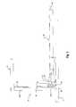
- FIG. 1illustrates an exercise device according to one embodiment of the present invention.
- FIG. 2illustrates a partial perspective view of the exercise device of FIG. 1 showing an incline mechanism.
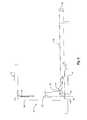
- FIG. 3illustrates a side elevation view of the exercise device of FIG. 1 with the exercise device in a neutral position.
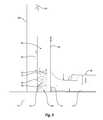
- FIG. 4illustrates a side elevation view of the exercise device of FIG. 1 with the exercise device in a declined position.
- FIG. 5illustrates a side elevation view of the exercise device of FIG. 1 with the exercise device in an inclined position.
- FIG. 6illustrates a partial side elevation view of the incline mechanism of FIG. 2 .
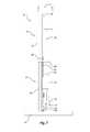
- FIG. 7illustrates a side elevation view of the exercise device of FIG. 1 with a portion of the exercise device folded into a storage position.
- FIG. 8illustrates an end perspective view of the exercise device of FIG. 1 and a latching mechanism in an unlatched state.
- FIG. 9illustrates a rear perspective view of the exercise device of FIG. 1 with the treadbase in a storage position and the latching mechanism in an unlatched state.
- FIG. 10illustrates an end perspective view of the exercise device of FIG. 1 with the latching mechanism in a latched state.
- FIG. 11illustrates an exercise device according to another embodiment of the present invention, with a partial cutaway to reveal an incline mechanism.
- FIG. 1Depicted in FIG. 1 is a representation of an exercise device 10 according to one embodiment of the present invention.
- Exercise device 10which is illustrated as a treadmill, includes a frame 12 having a base 14 and a generally upright support structure 16 .
- handle bar assembly 18Connected to the upper end of support structure 16 is an optional handle bar assembly 18 .
- handle bar assembly 18includes generally parallel handle bars 20 , 22 and cross bar 24 connected between handle bars 20 , 22 .
- Cross bar 24may optionally be designed and used as a handle bar.
- cross bar 24is horizontally offset from support structure 16 .
- An optional console with a display and/or one or more inputsmay optionally be mounted on support structure 16 and/or handle bar assembly 18 .
- a treadbase 26is connected to support structure 16 and typically includes front and rear pulleys 28 , 30 with a continuous belt 32 extending between and around front and rear pulleys 28 , 30 , respectively.
- Front and rear pulleys 28 , 30 and continuous belt 32may each be considered a movable element that is movable during the performance of an exercise.
- a deck 34commonly fabricated from wood, metal or a composite material such as fiber glass, typically supports the upper run of belt 32 and an exercising individual positioned upon belt 32 .
- front pulley 28 and rear pulley 30may be mechanically connected to an electric drive motor 36 by way of a drive belt 38 .
- drive motor 36is connected to front pulley 28 via drive belt 38 in order to turn front pulley 28 and, in turn, rotate belt 32 .
- Motor 36is optionally electrically connected to a controller 40 that controls the operation of motor 36 , and thus the speed of belt 32 , in response to various user inputs or other control signals.
- exercise device 10In addition to the ability to control and vary the speed of belt 32 , exercise device 10 also permits the degree of incline or decline of treadbase 26 , and thus belt 32 , to be varied relative to base 14 , or the floor or other support surface upon which exercise device 10 rests.
- treadbase 26may be movably connected to support structure 16 . As shown in FIG. 1 , for example, a first end 42 of treadbase 26 is movably connected to support structure 16 to allow the height of first end 42 to change relative to base 14 , a support surface, or a second end 44 of treadbase 26 . As is understood, changing the height of first end 42 increases or decreases the incline of treadbase 26 .
- exercise device 10includes an incline mechanism 50 that adjusts the incline of treadbase 26 by adjusting the height of first end 42 of treadbase 26 .
- the incline mechanism 50may optionally be vertically aligned with and attached to the upright support structure 16 .
- incline mechanism 50includes a rod 52 , pinions 54 , racks 56 , and an incline motor 58 .
- Rod 52has a pinion 54 fixedly connected on at least one end, and preferably both ends thereof.
- Each pinion 54engages a rack 56 , or linear gear bar, on support structure 16 .
- a rack 56is connected to each of the two generally vertical members 16 A, 16 B of support structure 16 .
- Pinions 54 and racks 56have teeth that engage one another.
- Incline motor 58is mounted on first end 42 of treadbase 26 and rotates rod 52 , which causes pinions 54 to likewise rotate. The engagement between the teeth of pinions 54 and racks 56 and the rotation of pinions 54 causes pinions 54 to move up and down racks 56 .
- First end 42 of treadbase 26is rotatably mounted on rod 52 such that rod 52 is able to rotate relative to treadbase 26 and, as will be discussed below, such that treadbase 26 is able to rotate about and relative to rod 52 .
- pinions 54move up and down racks 56 , the height of first end 42 , and thus the incline of treadbase 26 , is adjusted between a variety of positions.
- pinions 54may be moved to an intermediate position that orients treadbase 26 in a neutral position as shown in FIG. 3 . When in the neutral position, treadbase 26 may be generally parallel to base 14 and/or a support surface upon which exercise device 10 rests.
- pinions 54may move up or down racks 56 to an intermediate position that causes treadbase 26 to pivot, rotate, or be otherwise reoriented so that first and second ends 42 , 44 are generally level with one another.
- treadbase 26When treadbase 26 is in the neutral position, treadbase 26 may replicate a generally flat, level surface for a user ambulating on exercise device 10 .
- treadbase 26When pinions 54 rotate down racks 56 to the vertically lowest ends of racks 56 , treadbase 26 may be in a fully declined position as shown in FIG. 4 . In the fully declined position, first end 42 of treadbase 26 may be positioned vertically lower than second end 44 of treadbase 26 . A declined position of treadbase 26 replicates for a user the experience of ambulating down a hill.
- treadbase 26may be moved to a fully inclined position by rotating pinions 54 up to the vertically highest ends of racks 56 .
- first end 42 of treadbase 26may be positioned vertically higher than second end 44 of treadbase 26 .
- An inclined position of treadbase 26replicates for a user the experience of ambulating up a hill.
- incline mechanism 50may also move treadbase 26 to substantially any position between the fully declined and fully inclined positions.
- Incline mechanism 50may also allow for treadbase 26 to be readily inclined or reoriented to certain positions, such as the fully declined, fully inclined, and neutral positions.
- one or more magnets 60may be positioned on or in pinion 54 and one or more sensors 62 may be positioned on or adjacent rack 56 .
- the one or more sensors 62may be capable of detecting the magnetic field surrounding magnets 60 when magnets 60 are in close proximity to the sensors 62 .
- a sensor 62 Amay be positioned on rack 56 so that magnet 60 is in close proximity to sensor 62 A when treadbase 26 is in the neutral position.
- Sensor 62 Amay be in communication with incline motor 58 and/or controller 40 .
- sensor 62 Amay send a signal to incline motor 58 and/or controller 40 .
- incline motor 58 and/or controller 40may stop the movement of pinions 54 so that treadbase 26 stops in the neutral position.
- incline motor 58may rotate pinions 54 up or down racks 56 until magnet 60 is in close proximity to sensor 62 A, at which point the rotation of pinions 54 will be stopped and treadbase 26 will be in the neutral position.
- FIG. 4illustrates a sensor 62 B positioned near the lower end of rack 56 .
- Sensor 62 Bmay detect the presence of magnet 60 and communicate with incline motor 58 and/or controller 40 to stop the movement of pinions 54 so as to position treadbase 26 in the fully declined position shown in FIG. 4 .
- a sensor 62 Cmay be positioned near the top of rack 56 to facilitate the positioning of treadbase 26 in the fully inclined position, as shown in FIG. 5 .
- racks 56may include fewer or more than three sensors 62 to facilitate the ready positioning of treadbase 26 in any number of inclined or declined positions. It is also understood that other types of position switches may be employed, including mechanical switches, electrical switches, electromechanical switches, and the like.
- a guide 64 and a bracket assembly 66will be described. While a guide 64 and a bracket assembly 66 may be, but are not necessarily, included on both sides of exercise device 10 , the following discussion will focus on a guide and bracket assembly on one side of exercise device 10 , with the understanding that a guide and bracket assembly on the other side, if any, may be similar or identical.
- guide 64is a generally rectangular frame connected to the rear side of vertical member 16 A.
- Guide 64includes a generally rectangular opening 68 therethrough.
- Guide 64directs the movement of bracket assembly 66 and cooperates with bracket assembly 66 to maintain full engagement between pinion 54 and rack 56 .
- Bracket assembly 66includes a first bracket 70 mounted on rod 52 such that rod 52 may rotate relative to first bracket 70 .
- First bracket 70has first and second wheels 72 , 74 rotatably mounted on opposing ends thereof and which roll against the inner surface of opening 68 in guide 64 .
- Bracket assembly 66also includes a second bracket 76 fixedly connected to first bracket 70 .
- a first end of second bracket 76is mounted on rod 52 such that rod 52 may rotate relative to second bracket 76 , while a second end of second bracket 76 extends away from rod 52 .
- a gas spring 78is connected between the second end of second bracket 76 and treadbase 26 as shown in FIG. 2 .
- Gas spring 78applies a continuous force between the second end of bracket 76 and the connection point between gas spring 78 and treadbase 26 .
- the force from gas spring 78continuously tries to rotate bracket assembly 66 clockwise (when viewed from the perspective shown in FIG. 6 ) about rod 52 .
- Various benefitsare achieved as a result of the force applied to bracket assembly 66 by gas spring 78 . For instance, first and second wheels 72 , 74 are continuously pushed into engagement with the opposing inner surfaces of opening 68 in guide 64 , as shown throughout the Figures.
- bracket assembly 66 and gas spring 78cooperate to restrict the movement of rod 52 (or a center point thereof) to within a single plane that is substantially parallel to racks 56 .
- racks 56are substantially vertical, thus rod 52 is able to move vertically, but not horizontally.
- pinions 54are mounted on the opposing ends of rod 52 .
- restricting the movement of rod 52 (or a center point thereof) to within a single plane that is substantially parallel to racks 56likewise restricts the movement of pinions 54 (or a center point thereof) to within a plane that is substantially parallel to racks 56 .
- pinions 54are able to move vertically, but not horizontally. As a result, pinions 54 remain fully engaged with racks 56 regardless of the vertical position or vertical movements of pinions 54 .
- first end 42 of treadbase 26is rotatably mounted on rod 52 .
- Rotatably mounting first end 42 on rod 52enables treadbase 26 to be reoriented or folded from an operating position as shown in FIGS. 1-6 to a storage position as shown in FIG. 7 .
- treadbase 26When treadbase 26 is in the operating position a user is able to ambulate thereon.
- treadbase 26may be reoriented to the storage position when exercise device 10 is not in use, thereby reducing the footprint of exercise device 10 .
- treadbase 26is in a substantially vertical orientation when in the storage position. That is, second end 44 of treadbase 26 is positioned substantially directly above first end 42 .
- belt drive motor 36 and incline motor 58also rotate about rod 52 when treadbase 26 is reoriented between the operating and storage positions.
- belt drive motor 36 and incline motor 58are mounted on treadbase 26 between rod 52 and belt 32 .
- belt drive motor 36 and incline motor 58are positioned generally above rod 52 and below belt 32 when treadbase 26 is in the storage position.
- both the incline and reorientation capabilitiesare made possible, at least in part, by mounting treadbase 26 on rod 52 . More specifically, because first end 42 of treadbase 26 is mounted on rod 52 , adjusting the height of rod 52 results in an incline change for treadbase 26 . Also, having first end 42 pivotally mounted on rod 52 enables treadbase to be reoriented about rod 52 between the storage and operating positions.
- rod 52can move vertically up and down within a single plane and with minimal or no horizontal movement.
- treadbase 26can be rotated about rod 52 regardless of the height of rod 52 .
- treadbase 26may rotate between operating and storage positions about a pivot point (e.g., rod 52 ) that can move vertically and with little or no horizontal movement.
- handle bar assembly 18is shown in the operating position in FIGS. 1 and 3 - 5 .
- handle bars 20 , 22extend rearwardly from vertical members 16 A, 16 B in a generally horizontal direction such that vertical members 16 A, 16 B and handle bars 20 , 22 are generally transverse.
- handle bars 20 , 22extend upwardly from vertical members 16 A, 16 B in a generally vertical direction such that vertical members 16 A, 16 B and handle bars 20 , 22 are generally parallel or collinear.
- handle bar assembly 18is pivotally connected to support structure 16 at pivots 80 .
- Pivots 80allow handle bar assembly 18 to rotate or pivot thereabout, such as between the operating and storage positions.
- treadbase 26When treadbase 26 is reoriented from the operating position to the storage position, treadbase 26 engages handle bar assembly 18 in a manner that causes handle bar assembly 18 to be reoriented from the operating position to the storage position. More specifically, as treadbase 26 is reoriented toward the storage position, the top surface of treadbase 26 engages cross bar 24 of handle bar assembly 18 . As treadbase 26 continues to rotate toward the storage position, the force applied to cross bar 24 by treadbase 26 causes handle bar assembly 18 to rotate about pivots 80 toward the storage position. When treadbase 26 has been completely rotated to the storage position, handle bar assembly 18 will also be in its storage position.
- exercise device 10has a slim and compact storage profile width, which is indicated at reference P.
- the storage profile width P of exercise device 10may be about six (6) inches or about eight (8) inches. In other embodiments, the storage profile width P of exercise device 10 may be between about four (4) inches and about twelve (12) inches.
- the storage profile width P of the illustrated embodimentdoes not include the width or base 14 . In other embodiment, however, base 14 may be sized to fit within the compact storage profile width P.
- Cushionssuch as rubber or foam stops, may optionally be provided on cross bar 24 or treadbase 26 to cushion the engagement and prevent damage therebetween.
- cross bar 24is provided with two cushions 82 .
- Cushions 82are space apart and are positioned on cross bar 24 so as to be engaged by treadbase 26 when treadbase 26 is reoriented toward the storage position.
- Cushions 82may be formed of force absorbing, non-abrasive, and/or resilient materials that prevent damage to cross bar 24 or treadbase 26 when treadbase 26 engages cross bar 24 .
- handle bar assembly 18When treadbase 26 is reoriented from the storage position to the operating position, handle bar assembly 18 may also be reoriented to its operating position. That is, handle bar assembly 18 may pivot about pivots 80 from the storage position shown in FIG. 7 to the operating position shown in FIG. 1 .
- a biasing membermay facilitate the reorientation of handle bar assembly 18 from the storage position to the operating position.
- a biasing member 84which is illustrated as a spring, is connected between vertical member 16 A and handle bar 20 . Biasing member 84 may exert a force on handle bar 20 that biases handle bar assembly 18 toward the operating position. Accordingly, when treadbase 26 is reoriented toward the operating position, biasing member 84 acts on handle bar assembly 18 to likewise reorient handle bar assembly 18 toward its operating position.
- Support structure 16 and/or handle bar assembly 18may include one or more stops or other features that prevent handle bar assembly 18 from rotating beyond the operating or storage positions.
- vertical members 16 A, 16 Bhave stops 86 , 88 , respectively, that prevent handle bar assembly 18 from rotating beyond the operating position.
- stops 86 , 88extend rearwardly from vertical members 16 A, 16 B so that handle bars 20 , 22 will engage stops 86 , 88 when handle bar assembly 18 has rotated from the storage position to the operating position, thereby preventing handle bar assembly from rotating beyond the operating position.
- Biasing member 84may likewise act as a stop to prevent handle bar assembly 18 from rotating beyond the storage position.
- one or more stops similar to stops 86 , 88may be provided on vertical members 16 A, 16 B or handle bar assembly 18 to prevent handle bar assembly 18 from rotating beyond the storage position.
- gas spring 78is connected between bracket assembly 66 and treadbase 26 .
- gas spring 78may also assist with the reorientation of treadbase 26 .
- gas spring 78may exert a force on treadbase 26 that assists the user in lifting second end 44 .
- the force exerted by gas spring 78may reduce the amount of lifting force that the user has to exert in order to lift treadbase 26 into the storage position.
- the force exerted by gas spring 78 on treadbase 26may provide for a more controlled descent of treadbase 26 .
- FIGS. 8-10illustrate a latching mechanism 90 according to one embodiment of the invention.
- Latching mechanism 90selectively maintains treadbase 26 in the storage position.
- latching mechanism 90includes a latch pin 92 and a latch plate 94 .
- Latch pin 92is able to selectively engage or disengage latch plate 94 to selectively maintain treadbase 26 in the storage position or to allow treadbase 26 to be reoriented to the operating position.
- Latch pin 92is connected to first end 42 of treadbase 26 via brackets 98 , 100 . As shown, latch pin 92 has a longitudinal axis that is substantially perpendicular to a longitudinal axis of treadbase 26 and that is generally parallel to rod 52 . Because latch pin 92 is connected to treadbase 26 , latch pin 92 rotates about rod 52 when treadbase 26 is reoriented between the operating and storage positions.
- Latch plate 94is mounted on a cross bar 102 that extends between vertical members 16 A, 16 B.
- a channel 96is formed in latch plate 94 .
- channel 96has a forwardly bent shape. In other embodiments, however, channel 96 may have a rearwardly bent shape or channel 96 may be straight. Regardless of its shape, channel 96 may be designed to selectively receive and retain latch pin 92 therein when treadbase 26 is in the storage position. For instance, channel 96 may have a generally upwardly directed opening for selectively receiving latch pin 92 therein.
- latch pin 92When latch pin 92 is positioned in channel 96 , the movement of treadbase 26 is restricted to prevent treadbase 26 from inadvertently moving from the storage position to the operating position. Nevertheless, latch pin 92 may be selectively removed from channel 96 to allow treadbase 26 to move to the operating position.
- exercise device 10is depicted with treadbase 26 in the operating position.
- latch pin 92is disengaged from latch plate 94 (e.g., not positioned within channel 96 ) when treadbase 26 is in the operating position.
- latch pin 92is disengaged from latch plate 94 (e.g., not positioned within channel 96 ) when treadbase 26 is in the operating position.
- latch plate 94e.g., not positioned within channel 96
- treadbase 26is rotated to the storage position as shown in FIG. 9 .
- latch pin 92is generally aligned with channel 96 of latch plate 94 so that latch pin 92 may be selectively moved in and out of channel 96 .
- the alignment between latch pin 92 and channel 96may be in a generally vertical direction, a generally horizontal direction, or an angled direction (e.g., relative to a support surface).
- treadbase 26is rotated so that second end 44 of treadbase 26 is positioned generally above first end 42 and latch pin 92 is vertically aligned with the generally upwardly directed opening of channel 96 .
- latching mechanism 90has not been engaged to maintain treadbase 26 in the storage position.
- latch pin 92is aligned with, but has not been positioned within, channel 96 of latch plate 94 . Rather, in the embodiment illustrated in FIG. 9 , latch pin 92 is positioned vertically above the opening to channel 96 .
- latch pin 92is positioned in channel 96 as shown in FIG. 10 .
- the positioning of latch pin 92 in channel 96may be accomplished by activating incline motor 58 .
- activation of incline motor 58changes the vertical position of treadbase 26 and latch pin 92 .
- incline motor 58may be activated to move treadbase 26 in a generally vertical direction to lower treadbase 26 .
- latch pin 92enters and is positioned in channel 96 as shown in FIG. 10 .
- the usermay lift second end 44 until treadbase 26 is in the storage position, at which point incline motor 58 may be activated to lower treadbase 26 and thereby position latch pin 92 in channel 96 .
- incline motor 58may be activated to move treadbase 26 in a generally vertical direction to raise treadbase 26 and thereby withdraw latch pin 92 from channel 96 .
- treadbase 26With latch pin 92 removed from channel 96 , treadbase 26 may be rotated from the storage position to the operating position.
- latching mechanism 90may be arranged such that treadbase 26 may be moved in a generally horizontal direction or in an angled direction (e.g., relative to a support surface) in order to position latch pin 92 in or remove latch pin 92 from channel 96 .
- FIG. 11illustrates an exercise device 200 , in the form of an exercise cycle, according to another embodiment of the present invention.
- Exercise device 200in one embodiment, includes a support base 202 and a generally upright support structure 204 movably coupled thereto.
- Upright support structure 204may be referred to as a bicycle frame, although it need not look like, or act like, a bicycle frame of a road or mountain bicycle used in real-world cycling.
- Support structure 204 of the illustrated embodimentincludes a seat 206 upon which a user may sit when exercising on exercise device 200 .
- Support structure 204includes an optional handlebar assembly 208 .
- a drive assembly 210is mounted on upright support structure 204 and includes a pair of rotatable cranks 212 , each having a pedal 214 which a user can engage with his or her feet to rotate cranks 212 .
- Drive assembly 210also includes, in this embodiment, a resistance assembly 216 , which can affect the force required from the user to rotate cranks 212 .
- Resistance assembly 216includes a flywheel 218 and a resistance mechanism 220 that may vary the rotational speed of flywheel 218 , and thus the force required from the user to rotate cranks 212 .
- Exercise device 200also permits varying the vertical pitch (also referred to as incline or decline) of upright support structure 204 relative to support base 202 .
- support structure 204can be oriented in a neutral position.
- the illustrated exercise device 200may include handle bar assembly 208 and seat 206 at generally the same vertical distance from the floor or other support surface, although such is illustrative only, and the handle bar assembly 208 and seat 206 may be at different heights, even in the neutral position.
- a user sitting on seat 206may feel that he or she is sitting on a bicycle that is on a generally level surface.
- upright support structure 204can be tilted so as to be oriented in a forwardly tilted position.
- the handle bar assembly 208may be vertically closer to the floor or other support structure relative to the seat 206 , and relative to the position of handle bar assembly 208 in the neutral position. This is achieved by adjusting the vertical pitch of the upright support structure 204 relative to a floor or other support surface. Tilting upright support structure 204 forward as indicated by arrow 222 enables a user to simulate riding down a hill. Due to the sensation of descending a hill, the forwardly titled position may also be considered a declined position.
- upright support structure 204can also be oriented in a backwardly tilted position in which the handle bar assembly 208 is vertically further from the floor or other support structure when compared to seat 206 or when compared to the position of the handle bar assembly 208 in the neutral position. Tilting upright support structure 204 backwardly as indicated by arrow 224 enables a user to simulate riding up a hill. Due to the sensation of ascending up a hill, the backwardly titled position may also be considered an inclined position.
- the forward and backward tilting of upright support structure 204 to adjust the vertical pitch of the support structure 204can be accomplished through pivotally coupling upright support structure 204 to support base 202 as depicted in FIG. 11 .
- upright support structure 204is connected to support base 202 by an incline mechanism 230 .
- inclination mechanism 230includes a worm wheel 232 and a worm 234 , each of which has teeth that engage the teeth of the other.
- Worm wheel 232is fixedly mounted on or connected to upright support structure 204 . As worm 234 rotates about it longitudinal axis, worm 234 causes worm wheel 232 to rotate about it central axis.
- worm wheel 232Since worm wheel 232 is fixedly connected to support structure 204 , rotation of worm wheel 232 results in rotation of support structure 204 .
- Rotation of worm 234 in a first directioncauses worm wheel 232 and support structure 204 to rotate in the direction of arrow 222
- rotation of worm 234 in a second directioncauses worm wheel 232 and support structure 204 to rotate in the direction of arrow 224 .
- inventions of the present disclosurerelate to exercise devices that incline and/or decline to provide variety in an exercise workout.
- the exercise devicesmay be any type of exercise device, such as a treadmill, an exercise cycle, a Nordic style ski exercise device, a rower, a stepper, a hiker, a climber, an elliptical, or a striding exercise device.
- the inclining and declining capabilities of the disclosed exercise devicesallow the exercise devices to simulate real-world terrain or otherwise vary the operation of the exercise device.
- a treadmillmay have an incline mechanism that adjusts the angle of the treadbase to simulate a descent down a hill, an ascent up a hill, or traversing across level ground.
- While exercise deviceshave included inclining and declining mechanisms, typically lead-screw type extension devices, for adjusting the angle of the exercise devices, these inclining and declining mechanisms have typically been large and aesthetically unappealing.
- these mechanismshave required relatively long extension members, such as a relatively long lead screw movably positioned within a relatively long lead cylinder.
- the length of these extension membersallowed for the long lead screw to move significant distances into and out of the lead cylinder, thereby allowing for the desired range of motion for the exercise device.
- the length of these extension membersincreased the overall profile of the exercise device. For instance, in order to fit these long extension members under the treadbase of a treadmill, the treadbase would have to be elevated further off the floor. Furthermore, achieving large incline ranges proved difficult with typical extension mechanisms.
- Embodiments of the present disclosureprovide a simple and efficient mechanism for adjusting the incline or decline of an exercise device.
- the disclosed embodimentsare compact, thereby allowing for an aesthetically pleasing, low profile exercise device.
- the compact incline mechanismsare not positioned underneath the treadbase, thereby allowing the treadbase to have a lower profile.
- not having the incline mechanism underneath the treadbaseallows the exercise device to be significantly declined without interference from the incline mechanism.
- the incline mechanismallows the exercise device to be inclined significantly without having to use long, space-consuming extension members.
- the incline mechanism of the present inventionincludes a rod upon which a first end of a treadbase is rotatably mounted.
- a pinionis mounted on at least one end of the rod.
- An incline motorrotates the rod, which causes the pinion to ride up or down a rack or linear gear bar.
- the pinionmay rotate between various positions on the rack which correspond to various inclines/declines of the treadbase, including fully inclined, fully declined, and neutral positions.
- the incline mechanismenables the treadbase to be moved to substantially any grade between about a ⁇ 5% grade in the fully declined position to about a 30% grade in the fully inclined position.
- the incline mechanismmay enable the treadbase to move between grades less than ⁇ 5% and greater than 30%, or between grades that are less extreme than ⁇ 5% and 30%.
- the incline mechanismmay enable the treadbase to decline to about a ⁇ 20% grade and incline to about a 45% grade.
- the incline mechanismmay enable the incline of the treadbase to be adjusted between grades of between about ⁇ 15% to 35%, between about ⁇ 10% to 40%, between about 0% to 50%, between about ⁇ 10% to 25%, or between combinations thereof.
- the length of the racksmay be longer than illustrated in the Figures.
- the racksmay extend up any portion or the entire height of the vertical members.
- the racksmay extend from about the base to about halfway up the vertical members as shown in the Figures.
- the racksmay extend less than halfway up the vertical members if a smaller inclination range is desired.
- the racksmay extend more than halfway or substantially the entire way up the vertical members if a larger inclination range is desired.
- the racksmay extend along any portion of the vertical members, whether the lower ends of the racks are positioned adjacent the base.
- the racksmay extend from just below the handle bar assembly down a portion of the vertical members.
- the racksmay extend along a portion of the vertical members such that the upper and lower ends of the racks are spaced apart from the handle bar assembly and the base.
- the racksdo not extend up and/or are not aligned with the vertical members.
- the racksmay be spaced apart from the vertical members closer to the first or second end of the exercise device and/or closer to or further away from the center of the exercise device.
- the racksmay also be oriented at an angle relative to the vertical members.
- the lower ends of the racksmay be positioned closer to the second end of the treadbase than the upper ends of the racks. In such a case, as the pinions roll up and down the racks, the first end of the treadbase may move vertically and horizontally.
- the rack and pinion arrangementrequires little or no space underneath the treadbase.
- the treadbasemay have a very low profile and may be declined to a greater degree without increasing the height of the treadbase.
- the treadbaseis typically raised to provide room thereunder for a typical (e.g., large or long) extension device as well as room for the treadbase to pivot down.
- the rack and pinion incline mechanism disclosed hereinis not positioned underneath the treadbase, thereby allowing for the treadbase to pivot down without having to significantly increase the height of the treadbase.
- the present inventionmay also include a guide and bracket assembly to maintain full engagement between the racks and pinions of the incline mechanism.
- the bracket assemblyis continuously biased in a certain direction to maintain engagement with the guide, thereby causing the bracket assembly to travel back and forth within the guide in a straight line with minimal lateral movement.
- the pinionsare mounted adjacent the bracket assembly and move in the same direction as the bracket assembly. As a result, the movement of the pinions is limited to rolling within a straight line. This leads to the pinions being continuously maintained in full engagement with the racks.
- the bracket assemblyis omitted.
- the pinions(or a portion thereof) may be positioned within the opening in the guide.
- the openingsmay be sized to receive at least a portion of the pinions therein such that the pinions are only able to move within a single plane.
- the racksmay be formed or mounted on the inner surfaces of the openings and the toothed portions of the pinions may be positioned within the openings so as to be able to engage the racks.
- the first end of the treadbaseis rotatably mounted on the same rod upon which the pinions are mounted.
- movement of the pinions up and down the rackschanges the height of the first end of the treadbase.
- the treadbasemay be rotated about the rod to reorient the treadbase between an operating position and a storage position.
- the exercise devices of the present inventionmay also include handle bar assemblies that may be reoriented between operating and storage positions.
- the handle bar assemblymay rotate between a generally horizontal operating position and a generally vertical storage position. In the operating position, the handle bar assembly may be positioned and arranged for a user to hold during the performance of an exercise.
- the handle bar assemblymay be positioned and arranged to minimize the footprint of the exercise device when the handle bar assembly is in the storage position.
- the handle bar assemblymay be reoriented from the operating position to the storage position when the treadbase is reoriented from its operating position to its storage position. More specifically, as the treadbase is being pivoted from its operating position to its storage position, the treadbase may engage the handle bar assembly and cause the handle bar assembly to rotate from its operating position to its storage position.
- the exercise devicemay also include a biasing member that biases the handle bar assembly toward its operating position when the treadbase is not in its storage position.
- the exercise deviceWhen the treadbase and the handle bar assembly are both pivoted to their storage positions, the exercise device may have a relatively thin storage profile.
- the storage profilemay be as small as about six (6) inches or about eight (8) inches. In other embodiments, the storage profile may be between about four (4) inches and about twelve (12) inches. Accordingly, the exercise devices of the present invention may be compactly stored during shipment, storage, or periods of non-use.
- a latching mechanismmay also be included on the exercise devices of the present invention.
- the latching mechanismmay include a latch pin and latch plate having a channel formed therein for selectively receiving the latch pin.
- the latch pinmay be connected to the first end of the treadbase and may be disengaged from the latch plate when the treadbase is in the operating position.
- the latch pinWhen the treadbase is in the storage position, the latch pin may be aligned and selectively received within the channel in the latch plate.
- the latch pinOnce the treadbase is in the storage position, the latch pin may be positioned within the channel by activating the incline motor to lower the treadbase toward the latch plate. As the treadbase is lowered toward the latch plate, the latch pin is received within the channel.
- the channelmay be designed to hold the latch pin therein to prevent the treadbase from inadvertently rotating from the storage position to the operating position.
- a switch or sensormay be activated as the treadbase is reoriented from the operating position to the storage position. Activation of the switch or sensor may in turn activate the incline motor so that incline motor lowers the treadbase toward the latch plate, thereby positioning the latch pin in the channel.
- a user inputmay be provided that activates the incline motor to disengage the latch mechanism.
- the incline motoris activated to raise the treadbase, thereby withdrawing the latch pin from channel.
- a gas springmay facilitate a controlled descent of the treadbase from the storage position to the operating position.
- the gas springmay also initiate the reorientation of the treadbase from the storage position to the operating position once the latch pin is removed from the channel, thereby eliminating the need for the user to pull the second end of the treadbase down toward the support surface.
- the incline mechanism of the present inventionincludes a worm wheel fixedly mounted on an upright support structure and a worm connected to a base support. Rotation of the worm causes the worm wheel, and thus the upright support structure, to rotate in order to position the upright support structure in a forwardly titled or declined position or in a backwardly titled or inclined position.
- the worm wheelmay be rotated by the worm between various positions that correspond to various inclines/declines of the upright support structure, including fully inclined, fully declined, and neutral positions.
- the worm gear-type inclination mechanismis compact and unobtrusive. In some embodiments, this type of inclination mechanism can allow an upright support structure to tilt forward or backward as much as about 20°. For instance, the inclination mechanism may allow the upright support structure to tilt about 12° back and about 12° forward.
Landscapes
- Health & Medical Sciences (AREA)
- Cardiology (AREA)
- Vascular Medicine (AREA)
- General Health & Medical Sciences (AREA)
- Physical Education & Sports Medicine (AREA)
- Rehabilitation Tools (AREA)
Abstract
Description
Claims (20)
Priority Applications (3)
| Application Number | Priority Date | Filing Date | Title |
|---|---|---|---|
| US13/652,568US9138615B2 (en) | 2011-11-15 | 2012-10-16 | Exercise device with rack and pinion incline adjusting mechanism |
| PCT/US2012/060635WO2013074243A1 (en) | 2011-11-15 | 2012-10-17 | Exercise device with rack and pinion incline adjusting mechanism |
| EP12849303.8AEP2838623B1 (en) | 2011-11-15 | 2012-10-17 | Exercise device with rack and pinion incline adjusting mechanism |
Applications Claiming Priority (2)
| Application Number | Priority Date | Filing Date | Title |
|---|---|---|---|
| US201161559834P | 2011-11-15 | 2011-11-15 | |
| US13/652,568US9138615B2 (en) | 2011-11-15 | 2012-10-16 | Exercise device with rack and pinion incline adjusting mechanism |
Publications (2)
| Publication Number | Publication Date |
|---|---|
| US20130123073A1 US20130123073A1 (en) | 2013-05-16 |
| US9138615B2true US9138615B2 (en) | 2015-09-22 |
Family
ID=48281175
Family Applications (1)
| Application Number | Title | Priority Date | Filing Date |
|---|---|---|---|
| US13/652,568Active2033-10-12US9138615B2 (en) | 2011-11-15 | 2012-10-16 | Exercise device with rack and pinion incline adjusting mechanism |
Country Status (3)
| Country | Link |
|---|---|
| US (1) | US9138615B2 (en) |
| EP (1) | EP2838623B1 (en) |
| WO (1) | WO2013074243A1 (en) |
Cited By (68)
| Publication number | Priority date | Publication date | Assignee | Title |
|---|---|---|---|---|
| US20160074701A1 (en)* | 2014-09-12 | 2016-03-17 | Ron Wiener | Retractable treadmill desk |
| US20170136288A1 (en)* | 2015-11-18 | 2017-05-18 | Rexon Industrial Corp., Ltd. | Foldable treadmill |
| US10188890B2 (en) | 2013-12-26 | 2019-01-29 | Icon Health & Fitness, Inc. | Magnetic resistance mechanism in a cable machine |
| US10220259B2 (en) | 2012-01-05 | 2019-03-05 | Icon Health & Fitness, Inc. | System and method for controlling an exercise device |
| US10226396B2 (en) | 2014-06-20 | 2019-03-12 | Icon Health & Fitness, Inc. | Post workout massage device |
| US10252109B2 (en) | 2016-05-13 | 2019-04-09 | Icon Health & Fitness, Inc. | Weight platform treadmill |
| US10258828B2 (en) | 2015-01-16 | 2019-04-16 | Icon Health & Fitness, Inc. | Controls for an exercise device |
| US10272317B2 (en) | 2016-03-18 | 2019-04-30 | Icon Health & Fitness, Inc. | Lighted pace feature in a treadmill |
| US10279212B2 (en) | 2013-03-14 | 2019-05-07 | Icon Health & Fitness, Inc. | Strength training apparatus with flywheel and related methods |
| US10293211B2 (en) | 2016-03-18 | 2019-05-21 | Icon Health & Fitness, Inc. | Coordinated weight selection |
| US20190192898A1 (en)* | 2017-12-22 | 2019-06-27 | Icon Health & Fitness, Inc. | Inclinable Exercise Machine |
| US10335632B2 (en) | 2015-12-31 | 2019-07-02 | Nautilus, Inc. | Treadmill including a deck locking mechanism |
| US10343017B2 (en) | 2016-11-01 | 2019-07-09 | Icon Health & Fitness, Inc. | Distance sensor for console positioning |
| US10376736B2 (en) | 2016-10-12 | 2019-08-13 | Icon Health & Fitness, Inc. | Cooling an exercise device during a dive motor runway condition |
| US10391361B2 (en) | 2015-02-27 | 2019-08-27 | Icon Health & Fitness, Inc. | Simulating real-world terrain on an exercise device |
| US10398932B2 (en) | 2015-12-31 | 2019-09-03 | Nautilus, Inc. | Treadmill including a lift assistance mechanism |
| US10426989B2 (en) | 2014-06-09 | 2019-10-01 | Icon Health & Fitness, Inc. | Cable system incorporated into a treadmill |
| US10433612B2 (en) | 2014-03-10 | 2019-10-08 | Icon Health & Fitness, Inc. | Pressure sensor to quantify work |
| US10441840B2 (en) | 2016-03-18 | 2019-10-15 | Icon Health & Fitness, Inc. | Collapsible strength exercise machine |
| US10441844B2 (en) | 2016-07-01 | 2019-10-15 | Icon Health & Fitness, Inc. | Cooling systems and methods for exercise equipment |
| US10449416B2 (en) | 2015-08-26 | 2019-10-22 | Icon Health & Fitness, Inc. | Strength exercise mechanisms |
| US10471299B2 (en) | 2016-07-01 | 2019-11-12 | Icon Health & Fitness, Inc. | Systems and methods for cooling internal exercise equipment components |
| US10493349B2 (en) | 2016-03-18 | 2019-12-03 | Icon Health & Fitness, Inc. | Display on exercise device |
| US10500473B2 (en) | 2016-10-10 | 2019-12-10 | Icon Health & Fitness, Inc. | Console positioning |
| US10543395B2 (en) | 2016-12-05 | 2020-01-28 | Icon Health & Fitness, Inc. | Offsetting treadmill deck weight during operation |
| US10561894B2 (en) | 2016-03-18 | 2020-02-18 | Icon Health & Fitness, Inc. | Treadmill with removable supports |
| US10561893B2 (en) | 2016-10-12 | 2020-02-18 | Icon Health & Fitness, Inc. | Linear bearing for console positioning |
| US10625137B2 (en) | 2016-03-18 | 2020-04-21 | Icon Health & Fitness, Inc. | Coordinated displays in an exercise device |
| US10661114B2 (en) | 2016-11-01 | 2020-05-26 | Icon Health & Fitness, Inc. | Body weight lift mechanism on treadmill |
| US10671705B2 (en) | 2016-09-28 | 2020-06-02 | Icon Health & Fitness, Inc. | Customizing recipe recommendations |
| US10729965B2 (en) | 2017-12-22 | 2020-08-04 | Icon Health & Fitness, Inc. | Audible belt guide in a treadmill |
| US10786706B2 (en) | 2018-07-13 | 2020-09-29 | Icon Health & Fitness, Inc. | Cycling shoe power sensors |
| USD907722S1 (en)* | 2020-07-02 | 2021-01-12 | Shenzhen Shifeier Technology Co., Ltd. | Treadmill |
| USD908817S1 (en)* | 2020-07-01 | 2021-01-26 | Shenzhen Xunya E-Commerce Co., Ltd. | Treadmill |
| USD910123S1 (en)* | 2019-09-27 | 2021-02-09 | Zepp, Inc. | Treadmill |
| US10918905B2 (en) | 2016-10-12 | 2021-02-16 | Icon Health & Fitness, Inc. | Systems and methods for reducing runaway resistance on an exercise device |
| US10940360B2 (en) | 2015-08-26 | 2021-03-09 | Icon Health & Fitness, Inc. | Strength exercise mechanisms |
| US10953305B2 (en) | 2015-08-26 | 2021-03-23 | Icon Health & Fitness, Inc. | Strength exercise mechanisms |
| US11000730B2 (en) | 2018-03-16 | 2021-05-11 | Icon Health & Fitness, Inc. | Elliptical exercise machine |
| USD919719S1 (en)* | 2019-01-23 | 2021-05-18 | Xiamen Renhe Sports Equipment Co., Ltd. | Treadmill |
| US11033777B1 (en) | 2019-02-12 | 2021-06-15 | Icon Health & Fitness, Inc. | Stationary exercise machine |
| US11058914B2 (en) | 2016-07-01 | 2021-07-13 | Icon Health & Fitness, Inc. | Cooling methods for exercise equipment |
| USD934353S1 (en)* | 2020-07-20 | 2021-10-26 | Sailvan Times Co., Ltd. | Treadmill |
| USD934961S1 (en)* | 2020-06-10 | 2021-11-02 | Jiangxi EQI Industrial Co., Ltd | Treadmill |
| US11187285B2 (en) | 2017-12-09 | 2021-11-30 | Icon Health & Fitness, Inc. | Systems and methods for selectively rotationally fixing a pedaled drivetrain |
| US11244751B2 (en) | 2012-10-19 | 2022-02-08 | Finish Time Holdings, Llc | Method and device for providing a person with training data of an athlete as the athlete is performing a swimming workout |
| US11298577B2 (en) | 2019-02-11 | 2022-04-12 | Ifit Inc. | Cable and power rack exercise machine |
| US11326673B2 (en) | 2018-06-11 | 2022-05-10 | Ifit Inc. | Increased durability linear actuator |
| US11451108B2 (en) | 2017-08-16 | 2022-09-20 | Ifit Inc. | Systems and methods for axial impact resistance in electric motors |
| US11534654B2 (en) | 2019-01-25 | 2022-12-27 | Ifit Inc. | Systems and methods for an interactive pedaled exercise device |
| US11534651B2 (en) | 2019-08-15 | 2022-12-27 | Ifit Inc. | Adjustable dumbbell system |
| US11673036B2 (en) | 2019-11-12 | 2023-06-13 | Ifit Inc. | Exercise storage system |
| US20230191189A1 (en)* | 2021-12-16 | 2023-06-22 | Ifit Inc. | Lift mechanism for an exercise device |
| US11794070B2 (en) | 2019-05-23 | 2023-10-24 | Ifit Inc. | Systems and methods for cooling an exercise device |
| US11850497B2 (en) | 2019-10-11 | 2023-12-26 | Ifit Inc. | Modular exercise device |
| US11878199B2 (en) | 2021-02-16 | 2024-01-23 | Ifit Inc. | Safety mechanism for an adjustable dumbbell |
| US11931621B2 (en) | 2020-03-18 | 2024-03-19 | Ifit Inc. | Systems and methods for treadmill drift avoidance |
| US11951377B2 (en) | 2020-03-24 | 2024-04-09 | Ifit Inc. | Leaderboard with irregularity flags in an exercise machine system |
| US12029935B2 (en) | 2021-08-19 | 2024-07-09 | Ifit Inc. | Adjustment mechanism for an adjustable kettlebell |
| US12029961B2 (en) | 2020-03-24 | 2024-07-09 | Ifit Inc. | Flagging irregularities in user performance in an exercise machine system |
| US12176009B2 (en) | 2021-12-30 | 2024-12-24 | Ifit Inc. | Systems and methods for synchronizing workout equipment with video files |
| US12219201B2 (en) | 2021-08-05 | 2025-02-04 | Ifit Inc. | Synchronizing video workout programs across multiple devices |
| US12263371B2 (en) | 2021-04-27 | 2025-04-01 | Ifit Inc. | Devices, systems, and methods for rotating a tread belt in two directions |
| US12280294B2 (en) | 2021-10-15 | 2025-04-22 | Ifit Inc. | Magnetic clutch for a pedaled drivetrain |
| US12350573B2 (en) | 2021-04-27 | 2025-07-08 | Ifit Inc. | Systems and methods for cross-training on exercise devices |
| US12350547B2 (en) | 2022-02-28 | 2025-07-08 | Ifit Inc. | Devices, systems, and methods for moving a movable step through a transition zone |
| US12409375B2 (en) | 2022-03-18 | 2025-09-09 | Ifit Inc. | Systems and methods for haptic simulation in incline exercise devices |
| US12433815B2 (en) | 2020-10-02 | 2025-10-07 | Ifit Inc. | Massage roller with pressure sensors |
Families Citing this family (26)
| Publication number | Priority date | Publication date | Assignee | Title |
|---|---|---|---|---|
| TWM439493U (en)* | 2012-02-08 | 2012-10-21 | Superweigh Entpr Co Ltd | Treadmill as furniture |
| US20140274579A1 (en)* | 2013-03-14 | 2014-09-18 | Icon Health & Fitness, Inc. | Treadmills with adjustable decks and related methods |
| CN104606842B (en)* | 2013-11-04 | 2018-08-28 | 岱宇国际股份有限公司 | Plane type running machine |
| TWM473844U (en)* | 2013-11-06 | 2014-03-11 | Dyaco Int Inc | Flattened treadmill |
| US10207143B2 (en) | 2014-01-30 | 2019-02-19 | Icon Health & Fitness, Inc. | Low profile collapsible treadmill |
| EA033860B1 (en) | 2014-12-19 | 2019-12-02 | Тру Фитнесс Текнолоджи, Инк. | High-incline treadmill |
| TWI549719B (en)* | 2015-03-06 | 2016-09-21 | 岱宇國際股份有限公司 | Treadmill |
| US12005302B2 (en) | 2015-06-01 | 2024-06-11 | Johnson Health Tech Co., Ltd | Exercise apparatus |
| US10398933B2 (en)* | 2015-06-01 | 2019-09-03 | Johnson Health Tech Co., Ltd. | Exercise apparatus |
| US11154746B2 (en) | 2015-06-01 | 2021-10-26 | Johnson Health Tech Co., Ltd. | Exercise apparatus |
| TWM516994U (en)* | 2015-10-20 | 2016-02-11 | Ventek Fitness Corp | Lifting and folding mechanism of treadmill |
| TWI556853B (en)* | 2015-11-18 | 2016-11-11 | 力山工業股份有限公司 | Supporting apparatus for supporting a treadmill |
| US20180147440A1 (en)* | 2016-11-30 | 2018-05-31 | Bh Asia Ltd. | Treadmill |
| TWI648081B (en) | 2016-12-05 | 2019-01-21 | 美商愛康運動與健康公司 | Pull rope resistance mechanism in treadmill |
| TWI672164B (en) | 2016-12-05 | 2019-09-21 | 美商愛康運動與健康公司 | Tread belt locking mechanism |
| CN108785976B (en)* | 2018-05-21 | 2019-11-19 | 厦门凯欣达体育用品有限公司 | A kind of gradient adjustable type treadmill |
| USD918317S1 (en)* | 2018-10-01 | 2021-05-04 | Technogym S.P.A. | Exercise equipment |
| CN109603085B (en)* | 2018-12-20 | 2020-10-16 | 滨州学院 | Treadmill is used in physical training with switching-over function |
| TWM596645U (en)* | 2020-02-25 | 2020-06-11 | 亞得健康科技股份有限公司 | Treadmill with cushioning assistance |
| CN112206491B (en)* | 2020-04-29 | 2024-12-24 | 叶朝霞 | A multifunctional training platform |
| US11465031B2 (en)* | 2020-09-16 | 2022-10-11 | RevolutioNice, Inc. | Ambulation simulation systems, terrain simulation systems, treadmill systems, and related systems and methods |
| USD1057051S1 (en)* | 2021-03-25 | 2025-01-07 | Beijing Kingsmith Technology Co., Ltd | Treadmill |
| TWI761210B (en)* | 2021-05-17 | 2022-04-11 | 力山工業股份有限公司 | Treadmill with dragging prevention mechanism |
| CN114504766B (en)* | 2022-03-04 | 2022-12-16 | 中南大学湘雅医院 | A medical bedside walking machine |
| US12427368B2 (en)* | 2022-09-12 | 2025-09-30 | Michael Stephenson | Multi-function exercise apparatus with integrated treadmill, exercise platform, pull up and chin up station, push sled and resistance pulleys |
| CN219481445U (en)* | 2023-02-07 | 2023-08-08 | 深圳市阿克索健康科技有限公司 | Lifting mechanism of running machine |
Citations (25)
| Publication number | Priority date | Publication date | Assignee | Title |
|---|---|---|---|---|
| US4729558A (en) | 1985-10-11 | 1988-03-08 | Kuo Hai P | Running exerciser |
| US5352167A (en) | 1993-06-08 | 1994-10-04 | Ecm Motor Co. | Inclination drive mechanism for a treadmill |
| US5816981A (en) | 1997-05-05 | 1998-10-06 | Hung; Michael | Foldable exercise treadmill structure |
| US5833577A (en)* | 1996-09-24 | 1998-11-10 | Spirit Manufacturing, Inc. | Fold-up exercise treadmill and method |
| US5860893A (en) | 1996-01-30 | 1999-01-19 | Icon Health & Fitness | Treadmill with folding handrails |
| US5868648A (en)* | 1996-05-13 | 1999-02-09 | Ff Acquisition Corp. | Foldable treadmill apparatus and method |
| US6261209B1 (en) | 1998-05-29 | 2001-07-17 | Fitness Quest, Inc. | Folding exercise treadmill with front inclination |
| US20020016235A1 (en)* | 2000-02-02 | 2002-02-07 | Icon Health & Fitness, Inc. | System and method for selective adjustment of exercise apparatus |
| US6585624B1 (en)* | 2002-02-08 | 2003-07-01 | Alilife Industrial Co., Ltd. | Running exerciser structure |
| US20030236153A1 (en)* | 2002-06-19 | 2003-12-25 | Forhouse Corporation | Adjusting device for a tread board of a treadmill |
| US6761667B1 (en) | 2000-02-02 | 2004-07-13 | Icon Ip, Inc. | Hiking exercise apparatus |
| US20050130807A1 (en)* | 2003-12-11 | 2005-06-16 | Gordon Cutler | Incline trainer |
| US6913563B2 (en) | 2003-01-07 | 2005-07-05 | Chao-Chuan Chen | Lifting mechanism and treadmill arrangement |
| US6926644B2 (en) | 2003-10-29 | 2005-08-09 | James Chen | Folding exercise treadmill with front inclination |
| WO2006004430A2 (en) | 2004-07-06 | 2006-01-12 | Ziad Badarneh | Training apparatus |
| US7041038B2 (en) | 2004-05-12 | 2006-05-09 | Smith Jeffrey A | Folding mechanism for a treadmill |
| US20060240951A1 (en)* | 2005-04-25 | 2006-10-26 | Leao Wang | Supporting mechanism for a deck frame of a folding-up treadmill |
| US7192388B2 (en)* | 1997-10-28 | 2007-03-20 | Icon Health & Fitness, Inc. | Fold-out treadmill |
| US20070087908A1 (en)* | 2005-10-04 | 2007-04-19 | Forhouse Corporation | Treadbase lifting mechanism of a treadmill |
| US20090111666A1 (en)* | 2007-10-31 | 2009-04-30 | Leao Wang | Folding mechanism for a handrail frame assembly of a treadmill |
| US7537549B2 (en) | 2000-02-02 | 2009-05-26 | Icon Ip, Inc. | Incline assembly with cam |
| US7540828B2 (en) | 1996-01-30 | 2009-06-02 | Icon Ip, Inc. | Reorienting treadmill |
| US7736280B2 (en)* | 2004-08-17 | 2010-06-15 | Nautilus, Inc. | Treadmill deck locking mechanism |
| US7862483B2 (en) | 2000-02-02 | 2011-01-04 | Icon Ip, Inc. | Inclining treadmill with magnetic braking system |
| US20110124466A1 (en)* | 2008-07-25 | 2011-05-26 | Takashi Nishimura | Partly-inlaid treadmill |
Family Cites Families (1)
| Publication number | Priority date | Publication date | Assignee | Title |
|---|---|---|---|---|
| TW537913B (en)* | 2002-04-30 | 2003-06-21 | Forhouse Corp | Adjusting device of inclined angle for a treadmill frame |
- 2012
- 2012-10-16USUS13/652,568patent/US9138615B2/enactiveActive
- 2012-10-17EPEP12849303.8Apatent/EP2838623B1/enactiveActive
- 2012-10-17WOPCT/US2012/060635patent/WO2013074243A1/enactiveApplication Filing
Patent Citations (27)
| Publication number | Priority date | Publication date | Assignee | Title |
|---|---|---|---|---|
| US4729558A (en) | 1985-10-11 | 1988-03-08 | Kuo Hai P | Running exerciser |
| US5352167A (en) | 1993-06-08 | 1994-10-04 | Ecm Motor Co. | Inclination drive mechanism for a treadmill |
| US5860893A (en) | 1996-01-30 | 1999-01-19 | Icon Health & Fitness | Treadmill with folding handrails |
| US7540828B2 (en) | 1996-01-30 | 2009-06-02 | Icon Ip, Inc. | Reorienting treadmill |
| US5868648A (en)* | 1996-05-13 | 1999-02-09 | Ff Acquisition Corp. | Foldable treadmill apparatus and method |
| US5833577A (en)* | 1996-09-24 | 1998-11-10 | Spirit Manufacturing, Inc. | Fold-up exercise treadmill and method |
| US6110076A (en) | 1996-09-24 | 2000-08-29 | Spirit Manufacturing, Inc. | Fold-up exercise treadmill and method |
| US5816981A (en) | 1997-05-05 | 1998-10-06 | Hung; Michael | Foldable exercise treadmill structure |
| US7192388B2 (en)* | 1997-10-28 | 2007-03-20 | Icon Health & Fitness, Inc. | Fold-out treadmill |
| US6261209B1 (en) | 1998-05-29 | 2001-07-17 | Fitness Quest, Inc. | Folding exercise treadmill with front inclination |
| US20020016235A1 (en)* | 2000-02-02 | 2002-02-07 | Icon Health & Fitness, Inc. | System and method for selective adjustment of exercise apparatus |
| US6761667B1 (en) | 2000-02-02 | 2004-07-13 | Icon Ip, Inc. | Hiking exercise apparatus |
| US7537549B2 (en) | 2000-02-02 | 2009-05-26 | Icon Ip, Inc. | Incline assembly with cam |
| US7862483B2 (en) | 2000-02-02 | 2011-01-04 | Icon Ip, Inc. | Inclining treadmill with magnetic braking system |
| US6585624B1 (en)* | 2002-02-08 | 2003-07-01 | Alilife Industrial Co., Ltd. | Running exerciser structure |
| US20030236153A1 (en)* | 2002-06-19 | 2003-12-25 | Forhouse Corporation | Adjusting device for a tread board of a treadmill |
| US6913563B2 (en) | 2003-01-07 | 2005-07-05 | Chao-Chuan Chen | Lifting mechanism and treadmill arrangement |
| US6926644B2 (en) | 2003-10-29 | 2005-08-09 | James Chen | Folding exercise treadmill with front inclination |
| US20050130807A1 (en)* | 2003-12-11 | 2005-06-16 | Gordon Cutler | Incline trainer |
| US7285075B2 (en) | 2003-12-11 | 2007-10-23 | Icon Ip, Inc. | Incline trainer |
| US7041038B2 (en) | 2004-05-12 | 2006-05-09 | Smith Jeffrey A | Folding mechanism for a treadmill |
| WO2006004430A2 (en) | 2004-07-06 | 2006-01-12 | Ziad Badarneh | Training apparatus |
| US7736280B2 (en)* | 2004-08-17 | 2010-06-15 | Nautilus, Inc. | Treadmill deck locking mechanism |
| US20060240951A1 (en)* | 2005-04-25 | 2006-10-26 | Leao Wang | Supporting mechanism for a deck frame of a folding-up treadmill |
| US20070087908A1 (en)* | 2005-10-04 | 2007-04-19 | Forhouse Corporation | Treadbase lifting mechanism of a treadmill |
| US20090111666A1 (en)* | 2007-10-31 | 2009-04-30 | Leao Wang | Folding mechanism for a handrail frame assembly of a treadmill |
| US20110124466A1 (en)* | 2008-07-25 | 2011-05-26 | Takashi Nishimura | Partly-inlaid treadmill |
Non-Patent Citations (1)
| Title |
|---|
| International Search Report, PCT/US2012/060635, Oct. 17, 2012. |
Cited By (104)
| Publication number | Priority date | Publication date | Assignee | Title |
|---|---|---|---|---|
| US10220259B2 (en) | 2012-01-05 | 2019-03-05 | Icon Health & Fitness, Inc. | System and method for controlling an exercise device |
| US11810656B2 (en) | 2012-10-19 | 2023-11-07 | Finish Time Holdings, Llc | System for providing a coach with live training data of an athlete as the athlete is training |
| US11244751B2 (en) | 2012-10-19 | 2022-02-08 | Finish Time Holdings, Llc | Method and device for providing a person with training data of an athlete as the athlete is performing a swimming workout |
| US11322240B2 (en) | 2012-10-19 | 2022-05-03 | Finish Time Holdings, Llc | Method and device for providing a person with training data of an athlete as the athlete is performing a running workout |
| US11923066B2 (en) | 2012-10-19 | 2024-03-05 | Finish Time Holdings, Llc | System and method for providing a trainer with live training data of an individual as the individual is performing a training workout |
| US12340891B2 (en) | 2012-10-19 | 2025-06-24 | Finish Time Network LLC | System and method for providing a trainer with live training data of an individual as the individual is performing a training workout |
| US11338169B2 (en) | 2013-03-14 | 2022-05-24 | IFIT, Inc. | Strength training apparatus |
| US10709925B2 (en) | 2013-03-14 | 2020-07-14 | Icon Health & Fitness, Inc. | Strength training apparatus |
| US10953268B1 (en) | 2013-03-14 | 2021-03-23 | Icon Health & Fitness, Inc. | Strength training apparatus |
| US11878206B2 (en) | 2013-03-14 | 2024-01-23 | Ifit Inc. | Strength training apparatus |
| US10279212B2 (en) | 2013-03-14 | 2019-05-07 | Icon Health & Fitness, Inc. | Strength training apparatus with flywheel and related methods |
| US10967214B1 (en) | 2013-12-26 | 2021-04-06 | Icon Health & Fitness, Inc. | Cable exercise machine |
| US10188890B2 (en) | 2013-12-26 | 2019-01-29 | Icon Health & Fitness, Inc. | Magnetic resistance mechanism in a cable machine |
| US10758767B2 (en) | 2013-12-26 | 2020-09-01 | Icon Health & Fitness, Inc. | Resistance mechanism in a cable exercise machine |
| US10932517B2 (en) | 2014-03-10 | 2021-03-02 | Icon Health & Fitness, Inc. | Pressure sensor to quantify work |
| US11700905B2 (en) | 2014-03-10 | 2023-07-18 | Ifit Inc. | Pressure sensor to quantify work |
| US10433612B2 (en) | 2014-03-10 | 2019-10-08 | Icon Health & Fitness, Inc. | Pressure sensor to quantify work |
| US10426989B2 (en) | 2014-06-09 | 2019-10-01 | Icon Health & Fitness, Inc. | Cable system incorporated into a treadmill |
| US10226396B2 (en) | 2014-06-20 | 2019-03-12 | Icon Health & Fitness, Inc. | Post workout massage device |
| US20160074701A1 (en)* | 2014-09-12 | 2016-03-17 | Ron Wiener | Retractable treadmill desk |
| US9795827B2 (en)* | 2014-09-12 | 2017-10-24 | Thermogenesis Group, Inc. | Retractable treadmill desk |
| US10258828B2 (en) | 2015-01-16 | 2019-04-16 | Icon Health & Fitness, Inc. | Controls for an exercise device |
| US10391361B2 (en) | 2015-02-27 | 2019-08-27 | Icon Health & Fitness, Inc. | Simulating real-world terrain on an exercise device |
| US10449416B2 (en) | 2015-08-26 | 2019-10-22 | Icon Health & Fitness, Inc. | Strength exercise mechanisms |
| US10940360B2 (en) | 2015-08-26 | 2021-03-09 | Icon Health & Fitness, Inc. | Strength exercise mechanisms |
| US10953305B2 (en) | 2015-08-26 | 2021-03-23 | Icon Health & Fitness, Inc. | Strength exercise mechanisms |
| US10065070B2 (en)* | 2015-11-18 | 2018-09-04 | Rexon Industrial Corp., Ltd. | Foldable treadmill |
| US20170136288A1 (en)* | 2015-11-18 | 2017-05-18 | Rexon Industrial Corp., Ltd. | Foldable treadmill |
| US10398932B2 (en) | 2015-12-31 | 2019-09-03 | Nautilus, Inc. | Treadmill including a lift assistance mechanism |
| US10335632B2 (en) | 2015-12-31 | 2019-07-02 | Nautilus, Inc. | Treadmill including a deck locking mechanism |
| US10493349B2 (en) | 2016-03-18 | 2019-12-03 | Icon Health & Fitness, Inc. | Display on exercise device |
| US11013960B2 (en) | 2016-03-18 | 2021-05-25 | Icon Health & Fitness, Inc. | Exercise system including a stationary bicycle and a free weight cradle |
| US10625137B2 (en) | 2016-03-18 | 2020-04-21 | Icon Health & Fitness, Inc. | Coordinated displays in an exercise device |
| US10272317B2 (en) | 2016-03-18 | 2019-04-30 | Icon Health & Fitness, Inc. | Lighted pace feature in a treadmill |
| US10561894B2 (en) | 2016-03-18 | 2020-02-18 | Icon Health & Fitness, Inc. | Treadmill with removable supports |
| US12029943B2 (en) | 2016-03-18 | 2024-07-09 | Ifit Inc. | Stationary exercise machine configured to execute a programmed workout with aerobic portions and lifting portions |
| US10864407B2 (en) | 2016-03-18 | 2020-12-15 | Icon Health & Fitness, Inc. | Coordinated weight selection |
| US12029944B2 (en) | 2016-03-18 | 2024-07-09 | Ifit Inc. | Stationary exercise machine configured to execute a programmed workout with aerobic portions and lifting portions |
| US12023549B2 (en) | 2016-03-18 | 2024-07-02 | Ifit Inc. | Stationary exercise machine configured to execute a programmed workout with aerobic portions and lifting portions |
| US10293211B2 (en) | 2016-03-18 | 2019-05-21 | Icon Health & Fitness, Inc. | Coordinated weight selection |
| US11794075B2 (en) | 2016-03-18 | 2023-10-24 | Ifit Inc. | Stationary exercise machine configured to execute a programmed workout with aerobic portions and lifting portions |
| US11565148B2 (en) | 2016-03-18 | 2023-01-31 | Ifit Inc. | Treadmill with a scale mechanism in a motor cover |
| US10441840B2 (en) | 2016-03-18 | 2019-10-15 | Icon Health & Fitness, Inc. | Collapsible strength exercise machine |
| US10994173B2 (en) | 2016-05-13 | 2021-05-04 | Icon Health & Fitness, Inc. | Weight platform treadmill |
| US11779812B2 (en) | 2016-05-13 | 2023-10-10 | Ifit Inc. | Treadmill configured to automatically determine user exercise movement |
| US10252109B2 (en) | 2016-05-13 | 2019-04-09 | Icon Health & Fitness, Inc. | Weight platform treadmill |
| US10441844B2 (en) | 2016-07-01 | 2019-10-15 | Icon Health & Fitness, Inc. | Cooling systems and methods for exercise equipment |
| US10471299B2 (en) | 2016-07-01 | 2019-11-12 | Icon Health & Fitness, Inc. | Systems and methods for cooling internal exercise equipment components |
| US11058914B2 (en) | 2016-07-01 | 2021-07-13 | Icon Health & Fitness, Inc. | Cooling methods for exercise equipment |
| US10671705B2 (en) | 2016-09-28 | 2020-06-02 | Icon Health & Fitness, Inc. | Customizing recipe recommendations |
| US10500473B2 (en) | 2016-10-10 | 2019-12-10 | Icon Health & Fitness, Inc. | Console positioning |
| US10918905B2 (en) | 2016-10-12 | 2021-02-16 | Icon Health & Fitness, Inc. | Systems and methods for reducing runaway resistance on an exercise device |
| US10561893B2 (en) | 2016-10-12 | 2020-02-18 | Icon Health & Fitness, Inc. | Linear bearing for console positioning |
| US10376736B2 (en) | 2016-10-12 | 2019-08-13 | Icon Health & Fitness, Inc. | Cooling an exercise device during a dive motor runway condition |
| US10661114B2 (en) | 2016-11-01 | 2020-05-26 | Icon Health & Fitness, Inc. | Body weight lift mechanism on treadmill |
| US10343017B2 (en) | 2016-11-01 | 2019-07-09 | Icon Health & Fitness, Inc. | Distance sensor for console positioning |
| US10543395B2 (en) | 2016-12-05 | 2020-01-28 | Icon Health & Fitness, Inc. | Offsetting treadmill deck weight during operation |
| US11451108B2 (en) | 2017-08-16 | 2022-09-20 | Ifit Inc. | Systems and methods for axial impact resistance in electric motors |
| US12270441B2 (en) | 2017-12-09 | 2025-04-08 | Ifit Inc. | Systems and methods for selectively rotationally fixing a pedaled drivetrain |
| US11708874B2 (en) | 2017-12-09 | 2023-07-25 | Ifit Inc. | Systems and methods for selectively rotationally fixing a pedaled drivetrain |
| US11187285B2 (en) | 2017-12-09 | 2021-11-30 | Icon Health & Fitness, Inc. | Systems and methods for selectively rotationally fixing a pedaled drivetrain |
| US11680611B2 (en) | 2017-12-09 | 2023-06-20 | Ifit Inc. | Systems and methods for selectively rotationally fixing a pedaled drivetrain |
| US11058913B2 (en)* | 2017-12-22 | 2021-07-13 | Icon Health & Fitness, Inc. | Inclinable exercise machine |
| US20190192898A1 (en)* | 2017-12-22 | 2019-06-27 | Icon Health & Fitness, Inc. | Inclinable Exercise Machine |
| US10729965B2 (en) | 2017-12-22 | 2020-08-04 | Icon Health & Fitness, Inc. | Audible belt guide in a treadmill |
| US11596830B2 (en) | 2018-03-16 | 2023-03-07 | Ifit Inc. | Elliptical exercise machine |
| US11000730B2 (en) | 2018-03-16 | 2021-05-11 | Icon Health & Fitness, Inc. | Elliptical exercise machine |
| US11326673B2 (en) | 2018-06-11 | 2022-05-10 | Ifit Inc. | Increased durability linear actuator |
| US10786706B2 (en) | 2018-07-13 | 2020-09-29 | Icon Health & Fitness, Inc. | Cycling shoe power sensors |
| US12005315B2 (en) | 2018-07-13 | 2024-06-11 | Ifit Inc. | Cycling shoe power sensors |
| USD919719S1 (en)* | 2019-01-23 | 2021-05-18 | Xiamen Renhe Sports Equipment Co., Ltd. | Treadmill |
| US11534654B2 (en) | 2019-01-25 | 2022-12-27 | Ifit Inc. | Systems and methods for an interactive pedaled exercise device |
| US11642564B2 (en) | 2019-02-11 | 2023-05-09 | Ifit Inc. | Exercise machine |
| US11452903B2 (en) | 2019-02-11 | 2022-09-27 | Ifit Inc. | Exercise machine |
| US11298577B2 (en) | 2019-02-11 | 2022-04-12 | Ifit Inc. | Cable and power rack exercise machine |
| US11426633B2 (en) | 2019-02-12 | 2022-08-30 | Ifit Inc. | Controlling an exercise machine using a video workout program |
| US11058918B1 (en) | 2019-02-12 | 2021-07-13 | Icon Health & Fitness, Inc. | Producing a workout video to control a stationary exercise machine |
| US11033777B1 (en) | 2019-02-12 | 2021-06-15 | Icon Health & Fitness, Inc. | Stationary exercise machine |
| US11951358B2 (en) | 2019-02-12 | 2024-04-09 | Ifit Inc. | Encoding exercise machine control commands in subtitle streams |
| US11794070B2 (en) | 2019-05-23 | 2023-10-24 | Ifit Inc. | Systems and methods for cooling an exercise device |
| US11534651B2 (en) | 2019-08-15 | 2022-12-27 | Ifit Inc. | Adjustable dumbbell system |
| USD910123S1 (en)* | 2019-09-27 | 2021-02-09 | Zepp, Inc. | Treadmill |
| US11850497B2 (en) | 2019-10-11 | 2023-12-26 | Ifit Inc. | Modular exercise device |
| US12296247B2 (en) | 2019-10-11 | 2025-05-13 | Ifit Inc. | Modular exercise device |
| US11673036B2 (en) | 2019-11-12 | 2023-06-13 | Ifit Inc. | Exercise storage system |
| US11931621B2 (en) | 2020-03-18 | 2024-03-19 | Ifit Inc. | Systems and methods for treadmill drift avoidance |
| US12029961B2 (en) | 2020-03-24 | 2024-07-09 | Ifit Inc. | Flagging irregularities in user performance in an exercise machine system |
| US11951377B2 (en) | 2020-03-24 | 2024-04-09 | Ifit Inc. | Leaderboard with irregularity flags in an exercise machine system |
| USD934961S1 (en)* | 2020-06-10 | 2021-11-02 | Jiangxi EQI Industrial Co., Ltd | Treadmill |
| USD908817S1 (en)* | 2020-07-01 | 2021-01-26 | Shenzhen Xunya E-Commerce Co., Ltd. | Treadmill |
| USD907722S1 (en)* | 2020-07-02 | 2021-01-12 | Shenzhen Shifeier Technology Co., Ltd. | Treadmill |
| USD934353S1 (en)* | 2020-07-20 | 2021-10-26 | Sailvan Times Co., Ltd. | Treadmill |
| US12433815B2 (en) | 2020-10-02 | 2025-10-07 | Ifit Inc. | Massage roller with pressure sensors |
| US11878199B2 (en) | 2021-02-16 | 2024-01-23 | Ifit Inc. | Safety mechanism for an adjustable dumbbell |
| US12239872B2 (en) | 2021-02-16 | 2025-03-04 | Ifit Inc. | Safety mechanism for an adjustable dumbbell |
| US12263371B2 (en) | 2021-04-27 | 2025-04-01 | Ifit Inc. | Devices, systems, and methods for rotating a tread belt in two directions |
| US12350573B2 (en) | 2021-04-27 | 2025-07-08 | Ifit Inc. | Systems and methods for cross-training on exercise devices |
| US12219201B2 (en) | 2021-08-05 | 2025-02-04 | Ifit Inc. | Synchronizing video workout programs across multiple devices |
| US12029935B2 (en) | 2021-08-19 | 2024-07-09 | Ifit Inc. | Adjustment mechanism for an adjustable kettlebell |
| US12280294B2 (en) | 2021-10-15 | 2025-04-22 | Ifit Inc. | Magnetic clutch for a pedaled drivetrain |
| US20230191189A1 (en)* | 2021-12-16 | 2023-06-22 | Ifit Inc. | Lift mechanism for an exercise device |
| US12176009B2 (en) | 2021-12-30 | 2024-12-24 | Ifit Inc. | Systems and methods for synchronizing workout equipment with video files |
| US12350547B2 (en) | 2022-02-28 | 2025-07-08 | Ifit Inc. | Devices, systems, and methods for moving a movable step through a transition zone |
| US12409375B2 (en) | 2022-03-18 | 2025-09-09 | Ifit Inc. | Systems and methods for haptic simulation in incline exercise devices |
Also Published As
| Publication number | Publication date |
|---|---|
| EP2838623A1 (en) | 2015-02-25 |
| EP2838623A4 (en) | 2016-03-16 |
| WO2013074243A1 (en) | 2013-05-23 |
| EP2838623B1 (en) | 2017-06-28 |
| US20130123073A1 (en) | 2013-05-16 |
Similar Documents
| Publication | Publication Date | Title |
|---|---|---|
| US9138615B2 (en) | Exercise device with rack and pinion incline adjusting mechanism | |
| US9352185B2 (en) | Exercise device with inclination adjusting mechanism | |
| US10702736B2 (en) | Exercise cycle | |
| US9889333B2 (en) | High-incline treadmill | |
| US8556779B2 (en) | Exercise device with gliding footlink pivot guide | |
| CN106061563B (en) | Low profile collapsible treadmill | |
| TWI640340B (en) | Exercise machine with multiple exercising modes | |
| TWI576137B (en) | Ladder machine | |
| US7223209B2 (en) | Elliptical exercise apparatus | |
| US6254515B1 (en) | Apparatus for stabilizing a treadmill | |
| US20060122038A1 (en) | Folding and inclination adjustable device for treadmills | |
| FI114689B (en) | treadmill | |
| TWI589332B (en) | Adjustable lifting angle of the ladder machine | |
| EP1481710A1 (en) | Treadmill | |
| US7955231B1 (en) | Physical exercising machine | |
| US20060009335A1 (en) | Adjustable rowing machine | |
| CN2219148Y (en) | Seesaw with balance adjustment device | |
| CN117442931A (en) | Body-building equipment | |
| KR102578355B1 (en) | Skateboard having structure for converting linear reciprocating motion to rotational motion | |
| CN114788956B (en) | A multi-functional seesaw with adjustable multiple positions | |
| US6013012A (en) | Apparatus for stabilizing a treadmill | |
| TWM506622U (en) | Stepper machine with adjustable lifting angle | |
| US20110143889A1 (en) | Physical exercising machine | |
| TWM520387U (en) | Ladder | |
| KR101471102B1 (en) | Bicycle |
Legal Events
| Date | Code | Title | Description |
|---|---|---|---|
| AS | Assignment | Owner name:ICON HEALTH & FITNESS, INC., UTAH Free format text:ASSIGNMENT OF ASSIGNORS INTEREST;ASSIGNORS:OLSON, MICHAEL;DALEBOUT, WILLIAM T.;SMITH, KENT;AND OTHERS;SIGNING DATES FROM 20140513 TO 20140515;REEL/FRAME:032938/0576 | |
| AS | Assignment | Owner name:BANK OF AMERICA, N.A., AS ADMINISTRATIVE AGENT, MA Free format text:SECURITY AGREEMENT;ASSIGNORS:ICON HEALTH & FITNESS, INC.;ICON IP, INC.;REEL/FRAME:036104/0833 Effective date:20150710 | |
| STCF | Information on status: patent grant | Free format text:PATENTED CASE | |
| AS | Assignment | Owner name:ICON HEALTH & FITNESS, INC, UTAH Free format text:RELEASE OF SECURITY INTEREST IN PATENTS;ASSIGNOR:BANK OF AMERICA, N.A., ACTING IN ITS CAPACITY AS AGENT FOR THE LENDERS;REEL/FRAME:039584/0575 Effective date:20160803 Owner name:ICON IP, INC., UTAH Free format text:RELEASE OF SECURITY INTEREST IN PATENTS;ASSIGNOR:BANK OF AMERICA, N.A., ACTING IN ITS CAPACITY AS AGENT FOR THE LENDERS;REEL/FRAME:039584/0575 Effective date:20160803 Owner name:ICON DU CANADA INC., CANADA Free format text:RELEASE OF SECURITY INTEREST IN PATENTS;ASSIGNOR:BANK OF AMERICA, N.A., ACTING IN ITS CAPACITY AS AGENT FOR THE LENDERS;REEL/FRAME:039584/0575 Effective date:20160803 Owner name:FREE MOTION FITNESS, INC., UTAH Free format text:RELEASE OF SECURITY INTEREST IN PATENTS;ASSIGNOR:BANK OF AMERICA, N.A., ACTING IN ITS CAPACITY AS AGENT FOR THE LENDERS;REEL/FRAME:039584/0575 Effective date:20160803 Owner name:UNIVERSAL TECHNICAL SERVICES, UTAH Free format text:RELEASE OF SECURITY INTEREST IN PATENTS;ASSIGNOR:BANK OF AMERICA, N.A., ACTING IN ITS CAPACITY AS AGENT FOR THE LENDERS;REEL/FRAME:039584/0575 Effective date:20160803 Owner name:ICON INTERNATIONAL HOLDINGS, INC., UTAH Free format text:RELEASE OF SECURITY INTEREST IN PATENTS;ASSIGNOR:BANK OF AMERICA, N.A., ACTING IN ITS CAPACITY AS AGENT FOR THE LENDERS;REEL/FRAME:039584/0575 Effective date:20160803 Owner name:HF HOLDINGS, INC., UTAH Free format text:RELEASE OF SECURITY INTEREST IN PATENTS;ASSIGNOR:BANK OF AMERICA, N.A., ACTING IN ITS CAPACITY AS AGENT FOR THE LENDERS;REEL/FRAME:039584/0575 Effective date:20160803 Owner name:ICON - ALTRA LLC, UTAH Free format text:RELEASE OF SECURITY INTEREST IN PATENTS;ASSIGNOR:BANK OF AMERICA, N.A., ACTING IN ITS CAPACITY AS AGENT FOR THE LENDERS;REEL/FRAME:039584/0575 Effective date:20160803 | |
| AS | Assignment | Owner name:JPMORGAN CHASE BANK, N.A., AS ADMINISTRATIVE AGENT Free format text:PATENT SECURITY AGREEMENT;ASSIGNORS:ICON HEALTH FITNESS, INC.;HF HOLDINGS, INC.;UNIVERSAL TECHNICAL SERVICES;AND OTHERS;REEL/FRAME:039669/0311 Effective date:20160803 Owner name:JPMORGAN CHASE BANK, N.A., AS ADMINISTRATIVE AGENT Free format text:PATENT SECURITY AGREEMENT;ASSIGNORS:ICON HEALTH & FITNESS, INC.;HF HOLDINGS, INC.;UNIVERSAL TECHNICAL SERVICES;AND OTHERS;REEL/FRAME:039669/0311 Effective date:20160803 | |
| MAFP | Maintenance fee payment | Free format text:PAYMENT OF MAINTENANCE FEE, 4TH YEAR, LARGE ENTITY (ORIGINAL EVENT CODE: M1551); ENTITY STATUS OF PATENT OWNER: LARGE ENTITY Year of fee payment:4 | |
| AS | Assignment | Owner name:ICON IP, INC., UTAH Free format text:TERMINATION AND RELEASE OF SECURITY INTEREST IN PATENT RIGHTS;ASSIGNOR:JPMORGAN CHASE BANK, N.A., AS ADMINISTRATIVE AGENT;REEL/FRAME:052671/0737 Effective date:20200427 Owner name:ICON HEALTH & FITNESS, INC., UTAH Free format text:TERMINATION AND RELEASE OF SECURITY INTEREST IN PATENT RIGHTS;ASSIGNOR:JPMORGAN CHASE BANK, N.A., AS ADMINISTRATIVE AGENT;REEL/FRAME:052671/0737 Effective date:20200427 Owner name:JPMORGAN CHASE BANK, N.A., AS ADMINISTRATIVE AGENT, ILLINOIS Free format text:PATENT SECURITY AGREEMENT;ASSIGNOR:ICON HEALTH & FITNESS, INC.;REEL/FRAME:053548/0453 Effective date:20200427 | |
| AS | Assignment | Owner name:BANK OF AMERICA, N.A., AS ADMINISTRATIVE AGENT, CALIFORNIA Free format text:SECURITY INTEREST;ASSIGNOR:ICON HEALTH & FITNESS, INC.;REEL/FRAME:056238/0818 Effective date:20210512 | |
| AS | Assignment | Owner name:ICON HEALTH & FITNESS, INC., UTAH Free format text:TERMINATION AND RELEASE OF SECURITY INTEREST IN PATENTS;ASSIGNOR:JPMORGAN CHASE BANK, N.A., AS ADMINISTRATIVE AGENT;REEL/FRAME:056654/0951 Effective date:20210512 | |
| AS | Assignment | Owner name:IFIT INC, UTAH Free format text:CHANGE OF NAME;ASSIGNOR:ICON HEALTH & FITNESS, INC.;REEL/FRAME:058742/0476 Effective date:20210809 | |
| AS | Assignment | Owner name:IFIT INC., UTAH Free format text:TO CORRECT AN ERROR IN A COVER SHEET PREVIOUSLY RECORDED AT REEL/FRAME 058742/0476 - CORRECT ASSIGNEE NAME IFIT INC TO IFIT INC;ASSIGNOR:ICON HEALTH & FITNESS, INC.;REEL/FRAME:058957/0531 Effective date:20210809 | |
| AS | Assignment | Owner name:PLC AGENT LLC, MASSACHUSETTS Free format text:SECURITY INTEREST;ASSIGNOR:IFIT INC.;REEL/FRAME:059249/0466 Effective date:20220224 | |
| AS | Assignment | Owner name:ICON PREFERRED HOLDINGS, L.P., UTAH Free format text:INTELLECTUAL PROPERTY SECURITY AGREEMENT;ASSIGNOR:IFIT INC.;REEL/FRAME:059633/0313 Effective date:20220224 | |
| AS | Assignment | Owner name:ICON PREFERRED HOLDINGS, L.P., NEW YORK Free format text:CORRECTIVE ASSIGNMENT TO CORRECT THE THE ASSIGNEE'S ADDRESS PREVIOUSLY RECORDED AT REEL: 059633 FRAME: 0313. ASSIGNOR(S) HEREBY CONFIRMS THE ASSIGNMENT;ASSIGNOR:IFIT INC.;REEL/FRAME:060512/0315 Effective date:20220224 | |
| AS | Assignment | Owner name:LC9 CONNECTED HOLDINGS, LP, CONNECTICUT Free format text:SECURITY INTEREST;ASSIGNORS:IFIT INC.;ICON IP, INC.;REEL/FRAME:059857/0830 Effective date:20220224 | |
| MAFP | Maintenance fee payment | Free format text:PAYMENT OF MAINTENANCE FEE, 8TH YEAR, LARGE ENTITY (ORIGINAL EVENT CODE: M1552); ENTITY STATUS OF PATENT OWNER: LARGE ENTITY Year of fee payment:8 | |
| AS | Assignment | Owner name:LC9 CONNECTED HOLDINGS, LP, CONNECTICUT Free format text:SECURITY INTEREST;ASSIGNORS:IFIT INC.;ICON IP, INC.;REEL/FRAME:066094/0529 Effective date:20231214 | |
| AS | Assignment | Owner name:CERBERUS BUSINESS FINANCE AGENCY, LLC, NEW YORK Free format text:SECURITY INTEREST;ASSIGNOR:IFIT, INC.;REEL/FRAME:071278/0707 Effective date:20250512 | |
| AS | Assignment | Owner name:ICON IP INC., UTAH Free format text:RELEASE BY SECURED PARTY;ASSIGNOR:ICON PREFERRED HOLDINGS, L.P.;REEL/FRAME:071336/0725 Effective date:20250512 Owner name:IFIT INC., UTAH Free format text:RELEASE BY SECURED PARTY;ASSIGNOR:ICON PREFERRED HOLDINGS, L.P.;REEL/FRAME:071336/0725 Effective date:20250512 | |
| AS | Assignment | Owner name:ICON IP, INC., UTAH Free format text:RELEASE BY SECURED PARTY;ASSIGNOR:BANK OF AMERICA, N.A.;REEL/FRAME:071351/0624 Effective date:20250512 Owner name:IFIT, INC. (F/K/A ICON HEALTH & FITNESS, INC.), UTAH Free format text:RELEASE BY SECURED PARTY;ASSIGNOR:BANK OF AMERICA, N.A.;REEL/FRAME:071351/0624 Effective date:20250512 Owner name:ICON IP, INC., UTAH Free format text:RELEASE BY SECURED PARTY;ASSIGNOR:PLC AGENT LLC;REEL/FRAME:071358/0584 Effective date:20250512 Owner name:IFIT INC., UTAH Free format text:RELEASE BY SECURED PARTY;ASSIGNOR:PLC AGENT LLC;REEL/FRAME:071358/0584 Effective date:20250512 | |
| AS | Assignment | Owner name:ICON IP INC., UTAH Free format text:RELEASE BY SECURED PARTY;ASSIGNOR:LC9 CONNECTED HOLDINGS, LP;REEL/FRAME:071407/0001 Effective date:20250512 Owner name:IFIT INC., UTAH Free format text:RELEASE BY SECURED PARTY;ASSIGNOR:LC9 CONNECTED HOLDINGS, LP;REEL/FRAME:071407/0001 Effective date:20250512 | |
| AS | Assignment | Owner name:ICON IP INC., UTAH Free format text:RELEASE OF INTELLECTUAL PROPERTY SECURITY INTEREST (4TH LIEN);ASSIGNOR:LC9 CONNECTED HOLDINGS, LP;REEL/FRAME:071429/0479 Effective date:20250512 Owner name:IFIT INC., UTAH Free format text:RELEASE OF INTELLECTUAL PROPERTY SECURITY INTEREST (4TH LIEN);ASSIGNOR:LC9 CONNECTED HOLDINGS, LP;REEL/FRAME:071429/0479 Effective date:20250512 |