US9138343B2 - Tip protector sleeve - Google Patents
Tip protector sleeveDownload PDFInfo
- Publication number
- US9138343B2 US9138343B2US13/149,631US201113149631AUS9138343B2US 9138343 B2US9138343 B2US 9138343B2US 201113149631 AUS201113149631 AUS 201113149631AUS 9138343 B2US9138343 B2US 9138343B2
- Authority
- US
- United States
- Prior art keywords
- elongated
- tip protector
- protector sleeve
- catheter sheath
- sheath
- Prior art date
- Legal status (The legal status is an assumption and is not a legal conclusion. Google has not performed a legal analysis and makes no representation as to the accuracy of the status listed.)
- Expired - Fee Related, expires
Links
- 230000001012protectorEffects0.000titleclaimsabstractdescription104
- 238000007789sealingMethods0.000claimsdescription35
- 239000011324beadSubstances0.000claimsdescription18
- 238000000034methodMethods0.000abstractdescription14
- 230000000712assemblyEffects0.000abstractdescription3
- 238000000429assemblyMethods0.000abstractdescription3
- 239000012530fluidSubstances0.000description20
- 238000003780insertionMethods0.000description15
- 230000037431insertionEffects0.000description15
- 210000003101oviductAnatomy0.000description10
- 239000000463materialSubstances0.000description9
- 230000007246mechanismEffects0.000description8
- 206010000060Abdominal distensionDiseases0.000description5
- 230000006835compressionEffects0.000description4
- 238000007906compressionMethods0.000description4
- 229920001296polysiloxanePolymers0.000description4
- 239000000853adhesiveSubstances0.000description3
- 230000001070adhesive effectEffects0.000description3
- 238000002788crimpingMethods0.000description3
- 230000002611ovarianEffects0.000description3
- 230000037361pathwayEffects0.000description3
- 230000009467reductionEffects0.000description3
- 210000004291uterusAnatomy0.000description3
- 239000004696Poly ether ether ketoneSubstances0.000description2
- 229920002614Polyether block amidePolymers0.000description2
- FAPWRFPIFSIZLT-UHFFFAOYSA-MSodium chlorideChemical compound[Na+].[Cl-]FAPWRFPIFSIZLT-UHFFFAOYSA-M0.000description2
- 210000004996female reproductive systemAnatomy0.000description2
- 230000003287optical effectEffects0.000description2
- 229920002530polyetherether ketonePolymers0.000description2
- 239000011780sodium chlorideSubstances0.000description2
- 239000007921spraySubstances0.000description2
- 230000001954sterilising effectEffects0.000description2
- 238000004659sterilization and disinfectionMethods0.000description2
- 210000003484anatomyAnatomy0.000description1
- 238000004873anchoringMethods0.000description1
- 230000008859changeEffects0.000description1
- 239000003433contraceptive agentSubstances0.000description1
- 230000002254contraceptive effectEffects0.000description1
- 210000003811fingerAnatomy0.000description1
- 239000007943implantSubstances0.000description1
- 230000007774longtermEffects0.000description1
- 238000012986modificationMethods0.000description1
- 230000004048modificationEffects0.000description1
- 239000004417polycarbonateSubstances0.000description1
- 229920000515polycarbonatePolymers0.000description1
- 229910001220stainless steelInorganic materials0.000description1
- 239000010935stainless steelSubstances0.000description1
- 238000001356surgical procedureMethods0.000description1
- 210000003813thumbAnatomy0.000description1
- XLYOFNOQVPJJNP-UHFFFAOYSA-NwaterSubstancesOXLYOFNOQVPJJNP-UHFFFAOYSA-N0.000description1
Images


Classifications
- A—HUMAN NECESSITIES
- A61—MEDICAL OR VETERINARY SCIENCE; HYGIENE
- A61B—DIAGNOSIS; SURGERY; IDENTIFICATION
- A61B17/00—Surgical instruments, devices or methods
- A61B17/42—Gynaecological or obstetrical instruments or methods
- A—HUMAN NECESSITIES
- A61—MEDICAL OR VETERINARY SCIENCE; HYGIENE
- A61F—FILTERS IMPLANTABLE INTO BLOOD VESSELS; PROSTHESES; DEVICES PROVIDING PATENCY TO, OR PREVENTING COLLAPSING OF, TUBULAR STRUCTURES OF THE BODY, e.g. STENTS; ORTHOPAEDIC, NURSING OR CONTRACEPTIVE DEVICES; FOMENTATION; TREATMENT OR PROTECTION OF EYES OR EARS; BANDAGES, DRESSINGS OR ABSORBENT PADS; FIRST-AID KITS
- A61F6/00—Contraceptive devices; Pessaries; Applicators therefor
- A61F6/06—Contraceptive devices; Pessaries; Applicators therefor for use by females
- A61F6/14—Contraceptive devices; Pessaries; Applicators therefor for use by females intra-uterine type
- A61F6/18—Inserters or removers
- A—HUMAN NECESSITIES
- A61—MEDICAL OR VETERINARY SCIENCE; HYGIENE
- A61F—FILTERS IMPLANTABLE INTO BLOOD VESSELS; PROSTHESES; DEVICES PROVIDING PATENCY TO, OR PREVENTING COLLAPSING OF, TUBULAR STRUCTURES OF THE BODY, e.g. STENTS; ORTHOPAEDIC, NURSING OR CONTRACEPTIVE DEVICES; FOMENTATION; TREATMENT OR PROTECTION OF EYES OR EARS; BANDAGES, DRESSINGS OR ABSORBENT PADS; FIRST-AID KITS
- A61F6/00—Contraceptive devices; Pessaries; Applicators therefor
- A61F6/20—Vas deferens occluders; Fallopian occluders
- A61F6/22—Vas deferens occluders; Fallopian occluders implantable in tubes
- A61F6/225—Vas deferens occluders; Fallopian occluders implantable in tubes transcervical
- A—HUMAN NECESSITIES
- A61—MEDICAL OR VETERINARY SCIENCE; HYGIENE
- A61B—DIAGNOSIS; SURGERY; IDENTIFICATION
- A61B17/00—Surgical instruments, devices or methods
- A61B17/12—Surgical instruments, devices or methods for ligaturing or otherwise compressing tubular parts of the body, e.g. blood vessels or umbilical cord
- A61B17/12022—Occluding by internal devices, e.g. balloons or releasable wires
- A61B2017/1205—Introduction devices
- A—HUMAN NECESSITIES
- A61—MEDICAL OR VETERINARY SCIENCE; HYGIENE
- A61B—DIAGNOSIS; SURGERY; IDENTIFICATION
- A61B17/00—Surgical instruments, devices or methods
- A61B17/42—Gynaecological or obstetrical instruments or methods
- A61B2017/4233—Operations on Fallopian tubes, e.g. sterilization
- A61B2019/304—
- A—HUMAN NECESSITIES
- A61—MEDICAL OR VETERINARY SCIENCE; HYGIENE
- A61B—DIAGNOSIS; SURGERY; IDENTIFICATION
- A61B90/00—Instruments, implements or accessories specially adapted for surgery or diagnosis and not covered by any of the groups A61B1/00 - A61B50/00, e.g. for luxation treatment or for protecting wound edges
- A61B90/03—Automatic limiting or abutting means, e.g. for safety
- A61B2090/033—Abutting means, stops, e.g. abutting on tissue or skin
- A61B2090/034—Abutting means, stops, e.g. abutting on tissue or skin abutting on parts of the device itself
- F—MECHANICAL ENGINEERING; LIGHTING; HEATING; WEAPONS; BLASTING
- F04—POSITIVE - DISPLACEMENT MACHINES FOR LIQUIDS; PUMPS FOR LIQUIDS OR ELASTIC FLUIDS
- F04C—ROTARY-PISTON, OR OSCILLATING-PISTON, POSITIVE-DISPLACEMENT MACHINES FOR LIQUIDS; ROTARY-PISTON, OR OSCILLATING-PISTON, POSITIVE-DISPLACEMENT PUMPS
- F04C2270/00—Control; Monitoring or safety arrangements
- F04C2270/04—Force
- F04C2270/041—Controlled or regulated
- Y—GENERAL TAGGING OF NEW TECHNOLOGICAL DEVELOPMENTS; GENERAL TAGGING OF CROSS-SECTIONAL TECHNOLOGIES SPANNING OVER SEVERAL SECTIONS OF THE IPC; TECHNICAL SUBJECTS COVERED BY FORMER USPC CROSS-REFERENCE ART COLLECTIONS [XRACs] AND DIGESTS
- Y10—TECHNICAL SUBJECTS COVERED BY FORMER USPC
- Y10T—TECHNICAL SUBJECTS COVERED BY FORMER US CLASSIFICATION
- Y10T29/00—Metal working
- Y10T29/49—Method of mechanical manufacture
- Y10T29/49826—Assembling or joining
- Y10T29/49828—Progressively advancing of work assembly station or assembled portion of work
- Y—GENERAL TAGGING OF NEW TECHNOLOGICAL DEVELOPMENTS; GENERAL TAGGING OF CROSS-SECTIONAL TECHNOLOGIES SPANNING OVER SEVERAL SECTIONS OF THE IPC; TECHNICAL SUBJECTS COVERED BY FORMER USPC CROSS-REFERENCE ART COLLECTIONS [XRACs] AND DIGESTS
- Y10—TECHNICAL SUBJECTS COVERED BY FORMER USPC
- Y10T—TECHNICAL SUBJECTS COVERED BY FORMER US CLASSIFICATION
- Y10T29/00—Metal working
- Y10T29/49—Method of mechanical manufacture
- Y10T29/49826—Assembling or joining
- Y10T29/49908—Joining by deforming
- Y10T29/49915—Overedge assembling of seated part
- Y10T29/49917—Overedge assembling of seated part by necking in cup or tube wall
Definitions
- Embodiments of the present inventionrelate to the field minimally invasive surgical medical devices and medical procedures. More specifically, embodiments of the present invention relate to devices and methods used for transcervical gynecological procedures.
- Female contraception and sterilizationmay be affected by transervically introducing an object into a fallopian tube to inhibit conception.
- Devices, systems and methods for such a contraceptive approachhave been described in various patents and patent applications assigned to the present assignee.
- U.S. Pat. Nos. 6,526,979, 6,634,361U.S. patent application Ser. No. 11/165,733 published as U.S. Publication No. 2006/0293560 and U.S. patent application Ser. No. 12/605,304 describe transcervically inserting an insert (also referred to as implant and device) into an ostium of a fallopian tube and mechanically anchoring the insert within the fallopian tube.
- an insertalso referred to as implant and device
- Tissue in-growth into the “Essure”® insertprovides long-term contraception and/or permanent sterilization without the need for surgical procedures.
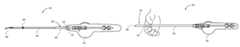
- the insertmay be delivered to the fallopian tube with a delivery catheter assembly such as the one illustrated in FIG. 1 .
- the delivery catheter assembly 100is formed of a control device 102 such as a handle, an elongated sheath 104 , and an insert 106 .
- the delivery catheter assembly 100may be transcervically positioned into the uterus and the fallopian tubes via a hysteroscope system.
- the hysteroscope system 200may include a working channel 202 into which the delivery catheter assembly is inserted. Advancement of the delivery catheter system within the uterus and the fallopian tubes is usually facilitated by distending the uterus with a distention fluid, such as saline, and viewing the placement with the hysteroscope system.
- a valve clamp 208such as a ball valve clamp, and an access port 206 are positioned at the tip of the working channel 202 . Closing the valve clamp 208 may seal the entrance of the working channel 202 to prevent a distention fluid from leaking out of the access port 206 .
- a sealing cap 230 including a pierceable end 232can be placed over the access port 206 to prevent distention fluid from leaking out of the hysteroscope system when a delivery catheter assembly occupies the working channel of the hysteroscope system.
- An introducer 220may be used in order to prevent damaging the tip the elongated sheath 104 or insert 106 of the delivery catheter assembly 100 during insertion through the pierceable end 232 of the sealing cap 230 and access port 206 , and into the working channel 202 of the hysteroscope system 200 .
- Introducer 220includes a sheath portion 222 and slit opening 224 to aid in grasping and in the removal of the introducer 220 .
- the introducer 220is inserted through the pierceable end 232 of the sealing cap 230 and into the working channel 202 prior to inserting the delivery catheter assembly 100 .
- fluidcan spray out of the introducer 220 and onto the physician or physician's assistant. The amount of fluid spray-back can be significant depending on the distention fluid pressure during the procedure.
- the tip of delivery catheter assembly 100is inserted into the slit opening 224 and through the sheath 222 of the introducer 220 in order to advance the delivery catheter assembly 100 into the working channel 202 of the hysteroscope system. This is typically performed as soon as possible after placement of the introducer 220 into the working channel 202 in order to minimize the amount of fluid spray-back from the introducer.
- the introducer 220may then be removed or may be kept in place throughout the procedure. After insertion of the delivery catheter assembly 100 into the introducer 200 , an amount of distention fluid may still leak from between the introducer and elongated sheath 104 of the delivery catheter assembly 100 .
- Embodiments of the present inventiongenerally provide assemblies and methods of inserting a delivery catheter into a working channel of an endoscope, such as a hysteroscope system for accessing a female reproductive system. While embodiments of the invention are described with reference to a hysteroscope system, it is understood that the embodiments are not limited to such and may also be compatible with other optical surgical devices.
- embodiments of the inventiondescribe a tip protector sleeve which functions as an introducer and protects the tip of a delivery catheter assembly when piercing a sealing cap, as well as during insertion through an access port, into the working channel and past a valve clamp of a hysteroscope system.
- embodiments of the inventiondescribe a method and system which may reduce the amount of fluid spray-back and leakage associated with inserting a delivery catheter assembly into the working channel of a hysteroscope system.
- the delivery catheter assemblymay be used to deliver an insert to an ovarian pathway (e.g. a fallopian tube) of a female body.
- the delivery catheter assemblymay include a control device, an elongated catheter sheath having a distal end and a proximal end connected to the control device, and a tip protector sleeve.
- the tip protector sleevemay be locked onto the elongated catheter sheath and slideable over a length of the elongated catheter sheath between a proximal-stop position and a distal-stop position along the elongated catheter sheath.
- the delivery catheter assemblymay further include an interference stop which determines the distal-stop position and prevents the tip protector sleeve from sliding off of the distal end of the elongated catheter sheath.
- the interference stopmay include a male interference part which interferes with sliding of a female interference part over the elongated catheter sheath.
- the male interference partmay be fixed to the elongated catheter sheath, and the tip protector sleeve may comprise the female interference part.
- the tip protector sleevemay additionally incorporate a sealing valve to reduce the amount of fluid spray-back and leakage associated with inserting the delivery catheter assembly into the working channel of a hysteroscope system
- Another embodiment of the present inventionrelates to a method of forming a delivery catheter assembly which includes sliding a tip protector sleeve over a distal end of an elongated catheter sheath and toward a control device, and then fixing a bump onto a distal region of the elongated catheter sheath.
- the bumpmay be fixed onto the distal region of the elongated catheter sheath, and then the tip protector sleeve is slid over a proximal end of the elongated catheter sheath toward the bump prior to attaching the control device to the elongated catheter sheath.
- the control devicemay prevent the tip protector sleeve from sliding off a proximal end of the elongated sheath and define, in part, a proximal-stop position.
- the bumpmay prevent the tip protector sleeve from sliding off of a distal end of the elongated catheter sheath and define, in part, a distal-stop position.
- the bumpmay be fixed onto a distal region of the elongated catheter sheath by crimping a band onto the elongated catheter sheath. It is not necessary to crimp the entire length of the band, and only a proximal end of the band is crimped onto the elongated catheter shaft in an embodiment.
- Another embodiment of the present inventionrelates to a method of delivering an insert into a body lumen such as an ovarian pathway (e.g. a fallopian tube) of a female body.
- a delivery catheter assemblyin accordance with embodiments of the invention the tip protector sleeve is positioned at the distal-stop position, and the tip protector sleeve is inserted through a pierceable end of a sealing cap, through an access port of a hysteroscope system and into a working channel of the hysteroscope system.
- the distal end of the elongated catheter sheath and insertare inserted through the pierceable end of the sealing cap, through the access port and into the working channel of the hysteroscope system simultaneously with the tip protector sleeve in the distal-stop position.
- the distal end of the elongated catheter sheath and insertmay then be advanced through the tip protector sleeve and beyond the hysteroscope system to a target location within the body lumen where the insert is deployed within the body lumen.
- the tip protector sleeveis advanced through the sealing cap into the working channel until a flanged mechanical stop, such as a bead or flared portion, abuts the sealing cap (or access port if a sealing cap is not utilized) prior to advancing the elongated sheath and insert to the target location.
- a flanged mechanical stopsuch as a bead or flared portion
- FIG. 1is a cross-sectional side view illustration of a delivery catheter assembly.
- FIG. 2is an isometric view illustration of a hysteroscope system and an introducer.
- FIG. 3is an isometric view illustration of a delivery catheter assembly inserted into an introducer and working channel of a hysteroscope system.
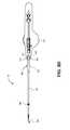
- FIG. 4is a side view illustration of a tip protector sleeve in accordance with an embodiment of the invention.
- FIG. 5Ais a side view illustration of a delivery catheter assembly with a tip protector sleeve at a proximal-stop position in accordance with an embodiment of the invention.
- FIG. 5Bis a side view illustration of a delivery catheter assembly with a flanged mechanical stop of a tip protector sleeve in a cavity of a control device in accordance with an embodiment of the invention.
- FIG. 5Cis a side view illustration of a delivery catheter assembly with a tip protector sleeve fastened into the proximal-stop position by a friction fitting in accordance with an embodiment of the invention.
- FIG. 5Dis a side view illustration of a delivery catheter assembly with a tip protector sleeve screwed into the proximal-stop position in accordance with an embodiment of the invention.
- FIG. 6is a side view illustration of a delivery catheter assembly with a tip protector sleeve at a distal-stop position in accordance with an embodiment of the invention.
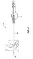
- FIG. 7is a close-up side view illustration of the proximal end of a tip protector sleeve over an elongated catheter sheath in accordance with an embodiment of the invention
- FIG. 8is a close-up cross-sectional side view illustration of the proximal end of a tip protector sleeve over an elongated catheter sheath in accordance with an embodiment of the invention
- FIG. 9is a cross-sectional side view illustration of a tip protector sleeve in accordance with an embodiment of the invention.
- FIG.10is a cross-sectional side view illustration of a tip protector sleeve in accordance with an embodiment of the invention.
- FIGS. 11A-11Care cross-sectional side view illustrations of tip protector sleeves incorporating various sealing valves in accordance with embodiments of the invention.
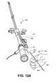
- FIGS. 12A-12Care isometric view illustrations of inserting a delivery catheter assembly into a working channel of a hysteroscope system in accordance with an embodiment of the invention.
- Embodiments of the present inventiongenerally provide assemblies and methods of inserting a delivery catheter into a working channel of an endoscope, such as a hysteroscope system or other optical surgical device for accessing a female reproductive system.
- an endoscopesuch as a hysteroscope system or other optical surgical device for accessing a female reproductive system.
- a delivery catheter assemblyincludes a control device, an elongated catheter sheath having a distal end and a proximal end connected to the control device, and a tip protector sleeve.
- the tip protector sleeve 300may include an elongated shaft 302 , a flanged mechanical stop 304 at a proximal end, and a distal end 306 .
- the distal end 306can be flat or angled to assist with piercing of a sealing cap. In an embodiment, the distal end 306 has an approximately 45 degree angled tip.
- Elongated shaft 302may be formed of a material and to a thickness which can be molded and does not buckle when piercing a sealing cap.
- elongated shaft 302may be formed of a material such as polyether ether ketone (PEEK).
- Flanged mechanical stop 304may provide variety of functions, be formed of a variety of materials and have a variety of shapes and sizes as will be explained in further detail with regard to FIGS. 5A-12C .
- flanged mechanical stop 304may be formed of a moldable material such as polycarbonate, or from the same material as the elongated shaft 302 .
- Flanged mechanical stop 304may be sized and shaped larger than the inside diameter (ID) of a corresponding access port opening to a working channel or pierceable end of a sealing cap if present in order to act as a stop mechanism that controls the insertion depth of the tip protector sleeve 300 into the working channel.
- IDinside diameter
- Flanged mechanical stop 304may also be sized and shaped to be gripped by an operator's hand to assist with sliding of the tip protector sleeve 300 over a length of the elongated catheter sheath 404 of a catheter assembly. In this respect, one function may be as a handle at the proximal end of the tip protector sleeve 300 . Flanged mechanical stop 304 may also incorporate a sealing valve to reduce the amount of fluid spray-back and leakage associated with inserting the delivery catheter assembly into a working channel.
- a delivery catheter assembly 400 in accordance with embodiments of the inventionis illustrated in which the tip protector sleeve 300 is locked onto and slideable over a length of the elongated catheter sheath 404 .
- the delivery catheter assembly 400may be formed by sliding a tip protector sleeve 300 over a distal end of an elongated catheter sheath 404 and toward a control device 402 , and then fixing a bump 408 AC onto a distal region of the elongated catheter sheath 404 .
- the bump 408may be fixed onto the distal region of the elongated catheter sheath 404 , and then the tip protector sleeve 300 is slid over a proximal end of the elongated catheter sheath 404 toward the bump 408 prior to attaching the control device 402 to the elongated catheter sheath 404 .
- the control device 402may prevent the tip protector sleeve 300 from sliding off a proximal end of the elongated sheath 404 and define, in part, a proximal-stop position.
- the bump 408may prevent the tip protector sleeve 300 from sliding off of a distal end of the elongated catheter sheath 404 and define, in part, a distal-stop position.
- An operatormay grip the flanged mechanical stop 304 by hand, for example between a thumb and index finger, and slide the tip protector sleeve over the elongated catheter sheath 404 between the proximal-stop and distal-stop positions.
- FIG. 5Ais an illustration of the tip protector sleeve 300 positioned at a proximal-stop position.
- the flanged mechanical stop 304abuts a distal end of the control device 402 , though other proximal-stop positions along the elongated catheter sheath 404 are contemplated in accordance with embodiments of the invention.
- FIGS. 5B-5Dare illustrations of embodiments in which the control device 402 is configured to allow flanged mechanical stop 304 to slide within a cavity 420 located at a distal portion of the control device 402 . Such embodiments may be useful during operation in order to utilize the full working length of the elongated catheter sheath 404 .
- the distal end of the control device 402can be advanced to abut the access port 206 of the hysteroscope system or the pierceable end 232 of a sealing cap 230 if desired during operation.
- the distal end of the control device 402can be advanced over the access port 206 of the hysteroscope system or over sealing cap 230 and the flanged mechanical stop 304 is allowed to abut the access port 206 or the pierceable end 232 of the sealing cap 230 .
- flanged mechanical stop 304may be slid into cavity 420 to abut a back wall 422 of the cavity at the proximal-stop position.
- Flanged mechanical stop 304may be also configured to fasten onto the handle 402 at the proximal-stop position.
- FIG. 5Cis an illustration of an embodiment in which flanged mechanical stop 304 may be slid into cavity 420 and fastened into the proximal-stop position by a friction fitting with sloped walls 424 of the cavity.
- FIG. 5Dis an illustration of an embodiment in which flanged mechanical stop 304 may be screwed into cavity 420 in which threads 330 on flanged mechanical stop 304 mate with threads 430 inside cavity 420 to fasten tip protection sleeve 300 in the proximal-stop position.
- a suitable fastening mechanism for fastening tip protector sleeve 300 onto control device 402is able to hold the tip protector sleeve 300 in the proximal-stop position during withdrawal of the delivery catheter assembly 400 from the working channel of the hysteroscope system.
- an operatormay slide the tip protector sleeve over the elongated catheter sheath 404 between the proximal-stop position and the distal-stop position illustrated in FIG. 6 .
- the distal end 306 of tip protector sleeve 300may extend distally beyond a distal end of the elongated catheter sheath 404 and insert 406 when at the distal-stop position.
- the tip protector sleeve 300may protect the distal ends of the elongated catheter sheath 404 and insert 406 during piercing of a sealing cap and during insertion into the working channel and past a valve clamp of the hysteroscope system.
- An interference stopmay determine the distal-stop position and prevent the tip protector sleeve 300 from sliding off of the distal end of the elongated catheter sheath 404 .
- the interference stopincludes a male interference part which interferes with sliding of a female interference part over the elongated catheter sheath.
- the male interference partmay comprise a bump 408 fixed to the elongated catheter sheath 404 .
- Bump 408may be formed along only a portion of the circumference of the elongated sheath, or may encircle the circumference of the elongated sheath.
- bump 408is a band fixed to and encircling the circumference of the elongated catheter sheath.
- bump 408is fixed to the elongated catheter sheath 404 with a sufficient shear strength to ensure that the tip protector sleeve may be removed from a working channel of a hysteroscope system along with removal of the elongated catheter sheath 404 .
- FIG. 7is a close-up side view illustration of the proximal end of a tip protector sleeve over an elongated catheter sheath in accordance with an embodiment of the invention.
- FIG. 8is a close-up cross-sectional side view illustration of the proximal end of a tip protector sleeve over an elongated catheter sheath in accordance with an embodiment of the invention.
- flanged mechanical stopmay be a bead 304 A having a barrel-like shape, though embodiments of the invention are not limited to such a shape.
- bead 304 Ais fixed to shaft 302 with an adhesive.
- bead 304 Amay be fixed to a proximal end of the elongated shaft 302 .
- Bead 304 Amay include a distal portion 308 surrounding the proximal end of the elongated shaft 302 , a shoulder portion 310 extending proximally of the elongated shaft 302 , and a backstop 312 .
- the distal portion 308may be fixed to the elongated shaft 302 with an adhesive.
- the backstop 312abuts the proximal end of the elongated shaft 302 .
- Backstop 312may also have a height which is greater than a thickness of the elongated shaft 302 .
- the heightmay be defined as the distance between and inside diameter (ID) of the backstop and an ID of the distal portion 308 of the bead 304 A.
- IDinside diameter
- the dimensions and location of the backstop 312 as they relate to the dimensions and location of bump 410create an interference stop which determines the distal-stop position and prevents the tip protector sleeve from sliding off of the distal end of the elongated catheter sheath 404 .
- the tip protector sleeve 300is locked onto an “Essure”® delivery catheter assembly.
- the ID of elongated catheter sheath 404may be between 0.0405 and 0.0420 inches and the outside diameter (OD) of elongated catheter sheath 404 may be between 0.0538 and 0.0560 inches.
- Elongated catheter sheath 404may be formed of a polyether block amide also known under the trade name PEBAX. The OD of elongated catheter sheath 404 may be used to determine the ID of bump 408 .
- bump 408may have an ID between 0.0545 and 0.0555 inches and an OD between 0.0575 and 0.0580 inches.
- the ID of bump 408may be smaller than the OD of the elongated catheter sheath 404 . In another embodiment, the OD of the elongated catheter sheath 404 is smaller than the ID of bump 408 . For example, the OD of the elongated catheter sheath 404 may be between 0.0538 and 0.0542 inches.
- Bump 408may be a band that is fixed to and encircles the elongated catheter sheath. Bump may be fixed to the elongated catheter sheath 404 by a variety of mechanisms including adhesive and crimping.
- bump 408is formed of a material which is strong enough to resist deformation during operation of the delivery catheter assembly, yet malleable enough to be suitable for crimping. For example, stainless steel possesses suitable strength and malleability.
- only a distal end 410 of the bandis crimped onto the elongated catheter sheath, as illustrated in FIG. 8 .
- bump 408is described in detail in FIG. 8 in operable relationship with bead 304 A, it is understood that bump 408 can be in operable relationship with other flanged mechanical stops, such as those illustrated in FIGS. 9-11C .
- bead 304 Amay be formed of a variety of materials and have a variety of shapes and sizes to perform a variety of functions.
- bead 304 Amay be sized and shaped larger than the inside diameter (ID) of a corresponding access port opening to a working channel or pierceable end of a sealing cap if present in order to act as a stop mechanism that controls the insertion depth of the tip protector sleeve 300 into the working channel.
- IDinside diameter
- bead 304 Amay perform the function as a handle for gripping by the operator.
- bead 304 Amay include a backstop 312 which functions as part of the female interference part.
- bead 304 Ahas an OD of approximately 0.112 inches.
- the distal portion 308 of bead 304 Amay have an ID of approximately 0.070 and may be bonded to the OD of elongated shaft 302 .
- Backstop 312may have an ID which is smaller than an OD of the proximal end of bump 408 .
- backstop 312may have an ID between 0.0565 and 0.0575 inches.
- backstop 312has a height that extends from the ID of back stop 312 to the ID of the distal portion 308 of the bead 304 , or approximately 0.013 inches.
- tip protector sleeve 300may be locked onto the delivery catheter assembly 400 .
- Shaft 302may be used to pierce a sealing cap and protect the tip of the insert 406 , elongated catheter sheath 404 or guidewire during insertion into the working channel and past a valve clamp of a hysteroscope system.
- the shaft 302 and elongated catheter sheath 404may be advanced into a working channel of a hysteroscope system without allowing a significant amount of fluid (e.g. saline) spray-back or leakage from the delivery catheter assembly.
- fluide.g. saline
- the elongated catheter sheath 404may additionally be slid through the shaft 302 to deliver the insert 406 to a body lumen, while the delivery catheter assembly 400 does not allow a significant amount of fluid leakage.
- the shaft 302may pierce the pierceable end 232 of a sealing cap 230 with the tip of the shaft 306 .
- the outside diameter of the shaft 302may fit tightly in the pierceable end 232 effectively creating a water tight seal between the sealing cap 230 and tip protector sleeve 300 .
- shaft 302may be approximately 2.82 inches long from the proximal end to the distal end of the tip 306 , which may be angled. Shaft 302 may have an ID between 0.0585 and 0.0605 inches and an OD between 0.0690 and 0.0710 inches. The shaft 302 ID may be selected to not allow for fluid to flow proximally between the shaft 302 and elongated catheter sheath 404 (and bump 408 ), while still allowing for the elongated catheter sheath 404 to slide and be advanced through the shaft 302 .
- a minimum clearance between the ID of the elongated shaft 302 (e.g. 0.059 inches) and the OD of the elongated catheter sheath 404 (e.g. 0.055 inches)provides sufficient resistance to spray-back and leakage.
- Such a minimum clearancemay be effective for overlapping constant diameters of the elongated shaft 302 and elongated catheter sheath 404 .
- tip protector sleeve 300 Bincludes an elongated shaft 302 , a bead 304 B and inner shaft 320 .
- Tip protector sleeve 300 Boperates similarly as tip protector sleeve 300 with one difference being that backstop 322 is the distal end of inner shaft 320 .
- the shape and dimensions of tip protector sleeve 300 Bare controlled so that bump 408 interferes with movement of the distal end, backstop 322 of inner shaft 320 .
- bead 304 Bmay be sized and shaped to act as a stop mechanism that controls the insertion depth of the tip protector sleeve 300 B into the working channel and may perform the function as a handle for gripping by the operator
- tip protector sleeve 300 Cincludes an elongated shaft 302 , a neck portion 332 , and a flared portion 304 C.
- Tip protector sleeve 300 Coperates similarly as tip protector sleeves 300 and 300 B.
- the neck portion 332operates as the backstop for bump 408 .
- the neck portion 332may be integrally formed with the elongated shaft 302 or be a separate member bonded to the inside diameter of elongated shaft 302
- flared portion 304 Cmay be integrally formed with the elongated shaft 302 or be a separate member bonded to the outside diameter of elongated shaft 302 .
- flared portion 304 Cmay be sized and shaped to act as a flanged mechanical stop that controls the insertion depth of the tip protector sleeve 300 C into the working channel and may perform the function as a handle for gripping by the operator.
- the tip protector sleeve 300may include a change in ID or a valve to accommodate variations in the OD of the elongated catheter sheath 404 , or to more effectively seal an elongated catheter sheath 404 with a constant OD.
- inner shaft 320is illustrated as having a smaller ID than the ID of elongated shaft 302 . In addition to functioning as an interference part, the ID of inner shaft 320 may more effectively accommodate a reduction in OD of the elongated catheter sheath 404 . Referring again to FIG.
- the ID of neck portion 332may also more effectively accommodate a reduction in OD of the elongated catheter sheath 404 in addition to functioning as an interference part.
- a minimum clearance between the ID of inner shaft 320 or ID of neck portion 332 and the OD of the elongated catheter shaft 404may provide enhanced resistance to fluid-spray back.
- FIGS. 11A-11Care illustrations embodiments of a tip protector sleeve incorporating various sealing valves to reduce the amount of fluid spray-back and leakage between the tip protector sleeve and elongated sheath of the delivery catheter assembly. While illustrated separately, it is understood that the embodiments illustrated in FIGS. 11A-11C may be combined with other embodiments of the invention. More specifically, any of the sealing valves described in reference to the illustrations in FIGS. 11A-11C may be combined with any of the embodiments further describing the proximal-stop and distal-stop positions.
- FIG. 11Ais an illustration of a tip protector sleeve 300 D including an elongated shaft 302 , a housing 304 D, and valve 340 .
- Housing 304 Dmay function as a stop mechanism that controls the insertion depth of the tip protector sleeve 300 D into the working channel and may perform the function as a handle for gripping by the operator.
- the elongated shaft 302may be coupled to a distal tip 342 of the housing 304 D which may function as a backstop for interference with a bump 408 fixed to the elongated catheter sheath 404 at the distal-stop position.
- Housing 304 Dadditionally houses valve 340 which is capable of accommodating multiple variations in OD of the elongated catheter sheath 404 .
- valve 340may be a silicone valve containing a slit at the distal end that allows for a catheter shaft to pass through it.
- the silicone materialmay allow for the slit to conform to different shapes or diameters while providing a seal. Due to the geometry on the distal end of the silicone valve, as fluid tries to pass from distal to proximal, the end of the valve may be pushed closed due to a chamfer on the end of the valve.
- FIG. 11Bis an illustration of a tip protector sleeve 300 E including an elongated shaft 302 , a housing 304 E, and a compression valve 350 including an screw cap 354 which may be threaded down onto an O-ring 352 to compress it against the elongated catheter sheath 404 .
- Housing 304 Emay function as a stop mechanism that controls the insertion depth of the tip protector sleeve 300 E into the working channel and may perform the function as a handle for gripping by the operator.
- the elongated shaft 302may be coupled to a distal tip 342 of the housing 304 E which may function as a backstop for interference with a bump fixed to the elongated catheter sheath at the distal-stop position.
- FIG. 11Cis an illustration of a tip protector sleeve 300 F including an elongated shaft 302 , a housing 304 F, and a compression valve 360 including a cap 362 , a compression spring 364 and a thin walled tube (not illustrated) inside the housing.
- the thin walled tubemay be made of a material such as silicone. Threads between the cap 362 and the housing 304 F apply a twist motion to the tube. When the tube is twisted, an inner diameter of the tube tightens like an iris. The compression spring 364 keeps the cap 362 extended and the threads hold the twist or keep the iris closed.
- housing 304 Fmay function as a stop mechanism that controls the insertion depth of the tip protector sleeve 300 F into the working channel and may perform the function as a handle for gripping by the operator.
- the elongated shaft 302may be coupled to a distal tip 342 of the housing 304 F which may function as a backstop for interference with a bump fixed to the elongated catheter sheath at the distal-stop position.
- a delivery catheter assembly in accordance with embodiments of the inventionmay be utilized to deliver an insert to an ovarian pathway (e.g. a fallopian tube) of a female body.
- the delivery catheter assemblymay protect the tip of an elongated catheter sheath, guidewire, or insert during piercing of a sealing cap and insertion into the working channel and past a valve clamp of a hysteroscope system and reduce the amount of fluid spray-back and leakage associated with inserting a delivery catheter assembly into the working channel of a hysteroscope system.
- the delivery catheter assemblyincludes a control device, an elongated catheter sheath having a distal end and a proximal end connected to the control device, and a tip protector sleeve locked onto the elongated catheter sheath and slideable over a length of the elongated catheter sheath between a proximal-stop position and a distal-stop position along the elongated catheter sheath.
- the delivery catheter assemblymay further include an insert releasably disposed within the elongated catheter sheath.
- the insertextends distally beyond the elongated catheter sheath.
- the insertincludes a preformed bend, as illustrated in FIG.
- the operatormay grasp a flanged mechanical stop 304 or other suitable portion of the tip protector sleeve 300 to position the tip protector sleeve at the distal-stop position illustrated in FIG. 6 . If a sealing valve is present on the tip protection sleeve 300 , the sealing valve may then be tightened onto the elongated catheter sheath 404 if necessary to provide an optimal seal to protect against fluid spray-back and leakage.
- the operatormay then pierce a pierceable end 232 of a sealing cap 230 with the tip protector sleeve 300 and insert the tip protector sleeve 300 through an access port 206 of a hysteroscope system 200 and into the working channel 202 of the hysteroscope system.
- the tip protector sleeve 300may be advanced past a valve clamp 208 of the hystero scope system.
- the tip protector sleeveprotects against the possibility of the exposed portion of the insert 406 from catching on the valve clamp 208 and compromising the insert integrity.
- the distal end 410 of the elongated catheter sheath 404 and insert 406are inserted through the sealing cap 230 and access port 206 , and into the working channel 202 of the hysteroscope system simultaneously with the tip protector sleeve 300 in the distal-stop position.
- the simultaneous insertion of the tip protector sleeve 300 and elongated catheter sheath 404may avoid a problem of fluid spray-back associated with sequentially inserting an introducer followed by an elongated catheter sheath.
- the tip protector sleeve 300may be advanced into the working channel simultaneously with the elongated catheter sheath and insert 406 until the flanged mechanical stop 304 abuts against the access port 206 or sealing cap 230 , if present, as illustrated in FIG. 12B .
- the distal end 410 of the elongated catheter sheath 404may then be advanced past the hysteroscope system 200 as illustrated in FIG. 12C , and onto a target location with the body lumen.
- the insert 406may then be deployed into the body lumen.
- the tip protector sleeve 300may remain inserted in the working channel 202 during the elongated catheter sheath 404 advancement and insert 406 deployment procedures or removed from the working channel 202 .
- the tip protector sleeve 300is permanently locked onto the elongated catheter sheath.
- the tip protector sleeve 300could be removed from the catheter assembly after initially advancing the catheter assembly into the working channel, for example, by including a tear joint in the tip protector sleeve in which the tip protector sleeve can be manually torn off of the elongated catheter sheath by the operator.
- the insert 406 and distal end 410 of the elongated catheter sheath 404are advanced to the target location within the body lumen while the flanged mechanical stop 304 on the tip protector sleeve 300 abuts the access port 206 or sealing cap 320 , if present.
- the amount of elongated catheter sheath 404 spanning between the flanged mechanical stop 304 and control device 402may depend upon the procedure and patient's anatomy. It is envisioned that circumstances arise where the operator may wish to insert the entire available working length of the elongated catheter sheath 404 into the patient and advance the control device 402 all the way to the access port or sealing cap, if present. In accordance with embodiments of the invention illustrated in FIGS. 5B-5D , this can be possible by including a cavity 420 in the control device 402 to accommodate the flanged mechanical stop 304 .
- the delivery catheter assemblymay be withdrawn from the working channel of the hysteroscope system.
- the bump 408 on the elongated catheter sheath 404may be withdrawn proximally against the backstop of the tip protector sleeve 300 and cause the tip protector sleeve 300 to be withdrawn from the working channel 202 of the hysteroscope system 200 .
- the flanged mechanical stop 304 on the tip protector sleeve 300can be fastened to the control device 402 . In this manner, during withdrawal of the delivery catheter assembly 400 from the working channel, the tip protector sleeve 300 remains fastened to the control device 402 .
Landscapes
- Health & Medical Sciences (AREA)
- Life Sciences & Earth Sciences (AREA)
- Reproductive Health (AREA)
- Engineering & Computer Science (AREA)
- Biomedical Technology (AREA)
- Heart & Thoracic Surgery (AREA)
- Animal Behavior & Ethology (AREA)
- General Health & Medical Sciences (AREA)
- Public Health (AREA)
- Veterinary Medicine (AREA)
- Surgery (AREA)
- Vascular Medicine (AREA)
- Pregnancy & Childbirth (AREA)
- Nuclear Medicine, Radiotherapy & Molecular Imaging (AREA)
- Gynecology & Obstetrics (AREA)
- Medical Informatics (AREA)
- Molecular Biology (AREA)
- Media Introduction/Drainage Providing Device (AREA)
- Surgical Instruments (AREA)
- Endoscopes (AREA)
- Orthopedics, Nursing, And Contraception (AREA)
- Infusion, Injection, And Reservoir Apparatuses (AREA)
Abstract
Description
Claims (11)
Priority Applications (46)
| Application Number | Priority Date | Filing Date | Title |
|---|---|---|---|
| US13/149,631US9138343B2 (en) | 2011-05-31 | 2011-05-31 | Tip protector sleeve |
| US13/323,741US20120310046A1 (en) | 2011-05-31 | 2011-12-12 | Systems for reducing fluid leakage and spray-back from endoscopic medical procedures |
| DK12728876.9TDK2713966T3 (en) | 2011-05-31 | 2012-05-30 | Muffe to peak protection |
| KR1020137034325AKR101569607B1 (en) | 2011-05-31 | 2012-05-30 | Tip protector sleeve |
| MYPI2013702301AMY158099A (en) | 2011-05-31 | 2012-05-30 | Tip protector sleeve |
| BR112013030872ABR112013030872A2 (en) | 2011-05-31 | 2012-05-30 | fluid leak reduction and splashing systems in endoscopic medical procedures. |
| HK14110023.4AHK1197169A1 (en) | 2011-05-31 | 2012-05-30 | Systems for reducing fluid leakage and spray-back from endoscopic medical procedures |
| CA2837597ACA2837597A1 (en) | 2011-05-31 | 2012-05-30 | Systems for reducing fluid leakage and spray-back from endoscopic medical procedures |
| CN201280037253.5ACN103732190B (en) | 2011-05-31 | 2012-05-30 | Protector sleeve pipe |
| NZ618487ANZ618487B2 (en) | 2011-05-31 | 2012-05-30 | Tip protector sleeve |
| MX2013014028AMX339127B (en) | 2011-05-31 | 2012-05-30 | Tip protector sleeve. |
| JP2014513665AJP2014523758A (en) | 2011-05-31 | 2012-05-30 | System for reducing fluid leakage and ejection from an endoscopic medical procedure |
| PH1/2013/502468APH12013502468A1 (en) | 2011-05-31 | 2012-05-30 | Tip protector sleeve |
| BR112013030868ABR112013030868A2 (en) | 2011-05-31 | 2012-05-30 | Protective ferrule sleeve. |
| EP12727489.2AEP2713965B1 (en) | 2011-05-31 | 2012-05-30 | Systems for reducing fluid leakage and spray-back from endoscopic medical procedures |
| AU2012262333AAU2012262333C1 (en) | 2011-05-31 | 2012-05-30 | Tip protector sleeve |
| HK14110022.5AHK1196935B (en) | 2011-05-31 | 2012-05-30 | Tip protector sleeve |
| PCT/US2012/040013WO2012166805A1 (en) | 2011-05-31 | 2012-05-30 | Tip protector sleeve |
| SG2013088893ASG195250A1 (en) | 2011-05-31 | 2012-05-30 | Tip protector sleeve |
| RU2013158810/14ARU2601179C2 (en) | 2011-05-31 | 2012-05-30 | Tip protector sleeve |
| UAA201315216AUA107060C2 (en) | 2011-05-31 | 2012-05-30 | SUBSTANCE: delivery catheter, method of its formation and method of delivery of end protective sleeve with use of hysteroscopic system |
| PE2013002740APE20141810A1 (en) | 2011-05-31 | 2012-05-30 | TIP PROTECTOR SLEEVE |
| CA2837600ACA2837600C (en) | 2011-05-31 | 2012-05-30 | Tip protector sleeve |
| RU2013158808/14ARU2573797C2 (en) | 2011-05-31 | 2012-05-30 | Systems for reducing fluid leakage and backflow accompanying endoscopic medical procedures |
| JP2014513668AJP5976792B2 (en) | 2011-05-31 | 2012-05-30 | Delivery catheter assembly |
| MX2013014025AMX2013014025A (en) | 2011-05-31 | 2012-05-30 | Systems for reducing fluid leakage and spray-back from endoscopic medical procedures. |
| PCT/US2012/040003WO2012166799A2 (en) | 2011-05-31 | 2012-05-30 | Systems for reducing fluid leakage and spray-back from endoscopic medical procedures |
| KR1020137034322AKR101546601B1 (en) | 2011-05-31 | 2012-05-30 | Systems for reducing fluid leakage and spray-back from endoscopic medical procedures |
| CN201280037129.9ACN103702641B (en) | 2011-05-31 | 2012-05-30 | Leak for the fluid reduced in endoprosthesis medical operation and return the system of spray |
| ES12728876TES2572084T3 (en) | 2011-05-31 | 2012-05-30 | Tip protective sleeve |
| AU2012262326AAU2012262326B2 (en) | 2011-05-31 | 2012-05-30 | Systems for reducing fluid leakage and spray-back from endoscopic medical procedures |
| EP12728876.9AEP2713966B1 (en) | 2011-05-31 | 2012-05-30 | Tip protector sleeve |
| SI201230549ASI2713966T1 (en) | 2011-05-31 | 2012-05-30 | Shock guard |
| IL229678AIL229678A0 (en) | 2011-05-31 | 2013-11-28 | Systems for reducing fluid leakage and spray-back from endoscopic medical procedures |
| DO2013000283ADOP2013000283A (en) | 2011-05-31 | 2013-11-28 | SPOT PROTECTOR HOSE |
| IL229679AIL229679A0 (en) | 2011-05-31 | 2013-11-28 | Tip protector sleeve |
| GT201300300AGT201300300A (en) | 2011-05-31 | 2013-11-28 | SPOT PROTECTOR HOSE |
| CU2013000162ACU20130162A7 (en) | 2011-05-31 | 2013-11-29 | SPOT PROTECTOR HOSE |
| CL2013003430ACL2013003430A1 (en) | 2011-05-31 | 2013-11-29 | Supply catheter assembly comprises: a control device, an elongated catheter sleeve having a distal end and a proximal end connected to the control device, and a protective sleeve of the tip locked on the elongated catheter sleeve and slidable on a length of the elongated catheter sleeve between a proximal stop position; process. |
| ZA2013/09112AZA201309112B (en) | 2011-05-31 | 2013-12-04 | Systems for reducing fluid leakage and spray0-back from endoscopic medical procedures |
| ZA2013/09111AZA201309111B (en) | 2011-05-31 | 2013-12-04 | Tip protector sleeve |
| CO13295350ACO6870019A2 (en) | 2011-05-31 | 2013-12-18 | Tip protective sleeve |
| CR20130674ACR20130674A (en) | 2011-05-31 | 2013-12-19 | SPOT PROTECTOR HOSE |
| ECSP13013104ECSP13013104A (en) | 2011-05-31 | 2013-12-23 | SPOT PROTECTIVE HOSE. |
| US14/839,153US20150366584A1 (en) | 2011-05-31 | 2015-08-28 | Tip protector sleeve |
| JP2016141144AJP6294401B2 (en) | 2011-05-31 | 2016-07-19 | Tip protection sleeve |
Applications Claiming Priority (1)
| Application Number | Priority Date | Filing Date | Title |
|---|---|---|---|
| US13/149,631US9138343B2 (en) | 2011-05-31 | 2011-05-31 | Tip protector sleeve |
Related Child Applications (2)
| Application Number | Title | Priority Date | Filing Date |
|---|---|---|---|
| US13/323,741Continuation-In-PartUS20120310046A1 (en) | 2011-05-31 | 2011-12-12 | Systems for reducing fluid leakage and spray-back from endoscopic medical procedures |
| US14/839,153DivisionUS20150366584A1 (en) | 2011-05-31 | 2015-08-28 | Tip protector sleeve |
Publications (2)
| Publication Number | Publication Date |
|---|---|
| US20120310215A1 US20120310215A1 (en) | 2012-12-06 |
| US9138343B2true US9138343B2 (en) | 2015-09-22 |
Family
ID=46321456
Family Applications (2)
| Application Number | Title | Priority Date | Filing Date |
|---|---|---|---|
| US13/149,631Expired - Fee RelatedUS9138343B2 (en) | 2011-05-31 | 2011-05-31 | Tip protector sleeve |
| US14/839,153AbandonedUS20150366584A1 (en) | 2011-05-31 | 2015-08-28 | Tip protector sleeve |
Family Applications After (1)
| Application Number | Title | Priority Date | Filing Date |
|---|---|---|---|
| US14/839,153AbandonedUS20150366584A1 (en) | 2011-05-31 | 2015-08-28 | Tip protector sleeve |
Country Status (28)
| Country | Link |
|---|---|
| US (2) | US9138343B2 (en) |
| EP (1) | EP2713966B1 (en) |
| JP (2) | JP5976792B2 (en) |
| KR (1) | KR101569607B1 (en) |
| CN (1) | CN103732190B (en) |
| AU (1) | AU2012262333C1 (en) |
| BR (1) | BR112013030868A2 (en) |
| CA (1) | CA2837600C (en) |
| CL (1) | CL2013003430A1 (en) |
| CO (1) | CO6870019A2 (en) |
| CR (1) | CR20130674A (en) |
| CU (1) | CU20130162A7 (en) |
| DK (1) | DK2713966T3 (en) |
| DO (1) | DOP2013000283A (en) |
| EC (1) | ECSP13013104A (en) |
| ES (1) | ES2572084T3 (en) |
| GT (1) | GT201300300A (en) |
| IL (1) | IL229679A0 (en) |
| MX (1) | MX339127B (en) |
| MY (1) | MY158099A (en) |
| PE (1) | PE20141810A1 (en) |
| PH (1) | PH12013502468A1 (en) |
| RU (1) | RU2601179C2 (en) |
| SG (1) | SG195250A1 (en) |
| SI (1) | SI2713966T1 (en) |
| UA (1) | UA107060C2 (en) |
| WO (1) | WO2012166805A1 (en) |
| ZA (1) | ZA201309111B (en) |
Cited By (4)
| Publication number | Priority date | Publication date | Assignee | Title |
|---|---|---|---|---|
| US20190142511A1 (en)* | 2016-06-09 | 2019-05-16 | Nuvaira, Inc. | Systems and methods for improved delivery of expandable catheter assemblies into body lumens |
| US12059555B2 (en) | 2019-09-03 | 2024-08-13 | Amgen Inc. | Injection device for drug delivery and packaging for the injection device |
| WO2025019657A1 (en)* | 2023-07-19 | 2025-01-23 | Boston Scientific Scimed, Inc. | Delivery device for occlusive implants |
| US12233177B2 (en) | 2019-09-16 | 2025-02-25 | Amgen Inc. | Method for external sterilization of drug delivery device |
Families Citing this family (8)
| Publication number | Priority date | Publication date | Assignee | Title |
|---|---|---|---|---|
| CA2843587C (en) | 2011-08-01 | 2020-03-24 | Alcyone Lifesciences, Inc. | Microfluidic drug delivery devices |
| US11291351B2 (en)* | 2011-08-19 | 2022-04-05 | Harold I. Daily | Hysteroscopes with curved tips |
| ES2869328T3 (en) | 2012-12-18 | 2021-10-25 | Alcyone Lifesciences Inc | Devices and methods for reducing or preventing reflux in an administration system |
| CA3120114A1 (en) | 2013-06-17 | 2014-12-24 | Alcyone Lifesciences, Inc. | Methods and devices for protecting catheter tips and stereotactic fixtures for microcatheters |
| CA2920014C (en) | 2013-07-31 | 2021-11-09 | Alcyone Lifesciences, Inc. | Systems and methods for drug delivery, treatment, and monitoring |
| US10806396B2 (en) | 2015-01-26 | 2020-10-20 | Alcyone Lifesciences, Inc. | Drug delivery methods with tracer |
| JP2019502473A (en) | 2016-01-04 | 2019-01-31 | アルキオーネ・ライフサイエンシズ・インコーポレイテッドAlcyone Lifesciences, Inc. | Method and apparatus for treating stroke |
| KR20250135333A (en) | 2016-01-08 | 2025-09-12 | 인튜어티브 서지컬 오퍼레이션즈 인코포레이티드 | Sheathes for surgical instruments, and related devices and methods |
Citations (52)
| Publication number | Priority date | Publication date | Assignee | Title |
|---|---|---|---|---|
| US4027510A (en) | 1974-05-15 | 1977-06-07 | Siegfried Hiltebrandt | Forceps |
| GB2021956A (en) | 1978-06-06 | 1979-12-12 | Rsp Co | Apparatus and method for the hysteroscopic non-surgical sterilisation of females |
| GB2156224A (en) | 1984-03-30 | 1985-10-09 | Wolf Gmbh Richard | An applicator for uterine pessaries |
| US4790331A (en)* | 1986-12-02 | 1988-12-13 | Sherwood Medical Company | Method for placement of catheter in a blood vessel |
| US4805618A (en) | 1985-08-08 | 1989-02-21 | Olympus Optical Co., Ltd. | Oviduct closing apparatus |
| US4932394A (en) | 1987-08-10 | 1990-06-12 | Kabushiki Kaisha Toshiba | Endoscope including scope terminal locking indicator |
| US5312415A (en) | 1992-09-22 | 1994-05-17 | Target Therapeutics, Inc. | Assembly for placement of embolic coils using frictional placement |
| US5503320A (en) | 1993-08-19 | 1996-04-02 | United States Surgical Corporation | Surgical apparatus with indicator |
| US5513628A (en) | 1993-07-14 | 1996-05-07 | Sorenson Critical Care, Inc. | Apparatus and method for ventilating and aspirating |
| US5741321A (en) | 1996-01-11 | 1998-04-21 | Medtronic, Inc. | Active fixation medical electrical lead having improved turning tool |
| US5741292A (en) | 1995-10-26 | 1998-04-21 | Eagle Vision | Punctum dilating and plug inserting instrument with push-button plug release |
| US5743904A (en) | 1996-05-06 | 1998-04-28 | Somnus Medical Technologies, Inc. | Precision placement of ablation apparatus |
| US5749889A (en) | 1996-02-13 | 1998-05-12 | Imagyn Medical, Inc. | Method and apparatus for performing biopsy |
| EP0891757A2 (en) | 1997-07-18 | 1999-01-20 | Gynecare, Inc. | Tubular fallopian sterilization device |
| WO1999015116A1 (en) | 1997-09-24 | 1999-04-01 | Conceptus, Inc. | Contraceptive transcervical fallopian tube occlusion devices and methods |
| US6053861A (en) | 1998-05-11 | 2000-04-25 | Circon Corporation | Self-closing seal for a medical instrument |
| US6162196A (en) | 1994-07-14 | 2000-12-19 | Applied Medical Resources Corporation | Multiport access device |
| US6261219B1 (en) | 1998-05-04 | 2001-07-17 | Novoste Corporation | Intraluminal radiation treatment system |
| US20020049423A1 (en) | 2000-05-18 | 2002-04-25 | Wilson-Cook Medical Inc. | Medical device with improved wire guide access |
| US20020072744A1 (en) | 1997-06-05 | 2002-06-13 | Harrington Douglas C. | Method and apparatus for tubal occlusion |
| US20030009128A1 (en) | 2001-07-03 | 2003-01-09 | Bernard Ackerman | Access catheter apparatus for use in minimally invasive surgery and diagnostic procedures in the uterus and fallopian tubes |
| US20030051735A1 (en) | 2001-07-26 | 2003-03-20 | Cook Biotech Incorporated | Vessel closure member, delivery apparatus, and method of inserting the member |
| US20030105473A1 (en) | 2000-09-01 | 2003-06-05 | Arnold Miller | Multi-fastener surgical apparatus and method |
| US20030158464A1 (en) | 2001-12-04 | 2003-08-21 | Estech, Inc. (Endoscopic Technologies, Inc.) | Methods & devices for minimally invasive cardiac surgery for atrial fibrillation |
| US20030206099A1 (en) | 2002-05-04 | 2003-11-06 | Lawrence Richman | Human guard enhancing multiple site integrated security system |
| US20040010227A1 (en)* | 2001-09-26 | 2004-01-15 | Hermann Riesenberger | Spring launched needle safety clip |
| US6709667B1 (en) | 1999-08-23 | 2004-03-23 | Conceptus, Inc. | Deployment actuation system for intrafallopian contraception |
| US6740039B1 (en) | 1999-08-20 | 2004-05-25 | Koninklijke Philips Electronics N.V. | Methods and apparatus for displaying information relating to delivery and activation of a therapeutic agent using ultrasound energy |
| US20040158127A1 (en) | 2003-01-31 | 2004-08-12 | Olympus Corporation | Endoscopic mucous membrane resection instrument and endoscopic mucous membrane resection method |
| US20040162465A1 (en) | 2003-02-19 | 2004-08-19 | Oscar Carrillo | Guidewire locking device and method |
| US20050004512A1 (en) | 2003-04-08 | 2005-01-06 | Campbell Michael J. | Pneumoseal trocar arrangement |
| US6847336B1 (en) | 1996-10-02 | 2005-01-25 | Jerome H. Lemelson | Selectively controllable heads-up display system |
| US20050045184A1 (en) | 1999-08-23 | 2005-03-03 | Conceptus, Inc. | Insertion/deployment catheter system for intrafallopian contraception |
| US20050070757A1 (en) | 2003-09-30 | 2005-03-31 | Olympus Corporation | Adaptor for endoscope forceps opening |
| US20050085880A1 (en) | 1996-04-12 | 2005-04-21 | Csaba Truckai | Moisture transport system for contact electrocoagulation |
| US6899105B2 (en) | 2003-09-19 | 2005-05-31 | Restore Medical, Inc. | Airway implant cartridge and kit |
| US20050119617A1 (en) | 2001-07-09 | 2005-06-02 | Stecker Eric C. | Multifunctional devices |
| US20050267417A1 (en) | 2004-05-25 | 2005-12-01 | Secrest Dean J | Irrigating biopsy inlet valve |
| US20050265996A1 (en) | 2004-04-30 | 2005-12-01 | Biopheresis Technologies, Inc. | Method and system to remove soluble TNFR1, TNFR2, and IL2 in patients |
| US20050288551A1 (en) | 2004-04-28 | 2005-12-29 | Ams Research Corporation | Endoscopic delivery of medical devices |
| US7025721B2 (en) | 2004-01-29 | 2006-04-11 | Boston Scientific Scimed, Inc. | Endoscope channel cap |
| US20060116692A1 (en) | 2004-12-01 | 2006-06-01 | Scimed Life Systems, Inc. | Single operator medical device handles and related methods of use |
| US20060235433A1 (en) | 2005-04-15 | 2006-10-19 | Secrest Dean J | Polypectomy device and method of use |
| US20060293560A1 (en)* | 2005-06-24 | 2006-12-28 | Mimi Nguyen | Minimally invasive surgical stabilization devices and methods |
| US20070088247A1 (en) | 2000-10-24 | 2007-04-19 | Galil Medical Ltd. | Apparatus and method for thermal ablation of uterine fibroids |
| US20070213590A1 (en) | 2003-10-09 | 2007-09-13 | Gyntec Medical, Inc. | Apparatus and methods for examining, visualizing, diagnosing, manipulating, treating and recording of abnormalities within interior regions of body cavities |
| US7289139B2 (en) | 2002-03-12 | 2007-10-30 | Karl Storz Imaging, Inc. | Endoscope reader |
| US20080154256A1 (en) | 2006-12-21 | 2008-06-26 | Cytyc Corporation | Method and Apparatus for Sterilization |
| US7398780B2 (en) | 1996-12-18 | 2008-07-15 | Ams Research Corporation | Contraceptive system and method of use |
| US20100063360A1 (en) | 2006-11-28 | 2010-03-11 | Adiana, Inc. | Side-arm Port Introducer |
| US7736371B2 (en) | 2007-01-26 | 2010-06-15 | Stryker Leibinger Gmbh & Co. Kg | Trajectory guide |
| US20110094519A1 (en) | 2009-10-23 | 2011-04-28 | Vidya Gopal | Contraceptive devices and methods |
Family Cites Families (3)
| Publication number | Priority date | Publication date | Assignee | Title |
|---|---|---|---|---|
| JPH01113073A (en)* | 1987-10-28 | 1989-05-01 | Olympus Optical Co Ltd | Gametic transplantation catheter |
| US20050015048A1 (en)* | 2003-03-12 | 2005-01-20 | Chiu Jessica G. | Infusion treatment agents, catheters, filter devices, and occlusion devices, and use thereof |
| RU34350U1 (en)* | 2003-07-17 | 2003-12-10 | Коган Ольга Михайловна | Hysteroscope head for targeted myometrial biopsy |
- 2011
- 2011-05-31USUS13/149,631patent/US9138343B2/ennot_activeExpired - Fee Related
- 2012
- 2012-05-30CACA2837600Apatent/CA2837600C/ennot_activeExpired - Fee Related
- 2012-05-30BRBR112013030868Apatent/BR112013030868A2/ennot_activeApplication Discontinuation
- 2012-05-30DKDK12728876.9Tpatent/DK2713966T3/enactive
- 2012-05-30JPJP2014513668Apatent/JP5976792B2/ennot_activeExpired - Fee Related
- 2012-05-30MXMX2013014028Apatent/MX339127B/enactiveIP Right Grant
- 2012-05-30SISI201230549Apatent/SI2713966T1/enunknown
- 2012-05-30KRKR1020137034325Apatent/KR101569607B1/ennot_activeExpired - Fee Related
- 2012-05-30PHPH1/2013/502468Apatent/PH12013502468A1/enunknown
- 2012-05-30AUAU2012262333Apatent/AU2012262333C1/ennot_activeCeased
- 2012-05-30UAUAA201315216Apatent/UA107060C2/enunknown
- 2012-05-30CNCN201280037253.5Apatent/CN103732190B/ennot_activeExpired - Fee Related
- 2012-05-30PEPE2013002740Apatent/PE20141810A1/ennot_activeApplication Discontinuation
- 2012-05-30MYMYPI2013702301Apatent/MY158099A/enunknown
- 2012-05-30WOPCT/US2012/040013patent/WO2012166805A1/enactiveApplication Filing
- 2012-05-30SGSG2013088893Apatent/SG195250A1/enunknown
- 2012-05-30ESES12728876Tpatent/ES2572084T3/enactiveActive
- 2012-05-30RURU2013158810/14Apatent/RU2601179C2/ennot_activeIP Right Cessation
- 2012-05-30EPEP12728876.9Apatent/EP2713966B1/ennot_activeNot-in-force
- 2013
- 2013-11-28GTGT201300300Apatent/GT201300300A/enunknown
- 2013-11-28ILIL229679Apatent/IL229679A0/enunknown
- 2013-11-28DODO2013000283Apatent/DOP2013000283A/enunknown
- 2013-11-29CUCU2013000162Apatent/CU20130162A7/enunknown
- 2013-11-29CLCL2013003430Apatent/CL2013003430A1/enunknown
- 2013-12-04ZAZA2013/09111Apatent/ZA201309111B/enunknown
- 2013-12-18COCO13295350Apatent/CO6870019A2/enactiveIP Right Grant
- 2013-12-19CRCR20130674Apatent/CR20130674A/enunknown
- 2013-12-23ECECSP13013104patent/ECSP13013104A/enunknown
- 2015
- 2015-08-28USUS14/839,153patent/US20150366584A1/ennot_activeAbandoned
- 2016
- 2016-07-19JPJP2016141144Apatent/JP6294401B2/ennot_activeExpired - Fee Related
Patent Citations (62)
| Publication number | Priority date | Publication date | Assignee | Title |
|---|---|---|---|---|
| US4027510A (en) | 1974-05-15 | 1977-06-07 | Siegfried Hiltebrandt | Forceps |
| GB2021956A (en) | 1978-06-06 | 1979-12-12 | Rsp Co | Apparatus and method for the hysteroscopic non-surgical sterilisation of females |
| US4245623A (en) | 1978-06-06 | 1981-01-20 | Erb Robert A | Method and apparatus for the hysteroscopic non-surgical sterilization of females |
| GB2156224A (en) | 1984-03-30 | 1985-10-09 | Wolf Gmbh Richard | An applicator for uterine pessaries |
| US4805618A (en) | 1985-08-08 | 1989-02-21 | Olympus Optical Co., Ltd. | Oviduct closing apparatus |
| US4790331A (en)* | 1986-12-02 | 1988-12-13 | Sherwood Medical Company | Method for placement of catheter in a blood vessel |
| US4932394A (en) | 1987-08-10 | 1990-06-12 | Kabushiki Kaisha Toshiba | Endoscope including scope terminal locking indicator |
| US5312415A (en) | 1992-09-22 | 1994-05-17 | Target Therapeutics, Inc. | Assembly for placement of embolic coils using frictional placement |
| US5513628A (en) | 1993-07-14 | 1996-05-07 | Sorenson Critical Care, Inc. | Apparatus and method for ventilating and aspirating |
| US5503320A (en) | 1993-08-19 | 1996-04-02 | United States Surgical Corporation | Surgical apparatus with indicator |
| US6162196A (en) | 1994-07-14 | 2000-12-19 | Applied Medical Resources Corporation | Multiport access device |
| US6634361B1 (en) | 1995-06-07 | 2003-10-21 | Conceptus, Inc. | Contraceptive transcervical fallopian tube occlusion devices and methods |
| US6705323B1 (en) | 1995-06-07 | 2004-03-16 | Conceptus, Inc. | Contraceptive transcervical fallopian tube occlusion devices and methods |
| US6526979B1 (en) | 1995-06-07 | 2003-03-04 | Conceptus, Inc. | Contraceptive transcervical fallopian tube occlusion devices and methods |
| US5741292A (en) | 1995-10-26 | 1998-04-21 | Eagle Vision | Punctum dilating and plug inserting instrument with push-button plug release |
| US5741321A (en) | 1996-01-11 | 1998-04-21 | Medtronic, Inc. | Active fixation medical electrical lead having improved turning tool |
| US5749889A (en) | 1996-02-13 | 1998-05-12 | Imagyn Medical, Inc. | Method and apparatus for performing biopsy |
| US20050085880A1 (en) | 1996-04-12 | 2005-04-21 | Csaba Truckai | Moisture transport system for contact electrocoagulation |
| US5743904A (en) | 1996-05-06 | 1998-04-28 | Somnus Medical Technologies, Inc. | Precision placement of ablation apparatus |
| US6847336B1 (en) | 1996-10-02 | 2005-01-25 | Jerome H. Lemelson | Selectively controllable heads-up display system |
| US7398780B2 (en) | 1996-12-18 | 2008-07-15 | Ams Research Corporation | Contraceptive system and method of use |
| US20020072744A1 (en) | 1997-06-05 | 2002-06-13 | Harrington Douglas C. | Method and apparatus for tubal occlusion |
| US6726682B2 (en) | 1997-06-05 | 2004-04-27 | Adiana, Inc. | Method and apparatus for tubal occlusion |
| US5935137A (en) | 1997-07-18 | 1999-08-10 | Gynecare, Inc. | Tubular fallopian sterilization device |
| EP0891757A2 (en) | 1997-07-18 | 1999-01-20 | Gynecare, Inc. | Tubular fallopian sterilization device |
| WO1999015116A1 (en) | 1997-09-24 | 1999-04-01 | Conceptus, Inc. | Contraceptive transcervical fallopian tube occlusion devices and methods |
| US6261219B1 (en) | 1998-05-04 | 2001-07-17 | Novoste Corporation | Intraluminal radiation treatment system |
| US6053861A (en) | 1998-05-11 | 2000-04-25 | Circon Corporation | Self-closing seal for a medical instrument |
| US6740039B1 (en) | 1999-08-20 | 2004-05-25 | Koninklijke Philips Electronics N.V. | Methods and apparatus for displaying information relating to delivery and activation of a therapeutic agent using ultrasound energy |
| US6709667B1 (en) | 1999-08-23 | 2004-03-23 | Conceptus, Inc. | Deployment actuation system for intrafallopian contraception |
| US20050232961A1 (en) | 1999-08-23 | 2005-10-20 | Conceptus, Inc. | Deployment actuation system for intrafallopian contraception |
| US20050045184A1 (en) | 1999-08-23 | 2005-03-03 | Conceptus, Inc. | Insertion/deployment catheter system for intrafallopian contraception |
| US20020049423A1 (en) | 2000-05-18 | 2002-04-25 | Wilson-Cook Medical Inc. | Medical device with improved wire guide access |
| US20030105473A1 (en) | 2000-09-01 | 2003-06-05 | Arnold Miller | Multi-fastener surgical apparatus and method |
| US20070088247A1 (en) | 2000-10-24 | 2007-04-19 | Galil Medical Ltd. | Apparatus and method for thermal ablation of uterine fibroids |
| US20030009128A1 (en) | 2001-07-03 | 2003-01-09 | Bernard Ackerman | Access catheter apparatus for use in minimally invasive surgery and diagnostic procedures in the uterus and fallopian tubes |
| US6802825B2 (en)* | 2001-07-03 | 2004-10-12 | Coopersurgical, Inc. | Access catheter apparatus for use in minimally invasive surgery and diagnostic procedures in the uterus and fallopian tubes |
| US20050119617A1 (en) | 2001-07-09 | 2005-06-02 | Stecker Eric C. | Multifunctional devices |
| US20030051735A1 (en) | 2001-07-26 | 2003-03-20 | Cook Biotech Incorporated | Vessel closure member, delivery apparatus, and method of inserting the member |
| US20040010227A1 (en)* | 2001-09-26 | 2004-01-15 | Hermann Riesenberger | Spring launched needle safety clip |
| US20030158464A1 (en) | 2001-12-04 | 2003-08-21 | Estech, Inc. (Endoscopic Technologies, Inc.) | Methods & devices for minimally invasive cardiac surgery for atrial fibrillation |
| US7289139B2 (en) | 2002-03-12 | 2007-10-30 | Karl Storz Imaging, Inc. | Endoscope reader |
| US20030206099A1 (en) | 2002-05-04 | 2003-11-06 | Lawrence Richman | Human guard enhancing multiple site integrated security system |
| US20040158127A1 (en) | 2003-01-31 | 2004-08-12 | Olympus Corporation | Endoscopic mucous membrane resection instrument and endoscopic mucous membrane resection method |
| US20040162465A1 (en) | 2003-02-19 | 2004-08-19 | Oscar Carrillo | Guidewire locking device and method |
| US20050004512A1 (en) | 2003-04-08 | 2005-01-06 | Campbell Michael J. | Pneumoseal trocar arrangement |
| US7338473B2 (en) | 2003-04-08 | 2008-03-04 | Surgiquest, Incorporated | Pneumoseal trocar arrangement |
| US6899105B2 (en) | 2003-09-19 | 2005-05-31 | Restore Medical, Inc. | Airway implant cartridge and kit |
| US20050070757A1 (en) | 2003-09-30 | 2005-03-31 | Olympus Corporation | Adaptor for endoscope forceps opening |
| US20070213590A1 (en) | 2003-10-09 | 2007-09-13 | Gyntec Medical, Inc. | Apparatus and methods for examining, visualizing, diagnosing, manipulating, treating and recording of abnormalities within interior regions of body cavities |
| US7025721B2 (en) | 2004-01-29 | 2006-04-11 | Boston Scientific Scimed, Inc. | Endoscope channel cap |
| US20050288551A1 (en) | 2004-04-28 | 2005-12-29 | Ams Research Corporation | Endoscopic delivery of medical devices |
| US20050265996A1 (en) | 2004-04-30 | 2005-12-01 | Biopheresis Technologies, Inc. | Method and system to remove soluble TNFR1, TNFR2, and IL2 in patients |
| US20050267417A1 (en) | 2004-05-25 | 2005-12-01 | Secrest Dean J | Irrigating biopsy inlet valve |
| US20060116692A1 (en) | 2004-12-01 | 2006-06-01 | Scimed Life Systems, Inc. | Single operator medical device handles and related methods of use |
| US20060235433A1 (en) | 2005-04-15 | 2006-10-19 | Secrest Dean J | Polypectomy device and method of use |
| US20060293560A1 (en)* | 2005-06-24 | 2006-12-28 | Mimi Nguyen | Minimally invasive surgical stabilization devices and methods |
| US20080041394A1 (en)* | 2005-06-24 | 2008-02-21 | Betsy Swann | Minimally invasive surgical stabilization devices and methods |
| US20100063360A1 (en) | 2006-11-28 | 2010-03-11 | Adiana, Inc. | Side-arm Port Introducer |
| US20080154256A1 (en) | 2006-12-21 | 2008-06-26 | Cytyc Corporation | Method and Apparatus for Sterilization |
| US7736371B2 (en) | 2007-01-26 | 2010-06-15 | Stryker Leibinger Gmbh & Co. Kg | Trajectory guide |
| US20110094519A1 (en) | 2009-10-23 | 2011-04-28 | Vidya Gopal | Contraceptive devices and methods |
Non-Patent Citations (12)
| Title |
|---|
| Bayer Essure Inc. Office Action for U.S. Appl. No. 13/323,741 mailed Dec. 19, 2013. |
| Bayer Essure Inc. Office Action for U.S. Appl. No. 13/323,741 mailed Jun. 27, 2014. |
| Conceptus, Inc., "ESS305 Purple Handle", Essure-Permanent Birth Control, retrieved from the Internet at: http://www.essuremd.com/portals/essuremd/PDFs/TopDownloads/L3002%2009-09-09%20smaller.pdf, L3002, 7 pages, (Oct. 21, 2010). |
| Conceptus, Inc., "U.S. Physician Training Manual", Essure-Permanent Birth Control, retrieved from the Internet at: http://www.essuremd.com/portals/essuremd/PDFs/PST/CC1687-Essure-Training-Manual.pdf, CC-1687, 70 pages, (Jan. 7, 2008). |
| PCT Invitation to Pay Additional Fees, PCT/US2006/012952, date mailed Feb. 2, 2007, total 8 pages. |
| PCT Invitation to Pay Additional Fees, PCT/US2012/040003, mailed Sep. 10, 2012, 4 pages. |
| PCT Notification Concerning Transmittal of International Preliminary Report on Patentability (Chapter 1 of the Patent Cooperative Treaty) PCT/US2012/040003, mail date Dec. 12, 2013, total 10 pages. |
| PCT Notification Concerning Transmittal of International Preliminary Report on Patentability (Chapter 1 of the Patent Cooperative Treaty) PCT/US2012/040013, mail date Dec. 12, 2013, total 8 pages. |
| PCT Notification Concerning Transmittal of International Preliminary Report on Patentability (Chapter 1 of the Patent Cooperative Treaty), and the PCT Written Opinion of the International Searching Authority PCT/US2006/012952, mail date Jan. 10, 2008, total 12 pages. |
| PCT Notification of Transmittal of International Search Report and the Written Opinion of the International Searching Authority or the Declaration, PCT/US2006/012952, mail date Apr. 27, 2007, total 18 pages. |
| PCT Notification of Transmittal of International Search Report and the Written Opinion of the International Searching Authority or the Declaration, PCT/US2012/040003, mailed Jan. 9, 2013, 16 pages. |
| PCT Notification of Transmittal of International Search Report and the Written Opinion of the International Searching Authority or the Declaration, PCT/US2012/040013, mailed Sep. 5, 2012, 18 pages. |
Cited By (5)
| Publication number | Priority date | Publication date | Assignee | Title |
|---|---|---|---|---|
| US20190142511A1 (en)* | 2016-06-09 | 2019-05-16 | Nuvaira, Inc. | Systems and methods for improved delivery of expandable catheter assemblies into body lumens |
| US11771492B2 (en)* | 2016-06-09 | 2023-10-03 | Nuvaira, Inc. | Systems and methods for improved delivery of expandable catheter assemblies into body lumens |
| US12059555B2 (en) | 2019-09-03 | 2024-08-13 | Amgen Inc. | Injection device for drug delivery and packaging for the injection device |
| US12233177B2 (en) | 2019-09-16 | 2025-02-25 | Amgen Inc. | Method for external sterilization of drug delivery device |
| WO2025019657A1 (en)* | 2023-07-19 | 2025-01-23 | Boston Scientific Scimed, Inc. | Delivery device for occlusive implants |
Also Published As
Similar Documents
| Publication | Publication Date | Title |
|---|---|---|
| US9138343B2 (en) | Tip protector sleeve | |
| EP2713965B1 (en) | Systems for reducing fluid leakage and spray-back from endoscopic medical procedures | |
| US20200022728A1 (en) | Artificial insemination system and method of use | |
| US20100063360A1 (en) | Side-arm Port Introducer | |
| US20070161957A1 (en) | Hysteroscope Seal | |
| CN102307604A (en) | Valved connector | |
| US20240358237A1 (en) | Device delivery tools and systems | |
| WO2020033625A1 (en) | Artificial insemination system | |
| HK1196935B (en) | Tip protector sleeve | |
| NZ618487B2 (en) | Tip protector sleeve | |
| US20140018621A1 (en) | Systems for reducing fluid leakage and spray-back from medical procedures | |
| US9743917B2 (en) | Devices for applying surgical sealants |
Legal Events
| Date | Code | Title | Description |
|---|---|---|---|
| AS | Assignment | Owner name:CONCEPTUS, INC., CALIFORNIA Free format text:ASSIGNMENT OF ASSIGNORS INTEREST;ASSIGNORS:STOUT, CHRISTOPHER A.;SWANN, BETSY;CRUZADA, JULIAN;AND OTHERS;SIGNING DATES FROM 20110504 TO 20110519;REEL/FRAME:026365/0137 | |
| AS | Assignment | Owner name:CONCEPTUS, INC., CALIFORNIA Free format text:ASSIGNMENT OF ASSIGNORS INTEREST;ASSIGNOR:SLOAN, ROBERT TODD;REEL/FRAME:028281/0474 Effective date:20120503 | |
| AS | Assignment | Owner name:BAYER ESSURE INC., CALIFORNIA Free format text:CHANGE OF NAME;ASSIGNOR:CONCEPTUS, INC.;REEL/FRAME:032075/0466 Effective date:20131025 | |
| AS | Assignment | Owner name:BAYER HEALTHCARE LLC, NEW JERSEY Free format text:ASSIGNMENT OF ASSIGNORS INTEREST;ASSIGNOR:BAYER ESSURE INC.;REEL/FRAME:036283/0050 Effective date:20150711 | |
| STCF | Information on status: patent grant | Free format text:PATENTED CASE | |
| FEPP | Fee payment procedure | Free format text:MAINTENANCE FEE REMINDER MAILED (ORIGINAL EVENT CODE: REM.); ENTITY STATUS OF PATENT OWNER: LARGE ENTITY | |
| LAPS | Lapse for failure to pay maintenance fees | Free format text:PATENT EXPIRED FOR FAILURE TO PAY MAINTENANCE FEES (ORIGINAL EVENT CODE: EXP.); ENTITY STATUS OF PATENT OWNER: LARGE ENTITY | |
| STCH | Information on status: patent discontinuation | Free format text:PATENT EXPIRED DUE TO NONPAYMENT OF MAINTENANCE FEES UNDER 37 CFR 1.362 | |
| FP | Lapsed due to failure to pay maintenance fee | Effective date:20190922 |