US9138208B2 - Devices for reducing the size of an internal tissue opening - Google Patents
Devices for reducing the size of an internal tissue openingDownload PDFInfo
- Publication number
- US9138208B2 US9138208B2US11/836,000US83600007AUS9138208B2US 9138208 B2US9138208 B2US 9138208B2US 83600007 AUS83600007 AUS 83600007AUS 9138208 B2US9138208 B2US 9138208B2
- Authority
- US
- United States
- Prior art keywords
- frame
- medical device
- anchor
- tissue
- recited
- Prior art date
- Legal status (The legal status is an assumption and is not a legal conclusion. Google has not performed a legal analysis and makes no representation as to the accuracy of the status listed.)
- Active
Links
Images


Classifications
- A—HUMAN NECESSITIES
- A61—MEDICAL OR VETERINARY SCIENCE; HYGIENE
- A61B—DIAGNOSIS; SURGERY; IDENTIFICATION
- A61B17/00—Surgical instruments, devices or methods
- A61B17/0057—Implements for plugging an opening in the wall of a hollow or tubular organ, e.g. for sealing a vessel puncture or closing a cardiac septal defect
- A—HUMAN NECESSITIES
- A61—MEDICAL OR VETERINARY SCIENCE; HYGIENE
- A61B—DIAGNOSIS; SURGERY; IDENTIFICATION
- A61B17/00—Surgical instruments, devices or methods
- A61B17/12—Surgical instruments, devices or methods for ligaturing or otherwise compressing tubular parts of the body, e.g. blood vessels or umbilical cord
- A61B17/12022—Occluding by internal devices, e.g. balloons or releasable wires
- A61B17/12099—Occluding by internal devices, e.g. balloons or releasable wires characterised by the location of the occluder
- A61B17/12122—Occluding by internal devices, e.g. balloons or releasable wires characterised by the location of the occluder within the heart
- A—HUMAN NECESSITIES
- A61—MEDICAL OR VETERINARY SCIENCE; HYGIENE
- A61B—DIAGNOSIS; SURGERY; IDENTIFICATION
- A61B17/00—Surgical instruments, devices or methods
- A61B17/12—Surgical instruments, devices or methods for ligaturing or otherwise compressing tubular parts of the body, e.g. blood vessels or umbilical cord
- A61B17/12022—Occluding by internal devices, e.g. balloons or releasable wires
- A61B17/12131—Occluding by internal devices, e.g. balloons or releasable wires characterised by the type of occluding device
- A61B17/12168—Occluding by internal devices, e.g. balloons or releasable wires characterised by the type of occluding device having a mesh structure
- A61B17/12172—Occluding by internal devices, e.g. balloons or releasable wires characterised by the type of occluding device having a mesh structure having a pre-set deployed three-dimensional shape
- A—HUMAN NECESSITIES
- A61—MEDICAL OR VETERINARY SCIENCE; HYGIENE
- A61B—DIAGNOSIS; SURGERY; IDENTIFICATION
- A61B17/00—Surgical instruments, devices or methods
- A61B17/04—Surgical instruments, devices or methods for suturing wounds; Holders or packages for needles or suture materials
- A61B17/0487—Suture clamps, clips or locks, e.g. for replacing suture knots; Instruments for applying or removing suture clamps, clips or locks
- A—HUMAN NECESSITIES
- A61—MEDICAL OR VETERINARY SCIENCE; HYGIENE
- A61B—DIAGNOSIS; SURGERY; IDENTIFICATION
- A61B17/00—Surgical instruments, devices or methods
- A61B17/08—Wound clamps or clips, i.e. not or only partly penetrating the tissue ; Devices for bringing together the edges of a wound
- A61B17/083—Clips, e.g. resilient
- A—HUMAN NECESSITIES
- A61—MEDICAL OR VETERINARY SCIENCE; HYGIENE
- A61B—DIAGNOSIS; SURGERY; IDENTIFICATION
- A61B17/00—Surgical instruments, devices or methods
- A61B2017/00017—Electrical control of surgical instruments
- A61B2017/00022—Sensing or detecting at the treatment site
- A61B2017/00084—Temperature
- A—HUMAN NECESSITIES
- A61—MEDICAL OR VETERINARY SCIENCE; HYGIENE
- A61B—DIAGNOSIS; SURGERY; IDENTIFICATION
- A61B17/00—Surgical instruments, devices or methods
- A61B2017/00367—Details of actuation of instruments, e.g. relations between pushing buttons, or the like, and activation of the tool, working tip, or the like
- A61B2017/00407—Ratchet means
- A—HUMAN NECESSITIES
- A61—MEDICAL OR VETERINARY SCIENCE; HYGIENE
- A61B—DIAGNOSIS; SURGERY; IDENTIFICATION
- A61B17/00—Surgical instruments, devices or methods
- A61B17/0057—Implements for plugging an opening in the wall of a hollow or tubular organ, e.g. for sealing a vessel puncture or closing a cardiac septal defect
- A61B2017/00575—Implements for plugging an opening in the wall of a hollow or tubular organ, e.g. for sealing a vessel puncture or closing a cardiac septal defect for closure at remote site, e.g. closing atrial septum defects
- A61B2017/00579—Barbed implements
- A—HUMAN NECESSITIES
- A61—MEDICAL OR VETERINARY SCIENCE; HYGIENE
- A61B—DIAGNOSIS; SURGERY; IDENTIFICATION
- A61B17/00—Surgical instruments, devices or methods
- A61B17/0057—Implements for plugging an opening in the wall of a hollow or tubular organ, e.g. for sealing a vessel puncture or closing a cardiac septal defect
- A61B2017/00575—Implements for plugging an opening in the wall of a hollow or tubular organ, e.g. for sealing a vessel puncture or closing a cardiac septal defect for closure at remote site, e.g. closing atrial septum defects
- A61B2017/00588—Rigid or stiff implements, e.g. made of several rigid parts linked by hinges
- A—HUMAN NECESSITIES
- A61—MEDICAL OR VETERINARY SCIENCE; HYGIENE
- A61B—DIAGNOSIS; SURGERY; IDENTIFICATION
- A61B17/00—Surgical instruments, devices or methods
- A61B17/0057—Implements for plugging an opening in the wall of a hollow or tubular organ, e.g. for sealing a vessel puncture or closing a cardiac septal defect
- A61B2017/00575—Implements for plugging an opening in the wall of a hollow or tubular organ, e.g. for sealing a vessel puncture or closing a cardiac septal defect for closure at remote site, e.g. closing atrial septum defects
- A61B2017/00592—Elastic or resilient implements
- A—HUMAN NECESSITIES
- A61—MEDICAL OR VETERINARY SCIENCE; HYGIENE
- A61B—DIAGNOSIS; SURGERY; IDENTIFICATION
- A61B17/00—Surgical instruments, devices or methods
- A61B17/0057—Implements for plugging an opening in the wall of a hollow or tubular organ, e.g. for sealing a vessel puncture or closing a cardiac septal defect
- A61B2017/00575—Implements for plugging an opening in the wall of a hollow or tubular organ, e.g. for sealing a vessel puncture or closing a cardiac septal defect for closure at remote site, e.g. closing atrial septum defects
- A61B2017/00597—Implements comprising a membrane
- A—HUMAN NECESSITIES
- A61—MEDICAL OR VETERINARY SCIENCE; HYGIENE
- A61B—DIAGNOSIS; SURGERY; IDENTIFICATION
- A61B17/00—Surgical instruments, devices or methods
- A61B17/0057—Implements for plugging an opening in the wall of a hollow or tubular organ, e.g. for sealing a vessel puncture or closing a cardiac septal defect
- A61B2017/00575—Implements for plugging an opening in the wall of a hollow or tubular organ, e.g. for sealing a vessel puncture or closing a cardiac septal defect for closure at remote site, e.g. closing atrial septum defects
- A61B2017/00601—Implements entirely comprised between the two sides of the opening
- A—HUMAN NECESSITIES
- A61—MEDICAL OR VETERINARY SCIENCE; HYGIENE
- A61B—DIAGNOSIS; SURGERY; IDENTIFICATION
- A61B17/00—Surgical instruments, devices or methods
- A61B17/0057—Implements for plugging an opening in the wall of a hollow or tubular organ, e.g. for sealing a vessel puncture or closing a cardiac septal defect
- A61B2017/00575—Implements for plugging an opening in the wall of a hollow or tubular organ, e.g. for sealing a vessel puncture or closing a cardiac septal defect for closure at remote site, e.g. closing atrial septum defects
- A61B2017/00606—Implements H-shaped in cross-section, i.e. with occluders on both sides of the opening
- A—HUMAN NECESSITIES
- A61—MEDICAL OR VETERINARY SCIENCE; HYGIENE
- A61B—DIAGNOSIS; SURGERY; IDENTIFICATION
- A61B17/00—Surgical instruments, devices or methods
- A61B17/0057—Implements for plugging an opening in the wall of a hollow or tubular organ, e.g. for sealing a vessel puncture or closing a cardiac septal defect
- A61B2017/00575—Implements for plugging an opening in the wall of a hollow or tubular organ, e.g. for sealing a vessel puncture or closing a cardiac septal defect for closure at remote site, e.g. closing atrial septum defects
- A61B2017/0061—Implements located only on one side of the opening
- A—HUMAN NECESSITIES
- A61—MEDICAL OR VETERINARY SCIENCE; HYGIENE
- A61B—DIAGNOSIS; SURGERY; IDENTIFICATION
- A61B17/00—Surgical instruments, devices or methods
- A61B17/0057—Implements for plugging an opening in the wall of a hollow or tubular organ, e.g. for sealing a vessel puncture or closing a cardiac septal defect
- A61B2017/00575—Implements for plugging an opening in the wall of a hollow or tubular organ, e.g. for sealing a vessel puncture or closing a cardiac septal defect for closure at remote site, e.g. closing atrial septum defects
- A61B2017/00619—Locking means for locking the implement in expanded state
- A—HUMAN NECESSITIES
- A61—MEDICAL OR VETERINARY SCIENCE; HYGIENE
- A61B—DIAGNOSIS; SURGERY; IDENTIFICATION
- A61B17/00—Surgical instruments, devices or methods
- A61B17/0057—Implements for plugging an opening in the wall of a hollow or tubular organ, e.g. for sealing a vessel puncture or closing a cardiac septal defect
- A61B2017/00575—Implements for plugging an opening in the wall of a hollow or tubular organ, e.g. for sealing a vessel puncture or closing a cardiac septal defect for closure at remote site, e.g. closing atrial septum defects
- A61B2017/00623—Introducing or retrieving devices therefor
- A—HUMAN NECESSITIES
- A61—MEDICAL OR VETERINARY SCIENCE; HYGIENE
- A61B—DIAGNOSIS; SURGERY; IDENTIFICATION
- A61B17/00—Surgical instruments, devices or methods
- A61B17/0057—Implements for plugging an opening in the wall of a hollow or tubular organ, e.g. for sealing a vessel puncture or closing a cardiac septal defect
- A61B2017/00646—Type of implements
- A61B2017/00654—Type of implements entirely comprised between the two sides of the opening
- A—HUMAN NECESSITIES
- A61—MEDICAL OR VETERINARY SCIENCE; HYGIENE
- A61B—DIAGNOSIS; SURGERY; IDENTIFICATION
- A61B17/00—Surgical instruments, devices or methods
- A61B2017/00831—Material properties
- A61B2017/00858—Material properties high friction or non-slip
- A—HUMAN NECESSITIES
- A61—MEDICAL OR VETERINARY SCIENCE; HYGIENE
- A61B—DIAGNOSIS; SURGERY; IDENTIFICATION
- A61B17/00—Surgical instruments, devices or methods
- A61B2017/00831—Material properties
- A61B2017/00862—Material properties elastic or resilient
- A—HUMAN NECESSITIES
- A61—MEDICAL OR VETERINARY SCIENCE; HYGIENE
- A61B—DIAGNOSIS; SURGERY; IDENTIFICATION
- A61B17/00—Surgical instruments, devices or methods
- A61B2017/00831—Material properties
- A61B2017/00867—Material properties shape memory effect
- A—HUMAN NECESSITIES
- A61—MEDICAL OR VETERINARY SCIENCE; HYGIENE
- A61B—DIAGNOSIS; SURGERY; IDENTIFICATION
- A61B17/00—Surgical instruments, devices or methods
- A61B2017/00831—Material properties
- A61B2017/00884—Material properties enhancing wound closure
- A—HUMAN NECESSITIES
- A61—MEDICAL OR VETERINARY SCIENCE; HYGIENE
- A61B—DIAGNOSIS; SURGERY; IDENTIFICATION
- A61B17/00—Surgical instruments, devices or methods
- A61B17/04—Surgical instruments, devices or methods for suturing wounds; Holders or packages for needles or suture materials
- A61B17/0487—Suture clamps, clips or locks, e.g. for replacing suture knots; Instruments for applying or removing suture clamps, clips or locks
- A61B2017/0488—Instruments for applying suture clamps, clips or locks
- A—HUMAN NECESSITIES
- A61—MEDICAL OR VETERINARY SCIENCE; HYGIENE
- A61B—DIAGNOSIS; SURGERY; IDENTIFICATION
- A61B17/00—Surgical instruments, devices or methods
- A61B17/04—Surgical instruments, devices or methods for suturing wounds; Holders or packages for needles or suture materials
- A61B2017/0496—Surgical instruments, devices or methods for suturing wounds; Holders or packages for needles or suture materials for tensioning sutures
- A—HUMAN NECESSITIES
- A61—MEDICAL OR VETERINARY SCIENCE; HYGIENE
- A61B—DIAGNOSIS; SURGERY; IDENTIFICATION
- A61B17/00—Surgical instruments, devices or methods
- A61B17/12—Surgical instruments, devices or methods for ligaturing or otherwise compressing tubular parts of the body, e.g. blood vessels or umbilical cord
- A61B17/12022—Occluding by internal devices, e.g. balloons or releasable wires
- A61B2017/1205—Introduction devices
- A61B2017/12054—Details concerning the detachment of the occluding device from the introduction device
Definitions
- the present inventionrelates generally to medical devices and methods of use for treating an internal tissue structure. More particularly, the present invention relates to medical devices, systems, and methods for reducing the size of an internal tissue opening.
- a PFOis an example of a cardiac birth defect that can be problematic and even result in death when combined with other factors such as blood clots or other congenital heart defects.
- a PFOoccurs when an opening between the upper two chambers of the heart fail to close after birth.
- a blood clot in the left atriumcan be passed through the aorta and travel to the brain or other organs, and cause embolization, stroke, or a heart attack.
- a PFOcan be treated by being closed by a surgical procedure.
- other similar defectse.g. septal or otherwise
- ASDsatrial-septal defects
- VSD'sventricular-septal defects
- PDApatent ductus arteriosus
- FIGS. 1A-1Cdepict various views of a heart having a PFO.
- the heart 10is shown in a cross-section view in FIG. 1A .
- the right atrium 30receives systemic venous blood from the superior vena cava 15 and the inferior vena cava 25 , and then delivers the blood via the tricuspid valve 35 to the right ventricle 60 .
- a septal defectwhich is shown as a PFO 50 , is present between right atrium 30 and left atrium 40 .
- the PFO 50is depicted as an open flap on the septum between the heart's right atrium 30 and left atrium 40 .
- the left atrium 40receives oxygenated blood from the lungs via pulmonary artery 75 , and then delivers the blood to the left ventricle 80 via the mitral valve 45 .
- some systemic venous bloodcan also pass from the right atrium 30 through the PFO 50 and mixes with the oxygenated blood in left atrium 40 , and then is routed to the body from left ventricle 80 via aorta 85 .
- the interventricular septum 70divides the right ventricle 60 and left ventricle 80 .
- the atriumis only partially partitioned into right and left chambers during normal fetal development, which results in a foramen ovale fluidly connecting the right and left atrial chambers.
- FIG. 1Bwhen the septum primum 52 incompletely fuses with the septum secundum 54 of the atrial wall, the result can be a tunnel 58 depicted as a PFO 50 .
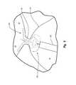
- FIG. 1Cprovides a view of the crescent-shaped, overhanging configuration of the septum secundum 54 from within the right atrium 30 in a heart 10 having a PFO 50 .
- the septum secundum 54is defined by its inferior aspect 55 , corresponding with the solid line in FIG. 1C , and its superior aspect 53 represented by the phantom line, which is its attachment location to the septum primum 52 .
- the septum secundum 54 and septum primum 52blend together at the ends of the septum secundum 54 .
- the anterior end 56 a and posterior end 56 pare referred to herein as “merger points” for the septum secundum 54 and septum primum 52 .
- the length of the overhang of the septum secundum 54which is the distance between superior aspect 53 and inferior aspect 55 , increases towards the center portion of the septum secundum as shown.
- the tunnel 58 between the right atrium 30 and left atrium 40is defined by portions of the septum primum 52 and septum secundum 54 between the merger points 56 a and 56 p which have failed to fuse.
- the tunnel 58is often at the apex of the septum secundum 54 as shown.
- the portion of the septum secundum 54 to the left of tunnel 58which is referred to herein as the posterior portion 57 p of the septum secundum, is longer than the portion of the septum secundum 54 to the right of tunnel 58 , which is referred to herein as the anterior portion 57 a of the septum secundum 54 .
- the posterior portion 57 palso typically has a more gradual taper than the anterior portion 57 a as shown.
- the anterior pocket 59 ais the area defined by the overhang of the anterior portion 57 a of the septum secundum 54 and the septum primum 52 , and it extends from the anterior merger point 56 a toward the tunnel 58 .
- the posterior pocket 59 pis the area defined by the overhang of the posterior portion 57 p of septum secundum 54 and the septum primum 52 , and it extends from the posterior merger point 56 p toward the tunnel 58 .
- the inventionrelates to a medical system, devices and methods of use for reducing the size of an internal tissue opening, such as a Patent Foramen Ovale (“PFO”).
- the medical systemcan include a closure device and an associated delivery device.
- the medical systemcan be configured to enable a practitioner to selectively position and deploy the closure device in an internal tissue opening to approximate, or in other words bring together the tissue of the opening.
- the closure devicecan include a multi-cellular body portion operatively associated with a first anchor and a second anchor.
- the multi-cellular body portioncan be configured to enable the closure device to collapse into a relatively narrow non-deployed orientation and expand into a deployed or expanded orientation without plastic deformation or failure of the closure device.
- the first and second anchorscan be configured to engage at least a portion of a wall of the internal tissue opening and/or tissue, such as tunnel tissue, of the opening.
- the closure devicecan be a non-tubular, substantially flat stent.
- the closure devicecan include an ingrowth material to facilitate tissue growth.
- the closure devicecan also include one or more indicators to facilitate the estimation of the position and/or orientation of the closure device with respect to the internal tissue opening.
- the delivery devicecan include a delivery assembly, an actuating assembly, and a release assembly operatively associated with a handle body.
- the delivery assemblyfacilitates selective delivery of the closure device from the delivery device, and is operatively associated with the actuating assembly and the release assembly.
- the actuating assemblyinteracts with the handle body to selectively deploy the closure device from the delivery assembly.
- the actuating assemblycan be configured to deploy at least a portion of the closure device by a first movement and deploy a second portion of the closure device by a second movement.
- the release assemblycan be linked to the handle body to facilitate detachment of the closure device from the delivery device.
- the closure deviceis linked to the delivery device by one or more tethers and one or more wires, the tethers being coupled to the handle body and the wires being coupled to a biasing member of the release assembly.
- the tetherscan be configured to receive a portion of the closure device therein to facilitate securement of the closure device to the delivery device.
- the wirescan be detachably coupled to the closure device to enable selective detachment of the closure device from the delivery device by movement of the biasing member.
- FIGS. 1A-1Cillustrate exemplary views of a heart having a Patent Foramen Ovale
- FIG. 2illustrates a perspective view of an embodiment of a medical system according to the present invention
- FIG. 3Aillustrates an embodiment of a closure device according to the present invention
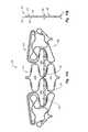
- FIG. 3Billustrates an embodiment of a closure device in a non-deployed orientation according to the present invention
- FIG. 3Cillustrates a cut-out view of a portion of a closure device according to the present invention
- FIG. 4illustrates an embodiment of a delivery device according to the present invention
- FIGS. 5A-5Cillustrate cross-sectional views of a delivery device according to the present invention
- FIG. 6illustrates an exploded view of a delivery device according to the present invention
- FIG. 7illustrates an embodiment of a coupling system according to the present invention
- FIG. 8Aillustrates an embodiment of a closure device being partially deployed in an internal tissue opening
- FIG. 8Billustrates an embodiment of a delivery device in an orientation corresponding to the partially deployed closure device of FIG. 8A ;
- FIG. 9illustrates an embodiment of a partially deployed closure device according to the present invention.
- FIG. 10Aillustrates an embodiment of a closure device positioned in an internal tissue opening
- FIG. 10Billustrates an embodiment of a delivery device in an orientation corresponding to the deployed and detached closure device of FIG. 10A ;
- FIG. 11Aillustrates an embodiment of a closure device having an ingrowth material according to the present invention.
- FIG. 11Billustrates a side view of the closure device of FIG. 11A .
- the present inventionextends to medical systems, methods, and apparatus for reducing the size of an internal tissue opening.
- the devices disclosed hereincan be used to treat a variety of internal tissue openings, such as a left atrial appendage, paravalvular leaks, PDA's, and VSD's, for example.
- internal tissue openingssuch as a left atrial appendage, paravalvular leaks, PDA's, and VSD's, for example.
- PFOPatent Foramen Ovale
- references to PFO openingsare not limiting of the invention.
- FIG. 2is a perspective view of a medical system 100 configured to facilitate closure of an internal tissue opening according to one embodiment of the present invention.
- the medical system 100comprises a closure device 200 adapted to reduce the size of the internal tissue opening, and a delivery device 300 adapted to facilitate placement and deployment of the closure device 200 with respect to the internal tissue opening.
- the medical system 100 of the present inventioncan provide benefits.
- the medical system 100can be configured to be used with different sizes, shapes and types of internal tissue openings.
- the medical system 100can provide various safety measures to increase the safety and effectiveness of positioning the closure device 200 .
- the medical system 100can be configured to provide distributed lateral force to tissue of the internal tissue opening.
- delivery device 300comprises a handle body 302 , an actuating assembly 320 operatively associated with handle body 302 , a release assembly 340 operatively associated with the handle body 302 and a delivery assembly 360 operatively associated with the actuating assembly 320 , the release assembly 340 and the handle body 302 .
- Handle body 302can be configured to provide a gripping surface for a user.
- Handle body 302can be used to position closure device 200 , as well as facilitate deployment of the closure device 200 from the delivery assembly 360 .
- Actuating assembly 320can be moved with respect to handle body 302 to selectively deploy portions of the closure device 200 from the delivery assembly 360 , as will be discussed more fully herein below.
- Release assembly 340can be operatively associated with the handle body 302 to enable selective detachment of closure device 200 from the delivery assembly 360 .
- Delivery assembly 360can house closure device 200 in a non-deployed or constrained orientation, such as illustrated in FIG. 3B for example, and facilitate deployment of closure device 200 .
- Delivery assembly 360can include one or more tethers 364 linked to the closure device 200 to facilitate selective detachment of the closure device 200 from the delivery device 300 .
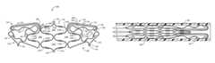
- the closure device 200is illustrated in a fully deployed, expanded, relaxed or non-constrained orientation.
- the closure device 200can be configured to reduce the size of an internal tissue opening so as to close the internal tissue opening.
- the closure device 200can reduce the size of an internal tissue opening by approximating, or in other words bringing together tissue of the internal tissue opening, such as tunnel tissue in a PFO.
- the closure device 200can approximate tissue by applying lateral force to tissue of the internal tissue opening, as will be discussed more fully herein after.
- the closure device 200can be configured to enable a user to estimate the position and/or orientation of the closure device 200 with respect to an internal tissue opening, during and after positioning of the closure device 200 in the internal tissue opening.
- the closure device 200can be a non-tubular stent.
- the closure device 200can be configured to assume a substantially flat configuration, or in other words be configured to be substantially planar, such as illustrated in FIGS. 3A and 11B for example.
- the closure device 200can be configured to resist movement out of plane, such as plane 260 of FIG. 11B .
- the closure device 200may bend out of plane when positioned in a tissue opening.
- the closure device 200has many advantages.
- the closure device 200can be configured to be reliable and compliant.
- the configuration of the closure device 200can enable the closure device 200 to be movable between a non-deployed orientation and a deployed orientation without causing failure or plastic deformation of the closure device 200 .
- the closure device 200can be used to close various types, shapes and sizes of internal tissue openings.
- the closure device 200can accommodate for a range of PFO tunnel lengths, for example.
- the closure device 200can be partially or fully deployed from or received back into the delivery device 300 .
- Closure device 200can be configured to substantially conform to the size and shape of a tissue opening.
- the undulations on the distal and proximal anchorscan enable the anchors to substantially, or to a certain degree, conform to the anatomy of a tissue opening.
- the closure device 200can have a substantially flat aspect having a length and height greater than its depth or depth thickness.
- the closure device 200has an overall length of 22 mm, a height of 7.5 mm and a depth thickness of 0.4 mm.
- the distance between the opposing ends of the proximal anchor 218can be about 22 mm
- the distance between the most proximal attachment member 240 of the body portion 202 and the most distal indicator 220 of the body portion 202can be about 7.5 mm
- the depth thickness, designated as DT in FIG. 11Bof the closure device 200 can be about 0.4 mm.
- the majority of segments comprising the closure device 200can have a thickness or width that is substantially less than the depth thickness of the segments.
- the closure device 200can resist out of plane movement due to the size and configuration of the segments.
- the closure device 200can be configured to assume a substantially flat configuration in a first plane.
- the configuration of the segmentsfor example the segments having a certain depth thickness, can facilitate the closure device 200 resisting movement out of the first plane in a manner similar to an I beam resisting bending in the direction of the web of the beam.
- the first planecan be plane 260 as illustrated in FIG. 11B .
- the closure device 200can have a unitary construction.
- the closure device 200can be cut from a single piece of material, such as cut by a laser, thereby removing the need to assemble or join different segments together.
- a unitary constructioncan provide advantages, such as ease of manufacturing and reliability. For example, assembly is not required for a closure device having a unitary construction. Also, a closure device having a unitary construction may not include distinct elements or segments which require joining by joints, thereby reducing a likelihood of failure.
- the closure device 200can be made from a super-elastic material, such as a super-elastic metal or a super-elastic polymer.
- the closure device 200can be made from NiTiNol, stainless steel alloys, magnesium alloys, and polymers including bio-resorbable polymers.
- the closure devicecan be formed by utilizing a pressurized stream of water, such as a water jet, to remove material from a piece of material to form the closure device.
- a pressurized stream of watersuch as a water jet
- the closure devicecan be formed by utilizing one or more of the following: die casting, chemical etching, photolithography, electrical discharge machining, or other manufacturing techniques. It is contemplated that the closure device can be formed through use of a mill or some other type of device adapted to remove material to form a desired shape.
- the closure device 200can comprise multiple segments joined together by a known joining process, such as by an adhesive, by interference fits, crimping, by fasteners, or a weld, or some combination thereof.
- the closure devicecan include multiple segments joined together by various welds to form a closure device according to the present invention.
- the segmentscan be joined together by a plurality of means, such as by the combination of welding, fasteners, and/or adhesives.
- the segmentscan be a wire or multiple joined or rolled wires crimped together or joined by a joining process to form the closure device 200 .
- the closure device 200includes a body portion 202 , a first anchor 204 operatively associated with the body portion 202 and a second anchor 206 operatively associated with the body portion 202 .
- the body portion 202can be configured to facilitate application of lateral force against tissue of an internal tissue opening.
- the body portion 202can be configured to enable the closure device 200 be movable between a non-deployed and deployed orientation.
- the closure device 200can be configured to be self-expanding from the constrained or non-deployed orientation, as illustrated in FIG. 3B for example, to the relaxed orientation, as illustrated in FIG. 3A .
- the closure device 200can have a preferential orientation, such that movement of the closure device 200 from a first orientation to a second orientation can create internal stresses in the closure device 200 . These internal stresses can serve to bias the closure device 200 to the first orientation.
- the closure device 200can have a preferential orientation of the relaxed or fully deployed orientation as illustrated in FIG. 3A .
- movement of the closure device 200 to a constrained orientationsuch as illustrated in FIG. 3B for example, can create internal stresses in the closure device 200 , thereby creating in the closure device 200 a bias to return to the relaxed orientation.
- body portion 202includes one or more cells 208 defined by a plurality of segments 210 .
- the body portion 202can include one or more apertures.
- an apertureis defined by the cell 208 , or in other words by the plurality of segments 210 .
- segment 210can be a strut or a body support segment.
- Cells 208can be distinct, or can be at least partially defined by a common segment.
- cell 208 Aas the distal most cell
- cell 208 Cas the proximal most cell of body portion 202
- cell 208 Bis partially defined by a segment 210 C which also defines a portion of cell 208 A.
- cell 208 Bis partially defined by a segment 210 G which also partially defines cell 208 C.
- cell 208 Dshares a segment 210 D with cell 208 A and shares a segment 210 H with cell 208 C.
- Segments 210can be shaped and configured to have a substantially uniform stress at any given point along a certain length, when the segment 210 is deflected.
- segment 210 Acan include a first portion 230 having a width or thickness greater than a second portion 232 , wherein the width or thickness decreases from the first portion 230 to the second portion 232 , or in other words is tapered, in a manner which provides for substantially uniform stress levels along the certain length.
- segmentscan have a substantially constant width along their length.
- FIG. 3Cis a cut-out view of a portion of the closure device 200 , including the first portion 230 and the second portion 232 of segment 210 A.
- the width or thickness of the segment 210 Avaries along the portion of the segment 210 A from the location where segment 210 A extends from the portion 254 which joins segment 210 A to segment 210 C to the intermediate portion 234 .
- the segments 210are deflected, with the highest levels of stress in the segment 210 being concentrated at the joining portion 254 and decreasing towards the intermediate portion 234 .
- the segments 210can be configured in a manner so as to have a substantially equal stress level along the length of the segment 210 between the joining portion 254 and the intermediate portion 234 .
- the uniform stress levelcan be accomplished by having the width of the segment 210 vary from the first portion 230 to the second portion 232 in a calculated manner.
- the width of the first portion 230 of the segmentcan be about 0.1 mm and the taper to a width of about 0.05 mm at the second portion 232 of the segment.
- the uniform stress levelcan be accomplished by utilizing a gradient of material having varying properties.
- the segment 210can have varying widths along its length and comprise a gradient of material sufficient to achieve a substantially uniform stress level between the first portion 230 and the second portion 232 of the segment.
- the first portionis adjacent the joining portion 254 and the second portion is adjacent the intermediate portion 234 .
- the joints of the interconnecting segmentscan include a biasing member, such as a spring, thereby enabling the segments to move relative to each other to collapse or expand the closure device 200 .
- the biasing member of the jointcan cause the segments to have a preferential orientation with respect to each other.
- segments 210can also be configured to have a rectangular cross-section. In other embodiments, segments 210 can have an oval shaped cross section. In yet another embodiment, sections 210 can have a round or rounded cross section.
- the ratio, or aspect ratio, of the thickness or width to the depth thickness of the first and second portions 230 , 232can range between at least about 1:2 to about 1:20. In one embodiment, the aspect ratio of the width to the depth thickness of the first portion 230 can be at least 1:2 and the ratio of the width to the depth thickness of the second portion 232 can be at least 1:4.
- the aspect ratio of the first portion 230can be about 1:4 and the aspect ratio of the second portion 232 can be about 1:8. In this manner, the closure device 200 can substantially resist out of plane movement, while allowing in-plane movement during reorientation of various portions of the closure device 200 .
- Segments 210can be configured to be compliant. Compliancy of segments 210 can enable cells 208 , and thus the body portion 202 , to be oriented in various orientations. For example, body portion 202 can be oriented, or in other words moved, between a non-deployed orientation, such as illustrated in FIG. 3B , and a fully deployed orientation, such as illustrated in FIG. 3A . The compliancy of segments 210 can facilitate the accommodation by the closure device 200 of a variety of types, shapes and sizes of internal tissue openings. For example, the size and configuration of the first and second anchors 204 , 206 and the body portion 202 can enable the closure device 200 to accommodate varying sizes, shapes and types of internal tissue openings.
- the first anchor 204can engage wall tissue of an internal tissue opening and the second anchor 206 can engage only the tunnel tissue of the internal tissue opening to approximate tissue.
- the second anchor 206can engage the tunnel tissue and an opposing wall of the internal tissue opening to approximate tissue.
- Segments 210can include an intermediate portion 234 configured to facilitate securement of ingrowth materials to the closure device 200 , or can be used as an indicator 220 to facilitate estimation of the position of the closure device 200 with respect to an internal tissue opening. Furthermore, intermediate portion 234 can be configured to facilitate measuring of a characteristic of an internal tissue opening. In one embodiment, intermediate portion 234 can include one or more apertures. The apertures can be configured to receive a securing element, such as a thread, therethrough to facilitate securing an ingrowth material to the closure device 200 . Intermediate portion 234 can be configured to be stiffer or more rigid than first portion 230 , second portion 232 , or both. A stiffer intermediate portion 234 can increase the reliability of segments 210 .
- the intermediate portion 234can include an indicator 220 , such as a dense metallic rivet or concentration of dense material, for use in estimating the orientation and/or position of the closure device 200 .
- an indicator 220such as a dense metallic rivet or concentration of dense material
- Understanding of the orientation and/or position of the closure device 200can facilitate estimating a physical characteristic of an internal tissue opening and/or the relative position of the closure device 200 with respect to the internal tissue opening. For example, if the distance between the indicators 220 is known, a practitioner can estimate a physical characteristic, such as the opening or tunnel width, by determining the new distance between the indicators 220 when the closure device 200 is positioned in the tissue opening.
- indicators 220can be positioned on the first and second anchors 04 , 206 . The indicators 220 can be configured and arranged on the closure device 200 such that when the first anchor 204 is deployed the indicators 220 are substantially aligned. In this manner, a practitioner can estimate whether the first anchor 204 has fully deployed.
- closure device 200it may be difficult to view the closure device 200 in the event the closure device 200 is at a skewed angle with respect to the viewing plane, such as a fluoroscope.
- a fluoroscopeWhen the closure device 200 is skewed in this manner, it can be difficult to determine accurately the distance of interest.
- a usercan use the known distances to calculate the distances of interest by using geometry.
- segments 210 along a similar or common lateral planecan have substantially equal lengths. Substantially equal lengths of segments 210 in this manner can enable body portion 202 to be moved between the non-deployed and deployed orientation without failure of the segments 210 .
- segments 210 A and 210 Bhave substantially the same length
- segments 210 E, 210 C, 210 D, and 210 Khave substantially the same length
- segments 210 F, 210 G, 210 H and 210 Lhave substantially the same length
- segments 210 I and 210 Jhave substantially the same length.
- body portion 202can be collapsed or oriented into the non-deployed orientation, as illustrated in FIG. 3B , without causing damage to the body portion 202 of closure device.
- the closure device 200can be configured to have a preferential orientation of the fully deployed orientation as illustrated in FIG. 3A .
- the configuration of closure device 200can cause the closure device 200 to preferentially move toward the fully deployed orientation.
- the preferential orientation of the closure device 200can cause the closure device 200 to apply lateral force to the tissue of the internal tissue opening.
- the body portion 202 , first anchor 204 and the second anchor 206are deflected by an applied force in order to reorient the closure device 200 from the fully deployed orientation to a non-deployed orientation, for example.
- the closure device 200because of the deflection of the body portion 202 , first anchor 204 and the second anchor 206 , will have tendency to return to the fully deployed orientation.
- the deflected body portion 202 , first anchor 204 and the second anchor 206can have a tendency to apply a lateral force to tissue of the opening as the closure device 200 attempts to return to the fully deployed orientation.
- Body portion 202can be operatively associated with the first anchor 204 and the second anchor 206 .
- First and second anchors 204 , 206can be configured to move between a deployed and non-deployed orientation.
- First and second anchors 204 , 206can be configured to apply lateral force to tissue of an internal tissue opening, and to engage and/or contact a portion of wall tissue and/or tunnel tissue of an internal tissue opening.
- the first anchor 204can be a left atrial anchor
- the second anchor 206can be a right atrial anchor.
- the first anchor 204can include a first anchor segment 212 and an opposing second anchor segment 214 .
- the second anchor 206can include a first anchor member 216 and an opposing second anchor member 218 .
- the first anchor segment 212can be configured to move relative to the second anchor segment 214 .
- the first anchor member 216can be configured to move relative to the second anchor member 218 .
- the closure device 200can accommodate for a variety of types, shapes and sizes of internal tissue openings.
- the first anchor segment 212 and the second anchor segment 214can be configured to be substantially similar in size, shape and configuration. As such, reference to the configuration and/or function of one of the first or second anchor segments can apply to the other anchor segment.
- the first anchor 204 and/or the second anchor 206can include one or more undulations.
- the undulationscan facilitate reorienting or movement of the anchors with respect to the body portion 202 , for example, from a deployed to a non-deployed configuration. Furthermore, the undulations can facilitate the anchor substantially conforming to the anatomy of the tissue opening.
- the first anchor segment 212can include a distal end 224 and a proximal end 226 .
- the first anchor segment 212can be defined by various segments and can include reinforced segments 228 and one or more engaging members 222 .
- the first anchor segment 212is at least partially defined by segment 210 K of cell 208 D.
- the engaging members 222can be microposts or tines configured to contact and/or engage tissue.
- the engaging members 222can include a sharp tip or can be blunt.
- the engaging members 222can be configured to provide a degree of surface texture in order to increase engagement of the first anchor 204 with tissue.
- the first anchor segment 212can be configured to be moved between a non-deployed orientation, as illustrated in FIG. 3B , and a fully deployed orientation, as illustrated in FIG. 3A .
- the first anchor segment 212can be configured such that the distance from the proximal end 226 to the distal end 224 of the segment which includes the engaging members 222 is substantially equal to the distance from the proximal end 226 to the distal end 224 of the segment which includes the reinforced segments 228 and segment 210 K.
- the second anchor segment 214can be configured similar to the first anchor segment 212 .
- First anchor segment 212can be configured to define a closed periphery.
- first anchor segment 212can include the reinforced segment 228 extending from the body portion 202 to the segment having the engaging members 222 which is connected to segments 210 K, 210 L to define a closed periphery with segment 210 K.
- two reinforced segments 228can extend from the joining portion 254 of the body portion 202 and join together near the distal end 224 of the first anchor 204 .
- anchors of the present inventionare reinforced to provide greater rigidity and strength to facilitate stabilization and maintenance of the closure device 200 within a tissue structure.
- First anchor member 216can include a distal end 236 and a proximal end 238 .
- the first anchor member 216can be defined by various segments and can include one or more engaging members 222 .
- the first anchor member 216is at least partially defined by segment 210 L of cell 208 D.
- the engaging members 222can be microposts or tines configured to contact and/or engage tissue.
- the engaging members 222can include a sharp tip or can be blunt.
- the engaging members 222can be configured to provide a degree of surface texture to increase engagement of the second anchor 206 with tissue.
- the engaging members 222can vary in size and shape, and can be positioned at various locations on the closure device 200 .
- one or more engaging memberscan extend out of plane of the closure device so as to contact tissue which is perpendicular, for example, to the substantially flat plane, such as plane 260 of FIG. 11B , of the closure device 200 .
- the first anchor member 216can be configured to be moved between a non-deployed orientation, as illustrated in FIG. 3B , and a fully deployed orientation, as illustrated in FIG. 3A .
- the first anchor member 216can be configured such that the distance from the proximal end 238 to the distal end 236 of the segment which includes the engaging members 222 is substantially equal to the distance from the proximal end 238 to the distal end 236 of the segment which includes segment 210 L. In this manner, first anchor member 216 can be detachably coupled to the delivery device 300 when in a non-deployed orientation inside the delivery device 300 as illustrated in FIG. 3B .
- the second anchor member 218can be configured similar to the first anchor member 216 .
- the first anchor segment 212can also include a first portion 256 and a second portion 258 configured to facilitate engagement of the internal tissue opening.
- first anchor segment 212can be configured to include one or more undulations causing the first portion 256 to be positioned in close proximity with second portion 258 . In this manner, as tissue is positioned between the first and second portions 256 , 258 , the configuration of the first anchor segment 212 can engage, or to some degree, pinch the tissue therebetween to facilitate maintenance of the position of the closure device 200 with respect to the tissue opening.
- the closure device 200can also include attachment members 240 for use in detachably linking the closure device 200 to the delivery device 300 , as will be discussed more fully herein after.
- the attachment members 240can include an aperture 242 for use in facilitating the linking of the closure device 200 to the delivery device 300 .
- FIG. 3Billustrates the closure device 200 in a non-deployed or constrained orientation.
- the configuration of the body portion 202 , and the first and second anchors 204 , 206enables the closure device 200 be reoriented from the fully deployed and preferential orientation, as illustrated in FIG. 3A , to the non-deployed or collapsed orientation as illustrated.
- the first anchor 204extends distally and the second anchor 206 extends proximally, with the attachment members 240 being the proximal most portions of the second anchor 206 and the body portion 202 .
- the closure device 200is positioned inside of a delivery portion 366 of the delivery device 300 .
- the configuration of the closure device 200can cause portions of the closure device to apply force to the wall of the delivery portion 366 due to the preferential orientation of the closure device 200 .
- the closure device 200is configured to be received into and deployable from the delivery portion 366 .
- FIG. 4illustrates one embodiment of the delivery device 300 .
- the delivery assembly 360includes a catheter 362 having a delivery portion 366 , and a plurality of tethers 364 at least partially housed by the catheter 362 .
- the tethers 364can be configured to facilitate selective detachment of the closure device 200 from the delivery device 300 .
- the delivery portion 366can be configured to receive the closure device 200 therein.
- the catheter 362can be coupled to the actuating assembly 320 , such that movement of the actuating assembly 320 can cause movement of the catheter 362 .
- the actuating assembly 320includes a first member 322 operatively associated with the handle body 302 , a second member 324 operatively associated with the first member 322 and the handle body 302 , and a knob 338 linked to the first member 322 .
- the actuating assembly 320can be utilized by a user to selectively deploy the closure device 200 from the catheter 362 .
- the handle body 302can include indicia 304 to enable a user to estimate the degree of deployment of the closure device 200 from the delivery device 300 , as well as predict detachment of the closure device 200 from the delivery device 300 .
- indicia 304can include deployment indicia 306 and release indicia 308 .
- Deployment indicia 306can be utilized to enable a user to estimate the degree of deployment of the closure device 200 from the catheter 362
- the release indicia 308can be utilized to predict the detachment of the closure device 200 from the delivery device 300 .
- the handle body 302can also include a release pin groove 310 .
- the release pin groove 310can be operatively associated with the release assembly 340 to facilitate the selective detachment of the closure device 200 from the tethers 364 .
- the release assembly 340can include a biasing member 342 operatively associated with the handle body 302 to facilitate detachment of the closure device 200 .
- a release knob 346can be provided to manipulate the position of biasing member 342 in order to release or detach the closure device 200 .
- the release knob 346is coupled to the biasing member 342 , such that movement of the release knob 346 can cause movement of the biasing member 342 .
- the biasing member 342can include a release pin 344 configured to be received in, influenced by and movable in the release pin groove 310 . In this manner, release pin groove 310 can restrict, and thereby influence the movement of the biasing member 342 with respect to the handle body 302 .
- the biasing member 342is configured to interact with the handle body 302 such that when the release pin 344 is positioned in a terminating portion of the release pin groove 310 , as illustrated in FIG. 4 , the biasing member 342 is biased in the proximal direction with respect to the handle body 302 . In this manner, the release pin 344 can be moved from the terminating portion of the release pin groove 310 , as illustrated in FIG. 4 , to the opposing terminating portion of the release pin groove 310 adjacent the release indicia 308 B by applying force to the biasing member 342 through the release knob 346 in the distal direction, rotating the release knob 346 and then moving the release knob 346 in the proximal direction to release the closure device 200 , as illustrated in FIG. 10B .
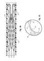
- FIG. 5Ais a cross-sectional view of the distal end of the catheter 362 .
- the catheter 362includes a delivery portion 366 for use in positioning the catheter 362 .
- the catheter 362can be made from a resilient material having sufficient axial stiffness to allow a practitioner to position the catheter 362 with respect to an internal tissue opening, and sufficient rotational stiffness to allow a practitioner to rotate the catheter 362 by rotating the handle body 302 .
- the catheter 362comprises a braided polyimide.
- the catheter 362can be made from a material having a sufficient axial stiffness, such as a braid reinforced polymer, axially reinforced polymer, metal reinforced polymer, carbon reinforced polymer, or some other type of axially stiff material.
- the delivery portion 366can be made from a thermoplastic elastomer, such as PEBAX®.
- the delivery portion or tip portion 366can be made from a material having sufficient flexible properties, such as a polymeric material.
- the delivery portion 366can include a combination of materials, such as metallic materials and polymeric materials.
- the delivery portion 366can define a lumen 368 to facilitate placement of the catheter 362 .
- a guidewirecan be received in the lumen 368 to guide the catheter 362 to a desired location.
- the closure device 200can be located proximate to the internal tissue opening in a quick and efficient manner.
- the delivery portion 366can be shaped, such as including a bend, in order to facilitate placement of the delivery portion 366 through a PFO, for example.
- the catheter 362can be considered a rapid exchange catheter wherein the delivery or tip portion 366 enables a guidewire to be linked to the catheter 362 in a quick and efficient manner for placement of the catheter 362 .
- the catheter 362 and delivery portion 366can be configured to at least partially house tethers 364 in a lumen which is distinct and separate from lumen 368 .
- lumen 368can be in a spaced apart, non-coaxial arrangement from the lumen which houses tethers 364 , such that a guidewire can be received through lumen 368 without being introduced into the lumen or space in which the tethers 364 are housed.
- a usercan introduce a guidewire into the lumen 368 at the distal end of the catheter 362 , rather than the lumen which at least partially houses the tethers 364 which would require the guidewire to be introduced into the lumen at the proximal end of the catheter 362 .
- the lumen 368 configured to receive the guidewire thereincan be positioned inside the lumen which houses the tethers 364 .
- lumen 368would include an opening and an exit at the distal end of the catheter 362 in order to facilitate the quick placement of a guidewire through the lumen 368 .
- catheter 362can include a rounded cross-section and the delivery portion 366 can include a rectangular cross-section.
- the rectangular cross-section of the delivery portion 366can facilitate proper deployment of the closure device 200 from the delivery device 300 , as well as facilitate the closure device 200 being reintroduced back into the delivery portion 366 .
- the rectangular cross-section of the delivery portion 366can be sized to orient the tethers 364 next to each other in a linear fashion. In this manner, the likelihood that the tethers 364 cross each other upon reintroduction of the closure device 200 into the delivery portion 366 can be reduced.
- tethers 364includes three tethers 364 A-C, each tether 364 being sized and configured to attach to and/or accommodate therein an attachment member 240 of the closure device 200 .
- a tetheris a line or hollow tube coupled to the handle body 302 .
- the tether 364can comprise a flexible, hollow shaft having sufficient stiffness such that as actuating assembly 320 moves the catheter 362 proximally with respect to the handle body 302 , the closure device 200 is forced out of the delivery portion 366 .
- the tether 364can be configured to pull the closure device 200 back into the delivery portion 366 as the actuating assembly 320 is moved distally with respect to the handle body 302 .
- the tether 364can be a coil of stainless steel covered by a heatshrunk tubing to give the coil a degree of tensile strength and rigidity.
- the tether 364can be a polymeric tube.
- the tether 364can be a combination of polymeric materials and metallic materials.
- an additional heatshrunk tubingcovers a proximal segment of the three tethers 364 A-C. The heatshrunk covering can increase the column strength of the tether 364 , which can enable the tethers 364 to assist with deployment and reintroduction of the closure device 200 from and into the delivery portion 366 .
- the tethers 364can have a distal tip configured to correspond to the shape and size of the attachment members 240 of the closure device, such that the attachment member 240 can be received into the distal tip of the tether 364 , as illustrated in FIG. 7 .
- Tethers 364can be made from a material having sufficient flexibility to substantially prevent distortion or otherwise influence the orientation of the closure device 200 when the closure device is deployed from the catheter 362 , yet have sufficient axial strength to facilitate deployment of the closure device 200 when the catheter 362 is moved proximally with respect to the closure device 200 .
- the tethers 364can have a lumen extending therethrough of sufficient size and configuration to enable a plurality of wires 378 to be housed and movable therein.
- FIGS. 5B-5Care cross-sectional views illustrating the delivery assembly 360 in association with the actuating assembly 320 .
- FIG. 5Bdoes not include the biasing member 342 and associated release knob 346
- FIG. 5Cillustrates details about the interaction between the delivery assembly 360 and the actuating assembly 320 without illustrating the first member 322 and details about the handle body 302 and the second member 324 .
- the proximal end of the catheter 362is coupled to the distal end of the second member 324 .
- movement of the second member 324can cause a corresponding movement in the catheter 362 .
- the catheter 362move proximally with respect to the handle body 302 .
- the tethers 364can extend from the delivery portion 366 , through the catheter 362 and the second member 324 and are coupled to the handle body 302 .
- the tethers 364can be coupled to the handle body 302 by, for example, an intermediate member 376 .
- the tethers 364can be covered with a first and second housing 370 , 372 to provide a degree of rigidity to the portions of the tethers 364 located inside of the handle body 302 and the second member 324 .
- the first housing 370comprises a rigid, hollow, metal rod configured to house the three tethers 364 A-C therein.
- the first housing 370can extend from the intermediate member 376 , which facilitates securement of the tethers 364 to the handle body 302 , and terminate at some point beyond the handle body 302 .
- the second housing 372can extend from the distal end of the first housing 370 and extend into the catheter 362 .
- the second housing 372can comprise a resilient material configured to resist axial stretching while allowing a degree of bending.
- the second housing 372comprises a coil of metal, such as stainless steel, configured to resist axial stretching, yet allow a degree of bending.
- the second housing 372can allow a practitioner to bend a portion of the catheter 362 , if needed, in order to manipulate delivery device 300 for placement of the closure device 200 .
- a seal 374can be provided between the first housing 372 and the second member 324 in order to reduce or substantially prevent bodily fluid, which may have entered the catheter 362 , from entering the handle body 302 or otherwise inappropriately being expelled from the delivery device 300 .
- the second member 324can comprise an elongate shaft defining an axial lumen 348 and a lumen 350 in fluid communication therewith.
- Lumen 350can be configured to couple to a medical device for removal of fluid from the delivery device 300 .
- the axial lumen 348can be sized to accommodate and allow movement of the tethers 362 , the first housing 370 and the second housing 372 therein.
- the second member 324can include a guide 326 .
- the guide 326can be configured to cooperate with a first pin 352 and a second pin 354 to influence movement of the second member 324 with respect to the handle body 302 , as will be discussed more fully herein below.
- the first member 322comprises a hollow elongate tube sized and configured to enable the second member 324 to be received into and moveable within the first member 322 .
- the first member 322can be operatively associated with the handle body 302 and the second member 324 to facilitate deployment of the closure device 200 .
- the first member 322is linked to the handle body 302 by a third pin 356 .
- the third pin 356is received in a guide 358 of the first member 322 .
- the guide 358is configured to interact with the third pin 356 in order to influence the movement of the first member 322 with respect to the handle body 302 .
- the first pin 352can link the first member 322 to the second member 324 .
- the second pin 354links the handle body 302 to the second member 324
- the third pin 356links the handle body 302 to the second member 322 .
- FIG. 6is an exploded view of the actuating assembly 320 and the release assembly 340 .
- the second member 324is received into the first member 322
- the first member 322is received into the knob 338 and the handle body 302 , as illustrated in FIGS. 4 and 5 B- 5 C.
- the second member 324can include a guide 326 having a first portion 326 a and a second portion 326 b , which guide 326 can be defined by a slot formed on the outer surface of the second member 324 .
- the first portion 326 ais straight and extends along at least a portion of the length of the first member 324 and joins with the second portion 326 b of the guide 326 .
- the second portion 326 bcan include a helical groove or slot that begins with and is contiguous with the first portion 326 a and extends distally therefrom.
- the guide 326 of the second member 324is configured to interact with the handle body 302 and the first member 322 to selectively retract the catheter 362 in order to deploy the closure device 200 .
- the first portion 326 a of the guide 326is configured to interact with the second pin 354 , which is secured into the handle body 302 by means of threads and extend into the first portion 326 a of the guide 326 .
- the second member 324can move laterally with respect to the handle body 302 .
- rotation of the handle body 302can translate to rotation of the second member 324 , and thus, the catheter 362 and the delivery portion 366 .
- the second portion 326 b of the guide 326is configured to interact with the first pin 352 , which is secured to the first member 322 by means of threads and extends into the second portion 326 b of the guide 326 .
- the first pin 352will interact with the second portion 326 b to move the second member 324 in the proximal direction.
- the catheter 362moves proximally with respect to the handle body 302 thereby exposing or deploying the closure device 200 from the delivery portion 366 .
- the first member 322can include a guide 358 defined by a slot or groove formed in the outer surface of the first member 322 .
- the guide 358can include a first portion 358 a connected to a second portion 358 b .
- the first portion 358 a of guide 358can be straight and extend along at least a portion of the length of the first member 322 , and then join and be contiguous with the second portion 358 b .
- the second portion 358 b of the guide 358can be a helical groove that wraps around at least a portion of the outer surface of the first member 322 and extends along at least a portion of the length of the first member 322 .
- the third pin 356which is secured to the handle body 302 by means of threads, can extend into the guide 358 in order to influence movement of the first member 322 with respect to the handle body 302 .
- the closure device 200is completely received into and enclosed by the delivery portion 366 .
- the third pin 356moves in the first portion 358 a of the guide 358 to deploy the first anchor 204 of the closure device 200 from the delivery portion 366 .
- the length of the first portion 358 acan correspond with the distance that the first member 322 , and thus the catheter 362 , must move in order to deploy the first anchor 204 of the closure device 200 from the delivery portion 366 .
- a practitionercan move the knob 338 , which is coupled to the first member 322 , in the proximal direction. Movement of the knob 338 in the proximal direction can cause the third pin 356 to move linearly in the first portion 358 a of the guide 358 . In this manner, the second member 324 can move correspondingly with the first member 322 because of the first pin 352 , which links the first member 322 to the second member 324 .
- the first member 322can be rotated in order to selectively deploy the remaining portions of the closure device 200 from the delivery portion 366 of the delivery device 300 .
- the third pin 356is positioned in the second portion 358 b to influence movement of the first member 322 with respect to the handle body 302
- the first pin 352which is coupled to the first member 322 , interacts with the second portion 326 b of the guide 326 to move the second member 324 in the proximal direction with respect to the handle body 302 . Movement of the second member 324 in the proximal direction in this manner can cause further deployment of the closure device 200 from the delivery portion 366 .
- the knob 338can be coupled to the first member 322 to facilitate and enable movement of the first member 322 with respect to the handle body 302 .
- the dual movement required to deploy the closure device 200can provide some efficiency and safety advantages.
- a practitionercan move the knob 338 in a first direction (i.e., proximally in a linear fashion) to deploy the first anchor 204 from the delivery portion 366 .
- the practitionercan move the handle body 302 to position the first anchor 204 against the wall tissue of an internal tissue opening, such as against the left atrial wall of a heart, for example.
- the practitionercan move the knob 338 in a second direction (i.e., rotate the knob) to further deploy the closure device 200 from the delivery portion 366 .
- the dual movementenables a user to predict the deployment of the closure device 200 to reduce the risk of premature deployment of the closure device.
- a structureconfigured to substantially restrict or control movement of the first element with respect to the second element and/or handle body can be utilized.
- the structurecan include a cam and a follower.
- the structurecan include a slider.
- the release assembly 340can be configured to be received in the proximal end of the handle body 302 .
- the release assembly 340can be configured to provide additional safety features for the practitioner and patient by reducing the risk of premature detachment of the closure device 200 before it is positioned appropriately in an internal tissue opening.
- a practitioner using the medical system 100 of the present inventioncan manipulate the actuating assembly 320 to deploy the closure device 200 for positioning in an internal tissue opening.
- a usercan move the knob 338 , and thus the first member 322 , in the proximal direction with a first movement, which is a linear movement, then deploy the remaining portions of the closure device 200 by a rotational movement.
- the practitionercan be required to move their hands in order to utilize the release assembly 340 to release the closure device 200 from the delivery device 300 .
- the release assembly 340can include a release knob 346 coupled to a biasing member 342 , which is received into the proximal end of the handle body 302 .
- the biasing member 342can be configured to include a plurality of slots 318 configured and arranged to act similar to a spring.
- the slots 318can be configured and arranged in the biasing member 342 to enable at least a portion of the biasing member 342 to be compressed. Compression of the biasing member 342 can cause the release pin 344 to move toward the distal end of the biasing member 342 .
- the biasing member 342can be configured such that when biasing member 342 is positioned in the handle body 302 , the biasing member 342 naturally tends to maintain its position with the release pin 344 in the release pin groove 310 as illustrated in FIG. 4 . As force is applied to the release knob 346 in the distal direction (i.e., compress the biasing member 342 ), the release pin 344 can be moved out of a terminating portion of the release pin groove 310 and rotated and moved into a proximal terminating portion of the release pin groove 310 to release the closure device 200 from the delivery device 300 .
- the closure device 200is released from the delivery device 300 by moving a plurality of wires 378 which are housed by a tether 364 and coupled to the biasing member 342 . Illustrated in FIG. 7 is a cross-sectional view of attachment member 240 of the closure device 200 received into a tether 364 and coupled by first and second wires 378 a , 378 b .
- a second wire 378 bcan extend through and out of the tether 364 and form a loop. The loop can extend through an aperture 242 of the attachment member 240 of the closure device 200 .
- a first wire 378 awhich extends through and out of the tether 364 , can extend through the loop of the second wire 378 b to form a locking feature.
- the closure device 200can remain coupled to the delivery device 300 until the first wire 378 a is pulled through the loop of the second wire 378 b , and the second wire 378 b is pulled out of the aperture 242 of the attachment member 240 .
- the first wire 378 a and the second wire 378 bcan be attached at their proximal ends to the biasing member 342 . In this manner, movement of the biasing member 342 in the proximal direction can cause movement of the wires 378 also in the proximal direction.
- the wires 378can be coupled to the biasing member 342 such that movement of the biasing member 342 will cause the first wire 378 a to move a distance sufficient to be removed from the loop of second wire 378 b before the second wire 378 b is moved by the biasing member 342 .
- the wire 378can comprise a metallic wire, such as a NiTiNol wire.
- the wire 378can also include a stainless steel wire or some other type of metal or stiff polymer.
- the wires 378can be made from a material having a sufficient tensile strength to secure the closure device 200 to the tethers 364 without causing the wires 378 to fail or substantially deform.
- the wire 378 Bcan include a stainless steal wire and wire 378 A can include a NiTiNol wire.
- the release assemblycan include a rotating member coupled to the securing elements.
- rotation of the rotating membercan cause the securing elements to wind around the rotating member thereby causing the distal ends of the securing elements to move proximally with respect to the handle body.
- FIG. 8 aillustrates the positioning of the catheter 362 through the tunnel 58 of a PFO with the first anchor 204 of the closure device 200 deployed.
- the medical system 100is utilized to close an internal tissue opening by positioning the catheter 362 through an internal tissue opening and moving the first member 322 by a first movement (i.e., linearly) in the proximal direction to deploy the first anchor 204 of the closure device 200 .
- the delivery device 300can be moved in the proximal direction in order to seat the first anchor 204 against the wall of the tissue opening or otherwise engage the wall of the internal tissue opening, as illustrated in FIG. 9 . This can be done by moving the handle body 302 in the proximal direction.
- the knob 338and thus the first member 322 , can moved by a second movement, or in other words, rotated to deploy additional portions of the closure device 200 as illustrated in FIG. 9 .
- the release assembly 340can be actuated to selectively detach the delivery device 300 from the closure device 200 as illustrated in FIGS. 10 a and 10 b.
- the release assembly 340can be actuated by moving the biasing member 342 distally with respect to the handle body 302 , then rotating the biasing member with respect to the handle body 302 , and then moved proximally with respect to the handle body 302 .
- closure device 200substantially conforms to the anatomy of the internal tissue opening.
- the configuration of the closure device 200is such that when positioned in the internal tissue opening as illustrated, the members of the closure device 200 apply lateral force to the tissue of the internal tissue opening, such as the tunnel 58 of the PFO, to approximate tissue of the PFO for closure.
- FIG. 11Aillustrates one embodiment of a closure device 200 that can include a member 250 , such as an ingrowth material.
- the member 250can be configured to induce tissue growth.
- the member 250can be fixed to the closure device 200 by means of a securing element, such as a thread 252 .
- the thread 252can extend through the member 250 and through the apertures in the intermediate portions 234 in order to secure the member 250 to the closure device 200 .
- the member 250can be secured to the closure device 220 by a known securing means, such as by an adhesive, a heat weld, or some other known or hereafter developed means for securement.
- the member 250 and the thread 252can include a bio-resorbable material, such as polylactide or polyglycolide or collagen.
- the member 250can be sized and configured to enable the closure device 200 to be deployed from and received into the delivery portion 366 of the delivery device 300 .
- the member 250can be configured to interact with tissue of the internal tissue opening to stimulate growth of tissue for closure of the internal tissue opening.
- the member 250can interact with the tunnel tissue 58 of a PFO in order to stimulate growth of tissue in the PFO tunnel 58 .
- the member 250can be any suitable material which can or tends to promote tissue growth. Examples of such material can include a polymeric material, or a woven material, such as a woven metallic or biological material.
- the member 250can be a piece of foam.
- the member 250can be a piece of yarn, fabric or string, or some combination thereof.
- Other tissue growth promoting memberscan include a coating disposed on the closure device 200 .
- the member 250can be a piece of foam, braided material such as a piece of yarn or string, or fabric which has a coating disposed thereon.
- the member 250can include materials such as a piece of polyurethane or some other biocompatible polymer, including bio-resorbable polymers.
- the member 250can also include Dacron or polymeric threaded material which have been woven or knitted, or formed into compressed, non-woven fabrics.
- the member 250can also include a metallic material, such as a NiTiNol, stainless steal or some other biocompatible alloy or bio-resorbable metal, such as magnesium alloy, or some combination thereof.
- the member 250comprises a metallic wire.
- FIG. 11Billustrates a side view of the closure device 200 , and illustrates one example of the closure device having a substantially flat configuration.
- the closure device 200can include a depth or depth thickness designated as DT, and a plane 260 extending perpendicular into and out of the plane of the page.
- the member 250can extend beyond at least a first edge 262 of the closure device 200 .
- the member 250can extend beyond both the first edge 262 and a second edge 264 of the closure device 200 . In this manner, member 250 can contact tissue adjacent the closure device 200 to promote tissue growth in the tissue opening.
- the member 250can be sized and configured to extend beyond at least the first edge 262 of the closure device 200 a sufficient distance to contact tissue of the tissue opening. In one embodiment, the member 250 can extend beyond at least the first edge 262 a sufficient distance to contact tissue adjacent the first edge 262 , thereby causing the end of the member 250 which is in contact with the tissue to deflect or bend. In this manner, more surface area of the member 250 can be in contact with tissue to thereby facilitate an increase in tissue growth. In other embodiments, the member 250 can extend beyond both the first edge 262 and the second edge 264 a sufficient distance to cause both ends of the member 250 to bend, which can result in more surface area contacting the tissue.
- the member 250can extend between at least 0.5 mm and 5 mm beyond the first edge 262 . In another embodiment, the member 250 can extend between at least 0.5 mm and 5 mm beyond the first edge 262 , and can extend between at least 0.5 mm and 5 mm beyond the second edge 264 . Furthermore, the member 250 can have a thickness of between at least 0.25 mm and 2 mm.
- the member 250can be configured to decrease the size of a remaining void in the tissue opening after the closure device 200 has been positioned in the tissue opening.
- Member 250 extending beyond the first edge 262 of the closure device 200is an example of the member 250 extending substantially out of plane of the substantially flat configuration.
- the present inventioncan also include the following methods, systems and devices.
- a medical devicecomprising: a body portion comprising two or more cells, said body portion being movable between a deployed and non-deployed orientation; and at least one anchor linked to said body portion, said at least one anchor being adapted to reduce proximal movement of the medical device when the medical device is positioned in an internal tissue opening.
- a medical devicecomprising: a multi-cellular structure adapted to selectively expand and contract between a deployed and non-deployed orientation; a first anchor operatively associated with said multi-cellular structure, said first anchor being adapted to selectively engage at least a portion of a wall of an internal tissue opening; and a second anchor operatively associated with said multi-cellular structure, said second anchor being adapted to engage at least a portion of at least another portion of the wall of the tissue opening.
- a method for closing a Patent Foramen Ovalecomprising the steps of: positioning at least a portion of a medical device into a left atrium of a heart, said medical device comprising a first anchor, a multi-cellular structure linked to said first anchor, and a second anchor linked to said multi-cellular structure, said first anchor, said multi-cellular structure and said second anchor being adapted to selectively move between a non-deployed and deployed orientation; locating at least a portion of said first anchor against at least a portion of a left atrial wall of the heart; and locating at least a portion of said second anchor against at least a portion of at least one of a tunnel of the Patent Foramen Ovale or a right atrial wall of the heart.
- a medical device for approximating tissue of an internal tissue opening togethercomprising: a body portion comprising two or more cells, said body portion being adapted to apply lateral force to tissue of an internal tissue opening; and at least one anchor operatively associated with said body portion.
- a medical device for approximating tissue of an internal tissue opening togethercomprising: a multi-cellular structure adapted to selectively expand and contract between a deployed and non-deployed orientation, said multi-cellular structure configured to preferentially expand; and at least one anchor operatively associated with said multi-cellular structure, said at least one anchor being adapted to move between a deployed and non-deployed orientation, at least a portion of said at least one anchor being adapted to apply lateral force to at least a portion of tissue of an internal tissue opening when said first anchor is deployed.
- a method for reducing the size of an internal tissue openingcomprising the steps of: positioning at least a portion of a medical device through an internal tissue opening, said medical device comprising a multi-cellular structure and at least a first anchor associated with said multi-cellular structure, said at least one anchor and said multi-cellular structure being adapted to selectively move between a non-deployed and deployed orientation; and applying lateral force to tissue of the internal tissue opening by at least partially deploying said at least one anchor.
- a medical devicecomprising: two or more cells forming a body portion, said body portion being adapted to move between a collapsed and expanded orientation to apply lateral force to tissue of an internal tissue opening; and at least one anchor linked to said body portion, said at least one anchor being adapted to extend distally when said at least one anchor is collapsed and extend laterally when said at least one anchor is moved from a collapsed to an expanded orientation.
- a method for deploying a closure devicecomprising the steps of deploying a left anchor of a closure device from a delivery device, said delivery device comprising an actuating assembly operatively associated with a handle body, said left anchor being adapted to deploy by linearly moving at least a portion of said actuating assembly with respect to said handle body; and deploying a second anchor of said closure device from said delivery device by rotating at least a portion of said actuating assembly with respect to said handle body.
- a delivery device for an internal tissue opening closure devicecomprising: a handle body including first and second guide members; a first member operatively associated with said handle body, at least a portion of said first member defining a guide, said first guide member cooperating with said guide to influence movement of said first member with respect to said handle body, said first member including a guide structure; and a second member operatively associated with said first member, at least a portion of said second member defining a second guide, said guide structure cooperating with said second guide to influence the movement of said second member with respect to said first member, and said second guide member cooperating with said second guide to influence the movement of said second member with respect to said handle body.
- a delivery device for an internal tissue opening closure devicecomprising: a handle body; a first pin coupled to said handle body; a second pin coupled to said handle body; a first cam adapted to be at least partially received into and movable with respect to at least a portion of said handle body, said first cam including a slot formed on an external surface of said first cam, said slot including a first portion and a second portion, said first portion of said slot extending along at least a portion of the length of said first cam, said second portion of said slot extending at least partially around said first cam, said first pin received in said slot; a third pin coupled to said first cam; and a second cam adapted to be at least partially received into and movable with respect to at least a portion of said first cam, said second cam including a first and second slot formed on an external surface of said second cam, said first slot of said second cam extending at least partially around said second cam and said second slot of said second cam extending along at least a portion of the length of said second cam, said third pin received in said
- a medical device for closing an internal tissue openingcomprising: a multi-cellular structure configured to assume a substantially flat configuration; at least one anchor operatively associated with said multi-cellular structure, said at least one anchor comprising a plurality of segments at least partially defining a closed periphery.
- a medical device for closing an internal tissue openingcomprising: a multi-cellular structure adapted to be moveable between a first orientation and a second orientation; at least one anchor operably associated with said multi-cellular structure; and a tissue growth member associated with said multi-cellular structure, said tissue growth member being adapted to enhance tissue growth in the internal tissue opening.
Landscapes
- Health & Medical Sciences (AREA)
- Surgery (AREA)
- Life Sciences & Earth Sciences (AREA)
- Medical Informatics (AREA)
- Animal Behavior & Ethology (AREA)
- Engineering & Computer Science (AREA)
- Biomedical Technology (AREA)
- Heart & Thoracic Surgery (AREA)
- Veterinary Medicine (AREA)
- Molecular Biology (AREA)
- Nuclear Medicine, Radiotherapy & Molecular Imaging (AREA)
- General Health & Medical Sciences (AREA)
- Public Health (AREA)
- Reproductive Health (AREA)
- Vascular Medicine (AREA)
- Cardiology (AREA)
- Surgical Instruments (AREA)
Abstract
Description
Claims (36)
Priority Applications (17)
| Application Number | Priority Date | Filing Date | Title |
|---|---|---|---|
| US11/836,016US9220487B2 (en) | 2006-08-09 | 2007-08-08 | Devices for reducing the size of an internal tissue opening |
| US11/836,037US8979941B2 (en) | 2006-08-09 | 2007-08-08 | Devices for reducing the size of an internal tissue opening |
| US11/836,000US9138208B2 (en) | 2006-08-09 | 2007-08-08 | Devices for reducing the size of an internal tissue opening |
| PCT/US2007/075608WO2008021969A2 (en) | 2006-08-09 | 2007-08-09 | Methods, systems and devices for reducing the size of an internal tissue opening |
| PCT/US2007/075611WO2008036478A2 (en) | 2006-08-09 | 2007-08-09 | Devices for reducing the size of an internal tissue opening |
| EP07840828.3AEP2068777A4 (en) | 2006-08-09 | 2007-08-09 | Devices for reducing the size of an internal tissue opening |
| JP2009524001AJP2010500130A (en) | 2006-08-09 | 2007-08-09 | Device for reducing the size of internal tissue pores |
| AU2007297516AAU2007297516A1 (en) | 2006-08-09 | 2007-08-09 | Devices for reducing the size of an internal tissue opening |
| EP07840825.9AEP2068759A4 (en) | 2006-08-09 | 2007-08-09 | Methods, systems and devices for reducing the size of an internal tissue opening |
| CA002659109ACA2659109A1 (en) | 2006-08-09 | 2007-08-09 | Devices for reducing the size of an internal tissue opening |
| JP2009524000AJP5334850B2 (en) | 2006-08-09 | 2007-08-09 | Method, system and apparatus for reducing internal tissue pore size |
| CA002659365ACA2659365A1 (en) | 2006-08-09 | 2007-08-09 | Methods, systems and devices for reducing the size of an internal tissue opening |
| NZ574737ANZ574737A (en) | 2006-08-09 | 2007-08-09 | Planar or flat devices for reducing the size of an internal tissue opening |
| NZ574738ANZ574738A (en) | 2006-08-09 | 2007-08-09 | System for treating a hole in a tissue structure using a frame and wire loops |
| AU2007286171AAU2007286171A1 (en) | 2006-08-09 | 2007-08-09 | Methods, systems and devices for reducing the size of an internal tissue opening |
| US12/783,498US8529597B2 (en) | 2006-08-09 | 2010-05-19 | Devices for reducing the size of an internal tissue opening |
| US14/023,462US9585644B2 (en) | 2006-08-09 | 2013-09-10 | Devices for reducing the size of an internal tissue opening |
Applications Claiming Priority (12)
| Application Number | Priority Date | Filing Date | Title |
|---|---|---|---|
| US82194906P | 2006-08-09 | 2006-08-09 | |
| US82194706P | 2006-08-09 | 2006-08-09 | |
| US82950706P | 2006-10-13 | 2006-10-13 | |
| US86604706P | 2006-11-15 | 2006-11-15 | |
| US94262507P | 2007-06-07 | 2007-06-07 | |
| US11/836,051US8840655B2 (en) | 2006-08-09 | 2007-08-08 | Systems and devices for reducing the size of an internal tissue opening |
| US11/836,016US9220487B2 (en) | 2006-08-09 | 2007-08-08 | Devices for reducing the size of an internal tissue opening |
| US11/836,123US8167894B2 (en) | 2006-08-09 | 2007-08-08 | Methods, systems and devices for reducing the size of an internal tissue opening |
| US11/836,026US20080039743A1 (en) | 2006-08-09 | 2007-08-08 | Methods for determining characteristics of an internal tissue opening |
| US11/836,000US9138208B2 (en) | 2006-08-09 | 2007-08-08 | Devices for reducing the size of an internal tissue opening |
| US11/836,013US8864809B2 (en) | 2006-08-09 | 2007-08-08 | Systems and devices for reducing the size of an internal tissue opening |
| US11/836,037US8979941B2 (en) | 2006-08-09 | 2007-08-08 | Devices for reducing the size of an internal tissue opening |
Related Parent Applications (1)
| Application Number | Title | Priority Date | Filing Date |
|---|---|---|---|
| US11/836,016Continuation-In-PartUS9220487B2 (en) | 2006-08-09 | 2007-08-08 | Devices for reducing the size of an internal tissue opening |
Related Child Applications (1)
| Application Number | Title | Priority Date | Filing Date |
|---|---|---|---|
| US12/783,498Continuation-In-PartUS8529597B2 (en) | 2006-08-09 | 2010-05-19 | Devices for reducing the size of an internal tissue opening |
Publications (2)
| Publication Number | Publication Date |
|---|---|
| US20080039952A1 US20080039952A1 (en) | 2008-02-14 |
| US9138208B2true US9138208B2 (en) | 2015-09-22 |
Family
ID=39082969
Family Applications (3)
| Application Number | Title | Priority Date | Filing Date |
|---|---|---|---|
| US11/836,016ActiveUS9220487B2 (en) | 2006-08-09 | 2007-08-08 | Devices for reducing the size of an internal tissue opening |
| US11/836,000ActiveUS9138208B2 (en) | 2006-08-09 | 2007-08-08 | Devices for reducing the size of an internal tissue opening |
| US11/836,037Active2028-12-07US8979941B2 (en) | 2006-08-09 | 2007-08-08 | Devices for reducing the size of an internal tissue opening |
Family Applications Before (1)
| Application Number | Title | Priority Date | Filing Date |
|---|---|---|---|
| US11/836,016ActiveUS9220487B2 (en) | 2006-08-09 | 2007-08-08 | Devices for reducing the size of an internal tissue opening |
Family Applications After (1)
| Application Number | Title | Priority Date | Filing Date |
|---|---|---|---|
| US11/836,037Active2028-12-07US8979941B2 (en) | 2006-08-09 | 2007-08-08 | Devices for reducing the size of an internal tissue opening |
Country Status (1)
| Country | Link |
|---|---|
| US (3) | US9220487B2 (en) |
Cited By (6)
| Publication number | Priority date | Publication date | Assignee | Title |
|---|---|---|---|---|
| US11517319B2 (en) | 2017-09-23 | 2022-12-06 | Universität Zürich | Medical occluder device |
| US20230333944A1 (en)* | 2022-04-15 | 2023-10-19 | Dell Products L.P. | Systems and methods for leveraging backup metadata to provide granular options for discovery of deleted items and recovery after data backup |
| US11944315B2 (en) | 2019-09-26 | 2024-04-02 | Universität Zürich | Left atrial appendage occlusion devices |
| US12346220B2 (en) | 2022-04-15 | 2025-07-01 | Dell Products L.P. | Systems and methods for enhanced end user experience for protection status of backed up data |
| US12346211B2 (en) | 2022-04-15 | 2025-07-01 | Dell Products L.P. | Systems and method for leveraging backup metadata to provide granular options for data protection |
| US12402885B2 (en) | 2017-09-23 | 2025-09-02 | Universität Zürich | Medical occlusion device |
Families Citing this family (71)
| Publication number | Priority date | Publication date | Assignee | Title |
|---|---|---|---|---|
| US8845711B2 (en) | 2007-10-19 | 2014-09-30 | Coherex Medical, Inc. | Medical device for modification of left atrial appendage and related systems and methods |
| US7122043B2 (en) | 2003-05-19 | 2006-10-17 | Stout Medical Group, L.P. | Tissue distention device and related methods for therapeutic intervention |
| US9220487B2 (en) | 2006-08-09 | 2015-12-29 | Coherex Medical, Inc. | Devices for reducing the size of an internal tissue opening |
| US8167894B2 (en)* | 2006-08-09 | 2012-05-01 | Coherex Medical, Inc. | Methods, systems and devices for reducing the size of an internal tissue opening |
| US8529597B2 (en) | 2006-08-09 | 2013-09-10 | Coherex Medical, Inc. | Devices for reducing the size of an internal tissue opening |
| US20080161825A1 (en)* | 2006-11-20 | 2008-07-03 | Stout Medical Group, L.P. | Anatomical measurement tool |
| US8652202B2 (en) | 2008-08-22 | 2014-02-18 | Edwards Lifesciences Corporation | Prosthetic heart valve and delivery apparatus |
| US10517719B2 (en) | 2008-12-22 | 2019-12-31 | Valtech Cardio, Ltd. | Implantation of repair devices in the heart |
| WO2010081039A1 (en)* | 2009-01-08 | 2010-07-15 | Coherex Medical, Inc. | Medical device for modification of left atrial appendage and related systems and methods |
| US9968452B2 (en) | 2009-05-04 | 2018-05-15 | Valtech Cardio, Ltd. | Annuloplasty ring delivery cathethers |
| WO2010135462A1 (en)* | 2009-05-19 | 2010-11-25 | Coherex Medical, Inc. | Devices for reducing the size of an internal tissue opening |
| US9351716B2 (en) | 2009-06-17 | 2016-05-31 | Coherex Medical, Inc. | Medical device and delivery system for modification of left atrial appendage and methods thereof |
| US10064628B2 (en) | 2009-06-17 | 2018-09-04 | Coherex Medical, Inc. | Medical device for modification of left atrial appendage and related systems and methods |
| US9693781B2 (en) | 2009-06-17 | 2017-07-04 | Coherex Medical, Inc. | Medical device for modification of left atrial appendage and related systems and methods |
| US9649115B2 (en) | 2009-06-17 | 2017-05-16 | Coherex Medical, Inc. | Medical device for modification of left atrial appendage and related systems and methods |
| US10631969B2 (en) | 2009-06-17 | 2020-04-28 | Coherex Medical, Inc. | Medical device for modification of left atrial appendage and related systems and methods |
| CA2765682C (en) | 2009-06-17 | 2018-07-24 | Coherex Medical, Inc. | Medical device for modification of left atrial appendage and related systems and methods |
| US8449599B2 (en) | 2009-12-04 | 2013-05-28 | Edwards Lifesciences Corporation | Prosthetic valve for replacing mitral valve |
| EP2680765A4 (en)* | 2011-03-02 | 2015-11-18 | Joe Michael Eskridge | Endovascular closure system |
| EP3345573B1 (en) | 2011-06-23 | 2020-01-29 | Valtech Cardio, Ltd. | Closure element for use with annuloplasty structure |
| US9554804B2 (en) | 2012-02-21 | 2017-01-31 | Cardia, Inc. | Redeployable left atrial appendage occlusion device |
| US9592058B2 (en)* | 2012-02-21 | 2017-03-14 | Cardia, Inc. | Left atrial appendage occlusion device |
| DE102012107175B4 (en) | 2012-08-06 | 2015-08-13 | Acandis Gmbh & Co. Kg | Medical closure device and system with such a closure device |
| US9439763B2 (en) | 2013-02-04 | 2016-09-13 | Edwards Lifesciences Corporation | Prosthetic valve for replacing mitral valve |
| US9622863B2 (en) | 2013-11-22 | 2017-04-18 | Edwards Lifesciences Corporation | Aortic insufficiency repair device and method |
| CN103690202B (en)* | 2013-12-30 | 2016-04-20 | 先健科技(深圳)有限公司 | The conveyer device of implant and implanted medical device |
| WO2016090308A1 (en) | 2014-12-04 | 2016-06-09 | Edwards Lifesciences Corporation | Percutaneous clip for repairing a heart valve |
| EP3294219B1 (en) | 2015-05-14 | 2020-05-13 | Edwards Lifesciences Corporation | Heart valve sealing devices and delivery devices therefor |
| US11219746B2 (en) | 2016-03-21 | 2022-01-11 | Edwards Lifesciences Corporation | Multi-direction steerable handles for steering catheters |
| US10799675B2 (en) | 2016-03-21 | 2020-10-13 | Edwards Lifesciences Corporation | Cam controlled multi-direction steerable handles |
| US10799677B2 (en) | 2016-03-21 | 2020-10-13 | Edwards Lifesciences Corporation | Multi-direction steerable handles for steering catheters |
| US10799676B2 (en) | 2016-03-21 | 2020-10-13 | Edwards Lifesciences Corporation | Multi-direction steerable handles for steering catheters |
| US10835714B2 (en) | 2016-03-21 | 2020-11-17 | Edwards Lifesciences Corporation | Multi-direction steerable handles for steering catheters |
| US10973638B2 (en) | 2016-07-07 | 2021-04-13 | Edwards Lifesciences Corporation | Device and method for treating vascular insufficiency |
| US10653862B2 (en) | 2016-11-07 | 2020-05-19 | Edwards Lifesciences Corporation | Apparatus for the introduction and manipulation of multiple telescoping catheters |
| US10905554B2 (en) | 2017-01-05 | 2021-02-02 | Edwards Lifesciences Corporation | Heart valve coaptation device |
| US11224511B2 (en) | 2017-04-18 | 2022-01-18 | Edwards Lifesciences Corporation | Heart valve sealing devices and delivery devices therefor |
| EP4613214A2 (en) | 2017-04-18 | 2025-09-10 | Edwards Lifesciences Corporation | Heart valve sealing devices and delivery devices therefor |
| US10799312B2 (en) | 2017-04-28 | 2020-10-13 | Edwards Lifesciences Corporation | Medical device stabilizing apparatus and method of use |
| US10959846B2 (en) | 2017-05-10 | 2021-03-30 | Edwards Lifesciences Corporation | Mitral valve spacer device |
| US10441258B2 (en) | 2017-06-16 | 2019-10-15 | Cardia, Inc. | Uncoupled LAA device |
| US9848906B1 (en) | 2017-06-20 | 2017-12-26 | Joe Michael Eskridge | Stent retriever having an expandable fragment guard |
| US11051940B2 (en) | 2017-09-07 | 2021-07-06 | Edwards Lifesciences Corporation | Prosthetic spacer device for heart valve |
| US11065117B2 (en) | 2017-09-08 | 2021-07-20 | Edwards Lifesciences Corporation | Axisymmetric adjustable device for treating mitral regurgitation |
| US11040174B2 (en) | 2017-09-19 | 2021-06-22 | Edwards Lifesciences Corporation | Multi-direction steerable handles for steering catheters |
| US10136993B1 (en) | 2018-01-09 | 2018-11-27 | Edwards Lifesciences Corporation | Native valve repair devices and procedures |
| FI3964175T3 (en) | 2018-01-09 | 2024-12-03 | Edwards Lifesciences Corp | Native valve repair devices |
| US10238493B1 (en) | 2018-01-09 | 2019-03-26 | Edwards Lifesciences Corporation | Native valve repair devices and procedures |
| US10123873B1 (en) | 2018-01-09 | 2018-11-13 | Edwards Lifesciences Corporation | Native valve repair devices and procedures |
| US10076415B1 (en) | 2018-01-09 | 2018-09-18 | Edwards Lifesciences Corporation | Native valve repair devices and procedures |
| US10245144B1 (en) | 2018-01-09 | 2019-04-02 | Edwards Lifesciences Corporation | Native valve repair devices and procedures |
| US10973639B2 (en) | 2018-01-09 | 2021-04-13 | Edwards Lifesciences Corporation | Native valve repair devices and procedures |
| US10507109B2 (en) | 2018-01-09 | 2019-12-17 | Edwards Lifesciences Corporation | Native valve repair devices and procedures |
| US10111751B1 (en) | 2018-01-09 | 2018-10-30 | Edwards Lifesciences Corporation | Native valve repair devices and procedures |
| US10105222B1 (en) | 2018-01-09 | 2018-10-23 | Edwards Lifesciences Corporation | Native valve repair devices and procedures |
| US10231837B1 (en) | 2018-01-09 | 2019-03-19 | Edwards Lifesciences Corporation | Native valve repair devices and procedures |
| US10159570B1 (en) | 2018-01-09 | 2018-12-25 | Edwards Lifesciences Corporation | Native valve repair devices and procedures |
| US11389297B2 (en) | 2018-04-12 | 2022-07-19 | Edwards Lifesciences Corporation | Mitral valve spacer device |
| US11207181B2 (en) | 2018-04-18 | 2021-12-28 | Edwards Lifesciences Corporation | Heart valve sealing devices and delivery devices therefor |
| US10945844B2 (en) | 2018-10-10 | 2021-03-16 | Edwards Lifesciences Corporation | Heart valve sealing devices and delivery devices therefor |
| CN113226223A (en) | 2018-11-20 | 2021-08-06 | 爱德华兹生命科学公司 | Deployment tools and methods for delivering devices to native heart valves |
| CA3118988A1 (en) | 2018-11-21 | 2020-05-28 | Edwards Lifesciences Corporation | Heart valve sealing devices, delivery devices therefor, and retrieval devices |
| CR20210312A (en) | 2018-11-29 | 2021-09-14 | Edwards Lifesciences Corp | Catheterization method and apparatus |
| ES2969252T3 (en) | 2019-02-14 | 2024-05-17 | Edwards Lifesciences Corp | Heart valve sealing devices and delivery devices therefor |
| KR102197359B1 (en)* | 2019-02-28 | 2020-12-31 | 가톨릭대학교 산학협력단 | Surgical disk unit for patent foramen ovale |
| CN113873957B (en) | 2019-03-25 | 2025-06-24 | 拉米纳公司 | Devices and systems for treating the left atrial appendage |
| US11369355B2 (en) | 2019-06-17 | 2022-06-28 | Coherex Medical, Inc. | Medical device and system for occluding a tissue opening and method thereof |
| JP2022544920A (en)* | 2019-08-08 | 2022-10-24 | トランスミューラル システムズ エルエルシー | Cross-tissue system and anchor for use therewith |
| US12303116B2 (en) | 2020-03-24 | 2025-05-20 | Laminar, Inc. | Devices, systems, and methods for occluding cavities within the body |
| US11812969B2 (en) | 2020-12-03 | 2023-11-14 | Coherex Medical, Inc. | Medical device and system for occluding a tissue opening and method thereof |
| USD1071198S1 (en) | 2023-06-28 | 2025-04-15 | Edwards Lifesciences Corporation | Cradle |
Citations (191)
| Publication number | Priority date | Publication date | Assignee | Title |
|---|---|---|---|---|
| US2755060A (en) | 1951-12-03 | 1956-07-17 | Twyman L Raymond | Reinforced flexible wall valve structure |
| US3874388A (en) | 1973-02-12 | 1975-04-01 | Ochsner Med Found Alton | Shunt defect closure system |
| US4007743A (en) | 1975-10-20 | 1977-02-15 | American Hospital Supply Corporation | Opening mechanism for umbrella-like intravascular shunt defect closure device |
| US4708140A (en) | 1986-05-08 | 1987-11-24 | Baron Howard C | Atraumatic vascular balloon clamp |
| US4762129A (en) | 1984-11-23 | 1988-08-09 | Tassilo Bonzel | Dilatation catheter |
| US4840185A (en) | 1988-02-17 | 1989-06-20 | Manuel Hernandez | Blood sampling device with shield |
| US4917089A (en) | 1988-08-29 | 1990-04-17 | Sideris Eleftherios B | Buttoned device for the transvenous occlusion of intracardiac defects |
| US4957501A (en) | 1987-12-31 | 1990-09-18 | Biomat, S.A.R.L. | Anti-embolic filter |
| US4988356A (en) | 1987-02-27 | 1991-01-29 | C. R. Bard, Inc. | Catheter and guidewire exchange system |
| US5002531A (en) | 1986-06-26 | 1991-03-26 | Tassilo Bonzel | Dilation catheter with an inflatable balloon |
| US5040548A (en) | 1989-06-01 | 1991-08-20 | Yock Paul G | Angioplasty mehtod |
| US5041093A (en) | 1990-01-31 | 1991-08-20 | Boston Scientific Corp. | Catheter with foraminous anchor |
| US5108420A (en) | 1991-02-01 | 1992-04-28 | Temple University | Aperture occlusion device |
| US5171259A (en) | 1990-04-02 | 1992-12-15 | Kanji Inoue | Device for nonoperatively occluding a defect |
| EP0536610A1 (en) | 1991-10-11 | 1993-04-14 | Angiomed Ag | Stenosis dilatation device |
| US5217450A (en) | 1989-07-21 | 1993-06-08 | Carter Holt Harvey Plastic Products Group Limited | Retention devices |
| US5232445A (en) | 1984-11-23 | 1993-08-03 | Tassilo Bonzel | Dilatation catheter |
| US5234458A (en) | 1990-06-15 | 1993-08-10 | Antheor | Filter device intended to prevent embolisms |
| US5300085A (en) | 1986-04-15 | 1994-04-05 | Advanced Cardiovascular Systems, Inc. | Angioplasty apparatus facilitating rapid exchanges and method |
| US5334217A (en) | 1992-01-21 | 1994-08-02 | Regents Of The University Of Minnesota | Septal defect closure device |
| US5339803A (en) | 1993-04-13 | 1994-08-23 | Ilya Mayzels | Self-hinging disposable retractor instrument for endoscopic surgery |
| US5425744A (en) | 1991-11-05 | 1995-06-20 | C. R. Bard, Inc. | Occluder for repair of cardiac and vascular defects |
| US5451235A (en) | 1991-11-05 | 1995-09-19 | C.R. Bard, Inc. | Occluder and method for repair of cardiac and vascular defects |
| US5484449A (en) | 1992-01-07 | 1996-01-16 | Medtronic, Inc. | Temporary support for a body lumen and method |
| US5496277A (en) | 1990-04-12 | 1996-03-05 | Schneider (Usa) Inc. | Radially expandable body implantable device |
| EP0539125B1 (en) | 1991-10-18 | 1996-06-12 | Ethicon, Inc. | Endoscopic tissue manipulator |
| US5634931A (en) | 1994-09-29 | 1997-06-03 | Surgical Sense, Inc. | Hernia mesh patches and methods of their use |
| US5643317A (en) | 1992-11-25 | 1997-07-01 | William Cook Europe S.A. | Closure prosthesis for transcatheter placement |
| US5683411A (en)* | 1994-04-06 | 1997-11-04 | William Cook Europe A/S | Medical article for implantation into the vascular system of a patient |
| US5702421A (en) | 1995-01-11 | 1997-12-30 | Schneidt; Bernhard | Closure device for closing a vascular opening, such as patent ductus arteriosus |
| US5709224A (en) | 1995-06-07 | 1998-01-20 | Radiotherapeutics Corporation | Method and device for permanent vessel occlusion |
| WO1998008462A2 (en) | 1996-08-28 | 1998-03-05 | Morris Simon | Daisy occluder and method for septal defect repair |
| US5725552A (en) | 1994-07-08 | 1998-03-10 | Aga Medical Corporation | Percutaneous catheter directed intravascular occlusion devices |
| US5766184A (en) | 1994-11-02 | 1998-06-16 | Olympus Optical Co., Ltd. | Endoscopic treatment tool |
| US5846261A (en) | 1994-07-08 | 1998-12-08 | Aga Medical Corp. | Percutaneous catheter directed occlusion devices |
| US5853422A (en) | 1996-03-22 | 1998-12-29 | Scimed Life Systems, Inc. | Apparatus and method for closing a septal defect |
| US5861003A (en) | 1996-10-23 | 1999-01-19 | The Cleveland Clinic Foundation | Apparatus and method for occluding a defect or aperture within body surface |
| US5868762A (en)* | 1997-09-25 | 1999-02-09 | Sub-Q, Inc. | Percutaneous hemostatic suturing device and method |
| US5879366A (en) | 1996-12-20 | 1999-03-09 | W.L. Gore & Associates, Inc. | Self-expanding defect closure device and method of making and using |
| US5904703A (en) | 1996-05-08 | 1999-05-18 | Bard Connaught | Occluder device formed from an open cell foam material |
| US5916145A (en) | 1998-08-07 | 1999-06-29 | Scimed Life Systems, Inc. | Device and method of using a surgical assembly with mesh sheath |
| EP0614342B1 (en) | 1991-11-29 | 1999-07-14 | William Cook Europe A/S | Closure prosthesis for transcatheter placement |
| US5944738A (en) | 1998-02-06 | 1999-08-31 | Aga Medical Corporation | Percutaneous catheter directed constricting occlusion device |
| US5993482A (en) | 1996-01-04 | 1999-11-30 | Endovascular Technologies, Inc. | Flat wire stent |
| US5993484A (en) | 1996-10-23 | 1999-11-30 | United States Surgical | Apparatus and method for dilatation of a body lumen and delivery of a prosthesis therein |
| US6004328A (en) | 1997-06-19 | 1999-12-21 | Solar; Ronald J. | Radially expandable intraluminal stent and delivery catheter therefore and method of using the same |
| US6007563A (en)* | 1991-11-08 | 1999-12-28 | Kensey Nash Corporation | Method of deploying percutaneous puncture closure |
| US6031148A (en) | 1990-12-06 | 2000-02-29 | W. L. Gore & Associates, Inc. | Implantable bioabsorbable article |
| EP0474752B2 (en) | 1989-05-29 | 2000-12-06 | Kensey Nash Corporation | Occlusion assembly for sealing openings in blood vessels |
| US6165167A (en) | 1997-06-10 | 2000-12-26 | Schneider (Europe) Gmbh | Rapid exchange catheter system |
| US6168616B1 (en) | 1997-06-02 | 2001-01-02 | Global Vascular Concepts | Manually expandable stent |
| US6174322B1 (en)* | 1997-08-08 | 2001-01-16 | Cardia, Inc. | Occlusion device for the closure of a physical anomaly such as a vascular aperture or an aperture in a septum |
| US6196995B1 (en) | 1998-09-30 | 2001-03-06 | Medtronic Ave, Inc. | Reinforced edge exchange catheter |
| US6200336B1 (en) | 1998-06-02 | 2001-03-13 | Cook Incorporated | Multiple-sided intraluminal medical device |
| US6206907B1 (en) | 1999-05-07 | 2001-03-27 | Cardia, Inc. | Occlusion device with stranded wire support arms |
| US6210338B1 (en) | 1998-08-21 | 2001-04-03 | Aga Medical Corp. | Sizing catheter for measuring cardiovascular structures |
| US6214029B1 (en) | 2000-04-26 | 2001-04-10 | Microvena Corporation | Septal defect occluder |
| EP0861049B1 (en) | 1995-10-30 | 2001-04-11 | Children's Medical Center Corporation | Self-centering umbrella-type septal closure device |
| US6241678B1 (en) | 1998-08-21 | 2001-06-05 | Aga Medical Corporation | Sizing catheter for measuring septal defects |
| US6245100B1 (en)* | 2000-02-01 | 2001-06-12 | Cordis Corporation | Method for making a self-expanding stent-graft |
| US20010007939A1 (en) | 1994-10-07 | 2001-07-12 | Fleischman Sidney D. | Structures and methods for deploying electrode elements |
| WO2001049185A1 (en) | 2000-01-04 | 2001-07-12 | pfm Produkte für die Medizin AG | Implant for the closing of defect openings in the body of a human or animal and a system for the placement of such an implant |
| US6267777B1 (en) | 1998-06-29 | 2001-07-31 | Cordis Corporation | Vascular filter convertible to a stent and method |
| US6273901B1 (en) | 1999-08-10 | 2001-08-14 | Scimed Life Systems, Inc. | Thrombosis filter having a surface treatment |
| US20010037141A1 (en) | 1997-11-14 | 2001-11-01 | Yee Carl E. | Multi-sheath delivery catheter |
| US20010037129A1 (en) | 2000-04-26 | 2001-11-01 | Microvena Corporation | Septal defect occluder |
| US20010039434A1 (en) | 1999-09-20 | 2001-11-08 | Frazier Andrew G.C. | Method and apparatus for closing a subcutaneous tissue opening |
| US6327772B1 (en) | 1996-01-30 | 2001-12-11 | Medtronic, Inc. | Method for fabricating a planar eversible lattice which forms a stent when everted |
| EP1175867A2 (en) | 2000-07-28 | 2002-01-30 | Microvena Corporation | Defect occluder release assembly and method |
| US6355052B1 (en)* | 1996-02-09 | 2002-03-12 | Pfm Produkte Fur Die Medizin Aktiengesellschaft | Device for closure of body defect openings |
| US6368339B1 (en) | 1994-07-08 | 2002-04-09 | Aga Medical Corporation | Method of forming medical devices: intra-vascular occlusion devices |
| US6375671B1 (en) | 1999-04-19 | 2002-04-23 | Nipro Corporation | Closure device for transcatheter operations |
| US6379368B1 (en) | 1999-05-13 | 2002-04-30 | Cardia, Inc. | Occlusion device with non-thrombogenic properties |
| WO2002045593A2 (en) | 2000-12-07 | 2002-06-13 | Integrated Vascular Systems, Inc. | Closure device and methods for making and using them |
| US20020095141A1 (en) | 2001-01-16 | 2002-07-18 | Scimed Life Systems, Inc. | Rapid exchange sheath for deployment of medical devices and methods of use |
| US20020100485A1 (en) | 1993-02-22 | 2002-08-01 | Stevens John H. | Method and apparatus for thoracoscopic intracardiac procedures |
| US20020111647A1 (en) | 1999-11-08 | 2002-08-15 | Khairkhahan Alexander K. | Adjustable left atrial appendage occlusion device |
| US6436068B1 (en) | 2000-08-24 | 2002-08-20 | Gust H. Bardy | Instrument for implanting sensors and solid materials in a subcutaneous location and method thereof |
| US20020169475A1 (en) | 1999-09-07 | 2002-11-14 | John Gainor | Retrievable septal defect closure device |
| US6482221B1 (en) | 2000-08-21 | 2002-11-19 | Counter Clockwise, Inc. | Manipulatable delivery catheter for occlusive devices (II) |
| US20030028213A1 (en)* | 2001-08-01 | 2003-02-06 | Microvena Corporation | Tissue opening occluder |
| US20030028235A1 (en) | 2001-07-31 | 2003-02-06 | Mcintosh Winnette S. | Rapid exchange delivery system for self-expanding stent |
| US20030109886A1 (en) | 2001-06-27 | 2003-06-12 | Martin Keegan | Catheter |
| US6589207B1 (en) | 1999-12-21 | 2003-07-08 | Advanced Cardiovascular Systems, Inc. | Rapid exchange catheter having a support mandrel |
| US6592549B2 (en) | 2001-03-14 | 2003-07-15 | Scimed Life Systems, Inc. | Rapid exchange stent delivery system and associated components |
| US6596013B2 (en)* | 2001-09-20 | 2003-07-22 | Scimed Life Systems, Inc. | Method and apparatus for treating septal defects |
| US20030139819A1 (en) | 2002-01-18 | 2003-07-24 | Beer Nicholas De | Method and apparatus for closing septal defects |
| US6605109B2 (en) | 1997-03-13 | 2003-08-12 | Scimed Life Systems, Inc | Fluid actuated stent delivery system |
| US6605062B1 (en) | 1999-09-02 | 2003-08-12 | Advanced Cardiovascular Systems, Inc. | Catheter for guidewire support or exchange |
| WO2003068302A2 (en) | 2002-02-11 | 2003-08-21 | Anson Medical Ltd | Control mechanism for medical catheters |
| US6613075B1 (en) | 1999-10-27 | 2003-09-02 | Cordis Corporation | Rapid exchange self-expanding stent delivery catheter system |
| US20030167060A1 (en) | 2001-10-12 | 2003-09-04 | Jon Buzzard | Handle deployment mechanism for medical device and method |
| US20030181942A1 (en) | 2002-01-25 | 2003-09-25 | Sutton Gregg S. | Atrial appendage blood filtration systems |
| WO2003082076A2 (en) | 2002-03-25 | 2003-10-09 | Nmt Medical, Inc. | Patent foramen ovale (pfo) closure clips |
| US20030191479A1 (en) | 2002-04-03 | 2003-10-09 | Thornton Sally C. | Body lumen closure |
| US20030191495A1 (en) | 2001-12-19 | 2003-10-09 | Nmt Medical, Inc. | Septal occluder and associated methods |
| US20030195561A1 (en)* | 2000-12-07 | 2003-10-16 | Carley Michael T. | Closure device and methods for making and using them |
| US20030199987A1 (en) | 2001-05-24 | 2003-10-23 | Torax Medical, Inc. | Methods and apparatus for regulating the flow of matter through body tubing |
| EP0698373B1 (en) | 1994-08-24 | 2003-11-05 | Cardia, Inc. | Occlusion device for closing an opening in a vessel |
| US20030208232A1 (en) | 2002-05-06 | 2003-11-06 | Velocimed, L.L.C. | PFO closure devices and related methods of use |
| US6645239B1 (en) | 1999-08-18 | 2003-11-11 | Jae-Hyung Park | Flexible and self-expandable stent and inserting device for such stents |
| US6645225B1 (en) | 2000-11-01 | 2003-11-11 | Alvan W. Atkinson | Method and apparatus for plugging a patent foramen ovale formed in the heart |
| US20030220667A1 (en) | 1998-11-06 | 2003-11-27 | Van Der Burg Erik J. | Method of containing embolic material in the left atrial appendage |
| US6656206B2 (en)* | 1999-05-13 | 2003-12-02 | Cardia, Inc. | Occlusion device with non-thrombogenic properties |
| WO2003103476A2 (en) | 2002-06-05 | 2003-12-18 | Nmt Medical, Inc. | Patent foramen ovale (pfo) closure device with radial and circumferential support |
| US20030236568A1 (en)* | 2002-05-10 | 2003-12-25 | Hikmat Hojeibane | Multi-lobed frame based unidirectional flow prosthetic implant |
| US6689144B2 (en) | 2002-02-08 | 2004-02-10 | Scimed Life Systems, Inc. | Rapid exchange catheter and methods for delivery of vaso-occlusive devices |
| US20040044361A1 (en) | 1998-11-06 | 2004-03-04 | Frazier Andrew G.C. | Detachable atrial appendage occlusion balloon |
| US6709667B1 (en) | 1999-08-23 | 2004-03-23 | Conceptus, Inc. | Deployment actuation system for intrafallopian contraception |
| US6712836B1 (en)* | 1999-05-13 | 2004-03-30 | St. Jude Medical Atg, Inc. | Apparatus and methods for closing septal defects and occluding blood flow |
| US20040073252A1 (en) | 2001-02-20 | 2004-04-15 | Mark Goldberg | Blood clot filtering system |
| US6736823B2 (en) | 2002-05-10 | 2004-05-18 | C.R. Bard, Inc. | Prosthetic repair fabric |
| US20040098042A1 (en)* | 2002-06-03 | 2004-05-20 | Devellian Carol A. | Device with biological tissue scaffold for percutaneous closure of an intracardiac defect and methods thereof |
| US6743210B2 (en) | 2001-02-15 | 2004-06-01 | Scimed Life Systems, Inc. | Stent delivery catheter positioning device |
| US20040111095A1 (en) | 2002-12-05 | 2004-06-10 | Cardiac Dimensions, Inc. | Medical device delivery system |
| WO2004052213A1 (en) | 2002-12-09 | 2004-06-24 | Nmt Medical, Inc. | Septal closure devices |
| US20040133236A1 (en) | 2001-12-19 | 2004-07-08 | Nmt Medical, Inc. | PFO closure device with flexible thrombogenic joint and improved dislodgement resistance |
| US20040143294A1 (en) | 2003-01-22 | 2004-07-22 | Cardia, Inc. | Septal stabilization device |
| US6800065B2 (en) | 2002-04-04 | 2004-10-05 | Medtronic Ave, Inc. | Catheter and guide wire exchange system |
| WO2004091411A2 (en) | 2003-04-11 | 2004-10-28 | Velocimed Pfo, Inc. | Closure devices, related delivery methods, and related methods of use |
| US20040220612A1 (en) | 2003-04-30 | 2004-11-04 | Swainston Kyle W | Slidable capture catheter |
| US20040220610A1 (en) | 1999-11-08 | 2004-11-04 | Kreidler Marc S. | Thin film composite lamination |
| US20040220596A1 (en) | 2003-02-04 | 2004-11-04 | Frazier Andrew G.C. | Patent foramen ovale closure system |
| US20040225324A1 (en) | 2003-05-08 | 2004-11-11 | Marino Joseph A. | Delivery system with safety tether |
| WO2004103162A2 (en) | 1999-04-09 | 2004-12-02 | Evalve, Inc. | Fixation devices, systems and methods for engaging tissue |
| US20040254594A1 (en) | 2003-01-24 | 2004-12-16 | Arthur Alfaro | Cardiac defect occlusion device |
| WO2004103209A9 (en) | 2003-05-19 | 2005-01-13 | Secant Medical Llp | Tissue distention device and related methods for therapeutic intervention |
| US20050027305A1 (en) | 2002-04-23 | 2005-02-03 | Brian Shiu | Integrated mechanical handle with quick slide mechanism |
| US20050034735A1 (en) | 2003-03-27 | 2005-02-17 | Cierra, Inc. | Methods and apparatus for treatment of patent foramen ovale |
| US20050055050A1 (en) | 2003-07-24 | 2005-03-10 | Alfaro Arthur A. | Intravascular occlusion device |
| US20050065547A1 (en)* | 2003-09-18 | 2005-03-24 | Cardia, Inc. | ASD closure device with self centering arm network |
| WO2005034738A2 (en) | 2003-10-10 | 2005-04-21 | Proximare, Inc. | Patent foramen ovale (pfo) closure devices, delivery apparatus and related methods and systems |
| US6893417B2 (en) | 2002-09-20 | 2005-05-17 | Medtronic Vascular, Inc. | Catheter and guide wire exchange system with improved proximal shaft and transition section |
| US20050113902A1 (en) | 2003-11-20 | 2005-05-26 | Geiser Timothy A. | Rapid-exchange delivery systems for self-expanding stents |
| US6932832B2 (en) | 2000-10-20 | 2005-08-23 | Angiodynamics, Inc. | Convertible blood clot filter |
| US20050192627A1 (en) | 2003-10-10 | 2005-09-01 | Whisenant Brian K. | Patent foramen ovale closure devices, delivery apparatus and related methods and systems |
| US20050222603A1 (en) | 2004-03-30 | 2005-10-06 | Xtent, Inc. | Rapid exchange interventional devices and methods |
| US20050228434A1 (en) | 2004-03-19 | 2005-10-13 | Aga Medical Corporation | Multi-layer braided structures for occluding vascular defects |
| US20050234509A1 (en) | 2004-03-30 | 2005-10-20 | Mmt Medical, Inc. | Center joints for PFO occluders |
| US20050251201A1 (en) | 2004-02-20 | 2005-11-10 | Roue Chad C | Devices and methods for closing a patent foramen ovale using a countertraction element |
| US20050251154A1 (en) | 2004-05-06 | 2005-11-10 | Nmt Medical, Inc. | Double coil occluder |
| EP1595504A1 (en) | 2004-05-12 | 2005-11-16 | Medtronic Vascular, Inc. | Cardiovascular defect patch |
| US20050267524A1 (en) | 2004-04-09 | 2005-12-01 | Nmt Medical, Inc. | Split ends closure device |
| US20050267525A1 (en) | 2004-04-26 | 2005-12-01 | Nmt Medical, Inc. | Heart-shaped PFO closure device |
| US20050273119A1 (en) | 2003-12-09 | 2005-12-08 | Nmt Medical, Inc. | Double spiral patent foramen ovale closure clamp |
| US6979311B2 (en) | 2000-05-11 | 2005-12-27 | Zevex, Inc. | Apparatus and method for preventing free flow in an infusion line |
| US6979991B2 (en) | 2003-04-16 | 2005-12-27 | United Technologies, Corporation | Nondestructive, electrical impedance-based, thermal barrier coating inspection |
| US20050288706A1 (en) | 2004-05-07 | 2005-12-29 | Nmt Medical, Inc. | Inflatable occluder |
| US20050288786A1 (en) | 2004-05-07 | 2005-12-29 | Nmt Medical, Inc. | Closure device with hinges |
| EP1179999B1 (en) | 1999-05-13 | 2006-01-18 | St. Jude Medical ATG, Inc. | Septal defect closure device |
| US6994689B1 (en) | 1995-06-05 | 2006-02-07 | Medtronic Vascular, Inc. | Occlusion of a vessel |
| US7011645B2 (en) | 2001-01-09 | 2006-03-14 | Rex Medical, L.P. | Dialysis catheter |
| WO2006028813A2 (en) | 2004-09-07 | 2006-03-16 | St. Jude Medical, Cardiology Division, Inc. | Closure devices, related delivery methods, and related methods of use |
| WO2006036837A2 (en) | 2004-09-24 | 2006-04-06 | Nmt Medical, Inc. | Occluder device double securement system for delivery/recovery of such occluder device |
| US7037293B2 (en) | 2002-11-15 | 2006-05-02 | Boston Scientific Scimed, Inc. | Rapid exchange catheter with depressable channel |
| US20060106420A1 (en) | 2004-11-12 | 2006-05-18 | Medtronic Vascular, Inc. | Patch for treating a septal defect |
| US20060116710A1 (en) | 2004-11-29 | 2006-06-01 | Cardia, Inc. | Self-centering occlusion device |
| WO2006062711A2 (en) | 2004-12-08 | 2006-06-15 | Cardia, Inc. | Daisy design for occlusion device |
| EP1013227B1 (en) | 1998-12-22 | 2006-08-30 | Nipro Corporation | Closure device for transcatheter operation and catheter assembly therefor |
| WO2006093968A1 (en) | 2005-03-02 | 2006-09-08 | St. Jude Medical, Inc. | Remote body tissue engaging methods and apparatus |
| US20060271089A1 (en) | 2005-04-11 | 2006-11-30 | Cierra, Inc. | Methods and apparatus to achieve a closure of a layered tissue defect |
| WO2006130836A2 (en) | 2005-06-02 | 2006-12-07 | Cordis Corporation | Patent foramen ovale closure device |
| US7179252B2 (en) | 1996-09-13 | 2007-02-20 | Boston Scientific Corporation | Single operator exchange biliary catheter |
| WO2007021647A2 (en) | 2005-08-09 | 2007-02-22 | Cardiokinetix, Inc. | Method for treating myocradial rupture |
| EP1211983B1 (en) | 1999-09-13 | 2007-03-07 | Rex Medical, LP | Vascular closure |
| US20070073389A1 (en) | 2001-11-28 | 2007-03-29 | Aptus Endosystems, Inc. | Endovascular aneurysm devices, systems, and methods |
| US7220265B2 (en) | 2002-01-14 | 2007-05-22 | Nmt Medical, Inc. | Patent foramen ovale (PFO) closure method and device |
| US20070123934A1 (en) | 2005-09-26 | 2007-05-31 | Whisenant Brian K | Delivery system for patent foramen ovale closure device |
| WO2007083288A2 (en) | 2006-01-23 | 2007-07-26 | Atria Medical Inc. | Heart anchor device |
| WO2007038609A3 (en) | 2005-09-26 | 2007-09-20 | Coherex Medical Inc | Compliant electrode for patent foramen ovale closure device |
| WO2007120186A2 (en) | 2005-10-24 | 2007-10-25 | Nmt Medical, Inc. | Radiopaque bioabsorbable occluder |
| US20070270905A1 (en) | 2006-05-18 | 2007-11-22 | Cook Incorporated | Patent foramen ovale closure device and method |
| WO2007140420A2 (en) | 2006-05-30 | 2007-12-06 | Coherex Medical, Inc. | Methods, systems, and devices for closing a patent foramen ovale using mechanical structures |
| WO2007140419A2 (en) | 2006-05-30 | 2007-12-06 | Coherex Medical, Inc. | Methods and systems for closure of a patent foramen ovale |
| EP1864613A1 (en) | 2005-03-29 | 2007-12-12 | Terumo Kabushiki Kaisha | Defect closing device and delivery unit |
| WO2007092860A3 (en) | 2006-02-06 | 2007-12-27 | Coherex Medical Inc | Patent foramen ovale closure device and methods for determining rf dose for patent foramen ovale closure |
| US20080002927A1 (en) | 2006-06-12 | 2008-01-03 | Prescient Medical, Inc. | Miniature fiber optic spectroscopy probes |
| US20080015636A1 (en) | 2006-06-09 | 2008-01-17 | Daniel Olsen | Single disc intraluminal patent foramen ovale closure device |
| US20080039743A1 (en) | 2006-08-09 | 2008-02-14 | Coherex Medical, Inc. | Methods for determining characteristics of an internal tissue opening |
| US20080039929A1 (en)* | 2006-08-09 | 2008-02-14 | Coherex Medical, Inc. | Devices for reducing the size of an internal tissue opening |
| WO2008025405A1 (en) | 2006-08-29 | 2008-03-06 | Peter Osypka Stiftung Stiftung des bürgerlichen Rechts | Occlusion element for openings in the heart, in particular an asd occlusion element |
| WO2008033309A1 (en) | 2006-09-11 | 2008-03-20 | Boston Scientific Limited | Pfo clip |
| WO2008040555A2 (en) | 2006-10-05 | 2008-04-10 | PFM PRODUKTE FüR DIE MEDIZIN AKTIENGESELLSCHAFT | Implantable device |
| EP1923019A1 (en) | 2006-11-20 | 2008-05-21 | Stout Medical Group LP | Device and method for preventing the undesired passage of emboli from a venous blood pool to an arterial blood pool |
| US20080221668A1 (en) | 1995-11-13 | 2008-09-11 | Boston Scientific Corp. | Expandable supportive branched endoluminal grafts |
| WO2008124603A1 (en) | 2007-04-05 | 2008-10-16 | Nmt Medical, Inc. | Septal closure device with centering mechanism |
| WO2008125689A1 (en) | 2007-04-16 | 2008-10-23 | Occlutech Gmbh | Occluder for occluding an atrial appendage and production process therefor |
| US7708755B2 (en) | 2005-06-02 | 2010-05-04 | Codman & Shurtleff Inc. | Stretch resistant embolic coil delivery system with combined mechanical and pressure release mechanism |
| US7879090B2 (en) | 2006-12-13 | 2011-02-01 | Bausch & Lomb Incorporated | Intraocular lens injector apparatus and methods of use |
| US8062325B2 (en) | 2006-07-31 | 2011-11-22 | Codman & Shurtleff, Inc. | Implantable medical device detachment system and methods of using the same |
| US8529597B2 (en)* | 2006-08-09 | 2013-09-10 | Coherex Medical, Inc. | Devices for reducing the size of an internal tissue opening |
Family Cites Families (4)
| Publication number | Priority date | Publication date | Assignee | Title |
|---|---|---|---|---|
| US648221A (en)* | 1899-05-13 | 1900-04-24 | Henry Date | Box-maker's former. |
| US6539213B1 (en)* | 1999-06-14 | 2003-03-25 | Time Domain Corporation | System and method for impulse radio power control |
| US20040093024A1 (en)* | 2000-09-01 | 2004-05-13 | James Lousararian | Advanced wound site management systems and methods |
| US7144441B2 (en) | 2003-07-03 | 2006-12-05 | General Electric Company | Process for producing materials reinforced with nanoparticles and articles formed thereby |
- 2007
- 2007-08-08USUS11/836,016patent/US9220487B2/enactiveActive
- 2007-08-08USUS11/836,000patent/US9138208B2/enactiveActive
- 2007-08-08USUS11/836,037patent/US8979941B2/enactiveActive
Patent Citations (240)
| Publication number | Priority date | Publication date | Assignee | Title |
|---|---|---|---|---|
| US2755060A (en) | 1951-12-03 | 1956-07-17 | Twyman L Raymond | Reinforced flexible wall valve structure |
| US3874388A (en) | 1973-02-12 | 1975-04-01 | Ochsner Med Found Alton | Shunt defect closure system |
| US4007743A (en) | 1975-10-20 | 1977-02-15 | American Hospital Supply Corporation | Opening mechanism for umbrella-like intravascular shunt defect closure device |
| US4762129B1 (en) | 1984-11-23 | 1991-07-02 | Tassilo Bonzel | |
| US4762129A (en) | 1984-11-23 | 1988-08-09 | Tassilo Bonzel | Dilatation catheter |
| US5232445A (en) | 1984-11-23 | 1993-08-03 | Tassilo Bonzel | Dilatation catheter |
| US5501227A (en) | 1986-04-15 | 1996-03-26 | Yock; Paul G. | Angioplasty apparatus facilitating rapid exchange and method |
| US5300085A (en) | 1986-04-15 | 1994-04-05 | Advanced Cardiovascular Systems, Inc. | Angioplasty apparatus facilitating rapid exchanges and method |
| US4708140A (en) | 1986-05-08 | 1987-11-24 | Baron Howard C | Atraumatic vascular balloon clamp |
| US5002531A (en) | 1986-06-26 | 1991-03-26 | Tassilo Bonzel | Dilation catheter with an inflatable balloon |
| US4988356A (en) | 1987-02-27 | 1991-01-29 | C. R. Bard, Inc. | Catheter and guidewire exchange system |
| US4957501A (en) | 1987-12-31 | 1990-09-18 | Biomat, S.A.R.L. | Anti-embolic filter |
| US4840185A (en) | 1988-02-17 | 1989-06-20 | Manuel Hernandez | Blood sampling device with shield |
| US4917089A (en) | 1988-08-29 | 1990-04-17 | Sideris Eleftherios B | Buttoned device for the transvenous occlusion of intracardiac defects |
| EP0474752B2 (en) | 1989-05-29 | 2000-12-06 | Kensey Nash Corporation | Occlusion assembly for sealing openings in blood vessels |
| US5040548A (en) | 1989-06-01 | 1991-08-20 | Yock Paul G | Angioplasty mehtod |
| US5217450A (en) | 1989-07-21 | 1993-06-08 | Carter Holt Harvey Plastic Products Group Limited | Retention devices |
| US5041093A (en) | 1990-01-31 | 1991-08-20 | Boston Scientific Corp. | Catheter with foraminous anchor |
| US5171259A (en) | 1990-04-02 | 1992-12-15 | Kanji Inoue | Device for nonoperatively occluding a defect |
| US5496277A (en) | 1990-04-12 | 1996-03-05 | Schneider (Usa) Inc. | Radially expandable body implantable device |
| US5234458A (en) | 1990-06-15 | 1993-08-10 | Antheor | Filter device intended to prevent embolisms |
| US6031148A (en) | 1990-12-06 | 2000-02-29 | W. L. Gore & Associates, Inc. | Implantable bioabsorbable article |
| US5108420A (en) | 1991-02-01 | 1992-04-28 | Temple University | Aperture occlusion device |
| EP0536610A1 (en) | 1991-10-11 | 1993-04-14 | Angiomed Ag | Stenosis dilatation device |
| US5433723A (en) | 1991-10-11 | 1995-07-18 | Angiomed Ag | Apparatus for widening a stenosis |
| EP0539125B1 (en) | 1991-10-18 | 1996-06-12 | Ethicon, Inc. | Endoscopic tissue manipulator |
| US5451235A (en) | 1991-11-05 | 1995-09-19 | C.R. Bard, Inc. | Occluder and method for repair of cardiac and vascular defects |
| EP0541063B1 (en) | 1991-11-05 | 1998-09-02 | The Children's Medical Center Corporation | Improved occluder for repair of cardiac and vascular defects |
| US5425744A (en) | 1991-11-05 | 1995-06-20 | C. R. Bard, Inc. | Occluder for repair of cardiac and vascular defects |
| EP0545091B1 (en) | 1991-11-05 | 1999-07-07 | The Children's Medical Center Corporation | Occluder for repair of cardiac and vascular defects |
| US6007563A (en)* | 1991-11-08 | 1999-12-28 | Kensey Nash Corporation | Method of deploying percutaneous puncture closure |
| EP0614342B1 (en) | 1991-11-29 | 1999-07-14 | William Cook Europe A/S | Closure prosthesis for transcatheter placement |
| US5484449A (en) | 1992-01-07 | 1996-01-16 | Medtronic, Inc. | Temporary support for a body lumen and method |
| US5578045A (en) | 1992-01-21 | 1996-11-26 | Regents Of The University Of Minnesota | Septal defect closure device |
| US6077281A (en) | 1992-01-21 | 2000-06-20 | Regents Of The University Of Minnesota | Septal defect closure device |
| US6077291A (en) | 1992-01-21 | 2000-06-20 | Regents Of The University Of Minnesota | Septal defect closure device |
| US5334217A (en) | 1992-01-21 | 1994-08-02 | Regents Of The University Of Minnesota | Septal defect closure device |
| US5643317A (en) | 1992-11-25 | 1997-07-01 | William Cook Europe S.A. | Closure prosthesis for transcatheter placement |
| US20020100485A1 (en) | 1993-02-22 | 2002-08-01 | Stevens John H. | Method and apparatus for thoracoscopic intracardiac procedures |
| US5339803A (en) | 1993-04-13 | 1994-08-23 | Ilya Mayzels | Self-hinging disposable retractor instrument for endoscopic surgery |
| US5683411A (en)* | 1994-04-06 | 1997-11-04 | William Cook Europe A/S | Medical article for implantation into the vascular system of a patient |
| US5725552A (en) | 1994-07-08 | 1998-03-10 | Aga Medical Corporation | Percutaneous catheter directed intravascular occlusion devices |
| US5846261A (en) | 1994-07-08 | 1998-12-08 | Aga Medical Corp. | Percutaneous catheter directed occlusion devices |
| US6368339B1 (en) | 1994-07-08 | 2002-04-09 | Aga Medical Corporation | Method of forming medical devices: intra-vascular occlusion devices |
| EP0698373B1 (en) | 1994-08-24 | 2003-11-05 | Cardia, Inc. | Occlusion device for closing an opening in a vessel |
| US5634931A (en) | 1994-09-29 | 1997-06-03 | Surgical Sense, Inc. | Hernia mesh patches and methods of their use |
| US20010007939A1 (en) | 1994-10-07 | 2001-07-12 | Fleischman Sidney D. | Structures and methods for deploying electrode elements |
| US5766184A (en) | 1994-11-02 | 1998-06-16 | Olympus Optical Co., Ltd. | Endoscopic treatment tool |
| US5702421A (en) | 1995-01-11 | 1997-12-30 | Schneidt; Bernhard | Closure device for closing a vascular opening, such as patent ductus arteriosus |
| US6994689B1 (en) | 1995-06-05 | 2006-02-07 | Medtronic Vascular, Inc. | Occlusion of a vessel |
| US5709224A (en) | 1995-06-07 | 1998-01-20 | Radiotherapeutics Corporation | Method and device for permanent vessel occlusion |
| EP0861049B1 (en) | 1995-10-30 | 2001-04-11 | Children's Medical Center Corporation | Self-centering umbrella-type septal closure device |
| US20080221668A1 (en) | 1995-11-13 | 2008-09-11 | Boston Scientific Corp. | Expandable supportive branched endoluminal grafts |
| US5993482A (en) | 1996-01-04 | 1999-11-30 | Endovascular Technologies, Inc. | Flat wire stent |
| US6327772B1 (en) | 1996-01-30 | 2001-12-11 | Medtronic, Inc. | Method for fabricating a planar eversible lattice which forms a stent when everted |
| US6355052B1 (en)* | 1996-02-09 | 2002-03-12 | Pfm Produkte Fur Die Medizin Aktiengesellschaft | Device for closure of body defect openings |
| US5853422A (en) | 1996-03-22 | 1998-12-29 | Scimed Life Systems, Inc. | Apparatus and method for closing a septal defect |
| US5904703A (en) | 1996-05-08 | 1999-05-18 | Bard Connaught | Occluder device formed from an open cell foam material |
| WO1998008462A2 (en) | 1996-08-28 | 1998-03-05 | Morris Simon | Daisy occluder and method for septal defect repair |
| US7179252B2 (en) | 1996-09-13 | 2007-02-20 | Boston Scientific Corporation | Single operator exchange biliary catheter |
| US5993484A (en) | 1996-10-23 | 1999-11-30 | United States Surgical | Apparatus and method for dilatation of a body lumen and delivery of a prosthesis therein |
| US5861003A (en) | 1996-10-23 | 1999-01-19 | The Cleveland Clinic Foundation | Apparatus and method for occluding a defect or aperture within body surface |
| US5879366A (en) | 1996-12-20 | 1999-03-09 | W.L. Gore & Associates, Inc. | Self-expanding defect closure device and method of making and using |
| US6080182A (en) | 1996-12-20 | 2000-06-27 | Gore Enterprise Holdings, Inc. | Self-expanding defect closure device and method of making and using |
| US6605109B2 (en) | 1997-03-13 | 2003-08-12 | Scimed Life Systems, Inc | Fluid actuated stent delivery system |
| US6168616B1 (en) | 1997-06-02 | 2001-01-02 | Global Vascular Concepts | Manually expandable stent |
| US6165167A (en) | 1997-06-10 | 2000-12-26 | Schneider (Europe) Gmbh | Rapid exchange catheter system |
| US6004328A (en) | 1997-06-19 | 1999-12-21 | Solar; Ronald J. | Radially expandable intraluminal stent and delivery catheter therefore and method of using the same |
| US6174322B1 (en)* | 1997-08-08 | 2001-01-16 | Cardia, Inc. | Occlusion device for the closure of a physical anomaly such as a vascular aperture or an aperture in a septum |
| US5868762A (en)* | 1997-09-25 | 1999-02-09 | Sub-Q, Inc. | Percutaneous hemostatic suturing device and method |
| US20010037141A1 (en) | 1997-11-14 | 2001-11-01 | Yee Carl E. | Multi-sheath delivery catheter |
| US5944738A (en) | 1998-02-06 | 1999-08-31 | Aga Medical Corporation | Percutaneous catheter directed constricting occlusion device |
| US6200336B1 (en) | 1998-06-02 | 2001-03-13 | Cook Incorporated | Multiple-sided intraluminal medical device |
| US6267777B1 (en) | 1998-06-29 | 2001-07-31 | Cordis Corporation | Vascular filter convertible to a stent and method |
| US5916145A (en) | 1998-08-07 | 1999-06-29 | Scimed Life Systems, Inc. | Device and method of using a surgical assembly with mesh sheath |
| US6210338B1 (en) | 1998-08-21 | 2001-04-03 | Aga Medical Corp. | Sizing catheter for measuring cardiovascular structures |
| US6241678B1 (en) | 1998-08-21 | 2001-06-05 | Aga Medical Corporation | Sizing catheter for measuring septal defects |
| US6196995B1 (en) | 1998-09-30 | 2001-03-06 | Medtronic Ave, Inc. | Reinforced edge exchange catheter |
| US20030220667A1 (en) | 1998-11-06 | 2003-11-27 | Van Der Burg Erik J. | Method of containing embolic material in the left atrial appendage |
| US20040044361A1 (en) | 1998-11-06 | 2004-03-04 | Frazier Andrew G.C. | Detachable atrial appendage occlusion balloon |
| EP1013227B1 (en) | 1998-12-22 | 2006-08-30 | Nipro Corporation | Closure device for transcatheter operation and catheter assembly therefor |
| WO2004103162A2 (en) | 1999-04-09 | 2004-12-02 | Evalve, Inc. | Fixation devices, systems and methods for engaging tissue |
| US20070100356A1 (en) | 1999-04-09 | 2007-05-03 | Evalve, Inc. | Delivery device, systems and methods of use |
| US6375671B1 (en) | 1999-04-19 | 2002-04-23 | Nipro Corporation | Closure device for transcatheter operations |
| EP1046375B1 (en) | 1999-04-19 | 2004-11-17 | Nipro Corporation | Occlusion device |
| US6206907B1 (en) | 1999-05-07 | 2001-03-27 | Cardia, Inc. | Occlusion device with stranded wire support arms |
| EP1179999B1 (en) | 1999-05-13 | 2006-01-18 | St. Jude Medical ATG, Inc. | Septal defect closure device |
| US6712836B1 (en)* | 1999-05-13 | 2004-03-30 | St. Jude Medical Atg, Inc. | Apparatus and methods for closing septal defects and occluding blood flow |
| US6656206B2 (en)* | 1999-05-13 | 2003-12-02 | Cardia, Inc. | Occlusion device with non-thrombogenic properties |
| US6379368B1 (en) | 1999-05-13 | 2002-04-30 | Cardia, Inc. | Occlusion device with non-thrombogenic properties |
| US6273901B1 (en) | 1999-08-10 | 2001-08-14 | Scimed Life Systems, Inc. | Thrombosis filter having a surface treatment |
| US6645239B1 (en) | 1999-08-18 | 2003-11-11 | Jae-Hyung Park | Flexible and self-expandable stent and inserting device for such stents |
| US6709667B1 (en) | 1999-08-23 | 2004-03-23 | Conceptus, Inc. | Deployment actuation system for intrafallopian contraception |
| US6605062B1 (en) | 1999-09-02 | 2003-08-12 | Advanced Cardiovascular Systems, Inc. | Catheter for guidewire support or exchange |
| US20020169475A1 (en) | 1999-09-07 | 2002-11-14 | John Gainor | Retrievable septal defect closure device |
| US20050033327A1 (en) | 1999-09-07 | 2005-02-10 | John Gainor | Retrievable septal defect closure device |
| US7377936B2 (en) | 1999-09-07 | 2008-05-27 | Ev3, Inc. | Retrievable septal defect closure device |
| EP1211983B1 (en) | 1999-09-13 | 2007-03-07 | Rex Medical, LP | Vascular closure |
| US20010039434A1 (en) | 1999-09-20 | 2001-11-08 | Frazier Andrew G.C. | Method and apparatus for closing a subcutaneous tissue opening |
| US6613075B1 (en) | 1999-10-27 | 2003-09-02 | Cordis Corporation | Rapid exchange self-expanding stent delivery catheter system |
| US20020111647A1 (en) | 1999-11-08 | 2002-08-15 | Khairkhahan Alexander K. | Adjustable left atrial appendage occlusion device |
| US20040220610A1 (en) | 1999-11-08 | 2004-11-04 | Kreidler Marc S. | Thin film composite lamination |
| US6589207B1 (en) | 1999-12-21 | 2003-07-08 | Advanced Cardiovascular Systems, Inc. | Rapid exchange catheter having a support mandrel |
| WO2001049185A1 (en) | 2000-01-04 | 2001-07-12 | pfm Produkte für die Medizin AG | Implant for the closing of defect openings in the body of a human or animal and a system for the placement of such an implant |
| US6245100B1 (en)* | 2000-02-01 | 2001-06-12 | Cordis Corporation | Method for making a self-expanding stent-graft |
| US6214029B1 (en) | 2000-04-26 | 2001-04-10 | Microvena Corporation | Septal defect occluder |
| US6551344B2 (en) | 2000-04-26 | 2003-04-22 | Ev3 Inc. | Septal defect occluder |
| US20010037129A1 (en) | 2000-04-26 | 2001-11-01 | Microvena Corporation | Septal defect occluder |
| US6979311B2 (en) | 2000-05-11 | 2005-12-27 | Zevex, Inc. | Apparatus and method for preventing free flow in an infusion line |
| EP1175867A2 (en) | 2000-07-28 | 2002-01-30 | Microvena Corporation | Defect occluder release assembly and method |
| US6440152B1 (en) | 2000-07-28 | 2002-08-27 | Microvena Corporation | Defect occluder release assembly and method |
| US6793667B2 (en) | 2000-08-21 | 2004-09-21 | Counter Clockwise, Inc. | Manipulatable delivery catheter for occlusive devices (II) |
| US7137990B2 (en) | 2000-08-21 | 2006-11-21 | Micrus Endovascular Corporation | Manipulatable delivery catheter for occlusive devices (II) |
| US6482221B1 (en) | 2000-08-21 | 2002-11-19 | Counter Clockwise, Inc. | Manipulatable delivery catheter for occlusive devices (II) |
| US6436068B1 (en) | 2000-08-24 | 2002-08-20 | Gust H. Bardy | Instrument for implanting sensors and solid materials in a subcutaneous location and method thereof |
| US6932832B2 (en) | 2000-10-20 | 2005-08-23 | Angiodynamics, Inc. | Convertible blood clot filter |
| US6645225B1 (en) | 2000-11-01 | 2003-11-11 | Alvan W. Atkinson | Method and apparatus for plugging a patent foramen ovale formed in the heart |
| US20030195561A1 (en)* | 2000-12-07 | 2003-10-16 | Carley Michael T. | Closure device and methods for making and using them |
| WO2002045593A2 (en) | 2000-12-07 | 2002-06-13 | Integrated Vascular Systems, Inc. | Closure device and methods for making and using them |
| US20040010285A1 (en)* | 2000-12-07 | 2004-01-15 | Carley Michael T. | Closure device and methods for making and using them |
| US7011645B2 (en) | 2001-01-09 | 2006-03-14 | Rex Medical, L.P. | Dialysis catheter |
| EP1222897B1 (en) | 2001-01-12 | 2008-03-12 | ev3 Endovascular, Inc. | Septal defect occluder |
| US20020095141A1 (en) | 2001-01-16 | 2002-07-18 | Scimed Life Systems, Inc. | Rapid exchange sheath for deployment of medical devices and methods of use |
| US7169165B2 (en) | 2001-01-16 | 2007-01-30 | Boston Scientific Scimed, Inc. | Rapid exchange sheath for deployment of medical devices and methods of use |
| US6743210B2 (en) | 2001-02-15 | 2004-06-01 | Scimed Life Systems, Inc. | Stent delivery catheter positioning device |
| US20040073252A1 (en) | 2001-02-20 | 2004-04-15 | Mark Goldberg | Blood clot filtering system |
| US6723071B2 (en) | 2001-03-14 | 2004-04-20 | Scimed Life Systems, Inc. | Rapid exchange stent delivery system and associated components |
| US6592549B2 (en) | 2001-03-14 | 2003-07-15 | Scimed Life Systems, Inc. | Rapid exchange stent delivery system and associated components |
| US20030199987A1 (en) | 2001-05-24 | 2003-10-23 | Torax Medical, Inc. | Methods and apparatus for regulating the flow of matter through body tubing |
| US7087088B2 (en) | 2001-05-24 | 2006-08-08 | Torax Medical, Inc. | Methods and apparatus for regulating the flow of matter through body tubing |
| US20030109886A1 (en) | 2001-06-27 | 2003-06-12 | Martin Keegan | Catheter |
| US6679909B2 (en) | 2001-07-31 | 2004-01-20 | Advanced Cardiovascular Systems, Inc. | Rapid exchange delivery system for self-expanding stent |
| US20030028235A1 (en) | 2001-07-31 | 2003-02-06 | Mcintosh Winnette S. | Rapid exchange delivery system for self-expanding stent |
| US20070106327A1 (en) | 2001-08-01 | 2007-05-10 | Ev3 Endovascular, Inc. | Tissue opening occluder |
| US20080058866A1 (en) | 2001-08-01 | 2008-03-06 | Young Michelle M | Tissue opening occluder |
| US7288105B2 (en) | 2001-08-01 | 2007-10-30 | Ev3 Endovascular, Inc. | Tissue opening occluder |
| US20030028213A1 (en)* | 2001-08-01 | 2003-02-06 | Microvena Corporation | Tissue opening occluder |
| US20070112382A1 (en) | 2001-08-01 | 2007-05-17 | Microvena Corporation | Tissue opening occluder |
| US6596013B2 (en)* | 2001-09-20 | 2003-07-22 | Scimed Life Systems, Inc. | Method and apparatus for treating septal defects |
| US20030167060A1 (en) | 2001-10-12 | 2003-09-04 | Jon Buzzard | Handle deployment mechanism for medical device and method |
| US20070073389A1 (en) | 2001-11-28 | 2007-03-29 | Aptus Endosystems, Inc. | Endovascular aneurysm devices, systems, and methods |
| US20040133236A1 (en) | 2001-12-19 | 2004-07-08 | Nmt Medical, Inc. | PFO closure device with flexible thrombogenic joint and improved dislodgement resistance |
| US20030191495A1 (en) | 2001-12-19 | 2003-10-09 | Nmt Medical, Inc. | Septal occluder and associated methods |
| US7318833B2 (en) | 2001-12-19 | 2008-01-15 | Nmt Medical, Inc. | PFO closure device with flexible thrombogenic joint and improved dislodgement resistance |
| US7220265B2 (en) | 2002-01-14 | 2007-05-22 | Nmt Medical, Inc. | Patent foramen ovale (PFO) closure method and device |
| US20030139819A1 (en) | 2002-01-18 | 2003-07-24 | Beer Nicholas De | Method and apparatus for closing septal defects |
| US20030181942A1 (en) | 2002-01-25 | 2003-09-25 | Sutton Gregg S. | Atrial appendage blood filtration systems |
| US6689144B2 (en) | 2002-02-08 | 2004-02-10 | Scimed Life Systems, Inc. | Rapid exchange catheter and methods for delivery of vaso-occlusive devices |
| US20050228475A1 (en) | 2002-02-11 | 2005-10-13 | Keeble Duncan R | Control device for medical catheters |
| WO2003068302A2 (en) | 2002-02-11 | 2003-08-21 | Anson Medical Ltd | Control mechanism for medical catheters |
| WO2003082076A2 (en) | 2002-03-25 | 2003-10-09 | Nmt Medical, Inc. | Patent foramen ovale (pfo) closure clips |
| US20030225421A1 (en) | 2002-03-25 | 2003-12-04 | Nmt Medical, Inc. | Patent foramen ovale (PFO) closure clips |
| US20030191479A1 (en) | 2002-04-03 | 2003-10-09 | Thornton Sally C. | Body lumen closure |
| US6800065B2 (en) | 2002-04-04 | 2004-10-05 | Medtronic Ave, Inc. | Catheter and guide wire exchange system |
| US20050027305A1 (en) | 2002-04-23 | 2005-02-03 | Brian Shiu | Integrated mechanical handle with quick slide mechanism |
| US20030208232A1 (en) | 2002-05-06 | 2003-11-06 | Velocimed, L.L.C. | PFO closure devices and related methods of use |
| US20030236568A1 (en)* | 2002-05-10 | 2003-12-25 | Hikmat Hojeibane | Multi-lobed frame based unidirectional flow prosthetic implant |
| US6736823B2 (en) | 2002-05-10 | 2004-05-18 | C.R. Bard, Inc. | Prosthetic repair fabric |
| US20040098042A1 (en)* | 2002-06-03 | 2004-05-20 | Devellian Carol A. | Device with biological tissue scaffold for percutaneous closure of an intracardiac defect and methods thereof |
| WO2003103476A2 (en) | 2002-06-05 | 2003-12-18 | Nmt Medical, Inc. | Patent foramen ovale (pfo) closure device with radial and circumferential support |
| US20040073242A1 (en) | 2002-06-05 | 2004-04-15 | Nmt Medical, Inc. | Patent foramen ovale (PFO) closure device with radial and circumferential support |
| US6893417B2 (en) | 2002-09-20 | 2005-05-17 | Medtronic Vascular, Inc. | Catheter and guide wire exchange system with improved proximal shaft and transition section |
| US7037293B2 (en) | 2002-11-15 | 2006-05-02 | Boston Scientific Scimed, Inc. | Rapid exchange catheter with depressable channel |
| US20040111095A1 (en) | 2002-12-05 | 2004-06-10 | Cardiac Dimensions, Inc. | Medical device delivery system |
| US20040176799A1 (en) | 2002-12-09 | 2004-09-09 | Nmt Medical, Inc. | Septal closure devices |
| WO2004052213A1 (en) | 2002-12-09 | 2004-06-24 | Nmt Medical, Inc. | Septal closure devices |
| US20040143294A1 (en) | 2003-01-22 | 2004-07-22 | Cardia, Inc. | Septal stabilization device |
| US20040254594A1 (en) | 2003-01-24 | 2004-12-16 | Arthur Alfaro | Cardiac defect occlusion device |
| US20040220596A1 (en) | 2003-02-04 | 2004-11-04 | Frazier Andrew G.C. | Patent foramen ovale closure system |
| US20050034735A1 (en) | 2003-03-27 | 2005-02-17 | Cierra, Inc. | Methods and apparatus for treatment of patent foramen ovale |
| US20040267306A1 (en) | 2003-04-11 | 2004-12-30 | Velocimed, L.L.C. | Closure devices, related delivery methods, and related methods of use |
| WO2004091411A2 (en) | 2003-04-11 | 2004-10-28 | Velocimed Pfo, Inc. | Closure devices, related delivery methods, and related methods of use |
| US6979991B2 (en) | 2003-04-16 | 2005-12-27 | United Technologies, Corporation | Nondestructive, electrical impedance-based, thermal barrier coating inspection |
| US20040220612A1 (en) | 2003-04-30 | 2004-11-04 | Swainston Kyle W | Slidable capture catheter |
| US20040225324A1 (en) | 2003-05-08 | 2004-11-11 | Marino Joseph A. | Delivery system with safety tether |
| US20060009799A1 (en)* | 2003-05-19 | 2006-01-12 | Kleshinski Stephen J | Embolic filtering method and apparatus |
| WO2004103209A9 (en) | 2003-05-19 | 2005-01-13 | Secant Medical Llp | Tissue distention device and related methods for therapeutic intervention |
| US7122043B2 (en) | 2003-05-19 | 2006-10-17 | Stout Medical Group, L.P. | Tissue distention device and related methods for therapeutic intervention |
| US20050049681A1 (en)* | 2003-05-19 | 2005-03-03 | Secant Medical, Llc | Tissue distention device and related methods for therapeutic intervention |
| US20060178694A1 (en) | 2003-05-19 | 2006-08-10 | Secant Medical, Llc | Tissue distention device and related methods for therapeutic intervention |
| US20050055050A1 (en) | 2003-07-24 | 2005-03-10 | Alfaro Arthur A. | Intravascular occlusion device |
| US20050065547A1 (en)* | 2003-09-18 | 2005-03-24 | Cardia, Inc. | ASD closure device with self centering arm network |
| US7144410B2 (en) | 2003-09-18 | 2006-12-05 | Cardia Inc. | ASD closure device with self centering arm network |
| US20050192627A1 (en) | 2003-10-10 | 2005-09-01 | Whisenant Brian K. | Patent foramen ovale closure devices, delivery apparatus and related methods and systems |
| WO2005034738A2 (en) | 2003-10-10 | 2005-04-21 | Proximare, Inc. | Patent foramen ovale (pfo) closure devices, delivery apparatus and related methods and systems |
| US20050125032A1 (en) | 2003-10-10 | 2005-06-09 | Whisenant Brian K. | Patent foramen ovale (PFO) closure devices, delivery apparatus and related methods and systems |
| US20050113902A1 (en) | 2003-11-20 | 2005-05-26 | Geiser Timothy A. | Rapid-exchange delivery systems for self-expanding stents |
| US20050273119A1 (en) | 2003-12-09 | 2005-12-08 | Nmt Medical, Inc. | Double spiral patent foramen ovale closure clamp |
| US20050251201A1 (en) | 2004-02-20 | 2005-11-10 | Roue Chad C | Devices and methods for closing a patent foramen ovale using a countertraction element |
| US20050228434A1 (en) | 2004-03-19 | 2005-10-13 | Aga Medical Corporation | Multi-layer braided structures for occluding vascular defects |
| EP1923005A2 (en) | 2004-03-19 | 2008-05-21 | Aga Medical Corporation | Multi-Layer braided structures for occluding vascular defects |
| US20050222603A1 (en) | 2004-03-30 | 2005-10-06 | Xtent, Inc. | Rapid exchange interventional devices and methods |
| US20050234509A1 (en) | 2004-03-30 | 2005-10-20 | Mmt Medical, Inc. | Center joints for PFO occluders |
| US7323006B2 (en) | 2004-03-30 | 2008-01-29 | Xtent, Inc. | Rapid exchange interventional devices and methods |
| US20050267524A1 (en) | 2004-04-09 | 2005-12-01 | Nmt Medical, Inc. | Split ends closure device |
| US20050267525A1 (en) | 2004-04-26 | 2005-12-01 | Nmt Medical, Inc. | Heart-shaped PFO closure device |
| US20050251154A1 (en) | 2004-05-06 | 2005-11-10 | Nmt Medical, Inc. | Double coil occluder |
| US20050288786A1 (en) | 2004-05-07 | 2005-12-29 | Nmt Medical, Inc. | Closure device with hinges |
| US20050288706A1 (en) | 2004-05-07 | 2005-12-29 | Nmt Medical, Inc. | Inflatable occluder |
| EP1595504A1 (en) | 2004-05-12 | 2005-11-16 | Medtronic Vascular, Inc. | Cardiovascular defect patch |
| US20050256532A1 (en) | 2004-05-12 | 2005-11-17 | Asha Nayak | Cardiovascular defect patch device and method |
| WO2006028813A2 (en) | 2004-09-07 | 2006-03-16 | St. Jude Medical, Cardiology Division, Inc. | Closure devices, related delivery methods, and related methods of use |
| WO2006036837A2 (en) | 2004-09-24 | 2006-04-06 | Nmt Medical, Inc. | Occluder device double securement system for delivery/recovery of such occluder device |
| US20060122647A1 (en) | 2004-09-24 | 2006-06-08 | Callaghan David J | Occluder device double securement system for delivery/recovery of such occluder device |
| US20060106420A1 (en) | 2004-11-12 | 2006-05-18 | Medtronic Vascular, Inc. | Patch for treating a septal defect |
| US20060116710A1 (en) | 2004-11-29 | 2006-06-01 | Cardia, Inc. | Self-centering occlusion device |
| WO2006062711A2 (en) | 2004-12-08 | 2006-06-15 | Cardia, Inc. | Daisy design for occlusion device |
| WO2006093968A1 (en) | 2005-03-02 | 2006-09-08 | St. Jude Medical, Inc. | Remote body tissue engaging methods and apparatus |
| EP1864613A1 (en) | 2005-03-29 | 2007-12-12 | Terumo Kabushiki Kaisha | Defect closing device and delivery unit |
| WO2006110147A2 (en) | 2005-04-08 | 2006-10-19 | Proximare, Inc. | Patent foramen ovale closure devices, delivery apparatus and related methods and systems |
| US20060271089A1 (en) | 2005-04-11 | 2006-11-30 | Cierra, Inc. | Methods and apparatus to achieve a closure of a layered tissue defect |
| WO2006130836A2 (en) | 2005-06-02 | 2006-12-07 | Cordis Corporation | Patent foramen ovale closure device |
| US7708755B2 (en) | 2005-06-02 | 2010-05-04 | Codman & Shurtleff Inc. | Stretch resistant embolic coil delivery system with combined mechanical and pressure release mechanism |
| WO2007021647A2 (en) | 2005-08-09 | 2007-02-22 | Cardiokinetix, Inc. | Method for treating myocradial rupture |
| WO2007038609A3 (en) | 2005-09-26 | 2007-09-20 | Coherex Medical Inc | Compliant electrode for patent foramen ovale closure device |
| US20070123934A1 (en) | 2005-09-26 | 2007-05-31 | Whisenant Brian K | Delivery system for patent foramen ovale closure device |
| WO2007120186A2 (en) | 2005-10-24 | 2007-10-25 | Nmt Medical, Inc. | Radiopaque bioabsorbable occluder |
| WO2007083288A2 (en) | 2006-01-23 | 2007-07-26 | Atria Medical Inc. | Heart anchor device |
| WO2007092860A3 (en) | 2006-02-06 | 2007-12-27 | Coherex Medical Inc | Patent foramen ovale closure device and methods for determining rf dose for patent foramen ovale closure |
| WO2007136660A2 (en) | 2006-05-18 | 2007-11-29 | Cook Incorporated | Patent foramen ovale closure device and method |
| US20070270905A1 (en) | 2006-05-18 | 2007-11-22 | Cook Incorporated | Patent foramen ovale closure device and method |
| WO2007140419A2 (en) | 2006-05-30 | 2007-12-06 | Coherex Medical, Inc. | Methods and systems for closure of a patent foramen ovale |
| WO2007140420A2 (en) | 2006-05-30 | 2007-12-06 | Coherex Medical, Inc. | Methods, systems, and devices for closing a patent foramen ovale using mechanical structures |
| US20080015636A1 (en) | 2006-06-09 | 2008-01-17 | Daniel Olsen | Single disc intraluminal patent foramen ovale closure device |
| US20080002927A1 (en) | 2006-06-12 | 2008-01-03 | Prescient Medical, Inc. | Miniature fiber optic spectroscopy probes |
| US8062325B2 (en) | 2006-07-31 | 2011-11-22 | Codman & Shurtleff, Inc. | Implantable medical device detachment system and methods of using the same |
| US20080039929A1 (en)* | 2006-08-09 | 2008-02-14 | Coherex Medical, Inc. | Devices for reducing the size of an internal tissue opening |
| US20080039804A1 (en) | 2006-08-09 | 2008-02-14 | Coherex Medical, Inc. | Systems and devices for reducing the size of an internal tissue opening |
| US8529597B2 (en)* | 2006-08-09 | 2013-09-10 | Coherex Medical, Inc. | Devices for reducing the size of an internal tissue opening |
| US20080039743A1 (en) | 2006-08-09 | 2008-02-14 | Coherex Medical, Inc. | Methods for determining characteristics of an internal tissue opening |
| US20080039922A1 (en) | 2006-08-09 | 2008-02-14 | Coherex Medical, Inc. | Systems and devices for reducing the size of an internal tissue opening |
| US20080119891A1 (en) | 2006-08-09 | 2008-05-22 | Coherex Medical, Inc. | Methods, systems and devices for reducing the size of an internal tissue opening |
| US20080039953A1 (en)* | 2006-08-09 | 2008-02-14 | Coherex Medical, Inc. | Devices for reducing the size of an internal tissue opening |
| WO2008025405A1 (en) | 2006-08-29 | 2008-03-06 | Peter Osypka Stiftung Stiftung des bürgerlichen Rechts | Occlusion element for openings in the heart, in particular an asd occlusion element |
| WO2008033309A1 (en) | 2006-09-11 | 2008-03-20 | Boston Scientific Limited | Pfo clip |
| WO2008040555A2 (en) | 2006-10-05 | 2008-04-10 | PFM PRODUKTE FüR DIE MEDIZIN AKTIENGESELLSCHAFT | Implantable device |
| EP1923019A1 (en) | 2006-11-20 | 2008-05-21 | Stout Medical Group LP | Device and method for preventing the undesired passage of emboli from a venous blood pool to an arterial blood pool |
| US7879090B2 (en) | 2006-12-13 | 2011-02-01 | Bausch & Lomb Incorporated | Intraocular lens injector apparatus and methods of use |
| WO2008124603A1 (en) | 2007-04-05 | 2008-10-16 | Nmt Medical, Inc. | Septal closure device with centering mechanism |
| WO2008125689A1 (en) | 2007-04-16 | 2008-10-23 | Occlutech Gmbh | Occluder for occluding an atrial appendage and production process therefor |
Non-Patent Citations (5)
| Title |
|---|
| "Construction of hydraulic cuff colluders for blood vessels." Shoukas, Arin A., Department of Biomedical Engineering. Johns Hopkins University. 1976. |
| "Intravascular Occluding Device using a Modified Gianturco Stent as a Coil Cage" Wilson, Gordon, LaBerge, Saavedra and Kerlan. JVIR. 2000. |
| International Search Report dated Sep. 26, 2008, for International Application No. PCT/US07/75611 (2 pages). |
| International Search Report dated Sep. 9, 2008, for International Application No. PCT/US07/75608 (2 pages). |
| Supplementary European Search Report for European Application No. EP 07840828.3, mailed Apr. 15, 2013. |
Cited By (8)
| Publication number | Priority date | Publication date | Assignee | Title |
|---|---|---|---|---|
| US11517319B2 (en) | 2017-09-23 | 2022-12-06 | Universität Zürich | Medical occluder device |
| US12402885B2 (en) | 2017-09-23 | 2025-09-02 | Universität Zürich | Medical occlusion device |
| US11944315B2 (en) | 2019-09-26 | 2024-04-02 | Universität Zürich | Left atrial appendage occlusion devices |
| US12426887B2 (en) | 2019-09-26 | 2025-09-30 | Universität Zürich | Left atrial appendage occlusion devices |
| US20230333944A1 (en)* | 2022-04-15 | 2023-10-19 | Dell Products L.P. | Systems and methods for leveraging backup metadata to provide granular options for discovery of deleted items and recovery after data backup |
| US11886306B2 (en)* | 2022-04-15 | 2024-01-30 | Dell Product | Systems and methods for leveraging backup metadata to provide granular options for discovery of deleted items and recovery after data backup |
| US12346220B2 (en) | 2022-04-15 | 2025-07-01 | Dell Products L.P. | Systems and methods for enhanced end user experience for protection status of backed up data |
| US12346211B2 (en) | 2022-04-15 | 2025-07-01 | Dell Products L.P. | Systems and method for leveraging backup metadata to provide granular options for data protection |
Also Published As
| Publication number | Publication date |
|---|---|
| US20080039929A1 (en) | 2008-02-14 |
| US20080039953A1 (en) | 2008-02-14 |
| US20080039952A1 (en) | 2008-02-14 |
| US8979941B2 (en) | 2015-03-17 |
| US9220487B2 (en) | 2015-12-29 |
Similar Documents
| Publication | Publication Date | Title |
|---|---|---|
| US9138208B2 (en) | Devices for reducing the size of an internal tissue opening | |
| US8864809B2 (en) | Systems and devices for reducing the size of an internal tissue opening | |
| US8529597B2 (en) | Devices for reducing the size of an internal tissue opening | |
| CA2659109A1 (en) | Devices for reducing the size of an internal tissue opening | |
| EP2001368B1 (en) | Screw catch mechanism for pfo occluder | |
| EP2004068B1 (en) | Deformable flap catch mechanism for occluder device | |
| US20110313451A1 (en) | Closure device with string retractable umbrella and method for closing a body opening with the same | |
| US20110054519A1 (en) | Device for closing defects in the vascular system | |
| WO2023086943A2 (en) | Systems and methods for closure of tissue openings | |
| US20120123468A1 (en) | Wire-Like and Other Devices for Treating Septal Defects and Systems and Methods for Delivering the Same | |
| WO2010135462A1 (en) | Devices for reducing the size of an internal tissue opening |
Legal Events
| Date | Code | Title | Description |
|---|---|---|---|
| AS | Assignment | Owner name:COHEREX MEDICAL, INC., UTAH Free format text:ASSIGNMENT OF ASSIGNORS INTEREST;ASSIGNORS:LINDER, RICHARD J.;DAVIS, CLARK C.;MILES, SCOTT D.;AND OTHERS;REEL/FRAME:020017/0812;SIGNING DATES FROM 20071012 TO 20071015 Owner name:COHEREX MEDICAL, INC., UTAH Free format text:ASSIGNMENT OF ASSIGNORS INTEREST;ASSIGNORS:LINDER, RICHARD J.;DAVIS, CLARK C.;MILES, SCOTT D.;AND OTHERS;SIGNING DATES FROM 20071012 TO 20071015;REEL/FRAME:020017/0812 | |
| AS | Assignment | Owner name:ZIONS FIRST NATIONAL BANK, UTAH Free format text:SECURITY AGREEMENT;ASSIGNOR:COHEREX MEDICAL, INC.;REEL/FRAME:023820/0552 Effective date:20100119 | |
| AS | Assignment | Owner name:JOHNSON & JOHNSON DEVELOPMENT CORPORATION, NEW JER Free format text:SECURITY AGREEMENT;ASSIGNOR:COHEREX MEDICAL, INC.;REEL/FRAME:031188/0580 Effective date:20130903 Owner name:JOHNSON & JOHNSON DEVELOPMENT CORPORATION, NEW JER Free format text:SECURITY AGREEMENT;ASSIGNOR:COHEREX MEDICAL, INC.;REEL/FRAME:031188/0546 Effective date:20120312 | |
| AS | Assignment | Owner name:COHEREX MEDICAL, INC., UTAH Free format text:RELEASE BY SECURED PARTY;ASSIGNOR:ZIONS FIRST NATIONAL BANK;REEL/FRAME:036332/0499 Effective date:20150814 Owner name:GENERAL ELECTRIC CAPITAL CORPORATION, MARYLAND Free format text:SECURITY INTEREST;ASSIGNOR:COHEREX MEDICAL, INC.;REEL/FRAME:036332/0904 Effective date:20150814 | |
| STCF | Information on status: patent grant | Free format text:PATENTED CASE | |
| FEPP | Fee payment procedure | Free format text:PAT HOLDER NO LONGER CLAIMS SMALL ENTITY STATUS, ENTITY STATUS SET TO UNDISCOUNTED (ORIGINAL EVENT CODE: STOL); ENTITY STATUS OF PATENT OWNER: LARGE ENTITY | |
| AS | Assignment | Owner name:COHEREX MEDICAL, INC., UTAH Free format text:RELEASE BY SECURED PARTY;ASSIGNOR:HEALTHCARE FINANCIAL SOLUTIONS, LLC, SUCCESSOR IN INTEREST TO GENERAL ELECTRIC CAPITAL CORPORATION;REEL/FRAME:037294/0035 Effective date:20151119 | |
| MAFP | Maintenance fee payment | Free format text:PAYMENT OF MAINTENANCE FEE, 4TH YEAR, LARGE ENTITY (ORIGINAL EVENT CODE: M1551); ENTITY STATUS OF PATENT OWNER: LARGE ENTITY Year of fee payment:4 | |
| MAFP | Maintenance fee payment | Free format text:PAYMENT OF MAINTENANCE FEE, 8TH YEAR, LARGE ENTITY (ORIGINAL EVENT CODE: M1552); ENTITY STATUS OF PATENT OWNER: LARGE ENTITY Year of fee payment:8 |