US9135810B2 - Method, apparatus and system for assigning remote control device to ambulatory medical device - Google Patents
Method, apparatus and system for assigning remote control device to ambulatory medical deviceDownload PDFInfo
- Publication number
- US9135810B2 US9135810B2US11/932,856US93285607AUS9135810B2US 9135810 B2US9135810 B2US 9135810B2US 93285607 AUS93285607 AUS 93285607AUS 9135810 B2US9135810 B2US 9135810B2
- Authority
- US
- United States
- Prior art keywords
- remote control
- user
- medical device
- user input
- remote
- Prior art date
- Legal status (The legal status is an assumption and is not a legal conclusion. Google has not performed a legal analysis and makes no representation as to the accuracy of the status listed.)
- Active, expires
Links
Images


Classifications
- G—PHYSICS
- G08—SIGNALLING
- G08C—TRANSMISSION SYSTEMS FOR MEASURED VALUES, CONTROL OR SIMILAR SIGNALS
- G08C17/00—Arrangements for transmitting signals characterised by the use of a wireless electrical link
- G08C17/02—Arrangements for transmitting signals characterised by the use of a wireless electrical link using a radio link
- A—HUMAN NECESSITIES
- A61—MEDICAL OR VETERINARY SCIENCE; HYGIENE
- A61N—ELECTROTHERAPY; MAGNETOTHERAPY; RADIATION THERAPY; ULTRASOUND THERAPY
- A61N1/00—Electrotherapy; Circuits therefor
- A61N1/18—Applying electric currents by contact electrodes
- A61N1/32—Applying electric currents by contact electrodes alternating or intermittent currents
- A61N1/36—Applying electric currents by contact electrodes alternating or intermittent currents for stimulation
- A61N1/372—Arrangements in connection with the implantation of stimulators
- A61N1/37211—Means for communicating with stimulators
- A61N1/37235—Aspects of the external programmer
- A61N1/37247—User interfaces, e.g. input or presentation means
- G—PHYSICS
- G16—INFORMATION AND COMMUNICATION TECHNOLOGY [ICT] SPECIALLY ADAPTED FOR SPECIFIC APPLICATION FIELDS
- G16H—HEALTHCARE INFORMATICS, i.e. INFORMATION AND COMMUNICATION TECHNOLOGY [ICT] SPECIALLY ADAPTED FOR THE HANDLING OR PROCESSING OF MEDICAL OR HEALTHCARE DATA
- G16H20/00—ICT specially adapted for therapies or health-improving plans, e.g. for handling prescriptions, for steering therapy or for monitoring patient compliance
- G16H20/10—ICT specially adapted for therapies or health-improving plans, e.g. for handling prescriptions, for steering therapy or for monitoring patient compliance relating to drugs or medications, e.g. for ensuring correct administration to patients
- G16H20/17—ICT specially adapted for therapies or health-improving plans, e.g. for handling prescriptions, for steering therapy or for monitoring patient compliance relating to drugs or medications, e.g. for ensuring correct administration to patients delivered via infusion or injection
- G—PHYSICS
- G16—INFORMATION AND COMMUNICATION TECHNOLOGY [ICT] SPECIALLY ADAPTED FOR SPECIFIC APPLICATION FIELDS
- G16H—HEALTHCARE INFORMATICS, i.e. INFORMATION AND COMMUNICATION TECHNOLOGY [ICT] SPECIALLY ADAPTED FOR THE HANDLING OR PROCESSING OF MEDICAL OR HEALTHCARE DATA
- G16H40/00—ICT specially adapted for the management or administration of healthcare resources or facilities; ICT specially adapted for the management or operation of medical equipment or devices
- G16H40/60—ICT specially adapted for the management or administration of healthcare resources or facilities; ICT specially adapted for the management or operation of medical equipment or devices for the operation of medical equipment or devices
- G16H40/63—ICT specially adapted for the management or administration of healthcare resources or facilities; ICT specially adapted for the management or operation of medical equipment or devices for the operation of medical equipment or devices for local operation
- A—HUMAN NECESSITIES
- A61—MEDICAL OR VETERINARY SCIENCE; HYGIENE
- A61B—DIAGNOSIS; SURGERY; IDENTIFICATION
- A61B17/00—Surgical instruments, devices or methods
- A61B2017/00017—Electrical control of surgical instruments
- A—HUMAN NECESSITIES
- A61—MEDICAL OR VETERINARY SCIENCE; HYGIENE
- A61B—DIAGNOSIS; SURGERY; IDENTIFICATION
- A61B17/00—Surgical instruments, devices or methods
- A61B2017/00367—Details of actuation of instruments, e.g. relations between pushing buttons, or the like, and activation of the tool, working tip, or the like
- A—HUMAN NECESSITIES
- A61—MEDICAL OR VETERINARY SCIENCE; HYGIENE
- A61B—DIAGNOSIS; SURGERY; IDENTIFICATION
- A61B17/00—Surgical instruments, devices or methods
- A61B2017/00973—Surgical instruments, devices or methods pedal-operated
- G—PHYSICS
- G08—SIGNALLING
- G08C—TRANSMISSION SYSTEMS FOR MEASURED VALUES, CONTROL OR SIMILAR SIGNALS
- G08C2201/00—Transmission systems of control signals via wireless link
- G08C2201/20—Binding and programming of remote control devices
Definitions
- the present inventionsrelate generally to remote controls and ambulatory medical systems including remote controls.
- a remote controlmay, for example, be provided in combination with an ambulatory medical device such as an implantable infusion device or an implantable stimulation device.
- Implantable infusion devicesfrequently include a housing, a medication reservoir, a catheter with a discharge end, a pump or other fluid transfer device that moves the medication from the reservoir to the discharge end of the catheter, a telemetric communication device and a therapeutic device.
- Implantable stimulation devicesmay include a housing, electrodes, a source of stimulation energy, a telemetric communication device and a therapeutic device.
- the controllermay be configured to provide basal delivery of medication or stimulation energy in accordance with instructions provided by the physician.
- the controllermay also be configured to provide bolus delivery in response to an instruction from the patient.
- Such a “bolus” instructionwhich can be communicated to the implantable device by way of a remote control, may come in response to a high glucose level measurement in the case of a diabetic patient, an increase in pain level in the case of a pain management patient, or some other symptom that is associated with the particular medical condition that the therapeutic device is intended to treat.
- the present inventorshave determined that one issue associated with the use of remote controls in medical systems, especially remote controls carried by patients, is associating (or “marrying”) a specific remote control with a specific ambulatory medical device for the purpose of permitting bolus or other commands to be sent by the remote control device to the ambulatory medical device. More specifically, the present inventors have determined that known remote control devices for ambulatory medical devices are often overly complex with respect to both the user interface that they provide (e.g., too many buttons) and the procedures that they require in order to marry a new remote control device to an ambulatory medical device (e.g., when a remote is lost or misplaced).
- a method for communicating between a remote control and an ambulatory medical deviceincludes actuating the single user input mechanism of the remote control to generate a sequence of user inputs recognizable by the remote control as an instruction to generate and transmit to the ambulatory medical device via the communication link a marrying command that assigns the remote control to the ambulatory medical device enabling the ambulatory medical device to respond only to operational commands provided by the remote control.
- a method for communicating between a remote control and an ambulatory medical devicethe remote control including first and second user operated controls
- the first user operated controlis a single user input mechanism adapted to be actuated by a user of the remote control to generate a user input
- the remote controlbeing adapted to facilitate a communication link with the ambulatory medical device
- the methodincludes, by actuating only the single user input mechanism of the remote control, generating a sequence of user inputs recognizable as an instruction to generate and transmit to the ambulatory medical device via the communication link a marrying command that assigns the remote control to the ambulatory medical device enabling the ambulatory medical device to respond only to the operational commands of the remote control.
- a method of communicating between a remote control device and an ambulatory deviceincludes marrying a remote control device with an ambulatory device by providing a predetermined sequence of user inputs using a user input mechanism on the remote control device, and after the marrying step is completed, allowing the delivery of a predetermined dosage of therapeutic treatment with the ambulatory device by activating the same user input mechanism to generate a signal to the ambulatory device to commence delivering the predetermined dosage of therapeutic treatment.
- a method of operating a remote control device and ambulatory deviceincludes generating a predetermined sequence to marry a remote control device with an ambulatory device by providing a predetermined sequence of user inputs using a user input mechanism on the remote control device, and generating a second predetermined sequence to provide a diagnostic signal to the ambulatory device using the same user input mechanism.
- a method for assigning a remote control to an ambulatory medical deviceincludes generating and transmitting user inputs from a remote control to an ambulatory medical device, and receiving and processing the user inputs to determine whether the user inputs represent a sequence authorizing an assignment of the remote control to the ambulatory medical device.
- a medical device systemincludes a remote, the remote having only a single user operated control, which is a single user input mechanism, an ambulatory medical device, and a communication link between the remote and ambulatory medical device.
- a medical device systemincludes a remote control including first and second user operated controls, the first user operated control being a single user input mechanism adapted to be actuated by a user of the remote control to generate user inputs, an ambulatory medical device, and a communication link between the remote and ambulatory medical device, the communication link being adapted to transmit a sequence of the user inputs generated using only the single user input mechanism to assign the remote control to the ambulatory medical device.
- a remote control for use with an ambulatory medical deviceincludes a user input mechanism adapted to be actuated to generate user inputs, a communication device adapted to facilitate a communication link between the remote control and the ambulatory medical device, and a controller adapted to control the communication device in response to the user input mechanism being actuated, and to receive and process the user inputs to determine whether the user inputs represent a sequence authorizing an assignment of the remote control to the ambulatory medical device.
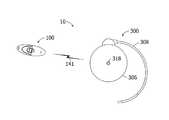
- FIG. 1is a plan view of an ambulatory medical device system in accordance with one embodiment of a present invention.
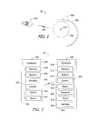
- FIG. 2is a block diagram of the ambulatory medical device system illustrated in FIG. 1 .
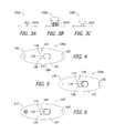
- FIGS. 3A-3Cillustrate alternate user input mechanisms for the remote control of FIG. 1 in the form of a positionable lever, a turnable knob, and a switch, respectively.
- FIG. 4illustrates an embodiment of a remote control that includes first and second user operated controls.
- FIG. 5illustrates an alternate embodiment of a remote control that includes only a single LED.
- FIG. 6illustrates an alternate embodiment of a remote control that includes an audio speaker.
- FIG. 7is a flow chart in accordance with one embodiment of a present invention.
- FIG. 8is a state machine in accordance with one embodiment of a present invention.
- FIGS. 9A and 9Bare timing diagrams showing LED illumination for the “Assign Success” and “Assign Failure” states, respectively, of FIG. 8 .
- FIG. 10is a display lights legend for a remote control device in accordance with one embodiment of the present invention.
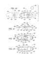
- FIG. 11is a plan view of a remote control in a locked state in accordance with one embodiment of a present invention.
- FIG. 12is partial section view taken along line 12 - 12 in FIG. 11 .
- FIG. 13is a plan view of the remote control illustrated in FIG. 11 in an unlocked state.
- FIG. 14is a side view of the remote control illustrated in FIG. 11 in an unlocked state.
- FIG. 15is a side view of the remote control illustrated in FIG. 11 in an unlocked state and actuated state.
- FIG. 16is a partially exploded view of the remote control illustrated in FIG. 11 .
- FIG. 17is a side, partial section view of the remote control illustrated in FIG. 11 in a locked state.
- FIG. 18is a plan view of the underside of an exemplary housing top member in a locked state.
- FIG. 19is a plan view of an exemplary housing bottom member.
- FIG. 20is a plan view of the remote control illustrated in FIG. 11 in an unlocked state.
- FIG. 21is a plan view of the underside of the housing top member illustrated in FIG. 18 in an unlocked state.
- FIG. 22is a side, partial section view of the remote control illustrated in FIG. 11 in an unlocked state.
- FIG. 23is a side, partial section view of a portion the remote control illustrated in FIG. 11 in an unlocked and actuated state.
- the present remote controlshave application in a wide variety of medical device systems.
- One example of such a systemis an implantable infusion device system and the present inventions are discussed in the context of implantable infusion device systems.
- the present inventionsare not, however, limited to implantable infusion device systems and are instead also applicable to other medical device systems that currently exist, or are yet to be developed.
- the present inventionsare applicable to other ambulatory medical device systems.
- Such systemsinclude, but are not limited to, externally carried infusion pump systems, implantable pacemaker and/or defibrillator systems, implantable neural stimulator systems, and implantable and/or externally carried physiologic sensor systems.
- an implantable infusion device systemis an implantable infusion device system.
- the implantable infusion device systemmay include any one of the remote controls described herein in combination with an implantable infusion device.
- an implantable infusion device system 10includes a remote control 100 and an implantable infusion device 300 .
- the remote control 100includes a battery or other power source 136 , a controller 138 , such as a microprocessor, microcontroller or other control circuitry, memory 139 , an actuator 142 with a movable element, and one or more LEDs 146 (and/or alarm 147 ).
- the memory 139can also be contained within the controller 138 (e.g., within a microcontroller).
- the alarm 147can include one or more of an audio speaker and a vibration device.
- a communication device 140(including an antenna if necessary) is also provided. The communication device 140 establishes a communications link 141 , e.g., a radio frequency (RF) communications link, with the implantable infusion device 300 .
- RFradio frequency
- the communication device 140is a telemetry device that transmits an RF signal at a specified frequency or set of frequencies. In an example implementation, there are five channels.
- the RF signalmay, in some instances, be a carrier signal that carriers bit streams.
- the communication device 140is also configured to receive signals from the implantable infusion device 300 .
- Other exemplary communication devicesinclude oscillating magnetic field communication devices, static magnetic field communication devices, optical communication devices, ultrasound communication devices and direct electrical communication devices.
- the implantable infusion device 300includes a medication reservoir 302 and a pump or other fluid transfer device 304 within a housing 306 .
- the pump 304transfers medication from the reservoir 302 through a catheter 308 to the target region within the body.
- Operation of the implantable infusion device 300is controlled by a controller 310 , such as a microprocessor, microcontroller or other control circuitry, in accordance with instructions stored in memory 312 .
- Poweris provided by a battery or other power source 314 .
- An alarm 316(e.g., an audible alarm such as an audio speaker, and/or a vibration device) may also be provided in order to inform the patient, for example, when the amount of medication in the reservoir 302 is low or when the amount of energy stored in the battery 314 is low.
- a refill port 318which allows the reservoir to be refilled while the implantable infusion device 300 is within the patient, is positioned on the exterior of the housing 306 .
- a communication device 320is also provided.
- the communication device 320is configured to receive signals from, and transmit signals to, the remote control 100 .
- the communication device 320is a telemetry device that transmits and receives RF signals at a specified frequency or set of frequencies.
- the RF (or other) signalmay, in some instances, be a carrier signal that carriers bit streams.
- the remote control 100can include one or more user input mechanisms, as well as different types of user input mechanisms.
- the remote control 100includes a single user operated control (e.g., button 104 ) which is a user input mechanism adapted to be actuated by a user of the remote control 100 to generate a user input.
- the single user operated controlis not limited to pressable buttons.
- remote control 100 a , 100 b , and 100 care instead provided with a positionable lever 104 a , a turnable knob 104 b , and a switch 104 c , respectively.
- a method for communicating between a remote control and an ambulatory medical deviceincludes actuating the single user input mechanism of the remote control to generate a sequence of user inputs recognizable by the remote control as an instruction to generate and transmit to the ambulatory medical device via the communication link a marrying command that assigns the remote control to the ambulatory medical device enabling the ambulatory medical device to respond only to operational commands provided by the remote control.
- the methodfurther includes using a status indicator (e.g., one or more of the LED(s) 146 , the alarm 147 , and the alarm 316 ) to indicate the status of the remote control or the ambulatory device.
- remote control 100 dincludes first and second user operated controls.
- the first user operated controle.g., button 104
- the second user operated controle.g., ON/OFF, power or enable switch 200
- the scope of the present inventionincludes remote controls with a single (i.e., only one) user input mechanism, regardless of the number of user operated controls.
- a method for communicating between a remote control and an ambulatory medical deviceincludes generating by actuating only the single user input mechanism of the remote control a sequence of user inputs recognizable as an instruction to generate and transmit to the ambulatory medical device via the communication link a marrying command that assigns the remote control to the ambulatory medical device enabling the ambulatory medical device to respond only to the operational commands of the remote control.
- the methodfurther includes signaling to the user through user prompts generated by a status indicator when the sequence of user inputs has been received.
- the methodfurther includes actuating the second user operated control of the remote control to enable the remote control to communicate with the ambulatory device via the communication link.
- remote control 100 eincludes only a single LED 146 .
- remote control 100 eincludes alarm 147 , instead of LED(s) 146 .
- both the remote control device and the ambulatory medical devicestore in their respective memories the unique identifying address, number, etc. of the other device.
- Example “marrying” processes described hereinutilize a single user input mechanism of the remote control in a manner distinguishable from other operations such a commanding a bolus or sending a diagnostic signal (pertaining to a diagnostic event). This prevents the inadvertent assigning/reassigning of a new remote control device to an ambulatory medical device.
- a diagnostic eventcan be a breakthough-pain episode experienced by the patient.
- the patientpushes the button on the remote control when he or she is experiencing higher-than-normal pain.
- the physiciancan review the resulting log and use it to adjust the drug delivery program (i.e., background rate).
- a diagnostic eventcan be an episode of patient overmedication.
- the patientpushes the button on the remote control when he or she is feeling the effects of overmedication, such as lethargia. This information can also be used by the physician to adjust the drug delivery program.
- the remote controlcan be used to generate diagnostic signals to track any unintended side effect or patient activity.
- a remote control for use with an ambulatory medical deviceincludes a user input mechanism adapted to be actuated to generate user inputs, a communication device adapted to facilitate a communication link between the remote control and the ambulatory medical device, and a controller adapted to control the communication device in response to the user input mechanism being actuated, and to receive and process the user inputs to determine whether the user inputs represent a sequence authorizing an assignment of the remote control to the ambulatory medical device.
- the remote controlhas only a single user operated control, which user operated control is the user input mechanism.
- the single user operated controlis selected from the group consisting of a pressable button, a switch, a knob, and a lever.
- the remote controlhas at least one other user operated control, in addition to the user input mechanism, wherein the at least one other user operated control is not configured to provide a sequence for marrying the remote control to the ambulatory medical device.
- the remote controlfurther includes a status indicator.
- the controlleris adapted to generate and control the communications device to transmit a command to the ambulatory medical device to generate an audible sound.
- the commandis generated and transmitted after the sequence has been provided.
- the remote controlfurther includes one or more light sources; and the controller is adapted to control the one or more light sources (e.g., two light sources).
- the controlleris adapted to control the one or more light sources to provide a user prompt for an additional user input.
- the remote controlfurther includes an audio speaker; and the controller is adapted to control the audio speaker.
- the controlleris adapted to control the audio speaker to provide a user prompt for an additional user input.
- the remote controlfurther includes a vibration device; and the controller is adapted to control the vibration device.
- the controlleris adapted to control the vibration device to provide a user prompt for an additional user input.
- the remote controlfurther includes a memory device; and the controller is adapted to store in the memory device ambulatory medical device identification information transmitted from the ambulatory medical device to the remote control via the communication link.
- the controlleris adapted to store the ambulatory medical device identification information in the memory device after an assignment confirmation input has been provided via the user input mechanism. In an example embodiment, the controller is adapted to control the communications device to transmit remote control identification information after an assignment confirmation input has been provided via the user input mechanism.
- a medical device systemincludes a remote, the remote having only a single user operated control, which is a single user input mechanism, an ambulatory medical device, and a communication link between the remote and ambulatory medical device.
- the single user operated controlis adapted to be actuated by a user of the remote to generate user inputs; and the remote includes a controller adapted to control the communication link in response to the single user operated control being actuated, and to receive and process the user inputs to determine whether the user inputs represent a sequence authorizing an assignment of the remote to the ambulatory medical device.
- a medical device systemincludes a remote control including first and second user operated controls, the first user operated control being a single user input mechanism adapted to be actuated by a user of the remote control to generate user inputs, an ambulatory medical device, and a communication link between the remote and ambulatory medical device, the communication link being adapted to transmit a sequence of the user inputs generated using only the single user input mechanism to assign the remote control to the ambulatory medical device.
- the remote controlincludes a controller adapted to control the communication link in response to the first user operated control being actuated, and to receive and process the user inputs to determine whether the user inputs represent a sequence authorizing an assignment of the remote control to the ambulatory medical device.
- the remote control 100may be used, for example, to send a “bolus delivery” request or diagnostic signal to the implantable infusion device 300 by way of the communication devices 140 and 320 when a user input mechanism of the remote control 100 is actuated.
- the remote control controller 138may actuate one or more of the LEDs 146 in order to confirm to the patient that the “bolus delivery” request has been transmitted.
- the implantable infusion device controller 310may respond to the receipt of the “bolus delivery” request in a variety of ways. For example, the controller 310 may accept the request, actuate the fluid transfer device 304 , and transmit an “acceptance” signal to the remote control 100 . In response to the “acceptance” signal, the remote control controller 138 may actuate one or more of the LEDs 146 so as to indicate that that the “bolus delivery” request has been accepted.
- the controller 310may, alternatively, deny the “bolus delivery” request because the fluid transfer device 304 is already in the process of transferring medication to the catheter 308 , the patient has already reached the maximum permissible number of bolus deliveries for a particular time period, or there has not been sufficient time since the last delivery of medication.
- a “denial” signalmay also be transmitted from the infusion device 300 to the remote control 100 and, in response, the remote control controller 138 may actuate one or more of the LEDs 146 so as to indicate that the “bolus delivery” request has been denied.
- FIG. 7is a flow chart in accordance with one embodiment of a present invention.
- Step 01provides that the user (e.g., physician, health care professional, patient, etc.): actuate the single user input mechanism of a remote control to generate a sequence of user inputs recognizable by the remote control as an instruction to generate and transmit to an ambulatory medical device via a communication link a marrying command that assigns the remote control to the ambulatory medical device enabling the ambulatory medical device to respond only to operational commands provided by the remote control.
- the term “operational commands”includes both bolus delivery signals as well as diagnostic signals.
- Step 02delivery a predetermined dosage of therapeutic treatment with the ambulatory device by activating the same user input mechanism to generate a signal to the ambulatory device to commence delivering the predetermined dosage of therapeutic treatment
- Step 03generator a second predetermined sequence to provide a diagnostic signal to the ambulatory device using the same user input mechanism
- a method of communicating between a remote control device and an ambulatory deviceincludes marrying a remote control device with an ambulatory device by providing a predetermined sequence of user inputs using a user input mechanism on the remote control device, and after the marrying step is completed, delivering a predetermined dosage of therapeutic treatment with the ambulatory device by activating the same user input mechanism to generate a signal to the ambulatory device to commence delivering the predetermined dosage of therapeutic treatment.
- a method of operating a remote control device and ambulatory deviceincludes generating a first predetermined sequence to marry a remote control device with an ambulatory device by providing a predetermined sequence of user inputs using a user input mechanism on the remote control device, and generating a second predetermined sequence to provide a diagnostic signal to the ambulatory device using the same user input mechanism.
- the methodfurther includes uplinking the diagnostic signal to generate a status indicator concerning diagnostics.
- a method for assigning a remote control to an ambulatory medical deviceincludes generating and transmitting user inputs from a remote control to an ambulatory medical device, and receiving and processing the user inputs to determine whether the user inputs represent a sequence authorizing an assignment of the remote control to the ambulatory medical device.
- the sequencespecifies a predetermined number of user inputs, or a predetermined number and pattern of user inputs.
- the predetermined number of user inputscan be two, three, four, or any other number.
- the methodfurther includes providing a user prompt for an additional user input (e.g., an assignment confirmation input).
- the user promptis generated after the sequence authorizing an assignment has been provided.
- the user promptis generated after a signal generated by the ambulatory medical device is received by the remote control.
- the user promptcan be generated by any of the status indicators on either the remote control device or the ambulatory medical device.
- the user promptis generated by controlling one or more light sources to flash at the remote control.
- the user promptis one or more of an audible sound in the remote control, an audible sound in the ambulatory medical device, a visual indication on the remote control, and a vibration of the remote control.
- the remote controlhas a sound source for producing at least two distinguishable sounds.
- the sequencespecifies a temporal requirement for providing one or more of the user inputs.
- the temporal requirementis a maximum amount of time that the user input mechanism can be actuated in order to provide one or more of the user inputs.
- the temporal requirementis a minimum amount of time that the user input mechanism can be actuated in order to provide one or more of the user inputs.
- the temporal requirementcan be a maximum time interval allowed between two of the user inputs.
- the temporal requirementincludes a maximum amount of time the user input mechanism can be activated in order to provide one or more user inputs, a minimum amount of time that the user input mechanism can be activated in order to provide one or more user inputs, and a maximum time interval allowed between two of the user inputs.
- FIG. 8is a state machine 800 in accordance with one embodiment of a present invention.
- three rapid user inputse.g., button presses
- PRpatient remote
- the state machine 800specifies a maximum amount of time (e.g., 0.2 seconds) the user input mechanism can be activated in order to provide each of the user inputs at states 804 , 806 , and 808 , as well as a maximum time interval allowed (e.g., 0.5 seconds) between the user inputs provided at states 804 , 806 , and 808 .
- two LEDse.g., green and amber
- Thisprovides an indication of the “ready to assign” state to the user.
- an audio speaker and/or vibration devicecan instead (or additionally) be used to provide status indications, user prompts, and the like.
- the useris prompted (as described above) during the “ready to assign” state 810 to provide an additional user input. More specifically, in this example embodiment, the user has 10 seconds to continuously press the button for at least one second, which generates a query for the Implantable Drug Pump (IDP). If the user “times out” by failing to provide the additional input within 10 seconds, or if the user does not continuously provide the additional input for at least one second, he or she is returned to the Idle state 802 . At Assign 1 state 812 , up to three Query Attempts are made (e.g., with a 2 second timeout specified).
- IDPImplantable Drug Pump
- the state machine 800advances to the Assign 2 state 814 where assignment of the PR to the IDP is attempted. At Assign 2 state 814 , up to three Assign Attempts are made (e.g., with a 2 second timeout specified). If there is a successful Assign Response, the state machine 800 advances to the Assign Success state 816 , and the green LED is illuminated solid ( FIG. 9A ). However, if there are three failed Query Attempts or Assign Attempts, the state machine 800 advances to the Assign Failure state 818 , and the amber LED is illuminated at 2 Hz 50% duty cycle ( FIG. 9B ).
- FIG. 10is a display lights legend for a remote control device in accordance with one embodiment of the present invention.
- This legenddemonstrates that the status indicators can be controlled for multiple purposes including, but not limited to, providing indications relating to “marrying” (or attempting to “marry”) a remote control device to an ambulatory device, bolus requests, available battery power.
- a Ready to Assign statusis indicated by alternately illuminating amber and green LEDs.
- LEDs or light sources of any color or combination of colorscan be used, and that the display light patterns can be varied. For example, it may be appropriate to use a greater variety of patterns when only a single LED or other light source is included in the remote control device.
- a remote control device with a single LED, single color of LED, or alarm (audible speaker or vibration device) adapted to provide user prompts and status indicatorsmay be particularly beneficial for the visually impaired or color blind.
- the controller 138is instead adapted to control the alarm 147 (e.g., an audio speaker) to generate sequences of tones which represent a status and/or user prompt.
- the controllercan include voice synthesizer functionality and be adapted to control the audio speaker to generate more human friendly indications (i.e., audible voice reading words or phrases, such as “Ready to Assign”, etc.)
- the exemplary remote control 100includes a housing 102 and a button 104 .
- the housing 102carries a movable button control element 106 with a depressible member 108 that is positioned over the button 104 .
- the remote control 100will generate a signal when the button 104 is pressed and, depending on its position, the button control element 106 will control the operation of the button by either preventing or allowing the button to be pressed.
- the exemplary remote control 100is shown in the locked state, i.e. the state in which the button 104 may not be pressed, in FIGS. 11 and 12 . More specifically, when the movable button control element 106 is in the position illustrated in FIGS. 11 and 12 , the depressible member 108 will be aligned with a barrier 110 ( FIG. 13 ) on the housing 102 .
- the barrier 110which may include abutments 112 , prevents the depressible member 108 on the button control element 106 from being depressed, thereby preventing the button 104 from being pressed.
- the exemplary remote control 100may be adjusted to the unlocked state illustrated in FIGS. 13 and 14 , i.e. the state in which the button 104 may be pressed, by moving the button control element 106 in the direction of arrow A until the depressible member 108 is no longer aligned with the barrier 110 and is instead aligned with a housing aperture 114 that is adjacent to the barrier.
- the housing 102 in the exemplary embodimentincludes a surface 116 that is shaped to receive the user's forefinger and the button control element 106 includes a raised area 118 that combines with the depressible member 108 to form a region that is shaped to receive the user's thumb.
- This configurationallows the user to easily hold the remote control 100 between his or her thumb and forefinger and slide the button control element 106 with the thumb.
- the depressible member 108 and raised area 118also include ridges 120 which prevent the user's thumb from slipping.
- the housing 102 and button control element 106perform the advantageous function of preventing inadvertent communication between the exemplary remote control 100 and the associated medical device by preventing the button 104 from being pressed unless the user has demonstrated his/her intent to press the button. Such intent is demonstrated, in the context of the exemplary remote control 100 , by sliding the button control element 106 from the locked position ( FIGS. 11 and 12 ) to the unlocked position ( FIGS. 13 and 14 ) prior to pressing the button 104 .
- FIGS. 11-14There are a variety of structural configurations that would allow a remote control to move from a locked state to an unlocked state in the manner illustrated in FIGS. 11-14 , and then be actuated in the manner illustrated in FIG. 15 .
- One example of such a configurationis described below with reference to FIGS. 16-23 .
- the exemplary housing 102includes a bottom member 122 and a top member 124 .
- the bottom member 122has a main wall 126 , an outer wall 128 that extends around the perimeter of the main wall, and inner walls 130 and 132 .
- the inner walls 130 and 132define storage regions for a circuit board 134 and a battery 136 .
- the circuit board 134carries a controller 138 , a communication device 140 (including an antenna), an actuator 142 with a movable element 144 , and a pair of LEDs 146 (or other light emitting elements).
- the movable element 144is aligned with the housing aperture 114 and, in the illustrated embodiment, the housing aperture is covered by a resilient cover 148 that keeps dirt and moisture out of the closed interior space within the housing 102 .
- the actuator 142may be, for example, a normally open switch that is biased to the open state and is closed in response to downward (in the illustrated orientation) movement of the movable element 144 , as is discussed in greater detail below with reference to FIG. 23 .
- the exemplary button 104which consists of the actuator 142 and the resilient cover 148 , may be pressed by depressing the depressible member 108 when the remote control 100 is in the unlocked state ( FIGS. 13-15 ). Specifically, the depressible member 108 will press the resilient cover 148 which, in turn, will press the movable element 144 of the actuator 142 and close the switch. In some alternative embodiments, the housing aperture 114 will be uncovered and the depressible member 108 will come into direct contact with the actuator 142 . In either case, the controller 138 will instruct the communication device 140 to transmit a signal when the switch is closed.
- the top member 124 of the exemplary housing 102covers the bottom member 122 , thereby defining a closed interior space, and also includes the housing aperture 114 .
- the top member 124may, for purposes of this description, be divided into a first section 150 that is generally aligned with the button control element 106 , and a second section 152 that is located below the button control element.
- the barrier 110 and housing aperture 114are part of the second section 152 and the barrier is located between the housing aperture and the first section 150 .
- the second section 152includes light apertures 154 that allow light from the LEDs 146 to pass through the housing 102 .
- the button control element 106 in the illustrated embodimentis translucent. As such, light from the LEDs 146 that passes through the light apertures 154 will be visible to the user.
- the top member 124 illustrated in FIGS. 16-18has a main wall 156 that forms the first and second sections 150 and 152 , an outer wall 158 , and inner walls 160 and 162 .
- the outer and inner walls 128 - 132 of the bottom member 122abut the outer and inner walls 158 - 162 of the top member 124 .
- the bottom member 122may also be provided with a plurality of holes (not shown), and the top member 124 may also be provided with a corresponding plurality of posts (not shown) that are configured to be interference fit into the holes to secure the top member to the bottom member.
- the button control elementincludes a main wall 164 and an outer wall 166 .
- the button control element 106is also configured to slide along the second section 152 of the housing top member 124 .
- the button control element 106is provided with a pair of longitudinally extending inner walls 168 that are in close proximity to, as well as parallel to, the two longitudinally extending portions of the top member inner wall 160 .
- the button control element 106also has transversely extending inner walls 170 that are positioned such that they abut transversely ending walls 172 ( FIGS.
- the button control element 106also includes covers 174 ( FIG. 18 ) that extend inwardly from the outer wall 166 .
- the wide portions 176 ( FIG. 16 ) of the top member second section 152slide within the spaces defined by the covers 174 and the button control element main and outer walls 164 and 166 .
- the button control element 106is provided with a pair of guides 178 which slide within a corresponding pair of slots 180 ( FIG. 18 ) that are located within the first section 150 of the housing top member 124 .
- the button control element 106includes a plurality of stop members 181 that engage the curved portion of the inner wall 160 on the housing top member 124 .
- the longitudinally extending portions of the top member inner wall 160 , the movable portion inner walls 168 , the covers 174 , the top member wide portions 176 , the guides 178 and slots 180individually and collectively prevent the movable button control element 106 from sliding in any direction other than along the longitudinal axis of the housing 102 .
- the orientation of the longitudinal axisis the same as the orientation of arrow A in FIG. 13 .
- the guides 178also prevent debris from entering the housing 102 when the button control element 106 is in the unlocked position.
- the covers 174 and the top member wide portion 176also prevent the button control element 106 from being moved upwardly (in the orientation illustrated in FIG. 17 ) and pulled off the housing top member 124 .
- the alignment of the housing first section 150 with the button control element 106prevents a fingernail or object from getting under, and lifting, the depressible member when the remote control 100 is in the locked state.
- the button control element 106is biased to the locked position illustrated in FIGS. 11 , 12 , 17 and 18 . Thus, unless the user is applying force to button control element 106 in the direction of arrow A ( FIG. 13 ), the button control element will remain in the locked position and the depressible member 108 will remain on the barrier 110 .
- the exemplary remote control 100includes a pair of tension springs 186 .
- the tension springs 186may be attached to the button control element 106 and to the housing top member 124 .
- the tension springs 186also help prevent the button control element 106 from being pulled off of the housing 102 .
- the depressible member 108is part of the button control element 106 and rests on the barrier abutments 112 when the exemplary remote control 100 is in the locked state. More specifically, in the illustrated embodiment, the depressible member 108 is secured to the remainder of the button control element 106 by a living hinge 188 ( FIG. 17 ) and includes a pair of downwardly extending protrusions 190 that rest on the barrier abutments 112 .
- the living hinge 188allows the depressible member 108 to pivot from the position illustrated in FIG. 14 to the position illustrated in FIG. 15 .
- the living hinge 188also biases the depressible member 108 to the position illustrated in FIG. 14 .
- the living hinge biasprovides an additional level of safety in that simply overcoming the biasing force on the button control element 106 and moving the button control element to the unlocked position will not, in and of itself, result in the button 104 being pressed and a signal being generated. The user must also press the depressible member 108 while maintaining the button control element 106 in the unlocked position.
- the exemplary remote control 100is shown in the unlocked and actuated state (i.e. with the button 104 pressed) in FIG. 23 .
- the depressible member 108is aligned with the aperture 114 and pivoted about the living hinge 188 into contact with the resilient cover 148 .
- the resilient cover 148is collapses and presses the movable element 144 on the actuator 142 , thereby causing the remote control 100 to generate a signal.
- the exemplary housing 102is also provided with an opening 192 that allows the remote control 100 to be secured to, for example, a band of material and worn like a necklace or to a connector ring that facilitates connection to a key chain or a belt loop.
- the housing top and bottom members 122 and 124may respectively include sealing walls 194 and 196 ( FIGS. 18 and 19 ) that contact one and other and prevent dirt and moisture from entering the housing 102 by way of the opening 192 .
- the exemplary remote control 100may be sized such that it can be conveniently held between the thumb and forefinger and/or placed in the user's pocket.
- the remote control 100is about 7.5 cm long, 3.5 cm wide and, at its thickest region, about 1.5 cm thick.
Landscapes
- Engineering & Computer Science (AREA)
- Health & Medical Sciences (AREA)
- Public Health (AREA)
- Biomedical Technology (AREA)
- General Health & Medical Sciences (AREA)
- General Physics & Mathematics (AREA)
- Physics & Mathematics (AREA)
- Computer Networks & Wireless Communication (AREA)
- Primary Health Care (AREA)
- Medical Informatics (AREA)
- Epidemiology (AREA)
- Radiology & Medical Imaging (AREA)
- Veterinary Medicine (AREA)
- Animal Behavior & Ethology (AREA)
- Life Sciences & Earth Sciences (AREA)
- Nuclear Medicine, Radiotherapy & Molecular Imaging (AREA)
- Human Computer Interaction (AREA)
- Business, Economics & Management (AREA)
- General Business, Economics & Management (AREA)
- Chemical & Material Sciences (AREA)
- Bioinformatics & Cheminformatics (AREA)
- Medicinal Chemistry (AREA)
- Infusion, Injection, And Reservoir Apparatuses (AREA)
- Selective Calling Equipment (AREA)
Abstract
Description
Claims (20)
Priority Applications (2)
| Application Number | Priority Date | Filing Date | Title |
|---|---|---|---|
| US11/932,856US9135810B2 (en) | 2006-11-28 | 2007-10-31 | Method, apparatus and system for assigning remote control device to ambulatory medical device |
| PCT/US2007/085592WO2008067286A2 (en) | 2006-11-28 | 2007-11-27 | Method, apparatus and system for assigning remote control device to ambulatory medical device |
Applications Claiming Priority (2)
| Application Number | Priority Date | Filing Date | Title |
|---|---|---|---|
| US86758006P | 2006-11-28 | 2006-11-28 | |
| US11/932,856US9135810B2 (en) | 2006-11-28 | 2007-10-31 | Method, apparatus and system for assigning remote control device to ambulatory medical device |
Publications (2)
| Publication Number | Publication Date |
|---|---|
| US20080132973A1 US20080132973A1 (en) | 2008-06-05 |
| US9135810B2true US9135810B2 (en) | 2015-09-15 |
Family
ID=39262557
Family Applications (1)
| Application Number | Title | Priority Date | Filing Date |
|---|---|---|---|
| US11/932,856Active2033-02-27US9135810B2 (en) | 2006-11-28 | 2007-10-31 | Method, apparatus and system for assigning remote control device to ambulatory medical device |
Country Status (2)
| Country | Link |
|---|---|
| US (1) | US9135810B2 (en) |
| WO (1) | WO2008067286A2 (en) |
Cited By (2)
| Publication number | Priority date | Publication date | Assignee | Title |
|---|---|---|---|---|
| US20150051444A1 (en)* | 2009-11-15 | 2015-02-19 | Matthew Zane Schwartz | Drug delivery system for treating erectile dysfunction |
| WO2021081354A1 (en) | 2019-10-23 | 2021-04-29 | The Alfred E. Mann Foundation For Scientific Research | Implantable infusion devices with closed loop sensing and associated methods |
Families Citing this family (25)
| Publication number | Priority date | Publication date | Assignee | Title |
|---|---|---|---|---|
| US20090043365A1 (en) | 2005-07-18 | 2009-02-12 | Kolis Scientific, Inc. | Methods, apparatuses, and systems for reducing intraocular pressure as a means of preventing or treating open-angle glaucoma |
| US20070060988A1 (en) | 2005-07-18 | 2007-03-15 | Grenon Stephen M | Melting meibomian gland obstructions |
| WO2013003594A2 (en) | 2011-06-28 | 2013-01-03 | Tearscience, Inc. | Methods and systems for treating meibomian gland dysfunction using radio-frequency energy |
| US7981146B2 (en) | 2006-05-15 | 2011-07-19 | Tearscience Inc. | Inner eyelid treatment for treating meibomian gland dysfunction |
| US20070016256A1 (en) | 2005-07-18 | 2007-01-18 | Korb Donald R | Method and apparatus for treating gland dysfunction |
| US8950405B2 (en) | 2006-05-15 | 2015-02-10 | Tearscience, Inc. | Treatment of obstructive disorders of the eye or eyelid |
| US20080114423A1 (en) | 2006-05-15 | 2008-05-15 | Grenon Stephen M | Apparatus for inner eyelid treatment of meibomian gland dysfunction |
| US7981145B2 (en) | 2005-07-18 | 2011-07-19 | Tearscience Inc. | Treatment of meibomian glands |
| US7981095B2 (en) | 2005-07-18 | 2011-07-19 | Tearscience, Inc. | Methods for treating meibomian gland dysfunction employing fluid jet |
| US8007524B2 (en) | 2006-05-15 | 2011-08-30 | Tearscience, Inc. | Heat treatment and heat loss reduction for treating meibomian gland dysfunction |
| US8137390B2 (en)* | 2006-05-15 | 2012-03-20 | Tearscience, Inc. | System for providing heat treatment and heat loss reduction for treating meibomian gland dysfunction |
| US7981147B2 (en) | 2006-05-15 | 2011-07-19 | Tearscience, Inc. | Outer eyelid heat and pressure treatment for treating meibomian gland dysfunction |
| US7976573B2 (en) | 2006-05-15 | 2011-07-12 | Tearscience, Inc. | Inner eyelid heat and pressure treatment for treating meibomian gland dysfunction |
| US9314369B2 (en) | 2006-05-15 | 2016-04-19 | Tearscience, Inc. | System for inner eyelid treatment of meibomian gland dysfunction |
| US8128673B2 (en) | 2006-05-15 | 2012-03-06 | Tearscience, Inc. | System for inner eyelid heat and pressure treatment for treating meibomian gland dysfunction |
| US8128674B2 (en) | 2006-05-15 | 2012-03-06 | Tearscience, Inc. | System for outer eyelid heat and pressure treatment for treating meibomian gland dysfunction |
| US20080243078A1 (en)* | 2007-04-02 | 2008-10-02 | Pacific Hosptial Supply Co., Ltd. | Single control button type automatic infusion pump operation method |
| USD638128S1 (en) | 2009-10-06 | 2011-05-17 | Tearscience, Inc. | Ocular device design |
| US10842670B2 (en) | 2012-08-22 | 2020-11-24 | Johnson & Johnson Vision Care, Inc. | Apparatuses and methods for diagnosing and/or treating lipid transport deficiency in ocular tear films, and related components and devices |
| JP6051691B2 (en)* | 2012-08-31 | 2016-12-27 | 株式会社リコー | Device cooperation program, device cooperation system, device cooperation method, and portable terminal |
| EP3744391B1 (en) | 2013-04-30 | 2023-03-01 | Alcon Inc. | Systems for the treatment of eye conditions |
| US9763827B2 (en) | 2013-04-30 | 2017-09-19 | Tear Film Innovations, Inc. | Systems and methods for the treatment of eye conditions |
| KR102504798B1 (en)* | 2015-01-20 | 2023-03-02 | 노파르티스 아게 | Application unlock using a connected physical device and transfer of data therebetween |
| US10974063B2 (en) | 2016-06-30 | 2021-04-13 | Alcon Inc. | Light therapy for eyelash growth |
| JP7486353B2 (en)* | 2020-06-05 | 2024-05-17 | 日本光電工業株式会社 | Automatic external defibrillator and method for notifying abnormality of automatic external defibrillator |
Citations (50)
| Publication number | Priority date | Publication date | Assignee | Title |
|---|---|---|---|---|
| US4855746A (en) | 1984-07-30 | 1989-08-08 | Zenith Electronics Corporation | Multiple device remote control transmitter |
| US5069668A (en) | 1990-07-12 | 1991-12-03 | Boydman Scott A | Patient controlled analgesia system |
| US5232448A (en) | 1989-12-05 | 1993-08-03 | Prime Medical Products | Patient-controlled analgesia device |
| US5338157A (en) | 1992-09-09 | 1994-08-16 | Pharmacia Deltec, Inc. | Systems and methods for communicating with ambulatory medical devices such as drug delivery devices |
| US6077055A (en) | 1998-12-03 | 2000-06-20 | Sims Deltec, Inc. | Pump system including cassette sensor and occlusion sensor |
| US6106576A (en) | 1994-07-19 | 2000-08-22 | Maxwell Products, Inc. | Adjustable massage bed assembly with handheld control unit having automatic stop safety feature |
| US6269340B1 (en) | 1992-10-15 | 2001-07-31 | The General Hospital | Infusion pump with an electronically loadable drug library and a user interface for loading the library |
| US20010049673A1 (en) | 2000-03-24 | 2001-12-06 | Bridge Medical, Inc. | Method and apparatus for displaying medication information |
| US20010056358A1 (en) | 2000-03-24 | 2001-12-27 | Bridge Medical, Inc., | Method and apparatus for providing medication administration warnings |
| US6381496B1 (en) | 1999-10-01 | 2002-04-30 | Advanced Bionics Corporation | Parameter context switching for an implanted device |
| US20020058906A1 (en) | 2000-01-21 | 2002-05-16 | Lebel Ronald J. | Microprocessor controlled ambulatory medical apparatus with hand held communication device |
| US20020126036A1 (en) | 2000-12-21 | 2002-09-12 | Flaherty J. Christopher | Medical apparatus remote control and method |
| US20020138155A1 (en) | 2001-03-26 | 2002-09-26 | Bristol Guy Scott | Implantable medical device management system |
| US20020143580A1 (en) | 2001-03-26 | 2002-10-03 | Bristol Guy Scott | Implantable therapeutic substance infusion device configuration system |
| US20020193679A1 (en) | 1998-04-29 | 2002-12-19 | Medtronic Minimed, Inc. | Communication station and software for interfacing with an infusion pump, analyte monitor, analyte meter, or the like |
| WO2003026726A1 (en) | 2001-09-26 | 2003-04-03 | Novo Nordisk A/S | Modular drug delivery system |
| US20030163088A1 (en) | 2002-02-28 | 2003-08-28 | Blomquist Michael L. | Programmable medical infusion pump |
| US20030163789A1 (en) | 2002-02-28 | 2003-08-28 | Blomquist Michael L. | Programmable medical infusion pump displaying a banner |
| US20030181852A1 (en) | 1998-08-18 | 2003-09-25 | Medtronic Minimed, Inc. | External infusion device with remote programming, bolus estimator and/or vibration alarm capabilities |
| US6687547B2 (en) | 1999-09-14 | 2004-02-03 | Medtronic, Inc. | Method and apparatus for communicating with an implantable medical device with DTMF tones |
| US20040049245A1 (en)* | 2002-09-09 | 2004-03-11 | Volker Gass | Autonomous patch for communication with an implantable device, and medical kit for using said patch |
| WO2004028596A1 (en) | 2002-09-30 | 2004-04-08 | Novo Nordisk A/S | Indicating device with estimating feature |
| US20040158193A1 (en) | 1999-02-10 | 2004-08-12 | Baxter International Inc. | Medical apparatus using selective graphical interface |
| US20040172301A1 (en) | 2002-04-30 | 2004-09-02 | Mihai Dan M. | Remote multi-purpose user interface for a healthcare system |
| US6796956B2 (en) | 1999-04-30 | 2004-09-28 | Medtronic, Inc. | Method and apparatus to control drug therapy dosages in an implantable pump |
| US20040249477A1 (en) | 2003-04-15 | 2004-12-09 | Yves Blanpain | Operating method for a command transmitter |
| US20050012594A1 (en) | 2003-07-17 | 2005-01-20 | Youngtack Shim | Key assemblies and methods |
| US6880564B2 (en) | 2002-09-20 | 2005-04-19 | Advanced Neuromodulation Systems, Inc. | Dosage control apparatus |
| US20050143864A1 (en) | 2002-02-28 | 2005-06-30 | Blomquist Michael L. | Programmable insulin pump |
| US20050154537A1 (en) | 2003-12-12 | 2005-07-14 | Kutzko John D. | Methods, program products, and systems for single and multi-agent dosing and other related methods |
| US20050177096A1 (en) | 2003-12-05 | 2005-08-11 | Bollish Stephen J. | Patient-controlled analgesia with patient monitoring system and method |
| EP1585080A2 (en) | 2004-03-25 | 2005-10-12 | Christian Genter | Radio switching device and method for controlling and/or programming of a radio switching device |
| US20050251228A1 (en)* | 2003-06-27 | 2005-11-10 | Hamel Andrew J | System for remotely controlling two or more medical devices |
| US7043305B2 (en) | 2002-03-06 | 2006-05-09 | Cardiac Pacemakers, Inc. | Method and apparatus for establishing context among events and optimizing implanted medical device performance |
| US20060100907A1 (en) | 2003-10-07 | 2006-05-11 | Holland Geoffrey N | Medication management system |
| US7054782B2 (en) | 2000-12-29 | 2006-05-30 | Medtronic, Inc. | Non-conformance monitoring and control techniques for an implantable medical device |
| US7060031B2 (en) | 1999-12-17 | 2006-06-13 | Medtronic, Inc. | Method and apparatus for remotely programming implantable medical devices |
| US20060129433A1 (en) | 2004-12-10 | 2006-06-15 | Phanesh Koneru | Method and system for delivering high risk medical therapies |
| US20060149416A1 (en) | 2004-12-03 | 2006-07-06 | Saudi Arabian Oil Company | System and software of enhanced pharmacy services and related methods |
| US20060229557A1 (en) | 2005-04-11 | 2006-10-12 | Fathallah Marwan A | User interface improvements for medical devices |
| US20060229551A1 (en) | 2005-02-11 | 2006-10-12 | Martinez John D | Identification system and method for medication management |
| US20060235472A1 (en) | 2004-07-20 | 2006-10-19 | Medtronic, Inc. | Therapy programming guidance based on stored programming history |
| US20060244627A1 (en) | 2003-08-11 | 2006-11-02 | Robert Kagermeier | Radio operating system and method for operating a radio system |
| US20060265140A1 (en) | 2000-12-29 | 2006-11-23 | Medtronic, Inc. | Therapy management techniques for an implantable medical device |
| US20070118405A1 (en) | 2003-04-18 | 2007-05-24 | Insulet Corporation | User Interface For Infusion Pump Remote Controller And Method Of Using The Same |
| US20080033402A1 (en) | 2006-08-03 | 2008-02-07 | Blomquist Michael L | Interface for medical infusion pump |
| US20090043290A1 (en) | 2007-08-09 | 2009-02-12 | Daniel Hernandez Villegas | Drug Delivery Safety System |
| US20090043291A1 (en) | 1999-04-30 | 2009-02-12 | Medtronic Minimed, Inc. | Closed Loop Medicament Pump |
| US20090143580A1 (en) | 2005-09-27 | 2009-06-04 | Mcarthur Silvia Gatti | SUBSTITUTED PYRAZOLO [1,5-a] PYRIMIDINES AS METABOTROPIC GLUTAMATE ANTAGONISTS |
| US7551078B2 (en) | 2006-05-08 | 2009-06-23 | Ihc Intellectual Asset Management, Llc | Device alert system and method |
- 2007
- 2007-10-31USUS11/932,856patent/US9135810B2/enactiveActive
- 2007-11-27WOPCT/US2007/085592patent/WO2008067286A2/enactiveApplication Filing
Patent Citations (62)
| Publication number | Priority date | Publication date | Assignee | Title |
|---|---|---|---|---|
| US4855746A (en) | 1984-07-30 | 1989-08-08 | Zenith Electronics Corporation | Multiple device remote control transmitter |
| US5232448A (en) | 1989-12-05 | 1993-08-03 | Prime Medical Products | Patient-controlled analgesia device |
| US5069668A (en) | 1990-07-12 | 1991-12-03 | Boydman Scott A | Patient controlled analgesia system |
| US5338157A (en) | 1992-09-09 | 1994-08-16 | Pharmacia Deltec, Inc. | Systems and methods for communicating with ambulatory medical devices such as drug delivery devices |
| US5338157B1 (en) | 1992-09-09 | 1999-11-02 | Sims Deltec Inc | Systems and methods for communicating with ambulat |
| US6269340B1 (en) | 1992-10-15 | 2001-07-31 | The General Hospital | Infusion pump with an electronically loadable drug library and a user interface for loading the library |
| US7471994B2 (en) | 1992-10-15 | 2008-12-30 | The General Hospital Corporation | Infusion pump with an electronically loadable drug library and label reader |
| US6106576A (en) | 1994-07-19 | 2000-08-22 | Maxwell Products, Inc. | Adjustable massage bed assembly with handheld control unit having automatic stop safety feature |
| US20020193679A1 (en) | 1998-04-29 | 2002-12-19 | Medtronic Minimed, Inc. | Communication station and software for interfacing with an infusion pump, analyte monitor, analyte meter, or the like |
| US20030181852A1 (en) | 1998-08-18 | 2003-09-25 | Medtronic Minimed, Inc. | External infusion device with remote programming, bolus estimator and/or vibration alarm capabilities |
| US6077055A (en) | 1998-12-03 | 2000-06-20 | Sims Deltec, Inc. | Pump system including cassette sensor and occlusion sensor |
| US20040158193A1 (en) | 1999-02-10 | 2004-08-12 | Baxter International Inc. | Medical apparatus using selective graphical interface |
| US6796956B2 (en) | 1999-04-30 | 2004-09-28 | Medtronic, Inc. | Method and apparatus to control drug therapy dosages in an implantable pump |
| US20090043291A1 (en) | 1999-04-30 | 2009-02-12 | Medtronic Minimed, Inc. | Closed Loop Medicament Pump |
| US6687547B2 (en) | 1999-09-14 | 2004-02-03 | Medtronic, Inc. | Method and apparatus for communicating with an implantable medical device with DTMF tones |
| US6381496B1 (en) | 1999-10-01 | 2002-04-30 | Advanced Bionics Corporation | Parameter context switching for an implanted device |
| US7060031B2 (en) | 1999-12-17 | 2006-06-13 | Medtronic, Inc. | Method and apparatus for remotely programming implantable medical devices |
| US6562001B2 (en) | 2000-01-21 | 2003-05-13 | Medtronic Minimed, Inc. | Microprocessor controlled ambulatory medical apparatus with hand held communication device |
| US6571128B2 (en) | 2000-01-21 | 2003-05-27 | Medtronic Minimed, Inc. | Microprocessor controlled ambulatory medical apparatus with hand held communication device |
| US20060173444A1 (en) | 2000-01-21 | 2006-08-03 | Medtronic, Inc. | Ambulatory medical apparatus with hand held communication device |
| US6427088B1 (en) | 2000-01-21 | 2002-07-30 | Medtronic Minimed, Inc. | Ambulatory medical apparatus and method using telemetry system with predefined reception listening periods |
| US20020058906A1 (en) | 2000-01-21 | 2002-05-16 | Lebel Ronald J. | Microprocessor controlled ambulatory medical apparatus with hand held communication device |
| US20040193090A1 (en) | 2000-01-21 | 2004-09-30 | Medtronic Minimed, Inc. | Ambulatory medical apparatus with handheld communication device |
| US6694334B2 (en) | 2000-03-24 | 2004-02-17 | Bridge Medical, Inc. | Method and apparatus for displaying medication information |
| US20010056358A1 (en) | 2000-03-24 | 2001-12-27 | Bridge Medical, Inc., | Method and apparatus for providing medication administration warnings |
| US20010049673A1 (en) | 2000-03-24 | 2001-12-06 | Bridge Medical, Inc. | Method and apparatus for displaying medication information |
| US20020126036A1 (en) | 2000-12-21 | 2002-09-12 | Flaherty J. Christopher | Medical apparatus remote control and method |
| US6768425B2 (en) | 2000-12-21 | 2004-07-27 | Insulet Corporation | Medical apparatus remote control and method |
| US20060265140A1 (en) | 2000-12-29 | 2006-11-23 | Medtronic, Inc. | Therapy management techniques for an implantable medical device |
| US7054782B2 (en) | 2000-12-29 | 2006-05-30 | Medtronic, Inc. | Non-conformance monitoring and control techniques for an implantable medical device |
| US20020138155A1 (en) | 2001-03-26 | 2002-09-26 | Bristol Guy Scott | Implantable medical device management system |
| US20020143580A1 (en) | 2001-03-26 | 2002-10-03 | Bristol Guy Scott | Implantable therapeutic substance infusion device configuration system |
| US7072725B2 (en) | 2001-03-26 | 2006-07-04 | Medtronic, Inc. | Implantable therapeutic substance infusion device configuration system |
| WO2003026726A1 (en) | 2001-09-26 | 2003-04-03 | Novo Nordisk A/S | Modular drug delivery system |
| US20030163088A1 (en) | 2002-02-28 | 2003-08-28 | Blomquist Michael L. | Programmable medical infusion pump |
| US20030163789A1 (en) | 2002-02-28 | 2003-08-28 | Blomquist Michael L. | Programmable medical infusion pump displaying a banner |
| US20050143864A1 (en) | 2002-02-28 | 2005-06-30 | Blomquist Michael L. | Programmable insulin pump |
| US7043305B2 (en) | 2002-03-06 | 2006-05-09 | Cardiac Pacemakers, Inc. | Method and apparatus for establishing context among events and optimizing implanted medical device performance |
| US20040172301A1 (en) | 2002-04-30 | 2004-09-02 | Mihai Dan M. | Remote multi-purpose user interface for a healthcare system |
| US20040049245A1 (en)* | 2002-09-09 | 2004-03-11 | Volker Gass | Autonomous patch for communication with an implantable device, and medical kit for using said patch |
| US6880564B2 (en) | 2002-09-20 | 2005-04-19 | Advanced Neuromodulation Systems, Inc. | Dosage control apparatus |
| US6957655B2 (en) | 2002-09-20 | 2005-10-25 | Advanced Neuromodulation Systems, Inc. | Apparatus for dosage control |
| WO2004028596A1 (en) | 2002-09-30 | 2004-04-08 | Novo Nordisk A/S | Indicating device with estimating feature |
| US20040249477A1 (en) | 2003-04-15 | 2004-12-09 | Yves Blanpain | Operating method for a command transmitter |
| US20070118405A1 (en) | 2003-04-18 | 2007-05-24 | Insulet Corporation | User Interface For Infusion Pump Remote Controller And Method Of Using The Same |
| US20050251228A1 (en)* | 2003-06-27 | 2005-11-10 | Hamel Andrew J | System for remotely controlling two or more medical devices |
| US20050012594A1 (en) | 2003-07-17 | 2005-01-20 | Youngtack Shim | Key assemblies and methods |
| US20060244627A1 (en) | 2003-08-11 | 2006-11-02 | Robert Kagermeier | Radio operating system and method for operating a radio system |
| US20060100907A1 (en) | 2003-10-07 | 2006-05-11 | Holland Geoffrey N | Medication management system |
| US20050177096A1 (en) | 2003-12-05 | 2005-08-11 | Bollish Stephen J. | Patient-controlled analgesia with patient monitoring system and method |
| US20050154537A1 (en) | 2003-12-12 | 2005-07-14 | Kutzko John D. | Methods, program products, and systems for single and multi-agent dosing and other related methods |
| EP1585080A2 (en) | 2004-03-25 | 2005-10-12 | Christian Genter | Radio switching device and method for controlling and/or programming of a radio switching device |
| US20060235472A1 (en) | 2004-07-20 | 2006-10-19 | Medtronic, Inc. | Therapy programming guidance based on stored programming history |
| US20060149416A1 (en) | 2004-12-03 | 2006-07-06 | Saudi Arabian Oil Company | System and software of enhanced pharmacy services and related methods |
| US20060129433A1 (en) | 2004-12-10 | 2006-06-15 | Phanesh Koneru | Method and system for delivering high risk medical therapies |
| US20060229551A1 (en) | 2005-02-11 | 2006-10-12 | Martinez John D | Identification system and method for medication management |
| US20060229557A1 (en) | 2005-04-11 | 2006-10-12 | Fathallah Marwan A | User interface improvements for medical devices |
| US7945452B2 (en) | 2005-04-11 | 2011-05-17 | Hospira, Inc. | User interface improvements for medical devices |
| US20090143580A1 (en) | 2005-09-27 | 2009-06-04 | Mcarthur Silvia Gatti | SUBSTITUTED PYRAZOLO [1,5-a] PYRIMIDINES AS METABOTROPIC GLUTAMATE ANTAGONISTS |
| US7551078B2 (en) | 2006-05-08 | 2009-06-23 | Ihc Intellectual Asset Management, Llc | Device alert system and method |
| US20080033402A1 (en) | 2006-08-03 | 2008-02-07 | Blomquist Michael L | Interface for medical infusion pump |
| US20090043290A1 (en) | 2007-08-09 | 2009-02-12 | Daniel Hernandez Villegas | Drug Delivery Safety System |
Non-Patent Citations (1)
| Title |
|---|
| U.S. Appl. No. 11/836,709: Final Rejection, Apr. 26, 2012. |
Cited By (2)
| Publication number | Priority date | Publication date | Assignee | Title |
|---|---|---|---|---|
| US20150051444A1 (en)* | 2009-11-15 | 2015-02-19 | Matthew Zane Schwartz | Drug delivery system for treating erectile dysfunction |
| WO2021081354A1 (en) | 2019-10-23 | 2021-04-29 | The Alfred E. Mann Foundation For Scientific Research | Implantable infusion devices with closed loop sensing and associated methods |
Also Published As
| Publication number | Publication date |
|---|---|
| WO2008067286A3 (en) | 2008-10-02 |
| WO2008067286A2 (en) | 2008-06-05 |
| US20080132973A1 (en) | 2008-06-05 |
Similar Documents
| Publication | Publication Date | Title |
|---|---|---|
| US9135810B2 (en) | Method, apparatus and system for assigning remote control device to ambulatory medical device | |
| US9761128B2 (en) | Remote controls configured to prevent unintended signal transmission and ambulatory medical systems including the same | |
| US20210252301A1 (en) | Shapeable Light Therapy Device and Method | |
| US10946182B2 (en) | Subcutaneous vein access port and medicine injection device having the same | |
| US6934220B1 (en) | Portable programmable medical alert device | |
| US9649439B2 (en) | Systems and methods for facilitating patient-based adjustment of drug infusion | |
| US8352042B2 (en) | Remote controls and ambulatory medical systems including the same | |
| US8831735B2 (en) | Methods and systems for semi-automatic adjustment of medical monitoring and treatment | |
| CN101112630B (en) | Drug delivery systems | |
| US10064992B2 (en) | Disposable tubeless fluid delivery system | |
| US20080140163A1 (en) | Telemetry device for a medical device programmer | |
| US12329939B2 (en) | Devices for reconstituting and delivering lyophilized drugs | |
| EP2300100B1 (en) | Indication of coupling between medical devices | |
| US20040230246A1 (en) | Patient controlled therapy management and diagnostic device with human factors interface | |
| EP2044973A1 (en) | Light-emitting diode (LED) light therapy device | |
| CN101048195A (en) | Method and apparatus for providing safe long-range telemetry with implantable medical devices | |
| EP2044974A1 (en) | Light-emitting diode (LED) light therapy device | |
| CN110090362A (en) | A kind of weak laser diabetes physical therapy insole | |
| WO2008067325A2 (en) | Remote controls and ambulatory medical systems including the same | |
| KR102520514B1 (en) | A heated knee light irradiation device using big data and artificial intelligence, warm knee light irradiation system and its control method | |
| KR20220093977A (en) | About taking medicine automatic alarm apparatus | |
| WO2022176433A1 (en) | Medical device and light-quantity adjusting device | |
| KR102168759B1 (en) | Unit for injecting medicinal fluid | |
| KR0130591B1 (en) | Apparatus for introducing hand acupuncture needle | |
| KR101557971B1 (en) | Pad with low frequency generator |
Legal Events
| Date | Code | Title | Description |
|---|---|---|---|
| AS | Assignment | Owner name:ADVANCED BIONICS CORPORATION, CALIFORNIA Free format text:ASSIGNMENT OF ASSIGNORS INTEREST;ASSIGNORS:GIBSON, SCOTT R.;LORD, PETER CARL;NEWBILL, JON DOUGLAS;AND OTHERS;SIGNING DATES FROM 20071108 TO 20071113;REEL/FRAME:020160/0930 Owner name:ADVANCED BIONICS CORPORATION, CALIFORNIA Free format text:ASSIGNMENT OF ASSIGNORS INTEREST;ASSIGNORS:GIBSON, SCOTT R.;LORD, PETER CARL;NEWBILL, JON DOUGLAS;AND OTHERS;REEL/FRAME:020160/0930;SIGNING DATES FROM 20071108 TO 20071113 | |
| AS | Assignment | Owner name:INFUSION SYSTEMS, LLC, CALIFORNIA Free format text:ASSIGNMENT OF ASSIGNORS INTEREST;ASSIGNOR:BOSTON SCIENTIFIC NEUROMODULATION CORPORATION;REEL/FRAME:020329/0853 Effective date:20080107 | |
| AS | Assignment | Owner name:BOSTON SCIENTIFIC NEUROMODULATION CORPORATION, CAL Free format text:CHANGE OF NAME;ASSIGNOR:ADVANCED BIONICS CORPORATION;REEL/FRAME:020796/0264 Effective date:20071116 | |
| AS | Assignment | Owner name:ALFRED E. MANN FOUNDATION FOR SCIENTIFIC RESEARCH, Free format text:ASSIGNMENT OF ASSIGNORS INTEREST;ASSIGNOR:INFUSION SYSTEMS, LLC;REEL/FRAME:032675/0461 Effective date:20091229 | |
| AS | Assignment | Owner name:ALFRED E. MANN FOUNDATION FOR SCIENTIFIC RESEARCH, Free format text:SECURITY INTEREST;ASSIGNOR:MEDALLION THERAPEUTICS, INC.;REEL/FRAME:032815/0188 Effective date:20140331 | |
| AS | Assignment | Owner name:ALFRED E. MANN FOUNDATION FOR SCIENTIFIC RESEARCH, Free format text:CORRECTIVE ASSIGNMENT TO CORRECT THE SCHEDULE WHICH REFLECTED PATENT NUMBER AS 8,327,041 AND SHOULD HAVE BEEN REFLECTED AS 8,372,041. PREVIOUSLY RECORDED ON REEL 032815 FRAME 0188. ASSIGNOR(S) HEREBY CONFIRMS THE SECURITY INTEREST;ASSIGNOR:MEDALLION THERAPEUTICS, INC.;REEL/FRAME:032827/0478 Effective date:20140331 | |
| AS | Assignment | Owner name:MEDALLION THERAPEUTICS, INC., CALIFORNIA Free format text:ASSIGNMENT OF ASSIGNORS INTEREST;ASSIGNOR:ALFRED E. MANN FOUNDATION FOR SCIENTIFIC RESEARCH;REEL/FRAME:032892/0067 Effective date:20140331 | |
| STCF | Information on status: patent grant | Free format text:PATENTED CASE | |
| MAFP | Maintenance fee payment | Free format text:PAYMENT OF MAINTENANCE FEE, 4TH YR, SMALL ENTITY (ORIGINAL EVENT CODE: M2551); ENTITY STATUS OF PATENT OWNER: SMALL ENTITY Year of fee payment:4 | |
| AS | Assignment | Owner name:THE ALFRED E. MANN FOUNDATION FOR SCIENTIFIC RESEA Free format text:ASSIGNMENT OF ASSIGNORS INTEREST;ASSIGNOR:MEDALLION THERAPEUTICS, INC.;REEL/FRAME:051287/0120 Effective date:20191210 Owner name:THE ALFRED E. MANN FOUNDATION FOR SCIENTIFIC RESEARCH, CALIFORNIA Free format text:ASSIGNMENT OF ASSIGNORS INTEREST;ASSIGNOR:MEDALLION THERAPEUTICS, INC.;REEL/FRAME:051287/0120 Effective date:20191210 | |
| AS | Assignment | Owner name:MEDTRONIC MINIMED, INC., MINNESOTA Free format text:ASSIGNMENT OF ASSIGNORS INTEREST;ASSIGNOR:THE ALFRED E. MANN FOUNDATION FOR SCIENTIFIC RESEARCH;REEL/FRAME:057962/0741 Effective date:20210706 | |
| FEPP | Fee payment procedure | Free format text:ENTITY STATUS SET TO UNDISCOUNTED (ORIGINAL EVENT CODE: BIG.); ENTITY STATUS OF PATENT OWNER: LARGE ENTITY | |
| MAFP | Maintenance fee payment | Free format text:PAYMENT OF MAINTENANCE FEE, 8TH YEAR, LARGE ENTITY (ORIGINAL EVENT CODE: M1552); ENTITY STATUS OF PATENT OWNER: LARGE ENTITY Year of fee payment:8 | |
| AS | Assignment | Owner name:MEDTRONIC MINIMED, INC., CALIFORNIA Free format text:RELEASE BY SECURED PARTY;ASSIGNOR:THE ALFRED E. MANN FOUNDATION FOR SCIENTIFIC RESEARCH;REEL/FRAME:071698/0639 Effective date:20250523 |