US9132261B2 - In vivo filter assembly - Google Patents
In vivo filter assemblyDownload PDFInfo
- Publication number
- US9132261B2 US9132261B2US13/237,977US201113237977AUS9132261B2US 9132261 B2US9132261 B2US 9132261B2US 201113237977 AUS201113237977 AUS 201113237977AUS 9132261 B2US9132261 B2US 9132261B2
- Authority
- US
- United States
- Prior art keywords
- filter
- cord
- balloon
- assembly according
- lumen
- Prior art date
- Legal status (The legal status is an assumption and is not a legal conclusion. Google has not performed a legal analysis and makes no representation as to the accuracy of the status listed.)
- Active, expires
Links
Images


Classifications
- A—HUMAN NECESSITIES
- A61—MEDICAL OR VETERINARY SCIENCE; HYGIENE
- A61M—DEVICES FOR INTRODUCING MEDIA INTO, OR ONTO, THE BODY; DEVICES FOR TRANSDUCING BODY MEDIA OR FOR TAKING MEDIA FROM THE BODY; DEVICES FOR PRODUCING OR ENDING SLEEP OR STUPOR
- A61M25/00—Catheters; Hollow probes
- A61M25/10—Balloon catheters
- A61M25/104—Balloon catheters used for angioplasty
- A—HUMAN NECESSITIES
- A61—MEDICAL OR VETERINARY SCIENCE; HYGIENE
- A61F—FILTERS IMPLANTABLE INTO BLOOD VESSELS; PROSTHESES; DEVICES PROVIDING PATENCY TO, OR PREVENTING COLLAPSING OF, TUBULAR STRUCTURES OF THE BODY, e.g. STENTS; ORTHOPAEDIC, NURSING OR CONTRACEPTIVE DEVICES; FOMENTATION; TREATMENT OR PROTECTION OF EYES OR EARS; BANDAGES, DRESSINGS OR ABSORBENT PADS; FIRST-AID KITS
- A61F2/00—Filters implantable into blood vessels; Prostheses, i.e. artificial substitutes or replacements for parts of the body; Appliances for connecting them with the body; Devices providing patency to, or preventing collapsing of, tubular structures of the body, e.g. stents
- A61F2/01—Filters implantable into blood vessels
- A61F2/013—Distal protection devices, i.e. devices placed distally in combination with another endovascular procedure, e.g. angioplasty or stenting
- A—HUMAN NECESSITIES
- A61—MEDICAL OR VETERINARY SCIENCE; HYGIENE
- A61F—FILTERS IMPLANTABLE INTO BLOOD VESSELS; PROSTHESES; DEVICES PROVIDING PATENCY TO, OR PREVENTING COLLAPSING OF, TUBULAR STRUCTURES OF THE BODY, e.g. STENTS; ORTHOPAEDIC, NURSING OR CONTRACEPTIVE DEVICES; FOMENTATION; TREATMENT OR PROTECTION OF EYES OR EARS; BANDAGES, DRESSINGS OR ABSORBENT PADS; FIRST-AID KITS
- A61F2/00—Filters implantable into blood vessels; Prostheses, i.e. artificial substitutes or replacements for parts of the body; Appliances for connecting them with the body; Devices providing patency to, or preventing collapsing of, tubular structures of the body, e.g. stents
- A61F2/01—Filters implantable into blood vessels
- A61F2002/018—Filters implantable into blood vessels made from tubes or sheets of material, e.g. by etching or laser-cutting
- A—HUMAN NECESSITIES
- A61—MEDICAL OR VETERINARY SCIENCE; HYGIENE
- A61F—FILTERS IMPLANTABLE INTO BLOOD VESSELS; PROSTHESES; DEVICES PROVIDING PATENCY TO, OR PREVENTING COLLAPSING OF, TUBULAR STRUCTURES OF THE BODY, e.g. STENTS; ORTHOPAEDIC, NURSING OR CONTRACEPTIVE DEVICES; FOMENTATION; TREATMENT OR PROTECTION OF EYES OR EARS; BANDAGES, DRESSINGS OR ABSORBENT PADS; FIRST-AID KITS
- A61F2230/00—Geometry of prostheses classified in groups A61F2/00 - A61F2/26 or A61F2/82 or A61F9/00 or A61F11/00 or subgroups thereof
- A61F2230/0002—Two-dimensional shapes, e.g. cross-sections
- A61F2230/0004—Rounded shapes, e.g. with rounded corners
- A61F2230/0006—Rounded shapes, e.g. with rounded corners circular
- A—HUMAN NECESSITIES
- A61—MEDICAL OR VETERINARY SCIENCE; HYGIENE
- A61F—FILTERS IMPLANTABLE INTO BLOOD VESSELS; PROSTHESES; DEVICES PROVIDING PATENCY TO, OR PREVENTING COLLAPSING OF, TUBULAR STRUCTURES OF THE BODY, e.g. STENTS; ORTHOPAEDIC, NURSING OR CONTRACEPTIVE DEVICES; FOMENTATION; TREATMENT OR PROTECTION OF EYES OR EARS; BANDAGES, DRESSINGS OR ABSORBENT PADS; FIRST-AID KITS
- A61F2230/00—Geometry of prostheses classified in groups A61F2/00 - A61F2/26 or A61F2/82 or A61F9/00 or A61F11/00 or subgroups thereof
- A61F2230/0063—Three-dimensional shapes
- A61F2230/0073—Quadric-shaped
- A61F2230/008—Quadric-shaped paraboloidal
- A—HUMAN NECESSITIES
- A61—MEDICAL OR VETERINARY SCIENCE; HYGIENE
- A61M—DEVICES FOR INTRODUCING MEDIA INTO, OR ONTO, THE BODY; DEVICES FOR TRANSDUCING BODY MEDIA OR FOR TAKING MEDIA FROM THE BODY; DEVICES FOR PRODUCING OR ENDING SLEEP OR STUPOR
- A61M25/00—Catheters; Hollow probes
- A61M25/10—Balloon catheters
- A61M2025/1043—Balloon catheters with special features or adapted for special applications
- A61M2025/1059—Balloon catheters with special features or adapted for special applications having different inflatable sections mainly depending on the response to the inflation pressure, e.g. due to different material properties
- A—HUMAN NECESSITIES
- A61—MEDICAL OR VETERINARY SCIENCE; HYGIENE
- A61M—DEVICES FOR INTRODUCING MEDIA INTO, OR ONTO, THE BODY; DEVICES FOR TRANSDUCING BODY MEDIA OR FOR TAKING MEDIA FROM THE BODY; DEVICES FOR PRODUCING OR ENDING SLEEP OR STUPOR
- A61M25/00—Catheters; Hollow probes
- A61M25/10—Balloon catheters
- A61M2025/1043—Balloon catheters with special features or adapted for special applications
- A61M2025/1081—Balloon catheters with special features or adapted for special applications having sheaths or the like for covering the balloon but not forming a permanent part of the balloon, e.g. retractable, dissolvable or tearable sheaths
Definitions
- the present inventionrelates generally to in vivo filters that filter debris from a fluid stream in which the filter is disposed.
- Andreas Gruntzigperformed the first successful balloon angioplasty on an obstructed human artery, thereby opening the vessel and allowing improved flow of blood.
- Balloon angioplastyis a catheter-based procedure in which a long, thin tube with a deflated balloon at the tip is inserted into an artery.
- the balloonis guided to a stenotic lesion using X-ray fluoroscopy, rapidly inflated to a pressure of several atmospheres and deflated.
- Several rounds of inflation and deflationcause the stenotic lesion to crack and squash radially outward, thereby opening the obstructed lumen.
- Balloon Angioplastymay be indicated for improving circulation to virtually any stenosed organ vasculature or peripheral vasculature, including opening occluded vessels during an acute heart attack; and in place of surgical endarterectomy, treatment of carotid artery stenosis, in high-risk surgical patients.
- a problem associated with balloon angioplastyis that the stenotic lesion may release debris that travels to vital organs, for example the brain and/or lungs, causing vascular blockage, tissue necrosis and/or patient death.
- such a debris filteris positioned downstream of the intended angioplasty site and expanded to press against the tissue surrounding the lumen, thereby effectively filtering all blood passing through the lumen.
- a balloon angioplasty catheteris then introduced into the artery and the balloon is positioned adjacent the stenotic lesion. The balloon is inflated, the lesion releases debris and the filter captures the debris. After deflation and removal of the balloon, the filter is contracted and removed with the captured debris.
- in vivo debris filtersduring balloon angioplasty, may fail to prevent vascular blockage, tissue necrosis and/or patient death.
- in vivo debris filtersare positioned quite a distance downstream from the lesion undergoing angioplasty; considerably raising the chances that a vessel branching off the treated vessel will be located between the angioplasty balloon and the filter. Debris generated by the angioplasty will likely find its way into the branch vessel and travel to the lungs or brain, causing the above-noted sequela.
- the filter itselfmay pose a health hazard to the patient.
- the deployment zone for the filteroften comprises healthy vascular tissue. Positional adjustments and expansion of the filter against the healthy vascular tissue can cause tissue scars and plaques that, of themselves, provide a breeding ground for additional, full-blown, stenotic lesions.
- an assembly for filtering debris flowing in an in vivo fluid streamcomprises a balloon configured to volumetrically expand and, during at least a portion of the expansion, operatively connect with a filter, thereby expanding the filter.
- an assembly for filtering debris flowing in an in vivo fluid streamcomprising at least one balloon configured to volumetrically expand and, during at least a portion of the expansion, operatively connect with a filter, and to contract following the expansion.
- the assemblyfurther comprising a filter configured to operatively connect with the at least one balloon during at least a portion of the volumetric expansion of the at least one balloon, such that the filter expands during the operative connection in order to filter debris from a fluid flowing in a fluid stream within which the expanded filter is disposed.
- the at least one ballooncomprises at least one proximal portion and at least one distal portion. In embodiments, and the operative connection between the at least one balloon and the filter occurs in the at least one proximal portion. In embodiments, the operative connection between the at least one balloon and the filter occurs in the at least one distal portion.
- a maximal expansion diameter of the at least one distal portionis greater than a maximal expansion diameter of the at least one proximal portion. In embodiments, a maximal expansion diameter of the at least one proximal portion is greater than a maximal expansion diameter of the at least one distal portion.
- the at least one ballooncomprises at least one angioplasty balloon. In embodiments, the at least one balloon comprises at least two balloons, at least one first balloon and at least one second balloon.
- the at least one first balloonis positioned proximally to the at least one second balloon. In embodiments, the at least one first balloon has a first maximal inflation diameter and the at least one second balloon has a second maximal inflation diameter.
- At least a portion of the filteris configured to removably connect to a luminal aspect associated with the fluid stream, in response to pressure by the at least one balloon of between at least about one atmosphere and no more than about 20 atmospheres.
- At least a portion of the filteris configured to remain removably connected to the luminal aspect during the contraction of the at least one balloon.
- the at least one balloonis configured to sequentially pass through at least two sequences of the expansion and contraction of the at least one balloon.
- At least a portion of the filteris configured to remain removably connected to a luminal aspect associated with the fluid stream during at least a portion of the at least two sequences.
- the assemblyincludes at least one cord operatively associated with the filter and configured to disconnect at least a portion of the filter from the luminal aspect when tension is applied to the at least one cord.
- At least a portion of the filteris configured to disconnect from the luminal aspect in response to tension applied to the at least one cord of at least about one Newton.
- At least a portion of the filteris configured to disconnect from the luminal aspect in response to tension applied to the at least one cord of no more than about 20 Newtons.
- At least a portion of the filterincludes a pressure-sensitive adhesive having an affinity for a tissue associated with an in vivo luminal aspect.
- the adhesiveis an adhesive from the group of adhesives comprising fibrin, biological glue, collagen, hydrogel, hydrocolloid, collagen alginate, and methylcellulose.
- At least a portion of the filteris configured to removably connect to a luminal aspect associated with the fluid stream, in response to pressure by the at least one balloon of between at least about one atmosphere and no more than about 20 atmospheres.
- At least a portion of the filteris configured to remain removably connected to the luminal aspect during the contraction of the at least one balloon.
- the at least one balloonis configured to sequentially pass through at least two sequences of the expansion and contraction of the at least one balloon.
- At least a portion of the filteris configured to remain removably connected to the luminal aspect during at least a portion the at least two sequences.
- the assemblyincludes at least one cord operatively associated with the filter and configured to disconnect at least a portion of the filter from the luminal aspect when tension is applied to the at least one cord.
- At least a portion of the filteris configured to disconnect from the luminal aspect in response to tension applied to the at least one cord of at least about one Newton.
- At least a portion of the filteris configured to disconnect from the luminal aspect in response to tension applied to the at least one cord of no more than about 20 Newtons.
- the assemblyincludes a compression sleeve comprising a substantially curved wall having a proximal end, a distal end and a lumen extending from the proximal end to the distal end, the lumen having a cross sectional diameter that is substantially smaller than the maximal cross sectional diameter of the luminal aspect and at least one cord operatively associated with the filter, at least a portion of the at least one cord slidingly juxtaposed within the compression sleeve lumen, such that in response to at least one first distal sliding of the sleeve while the at least one cord is held stationary, the filter is caused to disconnect from the luminal aspect.
- the filterin response to at least one second distal sliding of the sleeve while the at least one cord is held stationary, the filter is caused to radially contract such that a maximal cross sectional diameter of the filter is smaller that a cross sectional diameter of the sleeve lumen.
- the at least one ballooncomprises an outer wall having a distal end and a proximal end and an inner wall defining a lumen, the lumen extending from the distal end to the proximal end, and
- At least a portion of the at least one cordis configured to slidingly pass through the lumen.
- the at least one cordis configured to pull at least a portion of the filter into contact with the distal end of the at least one balloon.
- the assemblyincludes a catheter having a distal end and a proximal end and a lumen extending from the distal end to the proximal end, wherein the at least one balloon proximal end is operatively associated with the distal end of the catheter.
- the at least one balloon lumenis substantially continuous with the catheter lumen.
- At least a portion of the at least one cordadditionally extends through the catheter lumen.
- the filterincludes a distal portion, a proximal portion, an opening to the filter associated with the proximal portion and at least one strut operatively associated with the proximal portion.
- the assemblyincludes at least one cord operatively associated with the at least one strut, such that at least a portion of the opening is configured to contract radially inwardly in response to tension applied to the at least one cord.
- the at least one strutcomprises at least two struts operatively associated with the at least one cord.
- each of the at least two strutsis configured to resiliently flex outward to form at least one expanded cross sectional diameter.
- the at least one expanded cross sectional diameterdefines at least two sections, a first section having a first radius and a second section having a second radius.
- the at least one strutcomprises at least six struts operatively associated with the at least one cord.
- the at least one cordcomprises at least two cords and the at least one strut comprises at least two struts.
- the at least one cordcomprises at least six cords and the at least one strut comprises at least six struts.
- the at least one balloonincludes an inflation channel in fluid communication with an interior portion of the at least one balloon, wherein the channel is configured to inflate the at least a portion of the at least one balloon by introduction of a fluid through the inflation channel.
- the assemblyincludes a catheter comprising a curved wall extending proximally from the at least one balloon and the inflation channel comprises a curved wall surrounding at least a portion of the catheter.
- the at least one ballooncomprises a material from the group consisting of: rubber, silicon rubber, latex rubber, polyethylene, polyethylene terephthalate, and polyvinyl chloride.
- the filterincludes a distal portion, a proximal portion, an opening to the filter associated with the proximal portion, and at least one cord guide channel circumferentially encircling at least a portion the proximal portion.
- the assemblyincludes at least one cord, at least a portion of the at least one cord passes through the guide channel, such that at least a portion of the opening is configured to contract radially inwardly in response to tension applied to the at least one cord.
- the filtercomprises a flexible sheet material and the guide channel is formed from at least one of a bending of a portion of the sheet material, and a shaped component attached to the sheet material.
- the at least one cord channelcomprises at least two cord channels located substantially on the same cross sectional plane of the filter and the at least one cord comprises at least two cords.
- An assembly for filtering debris flowing in an in vivo fluid streamcomprising at least one balloon configured to volumetrically expand and, during at least a portion of the expansion, operatively connect with a filter, and to contract following the expansion, and a filter comprising a material having tissue connective properties for a tissue associated with an in vivo fluid stream, the filter positioned to operatively connect with the at least one balloon and removably connect to least a portion of the tissue and remain so connected during the contractions of the at least one balloon.
- the at least one ballooncomprises at least one proximal portion and at least one distal portion. In embodiments, and the operative connection between the at least one balloon and the filter occurs in the at least one proximal portion.
- the operative connection between the at least one balloon and the filteroccurs in the distal portion.
- a maximal expansion diameter of the at least one distal portionis greater than a maximal expansion diameter of the at least one proximal portion.
- a maximal expansion diameter of the at least one proximal portionis greater than a maximal expansion diameter of the at least one distal portion.
- the at least one ballooncomprises at least one angioplasty balloon. In embodiments, the at least one balloon comprises at least two balloons, at least one first balloon and at least one second balloon.
- the at least one first balloonis positioned distally to the at least one second balloon. In embodiments, the at least one first balloon has a first maximal inflation diameter that a maximal inflation diameter of the second balloon.
- At least a portion of the filteris configured to removably connect to a luminal aspect associated with the fluid stream, in response to pressure by the at least one balloon of between at least about one atmosphere and no more than about 20 atmospheres.
- the at least one balloonis configured to sequentially pass through at least two sequences of the expansion and contraction of the at least one balloon.
- at least a portion of the filteris configured to remain removably connected to a luminal aspect associated with the fluid stream during at least a portion of the at least two sequences.
- the assemblyincludes at least one cord operatively associated with the filter and configured to disconnect at least a portion of the filter from a luminal aspect associated with the fluid stream when tension is applied to the at least one cord.
- At least a portion of the filteris configured to disconnect from a luminal aspect associated with the fluid stream when the applied tension to the at least one cord is between at least about one Newton and no more than about 20 Newtons.
- the filterincludes a pressure-sensitive adhesive having an affinity for a tissue associated with an in vivo luminal aspect.
- the adhesiveis an adhesive from the group of adhesives comprising fibrin, biological glue, collagen, hydrogel, hydrocolloid, collagen alginate, and methylcellulose.
- At least a portion of the filteris configured to removably connect to a luminal aspect associated with the fluid stream, in response to pressure by the at least one balloon of between at least about one atmosphere and no more than about 20 atmospheres.
- the at least one balloonis configured to contract following the expansion and at least a portion of the filter is configured to remain removably connected to the luminal aspect during the at least one balloon contraction.
- the at least one balloonis configured to sequentially pass through at least two sequences of the expansion and contraction of the at least one balloon.
- At least a portion of the filteris configured to remain removably connected to the luminal aspect during at least a portion the at least two sequences.
- the assemblyincludes at least one cord operatively associated with the filter and configured to disconnect at least a portion of the filter from the luminal aspect when tension is applied to the at least one cord.
- at least a portion of the filteris configured to disconnect from the luminal aspect in response to tension applied to the at least one cord of between at least about one Newton and no more than about 20 Newtons.
- a method for collecting debris from a stenotic lesion associated with a primary stenotic vessel while preventing passage of the debris into a branch vessel branching from the primary vesselcomprising detecting the stenotic lesion in the primary stenotic vessel, locating a filter in the primary stenotic vessel such that an opening of the filter is distal to a center of the stenotic lesion, locating at least a proximal portion an angioplasty balloon proximal to the opening in the filter, expanding the angioplasty balloon, contacting the opening of the filter with at least a distal portion of the angioplasty balloon during the expanding, causing the filter to open during the contacting, generating debris from the stenotic lesion by the expanding of the angioplasty balloon, capturing the debris in the filter, preventing passage of the debris into the branch vessel by the contacting of the opening of the filter with the at least a distal portion of the angioplasty balloon, contracting disengaging the angioplasty balloon, and removing the
- the methodfurther comprises contracting the filter. In embodiments, the method further comprises removing the filter from the primary stenotic vessel.
- a method for collecting debris within a blood vesselcomprising juxtaposing an opening of an in vivo debris filter with at least one balloon, expanding the at least one balloon in a blood vessel, opening the filter during the expansion of the at least one balloon, collecting debris within the filter, disengaging the at least one balloon from the filter, and removing the at least one balloon from the vessel.
- the methodfurther comprises contracting the filter, and removing the filter from the blood vessel. In embodiments, the method further comprises contacting a stenotic vascular lesion during the expanding.
- the methodfurther comprises compressing the lesion during the expanding. In embodiments the method further comprises releasing debris from the lesion during the compressing.
- FIG. 1 a - 1 dshow deployment of an in vivo filter and balloon assembly in a vessel shown in cross section, according to an embodiment of the invention.
- FIGS. 2 a - 2 d , 3 a - 3 c , 4 , and 5 a - 5 eshow alternative embodiments of the filter and balloon assembly shown in FIGS. 1 a - 1 d , according to the invention.
- the present inventionrelates to an in vivo filter that is biased to an open position in conjunction with inflation of an angioplasty balloon.
- the balloonpresses the outer surface of the filter into a luminal aspect directly upstream from the lesion to capture stenotic debris.
- the filtermaintains thus positioned throughout multiple angioplasty inflations and deflations, following which cords are used to remove the filter from the lumen.
- FIG. 1 ashows an exemplary representation of an in vivo debris filter assembly 100 of the present invention, in a cross section of a blood vessel 141 .
- a filter 122is shown in a contracted, pre-dilated, position with loose cords 110 attached to two struts 128 that are connected to filter 122 .
- Cords 110exit filter 122 and pass through a lumen 138 and into and through a catheter 132 .
- Cords 110typically exit lumen 138 ex vivo, thereby allowing ex vivo manipulation by an operator.
- a balloon 130projects downstream of catheter 132 and is positioned adjacent a stenotic lesion 144 .
- Balloon 130typically comprises a biologically compatible elastomeric material, or semi compliance material, for example: rubber, silicon rubber, latex rubber, polyethylene, polyethylene terephthalate, Mylar, and/or polyvinyl chloride.
- balloon 130has been inflated by introducing fluid through a fluid channel 148 that is substantially coaxial to catheter 130 .
- a fluid channel 148that is substantially coaxial to catheter 130 .
- continued inflation of balloon 130causes struts 128 to bias radially outwardly, thereby expanding filter 122 .
- filter 122filters debris 160 that is released from stenotic lesion 144 and continues to filter debris 160 even as balloon 130 is deflated, as explained below.
- balloon 130may alternatively have a variety of shapes, including a conus having an apex located downstream of balloon 130 .
- Filter 122typically comprises a mesh sheet material that is configured to filter debris 160 from a lumen 142 .
- Filter 122typically includes apertures having diameters of between at least about 20 microns and no more than about 200 microns in diameter.
- filter 122 and/or struts 128are configured to flex outward until such flexion is limited by a luminal aspect 140 , for example a diameter of between 3.0 and 6.0 millimeters, depending on the size of lumen 142 in which filter 122 is deployed.
- portions of filter 122 and/or struts 128comprise super elastic material, for example nitinol; an elastic material; and/or a plastic material; the many materials and their properties being well-known to those familiar with the art.
- balloon 130has an inflation diameter of between 3.0 and 6.0 millimeters, depending on the cross sectional diameter of lumen 142 .
- balloon 130 and filter 122optionally are manufactured to have larger maximal diameters.
- smaller maximal diametersare optionally appropriate.
- Filter 122comprises materials and/or apertures that aid in removably connecting filter 122 to an in vivo luminal aspect 140 . In this manner, filter 122 remains connected to luminal aspect 140 for a period of time after balloon 130 has deflated, herein contracted, by egress of fluid through channel 148 . By remaining in contact with luminal aspect 140 , filter 122 continues to filter debris 160 that may be released into lumen 142 from lesion 144 while balloon 130 is in a contracted state.
- filter 122ensures that filter 122 remains removably connected to luminal aspect 140 following deflation of balloon 130 .
- filter 122includes a pressure sensitive adhesive having an affinity for luminal aspect 140 so that the adhesive, optionally in conjunction with the material of filter 130 , remain removably connect to vessel luminal aspect 140 following deflation of balloon 130 .
- adhesivesthat may be contemplated for use in providing a removable connection of filter 122 to luminal aspect 140 including, inter alia: fibrin, biological glue, collagen, hydrogel, hydrocolloid, collagen alginate, and methylcellulose, to name a few.
- filter 122comprises a mesh material alone or in combination with an adhesive
- filter 122is optionally configured to removably connect to luminal aspect 140 from a pressure exerted by balloon 130 of, for example, between one and twenty atmospheres.
- balloon 130is optionally deflated and removed from lumen 142 while filter 122 is left in place.
- Filter 122optionally is left connected to luminal aspect 140 by the configuration of filter 122 and/or biological glues noted above until the danger of generation of debris 160 has passed.
- balloon 130is sequentially inflated to a pressure of several atmospheres and deflated.
- filter 122remains removably connected to luminal aspect 140 following the first inflation of balloon 130 and throughout several sequences of inflation and deflation.
- the proximity of filter 122 to balloon 130substantially lowers the odds that a branch artery will be located between filter 122 and balloon 130 , to act as a conduit for debris 160 .
- the cost for each assembly 100should be lower than existing technology employing a separate filter.
- assembly 100includes balloon 130 and filter 122 mounted on a single catheter, the complexity of manufacture, deployment and the surgical fees to the surgeon should be reduced over existing technology.
- balloon 130is deflated and filter 122 remains in an expanded state and continues to capture debris 160 .
- debris 160remains in place, captured within filter 122 .
- distal and distallyrefer to a position and a movement, respectively, in downstream direction 162 .
- cords 110are pulled proximally, upstream, in a direction 164 .
- proximal and proximallyrefer to a position and a movement, respectively, in upstream direction 164 .
- cords 110pass through catheter lumen 138
- cords 110pass to the side of balloon 130 without passing through a lumen 138
- balloon 130is shown attached to catheter, 132
- there are many alternative options for delivering balloon 130 and filter 122for example using a guide wire. Those familiar with the art will readily recognize the many alternative modes and configurations available for delivery and operation of balloon 130 and filter 122 .
- filter 122is configured to disconnect from luminal aspect 140 in response to tension applied to cords 110 of at least about one Newton and no more than about 20 Newtons.
- filter 122maintains captured debris 160 even when there is a distance between struts 128 , as might occur when there is considerable volume of debris 160 , for example in large arteries.
- cords 110are pulled in direction 164 until a portion of filter 122 contacts balloon 130 and/or enters catheter lumen 138 .
- each strut 128is shown connected to two cords 110 , the present embodiments, contemplate four or even eight struts 128 , with each strut 128 , or each pair of struts 128 , being attached to individual cords 110 that remove filter 122 from luminal aspect 140 .
- assembly 100contemplates using a single strut 128 with a single cord 110 connected to single strut 128 that encircles filter 122 and slidingly attaches to strut 128 in a lasso configuration. Pulling on single cord 110 causes contraction of struts 128 and of the associated cross-sectional circumference of filter 122 , thereby preventing egress of debris 160 filter 122 .
- the many options available for configuring cords 110 and struts 128 to effectively close filter 122are well known to those familiar with the art.
- FIG. 2 ashows an exemplary embodiment of an assembly 200 in which a single cord 112 passes distally in direction 162 through catheter lumen 138 .
- Cord 112then curves within filter 122 to pass in a proximal direction 164 into a cord inlet 184 and through a cord channel 120 .
- Cord channel 120guides cord 112 circumferentially around filter 122 .
- cord 112exits channel 120 through cord outlet 186 and passes distally in direction 162 into filter 122 .
- Cord 112then curves within filter 122 to pass in a proximal direction 164 into and through catheter lumen 138 .
- channel 120optionally comprises multiple pairs of inlets 184 and outlets 186 , each associated with a separate cord 112 .
- the many configurations and modifications of channel 120 , inlet 184 , and outlet 186are well known to those familiar with the art.
- FIG. 2 dshows an exemplary embodiment of a tubular compression sleeve 134 that is coaxial with catheter 132 .
- Sleeve 134has been slidingly pushed through vessel lumen 142 in direction 162 until sleeve 134 approaches filter 122 .
- compression sleeve 134is advanced in direction 162 while catheter 132 and/or cord 110 are held substantially stationary.
- compression sleeve 134serves as a housing for filter 122 to prevent filter 122 from scraping along luminal aspect 140 during removal from lumen 142 . Additionally or alternatively, compression sleeve 134 serves to compress filter 122 into a smaller maximal circumferential diameter so that filter 122 more easily passes through lumen 142 during removal of filter 122 .
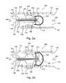
- balloon 130optionally includes alternative shapes, for example having varied cross sectional diameters. As seen in assembly 300 ( FIG. 3 a ), the diameter associated with a distal portion 133 of deflated balloon 130 is larger than the diameter associated with a proximal portion 139 .
- filter 122reaches a maximal diameter initially as distal balloon portion 133 inflates. In this manner, filter 122 is fully in position and expanded prior to inflation of proximal balloon portion 139 .
- proximal balloon portion 139has been fully inflated to compress lesion 144 , thereby releasing debris 160 that is captured by filter 122 .
- the many options for configuring alternative shapes of balloon 130are well known to those familiar with the art.
- balloon 130is seen having an overall length 209 of approximately 38 millimeters and a maximal inflation diameter 211 of approximately 5 millimeters.
- balloon 130is shown with a proximal portion 207 having a length 235 of approximately 18 millimeters and a distal portion 208 having a length 233 of approximately 18 millimeters.
- filter 122extends to substantially cover distal portion 208 while proximal portion 207 is unprotected by filter 122 .
- filter 122optionally substantially fully covers distal balloon portion 208 and extends over at least a portion of proximal balloon portion 207 ; the many configurations of assembly 400 being well known to those familiar with the art.
- Assembly 500( FIGS. 5 a - 5 e ) demonstrates just one more of the many embodiments of the instant invention that are easily contemplated by those familiar with the art.
- Assembly 500comprises a proximal balloon 230 and a distal balloon 101 .
- distal balloon 101is inflated to expand filter 122 and substantially take up the volume within filter 122 .
- proximal balloon 230is inflated separately and pressed against lesion 144 .
- distal balloon 101After deflation of proximal balloon 230 as seen in FIG. 5 d , distal balloon 101 remains inflated so that debris 160 remains proximal to distal balloon 101 . Upon deflation of distal balloon 101 , debris 160 enters and is captured by filter 122 .
- assemblies 100 - 500have been described with respect to vessel 141 , assemblies 100 - 500 can be easily configured for use in a wide variety of in vivo lumens 142 including inter alia: a lumen of a urethra, a biliary lumen and/or a renal calyx lumen. Additionally or alternatively, filter 122 can be easily modified to capture debris in virtually any in vivo lumen 142 including, inter alia: biliary stones and/or renal stones. The many applications, modifications and configurations of assemblies 100 - 500 for use in virtually any in vivo lumen 142 will be readily apparent to those familiar with the art.
- filter 122comprises a sheet material configured to extend distally with respect to balloon 130 while filter 122 is expanded.
- the sheet material of filter 122is selected from the group consisting of: meshes and nets.
- bending of a portion of the sheet material of filter 122forms filter cord channel 120 .
- attaching a shaped component to filter 122forms filter cord channel 120 .
- the material of filter 122has a thickness of at least about 20 microns. In embodiments, the material of filter 122 has a thickness of no more than about 200 microns. In embodiments, the material of filter 122 includes apertures having diameters of at least about 20 microns. In embodiments, the material of filter 122 includes apertures having diameters of no more than about 80 microns in diameter. In embodiments, the material of filter 122 is manufactured using a technique from the group of techniques consisting of: interlacing, knitting, weaving, braiding, knotting, wrapping, and electro spinning.
- filter 122is configured to expand to a cross sectional diameter of at least about 1.0 millimeters. In embodiments, filter 122 is configured to expand to a cross sectional diameter of no more than about 6.0 millimeters. In embodiments, the extent of the expansion of filter 122 is configured to be limited by the walls of luminal aspect 140 in which filter 122 is deployed.
- balloon 130has a maximum inflation diameter of at least about 1.0 millimeter. In embodiments, balloon 130 has a maximum inflation diameter of no more than about 6.0 millimeters.
- balloon 130has a wall thickness of at least about 0.2 millimeters. In embodiments, balloon 130 has a wall thickness of no more than about 0.5 millimeters.
- strut 128has a substantially circular cross section having a diameter of at least about 0.1 millimeters. In embodiments, strut 128 has a substantially circular cross section having a diameter of no more than about 0.6 millimeters.
- strut 128has a cross section having greater and lesser measurements and the greater measurement is at least about 0.1 millimeters. In embodiments, strut 128 has a cross section having greater and lesser measurements and the greater measurement is no more than about 0.6 millimeters. In embodiments, strut 128 has a cross section having greater and lesser measurements and the lesser measurement is at least about 0.1 millimeters. In embodiments, strut 128 has a cross section having greater and lesser measurements and the lesser measurement is no more than about 0.6 millimeters.
- filter 122has an internal and an external aspect and strut 128 is attached to the internal aspect or the external aspect of filter 122 .
- strut 128is attached to filter 122 using a process selected from the group consisting of: sewing, adhesion, gluing, suturing, riveting and welding.
- cord channel 120comprises at least two cord channels; and cord 112 comprises at least two cords.
- catheter 132has an outside diameter of at least about 1.0 millimeter. In embodiments, catheter 132 has an outside diameter of no more than about 5.0 millimeters. In embodiments, catheter 132 has a length of at least about 0.8 meter. In embodiments, catheter 132 has a length of no more than about 1.5 meters.
- the walls of catheter 132 compression sleeve 134have a thickness of at least about 2 millimeters. In embodiments, the walls of catheter 132 compression sleeve 134 have a thickness of more than about 5 millimeters.
- filter 122 , cord 110 ( FIG. 1 a ) and cord 112 ( FIG. 2 a ), strut 128 , compression sleeve 134 , and catheter 132comprise a material from the group consisting of: polyethylene, polyvinyl chloride, polyurethane and nylon.
- filter 122 , cord 110 ( FIG. 1 a ) and cord 112 ( FIG. 2 a ), strut 128 , compression sleeve 134 , and catheter 132comprise a material selected from the group consisting of: nitinol, stainless steel shape memory materials, metals, synthetic biostable polymer, a natural polymer, and an inorganic material.
- the biostable polymercomprises a material from the group consisting of: a polyolefin, a polyurethane, a fluorinated polyolefin, a chlorinated polyolefin, a polyamide, an acrylate polymer, an acrylamide polymer, a vinyl polymer, a polyacetal, a polycarbonate, a polyether, an aromatic polyester, a polyether (ether keto), a polysulfone, a silicone rubber, a thermoset, and a polyester (ester imide).
- the natural polymercomprises a material from the group consisting of: a polyolefin, a polyurethane, a Mylar, a silicone, a polyester and a fluorinated polyolefin.
- filter 122 , cord 110 ( FIG. 1 a ) and cord 112 ( FIG. 2 a ), strut 128 , compression sleeve 134 , and catheter 132comprise a material having a property selected from the group consisting of: compliant, flexible, plastic, and rigid.
Landscapes
- Health & Medical Sciences (AREA)
- Heart & Thoracic Surgery (AREA)
- Life Sciences & Earth Sciences (AREA)
- General Health & Medical Sciences (AREA)
- Public Health (AREA)
- Biomedical Technology (AREA)
- Veterinary Medicine (AREA)
- Vascular Medicine (AREA)
- Engineering & Computer Science (AREA)
- Animal Behavior & Ethology (AREA)
- Oral & Maxillofacial Surgery (AREA)
- Cardiology (AREA)
- Transplantation (AREA)
- Child & Adolescent Psychology (AREA)
- Biophysics (AREA)
- Pulmonology (AREA)
- Anesthesiology (AREA)
- Hematology (AREA)
- Surgical Instruments (AREA)
- Materials For Medical Uses (AREA)
Abstract
Description
- 1) the additional thousands of dollars to pay for each disposable filter for each surgery;
- 2) the difficulty in surgically deploying the filter in addition to a balloon angioplasty; and
- 3) the additional surgical fee charged by the surgeon for performing a second surgical procedure associated with the filter.
Claims (20)
Priority Applications (1)
| Application Number | Priority Date | Filing Date | Title |
|---|---|---|---|
| US13/237,977US9132261B2 (en) | 2006-10-18 | 2011-09-21 | In vivo filter assembly |
Applications Claiming Priority (2)
| Application Number | Priority Date | Filing Date | Title |
|---|---|---|---|
| US11/582,354US8043323B2 (en) | 2006-10-18 | 2006-10-18 | In vivo filter assembly |
| US13/237,977US9132261B2 (en) | 2006-10-18 | 2011-09-21 | In vivo filter assembly |
Related Parent Applications (1)
| Application Number | Title | Priority Date | Filing Date |
|---|---|---|---|
| US11/582,354DivisionUS8043323B2 (en) | 2005-05-24 | 2006-10-18 | In vivo filter assembly |
Publications (2)
| Publication Number | Publication Date |
|---|---|
| US20120010649A1 US20120010649A1 (en) | 2012-01-12 |
| US9132261B2true US9132261B2 (en) | 2015-09-15 |
Family
ID=39618362
Family Applications (2)
| Application Number | Title | Priority Date | Filing Date |
|---|---|---|---|
| US11/582,354Expired - Fee RelatedUS8043323B2 (en) | 2005-05-24 | 2006-10-18 | In vivo filter assembly |
| US13/237,977Active2029-07-23US9132261B2 (en) | 2006-10-18 | 2011-09-21 | In vivo filter assembly |
Family Applications Before (1)
| Application Number | Title | Priority Date | Filing Date |
|---|---|---|---|
| US11/582,354Expired - Fee RelatedUS8043323B2 (en) | 2005-05-24 | 2006-10-18 | In vivo filter assembly |
Country Status (1)
| Country | Link |
|---|---|
| US (2) | US8043323B2 (en) |
Families Citing this family (11)
| Publication number | Priority date | Publication date | Assignee | Title |
|---|---|---|---|---|
| US20070233174A1 (en)* | 2005-04-01 | 2007-10-04 | Gordon Hocking | Trapping Filter for Blood Vessel |
| US8961586B2 (en) | 2005-05-24 | 2015-02-24 | Inspiremd Ltd. | Bifurcated stent assemblies |
| US8043323B2 (en) | 2006-10-18 | 2011-10-25 | Inspiremd Ltd. | In vivo filter assembly |
| CA2609687C (en) | 2005-05-24 | 2014-04-22 | Inspire M.D Ltd. | Stent apparatuses for treatment via body lumens and methods of use |
| WO2008047369A2 (en) | 2006-10-18 | 2008-04-24 | Inspiremd Ltd. | Knitted stent jackets |
| CA2666712C (en)* | 2006-10-18 | 2015-03-31 | Asher Holzer | Filter assemblies |
| EP3292837B1 (en) | 2006-11-22 | 2022-11-09 | Inspire M.D Ltd | Optimized stent jacket |
| US20110230717A1 (en)* | 2010-03-18 | 2011-09-22 | Gyrus Acmi, Inc. | Flexible endoscope external joint |
| US9844395B2 (en)* | 2013-03-14 | 2017-12-19 | Cook Medical Technologies Llc | Umbrella inferior vena cava filter retrieval device |
| US10010398B2 (en) | 2013-10-01 | 2018-07-03 | Cook Medical Technologies Llc | Filter device, system, and method |
| CN112823754A (en)* | 2019-11-19 | 2021-05-21 | 广州是知投资咨询合伙企业(有限合伙) | Balloon dilatation catheter and application thereof |
Citations (167)
| Publication number | Priority date | Publication date | Assignee | Title |
|---|---|---|---|---|
| US4164045A (en) | 1977-08-03 | 1979-08-14 | Carbomedics, Inc. | Artificial vascular and patch grafts |
| US4300244A (en) | 1979-09-19 | 1981-11-17 | Carbomedics, Inc. | Cardiovascular grafts |
| US4321711A (en) | 1978-10-18 | 1982-03-30 | Sumitomo Electric Industries, Ltd. | Vascular prosthesis |
| US4425908A (en) | 1981-10-22 | 1984-01-17 | Beth Israel Hospital | Blood clot filter |
| US4723549A (en) | 1986-09-18 | 1988-02-09 | Wholey Mark H | Method and apparatus for dilating blood vessels |
| WO1988009683A1 (en) | 1987-06-10 | 1988-12-15 | Kletschka Harold D | An angioplasty device |
| US4832688A (en) | 1986-04-09 | 1989-05-23 | Terumo Kabushiki Kaisha | Catheter for repair of blood vessel |
| US4865017A (en) | 1987-07-10 | 1989-09-12 | Olympus Optical Co., Ltd. | Endoscopic operation instrument |
| US4873978A (en) | 1987-12-04 | 1989-10-17 | Robert Ginsburg | Device and method for emboli retrieval |
| US4969891A (en) | 1989-03-06 | 1990-11-13 | Gewertz Bruce L | Removable vascular filter |
| US4990156A (en) | 1988-06-21 | 1991-02-05 | Lefebvre Jean Marie | Filter for medical use |
| US4998539A (en) | 1987-12-18 | 1991-03-12 | Delsanti Gerard L | Method of using removable endo-arterial devices to repair detachments in the arterial walls |
| US5019090A (en) | 1988-09-01 | 1991-05-28 | Corvita Corporation | Radially expandable endoprosthesis and the like |
| US5122154A (en) | 1990-08-15 | 1992-06-16 | Rhodes Valentine J | Endovascular bypass graft |
| US5152777A (en) | 1989-01-25 | 1992-10-06 | Uresil Corporation | Device and method for providing protection from emboli and preventing occulsion of blood vessels |
| US5171233A (en) | 1990-04-25 | 1992-12-15 | Microvena Corporation | Snare-type probe |
| US5192286A (en) | 1991-07-26 | 1993-03-09 | Regents Of The University Of California | Method and device for retrieving materials from body lumens |
| US5236447A (en) | 1990-06-29 | 1993-08-17 | Nissho Corporation | Artificial tubular organ |
| US5330482A (en) | 1991-06-17 | 1994-07-19 | Wilson-Cook Medical Inc. | Endoscopic extraction devices, wire basket stone extractors, stent retrievers, snares and method of constructing the same |
| US5366504A (en) | 1992-05-20 | 1994-11-22 | Boston Scientific Corporation | Tubular medical prosthesis |
| US5382261A (en) | 1992-09-01 | 1995-01-17 | Expandable Grafts Partnership | Method and apparatus for occluding vessels |
| US5383887A (en) | 1992-12-28 | 1995-01-24 | Celsa Lg | Device for selectively forming a temporary blood filter |
| US5403341A (en) | 1994-01-24 | 1995-04-04 | Solar; Ronald J. | Parallel flow endovascular stent and deployment apparatus therefore |
| US5421955A (en) | 1991-10-28 | 1995-06-06 | Advanced Cardiovascular Systems, Inc. | Expandable stents and method for making same |
| US5470313A (en) | 1994-02-24 | 1995-11-28 | Cardiovascular Dynamics, Inc. | Variable diameter balloon dilatation catheter |
| US5486183A (en) | 1990-10-09 | 1996-01-23 | Raychem Corporation | Device or apparatus for manipulating matter |
| US5569295A (en) | 1993-12-28 | 1996-10-29 | Advanced Cardiovascular Systems, Inc. | Expandable stents and method for making same |
| US5591228A (en) | 1995-05-09 | 1997-01-07 | Edoga; John K. | Methods for treating abdominal aortic aneurysms |
| US5713948A (en) | 1995-07-19 | 1998-02-03 | Uflacker; Renan | Adjustable and retrievable graft and graft delivery system for stent-graft system |
| EP0839506A1 (en) | 1996-10-22 | 1998-05-06 | Nitinol Development Corporation | A composite stent |
| US5769884A (en) | 1996-06-27 | 1998-06-23 | Cordis Corporation | Controlled porosity endovascular implant |
| US5824037A (en) | 1995-10-03 | 1998-10-20 | Medtronic, Inc. | Modular intraluminal prostheses construction and methods |
| US5827324A (en) | 1997-03-06 | 1998-10-27 | Scimed Life Systems, Inc. | Distal protection device |
| US5833651A (en) | 1996-11-08 | 1998-11-10 | Medtronic, Inc. | Therapeutic intraluminal stents |
| US5843161A (en) | 1996-06-26 | 1998-12-01 | Cordis Corporation | Endoprosthesis assembly for percutaneous deployment and method of deploying same |
| US5843116A (en) | 1996-05-02 | 1998-12-01 | Cardiovascular Dynamics, Inc. | Focalized intraluminal balloons |
| US5871538A (en) | 1992-12-21 | 1999-02-16 | Corvita Corporation | Luminal graft endoprotheses and manufacture thereof |
| US5908448A (en) | 1993-09-30 | 1999-06-01 | Boston Scientific Corporation | Controlled deployment of a medical device |
| WO1999029262A1 (en) | 1997-12-10 | 1999-06-17 | William A. Cook Australia Pty. Ltd. | Endoluminal aortic stents |
| US5919225A (en) | 1994-09-08 | 1999-07-06 | Gore Enterprise Holdings, Inc. | Procedures for introducing stents and stent-grafts |
| US5941896A (en) | 1997-09-08 | 1999-08-24 | Montefiore Hospital And Medical Center | Filter and method for trapping emboli during endovascular procedures |
| US5984955A (en) | 1997-09-11 | 1999-11-16 | Wisselink; Willem | System and method for endoluminal grafting of bifurcated or branched vessels |
| US6007543A (en) | 1996-08-23 | 1999-12-28 | Scimed Life Systems, Inc. | Stent delivery system with stent securement means |
| US6015432A (en) | 1998-02-25 | 2000-01-18 | Cordis Corporation | Wire reinforced vascular prosthesis |
| US6015430A (en) | 1987-12-08 | 2000-01-18 | Wall; William H. | Expandable stent having a fabric liner |
| US6027517A (en) | 1994-02-24 | 2000-02-22 | Radiance Medical Systems, Inc. | Fixed focal balloon for interactive angioplasty and stent implantation catheter with focalized balloon |
| US6030414A (en) | 1997-11-13 | 2000-02-29 | Taheri; Syde A. | Variable stent and method for treatment of arterial disease |
| US6042597A (en) | 1998-10-23 | 2000-03-28 | Scimed Life Systems, Inc. | Helical stent design |
| US6077273A (en) | 1996-08-23 | 2000-06-20 | Scimed Life Systems, Inc. | Catheter support for stent delivery |
| US6096027A (en) | 1998-09-30 | 2000-08-01 | Impra, Inc., A Subsidiary Of C.R. Bard, Inc. | Bag enclosed stent loading apparatus |
| US6152144A (en) | 1998-11-06 | 2000-11-28 | Appriva Medical, Inc. | Method and device for left atrial appendage occlusion |
| US6176875B1 (en) | 1996-01-05 | 2001-01-23 | Medtronic, Inc. | Limited expansion endoluminal prostheses and methods for their use |
| WO2001030266A1 (en) | 1999-10-27 | 2001-05-03 | Atritech, Inc. | Filter apparatus for ostium of left atrial appendage |
| US6245089B1 (en)* | 1997-03-06 | 2001-06-12 | Scimed Life Systems, Inc. | Distal protection device and method |
| US6254627B1 (en) | 1997-09-23 | 2001-07-03 | Diseno Y Desarrollo Medico S.A. De C.V. | Non-thrombogenic stent jacket |
| US6263880B1 (en) | 1998-06-22 | 2001-07-24 | Neovasys, Inc. | Method of enhancing blood flow in tissue |
| US6306162B1 (en) | 1999-12-15 | 2001-10-23 | Advanced Cardiovascular Systems, Inc. | Stent delivery system utilizing novel balloon for obtaining variable post-deployment stent characteristics |
| US6340364B2 (en) | 1999-10-22 | 2002-01-22 | Nozomu Kanesaka | Vascular filtering device |
| US6348065B1 (en) | 1995-03-01 | 2002-02-19 | Scimed Life Systems, Inc. | Longitudinally flexible expandable stent |
| US20020022860A1 (en) | 2000-08-18 | 2002-02-21 | Borillo Thomas E. | Expandable implant devices for filtering blood flow from atrial appendages |
| US6357104B1 (en) | 1993-08-18 | 2002-03-19 | David J. Myers | Method of making an intraluminal stent graft |
| US6361558B1 (en) | 1998-03-31 | 2002-03-26 | Cordis Neurovascular, Inc. | Stent aneurysm treatment system and method |
| US6369039B1 (en) | 1998-06-30 | 2002-04-09 | Scimed Life Sytems, Inc. | High efficiency local drug delivery |
| US20020045917A1 (en) | 1998-04-29 | 2002-04-18 | Embol-X, Inc. | Adjustable blood filtration system |
| US6383171B1 (en) | 1999-10-12 | 2002-05-07 | Allan Will | Methods and devices for protecting a passageway in a body when advancing devices through the passageway |
| US20020082685A1 (en) | 2000-12-22 | 2002-06-27 | Motasim Sirhan | Apparatus and methods for controlled substance delivery from implanted prostheses |
| US6432129B2 (en) | 2000-02-22 | 2002-08-13 | Scimed Life Systems, Inc. | Stent delivery system |
| US20020111668A1 (en) | 1999-08-11 | 2002-08-15 | Scimed Life Systems, Inc. | Seamless braided or spun stent cover |
| US6436132B1 (en) | 2000-03-30 | 2002-08-20 | Advanced Cardiovascular Systems, Inc. | Composite intraluminal prostheses |
| US6447796B1 (en) | 1994-05-16 | 2002-09-10 | The United States Of America As Represented By The Secretary Of The Army | Sustained release hydrophobic bioactive PLGA microspheres |
| US20020128679A1 (en) | 2001-03-08 | 2002-09-12 | Embol-X, Inc. | Cerebral protection during carotid endarterectomy and methods of use |
| US6451051B2 (en) | 1999-04-26 | 2002-09-17 | William J. Drasler | Intravascular folded tubular endoprosthesis |
| US6461381B2 (en) | 1994-03-17 | 2002-10-08 | Medinol, Ltd. | Flexible expandable stent |
| US6464722B2 (en) | 1994-03-17 | 2002-10-15 | Medinol, Ltd. | Flexible expandable stent |
| US6468230B2 (en) | 1998-02-19 | 2002-10-22 | Medtronic Percusurge, Inc. | Core wire with shapeable tip |
| US20020161393A1 (en) | 1999-07-30 | 2002-10-31 | Demond Jackson F. | Vascular device for emboli and thrombi removal and methods of use |
| US6506203B1 (en) | 2000-12-19 | 2003-01-14 | Advanced Cardiovascular Systems, Inc. | Low profile sheathless embolic protection system |
| US20030028239A1 (en) | 2001-07-03 | 2003-02-06 | Boston Scientific Corp | Low profile, high stretch knit prosthetic device |
| WO2003018079A1 (en) | 2001-08-27 | 2003-03-06 | Scimed Life Systems, Inc. | Medical devices utilizing melt-processible poly(tetrafluoroethylene) |
| US20030055452A1 (en) | 2001-09-19 | 2003-03-20 | Joergensen Ib Erling | Methods and apparatus for distal protection during a medical procedure |
| WO2003022325A2 (en) | 2001-09-10 | 2003-03-20 | Rafael Medical Technologies Inc. | Intravascular devices, retrieval systems, and corresponding methods |
| US6554855B1 (en) | 2001-07-03 | 2003-04-29 | Scimed Life Systems, Inc. | Low profile, high stretch, low dilation knit prosthetic device |
| CN1414840A (en) | 1999-12-29 | 2003-04-30 | 爱德华兹生命科学公司 | Vascular grafts for bridging vessel side branch and its method |
| US20030093112A1 (en) | 1998-11-24 | 2003-05-15 | Embol-X, Inc. | Compliant framework and methods of use |
| US20030100945A1 (en) | 2001-11-23 | 2003-05-29 | Mindguard Ltd. | Implantable intraluminal device and method of using same in treating aneurysms |
| US20030130718A1 (en) | 1999-11-19 | 2003-07-10 | Palmas Julio C. | Endoluminal implantable stent-grafts |
| US6602285B1 (en) | 1998-09-05 | 2003-08-05 | Jomed Gmbh | Compact stent |
| US20030176884A1 (en) | 2002-03-12 | 2003-09-18 | Marwane Berrada | Everted filter device |
| US6641607B1 (en) | 2000-12-29 | 2003-11-04 | Advanced Cardiovascular Systems, Inc. | Double tube stent |
| US6645239B1 (en) | 1999-08-18 | 2003-11-11 | Jae-Hyung Park | Flexible and self-expandable stent and inserting device for such stents |
| US20030229389A1 (en) | 2000-05-01 | 2003-12-11 | Escano Arnold M. | Lock modular graft component junctions |
| US6669717B2 (en) | 1998-02-12 | 2003-12-30 | Thomas R. Marotta | Endovascular prosthesis |
| US6669961B2 (en) | 2000-08-15 | 2003-12-30 | Board Of Trustees Of University Of Illinois | Microparticles |
| US6673814B2 (en) | 1997-08-19 | 2004-01-06 | Emory University | Delivery systems and methods for noscapine and noscapine derivatives, useful as anticancer agents |
| US6676695B2 (en) | 2001-05-30 | 2004-01-13 | Jan Otto Solem | Vascular instrument and method |
| US6682554B2 (en) | 1998-09-05 | 2004-01-27 | Jomed Gmbh | Methods and apparatus for a stent having an expandable web structure |
| US20040030377A1 (en) | 2001-10-19 | 2004-02-12 | Alexander Dubson | Medicated polymer-coated stent assembly |
| US6702849B1 (en) | 1999-12-13 | 2004-03-09 | Advanced Cardiovascular Systems, Inc. | Method of processing open-celled microcellular polymeric foams with controlled porosity for use as vascular grafts and stent covers |
| US20040054402A1 (en) | 2002-09-16 | 2004-03-18 | Dicarlo Paul | Devices and methods for AAA management |
| US6712834B2 (en) | 1998-06-16 | 2004-03-30 | Mindguard Ltd. | Implantable blood filtering device |
| US20040068314A1 (en) | 2002-01-16 | 2004-04-08 | Jones Donald K. | Detachable self -expanding aneurysm cover device |
| US20040111142A1 (en) | 2000-02-01 | 2004-06-10 | Rourke Jonathan M. | Micro-porous mesh stent with hybrid structure |
| US20040116960A1 (en) | 1999-07-30 | 2004-06-17 | Scimed Life Systems, Inc. | One piece loop and coil |
| US6755856B2 (en) | 1998-09-05 | 2004-06-29 | Abbott Laboratories Vascular Enterprises Limited | Methods and apparatus for stenting comprising enhanced embolic protection, coupled with improved protection against restenosis and thrombus formation |
| US20040143272A1 (en) | 2003-01-17 | 2004-07-22 | Cully Edward H. | Deployment system for an endoluminal device |
| US20040158312A1 (en) | 2000-01-31 | 2004-08-12 | Chouinard Paul F. | Braided endoluminal device having tapered filaments |
| US6802851B2 (en) | 2001-09-20 | 2004-10-12 | Gordia Neurovascular, Inc. | Stent aneurysm embolization method using collapsible member and embolic coils |
| US6808533B1 (en) | 2000-07-28 | 2004-10-26 | Atrium Medical Corporation | Covered stent and method of covering a stent |
| US20040225322A1 (en) | 2003-03-19 | 2004-11-11 | Garrison Michael L. | Delivery systems and methods for deploying expandable intraluminal medical devices |
| US6818014B2 (en) | 1995-03-01 | 2004-11-16 | Scimed Life Systems, Inc. | Longitudinally flexible expandable stent |
| US6827731B2 (en) | 2001-01-22 | 2004-12-07 | Gore Enterprise Holdings, Inc. | Deployment system for intraluminal devices |
| US6835189B2 (en) | 2002-10-15 | 2004-12-28 | Scimed Life Systems, Inc. | Controlled deployment balloon |
| US20040267347A1 (en) | 2003-05-01 | 2004-12-30 | Cervantes Marvin John | Protective elongated sleeve for stent systems |
| US20040267352A1 (en) | 1999-01-13 | 2004-12-30 | Davidson Charles J. | Stent with protruding branch portion for bifurcated vessels |
| US20050038503A1 (en) | 2003-05-29 | 2005-02-17 | Secor Medical, Llc | Filament based prosthesis |
| US20050049680A1 (en) | 2003-09-03 | 2005-03-03 | Fischell Tim A. | Side branch stent with split proximal end |
| US20050110214A1 (en) | 2003-11-25 | 2005-05-26 | Shank Peter J. | Composite stent with inner and outer stent elements and method of using the same |
| US20050119688A1 (en) | 2003-10-06 | 2005-06-02 | Bjarne Bergheim | Method and assembly for distal embolic protection |
| US6902522B1 (en) | 2000-06-12 | 2005-06-07 | Acorn Cardiovascular, Inc. | Cardiac disease treatment and device |
| US6918920B1 (en) | 2001-11-01 | 2005-07-19 | Advanced Cardiovascular Systems, Inc. | Catheter having an improved distal tip |
| US6919100B2 (en) | 2003-01-22 | 2005-07-19 | Cordis Corporation | Method for coating medical devices |
| US20050171591A1 (en) | 2004-01-29 | 2005-08-04 | Scimed Life Systems, Inc. | Catherter tip |
| US6929658B1 (en) | 2000-03-09 | 2005-08-16 | Design & Performance-Cyprus Limited | Stent with cover connectors |
| US20050182473A1 (en) | 2004-02-18 | 2005-08-18 | Tracee Eidenschink | Multi stent delivery system |
| US6932832B2 (en) | 2000-10-20 | 2005-08-23 | Angiodynamics, Inc. | Convertible blood clot filter |
| US20050187140A1 (en) | 2003-11-20 | 2005-08-25 | Angiotech International Ag | Polymer compositions and methods for their use |
| US6939376B2 (en) | 2001-11-05 | 2005-09-06 | Sun Biomedical, Ltd. | Drug-delivery endovascular stent and method for treating restenosis |
| US6939374B2 (en) | 2001-12-21 | 2005-09-06 | Scimed Life Systems, Inc. | Stents, stenting systems, and related methods for agent delivery |
| US20050222607A1 (en) | 1999-12-23 | 2005-10-06 | Olin Palmer | Snare |
| US6953476B1 (en) | 2000-03-27 | 2005-10-11 | Neovasc Medical Ltd. | Device and method for treating ischemic heart disease |
| US20050277976A1 (en) | 2004-05-27 | 2005-12-15 | Galdonik Jason A | Emboli filter export system |
| US6981986B1 (en) | 1995-03-01 | 2006-01-03 | Boston Scientific Scimed, Inc. | Longitudinally flexible expandable stent |
| US20060009835A1 (en) | 2004-07-07 | 2006-01-12 | Osborne Thomas A | Graft, stent graft and method |
| WO2006010130A1 (en) | 2004-07-09 | 2006-01-26 | University Of Florida Research Foundation, Inc. | Tubular polymer stent coverings |
| US6997946B2 (en) | 2002-11-27 | 2006-02-14 | Boston Scientific Scimed, Inc. | Expandable stents |
| US7011676B2 (en) | 2002-09-05 | 2006-03-14 | Scimed Life Systems, Inc. | Flat knitted stent and method of making the same |
| US20060085064A1 (en) | 1993-04-26 | 2006-04-20 | Medtronic, Inc. | Medical devices for delivering a therapeutic agent and method of preparation |
| US7037330B1 (en) | 2000-10-16 | 2006-05-02 | Scimed Life Systems, Inc. | Neurovascular stent and method |
| US20060116748A1 (en) | 2003-04-14 | 2006-06-01 | Aaron Kaplan | Stepped balloon catheter for treating vascular bifurcations |
| US20060155359A1 (en) | 2005-01-13 | 2006-07-13 | Medtronic Vascular, Inc. | Branch vessel graft design and deployment method |
| US7083644B1 (en) | 2000-05-24 | 2006-08-01 | Scimed Life Systems, Inc. | Implantable prostheses with improved mechanical and chemical properties |
| US20060175727A1 (en) | 2001-09-28 | 2006-08-10 | Abbott Laboratories Vascular Enterprises Limited | Porous membranes for medical implants and methods of manufacture |
| WO2006116636A1 (en) | 2005-04-28 | 2006-11-02 | The Cleveland Clinic Foundation | Stent with integrated filter |
| US20060259131A1 (en) | 2005-05-16 | 2006-11-16 | Masoud Molaei | Medical devices including metallic films and methods for making same |
| US20060259137A1 (en) | 2003-10-06 | 2006-11-16 | Jason Artof | Minimally invasive valve replacement system |
| WO2006126182A2 (en) | 2005-05-24 | 2006-11-30 | Inspire M.D Ltd. | Stent apparatuses for treatment via body lumens and methods of use |
| US20070043428A1 (en) | 2005-03-09 | 2007-02-22 | The University Of Tennessee Research Foundation | Barrier stent and use thereof |
| WO2007067451A2 (en) | 2005-12-07 | 2007-06-14 | C. R. Bard, Inc. | Vena cava filter with stent |
| US20070208374A1 (en) | 1999-12-30 | 2007-09-06 | Advanced Cardiovascular Systems, Inc. | Embolic protection devices |
| US20070270902A1 (en) | 2004-09-17 | 2007-11-22 | Slazas Robert R | Thin Film Metallic Devices for Plugging Aneurysms or Vessels |
| US20070276468A1 (en) | 2005-05-24 | 2007-11-29 | Inspiremd Ltd. | Bifurcated stent assemblies |
| US20080023346A1 (en) | 2004-06-10 | 2008-01-31 | Design & Performance - Cyprus Limited | Protected Stent Delivery System and Packaging |
| WO2008047368A2 (en) | 2006-10-18 | 2008-04-24 | Inspiremd Ltd. | Filter assemblies |
| WO2008047369A2 (en) | 2006-10-18 | 2008-04-24 | Inspiremd Ltd. | Knitted stent jackets |
| WO2008062414A2 (en) | 2006-11-22 | 2008-05-29 | Inspiremd Ltd. | Optimized stent jacket |
| US20080172082A1 (en) | 2006-10-18 | 2008-07-17 | Inspiremd Ltd. | In vivo filter assembly |
| US20090012598A1 (en) | 2004-06-29 | 2009-01-08 | Abbate Anthony J | Method of fabricating an implantable medical device by deformation of a tube or a sheet |
| US7491225B2 (en) | 2005-02-16 | 2009-02-17 | Boston Scientific Scimed, Inc. | System and method for deploying a drug-eluting external body and tissue scaffold |
| US7594926B2 (en)* | 2001-11-09 | 2009-09-29 | Boston Scientific Scimed, Inc. | Methods, systems and devices for delivering stents |
| US20090248133A1 (en) | 2008-04-01 | 2009-10-01 | Medtronic Vascular, Inc. | Double-Walled Stent System |
| US20100056907A1 (en) | 2008-08-20 | 2010-03-04 | Sensible Medical Innovations Ltd. | Methods and devices of cardaic tissue monitoring and analysis |
| US7722634B2 (en) | 2003-07-03 | 2010-05-25 | Regents Of The University Of Minnesota | Medical device and method of intravenous filtration |
| US20100222805A1 (en) | 2005-07-12 | 2010-09-02 | Cook Incorporated | Methods for embolic protection during treatment of a stenotic lesion in a body vessel |
| US20100324664A1 (en) | 2006-10-18 | 2010-12-23 | Asher Holzer | Bifurcated Stent Assemblies |
| US20110098739A1 (en) | 2005-12-21 | 2011-04-28 | Nexeon Medsystems, Inc. | Interventional catheter for retrograde use having embolic protection capability and methods of use |
| US7996993B2 (en) | 1997-11-03 | 2011-08-16 | C. R. Bard, Inc. | Temporary vascular filter guide wire |
| US8097015B2 (en) | 2003-09-12 | 2012-01-17 | W.L. Gore & Associates, Inc. | Device and methods for preventing formation of thrombi in the left atrial appendage |
Family Cites Families (1)
| Publication number | Priority date | Publication date | Assignee | Title |
|---|---|---|---|---|
| US6832189B1 (en)* | 2000-11-15 | 2004-12-14 | International Business Machines Corporation | Integration of speech recognition and stenographic services for improved ASR training |
- 2006
- 2006-10-18USUS11/582,354patent/US8043323B2/ennot_activeExpired - Fee Related
- 2011
- 2011-09-21USUS13/237,977patent/US9132261B2/enactiveActive
Patent Citations (187)
| Publication number | Priority date | Publication date | Assignee | Title |
|---|---|---|---|---|
| US4164045A (en) | 1977-08-03 | 1979-08-14 | Carbomedics, Inc. | Artificial vascular and patch grafts |
| US4321711A (en) | 1978-10-18 | 1982-03-30 | Sumitomo Electric Industries, Ltd. | Vascular prosthesis |
| US4300244A (en) | 1979-09-19 | 1981-11-17 | Carbomedics, Inc. | Cardiovascular grafts |
| US4425908A (en) | 1981-10-22 | 1984-01-17 | Beth Israel Hospital | Blood clot filter |
| US4832688A (en) | 1986-04-09 | 1989-05-23 | Terumo Kabushiki Kaisha | Catheter for repair of blood vessel |
| US4723549A (en) | 1986-09-18 | 1988-02-09 | Wholey Mark H | Method and apparatus for dilating blood vessels |
| WO1988009683A1 (en) | 1987-06-10 | 1988-12-15 | Kletschka Harold D | An angioplasty device |
| US4865017A (en) | 1987-07-10 | 1989-09-12 | Olympus Optical Co., Ltd. | Endoscopic operation instrument |
| US4873978A (en) | 1987-12-04 | 1989-10-17 | Robert Ginsburg | Device and method for emboli retrieval |
| US6015430A (en) | 1987-12-08 | 2000-01-18 | Wall; William H. | Expandable stent having a fabric liner |
| US4998539A (en) | 1987-12-18 | 1991-03-12 | Delsanti Gerard L | Method of using removable endo-arterial devices to repair detachments in the arterial walls |
| US4990156A (en) | 1988-06-21 | 1991-02-05 | Lefebvre Jean Marie | Filter for medical use |
| US5019090A (en) | 1988-09-01 | 1991-05-28 | Corvita Corporation | Radially expandable endoprosthesis and the like |
| US5152777A (en) | 1989-01-25 | 1992-10-06 | Uresil Corporation | Device and method for providing protection from emboli and preventing occulsion of blood vessels |
| US4969891A (en) | 1989-03-06 | 1990-11-13 | Gewertz Bruce L | Removable vascular filter |
| US5171233A (en) | 1990-04-25 | 1992-12-15 | Microvena Corporation | Snare-type probe |
| US5236447A (en) | 1990-06-29 | 1993-08-17 | Nissho Corporation | Artificial tubular organ |
| US5122154A (en) | 1990-08-15 | 1992-06-16 | Rhodes Valentine J | Endovascular bypass graft |
| US5486183A (en) | 1990-10-09 | 1996-01-23 | Raychem Corporation | Device or apparatus for manipulating matter |
| US5330482A (en) | 1991-06-17 | 1994-07-19 | Wilson-Cook Medical Inc. | Endoscopic extraction devices, wire basket stone extractors, stent retrievers, snares and method of constructing the same |
| US5192286A (en) | 1991-07-26 | 1993-03-09 | Regents Of The University Of California | Method and device for retrieving materials from body lumens |
| US5421955A (en) | 1991-10-28 | 1995-06-06 | Advanced Cardiovascular Systems, Inc. | Expandable stents and method for making same |
| US5421955B1 (en) | 1991-10-28 | 1998-01-20 | Advanced Cardiovascular System | Expandable stents and method for making same |
| US6066167A (en) | 1991-10-28 | 2000-05-23 | Advanced Cardiovascular Systems, Inc. | Expandable stents |
| US5366504A (en) | 1992-05-20 | 1994-11-22 | Boston Scientific Corporation | Tubular medical prosthesis |
| US5382261A (en) | 1992-09-01 | 1995-01-17 | Expandable Grafts Partnership | Method and apparatus for occluding vessels |
| US5871538A (en) | 1992-12-21 | 1999-02-16 | Corvita Corporation | Luminal graft endoprotheses and manufacture thereof |
| US5383887A (en) | 1992-12-28 | 1995-01-24 | Celsa Lg | Device for selectively forming a temporary blood filter |
| US20060085064A1 (en) | 1993-04-26 | 2006-04-20 | Medtronic, Inc. | Medical devices for delivering a therapeutic agent and method of preparation |
| US6357104B1 (en) | 1993-08-18 | 2002-03-19 | David J. Myers | Method of making an intraluminal stent graft |
| US5908448A (en) | 1993-09-30 | 1999-06-01 | Boston Scientific Corporation | Controlled deployment of a medical device |
| US5569295A (en) | 1993-12-28 | 1996-10-29 | Advanced Cardiovascular Systems, Inc. | Expandable stents and method for making same |
| US5403341A (en) | 1994-01-24 | 1995-04-04 | Solar; Ronald J. | Parallel flow endovascular stent and deployment apparatus therefore |
| US6027517A (en) | 1994-02-24 | 2000-02-22 | Radiance Medical Systems, Inc. | Fixed focal balloon for interactive angioplasty and stent implantation catheter with focalized balloon |
| US5470313A (en) | 1994-02-24 | 1995-11-28 | Cardiovascular Dynamics, Inc. | Variable diameter balloon dilatation catheter |
| US6461381B2 (en) | 1994-03-17 | 2002-10-08 | Medinol, Ltd. | Flexible expandable stent |
| US6464722B2 (en) | 1994-03-17 | 2002-10-15 | Medinol, Ltd. | Flexible expandable stent |
| US6447796B1 (en) | 1994-05-16 | 2002-09-10 | The United States Of America As Represented By The Secretary Of The Army | Sustained release hydrophobic bioactive PLGA microspheres |
| US5919225A (en) | 1994-09-08 | 1999-07-06 | Gore Enterprise Holdings, Inc. | Procedures for introducing stents and stent-grafts |
| US6818014B2 (en) | 1995-03-01 | 2004-11-16 | Scimed Life Systems, Inc. | Longitudinally flexible expandable stent |
| US6348065B1 (en) | 1995-03-01 | 2002-02-19 | Scimed Life Systems, Inc. | Longitudinally flexible expandable stent |
| US6981986B1 (en) | 1995-03-01 | 2006-01-03 | Boston Scientific Scimed, Inc. | Longitudinally flexible expandable stent |
| US5591228A (en) | 1995-05-09 | 1997-01-07 | Edoga; John K. | Methods for treating abdominal aortic aneurysms |
| US5713948A (en) | 1995-07-19 | 1998-02-03 | Uflacker; Renan | Adjustable and retrievable graft and graft delivery system for stent-graft system |
| US5824037A (en) | 1995-10-03 | 1998-10-20 | Medtronic, Inc. | Modular intraluminal prostheses construction and methods |
| US6176875B1 (en) | 1996-01-05 | 2001-01-23 | Medtronic, Inc. | Limited expansion endoluminal prostheses and methods for their use |
| US5843116A (en) | 1996-05-02 | 1998-12-01 | Cardiovascular Dynamics, Inc. | Focalized intraluminal balloons |
| US5843161A (en) | 1996-06-26 | 1998-12-01 | Cordis Corporation | Endoprosthesis assembly for percutaneous deployment and method of deploying same |
| US5769884A (en) | 1996-06-27 | 1998-06-23 | Cordis Corporation | Controlled porosity endovascular implant |
| US6007543A (en) | 1996-08-23 | 1999-12-28 | Scimed Life Systems, Inc. | Stent delivery system with stent securement means |
| US6077273A (en) | 1996-08-23 | 2000-06-20 | Scimed Life Systems, Inc. | Catheter support for stent delivery |
| US6371962B1 (en) | 1996-08-23 | 2002-04-16 | Scimed Life Systems, Inc. | Stent delivery system with stent securement means |
| EP0839506A1 (en) | 1996-10-22 | 1998-05-06 | Nitinol Development Corporation | A composite stent |
| US5833651A (en) | 1996-11-08 | 1998-11-10 | Medtronic, Inc. | Therapeutic intraluminal stents |
| US6245089B1 (en)* | 1997-03-06 | 2001-06-12 | Scimed Life Systems, Inc. | Distal protection device and method |
| US5827324A (en) | 1997-03-06 | 1998-10-27 | Scimed Life Systems, Inc. | Distal protection device |
| US6673814B2 (en) | 1997-08-19 | 2004-01-06 | Emory University | Delivery systems and methods for noscapine and noscapine derivatives, useful as anticancer agents |
| US5941896A (en) | 1997-09-08 | 1999-08-24 | Montefiore Hospital And Medical Center | Filter and method for trapping emboli during endovascular procedures |
| US5984955A (en) | 1997-09-11 | 1999-11-16 | Wisselink; Willem | System and method for endoluminal grafting of bifurcated or branched vessels |
| US6254627B1 (en) | 1997-09-23 | 2001-07-03 | Diseno Y Desarrollo Medico S.A. De C.V. | Non-thrombogenic stent jacket |
| US7996993B2 (en) | 1997-11-03 | 2011-08-16 | C. R. Bard, Inc. | Temporary vascular filter guide wire |
| US6030414A (en) | 1997-11-13 | 2000-02-29 | Taheri; Syde A. | Variable stent and method for treatment of arterial disease |
| WO1999029262A1 (en) | 1997-12-10 | 1999-06-17 | William A. Cook Australia Pty. Ltd. | Endoluminal aortic stents |
| US6669717B2 (en) | 1998-02-12 | 2003-12-30 | Thomas R. Marotta | Endovascular prosthesis |
| US6468230B2 (en) | 1998-02-19 | 2002-10-22 | Medtronic Percusurge, Inc. | Core wire with shapeable tip |
| US6015432A (en) | 1998-02-25 | 2000-01-18 | Cordis Corporation | Wire reinforced vascular prosthesis |
| US6361558B1 (en) | 1998-03-31 | 2002-03-26 | Cordis Neurovascular, Inc. | Stent aneurysm treatment system and method |
| US20020045917A1 (en) | 1998-04-29 | 2002-04-18 | Embol-X, Inc. | Adjustable blood filtration system |
| US6712834B2 (en) | 1998-06-16 | 2004-03-30 | Mindguard Ltd. | Implantable blood filtering device |
| US6263880B1 (en) | 1998-06-22 | 2001-07-24 | Neovasys, Inc. | Method of enhancing blood flow in tissue |
| US6369039B1 (en) | 1998-06-30 | 2002-04-09 | Scimed Life Sytems, Inc. | High efficiency local drug delivery |
| US20040236407A1 (en) | 1998-09-05 | 2004-11-25 | Abbott Laboratories Vascular Enterprises Limited | Methods and apparatus for stenting comprising enhanced embolic protection coupled with improved protections against restenosis and thrombus formation |
| US6682554B2 (en) | 1998-09-05 | 2004-01-27 | Jomed Gmbh | Methods and apparatus for a stent having an expandable web structure |
| US20070179601A1 (en) | 1998-09-05 | 2007-08-02 | Abbott Laboratories Vascular Enterprises Limited | Methods and apparatus for stenting comprising enhanced embolic protections coupled with improved protections against restenosis and trombus formation |
| US6602285B1 (en) | 1998-09-05 | 2003-08-05 | Jomed Gmbh | Compact stent |
| US20070213800A1 (en) | 1998-09-05 | 2007-09-13 | Abbott Laboratories Vascular Enterprises Limited | Method and apparatus for stenting comprising enhanced embolic protection coupled with improved protections against restenosis and thrombus formation |
| US20070179593A1 (en) | 1998-09-05 | 2007-08-02 | Abbott Laboratories Vascular | Methods and apparatus for stenting comprising enhanced embolic protection coupled with improved protecions against restenosis and thrombus formation |
| US6755856B2 (en) | 1998-09-05 | 2004-06-29 | Abbott Laboratories Vascular Enterprises Limited | Methods and apparatus for stenting comprising enhanced embolic protection, coupled with improved protection against restenosis and thrombus formation |
| US6096027A (en) | 1998-09-30 | 2000-08-01 | Impra, Inc., A Subsidiary Of C.R. Bard, Inc. | Bag enclosed stent loading apparatus |
| US6488703B1 (en) | 1998-10-23 | 2002-12-03 | Scimed Life Systems, Inc. | Helical stent design |
| US6042597A (en) | 1998-10-23 | 2000-03-28 | Scimed Life Systems, Inc. | Helical stent design |
| US6152144A (en) | 1998-11-06 | 2000-11-28 | Appriva Medical, Inc. | Method and device for left atrial appendage occlusion |
| US20030093112A1 (en) | 1998-11-24 | 2003-05-15 | Embol-X, Inc. | Compliant framework and methods of use |
| US20040267352A1 (en) | 1999-01-13 | 2004-12-30 | Davidson Charles J. | Stent with protruding branch portion for bifurcated vessels |
| US6451051B2 (en) | 1999-04-26 | 2002-09-17 | William J. Drasler | Intravascular folded tubular endoprosthesis |
| US20040116960A1 (en) | 1999-07-30 | 2004-06-17 | Scimed Life Systems, Inc. | One piece loop and coil |
| US20020161393A1 (en) | 1999-07-30 | 2002-10-31 | Demond Jackson F. | Vascular device for emboli and thrombi removal and methods of use |
| US20020111668A1 (en) | 1999-08-11 | 2002-08-15 | Scimed Life Systems, Inc. | Seamless braided or spun stent cover |
| US6645239B1 (en) | 1999-08-18 | 2003-11-11 | Jae-Hyung Park | Flexible and self-expandable stent and inserting device for such stents |
| US6712842B1 (en) | 1999-10-12 | 2004-03-30 | Allan Will | Methods and devices for lining a blood vessel and opening a narrowed region of a blood vessel |
| US6383171B1 (en) | 1999-10-12 | 2002-05-07 | Allan Will | Methods and devices for protecting a passageway in a body when advancing devices through the passageway |
| US6340364B2 (en) | 1999-10-22 | 2002-01-22 | Nozomu Kanesaka | Vascular filtering device |
| WO2001030266A1 (en) | 1999-10-27 | 2001-05-03 | Atritech, Inc. | Filter apparatus for ostium of left atrial appendage |
| US20030130718A1 (en) | 1999-11-19 | 2003-07-10 | Palmas Julio C. | Endoluminal implantable stent-grafts |
| US6702849B1 (en) | 1999-12-13 | 2004-03-09 | Advanced Cardiovascular Systems, Inc. | Method of processing open-celled microcellular polymeric foams with controlled porosity for use as vascular grafts and stent covers |
| US6306162B1 (en) | 1999-12-15 | 2001-10-23 | Advanced Cardiovascular Systems, Inc. | Stent delivery system utilizing novel balloon for obtaining variable post-deployment stent characteristics |
| US20050222607A1 (en) | 1999-12-23 | 2005-10-06 | Olin Palmer | Snare |
| CN1414840A (en) | 1999-12-29 | 2003-04-30 | 爱德华兹生命科学公司 | Vascular grafts for bridging vessel side branch and its method |
| US20070208374A1 (en) | 1999-12-30 | 2007-09-06 | Advanced Cardiovascular Systems, Inc. | Embolic protection devices |
| US20040158312A1 (en) | 2000-01-31 | 2004-08-12 | Chouinard Paul F. | Braided endoluminal device having tapered filaments |
| US20040111142A1 (en) | 2000-02-01 | 2004-06-10 | Rourke Jonathan M. | Micro-porous mesh stent with hybrid structure |
| US7041129B2 (en) | 2000-02-01 | 2006-05-09 | Endotex Interventional Systems, Inc | Micro-porous mesh stent with hybrid structure |
| US6432129B2 (en) | 2000-02-22 | 2002-08-13 | Scimed Life Systems, Inc. | Stent delivery system |
| US6929658B1 (en) | 2000-03-09 | 2005-08-16 | Design & Performance-Cyprus Limited | Stent with cover connectors |
| US6953476B1 (en) | 2000-03-27 | 2005-10-11 | Neovasc Medical Ltd. | Device and method for treating ischemic heart disease |
| US6436132B1 (en) | 2000-03-30 | 2002-08-20 | Advanced Cardiovascular Systems, Inc. | Composite intraluminal prostheses |
| US20030229389A1 (en) | 2000-05-01 | 2003-12-11 | Escano Arnold M. | Lock modular graft component junctions |
| US7083644B1 (en) | 2000-05-24 | 2006-08-01 | Scimed Life Systems, Inc. | Implantable prostheses with improved mechanical and chemical properties |
| US6902522B1 (en) | 2000-06-12 | 2005-06-07 | Acorn Cardiovascular, Inc. | Cardiac disease treatment and device |
| US6808533B1 (en) | 2000-07-28 | 2004-10-26 | Atrium Medical Corporation | Covered stent and method of covering a stent |
| US6669961B2 (en) | 2000-08-15 | 2003-12-30 | Board Of Trustees Of University Of Illinois | Microparticles |
| US20020022860A1 (en) | 2000-08-18 | 2002-02-21 | Borillo Thomas E. | Expandable implant devices for filtering blood flow from atrial appendages |
| US7037330B1 (en) | 2000-10-16 | 2006-05-02 | Scimed Life Systems, Inc. | Neurovascular stent and method |
| US6932832B2 (en) | 2000-10-20 | 2005-08-23 | Angiodynamics, Inc. | Convertible blood clot filter |
| US6506203B1 (en) | 2000-12-19 | 2003-01-14 | Advanced Cardiovascular Systems, Inc. | Low profile sheathless embolic protection system |
| US20020082685A1 (en) | 2000-12-22 | 2002-06-27 | Motasim Sirhan | Apparatus and methods for controlled substance delivery from implanted prostheses |
| US6641607B1 (en) | 2000-12-29 | 2003-11-04 | Advanced Cardiovascular Systems, Inc. | Double tube stent |
| US6827731B2 (en) | 2001-01-22 | 2004-12-07 | Gore Enterprise Holdings, Inc. | Deployment system for intraluminal devices |
| US20020128679A1 (en) | 2001-03-08 | 2002-09-12 | Embol-X, Inc. | Cerebral protection during carotid endarterectomy and methods of use |
| US6676695B2 (en) | 2001-05-30 | 2004-01-13 | Jan Otto Solem | Vascular instrument and method |
| US20030149464A1 (en) | 2001-07-03 | 2003-08-07 | Scimed Life Systems, Inc. | Low profile, high stretch knit prosthetic device |
| US6554855B1 (en) | 2001-07-03 | 2003-04-29 | Scimed Life Systems, Inc. | Low profile, high stretch, low dilation knit prosthetic device |
| US20070135890A1 (en) | 2001-07-03 | 2007-06-14 | Scimed Life Systems, Inc. | Low profile, high stretch, low dilation knit prosthetic device |
| US20030028239A1 (en) | 2001-07-03 | 2003-02-06 | Boston Scientific Corp | Low profile, high stretch knit prosthetic device |
| US6893457B2 (en) | 2001-07-03 | 2005-05-17 | Scimed Life Systems, Inc. | Low profile, high stretch knit prosthetic device |
| US6540773B2 (en) | 2001-07-03 | 2003-04-01 | Scimed Life Systems, Inc. | Low profile, high stretch knit prosthetic device |
| US7198638B2 (en) | 2001-07-03 | 2007-04-03 | Scimed Life System, Inc. | Low profile, high stretch, low dilation knit prosthetic device |
| WO2003018079A1 (en) | 2001-08-27 | 2003-03-06 | Scimed Life Systems, Inc. | Medical devices utilizing melt-processible poly(tetrafluoroethylene) |
| WO2003022325A2 (en) | 2001-09-10 | 2003-03-20 | Rafael Medical Technologies Inc. | Intravascular devices, retrieval systems, and corresponding methods |
| US20030055452A1 (en) | 2001-09-19 | 2003-03-20 | Joergensen Ib Erling | Methods and apparatus for distal protection during a medical procedure |
| US6802851B2 (en) | 2001-09-20 | 2004-10-12 | Gordia Neurovascular, Inc. | Stent aneurysm embolization method using collapsible member and embolic coils |
| US20060175727A1 (en) | 2001-09-28 | 2006-08-10 | Abbott Laboratories Vascular Enterprises Limited | Porous membranes for medical implants and methods of manufacture |
| US20040030377A1 (en) | 2001-10-19 | 2004-02-12 | Alexander Dubson | Medicated polymer-coated stent assembly |
| US6918920B1 (en) | 2001-11-01 | 2005-07-19 | Advanced Cardiovascular Systems, Inc. | Catheter having an improved distal tip |
| US6939376B2 (en) | 2001-11-05 | 2005-09-06 | Sun Biomedical, Ltd. | Drug-delivery endovascular stent and method for treating restenosis |
| US7594926B2 (en)* | 2001-11-09 | 2009-09-29 | Boston Scientific Scimed, Inc. | Methods, systems and devices for delivering stents |
| US20030100945A1 (en) | 2001-11-23 | 2003-05-29 | Mindguard Ltd. | Implantable intraluminal device and method of using same in treating aneurysms |
| US6939374B2 (en) | 2001-12-21 | 2005-09-06 | Scimed Life Systems, Inc. | Stents, stenting systems, and related methods for agent delivery |
| US20040068314A1 (en) | 2002-01-16 | 2004-04-08 | Jones Donald K. | Detachable self -expanding aneurysm cover device |
| US20030176884A1 (en) | 2002-03-12 | 2003-09-18 | Marwane Berrada | Everted filter device |
| US7621870B2 (en)* | 2002-03-12 | 2009-11-24 | Ev3 Inc. | Everted filter device |
| US7011676B2 (en) | 2002-09-05 | 2006-03-14 | Scimed Life Systems, Inc. | Flat knitted stent and method of making the same |
| US20040054402A1 (en) | 2002-09-16 | 2004-03-18 | Dicarlo Paul | Devices and methods for AAA management |
| US6835189B2 (en) | 2002-10-15 | 2004-12-28 | Scimed Life Systems, Inc. | Controlled deployment balloon |
| US6997946B2 (en) | 2002-11-27 | 2006-02-14 | Boston Scientific Scimed, Inc. | Expandable stents |
| US20040143272A1 (en) | 2003-01-17 | 2004-07-22 | Cully Edward H. | Deployment system for an endoluminal device |
| US6919100B2 (en) | 2003-01-22 | 2005-07-19 | Cordis Corporation | Method for coating medical devices |
| US20040225322A1 (en) | 2003-03-19 | 2004-11-11 | Garrison Michael L. | Delivery systems and methods for deploying expandable intraluminal medical devices |
| US20060116748A1 (en) | 2003-04-14 | 2006-06-01 | Aaron Kaplan | Stepped balloon catheter for treating vascular bifurcations |
| US20040267347A1 (en) | 2003-05-01 | 2004-12-30 | Cervantes Marvin John | Protective elongated sleeve for stent systems |
| US20050038503A1 (en) | 2003-05-29 | 2005-02-17 | Secor Medical, Llc | Filament based prosthesis |
| US7722634B2 (en) | 2003-07-03 | 2010-05-25 | Regents Of The University Of Minnesota | Medical device and method of intravenous filtration |
| US20050049680A1 (en) | 2003-09-03 | 2005-03-03 | Fischell Tim A. | Side branch stent with split proximal end |
| US8097015B2 (en) | 2003-09-12 | 2012-01-17 | W.L. Gore & Associates, Inc. | Device and methods for preventing formation of thrombi in the left atrial appendage |
| US20050119688A1 (en) | 2003-10-06 | 2005-06-02 | Bjarne Bergheim | Method and assembly for distal embolic protection |
| US20060259137A1 (en) | 2003-10-06 | 2006-11-16 | Jason Artof | Minimally invasive valve replacement system |
| US20050187140A1 (en) | 2003-11-20 | 2005-08-25 | Angiotech International Ag | Polymer compositions and methods for their use |
| US20050110214A1 (en) | 2003-11-25 | 2005-05-26 | Shank Peter J. | Composite stent with inner and outer stent elements and method of using the same |
| US20050171591A1 (en) | 2004-01-29 | 2005-08-04 | Scimed Life Systems, Inc. | Catherter tip |
| US20050182473A1 (en) | 2004-02-18 | 2005-08-18 | Tracee Eidenschink | Multi stent delivery system |
| US20050277976A1 (en) | 2004-05-27 | 2005-12-15 | Galdonik Jason A | Emboli filter export system |
| US20080023346A1 (en) | 2004-06-10 | 2008-01-31 | Design & Performance - Cyprus Limited | Protected Stent Delivery System and Packaging |
| US20090012598A1 (en) | 2004-06-29 | 2009-01-08 | Abbate Anthony J | Method of fabricating an implantable medical device by deformation of a tube or a sheet |
| US20060009835A1 (en) | 2004-07-07 | 2006-01-12 | Osborne Thomas A | Graft, stent graft and method |
| WO2006010130A1 (en) | 2004-07-09 | 2006-01-26 | University Of Florida Research Foundation, Inc. | Tubular polymer stent coverings |
| US20070270902A1 (en) | 2004-09-17 | 2007-11-22 | Slazas Robert R | Thin Film Metallic Devices for Plugging Aneurysms or Vessels |
| US20060155359A1 (en) | 2005-01-13 | 2006-07-13 | Medtronic Vascular, Inc. | Branch vessel graft design and deployment method |
| US7491225B2 (en) | 2005-02-16 | 2009-02-17 | Boston Scientific Scimed, Inc. | System and method for deploying a drug-eluting external body and tissue scaffold |
| US20070043428A1 (en) | 2005-03-09 | 2007-02-22 | The University Of Tennessee Research Foundation | Barrier stent and use thereof |
| WO2006116636A1 (en) | 2005-04-28 | 2006-11-02 | The Cleveland Clinic Foundation | Stent with integrated filter |
| US20060259131A1 (en) | 2005-05-16 | 2006-11-16 | Masoud Molaei | Medical devices including metallic films and methods for making same |
| US20070276468A1 (en) | 2005-05-24 | 2007-11-29 | Inspiremd Ltd. | Bifurcated stent assemblies |
| WO2006126182A2 (en) | 2005-05-24 | 2006-11-30 | Inspire M.D Ltd. | Stent apparatuses for treatment via body lumens and methods of use |
| US20090138070A1 (en) | 2005-05-24 | 2009-05-28 | Inspiremd Ltd. | Stent Apparatuses for Treatment Via Body Lumens and Methods of Use |
| US20100222805A1 (en) | 2005-07-12 | 2010-09-02 | Cook Incorporated | Methods for embolic protection during treatment of a stenotic lesion in a body vessel |
| WO2007067451A2 (en) | 2005-12-07 | 2007-06-14 | C. R. Bard, Inc. | Vena cava filter with stent |
| US20110098739A1 (en) | 2005-12-21 | 2011-04-28 | Nexeon Medsystems, Inc. | Interventional catheter for retrograde use having embolic protection capability and methods of use |
| US20080172082A1 (en) | 2006-10-18 | 2008-07-17 | Inspiremd Ltd. | In vivo filter assembly |
| US20100204772A1 (en) | 2006-10-18 | 2010-08-12 | Asher Holzer | Filter Assemblies |
| WO2008047369A2 (en) | 2006-10-18 | 2008-04-24 | Inspiremd Ltd. | Knitted stent jackets |
| US20100324664A1 (en) | 2006-10-18 | 2010-12-23 | Asher Holzer | Bifurcated Stent Assemblies |
| WO2008047367A2 (en) | 2006-10-18 | 2008-04-24 | Inspiremd Ltd. | Bifurcated stent assemblies |
| WO2008047368A2 (en) | 2006-10-18 | 2008-04-24 | Inspiremd Ltd. | Filter assemblies |
| WO2008062414A2 (en) | 2006-11-22 | 2008-05-29 | Inspiremd Ltd. | Optimized stent jacket |
| US20100241214A1 (en) | 2006-11-22 | 2010-09-23 | Inspiremd Ltd. | Optimized stent jacket |
| US20090248133A1 (en) | 2008-04-01 | 2009-10-01 | Medtronic Vascular, Inc. | Double-Walled Stent System |
| US20100056907A1 (en) | 2008-08-20 | 2010-03-04 | Sensible Medical Innovations Ltd. | Methods and devices of cardaic tissue monitoring and analysis |
Non-Patent Citations (44)
| Title |
|---|
| Chinese Patent Application # 200780043259.2 Official Action dated Mar. 31, 2012. |
| Chinese Patent Application # 200780046659.9 Office Action dated May 11, 2011. |
| Chinese Patent Application # 200780046659.9 Office Action dated Oct. 26, 2011. |
| Chinese Patent Application # 200780046676.2 Office Action dated Apr. 28, 2011. |
| Chinese Patent Application # 200780046697.4 Official Action dated Apr. 6, 2011. |
| Chinese Patent Application # 200780046697.4 Official Action dated Mar. 23, 2012. |
| European Patent Application # 07827227.5 Search report dated Feb. 25, 2013. |
| European Patent Application # 07827228.3 Search report dated Mar. 8, 2013. |
| European Patent Application # 07827415.6 Search report dated Feb. 13, 2013. |
| Fayad et al., "Clinical Imaging of the High-Risk or Vulnerable Atherosclerotic Plaque", American Heart Association, Circulation Research, vol. 89, pp. 305-316, Aug. 17, 2001. |
| Haj et al., "Acquired Haemophilia A May be Associated with Clopidogrel", British Medical Journal, vol. 329, p. 323, Aug. 7, 2004. |
| IL Patent Application # 198,190 Office action dated Nov. 22, 2012. |
| International Application PCT/IB2011/055758 Search Report dated May 14, 2012. |
| International Patent Application PCT/IL07/01253 Search report dated Jun. 13, 2008. |
| International Patent Application PCT/IL07/01254 Search Report dated Sep. 30, 2008. |
| International Patent Application PCT/IL07/01255 Search Report dated Sep. 25, 2008. |
| International Patent Application PCT/IL07/01442 Search Report dated Aug. 27, 2008. |
| Israel Patent Application # 187516 Official Action dated Apr. 14, 2011. |
| Israel Patent Application # 198188 Official Action dated Apr. 16, 2012. |
| Israel Patent Application # 198189 Official Action dated Jun. 1, 2011. |
| Israel Patent Application # 198190 Official Action dated Jun. 1, 2011. |
| Israel Patent Application # 198665 Official Action dated Jun. 1, 2011. |
| Israeli Patent Application # 198665 Office action dated Apr. 25, 2013. |
| Liistro et al., "Late Acute Thrombosis After Paclitaxel Eluting Stent Implantation", HEART Medical Journal, vol. 86, pp. 262-264, Sep. 2001. |
| Nguyen et al.,"Resistance to Clopidogrel: A Review of the Evidence", Journal of the American College of Cardiology, vol. 45, No. 8, pp. 1157-1164, Apr. 19, 2005. |
| U.S. Appl. No. 11/582,354 Official Action dated Jun. 14, 2010. |
| U.S. Appl. No. 11/582,354 Official Action dated Nov. 4, 2010. |
| U.S. Appl. No. 11/797,168 Official Action dated Feb. 23, 2009. |
| U.S. Appl. No. 11/797,168 Official Action dated Nov. 17, 2009. |
| U.S. Appl. No. 11/920,972 Advisory Action dated Feb. 10, 2012. |
| U.S. Appl. No. 11/920,972 Office action dated Apr. 16, 2013. |
| U.S. Appl. No. 11/920,972 Office action dated Oct. 9, 2012. |
| U.S. Appl. No. 11/920,972 Official Action dated Mar. 31, 2011. |
| U.S. Appl. No. 11/920,972 Official Action dated Nov. 30, 2011. |
| U.S. Appl. No. 12/445,968 Official Action dated Jan. 25, 2011. |
| U.S. Appl. No. 12/445,968 Official Action dated Jun. 17, 2011. |
| U.S. Appl. No. 12/445,972 Office Action dated Aug. 22, 2011. |
| U.S. Appl. No. 12/445,972 Official Action dated Jun. 18, 2012. |
| U.S. Appl. No. 12/445,972 Official Action dated Mar. 26, 2012. |
| U.S. Appl. No. 12/445,980 Official Action dated Apr. 28, 2011. |
| U.S. Appl. No. 12/445,980 Official Action dated Dec. 5, 2011. |
| U.S. Appl. No. 12/791,008 Office action dated Oct. 4, 2012. |
| U.S. Appl. No. 12/791,008 Official Action dated Mar. 26, 2012. |
| Zakarija et al., "Clopidogrel-Associated TTP: An Update of Pharmacovigilance Efforts Conducted by Independent Researchers, Pharmaceutical Suppliers, and the Food and Drug Administration", STROKE-Journal of American Heart Association, vol. 35, pp. 533-537, Jan. 5, 2004. |
Also Published As
| Publication number | Publication date |
|---|---|
| US8043323B2 (en) | 2011-10-25 |
| US20120010649A1 (en) | 2012-01-12 |
| US20080172082A1 (en) | 2008-07-17 |
Similar Documents
| Publication | Publication Date | Title |
|---|---|---|
| US9132261B2 (en) | In vivo filter assembly | |
| US7591832B2 (en) | Expandable guide sheath and apparatus with distal protection and methods for use | |
| EP2023796B1 (en) | Balloon cuff | |
| US10085765B2 (en) | Apparatus and methods for accessing and removing material from body lumens | |
| US9839771B2 (en) | Expandable guide sheath and apparatus and methods for using such sheaths | |
| US8388628B2 (en) | Expandable sheath for delivering instruments and agents into a body lumen and methods for use | |
| US20090222035A1 (en) | Intraluminal Mass Collector | |
| JP5764577B2 (en) | Endoscope sheath | |
| CA2666712C (en) | Filter assemblies | |
| US20080188866A1 (en) | Apparatus and methods for removing relatively large and small stones from a body passage | |
| EP2928537A1 (en) | Balloon catheter and methods of use thereof | |
| JP2013523263A (en) | Scalable devices and usage | |
| JP2024508362A (en) | Methods and systems for placing embolic filters within the aortic arch | |
| WO2024148059A2 (en) | Apparatuses and methods for direct carotid intervention |
Legal Events
| Date | Code | Title | Description |
|---|---|---|---|
| AS | Assignment | Owner name:INSPIREMD LTD., ISRAEL Free format text:ASSIGNMENT OF ASSIGNORS INTEREST;ASSIGNORS:HOLZER, ASHER;BAR, ELI;PAZ, OFIR;REEL/FRAME:027003/0734 Effective date:20111002 | |
| AS | Assignment | Owner name:HUG FUNDING LLC, AS AGENT, NEW YORK Free format text:SECURITY AGREEMENT;ASSIGNOR:INSPIRE M.D. LTD;REEL/FRAME:027993/0898 Effective date:20120405 Owner name:HUG FUNDING LLC, AS AGENT, NEW YORK Free format text:CORRECTIVE ASSIGNMENT TO CORRECT THE CITY OF THE RECEIVING PARTY, PREVIOUSLY RECORDED ON REEL 027993 FRAME 0898. ASSIGNOR(S) HEREBY CONFIRMS THE GRANT OF THE SECURITY INTEREST AS DESCRIBED IN THE RECORDED INTELLECTUAL PROPERTY SECURITY AGREEMENT;ASSIGNOR:INSPIRE M.D. LTD;REEL/FRAME:028253/0499 Effective date:20120405 | |
| XAS | Not any more in us assignment database | Free format text:CORRECTIVE ASSIGNMENT TO CORRECT THE THE CITY OF THE RECEIVING PARTY, HUG FUNDING LLC, TO BE SHOWN AS "NEW ROCHELLE" INSTEAD OF AS SIMPLY "ROCHELLE" PREVIOUSLY RECORDED ON REEL 027993 FRAME 0898. ASSIGNOR(S) HEREBY CONFIRMS THE GRANT OF THE SECURITY INTEREST AS DESCRIBED IN THE RECORDED INTELLECTUAL PROPERTY SECURITY AGREEMENT;ASSIGNOR:INSPIRE M.D. LTD;REEL/FRAME:028003/0821 | |
| AS | Assignment | Owner name:INSPIRE M.D. LTD., ISRAEL Free format text:RELEASE BY SECURED PARTY;ASSIGNOR:HUG FUNDING LLC, AS AGENT;REEL/FRAME:030240/0513 Effective date:20130416 | |
| STCF | Information on status: patent grant | Free format text:PATENTED CASE | |
| CC | Certificate of correction | ||
| AS | Assignment | Owner name:HERCULES CAPITAL, INC., CALIFORNIA Free format text:SECURITY AGREEMENT;ASSIGNOR:INSPIRE M.D LTD;REEL/FRAME:038993/0533 Effective date:20160613 | |
| AS | Assignment | Owner name:INSPIREMD, LTD., ISRAEL Free format text:RELEASE BY SECURED PARTY;ASSIGNOR:HERCULES CAPITAL, INC.;REEL/FRAME:042654/0234 Effective date:20170605 | |
| MAFP | Maintenance fee payment | Free format text:PAYMENT OF MAINTENANCE FEE, 4TH YR, SMALL ENTITY (ORIGINAL EVENT CODE: M2551); ENTITY STATUS OF PATENT OWNER: SMALL ENTITY Year of fee payment:4 | |
| MAFP | Maintenance fee payment | Free format text:PAYMENT OF MAINTENANCE FEE, 8TH YR, SMALL ENTITY (ORIGINAL EVENT CODE: M2552); ENTITY STATUS OF PATENT OWNER: SMALL ENTITY Year of fee payment:8 | |
| AS | Assignment | Owner name:INSPIRE M.D LTD., ISRAEL Free format text:CORRECTIVE ASSIGNMENT TO CORRECT THE ERROR IN ASSIGNEE NAME PREVIOUSLY RECORDED AT REEL: 027003 FRAME: 0734. ASSIGNOR(S) HEREBY CONFIRMS THE ASSIGNMENT;ASSIGNORS:BAR, ELI;HOLZER, ASHER;PAZ, OFIR;REEL/FRAME:064617/0014 Effective date:20111002 |