US9131939B1 - Device for percutaneously delivering a cardiac implant through the application of direct actuation forces external to the body - Google Patents
Device for percutaneously delivering a cardiac implant through the application of direct actuation forces external to the bodyDownload PDFInfo
- Publication number
- US9131939B1 US9131939B1US12/394,528US39452809AUS9131939B1US 9131939 B1US9131939 B1US 9131939B1US 39452809 AUS39452809 AUS 39452809AUS 9131939 B1US9131939 B1US 9131939B1
- Authority
- US
- United States
- Prior art keywords
- locker
- locker body
- hub
- movable member
- passageway
- Prior art date
- Legal status (The legal status is an assumption and is not a legal conclusion. Google has not performed a legal analysis and makes no representation as to the accuracy of the status listed.)
- Active, expires
Links
- 230000000747cardiac effectEffects0.000title1
- 239000007943implantSubstances0.000title1
- 210000005166vasculatureAnatomy0.000claims2
- 238000000034methodMethods0.000abstractdescription17
- 239000000463materialSubstances0.000description11
- 238000001356surgical procedureMethods0.000description10
- 238000010276constructionMethods0.000description6
- 210000004115mitral valveAnatomy0.000description4
- 230000002792vascularEffects0.000description4
- 229910001220stainless steelInorganic materials0.000description3
- 239000010935stainless steelSubstances0.000description3
- 239000012530fluidSubstances0.000description2
- 238000001727in vivoMethods0.000description2
- HLXZNVUGXRDIFK-UHFFFAOYSA-Nnickel titaniumChemical compound[Ti].[Ti].[Ti].[Ti].[Ti].[Ti].[Ti].[Ti].[Ti].[Ti].[Ti].[Ni].[Ni].[Ni].[Ni].[Ni].[Ni].[Ni].[Ni].[Ni].[Ni].[Ni].[Ni].[Ni].[Ni]HLXZNVUGXRDIFK-UHFFFAOYSA-N0.000description2
- 229910001000nickel titaniumInorganic materials0.000description2
- 239000007787solidSubstances0.000description2
- 239000003356suture materialSubstances0.000description2
- 230000001154acute effectEffects0.000description1
- 238000004891communicationMethods0.000description1
- 230000002950deficientEffects0.000description1
- 230000000694effectsEffects0.000description1
- 239000003550markerSubstances0.000description1
- 238000012986modificationMethods0.000description1
- 230000004048modificationEffects0.000description1
- 230000002093peripheral effectEffects0.000description1
- 238000004904shorteningMethods0.000description1
- 238000012800visualizationMethods0.000description1
Images


Classifications
- A—HUMAN NECESSITIES
- A61—MEDICAL OR VETERINARY SCIENCE; HYGIENE
- A61B—DIAGNOSIS; SURGERY; IDENTIFICATION
- A61B17/00—Surgical instruments, devices or methods
- A61B17/04—Surgical instruments, devices or methods for suturing wounds; Holders or packages for needles or suture materials
- A61B17/0487—Suture clamps, clips or locks, e.g. for replacing suture knots; Instruments for applying or removing suture clamps, clips or locks
- A—HUMAN NECESSITIES
- A61—MEDICAL OR VETERINARY SCIENCE; HYGIENE
- A61B—DIAGNOSIS; SURGERY; IDENTIFICATION
- A61B17/00—Surgical instruments, devices or methods
- A61B17/04—Surgical instruments, devices or methods for suturing wounds; Holders or packages for needles or suture materials
- A61B17/0401—Suture anchors, buttons or pledgets, i.e. means for attaching sutures to bone, cartilage or soft tissue; Instruments for applying or removing suture anchors
- A—HUMAN NECESSITIES
- A61—MEDICAL OR VETERINARY SCIENCE; HYGIENE
- A61B—DIAGNOSIS; SURGERY; IDENTIFICATION
- A61B17/00—Surgical instruments, devices or methods
- A61B17/00234—Surgical instruments, devices or methods for minimally invasive surgery
- A61B2017/00292—Surgical instruments, devices or methods for minimally invasive surgery mounted on or guided by flexible, e.g. catheter-like, means
- A—HUMAN NECESSITIES
- A61—MEDICAL OR VETERINARY SCIENCE; HYGIENE
- A61B—DIAGNOSIS; SURGERY; IDENTIFICATION
- A61B17/00—Surgical instruments, devices or methods
- A61B17/04—Surgical instruments, devices or methods for suturing wounds; Holders or packages for needles or suture materials
- A61B17/0401—Suture anchors, buttons or pledgets, i.e. means for attaching sutures to bone, cartilage or soft tissue; Instruments for applying or removing suture anchors
- A61B2017/0409—Instruments for applying suture anchors
- A—HUMAN NECESSITIES
- A61—MEDICAL OR VETERINARY SCIENCE; HYGIENE
- A61B—DIAGNOSIS; SURGERY; IDENTIFICATION
- A61B17/00—Surgical instruments, devices or methods
- A61B17/04—Surgical instruments, devices or methods for suturing wounds; Holders or packages for needles or suture materials
- A61B17/0401—Suture anchors, buttons or pledgets, i.e. means for attaching sutures to bone, cartilage or soft tissue; Instruments for applying or removing suture anchors
- A61B2017/0414—Suture anchors, buttons or pledgets, i.e. means for attaching sutures to bone, cartilage or soft tissue; Instruments for applying or removing suture anchors having a suture-receiving opening, e.g. lateral opening
- A—HUMAN NECESSITIES
- A61—MEDICAL OR VETERINARY SCIENCE; HYGIENE
- A61B—DIAGNOSIS; SURGERY; IDENTIFICATION
- A61B17/00—Surgical instruments, devices or methods
- A61B17/04—Surgical instruments, devices or methods for suturing wounds; Holders or packages for needles or suture materials
- A61B17/0401—Suture anchors, buttons or pledgets, i.e. means for attaching sutures to bone, cartilage or soft tissue; Instruments for applying or removing suture anchors
- A61B2017/0446—Means for attaching and blocking the suture in the suture anchor
- A61B2017/0448—Additional elements on or within the anchor
- A61B2017/045—Additional elements on or within the anchor snug fit within the anchor
- A—HUMAN NECESSITIES
- A61—MEDICAL OR VETERINARY SCIENCE; HYGIENE
- A61B—DIAGNOSIS; SURGERY; IDENTIFICATION
- A61B17/00—Surgical instruments, devices or methods
- A61B17/04—Surgical instruments, devices or methods for suturing wounds; Holders or packages for needles or suture materials
- A61B17/0487—Suture clamps, clips or locks, e.g. for replacing suture knots; Instruments for applying or removing suture clamps, clips or locks
- A61B2017/0488—Instruments for applying suture clamps, clips or locks
Definitions
- Another illustrative embodimentincludes a method of securing one or more tensioning members with a locker having a locker body with a passageway through which the tensioning members extend.
- a movable memberis coupled to the locker body and traverses the passageway. The movable member is movable between a first position within the passageway in which the one or more tensioning members are movable relative to the locker body and a second position within the passageway in which the one or more tensioning members are locked relative to the locker body.
- a hubsurrounds the locker body such that the locker body is retractable with respect to the hub.
- the method of securingincludes directing the locker to the surgical site and then retracting the locker body with respect to the hub. The retracting of the locker body causes the movable member to move distally from the first position to the second position.
- a method of securing one or more tensioning members with a lockerincludes a locker body having a passageway through which tensioning members extend.
- a movable memberis coupled to the locker body and traverses the passageway.
- the movable memberis movable between a latent position within the passageway in which the one or more tensioning members are movable relative to the locker body and an activated position within the passageway in which the one or more tensioning members are locked relative to the locker body.
- the lockerincludes an actuating member in contact with the movable member and extending proximally from the movable member.
- the methodincludes directing the locker to the surgical site and actuating the actuating member to cause the movable member to move from the latent position to the activated position.
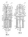
- FIG. 3is a cross-sectional view of the suture locker shown in FIG. 1 , taken along the line 3 - 3 in FIG. 2 .
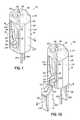
- a suture locker 50 constructed in accordance with a first embodiment of the inventionis utilized to selectively capture one or more tensioning members 54 , 58 ( FIG. 4 ) threaded through the suture locker 50 .
- the tensioning members 54 , 58can take forms other than suture material, such as a cable or any other small diameter, flexible, semi-rigid or rigid material having a suitably high tensile strength for the intended use.
- the embodiments of the inventionare referred to as suture lockers, the invention contemplates that the suture lockers can be used with tensioning members other than sutures.
- the suture locker 50 , and hub 146are directed through the vascular network to the surgical site.
- the tensioning members 54 , 58can be threaded through the passageways 118 , 86 , 162 and are normally free to move with negligible resistance from the pin 66 as depicted in FIG. 4 .
- the pin 66 of the suture locker 50is held initially in a latent position, i.e. the short segment 110 .
- the suture locker 50is then pushed through the vascular network by the physician using a distally directed force applied to the catheter body 158 .
- the catheter assembly 154delivers the suture locker 50 to the surgical site, which can be confirmed by the in vivo visualization of a fluoroscopic marker on the suture locker 50 or a radio-opaque material used in constructing the base member 74 .
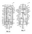
- each retraction member 196includes a transverse opening 218 for receiving a retaining pin 184 .
- the retaining pin 184prevents the movement of the retraction members 196 from the locker body 62 .
- the elongated portion 200 of each retraction member 196extends proximally to outside the patient's body, allowing the physician to manipulate the suture locker 190 , in vivo, at the surgical site.
- the retaining pins 184each extend within peripheral passageways 222 , 226 within the sidewalls 94 , 98 of the locker body 62 and through the transverse openings 218 of each retraction member 196 .
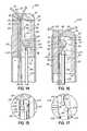
- FIGS. 14-17where yet another embodiment of a suture locker 228 is illustrated and includes an elongated pin 230 that extends proximally from the pin 66 and through the passageway 86 of the base member 74 .
- the elongated pin 230can be a rigid or semi-rigid rod construction, such as stainless steel, and includes an alignment key 234 on the distal end.
- the proximal end of the elongated pin 230extends beyond the proximal aperture 90 and out of the body of the patient. In this way, the physician can remotely manipulate the position of the pin 66 from the latent to the activated position in a manner described below.
- the physicianapplies a distally-directed force against the elongated pin 230 such that the alignment key 234 abuts the central section 134 of the pin 66 and causes the pin to move within the slots 102 , 106 toward the cap 78 .
- the pin 66then follows the contour of the slots 102 , 106 as it moves from a latent position, as shown in FIG. 14 , to an activated position as shown in FIG. 16 .
- the alignment keys 234 , 238extend beyond the narrow sheath 242 and are free to move laterally with respect to one another. This greater freedom allows the interlocking balls to become disengaged, as shown in FIGS. 16 and 17 , and allows the physician to retract the elongated pin 230 from the locker body 62 .
Landscapes
- Health & Medical Sciences (AREA)
- Life Sciences & Earth Sciences (AREA)
- Surgery (AREA)
- Heart & Thoracic Surgery (AREA)
- Engineering & Computer Science (AREA)
- Biomedical Technology (AREA)
- Nuclear Medicine, Radiotherapy & Molecular Imaging (AREA)
- Medical Informatics (AREA)
- Molecular Biology (AREA)
- Animal Behavior & Ethology (AREA)
- General Health & Medical Sciences (AREA)
- Public Health (AREA)
- Veterinary Medicine (AREA)
- Surgical Instruments (AREA)
Abstract
Description
Claims (16)
Priority Applications (1)
| Application Number | Priority Date | Filing Date | Title |
|---|---|---|---|
| US12/394,528US9131939B1 (en) | 2008-02-27 | 2009-02-27 | Device for percutaneously delivering a cardiac implant through the application of direct actuation forces external to the body |
Applications Claiming Priority (2)
| Application Number | Priority Date | Filing Date | Title |
|---|---|---|---|
| US3179808P | 2008-02-27 | 2008-02-27 | |
| US12/394,528US9131939B1 (en) | 2008-02-27 | 2009-02-27 | Device for percutaneously delivering a cardiac implant through the application of direct actuation forces external to the body |
Publications (1)
| Publication Number | Publication Date |
|---|---|
| US9131939B1true US9131939B1 (en) | 2015-09-15 |
Family
ID=54063384
Family Applications (1)
| Application Number | Title | Priority Date | Filing Date |
|---|---|---|---|
| US12/394,528Active2031-08-04US9131939B1 (en) | 2008-02-27 | 2009-02-27 | Device for percutaneously delivering a cardiac implant through the application of direct actuation forces external to the body |
Country Status (1)
| Country | Link |
|---|---|
| US (1) | US9131939B1 (en) |
Cited By (21)
| Publication number | Priority date | Publication date | Assignee | Title |
|---|---|---|---|---|
| US9693865B2 (en) | 2013-01-09 | 2017-07-04 | 4 Tech Inc. | Soft tissue depth-finding tool |
| US9801720B2 (en) | 2014-06-19 | 2017-10-31 | 4Tech Inc. | Cardiac tissue cinching |
| US9907681B2 (en) | 2013-03-14 | 2018-03-06 | 4Tech Inc. | Stent with tether interface |
| US9907547B2 (en) | 2014-12-02 | 2018-03-06 | 4Tech Inc. | Off-center tissue anchors |
| US10022114B2 (en) | 2013-10-30 | 2018-07-17 | 4Tech Inc. | Percutaneous tether locking |
| US10052095B2 (en) | 2013-10-30 | 2018-08-21 | 4Tech Inc. | Multiple anchoring-point tension system |
| US10058323B2 (en) | 2010-01-22 | 2018-08-28 | 4 Tech Inc. | Tricuspid valve repair using tension |
| US10238491B2 (en) | 2010-01-22 | 2019-03-26 | 4Tech Inc. | Tricuspid valve repair using tension |
| US10405978B2 (en) | 2010-01-22 | 2019-09-10 | 4Tech Inc. | Tricuspid valve repair using tension |
| US10543090B2 (en) | 2016-12-30 | 2020-01-28 | Pipeline Medical Technologies, Inc. | Neo chordae tendinae deployment system |
| US10667910B2 (en) | 2016-12-30 | 2020-06-02 | Pipeline Medical Technologies, Inc. | Method and apparatus for transvascular implantation of neo chordae tendinae |
| US10925731B2 (en) | 2016-12-30 | 2021-02-23 | Pipeline Medical Technologies, Inc. | Method and apparatus for transvascular implantation of neo chordae tendinae |
| US11026791B2 (en) | 2018-03-20 | 2021-06-08 | Medtronic Vascular, Inc. | Flexible canopy valve repair systems and methods of use |
| EP3764919A4 (en)* | 2018-03-12 | 2022-01-19 | Pipeline Medical Technologies, Inc. | METHOD AND APPARATUS FOR REPAIRING MITRAL VALVE STRINGS |
| US11285003B2 (en) | 2018-03-20 | 2022-03-29 | Medtronic Vascular, Inc. | Prolapse prevention device and methods of use thereof |
| US20220225979A1 (en)* | 2021-01-21 | 2022-07-21 | Neochord, Inc. | Minimally invasive heart valve repair in a beating heart |
| US11395648B2 (en)* | 2012-09-29 | 2022-07-26 | Edwards Lifesciences Corporation | Plication lock delivery system and method of use thereof |
| US11696828B2 (en) | 2016-12-30 | 2023-07-11 | Pipeline Medical Technologies, Inc. | Method and apparatus for mitral valve chord repair |
| EP4129236A4 (en)* | 2020-05-29 | 2023-09-06 | Creative Medtech (Suzhou) Co., Ltd. | SUTURE LOCKING DEVICE AND APPARATUS FOR IMPLANTING SUTURE LOCKING DEVICE |
| US12318296B2 (en) | 2015-12-30 | 2025-06-03 | Pipeline Medical Technologies, Inc. | Mitral leaflet tethering |
| US12350155B2 (en) | 2020-06-17 | 2025-07-08 | Pipeline Medical Technologies, Inc. | Method and apparatus for mitral valve chord repair |
Citations (132)
| Publication number | Priority date | Publication date | Assignee | Title |
|---|---|---|---|---|
| US1518523A (en) | 1924-01-16 | 1924-12-09 | Kubik Andrew | Clothesline fastener |
| US2245030A (en)* | 1940-07-19 | 1941-06-10 | Gottesfeld Benjamin Harvey | Tubing clamp for intravenous operations |
| US2595511A (en)* | 1948-10-29 | 1952-05-06 | Cutter Lab | Pinch valve |
| US2866340A (en)* | 1955-09-06 | 1958-12-30 | Goldberg Moshe | Device for taking samples of liquid for testing |
| US3135259A (en) | 1963-12-12 | 1964-06-02 | Sterilon Corp | Infusion flow control valve |
| US3215395A (en)* | 1962-06-25 | 1965-11-02 | Gorbar Nettie | Regulating clamp for flexible tubes |
| US3572804A (en)* | 1969-04-16 | 1971-03-30 | Robert C Nims | Variable length line fastening device |
| US3628221A (en) | 1968-05-02 | 1971-12-21 | Max Pasbrig | Device for clamping and tightening cables and the like |
| US3685787A (en)* | 1969-09-08 | 1972-08-22 | Marvin Adelberg | Apparatus for regulating fluid flow through plastic tubing |
| US3766610A (en) | 1971-06-29 | 1973-10-23 | A Thorsbakken | Wedge locking device |
| US3900184A (en)* | 1973-12-13 | 1975-08-19 | Burron Medical Prod Inc | Roller clamp for tubing |
| US3952377A (en) | 1974-01-25 | 1976-04-27 | Juan Coll Morell | Conical wedges for gripping multi-ply rope or cable |
| US3960149A (en)* | 1974-11-13 | 1976-06-01 | Abbott Laboratories | Flow control device |
| US3984081A (en)* | 1974-10-25 | 1976-10-05 | The Raymond Lee Organization, Inc. | Medical device for controlling flow of intravenous solutions |
| US4065093A (en)* | 1976-05-24 | 1977-12-27 | Baxter Travenol Laboratories, Inc. | Flow control device |
| US4148224A (en) | 1977-07-27 | 1979-04-10 | H. Koch & Sons Division, Gulf & Western Manufacturing Company | Belt adjuster box style |
| US4406440A (en)* | 1980-03-25 | 1983-09-27 | Baxter Travenol Laboratories, Inc. | Flow regulating device |
| US4455717A (en) | 1982-09-22 | 1984-06-26 | Gray Robert C | Rope clamping device |
| US4719671A (en) | 1984-11-08 | 1988-01-19 | Canon Kabushiki Kaisha | Strap connector |
| US4727628A (en) | 1985-10-24 | 1988-03-01 | Rudholm & Co. I Boras Ab | Strap buckle with self-locking function |
| US4750492A (en)* | 1985-02-27 | 1988-06-14 | Richards Medical Company | Absorbable suture apparatus, method and installer |
| US5078731A (en) | 1990-06-05 | 1992-01-07 | Hayhurst John O | Suture clip |
| US5123914A (en) | 1986-05-19 | 1992-06-23 | Cook Incorporated | Visceral anchor for visceral wall mobilization |
| US5137517A (en)* | 1989-11-28 | 1992-08-11 | Scimed Life Systems, Inc. | Device and method for gripping medical shaft |
| US5258015A (en) | 1991-05-03 | 1993-11-02 | American Cyanamid Company | Locking filament caps |
| US5356412A (en) | 1992-10-09 | 1994-10-18 | United States Surgical Corporation | Sternum buckle with rotational engagement and method of closure |
| US5366458A (en) | 1990-12-13 | 1994-11-22 | United States Surgical Corporation | Latchless surgical clip |
| US5368599A (en) | 1992-10-08 | 1994-11-29 | United States Surgical Corporation | Surgical fastening apparatus with suture array |
| US5369849A (en) | 1993-03-25 | 1994-12-06 | Fargo Mfg. Company, Inc. | Cable gripping unit with spring biased jaw segments |
| US5372146A (en) | 1990-11-06 | 1994-12-13 | Branch; Thomas P. | Method and apparatus for re-approximating tissue |
| US5383905A (en) | 1992-10-09 | 1995-01-24 | United States Surgical Corporation | Suture loop locking device |
| US5391173A (en) | 1994-02-10 | 1995-02-21 | Wilk; Peter J. | Laparoscopic suturing technique and associated device |
| US5403331A (en) | 1993-03-12 | 1995-04-04 | United States Surgical Corporation | Looped suture ligating device containing a heat-shrinkable element |
| US5413585A (en) | 1992-12-22 | 1995-05-09 | Pagedas; Anthony C. | Self locking suture lock |
| US5464427A (en) | 1994-10-04 | 1995-11-07 | Synthes (U.S.A.) | Expanding suture anchor |
| US5486197A (en) | 1994-03-24 | 1996-01-23 | Ethicon, Inc. | Two-piece suture anchor with barbs |
| US5562689A (en) | 1993-08-20 | 1996-10-08 | United States Surgical Corporation | Apparatus and method for applying and adjusting an anchoring device |
| US5584835A (en)* | 1993-10-18 | 1996-12-17 | Greenfield; Jon B. | Soft tissue to bone fixation device and method |
| US5584861A (en) | 1992-09-04 | 1996-12-17 | University College London | Device for use in securing a thread |
| US5630824A (en) | 1994-06-01 | 1997-05-20 | Innovasive Devices, Inc. | Suture attachment device |
| US5643295A (en) | 1994-12-29 | 1997-07-01 | Yoon; Inbae | Methods and apparatus for suturing tissue |
| US5669935A (en) | 1995-07-28 | 1997-09-23 | Ethicon, Inc. | One-way suture retaining device for braided sutures |
| US5681351A (en) | 1994-10-21 | 1997-10-28 | Ethicon, Inc. | Suture clip suitable for use on monofilament sutures |
| US5695505A (en) | 1995-03-09 | 1997-12-09 | Yoon; Inbae | Multifunctional spring clips and cartridges and applicators therefor |
| US5702397A (en)* | 1996-02-20 | 1997-12-30 | Medicinelodge, Inc. | Ligament bone anchor and method for its use |
| US5725539A (en) | 1993-12-01 | 1998-03-10 | Klinikum Der Albert-Ludwigs-Universitat Freiburg | Surgical instrument used to clamp a vessel or the like |
| US5725556A (en) | 1995-12-15 | 1998-03-10 | M & R Medical, Inc. | Suture locking apparatus |
| US5735877A (en) | 1996-02-28 | 1998-04-07 | Pagedas; Anthony C. | Self locking suture lock |
| US5810851A (en) | 1996-03-05 | 1998-09-22 | Yoon; Inbae | Suture spring device |
| US5814051A (en)* | 1997-06-06 | 1998-09-29 | Mitex Surgical Products, Inc. | Suture anchor insertion system |
| US5861004A (en) | 1991-11-08 | 1999-01-19 | Kensey Nash Corporation | Hemostatic puncture closure system including closure locking means and method of use |
| US5895391A (en)* | 1996-09-27 | 1999-04-20 | Target Therapeutics, Inc. | Ball lock joint and introducer for vaso-occlusive member |
| US5895393A (en) | 1997-09-23 | 1999-04-20 | Pagedas; Anthony C. | Suture lock holder |
| US5899921A (en) | 1997-07-25 | 1999-05-04 | Innovasive Devices, Inc. | Connector device and method for surgically joining and securing flexible tissue repair members |
| US5957953A (en)* | 1996-02-16 | 1999-09-28 | Smith & Nephew, Inc. | Expandable suture anchor |
| US5964769A (en) | 1997-08-26 | 1999-10-12 | Spinal Concepts, Inc. | Surgical cable system and method |
| US5972001A (en) | 1996-11-25 | 1999-10-26 | Yoon; Inbae | Method of ligating anatomical tissue with a suture spring device |
| US6010525A (en) | 1997-08-01 | 2000-01-04 | Peter M. Bonutti | Method and apparatus for securing a suture |
| US6015428A (en) | 1997-06-03 | 2000-01-18 | Anthony C. Pagedas | Integrally formed suture and suture lock |
| US6066160A (en) | 1998-11-23 | 2000-05-23 | Quickie Llc | Passive knotless suture terminator for use in minimally invasive surgery and to facilitate standard tissue securing |
| US6086608A (en) | 1996-02-22 | 2000-07-11 | Smith & Nephew, Inc. | Suture collet |
| US6099553A (en) | 1998-05-21 | 2000-08-08 | Applied Medical Resources Corporation | Suture clinch |
| US6126677A (en) | 1996-05-20 | 2000-10-03 | Noknots Group Inc. | Suture fastener and instrument |
| US6159234A (en) | 1997-08-01 | 2000-12-12 | Peter M. Bonutti | Method and apparatus for securing a suture |
| US6200329B1 (en) | 1998-08-31 | 2001-03-13 | Smith & Nephew, Inc. | Suture collet |
| US6290711B1 (en) | 1999-08-13 | 2001-09-18 | Innovasive Devices, Inc. | Connector device and method for surgically joining and securing flexible tissue repair members |
| US6293961B2 (en) | 1998-12-30 | 2001-09-25 | Ethicon, Inc. | Suture locking device |
| US6306159B1 (en) | 1998-12-23 | 2001-10-23 | Depuy Orthopaedics, Inc. | Meniscal repair device |
| US6319269B1 (en) | 1995-04-21 | 2001-11-20 | Lehmann K. Li | Fixation device and method for installing same |
| US6368343B1 (en) | 2000-03-13 | 2002-04-09 | Peter M. Bonutti | Method of using ultrasonic vibration to secure body tissue |
| US6409743B1 (en) | 1998-07-08 | 2002-06-25 | Axya Medical, Inc. | Devices and methods for securing sutures and ligatures without knots |
| US6423088B1 (en) | 1998-07-08 | 2002-07-23 | Axya Medical, Inc. | Sharp edged device for closing wounds without knots |
| US20020111653A1 (en)* | 2001-02-12 | 2002-08-15 | Opus Medical, Inc. | Method and apparatus for attaching connective tissues to bone using a knotless suture anchoring device |
| US6475230B1 (en) | 1997-08-01 | 2002-11-05 | Peter M. Bonutti | Method and apparatus for securing a suture |
| US6517556B1 (en) | 1999-10-28 | 2003-02-11 | Niti Alloys Technologies Ltd. | Shape memory alloy clip and method of use thereof |
| US6524328B2 (en) | 2001-04-12 | 2003-02-25 | Scion International, Inc. | Suture lock, lock applicator and method therefor |
| US6527794B1 (en) | 1999-08-10 | 2003-03-04 | Ethicon, Inc. | Self-locking suture anchor |
| US6575987B2 (en) | 1997-02-13 | 2003-06-10 | Scimed Life Systems, Inc. | Quick connect bone suture fastener |
| US6599311B1 (en) | 1998-06-05 | 2003-07-29 | Broncus Technologies, Inc. | Method and assembly for lung volume reduction |
| US20030167062A1 (en) | 2003-03-13 | 2003-09-04 | Gambale Richard A | Suture clips,delivery devices and methods |
| US20030195562A1 (en) | 2002-04-12 | 2003-10-16 | Ethicon, Inc. | Suture anchoring and tensioning device and method for using same |
| US20030195563A1 (en) | 2000-08-30 | 2003-10-16 | Opus Medical, Inc. | Method and apparatus for attaching connective tissues to bone using a knotless suture anchoring device |
| US20030229377A1 (en) | 2002-06-10 | 2003-12-11 | Thomas Tong | Tube and rod suture clamping system |
| US20040024420A1 (en) | 1996-09-13 | 2004-02-05 | Tendon Technology, Ltd. | Apparatus and methods for securing tendons or ligaments to bone |
| US20040098050A1 (en) | 2002-11-19 | 2004-05-20 | Opus Medical, Inc. | Devices and methods for repairing soft tissue |
| US20040133239A1 (en) | 2002-11-15 | 2004-07-08 | Wanis Singhatat | Knotless suture anchor |
| US20040147958A1 (en) | 2002-12-11 | 2004-07-29 | Usgi Medical | Apparatus and methods for forming and securing gastrointestinal tissue folds |
| US6770076B2 (en)* | 2001-02-12 | 2004-08-03 | Opus Medical, Inc. | Method and apparatus for attaching connective tissues to bone using a knotless suture anchoring device |
| US20040162568A1 (en) | 1999-06-25 | 2004-08-19 | Usgi Medical | Apparatus and methods for forming and securing gastrointestinal tissue folds |
| US20040193191A1 (en) | 2003-02-06 | 2004-09-30 | Guided Delivery Systems, Inc. | Devices and methods for heart valve repair |
| US20040220616A1 (en) | 2000-03-13 | 2004-11-04 | Bonutti Peter M. | Method and device for securing body tissue |
| US6814742B2 (en) | 2000-10-16 | 2004-11-09 | Olympus Corporation | Physiological tissue clipping apparatus, clipping method and clip unit mounting method |
| US20040230223A1 (en) | 2000-03-13 | 2004-11-18 | Bonutti Peter M. | Method and device for securing body tissue |
| US20040236374A1 (en) | 2000-03-13 | 2004-11-25 | Bonutti Peter M. | Method and device for securing body tissue |
| US20040243227A1 (en) | 2002-06-13 | 2004-12-02 | Guided Delivery Systems, Inc. | Delivery devices and methods for heart valve repair |
| US20040260344A1 (en) | 2003-05-07 | 2004-12-23 | Anpa Medical, Inc. | Suture lock |
| US20050004602A1 (en) | 2003-07-02 | 2005-01-06 | Applied Medical Resources Corporation | Interlocking suture clinch |
| US20050033319A1 (en) | 2003-05-16 | 2005-02-10 | Gambale Richard A. | Single intubation, multi-stitch endoscopic suturing system |
| US6855157B2 (en) | 2002-02-04 | 2005-02-15 | Arthrocare Corporation | Method and apparatus for attaching connective tissues to bone using a knotless suture anchoring device |
| US20050055087A1 (en) | 2003-09-04 | 2005-03-10 | Guided Delivery Systems, Inc. | Devices and methods for cardiac annulus stabilization and treatment |
| US20050055052A1 (en) | 2003-09-10 | 2005-03-10 | Linvatec Corporation | Knotless suture anchor |
| US20050085855A1 (en) | 2003-10-17 | 2005-04-21 | Forsberg Andrew T. | Automatic suture locking device |
| US20050096699A1 (en) | 2003-11-05 | 2005-05-05 | Applied Medical Resources Corporation | Suture securing device and method |
| US20050119675A1 (en) | 2003-10-24 | 2005-06-02 | Adams Daniel O. | Patent foramen ovale closure system |
| US20050216059A1 (en) | 2002-09-05 | 2005-09-29 | Bonutti Peter M | Method and apparatus for securing a suture |
| US20050222489A1 (en) | 2003-10-01 | 2005-10-06 | Ample Medical, Inc. | Devices, systems, and methods for reshaping a heart valve annulus, including the use of a bridge implant |
| US20050228422A1 (en) | 2002-11-26 | 2005-10-13 | Ample Medical, Inc. | Devices, systems, and methods for reshaping a heart valve annulus, including the use of magnetic tools |
| US20050251157A1 (en) | 2004-05-07 | 2005-11-10 | Usgi Medical Inc. | Apparatus and methods for positioning and securing anchors |
| US20050251208A1 (en) | 2004-05-07 | 2005-11-10 | Usgi Medical Inc. | Linear anchors for anchoring to tissue |
| US20050251202A1 (en) | 2004-05-07 | 2005-11-10 | Usgi Medical Inc. | Interlocking tissue anchor apparatus and methods |
| US20050251209A1 (en) | 2004-05-07 | 2005-11-10 | Usgi Medical Inc. | Apparatus and methods for positioning and securing anchors |
| US20050251210A1 (en) | 2004-05-07 | 2005-11-10 | Usgi Medical Inc. | Methods and apparatus for grasping and cinching tissue anchors |
| US6972027B2 (en) | 2002-06-26 | 2005-12-06 | Stryker Endoscopy | Soft tissue repair system |
| US20050288709A1 (en) | 2003-06-11 | 2005-12-29 | Fallin T W | Adjustable line locks and methods |
| US20050288711A1 (en) | 2003-06-11 | 2005-12-29 | Fallin T W | Line lock suture attachment systems and methods |
| US20050288710A1 (en) | 2003-06-11 | 2005-12-29 | Fallin T W | Line lock threading systems and methods |
| US20060004410A1 (en) | 2004-05-14 | 2006-01-05 | Nobis Rudolph H | Suture locking and cutting devices and methods |
| US20060004409A1 (en) | 2004-05-14 | 2006-01-05 | Nobis Rudolph H | Devices for locking and/or cutting a suture |
| US6986775B2 (en) | 2002-06-13 | 2006-01-17 | Guided Delivery Systems, Inc. | Devices and methods for heart valve repair |
| US6997189B2 (en) | 1998-06-05 | 2006-02-14 | Broncus Technologies, Inc. | Method for lung volume reduction |
| US20060058844A1 (en) | 2004-09-13 | 2006-03-16 | St. Jude Medical Puerto Rico B.V. | Vascular sealing device with locking system |
| US7033379B2 (en) | 2001-06-08 | 2006-04-25 | Incisive Surgical, Inc. | Suture lock having non-through bore capture zone |
| US20060106422A1 (en)* | 2004-11-16 | 2006-05-18 | Del Rio Eddy W | Anchor/suture used for medical procedures |
| US20060122633A1 (en) | 2002-06-13 | 2006-06-08 | John To | Methods and devices for termination |
| US7094251B2 (en) | 2002-08-27 | 2006-08-22 | Marctec, Llc. | Apparatus and method for securing a suture |
| US7094240B2 (en) | 2003-01-10 | 2006-08-22 | Sdgi Holdings, Inc. | Flexible member tensioning instruments and methods |
| US7101395B2 (en) | 2002-06-12 | 2006-09-05 | Mitral Interventions, Inc. | Method and apparatus for tissue connection |
| US20070276437A1 (en)* | 2006-05-25 | 2007-11-29 | Mitralign, Inc. | Lockers for surgical tensioning members and methods of using the same to secure surgical tensioning members |
| US20080228165A1 (en) | 2007-03-13 | 2008-09-18 | Mitralign, Inc. | Systems and methods for introducing elements into tissue |
| US7517357B2 (en)* | 2003-01-09 | 2009-04-14 | Linvatec Biomaterials | Knotless suture anchor |
| US7875056B2 (en)* | 2005-07-22 | 2011-01-25 | Anpa Medical, Inc. | Wedge operated retainer device and methods |
| US20120109155A1 (en) | 2010-10-27 | 2012-05-03 | Mitralign, Inc. | Hand operated device for controlled deployment of a tissue anchor and method of using the same |
- 2009
- 2009-02-27USUS12/394,528patent/US9131939B1/enactiveActive
Patent Citations (165)
| Publication number | Priority date | Publication date | Assignee | Title |
|---|---|---|---|---|
| US1518523A (en) | 1924-01-16 | 1924-12-09 | Kubik Andrew | Clothesline fastener |
| US2245030A (en)* | 1940-07-19 | 1941-06-10 | Gottesfeld Benjamin Harvey | Tubing clamp for intravenous operations |
| US2595511A (en)* | 1948-10-29 | 1952-05-06 | Cutter Lab | Pinch valve |
| US2866340A (en)* | 1955-09-06 | 1958-12-30 | Goldberg Moshe | Device for taking samples of liquid for testing |
| US3215395A (en)* | 1962-06-25 | 1965-11-02 | Gorbar Nettie | Regulating clamp for flexible tubes |
| US3135259A (en) | 1963-12-12 | 1964-06-02 | Sterilon Corp | Infusion flow control valve |
| US3628221A (en) | 1968-05-02 | 1971-12-21 | Max Pasbrig | Device for clamping and tightening cables and the like |
| US3572804A (en)* | 1969-04-16 | 1971-03-30 | Robert C Nims | Variable length line fastening device |
| US3685787A (en)* | 1969-09-08 | 1972-08-22 | Marvin Adelberg | Apparatus for regulating fluid flow through plastic tubing |
| US3766610A (en) | 1971-06-29 | 1973-10-23 | A Thorsbakken | Wedge locking device |
| US3900184A (en)* | 1973-12-13 | 1975-08-19 | Burron Medical Prod Inc | Roller clamp for tubing |
| US3952377A (en) | 1974-01-25 | 1976-04-27 | Juan Coll Morell | Conical wedges for gripping multi-ply rope or cable |
| US3984081A (en)* | 1974-10-25 | 1976-10-05 | The Raymond Lee Organization, Inc. | Medical device for controlling flow of intravenous solutions |
| US3960149A (en)* | 1974-11-13 | 1976-06-01 | Abbott Laboratories | Flow control device |
| US4065093A (en)* | 1976-05-24 | 1977-12-27 | Baxter Travenol Laboratories, Inc. | Flow control device |
| US4148224A (en) | 1977-07-27 | 1979-04-10 | H. Koch & Sons Division, Gulf & Western Manufacturing Company | Belt adjuster box style |
| US4406440A (en)* | 1980-03-25 | 1983-09-27 | Baxter Travenol Laboratories, Inc. | Flow regulating device |
| US4455717A (en) | 1982-09-22 | 1984-06-26 | Gray Robert C | Rope clamping device |
| US4719671A (en) | 1984-11-08 | 1988-01-19 | Canon Kabushiki Kaisha | Strap connector |
| US4750492A (en)* | 1985-02-27 | 1988-06-14 | Richards Medical Company | Absorbable suture apparatus, method and installer |
| US4727628A (en) | 1985-10-24 | 1988-03-01 | Rudholm & Co. I Boras Ab | Strap buckle with self-locking function |
| US5123914A (en) | 1986-05-19 | 1992-06-23 | Cook Incorporated | Visceral anchor for visceral wall mobilization |
| US5137517A (en)* | 1989-11-28 | 1992-08-11 | Scimed Life Systems, Inc. | Device and method for gripping medical shaft |
| US5078731A (en) | 1990-06-05 | 1992-01-07 | Hayhurst John O | Suture clip |
| US5372146A (en) | 1990-11-06 | 1994-12-13 | Branch; Thomas P. | Method and apparatus for re-approximating tissue |
| US5366458A (en) | 1990-12-13 | 1994-11-22 | United States Surgical Corporation | Latchless surgical clip |
| US5258015A (en) | 1991-05-03 | 1993-11-02 | American Cyanamid Company | Locking filament caps |
| US5861004A (en) | 1991-11-08 | 1999-01-19 | Kensey Nash Corporation | Hemostatic puncture closure system including closure locking means and method of use |
| US5584861A (en) | 1992-09-04 | 1996-12-17 | University College London | Device for use in securing a thread |
| US5368599A (en) | 1992-10-08 | 1994-11-29 | United States Surgical Corporation | Surgical fastening apparatus with suture array |
| US5356412A (en) | 1992-10-09 | 1994-10-18 | United States Surgical Corporation | Sternum buckle with rotational engagement and method of closure |
| US5383905A (en) | 1992-10-09 | 1995-01-24 | United States Surgical Corporation | Suture loop locking device |
| US5413585A (en) | 1992-12-22 | 1995-05-09 | Pagedas; Anthony C. | Self locking suture lock |
| US5403331A (en) | 1993-03-12 | 1995-04-04 | United States Surgical Corporation | Looped suture ligating device containing a heat-shrinkable element |
| US5369849A (en) | 1993-03-25 | 1994-12-06 | Fargo Mfg. Company, Inc. | Cable gripping unit with spring biased jaw segments |
| US5562689A (en) | 1993-08-20 | 1996-10-08 | United States Surgical Corporation | Apparatus and method for applying and adjusting an anchoring device |
| US5584835A (en)* | 1993-10-18 | 1996-12-17 | Greenfield; Jon B. | Soft tissue to bone fixation device and method |
| US5725539A (en) | 1993-12-01 | 1998-03-10 | Klinikum Der Albert-Ludwigs-Universitat Freiburg | Surgical instrument used to clamp a vessel or the like |
| US5391173A (en) | 1994-02-10 | 1995-02-21 | Wilk; Peter J. | Laparoscopic suturing technique and associated device |
| US5626590A (en) | 1994-02-10 | 1997-05-06 | Wilk; Peter J. | Laparoscopic suturing technique and associated device |
| US5486197A (en) | 1994-03-24 | 1996-01-23 | Ethicon, Inc. | Two-piece suture anchor with barbs |
| US5630824A (en) | 1994-06-01 | 1997-05-20 | Innovasive Devices, Inc. | Suture attachment device |
| US5464427A (en) | 1994-10-04 | 1995-11-07 | Synthes (U.S.A.) | Expanding suture anchor |
| US5681351A (en) | 1994-10-21 | 1997-10-28 | Ethicon, Inc. | Suture clip suitable for use on monofilament sutures |
| US5643295A (en) | 1994-12-29 | 1997-07-01 | Yoon; Inbae | Methods and apparatus for suturing tissue |
| US5695505A (en) | 1995-03-09 | 1997-12-09 | Yoon; Inbae | Multifunctional spring clips and cartridges and applicators therefor |
| US5849019A (en) | 1995-03-09 | 1998-12-15 | Yoon; Inbae | Multifunctional spring clips and cartridges and applications therefor |
| US6319269B1 (en) | 1995-04-21 | 2001-11-20 | Lehmann K. Li | Fixation device and method for installing same |
| US5669935A (en) | 1995-07-28 | 1997-09-23 | Ethicon, Inc. | One-way suture retaining device for braided sutures |
| US5725556A (en) | 1995-12-15 | 1998-03-10 | M & R Medical, Inc. | Suture locking apparatus |
| US5957953A (en)* | 1996-02-16 | 1999-09-28 | Smith & Nephew, Inc. | Expandable suture anchor |
| US5702397A (en)* | 1996-02-20 | 1997-12-30 | Medicinelodge, Inc. | Ligament bone anchor and method for its use |
| US6086608A (en) | 1996-02-22 | 2000-07-11 | Smith & Nephew, Inc. | Suture collet |
| US5735877A (en) | 1996-02-28 | 1998-04-07 | Pagedas; Anthony C. | Self locking suture lock |
| US5741301A (en) | 1996-02-28 | 1998-04-21 | Pagedas; Anthony C. | Self locking suture lock |
| US5810851A (en) | 1996-03-05 | 1998-09-22 | Yoon; Inbae | Suture spring device |
| US6126677A (en) | 1996-05-20 | 2000-10-03 | Noknots Group Inc. | Suture fastener and instrument |
| US20040024420A1 (en) | 1996-09-13 | 2004-02-05 | Tendon Technology, Ltd. | Apparatus and methods for securing tendons or ligaments to bone |
| US5895391A (en)* | 1996-09-27 | 1999-04-20 | Target Therapeutics, Inc. | Ball lock joint and introducer for vaso-occlusive member |
| US5972001A (en) | 1996-11-25 | 1999-10-26 | Yoon; Inbae | Method of ligating anatomical tissue with a suture spring device |
| US6575987B2 (en) | 1997-02-13 | 2003-06-10 | Scimed Life Systems, Inc. | Quick connect bone suture fastener |
| US6015428A (en) | 1997-06-03 | 2000-01-18 | Anthony C. Pagedas | Integrally formed suture and suture lock |
| US5814051A (en)* | 1997-06-06 | 1998-09-29 | Mitex Surgical Products, Inc. | Suture anchor insertion system |
| US5899921A (en) | 1997-07-25 | 1999-05-04 | Innovasive Devices, Inc. | Connector device and method for surgically joining and securing flexible tissue repair members |
| US5902321A (en) | 1997-07-25 | 1999-05-11 | Innovasive Devices, Inc. | Device and method for delivering a connector for surgically joining and securing flexible tissue repair members |
| US6475230B1 (en) | 1997-08-01 | 2002-11-05 | Peter M. Bonutti | Method and apparatus for securing a suture |
| US20050267534A1 (en) | 1997-08-01 | 2005-12-01 | Bonutti Peter M | Surgical fastener |
| US6159234A (en) | 1997-08-01 | 2000-12-12 | Peter M. Bonutti | Method and apparatus for securing a suture |
| US7147652B2 (en) | 1997-08-01 | 2006-12-12 | Bonutti Ip, Llc | Method and apparatus for securing a suture |
| US6231592B1 (en) | 1997-08-01 | 2001-05-15 | Peter M. Bonutti | Method and apparatus for securing a suture |
| US6932835B2 (en) | 1997-08-01 | 2005-08-23 | Bonutti Ip, Llc | Suture securing tool |
| US7048755B2 (en) | 1997-08-01 | 2006-05-23 | Bonutti Peter M | Method and apparatus for securing a suture |
| US6569187B1 (en) | 1997-08-01 | 2003-05-27 | Peter M. Bonutti | Method and apparatus for securing a suture |
| US6010525A (en) | 1997-08-01 | 2000-01-04 | Peter M. Bonutti | Method and apparatus for securing a suture |
| US6468293B2 (en) | 1997-08-01 | 2002-10-22 | Peter M. Bonutti | Method and apparatus for securing a suture |
| US5964769A (en) | 1997-08-26 | 1999-10-12 | Spinal Concepts, Inc. | Surgical cable system and method |
| US6682533B1 (en) | 1997-08-26 | 2004-01-27 | Spinal Concepts, Inc. | Surgical cable system and method |
| US6391030B1 (en) | 1997-08-26 | 2002-05-21 | Spinal Concepts, Inc. | Surgical cable system and method |
| US5895393A (en) | 1997-09-23 | 1999-04-20 | Pagedas; Anthony C. | Suture lock holder |
| US6099553A (en) | 1998-05-21 | 2000-08-08 | Applied Medical Resources Corporation | Suture clinch |
| US6599311B1 (en) | 1998-06-05 | 2003-07-29 | Broncus Technologies, Inc. | Method and assembly for lung volume reduction |
| US6997189B2 (en) | 1998-06-05 | 2006-02-14 | Broncus Technologies, Inc. | Method for lung volume reduction |
| US6409743B1 (en) | 1998-07-08 | 2002-06-25 | Axya Medical, Inc. | Devices and methods for securing sutures and ligatures without knots |
| US6423088B1 (en) | 1998-07-08 | 2002-07-23 | Axya Medical, Inc. | Sharp edged device for closing wounds without knots |
| US6200329B1 (en) | 1998-08-31 | 2001-03-13 | Smith & Nephew, Inc. | Suture collet |
| US6066160A (en) | 1998-11-23 | 2000-05-23 | Quickie Llc | Passive knotless suture terminator for use in minimally invasive surgery and to facilitate standard tissue securing |
| US6306159B1 (en) | 1998-12-23 | 2001-10-23 | Depuy Orthopaedics, Inc. | Meniscal repair device |
| US6293961B2 (en) | 1998-12-30 | 2001-09-25 | Ethicon, Inc. | Suture locking device |
| US7033380B2 (en) | 1998-12-30 | 2006-04-25 | Ethicon, Inc. | Suture locking device |
| US6319271B1 (en) | 1998-12-30 | 2001-11-20 | Depuy Orthopaedics, Inc. | Suture locking device |
| US20040153103A1 (en) | 1998-12-30 | 2004-08-05 | Schwartz Herbert E. | Soft tissue locking device |
| US6432123B2 (en) | 1998-12-30 | 2002-08-13 | Ethicon, Inc. | Suture locking device |
| US20040225305A1 (en) | 1999-06-25 | 2004-11-11 | Usgi Medical | Apparatus and methods for forming and securing gastrointestinal tissue folds |
| US20040225183A1 (en) | 1999-06-25 | 2004-11-11 | Usgi Medical | Apparatus and methods for forming and securing gastrointestinal tissue folds |
| US20040162568A1 (en) | 1999-06-25 | 2004-08-19 | Usgi Medical | Apparatus and methods for forming and securing gastrointestinal tissue folds |
| US20050075653A1 (en) | 1999-06-25 | 2005-04-07 | Usgi Medical Inc. | Apparatus and methods for forming and securing gastrointestinal tissue folds |
| US20050245945A1 (en) | 1999-06-25 | 2005-11-03 | Usgi Medical Inc. | Apparatus and methods for forming and securing gastrointestinal tissue folds |
| US6660023B2 (en) | 1999-08-10 | 2003-12-09 | Ethicon, Inc. | Self-locking suture anchor |
| US6527794B1 (en) | 1999-08-10 | 2003-03-04 | Ethicon, Inc. | Self-locking suture anchor |
| US20050149122A1 (en) | 1999-08-10 | 2005-07-07 | Mcdevitt Dennis | Self-locking suture anchor |
| US7081126B2 (en) | 1999-08-10 | 2006-07-25 | Ethicon, Inc. | Self-locking suture anchor |
| US6290711B1 (en) | 1999-08-13 | 2001-09-18 | Innovasive Devices, Inc. | Connector device and method for surgically joining and securing flexible tissue repair members |
| US6517556B1 (en) | 1999-10-28 | 2003-02-11 | Niti Alloys Technologies Ltd. | Shape memory alloy clip and method of use thereof |
| US20040230223A1 (en) | 2000-03-13 | 2004-11-18 | Bonutti Peter M. | Method and device for securing body tissue |
| US6368343B1 (en) | 2000-03-13 | 2002-04-09 | Peter M. Bonutti | Method of using ultrasonic vibration to secure body tissue |
| US6585750B2 (en) | 2000-03-13 | 2003-07-01 | Bonutti 2003 Trust-A | Method of using ultrasonic vibration to secure body tissue |
| US20040236374A1 (en) | 2000-03-13 | 2004-11-25 | Bonutti Peter M. | Method and device for securing body tissue |
| US20040220616A1 (en) | 2000-03-13 | 2004-11-04 | Bonutti Peter M. | Method and device for securing body tissue |
| US20030195563A1 (en) | 2000-08-30 | 2003-10-16 | Opus Medical, Inc. | Method and apparatus for attaching connective tissues to bone using a knotless suture anchoring device |
| US6814742B2 (en) | 2000-10-16 | 2004-11-09 | Olympus Corporation | Physiological tissue clipping apparatus, clipping method and clip unit mounting method |
| US20050059985A1 (en) | 2000-10-16 | 2005-03-17 | Olympus Corporation | Endoscopic Clip |
| US7083638B2 (en)* | 2001-02-12 | 2006-08-01 | Arthrocare Corporation | Method and apparatus for attaching connective tissues to bone using a knotless suture anchoring device |
| US20020111653A1 (en)* | 2001-02-12 | 2002-08-15 | Opus Medical, Inc. | Method and apparatus for attaching connective tissues to bone using a knotless suture anchoring device |
| US20050277986A1 (en) | 2001-02-12 | 2005-12-15 | Arthrocare Corporation | Knotless suture lock apparatus and method for securing tissue |
| US6770076B2 (en)* | 2001-02-12 | 2004-08-03 | Opus Medical, Inc. | Method and apparatus for attaching connective tissues to bone using a knotless suture anchoring device |
| US6524328B2 (en) | 2001-04-12 | 2003-02-25 | Scion International, Inc. | Suture lock, lock applicator and method therefor |
| US7033379B2 (en) | 2001-06-08 | 2006-04-25 | Incisive Surgical, Inc. | Suture lock having non-through bore capture zone |
| US6855157B2 (en) | 2002-02-04 | 2005-02-15 | Arthrocare Corporation | Method and apparatus for attaching connective tissues to bone using a knotless suture anchoring device |
| US20030195562A1 (en) | 2002-04-12 | 2003-10-16 | Ethicon, Inc. | Suture anchoring and tensioning device and method for using same |
| US20030229377A1 (en) | 2002-06-10 | 2003-12-11 | Thomas Tong | Tube and rod suture clamping system |
| US7101395B2 (en) | 2002-06-12 | 2006-09-05 | Mitral Interventions, Inc. | Method and apparatus for tissue connection |
| US6986775B2 (en) | 2002-06-13 | 2006-01-17 | Guided Delivery Systems, Inc. | Devices and methods for heart valve repair |
| US20040243227A1 (en) | 2002-06-13 | 2004-12-02 | Guided Delivery Systems, Inc. | Delivery devices and methods for heart valve repair |
| US20060122633A1 (en) | 2002-06-13 | 2006-06-08 | John To | Methods and devices for termination |
| US6972027B2 (en) | 2002-06-26 | 2005-12-06 | Stryker Endoscopy | Soft tissue repair system |
| US7094251B2 (en) | 2002-08-27 | 2006-08-22 | Marctec, Llc. | Apparatus and method for securing a suture |
| US20050216059A1 (en) | 2002-09-05 | 2005-09-29 | Bonutti Peter M | Method and apparatus for securing a suture |
| US20040133239A1 (en) | 2002-11-15 | 2004-07-08 | Wanis Singhatat | Knotless suture anchor |
| US20040098050A1 (en) | 2002-11-19 | 2004-05-20 | Opus Medical, Inc. | Devices and methods for repairing soft tissue |
| US20050228422A1 (en) | 2002-11-26 | 2005-10-13 | Ample Medical, Inc. | Devices, systems, and methods for reshaping a heart valve annulus, including the use of magnetic tools |
| US20040147958A1 (en) | 2002-12-11 | 2004-07-29 | Usgi Medical | Apparatus and methods for forming and securing gastrointestinal tissue folds |
| US7517357B2 (en)* | 2003-01-09 | 2009-04-14 | Linvatec Biomaterials | Knotless suture anchor |
| US7094240B2 (en) | 2003-01-10 | 2006-08-22 | Sdgi Holdings, Inc. | Flexible member tensioning instruments and methods |
| US20040193191A1 (en) | 2003-02-06 | 2004-09-30 | Guided Delivery Systems, Inc. | Devices and methods for heart valve repair |
| US20030167062A1 (en) | 2003-03-13 | 2003-09-04 | Gambale Richard A | Suture clips,delivery devices and methods |
| US20040260344A1 (en) | 2003-05-07 | 2004-12-23 | Anpa Medical, Inc. | Suture lock |
| US20050033319A1 (en) | 2003-05-16 | 2005-02-10 | Gambale Richard A. | Single intubation, multi-stitch endoscopic suturing system |
| US20050288711A1 (en) | 2003-06-11 | 2005-12-29 | Fallin T W | Line lock suture attachment systems and methods |
| US20050288710A1 (en) | 2003-06-11 | 2005-12-29 | Fallin T W | Line lock threading systems and methods |
| US20050288709A1 (en) | 2003-06-11 | 2005-12-29 | Fallin T W | Adjustable line locks and methods |
| US20050004602A1 (en) | 2003-07-02 | 2005-01-06 | Applied Medical Resources Corporation | Interlocking suture clinch |
| US20050055087A1 (en) | 2003-09-04 | 2005-03-10 | Guided Delivery Systems, Inc. | Devices and methods for cardiac annulus stabilization and treatment |
| US20050055052A1 (en) | 2003-09-10 | 2005-03-10 | Linvatec Corporation | Knotless suture anchor |
| US20050222489A1 (en) | 2003-10-01 | 2005-10-06 | Ample Medical, Inc. | Devices, systems, and methods for reshaping a heart valve annulus, including the use of a bridge implant |
| US20050222488A1 (en) | 2003-10-01 | 2005-10-06 | Ample Medical, Inc. | Devices, systems, and methods for reshaping a heart valve annulus |
| US20050085855A1 (en) | 2003-10-17 | 2005-04-21 | Forsberg Andrew T. | Automatic suture locking device |
| US20050119675A1 (en) | 2003-10-24 | 2005-06-02 | Adams Daniel O. | Patent foramen ovale closure system |
| US20050096699A1 (en) | 2003-11-05 | 2005-05-05 | Applied Medical Resources Corporation | Suture securing device and method |
| US20050251202A1 (en) | 2004-05-07 | 2005-11-10 | Usgi Medical Inc. | Interlocking tissue anchor apparatus and methods |
| US20050251209A1 (en) | 2004-05-07 | 2005-11-10 | Usgi Medical Inc. | Apparatus and methods for positioning and securing anchors |
| US20050251210A1 (en) | 2004-05-07 | 2005-11-10 | Usgi Medical Inc. | Methods and apparatus for grasping and cinching tissue anchors |
| US20050251206A1 (en) | 2004-05-07 | 2005-11-10 | Usgi Medical Corporation | Apparatus and methods for positioning and securing anchors |
| US20050251208A1 (en) | 2004-05-07 | 2005-11-10 | Usgi Medical Inc. | Linear anchors for anchoring to tissue |
| US20050251157A1 (en) | 2004-05-07 | 2005-11-10 | Usgi Medical Inc. | Apparatus and methods for positioning and securing anchors |
| US20050251207A1 (en) | 2004-05-07 | 2005-11-10 | Usgi Medical Inc. | Apparatus and methods for positioning and securing anchors |
| US20050251205A1 (en) | 2004-05-07 | 2005-11-10 | Usgi Medical Inc. | Apparatus and methods for positioning and securing anchors |
| US20060004409A1 (en) | 2004-05-14 | 2006-01-05 | Nobis Rudolph H | Devices for locking and/or cutting a suture |
| US20060004410A1 (en) | 2004-05-14 | 2006-01-05 | Nobis Rudolph H | Suture locking and cutting devices and methods |
| US20060058844A1 (en) | 2004-09-13 | 2006-03-16 | St. Jude Medical Puerto Rico B.V. | Vascular sealing device with locking system |
| US20060106422A1 (en)* | 2004-11-16 | 2006-05-18 | Del Rio Eddy W | Anchor/suture used for medical procedures |
| US7144415B2 (en)* | 2004-11-16 | 2006-12-05 | The Anspach Effort, Inc. | Anchor/suture used for medical procedures |
| US7875056B2 (en)* | 2005-07-22 | 2011-01-25 | Anpa Medical, Inc. | Wedge operated retainer device and methods |
| US20070276437A1 (en)* | 2006-05-25 | 2007-11-29 | Mitralign, Inc. | Lockers for surgical tensioning members and methods of using the same to secure surgical tensioning members |
| US20080228165A1 (en) | 2007-03-13 | 2008-09-18 | Mitralign, Inc. | Systems and methods for introducing elements into tissue |
| US20120109155A1 (en) | 2010-10-27 | 2012-05-03 | Mitralign, Inc. | Hand operated device for controlled deployment of a tissue anchor and method of using the same |
Cited By (42)
| Publication number | Priority date | Publication date | Assignee | Title |
|---|---|---|---|---|
| US10238491B2 (en) | 2010-01-22 | 2019-03-26 | 4Tech Inc. | Tricuspid valve repair using tension |
| US10433963B2 (en) | 2010-01-22 | 2019-10-08 | 4Tech Inc. | Tissue anchor and delivery tool |
| US10405978B2 (en) | 2010-01-22 | 2019-09-10 | 4Tech Inc. | Tricuspid valve repair using tension |
| US10058323B2 (en) | 2010-01-22 | 2018-08-28 | 4 Tech Inc. | Tricuspid valve repair using tension |
| US11395648B2 (en)* | 2012-09-29 | 2022-07-26 | Edwards Lifesciences Corporation | Plication lock delivery system and method of use thereof |
| US9788948B2 (en) | 2013-01-09 | 2017-10-17 | 4 Tech Inc. | Soft tissue anchors and implantation techniques |
| US9693865B2 (en) | 2013-01-09 | 2017-07-04 | 4 Tech Inc. | Soft tissue depth-finding tool |
| US10449050B2 (en) | 2013-01-09 | 2019-10-22 | 4 Tech Inc. | Soft tissue depth-finding tool |
| US9907681B2 (en) | 2013-03-14 | 2018-03-06 | 4Tech Inc. | Stent with tether interface |
| US10052095B2 (en) | 2013-10-30 | 2018-08-21 | 4Tech Inc. | Multiple anchoring-point tension system |
| US10022114B2 (en) | 2013-10-30 | 2018-07-17 | 4Tech Inc. | Percutaneous tether locking |
| US9801720B2 (en) | 2014-06-19 | 2017-10-31 | 4Tech Inc. | Cardiac tissue cinching |
| US9907547B2 (en) | 2014-12-02 | 2018-03-06 | 4Tech Inc. | Off-center tissue anchors |
| US12318296B2 (en) | 2015-12-30 | 2025-06-03 | Pipeline Medical Technologies, Inc. | Mitral leaflet tethering |
| US11696828B2 (en) | 2016-12-30 | 2023-07-11 | Pipeline Medical Technologies, Inc. | Method and apparatus for mitral valve chord repair |
| US11666441B2 (en) | 2016-12-30 | 2023-06-06 | Pipeline Medical Technologies, Inc. | Endovascular suture lock |
| US10667910B2 (en) | 2016-12-30 | 2020-06-02 | Pipeline Medical Technologies, Inc. | Method and apparatus for transvascular implantation of neo chordae tendinae |
| US10675150B2 (en) | 2016-12-30 | 2020-06-09 | Pipeline Medical Technologies, Inc. | Method for transvascular implantation of neo chordae tendinae |
| US10682230B2 (en) | 2016-12-30 | 2020-06-16 | Pipeline Medical Technologies, Inc. | Apparatus for transvascular implantation of neo chordae tendinae |
| US10925731B2 (en) | 2016-12-30 | 2021-02-23 | Pipeline Medical Technologies, Inc. | Method and apparatus for transvascular implantation of neo chordae tendinae |
| US12357462B2 (en) | 2016-12-30 | 2025-07-15 | Pipeline Medical Technologies, Inc. | Method and apparatus for transvascular implantation of neo chordae tendinae |
| US11083580B2 (en) | 2016-12-30 | 2021-08-10 | Pipeline Medical Technologies, Inc. | Method of securing a leaflet anchor to a mitral valve leaflet |
| US10543090B2 (en) | 2016-12-30 | 2020-01-28 | Pipeline Medical Technologies, Inc. | Neo chordae tendinae deployment system |
| US12213883B2 (en) | 2016-12-30 | 2025-02-04 | Pipeline Medical Technologies, Inc. | Method and apparatus for transvascular implantation of neo chordae tendinae |
| US11931262B2 (en) | 2016-12-30 | 2024-03-19 | Pipeline Medical Technologies, Inc. | Method and apparatus for transvascular implantation of neo chordae tendinae |
| US10617523B2 (en) | 2016-12-30 | 2020-04-14 | Pipeline Medical Technologies, Inc. | Tissue anchor with dynamic depth indicator |
| US10548733B2 (en) | 2016-12-30 | 2020-02-04 | Pipeline Medical Technologies, Inc. | Method of transvascular prosthetic chordae tendinae implantation |
| US10660753B2 (en) | 2016-12-30 | 2020-05-26 | Pipeline Medical Techologies, Inc. | Leaflet capture and anchor deployment system |
| US11684475B2 (en) | 2016-12-30 | 2023-06-27 | Pipeline Medical Technologies, Inc. | Method and apparatus for transvascular implantation of neo chordae tendinae |
| US11690719B2 (en) | 2016-12-30 | 2023-07-04 | Pipeline Medical Technologies, Inc. | Leaflet capture and anchor deployment system |
| EP3764919A4 (en)* | 2018-03-12 | 2022-01-19 | Pipeline Medical Technologies, Inc. | METHOD AND APPARATUS FOR REPAIRING MITRAL VALVE STRINGS |
| EP4585188A3 (en)* | 2018-03-12 | 2025-10-08 | Pipeline Medical Technologies, Inc. | Apparatus for mitral valve chord repair |
| US11701228B2 (en) | 2018-03-20 | 2023-07-18 | Medtronic Vascular, Inc. | Flexible canopy valve repair systems and methods of use |
| US11931261B2 (en) | 2018-03-20 | 2024-03-19 | Medtronic Vascular, Inc. | Prolapse prevention device and methods of use thereof |
| US11285003B2 (en) | 2018-03-20 | 2022-03-29 | Medtronic Vascular, Inc. | Prolapse prevention device and methods of use thereof |
| US12343257B2 (en) | 2018-03-20 | 2025-07-01 | Medtronic Vascular, Inc. | Prolapse prevention device and methods of use thereof |
| US11026791B2 (en) | 2018-03-20 | 2021-06-08 | Medtronic Vascular, Inc. | Flexible canopy valve repair systems and methods of use |
| EP4129236A4 (en)* | 2020-05-29 | 2023-09-06 | Creative Medtech (Suzhou) Co., Ltd. | SUTURE LOCKING DEVICE AND APPARATUS FOR IMPLANTING SUTURE LOCKING DEVICE |
| US12426876B2 (en)* | 2020-05-29 | 2025-09-30 | Creative Medtech (Suzhou) Co., Ltd | Suture locking device and suture locking device implanting apparatus |
| US12350155B2 (en) | 2020-06-17 | 2025-07-08 | Pipeline Medical Technologies, Inc. | Method and apparatus for mitral valve chord repair |
| WO2022159550A1 (en)* | 2021-01-21 | 2022-07-28 | Neochord, Inc. | Minimally invasive heart valve repair in a beating heart |
| US20220225979A1 (en)* | 2021-01-21 | 2022-07-21 | Neochord, Inc. | Minimally invasive heart valve repair in a beating heart |
Similar Documents
| Publication | Publication Date | Title |
|---|---|---|
| US9131939B1 (en) | Device for percutaneously delivering a cardiac implant through the application of direct actuation forces external to the body | |
| US10631855B2 (en) | Wound closure device including direct-driven needle | |
| US9510962B2 (en) | Stent delivery system | |
| US8579936B2 (en) | Centering of delivery devices with respect to a septal defect | |
| US10426589B2 (en) | System and method for delivering a left atrial appendage containment device | |
| US20080103527A1 (en) | Flexible endoscopic suture anchor applier | |
| US8142356B2 (en) | Method of manipulating tissue | |
| US20120029535A1 (en) | Devices and methods for transmural anchor delivery via a tubular body | |
| US20120089176A1 (en) | Medical devices with detachable pivotable jaws | |
| US20070088388A1 (en) | Delivery device for implant with dual attachment sites | |
| EP3781044B1 (en) | Pericardial access | |
| US20080058674A1 (en) | Tissue extraction device and method of using the same | |
| US20170079511A1 (en) | Endoscope anchoring device | |
| KR20150125676A (en) | Systems for percutaneous suture delivery | |
| US8100930B2 (en) | Tissue moving surgical device | |
| US11246613B2 (en) | Actuation mechanisms for tissue specimen retrieval devices and tissue specimen retrieval devices incorporating the same | |
| CN104887277B (en) | A device for percutaneous delivery of cardiac implants by direct application of driving force outside the body | |
| US12089875B2 (en) | Pericardial access | |
| US20250288324A1 (en) | Systems and Methods for Treating Stress Urinary Incontinence |
Legal Events
| Date | Code | Title | Description |
|---|---|---|---|
| AS | Assignment | Owner name:MITRALIGN, INC., MASSACHUSETTS Free format text:ASSIGNMENT OF ASSIGNORS INTEREST;ASSIGNORS:CALL, AARON M.;MCNAMARA, EDWARD I.;LEE, CHRISTOPHER C.;AND OTHERS;SIGNING DATES FROM 20090514 TO 20090527;REEL/FRAME:022760/0544 | |
| AS | Assignment | Owner name:GENERAL ELECTRIC CAPITAL CORPORATION, MARYLAND Free format text:SECURITY AGREEMENT;ASSIGNOR:MITRALIGN, INC.;REEL/FRAME:026661/0810 Effective date:20100625 | |
| AS | Assignment | Owner name:MITRALIGN INC., MASSACHUSETTS Free format text:RELEASE BY SECURED PARTY;ASSIGNOR:GENERAL ELECTRIC CAPITAL CORPORATION;REEL/FRAME:028992/0635 Effective date:20120907 | |
| AS | Assignment | Owner name:GENERAL ELECTRIC CAPITAL CORPORATION, MARYLAND Free format text:SECURITY INTEREST;ASSIGNOR:MITRALIGN, INC.;REEL/FRAME:034635/0173 Effective date:20141231 | |
| STCF | Information on status: patent grant | Free format text:PATENTED CASE | |
| AS | Assignment | Owner name:HEALTHCARE FINANCIAL SOLUTIONS, LLC, SUCCESSOR AGE Free format text:ASSIGNMENT OF INTELLECTUAL PROPERTY SECURITY INTEREST;ASSIGNOR:GENERAL ELECTRIC CAPITAL CORPORATION, RETIRING AGENT;REEL/FRAME:037146/0250 Effective date:20151117 | |
| AS | Assignment | Owner name:SOLAR CAPITAL LTD., AS SUCCESSOR AGENT, NEW YORK Free format text:ASSIGNMENT OF INTELLECTUAL PROPERTY SECURITY AGREEMENT;ASSIGNOR:HEALTHCARE FINANCIAL SOLUTIONS, LLC, AS RETIRING AGENT;REEL/FRAME:038806/0390 Effective date:20160513 | |
| FEPP | Fee payment procedure | Free format text:ENTITY STATUS SET TO UNDISCOUNTED (ORIGINAL EVENT CODE: BIG.); ENTITY STATUS OF PATENT OWNER: LARGE ENTITY | |
| FEPP | Fee payment procedure | Free format text:SURCHARGE FOR LATE PAYMENT, LARGE ENTITY (ORIGINAL EVENT CODE: M1554); ENTITY STATUS OF PATENT OWNER: LARGE ENTITY | |
| MAFP | Maintenance fee payment | Free format text:PAYMENT OF MAINTENANCE FEE, 4TH YEAR, LARGE ENTITY (ORIGINAL EVENT CODE: M1551); ENTITY STATUS OF PATENT OWNER: LARGE ENTITY Year of fee payment:4 | |
| AS | Assignment | Owner name:EDWARDS LIFESCIENCES CORPORATION, CALIFORNIA Free format text:ASSIGNMENT OF ASSIGNORS INTEREST;ASSIGNOR:MITRALIGN, INC.;REEL/FRAME:048941/0323 Effective date:20190307 | |
| AS | Assignment | Owner name:MITRALIGN, INC., MASSACHUSETTS Free format text:RELEASE BY SECURED PARTY;ASSIGNOR:SOLAR CAPITAL LTD;REEL/FRAME:049329/0183 Effective date:20190528 | |
| MAFP | Maintenance fee payment | Free format text:PAYMENT OF MAINTENANCE FEE, 8TH YEAR, LARGE ENTITY (ORIGINAL EVENT CODE: M1552); ENTITY STATUS OF PATENT OWNER: LARGE ENTITY Year of fee payment:8 |