US9131260B2 - Streaming media system - Google Patents
Streaming media systemDownload PDFInfo
- Publication number
- US9131260B2 US9131260B2US13/340,507US201113340507AUS9131260B2US 9131260 B2US9131260 B2US 9131260B2US 201113340507 AUS201113340507 AUS 201113340507AUS 9131260 B2US9131260 B2US 9131260B2
- Authority
- US
- United States
- Prior art keywords
- streaming media
- television
- connector
- card
- key
- Prior art date
- Legal status (The legal status is an assumption and is not a legal conclusion. Google has not performed a legal analysis and makes no representation as to the accuracy of the status listed.)
- Active, expires
Links
Images


Classifications
- H—ELECTRICITY
- H04—ELECTRIC COMMUNICATION TECHNIQUE
- H04N—PICTORIAL COMMUNICATION, e.g. TELEVISION
- H04N21/00—Selective content distribution, e.g. interactive television or video on demand [VOD]
- H04N21/40—Client devices specifically adapted for the reception of or interaction with content, e.g. set-top-box [STB]; Operations thereof
- H04N21/47—End-user applications
- H04N21/482—End-user interface for program selection
- H—ELECTRICITY
- H04—ELECTRIC COMMUNICATION TECHNIQUE
- H04N—PICTORIAL COMMUNICATION, e.g. TELEVISION
- H04N21/00—Selective content distribution, e.g. interactive television or video on demand [VOD]
- H04N21/40—Client devices specifically adapted for the reception of or interaction with content, e.g. set-top-box [STB]; Operations thereof
- H04N21/41—Structure of client; Structure of client peripherals
- H04N21/4104—Peripherals receiving signals from specially adapted client devices
- H04N21/4126—The peripheral being portable, e.g. PDAs or mobile phones
- H04N21/41265—The peripheral being portable, e.g. PDAs or mobile phones having a remote control device for bidirectional communication between the remote control device and client device
- H—ELECTRICITY
- H04—ELECTRIC COMMUNICATION TECHNIQUE
- H04N—PICTORIAL COMMUNICATION, e.g. TELEVISION
- H04N21/00—Selective content distribution, e.g. interactive television or video on demand [VOD]
- H04N21/40—Client devices specifically adapted for the reception of or interaction with content, e.g. set-top-box [STB]; Operations thereof
- H04N21/41—Structure of client; Structure of client peripherals
- H04N21/426—Internal components of the client ; Characteristics thereof
- H—ELECTRICITY
- H04—ELECTRIC COMMUNICATION TECHNIQUE
- H04N—PICTORIAL COMMUNICATION, e.g. TELEVISION
- H04N21/00—Selective content distribution, e.g. interactive television or video on demand [VOD]
- H04N21/40—Client devices specifically adapted for the reception of or interaction with content, e.g. set-top-box [STB]; Operations thereof
- H04N21/41—Structure of client; Structure of client peripherals
- H04N21/422—Input-only peripherals, i.e. input devices connected to specially adapted client devices, e.g. global positioning system [GPS]
- H04N21/42204—User interfaces specially adapted for controlling a client device through a remote control device; Remote control devices therefor
- H04N21/42206—User interfaces specially adapted for controlling a client device through a remote control device; Remote control devices therefor characterized by hardware details
- H04N21/4221—Dedicated function buttons, e.g. for the control of an EPG, subtitles, aspect ratio, picture-in-picture or teletext
- H—ELECTRICITY
- H04—ELECTRIC COMMUNICATION TECHNIQUE
- H04N—PICTORIAL COMMUNICATION, e.g. TELEVISION
- H04N21/00—Selective content distribution, e.g. interactive television or video on demand [VOD]
- H04N21/60—Network structure or processes for video distribution between server and client or between remote clients; Control signalling between clients, server and network components; Transmission of management data between server and client, e.g. sending from server to client commands for recording incoming content stream; Communication details between server and client
- H04N21/61—Network physical structure; Signal processing
- H04N21/6106—Network physical structure; Signal processing specially adapted to the downstream path of the transmission network
- H04N21/6125—Network physical structure; Signal processing specially adapted to the downstream path of the transmission network involving transmission via Internet
- H—ELECTRICITY
- H04—ELECTRIC COMMUNICATION TECHNIQUE
- H04N—PICTORIAL COMMUNICATION, e.g. TELEVISION
- H04N21/00—Selective content distribution, e.g. interactive television or video on demand [VOD]
- H04N21/60—Network structure or processes for video distribution between server and client or between remote clients; Control signalling between clients, server and network components; Transmission of management data between server and client, e.g. sending from server to client commands for recording incoming content stream; Communication details between server and client
- H04N21/61—Network physical structure; Signal processing
- H04N21/6106—Network physical structure; Signal processing specially adapted to the downstream path of the transmission network
- H04N21/6131—Network physical structure; Signal processing specially adapted to the downstream path of the transmission network involving transmission via a mobile phone network
Definitions
- This inventionrelates generally to television functionality. More particularly, this invention relates to a technique for augmenting television functionality through a media streaming device deployed through an audio/visual device.
- the streaming media platformutilizes a cable (i.e., a High Definition Multimedia Interface or HDMI cable) to connect to external ports of a television.
- the streaming media platformuses a wireless connection to access the internet. Consequently, streamed media from the internet is wirelessly collected by the streaming media platform and is applied to the cable for display on a television.
- the streaming media deviceincludes a printed circuit board hosting components configured to access internet data.
- a connectoris linked to the printed circuit board and adapted for connection to an audio/visual device.
- the connector and printed circuit boardare configured to receive power from the audio/visual device.
- a housingencloses the printed circuit board and a portion of the connector.
- the streaming media systemincludes a streaming media device and a remote control.
- the streaming media deviceincludes a printed circuit board hosting components configured to access internet data.
- a connectoris linked to the printed circuit board and adapted for connection to a television.
- the connector and printed circuit boardare configured to receive power from the television.
- a housingencloses the printed circuit board and a portion of the connector.
- the remote controlis capable of controlling the streaming media device and the television, and is configured to communicate directly with the streaming media device.
- FIG. 1illustrates components associated with an embodiment of the invention.
- FIG. 2illustrates an internet access card for engagement with a television in accordance with an embodiment of the invention.
- FIG. 3illustrates components associated with an internet access card configured in accordance with an embodiment of the invention.
- FIG. 4illustrates components associated with a television configured in accordance with an embodiment of the invention.
- FIG. 5illustrates a media streaming device configured in accordance with an embodiment of the invention.
- FIG. 1illustrates components associated with an embodiment of the invention.
- the figureillustrates a television 100 with a card bay to receive an internet access card 102 , the configuration of which is discussed below.
- the television 100is operative with a remote 104 , which includes buttons 106 .
- the television 100 as describedis an example of a device that is capable of presenting audio and visual information. Such a device is commonly referred to as an audio/visual device.
- FIG. 1also illustrates the internet 110 , which is connected to a wireless router 108 .
- the wireless router 108is in proximity to the television 108 , which allows the internet access card 102 to collect internet data.
- the wireless router 108may also communicate with other proximate devices, such as a computer 112 and a personal digital assistant 114 .
- the internet access card 102provides an internet streaming solution as an add-on to a television. Consequently, the television manufacturer does not need to bear the cost of an internet streaming solution associated with a particular supplier. Instead, a consumer may chose from one of many internet access cards 102 and simply plugs a selected solution into the television 100 . This makes television purchasing easier since the consumer can purchase a television that is compatible with many internet streaming platforms. The consumer has the flexibility to purchase a low cost connectivity solution without being tied to a solution embedded within the television. If an internet access card 102 is not installed, then the television operates in a standard manner.
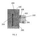
- FIG. 2is a rear view of the television 100 .
- the television 100includes a card bay 200 , in this case a recessed region at the rear of the television.
- the card bay 200includes a card bay electrical interface 202 , which may be in the form of a female socket.
- FIG. 2also illustrates the internet access card 102 , which includes a card housing 206 .
- the internet access card 102also includes card leads 208 , which may be in the form of a male socket with double sided leads (i.e., leads on each side of a printed circuit board).
- the card housing 206may include a card guide 210 .
- the card guide 210is a recessed region within the card housing 206 .
- the card guide 210is configured to engage a protruding card bay guide 204 in card bay 200 .
- this guide arrangementprovides a mechanical key that allows for engagement with the card bay electrical interface 202 only when the card 102 is properly positioned.
- the guide arrangementalso operates to support the card 102 when engaged with the card bay electrical interface 202 .
- FIG. 3illustrates electrical components associated with internet access card 102 .
- the cardincludes a set of card leads 208 , which may be placed on top and bottom surfaces of a printed circuit board 300 .
- Exemplary pin assignmentsare as follows:
- the different pinsmay be characterized as follows.
- FUTUREThis means that the line is reserved for future definition. The line is not connected in this embodiment of the card.
- GNDThese are the system ground pins. Preferably, they are the longest pin on the male card edge connector, such that they contact the female connector first.
- 5VIn one embodiment, there is 6 W of 5V power.
- the HDMI specificationrequires 4.8V to 5.3V. In one embodiment, these pins are the 2 nd longest pins.
- HPDThis is the standard HDMI Hot Plug Detect (HPD) pin as defined in the HDMI specification for a HDMI source (TV card).
- CECThis is the standard HDMI Consumer Electronics Control (CEC) line, as defined by the HDMI specification.
- CLK+, CLK ⁇This is the standard HDMI TMDS clock pair used to transmit data from the source (card 102 ) to the sink (TV 100 ).
- D0+,D0 ⁇This is the standard HDMI TMDS data pair 0 used to transmit data from the source (card 102 ) to the sink (TV 100 ).
- D1+,D1 ⁇This is the standard HDMI TMDS data pair 1 used to transmit data from the source (card 102 ) to the sink (TV 100 ).
- D2+,D2 ⁇This is the standard HDMI TMDS data pair 2 used to transmit data from the source (card 102 ) to the sink (TV 100 ).
- HDMI SDAThis is the HDMI standard Display Data Channel (DDC) I2C data line used to read the EDID from the sink (TV 100 ).
- DDCDisplay Data Channel
- HDMI SCLThis is the HDMI standard Display Data Channel (DDC) I2C clock line used to read the EDID from the sink (TV 100 ).
- DDCDisplay Data Channel
- Serial Data TXThis is the Transmit serial data line with data direction from the TV 100 to the card 102 .
- the voltage signaling level on this cardmay be 3.3V.
- the baud ratemay be 119200, and the protocol may be N,8,1.
- the signaling levelmay be specified by a Universal Asynchronous Receiver/Transmitter (UART) and may be inverted from the normal sense of 12V RS232.
- UARTUniversal Asynchronous Receiver/Transmitter
- Serial Data RXThis is the Receive serial data line with data direction from the card 102 to the TV 100 .
- the voltage signaling level on this cardmay be 3.3V.
- the baud ratemay be 119200, and the protocol may be N,8,1.
- the signaling levelis from the UART and is inverted from the normal sense of 12V RS232.
- Reset_nThis is the active low reset signal from the TV 100 to the card 102 .
- the TV 100should hold this line low as long as there is no card inserted. When a card 102 is inserted, the TV is to keep this line low for about 200 mS, then raise this line to 3.3V. If the TV is unplugged and plugged back in, then the TV should hold the line low for 200 mS and raise the line to 3.3V. This line will not be toggled when the user turns the TV on and off
- TV_WakeReq_nThe card 102 makes this signal go low to request the TV 100 to wake up. This signal is used to wake up the TV in the condition for example if the user presses a key on the RF remote 104 . Under normal conditions this signal is high.
- TV_StbyState_nThis signal is low when the TV is in standby mode. It is high when the TV is in regular running mode. The TV drives this signal.
- Crd_StbyState_nThe card 102 makes this signal go low when the card 102 is in standby mode; it will go high when the card 102 is in normal power mode.
- CARD_DETAnThe card 102 grounds this signal when the card is inserted. It may do this by connecting this pin to a ground pin on the card 102 .
- the TV 100pulls up this signal with a ⁇ 10K resistor, and then when this signal goes low it lets the TV know that a card has been inserted.
- FIG. 3illustrates the processor 302 receiving some of these signals.
- audio/video (A/V)corresponds to specified HDMI signals
- serialcorresponds to the UART serial signals
- clockcorresponds to the different specified clock signals.
- the processor 302may be an embedded multimedia applications processor, such as the BCM 2835, sold by Broadcom, Irvine, Calif.
- the printed circuit board 300also hosts a power management chip 312 , which may be the BCM959002 power management unit sold by Broadcom, Irvine, Calif.
- the power management chip 312receives a power signal from leads 208 .
- the card 102does not require a separate power supply.
- the serial link of FIG. 3may be any communication link configured to support a specified communication protocol.
- the specified communication protocolmay be Consumer Electronics Control (CEC), Serial Peripheral Interface Bus (SPI), Inter-Integrated Circuit (I2C) or a parallel bus.
- CECConsumer Electronics Control
- SPISerial Peripheral Interface Bus
- I2CInter-Integrated Circuit
- the processor 302is also connected to a WiFi circuit 304 , which may include one or more antennas.
- the WiFi circuitsupports wireless communications, with for example, a wireless router.
- An Ethernet port 308may also be provided, which allows for a hardwired connection to the internet.
- An interface module 310is also connected to the processor 302 .
- the interface moduleis a set of executable instructions stored in memory, which are executed by the processor 302 .
- the interface module 310provides a graphical user interface for display on the television 100 . That is, in certain modes, the card 102 operates as a master device, while the television 100 operates as a slave device. Control signals to the television 100 may be supplied with CEC commands in the HDMI protocol. For example, an infrared receiver on the television may receive a command from a remote. The television sends the command over the internal HDMI CEC link to the card 102 . The card 102 may then provide the appropriate command back to the television 100 via an HDMI CEC link.
- FIG. 4illustrates a television 100 configured in accordance with an embodiment of the invention.
- the television 100is configured to include the card bay electrical interface 202 .
- This interfaceis relatively inexpensive and therefore does not present a barrier to adoption for television manufacturers.
- Other inputsmay include a tuner 402 (e.g., a high definition television tuner) and an auxiliary interface 404 .
- An audio/visual signal source multiplexer 406operates under the control of the processor 408 to select an audio/visual signal input.
- the processor 408performs standard functions to produce a visual signal at display 410 and an audio signal at speaker 412 .
- the television 100also includes a standard power management circuit 414 . Observe that the card bay electrical interface 202 provides a link to the internal electronics of the television 100 . This allows the card 102 to control the television 100 , such as to provide a graphical user interface from the interface module 310 .
- the card 102is 3 inches wide, 4 inches long and 0.75 inches thick.
- the inventionis operative with a simple remote.
- buttonsmay include a home key, back key, OK key, left navigation key, right navigation key, up navigation key, down navigation key, play/pause key, double arrow left key, and a double arrow right key.
- Alphanumeric keysare not required.
- the interface module 310provides a graphical user interface that allows a user to navigate through content using only the specified keys.
- the home keymay be used to invoke control by the card 102 .
- control by the card 102may be invoked by using a remote to toggle through different video input selections.
- a separate remotemay be used with the card 102 .
- signals from a universal remote or dedicated remote for a television manufacturermay be mapped to operations, as specified by the interface module 310 .
- FIG. 5illustrates a media streaming device 510 configured in accordance with an embodiment of the invention.
- the device 510is configured to connect with the television 100 .
- the device 510is configured to stream media content from a source and make the streamed media accessible to the television 100 .
- the device 510can also be configured to control the functionality of the television 100 .
- a cable 502operates as an interface with television 100 .
- Television 100corresponds to television 100 of FIG. 4 , but instead of the card bay interface 202 of FIG. 4 , a cable interface 500 is used.
- the cable interface 500is a Mobile High-Definition Link (MHL) cable interface.
- the cable interface 500is directly connected with a connector 504 without the use of the cable 502 while still utilizing an MHL interface through a connector such as HDMI connector, universal serial bus (USB) connector, and micro USB connector.
- MHLis a proposed industry standard for a mobile audio/video interface for directly connecting mobile phones to high-definition televisions (HDTVs) and displays.
- the MHL standardfeatures a single cable or connector with a low pin-count interface able to support up to 1080p high-definition (HD) video and digital audio while simultaneously providing power for the connected device.
- the cable interface 500is configured to decode signals received from the cable 502 or through the connector 504 .
- the connector 504is configured to encode signals from the device 510 .
- the device 510is a dedicated device capable of streaming media to the television 100 and controlling the television 100 .
- the connector 504 on the device 510may be in any number of forms because MHL is connection agnostic.
- the interfacemay be a micro Universal Serial Bus (USB) connection or an HDTV connection (e.g., HDMI).
- the device 510also includes a processor 512 and interface module 514 .
- the interface module 514supports MHL standard operations along with other operations specified in connection with other embodiments of the disclosed technology.
- a power management circuit 516manages the power coming into the device 510 from the television 100 .
- the device 510is powered from a lead at connector 504 and via the television 100 .
- a WiFi circuit 518is also resident within the device 510 .
- An antenna 520is connected to the WiFi circuit 518 .
- the antenna 520may be formed on a printed circuit board (not shown) associated with the components of the device 510 . Alternately, the antenna 520 may be incorporated into cable 502 or another externally mounted device.
- the antenna 520is externally mounted outside the device 510 and is coupled to the device 510 via a connector.
- an externally mounted antennacan be located away from the device 510 and near the television 100 to optimize a signal being received by the antenna 520 for use by the device 510 .
- the antenna 520is comprised of a conductive medium such as a wire and is located external of the device 510 .
- the remote 104is configured to communicate with the device 510 .
- the interface module 514is configured to be responsive to the remote 104 . This allows the interface module 514 to operate as a master control device, with the television 100 operating as a slave device.
- the interface module 514may include an infrared sensor to communicate with the remote 104 .
- the remote 104controls both the device 510 and the television 100 .
- the remote 104is configured as a simplified remote. For example, to access streaming content, only a small set of buttons is required, which may include a home key, back key, OK key, left navigation key, right navigation key, up navigation key, down navigation key, play/pause key, double arrow left key, and a double arrow right key. Alphanumeric keys are not required. Instead, the interface module 514 provides a graphical user interface that allows a user to navigate through content using only the specified keys. The home key may be used to invoke control of the television 100 by the device 510 .
- the television 100may lack the ability to control volume selection, channel selection, and/or source selection.
- the television 100has the capability of volume control, channel selection, and source selection.
- the remote 104can serve as the primary interface and control both the device 510 and the television 100 .
- the remote 104is configured to control the source selection, channel selection and/or volume for the television 100 by sending the appropriate instructions through the interface module 514 of the device 510 .
- these instructionsare further encoded by the interface module 514 from instructions from the remote 104 into a format that can be used to control the television 100 .
- the functionality of the interface module 514is separated into two distinct modules; one module for interfacing with the remote 104 commands and another module for encoding instructions into another format such as the MHL interface.
- representations of these instructions originating from the remote 104are routed to the television 100 through the connector 504 .
- the connector 504utilizes the MHL interface to control the television 100 .
- the remote 104is configured to control streaming media and other functionality of the device 510 in addition to controlling aspects of the television 100 such as volume, channel selection and source selection.
- control by the device 510may be invoked by using a remote to toggle through different video input selections.
- a separate remotemay be used with the device 510 .
- signals from a universal remote or dedicated remote for a television manufacturermay be mapped to operations, as specified by the interface module 514 .
- An embodiment of the present inventionrelates to a computer storage product with a computer readable storage medium having computer code thereon for performing various computer-implemented operations.
- the media and computer codemay be those specially designed and constructed for the purposes of the present invention, or they may be of the kind well known and available to those having skill in the computer software arts.
- Examples of computer-readable mediainclude, but are not limited to: magnetic media such as hard disks, floppy disks, and magnetic tape; optical media such as CD-ROMs, DVDs and holographic devices; magneto-optical media; and hardware devices that are specially configured to store and execute program code, such as application-specific integrated circuits (“ASICs”), programmable logic devices (“PLDs”) and ROM and RAM devices.
- ASICsapplication-specific integrated circuits
- PLDsprogrammable logic devices
- Examples of computer codeinclude machine code, such as produced by a compiler, and files containing higher-level code that are executed by a computer using an interpreter.
- machine codesuch as produced by a compiler
- files containing higher-level codethat are executed by a computer using an interpreter.
- an embodiment of the inventionmay be implemented using JAVA®, C++, or other object-oriented programming language and development tools.
- Another embodiment of the inventionmay be implemented in hardwired circuitry in place of, or in combination with, machine-executable software instructions.
Landscapes
- Engineering & Computer Science (AREA)
- Multimedia (AREA)
- Signal Processing (AREA)
- Human Computer Interaction (AREA)
- Computer Networks & Wireless Communication (AREA)
- Two-Way Televisions, Distribution Of Moving Picture Or The Like (AREA)
Abstract
Description
| Pin | Side A | Side B | Comments |
| 1 | 5 V | GND | Ground pins are longest |
| 2 | GND | 5 V | 5 V at 6 W total |
| 3 | HPD | CEC | |
| 4 | GROUND | CLK+ | HDMI Out CLK + and − |
| 5 | GROUND | CLK− | |
| 6 | D0+ | GROUND | HDMI Out D0 + and − |
| 7 | D0− | GROUND | |
| 8 | GROUND | D1+ | HDMI Out D1 + and − |
| 9 | GROUND | D1− | |
| 10 | D2+ | GROUND | HDMI Out D2 + and − |
| 11 | D2− | GROUND |
| Mechanical KEY |
| 12 | HDMI SDA | Serial Data TX | TX from TV to Card, |
| 119200, N, 8, 1, 3.3 V | |||
| 13 | HDMI SCL | Serial Data RX | RX from Card to TV, |
| 119200, N, 8, 1, 3.3 V | |||
| 14 | Reset_n | FUTURE | Reset goes low to reset our |
| card, high to run | |||
| 15 | TV_WakeReq_n | TV_StbyState_n | Used to wake the TV up |
| from standby | |||
| 16 | Crd_StbyReq_n | Crd_StbyState_n | Standby goes low request |
| card standby | |||
| 17 | FUTURE | 5 V | |
| 18 | CARD_DETAn | GROUND | Ground pins are longest |
Claims (10)
Priority Applications (9)
| Application Number | Priority Date | Filing Date | Title |
|---|---|---|---|
| US13/340,507US9131260B2 (en) | 2011-10-31 | 2011-12-29 | Streaming media system |
| US13/347,619US9286854B2 (en) | 2011-10-31 | 2012-01-10 | Multi-interface streaming media system |
| US14/839,379US9544654B2 (en) | 2011-10-31 | 2015-08-28 | Streaming media system |
| US15/043,115US9848231B2 (en) | 2011-10-31 | 2016-02-12 | Multi-interface streaming media system |
| US15/812,698US10219030B2 (en) | 2011-10-31 | 2017-11-14 | Multi-interface streaming media system |
| US16/272,164US10750235B2 (en) | 2011-10-31 | 2019-02-11 | Multi-interface streaming media system |
| US16/987,004US11523173B2 (en) | 2011-10-31 | 2020-08-06 | Multi-interface streaming media system |
| US17/978,837US12149780B2 (en) | 2011-10-31 | 2022-11-01 | Multi-interface streaming media system |
| US18/903,261US20250021404A1 (en) | 2011-10-31 | 2024-10-01 | Multi-interface streaming media system |
Applications Claiming Priority (2)
| Application Number | Priority Date | Filing Date | Title |
|---|---|---|---|
| US13/286,122US20130111537A1 (en) | 2011-10-31 | 2011-10-31 | Internet Access Card For Deployment Within A Television |
| US13/340,507US9131260B2 (en) | 2011-10-31 | 2011-12-29 | Streaming media system |
Related Parent Applications (1)
| Application Number | Title | Priority Date | Filing Date |
|---|---|---|---|
| US13/286,122Continuation-In-PartUS20130111537A1 (en) | 2011-10-31 | 2011-10-31 | Internet Access Card For Deployment Within A Television |
Related Child Applications (2)
| Application Number | Title | Priority Date | Filing Date |
|---|---|---|---|
| US13/347,619Continuation-In-PartUS9286854B2 (en) | 2011-10-31 | 2012-01-10 | Multi-interface streaming media system |
| US14/839,379ContinuationUS9544654B2 (en) | 2011-10-31 | 2015-08-28 | Streaming media system |
Publications (2)
| Publication Number | Publication Date |
|---|---|
| US20130111521A1 US20130111521A1 (en) | 2013-05-02 |
| US9131260B2true US9131260B2 (en) | 2015-09-08 |
Family
ID=48173860
Family Applications (2)
| Application Number | Title | Priority Date | Filing Date |
|---|---|---|---|
| US13/340,507Active2032-01-26US9131260B2 (en) | 2011-10-31 | 2011-12-29 | Streaming media system |
| US14/839,379ActiveUS9544654B2 (en) | 2011-10-31 | 2015-08-28 | Streaming media system |
Family Applications After (1)
| Application Number | Title | Priority Date | Filing Date |
|---|---|---|---|
| US14/839,379ActiveUS9544654B2 (en) | 2011-10-31 | 2015-08-28 | Streaming media system |
Country Status (1)
| Country | Link |
|---|---|
| US (2) | US9131260B2 (en) |
Cited By (18)
| Publication number | Priority date | Publication date | Assignee | Title |
|---|---|---|---|---|
| US20140372558A1 (en)* | 2013-06-17 | 2014-12-18 | Thomson Licensing | Wifi display compatible network gateway |
| US9448606B2 (en)* | 2014-09-23 | 2016-09-20 | Broadcom Corporation | Adaptive power configuration for a MHL and HDMI combination multimedia device |
| USD775233S1 (en) | 2015-09-18 | 2016-12-27 | Google Inc. | Media streaming device |
| US9544654B2 (en) | 2011-10-31 | 2017-01-10 | Roku, Inc. | Streaming media system |
| USD776162S1 (en)* | 2015-09-18 | 2017-01-10 | Google Inc. | Media streaming device |
| USD781919S1 (en) | 2015-09-18 | 2017-03-21 | Google Inc. | Media streaming device |
| USD788820S1 (en) | 2015-09-18 | 2017-06-06 | Google Inc. | Media streaming device |
| USD797149S1 (en) | 2015-09-18 | 2017-09-12 | Google Inc. | Media streaming device |
| USD797807S1 (en) | 2016-03-17 | 2017-09-19 | Google Inc. | Media streaming device |
| US20170269664A1 (en)* | 2016-03-15 | 2017-09-21 | Roku, Inc. | Brown out condition detection and device calibration |
| USD802627S1 (en)* | 2016-10-04 | 2017-11-14 | Google Llc | Media streaming device |
| USD804531S1 (en) | 2015-09-18 | 2017-12-05 | Google Inc. | Media streaming device |
| USD804532S1 (en)* | 2016-10-04 | 2017-12-05 | Google Llc | Media streaming device |
| USD804533S1 (en)* | 2016-10-04 | 2017-12-05 | Google Llc | Media streaming device |
| US9848231B2 (en) | 2011-10-31 | 2017-12-19 | Roku, Inc. | Multi-interface streaming media system |
| US20190326951A1 (en)* | 2015-09-08 | 2019-10-24 | Google Llc | Audio media streaming device |
| US11342073B2 (en) | 2017-09-29 | 2022-05-24 | Fresenius Medical Care Holdings, Inc. | Transmitted display casting for medical devices |
| US11375271B2 (en) | 2015-09-08 | 2022-06-28 | Google Llc | Video media streaming device |
Families Citing this family (8)
| Publication number | Priority date | Publication date | Assignee | Title |
|---|---|---|---|---|
| US20130174042A1 (en)* | 2011-12-30 | 2013-07-04 | Samsung Electronics Co., Ltd. | Display apparatus, upgrading apparatus, display system and control method thereof |
| US9420329B2 (en) | 2014-10-21 | 2016-08-16 | Bby Solutions, Inc. | Multistream tuner stick device for receiving and streaming digital content |
| US9420214B2 (en)* | 2014-10-21 | 2016-08-16 | Bby Solutions, Inc. | Television tuner device for processing digital audiovisual content |
| US20180014075A1 (en)* | 2014-12-24 | 2018-01-11 | Magic Media Works Limited | Media playback device and system |
| US10084498B2 (en)* | 2015-09-16 | 2018-09-25 | Gm Global Technology Operations, Llc. | Configurable communications module with replaceable network access device |
| US11181943B2 (en)* | 2015-12-16 | 2021-11-23 | Lenovo (Singapore) Pte. Ltd. | Electronic device with self-aligning accessory |
| US11140353B2 (en) | 2018-05-22 | 2021-10-05 | Amazon Technologies, Inc. | Media device with on-board patch antenna with dual antenna feeds |
| US11134298B2 (en) | 2018-05-22 | 2021-09-28 | Amazon Technologies, Inc. | Media device with on-board patch antennas |
Citations (10)
| Publication number | Priority date | Publication date | Assignee | Title |
|---|---|---|---|---|
| US5675390A (en)* | 1995-07-17 | 1997-10-07 | Gateway 2000, Inc. | Home entertainment system combining complex processor capability with a high quality display |
| US6745223B1 (en)* | 2000-01-26 | 2004-06-01 | Viaclix, Inc. | User terminal for channel-based internet network |
| US6965593B2 (en) | 1996-11-12 | 2005-11-15 | Ds Systems, Inc. | High bandwidth broadcast system having localized multicast access to broadcast content |
| US20070250872A1 (en) | 2006-03-21 | 2007-10-25 | Robin Dua | Pod module and method thereof |
| US20080134237A1 (en) | 2006-08-18 | 2008-06-05 | Sony Corporation | Automatically reconfigurable multimedia system with interchangeable personality adapters |
| US20090313675A1 (en) | 2008-06-13 | 2009-12-17 | Embarq Holdings Company, Llc | System and Method for Distribution of a Television Signal |
| US7694326B2 (en)* | 2002-05-17 | 2010-04-06 | Sony Corporation | Signal processing system and method, signal processing apparatus and method, recording medium, and program |
| US20100261510A1 (en)* | 2009-04-14 | 2010-10-14 | Qualcomm Incorporated | System and method for triggering a wireless connection |
| US20110037447A1 (en) | 2009-08-17 | 2011-02-17 | Hugh Thomas Mair | Component Powered by HDMI Interface |
| US8208001B2 (en) | 2008-09-12 | 2012-06-26 | Embarq Holdings Company, Llc | System and method for encoding changes for video conferencing through a set-top box |
Family Cites Families (4)
| Publication number | Priority date | Publication date | Assignee | Title |
|---|---|---|---|---|
| NZ259147A (en) | 1992-12-09 | 1997-05-26 | Discovery Communicat Inc | Network controller for cable television |
| US20130111537A1 (en) | 2011-10-31 | 2013-05-02 | Roku, Inc. | Internet Access Card For Deployment Within A Television |
| US9131260B2 (en) | 2011-10-31 | 2015-09-08 | Roku, Inc. | Streaming media system |
| US9286854B2 (en) | 2011-10-31 | 2016-03-15 | Roku, Inc. | Multi-interface streaming media system |
- 2011
- 2011-12-29USUS13/340,507patent/US9131260B2/enactiveActive
- 2015
- 2015-08-28USUS14/839,379patent/US9544654B2/enactiveActive
Patent Citations (10)
| Publication number | Priority date | Publication date | Assignee | Title |
|---|---|---|---|---|
| US5675390A (en)* | 1995-07-17 | 1997-10-07 | Gateway 2000, Inc. | Home entertainment system combining complex processor capability with a high quality display |
| US6965593B2 (en) | 1996-11-12 | 2005-11-15 | Ds Systems, Inc. | High bandwidth broadcast system having localized multicast access to broadcast content |
| US6745223B1 (en)* | 2000-01-26 | 2004-06-01 | Viaclix, Inc. | User terminal for channel-based internet network |
| US7694326B2 (en)* | 2002-05-17 | 2010-04-06 | Sony Corporation | Signal processing system and method, signal processing apparatus and method, recording medium, and program |
| US20070250872A1 (en) | 2006-03-21 | 2007-10-25 | Robin Dua | Pod module and method thereof |
| US20080134237A1 (en) | 2006-08-18 | 2008-06-05 | Sony Corporation | Automatically reconfigurable multimedia system with interchangeable personality adapters |
| US20090313675A1 (en) | 2008-06-13 | 2009-12-17 | Embarq Holdings Company, Llc | System and Method for Distribution of a Television Signal |
| US8208001B2 (en) | 2008-09-12 | 2012-06-26 | Embarq Holdings Company, Llc | System and method for encoding changes for video conferencing through a set-top box |
| US20100261510A1 (en)* | 2009-04-14 | 2010-10-14 | Qualcomm Incorporated | System and method for triggering a wireless connection |
| US20110037447A1 (en) | 2009-08-17 | 2011-02-17 | Hugh Thomas Mair | Component Powered by HDMI Interface |
Non-Patent Citations (1)
| Title |
|---|
| Office Action issued to U.S. Appl. No. 13/286,122, Jan. 31, 2013, 16 pgs. |
Cited By (30)
| Publication number | Priority date | Publication date | Assignee | Title |
|---|---|---|---|---|
| US10750235B2 (en) | 2011-10-31 | 2020-08-18 | Roku, Inc. | Multi-interface streaming media system |
| US9544654B2 (en) | 2011-10-31 | 2017-01-10 | Roku, Inc. | Streaming media system |
| US9848231B2 (en) | 2011-10-31 | 2017-12-19 | Roku, Inc. | Multi-interface streaming media system |
| US12149780B2 (en) | 2011-10-31 | 2024-11-19 | Roku, Inc. | Multi-interface streaming media system |
| US11523173B2 (en) | 2011-10-31 | 2022-12-06 | Roku, Inc. | Multi-interface streaming media system |
| US10187925B2 (en)* | 2013-06-17 | 2019-01-22 | Interdigital Ce Patent Holdings | WiFi display compatible network gateway |
| US20140372558A1 (en)* | 2013-06-17 | 2014-12-18 | Thomson Licensing | Wifi display compatible network gateway |
| US9448606B2 (en)* | 2014-09-23 | 2016-09-20 | Broadcom Corporation | Adaptive power configuration for a MHL and HDMI combination multimedia device |
| US11277169B2 (en)* | 2015-09-08 | 2022-03-15 | Google Llc | Audio media streaming device |
| US20190326951A1 (en)* | 2015-09-08 | 2019-10-24 | Google Llc | Audio media streaming device |
| US11943500B2 (en) | 2015-09-08 | 2024-03-26 | Google Llc | Video media streaming device |
| US11375271B2 (en) | 2015-09-08 | 2022-06-28 | Google Llc | Video media streaming device |
| USD776162S1 (en)* | 2015-09-18 | 2017-01-10 | Google Inc. | Media streaming device |
| USD804531S1 (en) | 2015-09-18 | 2017-12-05 | Google Inc. | Media streaming device |
| USD797149S1 (en) | 2015-09-18 | 2017-09-12 | Google Inc. | Media streaming device |
| USD788820S1 (en) | 2015-09-18 | 2017-06-06 | Google Inc. | Media streaming device |
| USD781919S1 (en) | 2015-09-18 | 2017-03-21 | Google Inc. | Media streaming device |
| USD775233S1 (en) | 2015-09-18 | 2016-12-27 | Google Inc. | Media streaming device |
| US11023027B2 (en)* | 2016-03-15 | 2021-06-01 | Roku, Inc. | Brown out condition detection and device calibration |
| US10437304B2 (en)* | 2016-03-15 | 2019-10-08 | Roku, Inc. | Brown out condition detection and device calibration |
| US20190302864A1 (en)* | 2016-03-15 | 2019-10-03 | Roku, Inc. | Brown out condition detection and device calibration |
| WO2017160731A1 (en)* | 2016-03-15 | 2017-09-21 | Roku, Inc. | Brown out condition detection and device calibration |
| US20170269664A1 (en)* | 2016-03-15 | 2017-09-21 | Roku, Inc. | Brown out condition detection and device calibration |
| US11983057B2 (en) | 2016-03-15 | 2024-05-14 | Roku, Inc. | Brown out condition detection and device calibration |
| US12292774B2 (en) | 2016-03-15 | 2025-05-06 | Roku, Inc. | Brown out condition detection and device calibration |
| USD797807S1 (en) | 2016-03-17 | 2017-09-19 | Google Inc. | Media streaming device |
| USD804533S1 (en)* | 2016-10-04 | 2017-12-05 | Google Llc | Media streaming device |
| USD804532S1 (en)* | 2016-10-04 | 2017-12-05 | Google Llc | Media streaming device |
| USD802627S1 (en)* | 2016-10-04 | 2017-11-14 | Google Llc | Media streaming device |
| US11342073B2 (en) | 2017-09-29 | 2022-05-24 | Fresenius Medical Care Holdings, Inc. | Transmitted display casting for medical devices |
Also Published As
| Publication number | Publication date |
|---|---|
| US20150373417A1 (en) | 2015-12-24 |
| US9544654B2 (en) | 2017-01-10 |
| US20130111521A1 (en) | 2013-05-02 |
Similar Documents
| Publication | Publication Date | Title |
|---|---|---|
| US9544654B2 (en) | Streaming media system | |
| US12149780B2 (en) | Multi-interface streaming media system | |
| US9280506B1 (en) | Transfer of uncompressed multimedia contents or data communications | |
| US8799537B1 (en) | Transfer of uncompressed multimedia contents and data communications | |
| US8151018B2 (en) | Dual-mode data transfer of uncompressed multimedia contents or data communications | |
| CN103259999B (en) | HPD signal output control method, HDMI receiving device and system | |
| TWI505700B (en) | Pluggable electronic device and method for determining output data of pluggable electronic device | |
| US20160011999A1 (en) | Apparatus for inter-connection and multi-screen interactive communication, system and method employing the same | |
| US20090307734A1 (en) | Communication device for providing communication between electronic apparatuses | |
| US20110321115A1 (en) | Tv function expansion component using gold finger connector | |
| US10339090B2 (en) | System for implementing MXM on a PCI card | |
| US20110321116A1 (en) | Tv signal switching box and controlling method thereof | |
| WO2010075686A1 (en) | Television capable of implementing function extension | |
| US20130111537A1 (en) | Internet Access Card For Deployment Within A Television | |
| TW201606513A (en) | Display system and display device and TV stick | |
| CN108205512B (en) | High-resolution multimedia interface device and control method thereof | |
| CN105264882B (en) | Function extension of display device and control method thereof | |
| US20100169517A1 (en) | Multimedia Switch Circuit and Method | |
| CN118250505A (en) | Electronic device and corresponding method for delivering EDID extensions identifying connected input sources | |
| CN113885826A (en) | All-in-one device and speaker expansion method, device and system | |
| CN104810005B (en) | Pluggable electronic device and method for determining output data of pluggable electronic device | |
| TWI709076B (en) | Motherboard outputting image data and operation system | |
| WO2016103916A1 (en) | Communication system and communication method | |
| KR20230067993A (en) | Hdmi bidirectional control circuit and electronic device having the same |
Legal Events
| Date | Code | Title | Description |
|---|---|---|---|
| AS | Assignment | Owner name:ROKU, INC., CALIFORNIA Free format text:ASSIGNMENT OF ASSIGNORS INTEREST;ASSIGNORS:KLARKE, LLOYD;GARNER, GREG;SASSENRATH, CARL;AND OTHERS;SIGNING DATES FROM 20120306 TO 20120313;REEL/FRAME:027858/0366 | |
| AS | Assignment | Owner name:SILICON VALLEY BANK, CALIFORNIA Free format text:SECURITY AGREEMENT;ASSIGNOR:ROKU, INC.;REEL/FRAME:028316/0958 Effective date:20120531 | |
| STCF | Information on status: patent grant | Free format text:PATENTED CASE | |
| AS | Assignment | Owner name:SILICON VALLEY BANK, CALIFORNIA Free format text:AMENDED AND RESTATED INTELLECTUAL PROPERTY SECURITY AGREEMENT;ASSIGNOR:ROKU, INC.;REEL/FRAME:042768/0268 Effective date:20170609 | |
| FEPP | Fee payment procedure | Free format text:ENTITY STATUS SET TO UNDISCOUNTED (ORIGINAL EVENT CODE: BIG.); ENTITY STATUS OF PATENT OWNER: LARGE ENTITY | |
| MAFP | Maintenance fee payment | Free format text:PAYMENT OF MAINTENANCE FEE, 4TH YEAR, LARGE ENTITY (ORIGINAL EVENT CODE: M1551); ENTITY STATUS OF PATENT OWNER: LARGE ENTITY Year of fee payment:4 | |
| AS | Assignment | Owner name:MORGAN STANLEY SENIOR FUNDING, INC., MARYLAND Free format text:PATENT SECURITY AGREEMENT;ASSIGNOR:ROKU, INC.;REEL/FRAME:048385/0375 Effective date:20190219 | |
| AS | Assignment | Owner name:ROKU, INC., CALIFORNIA Free format text:RELEASE BY SECURED PARTY;ASSIGNOR:SILICON VALLEY BANK, AS BANK;REEL/FRAME:048420/0841 Effective date:20190222 Owner name:ROKU, INC., CALIFORNIA Free format text:RELEASE BY SECURED PARTY;ASSIGNOR:SILICON VALLEY BANK, AS BANK;REEL/FRAME:048420/0802 Effective date:20190222 | |
| AS | Assignment | Owner name:ROKU, INC., CALIFORNIA Free format text:TERMINATION AND RELEASE OF INTELLECTUAL PROPERTY SECURITY AGREEMENT (REEL/FRAME 048385/0375);ASSIGNOR:MORGAN STANLEY SENIOR FUNDING, INC.;REEL/FRAME:062826/0001 Effective date:20230221 | |
| MAFP | Maintenance fee payment | Free format text:PAYMENT OF MAINTENANCE FEE, 8TH YEAR, LARGE ENTITY (ORIGINAL EVENT CODE: M1552); ENTITY STATUS OF PATENT OWNER: LARGE ENTITY Year of fee payment:8 | |
| AS | Assignment | Owner name:CITIBANK, N.A., TEXAS Free format text:SECURITY INTEREST;ASSIGNOR:ROKU, INC.;REEL/FRAME:068982/0377 Effective date:20240916 |