US9130641B2 - Short-range cellular booster - Google Patents
Short-range cellular boosterDownload PDFInfo
- Publication number
- US9130641B2 US9130641B2US11/369,231US36923106AUS9130641B2US 9130641 B2US9130641 B2US 9130641B2US 36923106 AUS36923106 AUS 36923106AUS 9130641 B2US9130641 B2US 9130641B2
- Authority
- US
- United States
- Prior art keywords
- unit
- link
- user
- signal
- network
- Prior art date
- Legal status (The legal status is an assumption and is not a legal conclusion. Google has not performed a legal analysis and makes no representation as to the accuracy of the status listed.)
- Active, expires
Links
Images


Classifications
- H—ELECTRICITY
- H04—ELECTRIC COMMUNICATION TECHNIQUE
- H04B—TRANSMISSION
- H04B7/00—Radio transmission systems, i.e. using radiation field
- H04B7/14—Relay systems
- H04B7/15—Active relay systems
- H04B7/155—Ground-based stations
- H—ELECTRICITY
- H04—ELECTRIC COMMUNICATION TECHNIQUE
- H04B—TRANSMISSION
- H04B7/00—Radio transmission systems, i.e. using radiation field
- H04B7/14—Relay systems
- H04B7/15—Active relay systems
- H04B7/155—Ground-based stations
- H04B7/15528—Control of operation parameters of a relay station to exploit the physical medium
- H04B7/15542—Selecting at relay station its transmit and receive resources
- H—ELECTRICITY
- H04—ELECTRIC COMMUNICATION TECHNIQUE
- H04B—TRANSMISSION
- H04B17/00—Monitoring; Testing
- H04B17/40—Monitoring; Testing of relay systems
- H—ELECTRICITY
- H04—ELECTRIC COMMUNICATION TECHNIQUE
- H04B—TRANSMISSION
- H04B7/00—Radio transmission systems, i.e. using radiation field
- H04B7/14—Relay systems
- H04B7/15—Active relay systems
- H04B7/155—Ground-based stations
- H04B7/15528—Control of operation parameters of a relay station to exploit the physical medium
- H04B7/15535—Control of relay amplifier gain
- H—ELECTRICITY
- H04—ELECTRIC COMMUNICATION TECHNIQUE
- H04B—TRANSMISSION
- H04B7/00—Radio transmission systems, i.e. using radiation field
- H04B7/24—Radio transmission systems, i.e. using radiation field for communication between two or more posts
- H04B7/26—Radio transmission systems, i.e. using radiation field for communication between two or more posts at least one of which is mobile
- H04B7/2603—Arrangements for wireless physical layer control
- H04B7/2606—Arrangements for base station coverage control, e.g. by using relays in tunnels
- H—ELECTRICITY
- H04—ELECTRIC COMMUNICATION TECHNIQUE
- H04B—TRANSMISSION
- H04B7/00—Radio transmission systems, i.e. using radiation field
- H04B7/14—Relay systems
- H04B7/15—Active relay systems
- H04B7/155—Ground-based stations
- H04B7/15564—Relay station antennae loop interference reduction
- H—ELECTRICITY
- H04—ELECTRIC COMMUNICATION TECHNIQUE
- H04B—TRANSMISSION
- H04B7/00—Radio transmission systems, i.e. using radiation field
- H04B7/14—Relay systems
- H04B7/15—Active relay systems
- H04B7/155—Ground-based stations
- H04B7/15564—Relay station antennae loop interference reduction
- H04B7/15585—Relay station antennae loop interference reduction by interference cancellation
Definitions
- the existing cellular networkssuch as (Global System for Mobile Communications (GSM) and IS95, are intended to provide a contagious and continuous coverage, so as to support the high terminal mobility expected from such systems.
- GSMGlobal System for Mobile Communications
- IS95IS95
- indoor (in-building) coverage, or the coverage of places with high shadowing attenuation (e.g. tunnels) of such networksis often “patchy”, with “coverage Holes” at best, and no coverage at worst.
- the reason for the impaired indoor coverageis that the cellular base stations are usually placed outside buildings, higher than the average building heights, to provide large area coverage.
- the signalmay be adequate at “street-level”, it is severely attenuated by the building material, reducing the signal power in-building, resulting in the poor converges.
- Loss of signal powerdepends on the building material and can be tens of dBs for each wall penetration. The problem is exacerbated in the 3 rd generation systems such as Wideband Code Division Multiple Access (WCDMA) and cdma2000, as these new systems have the capability of high data transmission, which results in lower information bit energy (E b ), and much reduced link budget and cell foot-print.
- WCDMAWideband Code Division Multiple Access
- cdma20003 rd generation systems
- E binformation bit energy
- the repeater solutionalthough cheaper than a base station, has several drawbacks. These outdoor repeaters are still too expensive for a private user, and involve careful planning. Most use large directional antennas, or additional backhaul frequencies to reduce antenna gain specifications, which results in lower spectral efficiency and are capacity limited.
- the repeatersoften cause increased interference in the network, as they are outdoor devices, similar to base stations, and hence are not popular as a viable solution for providing high performance indoor coverage.
- the indoor repeatersare still cheaper than the outdoor version, but typically involve installation of high directional antennas on the roof, and ensured antenna isolation, creating costly demand for skilled installation and operation. Therefore, the system generally remains too complicated for an unskilled user and not sufficiently inexpensive for usage in a very localized coverage area.
- a repeatermediates traffic between a network transceiver and a user transceiver in a wireless communication system.
- the repeatercomprises a network unit that maintains a network link with the network transceiver, a user unit that maintains a user link with the user transceiver, a two-way communication pathway between the network unit and the user unit; that facilitate the communication of signals between the network transceiver and the user transceiver in autonomous repeater hops between the network transceiver and the network unit, between the user transceiver and the user unit, and between the network unit and the user unit, and a gain controller that compensates for propagation losses between the network unit and user unit alone.
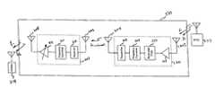
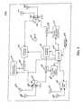
- FIG. 1is a schematic block diagram illustrating an embodiment of a cellular network with two base stations
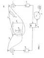
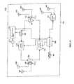
- FIG. 2is a schematic block diagram depicting an embodiment of a forward-link part of a repeater
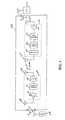
- FIG. 4is a schematic block diagram illustrating an embodiment of a system including a Network unit and a User unit;
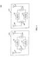
- FIG. 5is a schematic block diagram that illustrates an embodiment of a system including a Network unit implementing antenna diversity
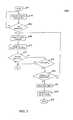
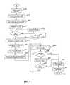
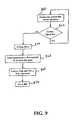
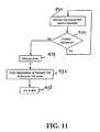
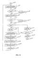
- FIGS. 7-11are flow charts depicting embodiments of system operation flow for a network unit ( 7 - 9 ) and a user unit ( 10 - 11 );
- FIGS. 12 and 13are schematic block diagrams showing embodiments of digital repeater implementations
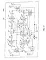
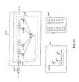
- FIG. 14is a schematic block diagram showing an embodiment of an analog implementation of a back-to-back repeater
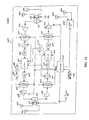
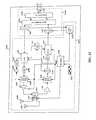
- FIG. 15is a schematic block diagram showing an embodiment of a digital implementation of a back-to-back repeater
- FIG. 16is a flow chart showing an embodiment of operation flow of a back-to-back repeater
- FIGS. 19-22are schematic block diagrams showing other repeater embodiments.
- the system disclosed hereinprovides better, and localized indoor coverage without causing excess interference in the network, usage of costly equipment or network planning.
- the systemincreases the overall network capacity, reducing the mobile and BTS transmit power, increasing the battery life and reducing the “harmful” radiation to the user.
- GSMGlobal System for Communications
- WCDMAWideband Code Division Multiple Access
- 802.11a, b, and gwireless LAN systems
- the operating frequencycan be at any desired part of communications spectrum used for mobile communications (e.g.
- PCS 1900, or DCS1800 or GSM900 or UMTS 2000, ISM or UNII bandThe description here is only intended as an example and as such utilization of the booster is not only limited to the in-building coverage and can be used in other places such as trains, planes, cars, tunnels, etc. Also, the example may not include all minute or unimportant design details. Units and sub-units discussed and explained hereafter meet regulations of the respective licensed and unlicensed band of operation. Therefore, for the different example implementations and embodiments disclosed, specifications including maximum transmit power, spectral mask, out of band radiation, and others for transmitters, receivers, repeaters and boosters, are met for both licensed and unlicensed bands of operation.
- BTS 1 101has an associated coverage area 103 .
- BTS 2 102has an associated coverage area 104 .
- These coverage areasmay or may not overlap. However, usually the network is planned such that there is considerable overlap, to facilitate handoffs.
- the mobile terminal 105is inside building 106 , in the coverage area 103 communicating with BTS 1 101 , using a traffic channel transmitted at around frequency f 1 in the forward-link and its associated reverse-link frequency, f 1 ′.
- the traffic channelcan be one of the available time slots on the BCCH carrier, or may be on a TCH carrier, where frequency hopping may be used to reduce interference.
- Mobile terminal 105may or may not be in coverage area 104 , but the mobile unit 105 is well within the coverage area 103 and average signal power from BTS 1 101 is much stronger than the average signal power from BTS 2 102 , within the building 106 , and the locality of mobile unit 105 .
- Root-mean-square (rms) forward-link signal level ⁇ 1outside the building 106 is higher than the rms signal level ⁇ 2 inside the building by the wall penetration loss ⁇ .
- the loss ⁇may be such that ⁇ 2 is not at sufficiently high level for the User unit 105 to maintain reliable communication with BTS 1 101 , or BTS 2 102 , or both BTS 1 101 and BTS 2 102 .
- the signal level ⁇ 2may be such that mobile unit 105 may have difficulty to setup and maintain a communication link with BTS 1 101 or BTS 2 102 , or both BTS 1 101 and BTS 2 102 , or the communication link does not have the desired performance and reliability, in all or some of the in-building areas.
- the coverage problem inside the building 106may be solved by more transmit power from BTS 1 101 in the down-link to combat the signal loss, by the wall penetration loss, a.
- the r.m.s. reverse-link signal level ⁇ 1inside the building 106 is higher than the r.m.s. signal level ⁇ ′ 2 , outside the building, by the wall penetration loss ⁇ ′.
- FIG. 2depicts a forward-link part 230 of the repeater 200 .
- the forward-link portion 230in a simple form supplies improved indoor coverage by boosting the signal level in building in the forward-link of the cellular network.
- BTS 1 213has a BCCH radio channel (beacon channel) transmitted substantially close to f 1 .
- BTS 1 213is in communications with the mobile unit 214 at a frequency substantially close to f 1 (the BCCH carrier frequency) or another carrier frequency, f 2 , that may or may not be frequency hopping. There may or may not be other frequencies that are transmitted by BTS 1 213 , or other base stations in the same area, which are not shown in the FIG. 2 .
- the devicehas two separate units, the “Forward-link Network unit” 201 , which is placed where good signal coverage exists, indoor or outdoors, and the “Forward-link User unit” 202 , which is placed where good signal coverage does not exist, indoor or outdoors.
- the Forward-link Network unit 201is connected to an antenna 203 , tuned to operate at the cellular network operating frequency band.
- the Forward-link Network unit 201is also connected to an antenna 204 tuned to operate at a suitable Unlicensed National Information Infrastructure (known as U-NII) bands, where the system is designed to operate at U-NII spectrum bands.
- U-NIIUnlicensed National Information Infrastructure
- the systemcan also be designed to operate at Unlicensed Personal Communications Services (U-PCS) band or at Industrial, Scientific and Medical (ISM) band of frequencies.
- U-NIIUnlicensed National Information Infrastructure
- the choice of the unlicensed frequencydepends on the design of the equipment and the system specification. Frequencies defined in the portion of the radio spectrum known as U-NII bands may be implemented in some embodiments. Some design modifications are useful, for ISM band operation. The modifications are related to the minimum spreading factor of 10 specified for the ISM band operation, and the maximum allowed transmit power. If the system is designed to operate in ISM band, the signal may use further spread spectrum modulation/demodulation and other modifications to meet FCC 47 CFR Part-15, subpart E specifications.
- the “Forward-link User Unit” 202is connected to an antenna 205 tuned to operate in the same frequency band as antenna 204 , which is U-NII band in some embodiments.
- the Forward-link User unit 202is also connected to an antenna 206 tuned to operate at the cellular network operating band.
- Antenna 203is connected to a (Low Noise Amplifier) LNA unit 207 , which is further connected to a bandpass filter 232 .
- LNA unit 207may be a high performance amplifier, with a typical gain of 15 dB and a noise figure of 1.5 dB with sufficient bandwidth to cover the appropriate portion of the spectrum.
- the bandpass filter 232can be designed to pass all or a desired part of the interested cellular spectrum, or can be a bank of overlapping bandpass filters, covering the full spectrum of the interested cellular system, with a RF switch, such that the desired band and bandwidth can be selected.
- the bandpass filter 232is connected to frequency converter 208 .
- the frequency converter 208is capable of converting the cellular network operating spectrum band to a desirable part of the U-NII spectrum, and includes components such as mixers and filters for correct operation.
- the frequency converter 208is connected to the Forward-link Network unit transmitter 209 .
- the transmitter unit 209is designed to operate in U-NII band and conforms to the FCC 47 CFR Part-15, subpart E regulations, and can be as simple as a single amplifier operating at the desirable U-NII operation band, or more complex transmitter with amplifiers and filters, or even a WLAN transmitter such as 802.11a.
- the transmitter unit 209is connected to antenna 204 .
- Antenna 205is connected to the Forward-link User unit receiver 210 , which is designed to receive the signal transmitted by unit 201 .
- the receiver 210which is connected to frequency converter 211 , can be as simple as a single LNA operating at desirable U-NII band of device operation, or it can be better designed with additional functionalities such as variable attenuator and variable channel select filters, or even a WLAN receiver such as 802.11a (where the transmitter part of 802.11a is used in the Network unit 209 ).
- Frequency converter unit 211which is connected to receiver unit 210 and variable gain amplifier unit 212 , converts the input signals, from U-NII band, to the cellular network operating frequencies, and includes all components such as mixers and filters for correct operation.
- the frequency converter unit 211performs the opposite conversion operation of the frequency converter unit 208 , and includes all components such as mixers and filters for correct operation.
- the frequency converter 211is connected to the Variable Gain (VG) amplifier 212 , operating at the cellular network operating frequency band.
- the variable gain amplifier 212is connected to antenna 208 .
- Antenna 208will be transmitting signals with substantially similar frequencies to the frequencies transmitted by base station 213 , and meets cellular system specifications.
- the signal radiated by antenna 208which is an amplified repeated version of the original incident signal received by antenna unit 203 , will experience some loss in the power level, before returning and re-entering the antenna 203 again.
- the re-entered signal into antenna 203is termed “Down-link Returned-Signal” hereafter.
- the Down-link Returned-Signal path lossis the Down-link Returned-Signal path loss, and is termed here as the “Down-link System Path Loss” and referred to as PL d1 .
- the “Down-link System Link Gain”, which is here referred to as G d1 ,is defined as “the ratio of the r.m.s. signal value at the input to the antenna 208 terminator, to the r.m.s. signal value, at the antenna 203 terminator, where the Down-link System Path Loss, PL d1 , as defined above, is infinite (i.e. no EM coupling path between antenna 208 and antenna 203 ), and all the system and propagation path delays (from antenna 203 , through the system to antenna 208 ) are removed”.
- dg d1all values of PL d1 , G d1 , and dg d1 are all in dB.
- the value of dg d1ranges from 0 to PL d1 , and can be assumed to be 3 dB for the purposes of the description here. However, it is possible to select better values for dg d1 , where the system performance is optimized further.
- FIG. 3depicts an embodiment of the reverse-link part 330 of a repeater 300 .
- the reverse-link portion 330in a simple form improves indoor coverage by boosting signal level in building in the reverse-link of the cellular network to such level that attains acceptable link performance.
- BTS 1 302has a BCCH radio channel (beacon channel) transmitted substantially close to f 1 , and a frequency pair, f′ 1 on the reverse-link.
- BTS 1 302is in communications with the mobile unit 324 at a frequency substantially close to f′ 1 (the BCCH carrier frequency) or another carrier frequency, f′ 2 , that may or may not be frequency hopping. There may or may not be other frequencies that are transmitted by BTS 1 302 , or other base stations in the same area, which are not shown in the FIG. 3 .
- the devicehas two separate units, the “Reverse-link Network unit” 326 , which is placed where good signal coverage exists, indoor or outdoors, and the “Reverse-link User unit” 328 , which is placed where good signal coverage does not exist, indoor or outdoors.
- the Reverse-link Network unit 326is connected to an antenna 304 , tuned to operate at the cellular network operating frequency band.
- the Reverse-link Network unit 326is also connected to an antenna 312 tuned to operate at a suitable Unlicensed National Information Infrastructure (U-NII) bands, where the system is designed to operate at U-NII bands.
- U-NIIUnlicensed National Information Infrastructure
- the systemcan also be designed to operate at Unlicensed Personal Communications Services (U-PCS) band or at Industrial, Scientific and Medical (ISM) band of frequencies.
- the “Reverse-link User Unit” 328is connected to an antenna 314 tuned to operate in the same frequency band as antenna 312 , which is U-NII band for example.
- the Reverse-link User unit 328is also connected to an antenna 322 tuned to operate at cellular network operating band.
- Antenna 322is connected to a LNA unit 320 , which is further connected to a bandpass filter 321 .
- LNA unit 320may be a high performance amplifier with a typical gain of 15 dB and a noise figure of 1.5 dB with sufficient bandwidth to cover the appropriate portion of the spectrum.
- the bandpass filter 321can be designed to pass all or a desired part of the cellular spectrum, or can be a bank of overlapping bandpass filters, covering the full spectrum of the interested cellular system, with a RF switch, such that the desired band and bandwidth can be selected.
- the bandpass filter 321is connected to frequency converter 318 .
- the frequency converter 318is capable of converting the cellular network operating spectrum band to a desirable part of the U-NII spectrum, and includes all components such as mixers and filters for correct operation.
- the frequency converter 318is connected to the Reverse-link User unit transmitter 316 .
- the transmitter unit 316is designed to operate in U-NII band and conforms to the FCC 47 CFR Part-15, subpart E regulations, and can be as simple as a single amplifier operating at the desirable U-NII operation band, or a more complex transmitter with amplifiers and filters or even a WLAN transmitter such 802.11a.
- the transmitter unit 316is connected to antenna 314 .
- the frequency converter unit 308performs the opposite conversion operation of the frequency converter unit 318 .
- the frequency converter 308is connected to the variable gain amplifier 306 , operating at the cellular network operating frequency band.
- the variable gain amplifier 306is connected to antenna 304 .
- Antenna 304will be transmitting signals with substantially similar frequencies to the frequencies transmitted by mobile unit 324 .
- the signal radiated by antenna 304which is an amplified repeated version of the original incident signal received by antenna unit 322 , will experience some loss in the power level, before returning and re-entering the antenna 322 again.
- the re-entered signal into antenna 322is termed “Up-link Returned-Signal” hereafter.
- the variable gain amplifier unit 306 gainis set such that Up-link System Link Gain, G u1 , is less than the Up-link System Path Loss, PL u1 , by dg u1 , so as to avoid a “positive feed-back” loop in the system, i.e. G u1 ⁇ PL u1 ⁇ dg u1 ( dB )
- dg u1all values of PL u1 , G u1 , and dg u1 are in dB.
- the value of dg u1ranges from 0 to PL u1 , and can be assumed to be 3 dB for the purposes of the description here. However, it is possible to select better values for dg u1 , where the system performance is optimized further.
- G u1 levelis substantially similar to G d1 level
- PL u1 levelis substantially similar to PL d1 level
- dg u1 levelis substantially similar to dg d1 level.
- the duplex filter unit 528is designed for optimum performance, and meets specifications for cellular operation. Also, the transmit/receive antenna 204 in FIG. 2 and transmit/receive antenna 312 in FIG. 3 are replaced by a single antenna 508 and duplex filter 526 . Further, the transmit/receive antenna 205 in FIG. 2 and transmit/receive antenna 314 in FIG. 3 are replaced by a single antenna 510 and duplex filter 524 in FIG. 4 . Equally, the transmit/receive antenna 208 in FIG. 2 and transmit/receive antenna 322 in FIG. 3 are replaced by a single antenna 512 and duplex filter 522 in FIG. 4 . The duplex filter unit 522 is designed for optimum performance, and complies with specifications for cellular operation.
- the described booster systemtypically operates satisfactorily in limited scenarios. To ensure the correct operation of the booster system in all propagation and operating conditions, several features may be included in the system design.
- FIG. 5shows a system 600 including the Network unit 602 ( 502 in FIG. 4 ) with the new design features included.
- Two antennas 610 and 608are used for antenna diversity, instead of a single antenna 506 in FIG. 4 .
- two antennas 636 and 638are used for antenna diversity, instead of a single antenna 512 in FIG. 4 .
- any diversity-combining schemesuch as Maximal Ratio Combining, etc. can be used for the receiver chain, and transmit diversity schemes such as random phase change in one or both antennas for the transmitter chain
- a simple scheme that is based on antenna switched diversity with “continuous switching” strategyis suggested here.
- the continuous switching strategywith the switching rate selected for optimum performance (e.g.
- the RF switch 612 connected to antennas 610 and 608 and the duplex filter 614will provide switching operations for the cellular transmit/receive operation of the Network unit 602 .
- the RF switch 634connected to antennas 636 and 638 and the duplex filter 634 , will provide switching operations for the U-NII band transmit/receive operation of the Network unit 602 .
- a calibration signal generator/transmitter unit 622is coupled to the reverse-link transmitter path of the Network unit 602 , via the directional coupler 618 .
- the unit 622will provide a calibration signal, at the desired power levels, which is used to establish the level of the above-mentioned Up-link System Path Loss, PL u1 , which exists between the Network unit 602 ( 502 in FIG. 4 ) and the User unit 702 in FIG. 6 ( 504 in FIG. 4 ).
- the calibration signal generated by unit 622is transmitted via the diversity antennas 610 and 608 at a set transmit level which is substantially below any expected signal level from cellular network (e.g. 20 dB below the minimum expected cellular signal level).
- the calibration signal generated by unit 622is a direct-sequence spread spectrum signal modulated by a known Pseudo Random (PN) code with a known code phase (referred to hereafter as “own code” phase) and with a chipping rate comparable to the forward and reverse links of the Network unit 602 and User unit 702 (in FIG. 6 ) operating bandwidths.
- the code phasesare selected such that the minimum code phase difference is larger than the maximum expected path delay (measured in multiple number of chips), and after that the code phases should be multiple integer of the minimum code phase.
- the calibration signal receiver unit 620which is coupled to the reverse-link receive path of the Network unit 602 , by directional coupler 616 , using the known PN code and the transmit code phase is then capable of detecting and demodulating the calibration signal transmitted by unit 622 , which has entered the reverse-link path via the mentioned closed-loop mechanism that exists between the Network unit 602 and the User unit 702 in FIG. 6 ( 504 in FIG. 4 ).
- the calibration signal receiver unit 620is capable of establishing the received signal strength, which is then used to estimate the Up-link System Path Loss, PL u1 , that exists between the Network unit 602 ( 502 in FIG. 4 ) and the User unit 702 in FIG. 6 ( 504 in FIG. 4 ).
- the PN code used for the calibration signalcan be modulated with information about the identity of the Network unit 602 .
- the carrier frequency of the transmitted calibration signalmay be at the operating cellular frequency band. However, carrier frequencies in other bands, such as ISM band at 2.4 GHz, may be used for transmission of the calibration signal so that the calibration signal generator and transmitter 622 carrier frequency are placed as near as possible to the operating frequency band.
- the chipping rate and the transmit power of the calibration signal PN codeis configured so that the calibration signal complies with the FCC 47 CFR Part-15 rules.
- the mentioned ISM bandis not the same as the cellular operating band, nevertheless, the band is sufficiently close to enable the system to establish the antenna coupling and the Up-link and Down-link System Link Gains, (G u1 , G d1 ), at the cellular operating band (the instantaneous amplitude and phase values are no longer relevant operating at ISM band).
- Any antenna and propagation differences in average signal power between the ISM and cellular operating bandscan be investigated in the design phase and taken into account in the final system design.
- the calibration signal generator and transmitter unit 622 , and the calibration signal receiver 620are both in the Network unit 602 , operating in the desired cellular band.
- the Control Link unit 628is a radio link between the two, Network unit 602 and the User unit 702 in FIG. 6 . It may be a simple proprietary link that operates in one of the unlicensed band of frequencies, or may be an in-band control signaling, multiplex with the cellular signal path. It may also be a standard wireless link such as 802.11b, 802.11a or Bluetooth, designed to operate in unlicensed frequency band.
- the control link unit 628is connected to micro-controller unit 626 , and is able to communicate through an appropriate interface.
- the control link unit 628is also connected to antenna 644 and 642 for transmission and reception of the control signals.
- the Reference signal receiver unit 716which is capable of receiving the transmitted signal generated by the equipment ID and reference frequency generator 624 in FIG. 5 , is connected to the directional coupler 718 .
- the receiveris capable of extracting the reference frequency and the ID code transmitted by the Network unit 602 equipment ID and reference frequency generator 624 .
- the extracted reference frequencyis then used to provide a reference local oscillator 722 , as reference frequency signal.
- the directional coupler 718is connected to the Forward-link User unit 724 .
- Reverse-link User unit 726is connected to duplex filters 730 and 714 .
- the reference signal and the local oscillator unit 722can alternatively be based on the control link unit 720 oscillator, if the unit 726 is capable of locking to the received signal carrier frequency which has been transmitted by control link unit 628 of the Network unit 602 .
- the Control Link unit 720is a radio link between the two, Network unit 602 and the User unit 702 . It may be a proprietary link that operates in one of the unlicensed band of frequencies, or may be a standard wireless link such as 802.11b, 802.11a or Bluetooth, designed to operate in unlicensed band.
- the control link unit 720is connected to micro-controller unit 728 , and is able to communicate through an appropriate interface.
- the control link unit 720is also connected to antennas 708 and 710 for transmission and reception of the control signals. Note that provided that the antenna bandwidth and operating frequency allow, with minor modifications to unit 702 , antenna units 704 and 706 can also be used for the control link unit 720 operations.
- Micro-controller unit 728is a simple microprocessor such as ARM7 or ARM9 with all the appropriate memory and interfaces.
- the micro-controller unit 728is controlling the operation of the User unit 702 and may perform some additional signal conditioning and processing such as signal level averaging and estimation. Some of the task of the micro-controller unit 728 is to set the operating bandwidth and gain of the Forward and Reverse link User units 724 and 726 , to communicate with the Network unit 602 in FIG. 5 via the control link unit 720 . Other tasks of the micro-controller 728 are discussed later by way of an example given in FIGS. 10 and 11 .
- Micro-controller unit 728is connected to units 720 , 726 , 724 and 722 .
- the micro-controller unit 720is not strictly essential since the control unit 626 can perform appropriate tasks in the User unit 702 via the control link units 628 and 720 based on a simple acknowledgement scheme.
- Techniquessuch as the use of vertical polarization for antennas units 610 and 608 , and horizontal polarization for antennas 734 and 736 can further improve the system performance. It is also possible to improve system performance by the use of directional antennas, as in conventional booster and repeater systems.
- a simple user interface unit 721which can be a keypad or simple dipswitch, is connected to micro-controller unit 728 .
- the unique Network unit 602 identity code and optionally device locationcan be transmitted to the cellular network.
- the informationcan be used to locate a user in an indoor environment, for example by generating a heavily coded (protected), low bit rate data, containing a long known preamble, the unique identity code and optionally the longitude and the latitude of the Network unit 602 .
- the informationcan then be pulse-shaped for low spectral leakage and superimposed on the reverse-link signal of a given channel by an appropriate modulation scheme, within the Network unit 602 .
- the choice of the modulation schemedepends on the operating cellular system. For example, for GSM, which enjoys a constant envelope modulation such as GMSK, amplitude modulation (with low modulation index) can be used. For CDMA systems, with fast reverse-link power control, DBPSK can be used as the modulation scheme.
- the extraction of the above mentioned information from the received channel signal at base stationmay involve base station receiver modifications, but does not effect the normal operation of the cellular link.
- FIGS. 7 , 8 , 9 , 10 and 11An example of the above system operation is shown in FIGS. 7 , 8 , 9 , 10 and 11 .
- FIGS. 7 , 8 and 9are the system operation flow diagrams for the Network unit 602 and
- FIGS. 10 and 11are the flow diagrams for the User unit 702 .
- the first control-flowis to establish normal operation of the booster, with the second one to monitor the correct operation of the control link between the Network unit 602 and the User unit 702 .
- the VG amplifier 306 gainis always set to minimum and is switched “OFF”.
- the systemis said to be “operational” when VG amplifier 306 is switched “ON”, after the correct gain setting by instruction from micro-controller 626 .
- the micro-controller unit 626On “power-up” or “reset” of the Network unit 602 (assuming that the “identity code” of the interested User unit 702 is known by or pre-entered into the Network unit 602 via the user interface unit 627 ), the micro-controller unit 626 will start the control-flow (step 802 ) in FIG. 7 .
- the micro-controller unit 626instructs the control link unit 628 to establish link with the User Unit 702 (step 804 ).
- the micro-controller 626will also instruct the calibration signal receiver unit 620 to try to receive the calibration signal for the above mentioned code offset, used by the transmitter unit 622 (block 828 ).
- the Network unit 602instructs the User unit 702 , via the control link 628 , to commence operation, with the minimum possible transmitter powers for Reverse-link and Forward-link User units 726 and 724 respectively (step 830 ). If no signal is detected with a desired strength by receiver 620 (step 832 ), and the maximum transmit power of the transmitter unit 622 has not been reached (step 834 ), the micro-controller unit 626 will instruct the transmitter unit 622 to increase the power of the transmitted signal by a predetermined step size, dG, (step 836 ).
- the Network unit 602is capable of calculating the Up-link System Path Loss, PL u1 , and hence the Up-link System Link Gain, G u1 , and accordingly, supplies appropriate transmitter power of the Reverse-link Network unit 606 (step 838 ). Assuming the Up-link System Path Loss, PL u1 , and the Down-link System Path Loss, PL d1 , are the same, i.e.
- the calibration signal receiver 620continues to receive the signal transmitted by the calibration signal transmitter 622 (step 846 ). If the safe average signal power level is exceeded for a substantial amount of time (step 848 ), the micro-controller 626 will instruct the User unit 702 , via the control link unit 628 , to stop operation (step 850 ), and also Network 602 will stop transmission of signals by the Reverse-link Network unit 606 (step 852 ), and the system steps 802 to 844 are repeated. If the average signal power level is within the expected range, the calibration signal receiver 620 is instructed to receive and detect signals with all other possible code offsets (step 856 ). If no signal with substantial average signal power level is detected, the Network unit 602 will return to step 846 .
- the Network unit 602will go to step 850 .
- the second control-flow operationstarts after step 806 , and is shown in FIG. 9 .
- the second operationchecks the quality and performance of the control links of the control units 628 and 720 operation, by monitoring such quantities as BER, SNR, background noise and interference (step 860 ). If the operation of the link is not satisfactory (step 862 ), an error signal is flagged (step 864 ), all transmissions in the forward and reverse cellular link, of the Network unit 602 are stopped (step 866 ), and the User unit 702 is instructed to stop operation (step 868 ), and finally the Network unit 602 will go back to step 802 (step 870 ).
- FIGS. 10 and 11are the system operation flow diagram for the User unit 702 .
- the first control-flowis to establish normal operation of the booster ( FIG. 10 ), with the second one to monitor the correct operation of the control link between the Network unit 602 and the User unit 702 ( FIG. 11 ).
- the VG amplifier 212 gainis always set to minimum and is switched “OFF”.
- the systemis said to be “operational” when VG amplifier 212 is switched “ON”, after the correct gain setting by instruction from micro-controller 728 .
- the micro-controller 728On “power-up” or “reset” of the User unit 702 (assuming that the “identity code” of the interested Network unit 602 is known by or pre-entered into the User unit 702 via the user interface unit 721 ), the micro-controller 728 will start the control-flow (step 902 in FIG. 10 ). The micro-controller unit 728 instructs the control link unit 720 to establish link with the Network Unit 602 (step 904 ). The control link unit 728 , using the appropriate protocols, will continue trying to establish a communication link with the control unit 620 of the Network unit 602 until such link is established (step 906 ).
- the User unit 702monitors the control channel for instruction from the Network unit 602 (step 908 ). If a “stop” instruction is issued by the Network unit 602 (step 11 ), the User unit 702 will stop the forward-link and reverse-link transmissions (step 912 ). If the instruction is to set parameters (step 916 ) such as the “operation bandwidth”, or the “U-NII spectrum channel number”, or “the cellular channel number”, or any or all of the above, and any other system parameters to be set, the User unit 702 sets the parameters as specified by the instruction (step 918 ).
- parameterssuch as the “operation bandwidth”, or the “U-NII spectrum channel number”, or “the cellular channel number”, or any or all of the above, and any other system parameters to be set
- the User unit 702sets the requested gain for the VG amplifier 212 (step 922 ). If the instruction is to “commence transmission” (step 923 ), the User unit 702 begins operation in the forward 724 and the reverse 726 links of the unit (step 924 ). Other instructions that are not mentioned in the example may be used. The instructions are executed by the User unit 702 if the instructions are received by the User unit 702 (step 925 & 926 ). After instruction execution, the User unit 702 returns to step 908 .
- the second control-flow operationstarts after step 906 , and is shown in FIG. 11 .
- the second operationchecks the quality and performance of the control links of the control units 628 and 720 operation, by monitoring such quantities as BER, SNR and the background noise and interference (step 930 ). If the operation of the link is not satisfactory (step 932 ), an error signal is flagged (step 934 ), all transmissions in the forward 724 and reverse 726 link units, are stopped by the User unit 702 (step 936 ), and finally the User unit 702 will go back to step 902 (step 938 ).
- FIG. 12shows an example of digital implementation of the Network unit 602 (labeled 1002 in FIG. 12 ), which is placed where good signal coverage exists, indoor or outdoors.
- Two antennas 1004 and 1006are used for antenna diversity for the cellular band transmitter and receiver of the Network unit 1002 .
- two antennas 1036 and 1038are used for antenna diversity of the U-NII band operation of the Network unit 1002 .
- any diversity-combining schemesuch as Maximal Ratio Combining, etc. can be used for the receiver chain, and transmit diversity schemes such as random phase change in one or both antennas for the transmitter chain
- a simple scheme that is based on antenna switched diversity with “continuous switching” strategyis suggested here.
- the continuous switching strategywith the switching rate selected for optimum performance (e.g.
- the RF switch 1032 connected to antennas 1036 and 1038 and the duplex filter 1034will provide switching operations for the U-NII band transmit/receive operation of the Network unit 1002 .
- the duplex filter 1010is connected to forward-link LNA 1012 and the directional coupler 1056 .
- LNA 1012is connected to the frequency converter unit 1014 .
- Frequency converter 1014is connected to Automatic Gain Control (AGC) unit 1018 .
- AGCAutomatic Gain Control
- the frequency converter 1014converts the frequency band of the incoming signal from the cellular band to baseband, or “near baseband” frequency band.
- the frequency converter unit 1014may supply appropriate filtering for the correct operation of the receiver chain.
- the operating frequency of the frequency converter unit 1014is set by micro-controller unit 1060 .
- the AGC unit 1018is connected to Analogue to Digital Converter (AD/C) unit 1020 and the Signal Conditioning (SC) unit 1022 .
- the AGC 1018is optional, and its task is to place the received signal level substantially close to the middle of the dynamic range of the AD/C 1020 . If included, the design and operation of the unit 1018 is configured so that in the presence of low signal power noise within the operating bandwidth does not dominate the operation of the AGC unit 1018 . Also care is taken so that the gain contribution of the AGC unit 1018 is compensated in the final Down-link System Link Gain G d1 calculations or the gain value of the AGC 1018 is compensated in the SC unit 1022 .
- the AD/C unit 1020has to provide the appropriate dynamic range, which can be as high as 144 dB (24-bits).
- the AD/C unit 1020is connected to the Signal Conditioning unit 1022 .
- the Signal Conditioning unit 1022performs such tasks as channel select filtering for the desired operating frequency band, frequency conversion, insertion of reference frequency, signal level estimation, AGC algorithm, WLAN transmitter algorithms, and any other features that use signal conditioning and processing.
- the channel select filters that can be implemented as poly-phased filterscan be set for a given operating bandwidth of 1.3, 5, 10 or 15 MHz, operating at any position within the forward-link cellular or PCS or desired frequency spectrum.
- the Signal Conditioning unit 1022 clock frequencyis derived from a local reference frequency 1070 and provided by clock unit 1024 .
- the Signal Conditioning unit 1022may be implemented by a variety of technologies such as FPGAs, ASICs and general purpose DSPs such as Texas Instruments TMS320C6416-7E3 processor.
- the Signal Conditioning unit 1022may include all appropriate interfaces and memory.
- the Signal Conditioning unit 1022is connected to Digital to Analogue Converter (DA/C) unit 1026 .
- the DA/C unit 1026may include appropriate post filtering after digital to analogue conversion.
- the DA/C unit 1026is connected to frequency converter unit 1028 .
- Frequency converter unit 1028up-converts the frequencies of the input signal to the desired portion of U-NII band of frequencies.
- the frequency converter unit 1028may supply all filtering for the correct operation of the transmitter chain.
- the operating frequency of the frequency converter unit 1028is set by micro-controller unit 1060 . Therefore, Dynamic Channel Allocation (DCA) algorithm can be used to select the best operating frequency band.
- the frequency converter unit 1028is connected to the variable gain amplifier unit 1030 .
- the gain of the amplifier 1030is set by the micro-controller unit 1060 , and in most time is set to maximum allowed power for transmission in U-NII band.
- the variable gain amplifier unit 1030is connected to Duplex filter 1034 .
- the duplex filter 1034is connected reverse-link LNA 1040 an the VG amplifier 1030 .
- LNA 1040is connected to the frequency converter unit 1042 .
- Frequency converter unit 1042is connected to the directional coupler unit 1041 .
- the frequency converter 1042converts the frequency band of the incoming signal from the U-NII band to baseband, or “near baseband” frequency band.
- the frequency converter unit 1042includes filtering for the correct operation of the receiver chain.
- the operating frequency of the frequency converter unit 1042is set by micro-controller unit 1060 .
- Directional coupler unit 1041is connected to Automatic Gain Control (AGC) unit 1044 , and the calibration signal receiver unit 1016 .
- AGCAutomatic Gain Control
- the AGC unit 1044is connected to Analogue to Digital Converter (AD/C) unit 1046 and the Signal Conditioning unit 1048 .
- the AGC 1044is optional, and its task is to place the received signal level substantially close to the middle of the dynamic range of the AD/C 1046 . If included, the design and operation of the unit 1044 are configured so that in the presence of low signal power noise within the operating bandwidth does not dominate the operation of the AGC unit 1044 . Also care can be taken so that the gain contribution of the AGC unit 1044 is compensated in the final Up-link System Link Gain G u1 calculations or the gain value of the AGC 1044 is compensated in the SC unit 1048 .
- the AD/C unit 1046supplies suitable dynamic range, which can be as high as 144 dB (24-bits).
- the AD/C unit 1046is connected to the Signal Conditioning unit 1048 .
- the Signal Conditioning unit 1048performs such tasks as channel select filtering for the desired operating frequency band, frequency conversion, signal calibration receiver, signal level estimation, AGC algorithm, WLAN receiver algorithms and any other features that use signal conditioning and processing.
- the channel select filtersthat can be implemented as poly-phased filters can be set for a given operating bandwidth of 1.3, 5, 10 or 15 MHz, operating at any position within the forward-link U-NII or any desired frequency spectrum.
- the Signal Conditioning unit 1048 clock frequencyis derived from a local reference frequency 1070 and provided by clock unit 1024 .
- the Signal Conditioning unit 1048may be implemented by a variety of technologies such as FPGAs, ASICs and general purpose DSPs such as Texas Instruments TMS320C6416-7E3 processor.
- the Signal Conditioning unit 1048may include all appropriate interfaces and memory.
- the Signal Conditioning unit 1048is connected to Digital to Analogue Converter (DA/C) unit 1050 .
- the DA/C unit 1050is connected to frequency converter unit 1052 .
- the DA/C unit 1050supplies post filtering subsequent to digital to analogue conversion.
- Frequency converter unit 1052up-converts the frequencies of the input signal to the desired portion of cellular or PCS band of frequencies.
- the frequency converter unit 1052includes filtering for the correct operation of the transmitter chain.
- the operating frequency of the frequency converter unit 1052is set by micro-controller unit 1060 .
- the frequency converter unit 1052is connected to the variable gain amplifier unit 1054 .
- the gain of the amplifier 1054is set by the micro-controller unit 1060 .
- the variable gain amplifier unit 1054is connected to directional coupler 1056 .
- the directional coupler 1056is connected to Duplex filter 1010 . It is also possible to use hybrid combiners instead of the directional couplers 1041 and 1056 .
- a calibration signal generator/transmitter 1058is coupled to the reverse-link transmitter path via the directional coupler 1056 .
- the unit 1058will provide a calibration signal, at desired power levels, which is used to establish the level of the above mentioned Up-link System Path Loss, PL u1 , that exists between the Network unit 1002 ( 502 in FIG. 4 ) and the User unit 2002 in FIG. 13 ( 504 in FIG. 4 ).
- the calibration signal generated by unit 1058is transmitted via the diversity antennas 1004 and 1006 at a set transmit level which is substantially below any expected signal level from cellular network (e.g. 20 dB below the minimum expected cellular signal level).
- the calibration signal generated by unit 1058is a direct-sequence spread spectrum signal modulated by a known Pseudo Random (PN) code with a known code phase (“own code” phase) and with a chipping rate comparable to the forward and reverse links of the Network unit 1002 and User unit 2002 operating bandwidths.
- PNPseudo Random
- the code phasesare selected such that the minimum code phase difference is larger than the maximum expected path delay (measured in multiple number of chips) and after that, the other code phases should be multiple integer of the minimum code phase.
- the calibration signal receiver 1016which is connected to the reverse-link of the Network unit 1002 , by using the known PN code and the transmit code phase (“own code” phase), is then capable of detecting and demodulating the calibration signal transmitted by unit 1058 , which has entered the reverse-link path via the mentioned closed-loop mechanism that exists between the Network unit 1002 and the User unit 2002 in FIG. 13 ( 504 in FIG. 4 ).
- the calibration signal receiver unit 1016is capable of establishing the received signal strength, which is then used to estimate the Up-link System Path Loss, PL u1 , that exists between the Network unit 1002 ( 502 in FIG. 4 ) and the User unit 2002 in FIG. 13 ( 504 in FIG. 4 ).
- the PN code phasecan be assigned uniquely, or drawn according to a random algorithm, such that the probability of two units having the same code phase can be very low.
- the featureenables the calibration signal receiver 1016 to be able to scan and receive “other code” phases, and hence, establishing if there is any other signal coupling to or from other units that may be operating in the same geographical area.
- the codecan also be modulated with information about the identity of the Network unit 1002 .
- the carrier frequency of the transmitted calibration signalmay be at the operating cellular frequency band. However, carrier frequencies in other bands, such as ISM band at 2.4 GHz, may be used for the transmission of the calibration signal so that the calibration signal generator and transmitter 1058 carrier frequency is placed as near as possible to the operating frequency band.
- the chipping rate and the transmit power of the calibration signal PN codeare such that the calibration signal complies with the FCC 47 CFR Part-15 rules.
- the ISM bandis not the same as the cellular operating band, nevertheless, the band is sufficiently close to enable the system to establish the antenna coupling and the Up-link and Down-link System Link Gains, (G u1 , G d1 ), at the cellular operating band.
- the instantaneous amplitude and phase valuesare no longer relevant operating at ISM band. Any antenna and propagation differences in the average signals level between the two ISM and cellular operating bands can be investigated in the design phase and taken into account in the final system design.
- the calibration transmitter unit 1058 and the calibration receiver unit 1026 baseband functionscan be integrated and supported by the Signal Conditioning unit 1048 .
- the calibration transmitter unit 1058 and the calibration receiver unit 1016 functionscan also be integrated into reverse-link signal path.
- the calibration signal generator and transmitter unit 1058 and the calibration signal receiver 1016are both in the Network unit 1002 .
- both or one of the units including calibration signal generator and transmitter unit 1058 , and calibration signal receiver 1016can also be placed in the User unit 2002 with certain modifications and considerations.
- a calibration mechanism for the forward-linksimilar to the one described for the reverse-link, includes components such as the units, 1056 , 1058 , 1016 and 1041 , which is placed in the User unit 2002 .
- the Equipment ID and reference frequency unit 624 shown in FIG. 5in the forward-link path, is now supported by the Signal Conditioning unit 1022 in the digital Network unit 1002 , with the description and function remaining the same as the one discussed for unit 624 .
- the control link unit 1062is a radio link between the two Network 1002 and the User 2002 (in FIG. 13 ) units. It may be a proprietary link that operates in one of the unlicensed band of frequencies, or may be a standard wireless link such as 802.11b, 802.11a, 802.11g or Bluetooth, designed to operate in the unlicensed band.
- the control link unit 1062is connected to micro-controller unit 1060 and is able to communicate through an appropriate interface.
- the control link unit 1062is also connected to antennas 1066 and 1064 for transmission and reception of the control signals. Note that provided that the antenna bandwidth and operating frequency allow, with minor modifications to unit 1002 , antenna units 1036 and 1038 can also be used for the control link unit 1062 operations.
- the baseband functionality of the control link unit 1062can be included in the Signal Conditioning units 1022 and 1048 , with the transmit/receive control link unit 1062 signals multiplexed (in frequency or time) with the transmit/receive signals of the forward and the reverse-link Network unit 1002 , that are transmitted and received by antennas 1038 and 1036 .
- Micro-controller unit 1060is a simple micro-processor such as ARM7 or ARM9 with all the appropriate memory and interfaces.
- the micro-controller unit 1060is controlling the operation of the Network unit 1002 and may perform some additional signal conditioning and processing such as signal level averaging and estimation.
- Some of the task of the micro-controller unit 1060is to set the operating bandwidth and gain of the forward and reverse link Network unit 1002 components, communicate with the User unit 2002 in FIG. 13 via the control link unit 1062 , control and communicate with the calibration signal generator and transmitter 1058 and calibration signal receiver 1016 .
- Other tasks of the micro-controller 1060are discussed by way of an example given in FIGS. 7 , 8 and 9 .
- Micro-controller unit 1060is connected to units 1062 , 1016 , 1058 , 1052 , 1048 , 1042 , 1030 , 1028 , 1022 and 1014 .
- Units 1062 , 1016 , 1058 , 1052 , 1042 , 1060 , 1028 , 1046 , 1020 , 1024 and 1014are all connected to local oscillator unit 1070 , or derive their clock and reference frequencies from the local oscillator 1070 signal.
- a simple user interface unit 1061which can be a keypad or simple dipswitch, is connected to micro-controller unit 1060 .
- FIG. 13shows an example of digital implementation of the User unit 702 (labeled 2002 in FIG. 13 ), which is placed where good signal coverage does not exist, indoor or outdoors.
- Two antennas 2034 and 2036are used for antenna diversity for the cellular band transmitter and receiver operation of the User unit 2002 .
- two antennas 2004 and 2006are used for antenna diversity of the U-NII band operation of the User unit 2002 .
- any diversity-combining schemesuch as Maximal Ratio Combining, etc. can be used for the receiver chain, and transmit diversity schemes such as random phase change in one or both antennas for the transmitter chain
- a simple schemethat is based on antenna switched diversity with “continuous switching” strategy is suggested here.
- the continuous switching strategywith the switching rate selected for optimum performance (e.g.
- the continuous-switch diversity schemeis simply implemented as a simple RF switch at the antenna ports. Therefore, the RF switch 2032 connected to antennas 2034 and 2036 and the duplex filter 2030 and the micro-controller 2054 , under the control of the micro-controller 2054 , will provide switching operations for the cellular transmit/receive operation of the User unit 2002 . Also the RF switch 2008 connected to antennas 2004 and 2006 and the duplex filter 2010 will provide switching operations for the U-NII band transmit/receive operation of the User unit 2002 .
- the duplex filter 2010is connected to forward-link LNA 2012 and VG amplifier 2052 .
- LNA 2012is connected to the frequency converter unit 2014 .
- Frequency converter 2014is connected to Automatic Gain Control (AGC) unit 2016 .
- the frequency converter 2014converts the frequency band of the incoming signal from the cellular band to baseband, or “near baseband” frequency band.
- the frequency converter unit 2014includes all appropriate filtering for the correct operation of the receiver chain.
- the operating frequency of the frequency converter unit 2014is set by micro-controller unit 2054 .
- the AGC unit 2016is connected to Analogue to Digital Converter (AD/C) unit 2018 and the Signal Conditioning unit 2020 .
- the AGC 2016is optional, and its task is to place the received signal level substantially close to the middle of the dynamic range of the AD/C 2018 .
- design and operation of the unit 2016are arranged so that in the presence of low signal power noise within the operating bandwidth does not dominate the operation of the AGC unit 2016 . Also care may be taken so that the gain contribution of the AGC unit 2016 is compensated in the final Down-link System Link Gain G d1 calculations, or the gain value of the AGC 2016 is compensated in the SC unit 2020 . If the AGC unit 2016 is not included, the AD/C unit 2018 supplies a suitable dynamic range, which can be as high as 144 dB (24-bits). The AD/C unit 2018 is connected to the Signal Conditioning unit 2020 .
- the Signal Conditioning unit 2020is programmed to perform such tasks as channel select filtering for the desired operating frequency band, frequency conversion, extraction of reference frequency, signal level estimation, AGC algorithm, WLAN receiver algorithms and any other features that usesignal conditioning and processing.
- the channel select filtersthat can be implemented as poly-phased filters can be set for a given operating bandwidth of 1.3, 5, 10 or 15 MHz, operating at any position within the forward-link cellular or PCS or desired frequency spectrum, and set similar to the same parameters as the Network unit 1002 .
- the Signal Conditioning unit 2020extracts the reference frequency transmitted by the Network unit 1002 .
- the DA/C 2021which is connected to the Signal Conditioning unit 2020 provides the analogue form of the reference frequency 2023 .
- the Network unit 1002 and the User unit 2002use the mains electricity supply for their operations, it is possible to use the 60 Hz (or 50 Hz) mains oscillations, to “lock” the local oscillators of these two units, to a common frequency source.
- the 60 Hz or 50 Hz mains oscillationsare converted, by suitable circuitry, to the desired frequency, for the operation of the Network unit 1002 and the User unit 2002 .
- the Signal Conditioning unit 2020 clock frequencyis derived from a local reference frequency 2023 and provided by clock unit 2022 .
- the Signal Conditioning unit 2020may be implemented by a variety of technologies such as FPGAs, ASICs and general purpose DSPs such as Texas Instruments TMS320C6416-7E3 processor.
- the Signal Conditioning unit 2020includes suitable interfaces and memory.
- the Signal Conditioning unit 2020is connected to Digital to Analogue Converter (DA/C) unit 2024 .
- the DA/C unit 2024is connected to frequency converter unit 2026 .
- the DA/C unit 2024includes post filtering that is appropriate after the digital to analogue conversion.
- Frequency converter unit 2026up-converts the frequencies of the input signal to the desired portion of cellular (or PCS) band of frequencies.
- the Duplex filter 2030is also connected to the reverse-link LNA 2038 .
- LNA 2038is connected to the frequency converter unit 2040 .
- Frequency converter 2040is connected to Automatic Gain Control (AGC) unit 2042 .
- the frequency converter 2040converts the frequency band of the incoming signal from the cellular (or PCS) band to baseband, or “near baseband” frequency band.
- the frequency converter unit 2040includes filtering for correct operation of the receiver chain.
- the operating frequency of the frequency converter unit 2040is set by micro-controller unit 2054 .
- the AGC unit 2042is connected to Analogue to Digital Converter (AD/C) unit 2044 and the Signal Conditioning unit 2046 .
- AD/CAnalogue to Digital Converter
- the AGC 2042is optional, and its task is to place the received signal level substantially close to the middle of the dynamic range of the AD/C 2044 . If included, design and operation of the unit 2042 are configured so that in the presence of low signal power noise within the operating bandwidth does not dominate the operation of the AGC unit 2042 . Also care may be taken so that the gain contribution of the AGC unit 2042 is compensated in the final Up-link System Link Gain, G u1 calculations, or the gain value of the AGC 2042 is compensated in the SC unit 2046 . If the AGC unit 2042 is not included, the AD/C unit 2044 supplies an appropriate dynamic range, which can be as high as 144 dB (24-bits).
- the AD/C unit 2044is connected to the Signal Conditioning unit 2046 .
- the Signal Conditioning unit 2046performs such tasks as channel select filtering for the desired operating frequency band, frequency conversion, signal level estimation, AGC algorithm, WLAN transmitter algorithms and any other features that usesignal conditioning and processing.
- the channel select filtersthat can be implemented as poly-phased filters can be set for a given operating bandwidth of 1.3, 5, 10 or 15 MHz, operating at any position within the forward-link U-NII or any desired frequency spectrum and set similar to the same parameters as the Network unit 1002 .
- the Signal Conditioning unit 2046 clock frequencyis derived from a local reference frequency 2023 and provided by clock unit 2022 .
- the Signal Conditioning unit 2046may be implemented by a variety of technologies such as FPGAs, ASICs and general purpose DSPs such as Texas Instruments TMS320C6416-7E3 processor.
- the Signal Conditioning unit 2046includes appropriate interfaces and memory.
- the Signal Conditioning unit 2046is connected to Digital to Analogue Converter (DA/C) unit 2048 .
- the DA/C unit 2048is connected to frequency converter unit 2050 .
- the DA/C unit 2048includes post filtering that is appropriate the digital to analogue conversion.
- Frequency converter unit 2050up converts the frequencies of the input signal to the desired portion of U-NII band of frequencies.
- the frequency converter unit 2050includes appropriate filtering for the correct operation of the transmitter chain.
- the operating frequency of the frequency converter unit 2050is set by micro-controller unit 2054 , and therefore Dynamic Channel Allocation (DCA) algorithm can be used to select the best operating frequency band.
- the frequency converter unit 2050is connected to the variable gain amplifier unit 2052 .
- the gain of the amplifier 2052is set by the micro-controller unit 2054 and in most time is set to maximum allowed power for transmission in U-NII band.
- the variable gain amplifier unit 2052is connected to Duplex filter 2010 .
- the Control Link unit 2056is a radio link between the Network unit 1002 and the User unit 2002 . It may be a proprietary link that operates in one of the unlicensed band of frequencies, or may be a standard wireless link such as 802.11b, 802.11a or Bluetooth, designed to operate in unlicensed band.
- the control link unit 2056is connected to micro-controller unit 2054 and is able to communicate through an appropriate interface.
- the control link unit 2056is also connected to antenna 2058 and 2060 for transmission and reception of the control signals. Note that provided that the antenna bandwidth and operating frequency allow, with minor modifications to unit 2002 , antenna units 2004 and 2006 can also be used for the control link unit 2056 operations.
- the baseband functionality of the control link unit 2056can be included in the Signal Conditioning units 2046 and 2020 respectively, with the transmit/receive control link unit 2056 signals multiplexed (in frequency or time) with the transmit/receive signals of the forward and reverse User unit 2002 , that are transmitted and received by antennas 2004 and 2006 .
- Micro-controller unit 2054is a simple micro-processor such as ARM7 or ARM9 with all the appropriate memory and interfaces.
- the micro-controller unit 2054is controlling the operation of the Network unit 2002 and may perform some additional signal conditioning and processing such as signal level averaging and estimation. Some of the task of the micro-controller unit 2054 is to set the operating bandwidth and gain of the forward and reverse link network components, and to communicate with the Network unit 1002 in FIG. 12 via the control link unit 2056 . Other tasks of the micro-controller 2054 are discussed by way of an example given in FIGS. 10 and 11 .
- Micro-controller unit 2054is connected to units 2056 , 2052 , 2050 , 2046 , 2040 , 2028 , 2026 , 2020 and 2014 .
- a simple user interface unit 2055which can be a keypad or simple dipswitch, is connected to micro-controller unit 2054 .
- Units 2056 , 2052 , 2050 , 2040 , 2028 , 2026 , 2054 , 2018 , 2044 , 2022 and 2014are all connected to local oscillator unit 2023 , or derive their clock and reference frequencies from the local oscillator 2023 signal.
- the signals received through antenna units 2034 and 2036are re-transmitted through the antenna units 1004 and 1006 , at a higher signal power. These re-transmitted signals can be received again through the antenna units 2034 and 2036 (and have been termed above as the “Up-link Returned-Signal”), causing a signal return path in the system that may cause instability in the operation of the booster.
- Up-link Returned-Signalthe returned signal
- a delay of about 1 usecwill ensure the time separation of the re-transmitted signal, from the original received signal, and hence the ability to mitigate the re-transmitted signal by the example “Channel Filtering” technique, which is discussed later.
- the delaycan be introduced in the Signal Conditioning unit 1048 , provided that there is a digital data buffer of sufficient size available.
- the Channel Filtering operationcan also be performed by the Signal Conditioning unit 1048 (or SC unit 2046 ), or can be performed by a separate ASIC or FPGA, connected to the AD/C unit 1046 , and the Signal Conditioning unit 1024 .
- the ASIC or the FPGA unitscan be placed in the User unit 2002 , connected to the AD/C unit 2042 and Signal Conditioning unit 2046 .
- the calibration signalcan be used for channel estimation purposes, so that the amplitude and the phase of the overall channel response (including the return path) can be estimated, for the setting of the Channel Filter taps.
- the introduction of Channel Filter in the signal pathalso has an impact on the operation of the antenna diversity scheme.
- Channel estimationis performed so that antenna switching operations are synchronized so that, out of possible four channels, only two possible propagation channels exist. Since the antenna switching (selection) is under the control of micro-controller unit 1060 in the Network unit 1002 , and micro-controller 2054 in the User unit 2002 , channel estimation can be performed for both propagation paths, and two sets of Channel Filter coefficients can be determined for filtering operation.
- the Channel Filtering mechanismis not used to totally mitigate the returned signal but is rather used to suppress the signal sufficiently so that some system gain is possible for the signal boosting operation.
- the introduction of the “deliberate delay”may also be used in conjunction with any other known signal-processing algorithm.
- control-flow description given for FIGS. 7 , 8 , 9 , 10 and 11can also be used for the digital implementation of the Network unit 1002 and User unit 2002 , which is discussed above in FIGS. 12 and 13 .
- FIG. 14depicts an analogue implementation example of such an arrangement, where the booster is placed where good signal coverage exists, indoor or outdoors.
- the back-to-back unit 2252consists of antennas 2254 , 2256 , 2282 and 2280 , all operating in the cellular spectrum of interest.
- Antennas 2254 and 2256are connected to the RF switch 2258 , where antenna switched diversity operation for transmit and receive operation is provided as discussed for Network unit 602 and User unit 702 .
- the RF switch unit 2258is connected to the duplex filter unit 2260 .
- the duplex filter unit 2260is connected to the LNA 2288 in the Forward-link unit 2264 .
- the LNA 2288is connected to the filter unit 2286 .
- the bandpass filter unit 2286can be designed to pass all or a desired part of the interested cellular spectrum, or can be a bank of overlapping bandpass filters, covering the full spectrum of the interested cellular system, with a RF switch, such that the desired band and bandwidth, can be selected.
- Filter unit 2286is connected to the variable gain amplifier 2284 .
- the gain of the VG amplifier unit 2284is set by micro-controller unit 2270 .
- the variable gain amplifier unit 2284is connected to the duplex filter 2276 .
- the duplex filter 2276is connected to RF switch 2278 .
- the antennas 2282 and 2280are both connected to the RF switch 2278 .
- the RF switch unit 2278is connected to the duplex filter 2276 .
- the duplex filter unit 2276is connected to directional coupler unit 2274 .
- the directional coupler unit 2274is connected to calibration signal receiver 2272 and LNA 2290 in the Reverse-link unit 2266 .
- the calibration signal receiver unit 2272which is coupled to the reverse-link receive path of the booster unit 2252 , by directional coupler 2272 , using the known PN code and the transmit code phase is then capable of detecting and demodulating the calibration signal transmitted by unit 2268 , which has entered the reverse-link path via the mentioned closed-loop mechanism that exists between the antenna units 2254 , 2256 and the antenna units 2280 , 2282 .
- the calibration signal receiver unit 2272is capable of establishing the received signal strength, which is then used to estimate the Up-link System Path Loss, PL u1 .
- the LNA 2290is connected to filter unit 2292 , which is connected to variable gain amplifier unit 2294 .
- the bandpass filter 2292can be designed to pass all or a desired part of the interested cellular spectrum, or can be a bank of overlapping bandpass filters, covering the full spectrum of the interested cellular system, with a RF switch, such that the desired band and bandwidth can be selected.
- the gain of the VG amplifier unit 2294is set by micro-controller unit 2270 .
- the variable amplifier 2294is connected to directional coupler unit 2262 .
- Directional coupler unit 2262is connected to the calibration signal generator and transmitter unit 2268 , and duplex filter 2260 .
- the micro-controller 2270is connected to calibration signal generator and transmitter unit 2268 , the calibration signal receiver 2272 , the Reverse-link unit 2266 and Forward-link unit 2264 .
- a simple user interface unit 2271which can be a keypad or simple dipswitch, is connected to micro-controller unit 2270 .
- the unique unit 2252 identity code and optionally device locationcan be transmitted to the cellular network.
- the informationcan be used to locate a user in an indoor environment, for example by generating a heavily-coded (protected), low bit rate data, containing a long known preamble, the unique identity code and optionally the longitude and the latitude of the unit 2252 .
- the informationcan then be pulse-shaped for low spectral leakage and superimposed on the reverse-link signal of a given channel by an appropriate modulation scheme, within the unit 2252 .
- Choice of the modulation schemedepends on the operating cellular system. For example, for GSM, which enjoys a constant envelope modulation such as GMSK, amplitude modulation (with low modulation index) can be used.
- amplitude modulationwith low modulation index
- DBPSKcan be used as the modulation scheme. Extraction of the illustrative information from the received channel signal at base station may involve base station receiver modifications, but does not effect normal operation of the cellular link.
- FIG. 15depicts a digital implementation example of Back-to-Back arrangement, where the booster is placed where good signal coverage exists, indoor or outdoors.
- the back-to-back unit 2302consists of antennas 2304 , 2306 , 2328 and 2330 , all operating in the cellular spectrum of interest.
- Antennas 2304 and 2306are connected to the RF switch 2308 , where antenna switched diversity operation for transmit and receive operations is provided as discussed for Network unit 1002 and User unit 2002 .
- the RF switch unit 2308is connected to the duplex filter unit 2310 .
- the RF switch unit 2308is also connected to micro-controller 2350 .
- the duplex filter unit 2310is connected to the LNA 2312 .
- the directional coupler unit 2311is connected to output of the LNA 2312 , and the calibration receiver unit 2305 .
- the calibration receiver 2305is also connected to micro-controller 2350 .
- the directional coupler unit 2311is also connected to the frequency converter unit 2313 .
- Frequency converter 2313is connected to Automatic Gain Control (AGC) unit 2314 .
- the frequency converter 2313converts the frequency band of the incoming signal from the cellular band to baseband, or “near baseband” frequency band.
- the frequency converter unit 2313includes filtering for the correct operation of the receiver chain.
- the operating frequency of the frequency converter unit 2313is set by micro-controller unit 2350 .
- the AGC unit 2314is connected to Analogue-to-Digital Converter (AD/C) unit 2316 .
- AD/CAnalogue-to-Digital Converter
- the AGC 2314is optional, and its task is to place the received signal level substantially close to the middle of the dynamic range of the AD/C 2316 . If included, design and operation of unit 2314 are configured so that in the presence of low signal power, noise within the operating bandwidth does not dominate the operation of the AGC unit 2314 . Also care is taken so that the gain contribution of the AGC unit 2314 is compensated in the final Down-link System Link Gain, G d1 calculations, or alternatively the gain value of the AGC 2314 is compensated in the SC unit 2318 . If the AGC unit 2314 is not included, the AD/C unit 2316 supports a suitable dynamic range, which can be as high as 144 dB (24-bits).
- the AD/C unit 2316is connected to Signal Conditioning unit 2318 .
- the Signal Conditioning unit 2318performs such tasks as channel select filtering for the desired operating frequency band, frequency conversion, signal level estimation, AGC algorithm, and any other features that usesignal conditioning and processing.
- the channel select filtersthat can be implemented as poly-phased filters can be set for a given operating bandwidth of 1.3, 5, 10 or 15 MHz, operating at any position within the forward-link cellular or PCS or desired frequency spectrum.
- the Signal Conditioning unit 2318may be implemented by a variety of technologies such as FPGAs, ASICs and general purpose DSPs such as Texas Instruments TMS320C6416-7E3 processor.
- the Signal Conditioning unit 2318includes appropriate interfaces and memory.
- the Signal Conditioning unit 2318is connected to Digital-to-Analogue Converter (DA/C) unit 2320 .
- the DA/C unit 2320includes post filtering that is appropriate the digital to analogue conversion.
- the DA/C unit 2320is connected to frequency converter unit 2321 .
- Frequency converter unit 2321up-converts the frequencies of the input signal to the original band of cellular frequencies.
- the frequency converter unit 2321includes appropriate filtering for the correct operation of the transmitter chain.
- the operating frequency of the frequency converter unit 2321is set by micro-controller unit 2350 .
- the frequency converter unit 2321is connected to the variable gain amplifier unit 2322 , which is connected to the directional coupler unit 2325 .
- the gain of the VG amplifier unit 2322is set by micro-controller unit 2350 .
- the directional coupler unit 2325is connected to the calibration signal generator and transmitter unit 2323 and the duplex filter 2324 .
- the calibration signal generator and transmitter unit 2323is also connected to the micro-controller 2350 .
- the duplex filter 2324is connected to RF switch 2326 .
- the antennas 2328 and 2330are both connected to the RF switch 2326 .
- the RF switch unit 2326is connected to the duplex filter 2324 .
- the RF switch unit 2326is also connected to micro-controller 2350 .
- the duplex filter unit 2324is connected to LNA unit 2332 .
- the LNA unit 2332is connected to the directional coupler unit 2334 .
- the directional coupler unit 2334is connected to the frequency converter unit 2335 .
- Frequency converter 2335is connected to Automatic Gain Control (AGC) unit 2336 .
- AGCAutomatic Gain Control
- the frequency converter 2335converts the frequency band of the incoming signal from the cellular band to baseband, or “near baseband” frequency band.
- the frequency converter unit 2335includes filtering for the correct operation of the receiver chain.
- the operating frequency of the frequency converter unit 2335is set by micro-controller unit 2350 .
- the directional coupler unit 2334is also connected to calibration signal receiver unit 2348 .
- the frequency converter unit 2335is connected to AGC unit 2336 .
- the AGC unit 2336is connected to Analogue-to-Digital Converter (AD/C) unit 2338 .
- the AGC 2336is optional, and its task is to place the received signal level substantially close to the middle of the dynamic range of the AD/C 2338 . If included, design and operation of the unit 2336 are configured so that in the presence of low signal power, noise within the operating bandwidth does not dominate the operation of the AGC unit 2336 .
- the AD/C unit 2338supports a suitable dynamic range, which can be as high as 144 dB (24-bits).
- the AD/C unit 2338is connected to Signal Conditioning unit 2340 .
- the Signal Conditioning unit 2340performs such tasks as channel select filtering for the desired operating frequency band, frequency conversion, signal level estimation, AGC algorithm, and any other features that usesignal conditioning and processing.
- the channel select filters that can be implemented as poly-phased filterscan be set for a given operating bandwidth of 1.3, 5, 10 or 15 MHz, operating at any position within the forward-link cellular or PCS or desired frequency spectrum.
- the Signal Conditioning unit 2340may be implemented by a variety of technologies such as FPGAs, ASICs and general purpose DSPs such as Texas Instruments TMS320C6416-7E3 processor.
- the Signal Conditioning unit 2340includes appropriate interfaces and memory.
- the Signal Conditioning unit 2340is connected to Digital-to-Analogue Converter (DA/C) unit 2342 .
- the DA/C unit 2342includes post filtering that is appropriate the digital to analogue conversion.
- the DA/C unit 2342is connected to the Frequency converter unit 2343 , which up-converts the frequencies of the input signal to the desired portion of cellular or PCS band of frequencies.
- the frequency converter unit 2343includes filtering for the correct operation of the transmitter chain.
- the operating frequency of the frequency converter unit 2343is set by micro-controller unit 2350 .
- the frequency converter unit 2343is connected to the variable gain amplifier unit 2344 , which is connected to the directional coupler unit 2346 .
- the gain of the VG amplifier unit 2344is set by micro-controller unit 2350 .
- the directional coupler unit 2346is connected to the duplex filter 2310 .
- the duplex filter 2310is connected to RF switch 2308 .
- the antennas 2304 and 2306are both connected to the RF switch 2308 .
- a simple user interface unit 2351which can be a keypad or simple dipswitch, is connected to micro-controller unit 2350 .
- Units 2305 , 2323 , 2313 , 2321 , 2348 , 2335 , 2343 , 2352 and 2350are all connected to local oscillator unit 2356 , or derive their clock or reference frequencies from the local oscillator 2356 .
- the Signal Conditioning units 2318 and 2340 clock frequenciesare derived from a local reference frequency 2356 provided by clock unit 2353 .
- the functional blocks for calibration signal generator and transmitter unit 2352 , and the calibration receiver unit 2348can be included in the Signal Conditioning unit 2340 for the uplink, and in the Signal Conditioning unit 2318 for the downlink operation. Since the antenna units 2304 , 2306 , 2328 and 2330 are placed close to each other, antenna isolation can be provided by highly directional antennas, with increased front-to-back radiation ratios.
- the signals received through antenna units 2328 and 2330are re-transmitted through the antenna units 2304 and 2306 , at a higher signal power. These re-transmitted signals can be received again through the antenna units 2330 and 2328 (and have been termed above as the “Up-link Returned-Signal”), causing a signal return path in the system that may cause instability in the operation of the booster.
- the booster unit 2302it may be possible to reduce the magnitude of the returned signal (Up-link Returned-Signal) by various signal-processing techniques. The choice, design and effectiveness of a technique depends on system parameters and operating conditions.
- a delay of about 1 usecwill ensure the time separation of the re-transmitted signal from the original received signal, and hence the ability to mitigate the re-transmitted signal, by the example channel filtering technique.
- the delaycan be introduced in the Signal Conditioning unit 2340 , provided that there is a digital data buffer of sufficient size available.
- the Channel Filtering operationcan also be performed by the Signal Conditioning unit 2340 , or can be performed by a separate ASIC or FPGA, connected to the AD/C unit 2338 , and the Signal Conditioning unit 2340 .
- the calibration signalcan be used for channel estimation purposes, so that the amplitude and the phase of the overall channel response (including the return path) can be estimated, for the setting of the Channel Filter taps.
- Channel Filterin the signal path also has an impact on the operation of the antenna diversity scheme. Because channel estimation is performed, antenna switching operations are synchronized so that, out of possible four, only two possible propagation channels exist. Since the antenna switching (selection) is under the control of micro-controller unit 2350 , channel estimation can be performed for both propagation paths, and two sets of Channel Filter coefficients can be determined for filtering operation. Therefore, it is possible to select (or switch to) the relevant filter coefficients, synchronized and in harmony with the antenna selection operation.
- the Channel Filtering mechanismis not used to totally mitigate the returned signal but rather to suppress the signal sufficiently so that some system gain is possible for the signal boosting operation. Introduction of the “deliberate delay” may also be used in conjunction with any other known signal-processing algorithm.
- the informationcan be used to locate a user in an indoor environment, for example by generating a heavily coded (protected), low bit rate data, containing a long known preamble, the unique identity code and optionally the longitude and the latitude of the unit 2302 .
- the informationcan then be pulse-shaped for low spectral leakage and superimposed on the reverse-link signal of a given channel by an appropriate modulation scheme, within the unit 2302 .
- the choice of the modulation schemedepends on the operating cellular system. For example, for GSM, which enjoys a constant envelope modulation such as GMSK, amplitude modulation (with low modulation index) can be used.
- amplitude modulationwith low modulation index
- DBPSKcan be used as the modulation scheme. Extraction of information from the received channel signal at base station may involve base station receiver modifications, but does not effect the normal operation of the cellular link.
- FIG. 16An example of the system operational flow diagrams is shown in the FIG. 16 .
- the VG amplifiers 2322 and 2344 gainare always set to minimum and are switched “OFF”.
- the systemis said to be “operational” when VG amplifiers 2322 and 2344 are switched “ON”, after the correct gain setting by instruction from micro-controller 2350 .
- the operationstarts (step 2402 ), with the micro-controller 2350 instructs the reverse-link calibration receiver 2348 to scan for all possible code offsets (step 2404 ).
- the received signal powersare stored (step 2408 ). If no substantial signal is detected (step 2410 ), the micro-controller 2350 instructing the forward-link calibration receiver 2305 to scan for all possible code offsets (step 2410 ). If a substantial signal power transmitted by other units, operating within the same geographical area, is detected by the receiver unit 2305 (step 2416 ), the received signal powers are stored (step 2414 ). After the test for all possible code offsets is finished for the forward and reverse links of the system, and if other units signal power detected (step 2417 ), the received signals for each offset are tested and the largest signal power is selected (step 2412 ).
- the unit 2302displays an error message (step 2419 ) and stops operation (step 2422 ). If the selected signal power is below the safe threshold, the unit proceeds to step 2420 . If no substantial signal is detected or the detected signals are below the safe threshold (step 2416 ), the micro-controller 2350 selects an unused code offset (step 2420 ) and instructs both the forward and reverse link calibration signal generator and transmitter units 2323 and 2352 , which have not been transmitting so far, to commence transmission (step 2424 ). The micro-controller 2350 also instructs the forward and reverse calibration receivers 2305 , 2348 to receive signal with the selected code offset (step 2425 ).
- the micro-controller 2350calculates the Up-link and Down-link system gains, G u1 and G d1 , and the subsequent variable amplifier gains for the forward and reverse links (step 2426 ).
- Micro controller 2350sets the gains of the forward and reverse link variable gain amplifier units 2322 & 2346 to the calculated levels, which so far have been at a minimum and “OFF” (step 2428 ).
- the systemcommences full operation (step 2430 ), with the variable gain amplifier units 2322 & 2346 switched “ON”.
- the example provided herecan be applied to the booster system described here to combat the effect of mentioned feed-back loop and the above mentioned Up-link Returned-Signal that may exist in the reverse-link of the system and Down-link Returned-Signal that may exist in the forward-link of the system.
- the “Channel Filtering” technique, discussed here, for the forward and the reverse linksis autonomous and can either be applied to both or just one of the forward or the reverse links of the system, and can be implemented in the Network unit 1002 or the User unit 2002 , or both.
- a simplified block diagram of the boosteris shown in FIG.
- the processing and propagation delays within the booster systemcan be categorized as the following:
- the overall impulse response of the booster unit 2451is shown in 2464 .
- the original incident pulse, entering from antenna 2462 (A 1 ), arrives at the input to the Network unit 2452 receiver after a delay of ⁇ f , (the pulse is marked as 2468 ), where: ⁇ f⁇ Us + ⁇ P1 ⁇ P1
- the pulseis amplified and transmitted 2470 , after the “deliberate” time delay ⁇ d , from antenna 2456 (marked A 4 in FIG. 17 ).
- the transmitted signalre-enters the antenna 2462 (A 1 ) after the propagation delay ⁇ P2 , and arrives at the input to the Network unit 2452 receiver after a delay of ⁇ f (marked as 2472 ).
- ⁇ t⁇ Nrx + ⁇ d + ⁇ Ntx + ⁇ P2 + ⁇ f ⁇ d + ⁇ P1 + ⁇ P2
- the returned pulse 2472is delayed by the propagation path delays ⁇ P1 and ⁇ P2 , which can be very small in the booster's operating environment.
- the “deliberate” delayis introduced to sufficiently separate the Up-link Returned-Signal from the original incident pulse, such that filter coefficients can be estimated easily, and filtering can be performed more effectively.
- Introduction of another “deliberate” delay in the transmit path of the User unit 2454ensures separation of the boosted transmitted pulse and the Up-link Returned-Signal, a condition that may be desirable to reduce the effect of the multipath experienced by the boosted transmitted pulse on the operation of the Channel filtering.
- the “Channel Filtering” unit 2512(in FIG. 18 ) is placed only on the reverse-link of the Network unit 1002 .
- the channel filtering processinvolves estimating the complex propagation channel impulse response, including amplitude and phase for all time delays, up to the maximum expected multipath delay.
- the complex channel impulse response, C(t, ⁇ )can be provided by the calibration signal receiver unit 1016 shown in FIG. 12 , as the information is readily available at the output of the unit, for the reverse-link path of the system. Note that based on the described design of the calibration signal mechanism shown in FIG. 12 (also FIG.
- the channel impulse response, provided by the calibration signal receiver unit 1016will not include the delay contributions of the “deliberate” delay ( ⁇ d ), and the ⁇ Nrx + ⁇ Ntx components. While ⁇ Nrx + ⁇ Ntx is sufficiently small to ignore, the “deliberate” delay ( ⁇ d ) is added in the overall impulse response, in the Network unit 1002 , for the estimation of the Channel Filter coefficients. Similarly, if Channel Filtering operation is also used for the forward-link, a separate complex channel impulse response is used for the link. As a result, a similar calibration technique to the reverse-link is performed on the forward-link.
- FIG. 18An example of the estimated power of the channel impulse response, C(t ⁇ ), 2510 , at the output of the calibration signal receiver 1016 is shown in FIG. 18 .
- the impulse response 2510is for a maximum delay of 1 usec, assuming a calibration signal PN code chipping rate of 5 Mchips/sec and 2 samples per chip.
- C(t, ⁇ ) 2510has three substantial distinguishable propagation paths at delays of 0.2 (P 1 ), 0.4 (P 2 ) and 1.0 (P 3 ) usec respectively.
- the maximum expected time delaycorresponds to a signal path of about 300 meters, which is reasonable for the booster range and operational environment.
- FIG. 18shows the Channel Filter unit 2512 .
- the FIR filter 2506 outputis connected to one of the inputs of the adder unit 2504 , and the input of the FIR filter unit 2506 is connected to the output of the adder unit 2504 .
- the other input of the adder unit 2504is connected to the AD/C 2502 .
- the AD/Cis the unit 1046 in FIG. 12 .
- the FIR filter 2506will produce a replica of the received signal, at the desired time delay with the respective complex coefficient specifying the magnitudes and the phases of the received Up-link Returned-Signal, to “wipe off” the incoming first (P 1 ), second (P 2 ) and third (P 3 ) return signal components.
- the FIR filter 2506can either be implemented by a FPGA, ASIC or by the Signal Conditioning unit 1048 in FIG. 12 .
- the processes of channel estimation, C(t, ⁇ ), and hence up-dating the FIR filter 2506 filter coefficients,are performed continuously, with an update rate that depends on the channel coherence time.
- a value of 100 mseccan be assumed, as the indoor channels exhibit large coherence time.
- an adaptive algorithmsuch as Normalized LMS (NLMS), or RLS, converging on the received calibration signal at the Network unit 1002 , to estimate the filter coefficients, on an on-going basis.
- FIG. 30shows an example of analogue implementation of the Network unit 600 using a transmission cable as the physical medium for communication with the User unit 20 ( 702 in FIG. 6 ).
- the Network unit 602 shown in FIG. 5is modified to the unit 3005 shown in FIG. 30 to transmit to, and receive signals from, the User unit 4005 ( FIG. 20 ), which is modified version of the User unit 702 shown in FIG. 6 , over a cable capable of supporting the operating bandwidth and the frequencies of the Network unit 3005 and User unit 4005 signals.
- the cable interface unit 3020consists of a line interface unit 3160 which is connected to the transmission/reception cable 3170 and two hybrid combiners 3140 and 3150 on the forward-link and 3150 on the reverse link of the Network sub unit 3010 .
- the line interface unit 3160will provide the means for the load matching for connection to a transmission line 3170 , and other appropriate components such as the amplifiers, modulation and frequency converters (modem functionalities), for reliable transmission over the transmission line 3170 .
- the design of the line interface unit 3160is dependent on the transmission line 3170 characteristics, and is well known in the art. For example, even the in-building power lines or telephone lines can be used as the transmission line 3170 (as in homePNA), where the line interface unit 3160 is designed for such operation.
- the hybrid combiner (or directional coupler) 3140is used to combine the control link 3110 signal with the forward-link signal.
- the outputs of the directional coupler unit 3040 and the control link unit 3110can directly be connected to line interface unit 3160 , where they are modulated on adjacent carriers for simultaneous transmission to the User unit 4005 .
- the hybrid combiner (or directional coupler) 3150is used to extract sufficient signal for reception and detection of control link 3110 received signal.
- the inputs to the directional coupler unit 3130 and the control link unit 3110can directly be connected to line interface unit 3160 , if the control and data signals are modulated on adjacent carriers for simultaneous transmission from the User unit 4005 .
- hybrid combinersinstead of the directional couplers 3040 , 3130 and 3085 .
- the operation of the units 3015 , 3030 , 3050 , 3120 , 3110 , 3060 , 3100 , 3105 , 3070 , 3074 , 3078 , 3080 , 3085 , 3040 , 3130 and 3090 in FIG. 30is similar, in operation and description, to 640 , 624 , 604 , 620 , 628 , 606 , 626 , 627 , 614 , 610 , 608 , 612 , 618 , 630 , 616 and 622 respectively, as discussed for FIG. 5 .
- the directional coupler 3040( 630 in FIG. 5 ) is connected to hybrid combiner 3140
- the directional coupler 3130616 in FIG. 5
- hybrid combiner 3150is connected to hybrid combiner 3150 .
- FIG. 20shows an example of analogue implementation of the User unit 702 ( FIG. 6 ) using a transmission cable as the physical medium for communication with the Network unit 3005 ( 602 in FIG. 5 ).
- the User unit 702 shown in FIG. 6is modified to the unit 4005 shown in FIG. 20 to transmit to, and receive signals from, the Network unit 3005 , which is a modified version of the Network unit 602 shown in FIG. 5 , over a cable capable of supporting the operating bandwidth and the frequencies of the Network 3005 and User 4005 units signals.
- the cable interface unit 4020consists of a line interface unit 4150 which is connected to the transmission/reception cable 4160 and two hybrid combiners 4130 on the forward-link and 4140 on the reverse link of the User sub unit 4010 .
- the line interface unit 4150will provide the means for the load matching for connection to a transmission line 4160 , and other suitable components such as the amplifiers, modulation and frequency converters (modem functionalities), for reliable transmission over the transmission line 4160 .
- the design of the line interface unit 4150is dependent on the transmission line 4160 characteristics, and is well known in the art. For example, even the in-building power lines or telephone lines can be used as the transmission line 4160 (as in homePNA), where the line interface unit 4150 is designed for such operation.
- the hybrid combiner (or mixer or directional coupler) 4140is used to combine the control link 4120 signal with the reverse-link signal.
- the hybrid combiner (or duplexer) 4130is used to extract sufficient signal for reception and detection of control link 4120 received signal.
- Network unit 3010is similar to the operation of the Network unit 602 and the operation of User unit 4010 is similar to the operation of the User unit 702 .
- FIGS. 7 , 8 , 9 , 10 and 11can also be used for the digital implementation of the Network unit 3005 and User unit 4005 , which is discussed above in FIGS. 19 and 20 .
- FIG. 40shows an example of digital implementation of the Network unit 5005 ( 1002 in FIG. 12 ), using a transmission cable as the physical medium for communication with the User unit 6005 ( 2002 in FIG. 13 ).
- the Network unit 1002 shown in FIG. 12is modified to the unit 5005 shown in FIG. 40 to transmit to, and receive signals from, the User unit 6005 (in FIG. 50 ), which is the modified version of the User unit 2002 shown in FIG. 13 , over a cable capable of supporting the operating bandwidth and the frequencies of the Network 5005 and User 6005 units signals.
- the modified cable interface unit 5020consists of a line interface unit 5220 , which is connected to the transmission/reception cable 5210 and the Line Modem unit 5250 .
- the line interface unit 5220 and the Line Modem unit 5250will provide the means for the load matching for connection to transmission line 5210 , and other suitable components such as the amplifiers, modulation and frequency converters, for reliable transmission over the transmission line 5210 .
- the design of the line interface unit 5220is dependent on the transmission line 5210 characteristics, and is well known in the art. For example, even the in-building power lines or telephone lines can be used as the transmission line 5210 (as in homePNA), where the line interface unit 5220 is designed for such operation.
- the line modem unit 5250may be used for modulation and demodulation AD/C, DA/C and all other modem functionalities for transmission of the signal generated by the unit 5010 and reception of signal generated by unit 6010 .
- Data Demultiplexer unit 5270is also connected to Signal Conditioning unit 5130 and the control link unit 5145 , and is used to demultiplex received control samples and the signal samples generated by the User unit 6005 .
- the demultiplexer unit 5270can be integrated within the Signal Conditioning unit 5130 .
- the input to the Signal Conditioning unit 5130 and control link unit 5145can be separately connected to the line modem unit 5250 , if the control and data signals are modulated on adjacent carriers for simultaneous transmission by the User unit 6005 .
- the calibration signal receiver unit ( 1016 in FIG. 12 )is no longer implemented separately. As no analogue signal path is available in the reverse-link of the Network unit 5005 , the calibration signal receiver unit ( 1016 in FIG. 12 ) is integrated and performed in the Signal Conditioning unit 5130 .
- the operation of the units 5110 , 5120 , 5130 , 5140 , 5141 , 5145 , 5300 , 5100 , 5150 , 5090 , 5160 , 5080 , 5170 , 5070 , 5180 , 5190 , 5060 , 5050 , 5040 and 5030 in FIG. 30is similar, in operation and description, to 1022 , 1024 , 1048 , 1060 , 1061 , 1062 , 1070 , 1020 , 1050 , 1018 , 1052 , 1014 , 1054 , 1012 , 1056 , 1058 , 1010 , 1008 , 1004 and 1006 respectively, as discussed for FIG. 12 .
- the line interface unit 6230 and the Line Modem unit 6220will provide the means for the load matching for connection to transmission line 6240 , and other suitable components such as the amplifiers, modulation and frequency converters, for reliable transmission over the transmission line 6240 .
- the design of the line interface unit 6230is dependent on the transmission line 6240 characteristics, and is well known in the art. For example, even the in-building power lines or telephone lines can be used as the transmission line 6240 (as in homePNA), where the line interface unit 6230 is designed for such operation.
- the line modem unit 6220may be used for modulation and demodulation, AD/C, DA/C and all other functionalities for transmission of the signal generated by the unit 6010 and reception of signal generated by unit 5005 .
- the design of the modem unit 6220is well known in the art, and as example technologies, homePNA and Home Networking can be mentioned.
- the line modem unit 6220is connected to data muliplexer unit 6200 and data demultiplexer unit 6210 .
- the line modem unit 6220can be implemented in either analogue or digital technology (or a mix). In the example it is assumed that the line modem unit 6220 is implemented in digital domain.
- Data multiplexer unit 6210is also connected to Signal Conditioning unit 6140 and the control link unit 6150 , and is used to multiplex control samples generated by control link unit 6150 and the signal samples generated by the Signal Conditioning unit 6140 .
- the multiplexer unit 6210can be integrated within the Signal Conditioning unit 6140 .
- the output of the Signal Conditioning unit 6140 and control link unit 6150can be separately connected to the line modem unit 6220 , where they are modulated on adjacent carriers for simultaneous transmission to the Network unit 5005 .
- FIGS. 7 , 8 , 9 , 10 and 11can also be used for the digital implementation of the Network unit 5005 and User unit 6005 , which is discussed above in FIGS. 21 and 22 .
- Network unit 5010is similar to the operation of the Network unit 1002 and the operation of User unit 6010 is similar to the operation of the User unit 2002 .
Landscapes
- Engineering & Computer Science (AREA)
- Computer Networks & Wireless Communication (AREA)
- Signal Processing (AREA)
- Physics & Mathematics (AREA)
- Electromagnetism (AREA)
- Mobile Radio Communication Systems (AREA)
- Radio Relay Systems (AREA)
- Alarm Systems (AREA)
Abstract
Description
- I) More outdoor base stations in the same geographical area, supporting smaller cell sizes.
- II) Microcells.
- III) Picocells (in-building cells).
- IV) Conventional repeaters.
- 1) 5.15-5.25 GHz @ Max Transmit power of 2.5 mW/MHz
- 2) 5.25-5.35 GHz @ Max Transmit power of 12.5 mW/MHz
- 3) 5.725-5.825 GHz @ Max Transmit power of 50 mW/MHz
Gd1=PLd1−dgd1(dB)
- 1) 5.15-5.25 GHz @ Max Transmit power of 2.5 mW/MHz
- 2) 5.25-5.35 GHz @ Max Transmit power of 12.5 mW/MHz
- 3) 5.725-5.825 GHz @ Max Transmit power of 50 mW/MHz
Gu1−PLu1−dgu1(dB)
- 1. Since both the
Network unit 502 and theUser unit 504 are for most time stationary relative to each other, and possibly other network elements such as base stations, antenna (space) diversity is used for transmit and receive operations. - 2. The signals transmitted by
antenna 506, in the reverse-link, are substantially at the same operating frequency band as the reverse-link signals received by antenna unit512. Equally, the signals transmitted by antenna512, in the forward-link, are substantially at the same operating frequency band as the forward-link signals received byantenna unit 506. As the signals received by the Forward-link Network unit 514 are transmitted to Forward-link User unit 518, viaantenna units 508 and510, and further, as the signal received by the Forward-link User unit 518 is then amplified before the retransmission via antenna unit512, a feed-back loop, through theantennas 512 and506, between the two Forward-link Network unit 502 and Forward-link User unit 518 exists. Any gain in the loop causes “positive feed-back”, which results in unstable operation, a phenomenon that is also true for reverse-link operation of theNetwork unit 502 and theUser unit 504. To keep the two feed-back loops in a stable operating region, in the forward-link the Down-link System Link Gain, Gd1, is less than the Down-link System Path Loss, PLd1, by dgd1, so as to avoid a “positive feed-back” loop in the system, i.e. Gd1=PLd1−dgd1(dB). Equally, in the reverse-link, the Up-link System Link Gain, Gu1, is less than the Up-link System Path Loss, PLu1, by dgu1, so as to avoid a “positive feed-back” loop in the system. i.e. Gu1=PLu1−dgu1(dB). The propagation losses, PLu1and PLd1, may be due to shadowing, distance, antenna radiation pattern and multipath propagation as well as wall penetration loss. The levels of these propagation losses, PLu1and PLd1, are not readily available and are measured. - 3. Continuous and correct operation of the
Network unit 502 andUser unit 504 is monitored. Any operational problem at theNetwork unit 502 or theUser unit 504 can result in unwanted transmissions in either forward or reverse (or both) links. Further, the system may rely on radio channels operating at unlicensed frequency bands, which are prone to interference from other unlicensed devices. Also, operation of theNetwork unit 502 and theUser unit 504 is coordinated. Therefore a control-signaling channel is inserted between the twoNetwork 502 and theUser 504 units. - 4. The local oscillators of the
network unit 502 and theUser unit 504 are substantially similar in frequency, as any large frequency error between theNetwork 502 and theUser 504 units will result in an unacceptable cellular link performance. In some embodiments, a pilot signal can be transmitted in a control link from thenetwork unit 502 to theuser unit 504 and used for synchronization of local oscillators of the two units. In other examples, an electric power supply waveform can be used for synchronization of local oscillators in the two units.
- 1. Since both the
- 1) If the strength of the received calibration signal(s) from other User units is below the threshold (SNRth), indicating NO interference with the operation of the
Network unit 602 and User unit702, an appropriate different code phase is selected, and the micro-controller proceeds as normal. - 2) If the strength of the received calibration signal(s) from other User units is above the threshold (SNRth), indicating interference with the operation of the
Network unit 602 and User unit702, theNetwork unit 602 will try to select another U-NII frequency band of operation (step816), and if more U-NII operating band available, steps808,8, and812 are repeated (step816). - 3) If the strength of the received calibration signal(s) from other User units is above the threshold (SNRth), indicating interference with the operation of the
Network unit 602 and User unit702, and no new clean U-NII operating frequency band can be found, theNetwork unit 602 will issue an appropriate error signal (block818) and instructUser unit 720 to stop operation (step9), and theNetwork unit 602 stops operation (step822).
- 1) If the strength of the received calibration signal(s) from other User units is below the threshold (SNRth), indicating NO interference with the operation of the
- 1. The
Network unit 602 can control several User units, such as the User unit702. In such setups, the example control flow, shown inFIGS. 7 ,8,9,10 and11 may be modified such that theNetwork Unit 602 can initialize each User unit independently. For stable operation, the Reverse-link Network unit 606amplifier 306 gain is set for the minimum Up-link System Path Loss, PLu1, for operation with all the active User units. Thus, if the Down-link System Path Loss, PLd1, is based on the Up-link System Path Loss, PLu1, calculations (i.e. PLd1≈PLu1), theminimum amplifier 306 gain is used for all the User units in the forward-link under the control of theNetwork unit 602. If the Down-link System Path Loss, PLd1, is NOT based on the Up-link System Path Loss (i.e. a separate calibration loop exists for estimating PLd1), theamplifier 306 gain can be set independently for each User units in the forward-link, under the control of theNetwork unit 602. - 2. Another modification used for a multiple-User unit (several User units702) operation is that the final Down-link System Path Loss, PLd1, and the Up-link System Path Loss, PLu1, measurements can be performed with all User units under the control of the Network unit602 (including Network unit602), active such that aggregate signal power levels do not exceed the desired Down-link System Link Gain, Gd1, or the desired Up-link System Link gain, Gu1. If combined signal from the User Units exceeds the acceptable level for either of the reverse or forward system link gains, the appropriate amplifier gains are reduced in iterative step increments to such level that the maximum allowed system link gain, or the forward and the reverse links are met.
- 3. Additional hardware, similar to the calibration signal generator and
transmitter 622, and thecalibration signal receiver 620, may be included in the forward-link path of either theNetwork unit 602 or the User unit702, to assess the Down-link System Path Loss, PLd1, independently (for each User unit702 controlled by Network unit602). - 4. Although the signal path in both the
Network unit 620 and the User unit702, in the forward link, is constantly active, to boost the beacon (BCCH in GSM) transmissions of the base stations, the reverse-link path signal path of theNetwork unit 620 and the User unit702 may be active, unless a substantial signal level is detected (i.e. “gated”). Therefore, in the User unit702, based on the received signal power level on reverse-link, which can be measured after theLNA unit 320 orfilter unit 321, themicro-controller unit 728 switches thetransmitter unit 316 “OFF” if the signal power level is below the desired threshold, or “ON” if the signal power level is above the desired threshold. Equally, in theNetwork unit 602, based on the received signal power level on reverse-link, which can be measured after thereceiver unit 310 orconverter unit 308, themicro-controller unit 626 switches the variablegain amplifier unit 306 “OFF” if the signal power level is below the desired threshold, or “ON” if the signal power level is above the desired threshold. Care is taken that the reverse-link “gated” operation does not interfere with the calibration signal path and mechanism involving theunits - 5. With certain modifications in the hardware and the control software, the
Network unit 602 and the User unit702 can be merged into a single unit, connected “back-to-back”. The design and operation of the back-to-back option is shown inFIG. 14 and discussed later. - 6. The
unique Network unit 602 identity code and optionally device location can be transmitted to the cellular network. The information can be used to locate a user in an indoor environment, for example by generating a heavily coded (protected), low bit rate data, containing a long known preamble, the unique identity code and optionally the longitude and the latitude of theNetwork unit 602. The information can then be pulse-shaped for low spectral leakage and superimposed on the reverse-link signal of a given channel by an appropriate modulation scheme, within theNetwork unit 602. The choice of the modulation scheme depends on the operating cellular system. For example, for GSM, which enjoys a constant envelope modulation such as GMSK, amplitude modulation (with low modulation index) can be used. For CDMA systems, with fast reverse-link power control, DBPSK can be used as the modulation scheme. The extraction of the above mentioned information from the received channel signal at base station may involve base station receiver modifications, but does not effect the normal operation of the cellular link.
- 1. The
- 1. The
Network unit 1002 may control several User units, such as theUser unit 2002. In such setups, the example control flow, shown inFIGS. 7 ,8,9,10 and11 may be modified such that theNetwork Unit 1002 can initialize each User unit independently. For stable operation, the reverse-link Network unit 1002 variablegain amplifier unit 1054 gain is set for minimum Up-link System Path Loss, PLu1, for operation with all the active User units. Thus, if the Down-link System Path Loss, PLd1, is based on the Up-link System Path Loss, PLu1, calculations (i.e. PLd1≈PLu1), the minimum variablegain amplifier unit 2028 gain is used for all the User units in the forward-link under the control of theNetwork unit 1002. - 2. Another modification for multiple User unit (several User units2002) operation is that the final Down-link System Path Loss, PLd1, and the Up-link System Path Loss, PLu1, measurements should be carried out with all User units, under the control of the Network unit1002 (including
Network unit 1002 itself), active such that aggregate signal power levels do not exceed the desired Down-link System Link Gain, Gd1, or the desired Up-link System Link gain, Gu1. If combined signal from the User Units exceeds the acceptable level for either of the reverse or forward system link gains, the appropriate amplifier gains are reduced in iterative step increments to such level that the maximum allowed system link gain, or the forward and the reverse links are met. - 3. Additional hardware may be included, similar to the calibration signal generator and
transmitter 1058, and the calibration signal receiver1016 in the forward-link path of either theNetwork unit 1002 or in theUser unit 2002 to assess the Down-link System Path Loss, PLd1, independently (for eachUser unit 2002 controlled by Network unit1002). - 4. Although the signal path in both the
Network unit 1002 and theUser unit 2002, in the forward link, is constantly active, to boost the beacon (BCCH in GSM) transmissions of the base stations, the reverse-link path signal path of theNetwork unit 1002 and theUser unit 2002 may be inactive, unless a substantial signal level is detected (i.e. “gated”). Therefore, in theUser unit 2002, based on the received signal power level on reverse-link, which can be measured after the LNA unit2038 or in Signal Conditioning unit2046, the micro-controller unit2054 switches theVG amplifier unit 2052 “OFF” and if the signal power level is below the desired threshold, or “ON” if the signal power level is above the desired threshold. Equally, in theNetwork unit 1002, based on the received signal power level on reverse-link, which can be measured after theLNA unit 1040 or inSignal Conditioning unit 1048, themicro-controller unit 1060 switches theVG amplifier unit 1054 “OFF” and if the signal power level is below the desired threshold, or “ON” if the signal power level is above the desired threshold. Care is taken that the reverse-link “gated” operation does not interfere with the calibration signal path and mechanism involving theunits - 5. With certain modifications in the hardware and the control software, it is possible to merge the
Network unit 1002 and theUser unit 2002 into a single unit, connected “back-to-back”. The design and operation of the back-to-back option is shown inFIG. 15 and discussed later. - 6. It is also possible to transmit the
unique Network unit 1002 identity code, and optionally device location, to the cellular network. The information can be used to locate a user in an indoor environment, for example by generating a heavily coded (protected), low bit rate data, containing a long known preamble, the unique identity code and optionally the longitude and the latitude of theNetwork unit 1002. The information can then be pulse-shaped for low spectral leakage and superimposed on the reverse-link signal of a given channel by an appropriate modulation scheme, within theNetwork unit 1002. The choice of the modulation scheme depends on the operating cellular system. For example, for GSM, which enjoys a constant envelope modulation such as GMSK, amplitude modulation (with low modulation index) can be used. For CDMA systems, with fast reverse-link power control, DBPSK can be used as the modulation scheme. Extraction of information from the received channel signal at base station may be improved by base station receiver modifications, but does not affect normal operation of the cellular link.
- 1. The
- τUs=the User unit2454 processing delay (relatively negligible).
- τP1=the unlicensed band propagation delay.
- τNrx=the
Network unit 2452 receiver processing delay (relatively negligible). - τNtx=the
Network unit 2452 transmitter processing delay (relatively negligible). - τd=the “deliberate” delay introduced in the transmission path of the
Network unit 2452. - τP2=the licensed band propagation delay of the Up-link Returned-Signal.
τf=τUs+τP1≅τP1
τt=τNrx+τd+τNtx+τP2+τf≅τd+τP1+τP2
Claims (30)
Priority Applications (1)
| Application Number | Priority Date | Filing Date | Title |
|---|---|---|---|
| US11/369,231US9130641B2 (en) | 2003-09-03 | 2004-09-03 | Short-range cellular booster |
Applications Claiming Priority (4)
| Application Number | Priority Date | Filing Date | Title |
|---|---|---|---|
| US49969303P | 2003-09-03 | 2003-09-03 | |
| PCT/US2004/029123WO2005025078A2 (en) | 2003-09-03 | 2004-09-03 | Short-range cellular booster |
| WOPCT/US04/29123 | 2004-09-03 | ||
| US11/369,231US9130641B2 (en) | 2003-09-03 | 2004-09-03 | Short-range cellular booster |
Publications (2)
| Publication Number | Publication Date |
|---|---|
| US20060172781A1 US20060172781A1 (en) | 2006-08-03 |
| US9130641B2true US9130641B2 (en) | 2015-09-08 |
Family
ID=34272856
Family Applications (1)
| Application Number | Title | Priority Date | Filing Date |
|---|---|---|---|
| US11/369,231Active2030-09-05US9130641B2 (en) | 2003-09-03 | 2004-09-03 | Short-range cellular booster |
Country Status (11)
| Country | Link |
|---|---|
| US (1) | US9130641B2 (en) |
| EP (1) | EP1668781B1 (en) |
| JP (1) | JP2007532038A (en) |
| KR (1) | KR100974456B1 (en) |
| CN (1) | CN101454998A (en) |
| AU (4) | AU2004303118A1 (en) |
| BR (1) | BRPI0414099A (en) |
| CA (1) | CA2537474A1 (en) |
| ES (1) | ES2540250T3 (en) |
| RU (1) | RU2387075C2 (en) |
| WO (1) | WO2005025078A2 (en) |
Cited By (168)
| Publication number | Priority date | Publication date | Assignee | Title |
|---|---|---|---|---|
| US9397743B2 (en) | 2014-08-15 | 2016-07-19 | Nextivity, Inc. | System for coupling wireless repeater donor and server units over cable |
| US9461706B1 (en) | 2015-07-31 | 2016-10-04 | At&T Intellectual Property I, Lp | Method and apparatus for exchanging communication signals |
| US9467870B2 (en) | 2013-11-06 | 2016-10-11 | At&T Intellectual Property I, L.P. | Surface-wave communications and methods thereof |
| US9479266B2 (en) | 2013-12-10 | 2016-10-25 | At&T Intellectual Property I, L.P. | Quasi-optical coupler |
| US9490869B1 (en) | 2015-05-14 | 2016-11-08 | At&T Intellectual Property I, L.P. | Transmission medium having multiple cores and methods for use therewith |
| US9503189B2 (en) | 2014-10-10 | 2016-11-22 | At&T Intellectual Property I, L.P. | Method and apparatus for arranging communication sessions in a communication system |
| US9509415B1 (en) | 2015-06-25 | 2016-11-29 | At&T Intellectual Property I, L.P. | Methods and apparatus for inducing a fundamental wave mode on a transmission medium |
| US9520945B2 (en) | 2014-10-21 | 2016-12-13 | At&T Intellectual Property I, L.P. | Apparatus for providing communication services and methods thereof |
| US9525210B2 (en) | 2014-10-21 | 2016-12-20 | At&T Intellectual Property I, L.P. | Guided-wave transmission device with non-fundamental mode propagation and methods for use therewith |
| US9525524B2 (en) | 2013-05-31 | 2016-12-20 | At&T Intellectual Property I, L.P. | Remote distributed antenna system |
| US9531427B2 (en) | 2014-11-20 | 2016-12-27 | At&T Intellectual Property I, L.P. | Transmission device with mode division multiplexing and methods for use therewith |
| US9564947B2 (en) | 2014-10-21 | 2017-02-07 | At&T Intellectual Property I, L.P. | Guided-wave transmission device with diversity and methods for use therewith |
| US9571209B2 (en) | 2014-10-21 | 2017-02-14 | At&T Intellectual Property I, L.P. | Transmission device with impairment compensation and methods for use therewith |
| US9577307B2 (en) | 2014-10-21 | 2017-02-21 | At&T Intellectual Property I, L.P. | Guided-wave transmission device and methods for use therewith |
| US9608740B2 (en) | 2015-07-15 | 2017-03-28 | At&T Intellectual Property I, L.P. | Method and apparatus for launching a wave mode that mitigates interference |
| US9608692B2 (en)* | 2015-06-11 | 2017-03-28 | At&T Intellectual Property I, L.P. | Repeater and methods for use therewith |
| US9615269B2 (en) | 2014-10-02 | 2017-04-04 | At&T Intellectual Property I, L.P. | Method and apparatus that provides fault tolerance in a communication network |
| US9628854B2 (en) | 2014-09-29 | 2017-04-18 | At&T Intellectual Property I, L.P. | Method and apparatus for distributing content in a communication network |
| US9628116B2 (en) | 2015-07-14 | 2017-04-18 | At&T Intellectual Property I, L.P. | Apparatus and methods for transmitting wireless signals |
| US9640850B2 (en) | 2015-06-25 | 2017-05-02 | At&T Intellectual Property I, L.P. | Methods and apparatus for inducing a non-fundamental wave mode on a transmission medium |
| US9654173B2 (en) | 2014-11-20 | 2017-05-16 | At&T Intellectual Property I, L.P. | Apparatus for powering a communication device and methods thereof |
| US9653770B2 (en) | 2014-10-21 | 2017-05-16 | At&T Intellectual Property I, L.P. | Guided wave coupler, coupling module and methods for use therewith |
| US9667317B2 (en) | 2015-06-15 | 2017-05-30 | At&T Intellectual Property I, L.P. | Method and apparatus for providing security using network traffic adjustments |
| US9680670B2 (en) | 2014-11-20 | 2017-06-13 | At&T Intellectual Property I, L.P. | Transmission device with channel equalization and control and methods for use therewith |
| US9685992B2 (en) | 2014-10-03 | 2017-06-20 | At&T Intellectual Property I, L.P. | Circuit panel network and methods thereof |
| US9692101B2 (en) | 2014-08-26 | 2017-06-27 | At&T Intellectual Property I, L.P. | Guided wave couplers for coupling electromagnetic waves between a waveguide surface and a surface of a wire |
| US9699785B2 (en) | 2012-12-05 | 2017-07-04 | At&T Intellectual Property I, L.P. | Backhaul link for distributed antenna system |
| US9705561B2 (en) | 2015-04-24 | 2017-07-11 | At&T Intellectual Property I, L.P. | Directional coupling device and methods for use therewith |
| US9705571B2 (en) | 2015-09-16 | 2017-07-11 | At&T Intellectual Property I, L.P. | Method and apparatus for use with a radio distributed antenna system |
| US9722318B2 (en) | 2015-07-14 | 2017-08-01 | At&T Intellectual Property I, L.P. | Method and apparatus for coupling an antenna to a device |
| US9729197B2 (en) | 2015-10-01 | 2017-08-08 | At&T Intellectual Property I, L.P. | Method and apparatus for communicating network management traffic over a network |
| US9735833B2 (en) | 2015-07-31 | 2017-08-15 | At&T Intellectual Property I, L.P. | Method and apparatus for communications management in a neighborhood network |
| US9742462B2 (en) | 2014-12-04 | 2017-08-22 | At&T Intellectual Property I, L.P. | Transmission medium and communication interfaces and methods for use therewith |
| US9748626B2 (en) | 2015-05-14 | 2017-08-29 | At&T Intellectual Property I, L.P. | Plurality of cables having different cross-sectional shapes which are bundled together to form a transmission medium |
| US9749053B2 (en) | 2015-07-23 | 2017-08-29 | At&T Intellectual Property I, L.P. | Node device, repeater and methods for use therewith |
| US9749013B2 (en) | 2015-03-17 | 2017-08-29 | At&T Intellectual Property I, L.P. | Method and apparatus for reducing attenuation of electromagnetic waves guided by a transmission medium |
| US9762289B2 (en) | 2014-10-14 | 2017-09-12 | At&T Intellectual Property I, L.P. | Method and apparatus for transmitting or receiving signals in a transportation system |
| US9768833B2 (en) | 2014-09-15 | 2017-09-19 | At&T Intellectual Property I, L.P. | Method and apparatus for sensing a condition in a transmission medium of electromagnetic waves |
| US9769020B2 (en) | 2014-10-21 | 2017-09-19 | At&T Intellectual Property I, L.P. | Method and apparatus for responding to events affecting communications in a communication network |
| US9769128B2 (en) | 2015-09-28 | 2017-09-19 | At&T Intellectual Property I, L.P. | Method and apparatus for encryption of communications over a network |
| US9774368B2 (en) | 2008-04-09 | 2017-09-26 | Andrew Wireless Systems Gmbh | TDD repeater for a wireless network and method for operating said repeater |
| US9780834B2 (en) | 2014-10-21 | 2017-10-03 | At&T Intellectual Property I, L.P. | Method and apparatus for transmitting electromagnetic waves |
| US9793955B2 (en) | 2015-04-24 | 2017-10-17 | At&T Intellectual Property I, Lp | Passive electrical coupling device and methods for use therewith |
| US9793951B2 (en) | 2015-07-15 | 2017-10-17 | At&T Intellectual Property I, L.P. | Method and apparatus for launching a wave mode that mitigates interference |
| US9793954B2 (en) | 2015-04-28 | 2017-10-17 | At&T Intellectual Property I, L.P. | Magnetic coupling device and methods for use therewith |
| US9800327B2 (en) | 2014-11-20 | 2017-10-24 | At&T Intellectual Property I, L.P. | Apparatus for controlling operations of a communication device and methods thereof |
| US9820146B2 (en) | 2015-06-12 | 2017-11-14 | At&T Intellectual Property I, L.P. | Method and apparatus for authentication and identity management of communicating devices |
| US9838896B1 (en) | 2016-12-09 | 2017-12-05 | At&T Intellectual Property I, L.P. | Method and apparatus for assessing network coverage |
| US9836957B2 (en) | 2015-07-14 | 2017-12-05 | At&T Intellectual Property I, L.P. | Method and apparatus for communicating with premises equipment |
| US9843959B2 (en)* | 2015-09-30 | 2017-12-12 | Intel IP Corporation | Interference mitigation by a scalable digital wireless modem |
| US9847566B2 (en) | 2015-07-14 | 2017-12-19 | At&T Intellectual Property I, L.P. | Method and apparatus for adjusting a field of a signal to mitigate interference |
| US9847850B2 (en) | 2014-10-14 | 2017-12-19 | At&T Intellectual Property I, L.P. | Method and apparatus for adjusting a mode of communication in a communication network |
| US9853342B2 (en) | 2015-07-14 | 2017-12-26 | At&T Intellectual Property I, L.P. | Dielectric transmission medium connector and methods for use therewith |
| US9860075B1 (en) | 2016-08-26 | 2018-01-02 | At&T Intellectual Property I, L.P. | Method and communication node for broadband distribution |
| US9866309B2 (en) | 2015-06-03 | 2018-01-09 | At&T Intellectual Property I, Lp | Host node device and methods for use therewith |
| US9865911B2 (en) | 2015-06-25 | 2018-01-09 | At&T Intellectual Property I, L.P. | Waveguide system for slot radiating first electromagnetic waves that are combined into a non-fundamental wave mode second electromagnetic wave on a transmission medium |
| US9871282B2 (en) | 2015-05-14 | 2018-01-16 | At&T Intellectual Property I, L.P. | At least one transmission medium having a dielectric surface that is covered at least in part by a second dielectric |
| US9871283B2 (en) | 2015-07-23 | 2018-01-16 | At&T Intellectual Property I, Lp | Transmission medium having a dielectric core comprised of plural members connected by a ball and socket configuration |
| US9876570B2 (en) | 2015-02-20 | 2018-01-23 | At&T Intellectual Property I, Lp | Guided-wave transmission device with non-fundamental mode propagation and methods for use therewith |
| US9876605B1 (en) | 2016-10-21 | 2018-01-23 | At&T Intellectual Property I, L.P. | Launcher and coupling system to support desired guided wave mode |
| US9876264B2 (en) | 2015-10-02 | 2018-01-23 | At&T Intellectual Property I, Lp | Communication system, guided wave switch and methods for use therewith |
| US9882257B2 (en) | 2015-07-14 | 2018-01-30 | At&T Intellectual Property I, L.P. | Method and apparatus for launching a wave mode that mitigates interference |
| US9882277B2 (en) | 2015-10-02 | 2018-01-30 | At&T Intellectual Property I, Lp | Communication device and antenna assembly with actuated gimbal mount |
| US9893795B1 (en) | 2016-12-07 | 2018-02-13 | At&T Intellectual Property I, Lp | Method and repeater for broadband distribution |
| US9904535B2 (en) | 2015-09-14 | 2018-02-27 | At&T Intellectual Property I, L.P. | Method and apparatus for distributing software |
| US9906269B2 (en) | 2014-09-17 | 2018-02-27 | At&T Intellectual Property I, L.P. | Monitoring and mitigating conditions in a communication network |
| US9913139B2 (en) | 2015-06-09 | 2018-03-06 | At&T Intellectual Property I, L.P. | Signal fingerprinting for authentication of communicating devices |
| US9912027B2 (en) | 2015-07-23 | 2018-03-06 | At&T Intellectual Property I, L.P. | Method and apparatus for exchanging communication signals |
| US9912381B2 (en) | 2015-06-03 | 2018-03-06 | At&T Intellectual Property I, Lp | Network termination and methods for use therewith |
| US9912419B1 (en) | 2016-08-24 | 2018-03-06 | At&T Intellectual Property I, L.P. | Method and apparatus for managing a fault in a distributed antenna system |
| US9911020B1 (en) | 2016-12-08 | 2018-03-06 | At&T Intellectual Property I, L.P. | Method and apparatus for tracking via a radio frequency identification device |
| US9917341B2 (en) | 2015-05-27 | 2018-03-13 | At&T Intellectual Property I, L.P. | Apparatus and method for launching electromagnetic waves and for modifying radial dimensions of the propagating electromagnetic waves |
| US9927517B1 (en) | 2016-12-06 | 2018-03-27 | At&T Intellectual Property I, L.P. | Apparatus and methods for sensing rainfall |
| US9948354B2 (en) | 2015-04-28 | 2018-04-17 | At&T Intellectual Property I, L.P. | Magnetic coupling device with reflective plate and methods for use therewith |
| US9948333B2 (en) | 2015-07-23 | 2018-04-17 | At&T Intellectual Property I, L.P. | Method and apparatus for wireless communications to mitigate interference |
| US9954287B2 (en) | 2014-11-20 | 2018-04-24 | At&T Intellectual Property I, L.P. | Apparatus for converting wireless signals and electromagnetic waves and methods thereof |
| US9967173B2 (en) | 2015-07-31 | 2018-05-08 | At&T Intellectual Property I, L.P. | Method and apparatus for authentication and identity management of communicating devices |
| US9973940B1 (en) | 2017-02-27 | 2018-05-15 | At&T Intellectual Property I, L.P. | Apparatus and methods for dynamic impedance matching of a guided wave launcher |
| US9991580B2 (en) | 2016-10-21 | 2018-06-05 | At&T Intellectual Property I, L.P. | Launcher and coupling system for guided wave mode cancellation |
| US9997819B2 (en) | 2015-06-09 | 2018-06-12 | At&T Intellectual Property I, L.P. | Transmission medium and method for facilitating propagation of electromagnetic waves via a core |
| US9998870B1 (en) | 2016-12-08 | 2018-06-12 | At&T Intellectual Property I, L.P. | Method and apparatus for proximity sensing |
| US9999038B2 (en) | 2013-05-31 | 2018-06-12 | At&T Intellectual Property I, L.P. | Remote distributed antenna system |
| US10009067B2 (en) | 2014-12-04 | 2018-06-26 | At&T Intellectual Property I, L.P. | Method and apparatus for configuring a communication interface |
| US10009065B2 (en) | 2012-12-05 | 2018-06-26 | At&T Intellectual Property I, L.P. | Backhaul link for distributed antenna system |
| US10009901B2 (en) | 2015-09-16 | 2018-06-26 | At&T Intellectual Property I, L.P. | Method, apparatus, and computer-readable storage medium for managing utilization of wireless resources between base stations |
| US10009063B2 (en) | 2015-09-16 | 2018-06-26 | At&T Intellectual Property I, L.P. | Method and apparatus for use with a radio distributed antenna system having an out-of-band reference signal |
| US10020844B2 (en) | 2016-12-06 | 2018-07-10 | T&T Intellectual Property I, L.P. | Method and apparatus for broadcast communication via guided waves |
| US10020587B2 (en) | 2015-07-31 | 2018-07-10 | At&T Intellectual Property I, L.P. | Radial antenna and methods for use therewith |
| US10027397B2 (en) | 2016-12-07 | 2018-07-17 | At&T Intellectual Property I, L.P. | Distributed antenna system and methods for use therewith |
| US10033107B2 (en) | 2015-07-14 | 2018-07-24 | At&T Intellectual Property I, L.P. | Method and apparatus for coupling an antenna to a device |
| US10033108B2 (en) | 2015-07-14 | 2018-07-24 | At&T Intellectual Property I, L.P. | Apparatus and methods for generating an electromagnetic wave having a wave mode that mitigates interference |
| US10044409B2 (en) | 2015-07-14 | 2018-08-07 | At&T Intellectual Property I, L.P. | Transmission medium and methods for use therewith |
| US10051629B2 (en) | 2015-09-16 | 2018-08-14 | At&T Intellectual Property I, L.P. | Method and apparatus for use with a radio distributed antenna system having an in-band reference signal |
| US10051483B2 (en) | 2015-10-16 | 2018-08-14 | At&T Intellectual Property I, L.P. | Method and apparatus for directing wireless signals |
| US10069535B2 (en) | 2016-12-08 | 2018-09-04 | At&T Intellectual Property I, L.P. | Apparatus and methods for launching electromagnetic waves having a certain electric field structure |
| US10074890B2 (en) | 2015-10-02 | 2018-09-11 | At&T Intellectual Property I, L.P. | Communication device and antenna with integrated light assembly |
| US10079661B2 (en) | 2015-09-16 | 2018-09-18 | At&T Intellectual Property I, L.P. | Method and apparatus for use with a radio distributed antenna system having a clock reference |
| US10090606B2 (en) | 2015-07-15 | 2018-10-02 | At&T Intellectual Property I, L.P. | Antenna system with dielectric array and methods for use therewith |
| US10090594B2 (en) | 2016-11-23 | 2018-10-02 | At&T Intellectual Property I, L.P. | Antenna system having structural configurations for assembly |
| US10103801B2 (en) | 2015-06-03 | 2018-10-16 | At&T Intellectual Property I, L.P. | Host node device and methods for use therewith |
| US10103422B2 (en) | 2016-12-08 | 2018-10-16 | At&T Intellectual Property I, L.P. | Method and apparatus for mounting network devices |
| US10135146B2 (en) | 2016-10-18 | 2018-11-20 | At&T Intellectual Property I, L.P. | Apparatus and methods for launching guided waves via circuits |
| US10136434B2 (en) | 2015-09-16 | 2018-11-20 | At&T Intellectual Property I, L.P. | Method and apparatus for use with a radio distributed antenna system having an ultra-wideband control channel |
| US10135147B2 (en) | 2016-10-18 | 2018-11-20 | At&T Intellectual Property I, L.P. | Apparatus and methods for launching guided waves via an antenna |
| US10135145B2 (en) | 2016-12-06 | 2018-11-20 | At&T Intellectual Property I, L.P. | Apparatus and methods for generating an electromagnetic wave along a transmission medium |
| US10142086B2 (en) | 2015-06-11 | 2018-11-27 | At&T Intellectual Property I, L.P. | Repeater and methods for use therewith |
| US10139820B2 (en) | 2016-12-07 | 2018-11-27 | At&T Intellectual Property I, L.P. | Method and apparatus for deploying equipment of a communication system |
| US10144036B2 (en) | 2015-01-30 | 2018-12-04 | At&T Intellectual Property I, L.P. | Method and apparatus for mitigating interference affecting a propagation of electromagnetic waves guided by a transmission medium |
| US10148016B2 (en) | 2015-07-14 | 2018-12-04 | At&T Intellectual Property I, L.P. | Apparatus and methods for communicating utilizing an antenna array |
| US10154493B2 (en) | 2015-06-03 | 2018-12-11 | At&T Intellectual Property I, L.P. | Network termination and methods for use therewith |
| US10170840B2 (en) | 2015-07-14 | 2019-01-01 | At&T Intellectual Property I, L.P. | Apparatus and methods for sending or receiving electromagnetic signals |
| US10168695B2 (en) | 2016-12-07 | 2019-01-01 | At&T Intellectual Property I, L.P. | Method and apparatus for controlling an unmanned aircraft |
| US10178445B2 (en) | 2016-11-23 | 2019-01-08 | At&T Intellectual Property I, L.P. | Methods, devices, and systems for load balancing between a plurality of waveguides |
| US10205655B2 (en) | 2015-07-14 | 2019-02-12 | At&T Intellectual Property I, L.P. | Apparatus and methods for communicating utilizing an antenna array and multiple communication paths |
| US10225025B2 (en) | 2016-11-03 | 2019-03-05 | At&T Intellectual Property I, L.P. | Method and apparatus for detecting a fault in a communication system |
| US10224634B2 (en) | 2016-11-03 | 2019-03-05 | At&T Intellectual Property I, L.P. | Methods and apparatus for adjusting an operational characteristic of an antenna |
| US10243784B2 (en) | 2014-11-20 | 2019-03-26 | At&T Intellectual Property I, L.P. | System for generating topology information and methods thereof |
| US10243270B2 (en) | 2016-12-07 | 2019-03-26 | At&T Intellectual Property I, L.P. | Beam adaptive multi-feed dielectric antenna system and methods for use therewith |
| US10264586B2 (en) | 2016-12-09 | 2019-04-16 | At&T Mobility Ii Llc | Cloud-based packet controller and methods for use therewith |
| US10291334B2 (en) | 2016-11-03 | 2019-05-14 | At&T Intellectual Property I, L.P. | System for detecting a fault in a communication system |
| US10291311B2 (en) | 2016-09-09 | 2019-05-14 | At&T Intellectual Property I, L.P. | Method and apparatus for mitigating a fault in a distributed antenna system |
| US10298293B2 (en) | 2017-03-13 | 2019-05-21 | At&T Intellectual Property I, L.P. | Apparatus of communication utilizing wireless network devices |
| US10305190B2 (en) | 2016-12-01 | 2019-05-28 | At&T Intellectual Property I, L.P. | Reflecting dielectric antenna system and methods for use therewith |
| US10312567B2 (en) | 2016-10-26 | 2019-06-04 | At&T Intellectual Property I, L.P. | Launcher with planar strip antenna and methods for use therewith |
| US10320586B2 (en) | 2015-07-14 | 2019-06-11 | At&T Intellectual Property I, L.P. | Apparatus and methods for generating non-interfering electromagnetic waves on an insulated transmission medium |
| US10326689B2 (en) | 2016-12-08 | 2019-06-18 | At&T Intellectual Property I, L.P. | Method and system for providing alternative communication paths |
| US10326494B2 (en) | 2016-12-06 | 2019-06-18 | At&T Intellectual Property I, L.P. | Apparatus for measurement de-embedding and methods for use therewith |
| US10340601B2 (en) | 2016-11-23 | 2019-07-02 | At&T Intellectual Property I, L.P. | Multi-antenna system and methods for use therewith |
| US10340573B2 (en) | 2016-10-26 | 2019-07-02 | At&T Intellectual Property I, L.P. | Launcher with cylindrical coupling device and methods for use therewith |
| US10340603B2 (en) | 2016-11-23 | 2019-07-02 | At&T Intellectual Property I, L.P. | Antenna system having shielded structural configurations for assembly |
| US10341142B2 (en) | 2015-07-14 | 2019-07-02 | At&T Intellectual Property I, L.P. | Apparatus and methods for generating non-interfering electromagnetic waves on an uninsulated conductor |
| US10340600B2 (en) | 2016-10-18 | 2019-07-02 | At&T Intellectual Property I, L.P. | Apparatus and methods for launching guided waves via plural waveguide systems |
| US10340983B2 (en) | 2016-12-09 | 2019-07-02 | At&T Intellectual Property I, L.P. | Method and apparatus for surveying remote sites via guided wave communications |
| US10348391B2 (en) | 2015-06-03 | 2019-07-09 | At&T Intellectual Property I, L.P. | Client node device with frequency conversion and methods for use therewith |
| EP3509229A1 (en)* | 2018-01-04 | 2019-07-10 | Wilson Electronics, LLC | Detection of line loss in signal booster system |
| US10355367B2 (en) | 2015-10-16 | 2019-07-16 | At&T Intellectual Property I, L.P. | Antenna structure for exchanging wireless signals |
| US10361489B2 (en) | 2016-12-01 | 2019-07-23 | At&T Intellectual Property I, L.P. | Dielectric dish antenna system and methods for use therewith |
| US10359749B2 (en) | 2016-12-07 | 2019-07-23 | At&T Intellectual Property I, L.P. | Method and apparatus for utilities management via guided wave communication |
| US10374316B2 (en) | 2016-10-21 | 2019-08-06 | At&T Intellectual Property I, L.P. | System and dielectric antenna with non-uniform dielectric |
| US10382976B2 (en) | 2016-12-06 | 2019-08-13 | At&T Intellectual Property I, L.P. | Method and apparatus for managing wireless communications based on communication paths and network device positions |
| US10389037B2 (en) | 2016-12-08 | 2019-08-20 | At&T Intellectual Property I, L.P. | Apparatus and methods for selecting sections of an antenna array and use therewith |
| US10389029B2 (en) | 2016-12-07 | 2019-08-20 | At&T Intellectual Property I, L.P. | Multi-feed dielectric antenna system with core selection and methods for use therewith |
| US10396887B2 (en) | 2015-06-03 | 2019-08-27 | At&T Intellectual Property I, L.P. | Client node device and methods for use therewith |
| US10411356B2 (en) | 2016-12-08 | 2019-09-10 | At&T Intellectual Property I, L.P. | Apparatus and methods for selectively targeting communication devices with an antenna array |
| US10439675B2 (en) | 2016-12-06 | 2019-10-08 | At&T Intellectual Property I, L.P. | Method and apparatus for repeating guided wave communication signals |
| US10446936B2 (en) | 2016-12-07 | 2019-10-15 | At&T Intellectual Property I, L.P. | Multi-feed dielectric antenna system and methods for use therewith |
| US10485057B2 (en) | 2017-04-11 | 2019-11-19 | Wilson Electronics, Llc | Signal booster with coaxial cable connections |
| US10498044B2 (en) | 2016-11-03 | 2019-12-03 | At&T Intellectual Property I, L.P. | Apparatus for configuring a surface of an antenna |
| US10530505B2 (en) | 2016-12-08 | 2020-01-07 | At&T Intellectual Property I, L.P. | Apparatus and methods for launching electromagnetic waves along a transmission medium |
| US10535928B2 (en) | 2016-11-23 | 2020-01-14 | At&T Intellectual Property I, L.P. | Antenna system and methods for use therewith |
| US10547348B2 (en) | 2016-12-07 | 2020-01-28 | At&T Intellectual Property I, L.P. | Method and apparatus for switching transmission mediums in a communication system |
| US10601494B2 (en) | 2016-12-08 | 2020-03-24 | At&T Intellectual Property I, L.P. | Dual-band communication device and method for use therewith |
| US10637149B2 (en) | 2016-12-06 | 2020-04-28 | At&T Intellectual Property I, L.P. | Injection molded dielectric antenna and methods for use therewith |
| US10650940B2 (en) | 2015-05-15 | 2020-05-12 | At&T Intellectual Property I, L.P. | Transmission medium having a conductive material and methods for use therewith |
| US10665942B2 (en) | 2015-10-16 | 2020-05-26 | At&T Intellectual Property I, L.P. | Method and apparatus for adjusting wireless communications |
| US10679767B2 (en) | 2015-05-15 | 2020-06-09 | At&T Intellectual Property I, L.P. | Transmission medium having a conductive material and methods for use therewith |
| US10694379B2 (en) | 2016-12-06 | 2020-06-23 | At&T Intellectual Property I, L.P. | Waveguide system with device-based authentication and methods for use therewith |
| US10727599B2 (en) | 2016-12-06 | 2020-07-28 | At&T Intellectual Property I, L.P. | Launcher with slot antenna and methods for use therewith |
| US10755542B2 (en) | 2016-12-06 | 2020-08-25 | At&T Intellectual Property I, L.P. | Method and apparatus for surveillance via guided wave communication |
| US10777873B2 (en) | 2016-12-08 | 2020-09-15 | At&T Intellectual Property I, L.P. | Method and apparatus for mounting network devices |
| US10784670B2 (en) | 2015-07-23 | 2020-09-22 | At&T Intellectual Property I, L.P. | Antenna support for aligning an antenna |
| US10811767B2 (en) | 2016-10-21 | 2020-10-20 | At&T Intellectual Property I, L.P. | System and dielectric antenna with convex dielectric radome |
| US10819035B2 (en) | 2016-12-06 | 2020-10-27 | At&T Intellectual Property I, L.P. | Launcher with helical antenna and methods for use therewith |
| US10916969B2 (en) | 2016-12-08 | 2021-02-09 | At&T Intellectual Property I, L.P. | Method and apparatus for providing power using an inductive coupling |
| US10938108B2 (en) | 2016-12-08 | 2021-03-02 | At&T Intellectual Property I, L.P. | Frequency selective multi-feed dielectric antenna system and methods for use therewith |
| US11032819B2 (en) | 2016-09-15 | 2021-06-08 | At&T Intellectual Property I, L.P. | Method and apparatus for use with a radio distributed antenna system having a control channel reference signal |
| US20220286216A1 (en)* | 2021-03-05 | 2022-09-08 | Perspecta Labs Inc. | Interference mitigation in multi-antenna system |
| US20220286342A1 (en) | 2021-03-05 | 2022-09-08 | Perspecta Labs Inc. | Adaptive radio frequency communication |
Families Citing this family (55)
| Publication number | Priority date | Publication date | Assignee | Title |
|---|---|---|---|---|
| US6842459B1 (en) | 2000-04-19 | 2005-01-11 | Serconet Ltd. | Network combining wired and non-wired segments |
| US7112138B2 (en)* | 2001-08-03 | 2006-09-26 | Igt | Player tracking communication mechanisms in a gaming machine |
| CA2553370A1 (en)* | 2004-01-12 | 2005-07-28 | Behzad Barjasteh Mohebbi | Short-range cellular booster |
| IL161869A (en) | 2004-05-06 | 2014-05-28 | Serconet Ltd | System and method for carrying a wireless based signal over wiring |
| US7813451B2 (en) | 2006-01-11 | 2010-10-12 | Mobileaccess Networks Ltd. | Apparatus and method for frequency shifting of a wireless signal and systems using frequency shifting |
| US8005513B2 (en) | 2006-03-16 | 2011-08-23 | Cellynx, Inc. | Cell phone signal booster |
| US8064413B2 (en)* | 2006-05-12 | 2011-11-22 | At&T Intellectual Property I, L.P. | Adaptive rate and reach optimization for wireless access networks |
| KR101335015B1 (en) | 2006-05-15 | 2013-12-02 | 에스케이텔레콤 주식회사 | Repeater system and method for frequency converting |
| GB0614543D0 (en)* | 2006-07-21 | 2006-08-30 | Vodafone Plc | RF Distribution |
| CA2669264A1 (en) | 2006-11-06 | 2008-05-15 | Nextivity, Inc. | Variable gain antenna for cellular repeater |
| ES2355317T3 (en) | 2007-01-16 | 2011-03-24 | Nextivity, Inc. | INTENSIFIER OF MULTIPLE JUMPS. |
| US8078094B1 (en)* | 2007-03-21 | 2011-12-13 | At&T Mobility Ii Llc | Universal multi-purpose RF signal distribution system |
| EP2145397A4 (en)* | 2007-04-25 | 2017-06-21 | Nextivity, Inc. | Multi-hop booster |
| CN101689910A (en)* | 2007-06-01 | 2010-03-31 | 奈克斯蒂维蒂有限公司 | Short range booster and methods for boosting with multiple antennas |
| US8351366B2 (en) | 2007-10-11 | 2013-01-08 | Nextivity, Inc. | CDMA UNII link |
| WO2009053910A2 (en) | 2007-10-22 | 2009-04-30 | Mobileaccess Networks Ltd. | Communication system using low bandwidth wires |
| US8175649B2 (en)* | 2008-06-20 | 2012-05-08 | Corning Mobileaccess Ltd | Method and system for real time control of an active antenna over a distributed antenna system |
| FI20085194A0 (en)* | 2008-02-29 | 2008-02-29 | Nokia Siemens Networks Oy | Method and apparatus for switching procedure in a telecommunications network with extension of extended transmission |
| DE102008028732A1 (en)* | 2008-06-17 | 2009-12-24 | Andrew Wireless Systems Gmbh | repeater |
| JP5171470B2 (en)* | 2008-08-08 | 2013-03-27 | 日本無線株式会社 | Relay system |
| GB2463074B (en)* | 2008-09-02 | 2010-12-22 | Ip Access Ltd | Communication unit and method for selective frequency synchronisation in a cellular communication network |
| US8270925B2 (en)* | 2008-12-04 | 2012-09-18 | Broadcom Corporation | Extended antenna module and applications thereof |
| US8135339B2 (en)* | 2008-12-31 | 2012-03-13 | Andrew Llc | System and method for feedback cancellation in repeaters |
| JP5649588B2 (en) | 2009-02-08 | 2015-01-07 | コーニング モバイルアクセス エルティディ. | Communication system using a cable for carrying an Ethernet signal |
| ES2733093T3 (en)* | 2009-02-13 | 2019-11-27 | Nextivity Inc | Remote control for amplifier |
| JP5072900B2 (en)* | 2009-04-27 | 2012-11-14 | 株式会社エヌ・ティ・ティ・ドコモ | Handover method |
| JP4937296B2 (en)* | 2009-04-27 | 2012-05-23 | 株式会社エヌ・ティ・ティ・ドコモ | Mobile communication system |
| JP4954238B2 (en)* | 2009-04-27 | 2012-06-13 | 株式会社エヌ・ティ・ティ・ドコモ | Mobile communication system |
| US8463176B2 (en)* | 2009-05-11 | 2013-06-11 | Qualcomm Incorporated | Stability indicator for a wireless repeater |
| KR20110039683A (en)* | 2009-10-12 | 2011-04-20 | 영우통신 주식회사 | Transmission method in digital transmission repeater and digital transmission repeater for CDMA / BCDMA based mobile communication system |
| US8948687B2 (en)* | 2009-12-11 | 2015-02-03 | Andrew Llc | System and method for determining and controlling gain margin in an RF repeater |
| US8548375B2 (en)* | 2010-03-12 | 2013-10-01 | Qualcomm Incorporated | Gain control metric computation in a wireless repeater |
| US8891387B2 (en)* | 2010-05-03 | 2014-11-18 | Qualcomm Incorporated | UE based conditional enabling of ULTD |
| US9036584B2 (en)* | 2010-08-09 | 2015-05-19 | Panasonic Intellectual Property Corporation Of America | Base station, mobile station, method for transmitting calculation parameters for power headroom, and method for transmitting power headroom |
| JP5522267B2 (en)* | 2010-12-01 | 2014-06-18 | 日本電気株式会社 | Radio base station, relay base station, mobile terminal, mobile communication system, and operation control method |
| US8774708B2 (en) | 2011-11-10 | 2014-07-08 | Qualcomm Incorporated | Estimation of repeater loop delay for repeater gain control |
| US9065895B2 (en)* | 2012-02-22 | 2015-06-23 | Broadcom Corporation | Non-linear echo cancellation |
| WO2013142662A2 (en) | 2012-03-23 | 2013-09-26 | Corning Mobile Access Ltd. | Radio-frequency integrated circuit (rfic) chip(s) for providing distributed antenna system functionalities, and related components, systems, and methods |
| CN103841666B (en)* | 2012-11-21 | 2018-09-07 | 华为技术有限公司 | The method of base station and its signal return, equipment |
| US10292067B2 (en) | 2013-11-25 | 2019-05-14 | At&T Intellectual Property I, L.P. | Collaborative scheduling of last hop cellular traffic |
| US9276778B2 (en)* | 2014-01-31 | 2016-03-01 | Qualcomm Incorporated | Instruction and method for fused rake-finger operation on a vector processor |
| US9184960B1 (en) | 2014-09-25 | 2015-11-10 | Corning Optical Communications Wireless Ltd | Frequency shifting a communications signal(s) in a multi-frequency distributed antenna system (DAS) to avoid or reduce frequency interference |
| KR101825416B1 (en)* | 2014-12-30 | 2018-03-22 | 주식회사 쏠리드 | Interference cancellation repeater |
| US10797782B2 (en) | 2015-04-27 | 2020-10-06 | Commscope Technologies Llc | Transport of modulated radio communication signals over data networks |
| US9788274B2 (en)* | 2015-08-18 | 2017-10-10 | Wilson Electronics, Llc | Wireless device signal amplifier |
| US10862529B2 (en) | 2015-08-18 | 2020-12-08 | Wilson Electronics, Llc | Separate uplink and downlink antenna repeater architecture |
| KR101681850B1 (en) | 2015-11-12 | 2016-12-01 | 주식회사 알피원 | Radio communication system using ism band |
| WO2018057632A1 (en)* | 2016-09-23 | 2018-03-29 | Wilson Electronics, Llc | Location based access to selected communication bands |
| CN109792290A (en)* | 2016-10-07 | 2019-05-21 | 威尔逊电子有限责任公司 | Multi-amplifier repeaters for wireless communication systems |
| US10348392B2 (en)* | 2016-11-15 | 2019-07-09 | Wilson Electronics, Llc | Desktop signal booster |
| US10673517B2 (en) | 2016-11-15 | 2020-06-02 | Wilson Electronics, Llc | Desktop signal booster |
| US10637557B2 (en) | 2017-04-07 | 2020-04-28 | Wilson Electronics, Llc | Multi-amplifier repeater system for wireless communication |
| JP7504709B2 (en)* | 2020-08-12 | 2024-06-24 | 株式会社東芝 | Repeater Device |
| US11901931B2 (en)* | 2021-09-09 | 2024-02-13 | Qualcomm Incorporated | Transmit diversity power leakage detection and filtering in antenna compensator power detector |
| WO2025014439A1 (en)* | 2023-07-12 | 2025-01-16 | Ulak Haberlesme Anonim Sirketi | System and method for increasing spectral resources by using smart repater device |
Citations (28)
| Publication number | Priority date | Publication date | Assignee | Title |
|---|---|---|---|---|
| US4083009A (en) | 1974-06-27 | 1978-04-04 | Raytheon Company | High reliability diversity communications system |
| JPH0326031A (en) | 1989-06-22 | 1991-02-04 | Toyo Commun Equip Co Ltd | Relay system and repeater |
| JPH03108915A (en) | 1989-09-22 | 1991-05-09 | Fuji Tec Kk | Radio repeater |
| EP0442617A1 (en) | 1990-02-16 | 1991-08-21 | Peninsula Engineering Group Inc | Apparatus and method for expanding cellular system capacity |
| WO1994023504A1 (en) | 1993-03-31 | 1994-10-13 | British Telecommunications Public Limited Company | Radio repeater |
| EP0690637A2 (en) | 1994-07-01 | 1996-01-03 | US WEST Technologies, Inc. | Method and system for providing a digital wireless local loop |
| RU2119714C1 (en) | 1993-10-28 | 1998-09-27 | Моторола, Инк. | Method and device for reducing maximum envelope power of linear power amplifier |
| US5847663A (en) | 1994-03-04 | 1998-12-08 | Chasek; Norman E. | Multi purpose communications system for intelligent roadways based on time-companded, spoken advisories |
| US5875179A (en) | 1996-10-29 | 1999-02-23 | Proxim, Inc. | Method and apparatus for synchronized communication over wireless backbone architecture |
| US5950124A (en)* | 1995-09-06 | 1999-09-07 | Telxon Corporation | Cellular communication system with dynamically modified data transmission parameters |
| US6009324A (en)* | 1996-03-04 | 1999-12-28 | Allgon Ab | Method and device for monitoring a mobile telephone repeater |
| US6195045B1 (en)* | 1999-01-29 | 2001-02-27 | Cwill Telecommunication, Inc. | Adaptive antenna array system calibration |
| US20010002903A1 (en)* | 1999-12-07 | 2001-06-07 | Lg Electronics Inc. | DTMF transmission structure of W-CDMA WLL system |
| US20020028655A1 (en) | 2000-07-14 | 2002-03-07 | Rosener Douglas K. | Repeater system |
| US20020045461A1 (en)* | 2000-10-18 | 2002-04-18 | David Bongfeldt | Adaptive coverage area control in an on-frequency repeater |
| WO2002033996A1 (en) | 2000-10-18 | 2002-04-25 | Spotwave Wireless Inc. | Adaptive personal repeater |
| WO2002041521A2 (en) | 2000-11-07 | 2002-05-23 | Hrl Laboratories, Llc | Power management for throughput enhancement in wireless ad-hoc networks |
| US6404775B1 (en)* | 1997-11-21 | 2002-06-11 | Allen Telecom Inc. | Band-changing repeater with protocol or format conversion |
| US20020115409A1 (en) | 2001-02-21 | 2002-08-22 | Khayrallah Ali S. | Method to achieve diversity in a communication network |
| WO2003032524A1 (en) | 2001-10-11 | 2003-04-17 | Sprint Spectrum, L. P | Method for in-building distribution using wireless access technologiy |
| US20030099221A1 (en)* | 2001-11-28 | 2003-05-29 | Sokwoo Rhee | Network protocol |
| US20030104781A1 (en) | 2001-12-03 | 2003-06-05 | Son O. Sung | Modular residential radio frequency converting repeater |
| JP2003174430A (en) | 2001-09-28 | 2003-06-20 | Nippon Hoso Kyokai <Nhk> | Loop canceller and multi-stage relay system |
| WO2005008916A1 (en)* | 2003-07-19 | 2005-01-27 | Solid Technologies, Inc. | Echo cancellation method and wireless repeater with echo canceller unit |
| US20050176452A1 (en) | 2003-02-14 | 2005-08-11 | Perlman Stephen G. | Self-configuring, adaptive, three-dimensional, wireless network |
| US20060046642A1 (en)* | 2003-11-28 | 2006-03-02 | Consistel Pte Ltd. | Wireless communication system and lift system having the same |
| US7477694B2 (en)* | 2001-03-30 | 2009-01-13 | M&Fc Holding, Llc | Enhanced wireless packet data communication system, method, and apparatus applicable to both wide area networks and local area networks |
| US7480485B1 (en)* | 2004-01-07 | 2009-01-20 | Sprint Spectrum L.P. | Radio frequency repeater with automated block/channel selection |
Family Cites Families (1)
| Publication number | Priority date | Publication date | Assignee | Title |
|---|---|---|---|---|
| JP2000354001A (en)* | 1999-06-10 | 2000-12-19 | Toyo Commun Equip Co Ltd | Relay system for dead zone |
- 2004
- 2004-09-03EPEP04783394.2Apatent/EP1668781B1/ennot_activeExpired - Lifetime
- 2004-09-03CACA002537474Apatent/CA2537474A1/ennot_activeAbandoned
- 2004-09-03JPJP2006526235Apatent/JP2007532038A/enactivePending
- 2004-09-03KRKR1020067006351Apatent/KR100974456B1/ennot_activeExpired - Fee Related
- 2004-09-03WOPCT/US2004/029123patent/WO2005025078A2/ennot_activeApplication Discontinuation
- 2004-09-03ESES04783394.2Tpatent/ES2540250T3/ennot_activeExpired - Lifetime
- 2004-09-03USUS11/369,231patent/US9130641B2/enactiveActive
- 2004-09-03BRBRPI0414099-0Apatent/BRPI0414099A/ennot_activeIP Right Cessation
- 2004-09-03CNCNA2004800298994Apatent/CN101454998A/enactivePending
- 2004-09-03RURU2006110628/09Apatent/RU2387075C2/ennot_activeIP Right Cessation
- 2004-09-03AUAU2004303118Apatent/AU2004303118A1/ennot_activeAbandoned
- 2010
- 2010-12-10AUAU2010249286Apatent/AU2010249286A1/ennot_activeAbandoned
- 2010-12-10AUAU2010249287Apatent/AU2010249287A1/ennot_activeAbandoned
- 2010-12-10AUAU2010249288Apatent/AU2010249288A1/ennot_activeAbandoned
Patent Citations (30)
| Publication number | Priority date | Publication date | Assignee | Title |
|---|---|---|---|---|
| US4083009A (en) | 1974-06-27 | 1978-04-04 | Raytheon Company | High reliability diversity communications system |
| JPH0326031A (en) | 1989-06-22 | 1991-02-04 | Toyo Commun Equip Co Ltd | Relay system and repeater |
| JPH03108915A (en) | 1989-09-22 | 1991-05-09 | Fuji Tec Kk | Radio repeater |
| EP0442617A1 (en) | 1990-02-16 | 1991-08-21 | Peninsula Engineering Group Inc | Apparatus and method for expanding cellular system capacity |
| JPH08508377A (en) | 1993-03-31 | 1996-09-03 | ブリテイッシュ・テレコミュニケーションズ・パブリック・リミテッド・カンパニー | Wireless repeater |
| WO1994023504A1 (en) | 1993-03-31 | 1994-10-13 | British Telecommunications Public Limited Company | Radio repeater |
| RU2119714C1 (en) | 1993-10-28 | 1998-09-27 | Моторола, Инк. | Method and device for reducing maximum envelope power of linear power amplifier |
| US5847663A (en) | 1994-03-04 | 1998-12-08 | Chasek; Norman E. | Multi purpose communications system for intelligent roadways based on time-companded, spoken advisories |
| JPH0847031A (en) | 1994-07-01 | 1996-02-16 | Us West Technol Inc | Method and system for supplying subscriber's circuit of digital radio system,and its communication method |
| EP0690637A2 (en) | 1994-07-01 | 1996-01-03 | US WEST Technologies, Inc. | Method and system for providing a digital wireless local loop |
| US5950124A (en)* | 1995-09-06 | 1999-09-07 | Telxon Corporation | Cellular communication system with dynamically modified data transmission parameters |
| US6009324A (en)* | 1996-03-04 | 1999-12-28 | Allgon Ab | Method and device for monitoring a mobile telephone repeater |
| US5875179A (en) | 1996-10-29 | 1999-02-23 | Proxim, Inc. | Method and apparatus for synchronized communication over wireless backbone architecture |
| US6404775B1 (en)* | 1997-11-21 | 2002-06-11 | Allen Telecom Inc. | Band-changing repeater with protocol or format conversion |
| US6195045B1 (en)* | 1999-01-29 | 2001-02-27 | Cwill Telecommunication, Inc. | Adaptive antenna array system calibration |
| US20010002903A1 (en)* | 1999-12-07 | 2001-06-07 | Lg Electronics Inc. | DTMF transmission structure of W-CDMA WLL system |
| US20020028655A1 (en) | 2000-07-14 | 2002-03-07 | Rosener Douglas K. | Repeater system |
| WO2002033996A1 (en) | 2000-10-18 | 2002-04-25 | Spotwave Wireless Inc. | Adaptive personal repeater |
| US20020045461A1 (en)* | 2000-10-18 | 2002-04-18 | David Bongfeldt | Adaptive coverage area control in an on-frequency repeater |
| WO2002041521A2 (en) | 2000-11-07 | 2002-05-23 | Hrl Laboratories, Llc | Power management for throughput enhancement in wireless ad-hoc networks |
| US20020115409A1 (en) | 2001-02-21 | 2002-08-22 | Khayrallah Ali S. | Method to achieve diversity in a communication network |
| US7477694B2 (en)* | 2001-03-30 | 2009-01-13 | M&Fc Holding, Llc | Enhanced wireless packet data communication system, method, and apparatus applicable to both wide area networks and local area networks |
| JP2003174430A (en) | 2001-09-28 | 2003-06-20 | Nippon Hoso Kyokai <Nhk> | Loop canceller and multi-stage relay system |
| WO2003032524A1 (en) | 2001-10-11 | 2003-04-17 | Sprint Spectrum, L. P | Method for in-building distribution using wireless access technologiy |
| US20030099221A1 (en)* | 2001-11-28 | 2003-05-29 | Sokwoo Rhee | Network protocol |
| US20030104781A1 (en) | 2001-12-03 | 2003-06-05 | Son O. Sung | Modular residential radio frequency converting repeater |
| US20050176452A1 (en) | 2003-02-14 | 2005-08-11 | Perlman Stephen G. | Self-configuring, adaptive, three-dimensional, wireless network |
| WO2005008916A1 (en)* | 2003-07-19 | 2005-01-27 | Solid Technologies, Inc. | Echo cancellation method and wireless repeater with echo canceller unit |
| US20060046642A1 (en)* | 2003-11-28 | 2006-03-02 | Consistel Pte Ltd. | Wireless communication system and lift system having the same |
| US7480485B1 (en)* | 2004-01-07 | 2009-01-20 | Sprint Spectrum L.P. | Radio frequency repeater with automated block/channel selection |
Non-Patent Citations (5)
| Title |
|---|
| EPO Communication pursuant to Article 94(3) EPC dated Apr. 15, 2014 for EP patent application No. 04783394.2. |
| International Search Report for related patent PCT/US04/29123 performed by International Searching Authority/US on Aug. 29, 2008. |
| Russian Office Action in connection with counterpart application 2006110628, Decision on Grant a Patent for Invention. |
| Shoemake, Matthew B., "Wi-Fi (IEEE 802.11b) and Bluetooth: Coexistence Issues and Solutons for the 2.4 GHz ISM Band", Texas Instruments White Paper, Feb. 1, 2001. |
| Written Opinion for related patent PCT/ US04/29123 performed by International Searching Authority/US on Aug. 29, 2008. |
Cited By (231)
| Publication number | Priority date | Publication date | Assignee | Title |
|---|---|---|---|---|
| US10651893B2 (en) | 2008-04-09 | 2020-05-12 | Andrew Wireless Systems Gmbh | TDD repeater for a wireless network and method for operating said repeater |
| US9774368B2 (en) | 2008-04-09 | 2017-09-26 | Andrew Wireless Systems Gmbh | TDD repeater for a wireless network and method for operating said repeater |
| US10194437B2 (en) | 2012-12-05 | 2019-01-29 | At&T Intellectual Property I, L.P. | Backhaul link for distributed antenna system |
| US9699785B2 (en) | 2012-12-05 | 2017-07-04 | At&T Intellectual Property I, L.P. | Backhaul link for distributed antenna system |
| US9788326B2 (en) | 2012-12-05 | 2017-10-10 | At&T Intellectual Property I, L.P. | Backhaul link for distributed antenna system |
| US10009065B2 (en) | 2012-12-05 | 2018-06-26 | At&T Intellectual Property I, L.P. | Backhaul link for distributed antenna system |
| US9930668B2 (en) | 2013-05-31 | 2018-03-27 | At&T Intellectual Property I, L.P. | Remote distributed antenna system |
| US9525524B2 (en) | 2013-05-31 | 2016-12-20 | At&T Intellectual Property I, L.P. | Remote distributed antenna system |
| US9999038B2 (en) | 2013-05-31 | 2018-06-12 | At&T Intellectual Property I, L.P. | Remote distributed antenna system |
| US10051630B2 (en) | 2013-05-31 | 2018-08-14 | At&T Intellectual Property I, L.P. | Remote distributed antenna system |
| US10091787B2 (en) | 2013-05-31 | 2018-10-02 | At&T Intellectual Property I, L.P. | Remote distributed antenna system |
| US9661505B2 (en) | 2013-11-06 | 2017-05-23 | At&T Intellectual Property I, L.P. | Surface-wave communications and methods thereof |
| US9674711B2 (en) | 2013-11-06 | 2017-06-06 | At&T Intellectual Property I, L.P. | Surface-wave communications and methods thereof |
| US9467870B2 (en) | 2013-11-06 | 2016-10-11 | At&T Intellectual Property I, L.P. | Surface-wave communications and methods thereof |
| US9876584B2 (en) | 2013-12-10 | 2018-01-23 | At&T Intellectual Property I, L.P. | Quasi-optical coupler |
| US9794003B2 (en) | 2013-12-10 | 2017-10-17 | At&T Intellectual Property I, L.P. | Quasi-optical coupler |
| US9479266B2 (en) | 2013-12-10 | 2016-10-25 | At&T Intellectual Property I, L.P. | Quasi-optical coupler |
| US10044431B2 (en) | 2014-08-15 | 2018-08-07 | Nextivity, Inc. | System for coupling wireless repeater donor and server units over cable |
| US9397743B2 (en) | 2014-08-15 | 2016-07-19 | Nextivity, Inc. | System for coupling wireless repeater donor and server units over cable |
| US9692101B2 (en) | 2014-08-26 | 2017-06-27 | At&T Intellectual Property I, L.P. | Guided wave couplers for coupling electromagnetic waves between a waveguide surface and a surface of a wire |
| US10096881B2 (en) | 2014-08-26 | 2018-10-09 | At&T Intellectual Property I, L.P. | Guided wave couplers for coupling electromagnetic waves to an outer surface of a transmission medium |
| US9768833B2 (en) | 2014-09-15 | 2017-09-19 | At&T Intellectual Property I, L.P. | Method and apparatus for sensing a condition in a transmission medium of electromagnetic waves |
| US10063280B2 (en) | 2014-09-17 | 2018-08-28 | At&T Intellectual Property I, L.P. | Monitoring and mitigating conditions in a communication network |
| US9906269B2 (en) | 2014-09-17 | 2018-02-27 | At&T Intellectual Property I, L.P. | Monitoring and mitigating conditions in a communication network |
| US9628854B2 (en) | 2014-09-29 | 2017-04-18 | At&T Intellectual Property I, L.P. | Method and apparatus for distributing content in a communication network |
| US9998932B2 (en) | 2014-10-02 | 2018-06-12 | At&T Intellectual Property I, L.P. | Method and apparatus that provides fault tolerance in a communication network |
| US9615269B2 (en) | 2014-10-02 | 2017-04-04 | At&T Intellectual Property I, L.P. | Method and apparatus that provides fault tolerance in a communication network |
| US9973416B2 (en) | 2014-10-02 | 2018-05-15 | At&T Intellectual Property I, L.P. | Method and apparatus that provides fault tolerance in a communication network |
| US9685992B2 (en) | 2014-10-03 | 2017-06-20 | At&T Intellectual Property I, L.P. | Circuit panel network and methods thereof |
| US9866276B2 (en) | 2014-10-10 | 2018-01-09 | At&T Intellectual Property I, L.P. | Method and apparatus for arranging communication sessions in a communication system |
| US9503189B2 (en) | 2014-10-10 | 2016-11-22 | At&T Intellectual Property I, L.P. | Method and apparatus for arranging communication sessions in a communication system |
| US9762289B2 (en) | 2014-10-14 | 2017-09-12 | At&T Intellectual Property I, L.P. | Method and apparatus for transmitting or receiving signals in a transportation system |
| US9847850B2 (en) | 2014-10-14 | 2017-12-19 | At&T Intellectual Property I, L.P. | Method and apparatus for adjusting a mode of communication in a communication network |
| US9577307B2 (en) | 2014-10-21 | 2017-02-21 | At&T Intellectual Property I, L.P. | Guided-wave transmission device and methods for use therewith |
| US9960808B2 (en) | 2014-10-21 | 2018-05-01 | At&T Intellectual Property I, L.P. | Guided-wave transmission device and methods for use therewith |
| US9564947B2 (en) | 2014-10-21 | 2017-02-07 | At&T Intellectual Property I, L.P. | Guided-wave transmission device with diversity and methods for use therewith |
| US9571209B2 (en) | 2014-10-21 | 2017-02-14 | At&T Intellectual Property I, L.P. | Transmission device with impairment compensation and methods for use therewith |
| US9948355B2 (en) | 2014-10-21 | 2018-04-17 | At&T Intellectual Property I, L.P. | Apparatus for providing communication services and methods thereof |
| US9525210B2 (en) | 2014-10-21 | 2016-12-20 | At&T Intellectual Property I, L.P. | Guided-wave transmission device with non-fundamental mode propagation and methods for use therewith |
| US9954286B2 (en) | 2014-10-21 | 2018-04-24 | At&T Intellectual Property I, L.P. | Guided-wave transmission device with non-fundamental mode propagation and methods for use therewith |
| US9596001B2 (en) | 2014-10-21 | 2017-03-14 | At&T Intellectual Property I, L.P. | Apparatus for providing communication services and methods thereof |
| US9520945B2 (en) | 2014-10-21 | 2016-12-13 | At&T Intellectual Property I, L.P. | Apparatus for providing communication services and methods thereof |
| US9780834B2 (en) | 2014-10-21 | 2017-10-03 | At&T Intellectual Property I, L.P. | Method and apparatus for transmitting electromagnetic waves |
| US9577306B2 (en) | 2014-10-21 | 2017-02-21 | At&T Intellectual Property I, L.P. | Guided-wave transmission device and methods for use therewith |
| US9871558B2 (en) | 2014-10-21 | 2018-01-16 | At&T Intellectual Property I, L.P. | Guided-wave transmission device and methods for use therewith |
| US9627768B2 (en) | 2014-10-21 | 2017-04-18 | At&T Intellectual Property I, L.P. | Guided-wave transmission device with non-fundamental mode propagation and methods for use therewith |
| US9912033B2 (en) | 2014-10-21 | 2018-03-06 | At&T Intellectual Property I, Lp | Guided wave coupler, coupling module and methods for use therewith |
| US9653770B2 (en) | 2014-10-21 | 2017-05-16 | At&T Intellectual Property I, L.P. | Guided wave coupler, coupling module and methods for use therewith |
| US9769020B2 (en) | 2014-10-21 | 2017-09-19 | At&T Intellectual Property I, L.P. | Method and apparatus for responding to events affecting communications in a communication network |
| US9876587B2 (en) | 2014-10-21 | 2018-01-23 | At&T Intellectual Property I, L.P. | Transmission device with impairment compensation and methods for use therewith |
| US9705610B2 (en) | 2014-10-21 | 2017-07-11 | At&T Intellectual Property I, L.P. | Transmission device with impairment compensation and methods for use therewith |
| US9654173B2 (en) | 2014-11-20 | 2017-05-16 | At&T Intellectual Property I, L.P. | Apparatus for powering a communication device and methods thereof |
| US9800327B2 (en) | 2014-11-20 | 2017-10-24 | At&T Intellectual Property I, L.P. | Apparatus for controlling operations of a communication device and methods thereof |
| US10243784B2 (en) | 2014-11-20 | 2019-03-26 | At&T Intellectual Property I, L.P. | System for generating topology information and methods thereof |
| US9680670B2 (en) | 2014-11-20 | 2017-06-13 | At&T Intellectual Property I, L.P. | Transmission device with channel equalization and control and methods for use therewith |
| US9749083B2 (en) | 2014-11-20 | 2017-08-29 | At&T Intellectual Property I, L.P. | Transmission device with mode division multiplexing and methods for use therewith |
| US9712350B2 (en) | 2014-11-20 | 2017-07-18 | At&T Intellectual Property I, L.P. | Transmission device with channel equalization and control and methods for use therewith |
| US9544006B2 (en) | 2014-11-20 | 2017-01-10 | At&T Intellectual Property I, L.P. | Transmission device with mode division multiplexing and methods for use therewith |
| US9531427B2 (en) | 2014-11-20 | 2016-12-27 | At&T Intellectual Property I, L.P. | Transmission device with mode division multiplexing and methods for use therewith |
| US9742521B2 (en) | 2014-11-20 | 2017-08-22 | At&T Intellectual Property I, L.P. | Transmission device with mode division multiplexing and methods for use therewith |
| US9954287B2 (en) | 2014-11-20 | 2018-04-24 | At&T Intellectual Property I, L.P. | Apparatus for converting wireless signals and electromagnetic waves and methods thereof |
| US9742462B2 (en) | 2014-12-04 | 2017-08-22 | At&T Intellectual Property I, L.P. | Transmission medium and communication interfaces and methods for use therewith |
| US10009067B2 (en) | 2014-12-04 | 2018-06-26 | At&T Intellectual Property I, L.P. | Method and apparatus for configuring a communication interface |
| US10144036B2 (en) | 2015-01-30 | 2018-12-04 | At&T Intellectual Property I, L.P. | Method and apparatus for mitigating interference affecting a propagation of electromagnetic waves guided by a transmission medium |
| US9876571B2 (en) | 2015-02-20 | 2018-01-23 | At&T Intellectual Property I, Lp | Guided-wave transmission device with non-fundamental mode propagation and methods for use therewith |
| US9876570B2 (en) | 2015-02-20 | 2018-01-23 | At&T Intellectual Property I, Lp | Guided-wave transmission device with non-fundamental mode propagation and methods for use therewith |
| US9749013B2 (en) | 2015-03-17 | 2017-08-29 | At&T Intellectual Property I, L.P. | Method and apparatus for reducing attenuation of electromagnetic waves guided by a transmission medium |
| US9705561B2 (en) | 2015-04-24 | 2017-07-11 | At&T Intellectual Property I, L.P. | Directional coupling device and methods for use therewith |
| US9831912B2 (en) | 2015-04-24 | 2017-11-28 | At&T Intellectual Property I, Lp | Directional coupling device and methods for use therewith |
| US10224981B2 (en) | 2015-04-24 | 2019-03-05 | At&T Intellectual Property I, Lp | Passive electrical coupling device and methods for use therewith |
| US9793955B2 (en) | 2015-04-24 | 2017-10-17 | At&T Intellectual Property I, Lp | Passive electrical coupling device and methods for use therewith |
| US9793954B2 (en) | 2015-04-28 | 2017-10-17 | At&T Intellectual Property I, L.P. | Magnetic coupling device and methods for use therewith |
| US9948354B2 (en) | 2015-04-28 | 2018-04-17 | At&T Intellectual Property I, L.P. | Magnetic coupling device with reflective plate and methods for use therewith |
| US9748626B2 (en) | 2015-05-14 | 2017-08-29 | At&T Intellectual Property I, L.P. | Plurality of cables having different cross-sectional shapes which are bundled together to form a transmission medium |
| US9490869B1 (en) | 2015-05-14 | 2016-11-08 | At&T Intellectual Property I, L.P. | Transmission medium having multiple cores and methods for use therewith |
| US9887447B2 (en) | 2015-05-14 | 2018-02-06 | At&T Intellectual Property I, L.P. | Transmission medium having multiple cores and methods for use therewith |
| US9871282B2 (en) | 2015-05-14 | 2018-01-16 | At&T Intellectual Property I, L.P. | At least one transmission medium having a dielectric surface that is covered at least in part by a second dielectric |
| US10650940B2 (en) | 2015-05-15 | 2020-05-12 | At&T Intellectual Property I, L.P. | Transmission medium having a conductive material and methods for use therewith |
| US10679767B2 (en) | 2015-05-15 | 2020-06-09 | At&T Intellectual Property I, L.P. | Transmission medium having a conductive material and methods for use therewith |
| US9917341B2 (en) | 2015-05-27 | 2018-03-13 | At&T Intellectual Property I, L.P. | Apparatus and method for launching electromagnetic waves and for modifying radial dimensions of the propagating electromagnetic waves |
| US10154493B2 (en) | 2015-06-03 | 2018-12-11 | At&T Intellectual Property I, L.P. | Network termination and methods for use therewith |
| US10396887B2 (en) | 2015-06-03 | 2019-08-27 | At&T Intellectual Property I, L.P. | Client node device and methods for use therewith |
| US10348391B2 (en) | 2015-06-03 | 2019-07-09 | At&T Intellectual Property I, L.P. | Client node device with frequency conversion and methods for use therewith |
| US9967002B2 (en) | 2015-06-03 | 2018-05-08 | At&T Intellectual I, Lp | Network termination and methods for use therewith |
| US10797781B2 (en) | 2015-06-03 | 2020-10-06 | At&T Intellectual Property I, L.P. | Client node device and methods for use therewith |
| US10050697B2 (en) | 2015-06-03 | 2018-08-14 | At&T Intellectual Property I, L.P. | Host node device and methods for use therewith |
| US9935703B2 (en) | 2015-06-03 | 2018-04-03 | At&T Intellectual Property I, L.P. | Host node device and methods for use therewith |
| US9866309B2 (en) | 2015-06-03 | 2018-01-09 | At&T Intellectual Property I, Lp | Host node device and methods for use therewith |
| US10812174B2 (en) | 2015-06-03 | 2020-10-20 | At&T Intellectual Property I, L.P. | Client node device and methods for use therewith |
| US10103801B2 (en) | 2015-06-03 | 2018-10-16 | At&T Intellectual Property I, L.P. | Host node device and methods for use therewith |
| US9912382B2 (en) | 2015-06-03 | 2018-03-06 | At&T Intellectual Property I, Lp | Network termination and methods for use therewith |
| US9912381B2 (en) | 2015-06-03 | 2018-03-06 | At&T Intellectual Property I, Lp | Network termination and methods for use therewith |
| US9997819B2 (en) | 2015-06-09 | 2018-06-12 | At&T Intellectual Property I, L.P. | Transmission medium and method for facilitating propagation of electromagnetic waves via a core |
| US9913139B2 (en) | 2015-06-09 | 2018-03-06 | At&T Intellectual Property I, L.P. | Signal fingerprinting for authentication of communicating devices |
| US10110295B2 (en) | 2015-06-11 | 2018-10-23 | At&T Intellectual Property I, L.P. | Repeater and methods for use therewith |
| US10341008B2 (en) | 2015-06-11 | 2019-07-02 | At&T Intellectual Property I, L.P. | Repeater and methods for use therewith |
| US10659212B2 (en) | 2015-06-11 | 2020-05-19 | At&T Intellectual Property I, L.P. | Repeater and methods for use therewith |
| US9608692B2 (en)* | 2015-06-11 | 2017-03-28 | At&T Intellectual Property I, L.P. | Repeater and methods for use therewith |
| US10142086B2 (en) | 2015-06-11 | 2018-11-27 | At&T Intellectual Property I, L.P. | Repeater and methods for use therewith |
| US10027398B2 (en) | 2015-06-11 | 2018-07-17 | At&T Intellectual Property I, Lp | Repeater and methods for use therewith |
| US10686516B2 (en) | 2015-06-11 | 2020-06-16 | At&T Intellectual Property I, L.P. | Repeater and methods for use therewith |
| US10142010B2 (en) | 2015-06-11 | 2018-11-27 | At&T Intellectual Property I, L.P. | Repeater and methods for use therewith |
| US9820146B2 (en) | 2015-06-12 | 2017-11-14 | At&T Intellectual Property I, L.P. | Method and apparatus for authentication and identity management of communicating devices |
| US9667317B2 (en) | 2015-06-15 | 2017-05-30 | At&T Intellectual Property I, L.P. | Method and apparatus for providing security using network traffic adjustments |
| US9640850B2 (en) | 2015-06-25 | 2017-05-02 | At&T Intellectual Property I, L.P. | Methods and apparatus for inducing a non-fundamental wave mode on a transmission medium |
| US9882657B2 (en) | 2015-06-25 | 2018-01-30 | At&T Intellectual Property I, L.P. | Methods and apparatus for inducing a fundamental wave mode on a transmission medium |
| US9787412B2 (en) | 2015-06-25 | 2017-10-10 | At&T Intellectual Property I, L.P. | Methods and apparatus for inducing a fundamental wave mode on a transmission medium |
| US10090601B2 (en) | 2015-06-25 | 2018-10-02 | At&T Intellectual Property I, L.P. | Waveguide system and methods for inducing a non-fundamental wave mode on a transmission medium |
| US10069185B2 (en) | 2015-06-25 | 2018-09-04 | At&T Intellectual Property I, L.P. | Methods and apparatus for inducing a non-fundamental wave mode on a transmission medium |
| US9509415B1 (en) | 2015-06-25 | 2016-11-29 | At&T Intellectual Property I, L.P. | Methods and apparatus for inducing a fundamental wave mode on a transmission medium |
| US9865911B2 (en) | 2015-06-25 | 2018-01-09 | At&T Intellectual Property I, L.P. | Waveguide system for slot radiating first electromagnetic waves that are combined into a non-fundamental wave mode second electromagnetic wave on a transmission medium |
| US9722318B2 (en) | 2015-07-14 | 2017-08-01 | At&T Intellectual Property I, L.P. | Method and apparatus for coupling an antenna to a device |
| US9882257B2 (en) | 2015-07-14 | 2018-01-30 | At&T Intellectual Property I, L.P. | Method and apparatus for launching a wave mode that mitigates interference |
| US10320586B2 (en) | 2015-07-14 | 2019-06-11 | At&T Intellectual Property I, L.P. | Apparatus and methods for generating non-interfering electromagnetic waves on an insulated transmission medium |
| US10341142B2 (en) | 2015-07-14 | 2019-07-02 | At&T Intellectual Property I, L.P. | Apparatus and methods for generating non-interfering electromagnetic waves on an uninsulated conductor |
| US9853342B2 (en) | 2015-07-14 | 2017-12-26 | At&T Intellectual Property I, L.P. | Dielectric transmission medium connector and methods for use therewith |
| US9847566B2 (en) | 2015-07-14 | 2017-12-19 | At&T Intellectual Property I, L.P. | Method and apparatus for adjusting a field of a signal to mitigate interference |
| US10205655B2 (en) | 2015-07-14 | 2019-02-12 | At&T Intellectual Property I, L.P. | Apparatus and methods for communicating utilizing an antenna array and multiple communication paths |
| US9836957B2 (en) | 2015-07-14 | 2017-12-05 | At&T Intellectual Property I, L.P. | Method and apparatus for communicating with premises equipment |
| US10170840B2 (en) | 2015-07-14 | 2019-01-01 | At&T Intellectual Property I, L.P. | Apparatus and methods for sending or receiving electromagnetic signals |
| US10148016B2 (en) | 2015-07-14 | 2018-12-04 | At&T Intellectual Property I, L.P. | Apparatus and methods for communicating utilizing an antenna array |
| US9929755B2 (en) | 2015-07-14 | 2018-03-27 | At&T Intellectual Property I, L.P. | Method and apparatus for coupling an antenna to a device |
| US9628116B2 (en) | 2015-07-14 | 2017-04-18 | At&T Intellectual Property I, L.P. | Apparatus and methods for transmitting wireless signals |
| US9947982B2 (en) | 2015-07-14 | 2018-04-17 | At&T Intellectual Property I, Lp | Dielectric transmission medium connector and methods for use therewith |
| US10044409B2 (en) | 2015-07-14 | 2018-08-07 | At&T Intellectual Property I, L.P. | Transmission medium and methods for use therewith |
| US10033107B2 (en) | 2015-07-14 | 2018-07-24 | At&T Intellectual Property I, L.P. | Method and apparatus for coupling an antenna to a device |
| US10033108B2 (en) | 2015-07-14 | 2018-07-24 | At&T Intellectual Property I, L.P. | Apparatus and methods for generating an electromagnetic wave having a wave mode that mitigates interference |
| US10090606B2 (en) | 2015-07-15 | 2018-10-02 | At&T Intellectual Property I, L.P. | Antenna system with dielectric array and methods for use therewith |
| US9793951B2 (en) | 2015-07-15 | 2017-10-17 | At&T Intellectual Property I, L.P. | Method and apparatus for launching a wave mode that mitigates interference |
| US9608740B2 (en) | 2015-07-15 | 2017-03-28 | At&T Intellectual Property I, L.P. | Method and apparatus for launching a wave mode that mitigates interference |
| US9912027B2 (en) | 2015-07-23 | 2018-03-06 | At&T Intellectual Property I, L.P. | Method and apparatus for exchanging communication signals |
| US10784670B2 (en) | 2015-07-23 | 2020-09-22 | At&T Intellectual Property I, L.P. | Antenna support for aligning an antenna |
| US9948333B2 (en) | 2015-07-23 | 2018-04-17 | At&T Intellectual Property I, L.P. | Method and apparatus for wireless communications to mitigate interference |
| US9749053B2 (en) | 2015-07-23 | 2017-08-29 | At&T Intellectual Property I, L.P. | Node device, repeater and methods for use therewith |
| US9806818B2 (en) | 2015-07-23 | 2017-10-31 | At&T Intellectual Property I, Lp | Node device, repeater and methods for use therewith |
| US9871283B2 (en) | 2015-07-23 | 2018-01-16 | At&T Intellectual Property I, Lp | Transmission medium having a dielectric core comprised of plural members connected by a ball and socket configuration |
| US10074886B2 (en) | 2015-07-23 | 2018-09-11 | At&T Intellectual Property I, L.P. | Dielectric transmission medium comprising a plurality of rigid dielectric members coupled together in a ball and socket configuration |
| US9735833B2 (en) | 2015-07-31 | 2017-08-15 | At&T Intellectual Property I, L.P. | Method and apparatus for communications management in a neighborhood network |
| US9967173B2 (en) | 2015-07-31 | 2018-05-08 | At&T Intellectual Property I, L.P. | Method and apparatus for authentication and identity management of communicating devices |
| US10020587B2 (en) | 2015-07-31 | 2018-07-10 | At&T Intellectual Property I, L.P. | Radial antenna and methods for use therewith |
| US9461706B1 (en) | 2015-07-31 | 2016-10-04 | At&T Intellectual Property I, Lp | Method and apparatus for exchanging communication signals |
| US9838078B2 (en) | 2015-07-31 | 2017-12-05 | At&T Intellectual Property I, L.P. | Method and apparatus for exchanging communication signals |
| US9904535B2 (en) | 2015-09-14 | 2018-02-27 | At&T Intellectual Property I, L.P. | Method and apparatus for distributing software |
| US10136434B2 (en) | 2015-09-16 | 2018-11-20 | At&T Intellectual Property I, L.P. | Method and apparatus for use with a radio distributed antenna system having an ultra-wideband control channel |
| US10349418B2 (en) | 2015-09-16 | 2019-07-09 | At&T Intellectual Property I, L.P. | Method and apparatus for managing utilization of wireless resources via use of a reference signal to reduce distortion |
| US10051629B2 (en) | 2015-09-16 | 2018-08-14 | At&T Intellectual Property I, L.P. | Method and apparatus for use with a radio distributed antenna system having an in-band reference signal |
| US10225842B2 (en) | 2015-09-16 | 2019-03-05 | At&T Intellectual Property I, L.P. | Method, device and storage medium for communications using a modulated signal and a reference signal |
| US10009901B2 (en) | 2015-09-16 | 2018-06-26 | At&T Intellectual Property I, L.P. | Method, apparatus, and computer-readable storage medium for managing utilization of wireless resources between base stations |
| US10079661B2 (en) | 2015-09-16 | 2018-09-18 | At&T Intellectual Property I, L.P. | Method and apparatus for use with a radio distributed antenna system having a clock reference |
| US9705571B2 (en) | 2015-09-16 | 2017-07-11 | At&T Intellectual Property I, L.P. | Method and apparatus for use with a radio distributed antenna system |
| US10009063B2 (en) | 2015-09-16 | 2018-06-26 | At&T Intellectual Property I, L.P. | Method and apparatus for use with a radio distributed antenna system having an out-of-band reference signal |
| US9769128B2 (en) | 2015-09-28 | 2017-09-19 | At&T Intellectual Property I, L.P. | Method and apparatus for encryption of communications over a network |
| US9843959B2 (en)* | 2015-09-30 | 2017-12-12 | Intel IP Corporation | Interference mitigation by a scalable digital wireless modem |
| US9729197B2 (en) | 2015-10-01 | 2017-08-08 | At&T Intellectual Property I, L.P. | Method and apparatus for communicating network management traffic over a network |
| US10074890B2 (en) | 2015-10-02 | 2018-09-11 | At&T Intellectual Property I, L.P. | Communication device and antenna with integrated light assembly |
| US9882277B2 (en) | 2015-10-02 | 2018-01-30 | At&T Intellectual Property I, Lp | Communication device and antenna assembly with actuated gimbal mount |
| US9876264B2 (en) | 2015-10-02 | 2018-01-23 | At&T Intellectual Property I, Lp | Communication system, guided wave switch and methods for use therewith |
| US10051483B2 (en) | 2015-10-16 | 2018-08-14 | At&T Intellectual Property I, L.P. | Method and apparatus for directing wireless signals |
| US10665942B2 (en) | 2015-10-16 | 2020-05-26 | At&T Intellectual Property I, L.P. | Method and apparatus for adjusting wireless communications |
| US10355367B2 (en) | 2015-10-16 | 2019-07-16 | At&T Intellectual Property I, L.P. | Antenna structure for exchanging wireless signals |
| US9912419B1 (en) | 2016-08-24 | 2018-03-06 | At&T Intellectual Property I, L.P. | Method and apparatus for managing a fault in a distributed antenna system |
| US9860075B1 (en) | 2016-08-26 | 2018-01-02 | At&T Intellectual Property I, L.P. | Method and communication node for broadband distribution |
| US10291311B2 (en) | 2016-09-09 | 2019-05-14 | At&T Intellectual Property I, L.P. | Method and apparatus for mitigating a fault in a distributed antenna system |
| US11032819B2 (en) | 2016-09-15 | 2021-06-08 | At&T Intellectual Property I, L.P. | Method and apparatus for use with a radio distributed antenna system having a control channel reference signal |
| US10135147B2 (en) | 2016-10-18 | 2018-11-20 | At&T Intellectual Property I, L.P. | Apparatus and methods for launching guided waves via an antenna |
| US10135146B2 (en) | 2016-10-18 | 2018-11-20 | At&T Intellectual Property I, L.P. | Apparatus and methods for launching guided waves via circuits |
| US10340600B2 (en) | 2016-10-18 | 2019-07-02 | At&T Intellectual Property I, L.P. | Apparatus and methods for launching guided waves via plural waveguide systems |
| US10374316B2 (en) | 2016-10-21 | 2019-08-06 | At&T Intellectual Property I, L.P. | System and dielectric antenna with non-uniform dielectric |
| US10811767B2 (en) | 2016-10-21 | 2020-10-20 | At&T Intellectual Property I, L.P. | System and dielectric antenna with convex dielectric radome |
| US9876605B1 (en) | 2016-10-21 | 2018-01-23 | At&T Intellectual Property I, L.P. | Launcher and coupling system to support desired guided wave mode |
| US9991580B2 (en) | 2016-10-21 | 2018-06-05 | At&T Intellectual Property I, L.P. | Launcher and coupling system for guided wave mode cancellation |
| US10312567B2 (en) | 2016-10-26 | 2019-06-04 | At&T Intellectual Property I, L.P. | Launcher with planar strip antenna and methods for use therewith |
| US10340573B2 (en) | 2016-10-26 | 2019-07-02 | At&T Intellectual Property I, L.P. | Launcher with cylindrical coupling device and methods for use therewith |
| US10291334B2 (en) | 2016-11-03 | 2019-05-14 | At&T Intellectual Property I, L.P. | System for detecting a fault in a communication system |
| US10224634B2 (en) | 2016-11-03 | 2019-03-05 | At&T Intellectual Property I, L.P. | Methods and apparatus for adjusting an operational characteristic of an antenna |
| US10498044B2 (en) | 2016-11-03 | 2019-12-03 | At&T Intellectual Property I, L.P. | Apparatus for configuring a surface of an antenna |
| US10225025B2 (en) | 2016-11-03 | 2019-03-05 | At&T Intellectual Property I, L.P. | Method and apparatus for detecting a fault in a communication system |
| US10340603B2 (en) | 2016-11-23 | 2019-07-02 | At&T Intellectual Property I, L.P. | Antenna system having shielded structural configurations for assembly |
| US10090594B2 (en) | 2016-11-23 | 2018-10-02 | At&T Intellectual Property I, L.P. | Antenna system having structural configurations for assembly |
| US10535928B2 (en) | 2016-11-23 | 2020-01-14 | At&T Intellectual Property I, L.P. | Antenna system and methods for use therewith |
| US10178445B2 (en) | 2016-11-23 | 2019-01-08 | At&T Intellectual Property I, L.P. | Methods, devices, and systems for load balancing between a plurality of waveguides |
| US10340601B2 (en) | 2016-11-23 | 2019-07-02 | At&T Intellectual Property I, L.P. | Multi-antenna system and methods for use therewith |
| US10305190B2 (en) | 2016-12-01 | 2019-05-28 | At&T Intellectual Property I, L.P. | Reflecting dielectric antenna system and methods for use therewith |
| US10361489B2 (en) | 2016-12-01 | 2019-07-23 | At&T Intellectual Property I, L.P. | Dielectric dish antenna system and methods for use therewith |
| US9927517B1 (en) | 2016-12-06 | 2018-03-27 | At&T Intellectual Property I, L.P. | Apparatus and methods for sensing rainfall |
| US10326494B2 (en) | 2016-12-06 | 2019-06-18 | At&T Intellectual Property I, L.P. | Apparatus for measurement de-embedding and methods for use therewith |
| US10020844B2 (en) | 2016-12-06 | 2018-07-10 | T&T Intellectual Property I, L.P. | Method and apparatus for broadcast communication via guided waves |
| US10694379B2 (en) | 2016-12-06 | 2020-06-23 | At&T Intellectual Property I, L.P. | Waveguide system with device-based authentication and methods for use therewith |
| US10727599B2 (en) | 2016-12-06 | 2020-07-28 | At&T Intellectual Property I, L.P. | Launcher with slot antenna and methods for use therewith |
| US10135145B2 (en) | 2016-12-06 | 2018-11-20 | At&T Intellectual Property I, L.P. | Apparatus and methods for generating an electromagnetic wave along a transmission medium |
| US10637149B2 (en) | 2016-12-06 | 2020-04-28 | At&T Intellectual Property I, L.P. | Injection molded dielectric antenna and methods for use therewith |
| US10382976B2 (en) | 2016-12-06 | 2019-08-13 | At&T Intellectual Property I, L.P. | Method and apparatus for managing wireless communications based on communication paths and network device positions |
| US10755542B2 (en) | 2016-12-06 | 2020-08-25 | At&T Intellectual Property I, L.P. | Method and apparatus for surveillance via guided wave communication |
| US10439675B2 (en) | 2016-12-06 | 2019-10-08 | At&T Intellectual Property I, L.P. | Method and apparatus for repeating guided wave communication signals |
| US10819035B2 (en) | 2016-12-06 | 2020-10-27 | At&T Intellectual Property I, L.P. | Launcher with helical antenna and methods for use therewith |
| US10547348B2 (en) | 2016-12-07 | 2020-01-28 | At&T Intellectual Property I, L.P. | Method and apparatus for switching transmission mediums in a communication system |
| US10168695B2 (en) | 2016-12-07 | 2019-01-01 | At&T Intellectual Property I, L.P. | Method and apparatus for controlling an unmanned aircraft |
| US10446936B2 (en) | 2016-12-07 | 2019-10-15 | At&T Intellectual Property I, L.P. | Multi-feed dielectric antenna system and methods for use therewith |
| US10027397B2 (en) | 2016-12-07 | 2018-07-17 | At&T Intellectual Property I, L.P. | Distributed antenna system and methods for use therewith |
| US10139820B2 (en) | 2016-12-07 | 2018-11-27 | At&T Intellectual Property I, L.P. | Method and apparatus for deploying equipment of a communication system |
| US10243270B2 (en) | 2016-12-07 | 2019-03-26 | At&T Intellectual Property I, L.P. | Beam adaptive multi-feed dielectric antenna system and methods for use therewith |
| US9893795B1 (en) | 2016-12-07 | 2018-02-13 | At&T Intellectual Property I, Lp | Method and repeater for broadband distribution |
| US10389029B2 (en) | 2016-12-07 | 2019-08-20 | At&T Intellectual Property I, L.P. | Multi-feed dielectric antenna system with core selection and methods for use therewith |
| US10359749B2 (en) | 2016-12-07 | 2019-07-23 | At&T Intellectual Property I, L.P. | Method and apparatus for utilities management via guided wave communication |
| US10326689B2 (en) | 2016-12-08 | 2019-06-18 | At&T Intellectual Property I, L.P. | Method and system for providing alternative communication paths |
| US9911020B1 (en) | 2016-12-08 | 2018-03-06 | At&T Intellectual Property I, L.P. | Method and apparatus for tracking via a radio frequency identification device |
| US10389037B2 (en) | 2016-12-08 | 2019-08-20 | At&T Intellectual Property I, L.P. | Apparatus and methods for selecting sections of an antenna array and use therewith |
| US10103422B2 (en) | 2016-12-08 | 2018-10-16 | At&T Intellectual Property I, L.P. | Method and apparatus for mounting network devices |
| US9998870B1 (en) | 2016-12-08 | 2018-06-12 | At&T Intellectual Property I, L.P. | Method and apparatus for proximity sensing |
| US10530505B2 (en) | 2016-12-08 | 2020-01-07 | At&T Intellectual Property I, L.P. | Apparatus and methods for launching electromagnetic waves along a transmission medium |
| US10069535B2 (en) | 2016-12-08 | 2018-09-04 | At&T Intellectual Property I, L.P. | Apparatus and methods for launching electromagnetic waves having a certain electric field structure |
| US10601494B2 (en) | 2016-12-08 | 2020-03-24 | At&T Intellectual Property I, L.P. | Dual-band communication device and method for use therewith |
| US10938108B2 (en) | 2016-12-08 | 2021-03-02 | At&T Intellectual Property I, L.P. | Frequency selective multi-feed dielectric antenna system and methods for use therewith |
| US10916969B2 (en) | 2016-12-08 | 2021-02-09 | At&T Intellectual Property I, L.P. | Method and apparatus for providing power using an inductive coupling |
| US10411356B2 (en) | 2016-12-08 | 2019-09-10 | At&T Intellectual Property I, L.P. | Apparatus and methods for selectively targeting communication devices with an antenna array |
| US10777873B2 (en) | 2016-12-08 | 2020-09-15 | At&T Intellectual Property I, L.P. | Method and apparatus for mounting network devices |
| US9838896B1 (en) | 2016-12-09 | 2017-12-05 | At&T Intellectual Property I, L.P. | Method and apparatus for assessing network coverage |
| US10340983B2 (en) | 2016-12-09 | 2019-07-02 | At&T Intellectual Property I, L.P. | Method and apparatus for surveying remote sites via guided wave communications |
| US10264586B2 (en) | 2016-12-09 | 2019-04-16 | At&T Mobility Ii Llc | Cloud-based packet controller and methods for use therewith |
| US9973940B1 (en) | 2017-02-27 | 2018-05-15 | At&T Intellectual Property I, L.P. | Apparatus and methods for dynamic impedance matching of a guided wave launcher |
| US10298293B2 (en) | 2017-03-13 | 2019-05-21 | At&T Intellectual Property I, L.P. | Apparatus of communication utilizing wireless network devices |
| US10925115B2 (en) | 2017-04-11 | 2021-02-16 | Wilson Electronics, Llc | Signal booster with coaxial cable connections |
| US10512120B2 (en) | 2017-04-11 | 2019-12-17 | Wilson Electronics, Llc | Signal booster with coaxial cable connections |
| US10485057B2 (en) | 2017-04-11 | 2019-11-19 | Wilson Electronics, Llc | Signal booster with coaxial cable connections |
| US10862533B2 (en) | 2018-01-04 | 2020-12-08 | Wilson Electronics, Llc | Line loss detection in a signal booster system |
| EP3509229A1 (en)* | 2018-01-04 | 2019-07-10 | Wilson Electronics, LLC | Detection of line loss in signal booster system |
| US20220286216A1 (en)* | 2021-03-05 | 2022-09-08 | Perspecta Labs Inc. | Interference mitigation in multi-antenna system |
| US20220286342A1 (en) | 2021-03-05 | 2022-09-08 | Perspecta Labs Inc. | Adaptive radio frequency communication |
| US11658755B2 (en)* | 2021-03-05 | 2023-05-23 | Perspecta Labs Inc. | Interference mitigation in multi-antenna system |
| US12034582B2 (en) | 2021-03-05 | 2024-07-09 | Peraton Labs Inc. | Adaptive radio frequency communication |
| US12289191B2 (en) | 2021-03-05 | 2025-04-29 | Peraton Labs Inc. | Adaptive radio frequency communication |
Also Published As
| Publication number | Publication date |
|---|---|
| AU2010249288A1 (en) | 2011-01-06 |
| EP1668781A4 (en) | 2010-09-01 |
| WO2005025078A3 (en) | 2008-10-23 |
| BRPI0414099A (en) | 2006-10-31 |
| EP1668781B1 (en) | 2015-04-08 |
| RU2387075C2 (en) | 2010-04-20 |
| KR20060108610A (en) | 2006-10-18 |
| AU2010249286A1 (en) | 2011-01-06 |
| KR100974456B1 (en) | 2010-08-06 |
| RU2006110628A (en) | 2007-10-20 |
| CA2537474A1 (en) | 2005-03-17 |
| CN101454998A (en) | 2009-06-10 |
| EP1668781A2 (en) | 2006-06-14 |
| JP2007532038A (en) | 2007-11-08 |
| AU2004303118A1 (en) | 2005-03-17 |
| WO2005025078A2 (en) | 2005-03-17 |
| AU2010249287A1 (en) | 2011-01-06 |
| US20060172781A1 (en) | 2006-08-03 |
| ES2540250T3 (en) | 2015-07-09 |
Similar Documents
| Publication | Publication Date | Title |
|---|---|---|
| US9130641B2 (en) | Short-range cellular booster | |
| US7519323B2 (en) | Short-range cellular booster | |
| US8086174B2 (en) | Short-range cellular booster | |
| EP1985056B1 (en) | Short range booster | |
| JP3840617B2 (en) | Telecommunications network with time-orthogonal broadband and narrowband systems | |
| WO2012009574A1 (en) | Method in a wireless repeater employing an antenna array including vertical and horizontal feeds for interference reduction | |
| HK1101932B (en) | Short-range cellular booster | |
| Meng et al. | Fixed full duplex relaying for wireless broadband communication | |
| KR20060017139A (en) | Pilot Pun generator and its method and wireless relay system using same |
Legal Events
| Date | Code | Title | Description |
|---|---|---|---|
| AS | Assignment | Owner name:NEXTIVITY, INC., CALIFORNIA Free format text:ASSIGNMENT OF ASSIGNORS INTEREST;ASSIGNOR:MOHEBBI, BEHZAD;REEL/FRAME:019024/0844 Effective date:20070130 | |
| AS | Assignment | Owner name:VENTURE LENDING & LEASING IV, INC., CALIFORNIA Free format text:SECURITY AGREEMENT;ASSIGNOR:NEXTIVITY, INC.;REEL/FRAME:021193/0320 Effective date:20080530 Owner name:VENTURE LENDING & LEASING V, INC., CALIFORNIA Free format text:SECURITY AGREEMENT;ASSIGNOR:NEXTIVITY, INC.;REEL/FRAME:021193/0320 Effective date:20080530 Owner name:VENTURE LENDING & LEASING IV, INC.,CALIFORNIA Free format text:SECURITY AGREEMENT;ASSIGNOR:NEXTIVITY, INC.;REEL/FRAME:021193/0320 Effective date:20080530 Owner name:VENTURE LENDING & LEASING V, INC.,CALIFORNIA Free format text:SECURITY AGREEMENT;ASSIGNOR:NEXTIVITY, INC.;REEL/FRAME:021193/0320 Effective date:20080530 | |
| STCF | Information on status: patent grant | Free format text:PATENTED CASE | |
| AS | Assignment | Owner name:VENTURE LENDING & LEASING VII, INC., CALIFORNIA Free format text:SECURITY INTEREST;ASSIGNOR:NEXTIVITY, INC.;REEL/FRAME:041306/0273 Effective date:20161220 Owner name:VENTURE LENDING & LEASING VIII, INC., CALIFORNIA Free format text:SECURITY INTEREST;ASSIGNOR:NEXTIVITY, INC.;REEL/FRAME:041306/0273 Effective date:20161220 | |
| MAFP | Maintenance fee payment | Free format text:PAYMENT OF MAINTENANCE FEE, 4TH YR, SMALL ENTITY (ORIGINAL EVENT CODE: M2551); ENTITY STATUS OF PATENT OWNER: SMALL ENTITY Year of fee payment:4 | |
| AS | Assignment | Owner name:LIVE OAK BANKING COMPANY, NORTH CAROLINA Free format text:SECURITY INTEREST;ASSIGNOR:NEXTIVITY, INC.;REEL/FRAME:054711/0816 Effective date:20201211 | |
| AS | Assignment | Owner name:NEXTIVITY, INC., CALIFORNIA Free format text:RELEASE BY SECURED PARTY;ASSIGNORS:VENTURE LENDING & LEASING VII, INC.;VENTURE LENDING & LEASING VIII, INC.;REEL/FRAME:054863/0645 Effective date:20201211 | |
| AS | Assignment | Owner name:NEXTIVITY, INC., CALIFORNIA Free format text:RELEASE BY SECURED PARTY;ASSIGNORS:VENTURE LENDING & LEASING IV, INC.;VENTURE LENDING & LEASING V, INC.;REEL/FRAME:062180/0367 Effective date:20221215 | |
| AS | Assignment | Owner name:JPMORGAN CHASE BANK, N.A., NEW YORK Free format text:SECURITY INTEREST;ASSIGNOR:NEXTIVITY, INC.;REEL/FRAME:062213/0590 Effective date:20221222 | |
| AS | Assignment | Owner name:NEXTIVITY, INC., CALIFORNIA Free format text:RELEASE BY SECURED PARTY;ASSIGNORS:VENTURE LENDING & LEASING IV, INC;VENTURE LENDING & LEASING V, INC.;REEL/FRAME:062222/0056 Effective date:20221227 | |
| MAFP | Maintenance fee payment | Free format text:PAYMENT OF MAINTENANCE FEE, 8TH YR, SMALL ENTITY (ORIGINAL EVENT CODE: M2552); ENTITY STATUS OF PATENT OWNER: SMALL ENTITY Year of fee payment:8 | |
| AS | Assignment | Owner name:WTI FUND X, INC., CALIFORNIA Free format text:SECURITY INTEREST;ASSIGNOR:NEXTIVITY, INC.;REEL/FRAME:067666/0001 Effective date:20240529 |