US9128570B2 - Noise filtering devices, systems and methods for capacitance sensing devices - Google Patents
Noise filtering devices, systems and methods for capacitance sensing devicesDownload PDFInfo
- Publication number
- US9128570B2 US9128570B2US13/247,951US201113247951AUS9128570B2US 9128570 B2US9128570 B2US 9128570B2US 201113247951 AUS201113247951 AUS 201113247951AUS 9128570 B2US9128570 B2US 9128570B2
- Authority
- US
- United States
- Prior art keywords
- noise
- filtering
- electrodes
- circuit
- capacitance sensing
- Prior art date
- Legal status (The legal status is an assumption and is not a legal conclusion. Google has not performed a legal analysis and makes no representation as to the accuracy of the status listed.)
- Active, expires
Links
Images


Classifications
- G—PHYSICS
- G06—COMPUTING OR CALCULATING; COUNTING
- G06F—ELECTRIC DIGITAL DATA PROCESSING
- G06F3/00—Input arrangements for transferring data to be processed into a form capable of being handled by the computer; Output arrangements for transferring data from processing unit to output unit, e.g. interface arrangements
- G06F3/01—Input arrangements or combined input and output arrangements for interaction between user and computer
- G06F3/03—Arrangements for converting the position or the displacement of a member into a coded form
- G06F3/041—Digitisers, e.g. for touch screens or touch pads, characterised by the transducing means
- G06F3/0416—Control or interface arrangements specially adapted for digitisers
- G06F3/0418—Control or interface arrangements specially adapted for digitisers for error correction or compensation, e.g. based on parallax, calibration or alignment
- G06F3/04182—Filtering of noise external to the device and not generated by digitiser components
- G—PHYSICS
- G06—COMPUTING OR CALCULATING; COUNTING
- G06F—ELECTRIC DIGITAL DATA PROCESSING
- G06F3/00—Input arrangements for transferring data to be processed into a form capable of being handled by the computer; Output arrangements for transferring data from processing unit to output unit, e.g. interface arrangements
- G06F3/01—Input arrangements or combined input and output arrangements for interaction between user and computer
- G06F3/03—Arrangements for converting the position or the displacement of a member into a coded form
- G06F3/041—Digitisers, e.g. for touch screens or touch pads, characterised by the transducing means
- G06F3/044—Digitisers, e.g. for touch screens or touch pads, characterised by the transducing means by capacitive means
- G—PHYSICS
- G01—MEASURING; TESTING
- G01R—MEASURING ELECTRIC VARIABLES; MEASURING MAGNETIC VARIABLES
- G01R35/00—Testing or calibrating of apparatus covered by the other groups of this subclass
- G01R35/005—Calibrating; Standards or reference devices, e.g. voltage or resistance standards, "golden" references
- G—PHYSICS
- G06—COMPUTING OR CALCULATING; COUNTING
- G06F—ELECTRIC DIGITAL DATA PROCESSING
- G06F3/00—Input arrangements for transferring data to be processed into a form capable of being handled by the computer; Output arrangements for transferring data from processing unit to output unit, e.g. interface arrangements
- G06F3/01—Input arrangements or combined input and output arrangements for interaction between user and computer
- G06F3/03—Arrangements for converting the position or the displacement of a member into a coded form
- G06F3/041—Digitisers, e.g. for touch screens or touch pads, characterised by the transducing means
- G06F3/044—Digitisers, e.g. for touch screens or touch pads, characterised by the transducing means by capacitive means
- G06F3/0446—Digitisers, e.g. for touch screens or touch pads, characterised by the transducing means by capacitive means using a grid-like structure of electrodes in at least two directions, e.g. using row and column electrodes
- G—PHYSICS
- G01—MEASURING; TESTING
- G01R—MEASURING ELECTRIC VARIABLES; MEASURING MAGNETIC VARIABLES
- G01R29/00—Arrangements for measuring or indicating electric quantities not covered by groups G01R19/00 - G01R27/00
- G01R29/26—Measuring noise figure; Measuring signal-to-noise ratio
- H—ELECTRICITY
- H04—ELECTRIC COMMUNICATION TECHNIQUE
- H04B—TRANSMISSION
- H04B1/00—Details of transmission systems, not covered by a single one of groups H04B3/00 - H04B13/00; Details of transmission systems not characterised by the medium used for transmission
- H04B1/02—Transmitters
- H04B1/04—Circuits
- H04B1/0475—Circuits with means for limiting noise, interference or distortion
Definitions
- the present disclosurerelates generally to capacitance sensing systems, and more particularly to noise filtering in such systems.
- Capacitance sensing systemscan sense electrical signals generated on electrodes that reflect changes in capacitance. Such changes in capacitance can indicate a touch event (i.e., the proximity of an object to particular electrodes). Electrical sense signals can be degraded by the presence of noise.
- Noise in capacitance sensing systemscan be conceptualized as including “internal” noise and “external noise”.
- Internal noisecan be noise that can affect an entire system at the same time. Thus, internal noise can appear on all electrodes at the same time. That is, internal noise can be a “common” mode type noise with respect to the sensors (e.g., electrodes) of a system.
- Sources of internal noisecan include, but are not limited to: sensor power supply noise (noise present on a power supply provided to the capacitance sensing circuit) and sensor power generation noise (noise arising from power generating circuits, such as charge pumps, that generate a higher magnitude voltage from a lower magnitude voltage).
- display noise sourcescan include, but are not limited to: LCD VCOM noise (noise from a liquid crystal display that drives a segment common voltage between different values), LCD VCOM coupled noise (noise from modulating a thin film transistor layer in an LCD device that can be coupled through a VCOM node), and display power supply noise (like sensor power generation noise, but for power supplied of the display).
- Common mode type noisecan be addressed by a common mode type filter that filters out noise common to all electrodes in a sense phase.
- External noiseunlike internal noise, can arise from charge coupled by a sensed object (e.g., finger or stylus), and thus can be local to a touch area. Consequently, external noise is typically not common to all electrodes in a sense phase, but only to a sub-set of the electrodes proximate to a touch event.
- a sensed objecte.g., finger or stylus
- Sources of external noisecan include charger noise.
- Charger noisecan arise from charger devices (e.g., battery chargers that plug into AC mains, or those that plug into automobile power supplies).
- Chargers operating from AC mainscan often include a “flyback” transform that can create an unstable device ground with respect to “true” ground (earth ground). Consequently, if a user at earth ground touches a capacitance sense surface of a device while the device is connected to a charger, due to the varying device ground, a touch can inject charge at a touch location, creating a localized noise event.
- AC mainse.g., 50/60 Hz line voltage
- fluorescent lightinge.g., brushed motors, arc welding, and cell phones or other radio frequency (RF) noise sources.
- RFradio frequency
- FIG. 21is a schematic diagram of model showing charger noise in a conventional mutual capacitance sensing device.
- a voltage source VTXcan be a transmit signal generated on a TX electrode
- Rp 1can be a resistance of a TX electrode
- Cp 1can be (self) capacitance between a TX electrode and device ground (which can be a charger ground CGND)
- Cmcan be a mutual capacitance between a TX electrode and a receive (RX) electrode
- Cp 2can be a self-capacitance of an RX electrode
- Rp 2can be a resistance of a RX electrode.
- Rxcan represent an impedance of a capacitance sensing circuit.
- Cfcan be a capacitance between a sense object 2100 (e.g., finger).
- a voltage source VCh_Noisecan represent noise arising from differences between CGND and earth ground (EGND).
- Voltage source VCh_Noisecan be connected to a device ground by an equivalent capacitance Ceq.
- a sense currentcan be generated in response to source VTX that can vary in response to changes in Cm.
- a noise currentInoise
- a noise currentcan be additive and subtractive to an Isense signal, and can give rise to erroneous sense events (touch indicated when no touch occurs) and/or erroneous non-sense events (touch not detected).
- FIG. 22shows capacitance sense values (in this case counts) corresponding to non-touch and touch events in a conventional system subject to external noise. As shown, while a device is not touched (NO TOUCH) noise levels are relatively small. However, while a device is touched (TOUCH) noise levels at the touch location are considerably higher.
- NO TOUCHNO TOUCH
- TOUCHTOUCH
- capacitance sensing systemscan include common mode type filtering, such filtering typically does not address the adverse affects of external noise, as such noise is not present on all electrodes, but rather localized to electrodes proximate a sense event.
- FIG. 1is a flow diagram of a capacitance sensing operation according to an embodiment.
- FIG. 2is a flow diagram of a capacitance sensing operation according to another embodiment.
- FIG. 3is a block schematic diagram of a capacitance sensing system according to an embodiment.
- FIG. 4is a block schematic diagram of a capacitance sensing system having charger detection according to an embodiment.
- FIG. 5is a block schematic diagram of a capacitance sensing system having a display alarm according to an embodiment.
- FIG. 6is a block schematic diagram of a capacitance sensing system according to another embodiment.
- FIG. 7is a schematic diagram of a noise listening circuit according to an embodiment.
- FIGS. 8A and 8Bare plan views of a noise listening configurations for a mutual capacitance sense network according to embodiments.
- FIGS. 9A and 9Bare diagrams showing noise listening operations according to an embodiment.
- FIG. 10is a flow diagram of a noise listening operation according to an embodiment.
- FIG. 11is a flow diagram of a noise listening scan initialization operation according to an embodiment.
- FIG. 12is a flow diagram of a noise listening restore-to-normal operation according to an embodiment.
- FIG. 13is a flow diagram of a noise detection operation according to an embodiment.
- FIG. 14is a timing diagram showing a noise detection operation that can provide an alarm condition according to an embodiment.
- FIG. 15is a flow diagram of a local noise filtering operation according to an embodiment.
- FIGS. 16A and 16Bare plan views showing electrode selection for scaling in a filter operation according to an embodiment.
- FIGS. 17A and 17Bare flow diagrams of an adaptive jitter filter (AJF) according to an embodiment.
- AJFadaptive jitter filter
- FIGS. 18A and 18Bare flow diagrams of a weighting function that can be included in the AJF according to an embodiment.
- FIG. 19is a diagram showing an AJF operation another to an embodiment.
- FIG. 20is a flow diagram of a median filter that can be included in embodiments.
- FIG. 21is a schematic diagram showing charger noise in a conventional mutual capacitance sensing device.
- FIG. 22shows capacitance sense values with external noise corresponding to non-touch and touch events in a conventional system.
- noise levelsare below a certain threshold, indicating the absence of (or low levels of) external noise (i.e., noise localized to a touch area)
- sensed valuescan be filtered for common mode type noise.
- noise levelsare above the threshold, sensed valued can be filtered to account for external noise.
- filtering for localized noisecan include a median filter.
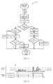
- FIG. 1shows a flow diagram of a capacitance sensing system operation 100 according to one embodiment.
- a system operation 100can include a listening operation 102 , a no local noise processing path 104 , and a local noise processing path 106 .
- a listening operation 102can monitor a sense network 108 for noise.
- a sense network 108can include multiple electrodes for sensing a capacitance in a sensing area.
- a sense network 108can be a mutual capacitance sensing network having transmit (TX) electrodes that can be driven with a transmit signal, and receive (RX) electrodes coupled to the TX electrodes by a mutual capacitance.
- TXtransmit
- RXreceive
- a listening operation 102can use the same electrodes used for capacitance sensing (e.g., touch position detection) for noise detection. In a very particular embodiment, a listening operation 102 can monitor all RX electrodes for noise. In an alternate embodiment, a listening operation 102 can monitor all RX electrodes in a noise listening operation. In yet another embodiment, a listening operation 102 can monitor both TX and RX electrodes in a listening operation.
- a listening operation 102can compare detected noise to one or more threshold values to make a determination on the presence of noise. If noise is determined to be present (Noise), a local noise processing path 106 can be followed. In contrast, if no noise is determined to be present (No Noise), a no local noise processing path 104 can be followed.
- Processing paths 104 and 106show how sense signals derived from sense network 108 can be acquired and filtered.
- a no local noise processing path 104can acquire sense values from a sense network 108 with a standard scan 110 and non-local filtering 112 .
- a standard scan 110can sample electrode values to generate sense values using a set number of sample operations and/or a set duration.
- Non-local filtering 112can provide filtering that is not directed at local noise events, such as those arising from external noise.
- non-local filtering 112can include common mode type filtering that filters for noise common to all sense electrodes.
- a local noise processing path 106can address the adverse affects of local noise, like that arising from external noise.
- a local noise processing path 106can acquire sense values from a sense network 108 with an extended scan 114 and local filtering 116 .
- An extended scan 114can sample electrode values with a larger number of sample operations and/or a longer duration than the standard scan 110 .
- local filtering 116can provide filtering to remove local noise events, such as those arising from external noise.
- local filtering 116can include median filtering.
- a processing of capacitance sense signalscan switch from a standard scan time and non-local filtering to an increased scan time and local filtering.
- FIG. 2shows a flow diagram of a capacitance sensing system operation 200 according to another embodiment.
- system operation 200can be one implementation of that shown in FIG. 1 .
- FIG. 2further shows a noise alarm operation 218 and touch position calculation operation 220 .
- a listening operation 202can include listener scanning 222 , listener common mode filtering (CMF) 224 , and noise detection 226 .
- Listener scanning 222can include measuring signals on multiple electrodes of sense network 208 . Scanning (noise signal acquisition) times can be selected based on sense network and expected noise source(s).
- a listener CMF 224can filter for noise common to all electrodes being scanned. Such filtering can enable external type noise (noise local to a subset of the scanned electrodes) to pass through for noise detection 226 .
- Noise detection 226can establish whether any detected noise exceeds one or more thresholds. In the embodiment shown, if noise is below a first threshold, noise detection 226 can activate a “No Noise” indication. If noise is above a first threshold, noise detection 226 can activate a “Noise” indication. If noise is above a second threshold, greater than the first threshold, noise detection 226 can activate a “High Noise” indication.
- processingcan proceed according to no local noise processing path 204 .
- a processing path 204can utilize a standard scanning 210 , which in the particular embodiment shown can include 8 subconversions per electrode.
- a subconversioncan be an elementary signal conversion event, and can reflect demodulation and/or integration results for one or more full input signal periods.
- Such processingcan further include a CMF filtering 212 of values sensed on multiple electrodes. Such values can then be subject to baseline and difference calculations 228 , which can determine and difference between current sense values and baseline values. A sufficiently large difference can indicate a touch event.
- processingcan proceed according to local noise processing path 206 .
- Local noise processing 206can increase signal acquisition time with an extended scanning 214 that utilizes 16 subconversion (i.e., doubles a scanning time versus the no noise case).
- a processing path 206can further include non-CMF filtering 216 that can filter for external noise events affecting a local set of electrodes.
- non-CMF filtering 216can include median filtering 216 - 0 and non-linear filtering 216 - 1 . Resulting filtered sense values can then be subject to baseline and difference calculations 228 , like that described for the no local noise processing path 204 .
- processingcan include activation of an alarm indication 218 .
- An alarm indication 218can inform a user and/or a system that noise levels are high enough to result in erroneous capacitance sensing results.
- a warningcan be a visual warning on a display associated with the sense network 208 (e.g., a touchscreen display).
- warningsmay include various other indication types, including but not limited to: a different type of visual alarm (e.g., LED), an audio alarm, or a processor interrupt, to name just a few.
- processingin response to a “High Noise” indication, processing may also proceed according to local noise processing path 206 .
- capacitance sense processingcould be interrupted, or additional filtering or signal boosting could occur.
- Operation 200can also include touch position calculations 220 .
- Such actionscan derive positions of touch events from sense values generated by processing paths 204 and 206 .
- Touch position values generated by calculations 220can be provided to a device application, or the like.
- a listening circuitcan include common mode filtering of sense electrodes to listen for localized noise events, such as external noise from a device charger or the like.
- Sense signalscan be filtered based on sensed noise values and/or an alarm can be triggered if noise levels exceed a high threshold value.
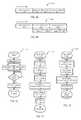
- a capacitance sensing systemcan include a sense network 308 , switch circuits 332 , an analog-to-digital converter (ADC) 334 , a signal generator 336 , and a controller 330 .
- a sense network 308can be any suitable capacitance sense network, including a mutual capacitance sensing network, as disclosed herein.
- a sense network 308can include multiple sensors (e.g., electrodes) for sensing changes in capacitance.
- Switch circuits 332can selectively enable signal paths, both input and output signal paths, between a sense network 308 and a controller 330 . In the embodiment shown, switch circuits 332 can also enable a signal path between a signal generator 336 and sense network 308 .
- An ADC 334can convert analog signals received from sense network 308 via switching circuits 308 into digital values.
- An ADC 334can be any suitable ADC, including but not limited to a successive approximation (SAR) ADC, integrating ADC, sigma-delta modulating ADC, and a “flash” (voltage ladder type) ADC, as but a few examples.
- SARsuccessive approximation
- ADCintegrating ADC
- sigma-delta modulating ADCsigma-delta modulating ADC
- flashvoltage ladder type
- a signal generator 336can generate a signal for inducing sense signals from sense network 308 .
- a signal generator 336can be a periodic transmit (TX) signal applied to one or more transmit electrodes in a mutual capacitance type sense network.
- TX signalcan induce a response on corresponding RX signals, which can be sensed to determine whether a touch event has occurred.
- a controller 330can control capacitance sensing operations in a system 300 .
- a controllercan include sense control circuits 338 , filter circuits 311 , position determination circuits 320 , and noise listening circuits 302 .
- controller 330 circuitse.g., 338 , 311 , 320 and 302
- controller 330 circuitscan be implemented by a processor executing instructions. However, in other embodiments, all or a portion of such circuits can be implemented by custom logic and/or programmable logic.
- Sense control circuits 338can generate signals for controlling acquisition of signals from sense network 308 .
- sense control circuits 338can activate switch control signals SW_CTRL applied to switching circuits 332 .
- mutual capacitance sensingcan be employed, and sense control circuits 338 can sequentially connect a TX signal from signal generator 336 to TX electrodes within sense network 308 . As each TX electrode is driven with the TX signal, sense control circuits 338 can sequentially connect RX electrodes to ADC 334 to generate digital sense values for each RX electrode. It is understood that other embodiments can use different sensing operations.
- Noise listening circuits 302can also control acquisition of signals from sense network 308 by activating switch control signals SW_CTRL. However, noise listening circuit 302 can configure paths to sense network 308 to enable the detection of local noise, as opposed to touch events. In a particular embodiment, noise listening circuit 302 can isolate signal generator 336 from sense network 308 . In addition, multiple groups of electrodes (e.g., RX, TX or both) can be simultaneously connected to ADC 334 . Noise listener 302 can filter such digital values and then compare them to noise thresholds to determine a noise level. Such actions can include arriving at “No Noise”, “Noise” and optionally “High Noise” determinations as described for FIG. 2 .
- a controller 330can alter capacitance sensing operations.
- signal acquisition timescan be increased (e.g., subconversions increased) and filtering can be changed (e.g., median filtering instead of common mode filtering).
- Filter circuits 311can filter sense values generated during sense operations and noise detection operations.
- filter circuits 311can enable one or more types of median filtering 316 and one or more types of CMF 312 . It is understood that filter circuits can be digital circuits operating on digital values representing sensed capacitance.
- filter circuits 311can include a processor creating sense value data arrays from values output from ADC 334 . These arrays of sense values can be manipulated according to one or more selected filtering algorithm to create an output array of filtered sense values. A type of filtering employed by filter circuits 311 can be selected based on detected noise levels.
- Position determination circuits 320can take filtered sense values to generate touch position values (or no detected touches) for use by other processes, such as applications run by a device.
- a capacitance sensing systemcan include listening circuits for detecting noise values and digital filters, selectable based on a detected noise level.
- a capacitance sensing systemaccording to another embodiment is shown in a block schematic diagram and designated by the general reference character 400 .
- a noise listening operationcan vary based on a system condition.
- noise listeningcan be enabled or disabled based on the presence of a charger.
- a system 400can include sections like those of FIG. 3 , and such sections can have the same or equivalent structures as FIG. 3 .
- FIG. 4differs from FIG. 3 in that it also shows a charger interface 440 , battery interface 448 , power control circuits 441 , and application(s) 446 .
- a charger interface 440can enable power to be provided to system 400 that charges a battery via a battery interface 448 .
- a charger interface 440can be a physical interface that creates a mechanical connection between a charger 442 and the system 400 .
- such a physical connectioncan include a ground connection that can give rise to injected current as represented in FIG. 22 .
- alternate embodimentscan include wireless charging interfaces.
- Power control circuits 441can activate a charging indication (Charging) when a charger 442 is coupled to a system 400 , and thus can present an external noise source. In addition, power control circuits 441 can control charging operations of a battery via batter interface 448 .
- ChargingCharging
- power control circuits 441can control charging operations of a battery via batter interface 448 .
- listening circuits 402 ′can vary listening operations in response to a charger indication (Charging). In one embodiment, if the Charging indication is inactive, indicating that a charger 442 is not present, listening circuits 402 ′ can be disabled. If the Charging indication is active, listening circuits 402 ′ can be enabled. However in other embodiments, listening circuits 402 ′ can switch between different types of listening operations based on a charger indication (Charging).
- a chargercan be one source of noise
- other types of power supplies for a devicecan be a source of noise (e.g., AC/DC converters within such devices).
- some devicescan be connected to a computer with its own external power supply, or even a charger within an automobile.
- Application(s) 446can be programs executable by a system 400 utilizing position values from position determination circuits 420 .
- a capacitance sensing systemcan vary listening circuit operations that detect noise values based on a physical condition of the system.
- FIG. 5a capacitance sensing system according to a further embodiment is shown in a block schematic diagram and designated by the general reference character 500 .
- an alarmcan be generated when noise exceeds a threshold value.
- a system 500can include sections like those of FIG. 3 , and such sections can have the same or equivalent structures as FIG. 3 .
- FIG. 5differs from FIG. 3 in that is also shows an alarm circuit 518 , a display 548 and application(s) 546 .
- a listening circuit 502can provide a noise level indication to alarm circuit 516 when detected noise is determined to exceed a high threshold.
- An alarm circuit 516can activate one or more alarms, when the high noise threshold is exceeded.
- alarm circuit 516can provide an alarm (Alarm-Display) to display 548 .
- a display 548can show a visual alarm indicating that touch inputs are affected by noise (e.g., touch inputs will not be accepted, etc.).
- display 548 and sense network 508can be a touchscreen assembly (i.e., sense network 508 is physically overlaid on display 548 ).
- an alarm circuit 516can provide an alarm to application(s) 546 . Such applications can then alter execution and/or generate their own alarm. Further, as noted in conjunction with FIG. 2 , an alarm can take various other forms (e.g., an interrupt, or the like).
- a capacitance sensing systemcan generate an alarm for a user in the event noise levels exceed a predetermined threshold.
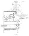
- FIG. 6a capacitance sensing system according to another embodiment is shown in a block schematic diagram and designated by the general reference character 600 .
- the embodiment of FIG. 6shows an implementation utilizing a processor and instructions to provide listening, selectable filtering, and alarm functions.
- a system 600can include switching circuits 632 , controller 630 , a capacitance sense system 678 , oscillator circuits 650 , an ADC 634 , instruction memory 660 , communication circuits 656 , random access memory (RAM) 658 , and a power control circuits 644 .
- Switching circuits 632can provide analog signal paths between a sense network 608 and circuits within a system 600 .
- switching circuits 632can include a number of channels 664 - 0 to - 7 and a channel multiplexer (MUX) 672 . Switching and MUXing operations within switching circuits 632 can be controlled by switch control signals (SW_CTRL) provided by controller 630 .
- Each channel ( 664 - 0 to - 7 )can include a number of input/output (I/O) switches (one shown 666 ) connected to an I/O connection 631 , an I/O MUX 668 , and a sample and hold (S/H) circuit 670 .
- I/Oinput/output
- Each I/O switch ( 666 )can connect a corresponding I/O 631 to a RX path (one shown as 674 ) or a TX path (one shown as 676 ).
- I/O MUX 668can connect one of RX paths 674 within a channel to the corresponding S/H circuit 670 .
- TX paths 676can receive a TX signal.
- a channel MUX 672can selectively connect a S/H circuit 670 within each channel ( 664 - 0 to - 7 ) to ADC 634 .
- An ADC 634can include any suitable ADC as described herein, or an equivalent.
- FIG. 6shows a system 600 connected to mutual capacitance sense network 608 .
- Sense network 608can include TX electrodes formed by TX plates (one shown as 608 - 0 ) and RX plates (one shown as 608 - 1 ).
- TX electrodescan be connected to a TX path 676 , while multiple RX electrodes are connected to corresponding RX paths 674 .
- a controller 630can include a processor 630 - 0 and digital processing circuits 630 - 1 .
- a processor 630 - 0can control operations of digital processing circuits 630 - 1 in response to instructions stored in instruction memory 660 .
- Instruction memory 660can include noise listening instructions 602 , alarm control instructions 618 , and filter instructions 611 .
- Filter instructions 611can include multiple filtering operations, and in the embodiment shown, can include median filter instructions 616 and CMF instructions 612 .
- a controller 630can generate signals that connect multiple I/Os 631 to ADC 634 .
- valuescan be subject to an initial listening CMF operation. Such an operation can be called from filter instructions 611 or be built into noise listening instructions 602 . Resulting values can then be compared to one or more thresholds to determine a noise level. If a noise level exceeds a certain level, a listening circuit 602 can establish capacitance sensing parameters directed to filtering local noise (e.g., an external noise source). In some embodiments, such parameters can include those described for other embodiments, including an increased scan time and/or non-common mode (e.g., median) filtering. In addition, if a noise threshold level is above another certain level, alarm instructions 618 can be called to generate an appropriate alarm.
- Processor 630 - 0alone, or in combination with digital processing circuits 630 - 1 , can perform arithmetic and logic operations for detecting noise and/or filtering sense values.
- Capacitance sensing system 678can include circuits for performing capacitance sensing operations.
- capacitance sensing system 678can include sense control circuits 638 that generate switch control signals for controlling switching circuits 632 .
- capacitance sensing system 678can perform sensing operation based on criteria established by controller 630 .
- a controller 630can vary a sensing time (e.g., number of subconversions) based on a noise level.
- oscillator circuits 650can generate signals for controlling timing of operations within system 600 .
- a TX signal presented at TX paths 676can be provided by, or derived from signals generated by oscillator circuits 650 .
- Communication circuits 656can provide capacitance sensing results to other systems or circuits of a device containing the capacitance sensing system 600 .
- RAM 658can be provided to enable processor 630 - 0 to execute arithmetic operations and/or temporarily store instruction data.
- a RAM 658can store sense value matrices that are manipulated by processor 630 - 0 to detect noise and/or filter capacitance sense values.
- Power control circuits 644can generate power supply voltages for various portions within a system 600 .
- power control circuits 644provide a charging indication, like that described for FIG. 4 , which can indicate when a charger is coupled to the system 600 .
- a processor 630 - 0can then bypass noise listening instructions 602 in the absence of a charger, or may select between multiple listening algorithms based on the presence or absence of a charger.
- FIG. 6also shows timer circuits 652 and programmable circuits 654 .
- Timer circuits 652can provide timing functions for use by various sections of system 600 .
- Programmable circuits 654can be programmed with configuration data to perform custom function. In the embodiment shown, programmable circuits 654 can include programmable digital blocks.
- a system 600can be implemented with a PSoC®3 type programmable system-on-chip fabricated by Cypress Semiconductor Corporation of San Jose, Calif. U.S.A.
- a capacitance sensing systemcan include a processor that can execute any of: noise listening instructions, noise alarm instructions, median filtering, and CMF.
- FIG. 7is a schematic diagram showing a noise listening configuration for a mutual capacitance sense network 708 according to an embodiment.
- a sense network 708can include first electrodes (one shown as 780 ) and second electrodes (one shown as 782 ) coupled to one another by a mutual capacitance Cm.
- Noise, represented by noise voltage source 784 , on one or more first electrodes 780can induce a noise signal (Ix) by mutual capacitance coupling.
- first electrodes 780can be TX electrodes and second electrodes 782 can be RX electrodes. However, the TX electrodes are not driven by any system generated TX signal, but rather are used to detect noise.
- FIGS. 8A and 8Bshow different noise listening configurations according to embodiments.
- FIG. 8Ashows a noise listening configuration for a mutual capacitance sense network 808 according to one embodiment.
- Sense network 808can include TX electrodes (one highlighted as 880 ) arranged in one direction and RX electrodes (one highlighted as 882 ) arranged in another direction.
- sets of RX electrodes 882(in this embodiment, sets of two) can be connected to RX paths (RX 0 to RX 7 ) for noise listening operations.
- TX electrodes 880can be connected to ground.
- FIG. 8Bshows a noise listening configuration for a mutual capacitance sense network 808 according to another embodiment.
- Sense network 808can have the structure shown in FIG. 8A .
- RX electrodes 882 and TX electrodes 880can be commonly connected to a same RX path.
- RX paths RX 0 to RX 3can be connected to two RX electrodes 882 and one TX electrode 880
- RX paths RX 4 to RX 7can be connected to two RX electrodes 882 and two TX electrodes 880 .
- RX and/or TX electrodes of a mutual capacitance sense networkcan be connected to capacitance sensing inputs to listen for noise while a TX signal is prevented from being applied to the network.
- FIGS. 9A and 9Bshow listening operations according to embodiments.
- FIG. 9Ashows a listening operation 900 -A having serial noise listening operations. Progression of time is shown by arrow “t”.
- a listening operation 900 -Acan begin with a listening scanning action 902 .
- Such an actioncan include acquiring capacitance values across multiple sensors (e.g., electrodes).
- such a stepcan include establishing connections to a mutual capacitance sense array like that shown in FIG. 8A or 8 B.
- acquired valuescan be subject to listening CMF 904 .
- a listening CMFcan include common mode filtering that can filter out noise common to all electrodes and thus help isolate local noise (e.g., external type noise). Filtered sense values can then be subject to a noise detection action 906 .
- Such an actioncan compare sensed capacitance levels to one or more limits to determine a noise level.
- a listening operation 900 -Acan repeat, performing another listening scanning action 902 .
- FIG. 9Bshows a listening operation 900 -B having pipelined noise listening operations. Progression of time is shown by arrow “t”.
- a listening operation 900 -Bcan begin with a listening scanning action 902 - 1 , which can acquire a first set of raw capacitance values.
- a next listening scanning operation 902 - 2can begin.
- the first set of raw data acquired with the first scanning action 902 - 1can be common mode filtered 904 - 1 and subject to noise detection 906 - 1 .
- FIG. 10shows a noise listening operation 1000 according to one embodiment in a flow diagram.
- An operation 1000can include a scanning initialization 1010 .
- a scanning initializationcan configure connections to a sense network to enable the sensing of noise across multiple channels.
- Such an initializationcan include changing sense network configurations from a standard touch sensing configuration to a noise listening configuration.
- an operation 1000can, in parallel, perform noise scanning 1012 and noise detection 1014 .
- Noise scanning 1012can include acquiring sense values from electrodes.
- Noise detection 1014can include detecting noise from previously acquired sense values.
- a noise listening operation 1000can restore a sense network to a normal state 1018 .
- a normal statecan be that utilized for standard sensing operations (e.g., touch sensing).
- FIG. 11shows a scanning initialization operation 1100 according to an embodiment.
- a scanning initialization operation 1100can be one particular implementation of that shown as 1010 in FIG. 10 .
- Scanning initialization operation 1100can be a scanning initialization operation for a mutual capacitance sense network.
- An operation 1100can include disabling any circuits utilized in standard scanning operations that could interfere with noise detection ( 1120 ).
- an action 1120can include turning off current digital-to-analog converters (iDACs) connected to a sense network.
- RX pathscan be configured as high impedance inputs ( 1122 ). RX paths can then be connected to input channels ( 1124 ).
- a signal acquisition time(e.g., scan time) can then be set that is suitable for the noise to be detected.
- such an actioncan include setting a number of subconversions ( 1126 ) to a predetermined value. All active channels can then be turned on ( 1128 ). Such an action can enable electrodes to be connected to capacitance sensing circuits. A scan can then start ( 1130 ). Such an action can acquire raw sense values to enable noise to be detected. A scanning initialization operation 1100 can then end.
- FIG. 12shows a restore-to-normal operation 1232 according to an embodiment.
- a restore-to-normal operation 1232can be one particular implementation of that shown as 1018 in FIG. 10 .
- Restore-to-normal operation 1232can include disconnecting all RX paths from input channels ( 1234 ). Such RX channels can then be configured for standard sensing operations ( 1236 ).
- a signal acquisition timee.g., scan time
- a signal acquisition timecan then be returned to that utilized for standard sensing operations ( 1238 ).
- such an actioncan include setting a number of subconversions.
- An operation 1232can include enabling previously disabled circuits utilized in standard scanning operations ( 1240 ).
- an action 1240can include turning on iDACs.
- a restore to normal operation 1232can then end.
- FIG. 13shows a noise detection operation 1314 according to an embodiment.
- a noise detection operation 1314can be one particular implementation of that shown as 1014 in FIG. 10 .
- a noise detection operation 1314can include a CMF operation 1340 .
- Such filteringcan remove noise common to electrodes and thus can improve a signal from any local noise (i.e., external noise).
- Operation 1314can then determine a noise value.
- determining a noise valuecan include finding maximum and minimum values from the CMF filtered values ( 1342 ), and then determining the difference between such values ( 1344 ).
- a noise valuecan then be compared to a first threshold ( 1346 ). If a noise value is above a first threshold (Yes from 1346 ), a listening timeout value can be reset ( 1348 ) and a noise level can be set to a first value (ON) ( 1350 ). If noise has been determined to above a first threshold, the noise can also be compared to a second threshold ( 1352 ). If a noise value is above a second threshold (Yes from 1352 ), a noise level can be set to a second value (Alarm) ( 1354 ). An operation can then end 1366 . If a noise value is below a second threshold (No from 1352 ), an operation can also end 1366 .
- a noise detection operation 1314can determine if a noise level should be returned to a zero value (i.e., no noise). In the embodiment shown, if a noise level can be checked to see if it still indicates a high noise state (i.e., ON or Alarm) ( 1356 ). If no elevated noise is indicated (No from 1356 ) a timeout value can be reset ( 1348 ). If elevated noise is indicated (Yes from 1356 ) a timeout value can be incremented ( 1348 ). The timeout value can then be compared to a limit ( 1362 ). If a timeout value exceeds a limit (Yes from 1362 ), the noise level can be returned to the no noise state ( 1350 ). If a timeout value does not exceed a limit (No from 1362 ), an operation can end 1366 .
- FIG. 14is a timing diagram showing a noise detection operation according to one embodiment.
- FIG. 14includes a waveform NOISE DATA, showing noise sense values acquired by a noise listening operation. Projected onto the NOISE DATA waveform are two noise threshold levels (1 st _Threshold and 2 nd _Threshold).
- FIG. 14also includes a waveform NOISE LEVEL that shows noise levels determined by a noise detection operation.
- NOISE LEVELcan indicate three different noise levels.
- noise valuescan exceed a first threshold.
- a noise detection operationcan set a noise level to ON.
- noise levelscan return to an OFF state.
- noise valuescan exceed a second threshold.
- a noise detection operationcan set a noise level to Alarm.
- noise levelscan return to an OFF state.
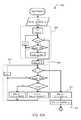
- a local noise filtering operation 1516can be performed on sense data in the event local (i.e., not common mode) noise levels are determined to exceed a certain level.
- An operation 1516can include inputting sense signals ( 1568 ). Such an action can include inputting raw count values generated from an ADC connected to sense electrodes.
- An operation 1516can find a main signal ( 1570 ). Such an action can locate a potential touch location. As will be recalled, local noise can present around touch locations.
- a main signalcan correspond to a sensor having a highest response (which would, in the absence of noise, indicate a touch).
- An operation 1516can then scale signals from neighboring sensors to the corresponding main sensor signal ( 1572 ).
- Neighbor sensorscan be sensors physically proximate to the main sensor.
- neighbor sensorscan be sensor on opposing sides of a main sensor.
- a scaling operationcan alter a sense value of a neighbor electrode based on how such an electrode varies from the main when a valid touch event occurs.
- scalingcan be based on a mean value when a touch is present for an electrode.
- a median filtercan be applied with respect to the main signal ( 1574 ). Such an action can include applying a median filter to sense values for electrodes.
- a median filtercan be applied to sensor signals from three consecutive time periods.
- a true touch eventcan provide an increase count value that may be sustained over multiple time periods.
- local noise levelsmay vary in polarity over time.
- a median filter operation(e.g., 1574 ) can be a first type of non-linear filtering that is performed.
- An operation 1516can also include an adaptive jitter filter (AJF) operation ( 1576 ).
- An AJF operatione.g., 1576
- An AJF operationcan be another non-linear filter operation.
- One particular example of an AJF operationis described below in more detail.
- a previous scaling operation(e.g., 1572 ) can be reversed. That is filtered sense values corresponding to neighbor sensors proximate a main sensor can be “unscaled” ( 1578 ). A resulting set of sense values can then be output 1580 .
- FIGS. 16A and 16Bshow a determination of a main signal from electrodes according to an embodiment.
- FIGS. 16A and 16Bshow electrodes physically arranged into two groups, shown as slots 1684 - 0 / 1 .
- a sense operationcan sense capacitance values for different slots with different sense operations.
- slots 1684 - 0 / 1can be RX electrodes coupled to a same TX electrode(s) by a mutual capacitance.
- FIG. 16Ashows a sense operation that determines electrode 1688 has a highest response (count in this embodiment). Consequently, such an electrode can be considered a “main” electrode. Electrodes 1686 adjacent to main electrode 1688 can be considered neighbor electrodes. Sense values corresponding to neighbor electrodes 1686 can be scaled with respect to a sense value for main electrode.
- FIG. 16Bshows a sense operation in which main electrodes 1688 occur on ends of adjacent slots 1684 - 0 / 1 .
- a neighbor electrode 1686 for each main electrodecan be an electrode in a different slot.
- FIGS. 17A and 17Ban AJF operation 1700 according to one embodiment is shown in flow diagram.
- An AJFcan be one particular implementation of that shown as 1576 in FIG. 15 .
- An AJF operation 1700can perform filtering on a subset of electrodes based on average difference of such electrodes over time.
- FIGS. 17A and 17Bare different portions of a flow diagram, with connections between the two shown as circled letters “a” and “b”.
- an AJF operation 1700can include inputting arrays of current signal values, and previously generated filtered signal values ( 1702 ). In the embodiment shown, this can include inputting values Msig ⁇ 1 ⁇ 0 . . . k ⁇ which can be previous filtered values generated by an AJF operation 1700 for an electrode set (e.g., a slot), values Sig ⁇ 1 ⁇ 0 . . . k ⁇ which can be previously input sense values for the same electrode set (which in some embodiments can include scaling and/or median filtering), and values Sig ⁇ 0 . . . k ⁇ which can be current input sense values for the same electrode set.
- an electrode sete.g., a slot
- values Sig ⁇ 1 ⁇ 0 . . . k ⁇which can be previously input sense values for the same electrode set (which in some embodiments can include scaling and/or median filtering)
- values Sig ⁇ 0 . . . k ⁇which can be current input sense values for the same electrode set.
- Various valuescan be initialized to zero, including a positive disparity value sdp, a negative disparity value sdn, and iteration count values i and it ( 1704 ).
- a positive disparity value sdpcan represent the degree of correlation in a positive change from a previous sense value set and current a sense value set.
- a negative disparity value sdncan represent a same correlation, but in the other (i.e., opposite polarity) direction.
- An operation 1700can determine a difference between previous sense signals and current sense signals ( 1706 ).
- an array Mdiff ⁇ 0 . . . k ⁇can be created that holds such values (referred to herein as difference values).
- An operation 1700can then generate positive and negative disparity values utilizing such difference values ( 1708 ).
- such an actioncan include determining if a difference between a previous sense value and its current level is positive, negative, or zero. A positive value will increase a positive disparity for the electrode set. Similarly, a negative value will decrease a negative disparity for the electrode set. In the embodiment shown, no difference in values (zero) can result in both positive and negative disparity values being increased.
- an operationcan then calculate an average sum of the differences between sense signal sets (i.e., current and previous set) ( 1710 ).
- a function “fix”can remove a fractional part of a number ( 1711 ).
- Such an average valueis shown as th_av in the embodiment of FIG. 17 . If an average difference (th_av) is above a threshold value (n from 1712 ), filtering can stop, and current set of input values Sig ⁇ 0 . . . k ⁇ can be saved as filter values for a next filter operation and can be output as filtered values ( 1718 , 1722 , 1724 ).
- a threshold checkcan account from a multi-touch event occurring on the set of electrodes.
- disparity valuescan be compared against correlation limits ( 1714 ). If either (i.e., positive or negative) disparity value is sufficiently small (n from 1714 ) filtering can once again end, with the current set of input values Sig ⁇ 0 . . . k ⁇ can be saved as filter values for a next filter operation and output as filtered values ( 1718 , 1722 , 1724 ).
- an average difference value th_avcan be compared against a minimum value (in this case 0) ( 1716 ). If there is little difference between sense signal sets (y from 1716 ), a current signal sense value set and previous filtered sense value set can be averaged to create a current filtered sense value set ( 1720 ). This set can be saved as filter values for a next filter operation and output as filtered values ( 1718 , 1722 , 1724 ).
- an operation 1700can call a weighting function 1726 .
- a weighting functioncan increase sense values when a limited number of sense values in a set exceed a weighing threshold.
- a weighting functionaccording to one particular embodiment will be described in more detail below.
- a weighting functioncan return a weighting value (delta_av) that can be used to weight sense values in a filtered set.
- filteringcan stop, and current set of input values Sig ⁇ 0 . . . k ⁇ can be saved as filter values for a next filter operation and output as filtered values ( 1718 , 1722 , 1724 ).
- a weighting functionprovides a weighting value (i.e., delta_av ⁇ 0) (n from 1728 )
- an operationcan selectively weight current sense values based on polarities of a difference value and the weighting value (delta_av).
- delta_ava weighting value for an electrode
- the sense valuemay not be weighted.
- a magnitude of difference valuecan be compared to the weighting value ( 1732 ). If a magnitude of a difference is less than that of a weighting value (n from 1732 ), a multi-pass value can be checked to determine if the present operation is an initial pass ( 1734 ). If it is an initial weighting pass (n from 1734 ), an operation 1700 can continue to a next value of the set ( 1738 ). However, if it is a follow on weighting pass (y from 1734 ), a current value can be set to a previous filtered value, and an operation 1700 can continue to a next value of the set ( 1738 ).
- the weighting valuecan be subtracted from the current value ( 1740 ), and an operation 1700 can continue to a next value of the set ( 1738 ).
- a difference setcan be created from the weighted values ( 1742 ).
- a multi-pass valuecan then be checked to determine if the present operation is a last pass ( 1744 ). If the operation is not a last pass (y from 1744 ), a weighting function can be called again with the updated values. If the operation is a last pass (n from 1744 ), a current set of filtered values can be saved as filter values for a next operation and output as filtered values ( 1718 , 1722 , 1724 ).
- a weighting function 1800can be one particular implementation of that shown as 1726 in FIG. 17 .
- a weighting function 1800can weight sense values in a set of electrodes when limited numbers of electrodes in the set exceed a weight threshold.
- FIGS. 18A and 18Bare different portions of a flow diagram, with a connection between the two shown as circled letter “a”.
- a weighting function 1800can include inputting current filtered values Msig ⁇ 0 . . . k ⁇ and difference values Mdiff ⁇ 0 . . . k ⁇ ( 1846 ). A function 1800 can then examine a filtered value for each electrode in a set to see if it exceeds a weighting threshold (WTH). Each time a sense value exceeds a weighting threshold (WTH) a range value can be incremented ( 1848 ). Thus, a range value (range) can represent how many electrodes in a set exceed WTH.
- a weighting valuecan be initialized ( 1849 ).
- an average of the valuescan be generated 1852 .
- fractional portions of weighting valuescan then be removed ( 1853 ).
- a weighting functioncan end, and a the weighting value (zero) can be provided as an output weighting value ( 1856 ) (for use in the AJF).
- a weighting valueis positive, a maximum difference value (Max) from the set of difference values can be determined ( 1856 ). If a weighting value (delta_av) is greater than a maximum value (Max), the weighting value can be set to the maximum value ( 1858 ).
- a weighting valueis negative, a minimum value (Min) from the set of difference values can be determined ( 1860 ). If a weighting value (delta_av) is greater than a minimum value (Min), the weighting value can be set to the minimum value ( 1862 ).
- a weighting value (delta_av)can then be bounded by a high limit value DF_MAX and low limit value DF_MIN ( 1864 ). If a weighting value (delta_av) is greater than high limit, it can be set to the high limit. Similarly, if a weighting value (delta_av) is less than low limit, it can be set to the low limit.
- the resulting weighting valuecan then be provided as an output weighting value ( 1856 ) (for use in the AJF).
- FIGS. 17A to 18Bshow an AJF and weighting function according to a very particular embodiment. Alternate embodiments can realize such operations, or equivalent operation, with other circuits and/or architectures.
- FIG. 19is a flow diagram showing another implementation of an AJF filter and weighting function like that shown in FIGS. 17A to 18B .
- FIG. 19shows processing 1900 that includes a first section 1966 that can generate an average difference value (th_av), a positive disparity value (sdp), and negative disparity value (sdn), as described for FIG. 17A .
- a second section 1970can generate a weighting value (delta_av) like that described for FIGS. 18 A/B.
- a third section 1968can generate filter output values as shown in FIG. 17B .
- a median filter 2000that can be included in the embodiments is shown in a flow diagram.
- a median filter 2000can include inputting a set of sense values from consecutive sample periods (i.e., a sample window) ( 2003 ).
- a sample windowis three.
- a median of the three valuescan be determined, and then provided as an output value ( 2005 ).
- Embodimentscan be utilized in capacitance sense systems to reduce the adverse affects of noise local to a subset of all electrodes, such as that arising from external noise sources.
- Embodimentscan improve capacitance sensing of a device when it is coupled to a charging device by filtering charger noise coupled to a touch object (e.g., finger).
- a touch objecte.g., finger
Landscapes
- Engineering & Computer Science (AREA)
- General Engineering & Computer Science (AREA)
- Theoretical Computer Science (AREA)
- Physics & Mathematics (AREA)
- General Physics & Mathematics (AREA)
- Human Computer Interaction (AREA)
- Position Input By Displaying (AREA)
- Telephone Function (AREA)
- Geophysics And Detection Of Objects (AREA)
- Measurement And Recording Of Electrical Phenomena And Electrical Characteristics Of The Living Body (AREA)
Abstract
Description
kA=(BTmean/ATmean),kC=(BTmean/CTmean)
where kAis a scaling factor for a count value from an electrode A which is a neighbor of an electrode B, kCis a scaling factor for a count value from an electrode C which is a neighbor of an electrode B opposite electrode A, and ATmean, BTmean, and CTmeanare mean sense values derived from touches to such electrodes.
Claims (17)
Priority Applications (2)
| Application Number | Priority Date | Filing Date | Title |
|---|---|---|---|
| US13/247,951US9128570B2 (en) | 2011-02-07 | 2011-09-28 | Noise filtering devices, systems and methods for capacitance sensing devices |
| US14/848,237US9841840B2 (en) | 2011-02-07 | 2015-09-08 | Noise filtering devices, systems and methods for capacitance sensing devices |
Applications Claiming Priority (2)
| Application Number | Priority Date | Filing Date | Title |
|---|---|---|---|
| US201161440327P | 2011-02-07 | 2011-02-07 | |
| US13/247,951US9128570B2 (en) | 2011-02-07 | 2011-09-28 | Noise filtering devices, systems and methods for capacitance sensing devices |
Related Child Applications (1)
| Application Number | Title | Priority Date | Filing Date |
|---|---|---|---|
| US14/848,237ContinuationUS9841840B2 (en) | 2011-02-07 | 2015-09-08 | Noise filtering devices, systems and methods for capacitance sensing devices |
Publications (2)
| Publication Number | Publication Date |
|---|---|
| US20120200524A1 US20120200524A1 (en) | 2012-08-09 |
| US9128570B2true US9128570B2 (en) | 2015-09-08 |
Family
ID=46600334
Family Applications (2)
| Application Number | Title | Priority Date | Filing Date |
|---|---|---|---|
| US13/247,951Active2031-12-09US9128570B2 (en) | 2011-02-07 | 2011-09-28 | Noise filtering devices, systems and methods for capacitance sensing devices |
| US14/848,237Active2031-12-17US9841840B2 (en) | 2011-02-07 | 2015-09-08 | Noise filtering devices, systems and methods for capacitance sensing devices |
Family Applications After (1)
| Application Number | Title | Priority Date | Filing Date |
|---|---|---|---|
| US14/848,237Active2031-12-17US9841840B2 (en) | 2011-02-07 | 2015-09-08 | Noise filtering devices, systems and methods for capacitance sensing devices |
Country Status (4)
| Country | Link |
|---|---|
| US (2) | US9128570B2 (en) |
| KR (1) | KR20140026377A (en) |
| CN (1) | CN102934061B (en) |
| WO (1) | WO2012108911A1 (en) |
Cited By (6)
| Publication number | Priority date | Publication date | Assignee | Title |
|---|---|---|---|---|
| US20150309618A1 (en)* | 2014-04-25 | 2015-10-29 | Synaptics Incorporated | Weighting for display noise removal in capacitive sensors |
| US10088954B2 (en) | 2016-08-11 | 2018-10-02 | Synaptics Incorporated | Object filter |
| US10095363B2 (en) | 2016-03-28 | 2018-10-09 | Synaptics Incorporated | Capacitive sensing with high pass filtering for segmentation |
| US11486081B2 (en) | 2018-03-07 | 2022-11-01 | Electrolux Appliances Aktiebolag | Laundry appliance with user sensing functionality |
| US11531424B2 (en) | 2017-09-07 | 2022-12-20 | Cypress Semiconductor Corporation | Nano-power capacitance-to-digital converter |
| US20230185405A1 (en)* | 2020-05-06 | 2023-06-15 | Chipone Technology (Beijing) Co., Ltd. | Method and device for adjusting touch capacitance data, electronic device, and storage medium |
Families Citing this family (72)
| Publication number | Priority date | Publication date | Assignee | Title |
|---|---|---|---|---|
| CN102884496B (en)* | 2010-02-26 | 2017-06-30 | 辛纳普蒂克斯公司 | Modify demodulation to avoid interference |
| WO2012108911A1 (en) | 2011-02-07 | 2012-08-16 | Cypress Semiconductor Corporation | Noise filtering devices, systems and methods for capacitance sensing devices |
| KR101915259B1 (en)* | 2011-09-09 | 2018-11-05 | 삼성전자 주식회사 | Touch screen sensor integrated circuit, method thereof, and system having the same |
| US8810544B2 (en)* | 2011-10-13 | 2014-08-19 | Himax Technologies Limited | Touch sensing method and electronic apparatus using the same |
| KR20130063131A (en)* | 2011-12-06 | 2013-06-14 | 삼성전자주식회사 | Method and apparatus for configuring touch sensing parameter |
| US10197609B2 (en) | 2012-01-09 | 2019-02-05 | L&P Property Management Company | Capacitive sensing for automated furniture |
| US10555615B2 (en) | 2012-01-09 | 2020-02-11 | L&P Property Management Company | Calibration of detection features for automated furniture |
| US10197259B2 (en) | 2012-01-09 | 2019-02-05 | L&P Property Management Company | Standalone capacitance sensor for furniture |
| US10334960B2 (en) | 2012-01-09 | 2019-07-02 | L&P Property Management Company | Drop-in occupancy detection component for furniture |
| US9337831B2 (en) | 2012-01-09 | 2016-05-10 | L&P Property Management Company | Capacitive wire sensing for furniture |
| US10048662B2 (en)* | 2012-01-09 | 2018-08-14 | L&P Property Management Company | Characterization and calibration for automated furniture |
| JP5490828B2 (en)* | 2012-01-10 | 2014-05-14 | シャープ株式会社 | Linear system coefficient estimation method, integrated circuit using the same, touch panel system, and electronic device |
| US9444452B2 (en) | 2012-02-24 | 2016-09-13 | Parade Technologies, Ltd. | Frequency hopping algorithm for capacitance sensing devices |
| US9209802B1 (en) | 2012-02-24 | 2015-12-08 | Parade Technologies, Ltd. | Frequency selection with two frequency sets of multiple operating frequencies in a mutual capacitance sensing devices |
| US20130241872A1 (en)* | 2012-03-14 | 2013-09-19 | Texas Instruments Incorporated | Aperature filtering for resistive multi-touch distortions |
| US8432170B1 (en) | 2012-03-14 | 2013-04-30 | Cypress Semiconductor Corporation | Integrated capacitance model circuit |
| JP5383855B2 (en)* | 2012-04-17 | 2014-01-08 | ファナック株式会社 | Motor control device having ΔΣ modulation type AD converter |
| KR101607694B1 (en)* | 2012-06-21 | 2016-03-30 | 엘지디스플레이 주식회사 | Image display device and touch driver |
| US9024643B2 (en)* | 2012-06-28 | 2015-05-05 | Synaptics Incorporated | Systems and methods for determining types of user input |
| US9405401B2 (en)* | 2012-07-12 | 2016-08-02 | Parade Technologies, Ltd. | Edge-by-edge integration and conversion |
| KR101725134B1 (en)* | 2012-08-09 | 2017-04-11 | (주)멜파스 | Apparatus and method for sensing of touch |
| US20140057681A1 (en)* | 2012-08-24 | 2014-02-27 | Motorola Mobility Llc | Adaptive Noise Mitigation for Touch-Screen Displays |
| KR20140045076A (en)* | 2012-10-08 | 2014-04-16 | 삼성전자주식회사 | Method and apparatus for increasing performance of in-cell touch-screen |
| TWI475441B (en)* | 2012-10-19 | 2015-03-01 | Au Optronics Corp | In-cell touch display panel and driving method thereof |
| TWI470502B (en)* | 2012-11-07 | 2015-01-21 | Elan Microelectronics Corp | Foreign object detection method of a touch panel |
| US10067575B2 (en)* | 2012-11-30 | 2018-09-04 | Apple Inc. | Noise correction for stylus applications on tablets and other touch devices |
| KR20140071050A (en)* | 2012-12-03 | 2014-06-11 | 삼성전자주식회사 | Capacitive multi-touch system and method of controlling the same |
| KR101444549B1 (en)* | 2012-12-12 | 2014-09-24 | 삼성전기주식회사 | Method and apparatus for sensing touch input |
| JP5778122B2 (en)* | 2012-12-14 | 2015-09-16 | 株式会社ジャパンディスプレイ | Display device with touch detection function and electronic device including the same |
| CN103019495B (en)* | 2012-12-26 | 2015-10-21 | 深圳贝特莱电子科技有限公司 | A kind of method for Noise measarement in capacitive touch screen and device |
| CN103902116B (en)* | 2012-12-30 | 2017-04-12 | 比亚迪股份有限公司 | Anti-interference method and device for capacitance detection |
| US20140218331A1 (en)* | 2013-02-07 | 2014-08-07 | Au Optronics Corporation | Dynamic power adjustment of level shift for noise rejection in capacitance touch system |
| US9465459B2 (en)* | 2013-02-19 | 2016-10-11 | Blackberry Limited | Electronic device including touch-sensitive display and method of detecting noise |
| US9846185B2 (en) | 2013-02-27 | 2017-12-19 | Texas Instruments Incorporated | Capacitive sensing |
| US8874396B1 (en)* | 2013-06-28 | 2014-10-28 | Cypress Semiconductor Corporation | Injected touch noise analysis |
| WO2015038133A1 (en)* | 2013-09-12 | 2015-03-19 | Intel Corporation | Detecting gestures on the side of a computing device |
| US20150077382A1 (en)* | 2013-09-19 | 2015-03-19 | Inputek Co., Ltd | Touch Circuit Architecture |
| KR20150058712A (en)* | 2013-11-20 | 2015-05-29 | 삼성전자주식회사 | Touch Screen Controller generating single-ended touch signal, Touch Screen System and Operating Method thereof |
| KR102132865B1 (en)* | 2013-12-23 | 2020-07-10 | 엘지디스플레이 주식회사 | Display device and method of drving the same |
| KR101921675B1 (en)* | 2014-01-26 | 2018-11-23 | 후아웨이 디바이스 (둥관) 컴퍼니 리미티드 | Touchscreen interference suppression method and apparatus, and terminal device |
| US9195341B2 (en)* | 2014-02-14 | 2015-11-24 | Texas Instruments Incorporated | Touchscreen controller and method for charger noise reduction through noise shaping |
| WO2015122714A1 (en) | 2014-02-17 | 2015-08-20 | 주식회사 센트론 | Method for removing noise introduced from non-sensing region in touch input sensing device |
| JP6242717B2 (en)* | 2014-03-05 | 2017-12-06 | シナプティクス・ジャパン合同会社 | Semiconductor device and electronic equipment |
| CN104978089B (en)* | 2014-04-09 | 2017-12-19 | 晨星半导体股份有限公司 | Touch sensing circuit and method |
| US9600121B2 (en)* | 2014-04-25 | 2017-03-21 | Synaptics Incorporated | Driving sensor electrodes for noise measurement |
| US10725591B1 (en)* | 2014-04-30 | 2020-07-28 | Cypress Semiconductor Corporation | Passive touch detection for capacitive sense array |
| JP6267060B2 (en)* | 2014-05-30 | 2018-01-24 | Dmg森精機株式会社 | Operating device |
| KR102249651B1 (en) | 2014-07-23 | 2021-05-10 | 주식회사 실리콘웍스 | Touch panel sensing apparatus and controlling apparatus thereof |
| KR102290990B1 (en) | 2014-10-06 | 2021-08-18 | 삼성전자주식회사 | Touch analog front end and touch sensor controller having the same |
| CN104375014B (en)* | 2014-11-21 | 2017-02-22 | 西安交通大学 | Single-frequency overlapping method for power capacitor noise test |
| TWI594152B (en)* | 2015-04-22 | 2017-08-01 | 友達光電股份有限公司 | Touching sensing device |
| US9886136B2 (en)* | 2015-06-22 | 2018-02-06 | Samsung Electronics Co., Ltd. | Touch screen controller using adaptive filter control and touch screen system having the same |
| GB2540768A (en)* | 2015-07-27 | 2017-02-01 | Touchnetix Ltd | Capacitive sensing apparatus and methods |
| TWI592845B (en)* | 2015-08-28 | 2017-07-21 | 晨星半導體股份有限公司 | Method and associated controller for adaptively adjusting touch-control threshold |
| US10013593B2 (en)* | 2015-09-09 | 2018-07-03 | Cypress Semiconductor Corporation | Multiphase fingerprint sensor layout and construction |
| US9645670B2 (en)* | 2015-09-30 | 2017-05-09 | Synaptics Incorporated | Sensing frame averaging for cancelling display noise in simultaneous display and touch sensing |
| EP3159777B1 (en)* | 2015-10-20 | 2024-05-29 | LG Display Co., Ltd. | Method and circuit for driving touch sensors and display device using the same |
| CN105389225A (en)* | 2015-11-25 | 2016-03-09 | 小米科技有限责任公司 | Touch screen reporting point processing method and apparatus |
| US9864466B2 (en) | 2015-12-31 | 2018-01-09 | Synaptics Incorporated | Mitigating common mode display noise using hybrid estimation approach |
| US9817535B2 (en) | 2016-03-07 | 2017-11-14 | Synaptics Incorporated | Mitigating spatially correlated noise in data from capacitive sensors |
| CN106445136B (en)* | 2016-09-20 | 2018-05-04 | 华南理工大学 | Data waveform restoration methods, system and device |
| CN109478115B (en)* | 2016-12-22 | 2022-02-15 | 深圳市汇顶科技股份有限公司 | Noise sensing circuit and touch device |
| US10423277B2 (en)* | 2016-12-30 | 2019-09-24 | Texas Instruments Incorporated | Interference reduction circuit for touch system |
| WO2018148902A1 (en)* | 2017-02-16 | 2018-08-23 | 深圳市汇顶科技股份有限公司 | Button detection method and device |
| WO2019023922A1 (en)* | 2017-08-01 | 2019-02-07 | 深圳市汇顶科技股份有限公司 | Method for determining touch position and touch control chip |
| KR102378749B1 (en) | 2017-09-27 | 2022-03-28 | 현대자동차주식회사 | Input apparatus and control method of the same |
| EP3828673B1 (en)* | 2018-07-26 | 2024-12-11 | Alps Alpine Co., Ltd. | Electrostatic capacitance sensor, control method for same, and program |
| US10515705B1 (en)* | 2018-11-22 | 2019-12-24 | Wuhan Xinxin Semiconductor Manufacturing Co., Ltd. | Removing pump noise in a sensing circuit |
| US11703983B2 (en) | 2020-03-25 | 2023-07-18 | Sensortek Technology Corp | Capacitance sensing circuit |
| US11754616B2 (en) | 2020-05-27 | 2023-09-12 | Taiwan Semiconductor Manufacturing Company Limited | Methods and systems to test semiconductor devices based on dynamically updated boundary values |
| CN112363641B (en)* | 2020-11-24 | 2024-06-21 | Oppo广东移动通信有限公司 | Touch scanning method, TPIC chip, DDIC chip and module |
| CN118519548B (en)* | 2024-07-23 | 2024-11-19 | 深圳贝特莱电子科技股份有限公司 | Scanning method, storage medium and equipment of low-power-consumption touch pad |
Citations (28)
| Publication number | Priority date | Publication date | Assignee | Title |
|---|---|---|---|---|
| US6215477B1 (en) | 1997-10-22 | 2001-04-10 | Smart Technologies Inc. | Touch sensitive display panel |
| US6624835B2 (en) | 2001-01-09 | 2003-09-23 | National Semiconductor Corporation | System and method for noise reduction in touch screen system |
| US6734843B2 (en) | 1994-08-22 | 2004-05-11 | Igt | Reduced noise touch screen apparatus and method |
| US20050122119A1 (en) | 2003-12-05 | 2005-06-09 | Touchram Llc | Low noise proximity sensing system |
| US20060103635A1 (en) | 2004-11-17 | 2006-05-18 | Samsung Electronics Co., Ltd. | Device and method of avoiding noise in touch screen panel |
| US20060267953A1 (en)* | 2005-05-31 | 2006-11-30 | Peterson Richard A Jr | Detection of and compensation for stray capacitance in capacitive touch sensors |
| KR20080013638A (en) | 2006-08-09 | 2008-02-13 | 삼성전자주식회사 | Noise filtering device and method of touch panel |
| KR20080039121A (en) | 2006-10-31 | 2008-05-07 | 엘지전자 주식회사 | Noise reduction device and method of touch sensor |
| US20080285773A1 (en) | 2007-05-17 | 2008-11-20 | Rajeev Nongpiur | Adaptive LPC noise reduction system |
| US20090002343A1 (en) | 2007-06-28 | 2009-01-01 | Brian Land | Systems and methods for impedance stabilization |
| US20090228272A1 (en) | 2007-11-12 | 2009-09-10 | Tobias Herbig | System for distinguishing desired audio signals from noise |
| US20100060610A1 (en) | 2008-09-08 | 2010-03-11 | Tpo Displays Corp. | Sensing circuit for capacitive touch panel |
| US20100079401A1 (en) | 2008-09-26 | 2010-04-01 | Kenneth Lawrence Staton | Differential sensing for a touch panel |
| US20100079402A1 (en) | 2008-09-26 | 2010-04-01 | Apple Inc. | Touch detection for touch input devices |
| KR20100040518A (en) | 2008-10-10 | 2010-04-20 | 엘지전자 주식회사 | Apparatus and method for controlling detection signal of touch sensor |
| US20100097078A1 (en) | 2008-10-22 | 2010-04-22 | Harald Philipp | Noise Handling in Capacitive Touch Sensors |
| US20100172510A1 (en) | 2009-01-02 | 2010-07-08 | Nokia Corporation | Adaptive noise cancelling |
| US20100292945A1 (en)* | 2009-05-13 | 2010-11-18 | Joseph Kurth Reynolds | Capacitive sensor device |
| US20110061947A1 (en)* | 2009-09-11 | 2011-03-17 | Christoph Horst Krah | Power Management for Touch Controller |
| US20110115729A1 (en) | 2009-10-20 | 2011-05-19 | Cypress Semiconductor Corporation | Method and apparatus for reducing coupled noise influence in touch screen controllers |
| US20110120784A1 (en)* | 2009-11-21 | 2011-05-26 | Freescale Semiconductor, Inc. | Methods and apparatus for performing capacitive touch sensing and proximity detection |
| US20110157077A1 (en)* | 2008-06-25 | 2011-06-30 | Bradley Martin | Capacitive sensor system with noise reduction |
| US20110157067A1 (en) | 2009-12-31 | 2011-06-30 | Motorola, Inc. | Duty cycle modulation of periodic time-synchronous receivers for noise reduction |
| US8027743B1 (en) | 2007-10-23 | 2011-09-27 | Adobe Systems Incorporated | Adaptive noise reduction |
| US20110254802A1 (en)* | 2010-04-15 | 2011-10-20 | Harald Philipp | Noise reduction in capacitive touch sensors |
| US20120013565A1 (en)* | 2010-07-16 | 2012-01-19 | Perceptive Pixel Inc. | Techniques for Locally Improving Signal to Noise in a Capacitive Touch Sensor |
| US20120056841A1 (en)* | 2010-09-02 | 2012-03-08 | Texas Instruments Incorporated | Touch-sensitive interface and method using orthogonal signaling |
| US20120062474A1 (en)* | 2010-09-15 | 2012-03-15 | Advanced Silicon Sa | Method for detecting an arbitrary number of touches from a multi-touch device |
Family Cites Families (42)
| Publication number | Priority date | Publication date | Assignee | Title |
|---|---|---|---|---|
| TW343313B (en) | 1996-07-12 | 1998-10-21 | Synaptics Inc | Object position detector with noise suppression feature |
| US6621487B2 (en) | 2000-07-25 | 2003-09-16 | Rohm Co., Ltd. | Circuit for generating touch detection signals, locator device and a method of generating touch detection signals |
| US6977646B1 (en) | 2001-11-30 | 2005-12-20 | 3M Innovative Properties Co. | Touch screen calibration system and method |
| GB0319714D0 (en) | 2003-08-21 | 2003-09-24 | Philipp Harald | Anisotropic touch screen element |
| KR100485594B1 (en)* | 2004-08-26 | 2005-04-27 | (주) 넥스트칩 | A method for removing noise in image and a system thereof |
| US8274481B2 (en) | 2004-10-22 | 2012-09-25 | Sharp Kabushiki Kaisha | Display device with touch sensor, and drive method for the device |
| US7031886B1 (en) | 2004-12-14 | 2006-04-18 | Synaptics Incorporated | Methods and systems for detecting noise in a position sensor using minor shifts in sensing frequency |
| US7741918B1 (en) | 2005-06-30 | 2010-06-22 | Cypress Semiconductor Corporation | System and method for an enhanced noise shaping for spread spectrum modulation |
| US8279180B2 (en) | 2006-05-02 | 2012-10-02 | Apple Inc. | Multipoint touch surface controller |
| CN101166017B (en) | 2006-10-20 | 2011-12-07 | 松下电器产业株式会社 | Automatic murmur compensation method and device for sound generation apparatus |
| US7643011B2 (en) | 2007-01-03 | 2010-01-05 | Apple Inc. | Noise detection in multi-touch sensors |
| US7986193B2 (en) | 2007-01-03 | 2011-07-26 | Apple Inc. | Noise reduction within an electronic device using automatic frequency modulation |
| US8125456B2 (en) | 2007-01-03 | 2012-02-28 | Apple Inc. | Multi-touch auto scanning |
| US8493331B2 (en) | 2007-06-13 | 2013-07-23 | Apple Inc. | Touch detection using multiple simultaneous frequencies |
| US7808490B2 (en) | 2007-08-29 | 2010-10-05 | Egalax—Empia Technology Inc. | Device and method for determining touch position on sensing area of capacitive touch panel |
| JP5229887B2 (en) | 2008-08-06 | 2013-07-03 | 株式会社ワコム | Position detection device |
| US8482545B2 (en) | 2008-10-02 | 2013-07-09 | Wacom Co., Ltd. | Combination touch and transducer input system and method |
| KR100992160B1 (en) | 2008-10-10 | 2010-11-05 | 한양대학교 산학협력단 | Switched Capacitor Circuit with Reduced Leakage Current |
| US8605037B2 (en) | 2008-10-21 | 2013-12-10 | Atmel Corporation | Noise reduction in capacitive touch sensors |
| CN201281846Y (en)* | 2008-10-22 | 2009-07-29 | 华矽半导体股份有限公司 | Electronic device |
| US20110134076A1 (en) | 2009-06-29 | 2011-06-09 | Sony Corporation | Capacitive touch panel and display device with touch detection function |
| US8723833B2 (en) | 2009-07-13 | 2014-05-13 | Microchip Technology Incorporated | Capacitive touch system with noise immunity |
| TWI431520B (en) | 2009-08-14 | 2014-03-21 | Elan Microelectronics Corp | Front - end signal detectors and methods for improving the anti - noise capability of capacitive touch panels |
| US9036650B2 (en)* | 2009-09-11 | 2015-05-19 | Apple Inc. | Automatic low noise frequency selection |
| US9753586B2 (en) | 2009-10-08 | 2017-09-05 | 3M Innovative Properties Company | Multi-touch touch device with multiple drive frequencies and maximum likelihood estimation |
| JP5419153B2 (en) | 2009-10-22 | 2014-02-19 | Necカシオモバイルコミュニケーションズ株式会社 | Touch detection device, electronic device, and program |
| TWI411226B (en) | 2009-11-18 | 2013-10-01 | Silicon Integrated Sys Corp | Dynamic filtering device |
| CA2722831A1 (en) | 2009-12-17 | 2011-06-17 | Panasonic Corporation | Touch screen device |
| CN101840294B (en) | 2010-01-21 | 2012-01-18 | 宸鸿科技(厦门)有限公司 | Method for scanning projective capacitive touch panel |
| JP5496735B2 (en) | 2010-03-30 | 2014-05-21 | 株式会社ワコム | Indicator position detection apparatus and indicator position detection method |
| US20110242045A1 (en) | 2010-04-06 | 2011-10-06 | Tae Kwang Park | Noise blocking in a capacitive touch device |
| JP5523191B2 (en) | 2010-04-30 | 2014-06-18 | 株式会社ジャパンディスプレイ | Display device with touch detection function |
| US8508493B2 (en) | 2010-06-21 | 2013-08-13 | Pixart Imaging Inc. | Reduction of electromagnetic interference in a capacitive touchscreen system |
| KR101288740B1 (en) | 2010-07-01 | 2013-07-23 | 주식회사 팬택 | Touch screen device for detecting noise and control method using the same |
| WO2012108911A1 (en) | 2011-02-07 | 2012-08-16 | Cypress Semiconductor Corporation | Noise filtering devices, systems and methods for capacitance sensing devices |
| JP5968922B2 (en) | 2011-03-02 | 2016-08-10 | パーセプティブ ピクセル インコーポレイテッド | Noise reduction in touch sensors |
| US9030421B2 (en) | 2011-04-01 | 2015-05-12 | Qualcomm Incorporated | Touchscreen controller with adjustable parameters |
| US9092098B2 (en) | 2011-04-19 | 2015-07-28 | Cypress Semiconductor Corporation | Method and apparatus to improve noise immunity of a touch sense array |
| TW201243679A (en) | 2011-04-25 | 2012-11-01 | Focaltech Systems Ltd | Methods for filtering noise in capacitive touch panel |
| US9317162B2 (en) | 2011-06-02 | 2016-04-19 | Mediatek Inc. | Apparatus and method for protecting touch panel device from noise interference |
| US9436315B2 (en) | 2011-09-15 | 2016-09-06 | Apple Inc. | Noise rejection circuit for touch sensitive display |
| US8294687B1 (en) | 2012-02-23 | 2012-10-23 | Cypress Semiconductor Corporation | False touch filtering for capacitance sensing systems |
- 2011
- 2011-09-28WOPCT/US2011/053754patent/WO2012108911A1/enactiveApplication Filing
- 2011-09-28KRKR20137023842Apatent/KR20140026377A/ennot_activeWithdrawn
- 2011-09-28CNCN201180002748.XApatent/CN102934061B/enactiveActive
- 2011-09-28USUS13/247,951patent/US9128570B2/enactiveActive
- 2015
- 2015-09-08USUS14/848,237patent/US9841840B2/enactiveActive
Patent Citations (28)
| Publication number | Priority date | Publication date | Assignee | Title |
|---|---|---|---|---|
| US6734843B2 (en) | 1994-08-22 | 2004-05-11 | Igt | Reduced noise touch screen apparatus and method |
| US6215477B1 (en) | 1997-10-22 | 2001-04-10 | Smart Technologies Inc. | Touch sensitive display panel |
| US6624835B2 (en) | 2001-01-09 | 2003-09-23 | National Semiconductor Corporation | System and method for noise reduction in touch screen system |
| US20050122119A1 (en) | 2003-12-05 | 2005-06-09 | Touchram Llc | Low noise proximity sensing system |
| US20060103635A1 (en) | 2004-11-17 | 2006-05-18 | Samsung Electronics Co., Ltd. | Device and method of avoiding noise in touch screen panel |
| US20060267953A1 (en)* | 2005-05-31 | 2006-11-30 | Peterson Richard A Jr | Detection of and compensation for stray capacitance in capacitive touch sensors |
| KR20080013638A (en) | 2006-08-09 | 2008-02-13 | 삼성전자주식회사 | Noise filtering device and method of touch panel |
| KR20080039121A (en) | 2006-10-31 | 2008-05-07 | 엘지전자 주식회사 | Noise reduction device and method of touch sensor |
| US20080285773A1 (en) | 2007-05-17 | 2008-11-20 | Rajeev Nongpiur | Adaptive LPC noise reduction system |
| US20090002343A1 (en) | 2007-06-28 | 2009-01-01 | Brian Land | Systems and methods for impedance stabilization |
| US8027743B1 (en) | 2007-10-23 | 2011-09-27 | Adobe Systems Incorporated | Adaptive noise reduction |
| US20090228272A1 (en) | 2007-11-12 | 2009-09-10 | Tobias Herbig | System for distinguishing desired audio signals from noise |
| US20110157077A1 (en)* | 2008-06-25 | 2011-06-30 | Bradley Martin | Capacitive sensor system with noise reduction |
| US20100060610A1 (en) | 2008-09-08 | 2010-03-11 | Tpo Displays Corp. | Sensing circuit for capacitive touch panel |
| US20100079401A1 (en) | 2008-09-26 | 2010-04-01 | Kenneth Lawrence Staton | Differential sensing for a touch panel |
| US20100079402A1 (en) | 2008-09-26 | 2010-04-01 | Apple Inc. | Touch detection for touch input devices |
| KR20100040518A (en) | 2008-10-10 | 2010-04-20 | 엘지전자 주식회사 | Apparatus and method for controlling detection signal of touch sensor |
| US20100097078A1 (en) | 2008-10-22 | 2010-04-22 | Harald Philipp | Noise Handling in Capacitive Touch Sensors |
| US20100172510A1 (en) | 2009-01-02 | 2010-07-08 | Nokia Corporation | Adaptive noise cancelling |
| US20100292945A1 (en)* | 2009-05-13 | 2010-11-18 | Joseph Kurth Reynolds | Capacitive sensor device |
| US20110061947A1 (en)* | 2009-09-11 | 2011-03-17 | Christoph Horst Krah | Power Management for Touch Controller |
| US20110115729A1 (en) | 2009-10-20 | 2011-05-19 | Cypress Semiconductor Corporation | Method and apparatus for reducing coupled noise influence in touch screen controllers |
| US20110120784A1 (en)* | 2009-11-21 | 2011-05-26 | Freescale Semiconductor, Inc. | Methods and apparatus for performing capacitive touch sensing and proximity detection |
| US20110157067A1 (en) | 2009-12-31 | 2011-06-30 | Motorola, Inc. | Duty cycle modulation of periodic time-synchronous receivers for noise reduction |
| US20110254802A1 (en)* | 2010-04-15 | 2011-10-20 | Harald Philipp | Noise reduction in capacitive touch sensors |
| US20120013565A1 (en)* | 2010-07-16 | 2012-01-19 | Perceptive Pixel Inc. | Techniques for Locally Improving Signal to Noise in a Capacitive Touch Sensor |
| US20120056841A1 (en)* | 2010-09-02 | 2012-03-08 | Texas Instruments Incorporated | Touch-sensitive interface and method using orthogonal signaling |
| US20120062474A1 (en)* | 2010-09-15 | 2012-03-15 | Advanced Silicon Sa | Method for detecting an arbitrary number of touches from a multi-touch device |
Non-Patent Citations (11)
| Title |
|---|
| Atmel: New Generation of maXTouch Solutions, http://www.radiolocman.com/review/article.html?di=78863, Feb. 21, 2011; 3 pages. |
| International Search Report/Written Opinion for Application No. PCT/US2011/053754 dated Mar. 28, 2012, 3 pages. |
| J.H. Yang, et al. "A Novel Readout IC with High Noise Immunity for Charge-Based Touch Screen Panels", dated 2010; 4 pages. |
| Search Report for U.S. Appl. No. 13/436,535, Dated Mar. 2012, 18 pages. |
| Seunghoon Ko, et al. "Low Noise Capacitive Sensor for Multi-touch Mobile Handset's Applications", dated Nov. 8, 2010; 4 pages. |
| ST FingerTip Touchscreen technology stifles electrical 'noise'; EETimes; Jun. 16, 2011; 4 pages. |
| Susan Pratt, "Using the Noise Reduction Feature on the AD7877", 4 pages. |
| U.S. Appl. No. 13/309,674: "Noise Detection For A Capacitance Sensing Panel", Hans Van Antwerpen et al., filed Dec. 2, 2011; 51 pages. |
| U.S. Appl. No. 13/436,535: "Method and Apparatus for Automating Noise Reduction Tuning in Real Time", Erik Anderson et al., filed Mar. 30, 2012; 56 pages. |
| Wendy Fang, "Reducing Analog Input Noise in Touch Screen Systems"; dated Jul. 2007; 12 pages. |
| Written Opinion of the International Searching Authority for International Application No. PCT/US11/53754 dated Mar. 28, 2012; 4 pages. |
Cited By (8)
| Publication number | Priority date | Publication date | Assignee | Title |
|---|---|---|---|---|
| US20150309618A1 (en)* | 2014-04-25 | 2015-10-29 | Synaptics Incorporated | Weighting for display noise removal in capacitive sensors |
| US9454278B2 (en)* | 2014-04-25 | 2016-09-27 | Synaptics Incorporated | Weighting for display noise removal in capacitive sensors |
| US10095363B2 (en) | 2016-03-28 | 2018-10-09 | Synaptics Incorporated | Capacitive sensing with high pass filtering for segmentation |
| US10088954B2 (en) | 2016-08-11 | 2018-10-02 | Synaptics Incorporated | Object filter |
| US11531424B2 (en) | 2017-09-07 | 2022-12-20 | Cypress Semiconductor Corporation | Nano-power capacitance-to-digital converter |
| US11486081B2 (en) | 2018-03-07 | 2022-11-01 | Electrolux Appliances Aktiebolag | Laundry appliance with user sensing functionality |
| US20230185405A1 (en)* | 2020-05-06 | 2023-06-15 | Chipone Technology (Beijing) Co., Ltd. | Method and device for adjusting touch capacitance data, electronic device, and storage medium |
| US11966539B2 (en)* | 2020-05-06 | 2024-04-23 | Chipone Technology (Beijing) Co., Ltd. | Method and device for adjusting touch capacitance data, electronic device, and storage medium |
Also Published As
| Publication number | Publication date |
|---|---|
| US20120200524A1 (en) | 2012-08-09 |
| WO2012108911A1 (en) | 2012-08-16 |
| US20160092028A1 (en) | 2016-03-31 |
| US9841840B2 (en) | 2017-12-12 |
| CN102934061A (en) | 2013-02-13 |
| KR20140026377A (en) | 2014-03-05 |
| CN102934061B (en) | 2016-11-09 |
Similar Documents
| Publication | Publication Date | Title |
|---|---|---|
| US9128570B2 (en) | Noise filtering devices, systems and methods for capacitance sensing devices | |
| US9444452B2 (en) | Frequency hopping algorithm for capacitance sensing devices | |
| US8766944B2 (en) | False touch filtering for capacitance sensing systems | |
| CN203465699U (en) | Capacitance Sensing System Using Discontinuous Integration of Half Cycles | |
| EP3144790B1 (en) | Touch panel and touch detection circuit | |
| US9645690B1 (en) | Method and apparatus to improve noise immunity of a touch sense array | |
| KR101628894B1 (en) | Touch sensing method, touch sensing controller and touch sensing device | |
| US20200348777A1 (en) | Capacitive proximity detection system and method | |
| US9870103B2 (en) | Controller and method for controlling a capacitive touch screen or the like | |
| KR101108703B1 (en) | Touch screen device, driving device and driving method of touch panel | |
| US9727159B2 (en) | Controller and method for controlling a capacitive touch screen or the like | |
| US9437169B2 (en) | Touch panel control circuit and semiconductor integrated circuit using the same | |
| EP3230834B1 (en) | Interactive stylus with discrete circuit multiplexing system | |
| KR20160144957A (en) | Apparatus for improving signal-to-noise performance of projected capacitance touch screens and panels | |
| KR20150056685A (en) | Signal Processing Circuit for Touch Screen and Control Method there-of | |
| US11868565B2 (en) | Systems, methods, and devices for capacitive sensing with sinusodial demodulation | |
| KR101681747B1 (en) | Touch sensing method, touch sensing controller and touch sensing device | |
| KR101650297B1 (en) | Touch detection circuit | |
| JP5774555B2 (en) | Input device | |
| US20170277348A1 (en) | Capacitive touch sensing system with improved guarding scheme and devices employing same |
Legal Events
| Date | Code | Title | Description |
|---|---|---|---|
| AS | Assignment | Owner name:CYPRESS SEMICONDUCTOR CORPORATION, CALIFORNIA Free format text:ASSIGNMENT OF ASSIGNORS INTEREST;ASSIGNORS:VALLIS, DARRIN;KREMIN, VICTOR;MAHARYTA, ANDRIY;AND OTHERS;SIGNING DATES FROM 20110928 TO 20120207;REEL/FRAME:027704/0080 | |
| AS | Assignment | Owner name:MORGAN STANLEY SENIOR FUNDING, INC., NEW YORK Free format text:PATENT SECURITY AGREEMENT;ASSIGNOR:CYPRESS SEMICONDUCTOR CORPORATION;REEL/FRAME:028863/0870 Effective date:20120822 | |
| AS | Assignment | Owner name:MORGAN STANLEY SENIOR FUNDING, INC., NEW YORK Free format text:SECURITY INTEREST;ASSIGNORS:CYPRESS SEMICONDUCTOR CORPORATION;SPANSION LLC;REEL/FRAME:035240/0429 Effective date:20150312 | |
| AS | Assignment | Owner name:CYPRESS SEMICONDUCTOR CORPORATION, CALIFORNIA Free format text:PARTIAL RELEASE OF SECURITY INTEREST IN PATENTS AND TRADEMARKS;ASSIGNOR:MORGAN STANLEY SENIOR FUNDING, INC., AS COLLATERAL AGENT FOR THE SECURED PARTIES;REEL/FRAME:036264/0114 Effective date:20150803 | |
| STCF | Information on status: patent grant | Free format text:PATENTED CASE | |
| AS | Assignment | Owner name:PARADE TECHNOLOGIES, LTD., CALIFORNIA Free format text:ASSIGNMENT OF ASSIGNORS INTEREST;ASSIGNOR:CYPRESS SEMICONDUCTOR CORPORATION;REEL/FRAME:036508/0284 Effective date:20150724 | |
| MAFP | Maintenance fee payment | Free format text:PAYMENT OF MAINTENANCE FEE, 4TH YEAR, LARGE ENTITY (ORIGINAL EVENT CODE: M1551); ENTITY STATUS OF PATENT OWNER: LARGE ENTITY Year of fee payment:4 | |
| AS | Assignment | Owner name:MORGAN STANLEY SENIOR FUNDING, INC., NEW YORK Free format text:CORRECTIVE ASSIGNMENT TO CORRECT THE 8647899 PREVIOUSLY RECORDED ON REEL 035240 FRAME 0429. ASSIGNOR(S) HEREBY CONFIRMS THE SECURITY INTERST;ASSIGNORS:CYPRESS SEMICONDUCTOR CORPORATION;SPANSION LLC;REEL/FRAME:058002/0470 Effective date:20150312 | |
| MAFP | Maintenance fee payment | Free format text:PAYMENT OF MAINTENANCE FEE, 8TH YEAR, LARGE ENTITY (ORIGINAL EVENT CODE: M1552); ENTITY STATUS OF PATENT OWNER: LARGE ENTITY Year of fee payment:8 |