US9128525B2 - Dynamic tactile interface - Google Patents
Dynamic tactile interfaceDownload PDFInfo
- Publication number
- US9128525B2 US9128525B2US14/081,519US201314081519AUS9128525B2US 9128525 B2US9128525 B2US 9128525B2US 201314081519 AUS201314081519 AUS 201314081519AUS 9128525 B2US9128525 B2US 9128525B2
- Authority
- US
- United States
- Prior art keywords
- tube
- actuator
- fluid
- coupled
- deformable region
- Prior art date
- Legal status (The legal status is an assumption and is not a legal conclusion. Google has not performed a legal analysis and makes no representation as to the accuracy of the status listed.)
- Expired - Fee Related, expires
Links
Images


Classifications
- G—PHYSICS
- G06—COMPUTING OR CALCULATING; COUNTING
- G06F—ELECTRIC DIGITAL DATA PROCESSING
- G06F3/00—Input arrangements for transferring data to be processed into a form capable of being handled by the computer; Output arrangements for transferring data from processing unit to output unit, e.g. interface arrangements
- G06F3/01—Input arrangements or combined input and output arrangements for interaction between user and computer
- G06F3/016—Input arrangements with force or tactile feedback as computer generated output to the user
- F—MECHANICAL ENGINEERING; LIGHTING; HEATING; WEAPONS; BLASTING
- F04—POSITIVE - DISPLACEMENT MACHINES FOR LIQUIDS; PUMPS FOR LIQUIDS OR ELASTIC FLUIDS
- F04B—POSITIVE-DISPLACEMENT MACHINES FOR LIQUIDS; PUMPS
- F04B43/00—Machines, pumps, or pumping installations having flexible working members
- F04B43/08—Machines, pumps, or pumping installations having flexible working members having tubular flexible members
- F04B43/10—Pumps having fluid drive
- F04B43/113—Pumps having fluid drive the actuating fluid being controlled by at least one valve
- F—MECHANICAL ENGINEERING; LIGHTING; HEATING; WEAPONS; BLASTING
- F04—POSITIVE - DISPLACEMENT MACHINES FOR LIQUIDS; PUMPS FOR LIQUIDS OR ELASTIC FLUIDS
- F04B—POSITIVE-DISPLACEMENT MACHINES FOR LIQUIDS; PUMPS
- F04B45/00—Pumps or pumping installations having flexible working members and specially adapted for elastic fluids
- F04B45/06—Pumps or pumping installations having flexible working members and specially adapted for elastic fluids having tubular flexible members
- F04B45/073—Pumps having fluid drive
- F04B45/0736—Pumps having fluid drive the actuating fluid being controlled by one or more valves
- F—MECHANICAL ENGINEERING; LIGHTING; HEATING; WEAPONS; BLASTING
- F04—POSITIVE - DISPLACEMENT MACHINES FOR LIQUIDS; PUMPS FOR LIQUIDS OR ELASTIC FLUIDS
- F04B—POSITIVE-DISPLACEMENT MACHINES FOR LIQUIDS; PUMPS
- F04B45/00—Pumps or pumping installations having flexible working members and specially adapted for elastic fluids
- F04B45/08—Pumps or pumping installations having flexible working members and specially adapted for elastic fluids having peristaltic action
- G—PHYSICS
- G06—COMPUTING OR CALCULATING; COUNTING
- G06F—ELECTRIC DIGITAL DATA PROCESSING
- G06F3/00—Input arrangements for transferring data to be processed into a form capable of being handled by the computer; Output arrangements for transferring data from processing unit to output unit, e.g. interface arrangements
- G06F3/01—Input arrangements or combined input and output arrangements for interaction between user and computer
- G06F3/03—Arrangements for converting the position or the displacement of a member into a coded form
- G06F3/041—Digitisers, e.g. for touch screens or touch pads, characterised by the transducing means
- G06F3/0416—Control or interface arrangements specially adapted for digitisers
- G—PHYSICS
- G06—COMPUTING OR CALCULATING; COUNTING
- G06F—ELECTRIC DIGITAL DATA PROCESSING
- G06F3/00—Input arrangements for transferring data to be processed into a form capable of being handled by the computer; Output arrangements for transferring data from processing unit to output unit, e.g. interface arrangements
- G06F3/01—Input arrangements or combined input and output arrangements for interaction between user and computer
- G06F3/03—Arrangements for converting the position or the displacement of a member into a coded form
- G06F3/041—Digitisers, e.g. for touch screens or touch pads, characterised by the transducing means
- G06F3/044—Digitisers, e.g. for touch screens or touch pads, characterised by the transducing means by capacitive means
- G06F3/0447—Position sensing using the local deformation of sensor cells
Definitions
- This inventionrelates generally to touch-sensitive displays, and more specifically to a new and useful dynamic tactile interface in the field of touch-sensitive displays.
- FIGS. 1A and 1Bare schematic representations of a dynamic interface device
- FIG. 2is a schematic representation of a dynamic interface device incorporated into an electronic device in accordance with a variation of the dynamic interface device;
- FIGS. 3A and 3Bare schematic representations of variations of the dynamic interface device
- FIG. 4is a schematic representations of one variation of the dynamic interface device
- FIG. 5is a schematic representations of one variation of the dynamic interface device
- FIGS. 6A and 6Bare schematic representations of one variation of the dynamic interface device
- FIG. 7is a schematic representations of one variation of the dynamic interface device
- FIGS. 8A and 8Bare schematic representations of one variation of the dynamic interface device
- FIGS. 9A and 9Bare schematic representations of one variation of the dynamic interface device
- FIGS. 10A and 10Bare schematic representations of one variation of the dynamic interface device
- FIGS. 11A and 11Bare schematic representations of one variation of the dynamic interface device
- FIG. 12is a schematic representations of one variation of the dynamic interface device
- FIG. 13is a schematic representations of one variation of the dynamic interface device
- FIG. 14is a schematic representations of one variation of the dynamic interface device.
- FIGS. 15A and 15Bare schematic representations of one variation of the dynamic interface device.
- a dynamic tactile interfaceincludes: a substrate 110 , a tactile layer 120 , a volume of fluid 170 , and a displacement device 140 .
- the substrate nodefines a fluid channel 112 and a fluid conduit 114 fluidly coupled to the fluid channel 112 .
- the tactile layer 120includes including a peripheral region 121 and a deformable region 122 , the peripheral region 121 coupled to the substrate 110 , and the deformable region 122 arranged over the fluid conduit 114 , disconnected from the substrate 110 , and operable between a retracted setting and an expanded setting, the deformable region 122 elevated above the peripheral region 121 in the expanded setting.
- the displacement device 140is configured to displace a portion of the volume of fluid 170 into the fluid channel 112 to transition the deformable region 122 from a retracted setting to an expanded setting.
- the dynamic tactile interfacecan also include a reservoir 130 coupled to the fluid channel 112 and configured to contain a portion of the volume of fluid 170 , and the displacement device 140 can manipulate the reservoir 130 to displace fluid from the reservoir 130 into the fluid channel 112 .
- the dynamic tactile interfacefunctions as a tactilely dynamic interface surface for an electronic device to provide intermittent tactile guidance to an input region on the device.
- the dynamic tactile interfacecan be integrated or applied over a touchscreen of a mobile computing device to provide tactile guidance to a user interacting with the touchscreen to control the device.
- the deformable region 122is planar or flush with the peripheral region 121 in the retracted setting, and raised above the peripheral region 121 to define a tactilely distinguishable feature on the tactile surface in the expanded setting.
- the deformable region 122can coincide with (i.e., be arranged over) an input key rendered on a display 150 of the device such that the deformable region 122 mimics a raised physical hard key in the expanded setting, thus tactilely guiding selection of the corresponding input key into a touch sensor of the device.
- the deformable region 122can then be retracted to yield a flush, smooth, and/or continuous surface and substantially minimal optical distortion across the deformable and peripheral regions.
- the displacement device 140can transition the deformable region 122 into the expanded setting when the user is providing or has been prompted to provide an input into the touchscreen, such as with a finger or with a stylus.
- the displacement device 140can then transition the deformable region 122 back to the retracted setting when the user is no longer providing or has not been prompted to provide an input into the touchscreen—or when the input key is no longer display adjacent the deformable region 122 —such that the tactile surface is substantially planar or flush with the peripheral region, thereby yielding reduced optical distortion of an image output by the display 150 and transmitted through the tactile layer 120 .
- the dynamic tactile interfacecan be integrated or applied over a display 150 of a mobile computing device, such as over a touchscreen of a tablet, smartphone, laptop computer, desktop computer, personal data assistant (PDA), personal music player (e.g., MP3 player), etc.
- the dynamic tactile interfacecan also be incorporated into an automotive dashboard display or console, a television, a personal navigation device, a watch, a home stereo system interface, a lighting or thermostat control system, a machine tool controller, a computer mouse, a computer touchpad, a keyboard or keypad, a gaming controller or console, cooking equipment, or any other suitable electronic and/or digital computing device.
- the substrate 110defines a fluid channel 112 and a fluid conduit 114 fluidly coupled to the fluid channel 112 .
- the substrateno functions to support the tactile layer 120 and to distribute fluid from the displacement device 140 and/or from the reservoir 130 to the deformable region 122 to transition the deformable region 122 into the expanded setting.
- the substrate 110functions to distribute fluid from the deformable region 122 back to the displacement device 140 and/or to the reservoir 130 to transition the deformable region 122 from the expanded setting back into the retracted setting.
- the tactile layer 120 of the dynamic tactile interfaceincludes a deformable region 122 and a peripheral region 121 coupled to the substrate 110 .
- the deformable region 122is arranged over the fluid conduit 114 , is disconnected from the substrate 110 , and is operable between a retracted setting and an expanded setting. In the retracted setting, the deformable region 122 can be substantially flush with the adjacent peripheral region, and the deformable region 122 can expand outward when fluid is pumped through the fluid channel 112 and the fluid conduit 114 toward the deformable region 122 .
- the deformable region 122can therefore by elevated above the peripheral region 121 in the expanded setting.
- the substrate 110can also include a support member 116 adjacent the deformable region 122 and configured to support the deformable region 122 against inward deformation, such as in response to an input or other force applied to the tactile surface at the deformable region 122 .
- the support member 116can define the fluid conduit 114 , as shown in FIGS. 11A and 11B , such that the fluid conduit 114 communicates fluid from the fluid channel 112 through the support member 116 and toward the deformable region 122 to transition the deformable region 122 from the retracted setting to the expanded setting.
- the tactile layer 120 and substratecan be implemented as described in U.S. patent application Ser. Nos. 11/969,848, 13/414,589, 13/456,010, 13/456,031, 13/465,737, and/or 13/465,772.
- the tactile layer 120 and the substrate 110can be of any other form and function in any other way to define the deformable region 122 and to communicate fluid between the deformable region 122 and the displacement device 140 and/or the reservoir 130 to transition the deformable region 122 between the expanded and retracted settings.
- the reservoir 130functions to hold a portion of the volume of fluid 170
- the displacement device 140functions to displace fluid from the reservoir 130 into the fluid channel 112 to transition the deformable region 122 into the expanded setting.
- the reservoir 130can further receive fluid back from the fluid channel 112 to transition the deformable region 122 from the expanded setting back into the retracted setting.
- the volume of fluidcan be water, alcohol, silicone oil, air, or any other suitable type of fluid (e.g., gas or liquid).
- the dynamic tactile interfacecan be a standalone, self-contained system configured for integrated over a touchscreen of a mobile computing device, such as a tablet or a smartphone.
- capacitive touchscreenswhich commonly incorporate both a capacitive touch sensor and a display 150 , may require numerous electrical connections (e.g., electrodes) for column-wise and row-wise sensor traces and for column-wise and row-wise pixel control traces. In this example, these connections may be made along one vertical edge and one horizontal edge of the touchscreen, which yields asymmetric touchscreen layout, as shown in FIG. 2 .
- the reservoir 130 and displacement deviceare coupled to the substrate 110 opposite the tactile layer 120 and opposite the electrical connections when assembled over a touchscreen.
- the assembly of the dynamic tactile interface and the touchscreencan form a substantially symmetric and low-profile tactile touchscreen unit capable of rendering images, capturing user inputs on the tactile surface, and providing tactile guidance on the tactile surface through manipulation of fluid into and out of the deformable region 122 .
- the displacement device 140 and reservoircan therefore be arranged under a region of a touchscreen that affords substantially maximum vertical space or capacity to accommodate the displacement device 140 (and reservoir) over a substantially narrow and elongated footprint, as shown in FIG. 2 .
- the displacement device 140 (and the reservoir 130 )can be realized within a volume of space defining a substantially high aspect ratio inside a mobile computing device.
- the displacement device 140 (and the reservoir 130 , etc.)can define any other suitable geometry for application in any other electronic device of any other form.
- the reservoir 130defines a fluid bladder configured to hold fluid.
- the fluid bladdercan be fluidly coupled to the fluid channel 112 , such as via a barb.
- the fluid channel 112 , fluid conduit, reservoir, (barb,) deformable region, and bladdercan thus define a sealed and enclosed fluid system that fully contains the volume of fluid 170 .
- the bladdercan be formed over an area of the substrate 110 opposite the tactile layer 120 , and the substrate 110 can define a via that bisects the area of the substrate 110 and fluidly couples to the fluid channel 112 to communicate fluid between the reservoir 130 and the fluid channel 112 .
- the substrate 110 , the bladder, the fluid channel 112 , the fluid conduit 114 , the via, and the deformable region 122can define a sealed and enclosed fluid system.
- the displacement device 140functions to manipulate the reservoir 130 to displace fluid therefore, thereby transitioning the deformable region 122 from the retracted setting to the expanded setting.
- the displacement device 140can compress, clamp, stretch, or otherwise deform the reservoir 130 to adjust its internal volume.
- the reservoir 130can be a substantially thin-walled, elastic bladder that yields under compression and/or that stretches under tension.
- the bladdercan be substantially resilient to repeated tension and compression cycles.
- the reservoir 130can define an elastomeric bladder, such as a silicone rubber, urethane, or PVC bladder.
- the reservoir 130can also be sized for a prescribed maximum displacement volume to transition the deformable region 122 and/or one or more additional deformable regions of the tactile layer 120 from the retracted setting to a fully-expanded setting.
- the tactile layer 120can include a set of twenty-six substantially identical deformable regions arranged in a keyboard layer, each fluidly coupled to the fluid channel 112 via a corresponding fluid conduit.
- the displacement device 140can thus manipulate the reservoir 130 to displace fluid into the fluid channel 112 , thereby substantially simultaneously transitioning the twenty-six deformable regions from the retracted setting to the expanded setting.
- each deformable region in the setcan correspond to one alphabetical character (i.e.
- displacement of ⁇ 0.05 mL of fluidcan be prescribed for full transition of one deformable region from the retracted setting to the expanded setting, and the displacement device 140 and the reservoir 130 can therefore be sized to displace a maximum volume of fluid 170 of at least 1.3 mL.
- the reservoir 130can be sized for a maximum reduction in internal volume of 50%, such as to extend the life of the reservoir 130 through expansion and retracted cycles. Therefore, in the foregoing example, the reservoir 130 can be configured to contain a maximum of at least 2.6 mL of fluid.
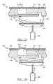
- the displacement device 140can include an actuator coupled to a pair of platens, and the bladder can be sandwiched between the pair of platens such that actuation of the actuator compresses the bladder to displace fluid into the fluid channel 112 .
- Each platencan be substantially rigid, such as defining a stamped steel plate or a molded plastic platter with strengthening ribs.
- a first platen 141 of the paircan be fixed or otherwise rigidly coupled to the substrate 110 , a touchscreen, a housing of the device, or an other component within the device, and the actuator can move the second platen 142 (e.g., in translation) toward the first platen to displace fluid out of the bladder, thereby increasing pressure within the fluid system and transitioning the deformable region 122 from the retracted setting into the expanded setting.
- both platens (and additionally platens) in the setcan be movable relative to each other and/or to the substrate 110 to similarly deform the bladder.
- the bladdercan be glued, clamped, adhered, or otherwise mechanically fastened to each of the platens, as shown in FIG. 3A .
- the displacement device 140can further retract the platens (i.e., move the platens away from each other) to decrease pressure within the fluid system and/or to create draw a vacuum within the bladder, thereby actively drawing fluid out of the fluid channel 112 and back into the reservoir 130 to retract the deformable region 122 .
- the bladdercan be sandwiched between but detached from one or more platens in the set of platens, and elasticity of the bladder (and/or the deformable region 122 ) can cause the bladder to return to original shape, thereby drawing fluid back out of the fluid channel 112 and transitioning the deformable region 122 back into the retracted setting when the displacement device 140 releases the platens.
- the displacement device 140can include an actuator coupled to a single platen, and the bladder can be sandwiched between the platen and an interior surface of the substrate no opposite the tactile layer 120 .
- actuation of the actuatorcan compress the bladder to displace fluid into the fluid channel 112 (e.g., through the via in the substrate no), thereby transitioning the deformable region 122 from the retracted setting into the expanded setting.
- the bladdercan be glued, adhered, fastened, or otherwise attached to the interior surface of the substrate no and/or to the platen. The portion of the substrate no can thus function as the second platen 142 described above and cooperate with the first platen to compress, stretch, or otherwise manipulate the bladder when the displacement device 140 is actuated.
- the bladdercan be arranged between a platen and any other surface within the electronic device incorporating the dynamic tactile interface.
- the bladdercan be arranged between a single platen and a planar surface of a battery, a back surface of a touchscreen, or an internal surface of a housing of the device, and the displacement device 140 can compress the bladder and any of the foregoing surfaces to displace fluid out of and/or into the bladder.
- the platenscan define two opposing linkages in a four-bar linkage such that the opposing surfaces of the platen move parallel one another as the reservoir 130 is compressed and/or expanded.
- the platenscan be hinged to one another such that the reservoir 130 can be pinched or stretched between the pivoting platens.
- at least one platencan be pivotably coupled to an alternative component, such as to a housing that contains a touchscreen and the dynamic tactile interface, to a PCB within the housing, to the substrate no, or to the touchscreen.
- a first platen 141can also be coupled to a flexure that accommodates linear and/or rotary motion of the first platen 141 relative a second platen 142 to enable the platens to move toward and away from each other to thus compress and expand the reservoir 130 , respectively.
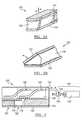
- a first platen 141can move within a guide channel 144 that constrains the platen in fewer than six° of freedom, wherein motion of the first platen 141 along the guide channel 144 brings the first platen 141 and a second platen 142 closer together or further apart.
- the guide channel 144can be a straight guide channel 144 in which the first platen 141 moves linearly within the guide channel.
- the guide channel 144can be curved, sinusoidal, curvilinear, or otherwise not wholly linear. For example, as shown in FIG.
- the guide channel 144can be sinusoidal with a first asymptote at one end of the guide channel 144 that corresponds with the retracted setting and with a second asymptote at the opposite end of the guide channel 144 that corresponds with the expanded setting.
- the asymptotic ends of the guide channel 144can function as steady state holding positions for the first platen 141 , thus requiring minimal holding power and therefore minimal power consumption from the displacement device 140 in a steady-state retracted or expanded setting.
- the displacement device 140includes a cam block 148 defining a guide channel, a drive screw that engages the cam, and a rotary actuator 143 (e.g., a motor) configured to drive the cam block 148 along the drive screw by rotating the drive screw.
- a rotary actuator 143e.g., a motor
- the first platen 141is pivotably mounted to the second platen 142 (or to another component within the dynamic tactile interface and/or electronic device coupled to the second platen 142 ) and includes a tab 147 that engages the guide channel.
- the cam block 148moves linearly along a first linear direction, and the first platen 141 pivots about its hinge toward the second platen 142 as the tab 147 follows the guide channel.
- the platenscompress the reservoir 130 , drive fluid out of the reservoir 130 and into the fluid channel 112 , and thus transition the deformable region 122 from the retracted setting into the expanded setting.
- the cam block 148moves linearly in a second linear direction opposite the first linear direction, the tab 147 moves vertically upward to follow the guide channel, and the first platen 141 is driven away from the second platen 142 to stretch the reservoir 130 and thus transition the deformable region 122 from the expanded setting to the retracted setting.
- the displacement device 140can further incorporate a second driven or passive cam block 148 across the first platen 141 opposite the cam block 148 , wherein the second cam block 148 engages a second tab 147 on the first platen 141 such that the first platen 141 can be driven toward the second platen 142 in linear translation rather than in rotation (i.e. by pivoting about a hinge).
- the drive screwcan be a single lead acme screw, a double lead acme screw, or any other suitable type of screw.
- the drive screwcan be directly or indirectly coupled to the actuator on one end, such as with a flex coupling or a universal joint.
- the drive screwcan be further supported on an opposite end by a bushing or bearing, such as mounted to the substrate 110 opposite the tactile layer 120 or mounted to the housing of the electronic device that includes the dynamic tactile interface.
- the cam block 148can include a circumferential or partial nut that engages one or more threads of the drive screw, or the cam block 148 can include a tab 147 that engages a trough in the lead screw thread to drive the cam block 148 fore and aft as the drive screw rotates.
- the actuatorcan be rigidly mounted to the substrate no opposite the tactile layer 120 or mounted to the housing of the electronic device that includes the dynamic tactile interface.
- the actuatorcan be bonded to the back of the substrate no with an epoxy-based adhesive.
- the actuatorcan be flexibly mounted, such as retained by a soft (e.g., rubber) motor mount that accommodates blemishes within the drive train as the lead screw 145 rotates.
- the lead screw 145 , cam block 148 , and actuatorcan interface and can be mounted in any other suitable way within the dynamic tactile interface and/or within the electronic device to manipulate fluid into and/or out of the fluid channel 112 .
- the actuatorcan be an electric motor selected to meet a requisite torque required to compress and/or stretch the reservoir 130 , to meet a requisite transition time between the retracted and expanded settings for one or more deformable regions, for a peak or constant supplied voltage, current, or power limit from the electronic device, to limit stress on the reservoir 130 or the substrate no, etc.
- the actuatorcan be selected to enable transition between the retracted and expanded setting at the deformable region 122 within two seconds.
- the actuatorcan be selected to enable displacement of 1 mL per second, to match a 3V nominal power supply within the electronic device, for a maximum stall current of 100 mA, or for a peak torque of 1 mNm.
- the actuatorcan also be an electric gearhead motor with a gear ratio matched to the pitch of the drive screw to meet one or more of the foregoing criteria.
- the drive screw 145can be a lead screw with a 0.025′′ pitch and the motor can include a planetary gearhead that converts a nominal motor speed of 20,000 rpm to 400 rpm, thus displacing the cam block 148 . 5 ′′ every three seconds.
- the actuatorcan be a shape memory alloy (e.g., nitinol) motor, a piezoelectric motor, or any other suitable type or size of actuator with or without a geared output.
- the guide channel 146can be a linear guide channel.
- the guide channel 146can be curvilinear or sinusoidal.
- the guide channel 146can include a half-sinusoid section that terminates at each end with a linear segment, as shown in FIG. 4 .
- a first linear segment of the guidecan correspond to the retracted setting
- a second linear segment opposite the half-sinusoidcan correspond to the expanded setting
- the first and second linear segmentsfully support the tab 147 or cam follower coupled to the first platen 141 such that the actuator does not draw power to hold the deformable region 122 in either the retracted setting or the expanded setting.
- the actuatorcan thus draw power only drive tab 147 across the half-sinusoid section.
- the displacement device 140includes an electric gearhead motor with an eccentric drive pin 241 configured to engage an elongated slot 242 in a tab 147 extending from a first platen 141 pivotably mounted to the second platen 142 (or to another component within the dynamic tactile interface and/or electronic device), as shown in FIGS. 6A and 6B .
- a first arcuate position of the eccentric drive pin 241can correspond to the retracted setting
- a second arcuate position of the eccentric drive pin 241can correspond to the retracted setting.
- the first and second arcuate positionscan be offset by 180°, and the eccentric drive pin 241 translate from a first linear position to a second linear position and back to the first linear position within the elongated slot 242 as the output shaft 146 of the motor rotates through a 180° arc, as shown in FIG. 6A .
- the eccentric drive pin 241first moves toward the innermost end of the elongated slot 242 in the tab, thus decreasing the angle between the first and second platens.
- the motorapplies a peak torque to the tab, and the eccentric drive pin 241 begins to move back toward the outermost end of the elongated slot 242 .
- the output shaft 146 of the motorcontinues to rotate to the second arcuate position 180° from the first arcuate position at which point the motor stops, as shown in FIG. 6B .
- the length of the elongated slot 242 and the position of the centerline of the motor relative to the slotcan be such that the eccentric drive pin 241 reaches a linear displacement limit within the elongated slot 242 at the outmost end of the elongated slot 242 at the first position and the second position that is 180° offset from the first position.
- the elongated stopcan thus brake the motor at the limits of the expanded and retracted settings.
- a motor controller 148(and/or processor) electrically coupled to the motor can further measure current draw of the motor and determine that the motor has reached an endstop when the actual current draw exceeds a threshold current draw, and the motor controller 148 can cut power to the motor accordingly.
- the motor or motor output shaft 146can be coupled to an encoder, limit switch, potentiometer, or other sensor that feeds position data to the motor controller 148 (and/or processor) to identify travel limits of the motor output shaft 146 and/or offset shaft.
- the length of the elongated slot 242 and the position of the centerline of the motor relative to the slotcan also be such that the eccentric drive pin 241 is limited to less than 180° of rotation.
- the length of the elongated slot 242 and the position of the centerline of the motor relative to the slotcan define maximum travel limits of the eccentric drive pin 241 such that a force applied to the first platen 141 by the reservoir 130 translates into substantially no torque applied to the eccentric drive pin 241 by the tab 147 or the elongated slot 242 in either the expanded or retracted settings.
- This configurationcan enable the displacement device 140 to maintain both the expanded and retracted settings substantially without additional power draw from the motor.
- the gearhead motorcan be configured to move from one extreme travel position to an opposite extreme travel position (e.g., 180° of rotation or less) within a desired setting transition time.
- the gearhead motorcan complete a full rotation in six seconds and slightly less than 180° of rotation slightly less than three seconds.
- the motorcan include a gearhead that converts a nominal motor speed of ⁇ 20,000 rpm to ⁇ 360 rpm with a 56:1 planetary gear set.
- the displacement device 140includes a set of linkages that couple to the first and second platen to form a bar linkage such that the first platen 141 moves parallel to the second platen 142 as the displacement device 140 transitions the deformable region 122 between settings.
- the displacement device 140further includes a rotary actuator 143 , a lever arm, and a lead screw coupled to the lever arm via a nut 144 , and the lead screw and the lever arm can to translate rotary motion of the actuator into translation of the first platen 141 relative the second platen 142 , as shown in FIG. 7 .
- the displacement device 140includes a carriage with offset guide channels 144 , each guide channel 144 configured to engage a tab 147 extending from the first platen 141 .
- the displacement device 140further includes a motor, lead screw, lever arm, and/or nut 144 configured to displace the first platen 141 along the guide channel 144 to reduce or increase the distance between the parallel faces of the first and second platens, thus compressing and stretching the reservoir 130 , respectively, as shown in FIG. 4 .
- the guide channels 144can define linear guide channels 144 .
- the guide channels 144can be curvilinear or sinusoidal in section, such as described above.
- the guide channels 144can also be identical and offset to enable broad faces of the first and second platens to remain parallel between settings, or the guide channels 144 can be dissimilar such that broad faces of the first and second platens translate linearly and arcuately between settings.
- the actuatorcan be an electric gearhead motor or any other suitable type of motor
- the drive screwcan be an acme lead screw or any other suitable type of lead screw.
- the motorcan be directly or indirectly coupled to the drive screw (e.g., via a flex coupling or a universal joint), and the drive screw can directly engage the carriage or the first platen 141 or engage the first platen 141 via a lever arm, nut 144 , or other suitable component.
- the displacement device 140 of the foregoing implementationscan include any other component and define any other configuration to manipulate the reservoir 130 to thereby transition the deformable region 122 between retracted and expanded settings.
- the dynamic tactile interfacecan also include any number of similar or dissimilar displacement devices and/or reservoirs configured to transition a multiple fluidly coupled or fluidly discrete deformable regions between expanded and retracted settings.
- the reservoir 130includes a bellows 245 configured to hold fluid, as shown in FIGS. 8A and 8B .
- the bellows 245can be fluidly coupled to the fluid channel 112 via a junction block 343 , barb, and/or via, etc., and the combination of any of the foregoing components with the fluid channel 112 , the fluid conduit 114 , the bellows 245 , and the deformable region 122 can define a sealed and enclosed fluid system.
- the bellows 245includes a metallic structure, such as a stainless steel, electron-beam welded structure.
- the bellows 245can be a plastic or polymer structure, such as a blow-molded PVC structure.
- the bellows 245can be circular in cross section, rectangular in cross section, or of any other suitable cross section.
- the bellows 245can also be elongated, squat, or of any other suitable form or geometry.
- the bellows 245can be sized for a requisite total fluid displacement between retracted and expanded settings.
- the displacement device 140can include a linear actuator that advances and retracts the bellows 245 to expand and retract the deformable region 122 , respectively.
- the linear actuator of the displacement device 140can include a rotary actuator 143 coupled to any one or more of a bellcrank, a cam, a lead screw paired with a nut 144 , or any other suitable device configured to translate rotary motion into linear motion, as shown in FIG. 8A .
- the linear actuatorcan be a linear motor, a solenoid, or any other suitable type of actuator.
- the bellows 245can be captured on one end, and the linear actuator can apply a compressive and/or tensile force to the opposite end of the bellows 245 to manipulate the internal volume of the bellows 245 .
- the displacement device 140can also include a carriage that maintains alignment of the bellows 245 throughout its travel.
- the carriage, bellows 245 , and/or linear actuatore.g., rotary actuator 143 and mechanism
- the carriage, bellows 245 , and/or linear actuatorcan further include a mechanical stop at each end of a desired travel limit such that a linear actuator controller (and/or processer) can monitor current draw of the linear actuator to determine the position thereof, as described above.
- the bellows 245can be a squat round bellows 245 coupled to a rotary actuator 143 via a lead screw and bellcrank, wherein endstops arranged on the lead screw define travel limits of the displacement device 140 and bellows 245 .
- a first end of the bellows 245is fixed (e.g., rigidly coupled to the substrate no, such as through the touch sensor and/or the display 150 ), and a second end of the bellows 245 opposite the first end runs in a track parallel to the axis of the bellows 245 .
- a lead screwis arranged parallel and offset from the track, is supported near the first end of the bellow, and runs through a nut 144 coupled to the second end of the bellows 245 .
- the actuator 143spins the lead screw to drive the second end of the bellows 245 toward and away from the first end to expanded and retract the deformable region 122 , respectively.
- the reservoir 130 that includes a bellows 245can be implemented in any other way and can be manipulated between settings in any other way and by any other suitable displacement device to transition the deformable region 122 between settings.
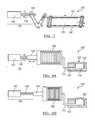
- the reservoir 130includes a tube defining a first end fluidly coupled to the fluid channel 112 and constrained relative to the substrate no
- the displacement device 140includes a rotary actuator 143 coupled to the tube 341 remote from the first end and configured to transition the deformable region 122 from the retracted setting to the expanded setting by winding the tube 341 to displace a portion of the volume of fluid 170 within the tube 341 into the fluid channel 112 .
- the reservoir 130 of the dynamic tactile interfaceincludes: a tube 341 including a first end and a second end opposite the first end, the first end constrained and defining an outlet; a cap 349 coupled to the second end of the tube 341 .
- the volume of fluid 170is arranged within the tube 341 .
- the displacement device 140includes: a rotary actuator 143 including an output shaft 146 coupled to the second end of the tube 341 and configured to wind the tube 341 to displace a portion of the volume of fluid 170 from the tube 341 ; and a balance spring 247 coupled to the second end of the tube 341 and configured to balance a torque applied by the tube 341 to the output shaft 146 of the rotary actuator 143 .
- the tube 341can be fluidly coupled at the first end to the fluid channel 112 via a barb, junction block 343 , or secondary tube, etc. to define a sealed and enclosed fluid system with the fluid channel 112 , the fluid conduit 114 , and the deformable region 122 , as shown in FIGS. 9A and 9B .
- the actuator 143 of the displacement device 140can thus twist the tube 341 , thereby constricting the interior wall of the tube 341 , reducing the internal volume of the tube 341 , and displacing fluid out of the tube 341 and into the fluid channel 112 to transition the deformable region 122 into the expanded setting.
- the tube 341can therefore be of an elastic or elastomeric material, such as silicone rubber, latex, or PVC, such that the tube 341 can be reliably and repeatedly twisted without substantial plastic (i.e. permanent) deformation.
- the tube 341defines a smooth tube of a constant circular cross section and wall thickness along its length.
- the tube 341is internally and/or externally ribbed or corrugated, which aids the tube 341 in returning to an initial uncoiled (i.e., untwisted) state.
- the tube 341includes an elastic tubular core inset within a metallic coil spring.
- the tube 341includes a metallic coil spring encased in an elastomer to enclose an internal inside the metallic coil spring.
- the tube 341can include an internal or external stent configured that winds with the tube 341 and is configured to return the tube 341 to an unwound state once a torque is released from the tube 341 .
- the tube 341can similarly include linear and/or coiled shape memory elements embedded within a pliable tubular core of one or more elastomeric materials.
- the tube 341can be a silicone rubber tube with a shape-memory alloy (SMA) wire coil shallowly embedded in the external surface of the tube 341 .
- SMAshape-memory alloy
- the tube 341can also define a varying cross-section and/or geometry along its length to control location of an initial fold (i.e., coil) in the tube 341 as the actuator 143 begins to wind the tube 341 from a fully-uncoiled position.
- the cross-section and/or geometry of the tube 341can further control propagation of folds along the tube 341 as the actuator 143 further winds the tube 341 .
- the cross-section and/or geometry of the tube 341can initiate a first fold at the second end of the tube 341 with each subsequent fold propagating sequentially and adjacent a previous fold as the tube 341 is wound, thereby displacing fluid fully from the second end of the tube 341 to the first end of the tube 341 and into the fluid channel 112 .
- Such cross-section and/or geometrycan substantially prevent capture of fluid between two folds in the tube 341 , which may otherwise limit the maximum displacement capacity of the tube 341 and/or cause the tube 341 to rupture from increased fluid pressure between two folds.
- the tube 341defines a circular cross-section along its length with a flat section of a second width on the exterior of the tube 341 at its second end.
- the flat sectiontapers down to a first width less than the second width proximal the first end of the tube 341 .
- the maximum hoop stress that the tube 341 can withstand before bucklingcan be less at the second end than at the first end such that the tube 341 first buckles—to yield a first fold—at the second end and continues to buckle along sequential sections of the tube 341 .
- the tube 341can define additional tapered planar sections along its exterior (and/or interior).
- the tube 341can define an octagonal external cross-section at the second end, which transitions into a circular external cross-section at the first end.
- the tube 341defines a trough or U-shaped cross-section at the second end, which transitions into a square or circular cross-section toward the first end of the tube 341 .
- the troughcan create a weakest region in the tube 341 (e.g., a linear section of the tube 341 capable of a maximum hoop stress less than any other linear section of the tube 341 ) proximal at the second end such that the second end of the tube 341 is first to buckle or coil as the actuator 143 winds the tube 341 from a fully-unwound state.
- the tube 341defines a circular cross-section that tapers from a first external diameter at the first end to a second external diameter less than the first external diameter at the second end.
- the tube 341can define a constant wall thickness along its length.
- the wall thickness of the tube 341can taper from a first thickness proximal the first end to a second thickness less than the first thickness proximal the second end.
- the tube 341can thus be ‘weakest’ at the second end can capable of withstanding a maximum hoop stress before buckling that increases along the length of the tube 341 from the second end toward the first end. This configuration can thus yield preferential coiling of the tube 341 starting at the second end of the tube 341 and moving linearly along the tube 341 toward the first end as the actuator 143 winds the tube 341 .
- the internal diameter of the tube 341can taper from a first diameter at the first end to a second diameter less than the first diameter at the second end.
- the internal diameter of the tube 341can taper from a first diameter at the first end to a second diameter greater than the first diameter at the second end.
- the tube 341can displace a volume of fluid 170 per coil or per linear section of the tube 341 that is greater at the second end than at the first end of the tube 341 .
- the actuator 143can rotate (at substantially constant speed) to first coil the second end of the tube 341 to quickly inflate the deformable region 122 from the retracted setting and then progressively coil subsequent sections of the tube 341 toward the first end to achieve a specific volume displacement from the tube 341 with smaller and smaller volumes of fluid displaced as additional sections of the tube 341 are coiled.
- the tube 341is pinched proximal the second end.
- the reservoir 130can include a crimp, a clamp, or a band that constricts the tube 341 locally proximal the second end to cause the tube 341 to wind first at the second end.
- the tube 341can be formed or reformed with a first coil proximal the second end.
- the tube 341 and/or the reservoir 130can include any other feature or be of any other geometry to control a site of first coiling on the tube 341 when the displacement device 140 first winds to the tube 341 to transition the deformable region 122 from the retracted setting to the expanded setting.
- the tube 341can also be of a coiled geometry, such as a densely-wrapped coil or a loosely-wrapped coil. Furthermore, the tube 341 can also be housed in a substantially rigid sheath or coil that prevents the tube 341 from folding over itself when twisted and/or released. For example, the tube 341 can be arranged within an elongated housing of internal cross-section that accommodates enough offset from the tube 341 to allow the tube 341 to coil once when twisted but that prevents the coiled section of the tube 341 from coiling back on themselves. For example, the internal width and/or diameter of the housing can be approximately twice the external diameter of the tube 341 .
- the reservoir 130can also include a cap 349 that closes the second end of the tube 341 and functions as a junction between the tube 341 and the rotary actuator 143 .
- the cap 349can include a crimp fitting that locks into the second end of the tube 341
- the cap 349can further include a keyed or splined bore that slips over an output shaft 146 of the actuator 143 to transfer torque from the actuator 143 into the tube 341 .
- the tube 341can be of any other form, geometry, cross section, and/or material.
- the displacement device 140includes a rotary actuator 143 configured to twists the tube 341 , thereby displacing fluid out of the tube 341 and into the fluid channel 112 .
- the actuator 143can include a gearhead motor with output shaft 146 coupled to the tube 341 , such as via the cap. Actuation of the gearhead motor in a first arcuate direction can thus twist the tube 341 , causing it to coil and reducing its internal volume. Similarly, actuation of the gearhead motor in a second—opposite—arcuate direction can unwind the tube 341 , enabling fluid to flow back into the tube 341 .
- the actuator 143can be an electric motor, an electric gearhead motor, a rotary solenoid, a stack of doped latex tubes, or any other suitable actuator.
- a hinge, track, or other mechanism within the computing devicecan be coupled to the second end of the tube 341 .
- a force or torque appliede.g., manually
- the second end of the tube 341can also be coupled to a power transmission component that translates a manual input directly into the tube 341 to manipulate fluid into and/or out of the tube.
- the second end of the tubecan be coupled to any other type of manual, electromechanical, pneumatic, or other actuator or power transmission component.
- the actuator 143is mounted at a fixed distance from the first end of the tube 341 such that the length of the tube 341 remains substantially constant as it is coiled and uncoiled.
- the actuator 143can be configured to move along a linear slide parallel to an axis of the tube 341 to accommodate a change in length of the tube 341 as the tube 341 is coiled and uncoiled, thereby limiting axial tension in the tube 341 , as shown in FIGS. 9A and 9B .
- the actuator 143can be coupled to a spring 246 (e.g., a coil spring) that tensions the tube 341 via the actuator 143 to retract the actuator 143 once power is cut from the actuator 143 or when the actuator 143 is reversed to uncoil the tube 341 from a twisted state.
- the spring 246can include a coil spring coupled to the actuator 143 at a far side of the actuator 143 opposite the second end of the tube 341 and coupled to the substrate 110 opposite the first end of the tube 341 .
- the spring 246can elongate, increasing tension on the tube 341 to return the tube 341 to the uncoiled state.
- the spring 246can include a coil spring arranged over the tube 341 with its axis coincident with the axis of the tube 341 , the coil spring acting directly on the rotary actuator 143 .
- the spring 246can compress, increasing a restorative force applied to the actuator 143 to tension the tube 341 .
- a springcan be directly coupled to the second end of the tube 341 to tension the tube 341 as it is wound, and the cap 349 and include an internal or external spline.
- the actuator 143can thus be coupled to the cap 349 via a splined shaft that engages the spline of the cap 349 such that the cap 349 can translate relative to the actuator 143 as the tube 341 is wound.
- the spring 246can be any other suitable type of spring arranged in any other way to tension the tube 341 to return the tube 341 to an uncoiled state when the actuator 143 releases torque on the tube 341 and/or reverse in direction to uncoil the tube 341 .
- the displacement device 140can also include a balance spring 247 configured to balance a torque applied by the tube 341 to an output shaft 146 of the rotary actuator 143 .
- the balance spring 247can apply a moment to the output shaft 146 of the actuator 143 that is substantially equal and opposite to a moment applied to the output shaft 146 of the actuator 143 for at least one uncoiled positions of the tube 341 .
- the balance spring 247can fully balance a torque applied to the output shaft 146 of the actuator 143 by the tube 341 .
- the balance spring 247can reduce (e.g., halve) a maximum torque that the actuator 143 must output to wind the tube 341 throughout the possible coiled and uncoiled positions of the tube 341 .
- the actuator 143includes an electric motor with a common output shaft 146 passing through end of the motor.
- the tube 341is coupled to output shaft 146 at a first side of the motor
- the balance spring 247is coupled to the output shaft 146 at the opposite end of the motor and fixed at a far end remote from the first end of the tube 341 with the axis of the balance spring 247 substantially coincident with the axis of the tube 341 .
- the balance spring 247can be preloaded to apply a torque to the output shaft 146 of the actuator 143 such that the balance spring 247 cancels a torque applied to the actuator by the tube 341 when the tube 341 is half-coiled.
- the balance spring 247can include a second tube 342 , such as substantially similar to the (first) tube—which contains fluid, though the second tube 342 can be devoid of fluid.
- the balance spring 247can include a metallic coil spring, though the balance spring 247 can include any other suitable type of spring of any other suitable material.
- the balance spring 247can be directly coupled to the second end of the tube 341 .
- the cap 349 of the tube 341can define a junction between the tube 341 and the balance spring 247 .
- the cap 349defines a toothed gear
- the output shaft 146 of the actuator 143is coupled to a pinion that engages the toothed gear to wind the tube 341 and the balance spring 247 , as shown in FIG. 13 .
- the actuator 143can be coupled to the cap 349 of the tube 341 via a shaft that passes through the balance spring 247 , as shown in FIG. 12 .
- the balance spring 247includes a second tube 342 substantially identical to the (first) tube but, unlike the tube 341 , devoid of fluid.
- the first end of the tube 341is coupled to a junction block 343 via a barb in fluid communication with the fluid channel 112
- the second tube 342is preloaded and similarly coupled to the junction block 343 at a first end.
- the output shaft 146 of the actuator 143is further coupled directly to the cap 349 at the second end of the tube 341 , and the cap 349 (or the output shaft 146 ) includes (or is coupled to) a first pinion that engages a second pinion coupled to a second end of the second tube 342 adjacent the second end of the (first) tube.
- the first and second pinionscan include an identical number of gears to yield a gear ratio of 1:1.
- the second tube 342can be equally unwound in an opposite direction to balance a torque applied to the actuator 143 by the (first) tube.
- the balance spring 247can alternatively include a coil spring (shown in FIG. 13 ), a torsion bar, or other suitable component to mechanically store energy to balance a moment applied to the actuator 143 by the tube 341 , and the balance spring 247 can be geared or otherwise coupled to the tube 341 in any other way and at any other ratio control transmission of torque from the balance spring 247 into the tube 341 and/or into the rotary actuator 143 .
- the displacement device 140can additionally or alternatively include a ratchet and pawl mechanism configured to lock a position of the second end of the tube 341 relative to the first end of the tube 341 .
- the ratchet 346 and pawl mechanismcan latch to hold the position of the second end of the tube 341 such that the power to the actuator 143 can be cut without unwinding the tube 341 .
- the pawl 345is coupled to the actuator housing (or to an actuator mount) via a clutch 347
- the ratchet 346is coupled to the output shaft 146 of the actuator.
- the clutch 347moves the pawl 345 into a lock position.
- the pawl 345skips over the rotating ratchet.
- energy stored in the coiled tubeis released as a torque applied to the output shaft 146 of the actuator 143 in a second direction opposite the first direction.
- the pawl 345engages the ratchet 346 and locks the arcuate position of the ratchet 346 and thus the coiled position of the tube 341 .
- Power to the actuator 143can thus cease as the deformable region 122 is held in the expanded setting.
- the output shaft 146 of the actuator 143can begin to rotate in the opposite direction, which causes the clutch 347 to release the pawl 345 from the ratchet 346 .
- the tube 341can thus unwind passively, or the actuator 143 can actively return the tube 341 to an unwound state.
- the ratchet 346 and the pawl 345can be arranged in any other configuration and can function in any other way to latch an arcuate position of the output shaft 146 of the actuator 143 and therefore a coiled position of the tube 341 .
- the displacement device 140includes a static endplate 542 and a friction plate 541 that cooperate to lock the arcuate position of the output shaft 146 of the actuator 143 and therefore the wound position of the tube 341 in the expanded setting, as shown in FIGS. 15A and 15B .
- the friction plate 541can latch to the endplate 542 to hold the position of the second end of the tube 341 such that the power to the actuator 143 can be cut without unwinding the tube 341 , such as to extend a battery life of the electronic device incorporating the dynamic tactile interface.
- the friction plate 541can be mounting on the output shaft 146 of the actuator 143 with a threaded shaft 145 extending out away from the actuator 143 toward the second end of the tube 341 .
- the endplate 542can be coupled to the substrate no (e.g., via the touchscreen or a chassis within the electronic device) and arranged between the friction plate 541 and the tube 341 with the threaded shaft 145 engaging a threaded bore (or nut 144 ) passing through the endplate 542 .
- the friction plate 541is offset from the endplate 542 , as shown in FIG. 15A .
- the threaded shaft 145rotates in the threaded bore, advancing the friction plate 541 toward the endplate 542 according to a pitch of the threaded shaft 145 and threaded bore.
- the friction plate 541makes contact with the endplate 542 , the mating surfaces bind, locking the arcuate position of the output shaft 146 .
- the friction plate 541 and the endplate 542thus latch the coiled position of the tube 341 to maintain the deformable region 122 in the expanded setting without sourcing additional power to hold the rotary actuator 143 , as shown in FIG. 15B .
- the actuator 143applies a torque to the friction plate 541 to release the friction plate 541 pawl from the endplate 542 .
- the actuator 143then continues to rotate in the second direction to return the tube 341 to an unwound state.
- the initial distance between the friction plate 541 and the endplate 542 in the fully-unwound position of the tube 341can define a preset number of rotations of the output shaft 146 before the friction plate 541 locks to the endplate 542 —and therefore a preset or target number of coils or windings in the tube 341 in the expanded setting.
- the position of the endplate 542 and/or the position of the friction plate 541can be set and adjusted manually.
- a set screwcan be accessed with a wrench through a external housing or body of the electronic device incorporating the dynamic tactile interface, and the set screw can be rotated to linearly translate the endplate 542 toward or away from the friction plate 541 or to adjust the arcuate position of the friction plate 541 on the threaded shaft 145 .
- this adjustmentcan be made during initial assembly of the electronic device or after disassembly of the electronic device to tune the height, size, shape, and/or firmness, etc.
- the dynamic tactile interfacecan include a second endplate 542 arranged adjacent the friction plate 541 opposite the endplate 542 , which can similarly define an arcuate position of the second end of the tube 341 in the retracted setting as the friction plate 541 is driven away from the endplate 542 and into the second endplate 542 .
- the friction plate 541 and the endplate 542 , etc.can be arranged in any other configuration and can function in any other way to latch an arcuate position of the output shaft 146 of the actuator 143 and therefore a coiled position of the tube 341 to maintain the deformable region 122 in the expanded setting.
- the dynamic tactile interfacecan includes a motor controller 148 (and/or processor) configured to monitor current draw of the actuator 143 and to correlate the current draw with a coiled position of the tube 341 .
- the motor controller 148can correlate a current draw from the actuator 143 with a volume of fluid 170 displaced from the tube 341 and control an arcuate position of the output shaft 146 of the actuator 143 accordingly.
- the motor controller 148 (and/or processor)can implement a lookup table to associate a particular current draw or range of current draws at the actuator 143 with a particular volume of fluid 170 displacement from the tube 341 .
- the motor controller 148can correlate a rapid increase in current draw at the actuator 143 with engagement of the friction plate 541 with the endplate 542 and cut power to the actuator 143 accordingly.
- the motor controller 148can implement closed loop feedback control to move the output shaft 146 of the actuator 143 to an arcuate position associated with a minimal current draw, which can correspond to a fully-unwound state of the tube 341 —and the retracted position at the deformable region 122 .
- the motor controller 148can interface with a pressure sensor fluidly coupled to the fluid channel to monitor fluid pressure with the fluid channel 112 , to estimate the volume of fluid 170 displacement from the reservoir 130 accordingly, and the control the position of the actuator 143 based on the estimate fluid displacement.
- the motor controller 148(and/or the processor) can function in any other way to control the actuator 143 to achieve a target volume displacement from the tube 341 and/or target fluid pressure within the fluid channel 112 .
- the displacement device 140can incorporate any combination of the foregoing components or subsystems, such a pawl 345 and ratchet mechanism with a balance spring 247 or a friction plate 541 and endplate 542 with a rotary actuator 143 that translates linearly along linear track 248 .
- the reservoir 130 and the displacement device 140can be of any other form and/or geometry and include any other component or subsystem to displace fluid out of the reservoir 130 and into the fluid channel 112 to transition the deformable region 122 from the retracted setting to the expanded setting.
- the reservoir 130includes a linear tube coupled at a first end to an inlet of the fluid channel 112 and coupled at a second end to an outlet of the fluid channel 112 , wherein the fluid conduit 114 is arranged between the inlet and the outlet of the fluid channel 112 .
- a valvee.g., a check valve, a one-way valve, a bi-state valve
- the valvescan be fixed to enable fluid to fluid into the second end and out of the first end of the tube 341 such that the output shaft 146 of the actuator 143 can oscillate (e.g., clockwise 360° and then counterclockwise 360° and back) to induce flow through the tube 341 .
- the first end of the tube 341can be fixed to the substrate 110 , such as via a junction block 343 , and the second end of the tube 341 can be coupled to a geared barb such that the actuator 143 can apply a torque to the barb to twist the tube 341 .
- the tube 341 , valves, and rotary actuator 143can thus cooperate to produce continuous circulating flow.
- the displacement devicecan include a bi- or tri-state valve that opens one end of the tube 341 to a second reservoir or to ambient air such that the tube 341 can draw fluid or air from the second reservoir or ambient, respectively, and into the fluid channel to transition the deformable region 122 into the expanded setting.
- Selective actuation of the valvescan also enable the displacement device to pump fluid or air out of the fluid channel and into the second reservoir or exhausted to ambient to transition the deformable region back into the retracted setting.
- valvescan be transiently set in a first state to enable flow only out of the tube 341 .
- the tube 341can include any of the foregoing features described above to yield preferential initial buckling and coiling of the tube 341 near its longitudinal center such that, when the actuator 143 first applies a torque to the tube 341 , the tube 341 coils at its longitudinal center with additional coils subsequently forming on each side of the longitudinal center to drive fluid out of each end of the tube 341 .
- the deformable region 122is fully expanded, power to the actuator 143 can be cut, as the valves prevent fluid from draining back into the tube 341 .
- the actuator 143can also be actively driven in reverse to control uncoiling of the tube 341 .
- the state of the valvescan be switched to allow fluid only to drain back into the tube 341 , and the actuator 143 can also be actively driven in reverse to uncoil the tube 341 , or the tube 341 can uncoil passively to draw fluid back from the fluid channel 112 . Therefore, in this configuration, fluid can be pumped from the tube 341 into the multiple inlets at the substrate 110 , which can yield more uniform flow of fluid through the fluid channel 112 .
- this configurationcan further yield more uniform transition of the deformable region(s) 122 as more uniform fluid flow, higher flow rates, and/or higher fluid pressures may be enabled by the two fluid inlets over the single fluid inlet described above.
- a first valvecan be arranged between ambient air and the tube, and a second valve can be arranged between the tube and the fluid channel.
- the first valvecan be opened and the second valve closed to enable air to fill the tube.
- the states of the valvescan then switch, and the actuator can wind the tube to displace air into the fluid channel. (The actuator can also begin to wind the tube before the valve states switch to pre-pressurize the tube.)
- the second valveto switch to a closed state to hold air in the fluid channel.
- the first valvecan open and the actuator can actively or passively unwind the tube to allow additional air to fill the unwound tube.
- the first valvecan then close, the second valve then opened, and the tube further wound to displace additional air into the fluid channel.
- the actuatorcan unwind the tube with the first and second valves open to exhaust air back to ambient.
- the dynamic tactile interfacecan reverse the foregoing series of steps.
- the second end of the tube 341is open to ambient air, and the actuator 143 winds the tube 341 to pump air from outside the electronic device into the fluid channel 112 to transition the deformable region 122 between settings.
- the tube 341can seal air inside the fluid channel to maintain the deformable region 122 in the expanded setting, and the actuator 143 can release the tube, and the tube can unwind to release air from the fluid channel 112 , thereby releasing the deformable region 122 to transition back to the retracted setting.
- the valve(s)can be any other suitable type of valve, such as a standard electromechanical bi-state (i.e., open or closed) valve.
- the tube 341can support fluid flow through each of its first and second ends and can cooperate in any other way with the rotary actuator 143 , valve(s), etc. to displace fluid into and/or out of the fluid channel 112 to transition the deformable region 122 between settings.
- manipulation of the tube as described abovefunctions to both decrease an internal volume of the tube and to store potential energy in the wall(s) of the tube (or attached mechanical structure).
- fluidis displaced out of the tube and into the fluid channel to transition the deformable region into the expanded setting.
- the tubeunwinds itself once torque or tension on the tube is released, thereby returning to a larger-volume state (and drawing fluid back into the tube).
- the tubecan therefore be manipulated as described above by twisting the tube about the tube's axis.
- the actuatorcan stretch the tube along its axis (or perpendicular to its axis), the internal volume of the tube thereby decreasing and the tube storing potential energy from the displacement.
- energy stored in the walls of the tubecan move the tube back to its original length, thereby drawing fluid back into the tube.
- the tubecan be wound about an axis perpendicular to the axis of the tube.
- the tubecan be wound around a spool like a fire hose to displace fluid out of the tube, and the energy stored in the wall of the tube can cause the tube to unwind from the spool once torque or tension on the spool is released.
- the dynamic tactile interfacecan include any other actuator that manipulates the tube in any other way to change the internal volume of the tube and to store energy in the wall of the tube and/or a connected mechanical structure (e.g., a spring, etc.).
- the reservoir 130includes any of a fluid bladder, a tube 341 , a diaphragm, a bellows 245 , a static vessel, or any other suitable vessel or container configured to hold fluid.
- the reservoir 130is fluidly coupled to the fluid channel 112 via the displacement device 140 , which includes a peristaltic pump configured to displace fluid into and out of the reservoir 130 to transition the deformable region 122 between the expanded and retracted settings, respectively.
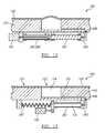
- the reservoir 130is partially defined by a portion of the substrate 110 opposite the tactile layer 120 .
- the portion of the substrate 110can include a recessed area or valley.
- a first open stage channel 442connects the portion of the substrate 110 to a first holding cavity 441 on the back surface of the substrate 110 proximal the portion of the substrate 110 .
- a second open stage channel 442further connects the first holding cavity 441 to a second holding cavity 441 , and a third open stage channel 442 connects the second holding cavity 441 to a third holding cavity 441 .
- the holding cavitiesare arranged equidistant from a common point, and the last (e.g., third) holding cavity 441 is fluidly coupled to the fluid channel 112 , such as with a fluid via 446 that passes through the substrate 110 to meet the fluid channel 112 , such as shown in FIG. 10A .
- An elastomer layer 445 bonded to the back surface of the substrate noencloses the portion of the substrate no to define the reservoir 130 , encloses the open stage channels 442 , and the encloses the holding cavities to create a fully-enclosed fluid system including the reservoir 130 , multiple stage channels 442 , multiple holding cavities, the fluid channel 112 , and the cavity adjacent the deformable region 122 .
- the displacement device 140further includes one tappet 443 retained over each holding cavity 441 , a displacement plate 447 , and a rotary actuator 143 .
- the displacement plate 447defines a channel in the form of a ring torus canted off-axis from an axis of rotation of the displacement plate 447 , such as shown in FIG. 1 a .
- the central diameter of the torusis sized such that the channel engages and retains each tappet 443 over a respective cavity.
- the actuator 143(e.g., a gearhead motor with a bevel drive output) drives the displacement plate 447 about its axis of rotation, wherein high and low points of the torus-shaped channel contact each tappet 443 in phase, thus causing the tappets 443 to periodically and serially depress and release the elastomer layer 445 over respective holding cavities.
- Serial depression and release of the elastomer over the holding cavitiescan thus cause fluid pressure to build in the stage channels 442 between holding cavities, and timed release of tappets 443 via the displacement plate 447 can cause fluid to flow through the stage channels 442 in a continuous direction (i.e. out of the reservoir 130 ) as the actuator drives the displacement plate 447 in a first direction of rotation.
- the displacement device 140can similarly change the direction of fluid flow through the system.
- This example implementation of the displacement device 140can include additional stages, such as a fourth stage with a fourth stage channel 442 that fluidly couples a fourth holding cavity 441 to the third holding cavity 441 , such as shown in FIG. 10A .
- each additional stagecan include a holding cavity 441 arranged at a common distance from a shared point.
- each additional stagecan be sealed within the enclosed fluid system by the elastomer layer 445 , and a tappet 443 can act on the corresponding holding cavity 441 through the elastomer layer 445 .
- the holding cavitiescan be hemispherical, such as with a spherical radius substantially equivalent to the sum of the spherical radius of a tappet 443 and the thickness of the elastomer layer 445 , such as shown in FIG. 10B .
- the holding cavitiescan be cylindrical, conical, or frustoconical in geometry, or the holding cavities can be of any other suitable geometry.
- the size and geometry of the tappets 443can be matched to the size and geometry of the holding cavities and/or the thickness of the elastomer layer 445 over the holding cavities.
- a tappet 443can be sized for substantially minimal clearance between the elastomer layer 445 and the corresponding holding cavity 441 such that fluid leakage past the holding cavity 441 is substantially minimized when the tappet 443 is fully depressed, such as in during a steady-state position (e.g., a fully-retracted setting, a fully-expanded setting).
- the tappets 443can also be of a substantially hard material.
- the tappets 443can be stainless steel or casehardened chromium-molybdenum steel ballbearings.
- the tappets 443can be cylindrical, conical, frustoconical, or any other suitable shape to match the geometry of the holding cavities.
- the displacement plate 447is inverted and fixed with two stage channels 442 fluidly coupled to an inlet and to an outlet through the displacement plate 447 .
- a second actuator plateis arranged over the displacement plate 447 , rotates around a center of the stationary displacement plate 447 , and retains tappets 443 (e.g., ball bearings) at a specific radius from the center such that the tappets 443 fall into tracks on the displacement plate 447 .
- tappets 443e.g., ball bearings
- a moving sealis formed which forces fluid into the inlet, around the channels, and out of the outlet of the displacement plate 447 .
- the displacement device 140can include any other component or feature of any other suitable material or geometry and can cooperate with the substrate 110 and/or reservoir in nay other way to transition the deformable region 122 between the retracted setting and expanded setting.
- the steady-state position of the displacement device 140 and/or actuatorcan yield a positive pressure (i.e., greater than atmospheric pressure) within the reservoir 130 , fluid channel, and cavity in and/or during a transition into the expanded setting and a negative pressure (i.e. vacuum, or less than atmospheric pressure) within the reservoir 130 , fluid channel, and cavity in and/or during a transition into the retracted setting.
- Positive pressure in the enclosed fluid system (relative to atmospheric pressure) in the expanded settingcan enable the deformable region 122 to rise above the peripheral region 121 to create a tactilely distinguishable feature on the tactile surface.
- negative pressure in the enclosed fluid system (relative to atmospheric pressure) in the retracted settingcan draw fluid out of the cavity to substantially ensure that the deformable region 122 transitions to a position that is substantially flush with the peripheral region 121 to effectively eliminate a feature tactilely distinguishable from the peripheral region 121 on the tactile surface.
- the displacement device 140can maintain a pressure of 15 psi above atmospheric pressure within the enclosed fluid system in the expanded setting, and the displacement device 140 can maintain a pressure of 5 psi below atmospheric pressure within the enclosed fluid system in the retracted setting.
- the dynamic tactile interfacecan function in any other way to transition the deformable region 122 between retracted and expanded settings.
- one variation of the dynamic tactile interfacefurther includes a sensor 160 coupled to the substrate no opposite the tactile layer 120 and configured to output a signal corresponding to an input on a tactile surface of the tactile layer 120 .
- a sensor 160functions to enable detection on an input on the tactile surface, such as at the peripheral region 121 and/or at the deformable region 122 by outputting a corresponding signal.
- a sensor 160can be a capacitive touch sensor or a resistive touch sensor.
- a processor within the corresponding electronic device and coupled to a sensor 160can thus interpret an output from a sensor 160 to detect a corresponding input on the tactile surface, such as from a finger or a stylus, as well as a location of the input on the tactile surface.
- one variation of the dynamic tactile interfacefurther includes a display 150 coupled to the substrate 110 opposite the tactile layer 120 and configured to output an image of an input key substantially aligned with the deformable region 122 .
- the display 150functions to provide visual guidance at the tactile layer 120 by rendering a corresponding image, which is transmitted through the substrate no and the tactile layer 120 for viewing by a user.
- the substrate 110 , the tactile layer 120 , and the volume of fluid 170can be substantially transparent.
- a sensor 160 and/or the display 150can be implemented as described in U.S. patent application Ser. Nos. 11/969,848,13/414,589, 13/456,010, 13/456,031, 13/465,737, and/or 13/465,772.
Landscapes
- Engineering & Computer Science (AREA)
- General Engineering & Computer Science (AREA)
- Theoretical Computer Science (AREA)
- Human Computer Interaction (AREA)
- Physics & Mathematics (AREA)
- General Physics & Mathematics (AREA)
- Mechanical Engineering (AREA)
- User Interface Of Digital Computer (AREA)
Abstract
Description
Claims (21)
Priority Applications (11)
| Application Number | Priority Date | Filing Date | Title |
|---|---|---|---|
| US14/081,519US9128525B2 (en) | 2008-01-04 | 2013-11-15 | Dynamic tactile interface |
| US14/184,471US20150070836A1 (en) | 2008-01-04 | 2014-02-19 | System for cooling an integrated circuit within a computing device |
| US14/184,460US20150029658A1 (en) | 2008-01-04 | 2014-02-19 | System for cooling an integrated circuit within a computing device |
| US14/480,331US9298262B2 (en) | 2010-01-05 | 2014-09-08 | Dynamic tactile interface |
| US14/480,317US9239623B2 (en) | 2010-01-05 | 2014-09-08 | Dynamic tactile interface |
| US14/591,820US20150205417A1 (en) | 2008-01-04 | 2015-01-07 | Dynamic tactile interface |
| US14/591,807US20150205368A1 (en) | 2008-01-04 | 2015-01-07 | Dynamic tactile interface |
| US14/591,811US20150205416A1 (en) | 2008-01-04 | 2015-01-07 | Dynamic tactile interface |
| US14/807,750US9588683B2 (en) | 2008-01-04 | 2015-07-23 | Dynamic tactile interface |
| US15/044,187US20160162029A1 (en) | 2010-01-05 | 2016-02-16 | Dynamic tactile interface |
| US15/459,194US20170185188A1 (en) | 2008-01-04 | 2017-03-15 | Dynamic tactile interface |
Applications Claiming Priority (9)
| Application Number | Priority Date | Filing Date | Title |
|---|---|---|---|
| US11/969,848US8547339B2 (en) | 2008-01-04 | 2008-01-04 | System and methods for raised touch screens |
| US13/414,589US9274612B2 (en) | 2008-01-04 | 2012-03-07 | User interface system |
| US13/456,010US8947383B2 (en) | 2008-01-04 | 2012-04-25 | User interface system and method |
| US13/456,031US9075525B2 (en) | 2008-01-04 | 2012-04-25 | User interface system |
| US13/465,772US9116617B2 (en) | 2009-07-03 | 2012-05-07 | User interface enhancement system |
| US13/465,737US8587548B2 (en) | 2009-07-03 | 2012-05-07 | Method for adjusting the user interface of a device |
| US201261727063P | 2012-11-15 | 2012-11-15 | |
| US201261727083P | 2012-11-15 | 2012-11-15 | |
| US14/081,519US9128525B2 (en) | 2008-01-04 | 2013-11-15 | Dynamic tactile interface |
Related Child Applications (1)
| Application Number | Title | Priority Date | Filing Date |
|---|---|---|---|
| US14/807,750ContinuationUS9588683B2 (en) | 2008-01-04 | 2015-07-23 | Dynamic tactile interface |
Publications (2)
| Publication Number | Publication Date |
|---|---|
| US20140160044A1 US20140160044A1 (en) | 2014-06-12 |
| US9128525B2true US9128525B2 (en) | 2015-09-08 |
Family
ID=50880434
Family Applications (1)
| Application Number | Title | Priority Date | Filing Date |
|---|---|---|---|
| US14/081,519Expired - Fee RelatedUS9128525B2 (en) | 2008-01-04 | 2013-11-15 | Dynamic tactile interface |
Country Status (1)
| Country | Link |
|---|---|
| US (1) | US9128525B2 (en) |
Cited By (14)
| Publication number | Priority date | Publication date | Assignee | Title |
|---|---|---|---|---|
| US20150331525A1 (en)* | 2008-01-04 | 2015-11-19 | Tactus Technology, Inc. | Dynamic tactile interface |
| US9495055B2 (en) | 2008-01-04 | 2016-11-15 | Tactus Technology, Inc. | User interface and methods |
| US9552065B2 (en) | 2008-01-04 | 2017-01-24 | Tactus Technology, Inc. | Dynamic tactile interface |
| US9557915B2 (en) | 2008-01-04 | 2017-01-31 | Tactus Technology, Inc. | Dynamic tactile interface |
| US9557813B2 (en) | 2013-06-28 | 2017-01-31 | Tactus Technology, Inc. | Method for reducing perceived optical distortion |
| US9588684B2 (en) | 2009-01-05 | 2017-03-07 | Tactus Technology, Inc. | Tactile interface for a computing device |
| US9612659B2 (en) | 2008-01-04 | 2017-04-04 | Tactus Technology, Inc. | User interface system |
| US9619030B2 (en) | 2008-01-04 | 2017-04-11 | Tactus Technology, Inc. | User interface system and method |
| US9619032B1 (en) | 2015-10-16 | 2017-04-11 | International Business Machines Corporation | Accessibility path guiding through microfluidics on a touch screen |
| US9626059B2 (en) | 2008-01-04 | 2017-04-18 | Tactus Technology, Inc. | User interface system |
| US9720501B2 (en) | 2008-01-04 | 2017-08-01 | Tactus Technology, Inc. | Dynamic tactile interface |
| US9760172B2 (en) | 2008-01-04 | 2017-09-12 | Tactus Technology, Inc. | Dynamic tactile interface |
| US10401962B2 (en) | 2016-06-21 | 2019-09-03 | Immersion Corporation | Haptically enabled overlay for a pressure sensitive surface |
| US11550385B2 (en) | 2019-07-30 | 2023-01-10 | Toyota Motor Engineering & Manufacturing North America, Inc. | Dynamically deformable surfaces to analyze user conditions using biodata |
Families Citing this family (17)
| Publication number | Priority date | Publication date | Assignee | Title |
|---|---|---|---|---|
| US9423875B2 (en) | 2008-01-04 | 2016-08-23 | Tactus Technology, Inc. | Dynamic tactile interface with exhibiting optical dispersion characteristics |
| US9430074B2 (en) | 2008-01-04 | 2016-08-30 | Tactus Technology, Inc. | Dynamic tactile interface |
| US8947383B2 (en) | 2008-01-04 | 2015-02-03 | Tactus Technology, Inc. | User interface system and method |
| WO2011112984A1 (en) | 2010-03-11 | 2011-09-15 | Tactus Technology | User interface system |
| WO2011133605A1 (en) | 2010-04-19 | 2011-10-27 | Tactus Technology | Method of actuating a tactile interface layer |
| WO2011133604A1 (en) | 2010-04-19 | 2011-10-27 | Tactus Technology | User interface system |
| WO2014047656A2 (en) | 2012-09-24 | 2014-03-27 | Tactus Technology, Inc. | Dynamic tactile interface and methods |
| US9405417B2 (en) | 2012-09-24 | 2016-08-02 | Tactus Technology, Inc. | Dynamic tactile interface and methods |
| WO2016022985A1 (en)* | 2014-08-07 | 2016-02-11 | Tactus Technology, Inc. | Tactile interface for a computing device |
| EP3217247B1 (en)* | 2014-11-04 | 2019-06-12 | Alps Alpine Co., Ltd. | Manipulation device |
| EP3025961B1 (en)* | 2014-11-28 | 2017-08-02 | Airbus Operations GmbH | Fixture for electronic devices, vehicle seat with integrated fixture and method for mounting an electronic device in a fixture |
| US9703381B2 (en)* | 2015-02-18 | 2017-07-11 | Ecole Polytechnique Federale De Lausanne (Epfl) | Multimodal haptic device including a thermal and tactile display unit, system, and method of using the same |
| US20170336895A1 (en)* | 2016-05-20 | 2017-11-23 | A D Metro | Touch Sensor Regulator Device and Method |
| US11721227B2 (en)* | 2016-06-21 | 2023-08-08 | Mel Science Limited | Screen rendering worksurface |
| DE102017111897B3 (en)* | 2017-05-31 | 2018-09-06 | Trw Automotive Electronics & Components Gmbh | Operating device for a vehicle component and method for generating a feedback |
| GB2609463B (en)* | 2021-08-03 | 2025-01-08 | Continental Automotive Tech Gmbh | Method and operating device for securing functions of the operating device |
| US12283195B2 (en) | 2022-04-08 | 2025-04-22 | Robert Leichner | Multi-sensory morse-code training and operating tool |
Citations (347)
| Publication number | Priority date | Publication date | Assignee | Title |
|---|---|---|---|---|
| US2885967A (en)* | 1956-12-18 | 1959-05-12 | Santa Anita Mfg Corp | Spiral type pump means |
| US3034628A (en) | 1960-10-31 | 1962-05-15 | Sperry Rand Corp | Pneumatic keyboard |
| US3441111A (en)* | 1967-07-26 | 1969-04-29 | Westinghouse Air Brake Co | Electrohydraulically controlled spring applied tread brake unit |
| US3453967A (en)* | 1967-09-15 | 1969-07-08 | Electro Medical Systems Inc | Pump |
| US3490733A (en)* | 1967-07-21 | 1970-01-20 | Commissariat Energie Atomique | Valve operating device |
| US3659354A (en) | 1970-10-21 | 1972-05-02 | Mitre Corp | Braille display device |
| US3759108A (en) | 1971-09-16 | 1973-09-18 | Gen Electric | Single gauge multi-time constant and multi-tissue ratio automatic decompression instruments |
| US3780236A (en) | 1971-05-18 | 1973-12-18 | Gen Signal Corp | Push button switch assembly with slidable interlocking means preventing simultaneous operation of two or more pushbuttons |
| US3818487A (en) | 1972-08-24 | 1974-06-18 | W Brody | Soft control materials |
| US4109118A (en) | 1976-09-01 | 1978-08-22 | Victor Kley | Keyswitch pad |
| US4181476A (en)* | 1977-09-19 | 1980-01-01 | Edouard Malbec | Peristaltic pump and a tube for said pump |
| US4209819A (en) | 1978-03-13 | 1980-06-24 | Key Tronic Corporation | Capacitive keyswitch |
| US4290343A (en) | 1978-10-30 | 1981-09-22 | Mts Systems Corporation | High volume poppet valve with orifice opening speed control |
| US4307268A (en) | 1978-11-17 | 1981-12-22 | Rogers Corporation | Tactile element and keyboard including the tactile element |
| US4467321A (en) | 1982-04-30 | 1984-08-21 | Volnak William M | Chording keyboard for generating binary data |
| US4477700A (en) | 1983-11-14 | 1984-10-16 | Rogers Corporation | Tactile membrane keyboard with elliptical tactile key elements |
| US4517421A (en) | 1980-01-28 | 1985-05-14 | Margolin George D | Resilient deformable keyboard |
| US4543000A (en) | 1981-10-13 | 1985-09-24 | Hasenbalg Ralph D | Latching actuator |
| US4584625A (en) | 1984-09-11 | 1986-04-22 | Kellogg Nelson R | Capacitive tactile sensor |
| US4700025A (en) | 1986-05-23 | 1987-10-13 | Alps Electric Co., Ltd. | Transparent touch-sensitive panel |
| US4772205A (en) | 1986-05-06 | 1988-09-20 | Siemens Aktiengesellschaft | Tactile braille or graphic display |
| US4920343A (en) | 1988-09-30 | 1990-04-24 | Honeywell Inc. | Capacitive keyswitch membrane with self contained sense-to-ground capacitance |
| US4940734A (en) | 1988-11-23 | 1990-07-10 | American Cyanamid | Process for the preparation of porous polymer beads |
| US5090297A (en)* | 1990-05-09 | 1992-02-25 | Nathaniel A. Hardin | All-elastomer fluid-pressure-actuatable twistors and twistor drive assemblies |
| US5194852A (en) | 1986-12-01 | 1993-03-16 | More Edward S | Electro-optic slate for direct entry and display and/or storage of hand-entered textual and graphic information |
| US5195659A (en) | 1991-11-04 | 1993-03-23 | Eiskant Ronald E | Discreet amount toothpaste dispenser |
| US5212473A (en) | 1991-02-21 | 1993-05-18 | Typeright Keyboard Corp. | Membrane keyboard and method of using same |
| US5222895A (en) | 1990-03-13 | 1993-06-29 | Joerg Fricke | Tactile graphic computer screen and input tablet for blind persons using an electrorheological fluid |
| US5286199A (en) | 1991-10-04 | 1994-02-15 | Siegfried Kipke | Electromechanical transducer |
| US5369228A (en) | 1991-11-30 | 1994-11-29 | Signagraphics Corporation | Data input device with a pressure-sensitive input surface |
| US5412189A (en) | 1992-12-21 | 1995-05-02 | International Business Machines Corporation | Touch screen apparatus with tactile information |
| US5459461A (en) | 1993-07-29 | 1995-10-17 | Crowley; Robert J. | Inflatable keyboard |
| US5470212A (en)* | 1993-05-07 | 1995-11-28 | Pearce; Francis H. | Humidity control system including a peristaltic pump and incubators containing the same |
| US5488204A (en) | 1992-06-08 | 1996-01-30 | Synaptics, Incorporated | Paintbrush stylus for capacitive touch sensor pad |
| US5496175A (en) | 1991-02-01 | 1996-03-05 | Hitachi, Ltd. | Questionnaire system |
| US5496174A (en) | 1994-08-04 | 1996-03-05 | The United States Of America As Represented By The Administrator Of The National Aeronautics And Space Administration | Method and device for producing a tactile display using an electrorheological fluid |
| US5717423A (en) | 1994-12-30 | 1998-02-10 | Merltec Innovative Research | Three-dimensional display |
| US5729222A (en) | 1993-05-21 | 1998-03-17 | Jerry Iggulden | User-configurable control device |
| US5754023A (en) | 1995-10-26 | 1998-05-19 | Cybernet Systems Corporation | Gyro-stabilized platforms for force-feedback applications |
| US5766013A (en) | 1995-03-28 | 1998-06-16 | F.J. Tieman B.V. | Braille cell provided with an actuator comprising a mechanically responding, intrinsic conducting polymer |
| US5767839A (en) | 1995-01-18 | 1998-06-16 | Immersion Human Interface Corporation | Method and apparatus for providing passive force feedback to human-computer interface systems |
| JPH10255106A (en) | 1997-03-10 | 1998-09-25 | Toshiba Corp | Touch panel, touch panel input device and automatic transaction device |
| US5835080A (en) | 1989-11-30 | 1998-11-10 | International Business Machines Corporation | Touch sensitive display |
| US5880411A (en) | 1992-06-08 | 1999-03-09 | Synaptics, Incorporated | Object position detector with edge motion feature and gesture recognition |
| US5889236A (en) | 1992-06-08 | 1999-03-30 | Synaptics Incorporated | Pressure sensitive scrollbar feature |
| US5917906A (en) | 1997-10-01 | 1999-06-29 | Ericsson Inc. | Touch pad with tactile feature |
| US5943043A (en) | 1995-11-09 | 1999-08-24 | International Business Machines Corporation | Touch panel "double-touch" input method and detection apparatus |
| US5977867A (en) | 1998-05-29 | 1999-11-02 | Nortel Networks Corporation | Touch pad panel with tactile feedback |
| US5982304A (en) | 1997-03-24 | 1999-11-09 | International Business Machines Corporation | Piezoelectric switch with tactile response |
| KR20000010511A (en) | 1998-07-15 | 2000-02-15 | 이케다 데루타카 | Touch panel input apparatus |
| US6067116A (en) | 1996-09-27 | 2000-05-23 | Ricoh Company, Ltd. | Digital camera |
| CN1260525A (en) | 1999-01-06 | 2000-07-19 | 伟易达电讯有限公司 | Touch screen overlay device |
| US6154201A (en) | 1996-11-26 | 2000-11-28 | Immersion Corporation | Control knob with multiple degrees of freedom and force feedback |
| US6154198A (en) | 1995-01-18 | 2000-11-28 | Immersion Corporation | Force feedback interface apparatus including backlash and for generating feel sensations |
| US6160540A (en) | 1998-01-12 | 2000-12-12 | Xerox Company | Zoomorphic computer user interface |
| US6169540B1 (en) | 1995-12-01 | 2001-01-02 | Immersion Corporation | Method and apparatus for designing force sensations in force feedback applications |
| US6188391B1 (en) | 1998-07-09 | 2001-02-13 | Synaptics, Inc. | Two-layer capacitive touchpad and method of making same |
| US6218966B1 (en) | 1998-11-05 | 2001-04-17 | International Business Machines Corporation | Tactile feedback keyboard |
| US6243074B1 (en) | 1997-08-29 | 2001-06-05 | Xerox Corporation | Handedness detection for a physical manipulatory grammar |
| US6243078B1 (en) | 1998-06-23 | 2001-06-05 | Immersion Corporation | Pointing device with forced feedback button |
| US20010008396A1 (en) | 2000-01-14 | 2001-07-19 | Nobuhiro Komata | Recording medium, computer and method for selecting computer display items |
| US6268857B1 (en) | 1997-08-29 | 2001-07-31 | Xerox Corporation | Computer user interface using a physical manipulatory grammar |
| US6271828B1 (en) | 1995-01-18 | 2001-08-07 | Immersion Corporation | Force feedback interface devices providing resistance forces using a fluid |
| US6278441B1 (en) | 1997-01-09 | 2001-08-21 | Virtouch, Ltd. | Tactile interface system for electronic data display system |
| US6300937B1 (en) | 1993-07-16 | 2001-10-09 | Immersion Corporation | Method and apparatus for controlling force feedback for a computer interface device |
| US6310614B1 (en) | 1998-07-15 | 2001-10-30 | Smk Corporation | Touch-panel input device |
| US20010043189A1 (en) | 1998-06-12 | 2001-11-22 | Michel A. Brisebois | Active edge user interface |
| US6323846B1 (en) | 1998-01-26 | 2001-11-27 | University Of Delaware | Method and apparatus for integrating manual input |
| US6337678B1 (en) | 1999-07-21 | 2002-01-08 | Tactiva Incorporated | Force feedback computer input and output device with coordinated haptic elements |
| US6354839B1 (en) | 1998-10-10 | 2002-03-12 | Orbital Research, Inc. | Refreshable braille display system |
| US6359572B1 (en) | 1998-09-03 | 2002-03-19 | Microsoft Corporation | Dynamic keyboard |
| US6366272B1 (en) | 1995-12-01 | 2002-04-02 | Immersion Corporation | Providing interactions between simulated objects using force feedback |
| US6384743B1 (en) | 1999-06-14 | 2002-05-07 | Wisconsin Alumni Research Foundation | Touch screen for the vision-impaired |
| US6429846B2 (en) | 1998-06-23 | 2002-08-06 | Immersion Corporation | Haptic feedback for touchpads and other touch controls |
| US20020104691A1 (en) | 2000-10-20 | 2002-08-08 | Joel Kent | Acoustic touch sensor with laminated substrate |
| US20020110237A1 (en) | 1999-04-23 | 2002-08-15 | Krishnan Ravi C. | Cluster key arrangement |
| US6437771B1 (en) | 1995-01-18 | 2002-08-20 | Immersion Corporation | Force feedback device including flexure member between actuator and user object |
| US6462294B2 (en) | 1998-12-22 | 2002-10-08 | Nokia Mobile Phones Limited | Metallic keys |
| US20020149570A1 (en) | 2001-01-18 | 2002-10-17 | Knowles Terence J. | Acoustic wave touch actuated switch with feedback |
| US20020180620A1 (en) | 2001-05-30 | 2002-12-05 | Gettemy Shawn R. | Three-dimensional contact-sensitive feature for electronic devices |
| US6498353B2 (en) | 1998-02-24 | 2002-12-24 | Caliper Technologies | Microfluidic devices and systems incorporating integrated optical elements |
| US6501462B1 (en) | 1999-07-01 | 2002-12-31 | Gateway, Inc. | Ergonomic touch pad |
| US6509892B1 (en) | 1999-12-17 | 2003-01-21 | International Business Machines Corporation | Method, system and program for topographical interfacing |
| US6529183B1 (en) | 1999-09-13 | 2003-03-04 | Interval Research Corp. | Manual interface combining continuous and discrete capabilities |
| US20030087698A1 (en) | 1995-10-09 | 2003-05-08 | Nintendo Co., Ltd. | Video game system with data transmitting/receiving controller |
| US6573844B1 (en) | 2000-01-18 | 2003-06-03 | Microsoft Corporation | Predictive keyboard |
| US20030117371A1 (en) | 2001-12-13 | 2003-06-26 | Roberts John W. | Refreshable scanning tactile graphic display for localized sensory stimulation |
| US20030179190A1 (en) | 2000-09-18 | 2003-09-25 | Michael Franzen | Touch-sensitive display with tactile feedback |
| US6636202B2 (en) | 2001-04-27 | 2003-10-21 | International Business Machines Corporation | Interactive tactile display for computer screen |
| US6639581B1 (en) | 1995-11-17 | 2003-10-28 | Immersion Corporation | Flexure mechanism for interface device |
| US20030206153A1 (en) | 2001-08-28 | 2003-11-06 | Kevin Murphy | Keycap for displaying a plurality of indicia |
| US6655788B1 (en) | 2002-05-17 | 2003-12-02 | Viztec Inc. | Composite structure for enhanced flexibility of electro-optic displays with sliding layers |
| US6657614B1 (en) | 1999-04-21 | 2003-12-02 | Fuji Xerox Co., Ltd. | Detecting apparatus, input apparatus, pointing device, individual identification apparatus, and recording medium |
| US20030223799A1 (en) | 2002-05-30 | 2003-12-04 | Nokia Corporation | Cover structure for a keypad |
| US6667738B2 (en) | 1998-01-07 | 2003-12-23 | Vtech Communications, Ltd. | Touch screen overlay apparatus |
| US20040001589A1 (en) | 2002-06-27 | 2004-01-01 | Mueller Karl F. | Communications devices with receiver earpieces and methods therefor |
| US6681031B2 (en) | 1998-08-10 | 2004-01-20 | Cybernet Systems Corporation | Gesture-controlled interfaces for self-service machines and other applications |
| US6683627B1 (en) | 2000-09-28 | 2004-01-27 | International Business Machines Corporation | Scroll box controls |
| US6686911B1 (en) | 1996-11-26 | 2004-02-03 | Immersion Corporation | Control knob with control modes and force feedback |
| US6700556B2 (en) | 2001-07-26 | 2004-03-02 | Xerox Corporation | Display sheet with stacked electrode structure |
| US6703924B2 (en) | 2001-12-20 | 2004-03-09 | Hewlett-Packard Development Company, L.P. | Tactile display apparatus |
| US20040056876A1 (en) | 2002-09-25 | 2004-03-25 | Satoshi Nakajima | Tactilely enhanced visual image display |
| US20040056877A1 (en) | 2002-09-25 | 2004-03-25 | Satoshi Nakajima | Interactive apparatus with tactilely enhanced visual imaging capability apparatuses and methods |
| US20040106360A1 (en) | 2002-11-26 | 2004-06-03 | Gilbert Farmer | Method and apparatus for cleaning combustor liners |
| US20040114324A1 (en) | 2002-09-20 | 2004-06-17 | Kiroyuki Kusaka | Electronic apparatus having a plurality of radiators in which liquid coolant flows |
| US20040164968A1 (en) | 2001-08-23 | 2004-08-26 | Isshin Miyamoto | Fingertip tactile-sense input device and personal digital assistant using it |
| US6788295B1 (en) | 1999-05-26 | 2004-09-07 | Tactex Controls, Inc. | Touch pad using a non-electrical deformable pressure sensor |
| US20040178006A1 (en) | 2003-03-11 | 2004-09-16 | Eastman Kodak Company | Resistive touch screen with variable resistivity layer |
| US6819316B2 (en) | 2001-04-17 | 2004-11-16 | 3M Innovative Properties Company | Flexible capacitive touch sensor |
| US20050007349A1 (en) | 2003-06-30 | 2005-01-13 | Vakil Bharat N. | Touch screen assembly and display for an electronic device |
| US20050007339A1 (en) | 2003-06-12 | 2005-01-13 | Tadamitsu Sato | Inputting method and input device |
| US20050020325A1 (en) | 2003-07-24 | 2005-01-27 | Motorola, Inc. | Multi-configuration portable electronic device and method for operating the same |
| US6850222B1 (en) | 1995-01-18 | 2005-02-01 | Immersion Corporation | Passive force feedback for computer interface devices |
| US20050030292A1 (en) | 2001-12-12 | 2005-02-10 | Diederiks Elmo Marcus Attila | Display system with tactile guidance |
| US6861961B2 (en) | 2000-03-30 | 2005-03-01 | Electrotextiles Company Limited | Foldable alpha numeric keyboard |
| US20050057528A1 (en) | 2003-09-01 | 2005-03-17 | Martin Kleen | Screen having a touch-sensitive user interface for command input |
| US20050073506A1 (en) | 2003-10-05 | 2005-04-07 | Durso Nick P. | C-frame slidable touch input apparatus for displays of computing devices |
| US6877986B2 (en) | 2000-06-21 | 2005-04-12 | Commissariat A L'energie Atomique | Element with expansible relief |
| US6881063B2 (en) | 2003-02-24 | 2005-04-19 | Peichun Yang | Electroactive polymer actuator braille cell and braille display |
| US20050088417A1 (en) | 2003-10-24 | 2005-04-28 | Mulligan Roger C. | Tactile touch-sensing system |
| US20050110768A1 (en) | 2003-11-25 | 2005-05-26 | Greg Marriott | Touch pad for handheld device |
| US20050162408A1 (en) | 2004-01-27 | 2005-07-28 | Elo Touchsystems, Inc. | Capacitive touch sensor |
| US6930234B2 (en) | 2002-06-19 | 2005-08-16 | Lanny Davis | Adjustable keyboard apparatus and method |
| US6937225B1 (en) | 2000-05-15 | 2005-08-30 | Logitech Europe S.A. | Notification mechanisms on a control device |
| US20050212773A1 (en) | 2004-03-25 | 2005-09-29 | Asbill Roger L | Resistive touch pad with multiple regions of sensitivity |
| US20050231489A1 (en) | 2004-04-15 | 2005-10-20 | Research In Motion Limited | System and method for providing dynamic tactile feedback on hand-held electronic devices |
| US20050253816A1 (en) | 2002-06-14 | 2005-11-17 | Johan Himberg | Electronic device and method of managing its keyboard |
| US20050270444A1 (en) | 2004-06-02 | 2005-12-08 | Eastman Kodak Company | Color display device with enhanced pixel pattern |
| US6975305B2 (en) | 2001-12-07 | 2005-12-13 | Nec Infrontia Corporation | Pressure-sensitive touch panel |
| US6979164B2 (en) | 1990-02-02 | 2005-12-27 | Immersion Corporation | Force feedback and texture simulating interface device |
| US20050285846A1 (en) | 2004-06-23 | 2005-12-29 | Pioneer Corporation | Tactile display device and touch panel apparatus with tactile display function |
| US6982696B1 (en) | 1999-07-01 | 2006-01-03 | Immersion Corporation | Moving magnet actuator for providing haptic feedback |
| US20060026521A1 (en) | 2004-07-30 | 2006-02-02 | Apple Computer, Inc. | Gestures for touch sensitive input devices |
| US6995745B2 (en) | 2001-09-13 | 2006-02-07 | E-Book Systems Pte Ltd. | Electromechanical information browsing device |
| US7027032B2 (en) | 1995-12-01 | 2006-04-11 | Immersion Corporation | Designing force sensations for force feedback computer applications |
| US20060087479A1 (en) | 2002-06-21 | 2006-04-27 | Bridgestone Corporation | Image display and method for manufacturing image display |
| US20060097991A1 (en) | 2004-05-06 | 2006-05-11 | Apple Computer, Inc. | Multipoint touchscreen |
| US20060098148A1 (en) | 2002-05-15 | 2006-05-11 | Setsuo Kobayashi | Liquid crystal display device |
| US7056051B2 (en) | 2003-06-16 | 2006-06-06 | Fiffie Artiss J | Inflatable device for displaying information |
| US20060119586A1 (en) | 2004-10-08 | 2006-06-08 | Immersion Corporation, A Delaware Corporation | Haptic feedback for button and scrolling action simulation in touch input devices |
| US20060118610A1 (en) | 2004-09-21 | 2006-06-08 | Nokia Corporation | General purpose input board for a touch actuation |
| US7064655B2 (en) | 2003-12-31 | 2006-06-20 | Sony Ericsson Mobile Communications Ab | Variable-eccentricity tactile generator |
| US20060152474A1 (en) | 2003-03-06 | 2006-07-13 | Noriyuki Saito | Electrodeposition display panel manufacturing method, electrodeposition display panel and electrodeposition display device |
| US20060154216A1 (en) | 2002-12-19 | 2006-07-13 | Moustapha Hafez | Touch-sensitive interface |
| US7079111B2 (en) | 1997-12-18 | 2006-07-18 | E-Book Systems Pte Ltd | Computer based browsing computer program product, system and method |
| US7081888B2 (en) | 2003-04-24 | 2006-07-25 | Eastman Kodak Company | Flexible resistive touch screen |
| US7096852B2 (en) | 2003-10-30 | 2006-08-29 | Immersion Corporation | Haptic throttle devices and methods |
| US7102541B2 (en) | 1996-11-26 | 2006-09-05 | Immersion Corporation | Isotonic-isometric haptic feedback interface |
| US20060197753A1 (en) | 2005-03-04 | 2006-09-07 | Hotelling Steven P | Multi-functional hand-held device |
| US7106313B2 (en) | 1995-11-17 | 2006-09-12 | Immersion Corporation | Force feedback interface device with force functionality button |
| US7104152B2 (en) | 2002-04-03 | 2006-09-12 | Immersion Corporation | Haptic shifting devices |
| US7106305B2 (en) | 1999-12-07 | 2006-09-12 | Immersion Corporation | Haptic feedback using a keyboard device |
| US7109967B2 (en) | 2002-03-29 | 2006-09-19 | Kabushiki Kaisha Toshiba | Display input device and display input system |
| US7112737B2 (en) | 2003-12-31 | 2006-09-26 | Immersion Corporation | System and method for providing a haptic effect to a musical instrument |
| US7113166B1 (en) | 1995-06-09 | 2006-09-26 | Immersion Corporation | Force feedback devices using fluid braking |
| US20060214923A1 (en) | 2005-03-28 | 2006-09-28 | Yen-Chang Chiu | Touchpad having capability of inducing sensation of tactile key |
| US7116317B2 (en) | 2003-04-28 | 2006-10-03 | Immersion Corporation | Systems and methods for user interfaces designed for rotary input devices |
| JP2006268068A (en) | 2005-03-22 | 2006-10-05 | Fujitsu Ten Ltd | Touch panel device |
| US7124425B1 (en) | 1999-03-08 | 2006-10-17 | Immersion Entertainment, L.L.C. | Audio/video system and method utilizing a head mounted apparatus with noise attenuation |
| JP2006285785A (en) | 2005-04-01 | 2006-10-19 | Fujitsu Ten Ltd | Touch panel device |
| US20060238495A1 (en) | 2005-04-26 | 2006-10-26 | Nokia Corporation | User input device for electronic device |
| US20060238510A1 (en) | 2005-04-25 | 2006-10-26 | Georgios Panotopoulos | User interface incorporating emulated hard keys |
| US7129854B2 (en) | 2004-02-10 | 2006-10-31 | Motorola, Inc. | Electronic device with force sensing key |
| US7131073B2 (en) | 1995-12-13 | 2006-10-31 | Immersion Corporation | Force feedback applications based on cursor engagement with graphical targets |
| US7136045B2 (en) | 1998-06-23 | 2006-11-14 | Immersion Corporation | Tactile mouse |
| US20060256075A1 (en) | 2005-05-12 | 2006-11-16 | Immersion Corporation | Method and apparatus for providing haptic effects to a touch panel |
| US7138977B2 (en) | 2003-01-15 | 2006-11-21 | Motorola, Inc. | Proportional force input apparatus for an electronic device |
| US7143785B2 (en) | 2002-09-25 | 2006-12-05 | California Institute Of Technology | Microfluidic large scale integration |
| US7144616B1 (en) | 1999-06-28 | 2006-12-05 | California Institute Of Technology | Microfabricated elastomeric valve and pump systems |
| US20060278444A1 (en) | 2003-06-14 | 2006-12-14 | Binstead Ronald P | Touch technology |
| US7151527B2 (en) | 1997-12-03 | 2006-12-19 | Immersion Corporation | Tactile feedback interface device including display screen |
| US7151432B2 (en) | 2001-09-19 | 2006-12-19 | Immersion Corporation | Circuit and method for a switch matrix and switch sensing |
| US7151528B2 (en) | 1999-06-22 | 2006-12-19 | Cirque Corporation | System for disposing a proximity sensitive touchpad behind a mobile phone keypad |
| CN1882460A (en) | 2003-12-17 | 2006-12-20 | Iee国际电子及工程股份有限公司 | Device for the classification of seat occupancy |
| US7154470B2 (en) | 2001-07-17 | 2006-12-26 | Immersion Corporation | Envelope modulator for haptic feedback devices |
| US7159008B1 (en) | 2000-06-30 | 2007-01-02 | Immersion Corporation | Chat interface with haptic feedback functionality |
| US7161276B2 (en) | 2003-10-24 | 2007-01-09 | Face International Corp. | Self-powered, electronic keyed, multifunction switching system |
| US7161580B2 (en) | 2002-04-25 | 2007-01-09 | Immersion Corporation | Haptic feedback using rotary harmonic moving mass |
| US20070013662A1 (en) | 2005-07-13 | 2007-01-18 | Fauth Richard M | Multi-configurable tactile touch-screen keyboard and associated methods |
| US7168042B2 (en) | 1997-11-14 | 2007-01-23 | Immersion Corporation | Force effects for object types in a graphical user interface |
| US7176903B2 (en) | 2003-10-07 | 2007-02-13 | Fujitsu Limited | Piezoelectric element and touch screen utilizing the same |
| US20070036492A1 (en) | 2005-08-15 | 2007-02-15 | Lee Yee C | System and method for fiber optics based direct view giant screen flat panel display |
| US7182691B1 (en) | 2000-09-28 | 2007-02-27 | Immersion Corporation | Directional inertial tactile feedback using rotating masses |
| US7191191B2 (en) | 1996-05-21 | 2007-03-13 | Immersion Corporation | Haptic authoring |
| US7195170B2 (en) | 2005-06-09 | 2007-03-27 | Fuji Xerox Co., Ltd. | Post-bit: multimedia ePaper stickies |
| US7196688B2 (en) | 2000-05-24 | 2007-03-27 | Immersion Corporation | Haptic devices using electroactive polymers |
| US7198137B2 (en) | 2004-07-29 | 2007-04-03 | Immersion Corporation | Systems and methods for providing haptic feedback with position sensing |
| US7199790B2 (en) | 1995-12-01 | 2007-04-03 | Immersion Corporation | Providing force feedback to a user of an interface device based on interactions of a user-controlled cursor in a graphical user interface |
| US7202851B2 (en) | 2001-05-04 | 2007-04-10 | Immersion Medical Inc. | Haptic interface for palpation simulation |
| US7205981B2 (en) | 2004-03-18 | 2007-04-17 | Immersion Corporation | Method and apparatus for providing resistive haptic feedback using a vacuum source |
| US20070085837A1 (en) | 2005-10-17 | 2007-04-19 | Eastman Kodak Company | Touch input device with display front |
| US7209118B2 (en) | 1999-09-30 | 2007-04-24 | Immersion Corporation | Increasing force transmissibility for tactile feedback interface devices |
| US7209113B2 (en) | 2002-05-09 | 2007-04-24 | Gateway Inc. | Stylus pen expansion slot |
| US7209117B2 (en) | 1995-12-01 | 2007-04-24 | Immersion Corporation | Method and apparatus for streaming force values to a force feedback device |
| US7209028B2 (en) | 2001-06-27 | 2007-04-24 | Immersion Corporation | Position sensor with resistive element |
| US7208671B2 (en) | 2001-10-10 | 2007-04-24 | Immersion Corporation | Sound data output and manipulation using haptic feedback |
| US20070108032A1 (en) | 2005-11-16 | 2007-05-17 | Matsushita Electric Industrial Co., Ltd. | Touch panel, method of manufacturing the same, and input device using the same |
| US20070122314A1 (en) | 2000-10-06 | 2007-05-31 | Protasis Corporation | Microfluidic substrate assembly and method for making same |
| US20070152983A1 (en) | 2005-12-30 | 2007-07-05 | Apple Computer, Inc. | Touch pad with symbols based on mode |
| US20070165004A1 (en) | 2006-01-17 | 2007-07-19 | World Properties, Inc. | Capacitive touch sensor with integral EL backlight |
| US20070171210A1 (en) | 2004-07-30 | 2007-07-26 | Imran Chaudhri | Virtual input device placement on a touch screen user interface |
| US20070182718A1 (en) | 2003-05-30 | 2007-08-09 | Hans-Peter Schoener | Operator control device |
| US20070229233A1 (en) | 2004-08-02 | 2007-10-04 | Dort David B | Reconfigurable tactile-enhanced display including "tap-and-drop" computing system for vision impaired users |
| US20070236469A1 (en) | 2006-03-30 | 2007-10-11 | Richard Woolley | Fluid level sensing utilizing a mutual capacitance touchpad device |
| US20070236466A1 (en) | 2006-03-30 | 2007-10-11 | Apple Computer, Inc. | Force and Location Sensitive Display |
| US7283696B2 (en) | 2001-02-28 | 2007-10-16 | Lightwave Microsystems, Inc. | Microfluidic control for waveguide optical switches, variable attenuators, and other optical devices |
| US20070247429A1 (en) | 2006-04-25 | 2007-10-25 | Apple Computer, Inc. | Keystroke tactility arrangement on a smooth touch surface |
| US20070254411A1 (en) | 2006-05-01 | 2007-11-01 | The Charles Stark Draper Laboratory, Inc. | Systems and methods for high density multi-component modules |
| US20070257634A1 (en) | 2006-05-05 | 2007-11-08 | Leschin Stephen J | Self-powered portable electronic device |
| US20070273561A1 (en) | 2006-05-25 | 2007-11-29 | Harald Philipp | Capacitive Keyboard with Position Dependent Reduced Keying Ambiguity |
| US20070296709A1 (en) | 2006-06-27 | 2007-12-27 | Cypress Semiconductor Corporation | Apparatus and method for detecting multiple buttons with one pin |
| US20070296702A1 (en) | 2006-06-21 | 2007-12-27 | Nokia Corporation | Touch sensitive keypad with tactile feedback |
| US20080010593A1 (en) | 2006-06-30 | 2008-01-10 | Nokia Corporation | User interface input device |
| US20080024459A1 (en) | 2006-07-31 | 2008-01-31 | Sony Corporation | Apparatus and method for touch screen interaction based on tactile feedback and pressure measurement |
| US20080054875A1 (en) | 2006-09-01 | 2008-03-06 | Ivi Smart Technologies, Inc. | Biometric sensor and sensor panel |
| US20080062151A1 (en) | 1996-08-12 | 2008-03-13 | Joel Kent | Acoustic condition sensor employing a plurality of mutually non-orthogonal waves |
| US20080138774A1 (en) | 2006-12-07 | 2008-06-12 | Electronics And Telecommunications Research Institute | Braille display device using electrorheological fluid and manufacturing method thereof |
| US20080136791A1 (en) | 2006-12-07 | 2008-06-12 | Sony Ericsson Mobile Communications Ab | Liquid resistive touch panel |
| US20080150911A1 (en) | 2008-01-21 | 2008-06-26 | Sony Computer Entertainment America Inc. | Hand-held device with touchscreen and digital tactile pixels |
| US20080165139A1 (en) | 2007-01-05 | 2008-07-10 | Apple Inc. | Touch screen stack-up processing |
| US20080174570A1 (en) | 2006-09-06 | 2008-07-24 | Apple Inc. | Touch Screen Device, Method, and Graphical User Interface for Determining Commands by Applying Heuristics |
| US20080202251A1 (en) | 2007-02-27 | 2008-08-28 | Iee International Electronics & Engineering S.A. | Capacitive pressure sensor |
| US20080238448A1 (en) | 2007-03-30 | 2008-10-02 | Cypress Semiconductor Corporation | Capacitance sensing for percussion instruments and methods therefor |
| US20080248836A1 (en) | 2007-04-04 | 2008-10-09 | Motorola, Inc. | Method and apparatus for controlling a skin texture surface on a device using hydraulic control |
| US20080252607A1 (en) | 2004-12-01 | 2008-10-16 | Koninklijke Philips Electronics, N.V. | Image Display That Moves Physical Objects and Causes Tactile Sensation |
| US20080251368A1 (en) | 2007-04-12 | 2008-10-16 | Sony Ericsson Mobile Communications Ab | Input device |
| US20080266264A1 (en) | 1999-11-24 | 2008-10-30 | Nokia Corporation | Electronic device and a method in an electronic device |
| US20080286447A1 (en) | 2005-08-12 | 2008-11-20 | Cambrios Technologies Corporation | Nanowires-based transparent conductors |
| US20080291169A1 (en) | 2007-05-21 | 2008-11-27 | Brenner David S | Multimodal Adaptive User Interface for a Portable Electronic Device |
| US20080297475A1 (en) | 2005-08-02 | 2008-12-04 | Woolf Tod M | Input Device Having Multifunctional Keys |
| US20080303796A1 (en) | 2007-06-08 | 2008-12-11 | Steven Fyke | Shape-changing display for a handheld electronic device |
| US20090002205A1 (en) | 2007-06-28 | 2009-01-01 | Sony Ericsson Mobile Communications Ab | Data input device and portable electronic device |
| US20090002337A1 (en) | 2007-06-28 | 2009-01-01 | Sense Pad Tech Co., Ltd | Capacitive-type touch panel |
| US20090002328A1 (en) | 2007-06-26 | 2009-01-01 | Immersion Corporation, A Delaware Corporation | Method and apparatus for multi-touch tactile touch panel actuator mechanisms |
| US20090002140A1 (en) | 2007-06-29 | 2009-01-01 | Verizon Data Services, Inc. | Haptic Computer Interface |
| US20090009480A1 (en) | 2007-07-06 | 2009-01-08 | Sony Ericsson Mobile Communications Ab | Keypad with tactile touch glass |
| US20090015547A1 (en) | 2007-07-12 | 2009-01-15 | Franz Roger L | Electronic Device with Physical Alert |
| US20090028824A1 (en) | 2007-07-26 | 2009-01-29 | Entra Pharmaceuticals, Inc. | Systems and methods for delivering drugs |
| US20090033617A1 (en) | 2007-08-02 | 2009-02-05 | Nokia Corporation | Haptic User Interface |
| US20090066672A1 (en) | 2007-09-07 | 2009-03-12 | Tadashi Tanabe | User interface device and personal digital assistant |
| US20090085878A1 (en) | 2007-09-28 | 2009-04-02 | Immersion Corporation | Multi-Touch Device Having Dynamic Haptic Effects |
| WO2009044027A2 (en) | 2007-08-30 | 2009-04-09 | Celsius X Vi Ii | Portable telephone provided with a mechanical watch |
| US20090106655A1 (en) | 2006-10-04 | 2009-04-23 | Immersion Corporation | Haptic Effects With Proximity Sensing |
| US20090115733A1 (en) | 2007-11-02 | 2009-05-07 | Research In Motion Limited | Electronic device and tactile touch screen |
| US20090115734A1 (en) | 2007-11-02 | 2009-05-07 | Sony Ericsson Mobile Communications Ab | Perceivable feedback |
| US20090128503A1 (en) | 2007-11-21 | 2009-05-21 | Immersion Corp. | Method and Apparatus for Providing A Fixed Relief Touch Screen With Locating Features Using Deformable Haptic Surfaces |
| US20090132093A1 (en) | 2007-08-21 | 2009-05-21 | Motorola, Inc. | Tactile Conforming Apparatus and Method for a Device |
| US20090129021A1 (en) | 2007-11-16 | 2009-05-21 | Manufacturing Resources International, Inc. | Gas station television |
| US20090128376A1 (en) | 2007-11-20 | 2009-05-21 | Motorola, Inc. | Method and Apparatus for Controlling a Keypad of a Device |
| US20090135145A1 (en) | 2007-11-23 | 2009-05-28 | Research In Motion Limited | Tactile touch screen for electronic device |
| US20090140989A1 (en) | 2007-12-04 | 2009-06-04 | Nokia Corporation | User interface |
| US20090160813A1 (en) | 2007-12-21 | 2009-06-25 | Sony Corporation | Touch-sensitive sheet member, input device and electronic apparatus |
| US20090167508A1 (en) | 2007-12-31 | 2009-07-02 | Apple Inc. | Tactile feedback in an electronic device |
| US20090167567A1 (en) | 2008-01-02 | 2009-07-02 | Israeli Aerospace Industries Ltd. | Method for avoiding collisions and a collision avoidance system |
| US20090167704A1 (en) | 2007-12-31 | 2009-07-02 | Apple Inc. | Multi-touch display screen with localized tactile feedback |
| US20090167677A1 (en) | 2007-12-28 | 2009-07-02 | Immersion Corp. | Method and Apparatus for Providing Communicatons with Haptic Cues |
| US20090174687A1 (en) | 2008-01-04 | 2009-07-09 | Craig Michael Ciesla | User Interface System |
| US20090174673A1 (en) | 2008-01-04 | 2009-07-09 | Ciesla Craig M | System and methods for raised touch screens |
| US20090181724A1 (en) | 2008-01-14 | 2009-07-16 | Sony Ericsson Mobile Communications Ab | Touch sensitive display with ultrasonic vibrations for tactile feedback |
| US20090182501A1 (en) | 2008-01-14 | 2009-07-16 | Research In Motion Limited | Using a shape-changing display as an adaptive lens for selectively magnifying information displayed onscreen |
| US20090195512A1 (en) | 2008-02-05 | 2009-08-06 | Sony Ericsson Mobile Communications Ab | Touch sensitive display with tactile feedback |
| US20090207148A1 (en) | 2004-06-03 | 2009-08-20 | Sony Corporation | Portable electronic device, method of controlling input operation, and program for controlling input operation |
| US20090215500A1 (en) | 2006-03-28 | 2009-08-27 | Hyaung-Sic You | Mobile communications terminal having key input error prevention function and method thereof |
| US20090243998A1 (en) | 2008-03-28 | 2009-10-01 | Nokia Corporation | Apparatus, method and computer program product for providing an input gesture indicator |
| US20090250267A1 (en) | 2008-04-02 | 2009-10-08 | Immersion Corp. | Method and apparatus for providing multi-point haptic feedback texture systems |
| US20090289922A1 (en) | 2008-05-21 | 2009-11-26 | Hypercom Corporation | Payment terminal stylus with touch screen contact detection |
| US20090303022A1 (en) | 2008-06-09 | 2009-12-10 | Research In Motion Limited | System and method for providing tactile feedback to a user of an electronic device |
| US20090309616A1 (en) | 2008-06-13 | 2009-12-17 | Sony Ericsson Mobile Communications Ab | Touch and force sensing for input devices |
| US7656393B2 (en) | 2005-03-04 | 2010-02-02 | Apple Inc. | Electronic device having display and surrounding touch sensitive bezel for user interface and control |
| US20100043189A1 (en) | 2006-08-07 | 2010-02-25 | Kyocera Corporation | Method for Manufacturing Surface Acoustic Wave Apparatus |
| US20100045613A1 (en) | 2008-08-20 | 2010-02-25 | Au Optronics Corporation | Touch panel, display, and manufacturing method of touch panel |
| US7679839B2 (en) | 2007-12-10 | 2010-03-16 | Artificial Muscle, Inc. | Optical lens displacement systems |
| US20100073241A1 (en) | 2008-09-25 | 2010-03-25 | Enrique Ayala Vazquez | Cavity antenna for wireless electronic devices |
| US20100079404A1 (en) | 2008-09-30 | 2010-04-01 | Apple Inc. | Movable Track Pad with Added Functionality |
| US20100097323A1 (en) | 2008-10-17 | 2010-04-22 | Honeywell International Inc. | Hydrogel-based tactile-feedback touch screen |
| US20100103137A1 (en) | 2008-01-04 | 2010-04-29 | Craig Michael Ciesla | User interface system and method |
| US20100103116A1 (en) | 2008-10-24 | 2010-04-29 | Apple Inc. | Disappearing Button or Slider |
| US20100109486A1 (en) | 2008-11-05 | 2010-05-06 | Artificial Muscle, Inc. | Surface deformation electroactive polymer transducers |
| US20100121928A1 (en) | 2008-11-07 | 2010-05-13 | Penango, Inc. | Methods and systems for allocating and indicating trustworthiness of secure communications |
| US7733575B2 (en) | 2007-05-31 | 2010-06-08 | Artificial Muscle, Inc. | Optical systems employing compliant electroactive materials |
| US20100142516A1 (en) | 2008-04-02 | 2010-06-10 | Jeffrey Lawson | System and method for processing media requests during a telephony sessions |
| US20100141608A1 (en) | 2008-12-09 | 2010-06-10 | Lili Huang | Index Matching For Touch Screens |
| US20100162109A1 (en) | 2008-12-22 | 2010-06-24 | Shuvo Chatterjee | User interface having changeable topography |
| US20100171720A1 (en) | 2009-01-05 | 2010-07-08 | Ciesla Michael Craig | User interface system |
| US20100171719A1 (en) | 2009-01-05 | 2010-07-08 | Ciesla Michael Craig | User interface system |
| US20100177050A1 (en) | 2009-01-14 | 2010-07-15 | Immersion Corporation | Method and Apparatus for Generating Haptic Feedback from Plasma Actuation |
| US20100182245A1 (en) | 2008-10-17 | 2010-07-22 | Honeywell International Inc. | Tactile-feedback touch screen |
| US20100232107A1 (en) | 2007-11-16 | 2010-09-16 | Manufacturing Resources International, Inc. | Cooling System for Outdoor Electronic Displays |
| US20100237043A1 (en) | 2009-03-18 | 2010-09-23 | Greg Garlough | Plasma deposition to increase adhesion |
| US20100296248A1 (en) | 2006-06-26 | 2010-11-25 | International Business Machines Corporation | Dual-chamber fluid pump for a multi-fluid electronics cooling system and method |
| US20100298032A1 (en) | 2009-05-22 | 2010-11-25 | Lg Electronics Inc. | Mobile terminal and method of providing graphic user interface using the same |
| US20100295820A1 (en) | 2009-05-19 | 2010-11-25 | Microsoft Corporation | Light-induced shape-memory polymer display screen |
| US20100321335A1 (en) | 2009-06-19 | 2010-12-23 | Samsung Electronics Co., Ltd. | Touch panel and electronic device including the same |
| US20110001613A1 (en) | 2009-07-03 | 2011-01-06 | Craig Michael Ciesla | Method for adjusting the user interface of a device |
| US20110011650A1 (en) | 2009-07-15 | 2011-01-20 | Sony Ericsson Mobile Communications Ab | Sensor assembly and display including a sensor assembly |
| US20110012851A1 (en) | 2009-07-03 | 2011-01-20 | Craig Michael Ciesla | User Interface Enhancement System |
| US20110018813A1 (en) | 2009-07-22 | 2011-01-27 | Ezekiel Kruglick | Electro-osmotic tactile display |
| US20110029862A1 (en) | 2009-07-30 | 2011-02-03 | Research In Motion Limited | System and method for context based predictive text entry assistance |
| US20110043457A1 (en) | 2009-08-21 | 2011-02-24 | Motorola, Inc. | Tactile User Interface for an Electronic Device |
| US20110060998A1 (en) | 2009-09-04 | 2011-03-10 | Rick Schwartz | System and method for managing internet media content |
| US20110074691A1 (en) | 2009-09-30 | 2011-03-31 | At&T Mobility Ii Llc | Predictive Force Sensitive Keypad |
| US7924145B2 (en) | 2007-11-12 | 2011-04-12 | Korea Advanced Institute Of Science And Technology | Haptic module using magnetic force, electronic apparatuses having the module |
| US20110120784A1 (en) | 2009-11-21 | 2011-05-26 | Freescale Semiconductor, Inc. | Methods and apparatus for performing capacitive touch sensing and proximity detection |
| US20110148807A1 (en) | 2009-12-18 | 2011-06-23 | Pelikon Ltd. | Human interface device and related methods |
| US20110148793A1 (en) | 2008-01-04 | 2011-06-23 | Craig Michael Ciesla | User Interface System |
| US20110157056A1 (en) | 2009-12-23 | 2011-06-30 | Colin Karpfinger | Tactile touch-sensing interface system |
| US20110157080A1 (en) | 2008-01-04 | 2011-06-30 | Craig Michael Ciesla | User Interface System |
| US7973773B2 (en) | 1995-06-29 | 2011-07-05 | Pryor Timothy R | Multipoint, virtual control, and force based touch screen applications |
| US20110163978A1 (en) | 2010-01-07 | 2011-07-07 | Samsung Electronics Co., Ltd. | Touch panel and electronic device including the same |
| US7978186B2 (en) | 1998-10-26 | 2011-07-12 | Immersion Corporation | Mechanisms for control knobs and other interface devices |
| US20110175844A1 (en) | 2010-01-19 | 2011-07-21 | Sony Ericsson Mobile Communications Ab | Touch sensing device, touch screen device comprising the touch sensing device, mobile device, method for sensing a touch and method for manufacturing a touch sensing device |
| US7986303B2 (en) | 1997-11-14 | 2011-07-26 | Immersion Corporation | Textures and other spatial sensations for a relative haptic interface device |
| US7986306B2 (en) | 2003-11-18 | 2011-07-26 | Johnson Controls Technology Company | Reconfigurable user interface |
| US20110181530A1 (en) | 2010-01-28 | 2011-07-28 | Samsung Electronics Co., Ltd.. | Touch panel and electronic device including the same |
| US20110194230A1 (en) | 2010-02-11 | 2011-08-11 | Hart Gregory M | Protecting devices from impact damage |
| US20110193787A1 (en) | 2010-02-10 | 2011-08-11 | Kevin Morishige | Input mechanism for providing dynamically protruding surfaces for user interaction |
| US7999660B2 (en) | 2008-10-10 | 2011-08-16 | Motorola Mobility, Inc. | Electronic device with suspension interface for localized haptic response |
| WO2011118382A1 (en)* | 2010-03-23 | 2011-09-29 | 並木精密宝石株式会社 | Tube rotary pump |
| US20110241442A1 (en) | 2010-04-01 | 2011-10-06 | Apple Inc. | Capacitive dome switch |
| US20110254672A1 (en) | 2010-04-19 | 2011-10-20 | Craig Michael Ciesla | Method for Actuating a Tactile Interface Layer |
| US20110254789A1 (en) | 2008-01-04 | 2011-10-20 | Craig Michael Ciesla | User Interface System |
| US20120032886A1 (en) | 2010-02-10 | 2012-02-09 | Craig Michael Ciesla | Method for assisting user input to a device |
| US20120038583A1 (en) | 2010-08-16 | 2012-02-16 | Perceptive Pixel Inc. | Force and true capacitive touch measurement techniques for capacitive touch sensors |
| US20120043191A1 (en) | 2010-08-20 | 2012-02-23 | Apple Inc. | Single support lever keyboard mechanism |
| US20120056846A1 (en) | 2010-03-01 | 2012-03-08 | Lester F. Ludwig | Touch-based user interfaces employing artificial neural networks for hdtp parameter and symbol derivation |
| US20120062483A1 (en) | 2008-01-04 | 2012-03-15 | Craig Michael Ciesla | User Interface System |
| US20120080302A1 (en) | 2010-10-01 | 2012-04-05 | Dongsup Kim | Touch screen panel |
| US20120098789A1 (en) | 2010-10-20 | 2012-04-26 | Craig Michael Ciesla | User Interface System |
| US8166649B2 (en) | 2005-12-12 | 2012-05-01 | Nupix, LLC | Method of forming an electroded sheet |
| US20120105333A1 (en) | 2010-11-02 | 2012-05-03 | Apple Inc. | Methods and systems for providing haptic control |
| US20120120357A1 (en) | 2010-11-15 | 2012-05-17 | Seiko Epson Corporation | Electro-optic device and projection-type display apparatus |
| US20120154324A1 (en) | 2009-07-28 | 2012-06-21 | Cypress Semiconductor Corporation | Predictive Touch Surface Scanning |
| US8223278B2 (en) | 2006-12-21 | 2012-07-17 | Samsung Electronics Co., Ltd. | Display device having a touch screen panel |
| US20120193211A1 (en) | 2008-01-04 | 2012-08-02 | Craig Michael Ciesla | User Interface System and Method |
| US20120200528A1 (en) | 2008-01-04 | 2012-08-09 | Craig Michael Ciesla | User Interface System |
| US20120200529A1 (en) | 2008-01-04 | 2012-08-09 | Craig Michael Ciesla | User Interface System |
| US20120223914A1 (en) | 2008-01-04 | 2012-09-06 | Craig Michael Ciesla | User Interface System |
| US20120235935A1 (en) | 2008-01-04 | 2012-09-20 | Craig Michael Ciesla | User Interface System |
| US20120242607A1 (en) | 2008-01-04 | 2012-09-27 | Craig Michael Ciesla | User interface system and method |
| US20120306787A1 (en) | 2008-01-04 | 2012-12-06 | Craig Michael Ciesla | User interface system |
| US20130019207A1 (en) | 2011-07-11 | 2013-01-17 | Apple Inc. | Removable Clip With User Interface |
| US20130127790A1 (en) | 2011-07-13 | 2013-05-23 | Flatfrog Laboratories Ab | Touch-sensing display panel |
| US20130141118A1 (en) | 2011-12-01 | 2013-06-06 | David Brent GUARD | Capacitive Coupling of Bond Pads |
| US20130215035A1 (en) | 2012-02-21 | 2013-08-22 | David Brent GUARD | Flexible Touch Sensor Input Device |
| US8749489B2 (en) | 2012-05-25 | 2014-06-10 | Nintendo Co., Ltd. | Controller device, information processing system, and communication method |
| US20140160064A1 (en) | 2008-01-04 | 2014-06-12 | Tactus Technology, Inc | User interface and methods |
| US20140160063A1 (en) | 2008-01-04 | 2014-06-12 | Tactus Technology, Inc. | User interface and methods |
- 2013
- 2013-11-15USUS14/081,519patent/US9128525B2/ennot_activeExpired - Fee Related
Patent Citations (383)
| Publication number | Priority date | Publication date | Assignee | Title |
|---|---|---|---|---|
| US2885967A (en)* | 1956-12-18 | 1959-05-12 | Santa Anita Mfg Corp | Spiral type pump means |
| US3034628A (en) | 1960-10-31 | 1962-05-15 | Sperry Rand Corp | Pneumatic keyboard |
| US3490733A (en)* | 1967-07-21 | 1970-01-20 | Commissariat Energie Atomique | Valve operating device |
| US3441111A (en)* | 1967-07-26 | 1969-04-29 | Westinghouse Air Brake Co | Electrohydraulically controlled spring applied tread brake unit |
| US3453967A (en)* | 1967-09-15 | 1969-07-08 | Electro Medical Systems Inc | Pump |
| US3659354A (en) | 1970-10-21 | 1972-05-02 | Mitre Corp | Braille display device |
| US3780236A (en) | 1971-05-18 | 1973-12-18 | Gen Signal Corp | Push button switch assembly with slidable interlocking means preventing simultaneous operation of two or more pushbuttons |
| US3759108A (en) | 1971-09-16 | 1973-09-18 | Gen Electric | Single gauge multi-time constant and multi-tissue ratio automatic decompression instruments |
| US3818487A (en) | 1972-08-24 | 1974-06-18 | W Brody | Soft control materials |
| US4109118A (en) | 1976-09-01 | 1978-08-22 | Victor Kley | Keyswitch pad |
| US4181476A (en)* | 1977-09-19 | 1980-01-01 | Edouard Malbec | Peristaltic pump and a tube for said pump |
| US4209819A (en) | 1978-03-13 | 1980-06-24 | Key Tronic Corporation | Capacitive keyswitch |
| US4290343A (en) | 1978-10-30 | 1981-09-22 | Mts Systems Corporation | High volume poppet valve with orifice opening speed control |
| US4307268A (en) | 1978-11-17 | 1981-12-22 | Rogers Corporation | Tactile element and keyboard including the tactile element |
| US4517421A (en) | 1980-01-28 | 1985-05-14 | Margolin George D | Resilient deformable keyboard |
| US4543000A (en) | 1981-10-13 | 1985-09-24 | Hasenbalg Ralph D | Latching actuator |
| US4467321A (en) | 1982-04-30 | 1984-08-21 | Volnak William M | Chording keyboard for generating binary data |
| US4477700A (en) | 1983-11-14 | 1984-10-16 | Rogers Corporation | Tactile membrane keyboard with elliptical tactile key elements |
| US4584625A (en) | 1984-09-11 | 1986-04-22 | Kellogg Nelson R | Capacitive tactile sensor |
| US4772205A (en) | 1986-05-06 | 1988-09-20 | Siemens Aktiengesellschaft | Tactile braille or graphic display |
| US4700025A (en) | 1986-05-23 | 1987-10-13 | Alps Electric Co., Ltd. | Transparent touch-sensitive panel |
| US5194852A (en) | 1986-12-01 | 1993-03-16 | More Edward S | Electro-optic slate for direct entry and display and/or storage of hand-entered textual and graphic information |
| US4920343A (en) | 1988-09-30 | 1990-04-24 | Honeywell Inc. | Capacitive keyswitch membrane with self contained sense-to-ground capacitance |
| US4940734A (en) | 1988-11-23 | 1990-07-10 | American Cyanamid | Process for the preparation of porous polymer beads |
| US5835080A (en) | 1989-11-30 | 1998-11-10 | International Business Machines Corporation | Touch sensitive display |
| US6979164B2 (en) | 1990-02-02 | 2005-12-27 | Immersion Corporation | Force feedback and texture simulating interface device |
| US5222895A (en) | 1990-03-13 | 1993-06-29 | Joerg Fricke | Tactile graphic computer screen and input tablet for blind persons using an electrorheological fluid |
| US5090297A (en)* | 1990-05-09 | 1992-02-25 | Nathaniel A. Hardin | All-elastomer fluid-pressure-actuatable twistors and twistor drive assemblies |
| US5496175A (en) | 1991-02-01 | 1996-03-05 | Hitachi, Ltd. | Questionnaire system |
| US5212473A (en) | 1991-02-21 | 1993-05-18 | Typeright Keyboard Corp. | Membrane keyboard and method of using same |
| US5286199A (en) | 1991-10-04 | 1994-02-15 | Siegfried Kipke | Electromechanical transducer |
| US5195659A (en) | 1991-11-04 | 1993-03-23 | Eiskant Ronald E | Discreet amount toothpaste dispenser |
| US5369228A (en) | 1991-11-30 | 1994-11-29 | Signagraphics Corporation | Data input device with a pressure-sensitive input surface |
| US5889236A (en) | 1992-06-08 | 1999-03-30 | Synaptics Incorporated | Pressure sensitive scrollbar feature |
| US5488204A (en) | 1992-06-08 | 1996-01-30 | Synaptics, Incorporated | Paintbrush stylus for capacitive touch sensor pad |
| US6414671B1 (en) | 1992-06-08 | 2002-07-02 | Synaptics Incorporated | Object position detector with edge motion feature and gesture recognition |
| US5880411A (en) | 1992-06-08 | 1999-03-09 | Synaptics, Incorporated | Object position detector with edge motion feature and gesture recognition |
| US5412189A (en) | 1992-12-21 | 1995-05-02 | International Business Machines Corporation | Touch screen apparatus with tactile information |
| US5470212A (en)* | 1993-05-07 | 1995-11-28 | Pearce; Francis H. | Humidity control system including a peristaltic pump and incubators containing the same |
| US5729222A (en) | 1993-05-21 | 1998-03-17 | Jerry Iggulden | User-configurable control device |
| US7061467B2 (en) | 1993-07-16 | 2006-06-13 | Immersion Corporation | Force feedback device with microprocessor receiving low level commands |
| US6300937B1 (en) | 1993-07-16 | 2001-10-09 | Immersion Corporation | Method and apparatus for controlling force feedback for a computer interface device |
| US5666112A (en) | 1993-07-29 | 1997-09-09 | Crowley; Robert J. | Key for flexible keyboard |
| US5742241A (en) | 1993-07-29 | 1998-04-21 | Crowley; Robert J. | Flexible data entry panel |
| US5459461A (en) | 1993-07-29 | 1995-10-17 | Crowley; Robert J. | Inflatable keyboard |
| US5496174A (en) | 1994-08-04 | 1996-03-05 | The United States Of America As Represented By The Administrator Of The National Aeronautics And Space Administration | Method and device for producing a tactile display using an electrorheological fluid |
| US5717423A (en) | 1994-12-30 | 1998-02-10 | Merltec Innovative Research | Three-dimensional display |
| US6437771B1 (en) | 1995-01-18 | 2002-08-20 | Immersion Corporation | Force feedback device including flexure member between actuator and user object |
| US6154198A (en) | 1995-01-18 | 2000-11-28 | Immersion Corporation | Force feedback interface apparatus including backlash and for generating feel sensations |
| US6850222B1 (en) | 1995-01-18 | 2005-02-01 | Immersion Corporation | Passive force feedback for computer interface devices |
| US5767839A (en) | 1995-01-18 | 1998-06-16 | Immersion Human Interface Corporation | Method and apparatus for providing passive force feedback to human-computer interface systems |
| US6271828B1 (en) | 1995-01-18 | 2001-08-07 | Immersion Corporation | Force feedback interface devices providing resistance forces using a fluid |
| US5766013A (en) | 1995-03-28 | 1998-06-16 | F.J. Tieman B.V. | Braille cell provided with an actuator comprising a mechanically responding, intrinsic conducting polymer |
| US7113166B1 (en) | 1995-06-09 | 2006-09-26 | Immersion Corporation | Force feedback devices using fluid braking |
| US6486872B2 (en) | 1995-06-09 | 2002-11-26 | Immersion Corporation | Method and apparatus for providing passive fluid force feedback |
| US7973773B2 (en) | 1995-06-29 | 2011-07-05 | Pryor Timothy R | Multipoint, virtual control, and force based touch screen applications |
| US20030087698A1 (en) | 1995-10-09 | 2003-05-08 | Nintendo Co., Ltd. | Video game system with data transmitting/receiving controller |
| US5754023A (en) | 1995-10-26 | 1998-05-19 | Cybernet Systems Corporation | Gyro-stabilized platforms for force-feedback applications |
| US5943043A (en) | 1995-11-09 | 1999-08-24 | International Business Machines Corporation | Touch panel "double-touch" input method and detection apparatus |
| US7106313B2 (en) | 1995-11-17 | 2006-09-12 | Immersion Corporation | Force feedback interface device with force functionality button |
| US6639581B1 (en) | 1995-11-17 | 2003-10-28 | Immersion Corporation | Flexure mechanism for interface device |
| US7193607B2 (en) | 1995-11-17 | 2007-03-20 | Immersion Corporation | Flexure mechanism for interface device |
| US7027032B2 (en) | 1995-12-01 | 2006-04-11 | Immersion Corporation | Designing force sensations for force feedback computer applications |
| US6697086B2 (en) | 1995-12-01 | 2004-02-24 | Immersion Corporation | Designing force sensations for force feedback computer applications |
| US7209117B2 (en) | 1995-12-01 | 2007-04-24 | Immersion Corporation | Method and apparatus for streaming force values to a force feedback device |
| US7199790B2 (en) | 1995-12-01 | 2007-04-03 | Immersion Corporation | Providing force feedback to a user of an interface device based on interactions of a user-controlled cursor in a graphical user interface |
| US6169540B1 (en) | 1995-12-01 | 2001-01-02 | Immersion Corporation | Method and apparatus for designing force sensations in force feedback applications |
| US6366272B1 (en) | 1995-12-01 | 2002-04-02 | Immersion Corporation | Providing interactions between simulated objects using force feedback |
| US7158112B2 (en) | 1995-12-01 | 2007-01-02 | Immersion Corporation | Interactions between simulated objects with force feedback |
| US7131073B2 (en) | 1995-12-13 | 2006-10-31 | Immersion Corporation | Force feedback applications based on cursor engagement with graphical targets |
| US7191191B2 (en) | 1996-05-21 | 2007-03-13 | Immersion Corporation | Haptic authoring |
| US20070130212A1 (en) | 1996-05-21 | 2007-06-07 | Peurach Thomas M | Haptic authoring |
| US20080062151A1 (en) | 1996-08-12 | 2008-03-13 | Joel Kent | Acoustic condition sensor employing a plurality of mutually non-orthogonal waves |
| US6067116A (en) | 1996-09-27 | 2000-05-23 | Ricoh Company, Ltd. | Digital camera |
| US6154201A (en) | 1996-11-26 | 2000-11-28 | Immersion Corporation | Control knob with multiple degrees of freedom and force feedback |
| US7102541B2 (en) | 1996-11-26 | 2006-09-05 | Immersion Corporation | Isotonic-isometric haptic feedback interface |
| US6686911B1 (en) | 1996-11-26 | 2004-02-03 | Immersion Corporation | Control knob with control modes and force feedback |
| US6278441B1 (en) | 1997-01-09 | 2001-08-21 | Virtouch, Ltd. | Tactile interface system for electronic data display system |
| JPH10255106A (en) | 1997-03-10 | 1998-09-25 | Toshiba Corp | Touch panel, touch panel input device and automatic transaction device |
| US5982304A (en) | 1997-03-24 | 1999-11-09 | International Business Machines Corporation | Piezoelectric switch with tactile response |
| US6268857B1 (en) | 1997-08-29 | 2001-07-31 | Xerox Corporation | Computer user interface using a physical manipulatory grammar |
| US6243074B1 (en) | 1997-08-29 | 2001-06-05 | Xerox Corporation | Handedness detection for a physical manipulatory grammar |
| US5917906A (en) | 1997-10-01 | 1999-06-29 | Ericsson Inc. | Touch pad with tactile feature |
| US7168042B2 (en) | 1997-11-14 | 2007-01-23 | Immersion Corporation | Force effects for object types in a graphical user interface |
| US7986303B2 (en) | 1997-11-14 | 2011-07-26 | Immersion Corporation | Textures and other spatial sensations for a relative haptic interface device |
| US7151527B2 (en) | 1997-12-03 | 2006-12-19 | Immersion Corporation | Tactile feedback interface device including display screen |
| US7079111B2 (en) | 1997-12-18 | 2006-07-18 | E-Book Systems Pte Ltd | Computer based browsing computer program product, system and method |
| US6667738B2 (en) | 1998-01-07 | 2003-12-23 | Vtech Communications, Ltd. | Touch screen overlay apparatus |
| US6160540A (en) | 1998-01-12 | 2000-12-12 | Xerox Company | Zoomorphic computer user interface |
| US6323846B1 (en) | 1998-01-26 | 2001-11-27 | University Of Delaware | Method and apparatus for integrating manual input |
| US6498353B2 (en) | 1998-02-24 | 2002-12-24 | Caliper Technologies | Microfluidic devices and systems incorporating integrated optical elements |
| US5977867A (en) | 1998-05-29 | 1999-11-02 | Nortel Networks Corporation | Touch pad panel with tactile feedback |
| US6369803B2 (en) | 1998-06-12 | 2002-04-09 | Nortel Networks Limited | Active edge user interface |
| US20010043189A1 (en) | 1998-06-12 | 2001-11-22 | Michel A. Brisebois | Active edge user interface |
| US7148875B2 (en) | 1998-06-23 | 2006-12-12 | Immersion Corporation | Haptic feedback for touchpads and other touch controls |
| US6469692B2 (en) | 1998-06-23 | 2002-10-22 | Immersion Corporation | Interface device with tactile feedback button |
| US7728820B2 (en) | 1998-06-23 | 2010-06-01 | Immersion Corporation | Haptic feedback for touchpads and other touch controls |
| US6243078B1 (en) | 1998-06-23 | 2001-06-05 | Immersion Corporation | Pointing device with forced feedback button |
| US7978183B2 (en) | 1998-06-23 | 2011-07-12 | Immersion Corporation | Haptic feedback for touchpads and other touch controls |
| US7944435B2 (en) | 1998-06-23 | 2011-05-17 | Immersion Corporation | Haptic feedback for touchpads and other touch controls |
| US6429846B2 (en) | 1998-06-23 | 2002-08-06 | Immersion Corporation | Haptic feedback for touchpads and other touch controls |
| US7136045B2 (en) | 1998-06-23 | 2006-11-14 | Immersion Corporation | Tactile mouse |
| US7982720B2 (en) | 1998-06-23 | 2011-07-19 | Immersion Corporation | Haptic feedback for touchpads and other touch controls |
| US7592999B2 (en) | 1998-06-23 | 2009-09-22 | Immersion Corporation | Haptic feedback for touchpads and other touch controls |
| US6188391B1 (en) | 1998-07-09 | 2001-02-13 | Synaptics, Inc. | Two-layer capacitive touchpad and method of making same |
| US6356259B1 (en) | 1998-07-15 | 2002-03-12 | Smk Corporation | Touch-panel input device |
| KR20000010511A (en) | 1998-07-15 | 2000-02-15 | 이케다 데루타카 | Touch panel input apparatus |
| US6310614B1 (en) | 1998-07-15 | 2001-10-30 | Smk Corporation | Touch-panel input device |
| US6681031B2 (en) | 1998-08-10 | 2004-01-20 | Cybernet Systems Corporation | Gesture-controlled interfaces for self-service machines and other applications |
| US6359572B1 (en) | 1998-09-03 | 2002-03-19 | Microsoft Corporation | Dynamic keyboard |
| US20020106614A1 (en) | 1998-10-10 | 2002-08-08 | Prince Troy S. | Refreshable braille display system with a flexible surface |
| US6743021B2 (en) | 1998-10-10 | 2004-06-01 | Orbital Research Inc. | Refreshable braille display system with a flexible surface |
| US6354839B1 (en) | 1998-10-10 | 2002-03-12 | Orbital Research, Inc. | Refreshable braille display system |
| US7978186B2 (en) | 1998-10-26 | 2011-07-12 | Immersion Corporation | Mechanisms for control knobs and other interface devices |
| US6218966B1 (en) | 1998-11-05 | 2001-04-17 | International Business Machines Corporation | Tactile feedback keyboard |
| US6462294B2 (en) | 1998-12-22 | 2002-10-08 | Nokia Mobile Phones Limited | Metallic keys |
| CN1260525A (en) | 1999-01-06 | 2000-07-19 | 伟易达电讯有限公司 | Touch screen overlay device |
| US7124425B1 (en) | 1999-03-08 | 2006-10-17 | Immersion Entertainment, L.L.C. | Audio/video system and method utilizing a head mounted apparatus with noise attenuation |
| US6657614B1 (en) | 1999-04-21 | 2003-12-02 | Fuji Xerox Co., Ltd. | Detecting apparatus, input apparatus, pointing device, individual identification apparatus, and recording medium |
| US20020110237A1 (en) | 1999-04-23 | 2002-08-15 | Krishnan Ravi C. | Cluster key arrangement |
| US6788295B1 (en) | 1999-05-26 | 2004-09-07 | Tactex Controls, Inc. | Touch pad using a non-electrical deformable pressure sensor |
| US6384743B1 (en) | 1999-06-14 | 2002-05-07 | Wisconsin Alumni Research Foundation | Touch screen for the vision-impaired |
| US7151528B2 (en) | 1999-06-22 | 2006-12-19 | Cirque Corporation | System for disposing a proximity sensitive touchpad behind a mobile phone keypad |
| US7144616B1 (en) | 1999-06-28 | 2006-12-05 | California Institute Of Technology | Microfabricated elastomeric valve and pump systems |
| US6501462B1 (en) | 1999-07-01 | 2002-12-31 | Gateway, Inc. | Ergonomic touch pad |
| US6982696B1 (en) | 1999-07-01 | 2006-01-03 | Immersion Corporation | Moving magnet actuator for providing haptic feedback |
| US6337678B1 (en) | 1999-07-21 | 2002-01-08 | Tactiva Incorporated | Force feedback computer input and output device with coordinated haptic elements |
| US6529183B1 (en) | 1999-09-13 | 2003-03-04 | Interval Research Corp. | Manual interface combining continuous and discrete capabilities |
| US7209118B2 (en) | 1999-09-30 | 2007-04-24 | Immersion Corporation | Increasing force transmissibility for tactile feedback interface devices |
| US20080266264A1 (en) | 1999-11-24 | 2008-10-30 | Nokia Corporation | Electronic device and a method in an electronic device |
| US7106305B2 (en) | 1999-12-07 | 2006-09-12 | Immersion Corporation | Haptic feedback using a keyboard device |
| US6509892B1 (en) | 1999-12-17 | 2003-01-21 | International Business Machines Corporation | Method, system and program for topographical interfacing |
| US20010008396A1 (en) | 2000-01-14 | 2001-07-19 | Nobuhiro Komata | Recording medium, computer and method for selecting computer display items |
| US6573844B1 (en) | 2000-01-18 | 2003-06-03 | Microsoft Corporation | Predictive keyboard |
| US6861961B2 (en) | 2000-03-30 | 2005-03-01 | Electrotextiles Company Limited | Foldable alpha numeric keyboard |
| US6937225B1 (en) | 2000-05-15 | 2005-08-30 | Logitech Europe S.A. | Notification mechanisms on a control device |
| US20080143693A1 (en) | 2000-05-24 | 2008-06-19 | Immersion Corporation | Haptic stylus utilizing an electroactive polymer |
| US7196688B2 (en) | 2000-05-24 | 2007-03-27 | Immersion Corporation | Haptic devices using electroactive polymers |
| US6877986B2 (en) | 2000-06-21 | 2005-04-12 | Commissariat A L'energie Atomique | Element with expansible relief |
| US7159008B1 (en) | 2000-06-30 | 2007-01-02 | Immersion Corporation | Chat interface with haptic feedback functionality |
| US20030179190A1 (en) | 2000-09-18 | 2003-09-25 | Michael Franzen | Touch-sensitive display with tactile feedback |
| US7182691B1 (en) | 2000-09-28 | 2007-02-27 | Immersion Corporation | Directional inertial tactile feedback using rotating masses |
| US6683627B1 (en) | 2000-09-28 | 2004-01-27 | International Business Machines Corporation | Scroll box controls |
| US7979797B2 (en) | 2000-09-28 | 2011-07-12 | Immersion Corporation | Device having selective directional tactile feedback capability |
| US20070122314A1 (en) | 2000-10-06 | 2007-05-31 | Protasis Corporation | Microfluidic substrate assembly and method for making same |
| US20020104691A1 (en) | 2000-10-20 | 2002-08-08 | Joel Kent | Acoustic touch sensor with laminated substrate |
| US20020149570A1 (en) | 2001-01-18 | 2002-10-17 | Knowles Terence J. | Acoustic wave touch actuated switch with feedback |
| US7283696B2 (en) | 2001-02-28 | 2007-10-16 | Lightwave Microsystems, Inc. | Microfluidic control for waveguide optical switches, variable attenuators, and other optical devices |
| US6819316B2 (en) | 2001-04-17 | 2004-11-16 | 3M Innovative Properties Company | Flexible capacitive touch sensor |
| US6636202B2 (en) | 2001-04-27 | 2003-10-21 | International Business Machines Corporation | Interactive tactile display for computer screen |
| US7202851B2 (en) | 2001-05-04 | 2007-04-10 | Immersion Medical Inc. | Haptic interface for palpation simulation |
| US20020180620A1 (en) | 2001-05-30 | 2002-12-05 | Gettemy Shawn R. | Three-dimensional contact-sensitive feature for electronic devices |
| US7209028B2 (en) | 2001-06-27 | 2007-04-24 | Immersion Corporation | Position sensor with resistive element |
| US7154470B2 (en) | 2001-07-17 | 2006-12-26 | Immersion Corporation | Envelope modulator for haptic feedback devices |
| US6700556B2 (en) | 2001-07-26 | 2004-03-02 | Xerox Corporation | Display sheet with stacked electrode structure |
| US20040164968A1 (en) | 2001-08-23 | 2004-08-26 | Isshin Miyamoto | Fingertip tactile-sense input device and personal digital assistant using it |
| US20030206153A1 (en) | 2001-08-28 | 2003-11-06 | Kevin Murphy | Keycap for displaying a plurality of indicia |
| US6995745B2 (en) | 2001-09-13 | 2006-02-07 | E-Book Systems Pte Ltd. | Electromechanical information browsing device |
| US7151432B2 (en) | 2001-09-19 | 2006-12-19 | Immersion Corporation | Circuit and method for a switch matrix and switch sensing |
| US7208671B2 (en) | 2001-10-10 | 2007-04-24 | Immersion Corporation | Sound data output and manipulation using haptic feedback |
| US6975305B2 (en) | 2001-12-07 | 2005-12-13 | Nec Infrontia Corporation | Pressure-sensitive touch panel |
| US20050030292A1 (en) | 2001-12-12 | 2005-02-10 | Diederiks Elmo Marcus Attila | Display system with tactile guidance |
| US20030117371A1 (en) | 2001-12-13 | 2003-06-26 | Roberts John W. | Refreshable scanning tactile graphic display for localized sensory stimulation |
| US6703924B2 (en) | 2001-12-20 | 2004-03-09 | Hewlett-Packard Development Company, L.P. | Tactile display apparatus |
| US7109967B2 (en) | 2002-03-29 | 2006-09-19 | Kabushiki Kaisha Toshiba | Display input device and display input system |
| US7104152B2 (en) | 2002-04-03 | 2006-09-12 | Immersion Corporation | Haptic shifting devices |
| US7161580B2 (en) | 2002-04-25 | 2007-01-09 | Immersion Corporation | Haptic feedback using rotary harmonic moving mass |
| US7209113B2 (en) | 2002-05-09 | 2007-04-24 | Gateway Inc. | Stylus pen expansion slot |
| US20060098148A1 (en) | 2002-05-15 | 2006-05-11 | Setsuo Kobayashi | Liquid crystal display device |
| US6655788B1 (en) | 2002-05-17 | 2003-12-02 | Viztec Inc. | Composite structure for enhanced flexibility of electro-optic displays with sliding layers |
| US20030223799A1 (en) | 2002-05-30 | 2003-12-04 | Nokia Corporation | Cover structure for a keypad |
| US20050253816A1 (en) | 2002-06-14 | 2005-11-17 | Johan Himberg | Electronic device and method of managing its keyboard |
| US6930234B2 (en) | 2002-06-19 | 2005-08-16 | Lanny Davis | Adjustable keyboard apparatus and method |
| US20060087479A1 (en) | 2002-06-21 | 2006-04-27 | Bridgestone Corporation | Image display and method for manufacturing image display |
| US20040001589A1 (en) | 2002-06-27 | 2004-01-01 | Mueller Karl F. | Communications devices with receiver earpieces and methods therefor |
| US20040114324A1 (en) | 2002-09-20 | 2004-06-17 | Kiroyuki Kusaka | Electronic apparatus having a plurality of radiators in which liquid coolant flows |
| US20040056876A1 (en) | 2002-09-25 | 2004-03-25 | Satoshi Nakajima | Tactilely enhanced visual image display |
| US20040056877A1 (en) | 2002-09-25 | 2004-03-25 | Satoshi Nakajima | Interactive apparatus with tactilely enhanced visual imaging capability apparatuses and methods |
| US7138985B2 (en) | 2002-09-25 | 2006-11-21 | Ui Evolution, Inc. | Tactilely enhanced visual image display |
| US7143785B2 (en) | 2002-09-25 | 2006-12-05 | California Institute Of Technology | Microfluidic large scale integration |
| US20040106360A1 (en) | 2002-11-26 | 2004-06-03 | Gilbert Farmer | Method and apparatus for cleaning combustor liners |
| US20060154216A1 (en) | 2002-12-19 | 2006-07-13 | Moustapha Hafez | Touch-sensitive interface |
| US7138977B2 (en) | 2003-01-15 | 2006-11-21 | Motorola, Inc. | Proportional force input apparatus for an electronic device |
| US6881063B2 (en) | 2003-02-24 | 2005-04-19 | Peichun Yang | Electroactive polymer actuator braille cell and braille display |
| US20060152474A1 (en) | 2003-03-06 | 2006-07-13 | Noriyuki Saito | Electrodeposition display panel manufacturing method, electrodeposition display panel and electrodeposition display device |
| CN1530818A (en) | 2003-03-11 | 2004-09-22 | 伊斯曼柯达公司 | Resistant touch screen with variable resistance layer |
| US20040178006A1 (en) | 2003-03-11 | 2004-09-16 | Eastman Kodak Company | Resistive touch screen with variable resistivity layer |
| US7081888B2 (en) | 2003-04-24 | 2006-07-25 | Eastman Kodak Company | Flexible resistive touch screen |
| US7116317B2 (en) | 2003-04-28 | 2006-10-03 | Immersion Corporation | Systems and methods for user interfaces designed for rotary input devices |
| US20070182718A1 (en) | 2003-05-30 | 2007-08-09 | Hans-Peter Schoener | Operator control device |
| US20050007339A1 (en) | 2003-06-12 | 2005-01-13 | Tadamitsu Sato | Inputting method and input device |
| US20060278444A1 (en) | 2003-06-14 | 2006-12-14 | Binstead Ronald P | Touch technology |
| US7056051B2 (en) | 2003-06-16 | 2006-06-06 | Fiffie Artiss J | Inflatable device for displaying information |
| US20050007349A1 (en) | 2003-06-30 | 2005-01-13 | Vakil Bharat N. | Touch screen assembly and display for an electronic device |
| US20050020325A1 (en) | 2003-07-24 | 2005-01-27 | Motorola, Inc. | Multi-configuration portable electronic device and method for operating the same |
| US20050057528A1 (en) | 2003-09-01 | 2005-03-17 | Martin Kleen | Screen having a touch-sensitive user interface for command input |
| US20050073506A1 (en) | 2003-10-05 | 2005-04-07 | Durso Nick P. | C-frame slidable touch input apparatus for displays of computing devices |
| US7176903B2 (en) | 2003-10-07 | 2007-02-13 | Fujitsu Limited | Piezoelectric element and touch screen utilizing the same |
| US20050088417A1 (en) | 2003-10-24 | 2005-04-28 | Mulligan Roger C. | Tactile touch-sensing system |
| US7161276B2 (en) | 2003-10-24 | 2007-01-09 | Face International Corp. | Self-powered, electronic keyed, multifunction switching system |
| US7096852B2 (en) | 2003-10-30 | 2006-08-29 | Immersion Corporation | Haptic throttle devices and methods |
| US7986306B2 (en) | 2003-11-18 | 2011-07-26 | Johnson Controls Technology Company | Reconfigurable user interface |
| US20050110768A1 (en) | 2003-11-25 | 2005-05-26 | Greg Marriott | Touch pad for handheld device |
| CN1882460A (en) | 2003-12-17 | 2006-12-20 | Iee国际电子及工程股份有限公司 | Device for the classification of seat occupancy |
| US7112737B2 (en) | 2003-12-31 | 2006-09-26 | Immersion Corporation | System and method for providing a haptic effect to a musical instrument |
| US7064655B2 (en) | 2003-12-31 | 2006-06-20 | Sony Ericsson Mobile Communications Ab | Variable-eccentricity tactile generator |
| US20050162408A1 (en) | 2004-01-27 | 2005-07-28 | Elo Touchsystems, Inc. | Capacitive touch sensor |
| US7129854B2 (en) | 2004-02-10 | 2006-10-31 | Motorola, Inc. | Electronic device with force sensing key |
| US7205981B2 (en) | 2004-03-18 | 2007-04-17 | Immersion Corporation | Method and apparatus for providing resistive haptic feedback using a vacuum source |
| US20050212773A1 (en) | 2004-03-25 | 2005-09-29 | Asbill Roger L | Resistive touch pad with multiple regions of sensitivity |
| US20050231489A1 (en) | 2004-04-15 | 2005-10-20 | Research In Motion Limited | System and method for providing dynamic tactile feedback on hand-held electronic devices |
| US20060097991A1 (en) | 2004-05-06 | 2006-05-11 | Apple Computer, Inc. | Multipoint touchscreen |
| US20050270444A1 (en) | 2004-06-02 | 2005-12-08 | Eastman Kodak Company | Color display device with enhanced pixel pattern |
| US20090207148A1 (en) | 2004-06-03 | 2009-08-20 | Sony Corporation | Portable electronic device, method of controlling input operation, and program for controlling input operation |
| US20050285846A1 (en) | 2004-06-23 | 2005-12-29 | Pioneer Corporation | Tactile display device and touch panel apparatus with tactile display function |
| US7198137B2 (en) | 2004-07-29 | 2007-04-03 | Immersion Corporation | Systems and methods for providing haptic feedback with position sensing |
| US20070171210A1 (en) | 2004-07-30 | 2007-07-26 | Imran Chaudhri | Virtual input device placement on a touch screen user interface |
| US20060026521A1 (en) | 2004-07-30 | 2006-02-02 | Apple Computer, Inc. | Gestures for touch sensitive input devices |
| US20070229233A1 (en) | 2004-08-02 | 2007-10-04 | Dort David B | Reconfigurable tactile-enhanced display including "tap-and-drop" computing system for vision impaired users |
| US20060118610A1 (en) | 2004-09-21 | 2006-06-08 | Nokia Corporation | General purpose input board for a touch actuation |
| US20060119586A1 (en) | 2004-10-08 | 2006-06-08 | Immersion Corporation, A Delaware Corporation | Haptic feedback for button and scrolling action simulation in touch input devices |
| US20080252607A1 (en) | 2004-12-01 | 2008-10-16 | Koninklijke Philips Electronics, N.V. | Image Display That Moves Physical Objects and Causes Tactile Sensation |
| US20060197753A1 (en) | 2005-03-04 | 2006-09-07 | Hotelling Steven P | Multi-functional hand-held device |
| US7656393B2 (en) | 2005-03-04 | 2010-02-02 | Apple Inc. | Electronic device having display and surrounding touch sensitive bezel for user interface and control |
| JP2006268068A (en) | 2005-03-22 | 2006-10-05 | Fujitsu Ten Ltd | Touch panel device |
| US20060214923A1 (en) | 2005-03-28 | 2006-09-28 | Yen-Chang Chiu | Touchpad having capability of inducing sensation of tactile key |
| JP2006285785A (en) | 2005-04-01 | 2006-10-19 | Fujitsu Ten Ltd | Touch panel device |
| US20060238510A1 (en) | 2005-04-25 | 2006-10-26 | Georgios Panotopoulos | User interface incorporating emulated hard keys |
| US20060238495A1 (en) | 2005-04-26 | 2006-10-26 | Nokia Corporation | User input device for electronic device |
| US20060256075A1 (en) | 2005-05-12 | 2006-11-16 | Immersion Corporation | Method and apparatus for providing haptic effects to a touch panel |
| US7195170B2 (en) | 2005-06-09 | 2007-03-27 | Fuji Xerox Co., Ltd. | Post-bit: multimedia ePaper stickies |
| US20070013662A1 (en) | 2005-07-13 | 2007-01-18 | Fauth Richard M | Multi-configurable tactile touch-screen keyboard and associated methods |
| US20080297475A1 (en) | 2005-08-02 | 2008-12-04 | Woolf Tod M | Input Device Having Multifunctional Keys |
| US20080286447A1 (en) | 2005-08-12 | 2008-11-20 | Cambrios Technologies Corporation | Nanowires-based transparent conductors |
| US20070036492A1 (en) | 2005-08-15 | 2007-02-15 | Lee Yee C | System and method for fiber optics based direct view giant screen flat panel display |
| US20070085837A1 (en) | 2005-10-17 | 2007-04-19 | Eastman Kodak Company | Touch input device with display front |
| US20070108032A1 (en) | 2005-11-16 | 2007-05-17 | Matsushita Electric Industrial Co., Ltd. | Touch panel, method of manufacturing the same, and input device using the same |
| US8166649B2 (en) | 2005-12-12 | 2012-05-01 | Nupix, LLC | Method of forming an electroded sheet |
| US20070152983A1 (en) | 2005-12-30 | 2007-07-05 | Apple Computer, Inc. | Touch pad with symbols based on mode |
| US20070165004A1 (en) | 2006-01-17 | 2007-07-19 | World Properties, Inc. | Capacitive touch sensor with integral EL backlight |
| US20090215500A1 (en) | 2006-03-28 | 2009-08-27 | Hyaung-Sic You | Mobile communications terminal having key input error prevention function and method thereof |
| US20070236469A1 (en) | 2006-03-30 | 2007-10-11 | Richard Woolley | Fluid level sensing utilizing a mutual capacitance touchpad device |
| US20070236466A1 (en) | 2006-03-30 | 2007-10-11 | Apple Computer, Inc. | Force and Location Sensitive Display |
| US20070247429A1 (en) | 2006-04-25 | 2007-10-25 | Apple Computer, Inc. | Keystroke tactility arrangement on a smooth touch surface |
| US20070254411A1 (en) | 2006-05-01 | 2007-11-01 | The Charles Stark Draper Laboratory, Inc. | Systems and methods for high density multi-component modules |
| US20070257634A1 (en) | 2006-05-05 | 2007-11-08 | Leschin Stephen J | Self-powered portable electronic device |
| US20070273561A1 (en) | 2006-05-25 | 2007-11-29 | Harald Philipp | Capacitive Keyboard with Position Dependent Reduced Keying Ambiguity |
| US20070296702A1 (en) | 2006-06-21 | 2007-12-27 | Nokia Corporation | Touch sensitive keypad with tactile feedback |
| US20100296248A1 (en) | 2006-06-26 | 2010-11-25 | International Business Machines Corporation | Dual-chamber fluid pump for a multi-fluid electronics cooling system and method |
| US20070296709A1 (en) | 2006-06-27 | 2007-12-27 | Cypress Semiconductor Corporation | Apparatus and method for detecting multiple buttons with one pin |
| US20080010593A1 (en) | 2006-06-30 | 2008-01-10 | Nokia Corporation | User interface input device |
| US20080024459A1 (en) | 2006-07-31 | 2008-01-31 | Sony Corporation | Apparatus and method for touch screen interaction based on tactile feedback and pressure measurement |
| US20100043189A1 (en) | 2006-08-07 | 2010-02-25 | Kyocera Corporation | Method for Manufacturing Surface Acoustic Wave Apparatus |
| US20080054875A1 (en) | 2006-09-01 | 2008-03-06 | Ivi Smart Technologies, Inc. | Biometric sensor and sensor panel |
| US20080174570A1 (en) | 2006-09-06 | 2008-07-24 | Apple Inc. | Touch Screen Device, Method, and Graphical User Interface for Determining Commands by Applying Heuristics |
| US20090106655A1 (en) | 2006-10-04 | 2009-04-23 | Immersion Corporation | Haptic Effects With Proximity Sensing |
| US7890863B2 (en) | 2006-10-04 | 2011-02-15 | Immersion Corporation | Haptic effects with proximity sensing |
| US20080138774A1 (en) | 2006-12-07 | 2008-06-12 | Electronics And Telecommunications Research Institute | Braille display device using electrorheological fluid and manufacturing method thereof |
| US20080136791A1 (en) | 2006-12-07 | 2008-06-12 | Sony Ericsson Mobile Communications Ab | Liquid resistive touch panel |
| US8223278B2 (en) | 2006-12-21 | 2012-07-17 | Samsung Electronics Co., Ltd. | Display device having a touch screen panel |
| US20080165139A1 (en) | 2007-01-05 | 2008-07-10 | Apple Inc. | Touch screen stack-up processing |
| US20080202251A1 (en) | 2007-02-27 | 2008-08-28 | Iee International Electronics & Engineering S.A. | Capacitive pressure sensor |
| US20080238448A1 (en) | 2007-03-30 | 2008-10-02 | Cypress Semiconductor Corporation | Capacitance sensing for percussion instruments and methods therefor |
| US20080248836A1 (en) | 2007-04-04 | 2008-10-09 | Motorola, Inc. | Method and apparatus for controlling a skin texture surface on a device using hydraulic control |
| US20080251368A1 (en) | 2007-04-12 | 2008-10-16 | Sony Ericsson Mobile Communications Ab | Input device |
| US20080291169A1 (en) | 2007-05-21 | 2008-11-27 | Brenner David S | Multimodal Adaptive User Interface for a Portable Electronic Device |
| US7733575B2 (en) | 2007-05-31 | 2010-06-08 | Artificial Muscle, Inc. | Optical systems employing compliant electroactive materials |
| US20080303796A1 (en) | 2007-06-08 | 2008-12-11 | Steven Fyke | Shape-changing display for a handheld electronic device |
| US20090002328A1 (en) | 2007-06-26 | 2009-01-01 | Immersion Corporation, A Delaware Corporation | Method and apparatus for multi-touch tactile touch panel actuator mechanisms |
| US20090002337A1 (en) | 2007-06-28 | 2009-01-01 | Sense Pad Tech Co., Ltd | Capacitive-type touch panel |
| US20090002205A1 (en) | 2007-06-28 | 2009-01-01 | Sony Ericsson Mobile Communications Ab | Data input device and portable electronic device |
| US20110175838A1 (en) | 2007-06-29 | 2011-07-21 | Verizon Patent And Licensing, Inc. | Method and system for providing a haptic computer interface |
| US20090002140A1 (en) | 2007-06-29 | 2009-01-01 | Verizon Data Services, Inc. | Haptic Computer Interface |
| US20090009480A1 (en) | 2007-07-06 | 2009-01-08 | Sony Ericsson Mobile Communications Ab | Keypad with tactile touch glass |
| US20090015547A1 (en) | 2007-07-12 | 2009-01-15 | Franz Roger L | Electronic Device with Physical Alert |
| US20090028824A1 (en) | 2007-07-26 | 2009-01-29 | Entra Pharmaceuticals, Inc. | Systems and methods for delivering drugs |
| US20090033617A1 (en) | 2007-08-02 | 2009-02-05 | Nokia Corporation | Haptic User Interface |
| US20090132093A1 (en) | 2007-08-21 | 2009-05-21 | Motorola, Inc. | Tactile Conforming Apparatus and Method for a Device |
| WO2009044027A2 (en) | 2007-08-30 | 2009-04-09 | Celsius X Vi Ii | Portable telephone provided with a mechanical watch |
| US20090066672A1 (en) | 2007-09-07 | 2009-03-12 | Tadashi Tanabe | User interface device and personal digital assistant |
| US8203537B2 (en) | 2007-09-07 | 2012-06-19 | Sony Corporation | Tactile and visual user interface device and personal digital assistant |
| JP2009064357A (en) | 2007-09-07 | 2009-03-26 | Sony Ericsson Mobilecommunications Japan Inc | User interface device and personal digital assistant |
| US20090085878A1 (en) | 2007-09-28 | 2009-04-02 | Immersion Corporation | Multi-Touch Device Having Dynamic Haptic Effects |
| US20090115734A1 (en) | 2007-11-02 | 2009-05-07 | Sony Ericsson Mobile Communications Ab | Perceivable feedback |
| US20090115733A1 (en) | 2007-11-02 | 2009-05-07 | Research In Motion Limited | Electronic device and tactile touch screen |
| US7924145B2 (en) | 2007-11-12 | 2011-04-12 | Korea Advanced Institute Of Science And Technology | Haptic module using magnetic force, electronic apparatuses having the module |
| US20090129021A1 (en) | 2007-11-16 | 2009-05-21 | Manufacturing Resources International, Inc. | Gas station television |
| US20100232107A1 (en) | 2007-11-16 | 2010-09-16 | Manufacturing Resources International, Inc. | Cooling System for Outdoor Electronic Displays |
| US20090128376A1 (en) | 2007-11-20 | 2009-05-21 | Motorola, Inc. | Method and Apparatus for Controlling a Keypad of a Device |
| WO2009067572A2 (en) | 2007-11-20 | 2009-05-28 | Motorola, Inc. | Method and apparatus for controlling a keypad of a device |
| US20090128503A1 (en) | 2007-11-21 | 2009-05-21 | Immersion Corp. | Method and Apparatus for Providing A Fixed Relief Touch Screen With Locating Features Using Deformable Haptic Surfaces |
| US20090135145A1 (en) | 2007-11-23 | 2009-05-28 | Research In Motion Limited | Tactile touch screen for electronic device |
| US20090140989A1 (en) | 2007-12-04 | 2009-06-04 | Nokia Corporation | User interface |
| US7679839B2 (en) | 2007-12-10 | 2010-03-16 | Artificial Muscle, Inc. | Optical lens displacement systems |
| US20090160813A1 (en) | 2007-12-21 | 2009-06-25 | Sony Corporation | Touch-sensitive sheet member, input device and electronic apparatus |
| US20090167677A1 (en) | 2007-12-28 | 2009-07-02 | Immersion Corp. | Method and Apparatus for Providing Communicatons with Haptic Cues |
| US20090167508A1 (en) | 2007-12-31 | 2009-07-02 | Apple Inc. | Tactile feedback in an electronic device |
| US20090167509A1 (en) | 2007-12-31 | 2009-07-02 | Apple Inc. | Tactile feedback in an electronic device |
| US20090167704A1 (en) | 2007-12-31 | 2009-07-02 | Apple Inc. | Multi-touch display screen with localized tactile feedback |
| US20090167567A1 (en) | 2008-01-02 | 2009-07-02 | Israeli Aerospace Industries Ltd. | Method for avoiding collisions and a collision avoidance system |
| US20120223914A1 (en) | 2008-01-04 | 2012-09-06 | Craig Michael Ciesla | User Interface System |
| US20090174673A1 (en) | 2008-01-04 | 2009-07-09 | Ciesla Craig M | System and methods for raised touch screens |
| US20120200528A1 (en) | 2008-01-04 | 2012-08-09 | Craig Michael Ciesla | User Interface System |
| US20120062483A1 (en) | 2008-01-04 | 2012-03-15 | Craig Michael Ciesla | User Interface System |
| US20110254709A1 (en) | 2008-01-04 | 2011-10-20 | Craig Michael Ciesla | Method for Actuating a Tactile Interface Layer |
| US20110254789A1 (en) | 2008-01-04 | 2011-10-20 | Craig Michael Ciesla | User Interface System |
| US20120200529A1 (en) | 2008-01-04 | 2012-08-09 | Craig Michael Ciesla | User Interface System |
| US20100103137A1 (en) | 2008-01-04 | 2010-04-29 | Craig Michael Ciesla | User interface system and method |
| US20120206364A1 (en) | 2008-01-04 | 2012-08-16 | Craig Michael Ciesla | User interface system |
| US20120193211A1 (en) | 2008-01-04 | 2012-08-02 | Craig Michael Ciesla | User Interface System and Method |
| US20120235935A1 (en) | 2008-01-04 | 2012-09-20 | Craig Michael Ciesla | User Interface System |
| US20120242607A1 (en) | 2008-01-04 | 2012-09-27 | Craig Michael Ciesla | User interface system and method |
| US20120306787A1 (en) | 2008-01-04 | 2012-12-06 | Craig Michael Ciesla | User interface system |
| US8547339B2 (en) | 2008-01-04 | 2013-10-01 | Tactus Technology, Inc. | System and methods for raised touch screens |
| US20140160064A1 (en) | 2008-01-04 | 2014-06-12 | Tactus Technology, Inc | User interface and methods |
| US20110157080A1 (en) | 2008-01-04 | 2011-06-30 | Craig Michael Ciesla | User Interface System |
| US20110148793A1 (en) | 2008-01-04 | 2011-06-23 | Craig Michael Ciesla | User Interface System |
| US20140160063A1 (en) | 2008-01-04 | 2014-06-12 | Tactus Technology, Inc. | User interface and methods |
| US20090174687A1 (en) | 2008-01-04 | 2009-07-09 | Craig Michael Ciesla | User Interface System |
| US20090181724A1 (en) | 2008-01-14 | 2009-07-16 | Sony Ericsson Mobile Communications Ab | Touch sensitive display with ultrasonic vibrations for tactile feedback |
| US20090182501A1 (en) | 2008-01-14 | 2009-07-16 | Research In Motion Limited | Using a shape-changing display as an adaptive lens for selectively magnifying information displayed onscreen |
| US20080150911A1 (en) | 2008-01-21 | 2008-06-26 | Sony Computer Entertainment America Inc. | Hand-held device with touchscreen and digital tactile pixels |
| US20090195512A1 (en) | 2008-02-05 | 2009-08-06 | Sony Ericsson Mobile Communications Ab | Touch sensitive display with tactile feedback |
| US20090243998A1 (en) | 2008-03-28 | 2009-10-01 | Nokia Corporation | Apparatus, method and computer program product for providing an input gesture indicator |
| US20090250267A1 (en) | 2008-04-02 | 2009-10-08 | Immersion Corp. | Method and apparatus for providing multi-point haptic feedback texture systems |
| US20100142516A1 (en) | 2008-04-02 | 2010-06-10 | Jeffrey Lawson | System and method for processing media requests during a telephony sessions |
| US20090289922A1 (en) | 2008-05-21 | 2009-11-26 | Hypercom Corporation | Payment terminal stylus with touch screen contact detection |
| US20090303022A1 (en) | 2008-06-09 | 2009-12-10 | Research In Motion Limited | System and method for providing tactile feedback to a user of an electronic device |
| US20090309616A1 (en) | 2008-06-13 | 2009-12-17 | Sony Ericsson Mobile Communications Ab | Touch and force sensing for input devices |
| US20100045613A1 (en) | 2008-08-20 | 2010-02-25 | Au Optronics Corporation | Touch panel, display, and manufacturing method of touch panel |
| US20100073241A1 (en) | 2008-09-25 | 2010-03-25 | Enrique Ayala Vazquez | Cavity antenna for wireless electronic devices |
| US20100079404A1 (en) | 2008-09-30 | 2010-04-01 | Apple Inc. | Movable Track Pad with Added Functionality |
| US7999660B2 (en) | 2008-10-10 | 2011-08-16 | Motorola Mobility, Inc. | Electronic device with suspension interface for localized haptic response |
| US20100097323A1 (en) | 2008-10-17 | 2010-04-22 | Honeywell International Inc. | Hydrogel-based tactile-feedback touch screen |
| US20100182245A1 (en) | 2008-10-17 | 2010-07-22 | Honeywell International Inc. | Tactile-feedback touch screen |
| US20100103116A1 (en) | 2008-10-24 | 2010-04-29 | Apple Inc. | Disappearing Button or Slider |
| US20100109486A1 (en) | 2008-11-05 | 2010-05-06 | Artificial Muscle, Inc. | Surface deformation electroactive polymer transducers |
| US20100121928A1 (en) | 2008-11-07 | 2010-05-13 | Penango, Inc. | Methods and systems for allocating and indicating trustworthiness of secure communications |
| US20100141608A1 (en) | 2008-12-09 | 2010-06-10 | Lili Huang | Index Matching For Touch Screens |
| US20100162109A1 (en) | 2008-12-22 | 2010-06-24 | Shuvo Chatterjee | User interface having changeable topography |
| US20100171719A1 (en) | 2009-01-05 | 2010-07-08 | Ciesla Michael Craig | User interface system |
| US20100171720A1 (en) | 2009-01-05 | 2010-07-08 | Ciesla Michael Craig | User interface system |
| US20100177050A1 (en) | 2009-01-14 | 2010-07-15 | Immersion Corporation | Method and Apparatus for Generating Haptic Feedback from Plasma Actuation |
| US20100237043A1 (en) | 2009-03-18 | 2010-09-23 | Greg Garlough | Plasma deposition to increase adhesion |
| US20100295820A1 (en) | 2009-05-19 | 2010-11-25 | Microsoft Corporation | Light-induced shape-memory polymer display screen |
| US20100298032A1 (en) | 2009-05-22 | 2010-11-25 | Lg Electronics Inc. | Mobile terminal and method of providing graphic user interface using the same |
| US20100321335A1 (en) | 2009-06-19 | 2010-12-23 | Samsung Electronics Co., Ltd. | Touch panel and electronic device including the same |
| US20110012851A1 (en) | 2009-07-03 | 2011-01-20 | Craig Michael Ciesla | User Interface Enhancement System |
| US20120218213A1 (en) | 2009-07-03 | 2012-08-30 | Craig Michael Ciesla | Method for adjusting the user interface of a device |
| US20120218214A1 (en) | 2009-07-03 | 2012-08-30 | Craig Michael Ciesla | User Interface Enhancement System |
| US20110001613A1 (en) | 2009-07-03 | 2011-01-06 | Craig Michael Ciesla | Method for adjusting the user interface of a device |
| US20110011650A1 (en) | 2009-07-15 | 2011-01-20 | Sony Ericsson Mobile Communications Ab | Sensor assembly and display including a sensor assembly |
| US20110018813A1 (en) | 2009-07-22 | 2011-01-27 | Ezekiel Kruglick | Electro-osmotic tactile display |
| US20120154324A1 (en) | 2009-07-28 | 2012-06-21 | Cypress Semiconductor Corporation | Predictive Touch Surface Scanning |
| US20110029862A1 (en) | 2009-07-30 | 2011-02-03 | Research In Motion Limited | System and method for context based predictive text entry assistance |
| US20110043457A1 (en) | 2009-08-21 | 2011-02-24 | Motorola, Inc. | Tactile User Interface for an Electronic Device |
| US20110060998A1 (en) | 2009-09-04 | 2011-03-10 | Rick Schwartz | System and method for managing internet media content |
| US20110074691A1 (en) | 2009-09-30 | 2011-03-31 | At&T Mobility Ii Llc | Predictive Force Sensitive Keypad |
| US20110120784A1 (en) | 2009-11-21 | 2011-05-26 | Freescale Semiconductor, Inc. | Methods and apparatus for performing capacitive touch sensing and proximity detection |
| US20110148807A1 (en) | 2009-12-18 | 2011-06-23 | Pelikon Ltd. | Human interface device and related methods |
| US20110157056A1 (en) | 2009-12-23 | 2011-06-30 | Colin Karpfinger | Tactile touch-sensing interface system |
| US20110163978A1 (en) | 2010-01-07 | 2011-07-07 | Samsung Electronics Co., Ltd. | Touch panel and electronic device including the same |
| US20110175844A1 (en) | 2010-01-19 | 2011-07-21 | Sony Ericsson Mobile Communications Ab | Touch sensing device, touch screen device comprising the touch sensing device, mobile device, method for sensing a touch and method for manufacturing a touch sensing device |
| US20110181530A1 (en) | 2010-01-28 | 2011-07-28 | Samsung Electronics Co., Ltd.. | Touch panel and electronic device including the same |
| US20120032886A1 (en) | 2010-02-10 | 2012-02-09 | Craig Michael Ciesla | Method for assisting user input to a device |
| US20110193787A1 (en) | 2010-02-10 | 2011-08-11 | Kevin Morishige | Input mechanism for providing dynamically protruding surfaces for user interaction |
| US20110194230A1 (en) | 2010-02-11 | 2011-08-11 | Hart Gregory M | Protecting devices from impact damage |
| US20120056846A1 (en) | 2010-03-01 | 2012-03-08 | Lester F. Ludwig | Touch-based user interfaces employing artificial neural networks for hdtp parameter and symbol derivation |
| WO2011118382A1 (en)* | 2010-03-23 | 2011-09-29 | 並木精密宝石株式会社 | Tube rotary pump |
| US20110241442A1 (en) | 2010-04-01 | 2011-10-06 | Apple Inc. | Capacitive dome switch |
| US20110254672A1 (en) | 2010-04-19 | 2011-10-20 | Craig Michael Ciesla | Method for Actuating a Tactile Interface Layer |
| US8587541B2 (en) | 2010-04-19 | 2013-11-19 | Tactus Technology, Inc. | Method for actuating a tactile interface layer |
| US20120038583A1 (en) | 2010-08-16 | 2012-02-16 | Perceptive Pixel Inc. | Force and true capacitive touch measurement techniques for capacitive touch sensors |
| US20120043191A1 (en) | 2010-08-20 | 2012-02-23 | Apple Inc. | Single support lever keyboard mechanism |
| US20120080302A1 (en) | 2010-10-01 | 2012-04-05 | Dongsup Kim | Touch screen panel |
| US20120098789A1 (en) | 2010-10-20 | 2012-04-26 | Craig Michael Ciesla | User Interface System |
| US20120105333A1 (en) | 2010-11-02 | 2012-05-03 | Apple Inc. | Methods and systems for providing haptic control |
| US20120120357A1 (en) | 2010-11-15 | 2012-05-17 | Seiko Epson Corporation | Electro-optic device and projection-type display apparatus |
| US20130019207A1 (en) | 2011-07-11 | 2013-01-17 | Apple Inc. | Removable Clip With User Interface |
| US20130127790A1 (en) | 2011-07-13 | 2013-05-23 | Flatfrog Laboratories Ab | Touch-sensing display panel |
| US20130141118A1 (en) | 2011-12-01 | 2013-06-06 | David Brent GUARD | Capacitive Coupling of Bond Pads |
| US20130215035A1 (en) | 2012-02-21 | 2013-08-22 | David Brent GUARD | Flexible Touch Sensor Input Device |
| US8749489B2 (en) | 2012-05-25 | 2014-06-10 | Nintendo Co., Ltd. | Controller device, information processing system, and communication method |
Non-Patent Citations (6)
| Title |
|---|
| "Sharp Develops and Will Mass Produce New System LCD with Embedded Optical Sensors to Provide Input Capabilities Including Touch Screen and Scanner Functions," Sharp Press Release, Aug. 31, 2007, 3 pages, downloaded from the Internet at: http://sharp-world.com/corporate/news/070831.html. |
| Essilor. "Ophthalmic Optic Files Materials," Essilor International, Ser 145 Paris France, Mar. 1997, pp. 1-29, [retrieved on Nov. 18, 2014]. Retrieved from the internet. URL: . |
| Essilor. "Ophthalmic Optic Files Materials," Essilor International, Ser 145 Paris France, Mar. 1997, pp. 1-29, [retrieved on Nov. 18, 2014]. Retrieved from the internet. URL: <http://www.essiloracademy.eu/sites/default/files/9. Materials.pdf>. |
| Jeong et al., "Tunable Microdoublet Lens Array," Optical Society of America, Optics Express; vol. 12, No. 11. May 31, 2004, 7 Pages. |
| Lind. "Two Decades of Negative Thermal Expansion Research: Where Do We Stand?" Department of Chemistry, the University of Toledo, Materials 2012, 5, 1125-1154; doi:10.3390/ma5061125, Jun. 20, 2012 pp. 1125-1154, [retrieved on Nov. 18, 2014]. Retrieved from the internet. URL: <https://www.google.com/webhp?sourceid=chrome-instant&ion=1&espv=2&ie=UTF-8#q=materials-05-01125.pdf>. |
| Preumont, A. Vibration Control of Active Structures: An Introduction, Jul. 2011. |
Cited By (16)
| Publication number | Priority date | Publication date | Assignee | Title |
|---|---|---|---|---|
| US9760172B2 (en) | 2008-01-04 | 2017-09-12 | Tactus Technology, Inc. | Dynamic tactile interface |
| US9720501B2 (en) | 2008-01-04 | 2017-08-01 | Tactus Technology, Inc. | Dynamic tactile interface |
| US9552065B2 (en) | 2008-01-04 | 2017-01-24 | Tactus Technology, Inc. | Dynamic tactile interface |
| US9557915B2 (en) | 2008-01-04 | 2017-01-31 | Tactus Technology, Inc. | Dynamic tactile interface |
| US9588683B2 (en)* | 2008-01-04 | 2017-03-07 | Tactus Technology, Inc. | Dynamic tactile interface |
| US9495055B2 (en) | 2008-01-04 | 2016-11-15 | Tactus Technology, Inc. | User interface and methods |
| US20150331525A1 (en)* | 2008-01-04 | 2015-11-19 | Tactus Technology, Inc. | Dynamic tactile interface |
| US9619030B2 (en) | 2008-01-04 | 2017-04-11 | Tactus Technology, Inc. | User interface system and method |
| US9612659B2 (en) | 2008-01-04 | 2017-04-04 | Tactus Technology, Inc. | User interface system |
| US9626059B2 (en) | 2008-01-04 | 2017-04-18 | Tactus Technology, Inc. | User interface system |
| US9588684B2 (en) | 2009-01-05 | 2017-03-07 | Tactus Technology, Inc. | Tactile interface for a computing device |
| US9557813B2 (en) | 2013-06-28 | 2017-01-31 | Tactus Technology, Inc. | Method for reducing perceived optical distortion |
| US9619032B1 (en) | 2015-10-16 | 2017-04-11 | International Business Machines Corporation | Accessibility path guiding through microfluidics on a touch screen |
| US9836126B2 (en) | 2015-10-16 | 2017-12-05 | International Business Machines Corporation | Accessibility path guiding through microfluidics on a touch screen |
| US10401962B2 (en) | 2016-06-21 | 2019-09-03 | Immersion Corporation | Haptically enabled overlay for a pressure sensitive surface |
| US11550385B2 (en) | 2019-07-30 | 2023-01-10 | Toyota Motor Engineering & Manufacturing North America, Inc. | Dynamically deformable surfaces to analyze user conditions using biodata |
Also Published As
| Publication number | Publication date |
|---|---|
| US20140160044A1 (en) | 2014-06-12 |
Similar Documents
| Publication | Publication Date | Title |
|---|---|---|
| US9128525B2 (en) | Dynamic tactile interface | |
| US9588683B2 (en) | Dynamic tactile interface | |
| CN106023813B (en) | Automatic winding assembly and flexible display device | |
| JP5576581B1 (en) | User interface expansion system | |
| US20060038745A1 (en) | Variable stiffness screen | |
| US20150205420A1 (en) | Dynamic tactile interface | |
| US11886241B2 (en) | Foldable display and portable electronic device | |
| US9760172B2 (en) | Dynamic tactile interface | |
| CN109227530B (en) | Rigidity-variable robot | |
| CN113707017A (en) | Stretching mechanism with flexible structure and electronic equipment | |
| CN101863030A (en) | Inflatable Extendable Pneumatic Flexible Actuator | |
| CN101474795A (en) | Pre-bend coupling under-actuated three-joint robot finger device | |
| CN101402201A (en) | Side-sway joint based on pneumatic flexible driver | |
| CN113362713B (en) | Flexible display device | |
| EP2285074A1 (en) | Handheld electronic device and rising mechanism | |
| CN202702248U (en) | Finger device for shape-following self-adapting underactuated robot | |
| CN220555128U (en) | Rigid-flexible-soft combined pneumatic bionic mechanical finger | |
| CN113606376B (en) | Soft pneumatic valve with paper folding structure and control method thereof | |
| CN111946280A (en) | Pushing and setting device | |
| CN113967922B (en) | A fully flexible pneumatic soft bionic manipulator | |
| CN102419619A (en) | Laptop computer adopting air spring device | |
| JP2018115754A (en) | Actuator, actuator device, and driving method of actuator | |
| Slightam | High fidelity dynamic modeling and nonlinear control of fluidic artificial muscles | |
| CN214846654U (en) | Teaching aid | |
| CN117311000B (en) | Head-mounted display device |
Legal Events
| Date | Code | Title | Description |
|---|---|---|---|
| AS | Assignment | Owner name:TACTUS TECHNOLOGY, INC., CALIFORNIA Free format text:ASSIGNMENT OF ASSIGNORS INTEREST;ASSIGNORS:YAIRI, MICAH B.;CIESLA, CRAIG;RAY, CURTIS;AND OTHERS;SIGNING DATES FROM 20140212 TO 20140218;REEL/FRAME:032260/0654 | |
| STCF | Information on status: patent grant | Free format text:PATENTED CASE | |
| AS | Assignment | Owner name:SILICON VALLEY BANK, CALIFORNIA Free format text:SECURITY INTEREST;ASSIGNOR:TACTUS TECHNOLOGY, INC.;REEL/FRAME:043445/0953 Effective date:20170803 | |
| AS | Assignment | Owner name:TACTUS TECHNOLOGY, INC., CALIFORNIA Free format text:RELEASE BY SECURED PARTY;ASSIGNOR:SILICON VALLEY BANK;REEL/FRAME:046492/0687 Effective date:20180508 | |
| AS | Assignment | Owner name:SILICON VALLEY BANK, CALIFORNIA Free format text:SECURITY INTEREST;ASSIGNOR:TACTUS TECHNOLOGY, INC.;REEL/FRAME:047155/0587 Effective date:20180919 | |
| FEPP | Fee payment procedure | Free format text:MAINTENANCE FEE REMINDER MAILED (ORIGINAL EVENT CODE: REM.); ENTITY STATUS OF PATENT OWNER: SMALL ENTITY | |
| LAPS | Lapse for failure to pay maintenance fees | Free format text:PATENT EXPIRED FOR FAILURE TO PAY MAINTENANCE FEES (ORIGINAL EVENT CODE: EXP.); ENTITY STATUS OF PATENT OWNER: SMALL ENTITY | |
| STCH | Information on status: patent discontinuation | Free format text:PATENT EXPIRED DUE TO NONPAYMENT OF MAINTENANCE FEES UNDER 37 CFR 1.362 | |
| FP | Expired due to failure to pay maintenance fee | Effective date:20190908 |