US9128226B2 - Multibeam diffraction grating-based backlighting - Google Patents
Multibeam diffraction grating-based backlightingDownload PDFInfo
- Publication number
- US9128226B2 US9128226B2US14/308,689US201414308689AUS9128226B2US 9128226 B2US9128226 B2US 9128226B2US 201414308689 AUS201414308689 AUS 201414308689AUS 9128226 B2US9128226 B2US 9128226B2
- Authority
- US
- United States
- Prior art keywords
- light
- diffraction grating
- multibeam diffraction
- electronic display
- light guide
- Prior art date
- Legal status (The legal status is an assumption and is not a legal conclusion. Google has not performed a legal analysis and makes no representation as to the accuracy of the status listed.)
- Active
Links
- 230000008878couplingEffects0.000claimsabstractdescription17
- 238000010168coupling processMethods0.000claimsabstractdescription17
- 238000005859coupling reactionMethods0.000claimsabstractdescription17
- 238000000034methodMethods0.000claimsdescription12
- 239000004973liquid crystal related substanceSubstances0.000claimsdescription7
- 239000000463materialSubstances0.000description13
- 230000003287optical effectEffects0.000description11
- 239000003989dielectric materialSubstances0.000description6
- 239000011521glassSubstances0.000description5
- 230000001902propagating effectEffects0.000description5
- 229920001621AMOLEDPolymers0.000description3
- 239000011248coating agentSubstances0.000description3
- 238000000576coating methodMethods0.000description3
- 238000005253claddingMethods0.000description2
- 238000010586diagramMethods0.000description2
- 230000001747exhibiting effectEffects0.000description2
- 230000000737periodic effectEffects0.000description2
- -1poly(methyl methacrylate)Polymers0.000description2
- 229920003229poly(methyl methacrylate)Polymers0.000description2
- 239000004926polymethyl methacrylateSubstances0.000description2
- 238000001228spectrumMethods0.000description2
- 239000012780transparent materialSubstances0.000description2
- NCGICGYLBXGBGN-UHFFFAOYSA-N3-morpholin-4-yl-1-oxa-3-azonia-2-azanidacyclopent-3-en-5-imine;hydrochlorideChemical compoundCl.[N-]1OC(=N)C=[N+]1N1CCOCC1NCGICGYLBXGBGN-UHFFFAOYSA-N0.000description1
- VYPSYNLAJGMNEJ-UHFFFAOYSA-NSilicium dioxideChemical compoundO=[Si]=OVYPSYNLAJGMNEJ-UHFFFAOYSA-N0.000description1
- 239000005358alkali aluminosilicate glassSubstances0.000description1
- 239000005388borosilicate glassSubstances0.000description1
- 238000009125cardiac resynchronization therapyMethods0.000description1
- 239000003086colorantSubstances0.000description1
- 229920003023plasticPolymers0.000description1
- 239000004417polycarbonateSubstances0.000description1
- 229920000515polycarbonatePolymers0.000description1
- 229920000642polymerPolymers0.000description1
- 230000000630rising effectEffects0.000description1
Images


Classifications
- G—PHYSICS
- G02—OPTICS
- G02B—OPTICAL ELEMENTS, SYSTEMS OR APPARATUS
- G02B6/00—Light guides; Structural details of arrangements comprising light guides and other optical elements, e.g. couplings
- G02B6/0001—Light guides; Structural details of arrangements comprising light guides and other optical elements, e.g. couplings specially adapted for lighting devices or systems
- G02B6/0011—Light guides; Structural details of arrangements comprising light guides and other optical elements, e.g. couplings specially adapted for lighting devices or systems the light guides being planar or of plate-like form
- G02B6/0033—Means for improving the coupling-out of light from the light guide
- G02B6/0035—Means for improving the coupling-out of light from the light guide provided on the surface of the light guide or in the bulk of it
- G02B6/0038—Linear indentations or grooves, e.g. arc-shaped grooves or meandering grooves, extending over the full length or width of the light guide
- F—MECHANICAL ENGINEERING; LIGHTING; HEATING; WEAPONS; BLASTING
- F21—LIGHTING
- F21S—NON-PORTABLE LIGHTING DEVICES; SYSTEMS THEREOF; VEHICLE LIGHTING DEVICES SPECIALLY ADAPTED FOR VEHICLE EXTERIORS
- F21S8/00—Lighting devices intended for fixed installation
- G02B27/2214—
- G—PHYSICS
- G02—OPTICS
- G02B—OPTICAL ELEMENTS, SYSTEMS OR APPARATUS
- G02B30/00—Optical systems or apparatus for producing three-dimensional [3D] effects, e.g. stereoscopic images
- G02B30/20—Optical systems or apparatus for producing three-dimensional [3D] effects, e.g. stereoscopic images by providing first and second parallax images to an observer's left and right eyes
- G02B30/26—Optical systems or apparatus for producing three-dimensional [3D] effects, e.g. stereoscopic images by providing first and second parallax images to an observer's left and right eyes of the autostereoscopic type
- G02B30/27—Optical systems or apparatus for producing three-dimensional [3D] effects, e.g. stereoscopic images by providing first and second parallax images to an observer's left and right eyes of the autostereoscopic type involving lenticular arrays
- G—PHYSICS
- G02—OPTICS
- G02B—OPTICAL ELEMENTS, SYSTEMS OR APPARATUS
- G02B30/00—Optical systems or apparatus for producing three-dimensional [3D] effects, e.g. stereoscopic images
- G02B30/20—Optical systems or apparatus for producing three-dimensional [3D] effects, e.g. stereoscopic images by providing first and second parallax images to an observer's left and right eyes
- G02B30/26—Optical systems or apparatus for producing three-dimensional [3D] effects, e.g. stereoscopic images by providing first and second parallax images to an observer's left and right eyes of the autostereoscopic type
- G02B30/33—Optical systems or apparatus for producing three-dimensional [3D] effects, e.g. stereoscopic images by providing first and second parallax images to an observer's left and right eyes of the autostereoscopic type involving directional light or back-light sources
- G—PHYSICS
- G02—OPTICS
- G02B—OPTICAL ELEMENTS, SYSTEMS OR APPARATUS
- G02B6/00—Light guides; Structural details of arrangements comprising light guides and other optical elements, e.g. couplings
- G02B6/0001—Light guides; Structural details of arrangements comprising light guides and other optical elements, e.g. couplings specially adapted for lighting devices or systems
- G02B6/0011—Light guides; Structural details of arrangements comprising light guides and other optical elements, e.g. couplings specially adapted for lighting devices or systems the light guides being planar or of plate-like form
- G02B6/0033—Means for improving the coupling-out of light from the light guide
- G02B6/0035—Means for improving the coupling-out of light from the light guide provided on the surface of the light guide or in the bulk of it
- G02B6/0036—2-D arrangement of prisms, protrusions, indentations or roughened surfaces
- G—PHYSICS
- G02—OPTICS
- G02B—OPTICAL ELEMENTS, SYSTEMS OR APPARATUS
- G02B6/00—Light guides; Structural details of arrangements comprising light guides and other optical elements, e.g. couplings
- G02B6/0001—Light guides; Structural details of arrangements comprising light guides and other optical elements, e.g. couplings specially adapted for lighting devices or systems
- G02B6/0011—Light guides; Structural details of arrangements comprising light guides and other optical elements, e.g. couplings specially adapted for lighting devices or systems the light guides being planar or of plate-like form
- G02B6/0033—Means for improving the coupling-out of light from the light guide
- G02B6/005—Means for improving the coupling-out of light from the light guide provided by one optical element, or plurality thereof, placed on the light output side of the light guide
- G—PHYSICS
- G02—OPTICS
- G02B—OPTICAL ELEMENTS, SYSTEMS OR APPARATUS
- G02B6/00—Light guides; Structural details of arrangements comprising light guides and other optical elements, e.g. couplings
- G02B6/0001—Light guides; Structural details of arrangements comprising light guides and other optical elements, e.g. couplings specially adapted for lighting devices or systems
- G02B6/0011—Light guides; Structural details of arrangements comprising light guides and other optical elements, e.g. couplings specially adapted for lighting devices or systems the light guides being planar or of plate-like form
- G02B6/0066—Light guides; Structural details of arrangements comprising light guides and other optical elements, e.g. couplings specially adapted for lighting devices or systems the light guides being planar or of plate-like form characterised by the light source being coupled to the light guide
- G02B6/0068—Arrangements of plural sources, e.g. multi-colour light sources
- G—PHYSICS
- G02—OPTICS
- G02F—OPTICAL DEVICES OR ARRANGEMENTS FOR THE CONTROL OF LIGHT BY MODIFICATION OF THE OPTICAL PROPERTIES OF THE MEDIA OF THE ELEMENTS INVOLVED THEREIN; NON-LINEAR OPTICS; FREQUENCY-CHANGING OF LIGHT; OPTICAL LOGIC ELEMENTS; OPTICAL ANALOGUE/DIGITAL CONVERTERS
- G02F1/00—Devices or arrangements for the control of the intensity, colour, phase, polarisation or direction of light arriving from an independent light source, e.g. switching, gating or modulating; Non-linear optics
- G02F1/01—Devices or arrangements for the control of the intensity, colour, phase, polarisation or direction of light arriving from an independent light source, e.g. switching, gating or modulating; Non-linear optics for the control of the intensity, phase, polarisation or colour
- G02F1/13—Devices or arrangements for the control of the intensity, colour, phase, polarisation or direction of light arriving from an independent light source, e.g. switching, gating or modulating; Non-linear optics for the control of the intensity, phase, polarisation or colour based on liquid crystals, e.g. single liquid crystal display cells
- G02F1/133—Constructional arrangements; Operation of liquid crystal cells; Circuit arrangements
- G02F1/1333—Constructional arrangements; Manufacturing methods
- G02F1/1335—Structural association of cells with optical devices, e.g. polarisers or reflectors
- G02F1/1336—Illuminating devices
- G02F1/133615—Edge-illuminating devices, i.e. illuminating from the side
- G—PHYSICS
- G02—OPTICS
- G02B—OPTICAL ELEMENTS, SYSTEMS OR APPARATUS
- G02B5/00—Optical elements other than lenses
- G02B5/18—Diffraction gratings
- G02B5/1861—Reflection gratings characterised by their structure, e.g. step profile, contours of substrate or grooves, pitch variations, materials
- G—PHYSICS
- G02—OPTICS
- G02B—OPTICAL ELEMENTS, SYSTEMS OR APPARATUS
- G02B5/00—Optical elements other than lenses
- G02B5/18—Diffraction gratings
- G02B5/1866—Transmission gratings characterised by their structure, e.g. step profile, contours of substrate or grooves, pitch variations, materials
Definitions
- Electronic displaysare a nearly ubiquitous medium for communicating information to users of a wide variety of devices and products.
- electronic displaysare the cathode ray tube (CRT), plasma display panels (PDP), liquid crystal displays (LCD), electroluminescent displays (EL), organic light emitting diode (OLED) and active matrix OLEDs (AMOLED) displays, electrophoretic displays (EP) and various displays that employ electromechanical or electrofluidic light modulation (e.g., digital micromirror devices, electrowetting displays, etc.).
- CTRcathode ray tube
- PDPplasma display panels
- LCDliquid crystal displays
- ELelectroluminescent displays
- OLEDorganic light emitting diode
- AMOLEDactive matrix OLEDs
- electrophoretic displaysEP
- electrophoretic displayse.g., digital micromirror devices, electrowetting displays, etc.
- electronic displaysmay be categorized as either active displays (i.e., displays that emit light) or passive displays (i.e., displays that modulate light provided
- Displays that are typically classified as passive when considering emitted lightare LCDs and EP displays.
- Passive displayswhile often exhibiting attractive performance characteristics including, but not limited to, inherently low power consumption, may find somewhat limited use in many practical applications given the lack of an ability to emit light.
- the coupled light sourcemay allow these otherwise passive displays to emit light and function substantially as an active display.
- Examples of such coupled light sourcesare backlights.
- Backlightsare light sources (often panel light sources) that are placed behind an otherwise passive display to illuminate the passive display.
- a backlightmay be coupled to an LCD or an EP display.
- the backlightemits light that passes through the LCD or the EP display.
- the light emittedis modulated by the LCD or the EP display and the modulated light is then emitted, in turn, from the LCD or the EP display.
- Often backlightsare configured to emit white light.
- Color filtersare then used to transform the white light into various colors used in the display.
- the color filtersmay be placed at an output of the LCD or the EP display (less common) or between the backlight and the LCD or the EP display, for example.
- FIG. 1illustrates graphical view of angular components ⁇ , ⁇ of a light beam having a particular principal angular direction, according to an example of the principles describe herein.
- FIG. 2Aillustrates a perspective view of a multibeam diffraction grating-based backlight, according to an example consistent with the principles described herein.
- FIG. 2Billustrates a cross sectional view of the multibeam diffraction grating-based backlight illustrated in FIG. 2A , according to an example consistent with the principles described herein.
- FIG. 2Cillustrates a cross sectional view of a multibeam diffraction grating-based backlight, according to another example consistent with the principles described herein.
- FIG. 3illustrates a plan view of a multibeam diffraction grating, according to another example consistent with the principles described herein.
- FIG. 4illustrates a block diagram of an electronic display, according to an example consistent with the principles described herein.
- FIG. 5illustrates a flow chart of a method of electronic display operation, according to an example consistent with the principles described herein.
- Examples in accordance with the principles described hereinprovide electronic display backlighting using multibeam diffractive coupling.
- backlighting of an electronic display described hereinemploys a multibeam diffraction grating.
- the multibeam diffraction gratingis used to couple light out of a light guide and to direct the coupled out light in a viewing direction of the electronic display.
- the coupled out light directed in the viewing direction by the multibeam diffraction gratingincludes a plurality of light beams that have different principal angular directions from one another, according to various examples of the principles described herein.
- the light beams having the different principal angular directionsalso referred to as ‘the differently directed light beams’
- the differently directed light beams produced by the multibeam diffraction gratingmay be modulated and serve as pixels of a ‘glasses free’ 3-D electronic display, for example.
- the multibeam diffraction gratingproduces the plurality of light beams having a corresponding plurality of different, spatially separated angles (i.e., different principal angular directions).
- each light beam produced by the multibeam diffraction gratinghas a principal angular direction given by angular components ⁇ , ⁇ .
- the angular component ⁇is referred to herein as the ‘elevation component’ or ‘elevation angle’ of the light beam.
- the angular component ⁇is referred to as the ‘azimuth component’ or ‘azimuth angle’ of the light beam, herein.
- FIG. 1illustrates the angular components ⁇ , ⁇ of a light beam 10 having a particular principal angular direction, according to an example of the principles describe herein.
- each light beamis emitted or emanates from a particular point, by definition herein. That is, by definition, each light beam has a central ray associated with a particular point of origin within the multibeam diffraction grating.
- FIG. 1also illustrates the light beam point of origin P.
- the elevation component ⁇ of the light beamis related to, and in some examples determined by, a diffraction angle ⁇ m of the multibeam diffraction grating.
- the elevation component ⁇may be determined by the diffraction angle ⁇ m local to or at the point of origin P of the light beam, according to some examples.
- the azimuth component ⁇ of the light beammay be determined by an orientation or rotation of features of the multibeam diffraction grating, according to various examples.
- An example propagation direction of incident lightis illustrated in FIG. 1 using a bold arrow.
- characteristics of the multibeam diffraction grating and the features thereofmay be used to control one or both of the angular directionality of the light beams and a wavelength or color selectivity of the multibeam diffraction grating with respect to one or more of the light beams.
- the characteristics that may be used to control the angular directionality and wavelength selectivityinclude, but are not limited to, a grating length, a grating pitch (feature spacing), a shape of the features, a size of the features (e.g., groove or ridge width), and an orientation of the grating.
- the various characteristics used for controlmay be characteristics that are local to a vicinity of the point of origin of a light beam.
- a ‘diffraction grating’is generally defined as a plurality of features (i.e., diffractive features) arranged to provide diffraction of light incident on the diffraction grating.
- the plurality of featuresmay be arranged in a periodic or quasi-periodic manner.
- the diffraction gratingmay include a plurality of features (e.g., a plurality of grooves in a material surface) arranged in a one-dimensional (1-D) array.
- the diffraction gratingmay be a two-dimensional (2-D) array of features.
- the diffraction gratingmay be a 2-D array of bumps on a material surface.
- the diffraction gratingis a structure that provides diffraction of light incident on the diffraction grating. If the light is incident on the diffraction grating from a light guide, the provided diffraction may result in, and thus be referred to as, ‘diffractive coupling’ in that the diffraction grating may couple light out of the light guide by diffraction.
- the diffraction gratingalso redirects or changes an angle of the light by diffraction (i.e., a diffractive angle).
- the diffraction gratingmay be understood to be a structure including diffractive features that diffractively redirects light incident on the diffraction grating and, if the light is incident from a light guide, the diffraction grating may also diffractively couple out the light from light guide.
- diffractive couplingis defined as coupling of an electromagnetic wave (e.g., light) across a boundary between two materials as a result of diffraction (e.g., by a diffraction grating).
- a diffraction gratingmay be used to couple out light propagating in a light guide by diffractive coupling across a boundary of the light guide.
- the diffractive couplingsubstantially overcomes total internal reflection that guides the light within the light guide to couple out the light, for example.
- ‘diffractive redirection’is the redirection or change in propagation direction of light as a result of diffraction, by definition. Diffractive redirection may occur at the boundary between two materials if the diffraction occurs at that boundary (e.g., the diffraction grating is located at the boundary).
- the features of a diffraction gratingare referred to as ‘diffractive features’ and may be one or more of at, in and on a surface (e.g., a boundary between two materials).
- the surfacemay be a surface of a light guide, for example.
- the diffractive featuresmay include any of a variety of structures that diffract light including, but not limited to, grooves, ridges, holes and bumps at, in or on the surface.
- the multibeam diffraction gratingmay include a plurality of parallel grooves in the material surface.
- the diffraction gratingmay include a plurality of parallel ridges rising out of the material surface.
- the diffractive featuresmay have any of a variety of cross sectional shapes or profiles that provide diffraction including, but not limited to, one or more of a rectangular profile, a triangular profile and a saw tooth profile.
- a ‘multibeam diffraction grating’is a diffraction grating that produces a plurality of light beams.
- the multibeam diffraction gratingmay be or include a ‘chirped’ diffraction grating.
- the light beams of the plurality produced by the multibeam diffraction gratingmay have different principal angular directions denoted by the angular components ⁇ , ⁇ , as described above.
- each of the light beamsmay have a predetermined principal angular direction as a result of diffractive coupling and diffractive redirection of incident light by the multibeam diffraction grating.
- the multibeam diffraction gratingmay produce eight (8) light beams in eight different principal directions.
- the elevation angle ⁇ of the light beammay be determined by a diffraction angle ⁇ m of the multibeam diffraction grating, while the azimuth angle ⁇ may be associated with an orientation or rotation of features of the multibeam diffraction grating at a point of origin of the light beam relative to a propagation direction of light incident on the multibeam diffraction grating, as described above.
- a diffraction angle ⁇ m provided by a locally periodic, transmissive diffraction gratingmay be given by equation (1) as:
- ⁇ msin - 1 ⁇ ( m ⁇ ⁇ ⁇ d - n ⁇ sin ⁇ ⁇ ⁇ i ) ( 1 )
- ⁇is a wavelength of the light
- mis a diffraction order
- dis a distance between features of the diffraction grating
- ⁇ iis an angle of incidence of the light on the diffraction grating
- nis a refractive index of a material (e.g., a liquid crystal) on a side of the diffraction grating from which light is incident on the diffraction grating (i.e., ‘light-incident’ side).
- a materiale.g., a liquid crystal
- Equation (1)assumes that a refractive index on a side of the diffraction grating opposite the light-incident side has a refractive index of one. If the refractive index on the side opposite the light-incident side is not one, then equation (1) may be modified accordingly.
- the plurality of light beams produced by the multibeam diffraction gratingmay all have the same diffractive order m, according to various examples.
- a ‘light guide’is defined as a structure that guides light within the structure using total internal reflection.
- the light guidemay include a core that is substantially transparent at an operational wavelength of the light guide.
- the term ‘light guide’generally refers to a dielectric optical waveguide that provides total internal reflection to guide light at an interface between a dielectric material of the light guide and a material or medium that surrounds that light guide.
- a condition for total internal reflectionis that a refractive index of the light guide is greater than a refractive index of a surrounding medium adjacent to a surface of the light guide material.
- the light guidemay include a coating in addition to or instead of the aforementioned refractive index difference to further facilitate the total internal reflection.
- the coatingmay be a reflective coating, for example.
- the light guidemay be any of several light guides including, but not limited to, one or both of a plate or slab guide and a strip guide.
- a plate light guidewhen applied to a light guide as in a ‘plate light guide’ is defined as a piecewise or differentially planar layer or sheet.
- a plate light guideis defined as a light guide configured to guide light in two substantially orthogonal directions bounded by a top surface and a bottom surface of the light guide.
- the top and bottom surfacesare both separated from one another and substantially parallel to one another in a differential sense. That is, within any differentially small region of the plate light guide, the top and bottom surfaces are substantially parallel or co-planar.
- a plate light guidemay be substantially flat (e.g., confined to a plane) and so the plate light guide is a planar light guide.
- the plate light guidemay be curved in one or two orthogonal dimensions.
- the plate light guidemay be curved in a single dimension to form a cylindrical shaped plate light guide.
- any curvaturehas a radius of curvature sufficiently large to insure that total internal reflection is maintained within the plate light guide to guide light.
- the article ‘a’is intended to have its ordinary meaning in the patent arts, namely ‘one or more’.
- ‘a grating’means one or more gratings and as such, ‘the grating’ means ‘the grating(s)’ herein.
- any reference herein to ‘top’, ‘bottom’, ‘upper’, ‘lower’, ‘up’, ‘down’, ‘front’, back’, ‘left’ or ‘right’is not intended to be a limitation herein.
- the term ‘about’ when applied to a valuegenerally means within the tolerance range of the equipment used to produce the value, or in some examples, means plus or minus 10%, or plus or minus 5%, or plus or minus 1%, unless otherwise expressly specified.
- examples hereinare intended to be illustrative only and are presented for discussion purposes and not by way of limitation.
- FIG. 2Aillustrates a perspective view of a multibeam diffraction grating-based backlight 100 , according to an example consistent with the principles described herein.
- FIG. 2Billustrates a cross sectional view of the multibeam diffraction grating-based backlight 100 illustrated in FIG. 2A , according to an example consistent with the principles described herein.
- FIG. 2Cillustrates a cross sectional view of a multibeam diffraction grating-based backlight 100 , according to another example consistent with the principles described herein.
- the multibeam diffraction grating-based backlight 100is configured to provide a plurality of light beams 102 directed away from the multibeam diffraction grating-based backlight 100 .
- the plurality of light beams 102forms a plurality of pixels of an electronic display.
- the electronic displayis a so-called ‘glasses free’ three-dimensional (3-D) display (e.g., a multiview display).
- a light beam 102 of the plurality of light beams provided by the multibeam diffraction grating-based backlight 100is configured to have a different principal angular direction from other light beams 102 of the plurality (e.g., see FIGS. 2B and 2C ). Further, the light beam 102 may have both a predetermined direction (principal angular direction) and a relatively narrow angular spread. In some examples, the light beams 102 may be individually modulated (e.g., by a light valve as described below). The individual modulation of the light beams 102 directed in different directions away from the multibeam diffraction grating-based backlight 100 may be particularly useful for 3-D electronic display applications that employ relatively thick light valves, for example.
- the multibeam diffraction grating-based backlight 100includes a light guide 110 .
- the light guide 110is configured to guide light 104 (e.g., from a light source 130 ).
- the light guide 110guides the guided light 104 using total internal reflection.
- the light guide 110may include a dielectric material configured as an optical waveguide.
- the dielectric materialmay have a first refractive index that is greater than a second refractive index of a medium surrounding the dielectric optical waveguide.
- the difference in refractive indicesis configured to facilitate total internal reflection of the guided light 104 according to one or more guided modes of the light guide 110 , for example.
- the light guide 110may be a slab or plate optical waveguide that is an extended, substantially planar sheet of optically transparent material (e.g., as illustrated in cross section in FIGS. 2B and 2C and from the top in FIG. 2A ).
- the substantially planar sheet of dielectric materialis configured to guide the light 104 through total internal reflection.
- the light guide 110may include a cladding layer on at least a portion of a surface of the light guide 110 (not illustrated). The cladding layer may be used to further facilitate total internal reflection, for example.
- the light 104may be coupled into an end of the light guide 110 to propagate and be guided along a length of the light guide 110 .
- One or more of a lens, a mirror and a prismmay facilitate the coupling of the light into the end or an edge of the light guide 110 .
- the optically transparent material of the light guide 110may include or be made up of any of a variety of dielectric materials including, but not limited to, various types of glass (e.g., silica glass, alkali-aluminosilicate glass, borosilicate glass, etc.) and substantially optically transparent plastics or polymers (e.g., poly(methyl methacrylate) or ‘acrylic glass’, polycarbonate, etc.).
- the guided light 104may propagate along the light guide 110 in a generally horizontal direction. Propagation of the guided light 104 is illustrated from left to right in FIG. 2B as several bold horizontal arrows representing various propagating optical beams within the light guide 110 . FIG. 2C illustrates propagation of the guided light 104 from right to left, also as several horizontal arrows.
- the propagating optical beamsmay represent plane waves of propagating light associated with one or more of the optical modes of the light guide 110 , for example.
- the propagating optical beams of the guided light 104may propagate by ‘bouncing’ or reflecting off of walls of the light guide 110 at an interface between the material (e.g., dielectric) of the light guide 110 and the surrounding medium due to total internal reflection, for example.
- the multibeam diffraction grating-based backlight 100further includes a multibeam diffraction grating 120 .
- the multibeam diffraction grating 120is located at a surface of the light guide 110 and is configured to couple out a portion or portions of the guided light 104 from the light guide 110 by or using diffractive coupling.
- the coupled out portion of the guided light 104is diffractively redirected away from the light guide surface as the plurality of light beams 102 .
- each of the light beams 102 of the pluralityhave a different principal angular direction, according to various examples.
- FIG. 2Billustrates the plurality of light beams 102 as diverging while FIG. 2C illustrates the light beams 102 of the plurality as converging.
- Whether the light beams 102 are diverging ( FIG. 2B ) or converging ( FIG. 2C )may be determined by a direction of the guided light 104 , for example.
- the diverging light beams 102may appear to be diverging from a ‘virtual’ point (not illustrated) located some distance below or behind the multibeam diffraction grating 120 .
- the converging light beams 102may converge to a point (not illustrated) above or in front of the multibeam diffraction grating 120 , according to some examples.
- the multibeam diffraction grating 120includes a plurality of diffractive features 122 that provide diffraction.
- the provided diffractionis responsible for the diffractive coupling of the guided light 104 out of the light guide 110 .
- the multibeam diffraction grating 120may include one or both of grooves in a surface of the light guide 110 and ridges protruding from the light guide surface 110 that serve as the diffractive features 122 .
- the grooves and ridgesmay be arranged parallel to one another and, at least at some point, perpendicular to a propagation direction of the guided light 104 that is to be coupled out by the multibeam diffraction grating 120 .
- the grooves and ridgesmay be etched, milled or molded into the surface or applied on the surface.
- a material of the multibeam diffraction grating 120may include a material of the light guide 110 .
- the multibeam diffraction grating 120includes substantially parallel grooves that penetrate the surface of the light guide 110 .
- the multibeam diffraction grating 120may be a film or layer applied or affixed to the light guide surface. The diffraction grating 120 may be deposited on the light guide surface, for example.
- the multibeam diffraction grating 120may be arranged in a variety of configurations at, on or in the surface of the light guide 110 , according to various examples.
- the multibeam diffraction grating 120may be a member of a plurality of gratings (e.g., multibeam diffraction gratings) arranged in columns and rows across the light guide surface.
- a plurality of multibeam diffraction gratings 120may be arranged in groups (e.g., a group of three gratings, each grating in the group being associated with a different color of light) and the groups may be arranged in rows and columns.
- the plurality of multibeam diffraction gratings 120may be distributed substantially randomly across the surface of the light guide 110 .
- the multibeam diffraction grating 120may include a chirped diffraction grating 120 .
- the chirped diffraction grating 120is a diffraction grating exhibiting or having a diffraction spacing d of the diffractive features that varies across an extent or length of the chirped diffraction grating 120 , as illustrated in FIGS. 2A-2C .
- the varying diffraction spacing dis referred to as a ‘chirp’.
- guided light 104 that is diffractively coupled out of the light guide 110exits or is emitted from the chirped diffraction grating 120 as the light beam 102 at different diffraction angles ⁇ m corresponding to different points of origin across the chirped diffraction grating 120 , e.g., see equation (1) above.
- the chirped diffraction grating 120may produce the plurality of light beams 102 having different principal angular directions in terms of the elevation component ⁇ of the light beams 102 .
- the chirped diffraction grating 120may have or exhibit a chirp of the diffractive spacing d that varies linearly with distance.
- the chirped diffraction grating 120may be referred to as a ‘linearly chirped’ diffraction grating.
- FIGS. 2B and 2Cillustrates the multibeam diffraction grating 120 as a linearly chirped diffraction grating, for example.
- the diffractive features 122are closer together at a second end 120 ′′ of the multibeam diffraction grating 120 than at a first end 120 ′.
- the diffractive spacing d of the illustrated diffractive features 122varies linearly from the first end 120 ′ to the second end 120 ′′.
- light beams 102 produced by coupling light out of the light guide 110 using the multibeam diffraction grating 120 including the chirped diffraction gratingmay diverge (i.e., be diverging light beams 102 ) when the guided light 104 propagates in a direction from the first end 120 ′ to the second end 120 ′′ (e.g., as illustrated in FIG. 2B ).
- converging light beams 102may be produced when the guided light 104 propagates from the second end 120 ′′ to the first end 120 ′ (e.g., as illustrated in FIG. 2C ), according to other examples.
- the chirped diffraction grating 120may exhibit a non-linear chirp of the diffractive spacing d.
- Various non-linear chirps that may be used to realize the chirped diffraction grating 120include, but are not limited to, an exponential chirp, a logarithmic chirp and a chirp that varies in another, substantially non-uniform or random but still monotonic manner.
- Non-montonic chirpssuch as, but not limited to, a sinusoidal chirp and a triangle or sawtooth chirp, may also be employed.
- the diffractive features 122 within the multibeam diffraction grating 120may have varying orientations relative to an incident direction of the guided light 104 .
- an orientation of the diffractive features 122 at a first point within the multibeam diffraction grating 130may differ from an orientation of the diffractive features 122 at another point.
- an azimuthal component ⁇ of the principal angular direction ⁇ , ⁇ of the light beam 102may be determined by or correspond to the azimuthal orientation angle ⁇ f of the diffractive features 122 at a point of origin of the light beam 102 , according to some examples.
- the varying orientations of the diffractive features 122 within the multibeam diffraction grating 120produce different light beams 102 having different principal angular directions ⁇ , ⁇ , at least in terms of their respective azimuthal components ⁇ .
- the multibeam diffraction grating 120may include diffractive features 122 that are either curved or arranged in a generally curved configuration.
- the diffractive features 122may include one of curved grooves and curved ridges that are spaced apart from one another along radius of the curve.
- FIG. 2Aillustrates curved diffractive features 122 as curved, spaced apart grooves, for example.
- an ‘underlying diffraction grating’ of the multibeam diffraction grating 120 associated with the curved diffractive features 122has a different azimuthal orientation angle ⁇ f .
- the curvehas a particular azimuthal orientation angle ⁇ f that generally differs from another point along the curved diffractive feature 122 .
- the particular azimuthal orientation angle ⁇ fresults in a corresponding azimuthal component ⁇ of a principal angular direction ⁇ , ⁇ of a light beam 102 emitted from the given point.
- the curve of the diffractive feature(s)e.g., groove, ridge, etc.
- the circlemay be coplanar with the light guide surface.
- the curvemay represent a section of an ellipse or another curved shape, e.g., that is coplanar with the light guide surface.
- the multibeam diffraction grating 120may include diffractive features 122 that are ‘piecewise’ curved.
- the diffractive featuremay not describe a substantially smooth or continuous curve per se, at different points along the diffractive feature within the multibeam diffraction grating 120 , the diffractive feature still may be oriented at different angles with respect to the incident direction of the guided light 104 .
- the diffractive feature 122may be a groove including a plurality of substantially straight segments, each segment having a different orientation than an adjacent segment. Together, the different angles of the segments may approximate a curve (e.g., a segment of a circle), according to various examples. See FIG. 3 , which is described below.
- the featuresmay merely have different orientations relative to the incident direction of the guided light at different locations within the multibeam diffraction grating 120 without approximating a particular curve (e.g., a circle or an ellipse).
- the multibeam diffraction grating 120may include both differently oriented diffractive features 122 and a chirp of the diffractive spacing d.
- both the orientation and the spacing d between the diffractive features 122may vary at different points within the multibeam diffraction grating 120 .
- the multibeam diffraction grating 120may include a curved and chirped diffraction grating 120 having grooves or ridges that are both curved and vary in spacing d as a function of a radius of the curve.
- FIG. 2Aillustrates the multibeam diffraction grating 120 including diffractive features 122 (e.g., grooves or ridges) that are both curved and chirped (i.e., is a curved, chirped diffraction grating).
- diffractive features 122e.g., grooves or ridges
- An example incident direction of the guided light 104is illustrated by a bold arrow in FIG. 2A .
- FIG. 2Aalso illustrates the plurality of emitted light beams 102 provided by diffractive coupling as arrows pointing away from the surface of the light guide 110 . As illustrated, the light beams 102 are emitted in a plurality of different principal angular directions.
- different principal angular directions of the emitted light beams 102are different in both azimuth and elevation, as illustrated.
- Nine separate light beams 102are illustrated in FIG. 2A , by way of example and not limitation.
- the chirp of the diffractive features 122may be substantially responsible for an elevation component of the different principal angular directions, while the curve of the diffractive features 122 may be substantially responsible for the azimuthal component, according to some examples.
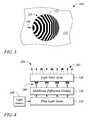
- FIG. 3illustrates a plan view of a multibeam diffraction grating 120 , according to another example consistent with the principles described herein.
- the multibeam diffraction grating 120is on a surface of a light guide 110 and includes diffractive features 122 that are both piece-wise curved and chirped.
- An example incident direction of guided light 104is illustrated by a bold arrow in FIG. 3 .
- the multibeam diffraction grating-based backlight 100may further include the light source 130 , according to some examples.
- the light source 130may be configured to provide light that, when coupled into the light guide 110 , is the guided light 104 .
- the light source 130may be substantially any source of light including, but not limited to, one or more of a light emitting diode (LED), a fluorescent light and a laser.
- the light source 130may produce a substantially monochromatic light having a narrowband spectrum denoted by a particular color.
- the color of the monochromatic lightmay be a primary color of a particular color gamut or color model (e.g., a red-green-blue (RGB) color model).
- the light source 130may be a red LED and the monochromatic light 102 is substantially the color red.
- the light source 130may be a green LED and the monochromatic light 130 is substantially green in color.
- the light source 130may be a blue LED and the monochromatic light 130 is substantially blue in color.
- the light provided by the light source 130has a substantially broadband spectrum.
- the light produced by the light source 130may be white light.
- the light source 130may be a fluorescent light that produces white light.
- the guided light 104may be light from the light source 130 that is coupled into an end or an edge of the light guide 110 .
- a lens(not illustrated) may facilitate coupling of light into the light guide 110 at the end or edge thereof, for example.
- the multibeam diffraction grating-based backlight 100is substantially transparent.
- both of the light guide 110 and the multibeam diffraction grating 120may be optically transparent in a direction orthogonal to a direction of guided light propagation in the light guide 110 , according to some examples.
- Optical transparencymay allow objects on one side of the multibeam diffraction grating-based backlight 100 to be seen from an opposite side, for example.
- an electronic displayis provided.
- the electronic displayis configured to emit modulated light beams as pixels of the electronic display.
- the emitted modulated light beamsmay be preferentially directed toward a viewing direction of the electronic display as a plurality of differently directed light beams.
- the electronic displayis a three-dimensional (3-D) electronic display (e.g., a glasses-free 3-D electronic display).
- Different ones of the modulated, differently directed light beamsmay correspond to different ‘views’ associated with the 3-D electronic display, according to various examples.
- the different ‘views’may provide a ‘glasses free’ (e.g., autostereoscopic) representation of information being displayed by the 3-D electronic display, for example.
- FIG. 4illustrates a block diagram of an electronic display 200 , according to an example consistent with the principles described herein.
- the electronic display 200 illustrated in FIG. 4is a 3-D electronic display 200 (e.g., a ‘glasses free’ 3-D electronic display) configured to emit modulated light beams 202 .
- the emitted, modulated light beams 202are illustrated as diverging (e.g., as opposed to converging) in FIG. 4 by way of example and not limitation.
- the 3-D electronic display 200 illustrated in FIG. 4includes a plate light guide 210 to guide light.
- the guided light in the plate light guide 210is a source of the light that becomes the modulated light beams 202 emitted by the 3-D electronic display 200 .
- the plate light guide 210may be substantially similar to the light guide 110 described above with respect to multibeam diffraction grating-based backlight 100 .
- the plate light guide 210may be a slab optical waveguide that is a planar sheet of dielectric material configured to guide light by total internal reflection.
- the 3-D electronic display 200 illustrated in FIG. 4further includes a multibeam diffraction grating 220 .
- the multibeam diffraction grating 220may be substantially similar to the multibeam diffraction grating 120 of the multibeam diffraction grating-based backlight 100 , described above.
- the multibeam diffraction grating 220is configured to couple out a portion of the guided light as a plurality of light beams 204 .
- the multibeam diffraction grating 220is configured to direct the light beams 204 in a corresponding plurality of different principal angular directions.
- the multibeam diffraction grating 220includes a chirped diffraction grating.
- diffractive featurese.g., grooves, ridges, etc.
- the multibeam diffraction grating 220includes a chirped diffraction grating having curved diffractive features.
- the curved diffractive featuresmay include a ridge or a groove that is curved (i.e., continuously curved or piece-wise curved) and a spacing between the curved diffractive features that may vary as a function of distance across the multibeam diffraction grating 220 .
- the 3-D electronic display 200further includes a light valve array 230 .
- the light valve array 230includes a plurality of light valves configured to modulate the differently directed light beams 204 of the plurality, according to various examples.
- the light valves of the light valve array 230modulate the differently directed light beams 204 to provide the modulated light beams 202 that are the pixels of the 3-D electronic display 200 .
- different ones of the modulated, differently directed light beams 202may correspond to different views of the 3-D electronic display.
- different types of light valves in the light valve array 230may be employed including, but not limited to, liquid crystal light valves and electrophoretic light valves. Dashed lines are used in FIG. 4 to emphasize modulation of the light beams 202 .
- the light valve array 230 employed in the 3-D displaymay be relatively thick or equivalently may be spaced apart from the multibeam diffraction grating 220 by a relatively large distance.
- the light valve array 230(e.g., using the liquid crystal light valves) may be spaced apart from the multibeam diffraction grating 220 or equivalently have a thickness that is greater than about 50 micrometers.
- the light valve array 230may be spaced apart from the multibeam diffraction grating 220 or include a thickness that is greater than about 100 micrometers. In yet other examples, the thickness or spacing may be greater than about 200 micrometers.
- a relatively thick light valve array 230 or a light valve array 230 that is spaced apart from the multibeam diffraction grating 220may be employed since the multibeam diffraction grating 220 provides light beams 204 directed in a plurality of different principal angular directions, according to various examples of the principles described herein.
- the relatively thick light valve array 230may be commercially available (e.g., a commercially available liquid crystal light valve array).
- the 3-D electronic display 200further includes a light source 240 .
- the light source 240is configured to provide light that propagates in the plate light guide 210 as the guided light.
- the guided lightis light from the light source 240 that is coupled into the edge of the plate light guide 210 , according to some examples.
- the light source 240is substantially similar to the light source 130 described above with respect to the multibeam diffraction grating-based backlight 100 .
- the light source 240may include an LED of a particular color (e.g., red, green, blue) to provide monochromatic light or a broadband light source such as, but not limited to, a fluorescent light to provide broadband light (e.g., white light).
- a particular colore.g., red, green, blue
- a broadband light sourcesuch as, but not limited to, a fluorescent light to provide broadband light (e.g., white light).
- FIG. 5illustrates a flow chart of a method 300 of electronic display operation, according to an example consistent with the principles described herein.
- the method 300 of electronic display operationincludes guiding 310 light in a light guide.
- the light guide and the guided lightmay be substantially similar to the light guide 110 and guided light 104 , described above with respect to the multibeam diffraction grating-based backlight 100 .
- the light guidemay guide 310 the guided light according to total internal reflection.
- the light guidemay be a substantially planar dielectric optical waveguide (e.g., a plate light guide), in some examples.
- the method 300 of electronic display operationfurther includes diffractively coupling out 320 a portion of the guided light using a multibeam diffraction grating.
- the multibeam diffraction gratingis located at a surface of the light guide.
- the multibeam diffraction gratingmay be formed in the surface of the light guide as grooves, ridges, etc.
- the multibeam diffraction gratingmay include a film on the light guide surface.
- the multibeam diffraction gratingis substantially similar to the multibeam diffraction grating 120 described above with respect to the multibeam diffraction grating-based backlight 100 .
- the multibeam diffraction gratingproduces a plurality of light beams from the diffractively coupled out 320 portion of the guided light.
- the method 300 of electronic display operationfurther includes diffractively redirecting 330 the light beams of the plurality away from the light guide surface.
- a light beam of the plurality that is diffractively redirected 330 away from the surfacehas a different principal angular direction from other light beams of the plurality.
- each diffractively redirected light beam of the pluralityhas a different principal angular direction relative to the other light beams of the plurality.
- Diffractively redirecting 330 the light beams away from the surfacefurther employs the multibeam diffraction grating.
- diffractively redirecting 330 the light beams of the plurality away from the surface in different principal angular directions using the multibeam diffraction gratingmay be substantially similar to the operation of the multibeam diffraction grating 120 , described above with respect to the multibeam diffraction grating-based backlight 100 .
- the multibeam diffraction gratingmay simultaneously, or substantially simultaneously, diffractively couple out 320 and diffractively redirect 330 the guided light as a plurality of light beams in accordance with the method 300 .
- the method 300 of electronic display operationfurther includes modulating 340 the light beams of the plurality of light beams using a corresponding plurality of light valves.
- the diffractively redirected 330 plurality of light beamsis modulated 340 by passing through or otherwise interacting with the corresponding plurality of light valves.
- the modulated light beamsmay form pixels of a three-dimensional (3-D) electronic display, according to some examples.
- the modulated light beamsmay provide a plurality of views of the 3-D electronic display (e.g., a glasses-free, 3-D electronic display).
- the plurality of light valves used in modulating 340 the plurality of light beamsis substantially similar to the light valve array 230 described above with respect to the 3-D electronic display 200 .
- the light valvesmay include liquid crystal light valves.
- the light valvesmay be another type of light valve including, but not limited to, an electrowetting light valve and an electrophoretic light valve.
Landscapes
- Physics & Mathematics (AREA)
- General Physics & Mathematics (AREA)
- Optics & Photonics (AREA)
- Nonlinear Science (AREA)
- Crystallography & Structural Chemistry (AREA)
- Mathematical Physics (AREA)
- Chemical & Material Sciences (AREA)
- Engineering & Computer Science (AREA)
- General Engineering & Computer Science (AREA)
- Planar Illumination Modules (AREA)
- Optical Couplings Of Light Guides (AREA)
- Optical Integrated Circuits (AREA)
- Diffracting Gratings Or Hologram Optical Elements (AREA)
- Light Guides In General And Applications Therefor (AREA)
- Liquid Crystal (AREA)
Abstract
Description
where λ, is a wavelength of the light, m is a diffraction order, d is a distance between features of the diffraction grating, θiis an angle of incidence of the light on the diffraction grating, and n is a refractive index of a material (e.g., a liquid crystal) on a side of the diffraction grating from which light is incident on the diffraction grating (i.e., ‘light-incident’ side). Equation (1) assumes that a refractive index on a side of the diffraction grating opposite the light-incident side has a refractive index of one. If the refractive index on the side opposite the light-incident side is not one, then equation (1) may be modified accordingly. Herein, the plurality of light beams produced by the multibeam diffraction grating may all have the same diffractive order m, according to various examples.
Claims (17)
Priority Applications (1)
| Application Number | Priority Date | Filing Date | Title |
|---|---|---|---|
| US14/308,689US9128226B2 (en) | 2013-07-30 | 2014-06-18 | Multibeam diffraction grating-based backlighting |
Applications Claiming Priority (2)
| Application Number | Priority Date | Filing Date | Title |
|---|---|---|---|
| PCT/US2013/052774WO2015016844A1 (en) | 2013-07-30 | 2013-07-30 | Multibeam diffraction grating-based backlighting |
| US14/308,689US9128226B2 (en) | 2013-07-30 | 2014-06-18 | Multibeam diffraction grating-based backlighting |
Related Parent Applications (1)
| Application Number | Title | Priority Date | Filing Date |
|---|---|---|---|
| PCT/US2013/052774ContinuationWO2015016844A1 (en) | 2013-07-30 | 2013-07-30 | Multibeam diffraction grating-based backlighting |
Publications (2)
| Publication Number | Publication Date |
|---|---|
| US20150036068A1 US20150036068A1 (en) | 2015-02-05 |
| US9128226B2true US9128226B2 (en) | 2015-09-08 |
Family
ID=52432216
Family Applications (3)
| Application Number | Title | Priority Date | Filing Date |
|---|---|---|---|
| US14/908,523AbandonedUS20160195664A1 (en) | 2013-07-30 | 2013-07-30 | Multibeam diffraction grating-based backlighting |
| US14/308,689ActiveUS9128226B2 (en) | 2013-07-30 | 2014-06-18 | Multibeam diffraction grating-based backlighting |
| US16/270,422ActiveUS10830939B2 (en) | 2013-07-30 | 2019-02-07 | Multibeam diffraction grating-based backlighting |
Family Applications Before (1)
| Application Number | Title | Priority Date | Filing Date |
|---|---|---|---|
| US14/908,523AbandonedUS20160195664A1 (en) | 2013-07-30 | 2013-07-30 | Multibeam diffraction grating-based backlighting |
Family Applications After (1)
| Application Number | Title | Priority Date | Filing Date |
|---|---|---|---|
| US16/270,422ActiveUS10830939B2 (en) | 2013-07-30 | 2019-02-07 | Multibeam diffraction grating-based backlighting |
Country Status (10)
| Country | Link |
|---|---|
| US (3) | US20160195664A1 (en) |
| EP (1) | EP2938919B1 (en) |
| JP (1) | JP6140838B2 (en) |
| KR (1) | KR101660911B1 (en) |
| CN (2) | CN109100887B (en) |
| ES (1) | ES2704675T3 (en) |
| PL (1) | PL2938919T3 (en) |
| PT (1) | PT2938919T (en) |
| TW (1) | TWI531823B (en) |
| WO (1) | WO2015016844A1 (en) |
Cited By (138)
| Publication number | Priority date | Publication date | Assignee | Title |
|---|---|---|---|---|
| US9557466B2 (en) | 2014-07-30 | 2017-01-31 | Leia, Inc | Multibeam diffraction grating-based color backlighting |
| US20170176669A1 (en)* | 2015-12-18 | 2017-06-22 | Samsung Electronics Co., Ltd. | Directional backlight, 3d image display apparatus having the same, and method of manufacturing the same |
| US20170351035A1 (en)* | 2014-12-29 | 2017-12-07 | Imec Vzw | Light Coupler |
| US20180128962A1 (en)* | 2016-11-08 | 2018-05-10 | Samsung Electronics Co., Ltd. | Directional backlight unit and image display apparatus including the same |
| WO2018175776A1 (en)* | 2017-03-22 | 2018-09-27 | Magic Leap, Inc. | Wearable display device utilizing a composite field of view |
| US10089516B2 (en) | 2013-07-31 | 2018-10-02 | Digilens, Inc. | Method and apparatus for contact image sensing |
| US10145533B2 (en) | 2005-11-11 | 2018-12-04 | Digilens, Inc. | Compact holographic illumination device |
| US10156681B2 (en) | 2015-02-12 | 2018-12-18 | Digilens Inc. | Waveguide grating device |
| WO2019010233A1 (en) | 2017-07-05 | 2019-01-10 | Red. Com, Llc | Video image data processing in electronic devices |
| US10180530B2 (en)* | 2015-12-09 | 2019-01-15 | Samsung Electronics Co., Ltd. | Directional backlight unit and 3D image display apparatus having the same |
| US10185154B2 (en) | 2011-04-07 | 2019-01-22 | Digilens, Inc. | Laser despeckler based on angular diversity |
| US10209517B2 (en) | 2013-05-20 | 2019-02-19 | Digilens, Inc. | Holographic waveguide eye tracker |
| US10216061B2 (en) | 2012-01-06 | 2019-02-26 | Digilens, Inc. | Contact image sensor using switchable bragg gratings |
| US10234696B2 (en) | 2007-07-26 | 2019-03-19 | Digilens, Inc. | Optical apparatus for recording a holographic device and method of recording |
| US10244230B2 (en) | 2017-03-01 | 2019-03-26 | Avalon Holographics Inc. | Directional pixel for multiple view display |
| US10241330B2 (en) | 2014-09-19 | 2019-03-26 | Digilens, Inc. | Method and apparatus for generating input images for holographic waveguide displays |
| US20190170926A1 (en)* | 2013-07-30 | 2019-06-06 | Leia Inc. | Multibeam diffraction grating-based backlighting |
| US10330777B2 (en) | 2015-01-20 | 2019-06-25 | Digilens Inc. | Holographic waveguide lidar |
| US10359736B2 (en) | 2014-08-08 | 2019-07-23 | Digilens Inc. | Method for holographic mastering and replication |
| US10373544B1 (en) | 2016-01-29 | 2019-08-06 | Leia, Inc. | Transformation from tiled to composite images |
| US10379280B2 (en) | 2016-08-30 | 2019-08-13 | Samsung Electronics Co., Ltd. | Directional backlight unit and 3D image display device having the same |
| US10423222B2 (en) | 2014-09-26 | 2019-09-24 | Digilens Inc. | Holographic waveguide optical tracker |
| US10437051B2 (en) | 2012-05-11 | 2019-10-08 | Digilens Inc. | Apparatus for eye tracking |
| US10437064B2 (en) | 2015-01-12 | 2019-10-08 | Digilens Inc. | Environmentally isolated waveguide display |
| US10459145B2 (en) | 2015-03-16 | 2019-10-29 | Digilens Inc. | Waveguide device incorporating a light pipe |
| US10531098B2 (en) | 2015-04-10 | 2020-01-07 | Red.Com, Llc | Video camera with rate control video compression |
| US10539734B2 (en) | 2016-07-22 | 2020-01-21 | Samsung Electronics Co., Ltd. | Directional backlight unit, method for manufacturing the same, and 3D image display apparatus having the same |
| US10545346B2 (en) | 2017-01-05 | 2020-01-28 | Digilens Inc. | Wearable heads up displays |
| US10551546B2 (en) | 2015-09-05 | 2020-02-04 | Leia Inc. | Multibeam diffraction grating-based display with head tracking |
| US10578793B2 (en) | 2015-05-09 | 2020-03-03 | Leia Inc. | Color-scanning grating-based backlight and electronic display using same |
| US10591756B2 (en) | 2015-03-31 | 2020-03-17 | Digilens Inc. | Method and apparatus for contact image sensing |
| US10642058B2 (en) | 2011-08-24 | 2020-05-05 | Digilens Inc. | Wearable data display |
| US10649128B2 (en) | 2016-01-30 | 2020-05-12 | Leia Inc. | Multibeam element-based backlight and display using same |
| US10670920B2 (en) | 2015-03-16 | 2020-06-02 | Leia Inc. | Unidirectional grating-based backlighting employing an angularly selective reflective layer |
| US10670876B2 (en) | 2011-08-24 | 2020-06-02 | Digilens Inc. | Waveguide laser illuminator incorporating a despeckler |
| US10678094B2 (en) | 2016-10-05 | 2020-06-09 | Leia Inc. | Polarized backlight and backlit display using the same |
| US10678053B2 (en) | 2009-04-27 | 2020-06-09 | Digilens Inc. | Diffractive projection apparatus |
| US10684404B2 (en) | 2015-01-10 | 2020-06-16 | Leia Inc. | Diffraction grating-based backlighting having controlled diffractive coupling efficiency |
| US10690851B2 (en) | 2018-03-16 | 2020-06-23 | Digilens Inc. | Holographic waveguides incorporating birefringence control and methods for their fabrication |
| US10690916B2 (en) | 2015-10-05 | 2020-06-23 | Digilens Inc. | Apparatus for providing waveguide displays with two-dimensional pupil expansion |
| US10703375B2 (en) | 2015-05-30 | 2020-07-07 | Leia Inc. | Vehicle monitoring system |
| US10705281B2 (en) | 2016-10-05 | 2020-07-07 | Leia Inc. | Mode-selectable backlight, method, and display employing directional scattering features |
| US10725317B2 (en)* | 2015-12-22 | 2020-07-28 | Svg Optronics, Co., Ltd. | Naked eye 3D laser display device |
| US10732569B2 (en) | 2018-01-08 | 2020-08-04 | Digilens Inc. | Systems and methods for high-throughput recording of holographic gratings in waveguide cells |
| US10768357B2 (en) | 2015-01-10 | 2020-09-08 | Leia Inc. | Polarization-mixing light guide and multibeam grating-based backlighting using same |
| US10788619B2 (en) | 2015-04-23 | 2020-09-29 | Leia Inc. | Dual light guide grating-based backlight and electronic display using same |
| US10798371B2 (en) | 2015-09-05 | 2020-10-06 | Leia Inc. | Multiview display with head tracking |
| US10810917B2 (en) | 2015-03-30 | 2020-10-20 | Leia Inc. | 2D/3D mode-switchable electronic display with dual layer backlight |
| US10852560B2 (en) | 2015-01-10 | 2020-12-01 | Leia Inc. | Two-dimensional/three-dimensional (2D/3D) switchable display backlight and electronic display |
| US10859768B2 (en) | 2016-03-24 | 2020-12-08 | Digilens Inc. | Method and apparatus for providing a polarization selective holographic waveguide device |
| US10890707B2 (en) | 2016-04-11 | 2021-01-12 | Digilens Inc. | Holographic waveguide apparatus for structured light projection |
| US10901212B2 (en) | 2016-01-16 | 2021-01-26 | Leia Inc. | Multibeam diffraction grating-based head-up display |
| US10914950B2 (en) | 2018-01-08 | 2021-02-09 | Digilens Inc. | Waveguide architectures and related methods of manufacturing |
| US10928564B2 (en) | 2017-03-25 | 2021-02-23 | Leia Inc. | Directional backlight, backlit display and method |
| US10928677B2 (en) | 2016-05-23 | 2021-02-23 | Leia Inc. | Diffractive multibeam element-based backlighting |
| US10942307B2 (en) | 2016-07-26 | 2021-03-09 | Leia Inc. | Bar collimator, backlight system and method |
| US10942430B2 (en) | 2017-10-16 | 2021-03-09 | Digilens Inc. | Systems and methods for multiplying the image resolution of a pixelated display |
| US10948647B2 (en) | 2015-01-19 | 2021-03-16 | Leia Inc. | Unidirectional grating-based backlighting employing a reflective island |
| US10948772B2 (en) | 2017-06-16 | 2021-03-16 | Leia Inc. | Multiview backlight, multiview display and method employing offset multibeam elements |
| US10969531B2 (en) | 2017-06-21 | 2021-04-06 | Leia Inc. | Microprism multibeam element backlight and multiview display using same |
| US10969627B2 (en) | 2017-12-21 | 2021-04-06 | Leia Inc. | Mode-selectable backlight, privacy display, and method |
| US10983340B2 (en) | 2016-02-04 | 2021-04-20 | Digilens Inc. | Holographic waveguide optical tracker |
| US11004407B2 (en) | 2017-05-14 | 2021-05-11 | Leia Inc. | Multiview backlight, display, and method employing active emitters |
| US11016228B2 (en) | 2018-01-09 | 2021-05-25 | Varian Semiconductor Equipment Associates, Inc. | System and method for forming diffracted optical element having varied gratings |
| US11048037B2 (en) | 2017-03-31 | 2021-06-29 | Leia Inc. | Backlight, multiview display and method employing tapered collimator |
| US11143810B2 (en) | 2017-04-04 | 2021-10-12 | Leia Inc. | Unilateral backlight, multiview display, and method employing slanted diffraction gratings |
| US11165895B2 (en) | 2015-12-14 | 2021-11-02 | Red.Com, Llc | Modular digital camera and cellular phone |
| US11169391B2 (en) | 2017-04-08 | 2021-11-09 | Leia Inc. | Multiview backlight, mode-switchable backlight, and 2D/3D mode-switchable display |
| US11194086B2 (en) | 2015-01-28 | 2021-12-07 | Leia Inc. | Three-dimensional (3D) electronic display |
| US11200855B2 (en) | 2017-03-25 | 2021-12-14 | Leia Inc. | Mode-switchable backlight, privacy display, and method |
| US11204457B2 (en) | 2017-05-11 | 2021-12-21 | Leia Inc. | Microstructured multibeam element backlighting |
| US11232729B2 (en)* | 2018-10-01 | 2022-01-25 | Leia Inc. | Multiview display and method with offset rows of multibeam emitters and multiview pixels |
| US11256022B2 (en) | 2018-01-27 | 2022-02-22 | Leia Inc. | Polarization recycling backlight, method and multiview display employing subwavelength gratings |
| US11310478B2 (en) | 2017-10-02 | 2022-04-19 | Leia Inc. | Multiview camera array, multiview system, and method having camera sub-arrays with a shared camera |
| US11307432B2 (en) | 2014-08-08 | 2022-04-19 | Digilens Inc. | Waveguide laser illuminator incorporating a Despeckler |
| US11307344B2 (en) | 2017-04-02 | 2022-04-19 | Leia Inc. | Dual view zone backlight, dual-mode display, and method |
| US11314099B2 (en) | 2016-10-05 | 2022-04-26 | Leia Inc. | Transparent display and method |
| US11320578B2 (en) | 2018-12-27 | 2022-05-03 | Leia Inc. | Multiview display, system, and method having dynamic color sub-pixels remapping |
| US11327236B2 (en) | 2017-09-28 | 2022-05-10 | Leia Inc. | Grating-coupled light guide, display system, and method employing optical concentration |
| US11327337B2 (en) | 2017-12-18 | 2022-05-10 | Leia Inc. | Mode-switchable backlight, display, and method |
| US11347053B2 (en) | 2017-10-27 | 2022-05-31 | Leia Inc. | Backlit transparent display, transparent display system, and method |
| US11378732B2 (en) | 2019-03-12 | 2022-07-05 | DigLens Inc. | Holographic waveguide backlight and related methods of manufacturing |
| US11378729B2 (en) | 2018-10-15 | 2022-07-05 | Leia Inc. | Backlight, multiview display and method having a grating spreader |
| US11402689B2 (en) | 2018-06-29 | 2022-08-02 | Leia Inc. | Mixed-format backlight, display, and method |
| US11402801B2 (en) | 2018-07-25 | 2022-08-02 | Digilens Inc. | Systems and methods for fabricating a multilayer optical structure |
| US11418775B2 (en) | 2018-12-20 | 2022-08-16 | Leia Inc. | Multiview display, system, and method having shiftable convergence plane |
| US11428860B2 (en) | 2018-12-08 | 2022-08-30 | Leia Inc. | Static multiview display and method employing directional light source and horizontal diffuser |
| US11442221B2 (en) | 2019-04-02 | 2022-09-13 | Leia Inc. | Multiview display alignment method and system |
| US11442222B2 (en) | 2019-08-29 | 2022-09-13 | Digilens Inc. | Evacuated gratings and methods of manufacturing |
| US11448896B2 (en) | 2017-04-04 | 2022-09-20 | Leia Inc. | Multilayer multiview display and method |
| US11448937B2 (en) | 2012-11-16 | 2022-09-20 | Digilens Inc. | Transparent waveguide display for tiling a display having plural optical powers using overlapping and offset FOV tiles |
| US11460621B2 (en) | 2012-04-25 | 2022-10-04 | Rockwell Collins, Inc. | Holographic wide angle display |
| US11467421B2 (en) | 2019-01-25 | 2022-10-11 | Leia Inc. | Multi-directional backlight, multi-user multiview display, and method |
| US11480788B2 (en) | 2015-01-12 | 2022-10-25 | Digilens Inc. | Light field displays incorporating holographic waveguides |
| US11513350B2 (en) | 2016-12-02 | 2022-11-29 | Digilens Inc. | Waveguide device with uniform output illumination |
| US11526008B2 (en) | 2017-12-18 | 2022-12-13 | Leia Inc. | Multibeam element-based head-up display, system, and method |
| US11543594B2 (en) | 2019-02-15 | 2023-01-03 | Digilens Inc. | Methods and apparatuses for providing a holographic waveguide display using integrated gratings |
| US11650359B2 (en) | 2017-09-27 | 2023-05-16 | Leia Inc. | Multicolor static multiview display and method |
| US11681143B2 (en) | 2019-07-29 | 2023-06-20 | Digilens Inc. | Methods and apparatus for multiplying the image resolution and field-of-view of a pixelated display |
| US11686898B2 (en) | 2016-01-30 | 2023-06-27 | Leia Inc. | Privacy display and dual-mode privacy display system |
| US11698605B2 (en) | 2018-10-01 | 2023-07-11 | Leia Inc. | Holographic reality system, multiview display, and method |
| US11709305B2 (en) | 2019-08-01 | 2023-07-25 | Leia Inc. | Collimated backlight, electronic display, and method employing an absorption collimator |
| US11726332B2 (en) | 2009-04-27 | 2023-08-15 | Digilens Inc. | Diffractive projection apparatus |
| US11733556B2 (en) | 2019-10-15 | 2023-08-22 | Leia Inc. | Privacy-mode backlight, privacy display, and method |
| US11747568B2 (en) | 2019-06-07 | 2023-09-05 | Digilens Inc. | Waveguides incorporating transmissive and reflective gratings and related methods of manufacturing |
| US11804188B2 (en) | 2019-03-14 | 2023-10-31 | Leia Inc. | Mode-switchable backlight, privacy display, and method employing emitter arrays |
| US11810525B2 (en) | 2019-03-17 | 2023-11-07 | Leia Inc. | Dual view zone backlight, dual-mode display, and method employing directional emitters |
| US11846800B2 (en) | 2019-04-29 | 2023-12-19 | Leia Inc. | Multiview display and method having shifted color sub-pixels |
| US11906758B2 (en) | 2019-08-27 | 2024-02-20 | Leia Inc. | Multiview backlight, display, and method employing an optical diffuser |
| US11909948B2 (en) | 2019-09-12 | 2024-02-20 | Leia Inc. | Multiview backlight, multiview display, and method employing reflective multibeam elements |
| US11988863B2 (en) | 2019-10-31 | 2024-05-21 | Leia Inc. | Multibeam backlight, multiview display, and method having shaped-edge multibeam elements |
| US12032178B2 (en) | 2018-10-31 | 2024-07-09 | Leia Inc. | Multiview backlight, display, and method having optical mask elements |
| US12072577B2 (en) | 2020-11-09 | 2024-08-27 | Leia Inc. | Horizontal parallax multiview backlight, display, and method |
| US12078816B2 (en) | 2018-08-13 | 2024-09-03 | Leia Inc. | Grating collimator, backlight system, and method employing a light-recycling light source |
| US12092914B2 (en) | 2018-01-08 | 2024-09-17 | Digilens Inc. | Systems and methods for manufacturing waveguide cells |
| US12111489B2 (en) | 2019-10-15 | 2024-10-08 | Leia Inc. | Multibeam backlight, multiview display, and method with diffraction grating filling fraction |
| US12124073B2 (en) | 2019-04-28 | 2024-10-22 | Leia Inc. | Method of fabricating diffractive backlight |
| US12140764B2 (en) | 2019-02-15 | 2024-11-12 | Digilens Inc. | Wide angle waveguide display |
| US12140777B2 (en) | 2017-01-06 | 2024-11-12 | Leia Inc. | Static multiview display and method |
| US12140791B2 (en) | 2019-04-22 | 2024-11-12 | Leia Inc. | Multi-zone backlight, multiview display, and method |
| US12158612B2 (en) | 2021-03-05 | 2024-12-03 | Digilens Inc. | Evacuated periodic structures and methods of manufacturing |
| US12159372B2 (en) | 2020-03-01 | 2024-12-03 | Leia Inc. | Systems and methods of multiview style transfer |
| US12164119B2 (en) | 2018-11-05 | 2024-12-10 | Leia Inc. | Multiview display and method |
| US12177414B2 (en) | 2018-08-26 | 2024-12-24 | Leia Inc. | Multiview display, system, and method with user tracking |
| US12189168B2 (en) | 2019-08-25 | 2025-01-07 | Leai Inc. | Backlight scattering element, multiview display, and method having high-index light guide layer |
| US12196983B2 (en) | 2019-02-16 | 2025-01-14 | Leia Inc. | Multiview display and method having light control film |
| US12204137B2 (en) | 2021-06-28 | 2025-01-21 | Leia Inc. | Multiview backlight, display, and method with reflective sub-elements having varying protrusion distances |
| US12210153B2 (en) | 2019-01-14 | 2025-01-28 | Digilens Inc. | Holographic waveguide display with light control layer |
| US12216296B2 (en) | 2018-06-29 | 2025-02-04 | Leia Inc. | Multiview display and method with dynamically reconfigurable multiview pixels |
| US12222499B2 (en) | 2020-12-21 | 2025-02-11 | Digilens Inc. | Eye glow suppression in waveguide based displays |
| US12306585B2 (en) | 2018-01-08 | 2025-05-20 | Digilens Inc. | Methods for fabricating optical waveguides |
| US12313872B2 (en) | 2020-03-02 | 2025-05-27 | Leia Inc. | Static-image augmented privacy display, mode-switchable privacy display system, and method |
| US12316821B2 (en) | 2020-09-21 | 2025-05-27 | Leia Inc. | Multiview display system and method with adaptive background |
| US12334025B2 (en) | 2019-04-22 | 2025-06-17 | Leia Spv Llc | Systems and methods of enhancing quality of multiview images using a multimode display |
| US12345900B2 (en) | 2021-12-07 | 2025-07-01 | Leia Inc. | Time-multiplexed multiview backlight, multiview display and method |
| US12395618B2 (en) | 2020-12-07 | 2025-08-19 | Leia Spv Llc | Real-time multiview video conversion method and system |
| US12399326B2 (en) | 2021-01-07 | 2025-08-26 | Digilens Inc. | Grating structures for color waveguides |
| US12397477B2 (en) | 2019-02-05 | 2025-08-26 | Digilens Inc. | Methods for compensating for optical surface nonuniformity |
Families Citing this family (61)
| Publication number | Priority date | Publication date | Assignee | Title |
|---|---|---|---|---|
| CN105700269B (en)* | 2016-04-11 | 2019-05-03 | 京东方科技集团股份有限公司 | a display device |
| US9389415B2 (en) | 2012-04-27 | 2016-07-12 | Leia Inc. | Directional pixel for use in a display screen |
| US9459461B2 (en) | 2012-05-31 | 2016-10-04 | Leia Inc. | Directional backlight |
| US9201270B2 (en) | 2012-06-01 | 2015-12-01 | Leia Inc. | Directional backlight with a modulation layer |
| US9298168B2 (en) | 2013-01-31 | 2016-03-29 | Leia Inc. | Multiview 3D wrist watch |
| CN107111059B (en)* | 2015-01-10 | 2020-10-13 | 镭亚股份有限公司 | Grating-coupled light guide |
| PT3326358T (en) | 2015-02-27 | 2022-11-25 | Leia Inc | Multiview camera |
| KR102364848B1 (en)* | 2015-08-20 | 2022-02-18 | 삼성전자주식회사 | Curved backlight unit and curved display apparatus including the same |
| JP6865212B2 (en)* | 2015-09-05 | 2021-04-28 | レイア、インコーポレイテッドLeia Inc. | Supersampled 3D display with improved angular resolution |
| WO2017039725A1 (en) | 2015-09-05 | 2017-03-09 | Leia Inc. | Dual-direction collimator |
| JP6779984B2 (en)* | 2015-09-05 | 2020-11-04 | レイア、インコーポレイテッドLeia Inc. | Condensing backlight and near-eye display system using it |
| KR102274749B1 (en)* | 2015-09-05 | 2021-07-08 | 레이아 인코포레이티드 | Multicolor grid-coupled backlighting |
| US10802212B2 (en)* | 2015-09-05 | 2020-10-13 | Leia Inc. | Angular subpixel rendering multiview display using shifted multibeam elements |
| ES2905638T3 (en)* | 2015-09-05 | 2022-04-11 | Leia Inc | Dual surface collimator and 3D electronic display employing network-based backlight using this collimator |
| CN107923600B (en)* | 2015-09-05 | 2020-04-14 | 镭亚股份有限公司 | Rendering multiview display angular subpixels using shifted multibeam diffraction gratings |
| CN108027477B (en)* | 2015-09-05 | 2020-10-13 | 镭亚股份有限公司 | Time-division multiplexing backlight and multi-view display using the same |
| KR102348588B1 (en)* | 2015-10-16 | 2022-01-07 | 레이아 인코포레이티드 | Multibeam diffraction grating-based near-eye display |
| CN106959551B (en)* | 2016-01-08 | 2023-12-19 | 京东方科技集团股份有限公司 | Display device and driving method thereof |
| KR102581465B1 (en) | 2016-01-12 | 2023-09-21 | 삼성전자주식회사 | Three-dimensional image display apparatus including the diffractive color filter |
| CN105425409B (en)* | 2016-01-19 | 2017-09-19 | 苏州苏大维格光电科技股份有限公司 | A projection-type naked-eye 3D display device and its colorized display device |
| KR102526751B1 (en) | 2016-01-25 | 2023-04-27 | 삼성전자주식회사 | Directional backlight unit, three dimensional image display apparatus, and method of displaying three dimensional image display |
| US10613376B2 (en) | 2016-01-28 | 2020-04-07 | Hewlett Packard Enterprise Development Lp | Augmented reality see-through display |
| JP6776359B2 (en)* | 2016-01-30 | 2020-10-28 | レイア、インコーポレイテッドLeia Inc. | Multi-beam element backlighting with convergent view |
| US9830755B2 (en) | 2016-02-17 | 2017-11-28 | Jvis-Usa, Llc | System including a hand-held communication device having low and high power settings for remotely controlling the position of a door of a land vehicle and key fob for use in the system |
| US10284822B2 (en) | 2016-02-17 | 2019-05-07 | Jvis-Usa, Llc | System for enhancing the visibility of a ground surface adjacent to a land vehicle |
| EP3433650B1 (en)* | 2016-03-23 | 2025-04-23 | LEIA Inc. | Grating-based backlight employing reflective grating islands |
| CN105652511B (en)* | 2016-04-11 | 2019-06-07 | 京东方科技集团股份有限公司 | A kind of display device |
| ES2906627T3 (en)* | 2016-06-08 | 2022-04-19 | Leia Inc | Multiview display rendering angular subpixels using offset multibeam elements |
| CN106094342A (en)* | 2016-08-22 | 2016-11-09 | 京东方科技集团股份有限公司 | A kind of backlight module, display device and display packing |
| KR102646789B1 (en) | 2016-09-22 | 2024-03-13 | 삼성전자주식회사 | Directional backlight unit and three-dimensional image display apparatus including the same |
| KR102608465B1 (en)* | 2016-10-05 | 2023-12-01 | 삼성전자주식회사 | Display apparatus and method for designing display apparatus |
| KR102736293B1 (en) | 2016-10-25 | 2024-11-29 | 삼성전자주식회사 | Directional backlight unit and three-dimensional image display apparatus including the same |
| TWI618957B (en)* | 2016-11-07 | 2018-03-21 | 雷亞有限公司 | A dual-direction optical collimator and a method, backlight and three-dimensional(3d) electronic display using same |
| KR102654870B1 (en) | 2016-11-09 | 2024-04-05 | 삼성전자주식회사 | Backlight unit for 3D image display and method of manufacturing the backlight unit |
| KR20180059205A (en)* | 2016-11-25 | 2018-06-04 | 삼성전자주식회사 | Directional backlight unit, 3D image display apparatus having the same, and method of manufacturing the same |
| FR3060140B1 (en)* | 2016-12-13 | 2019-07-05 | Valeo Comfort And Driving Assistance | HIGH HEAD DISPLAY |
| KR102348580B1 (en)* | 2016-12-28 | 2022-01-07 | 레이아 인코포레이티드 | Multi-view backlighting with fluorescent multi-beam elements |
| CN110168280A (en)* | 2016-12-28 | 2019-08-23 | 镭亚股份有限公司 | Multi-view display with reflective support structure |
| CA3045328C (en) | 2017-01-30 | 2021-08-03 | Leia Inc. | Multiview backlighting employing plasmonic multibeam elements |
| US11016235B2 (en)* | 2017-02-28 | 2021-05-25 | Leia Inc. | Multiview backlighting having a color-tailored emission pattern |
| CN106707624A (en)* | 2017-03-10 | 2017-05-24 | 京东方科技集团股份有限公司 | Display element, backlight source and display device |
| US10854146B1 (en) | 2017-04-28 | 2020-12-01 | Cloudminds (Shenzhen) Robotics Systems Co., Ltd. | Directional optical waveguide, directional backlight module, and display device |
| WO2018226235A1 (en)* | 2017-06-08 | 2018-12-13 | Leia Inc. | Light source and multiview backlight using the same |
| WO2019017960A1 (en)* | 2017-07-21 | 2019-01-24 | Leia Inc. | Multibeam element-based backlight with microlens and display using same |
| WO2019037020A1 (en)* | 2017-08-24 | 2019-02-28 | 冯艳 | Four-dimensional multi-plane broadband imaging system based on non-reentry quadratically distorted (nrqd) grating and grism |
| US10929667B2 (en)* | 2017-10-13 | 2021-02-23 | Corning Incorporated | Waveguide-based optical systems and methods for augmented reality systems |
| JP7480038B2 (en)* | 2017-11-18 | 2024-05-09 | レイア、インコーポレイテッド | BAR COLLIMATOR, BACKLIGHT SYSTEM, AND METHOD - Patent application |
| CN108089253B (en)* | 2017-12-15 | 2019-06-25 | 京东方科技集团股份有限公司 | Light collimator apparatus, backlight module and display device |
| FI128882B (en)* | 2017-12-22 | 2021-02-15 | Dispelix Oy | Optical waveguide and diffractive waveguide display |
| JP7217281B2 (en)* | 2018-03-01 | 2023-02-02 | レイア、インコーポレイテッド | Method using static multi-view display and collimated guided light |
| TWI657295B (en)* | 2018-03-02 | 2019-04-21 | 友達光電股份有限公司 | Backlight module with light modulation device |
| EP3735610B1 (en)* | 2018-03-15 | 2024-01-10 | LEIA Inc. | Horizontal parallax multiview display and method having slanted multibeam columns |
| CN108646338B (en)* | 2018-07-02 | 2019-12-31 | 京东方科技集团股份有限公司 | A kind of backlight module and display device |
| CN108845460B (en)* | 2018-08-15 | 2021-01-29 | 京东方科技集团股份有限公司 | A backlight module and display device |
| US10598938B1 (en)* | 2018-11-09 | 2020-03-24 | Facebook Technologies, Llc | Angular selective grating coupler for waveguide display |
| CN110161751A (en)* | 2019-05-23 | 2019-08-23 | 京东方科技集团股份有限公司 | Backlight module and display device |
| US11137534B2 (en) | 2019-06-26 | 2021-10-05 | Synaptics Incorporated | Systems and methods for optical imaging based on diffraction gratings |
| CN110426871B (en)* | 2019-08-07 | 2022-06-07 | 京东方科技集团股份有限公司 | A backlight adjustment structure and display device |
| CN114846357A (en)* | 2019-12-30 | 2022-08-02 | 鲁姆斯有限公司 | Detection and ranging system using optical waveguide |
| JP2020187762A (en)* | 2020-07-02 | 2020-11-19 | レイア、インコーポレイテッドLeia Inc. | Vehicle monitoring system |
| CN118043727A (en)* | 2021-09-25 | 2024-05-14 | 镭亚股份有限公司 | Static color multiview display and method |
Citations (81)
| Publication number | Priority date | Publication date | Assignee | Title |
|---|---|---|---|---|
| US5184848A (en) | 1989-08-31 | 1993-02-09 | Dai Nippon Insatsu Kabushiki Kaisha | Hologram calendar |
| US5301062A (en) | 1991-01-29 | 1994-04-05 | Toppan Printing Co., Ltd. | Display having diffraction grating pattern |
| US5615024A (en) | 1992-08-11 | 1997-03-25 | Sharp Kabushiki Kaisha | Color display device with chirped diffraction gratings |
| US5617248A (en) | 1994-04-18 | 1997-04-01 | Toppan Printing Co., Ltd. | Diffraction grating array and display having a diffraction grating |
| US5721598A (en) | 1995-12-26 | 1998-02-24 | Hughes Electronics | High efficiency, high color purity, on-axis holographic color filter and full-color liquid crystal display |
| WO1999008257A1 (en) | 1997-08-05 | 1999-02-18 | Allan John Davie | Liquid crystal controlled display apparatus |
| CN1213097A (en) | 1998-10-29 | 1999-04-07 | 厦门大学 | Making tomographic combined three-D holograph display device for medical image diagnosis |
| US5926294A (en) | 1995-12-12 | 1999-07-20 | Sharp Kabushiki Kaisha | Three-dimensional image display device having an elementary hologram panel and method for manufacturing the elementary hologram panel |
| JPH11326545A (en) | 1998-05-11 | 1999-11-26 | Koji Ono | Three-dimensional clock |
| US6158884A (en) | 1998-06-26 | 2000-12-12 | Motorola, Inc. | Integrated communicative watch |
| US20020008834A1 (en)* | 1997-11-13 | 2002-01-24 | Seiji Suzuki | Liquid crystal display device and method of manufacturing the same |
| WO2002042821A1 (en) | 2000-11-27 | 2002-05-30 | Advanced Interfaces, Llc | Integrated optical multiplexer and demultiplexer |
| US20020075445A1 (en) | 2000-08-29 | 2002-06-20 | Dabrowski Roman S. | Liquid crystal device and a liquid crystal material |
| US6437920B1 (en) | 1995-06-07 | 2002-08-20 | Jacob N. Wohlstadter | Three Dimensional imaging system |
| US6667819B2 (en) | 1996-04-15 | 2003-12-23 | Dai Nippon Printing Co., Ltd. | Reflection type diffuse hologram, hologram for reflection hologram color filters, etc., and reflection type display device using such holograms |
| US20040130879A1 (en) | 2003-01-07 | 2004-07-08 | Samsung Electronics Co., Ltd. | Backlight unit |
| US20040156589A1 (en) | 2003-02-11 | 2004-08-12 | Luxtera, Inc | Optical waveguide grating coupler incorporating reflective optical elements and anti-reflection elements |
| US20040156182A1 (en) | 1999-05-28 | 2004-08-12 | Leo Hatjasalo | Light panel |
| US20050041174A1 (en) | 2003-08-19 | 2005-02-24 | International Business Machines Corporation | Color filterless display device, optical element, and manufacture |
| US20050073627A1 (en) | 2001-09-28 | 2005-04-07 | Takashi Akiyama | Liquid crystal display device |
| US20050140832A1 (en) | 2003-12-31 | 2005-06-30 | Ron Goldman | Laser projection display |
| US6980271B2 (en) | 2002-08-01 | 2005-12-27 | Nec Lcd Technologies, Ltd. | Semi-transmissive LCD device having a reflector with irregularity pattern and method of fabricating same |
| US20060104570A1 (en) | 2004-11-15 | 2006-05-18 | Tim Rausch | Coupling grating for focusing light within a waveguide for heat assisted magnetic recording |
| JP2007033200A (en) | 2005-07-26 | 2007-02-08 | Sony Corp | Wrist watch, display method of wrist watch, and program |
| US20070213955A1 (en) | 2005-12-14 | 2007-09-13 | Naoto Ishida | Wrist watch, display method of wrist watch, and program |
| US20070236801A1 (en) | 2006-03-28 | 2007-10-11 | Deep Light, Llc | Time-multiplexed 3D display system with beam splitter |
| US20070279367A1 (en) | 2004-01-26 | 2007-12-06 | Adrian Kitai | Tiled Optical Fiber Display |
| US20070298533A1 (en) | 2006-06-26 | 2007-12-27 | Micron Technology, Inc. | Method and apparatus providing imager pixel array with grating structure and imager device containing the same |
| US20080204873A1 (en) | 2007-02-23 | 2008-08-28 | Strategic Patent Acquisitions Llc | Techniques for three dimensional displays |
| US20080204663A1 (en) | 2004-05-26 | 2008-08-28 | Tibor Balogh | Method And Apparatus For Generating 3D Images |
| US20080285307A1 (en) | 2007-05-16 | 2008-11-20 | Aylward Peter T | Lcd displays with light redirection |
| US20090016168A1 (en) | 2007-07-12 | 2009-01-15 | Emily Smith | Timepiece Device |
| JP2009053499A (en) | 2007-08-28 | 2009-03-12 | Fuji Xerox Co Ltd | Optical modulator and optical modulation module |
| US20090207342A1 (en) | 2006-05-18 | 2009-08-20 | Panasonic Corporation | Planar light source device and liquid crystal display device |
| US20090213300A1 (en)* | 2005-12-21 | 2009-08-27 | Casio Computer Co., Ltd. | Surface light source capable of changing range of spread angle of exit light, and liquid crystal display apparatus using this surface light source |
| US20090290837A1 (en) | 2008-05-22 | 2009-11-26 | The Chinese University Of Hong Kong | Optical devices for coupling of light |
| US7626643B2 (en) | 2003-11-07 | 2009-12-01 | Koninklijke Philips Electronics N.V. | Waveguide for autostereoscopic display having a plurality of switchable portions of diffusive material within the waveguide for providing either scattering or light-transmissive light to the display |
| JP2009288718A (en) | 2008-05-30 | 2009-12-10 | Kyoto Institute Of Technology | Resonance grating coupler |
| US20090322986A1 (en) | 2008-06-30 | 2009-12-31 | Chunghwa Picture Tubes, Ltd. | Color light guide panel and liquid crystal display |
| US20100103485A1 (en) | 2006-10-26 | 2010-04-29 | Seereal Technologies S.A. | Holographic display device |
| US20100118117A1 (en) | 2006-10-26 | 2010-05-13 | Seereal Technologies S.A. | 3d content generation system |
| US20100123952A1 (en) | 2008-11-18 | 2010-05-20 | Industrial Technology Research Institute | Stereoscopic image display apparatus |
| US7742120B2 (en) | 2002-05-08 | 2010-06-22 | Shearline Precision Engineering Limited | Image display device |
| US7773849B2 (en) | 2004-12-14 | 2010-08-10 | Oms Displays Ltd. | Device and method for optical resizing and backlighting |
| US20100207964A1 (en) | 2007-06-14 | 2010-08-19 | Jyrki Kimmel | Displays with integrated backlighting |
| US20100284085A1 (en) | 2006-09-28 | 2010-11-11 | Nokia Corporation | Beam expansion with three-dimensional diffractive elements |
| US20100289870A1 (en) | 2009-05-13 | 2010-11-18 | Seereal Technologies S.A. | 3D Display Device with Controllable Device for Tracking Visibility Regions |
| US7859947B2 (en) | 2000-10-31 | 2010-12-28 | Sony Corporation | Watch information content distribution processing system, information distribution apparatus, information distribution system, hand held terminal device, information recording medium, and information processing method |
| US20110002143A1 (en) | 2006-12-28 | 2011-01-06 | Nokia Corporation | Light guide plate and a method of manufacturing thereof |
| JP2011029161A (en) | 2009-06-26 | 2011-02-10 | Sumitomo Chemical Co Ltd | Three-dimensional display device |
| US7903332B2 (en) | 2004-10-13 | 2011-03-08 | Koninklijke Philips Electronics N.V. | Stereoscopic display apparatus |
| US20110141395A1 (en)* | 2008-07-22 | 2011-06-16 | Sharp Kabushiki Kaisha | Backlight unit and liquid crystal display device |
| US20110149596A1 (en) | 2009-12-21 | 2011-06-23 | Fu Zhun Precision Industry (Shen Zhen) Co., Ltd. | Led lamp having light guide |
| US20110157667A1 (en) | 2008-06-26 | 2011-06-30 | Lilian Lacoste | Holographic Image Display Systems |
| US20110182570A1 (en) | 2010-01-25 | 2011-07-28 | J Touch Corporation | Three-dimensional video imaging device |
| US8026997B2 (en) | 2009-01-28 | 2011-09-27 | Sharp Laboratories Of America, Inc. | Area active backlight with steerable light source |
| US20110254916A1 (en) | 2008-12-25 | 2011-10-20 | Afc Technology Co., Ltd. | Holographic projection real-time 3d display system and method |
| US20110304784A1 (en) | 2010-06-11 | 2011-12-15 | Omron Corporation | Area light source device and stereoscopic display device |
| US20110308445A1 (en) | 2009-02-15 | 2011-12-22 | Shiri Avda | Means and method for calculating, measuring and displaying a measurable quantity |
| US20120013962A1 (en) | 2010-07-19 | 2012-01-19 | Omega Optics, Inc. | Two-dimensional surface normal slow-light photonic crystal waveguide optical phased array |
| US20120075698A1 (en) | 2010-09-27 | 2012-03-29 | Sony Corporation | Light source device and stereoscopic display |
| US20120120213A1 (en) | 2010-11-17 | 2012-05-17 | Sony Corporation | Stereoscopic display device |
| US20120127573A1 (en) | 2010-11-19 | 2012-05-24 | Reald Inc. | Directional flat illuminators |
| US20120127751A1 (en) | 2008-11-10 | 2012-05-24 | Nokia Corporation | Diffractive backlight structure |
| WO2012069071A1 (en) | 2010-11-24 | 2012-05-31 | Fraunhofer-Gesellschaft zur Föderung der angewandten Forschung e.V. | Method for compensating a misalignment between a subpixel array of a display and an optical grating and autostereoscopic display |
| US20120176665A1 (en) | 2011-01-11 | 2012-07-12 | Hoon Song | 3-dimensional image display apparatus |
| US20120249934A1 (en) | 2011-03-31 | 2012-10-04 | Chi Mei Corporation | Display apparatus and liquid crystal display device |
| US20120250141A1 (en) | 2011-03-30 | 2012-10-04 | Infovision Optoelectronics (Kunshan) Co. Ltd. | Transmission mode switching device and 2d/3d switchable display apparatus |
| US20130057539A1 (en) | 2011-09-02 | 2013-03-07 | Lg Display Co., Ltd. | Barrier Panel and Three Dimensional Image Display Device Using the Same |
| US20130082980A1 (en) | 2011-09-29 | 2013-04-04 | Qualcomm Mems Technolgies, Inc. | Optical touch device with pixilated light-turning features |
| WO2013162609A1 (en) | 2012-04-27 | 2013-10-31 | Hewlett-Packard Development Company, L.P. | Directional pixel for use in a display screen |
| WO2013180737A1 (en) | 2012-06-01 | 2013-12-05 | Hewlett-Packard Development Company, L.P. | Directional backlight with a modulation layer |
| WO2013180725A1 (en) | 2012-05-31 | 2013-12-05 | Hewlett-Packard Development Company, L.P. | Directional backlight |
| US8681423B1 (en) | 2013-01-29 | 2014-03-25 | Hewlett-Packard Development Company, L.P. | Light modulation employing fluid movement |
| WO2014120194A1 (en) | 2013-01-31 | 2014-08-07 | Leia Inc. | Multiview 3d wrist watch |
| US20140293759A1 (en) | 2013-01-31 | 2014-10-02 | Leia Inc. | Multiview 3d wrist watch |
| US20140300960A1 (en) | 2012-05-31 | 2014-10-09 | Leia Inc. | Directional backlight |
| US20140300947A1 (en) | 2012-04-27 | 2014-10-09 | Leia Inc. | Directional pixel for use in a display screen |
| US20140300840A1 (en) | 2012-06-01 | 2014-10-09 | Leia Inc. | Directional backlight with a modulation layer |
| US8915635B2 (en) | 2013-03-13 | 2014-12-23 | Hewlett-Packard Development Company, L.P. | Backlight having dual collimating reflectors |
| US20150016777A1 (en) | 2012-06-11 | 2015-01-15 | Magic Leap, Inc. | Planar waveguide apparatus with diffraction element(s) and system employing same |
Family Cites Families (16)
| Publication number | Priority date | Publication date | Assignee | Title |
|---|---|---|---|---|
| DE3536497A1 (en)* | 1984-10-16 | 1986-04-17 | Mitsubishi Denki K.K., Tokio/Tokyo | DEVICE FOR DETECTING FOCUSING ERRORS IN A HEAD ARRANGEMENT FOR OPTICAL DISCS |
| JP3778966B2 (en) | 1995-07-31 | 2006-05-24 | 凸版印刷株式会社 | Full color image display device |
| JPH09284684A (en)* | 1996-04-17 | 1997-10-31 | Hitachi Ltd | Single-panel color liquid crystal display device |
| US6295104B1 (en)* | 1998-05-26 | 2001-09-25 | Minebea Co., Ltd. | Front illuminating system with layer between light guide and LCD |
| CN1619373A (en)* | 2003-11-17 | 2005-05-25 | 鸿富锦精密工业(深圳)有限公司 | Light guide plate and backlight module |
| TWI254166B (en)* | 2004-05-25 | 2006-05-01 | Au Optronics Corp | 3D display system and method |
| EP1834320B1 (en) | 2004-12-23 | 2017-08-30 | Dolby Laboratories Licensing Corporation | Wide color gamut displays |
| CN1932602A (en)* | 2005-09-14 | 2007-03-21 | 鸿富锦精密工业(深圳)有限公司 | Light-conducting plate |
| JP5010527B2 (en)* | 2007-06-04 | 2012-08-29 | 住友化学株式会社 | Light guide plate unit, surface light source device, and liquid crystal display device |
| JP5010549B2 (en) | 2008-07-25 | 2012-08-29 | 株式会社東芝 | Liquid crystal display |
| US8251563B2 (en)* | 2009-05-29 | 2012-08-28 | Sharp Kabushiki Kaisha | Polarized diffractive backlight |
| JP2009295598A (en) | 2009-09-18 | 2009-12-17 | Toppan Printing Co Ltd | Light guide plate, and illuminating device and display using the same |
| KR101680770B1 (en) | 2010-07-09 | 2016-11-29 | 삼성전자주식회사 | Back light unit and display apparatus employing the same |
| CN202126538U (en) | 2011-06-17 | 2012-01-25 | 中航华东光电有限公司 | High-definition LCD (Liquid Crystal Display) auto-stereoscopic display with cylindrical grating |
| PL2938919T3 (en)* | 2013-07-30 | 2019-06-28 | Leia Inc. | Multibeam diffraction grating-based backlighting |
| US9557466B2 (en) | 2014-07-30 | 2017-01-31 | Leia, Inc | Multibeam diffraction grating-based color backlighting |
- 2013
- 2013-07-30PLPL13890862Tpatent/PL2938919T3/enunknown
- 2013-07-30PTPT13890862Tpatent/PT2938919T/enunknown
- 2013-07-30KRKR1020147027184Apatent/KR101660911B1/enactiveActive
- 2013-07-30ESES13890862Tpatent/ES2704675T3/enactiveActive
- 2013-07-30JPJP2015552621Apatent/JP6140838B2/enactiveActive
- 2013-07-30USUS14/908,523patent/US20160195664A1/ennot_activeAbandoned
- 2013-07-30CNCN201810884795.5Apatent/CN109100887B/enactiveActive
- 2013-07-30EPEP13890862.9Apatent/EP2938919B1/enactiveActive
- 2013-07-30CNCN201380022163.3Apatent/CN104508353B/enactiveActive
- 2013-07-30WOPCT/US2013/052774patent/WO2015016844A1/enactiveApplication Filing
- 2014
- 2014-06-18USUS14/308,689patent/US9128226B2/enactiveActive
- 2014-06-26TWTW103122128Apatent/TWI531823B/enactive
- 2019
- 2019-02-07USUS16/270,422patent/US10830939B2/enactiveActive
Patent Citations (87)
| Publication number | Priority date | Publication date | Assignee | Title |
|---|---|---|---|---|
| US5184848A (en) | 1989-08-31 | 1993-02-09 | Dai Nippon Insatsu Kabushiki Kaisha | Hologram calendar |
| US5301062A (en) | 1991-01-29 | 1994-04-05 | Toppan Printing Co., Ltd. | Display having diffraction grating pattern |
| US5615024A (en) | 1992-08-11 | 1997-03-25 | Sharp Kabushiki Kaisha | Color display device with chirped diffraction gratings |
| US5617248A (en) | 1994-04-18 | 1997-04-01 | Toppan Printing Co., Ltd. | Diffraction grating array and display having a diffraction grating |
| US6437920B1 (en) | 1995-06-07 | 2002-08-20 | Jacob N. Wohlstadter | Three Dimensional imaging system |
| US5926294A (en) | 1995-12-12 | 1999-07-20 | Sharp Kabushiki Kaisha | Three-dimensional image display device having an elementary hologram panel and method for manufacturing the elementary hologram panel |
| US5721598A (en) | 1995-12-26 | 1998-02-24 | Hughes Electronics | High efficiency, high color purity, on-axis holographic color filter and full-color liquid crystal display |
| US6667819B2 (en) | 1996-04-15 | 2003-12-23 | Dai Nippon Printing Co., Ltd. | Reflection type diffuse hologram, hologram for reflection hologram color filters, etc., and reflection type display device using such holograms |
| WO1999008257A1 (en) | 1997-08-05 | 1999-02-18 | Allan John Davie | Liquid crystal controlled display apparatus |
| US20020008834A1 (en)* | 1997-11-13 | 2002-01-24 | Seiji Suzuki | Liquid crystal display device and method of manufacturing the same |
| JPH11326545A (en) | 1998-05-11 | 1999-11-26 | Koji Ono | Three-dimensional clock |
| US6158884A (en) | 1998-06-26 | 2000-12-12 | Motorola, Inc. | Integrated communicative watch |
| CN1213097A (en) | 1998-10-29 | 1999-04-07 | 厦门大学 | Making tomographic combined three-D holograph display device for medical image diagnosis |
| US20040156182A1 (en) | 1999-05-28 | 2004-08-12 | Leo Hatjasalo | Light panel |
| US20020075445A1 (en) | 2000-08-29 | 2002-06-20 | Dabrowski Roman S. | Liquid crystal device and a liquid crystal material |
| US7859947B2 (en) | 2000-10-31 | 2010-12-28 | Sony Corporation | Watch information content distribution processing system, information distribution apparatus, information distribution system, hand held terminal device, information recording medium, and information processing method |
| US6490393B1 (en) | 2000-11-27 | 2002-12-03 | Advanced Interfaces, Llc | Integrated optical multiplexer and demultiplexer for wavelength division transmission of information |
| CN1479878A (en) | 2000-11-27 | 2004-03-03 | �����ι�˾ | Integrated Optical Multiplexer and Demultiplexer |
| US6718093B2 (en) | 2000-11-27 | 2004-04-06 | Advanced Interfaces, Llc | Integrated optical multiplexer and demultiplexer for wavelength division transmission of information |
| US20030086649A1 (en) | 2000-11-27 | 2003-05-08 | Advanced Interfaces, Inc. | Integrated optical multiplexer and demultiplexer for wavelength division transmission of information |
| WO2002042821A1 (en) | 2000-11-27 | 2002-05-30 | Advanced Interfaces, Llc | Integrated optical multiplexer and demultiplexer |
| US20050073627A1 (en) | 2001-09-28 | 2005-04-07 | Takashi Akiyama | Liquid crystal display device |
| US7742120B2 (en) | 2002-05-08 | 2010-06-22 | Shearline Precision Engineering Limited | Image display device |
| US6980271B2 (en) | 2002-08-01 | 2005-12-27 | Nec Lcd Technologies, Ltd. | Semi-transmissive LCD device having a reflector with irregularity pattern and method of fabricating same |
| US20040130879A1 (en) | 2003-01-07 | 2004-07-08 | Samsung Electronics Co., Ltd. | Backlight unit |
| CN1517760A (en) | 2003-01-07 | 2004-08-04 | 三星电子株式会社 | backlight unit |
| US7044628B2 (en) | 2003-01-07 | 2006-05-16 | Samsung Electronics Co., Ltd. | Backlight unit |
| US20040156589A1 (en) | 2003-02-11 | 2004-08-12 | Luxtera, Inc | Optical waveguide grating coupler incorporating reflective optical elements and anti-reflection elements |
| US20050041174A1 (en) | 2003-08-19 | 2005-02-24 | International Business Machines Corporation | Color filterless display device, optical element, and manufacture |
| US7626643B2 (en) | 2003-11-07 | 2009-12-01 | Koninklijke Philips Electronics N.V. | Waveguide for autostereoscopic display having a plurality of switchable portions of diffusive material within the waveguide for providing either scattering or light-transmissive light to the display |
| US20050140832A1 (en) | 2003-12-31 | 2005-06-30 | Ron Goldman | Laser projection display |
| US20070279367A1 (en) | 2004-01-26 | 2007-12-06 | Adrian Kitai | Tiled Optical Fiber Display |
| US20080204663A1 (en) | 2004-05-26 | 2008-08-28 | Tibor Balogh | Method And Apparatus For Generating 3D Images |
| US7903332B2 (en) | 2004-10-13 | 2011-03-08 | Koninklijke Philips Electronics N.V. | Stereoscopic display apparatus |
| US20060104570A1 (en) | 2004-11-15 | 2006-05-18 | Tim Rausch | Coupling grating for focusing light within a waveguide for heat assisted magnetic recording |
| US7773849B2 (en) | 2004-12-14 | 2010-08-10 | Oms Displays Ltd. | Device and method for optical resizing and backlighting |
| JP2007033200A (en) | 2005-07-26 | 2007-02-08 | Sony Corp | Wrist watch, display method of wrist watch, and program |
| US20070213955A1 (en) | 2005-12-14 | 2007-09-13 | Naoto Ishida | Wrist watch, display method of wrist watch, and program |
| US20090213300A1 (en)* | 2005-12-21 | 2009-08-27 | Casio Computer Co., Ltd. | Surface light source capable of changing range of spread angle of exit light, and liquid crystal display apparatus using this surface light source |
| US20070236801A1 (en) | 2006-03-28 | 2007-10-11 | Deep Light, Llc | Time-multiplexed 3D display system with beam splitter |
| US20090207342A1 (en) | 2006-05-18 | 2009-08-20 | Panasonic Corporation | Planar light source device and liquid crystal display device |
| US20070298533A1 (en) | 2006-06-26 | 2007-12-27 | Micron Technology, Inc. | Method and apparatus providing imager pixel array with grating structure and imager device containing the same |
| US20100284085A1 (en) | 2006-09-28 | 2010-11-11 | Nokia Corporation | Beam expansion with three-dimensional diffractive elements |
| US20100118117A1 (en) | 2006-10-26 | 2010-05-13 | Seereal Technologies S.A. | 3d content generation system |
| US20100103485A1 (en) | 2006-10-26 | 2010-04-29 | Seereal Technologies S.A. | Holographic display device |
| US20110002143A1 (en) | 2006-12-28 | 2011-01-06 | Nokia Corporation | Light guide plate and a method of manufacturing thereof |
| US20080204873A1 (en) | 2007-02-23 | 2008-08-28 | Strategic Patent Acquisitions Llc | Techniques for three dimensional displays |
| US20080285307A1 (en) | 2007-05-16 | 2008-11-20 | Aylward Peter T | Lcd displays with light redirection |
| US20100207964A1 (en) | 2007-06-14 | 2010-08-19 | Jyrki Kimmel | Displays with integrated backlighting |
| US20090016168A1 (en) | 2007-07-12 | 2009-01-15 | Emily Smith | Timepiece Device |
| JP2009053499A (en) | 2007-08-28 | 2009-03-12 | Fuji Xerox Co Ltd | Optical modulator and optical modulation module |
| US20090290837A1 (en) | 2008-05-22 | 2009-11-26 | The Chinese University Of Hong Kong | Optical devices for coupling of light |
| JP2009288718A (en) | 2008-05-30 | 2009-12-10 | Kyoto Institute Of Technology | Resonance grating coupler |
| US20110157667A1 (en) | 2008-06-26 | 2011-06-30 | Lilian Lacoste | Holographic Image Display Systems |
| US20090322986A1 (en) | 2008-06-30 | 2009-12-31 | Chunghwa Picture Tubes, Ltd. | Color light guide panel and liquid crystal display |
| US20110141395A1 (en)* | 2008-07-22 | 2011-06-16 | Sharp Kabushiki Kaisha | Backlight unit and liquid crystal display device |
| US20120127751A1 (en) | 2008-11-10 | 2012-05-24 | Nokia Corporation | Diffractive backlight structure |
| US20100123952A1 (en) | 2008-11-18 | 2010-05-20 | Industrial Technology Research Institute | Stereoscopic image display apparatus |
| US20110254916A1 (en) | 2008-12-25 | 2011-10-20 | Afc Technology Co., Ltd. | Holographic projection real-time 3d display system and method |
| US8026997B2 (en) | 2009-01-28 | 2011-09-27 | Sharp Laboratories Of America, Inc. | Area active backlight with steerable light source |
| US20110308445A1 (en) | 2009-02-15 | 2011-12-22 | Shiri Avda | Means and method for calculating, measuring and displaying a measurable quantity |
| US20100289870A1 (en) | 2009-05-13 | 2010-11-18 | Seereal Technologies S.A. | 3D Display Device with Controllable Device for Tracking Visibility Regions |
| JP2011029161A (en) | 2009-06-26 | 2011-02-10 | Sumitomo Chemical Co Ltd | Three-dimensional display device |
| US20110149596A1 (en) | 2009-12-21 | 2011-06-23 | Fu Zhun Precision Industry (Shen Zhen) Co., Ltd. | Led lamp having light guide |
| US20110182570A1 (en) | 2010-01-25 | 2011-07-28 | J Touch Corporation | Three-dimensional video imaging device |
| US20110304784A1 (en) | 2010-06-11 | 2011-12-15 | Omron Corporation | Area light source device and stereoscopic display device |
| US20120013962A1 (en) | 2010-07-19 | 2012-01-19 | Omega Optics, Inc. | Two-dimensional surface normal slow-light photonic crystal waveguide optical phased array |
| US20120075698A1 (en) | 2010-09-27 | 2012-03-29 | Sony Corporation | Light source device and stereoscopic display |
| US20120120213A1 (en) | 2010-11-17 | 2012-05-17 | Sony Corporation | Stereoscopic display device |
| US20120127573A1 (en) | 2010-11-19 | 2012-05-24 | Reald Inc. | Directional flat illuminators |
| WO2012069071A1 (en) | 2010-11-24 | 2012-05-31 | Fraunhofer-Gesellschaft zur Föderung der angewandten Forschung e.V. | Method for compensating a misalignment between a subpixel array of a display and an optical grating and autostereoscopic display |
| US20120176665A1 (en) | 2011-01-11 | 2012-07-12 | Hoon Song | 3-dimensional image display apparatus |
| US20120250141A1 (en) | 2011-03-30 | 2012-10-04 | Infovision Optoelectronics (Kunshan) Co. Ltd. | Transmission mode switching device and 2d/3d switchable display apparatus |
| US20120249934A1 (en) | 2011-03-31 | 2012-10-04 | Chi Mei Corporation | Display apparatus and liquid crystal display device |
| US20130057539A1 (en) | 2011-09-02 | 2013-03-07 | Lg Display Co., Ltd. | Barrier Panel and Three Dimensional Image Display Device Using the Same |
| US20130082980A1 (en) | 2011-09-29 | 2013-04-04 | Qualcomm Mems Technolgies, Inc. | Optical touch device with pixilated light-turning features |
| WO2013162609A1 (en) | 2012-04-27 | 2013-10-31 | Hewlett-Packard Development Company, L.P. | Directional pixel for use in a display screen |
| US20140300947A1 (en) | 2012-04-27 | 2014-10-09 | Leia Inc. | Directional pixel for use in a display screen |
| WO2013180725A1 (en) | 2012-05-31 | 2013-12-05 | Hewlett-Packard Development Company, L.P. | Directional backlight |
| US20140300960A1 (en) | 2012-05-31 | 2014-10-09 | Leia Inc. | Directional backlight |
| WO2013180737A1 (en) | 2012-06-01 | 2013-12-05 | Hewlett-Packard Development Company, L.P. | Directional backlight with a modulation layer |
| US20140300840A1 (en) | 2012-06-01 | 2014-10-09 | Leia Inc. | Directional backlight with a modulation layer |
| US20150016777A1 (en) | 2012-06-11 | 2015-01-15 | Magic Leap, Inc. | Planar waveguide apparatus with diffraction element(s) and system employing same |
| US8681423B1 (en) | 2013-01-29 | 2014-03-25 | Hewlett-Packard Development Company, L.P. | Light modulation employing fluid movement |
| WO2014120194A1 (en) | 2013-01-31 | 2014-08-07 | Leia Inc. | Multiview 3d wrist watch |
| US20140293759A1 (en) | 2013-01-31 | 2014-10-02 | Leia Inc. | Multiview 3d wrist watch |
| US8915635B2 (en) | 2013-03-13 | 2014-12-23 | Hewlett-Packard Development Company, L.P. | Backlight having dual collimating reflectors |
Non-Patent Citations (22)
| Title |
|---|
| Applicant's Response/Amendment filed Apr. 28, 2015 (19 pages) for U.S. Appl. No. 14/309,532 in response to non-final Office Action with mail date Jan. 30, 2015. |
| Applicant's Response/Amendment filed Dec. 22, 2014 (25 pages) for U.S. Appl. No. 14/308,961 in response to non-final Office Action with mail date Sep. 23, 2014. |
| Applicant's Response/Amendment filed Feb. 14, 2015 (17 pages) for U.S. Appl. No. 14/309,005 in response to non-final Office Action with mail date Dec. 4, 2015. |
| Applicant's Response/Amendment filed Mar. 16, 2015 (13 pages) for U.S. Appl. No. 14/309,601 in response to non-final Office Action with mail date Jan. 5, 2015. |
| Fattal et al., "A multi-directional backlight for a wide-angle, glasses-free three-dimensional display," Nature, Mar. 21, 2013, pp. 348-351, vol. 495, Macmillan Publishers Limited, 2013. |
| International Search Report and Written Opinion (ISR/WO) of the International Searching Authority (ISA/KR) dated Apr. 29, 2014 (15 pages) for counterpart PCT patent application No. PCT/US2013/052774. |
| International Search Report and Written Opinion (ISR/WO) of the International Searching Authority (ISA/KR) mail date Dec. 26, 2012 (6 pages) for counterpart PCT patent application No. PCT/US2012/035573 (WO2013162609A1). |
| International Search Report and Written Opinion (ISR/WO) of the International Searching Authority (ISA/KR) mail date Mar. 11, 2013 (8 pages) for counterpart PCT patent application No. PCT/US2012/040607 (WO2013180737). |
| International Search Report and Written Opinion (ISR/WO) of the International Searching Authority (ISA/KR) mail date Mar. 13, 2013 (8 pages) for counterpart PCT patent application No. PCT/US2012/040305 (WO2013180725A1). |
| International Search Report and Written Opinion (ISR/WO) of the International Searching Authority (ISA/KR) mail date Oct. 25, 2013 (9 pages) for counterpart PCT patent application No. PCT/US2013/024093 (WO2014120194A1). |
| Kee, Edwin., "Hitachi Full Parallax 3D Display Offers Mind Bending Visuals," http://www.ubergizmo.com/2011/10/hitachi-full-parallax-3d-display-offers-mind-bending-visuals, Oct. 4, 2011, 2 pages. |
| Office Action (OA) of the Intellectual Property Office of Taiwan (TIPO) for foreign counterpart patent application No. 103122128 in Taiwan, including original TIPO OA document dated May 25, 2015 and an English translation of the TIPO OA (11 pages total). |
| Reichelt et al.,"Holographic 3-D Displays-Electro-holography within the Grasp of Commercialization," Advances in Lasers and Electro-Optics, Optics, Nelson Costa and Adolfo Cartaxo (Ed.), (2010), pp. 683-711, ISBN: 978-953-307-088-9, InTech, Available from: http://www.intechopen.com/books/advances-in-lasers-and-electro-optics/holographic-3-ddisplays-electro-holography-within-the-grasp-of-commercialization. |
| Son et al., "Three-Dimensional Imaging Methods Based on Multiview Images," IEEE/OSA Journal of Display Technology, Sep. 2005, pp. 125-140, vol. 1, No. 1. |
| Travis et al., "Collimated light from a waveguide for a display backlight," Optics Express, Oct. 2009, pp. 19714-19719, vol. 17, No. 22. |
| USPTO Final Office Action with mail date Apr. 9, 2015 for U.S. Appl. No. 14/309,601 (15 pages). |
| USPTO Non-final Office Action with mail date Apr. 24, 2015 for U.S. Appl. No. 14/308,961 (21 pages). |
| USPTO Non-final Office Action with mail date Dec. 4, 2014 for U.S. Appl. No. 14/309,005 (10 pages). |
| USPTO Non-final Office Action with mail date Jan. 30, 2015 for U.S. Appl. No. 14/309,532 (15 pages). |
| USPTO Non-final Office Action with mail date Jan. 5, 2015 for U.S. Appl. No. 14/309,601 (15 pages). |
| USPTO Non-final Office Action with mail date Sep. 23, 2014 for U.S. Appl. No. 14/308,961 (12 pages). |
| Xu et al., "Computer-Generated Holography for Dynamic Display of 3D Objects with Full Parallax," International Journal of Virtual Reality, 2009, pp. 33-38, vol. 8, No. 2. |
Cited By (199)
| Publication number | Priority date | Publication date | Assignee | Title |
|---|---|---|---|---|
| US10145533B2 (en) | 2005-11-11 | 2018-12-04 | Digilens, Inc. | Compact holographic illumination device |
| US10234696B2 (en) | 2007-07-26 | 2019-03-19 | Digilens, Inc. | Optical apparatus for recording a holographic device and method of recording |
| US10725312B2 (en) | 2007-07-26 | 2020-07-28 | Digilens Inc. | Laser illumination device |
| US11726332B2 (en) | 2009-04-27 | 2023-08-15 | Digilens Inc. | Diffractive projection apparatus |
| US11175512B2 (en) | 2009-04-27 | 2021-11-16 | Digilens Inc. | Diffractive projection apparatus |
| US10678053B2 (en) | 2009-04-27 | 2020-06-09 | Digilens Inc. | Diffractive projection apparatus |
| US11487131B2 (en) | 2011-04-07 | 2022-11-01 | Digilens Inc. | Laser despeckler based on angular diversity |
| US10185154B2 (en) | 2011-04-07 | 2019-01-22 | Digilens, Inc. | Laser despeckler based on angular diversity |
| US12306418B2 (en) | 2011-08-24 | 2025-05-20 | Rockwell Collins, Inc. | Wearable data display |
| US11287666B2 (en) | 2011-08-24 | 2022-03-29 | Digilens, Inc. | Wearable data display |
| US10670876B2 (en) | 2011-08-24 | 2020-06-02 | Digilens Inc. | Waveguide laser illuminator incorporating a despeckler |
| US10642058B2 (en) | 2011-08-24 | 2020-05-05 | Digilens Inc. | Wearable data display |
| US10459311B2 (en) | 2012-01-06 | 2019-10-29 | Digilens Inc. | Contact image sensor using switchable Bragg gratings |
| US10216061B2 (en) | 2012-01-06 | 2019-02-26 | Digilens, Inc. | Contact image sensor using switchable bragg gratings |
| US11460621B2 (en) | 2012-04-25 | 2022-10-04 | Rockwell Collins, Inc. | Holographic wide angle display |
| US11994674B2 (en) | 2012-05-11 | 2024-05-28 | Digilens Inc. | Apparatus for eye tracking |
| US10437051B2 (en) | 2012-05-11 | 2019-10-08 | Digilens Inc. | Apparatus for eye tracking |
| US20230114549A1 (en)* | 2012-11-16 | 2023-04-13 | Rockwell Collins, Inc. | Transparent waveguide display |
| US12405507B2 (en) | 2012-11-16 | 2025-09-02 | Digilens Inc. | Transparent waveguide display with grating lamina that both couple and extract modulated light |
| US11815781B2 (en)* | 2012-11-16 | 2023-11-14 | Rockwell Collins, Inc. | Transparent waveguide display |
| US11448937B2 (en) | 2012-11-16 | 2022-09-20 | Digilens Inc. | Transparent waveguide display for tiling a display having plural optical powers using overlapping and offset FOV tiles |
| US10209517B2 (en) | 2013-05-20 | 2019-02-19 | Digilens, Inc. | Holographic waveguide eye tracker |
| US11662590B2 (en) | 2013-05-20 | 2023-05-30 | Digilens Inc. | Holographic waveguide eye tracker |
| US10830939B2 (en)* | 2013-07-30 | 2020-11-10 | Leia Inc. | Multibeam diffraction grating-based backlighting |
| US20190170926A1 (en)* | 2013-07-30 | 2019-06-06 | Leia Inc. | Multibeam diffraction grating-based backlighting |
| US10423813B2 (en) | 2013-07-31 | 2019-09-24 | Digilens Inc. | Method and apparatus for contact image sensing |
| US10089516B2 (en) | 2013-07-31 | 2018-10-02 | Digilens, Inc. | Method and apparatus for contact image sensing |
| US9557466B2 (en) | 2014-07-30 | 2017-01-31 | Leia, Inc | Multibeam diffraction grating-based color backlighting |
| US10345505B2 (en) | 2014-07-30 | 2019-07-09 | Leia, Inc. | Multibeam diffraction grating-based color backlighting |
| US11307432B2 (en) | 2014-08-08 | 2022-04-19 | Digilens Inc. | Waveguide laser illuminator incorporating a Despeckler |
| US10359736B2 (en) | 2014-08-08 | 2019-07-23 | Digilens Inc. | Method for holographic mastering and replication |
| US11709373B2 (en) | 2014-08-08 | 2023-07-25 | Digilens Inc. | Waveguide laser illuminator incorporating a despeckler |
| US11726323B2 (en) | 2014-09-19 | 2023-08-15 | Digilens Inc. | Method and apparatus for generating input images for holographic waveguide displays |
| US10241330B2 (en) | 2014-09-19 | 2019-03-26 | Digilens, Inc. | Method and apparatus for generating input images for holographic waveguide displays |
| US10423222B2 (en) | 2014-09-26 | 2019-09-24 | Digilens Inc. | Holographic waveguide optical tracker |
| US10564362B2 (en)* | 2014-12-29 | 2020-02-18 | Imec Vzw | Light coupler with microstructures asymmetrically distributed along longitudinal axis |
| US20170351035A1 (en)* | 2014-12-29 | 2017-12-07 | Imec Vzw | Light Coupler |
| US10852560B2 (en) | 2015-01-10 | 2020-12-01 | Leia Inc. | Two-dimensional/three-dimensional (2D/3D) switchable display backlight and electronic display |
| US10768357B2 (en) | 2015-01-10 | 2020-09-08 | Leia Inc. | Polarization-mixing light guide and multibeam grating-based backlighting using same |
| US10684404B2 (en) | 2015-01-10 | 2020-06-16 | Leia Inc. | Diffraction grating-based backlighting having controlled diffractive coupling efficiency |
| US11740472B2 (en) | 2015-01-12 | 2023-08-29 | Digilens Inc. | Environmentally isolated waveguide display |
| US11480788B2 (en) | 2015-01-12 | 2022-10-25 | Digilens Inc. | Light field displays incorporating holographic waveguides |
| US10437064B2 (en) | 2015-01-12 | 2019-10-08 | Digilens Inc. | Environmentally isolated waveguide display |
| US11726329B2 (en) | 2015-01-12 | 2023-08-15 | Digilens Inc. | Environmentally isolated waveguide display |
| US10948647B2 (en) | 2015-01-19 | 2021-03-16 | Leia Inc. | Unidirectional grating-based backlighting employing a reflective island |
| US10330777B2 (en) | 2015-01-20 | 2019-06-25 | Digilens Inc. | Holographic waveguide lidar |
| US11194086B2 (en) | 2015-01-28 | 2021-12-07 | Leia Inc. | Three-dimensional (3D) electronic display |
| US12379547B2 (en) | 2015-02-12 | 2025-08-05 | Digilens Inc. | Waveguide grating device |
| US11703645B2 (en) | 2015-02-12 | 2023-07-18 | Digilens Inc. | Waveguide grating device |
| US10527797B2 (en) | 2015-02-12 | 2020-01-07 | Digilens Inc. | Waveguide grating device |
| US10156681B2 (en) | 2015-02-12 | 2018-12-18 | Digilens Inc. | Waveguide grating device |
| US10459145B2 (en) | 2015-03-16 | 2019-10-29 | Digilens Inc. | Waveguide device incorporating a light pipe |
| US12013561B2 (en) | 2015-03-16 | 2024-06-18 | Digilens Inc. | Waveguide device incorporating a light pipe |
| US10670920B2 (en) | 2015-03-16 | 2020-06-02 | Leia Inc. | Unidirectional grating-based backlighting employing an angularly selective reflective layer |
| US10810917B2 (en) | 2015-03-30 | 2020-10-20 | Leia Inc. | 2D/3D mode-switchable electronic display with dual layer backlight |
| US10591756B2 (en) | 2015-03-31 | 2020-03-17 | Digilens Inc. | Method and apparatus for contact image sensing |
| US10531098B2 (en) | 2015-04-10 | 2020-01-07 | Red.Com, Llc | Video camera with rate control video compression |
| US11076164B2 (en) | 2015-04-10 | 2021-07-27 | Red.Com, Llc | Video camera with rate control video compression |
| US10788619B2 (en) | 2015-04-23 | 2020-09-29 | Leia Inc. | Dual light guide grating-based backlight and electronic display using same |
| US10578793B2 (en) | 2015-05-09 | 2020-03-03 | Leia Inc. | Color-scanning grating-based backlight and electronic display using same |
| US10703375B2 (en) | 2015-05-30 | 2020-07-07 | Leia Inc. | Vehicle monitoring system |
| US11203346B2 (en) | 2015-05-30 | 2021-12-21 | Leia Inc. | Vehicle monitoring system |
| US10798371B2 (en) | 2015-09-05 | 2020-10-06 | Leia Inc. | Multiview display with head tracking |
| US10551546B2 (en) | 2015-09-05 | 2020-02-04 | Leia Inc. | Multibeam diffraction grating-based display with head tracking |
| US11754842B2 (en) | 2015-10-05 | 2023-09-12 | Digilens Inc. | Apparatus for providing waveguide displays with two-dimensional pupil expansion |
| US12405471B2 (en) | 2015-10-05 | 2025-09-02 | Digilens Inc. | Apparatus for providing waveguide displays with two-dimensional pupil expansion |
| US11281013B2 (en) | 2015-10-05 | 2022-03-22 | Digilens Inc. | Apparatus for providing waveguide displays with two-dimensional pupil expansion |
| US10690916B2 (en) | 2015-10-05 | 2020-06-23 | Digilens Inc. | Apparatus for providing waveguide displays with two-dimensional pupil expansion |
| US10180530B2 (en)* | 2015-12-09 | 2019-01-15 | Samsung Electronics Co., Ltd. | Directional backlight unit and 3D image display apparatus having the same |
| US11165895B2 (en) | 2015-12-14 | 2021-11-02 | Red.Com, Llc | Modular digital camera and cellular phone |
| US10228506B2 (en)* | 2015-12-18 | 2019-03-12 | Samsung Electronics Co., Ltd. | Directional backlight, 3D image display apparatus having the same, and method of manufacturing the same |
| US20170176669A1 (en)* | 2015-12-18 | 2017-06-22 | Samsung Electronics Co., Ltd. | Directional backlight, 3d image display apparatus having the same, and method of manufacturing the same |
| US10725317B2 (en)* | 2015-12-22 | 2020-07-28 | Svg Optronics, Co., Ltd. | Naked eye 3D laser display device |
| US10901212B2 (en) | 2016-01-16 | 2021-01-26 | Leia Inc. | Multibeam diffraction grating-based head-up display |
| US10373544B1 (en) | 2016-01-29 | 2019-08-06 | Leia, Inc. | Transformation from tiled to composite images |
| US10838134B2 (en) | 2016-01-30 | 2020-11-17 | Leia Inc. | Multibeam element-based backlight and display using same |
| US11686898B2 (en) | 2016-01-30 | 2023-06-27 | Leia Inc. | Privacy display and dual-mode privacy display system |
| US10649128B2 (en) | 2016-01-30 | 2020-05-12 | Leia Inc. | Multibeam element-based backlight and display using same |
| US10983340B2 (en) | 2016-02-04 | 2021-04-20 | Digilens Inc. | Holographic waveguide optical tracker |
| US10859768B2 (en) | 2016-03-24 | 2020-12-08 | Digilens Inc. | Method and apparatus for providing a polarization selective holographic waveguide device |
| US11604314B2 (en) | 2016-03-24 | 2023-03-14 | Digilens Inc. | Method and apparatus for providing a polarization selective holographic waveguide device |
| US10890707B2 (en) | 2016-04-11 | 2021-01-12 | Digilens Inc. | Holographic waveguide apparatus for structured light projection |
| US10928677B2 (en) | 2016-05-23 | 2021-02-23 | Leia Inc. | Diffractive multibeam element-based backlighting |
| US10539734B2 (en) | 2016-07-22 | 2020-01-21 | Samsung Electronics Co., Ltd. | Directional backlight unit, method for manufacturing the same, and 3D image display apparatus having the same |
| US10942307B2 (en) | 2016-07-26 | 2021-03-09 | Leia Inc. | Bar collimator, backlight system and method |
| US10379280B2 (en) | 2016-08-30 | 2019-08-13 | Samsung Electronics Co., Ltd. | Directional backlight unit and 3D image display device having the same |
| US10705281B2 (en) | 2016-10-05 | 2020-07-07 | Leia Inc. | Mode-selectable backlight, method, and display employing directional scattering features |
| US10955704B2 (en) | 2016-10-05 | 2021-03-23 | Leia Inc. | Polarized backlight and backlit display using the same |
| US10678094B2 (en) | 2016-10-05 | 2020-06-09 | Leia Inc. | Polarized backlight and backlit display using the same |
| US11314099B2 (en) | 2016-10-05 | 2022-04-26 | Leia Inc. | Transparent display and method |
| US10585231B2 (en)* | 2016-11-08 | 2020-03-10 | Samsung Electronics Co., Ltd. | Directional backlight unit and image display apparatus including the same |
| US20180128962A1 (en)* | 2016-11-08 | 2018-05-10 | Samsung Electronics Co., Ltd. | Directional backlight unit and image display apparatus including the same |
| US12298513B2 (en) | 2016-12-02 | 2025-05-13 | Digilens Inc. | Waveguide device with uniform output illumination |
| US11513350B2 (en) | 2016-12-02 | 2022-11-29 | Digilens Inc. | Waveguide device with uniform output illumination |
| US11194162B2 (en) | 2017-01-05 | 2021-12-07 | Digilens Inc. | Wearable heads up displays |
| US10545346B2 (en) | 2017-01-05 | 2020-01-28 | Digilens Inc. | Wearable heads up displays |
| US12248150B2 (en) | 2017-01-05 | 2025-03-11 | Digilens Inc. | Wearable heads up displays |
| US11586046B2 (en) | 2017-01-05 | 2023-02-21 | Digilens Inc. | Wearable heads up displays |
| US12140777B2 (en) | 2017-01-06 | 2024-11-12 | Leia Inc. | Static multiview display and method |
| US11025895B2 (en) | 2017-03-01 | 2021-06-01 | Avalon Holographics Inc. | Directional pixel array for multiple view display |
| US10244230B2 (en) | 2017-03-01 | 2019-03-26 | Avalon Holographics Inc. | Directional pixel for multiple view display |
| US10536688B2 (en) | 2017-03-01 | 2020-01-14 | Avalon Holographics Inc. | Directional pixel for multiple view display |
| IL269389B1 (en)* | 2017-03-22 | 2023-12-01 | Magic Leap Inc | Wearable display device utilizing a composite field of view |
| IL269389B2 (en)* | 2017-03-22 | 2024-04-01 | Magic Leap Inc | Wearable display device utilizing a composite field of view |
| US11474362B2 (en) | 2017-03-22 | 2022-10-18 | Magic Leap, Inc. | Wearable display device utilizing a composite field of view |
| WO2018175776A1 (en)* | 2017-03-22 | 2018-09-27 | Magic Leap, Inc. | Wearable display device utilizing a composite field of view |
| US11200855B2 (en) | 2017-03-25 | 2021-12-14 | Leia Inc. | Mode-switchable backlight, privacy display, and method |
| US10928564B2 (en) | 2017-03-25 | 2021-02-23 | Leia Inc. | Directional backlight, backlit display and method |
| US11048037B2 (en) | 2017-03-31 | 2021-06-29 | Leia Inc. | Backlight, multiview display and method employing tapered collimator |
| US11307344B2 (en) | 2017-04-02 | 2022-04-19 | Leia Inc. | Dual view zone backlight, dual-mode display, and method |
| US12019262B2 (en) | 2017-04-02 | 2024-06-25 | Leia Inc. | Dual view zone backlight, dual-mode display, and method |
| US11448896B2 (en) | 2017-04-04 | 2022-09-20 | Leia Inc. | Multilayer multiview display and method |
| US11143810B2 (en) | 2017-04-04 | 2021-10-12 | Leia Inc. | Unilateral backlight, multiview display, and method employing slanted diffraction gratings |
| US11169391B2 (en) | 2017-04-08 | 2021-11-09 | Leia Inc. | Multiview backlight, mode-switchable backlight, and 2D/3D mode-switchable display |
| US11204457B2 (en) | 2017-05-11 | 2021-12-21 | Leia Inc. | Microstructured multibeam element backlighting |
| US11004407B2 (en) | 2017-05-14 | 2021-05-11 | Leia Inc. | Multiview backlight, display, and method employing active emitters |
| US11011121B2 (en) | 2017-05-14 | 2021-05-18 | Leia Inc. | Multiview backlight, display, and method employing active emitter arrays |
| US10948772B2 (en) | 2017-06-16 | 2021-03-16 | Leia Inc. | Multiview backlight, multiview display and method employing offset multibeam elements |
| US10969531B2 (en) | 2017-06-21 | 2021-04-06 | Leia Inc. | Microprism multibeam element backlight and multiview display using same |
| US11019336B2 (en) | 2017-07-05 | 2021-05-25 | Red.Com, Llc | Video image data processing in electronic devices |
| US11503294B2 (en) | 2017-07-05 | 2022-11-15 | Red.Com, Llc | Video image data processing in electronic devices |
| US11818351B2 (en) | 2017-07-05 | 2023-11-14 | Red.Com, Llc | Video image data processing in electronic devices |
| US12301806B2 (en) | 2017-07-05 | 2025-05-13 | RED Digital Cinema, Inc. | Video image data processing in electronic devices |
| WO2019010233A1 (en) | 2017-07-05 | 2019-01-10 | Red. Com, Llc | Video image data processing in electronic devices |
| US11650359B2 (en) | 2017-09-27 | 2023-05-16 | Leia Inc. | Multicolor static multiview display and method |
| US11906761B2 (en) | 2017-09-27 | 2024-02-20 | Leia Inc. | Multicolor static multiview display and method |
| US11327236B2 (en) | 2017-09-28 | 2022-05-10 | Leia Inc. | Grating-coupled light guide, display system, and method employing optical concentration |
| US11310478B2 (en) | 2017-10-02 | 2022-04-19 | Leia Inc. | Multiview camera array, multiview system, and method having camera sub-arrays with a shared camera |
| US10942430B2 (en) | 2017-10-16 | 2021-03-09 | Digilens Inc. | Systems and methods for multiplying the image resolution of a pixelated display |
| US11635619B2 (en) | 2017-10-27 | 2023-04-25 | Leia Inc. | Backlit transparent display, transparent display system, and method |
| US11347053B2 (en) | 2017-10-27 | 2022-05-31 | Leia Inc. | Backlit transparent display, transparent display system, and method |
| US11526008B2 (en) | 2017-12-18 | 2022-12-13 | Leia Inc. | Multibeam element-based head-up display, system, and method |
| US11327337B2 (en) | 2017-12-18 | 2022-05-10 | Leia Inc. | Mode-switchable backlight, display, and method |
| US10969627B2 (en) | 2017-12-21 | 2021-04-06 | Leia Inc. | Mode-selectable backlight, privacy display, and method |
| US10914950B2 (en) | 2018-01-08 | 2021-02-09 | Digilens Inc. | Waveguide architectures and related methods of manufacturing |
| US12366823B2 (en) | 2018-01-08 | 2025-07-22 | Digilens Inc. | Systems and methods for high-throughput recording of holographic gratings in waveguide cells |
| US12092914B2 (en) | 2018-01-08 | 2024-09-17 | Digilens Inc. | Systems and methods for manufacturing waveguide cells |
| US12306585B2 (en) | 2018-01-08 | 2025-05-20 | Digilens Inc. | Methods for fabricating optical waveguides |
| US12352960B2 (en) | 2018-01-08 | 2025-07-08 | Digilens Inc. | Waveguide architectures and related methods of manufacturing |
| US10732569B2 (en) | 2018-01-08 | 2020-08-04 | Digilens Inc. | Systems and methods for high-throughput recording of holographic gratings in waveguide cells |
| US11016228B2 (en) | 2018-01-09 | 2021-05-25 | Varian Semiconductor Equipment Associates, Inc. | System and method for forming diffracted optical element having varied gratings |
| US11442207B2 (en) | 2018-01-09 | 2022-09-13 | Varian Semiconductor Equipment Associates, Inc. | System and method for forming diffracted optical element having varied gratings |
| US11256022B2 (en) | 2018-01-27 | 2022-02-22 | Leia Inc. | Polarization recycling backlight, method and multiview display employing subwavelength gratings |
| US11150408B2 (en) | 2018-03-16 | 2021-10-19 | Digilens Inc. | Holographic waveguides incorporating birefringence control and methods for their fabrication |
| US11726261B2 (en) | 2018-03-16 | 2023-08-15 | Digilens Inc. | Holographic waveguides incorporating birefringence control and methods for their fabrication |
| US10690851B2 (en) | 2018-03-16 | 2020-06-23 | Digilens Inc. | Holographic waveguides incorporating birefringence control and methods for their fabrication |
| US12216296B2 (en) | 2018-06-29 | 2025-02-04 | Leia Inc. | Multiview display and method with dynamically reconfigurable multiview pixels |
| US11402689B2 (en) | 2018-06-29 | 2022-08-02 | Leia Inc. | Mixed-format backlight, display, and method |
| US11402801B2 (en) | 2018-07-25 | 2022-08-02 | Digilens Inc. | Systems and methods for fabricating a multilayer optical structure |
| US12078816B2 (en) | 2018-08-13 | 2024-09-03 | Leia Inc. | Grating collimator, backlight system, and method employing a light-recycling light source |
| US12177414B2 (en) | 2018-08-26 | 2024-12-24 | Leia Inc. | Multiview display, system, and method with user tracking |
| US11698605B2 (en) | 2018-10-01 | 2023-07-11 | Leia Inc. | Holographic reality system, multiview display, and method |
| US11232729B2 (en)* | 2018-10-01 | 2022-01-25 | Leia Inc. | Multiview display and method with offset rows of multibeam emitters and multiview pixels |
| US11378729B2 (en) | 2018-10-15 | 2022-07-05 | Leia Inc. | Backlight, multiview display and method having a grating spreader |
| US12032178B2 (en) | 2018-10-31 | 2024-07-09 | Leia Inc. | Multiview backlight, display, and method having optical mask elements |
| US12164119B2 (en) | 2018-11-05 | 2024-12-10 | Leia Inc. | Multiview display and method |
| US11428860B2 (en) | 2018-12-08 | 2022-08-30 | Leia Inc. | Static multiview display and method employing directional light source and horizontal diffuser |
| US11418775B2 (en) | 2018-12-20 | 2022-08-16 | Leia Inc. | Multiview display, system, and method having shiftable convergence plane |
| US11320578B2 (en) | 2018-12-27 | 2022-05-03 | Leia Inc. | Multiview display, system, and method having dynamic color sub-pixels remapping |
| US12210153B2 (en) | 2019-01-14 | 2025-01-28 | Digilens Inc. | Holographic waveguide display with light control layer |
| US11467421B2 (en) | 2019-01-25 | 2022-10-11 | Leia Inc. | Multi-directional backlight, multi-user multiview display, and method |
| US12397477B2 (en) | 2019-02-05 | 2025-08-26 | Digilens Inc. | Methods for compensating for optical surface nonuniformity |
| US12140764B2 (en) | 2019-02-15 | 2024-11-12 | Digilens Inc. | Wide angle waveguide display |
| US11543594B2 (en) | 2019-02-15 | 2023-01-03 | Digilens Inc. | Methods and apparatuses for providing a holographic waveguide display using integrated gratings |
| US12196983B2 (en) | 2019-02-16 | 2025-01-14 | Leia Inc. | Multiview display and method having light control film |
| US12253692B2 (en) | 2019-02-16 | 2025-03-18 | Leia Inc. | Horizontal parallax multiview display and method having light control film |
| US11378732B2 (en) | 2019-03-12 | 2022-07-05 | DigLens Inc. | Holographic waveguide backlight and related methods of manufacturing |
| US11804188B2 (en) | 2019-03-14 | 2023-10-31 | Leia Inc. | Mode-switchable backlight, privacy display, and method employing emitter arrays |
| US11810525B2 (en) | 2019-03-17 | 2023-11-07 | Leia Inc. | Dual view zone backlight, dual-mode display, and method employing directional emitters |
| US11442221B2 (en) | 2019-04-02 | 2022-09-13 | Leia Inc. | Multiview display alignment method and system |
| US12334025B2 (en) | 2019-04-22 | 2025-06-17 | Leia Spv Llc | Systems and methods of enhancing quality of multiview images using a multimode display |
| US12140791B2 (en) | 2019-04-22 | 2024-11-12 | Leia Inc. | Multi-zone backlight, multiview display, and method |
| US12321006B2 (en) | 2019-04-28 | 2025-06-03 | Leia Spv Llc | Diffractive backlight fabrication method |
| US12124073B2 (en) | 2019-04-28 | 2024-10-22 | Leia Inc. | Method of fabricating diffractive backlight |
| US11846800B2 (en) | 2019-04-29 | 2023-12-19 | Leia Inc. | Multiview display and method having shifted color sub-pixels |
| US12271035B2 (en) | 2019-06-07 | 2025-04-08 | Digilens Inc. | Waveguides incorporating transmissive and reflective gratings and related methods of manufacturing |
| US11747568B2 (en) | 2019-06-07 | 2023-09-05 | Digilens Inc. | Waveguides incorporating transmissive and reflective gratings and related methods of manufacturing |
| US11681143B2 (en) | 2019-07-29 | 2023-06-20 | Digilens Inc. | Methods and apparatus for multiplying the image resolution and field-of-view of a pixelated display |
| US11709305B2 (en) | 2019-08-01 | 2023-07-25 | Leia Inc. | Collimated backlight, electronic display, and method employing an absorption collimator |
| US12189168B2 (en) | 2019-08-25 | 2025-01-07 | Leai Inc. | Backlight scattering element, multiview display, and method having high-index light guide layer |
| US11906758B2 (en) | 2019-08-27 | 2024-02-20 | Leia Inc. | Multiview backlight, display, and method employing an optical diffuser |
| US11442222B2 (en) | 2019-08-29 | 2022-09-13 | Digilens Inc. | Evacuated gratings and methods of manufacturing |
| US11899238B2 (en) | 2019-08-29 | 2024-02-13 | Digilens Inc. | Evacuated gratings and methods of manufacturing |
| US11592614B2 (en) | 2019-08-29 | 2023-02-28 | Digilens Inc. | Evacuated gratings and methods of manufacturing |
| US11909948B2 (en) | 2019-09-12 | 2024-02-20 | Leia Inc. | Multiview backlight, multiview display, and method employing reflective multibeam elements |
| US11733556B2 (en) | 2019-10-15 | 2023-08-22 | Leia Inc. | Privacy-mode backlight, privacy display, and method |
| US12111489B2 (en) | 2019-10-15 | 2024-10-08 | Leia Inc. | Multibeam backlight, multiview display, and method with diffraction grating filling fraction |
| US11988863B2 (en) | 2019-10-31 | 2024-05-21 | Leia Inc. | Multibeam backlight, multiview display, and method having shaped-edge multibeam elements |
| US12159372B2 (en) | 2020-03-01 | 2024-12-03 | Leia Inc. | Systems and methods of multiview style transfer |
| US12313872B2 (en) | 2020-03-02 | 2025-05-27 | Leia Inc. | Static-image augmented privacy display, mode-switchable privacy display system, and method |
| US12316821B2 (en) | 2020-09-21 | 2025-05-27 | Leia Inc. | Multiview display system and method with adaptive background |
| US12072577B2 (en) | 2020-11-09 | 2024-08-27 | Leia Inc. | Horizontal parallax multiview backlight, display, and method |
| US12117693B2 (en) | 2020-11-09 | 2024-10-15 | Leia Inc. | Active emitter multiview backlight, display, and method employing a diffuser |
| US12395618B2 (en) | 2020-12-07 | 2025-08-19 | Leia Spv Llc | Real-time multiview video conversion method and system |
| US12222499B2 (en) | 2020-12-21 | 2025-02-11 | Digilens Inc. | Eye glow suppression in waveguide based displays |
| US12399326B2 (en) | 2021-01-07 | 2025-08-26 | Digilens Inc. | Grating structures for color waveguides |
| US12158612B2 (en) | 2021-03-05 | 2024-12-03 | Digilens Inc. | Evacuated periodic structures and methods of manufacturing |
| US12204137B2 (en) | 2021-06-28 | 2025-01-21 | Leia Inc. | Multiview backlight, display, and method with reflective sub-elements having varying protrusion distances |
| US12345900B2 (en) | 2021-12-07 | 2025-07-01 | Leia Inc. | Time-multiplexed multiview backlight, multiview display and method |
Also Published As
| Publication number | Publication date |
|---|---|
| TWI531823B (en) | 2016-05-01 |
| KR101660911B1 (en) | 2016-09-28 |
| JP2016505898A (en) | 2016-02-25 |
| US20190170926A1 (en) | 2019-06-06 |
| US10830939B2 (en) | 2020-11-10 |
| PT2938919T (en) | 2019-01-21 |
| EP2938919A4 (en) | 2016-11-02 |
| EP2938919A1 (en) | 2015-11-04 |
| TW201506473A (en) | 2015-02-16 |
| EP2938919B1 (en) | 2018-10-24 |
| JP6140838B2 (en) | 2017-05-31 |
| WO2015016844A1 (en) | 2015-02-05 |
| CN109100887B (en) | 2021-10-08 |
| CN104508353B (en) | 2018-08-31 |
| CN109100887A (en) | 2018-12-28 |
| ES2704675T3 (en) | 2019-03-19 |
| US20150036068A1 (en) | 2015-02-05 |
| PL2938919T3 (en) | 2019-06-28 |
| HK1206091A1 (en) | 2015-12-31 |
| CN104508353A (en) | 2015-04-08 |
| US20160195664A1 (en) | 2016-07-07 |
| KR20150128539A (en) | 2015-11-18 |
Similar Documents
| Publication | Publication Date | Title |
|---|---|---|
| US10830939B2 (en) | Multibeam diffraction grating-based backlighting | |
| US11391879B2 (en) | Multiview backlighting having a color-tailored emission pattern | |
| US10788619B2 (en) | Dual light guide grating-based backlight and electronic display using same | |
| US10345505B2 (en) | Multibeam diffraction grating-based color backlighting | |
| US10948647B2 (en) | Unidirectional grating-based backlighting employing a reflective island | |
| EP3175267B1 (en) | Multibeam diffraction grating-based color backlighting | |
| CA3053760C (en) | Backlight, multiview display and method employing tapered collimator | |
| JP2016505898A5 (en) | ||
| US11988863B2 (en) | Multibeam backlight, multiview display, and method having shaped-edge multibeam elements | |
| JP6346240B2 (en) | Multi-beam grating-based backlighting | |
| HK40002232A (en) | Backlight body, electronic display, multi-view display and operation method | |
| HK40002232B (en) | Backlight body, electronic display, multi-view display and operation method | |
| HK1206091B (en) | Multibeam diffraction grating-based backlighting |
Legal Events
| Date | Code | Title | Description |
|---|---|---|---|
| AS | Assignment | Owner name:LEIA INC., CALIFORNIA Free format text:ASSIGNMENT OF ASSIGNORS INTEREST;ASSIGNORS:HEWLETT-PACKARD DEVELOPMENT COMPANY, L.P.;HEWLETT-PACKARD COMPANY;SIGNING DATES FROM 20140124 TO 20140128;REEL/FRAME:035977/0977 Owner name:HEWLETT-PACKARD DEVELOPMENT COMPANY, L.P., TEXAS Free format text:ASSIGNMENT OF ASSIGNORS INTEREST;ASSIGNORS:FATTAL, DAVID A.;PENG, ZHEN;SANTORI, CHARLES M.;SIGNING DATES FROM 20130729 TO 20130730;REEL/FRAME:035977/0974 | |
| STCF | Information on status: patent grant | Free format text:PATENTED CASE | |
| MAFP | Maintenance fee payment | Free format text:PAYMENT OF MAINTENANCE FEE, 4TH YEAR, LARGE ENTITY (ORIGINAL EVENT CODE: M1551); ENTITY STATUS OF PATENT OWNER: LARGE ENTITY Year of fee payment:4 | |
| MAFP | Maintenance fee payment | Free format text:PAYMENT OF MAINTENANCE FEE, 8TH YEAR, LARGE ENTITY (ORIGINAL EVENT CODE: M1552); ENTITY STATUS OF PATENT OWNER: LARGE ENTITY Year of fee payment:8 | |
| AS | Assignment | Owner name:AON IP ADVANTAGE FUND LP, AS AGENT, ILLINOIS Free format text:SECURITY INTEREST;ASSIGNOR:LEIA SPV LLC;REEL/FRAME:061509/0456 Effective date:20220921 Owner name:LEIA SPV LLC, CALIFORNIA Free format text:ASSIGNMENT OF ASSIGNORS INTEREST;ASSIGNOR:LEIA INC.;REEL/FRAME:061509/0435 Effective date:20220921 | |
| AS | Assignment | Owner name:LELIS, INC., AS AGENT, PANAMA Free format text:ASSIGNMENT OF ASSIGNORS INTEREST;ASSIGNOR:AON IP ADVANTAGE FUND LP, AS AGENT;REEL/FRAME:068548/0763 Effective date:20240805 | |
| AS | Assignment | Owner name:LELIS, INC., AS AGENT, PANAMA Free format text:SECURITY INTEREST;ASSIGNORS:LEIA, INC.;LEIA SPV LLC;DIMENCO HOLDING B.V.;REEL/FRAME:069296/0265 Effective date:20240930 |