US9127884B2 - Acoustic drying system with interspersed exhaust channels - Google Patents
Acoustic drying system with interspersed exhaust channelsDownload PDFInfo
- Publication number
- US9127884B2 US9127884B2US13/693,344US201213693344AUS9127884B2US 9127884 B2US9127884 B2US 9127884B2US 201213693344 AUS201213693344 AUS 201213693344AUS 9127884 B2US9127884 B2US 9127884B2
- Authority
- US
- United States
- Prior art keywords
- air
- flow rate
- acoustic
- exhaust
- drying system
- Prior art date
- Legal status (The legal status is an assumption and is not a legal conclusion. Google has not performed a legal analysis and makes no representation as to the accuracy of the status listed.)
- Expired - Fee Related, expires
Links
- 238000001035dryingMethods0.000titleclaimsabstractdescription83
- 239000000463materialSubstances0.000claimsabstractdescription18
- 230000004888barrier functionEffects0.000claimsdescription8
- 230000002093peripheral effectEffects0.000claimsdescription4
- 238000007641inkjet printingMethods0.000claimsdescription2
- 239000000976inkSubstances0.000description68
- 238000009833condensationMethods0.000description21
- 230000005494condensationEffects0.000description21
- 238000007639printingMethods0.000description17
- 238000000034methodMethods0.000description15
- 230000008569processEffects0.000description13
- 230000032258transportEffects0.000description13
- 238000000576coating methodMethods0.000description11
- 230000008901benefitEffects0.000description9
- 239000011248coating agentSubstances0.000description9
- 239000007788liquidSubstances0.000description9
- 230000015572biosynthetic processEffects0.000description8
- XLYOFNOQVPJJNP-UHFFFAOYSA-NwaterSubstancesOXLYOFNOQVPJJNP-UHFFFAOYSA-N0.000description7
- 230000007547defectEffects0.000description3
- 239000002904solventSubstances0.000description3
- 238000004581coalescenceMethods0.000description2
- 230000008020evaporationEffects0.000description2
- 238000001704evaporationMethods0.000description2
- 239000003125aqueous solventSubstances0.000description1
- 239000011324beadSubstances0.000description1
- 230000005540biological transmissionEffects0.000description1
- 230000008859changeEffects0.000description1
- 239000003086colorantSubstances0.000description1
- 238000009792diffusion processMethods0.000description1
- 238000005516engineering processMethods0.000description1
- 238000002474experimental methodMethods0.000description1
- 239000011344liquid materialSubstances0.000description1
- 238000004519manufacturing processMethods0.000description1
- 230000007246mechanismEffects0.000description1
- 230000004048modificationEffects0.000description1
- 238000012986modificationMethods0.000description1
- 230000003287optical effectEffects0.000description1
- 239000003960organic solventSubstances0.000description1
- 230000005501phase interfaceEffects0.000description1
- 239000000049pigmentSubstances0.000description1
- 238000004886process controlMethods0.000description1
- 230000009467reductionEffects0.000description1
- 230000004044responseEffects0.000description1
- 238000001931thermographyMethods0.000description1
- 230000009466transformationEffects0.000description1
- 238000000844transformationMethods0.000description1
- 238000011144upstream manufacturingMethods0.000description1
Images


Classifications
- F—MECHANICAL ENGINEERING; LIGHTING; HEATING; WEAPONS; BLASTING
- F26—DRYING
- F26B—DRYING SOLID MATERIALS OR OBJECTS BY REMOVING LIQUID THEREFROM
- F26B21/00—Arrangements or duct systems, e.g. in combination with pallet boxes, for supplying and controlling air or gases for drying solid materials or objects
- F26B21/004—Nozzle assemblies; Air knives; Air distributors; Blow boxes
- B—PERFORMING OPERATIONS; TRANSPORTING
- B41—PRINTING; LINING MACHINES; TYPEWRITERS; STAMPS
- B41J—TYPEWRITERS; SELECTIVE PRINTING MECHANISMS, i.e. MECHANISMS PRINTING OTHERWISE THAN FROM A FORME; CORRECTION OF TYPOGRAPHICAL ERRORS
- B41J11/00—Devices or arrangements of selective printing mechanisms, e.g. ink-jet printers or thermal printers, for supporting or handling copy material in sheet or web form
- B41J11/0015—Devices or arrangements of selective printing mechanisms, e.g. ink-jet printers or thermal printers, for supporting or handling copy material in sheet or web form for treating before, during or after printing or for uniform coating or laminating the copy material before or after printing
- B41J11/002—Curing or drying the ink on the copy materials, e.g. by heating or irradiating
- B41J11/0022—Curing or drying the ink on the copy materials, e.g. by heating or irradiating using convection means, e.g. by using a fan for blowing or sucking air
Definitions
- the present inventionrelates to the drying of a medium which has received a coating of a liquid material, and more particularly to the use of an air impingement stream and acoustic energy to dry the volatile components of the coating.
- pneumatic acoustic generator air impingement drying systemsthere are generally three components that are used to accelerate the drying process. Heated air is supplied through a slot in the dryer so that it impinges on the coated medium. This heated air supplies two of the components that accelerate drying: heat and an airstream. A third component that is used to accelerate the evaporation of volatile component of the liquid coating is the acoustic energy.
- the pneumatic acoustic generatoris designed such that it generates acoustic waves (i.e., sound) at high sound pressure levels and at fixed frequencies as the impinging air stream passes through the main air channel of the pneumatic acoustic generator.
- the output of the pneumatic acoustic generatoris an airstream that contains high levels of sound energy.
- the drying systemneeds to not only supply the air impingement stream for drying but also provide a means of removing that air from the air impingement drying region after it has collected volatile vapor from the coating.
- An air exhaust systemis generally provided to remove air from the drying region. This exhaust air is typically heated to higher temperatures than components of the apparatus that are outside the drying system, and it carries significant quantities of water or solvent vapor generated during the drying process. If this hot, vapor-carrying air comes into contact with cooler components of the apparatus, the vapor may condense on those components. Condensation may collect to the point that it forms drops that may fall onto the medium that is being dried, thereby producing coating artifacts or image artifacts that are unacceptable. It would be advantageous to control the impingement and exhaust airstreams so that escape of the hot, vapor-laden-air from the drying system is not possible.
- the present inventionrepresents an acoustic air impingement drying system for drying a material, comprising:
- a pneumatic transducer unit having a width dimension that spans a width of the materialincluding:
- a blowerfor pulling air through the exhaust air channels at an exhaust flow rate.
- This inventionhas the advantage that multiple acoustic air impingement slots can be provided in a small area and with better air flow and drying uniformity than would be possible with equivalent full-crosstrack-width air impingement slots packaged into the same area.
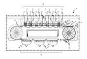
- FIG. 1is a cross-sectional, schematic view of a sheet-fed inkjet marking engine
- FIG. 2is a transverse cross-sectional view of a pneumatic acoustic generator module according to one embodiment of the invention
- FIG. 3is a transverse cross-sectional view of an acoustic air impingement dryer including a pneumatic acoustic generator module according to an embodiment of the invention
- FIG. 4is a cross-sectional schematic view of a portion of the ink printing zone in the inkjet printer of FIG. 1 showing the location of the inkjet printheads and the acoustic air impingement dryers according to an embodiment of the invention
- FIG. 5is a bottom view of an acoustic air impingement dryer illustrating the associated airflow according to an embodiment of the invention
- FIG. 6is a schematic drawing of an airflow control system for controlling an acoustic air impingement dryer according to an alternate embodiment
- FIG. 7is a bottom view of a double-linear-slot acoustic air impingement dryer according to an embodiment of the present invention.
- FIG. 8is a bottom view of an acoustic air impingement dryer having an array of seventeen angled exit slots according to an alternate embodiment
- FIG. 9Ais a bottom view of an acoustic air impingement dryer having an array of seventeen angled protruding exit slots according to an alternate embodiment
- FIG. 9Bis a cross-sectional transverse view of two pneumatic acoustic generators for the acoustic air impingement dryer of FIG. 9A .
- FIG. 10Ais a bottom view of an acoustic air impingement dryer having an array of seventeen angled exit slots with interspersed exhaust air channels according to an alternate embodiment
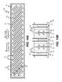
- FIG. 10Bis a cross-sectional transverse view of two pneumatic acoustic generators for the acoustic air impingement dryer of FIG. 10A .
- the present inventionwill be directed in particular to elements forming part of, or in cooperation more directly with the apparatus in accordance with the present invention. It is to be understood that elements not specifically shown or described may take various forms well known to those skilled in the art.
- FIG. 1shows a sheet-fed inkjet printer 10 including seven inkjet printhead modules 11 arranged in an ink printing zone 18 , wherein each inkjet printhead module 11 contains two inkjet printheads 40 , each having an array of ink nozzles for printing drops of ink onto an ink receiver medium 15 .
- Acoustic air impingement dryers 20are positioned downstream of each inkjet printhead module 11 .
- Sheets of ink receiver media 15are fed into contact with transport web 12 by sheet feed device 13 , and the sheets of ink receiver media 15 are electrostatically tacked down to the transport web 12 by corona discharge from a tackdown charger 14 .
- Transport web 12which is rotating in a counterclockwise direction in this example, then transports the sheets of ink receiver media 15 through the ink printing zone 18 such that a multi-color image is formed on the ink receiver medium 15 .
- the inkjet printheads 40would typically print inks that contain dye or pigment of the subtractive primary colors cyan, magenta, yellow, and black and produce typical optical densities such that the image would have a transmission density in the primarily absorbed light color, as measured using a device such as an X-Rite Densitometer with Status A filters of between 0.6 and 1.0.
- Acoustic air impingement dryers 20are placed immediately downstream of each inkjet printhead module 11 so that image defects are not generated because of a buildup of liquid ink on the receiver sheet to the point that the ink starts to coalesce and bead up on the surface of the receiver. Poor print quality characteristics can occur if too much ink is delivered to an area of the receiver surface such that a large amount of liquid is on the surface. Controlling coalescence by immediate drying rather than relying on media coatings or the control of other media and/or ink properties allows for more latitude in the selection of the ink receiver medium. It is not necessary for the acoustic air impingement dryer to completely dry the ink deposit. It is only necessary for the dryer to remove enough of the liquid to avoid image quality artifacts.
- the ink receiver medium 15continues to be transported on the transport web 12 to a final drying zone 17 where any of a number of drying technologies could be used to more fully dry the ink deposit.
- conventional air impingement dryers 16are used to provide final drying.
- the sheetcan be returned to the ink printing zone 18 by transport web 12 for additional printing on the first side in register with the already printed image, the sheet can be removed from the web and delivered as printed product, or the sheet can be sent through a turn-around mechanism (not shown), reintroduced to the transport web 12 at the sheet feed device 13 , and printed on the second side.
- a compact dryer designIn order to produce a high speed inkjet printer in a compact configuration, a compact dryer design must be provided so that the dryers can be placed in proximity to the inkjet printhead modules 11 .
- Acoustic air impingement dryers 20provide a compact design that can sufficiently dry the ink deposits between inkjet printhead modules 11 to prevent the image quality artifacts associated with ink coalescence.
- FIG. 2is a transverse cross-sectional drawing of an exemplary embodiment of a pneumatic acoustic generator module 29 that can be incorporated into an acoustic air impingement dryer 20 ( FIG. 1 ).
- Heated airis supplied to a supply air chamber 22 enclosed within a supply air chamber enclosure 31 via supply air duct 24 and enters acoustic resonant chamber 60 by passing through main air channel inlet slot 61 .
- the acoustic resonant chamber 60comprises the air channels outlined by the dotted rectangle in the figure, and includes the main air channel inlet slot 61 , a main air channel 26 , a main air channel exit slot 51 , and closed-end resonant chambers 43 .
- the main air channel 26is the space formed between two pneumatic acoustic generator halves 25 A and 25 B.
- the closed-end resonant chambers 43are cavities formed in the two pneumatic acoustic generator halves 25 A and 25 B.
- the standing acoustic waves in each closed-end resonant chamber 43combine to generate high acoustic energy levels (i.e., sound levels) in the air flowing through the main air channel 26 .
- the airflow that exits through the main air channel exit slot 51 and impinges on the ink and ink receiver medium 15 ( FIG. 1 )accelerates drying by providing heat, a means of removing evaporated solvent (water), and disruption of the boundary layer formed at the liquid-to-gas phase interface. This boundary layer disruption is provided by the high levels of acoustic pressure in the air stream.
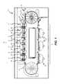
- FIG. 3A transverse cross sectional drawing of an exemplary embodiment of an acoustic air impingement dryer 20 including a pneumatic acoustic generator module 29 is shown in FIG. 3 .
- Airwhich may be heated, is supplied to the pneumatic acoustic generator module 29 via supply air duct 24 into supply air chamber 22 enclosed by supply air chamber enclosure 31 , and exits the pneumatic acoustic generator module 29 through the main air channel 26 as impingement air stream 27 .
- the main air channel 26is formed between the pneumatic acoustic generator halves 25 A and 25 B.
- Closed-end resonant chambers 43are formed into the pneumatic acoustic generator halves 25 A and 25 B and function to generate the acoustic energy that is imparted to the impingement air stream 27 as it passes through the main air channel 26 .
- the impingement air stream 27exits the acoustic air impingement dryer 20 through the main air channel 26 and strikes the sheet of ink receiver medium 15 being transported by transport web 12 in an air impingement drying zone 35 .
- the transport web 12 and the ink receiver medium 15are supported by backup roller 30 in the air impingement drying zone 35 .
- the ink receiver medium 15has an image-wise ink deposit 44 on its surface supplied by the upstream inkjet printhead modules 11 and is being transported though the ink printing zone 18 ( FIG. 1 ) by the transport web 12 .
- the drying and reduction in water volume provided by impingement air stream 27is illustrated by the partially-dried ink deposit 45 , which is shown exiting the acoustic air impingement dryer 20 on the downstream side.
- the impingement air stream 27After striking the ink receiver medium 15 and ink deposit 44 , the impingement air stream 27 contains water vapor as a result of the partial removal of water during the drying of ink deposit 44 . At least some of the impingement air stream 27 follows the path indicated by exhaust air streams 28 through exhaust air channels 33 provided on both sides of the pneumatic acoustic generator module 29 and flows into exhaust air chamber 21 enclosed by exhaust air chamber enclosure 32 . The air then exits the acoustic air impingement dryer 20 through exhaust air duct 23 . Any of the moisture-laden impingement air stream 27 which does not follow the exhaust air stream 28 path into the exhaust air chamber 21 will escape from the acoustic air impingement dryer 20 as shown by escaping air 46 .
- FIG. 4shows a segment of the ink printing zone 18 of inkjet printer 10 ( FIG. 1 ) that includes three inkjet printing modules 11 , each having two inkjet printheads 40 , and two acoustic air impingement dryers 20 . These components are in close proximity to each other to limit the size of the inkjet printer 10 . In many cases, the distance between the main air channel exit slot 51 ( FIG. 2 ) of the acoustic air impingement dryers 20 and the ink nozzles in the nearest inkjet printhead 40 will be 45 mm or less, with the gap between the outer surfaces of the acoustic air impingement dryers 20 and the inkjet printheads 40 being a few millimeters or less.
- the air supplied to acoustic air impingement dryers 20is heated to accelerate the drying process, and this heated air will heat the walls of the exhaust air chamber enclosure 32 .
- inkjet printhead enclosures 41 enclosing the inkjet printheads 40will not be subjected to a significant flow of heated air, and furthermore it is common to control the temperature of the ink in inkjet printheads 40 .
- any moisture laden impingement air that escapes from the acoustic air impingement dryers 20will cool when it comes in contact with the relatively cool inkjet printhead enclosures 41 and lead to the collection of condensation in the possible condensation formation regions 42 . Condensation dripping onto the ink deposit 44 ( FIG. 3 ) or the ink receiver medium 15 ( FIG. 3 ) will lead to unacceptable image quality defects.
- condensationcan be substantially prevented by controlling the flow of air through the drying system such that the moisture laden air is captured within the acoustic air impingement dryers 20 and is removed from the ink printing zone 18 .
- the inventionprevents condensation and condensation-related image quality defects by containing all of the moisture laden air from the acoustic air impingement dryers 20 and removing it from proximity to any possible condensation formation regions 42 within or in proximity to the ink printing zone 18 .
- FIG. 5shows a bottom view of an acoustic air impingement dryer 20 where the supply and exhaust air flows can be adjusted and controlled such that the moisture laden impingement air does not escape from the drying system.
- the impingement air streamexits the main air channel exit slot 51 between the pneumatic acoustic generator halves 25 A and 25 B, it contacts the ink receiver medium in air impingement drying zone 35 and becomes exhaust air stream 28 represented by the dashed arrows in FIG. 5 .
- exhaust air channel 33surrounds the main air channel exit slot 51 on all four sides and receives the exhaust air stream 28 and directs it into the exhaust air duct 23 .
- the airflow in the exhaust air channel 33 between the supply air chamber enclosure 31 and the exhaust air chamber enclosure 32is adjusted and controlled such that the airflow in exhaust air duct 23 is at least as large as the airflow in the supply air duct 24 .
- One advantage to the configuration of FIG. 5is that the air path length that the exhaust air stream 28 must travel from the main air channel exit slot 51 to the exhaust air channel 33 can be made small in order to minimize the chances for condensation on components of the acoustic air impingement dryer 20 (e.g., on the outer surfaces of the pneumatic acoustic generator halves 25 A and 25 B).
- the airflow in the exhaust air duct 23is sufficiently larger than the airflow in the supply air duct 24 that a small amount of air from outside the acoustic air impingement dryer 20 is drawn into the exhaust air channel 33 as represented by the dotted arrows of external air stream 34 . If the acoustic air impingement dryer 20 is operated in this condition, most or all of the moisture laden air in the exhaust air stream 28 will be captured and drawn into the exhaust air channel, and will not escape into the possible condensation formation region 42 ( FIG. 4 ) where it could produce condensation in proximity to the ink printing zone 18 .
- FIG. 6shows a schematic drawing of an airflow control system 56 that can be used to prevent condensation-related artifacts in an inkjet printer 10 ( FIG. 1 ) using acoustic air impingement dryers 20 .
- the impingement air stream 27 ( FIG. 3 ) that enters the air impingement drying zone 35 ( FIG. 3 ) by exiting the acoustic air impingement dryer 20 through main air channel exit slot 51is provided by a supply blower 52 A.
- a supply flow rate of the supply air stream 57is sensed by a supply airflow transducer 50 A.
- the supply air stream 57then passes through heater 55 and travels to the supply air chamber 22 through the supply air duct 24 .
- Exhaust airis collected in exhaust air chamber 21 and exits the acoustic air impingement dryer 20 through the exhaust air duct 23 as exhaust air stream 58 .
- Airflow through the exhaust air stream 58is generated by exhaust blower 52 B and an exhaust flow rate is sensed by an exhaust airflow transducer 50 B.
- the supply flow rate and the exhaust flow rateprovide an indication of the amount of air per unit of time passing through the corresponding duct in comparable units.
- the supply flow rate and the exhaust flow rateare provided as mass flow rates (e.g., in units of grams of air per second).
- the supply airflow transducer 50 A and the exhaust airflow transducer 50 Bmeasure the airflow in some other units (e.g., air velocity), and the sensed quantities are converted to mass flow rates using appropriate transformations known to those skilled in the art.
- Supply flow rate signal 62 A and exhaust flow rate signal 62 B that represent the sensed supply and exhaust airflow ratesare provided to blower controller 54 by the supply airflow transducer 50 A and the exhaust airflow transducer 50 B, respectively.
- Supply blower control signal 63 A and Exhaust blower control signal 63 Bare determined by the blower controller 54 in response to the supply flow rate signal 62 A and the exhaust flow rate signal 62 B are provided to the supply blower 52 A and the exhaust blower 52 B, respectively.
- the supply blower control signal 63 Acontrols the supply blower 52 A
- the exhaust blower control signal 63 Bcontrols the exhaust blower 52 B, such that the impingement air stream 27 ( FIG.
- substantially equal flow ratesshould be interpreted to mean that the flow rates match to within 1%.
- an aim supply flow rate (V s,a ) for the impingement air stream 27is determined experimentally by adjusting the supply flow rate until adequate drying is observed for images being printed by the inkjet printer 10 ( FIG. 1 ).
- the necessary flow ratewill be a function of how much ink is being printed onto the ink receiver medium 15 , so this experiment is preferably performed while the inkjet printer 10 is printing images having the highest expected ink lay down.
- the aim supply flow ratemay be constrained to fall within a particular range to excite the acoustic resonant chamber into resonance.
- the blower controller 54then controls the supply blower 52 A by using a feedback control process to adjust the supply blower control signal 63 A when a difference between the supply flow rate V s sensed by the supply airflow transducer 50 A differs from the aim supply flow rate V s,a by more than a predefined threshold T s (i.e.,
- T sa predefined threshold
- an aim exhaust flow rate V e,ais defined which is greater than or equal to the aim supply flow rate V s,a .
- the aim exhaust flow rate V e,ais set to be equal to the aim supply flow rate V s,a .
- the blower controller 54controls the exhaust blower 52 B by sensing the supply flow rate and the exhaust flow rate, and using a feedback control process to adjust the exhaust blower control signal 63 B when a difference between the exhaust flow rate V e sensed by the exhaust airflow transducer 50 B differs from the supply flow rate V s sensed by the supply airflow transducer 50 A by more than a predefined threshold T d (i.e.,
- the blower controller 54then controls the exhaust blower 52 B by using a feedback control process to adjust the exhaust blower control signal 63 B when a difference between the exhaust flow rate V e sensed by the exhaust airflow transducer 50 B differs from the aim exhaust flow rate V e,a by more than a predefined threshold T e (i.e.,
- one or more inter-component airflow transducers 50 Ccan optionally be provided in the possible condensation formation regions 42 between the acoustic air impingement dryers 20 and the inkjet printhead modules 11 .
- the inter-component airflow transducers 50 Care adapted to measure the magnitude and direction of an inter-component flow rate V i in the possible condensation formation regions 42 . If the supply flow rate V s and the exhaust flow rate V e are properly balanced, then any airflow in possible condensation formation regions 42 should be small and should be in a direction toward the air impingement drying zone 35 ( FIG. 3 ) (i.e., V i ⁇ 0).
- the blower controller 54controls the exhaust blower 52 B by sensing the inter-component flow rate V i , and using a feedback control process to adjust the exhaust blower control signal 63 B when the sensed inter-component flow rate indicates that air is escaping from the air impingement drying zone 35 (i.e., V i >0).
- Linear cross-track slotsare typically used for acoustic air impingement drying. This creates a very small active drying zone if there is only one air impingement slot.
- a larger active drying zonecan be provided using a multiple slot configuration as shown in FIG. 7 , which is a bottom view of a double-linear-slot acoustic air impingement dryer 70 .
- the impingement airexits the two main air channel exit slots 51 that span the entire printing width of the inkjet printer 10 ( FIG. 1 ) and are perpendicular to the process direction (i.e., the direction that the ink receiver medium 15 ( FIG.
- FIG. 7 configurationis not optimal for spent air control and drying uniformity due to the fact that the impingement air does not have a short and direct path to the exhaust air channel 33 in the exhaust air interference zone 71 , which is the central area enclosed by the dashed boundary in FIG. 7 .
- the impingement air from both main air channel exit slots 51is trying to flow through the same region and must exit the exhaust air interference zone 71 at one of the ends of this region, which are in proximity to exhaust air channel 33 .
- the differences in air path length for several locations along one of the two main air channel exit slots 51are illustrated by the air flow paths 72 (shown as dotted arrows). The differences in air path length will cause different air flow rates, and consequently different drying rates along the length of the acoustic air impingement dryer 70 .
- main air channel exit slots 51that span the entire printing width if the inkjet printer 10 ( FIG. 1 ) is holding consistent slot dimensions along the entire length of the slots. If the slot dimensions vary by ⁇ 250 microns, the output acoustic frequency can change by 10 to 20 kHz. When that happens, the ink receiving medium drying location (i.e., the distance from the main air channel exit slot to the ink receiving medium that leads to maximum drying) changes accordingly; this leads to a non-uniform drying rate along the length of the acoustic air impingement dryer.
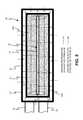
- FIG. 8shows a bottom view of one such acoustic air impingement dryer 80 having an array of seventeen angled main air channel exit slots 51 formed into a baseplate 94 .
- Each of the main air channel exit slots 51is oriented at an oblique angle relative to the cross-track (width) dimension of the acoustic air impingement dryer 80 , and also relative to the process direction.
- Each of the main air channel exit slots 51will be associated with a corresponding acoustic resonant chamber (not shown in FIG. 8 ) having an inlet slot which receives air from the inlet chamber.
- One or more peripheral exhaust air channels 33can be arranged around the outer boundary of the baseplate 94 for removing the air directed onto the ink receiver medium 15 ( FIG. 1 ) by the main air channel exit slots 51 .
- the baseplate 94is surrounded on all four sides by a single continuous exhaust air channel 33 .
- individual exhaust air channels 33may be provided on some or all of the sides of the baseplate 94 .
- FIG. 8has the advantage that there is a much smaller variation in the air path length from the main air channel exit slots 51 to the exhaust air channel 33 relative to the double-linear-slot acoustic air impingement dryer 70 shown in FIG. 7 .
- the smaller variation in air flow path lengthleads to more uniform impingement air flow, and more uniform drying.
- the ability to maintain slot dimensions in the shorter main air channel exit slots 51 of the acoustic air impingement dryer 80is an additional benefit of this configuration.
- FIG. 8Another advantage to the configuration of FIG. 8 is that the length of the longest air path length that the air must travel from the main air channel exit slots 51 to the exhaust air channel 33 is significantly smaller than for the configuration of FIG. 7 . This reduces the chances for condensation on the baseplate 94 .
- the region of the baseplate 94 including the main air channel exit slots 51defines a drying zone 82 (shown with a dashed boundary) within which air impinges onto the ink receiver medium 15 .
- the dotted lines in FIG. 8indicate the boundaries of each of sixteen double pass drying zone portions 81 that are formed under the acoustic air impingement dryer 80 .
- each point on the ink receiver medium 15is exposed to two impingement air streams for both the angled-slot acoustic air impingement dryer 80 shown in FIG. 8 and the double-linear-slot acoustic air impingement dryer 70 shown in FIG. 7 , but the acoustic air impingement dryer 80 has the advantage of more uniform drying characteristics. It will be obvious to one skilled in the art that the number of impingement air streams to which a point on the ink receiver medium 15 is exposed can be adjusted by controlling the oblique angle of the main air channel exit slots 51 .
- FIG. 9Ashows a bottom view of an acoustic air impingement dryer 90 that has main air channel exit slots 51 formed in protruding exit slot nozzles 93 that protrude from the baseplate 94 .
- the region of the baseplate 94 including the main air channel exit slots 51defines a drying zone 82 (shown with a dashed boundary) within which air impinges onto the ink receiver medium 15 .
- the main air channel exit slots 51are arranged at an oblique angle relative to the cross-track (width) dimension of the acoustic air impingement dryer 90 , and also relative to the process direction as in the acoustic air impingement dryer 80 FIG. 8 .
- protruding exit slot nozzles 93form return flow channels 92 between the main air channel exit slots 51 . Having the protruding exit slot nozzles 93 protrude down from the baseplate 94 with a gap between them provides well-defined air flow paths 97 (shown with dotted arrows) for the impingement air to travel from the main air channel exit slots 51 to the exhaust air channel 33 that encompasses the exterior boundary of the nozzle array, thereby improving air flow and drying uniformity.
- an air barrier 96is formed around the exhaust air channel 33 to block air from passing out of the drying zone 82 into other areas of the inkjet printer 10 ( FIG. 1 ).
- the air barrier 96can be, for example, a protruding lip similar to the protruding exit slot nozzles 93 which provides a smaller gap between the air barrier 96 and the ink receiver medium 15 relative to the gap between the baseplate 94 and the ink receiver medium 15 .
- the air barrier 96fully surrounds the exhaust air channel 33 , which in turn fully surrounds the drying zone 82 .
- air barriers 96may only be provided around a portion of the drying zone 82 .
- FIG. 9Bshows a cross-sectional transverse view of two pneumatic acoustic generators 95 from the acoustic air impingement dryer 90 in FIG. 9A .
- the cross-sectionis at a 45 degree angle to the cross-track (width) dimension and the process direction.
- the acoustic resonant chambers 60now include the additional air flow path provided by protruding exit slot nozzles 93 which extend below the baseplate 94 .
- each point on the ink receiving sheetis exposed to the impingement air stream of two protruding exit slots.
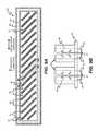
- FIG. 10Ais a bottom view of an acoustic air impingement dryer 98 having an array of seventeen angled main air channel exit slots 51 arranged in drying zone 82 with interspersed exhaust air channels 33 according to an alternate embodiment.
- the exhaust air channels 33are formed as slots in the baseplate 94 that are positioned between each of the main air channel exit slots 51 .
- the air flow paths 97have a consistent and short path length from the main air channel exit slots 51 to the exhaust air channels 33 .
- an air barrier 96is provided surrounding the drying zone 82 to further limit the escaping of air from the acoustic air impingement dryer 98 into other portions of the inkjet printer 10 .
- exhaust air channels 33can also be provided surrounding one or more sides of the drying zone 82 as in FIG. 9A to provide additional protection against escaping air.
- FIG. 10AAnother advantage to the configuration of FIG. 10A is that the length of the longest air path length that the air must travel from the main air channel exit slots 51 to the exhaust air channel 33 is even smaller than that in the FIG. 8 and FIG. 9A configurations. This further reduces the chances for condensation on the baseplate 94 .
- FIG. 10Bshows a cross-sectional transverse view of two pneumatic acoustic generators 95 from the acoustic air impingement dryer 98 in FIG. 10A .
- the cross-sectionis at a 45 degree angle to the cross-track (width) dimension and the process direction.
- the impinging air from the main air channel exit slots 51follows the indicated air flow paths 97 to exit through one of the nearby exhaust air channels 33 .
- a further advantage of the angled slot configurations of FIGS. 8 , 9 A and 10 Ais that the airflow to individual main air channel exit slots 51 can be turned on or off in accordance with the width of the ink receiver medium 15 that is being dried. For wide media air can be supplied to all of the main air channel exit slots 51 , and for narrower media air can be supplied to only a subset of the main air channel exit slots 51 that are positioned over the ink receiver medium 15 .
- FIG. 6it will be obvious to one skilled in the art that the airflow control system described relative to FIG. 6 can be applied to any of the alternate configurations shown in FIGS. 7 , 8 , 9 A-B, and 10 A-B.
- all of the main air channel exit slots 51will be fed from a single airflow source being controlled to provide a supply air stream 57 ( FIG. 6 ) at an appropriate supply flow rate.
- all of the exhaust air channels 33will feed into a single exhaust air stream 58 ( FIG. 6 ) being controlled to provide an appropriate exhaust flow rate.
- proper control of the supply flow rate and the exhaust flow ratecan be used to prevent impinging air from escaping into other areas of the inkjet printer 10 ( FIG. 1 ).
Landscapes
- Engineering & Computer Science (AREA)
- Mechanical Engineering (AREA)
- General Engineering & Computer Science (AREA)
- Ink Jet (AREA)
Abstract
Description
- an inlet chamber that receives air from the airflow source
- a plurality of acoustic resonant chambers, each having an inlet slot that receives air from the inlet chamber and an outlet slot that directs air onto the material, wherein the acoustic resonant chambers impart acoustic energy to the transiting air, the outlet slots being oriented at an oblique angle relative to the width dimension of the pneumatic transducer unit; and
- a plurality of exhaust air channels interspersed between the outlet slots for removing the air directed onto the material by the acoustic resonant chambers; and
Ve,a=Vs,a+ΔV (1)
where ΔVais an aim flow rate difference, which is a predefined non-negative constant. In some embodiments, the aim flow rate difference ΔV is set to a percentage of the aim supply flow rate Vs,a(e.g., ΔVa=0.02×Vs,a). The blower controller54 then controls the
- 10 inkjet printer
- 11 inkjet printhead module
- 12 transport web
- 13 sheet feed device
- 14 tackdown charger
- 15 ink receiver medium
- 16 air impingement dryer
- 17 final drying zone
- 18 ink printing zone
- 20 acoustic air impingement dryer
- 21 exhaust air chamber
- 22 supply air chamber
- 23 exhaust air duct
- 24 supply air duct
- 25A pneumatic acoustic generator half
- 25B pneumatic acoustic generator half
- 26 main air channel
- 27 impingement air stream
- 28 exhaust air stream
- 29 pneumatic acoustic generator module
- 30 backup roller
- 31 supply air chamber enclosure
- 32 exhaust air chamber enclosure
- 33 exhaust air channel
- 34 external air stream
- 35 air impingement drying zone
- 40 inkjet printhead
- 41 inkjet printhead enclosure
- 42 possible condensation formation region
- 43 closed-end resonant chambers
- 44 ink deposit
- 45 partially dried ink deposit
- 46 escaping air
- 50A supply airflow transducer
- 50B exhaust airflow transducer
- 50C inter-component airflow transducer
- 51 main air channel exit slot
- 52A supply blower
- 52B exhaust blower
- 54 blower controller
- 55 heater
- 56 airflow control system
- 57 supply air stream
- 58 exhaust air stream
- 60 acoustic resonant chamber
- 61 main air channel inlet slot
- 62A supply flow rate signal
- 62B exhaust flow rate signal
- 63A supply blower control signal
- 63B exhaust blower control signal
- 70 acoustic air impingement dryer
- 71 exhaust air interference zone
- 72 air flow paths
- 80 acoustic air impingement dryer
- 81 double pass drying zone portions
- 82 drying zone
- 90 acoustic air impingement dryer
- 92 return flow channel
- 93 protruding exit slot nozzles
- 94 baseplate
- 95 pneumatic acoustic generator
- 96 air barrier
- 97 air flow paths
- 98 acoustic air impingement dryer
Claims (12)
Priority Applications (1)
| Application Number | Priority Date | Filing Date | Title |
|---|---|---|---|
| US13/693,344US9127884B2 (en) | 2012-12-04 | 2012-12-04 | Acoustic drying system with interspersed exhaust channels |
Applications Claiming Priority (1)
| Application Number | Priority Date | Filing Date | Title |
|---|---|---|---|
| US13/693,344US9127884B2 (en) | 2012-12-04 | 2012-12-04 | Acoustic drying system with interspersed exhaust channels |
Publications (2)
| Publication Number | Publication Date |
|---|---|
| US20140150284A1 US20140150284A1 (en) | 2014-06-05 |
| US9127884B2true US9127884B2 (en) | 2015-09-08 |
Family
ID=50824012
Family Applications (1)
| Application Number | Title | Priority Date | Filing Date |
|---|---|---|---|
| US13/693,344Expired - Fee RelatedUS9127884B2 (en) | 2012-12-04 | 2012-12-04 | Acoustic drying system with interspersed exhaust channels |
Country Status (1)
| Country | Link |
|---|---|
| US (1) | US9127884B2 (en) |
Cited By (2)
| Publication number | Priority date | Publication date | Assignee | Title |
|---|---|---|---|---|
| US20180209088A1 (en)* | 2015-05-21 | 2018-07-26 | Lavatec Laundry Technology Gmbh | Modular air drier |
| US12013181B2 (en)* | 2020-06-03 | 2024-06-18 | Toyota Jidosha Kabushiki Kaisha | Electrode sheet drying apparatus |
Families Citing this family (5)
| Publication number | Priority date | Publication date | Assignee | Title |
|---|---|---|---|---|
| US20140150285A1 (en)* | 2012-12-04 | 2014-06-05 | Rodney Ray Bucks | Acoustic drying system with peripheral exhaust channel |
| US9127884B2 (en)* | 2012-12-04 | 2015-09-08 | Eastman Kodak Company | Acoustic drying system with interspersed exhaust channels |
| CN105953549A (en)* | 2016-06-23 | 2016-09-21 | 江门市合益印刷有限公司 | Crawler-type paperboard dryer |
| JP7706972B2 (en)* | 2021-07-29 | 2025-07-14 | キヤノン株式会社 | Recording device |
| EP4467346A1 (en)* | 2023-05-24 | 2024-11-27 | Canon Kabushiki Kaisha | Drying device |
Citations (33)
| Publication number | Priority date | Publication date | Assignee | Title |
|---|---|---|---|---|
| US3694926A (en)* | 1969-07-07 | 1972-10-03 | Dominion Eng Works Ltd | Sonic drying of webs |
| US3750306A (en)* | 1969-11-07 | 1973-08-07 | Dominion Eng Works Ltd | Sonic drying of webs on rolls |
| JPH0755338A (en) | 1993-08-19 | 1995-03-03 | Shinko:Kk | Drying device of running member |
| US6325475B1 (en)* | 1996-09-06 | 2001-12-04 | Microfab Technologies Inc. | Devices for presenting airborne materials to the nose |
| US6340225B1 (en)* | 1999-01-19 | 2002-01-22 | Xerox Corporation | Cross flow air system for ink jet printer |
| US6393719B1 (en) | 1998-07-01 | 2002-05-28 | The Procter & Gamble Company | Process and apparatus for removing water from fibrous web using oscillatory flow-reversing air or gas |
| US6431702B2 (en) | 1999-06-08 | 2002-08-13 | Hewlett-Packard Company | Apparatus and method using ultrasonic energy to fix ink to print media |
| US20030184630A1 (en) | 2002-03-29 | 2003-10-02 | Elgee Steven B. | Drying station |
| US6754457B2 (en) | 2001-04-06 | 2004-06-22 | Nexpress Solutions Llc | Pre-heater for an electrostatographic reproduction apparatus fusing assembly |
| US6766593B2 (en)* | 2001-03-27 | 2004-07-27 | Leica Microsystems Nussloch Gmbh | Device for drying solvent-based ink |
| US6920704B1 (en)* | 2004-01-21 | 2005-07-26 | Silverbrook Research Pty Ltd | Drying method for a printer |
| US6954994B1 (en)* | 2004-06-30 | 2005-10-18 | Hewlett-Packard Development Company, L.P. | Moisture removal mechanism |
| US7080465B2 (en)* | 2003-03-07 | 2006-07-25 | Fuji Photo Film Co., Ltd. | Method of manufacturing inkjet recording sheet and drying apparatus for application film |
| US20060260642A1 (en)* | 2000-06-26 | 2006-11-23 | Steven Verhaverbeke | Method and apparatus for wafer cleaning |
| US7334348B2 (en)* | 2003-09-08 | 2008-02-26 | Shima Seiki Mfg., Ltd. | Dryer apparatus for clothing knitted or woven fabric |
| US7424781B2 (en)* | 2004-01-08 | 2008-09-16 | Eastman Kodak Company | Media drying system and method |
| US7451774B2 (en)* | 2000-06-26 | 2008-11-18 | Applied Materials, Inc. | Method and apparatus for wafer cleaning |
| US20090200398A1 (en)* | 2008-02-13 | 2009-08-13 | L'oreal | Spray head including a sonotrode with a composition feed channel passing therethrough |
| US20090200392A1 (en)* | 2008-02-13 | 2009-08-13 | L'oreal | Device for spraying a cosmetic composition while blowing hot or cold air |
| US20100199510A1 (en)* | 2009-02-09 | 2010-08-12 | Zinovy Plavnik | Ultrasonic drying system and method |
| US7934791B2 (en)* | 2004-12-22 | 2011-05-03 | Canon Kabushiki Kaisha | Printing apparatus, ink mist collecting method, and printing method |
| US20110114744A1 (en)* | 2005-08-26 | 2011-05-19 | Ricciardi Jonathan J | Method and Apparatus for an Improved Aerosol Generator and Associated Uses and Equipment |
| US7966743B2 (en)* | 2007-07-31 | 2011-06-28 | Eastman Kodak Company | Micro-structured drying for inkjet printers |
| US20120192861A1 (en)* | 2011-01-31 | 2012-08-02 | Genoa Pharmaceuticals, Inc. | Aerosol pirfenidone and pyridone analog compounds and uses thereof |
| US20120291989A1 (en)* | 2009-06-29 | 2012-11-22 | Lightsail Energy Inc. | Compressed air energy storage system utilizing two-phase flow to facilitate heat exchange |
| US8322047B2 (en)* | 2007-06-29 | 2012-12-04 | Moore Wallace North America, Inc. | System and method for drying a freshly printed medium |
| US8347525B2 (en)* | 2007-09-24 | 2013-01-08 | Inhalation Sciences Sweden Ab | System and method for producing dry formulations |
| US8690292B1 (en)* | 2012-12-20 | 2014-04-08 | Eastman Kodak Company | Condensation control method using surface energy management |
| US20140150285A1 (en)* | 2012-12-04 | 2014-06-05 | Rodney Ray Bucks | Acoustic drying system with peripheral exhaust channel |
| US20140152750A1 (en)* | 2012-12-04 | 2014-06-05 | James Douglas Shifley | Acoustic drying system with matched exhaust flow |
| US20140150284A1 (en)* | 2012-12-04 | 2014-06-05 | Andrew Ciaschi | Acoustic drying system with interspersed exhaust channels |
| US20140202024A1 (en)* | 2013-01-18 | 2014-07-24 | Rodney Ray Bucks | Acoustic wave drying method |
| US20140234949A1 (en)* | 2011-09-25 | 2014-08-21 | Theranos, Inc. | Systems and methods for fluid and component handling |
- 2012
- 2012-12-04USUS13/693,344patent/US9127884B2/ennot_activeExpired - Fee Related
Patent Citations (36)
| Publication number | Priority date | Publication date | Assignee | Title |
|---|---|---|---|---|
| US3694926A (en)* | 1969-07-07 | 1972-10-03 | Dominion Eng Works Ltd | Sonic drying of webs |
| US3750306A (en)* | 1969-11-07 | 1973-08-07 | Dominion Eng Works Ltd | Sonic drying of webs on rolls |
| JPH0755338A (en) | 1993-08-19 | 1995-03-03 | Shinko:Kk | Drying device of running member |
| US6325475B1 (en)* | 1996-09-06 | 2001-12-04 | Microfab Technologies Inc. | Devices for presenting airborne materials to the nose |
| US6393719B1 (en) | 1998-07-01 | 2002-05-28 | The Procter & Gamble Company | Process and apparatus for removing water from fibrous web using oscillatory flow-reversing air or gas |
| US6340225B1 (en)* | 1999-01-19 | 2002-01-22 | Xerox Corporation | Cross flow air system for ink jet printer |
| US6431702B2 (en) | 1999-06-08 | 2002-08-13 | Hewlett-Packard Company | Apparatus and method using ultrasonic energy to fix ink to print media |
| US7334588B2 (en)* | 2000-06-26 | 2008-02-26 | Applied Materials, Inc. | Method and apparatus for wafer cleaning |
| US7451774B2 (en)* | 2000-06-26 | 2008-11-18 | Applied Materials, Inc. | Method and apparatus for wafer cleaning |
| US20060260642A1 (en)* | 2000-06-26 | 2006-11-23 | Steven Verhaverbeke | Method and apparatus for wafer cleaning |
| US6766593B2 (en)* | 2001-03-27 | 2004-07-27 | Leica Microsystems Nussloch Gmbh | Device for drying solvent-based ink |
| US6754457B2 (en) | 2001-04-06 | 2004-06-22 | Nexpress Solutions Llc | Pre-heater for an electrostatographic reproduction apparatus fusing assembly |
| US20030184630A1 (en) | 2002-03-29 | 2003-10-02 | Elgee Steven B. | Drying station |
| US7080465B2 (en)* | 2003-03-07 | 2006-07-25 | Fuji Photo Film Co., Ltd. | Method of manufacturing inkjet recording sheet and drying apparatus for application film |
| US7334348B2 (en)* | 2003-09-08 | 2008-02-26 | Shima Seiki Mfg., Ltd. | Dryer apparatus for clothing knitted or woven fabric |
| US7424781B2 (en)* | 2004-01-08 | 2008-09-16 | Eastman Kodak Company | Media drying system and method |
| US6920704B1 (en)* | 2004-01-21 | 2005-07-26 | Silverbrook Research Pty Ltd | Drying method for a printer |
| US6954994B1 (en)* | 2004-06-30 | 2005-10-18 | Hewlett-Packard Development Company, L.P. | Moisture removal mechanism |
| US7934791B2 (en)* | 2004-12-22 | 2011-05-03 | Canon Kabushiki Kaisha | Printing apparatus, ink mist collecting method, and printing method |
| US20110114744A1 (en)* | 2005-08-26 | 2011-05-19 | Ricciardi Jonathan J | Method and Apparatus for an Improved Aerosol Generator and Associated Uses and Equipment |
| US8322047B2 (en)* | 2007-06-29 | 2012-12-04 | Moore Wallace North America, Inc. | System and method for drying a freshly printed medium |
| US7966743B2 (en)* | 2007-07-31 | 2011-06-28 | Eastman Kodak Company | Micro-structured drying for inkjet printers |
| US8347525B2 (en)* | 2007-09-24 | 2013-01-08 | Inhalation Sciences Sweden Ab | System and method for producing dry formulations |
| US20090200392A1 (en)* | 2008-02-13 | 2009-08-13 | L'oreal | Device for spraying a cosmetic composition while blowing hot or cold air |
| US20090200398A1 (en)* | 2008-02-13 | 2009-08-13 | L'oreal | Spray head including a sonotrode with a composition feed channel passing therethrough |
| US20100199510A1 (en)* | 2009-02-09 | 2010-08-12 | Zinovy Plavnik | Ultrasonic drying system and method |
| US20120291989A1 (en)* | 2009-06-29 | 2012-11-22 | Lightsail Energy Inc. | Compressed air energy storage system utilizing two-phase flow to facilitate heat exchange |
| US20120192861A1 (en)* | 2011-01-31 | 2012-08-02 | Genoa Pharmaceuticals, Inc. | Aerosol pirfenidone and pyridone analog compounds and uses thereof |
| US20140234949A1 (en)* | 2011-09-25 | 2014-08-21 | Theranos, Inc. | Systems and methods for fluid and component handling |
| US20140150285A1 (en)* | 2012-12-04 | 2014-06-05 | Rodney Ray Bucks | Acoustic drying system with peripheral exhaust channel |
| US20140152750A1 (en)* | 2012-12-04 | 2014-06-05 | James Douglas Shifley | Acoustic drying system with matched exhaust flow |
| US20140152749A1 (en)* | 2012-12-04 | 2014-06-05 | James Douglas Shifley | Acoustic drying system with matched exhaust flow |
| US20140150284A1 (en)* | 2012-12-04 | 2014-06-05 | Andrew Ciaschi | Acoustic drying system with interspersed exhaust channels |
| US8770738B2 (en)* | 2012-12-04 | 2014-07-08 | Eastman Kodak Company | Acoustic drying system with matched exhaust flow |
| US8690292B1 (en)* | 2012-12-20 | 2014-04-08 | Eastman Kodak Company | Condensation control method using surface energy management |
| US20140202024A1 (en)* | 2013-01-18 | 2014-07-24 | Rodney Ray Bucks | Acoustic wave drying method |
Non-Patent Citations (1)
| Title |
|---|
| Gene, Plavnik, "Innovative drying technology can improve productivity," GravurEzine, pp. 8-12, http://www.gravurexchange.com/articles/heat-technologies.htm, Apr. 2011. |
Cited By (3)
| Publication number | Priority date | Publication date | Assignee | Title |
|---|---|---|---|---|
| US20180209088A1 (en)* | 2015-05-21 | 2018-07-26 | Lavatec Laundry Technology Gmbh | Modular air drier |
| US10612183B2 (en)* | 2015-05-21 | 2020-04-07 | Lavatec Laundry Technology Gmbh | Modular air drier |
| US12013181B2 (en)* | 2020-06-03 | 2024-06-18 | Toyota Jidosha Kabushiki Kaisha | Electrode sheet drying apparatus |
Also Published As
| Publication number | Publication date |
|---|---|
| US20140150284A1 (en) | 2014-06-05 |
Similar Documents
| Publication | Publication Date | Title |
|---|---|---|
| US8931891B2 (en) | Acoustic drying system with matched exhaust flow | |
| US9127884B2 (en) | Acoustic drying system with interspersed exhaust channels | |
| US20140150285A1 (en) | Acoustic drying system with peripheral exhaust channel | |
| US8939545B2 (en) | Inkjet printing with managed airflow for condensation control | |
| US9056496B2 (en) | Recording substrate treatment apparatus, printing system and method of drying | |
| US9073328B2 (en) | Inkjet marking module and method for conditioning inkjet marking module | |
| US8943706B2 (en) | Acoustic wave drying method | |
| JP6709671B2 (en) | System and method for reducing printhead condensation in a print zone in an aqueous inkjet printer | |
| US10144227B2 (en) | Recording substrate treatment apparatus, printing system and method of drying | |
| US20200300542A1 (en) | Method for drying a substrate, dryer module for carrying out the method, and dryer system | |
| US20140176654A1 (en) | Inkjet printing system with condensation control | |
| US9163875B2 (en) | Acoustic drying system with sound outlet channel | |
| US8690292B1 (en) | Condensation control method using surface energy management | |
| US9586403B2 (en) | Ink printing apparatus | |
| US9140494B2 (en) | Acoustic wave drying system | |
| KR101063069B1 (en) | Device for depositing droplets on a substrate | |
| EP3842247B1 (en) | System and method to detect ink drop directionality degradation and perform remedial measures to prevent failing inkjets in printheads | |
| US20140202023A1 (en) | Acoustic drying method using sound outlet channel | |
| US8702228B1 (en) | Inkjet printing system with co-linear airflow management | |
| US8820916B2 (en) | Managing condensation in an inkjet printing system with co-linear airflow |
Legal Events
| Date | Code | Title | Description |
|---|---|---|---|
| AS | Assignment | Owner name:EASTMAN KODAK, NEW YORK Free format text:ASSIGNMENT OF ASSIGNORS INTEREST;ASSIGNORS:CIASCHI, ANDREW;SHIFLEY, JAMES DOUGLAS;BUCKS, RODNEY RAY;AND OTHERS;SIGNING DATES FROM 20121106 TO 20121126;REEL/FRAME:029400/0531 | |
| AS | Assignment | Owner name:WILMINGTON TRUST, NATIONAL ASSOCIATION, AS AGENT, MINNESOTA Free format text:PATENT SECURITY AGREEMENT;ASSIGNORS:EASTMAN KODAK COMPANY;PAKON, INC.;REEL/FRAME:030122/0235 Effective date:20130322 Owner name:WILMINGTON TRUST, NATIONAL ASSOCIATION, AS AGENT, Free format text:PATENT SECURITY AGREEMENT;ASSIGNORS:EASTMAN KODAK COMPANY;PAKON, INC.;REEL/FRAME:030122/0235 Effective date:20130322 | |
| AS | Assignment | Owner name:BANK OF AMERICA N.A., AS AGENT, MASSACHUSETTS Free format text:INTELLECTUAL PROPERTY SECURITY AGREEMENT (ABL);ASSIGNORS:EASTMAN KODAK COMPANY;FAR EAST DEVELOPMENT LTD.;FPC INC.;AND OTHERS;REEL/FRAME:031162/0117 Effective date:20130903 Owner name:JPMORGAN CHASE BANK, N.A., AS ADMINISTRATIVE, DELAWARE Free format text:INTELLECTUAL PROPERTY SECURITY AGREEMENT (FIRST LIEN);ASSIGNORS:EASTMAN KODAK COMPANY;FAR EAST DEVELOPMENT LTD.;FPC INC.;AND OTHERS;REEL/FRAME:031158/0001 Effective date:20130903 Owner name:BARCLAYS BANK PLC, AS ADMINISTRATIVE AGENT, NEW YORK Free format text:INTELLECTUAL PROPERTY SECURITY AGREEMENT (SECOND LIEN);ASSIGNORS:EASTMAN KODAK COMPANY;FAR EAST DEVELOPMENT LTD.;FPC INC.;AND OTHERS;REEL/FRAME:031159/0001 Effective date:20130903 Owner name:JPMORGAN CHASE BANK, N.A., AS ADMINISTRATIVE, DELA Free format text:INTELLECTUAL PROPERTY SECURITY AGREEMENT (FIRST LIEN);ASSIGNORS:EASTMAN KODAK COMPANY;FAR EAST DEVELOPMENT LTD.;FPC INC.;AND OTHERS;REEL/FRAME:031158/0001 Effective date:20130903 Owner name:BARCLAYS BANK PLC, AS ADMINISTRATIVE AGENT, NEW YO Free format text:INTELLECTUAL PROPERTY SECURITY AGREEMENT (SECOND LIEN);ASSIGNORS:EASTMAN KODAK COMPANY;FAR EAST DEVELOPMENT LTD.;FPC INC.;AND OTHERS;REEL/FRAME:031159/0001 Effective date:20130903 Owner name:EASTMAN KODAK COMPANY, NEW YORK Free format text:RELEASE OF SECURITY INTEREST IN PATENTS;ASSIGNORS:CITICORP NORTH AMERICA, INC., AS SENIOR DIP AGENT;WILMINGTON TRUST, NATIONAL ASSOCIATION, AS JUNIOR DIP AGENT;REEL/FRAME:031157/0451 Effective date:20130903 Owner name:PAKON, INC., NEW YORK Free format text:RELEASE OF SECURITY INTEREST IN PATENTS;ASSIGNORS:CITICORP NORTH AMERICA, INC., AS SENIOR DIP AGENT;WILMINGTON TRUST, NATIONAL ASSOCIATION, AS JUNIOR DIP AGENT;REEL/FRAME:031157/0451 Effective date:20130903 | |
| FEPP | Fee payment procedure | Free format text:PAYOR NUMBER ASSIGNED (ORIGINAL EVENT CODE: ASPN); ENTITY STATUS OF PATENT OWNER: LARGE ENTITY | |
| ZAAA | Notice of allowance and fees due | Free format text:ORIGINAL CODE: NOA | |
| ZAAB | Notice of allowance mailed | Free format text:ORIGINAL CODE: MN/=. | |
| STCF | Information on status: patent grant | Free format text:PATENTED CASE | |
| MAFP | Maintenance fee payment | Free format text:PAYMENT OF MAINTENANCE FEE, 4TH YEAR, LARGE ENTITY (ORIGINAL EVENT CODE: M1551); ENTITY STATUS OF PATENT OWNER: LARGE ENTITY Year of fee payment:4 | |
| AS | Assignment | Owner name:LASER PACIFIC MEDIA CORPORATION, NEW YORK Free format text:RELEASE BY SECURED PARTY;ASSIGNOR:JP MORGAN CHASE BANK, N.A., AS ADMINISTRATIVE AGENT;REEL/FRAME:050239/0001 Effective date:20190617 Owner name:KODAK (NEAR EAST), INC., NEW YORK Free format text:RELEASE BY SECURED PARTY;ASSIGNOR:JP MORGAN CHASE BANK, N.A., AS ADMINISTRATIVE AGENT;REEL/FRAME:050239/0001 Effective date:20190617 Owner name:QUALEX, INC., NEW YORK Free format text:RELEASE BY SECURED PARTY;ASSIGNOR:JP MORGAN CHASE BANK, N.A., AS ADMINISTRATIVE AGENT;REEL/FRAME:050239/0001 Effective date:20190617 Owner name:KODAK AVIATION LEASING LLC, NEW YORK Free format text:RELEASE BY SECURED PARTY;ASSIGNOR:JP MORGAN CHASE BANK, N.A., AS ADMINISTRATIVE AGENT;REEL/FRAME:050239/0001 Effective date:20190617 Owner name:KODAK AMERICAS, LTD., NEW YORK Free format text:RELEASE BY SECURED PARTY;ASSIGNOR:JP MORGAN CHASE BANK, N.A., AS ADMINISTRATIVE AGENT;REEL/FRAME:050239/0001 Effective date:20190617 Owner name:KODAK PHILIPPINES, LTD., NEW YORK Free format text:RELEASE BY SECURED PARTY;ASSIGNOR:JP MORGAN CHASE BANK, N.A., AS ADMINISTRATIVE AGENT;REEL/FRAME:050239/0001 Effective date:20190617 Owner name:FPC, INC., NEW YORK Free format text:RELEASE BY SECURED PARTY;ASSIGNOR:JP MORGAN CHASE BANK, N.A., AS ADMINISTRATIVE AGENT;REEL/FRAME:050239/0001 Effective date:20190617 Owner name:KODAK REALTY, INC., NEW YORK Free format text:RELEASE BY SECURED PARTY;ASSIGNOR:JP MORGAN CHASE BANK, N.A., AS ADMINISTRATIVE AGENT;REEL/FRAME:050239/0001 Effective date:20190617 Owner name:KODAK IMAGING NETWORK, INC., NEW YORK Free format text:RELEASE BY SECURED PARTY;ASSIGNOR:JP MORGAN CHASE BANK, N.A., AS ADMINISTRATIVE AGENT;REEL/FRAME:050239/0001 Effective date:20190617 Owner name:EASTMAN KODAK COMPANY, NEW YORK Free format text:RELEASE BY SECURED PARTY;ASSIGNOR:JP MORGAN CHASE BANK, N.A., AS ADMINISTRATIVE AGENT;REEL/FRAME:050239/0001 Effective date:20190617 Owner name:PAKON, INC., NEW YORK Free format text:RELEASE BY SECURED PARTY;ASSIGNOR:JP MORGAN CHASE BANK, N.A., AS ADMINISTRATIVE AGENT;REEL/FRAME:050239/0001 Effective date:20190617 Owner name:FAR EAST DEVELOPMENT LTD., NEW YORK Free format text:RELEASE BY SECURED PARTY;ASSIGNOR:JP MORGAN CHASE BANK, N.A., AS ADMINISTRATIVE AGENT;REEL/FRAME:050239/0001 Effective date:20190617 Owner name:NPEC, INC., NEW YORK Free format text:RELEASE BY SECURED PARTY;ASSIGNOR:JP MORGAN CHASE BANK, N.A., AS ADMINISTRATIVE AGENT;REEL/FRAME:050239/0001 Effective date:20190617 Owner name:KODAK PORTUGUESA LIMITED, NEW YORK Free format text:RELEASE BY SECURED PARTY;ASSIGNOR:JP MORGAN CHASE BANK, N.A., AS ADMINISTRATIVE AGENT;REEL/FRAME:050239/0001 Effective date:20190617 Owner name:CREO MANUFACTURING AMERICA LLC, NEW YORK Free format text:RELEASE BY SECURED PARTY;ASSIGNOR:JP MORGAN CHASE BANK, N.A., AS ADMINISTRATIVE AGENT;REEL/FRAME:050239/0001 Effective date:20190617 | |
| AS | Assignment | Owner name:KODAK AMERICAS, LTD., NEW YORK Free format text:RELEASE BY SECURED PARTY;ASSIGNOR:JP MORGAN CHASE BANK, N.A., AS ADMINISTRATIVE AGENT;REEL/FRAME:049901/0001 Effective date:20190617 Owner name:KODAK AVIATION LEASING LLC, NEW YORK Free format text:RELEASE BY SECURED PARTY;ASSIGNOR:JP MORGAN CHASE BANK, N.A., AS ADMINISTRATIVE AGENT;REEL/FRAME:049901/0001 Effective date:20190617 Owner name:CREO MANUFACTURING AMERICA LLC, NEW YORK Free format text:RELEASE BY SECURED PARTY;ASSIGNOR:JP MORGAN CHASE BANK, N.A., AS ADMINISTRATIVE AGENT;REEL/FRAME:049901/0001 Effective date:20190617 Owner name:KODAK PORTUGUESA LIMITED, NEW YORK Free format text:RELEASE BY SECURED PARTY;ASSIGNOR:JP MORGAN CHASE BANK, N.A., AS ADMINISTRATIVE AGENT;REEL/FRAME:049901/0001 Effective date:20190617 Owner name:KODAK IMAGING NETWORK, INC., NEW YORK Free format text:RELEASE BY SECURED PARTY;ASSIGNOR:JP MORGAN CHASE BANK, N.A., AS ADMINISTRATIVE AGENT;REEL/FRAME:049901/0001 Effective date:20190617 Owner name:LASER PACIFIC MEDIA CORPORATION, NEW YORK Free format text:RELEASE BY SECURED PARTY;ASSIGNOR:JP MORGAN CHASE BANK, N.A., AS ADMINISTRATIVE AGENT;REEL/FRAME:049901/0001 Effective date:20190617 Owner name:KODAK REALTY, INC., NEW YORK Free format text:RELEASE BY SECURED PARTY;ASSIGNOR:JP MORGAN CHASE BANK, N.A., AS ADMINISTRATIVE AGENT;REEL/FRAME:049901/0001 Effective date:20190617 Owner name:QUALEX, INC., NEW YORK Free format text:RELEASE BY SECURED PARTY;ASSIGNOR:JP MORGAN CHASE BANK, N.A., AS ADMINISTRATIVE AGENT;REEL/FRAME:049901/0001 Effective date:20190617 Owner name:KODAK PHILIPPINES, LTD., NEW YORK Free format text:RELEASE BY SECURED PARTY;ASSIGNOR:JP MORGAN CHASE BANK, N.A., AS ADMINISTRATIVE AGENT;REEL/FRAME:049901/0001 Effective date:20190617 Owner name:EASTMAN KODAK COMPANY, NEW YORK Free format text:RELEASE BY SECURED PARTY;ASSIGNOR:JP MORGAN CHASE BANK, N.A., AS ADMINISTRATIVE AGENT;REEL/FRAME:049901/0001 Effective date:20190617 Owner name:PAKON, INC., NEW YORK Free format text:RELEASE BY SECURED PARTY;ASSIGNOR:JP MORGAN CHASE BANK, N.A., AS ADMINISTRATIVE AGENT;REEL/FRAME:049901/0001 Effective date:20190617 Owner name:PFC, INC., NEW YORK Free format text:RELEASE BY SECURED PARTY;ASSIGNOR:JP MORGAN CHASE BANK, N.A., AS ADMINISTRATIVE AGENT;REEL/FRAME:049901/0001 Effective date:20190617 Owner name:NPEC, INC., NEW YORK Free format text:RELEASE BY SECURED PARTY;ASSIGNOR:JP MORGAN CHASE BANK, N.A., AS ADMINISTRATIVE AGENT;REEL/FRAME:049901/0001 Effective date:20190617 Owner name:KODAK (NEAR EAST), INC., NEW YORK Free format text:RELEASE BY SECURED PARTY;ASSIGNOR:JP MORGAN CHASE BANK, N.A., AS ADMINISTRATIVE AGENT;REEL/FRAME:049901/0001 Effective date:20190617 Owner name:FAR EAST DEVELOPMENT LTD., NEW YORK Free format text:RELEASE BY SECURED PARTY;ASSIGNOR:JP MORGAN CHASE BANK, N.A., AS ADMINISTRATIVE AGENT;REEL/FRAME:049901/0001 Effective date:20190617 | |
| AS | Assignment | Owner name:FAR EAST DEVELOPMENT LTD., NEW YORK Free format text:RELEASE BY SECURED PARTY;ASSIGNOR:BARCLAYS BANK PLC;REEL/FRAME:052773/0001 Effective date:20170202 Owner name:KODAK REALTY INC., NEW YORK Free format text:RELEASE BY SECURED PARTY;ASSIGNOR:BARCLAYS BANK PLC;REEL/FRAME:052773/0001 Effective date:20170202 Owner name:QUALEX INC., NEW YORK Free format text:RELEASE BY SECURED PARTY;ASSIGNOR:BARCLAYS BANK PLC;REEL/FRAME:052773/0001 Effective date:20170202 Owner name:NPEC INC., NEW YORK Free format text:RELEASE BY SECURED PARTY;ASSIGNOR:BARCLAYS BANK PLC;REEL/FRAME:052773/0001 Effective date:20170202 Owner name:KODAK (NEAR EAST) INC., NEW YORK Free format text:RELEASE BY SECURED PARTY;ASSIGNOR:BARCLAYS BANK PLC;REEL/FRAME:052773/0001 Effective date:20170202 Owner name:EASTMAN KODAK COMPANY, NEW YORK Free format text:RELEASE BY SECURED PARTY;ASSIGNOR:BARCLAYS BANK PLC;REEL/FRAME:052773/0001 Effective date:20170202 Owner name:KODAK PHILIPPINES LTD., NEW YORK Free format text:RELEASE BY SECURED PARTY;ASSIGNOR:BARCLAYS BANK PLC;REEL/FRAME:052773/0001 Effective date:20170202 Owner name:FPC INC., NEW YORK Free format text:RELEASE BY SECURED PARTY;ASSIGNOR:BARCLAYS BANK PLC;REEL/FRAME:052773/0001 Effective date:20170202 Owner name:LASER PACIFIC MEDIA CORPORATION, NEW YORK Free format text:RELEASE BY SECURED PARTY;ASSIGNOR:BARCLAYS BANK PLC;REEL/FRAME:052773/0001 Effective date:20170202 Owner name:KODAK AMERICAS LTD., NEW YORK Free format text:RELEASE BY SECURED PARTY;ASSIGNOR:BARCLAYS BANK PLC;REEL/FRAME:052773/0001 Effective date:20170202 | |
| AS | Assignment | Owner name:ALTER DOMUS (US) LLC, ILLINOIS Free format text:INTELLECTUAL PROPERTY SECURITY AGREEMENT;ASSIGNOR:EASTMAN KODAK COMPANY;REEL/FRAME:056733/0681 Effective date:20210226 Owner name:ALTER DOMUS (US) LLC, ILLINOIS Free format text:INTELLECTUAL PROPERTY SECURITY AGREEMENT;ASSIGNOR:EASTMAN KODAK COMPANY;REEL/FRAME:056734/0001 Effective date:20210226 Owner name:ALTER DOMUS (US) LLC, ILLINOIS Free format text:INTELLECTUAL PROPERTY SECURITY AGREEMENT;ASSIGNOR:EASTMAN KODAK COMPANY;REEL/FRAME:056734/0233 Effective date:20210226 Owner name:BANK OF AMERICA, N.A., AS AGENT, MASSACHUSETTS Free format text:NOTICE OF SECURITY INTERESTS;ASSIGNOR:EASTMAN KODAK COMPANY;REEL/FRAME:056984/0001 Effective date:20210226 | |
| FEPP | Fee payment procedure | Free format text:MAINTENANCE FEE REMINDER MAILED (ORIGINAL EVENT CODE: REM.); ENTITY STATUS OF PATENT OWNER: LARGE ENTITY | |
| LAPS | Lapse for failure to pay maintenance fees | Free format text:PATENT EXPIRED FOR FAILURE TO PAY MAINTENANCE FEES (ORIGINAL EVENT CODE: EXP.); ENTITY STATUS OF PATENT OWNER: LARGE ENTITY | |
| STCH | Information on status: patent discontinuation | Free format text:PATENT EXPIRED DUE TO NONPAYMENT OF MAINTENANCE FEES UNDER 37 CFR 1.362 | |
| FP | Lapsed due to failure to pay maintenance fee | Effective date:20230908 |