US9126647B2 - Bicycle seat post structure - Google Patents
Bicycle seat post structureDownload PDFInfo
- Publication number
- US9126647B2 US9126647B2US13/753,594US201313753594AUS9126647B2US 9126647 B2US9126647 B2US 9126647B2US 201313753594 AUS201313753594 AUS 201313753594AUS 9126647 B2US9126647 B2US 9126647B2
- Authority
- US
- United States
- Prior art keywords
- valve
- pin
- cylinder barrel
- oil
- wall
- Prior art date
- Legal status (The legal status is an assumption and is not a legal conclusion. Google has not performed a legal analysis and makes no representation as to the accuracy of the status listed.)
- Expired - Fee Related, expires
Links
Images


Classifications
- F—MECHANICAL ENGINEERING; LIGHTING; HEATING; WEAPONS; BLASTING
- F16—ENGINEERING ELEMENTS AND UNITS; GENERAL MEASURES FOR PRODUCING AND MAINTAINING EFFECTIVE FUNCTIONING OF MACHINES OR INSTALLATIONS; THERMAL INSULATION IN GENERAL
- F16F—SPRINGS; SHOCK-ABSORBERS; MEANS FOR DAMPING VIBRATION
- F16F9/00—Springs, vibration-dampers, shock-absorbers, or similarly-constructed movement-dampers using a fluid or the equivalent as damping medium
- F16F9/32—Details
- F16F9/44—Means on or in the damper for manual or non-automatic adjustment; such means combined with temperature correction
- F16F9/46—Means on or in the damper for manual or non-automatic adjustment; such means combined with temperature correction allowing control from a distance, i.e. location of means for control input being remote from site of valves, e.g. on damper external wall
- F16F9/466—Throttling control, i.e. regulation of flow passage geometry
- B—PERFORMING OPERATIONS; TRANSPORTING
- B62—LAND VEHICLES FOR TRAVELLING OTHERWISE THAN ON RAILS
- B62J—CYCLE SADDLES OR SEATS; AUXILIARY DEVICES OR ACCESSORIES SPECIALLY ADAPTED TO CYCLES AND NOT OTHERWISE PROVIDED FOR, e.g. ARTICLE CARRIERS OR CYCLE PROTECTORS
- B62J1/00—Saddles or other seats for cycles; Arrangement thereof; Component parts
- B62J1/08—Frames for saddles; Connections between saddle frames and seat pillars; Seat pillars
- F—MECHANICAL ENGINEERING; LIGHTING; HEATING; WEAPONS; BLASTING
- F16—ENGINEERING ELEMENTS AND UNITS; GENERAL MEASURES FOR PRODUCING AND MAINTAINING EFFECTIVE FUNCTIONING OF MACHINES OR INSTALLATIONS; THERMAL INSULATION IN GENERAL
- F16F—SPRINGS; SHOCK-ABSORBERS; MEANS FOR DAMPING VIBRATION
- F16F9/00—Springs, vibration-dampers, shock-absorbers, or similarly-constructed movement-dampers using a fluid or the equivalent as damping medium
- F16F9/06—Springs, vibration-dampers, shock-absorbers, or similarly-constructed movement-dampers using a fluid or the equivalent as damping medium using both gas and liquid
- F16F9/064—Units characterised by the location or shape of the expansion chamber
- F—MECHANICAL ENGINEERING; LIGHTING; HEATING; WEAPONS; BLASTING
- F16—ENGINEERING ELEMENTS AND UNITS; GENERAL MEASURES FOR PRODUCING AND MAINTAINING EFFECTIVE FUNCTIONING OF MACHINES OR INSTALLATIONS; THERMAL INSULATION IN GENERAL
- F16F—SPRINGS; SHOCK-ABSORBERS; MEANS FOR DAMPING VIBRATION
- F16F9/00—Springs, vibration-dampers, shock-absorbers, or similarly-constructed movement-dampers using a fluid or the equivalent as damping medium
- F16F9/10—Springs, vibration-dampers, shock-absorbers, or similarly-constructed movement-dampers using a fluid or the equivalent as damping medium using liquid only; using a fluid of which the nature is immaterial
- F16F9/14—Devices with one or more members, e.g. pistons, vanes, moving to and fro in chambers and using throttling effect
- F16F9/16—Devices with one or more members, e.g. pistons, vanes, moving to and fro in chambers and using throttling effect involving only straight-line movement of the effective parts
- F16F9/22—Devices with one or more members, e.g. pistons, vanes, moving to and fro in chambers and using throttling effect involving only straight-line movement of the effective parts with one or more cylinders each having a single working space closed by a piston or plunger
- F—MECHANICAL ENGINEERING; LIGHTING; HEATING; WEAPONS; BLASTING
- F16—ENGINEERING ELEMENTS AND UNITS; GENERAL MEASURES FOR PRODUCING AND MAINTAINING EFFECTIVE FUNCTIONING OF MACHINES OR INSTALLATIONS; THERMAL INSULATION IN GENERAL
- F16F—SPRINGS; SHOCK-ABSORBERS; MEANS FOR DAMPING VIBRATION
- F16F9/00—Springs, vibration-dampers, shock-absorbers, or similarly-constructed movement-dampers using a fluid or the equivalent as damping medium
- F16F9/32—Details
- F16F9/3207—Constructional features
- F16F9/3221—Constructional features of piston rods
- B—PERFORMING OPERATIONS; TRANSPORTING
- B62—LAND VEHICLES FOR TRAVELLING OTHERWISE THAN ON RAILS
- B62J—CYCLE SADDLES OR SEATS; AUXILIARY DEVICES OR ACCESSORIES SPECIALLY ADAPTED TO CYCLES AND NOT OTHERWISE PROVIDED FOR, e.g. ARTICLE CARRIERS OR CYCLE PROTECTORS
- B62J1/00—Saddles or other seats for cycles; Arrangement thereof; Component parts
- B62J1/08—Frames for saddles; Connections between saddle frames and seat pillars; Seat pillars
- B62J2001/085—Seat pillars having mechanisms to vary seat height, independently of the cycle frame
Definitions
- the present inventionrelates to a bicycle seat post structure, and more particularly to a structure that the bicycle seat cannot be adjusted either up or down when the seat height is set.
- a bicycle seat postis mounted to the bottom of the seat for supporting the seat so as to be fixed to the bicycle frame.
- the bicycle seat posthas a top end fastened to the bottom of the seat and a bottom end inserted into and secured to the seat tube of the bicycle frame.
- the bicycle seat postis generally disposed with mechanical adjustment mechanisms or oil hydraulic adjustment mechanisms; the bicycle seat post with mechanical adjustment mechanisms employs mechanical mechanisms to control the relative position of the inner and the outer tubes of the seat post so as to adjust the seat height; the bicycle seat post with oil hydraulic adjustment mechanisms employs the hydraulic force from hydraulic members to control the relative position of the inner and the outer tubes of the seat post so as to adjust the seat height.
- a prior art bicycle seat post with oil hydraulic adjustment mechanismsis provided with an actuator inside the seat post.
- the actuatorincludes a cylinder barrel that is arranged with a floating piston and an axial displacement valve driven by a pin, and wherein the cylinder barrel is provided with an upper oil compartment between the floating piston and the axial displacement valve, a lower oil compartment under the axial displacement valve, and an air compartment above the floating piston.
- the air compartmentis arranged above the floating piston; when the user pulls the seat upward, consequently, the pin and the valve compresses the air within the air compartment and they simultaneously move upward with the seat, so that a sliding space between the bicycle seat and the bicycle frame is produced when the user lifts the bicycle by holding onto the seat of the bicycle.
- the bicycle seatis combined with the bicycle frame as a whole because the bicycle seat seems disconnected from the bicycle frame in the beginning when the bicycle is lifted by holding onto the bicycle seat. It is against this background and the problems associated therewith that the present invention has been developed.
- the present inventionis intended to provide a bicycle seat post structure that the bicycle seat cannot be moved either up or down when the seat is in a state of locking, so as to allow the seat to be combined with the bicycle frame as a whole.
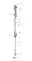
- FIG. 1is a reference picture of the assembled bicycle seat post in accordance with a first embodiment of the present invention.
- FIG. 2is a stereogram of the hydraulic actuator in accordance with a first embodiment of the present invention.
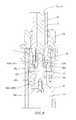
- FIG. 3is a sectional plan view of the hydraulic actuator in accordance with a first embodiment of the present invention.
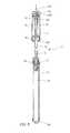
- FIG. 4is a cutaway view of the hydraulic actuator in accordance with a first embodiment of the present invention.
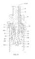
- FIG. 5is a cutaway view of the upper half of the hydraulic actuator in accordance with a first embodiment of the present invention.
- FIG. 6is a sectional plan view of the upper half of the hydraulic actuator in accordance with a first embodiment of the present invention.
- FIG. 7is a cutaway view of the lower half of the hydraulic actuator in accordance with a first embodiment of the present invention.
- FIG. 8is a sectional plan view of the lower half of the hydraulic actuator in accordance with a first embodiment of the present invention.
- FIG. 9is a sectional view of the hydraulic actuator in a state that the oil passages communicate with one another in accordance with a first embodiment of the present invention.
- FIG. 10is a sectional view of the upper half of the hydraulic actuator in a state that the oil passages communicate with one another in accordance with a first embodiment of the present invention.
- FIG. 11is a sectional view of the lower half of the hydraulic actuator in a state that the oil passages communicate with one another in accordance with a first embodiment of the present invention.
- FIG. 12is a sectional view that the hydraulic actuator performs the seat height adjustments in accordance with a first embodiment of the present invention.
- FIG. 13is a sectional view of the lower half of the hydraulic actuator in the state of performing the seat height adjustments in accordance with a first embodiment of the present invention.
- FIG. 14is a sectional view of the lower half of the hydraulic actuator in a state that the oil passages are closed in accordance with a second embodiment of the present invention.
- FIG. 15is a sectional view of the lower half of the hydraulic actuator in a state that the oil passages communicate with one another in accordance with a second embodiment of the present invention.
- FIG. 16is a sectional view of the lower half of the hydraulic actuator in a state that the oil passages are closed in accordance with a third embodiment of the present invention.
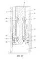
- FIG. 17is a sectional view of the lower half of the hydraulic actuator in a state that the oil passages communicate with one another in accordance with a third embodiment of the present invention.
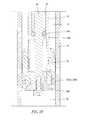
- FIG. 18is a sectional view of the lower half of the hydraulic actuator in a state that the oil passages are closed in accordance with a fourth embodiment of the present invention.
- FIG. 19is a sectional view of the lower half of the hydraulic actuator in a state that the oil passages communicate with one another in accordance with a fourth embodiment of the present invention.
- FIG. 20is a sectional view of the lower half of the hydraulic actuator in a state that the oil passages are closed in accordance with a fifth embodiment of the present invention.
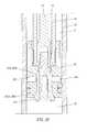
- FIG. 21is a sectional view of the lower half of the hydraulic actuator in a state that the oil passages communicate with one another in accordance with a fifth embodiment of the present invention.
- the bicycle seat post disclosed in the present inventionis provided with an outer tube 1 which has a bottom end inserted into an inner tube ⁇ arranged within the outer tube 1 , and a hydraulic actuator 3 which is configured in the outer tube 1 as well as the inner tube ⁇ ; wherein, the outer tube 1 has a bottom end received and secured in the seat tube 4 of the bicycle frame; and wherein the inner tube 2 has a top end configured with a clamp 20 for fastening the fixing rod disposed on the bottom end of the seat so as to tighten firmly.
- the hydraulic actuator 3includes an upper cylinder barrel 30 , an intermediate cylinder barrel 31 , a lower cylinder barrel 32 , and a pin 33 arranged in the intermediate cylinder barrel 31 .
- the intermediate cylinder barrel 31is arranged between the upper cylinder barrel 30 and the lower cylinder barrel 32 , and has two ends respectively inserted into the upper cylinder barrel 30 and the lower cylinder barrel 32 .
- the upper cylinder barrel 30has an upper opening and a lower opening respectively screwed with a first upper sealing plug 301 and a first lower sealing plug 302 which are metallic and hollow (as shown in FIG. 3 to FIG. 6 ).
- the top end of the first upper sealing plug 301has an outer wall 3010 configured to the external side of the opening of the upper cylinder barrel 30 , and said outer wall 3010 is provided with threads allowed to mate with the internal threads of the aforesaid inner tube 2 (as shown in FIG. 1 ) so as to fasten the top end of the upper cylinder barrel 30 .
- the interior of the top end of the upper cylinder barrel 30is arranged with a bearer 303 (as shown in FIG. 3 and FIG. 6 ) whose top surface has a concave receiving space 3030 disposed with a perforation 3031 at the middle thereof.
- the outer wall of the top end of the bearer 303is engaged with the inner wall of the first upper sealing plug 301 by a threaded portion 3032 , and further the inner wall of the perforation 3031 at the bottom surface of the bearer 303 is engaged with the outer wall of the top end of the intermediate cylinder barrel 31 by a threaded portion 3033 , so as to allow the upper cylinder barrel 30 , the first upper sealing plug 301 , the bearer 303 as well as the intermediate cylinder barrel 31 to be combined into an integral whole (as shown in FIG. 5 and FIG. 6 ).
- the top end of the pin 33is inserted into the receiving space 3030 of the bearer 303 and further secured to an upper pin 330 whose top end extends through the first sealing plug 301 .
- the receiving space 3030 of the bearer 303is disposed with an upper spring 34 mounted between the outer wall of the top end of the pin 33 and the inner wall of the receiving space 3030 ; the upper spring 34 has a top end fastened to the shoulder 331 of the top end of the pin 33 and a bottom end touching the bottom surface of the receiving space 3030 of the bearer 303 , and therefore, the upper spring 34 may exert a force on the pin 33 and the upper pin 330 so as to push them to move upward.
- the outer side of the intermediate cylinder barrel 31 inside the upper cylinder barrel 30is configured with a floating piston 35 , as shown in FIG.
- an upper oil compartment 36is arranged inside the upper cylinder barrel 30 between the floating piston 35 and the first lower sealing plug 302 ; an air compartment 37 is arranged inside the upper cylinder barrel 30 between the top of the floating piston 35 and the first upper sealing plug 301 .
- the wall of the intermediate cylinder barrel 31 relative to the portion beneath the floating piston 35is provided with an oil hole 310 ; the outer wall of the pin 33 relative to the portion above the oil hole 310 touches the wall of the intermediate cylinder barrel 31 by first oil rings 311 so as to form an oil passage 312 between the outer wall of the pin 33 relative to the portion beneath the first oil rings 311 and the inner wall of the intermediate cylinder barrel 31 ; the oil passage 312 may communicate with the upper oil compartment 36 via the oil hole 310 , so that the oil passage 312 is allowed to be a part of the upper oil compartment 36 .
- the lower cylinder barrel 32has an upper opening and a lower opening respectively screwed with a second upper sealing plug 320 and a second lower sealing plug 321 so as to seal the upper and the lower openings of the lower cylinder barrel 32 ; wherein the second upper sealing plug 320 is disposed with a perforation at the middle thereof so as to allow the bottom end of the intermediate cylinder barrel 31 to insert through and into the lower cylinder barrel 32 .
- the bottom end of the intermediate cylinder barrel 31 inside the lower cylinder barrel 31is screwed with a hollow valve 38 of which the outer wall touches the inner wall of the lower cylinder barrel 32 via second oil rings 380 .
- the interior of the hollow valve 38is arranged with a lower pin 332 attached to the pin 33 ; the exterior of the lower end of the lower pin 332 is secured with a lower valve 381 of which the outer side is the outer incline 3810 ; the bottom of the valve 38 is provided with a hollow opening of which the inner wall relative to the outer incline 3810 provides an inner incline 3800 ; the space positioned inside the lower cylinder barrel 32 and also under the lower valve 381 forms a lower oil compartment 39 when the inner incline 3800 and the outer incline 3810 firmly engage each other.
- the bottom end of the pin 33is provided with a diameter-narrowed section 333 having a narrower outer diameter than the pin body; the outer side of the diameter-narrowed section 333 is configured with an upper valve 382 of which the outer side is arranged with an outer incline 3820 ; the inner side of the bottom end of the intermediate cylinder barrel 31 relative to the outer incline 3820 provides an inner incline 313 .
- the exterior of the lower pin 332is arranged with a lower spring 40 ; the lower spring 40 has a top end touching the bottom end of the upper valve 382 , and a bottom end against a plane surface of the lower pin 332 , and therefore, the lower spring 40 may exert a force on the upper valve 382 to push it to move upward so as to allow the outer incline 3820 of the upper valve 382 to kiss the inner incline 313 of the bottom end of the intermediate cylinder barrel 31 .
- the outer wall of the valve 38 under the upper valve 382is provided with a valve aperture 384 which enables the inner and outer sides of the valve 38 to intercommunicate; an intermediate oil compartment 41 , which communicates with the interior of the valve 38 by the valve aperture 384 , is configured between the inner wall of the lower cylinder barrel 32 and the outer wall of the valve 38 above the valve aperture 384 .
- the seat height adjustmentsmay proceed as the following.
- the upper valve 382 and the lower valve 381 disclosed in the present inventionmay close the oil compartments 36 , 41 and 39 to disconnect the oil passages so as to lock the seat, and thus, the seat cannot be pushed down or pulled up so as to be firmly combined with the bicycle frame as a whole.
- FIG. 14 and FIG. 15the sectional view of the lower half of the hydraulic actuator in a state that the oil passages are closed and the sectional view of the lower half of the hydraulic actuator in a state that the oil passages communicate with one another are illustrated in accordance with a second embodiment of the present invention.
- the upper valve 382 shown in said second embodimentis secured to the bottom end of the pin 33 so that the axial displacements cannot be carried out along the pin 33 ;
- the lower valve 381is configured to the outer side of the diameter-narrowed section 333 of the lower pin 332 ;
- the lower spring 40 arranged under the lower valve 381is disposed to the outer side of a spring sleeve 42 ;
- a bolt 43 of which the top end is screwed with the bottom end of the lower pin 332passes through the middle of the spring sleeve 42 so as to enable the spring sleeve 42 , the pin 33 and the lower pin 332 to be combined together and to operate simultaneously as a whole.
- the outer side of the bottom end of the spring sleeve 42is provided with a protrudent ring 420 protruding outward for holding the bottom end of the lower spring 40 so as to allow the top end of the lower spring 40 to push the lower valve 381 up.
- the upper valve 382 and the lower valve 381close the oil compartments 36 , 41 and 39 so as to stop the oil in each compartment flowing into one another.
- the bicycle seat heightis allowed to be adjusted; when the pin 33 is pushed down, the upper spring 34 is compressed, and the pin 33 moves down, so as to drive the lower pin 332 combined with the pin 33 , the upper valve 382 and the lower valve 381 simultaneously to move down together; the upper valve 382 and the lower valve 381 respectively disconnect from the inner incline 313 of the intermediate cylinder barrel 31 and the inner incline 3800 of the valve 38 , as shown in FIG. 15 , so that the upper oil compartment 36 , the intermediate oil compartment 41 and the lower oil compartment 39 are allowed to communicate with one another for seat height adjustments.
- FIG. 16 and FIG. 17the sectional view of the lower half of the hydraulic actuator in a state that the oil passages are closed and the sectional view of the lower half of the hydraulic actuator in a state that the oil passages communicate with one another are illustrated in accordance with a third embodiment of the present invention; referring to FIG. 18 and FIG. 19 , the sectional view of the lower half of the hydraulic actuator in a state that the oil passages are closed and the sectional view of the lower half of the hydraulic actuator in a state that the oil passages communicate with one another are illustrated in accordance with a fourth embodiment of the present invention; referring to FIG. 20 and FIG.
- FIG. 21the sectional view of the lower half of the hydraulic actuator in a state that the oil passages are closed and the sectional view of the lower half of the hydraulic actuator in a state that the oil passages communicate with one another are illustrated in accordance with a fifth embodiment of the present invention.
- Said third, fourth and fifth embodiments of the present inventionare NOT configured with a lower spring 40 , wherein the upper valve 382 disclosed in said third embodiment is an 0 -ring, and the outer surface of the pin 33 relative to the portion arranged with the upper valve 382 is provided with an upper ringed-recess 334 for receiving and fastening the upper valve 382 of which the outer surface projects from the outer surface of the pin 33 .
- the outer wall of the upper valve 382touches and kisses the inner wall of the intermediate cylinder barrel 31 above the valve aperture 384 ; the inner wall of the hollow valve 38 relative to the portion arranged with the lower valve 381 is provided with a lower ringed-recess 385 for receiving and engaging the outer surface of the lower valve 381 which is also an O-ring and of which the inner surface projects from the lower ringed-recess 385 .
- the outer wall of the bottom of the pin 33provides a vertical face 335 having a wider outer diameter than the pin body; the outer surface of the pin 33 above the vertical face 335 is provided with an arc concave surface 336 with a narrower outer diameter.
- the structureis illustrated in accordance with a fourth embodiment of the present invention.
- the difference between said fourth and said third embodimentsis described as the following; the structure of the lower valve 381 disclosed in said fourth embodiment is identical to that disclosed in said first embodiment of the present invention, except that the lower valve 381 , of which the outer surface is the outer incline 3810 , is secured to the outer side of the bottom end of the pin 33 and that the hollow opening of the bottom end of the valve 38 relative to the inner wall of the outer incline 3810 is provided with an inner incline 3800 , so that the intermediate oil compartment 41 and the lower oil compartment 39 will be closed when the inner incline 3800 kisses the outer incline 3810 .
- the structure of a fifth embodiment of the present inventionis disclosed.
- the upper valve 382 and the lower valve 381are one-piece formed, provided with a hollow tubular structure, and secured to the outer side of the bottom end of the pin 33 ; the outer side of the upper valve 382 and the external side of the lower valve 381 respectively provide the outer inclines 3820 and 3810 which may firmly engage with the inner inclines 313 and 3800 disposed to the valve 38 , so as to disconnect the upper oil compartment 36 , the intermediate oil compartment 41 and the lower oil compartment 39 when the pin 33 is in a state of locking.
Landscapes
- Engineering & Computer Science (AREA)
- General Engineering & Computer Science (AREA)
- Mechanical Engineering (AREA)
- Fluid-Damping Devices (AREA)
Abstract
Description
- I. As shown in
FIG. 9 andFIG. 10 , the bicycle seat height may be adjusted when the regulating knob is set to press down theupper pin 330, thepin 33 and thelower pin 332 which are arranged in thehydraulic actuator 3; when thepin 33 is pressed down, theupper spring 34 is compressed, and thepin 33 moves down so as to drive thelower pin 332 combined with thepin 33, theupper valve 382 and thelower valve 381 simultaneously to move down together; theupper valve 382 and thelower valve 381 respectively disconnect from theinner incline 313 of theintermediate cylinder barrel 31 and theinner incline 3800 of thevalve 38, as shown inFIG. 11 , so as to allow theupper oil compartment 36, theintermediate oil compartment 41 and thelower oil compartment 39 to communicate with one another, and thus theupper cylinder barrel 30, theintermediate cylinder barrel 31, thepin 33, thevalve 38 and the seat are allowed to be simultaneously driven as a whole for height adjustments; in addition, the oil distribution in each oil compartment will vary according to the varied heights of the seat, as shown inFIG. 12 . - II. As shown in
FIG. 13 , the regulating knob may be set to stay in the state of locking after the seat height is set. Theupper spring 34 pushes thepin 33 up back to its normal position so as to allow thelower valve 381 to kiss theinner incline 3800 of thevalve 38 and allow theupper valve 382 to kiss theinner incline 313 of theintermediate cylinder barrel 31; in addition, theupper valve 382 is also pushed up by thelower spring 40 to firmly touch and kiss theinner incline 313 of theintermediate cylinder barrel 31; thus, theupper valve 382 and thelower valve 381 close theupper oil compartment 36, theintermediate oil compartment 41 and thelower oil compartment 39 so as to stop the oil in each compartment flowing into one another; it is because that the oil within theintermediate oil compartment 41 may prevent thevalve 38, theupper valve 382 and thelower valve 381 from moving up with thepin 33, so as to cause the height of the seat to be set to stop the seat moving up and enable the seat to be firmly combined with the bicycle frame as a whole without any disconnection, when the regulating knob is set to stay in the state of locking.
- I. As shown in
Claims (8)
Priority Applications (1)
| Application Number | Priority Date | Filing Date | Title |
|---|---|---|---|
| US13/753,594US9126647B2 (en) | 2013-01-30 | 2013-01-30 | Bicycle seat post structure |
Applications Claiming Priority (1)
| Application Number | Priority Date | Filing Date | Title |
|---|---|---|---|
| US13/753,594US9126647B2 (en) | 2013-01-30 | 2013-01-30 | Bicycle seat post structure |
Publications (2)
| Publication Number | Publication Date |
|---|---|
| US20140208933A1 US20140208933A1 (en) | 2014-07-31 |
| US9126647B2true US9126647B2 (en) | 2015-09-08 |
Family
ID=51221513
Family Applications (1)
| Application Number | Title | Priority Date | Filing Date |
|---|---|---|---|
| US13/753,594Expired - Fee RelatedUS9126647B2 (en) | 2013-01-30 | 2013-01-30 | Bicycle seat post structure |
Country Status (1)
| Country | Link |
|---|---|
| US (1) | US9126647B2 (en) |
Cited By (38)
| Publication number | Priority date | Publication date | Assignee | Title |
|---|---|---|---|---|
| US20130221713A1 (en)* | 2008-11-25 | 2013-08-29 | Fox Factory, Inc. | Seat post |
| US20160214447A1 (en)* | 2013-09-02 | 2016-07-28 | Re.Mo.Bic. Gmbh | Device for detachably fixing two parts of a bicycle pump to each other, which parts can be moved in relation to each other |
| US9650094B2 (en) | 2010-07-02 | 2017-05-16 | Fox Factory, Inc. | Lever assembly for positive lock adjustable seatpost |
| US9682604B2 (en) | 2009-03-19 | 2017-06-20 | Fox Factory, Inc. | Methods and apparatus for selective spring pre-load adjustment |
| US20170197680A1 (en)* | 2016-01-13 | 2017-07-13 | J. D Components Co., Ltd. | Pneumatic and hydraulic elevating seat tube assembly of bicycle |
| US9903528B1 (en)* | 2014-09-22 | 2018-02-27 | Joshua Terry Hatch | Telescoping lock mechanism |
| US9957008B1 (en)* | 2017-03-06 | 2018-05-01 | Taiwan Hodaka Industrial Co., Ltd. | Bicycle seatpost structure |
| US10029172B2 (en) | 2008-11-25 | 2018-07-24 | Fox Factory, Inc. | Methods and apparatus for virtual competition |
| US10036443B2 (en) | 2009-03-19 | 2018-07-31 | Fox Factory, Inc. | Methods and apparatus for suspension adjustment |
| US10040329B2 (en) | 2009-01-07 | 2018-08-07 | Fox Factory, Inc. | Method and apparatus for an adjustable damper |
| US10047817B2 (en) | 2009-01-07 | 2018-08-14 | Fox Factory, Inc. | Method and apparatus for an adjustable damper |
| US10060499B2 (en) | 2009-01-07 | 2018-08-28 | Fox Factory, Inc. | Method and apparatus for an adjustable damper |
| US20180244330A1 (en)* | 2017-02-24 | 2018-08-30 | Shimano Inc. | Bicycle telescopic apparatus |
| US10072724B2 (en) | 2008-08-25 | 2018-09-11 | Fox Factory, Inc. | Methods and apparatus for suspension lock out and signal generation |
| US10086670B2 (en) | 2009-03-19 | 2018-10-02 | Fox Factory, Inc. | Methods and apparatus for suspension set up |
| US10094443B2 (en) | 2009-01-07 | 2018-10-09 | Fox Factory, Inc. | Bypass for a suspension damper |
| CN108668621A (en)* | 2018-03-18 | 2018-10-19 | 魏磊 | A kind of industry of planting forest or fruit tress special electric tricycle |
| US10145435B2 (en) | 2009-03-19 | 2018-12-04 | Fox Factory, Inc. | Methods and apparatus for suspension adjustment |
| US10160511B2 (en) | 2009-01-07 | 2018-12-25 | Fox Factory, Inc. | Method and apparatus for an adjustable damper |
| US10330171B2 (en) | 2012-05-10 | 2019-06-25 | Fox Factory, Inc. | Method and apparatus for an adjustable damper |
| US10358180B2 (en) | 2017-01-05 | 2019-07-23 | Sram, Llc | Adjustable seatpost |
| US10400847B2 (en) | 2009-01-07 | 2019-09-03 | Fox Factory, Inc. | Compression isolator for a suspension damper |
| US10406883B2 (en) | 2009-10-13 | 2019-09-10 | Fox Factory, Inc. | Methods and apparatus for controlling a fluid damper |
| US10415662B2 (en) | 2009-01-07 | 2019-09-17 | Fox Factory, Inc. | Remotely operated bypass for a suspension damper |
| US20190300085A1 (en)* | 2018-03-29 | 2019-10-03 | Shimano Inc. | Telescopic apparatus |
| US10443671B2 (en) | 2009-01-07 | 2019-10-15 | Fox Factory, Inc. | Remotely operated bypass for a suspension damper |
| US10677309B2 (en) | 2011-05-31 | 2020-06-09 | Fox Factory, Inc. | Methods and apparatus for position sensitive suspension damping |
| US10697514B2 (en) | 2010-01-20 | 2020-06-30 | Fox Factory, Inc. | Remotely operated bypass for a suspension damper |
| US10731724B2 (en) | 2009-10-13 | 2020-08-04 | Fox Factory, Inc. | Suspension system |
| US10737546B2 (en) | 2016-04-08 | 2020-08-11 | Fox Factory, Inc. | Electronic compression and rebound control |
| US10821795B2 (en) | 2009-01-07 | 2020-11-03 | Fox Factory, Inc. | Method and apparatus for an adjustable damper |
| US10933935B2 (en) | 2018-04-02 | 2021-03-02 | Wolf Tooth Components, LLC | Linear actuator system |
| US20210206443A1 (en)* | 2020-01-08 | 2021-07-08 | Shimano Inc. | Telescopic apparatus for human-powered vehicle |
| US11279199B2 (en) | 2012-01-25 | 2022-03-22 | Fox Factory, Inc. | Suspension damper with by-pass valves |
| US11299233B2 (en) | 2009-01-07 | 2022-04-12 | Fox Factory, Inc. | Method and apparatus for an adjustable damper |
| US11306798B2 (en) | 2008-05-09 | 2022-04-19 | Fox Factory, Inc. | Position sensitive suspension damping with an active valve |
| US12122205B2 (en) | 2009-01-07 | 2024-10-22 | Fox Factory, Inc. | Active valve for an internal bypass |
| US12151758B2 (en) | 2022-09-25 | 2024-11-26 | Shimano Inc. | Actuator device and rider-posture changing apparatus for human-powered vehicle |
Families Citing this family (8)
| Publication number | Priority date | Publication date | Assignee | Title |
|---|---|---|---|---|
| CA2959649C (en) | 2014-08-26 | 2023-09-26 | Nine Point Eight Inc. | Systems and methods for supporting telescoping elements |
| EP3245121B1 (en)* | 2015-01-13 | 2020-04-15 | Crank Brothers, Inc. | Adjustable height seat post |
| US10759483B2 (en) | 2015-10-01 | 2020-09-01 | Shimano Inc. | Bicycle and electrical seatpost assembly |
| AT518752A1 (en)* | 2016-06-06 | 2017-12-15 | Lupaan Gmbh | Telescopic seat post |
| TWI589475B (en)* | 2016-08-31 | 2017-07-01 | 巨大機械工業股份有限公司 | Adjustable seat tube structure and bicycle thereof |
| US11180212B2 (en)* | 2018-07-17 | 2021-11-23 | Shimano Inc. | Fluid flow control structure for a telescopic apparatus of a human powered vehicle |
| TWM616687U (en)* | 2021-01-25 | 2021-09-11 | 久鼎金屬實業股份有限公司 | Gas hydraulic control valve |
| US12179870B2 (en)* | 2022-02-18 | 2024-12-31 | Sram, Llc | Seat post assembly with an adjustable stroke |
Citations (8)
| Publication number | Priority date | Publication date | Assignee | Title |
|---|---|---|---|---|
| TW478461U (en) | 2000-12-08 | 2002-03-01 | Kalloy Ind Co Ltd | Structure for shock-absorbing tube capable of ascending and descending |
| TWM342324U (en) | 2008-04-21 | 2008-10-11 | Kind Shock Hi Tech Co Ltd | Adjustable type bicycle seat post structure |
| US7845602B1 (en)* | 2006-02-09 | 2010-12-07 | Primos, Inc. | Telescoping support stand apparatus |
| TW201217208A (en) | 2010-10-29 | 2012-05-01 | Kind Shock Hi Tech Co Ltd | reducing air cavity and the sluggish height adjustment, and lowering the collision and wear damage on the interior parts |
| US8328454B2 (en)* | 2008-06-30 | 2012-12-11 | Specialized Bicycle Components, Inc. | Vertically adjustable bicycle assembly |
| US8398104B2 (en)* | 2010-10-28 | 2013-03-19 | Jung Yu Hsu | Bicycle seat adjustable device |
| US8511655B2 (en)* | 2010-10-21 | 2013-08-20 | Durashox Technology Co., Ltd. | Bicycle seat post |
| US8814109B2 (en)* | 2010-07-02 | 2014-08-26 | Fox Factory, Inc. | Positive lock adjustable seat post |
- 2013
- 2013-01-30USUS13/753,594patent/US9126647B2/ennot_activeExpired - Fee Related
Patent Citations (8)
| Publication number | Priority date | Publication date | Assignee | Title |
|---|---|---|---|---|
| TW478461U (en) | 2000-12-08 | 2002-03-01 | Kalloy Ind Co Ltd | Structure for shock-absorbing tube capable of ascending and descending |
| US7845602B1 (en)* | 2006-02-09 | 2010-12-07 | Primos, Inc. | Telescoping support stand apparatus |
| TWM342324U (en) | 2008-04-21 | 2008-10-11 | Kind Shock Hi Tech Co Ltd | Adjustable type bicycle seat post structure |
| US8328454B2 (en)* | 2008-06-30 | 2012-12-11 | Specialized Bicycle Components, Inc. | Vertically adjustable bicycle assembly |
| US8814109B2 (en)* | 2010-07-02 | 2014-08-26 | Fox Factory, Inc. | Positive lock adjustable seat post |
| US8511655B2 (en)* | 2010-10-21 | 2013-08-20 | Durashox Technology Co., Ltd. | Bicycle seat post |
| US8398104B2 (en)* | 2010-10-28 | 2013-03-19 | Jung Yu Hsu | Bicycle seat adjustable device |
| TW201217208A (en) | 2010-10-29 | 2012-05-01 | Kind Shock Hi Tech Co Ltd | reducing air cavity and the sluggish height adjustment, and lowering the collision and wear damage on the interior parts |
Cited By (117)
| Publication number | Priority date | Publication date | Assignee | Title |
|---|---|---|---|---|
| US11306798B2 (en) | 2008-05-09 | 2022-04-19 | Fox Factory, Inc. | Position sensitive suspension damping with an active valve |
| US10072724B2 (en) | 2008-08-25 | 2018-09-11 | Fox Factory, Inc. | Methods and apparatus for suspension lock out and signal generation |
| US10550909B2 (en) | 2008-08-25 | 2020-02-04 | Fox Factory, Inc. | Methods and apparatus for suspension lock out and signal generation |
| US11162555B2 (en) | 2008-08-25 | 2021-11-02 | Fox Factory, Inc. | Methods and apparatus for suspension lock out and signal generation |
| US12170137B2 (en) | 2008-11-25 | 2024-12-17 | Fox Factory, Inc. | Methods and apparatus for virtual competition |
| US10537790B2 (en) | 2008-11-25 | 2020-01-21 | Fox Factory, Inc. | Methods and apparatus for virtual competition |
| US11257582B2 (en) | 2008-11-25 | 2022-02-22 | Fox Factory, Inc. | Methods and apparatus for virtual competition |
| US20210339816A1 (en)* | 2008-11-25 | 2021-11-04 | Fox Factory, Inc. | Seat post |
| US10029172B2 (en) | 2008-11-25 | 2018-07-24 | Fox Factory, Inc. | Methods and apparatus for virtual competition |
| US20200070914A1 (en)* | 2008-11-25 | 2020-03-05 | Fox Factory, Inc. | Seat post |
| US9422018B2 (en)* | 2008-11-25 | 2016-08-23 | Fox Factory, Inc. | Seat post |
| US11875887B2 (en) | 2008-11-25 | 2024-01-16 | Fox Factory, Inc. | Methods and apparatus for virtual competition |
| US10472013B2 (en)* | 2008-11-25 | 2019-11-12 | Fox Factory, Inc. | Seat post |
| US20130221713A1 (en)* | 2008-11-25 | 2013-08-29 | Fox Factory, Inc. | Seat post |
| US11043294B2 (en) | 2008-11-25 | 2021-06-22 | Fox Factoory, Inc. | Methods and apparatus for virtual competition |
| US12033739B2 (en) | 2008-11-25 | 2024-07-09 | Fox Factory, Inc. | Methods and apparatus for virtual competition |
| US11021204B2 (en)* | 2008-11-25 | 2021-06-01 | Fox Factory, Inc. | Seat post |
| US11869651B2 (en) | 2008-11-25 | 2024-01-09 | Fox Factory, Inc. | Methods and apparatus for virtual competition |
| US11961602B2 (en) | 2008-11-25 | 2024-04-16 | Fox Factory, Inc. | Methods and apparatus for virtual competition |
| US11897571B2 (en)* | 2008-11-25 | 2024-02-13 | Fox Factory, Inc. | Seat post |
| US11794543B2 (en) | 2009-01-07 | 2023-10-24 | Fox Factory, Inc. | Method and apparatus for an adjustable damper |
| US12091122B2 (en) | 2009-01-07 | 2024-09-17 | Fox Factory, Inc. | Method and apparatus for an adjustable damper |
| US10160511B2 (en) | 2009-01-07 | 2018-12-25 | Fox Factory, Inc. | Method and apparatus for an adjustable damper |
| US10336148B2 (en) | 2009-01-07 | 2019-07-02 | Fox Factory, Inc. | Method and apparatus for an adjustable damper |
| US10336149B2 (en) | 2009-01-07 | 2019-07-02 | Fox Factory, Inc. | Method and apparatus for an adjustable damper |
| US10094443B2 (en) | 2009-01-07 | 2018-10-09 | Fox Factory, Inc. | Bypass for a suspension damper |
| US11866120B2 (en) | 2009-01-07 | 2024-01-09 | Fox Factory, Inc. | Method and apparatus for an adjustable damper |
| US10400847B2 (en) | 2009-01-07 | 2019-09-03 | Fox Factory, Inc. | Compression isolator for a suspension damper |
| US11976706B2 (en) | 2009-01-07 | 2024-05-07 | Fox Factory, Inc. | Remotely operated bypass for a suspension damper |
| US10415662B2 (en) | 2009-01-07 | 2019-09-17 | Fox Factory, Inc. | Remotely operated bypass for a suspension damper |
| US12044286B2 (en) | 2009-01-07 | 2024-07-23 | Fox Factory, Inc. | Compression isolator for a suspension damper |
| US11660924B2 (en) | 2009-01-07 | 2023-05-30 | Fox Factory, Inc. | Method and apparatus for an adjustable damper |
| US11549565B2 (en) | 2009-01-07 | 2023-01-10 | Fox Factory, Inc. | Method and apparatus for an adjustable damper |
| US10443671B2 (en) | 2009-01-07 | 2019-10-15 | Fox Factory, Inc. | Remotely operated bypass for a suspension damper |
| US10060499B2 (en) | 2009-01-07 | 2018-08-28 | Fox Factory, Inc. | Method and apparatus for an adjustable damper |
| US10047817B2 (en) | 2009-01-07 | 2018-08-14 | Fox Factory, Inc. | Method and apparatus for an adjustable damper |
| US10040329B2 (en) | 2009-01-07 | 2018-08-07 | Fox Factory, Inc. | Method and apparatus for an adjustable damper |
| US11890908B2 (en) | 2009-01-07 | 2024-02-06 | Fox Factory, Inc. | Method and apparatus for an adjustable damper |
| US11519477B2 (en) | 2009-01-07 | 2022-12-06 | Fox Factory, Inc. | Compression isolator for a suspension damper |
| US11499601B2 (en) | 2009-01-07 | 2022-11-15 | Fox Factory, Inc. | Remotely operated bypass for a suspension damper |
| US10670106B2 (en) | 2009-01-07 | 2020-06-02 | Fox Factory, Inc. | Method and apparatus for an adjustable damper |
| US11408482B2 (en) | 2009-01-07 | 2022-08-09 | Fox Factory, Inc. | Bypass for a suspension damper |
| US12122205B2 (en) | 2009-01-07 | 2024-10-22 | Fox Factory, Inc. | Active valve for an internal bypass |
| US10723409B2 (en) | 2009-01-07 | 2020-07-28 | Fox Factory, Inc. | Method and apparatus for an adjustable damper |
| US11299233B2 (en) | 2009-01-07 | 2022-04-12 | Fox Factory, Inc. | Method and apparatus for an adjustable damper |
| US12134293B2 (en) | 2009-01-07 | 2024-11-05 | Fox Factory, Inc. | Method and apparatus for an adjustable damper |
| US11173765B2 (en) | 2009-01-07 | 2021-11-16 | Fox Factory, Inc. | Method and apparatus for an adjustable damper |
| US10781879B2 (en) | 2009-01-07 | 2020-09-22 | Fox Factory, Inc. | Bypass for a suspension damper |
| US11168758B2 (en) | 2009-01-07 | 2021-11-09 | Fox Factory, Inc. | Method and apparatus for an adjustable damper |
| US10800220B2 (en) | 2009-01-07 | 2020-10-13 | Fox Factory, Inc. | Method and apparatus for an adjustable damper |
| US12257871B2 (en) | 2009-01-07 | 2025-03-25 | Fox Factory, Inc. | Method and apparatus for an adjustable damper |
| US10807433B2 (en) | 2009-01-07 | 2020-10-20 | Fox Factory, Inc. | Method and apparatus for an adjustable damper |
| US10814689B2 (en) | 2009-01-07 | 2020-10-27 | Fox Factory, Inc. | Method and apparatus for an adjustable damper |
| US10821795B2 (en) | 2009-01-07 | 2020-11-03 | Fox Factory, Inc. | Method and apparatus for an adjustable damper |
| US12371122B2 (en) | 2009-01-07 | 2025-07-29 | Fox Factory, Inc. | Method and apparatus for an adjustable damper |
| US12377699B2 (en) | 2009-01-07 | 2025-08-05 | Fox Factory, Inc. | Method and apparatus for an adjustable damper |
| US10414236B2 (en) | 2009-03-19 | 2019-09-17 | Fox Factory, Inc. | Methods and apparatus for selective spring pre-load adjustment |
| US10145435B2 (en) | 2009-03-19 | 2018-12-04 | Fox Factory, Inc. | Methods and apparatus for suspension adjustment |
| US11655873B2 (en) | 2009-03-19 | 2023-05-23 | Fox Factory, Inc. | Methods and apparatus for suspension adjustment |
| US9682604B2 (en) | 2009-03-19 | 2017-06-20 | Fox Factory, Inc. | Methods and apparatus for selective spring pre-load adjustment |
| US12163569B2 (en) | 2009-03-19 | 2024-12-10 | Fox Factory, Inc. | Methods and apparatus for suspension adjustment |
| US11619278B2 (en) | 2009-03-19 | 2023-04-04 | Fox Factory, Inc. | Methods and apparatus for suspension adjustment |
| US12103349B2 (en) | 2009-03-19 | 2024-10-01 | Fox Factory, Inc. | Methods and apparatus for selective spring pre-load adjustment |
| US10036443B2 (en) | 2009-03-19 | 2018-07-31 | Fox Factory, Inc. | Methods and apparatus for suspension adjustment |
| US10591015B2 (en) | 2009-03-19 | 2020-03-17 | Fox Factory, Inc. | Methods and apparatus for suspension adjustment |
| US11413924B2 (en) | 2009-03-19 | 2022-08-16 | Fox Factory, Inc. | Methods and apparatus for selective spring pre-load adjustment |
| US11920655B2 (en) | 2009-03-19 | 2024-03-05 | Fox Factory, Inc. | Methods and apparatus for suspension adjustment |
| US10086670B2 (en) | 2009-03-19 | 2018-10-02 | Fox Factory, Inc. | Methods and apparatus for suspension set up |
| US10731724B2 (en) | 2009-10-13 | 2020-08-04 | Fox Factory, Inc. | Suspension system |
| US11279198B2 (en) | 2009-10-13 | 2022-03-22 | Fox Factory, Inc. | Methods and apparatus for controlling a fluid damper |
| US12005755B2 (en) | 2009-10-13 | 2024-06-11 | Fox Factory, Inc. | Methods and apparatus for controlling a fluid damper |
| US11859690B2 (en) | 2009-10-13 | 2024-01-02 | Fox Factory, Inc. | Suspension system |
| US10406883B2 (en) | 2009-10-13 | 2019-09-10 | Fox Factory, Inc. | Methods and apparatus for controlling a fluid damper |
| US11708878B2 (en) | 2010-01-20 | 2023-07-25 | Fox Factory, Inc. | Remotely operated bypass for a suspension damper |
| US10697514B2 (en) | 2010-01-20 | 2020-06-30 | Fox Factory, Inc. | Remotely operated bypass for a suspension damper |
| US10086892B2 (en) | 2010-07-02 | 2018-10-02 | Fox Factory, Inc. | Lever assembly for positive lock adjustable seat post |
| US11866110B2 (en) | 2010-07-02 | 2024-01-09 | Fox Factory, Inc. | Lever assembly for positive lock adjustable seat post |
| US9650094B2 (en) | 2010-07-02 | 2017-05-16 | Fox Factory, Inc. | Lever assembly for positive lock adjustable seatpost |
| US10843753B2 (en) | 2010-07-02 | 2020-11-24 | Fox Factory, Inc. | Lever assembly for positive lock adjustable seat post |
| US10677309B2 (en) | 2011-05-31 | 2020-06-09 | Fox Factory, Inc. | Methods and apparatus for position sensitive suspension damping |
| US11796028B2 (en) | 2011-05-31 | 2023-10-24 | Fox Factory, Inc. | Methods and apparatus for position sensitive suspension damping |
| US11958328B2 (en) | 2011-09-12 | 2024-04-16 | Fox Factory, Inc. | Methods and apparatus for suspension set up |
| US10759247B2 (en) | 2011-09-12 | 2020-09-01 | Fox Factory, Inc. | Methods and apparatus for suspension set up |
| US11760150B2 (en) | 2012-01-25 | 2023-09-19 | Fox Factory, Inc. | Suspension damper with by-pass valves |
| US11279199B2 (en) | 2012-01-25 | 2022-03-22 | Fox Factory, Inc. | Suspension damper with by-pass valves |
| US10330171B2 (en) | 2012-05-10 | 2019-06-25 | Fox Factory, Inc. | Method and apparatus for an adjustable damper |
| US10859133B2 (en) | 2012-05-10 | 2020-12-08 | Fox Factory, Inc. | Method and apparatus for an adjustable damper |
| US12038062B2 (en) | 2012-05-10 | 2024-07-16 | Fox Factory, Inc. | Method and apparatus for an adjustable damper |
| US11629774B2 (en) | 2012-05-10 | 2023-04-18 | Fox Factory, Inc. | Method and apparatus for an adjustable damper |
| US20160214447A1 (en)* | 2013-09-02 | 2016-07-28 | Re.Mo.Bic. Gmbh | Device for detachably fixing two parts of a bicycle pump to each other, which parts can be moved in relation to each other |
| US9903528B1 (en)* | 2014-09-22 | 2018-02-27 | Joshua Terry Hatch | Telescoping lock mechanism |
| US10386011B2 (en)* | 2014-09-22 | 2019-08-20 | Joshua Terry Hatch | Telescoping lock mechanism |
| US11313509B2 (en) | 2014-09-22 | 2022-04-26 | Joshua Terry Hatch | Telescoping lock mechanism |
| US20170197680A1 (en)* | 2016-01-13 | 2017-07-13 | J. D Components Co., Ltd. | Pneumatic and hydraulic elevating seat tube assembly of bicycle |
| US10227101B2 (en)* | 2016-01-13 | 2019-03-12 | J.D Components Co., Ltd. | Pneumatic and hydraulic elevating seat tube assembly of bicycle |
| US11472252B2 (en) | 2016-04-08 | 2022-10-18 | Fox Factory, Inc. | Electronic compression and rebound control |
| US10737546B2 (en) | 2016-04-08 | 2020-08-11 | Fox Factory, Inc. | Electronic compression and rebound control |
| US20190283827A1 (en)* | 2017-01-05 | 2019-09-19 | Sram, Llc | Adjustable seatpost |
| US10807667B2 (en)* | 2017-01-05 | 2020-10-20 | Sram, Llc | Adjustable seatpost |
| US12162554B2 (en) | 2017-01-05 | 2024-12-10 | Sram, Llc | Adjustable seatpost |
| US10358180B2 (en) | 2017-01-05 | 2019-07-23 | Sram, Llc | Adjustable seatpost |
| US11738817B2 (en) | 2017-01-05 | 2023-08-29 | Sram, Llc | Adjustable seatpost |
| TWI714823B (en)* | 2017-02-24 | 2021-01-01 | 日商島野股份有限公司 | Bicycle telescopic apparatus |
| US20180244330A1 (en)* | 2017-02-24 | 2018-08-30 | Shimano Inc. | Bicycle telescopic apparatus |
| US10780932B2 (en)* | 2017-02-24 | 2020-09-22 | Shimano Inc. | Bicycle telescopic apparatus |
| US9957008B1 (en)* | 2017-03-06 | 2018-05-01 | Taiwan Hodaka Industrial Co., Ltd. | Bicycle seatpost structure |
| CN108668621A (en)* | 2018-03-18 | 2018-10-19 | 魏磊 | A kind of industry of planting forest or fruit tress special electric tricycle |
| US10604201B2 (en)* | 2018-03-29 | 2020-03-31 | Shimano Inc. | Telescopic apparatus |
| US20190300085A1 (en)* | 2018-03-29 | 2019-10-03 | Shimano Inc. | Telescopic apparatus |
| US10933935B2 (en) | 2018-04-02 | 2021-03-02 | Wolf Tooth Components, LLC | Linear actuator system |
| US11235827B2 (en) | 2018-04-02 | 2022-02-01 | Wolf Tooth Components, LLC | Height-adjustable seat post |
| US12296907B2 (en) | 2018-04-02 | 2025-05-13 | Wolf Tooth Components, LLC | Linear actuator system |
| US11383780B2 (en) | 2018-04-02 | 2022-07-12 | Wolf Tooth Components, LLC | Saddle clamp |
| US11724760B2 (en) | 2018-04-02 | 2023-08-15 | Wolf Tooth Components, LLC | Linear actuator system |
| US20210206443A1 (en)* | 2020-01-08 | 2021-07-08 | Shimano Inc. | Telescopic apparatus for human-powered vehicle |
| US11548580B2 (en)* | 2020-01-08 | 2023-01-10 | Shimano Inc. | Telescopic apparatus for human-powered vehicle |
| US12151758B2 (en) | 2022-09-25 | 2024-11-26 | Shimano Inc. | Actuator device and rider-posture changing apparatus for human-powered vehicle |
Also Published As
| Publication number | Publication date |
|---|---|
| US20140208933A1 (en) | 2014-07-31 |
Similar Documents
| Publication | Publication Date | Title |
|---|---|---|
| US9126647B2 (en) | Bicycle seat post structure | |
| US12280845B2 (en) | Infinite adjust seat post with pressure relief valve | |
| JP6175554B2 (en) | Bidirectional solenoid valve | |
| TWI589475B (en) | Adjustable seat tube structure and bicycle thereof | |
| EP3472502B1 (en) | Poppet coupling | |
| KR101253856B1 (en) | Head-side module of discharge pump for discharge container, and discharge pump comprising head-side module and pump-side module | |
| US20170184242A1 (en) | Male or female quick coupling element and quick coupling including such an element | |
| ITMI951911A1 (en) | PERFECTED DEVICE FOR HANDLING THE SEATS OF A BALL VALVE | |
| ES2773325T3 (en) | Device for locking a bar element using a locking block | |
| CN101627257A (en) | The floodlight of adjustable prop and this adjustable prop of use | |
| US20180127041A1 (en) | Bicycle Seat Cushion Lifting and Adjusting Device | |
| TW201912488A (en) | A fluid flow control structure for a bicycle device and a bicycle seatpost assembly | |
| US20140083542A1 (en) | Quick coupling | |
| KR20170052120A (en) | Cylinder unit having stopping function | |
| CN214977114U (en) | Automatic straightening roller system locking device with anti-loose locking nut | |
| TWM449752U (en) | Bicycle seat post structure | |
| CN105909737A (en) | Hydraulic tensioner | |
| JPS5987268A (en) | Fuel injection nozzle | |
| CN222876144U (en) | Telescopic rod structure and bicycle | |
| EP2937608B1 (en) | Linear bidirectional electromagnetic valve | |
| TWI877699B (en) | Stable structure of telescopic seat tube | |
| CN217950841U (en) | One-way throttling pressure retaining valve | |
| TWM578669U (en) | Lifting seat tube | |
| KR200234005Y1 (en) | Gas opening-closing pin | |
| CN105313850B (en) | A kind of telescopic support legs |
Legal Events
| Date | Code | Title | Description |
|---|---|---|---|
| AS | Assignment | Owner name:TAIWAN HODAKA INDUSTRIAL CO., LTD., TAIWAN Free format text:ASSIGNMENT OF ASSIGNORS INTEREST;ASSIGNOR:KUO, FRANK;REEL/FRAME:029718/0543 Effective date:20130102 | |
| ZAAA | Notice of allowance and fees due | Free format text:ORIGINAL CODE: NOA | |
| ZAAB | Notice of allowance mailed | Free format text:ORIGINAL CODE: MN/=. | |
| ZAAA | Notice of allowance and fees due | Free format text:ORIGINAL CODE: NOA | |
| STCF | Information on status: patent grant | Free format text:PATENTED CASE | |
| MAFP | Maintenance fee payment | Free format text:PAYMENT OF MAINTENANCE FEE, 4TH YR, SMALL ENTITY (ORIGINAL EVENT CODE: M2551); ENTITY STATUS OF PATENT OWNER: SMALL ENTITY Year of fee payment:4 | |
| FEPP | Fee payment procedure | Free format text:MAINTENANCE FEE REMINDER MAILED (ORIGINAL EVENT CODE: REM.); ENTITY STATUS OF PATENT OWNER: SMALL ENTITY | |
| LAPS | Lapse for failure to pay maintenance fees | Free format text:PATENT EXPIRED FOR FAILURE TO PAY MAINTENANCE FEES (ORIGINAL EVENT CODE: EXP.); ENTITY STATUS OF PATENT OWNER: SMALL ENTITY | |
| STCH | Information on status: patent discontinuation | Free format text:PATENT EXPIRED DUE TO NONPAYMENT OF MAINTENANCE FEES UNDER 37 CFR 1.362 | |
| FP | Lapsed due to failure to pay maintenance fee | Effective date:20230908 |