US9125800B2 - Stoma length indicator assembly and positioning system - Google Patents
Stoma length indicator assembly and positioning systemDownload PDFInfo
- Publication number
- US9125800B2 US9125800B2US13/245,552US201113245552AUS9125800B2US 9125800 B2US9125800 B2US 9125800B2US 201113245552 AUS201113245552 AUS 201113245552AUS 9125800 B2US9125800 B2US 9125800B2
- Authority
- US
- United States
- Prior art keywords
- retainer
- indicator
- tube
- human body
- signal
- Prior art date
- Legal status (The legal status is an assumption and is not a legal conclusion. Google has not performed a legal analysis and makes no representation as to the accuracy of the status listed.)
- Active, expires
Links
- 230000002792vascularEffects0.000claimsabstractdescription44
- 230000008859changeEffects0.000claimsabstractdescription27
- 238000003780insertionMethods0.000claimsdescription17
- 230000037431insertionEffects0.000claimsdescription17
- 230000000007visual effectEffects0.000claimsdescription17
- 238000000034methodMethods0.000claimsdescription11
- 230000004044responseEffects0.000claimsdescription9
- 230000002496gastric effectEffects0.000claimsdescription6
- 239000000463materialSubstances0.000description23
- 210000001519tissueAnatomy0.000description8
- 230000006835compressionEffects0.000description7
- 238000007906compressionMethods0.000description7
- 238000000429assemblyMethods0.000description5
- 230000014759maintenance of locationEffects0.000description5
- 229920001296polysiloxanePolymers0.000description5
- 239000011257shell materialSubstances0.000description5
- 230000008961swellingEffects0.000description5
- 239000007788liquidSubstances0.000description3
- 230000011664signalingEffects0.000description3
- 210000002784stomachAnatomy0.000description3
- 239000012780transparent materialSubstances0.000description3
- 206010061218InflammationDiseases0.000description2
- 238000000149argon plasma sinteringMethods0.000description2
- 230000004323axial lengthEffects0.000description2
- 230000008901benefitEffects0.000description2
- 239000003086colorantSubstances0.000description2
- 238000004891communicationMethods0.000description2
- 238000013461designMethods0.000description2
- 238000009792diffusion processMethods0.000description2
- 229920002457flexible plasticPolymers0.000description2
- 208000015181infectious diseaseDiseases0.000description2
- 230000004054inflammatory processEffects0.000description2
- 210000000936intestineAnatomy0.000description2
- 210000001630jejunumAnatomy0.000description2
- 230000004048modificationEffects0.000description2
- 238000012986modificationMethods0.000description2
- 235000016709nutritionNutrition0.000description2
- 210000003200peritoneal cavityAnatomy0.000description2
- 229920000642polymerPolymers0.000description2
- 229920000915polyvinyl chloridePolymers0.000description2
- 239000004800polyvinyl chlorideSubstances0.000description2
- 239000007779soft materialSubstances0.000description2
- 239000000243solutionSubstances0.000description2
- XLYOFNOQVPJJNP-UHFFFAOYSA-NwaterSubstancesOXLYOFNOQVPJJNP-UHFFFAOYSA-N0.000description2
- 230000004584weight gainEffects0.000description2
- 235000019786weight gainNutrition0.000description2
- 230000004580weight lossEffects0.000description2
- 235000001674Agaricus brunnescensNutrition0.000description1
- 229920001651CyanoacrylatePolymers0.000description1
- MWCLLHOVUTZFKS-UHFFFAOYSA-NMethyl cyanoacrylateChemical compoundCOC(=O)C(=C)C#NMWCLLHOVUTZFKS-UHFFFAOYSA-N0.000description1
- 230000004913activationEffects0.000description1
- 239000000853adhesiveSubstances0.000description1
- 230000001070adhesive effectEffects0.000description1
- 230000000712assemblyEffects0.000description1
- 238000007796conventional methodMethods0.000description1
- 230000001419dependent effectEffects0.000description1
- 238000006073displacement reactionMethods0.000description1
- 235000012489doughnutsNutrition0.000description1
- 239000003814drugSubstances0.000description1
- 229940079593drugDrugs0.000description1
- 238000011846endoscopic investigationMethods0.000description1
- 238000005516engineering processMethods0.000description1
- 230000009969flowable effectEffects0.000description1
- 239000012530fluidSubstances0.000description1
- 239000006260foamSubstances0.000description1
- 239000000499gelSubstances0.000description1
- 238000002347injectionMethods0.000description1
- 239000007924injectionSubstances0.000description1
- 238000001746injection mouldingMethods0.000description1
- 230000000968intestinal effectEffects0.000description1
- 239000006194liquid suspensionSubstances0.000description1
- 230000007246mechanismEffects0.000description1
- 239000013510multi-purpose sealantSubstances0.000description1
- 235000015097nutrientsNutrition0.000description1
- 230000035764nutritionEffects0.000description1
- 229920003023plasticPolymers0.000description1
- 239000004033plasticSubstances0.000description1
- 229920006267polyester filmPolymers0.000description1
- 229920002635polyurethanePolymers0.000description1
- 239000004814polyurethaneSubstances0.000description1
- 238000003825pressingMethods0.000description1
- 230000009467reductionEffects0.000description1
- 230000000717retained effectEffects0.000description1
- 239000013464silicone adhesiveSubstances0.000description1
- 230000003746surface roughnessEffects0.000description1
- 150000003673urethanesChemical class0.000description1
Images


Classifications
- A—HUMAN NECESSITIES
- A61—MEDICAL OR VETERINARY SCIENCE; HYGIENE
- A61J—CONTAINERS SPECIALLY ADAPTED FOR MEDICAL OR PHARMACEUTICAL PURPOSES; DEVICES OR METHODS SPECIALLY ADAPTED FOR BRINGING PHARMACEUTICAL PRODUCTS INTO PARTICULAR PHYSICAL OR ADMINISTERING FORMS; DEVICES FOR ADMINISTERING FOOD OR MEDICINES ORALLY; BABY COMFORTERS; DEVICES FOR RECEIVING SPITTLE
- A61J15/00—Feeding-tubes for therapeutic purposes
- A61J15/0015—Gastrostomy feeding-tubes
- A—HUMAN NECESSITIES
- A61—MEDICAL OR VETERINARY SCIENCE; HYGIENE
- A61J—CONTAINERS SPECIALLY ADAPTED FOR MEDICAL OR PHARMACEUTICAL PURPOSES; DEVICES OR METHODS SPECIALLY ADAPTED FOR BRINGING PHARMACEUTICAL PRODUCTS INTO PARTICULAR PHYSICAL OR ADMINISTERING FORMS; DEVICES FOR ADMINISTERING FOOD OR MEDICINES ORALLY; BABY COMFORTERS; DEVICES FOR RECEIVING SPITTLE
- A61J15/00—Feeding-tubes for therapeutic purposes
- A—HUMAN NECESSITIES
- A61—MEDICAL OR VETERINARY SCIENCE; HYGIENE
- A61B—DIAGNOSIS; SURGERY; IDENTIFICATION
- A61B17/00—Surgical instruments, devices or methods
- A61B17/28—Surgical forceps
- A61B17/29—Forceps for use in minimally invasive surgery
- A—HUMAN NECESSITIES
- A61—MEDICAL OR VETERINARY SCIENCE; HYGIENE
- A61B—DIAGNOSIS; SURGERY; IDENTIFICATION
- A61B17/00—Surgical instruments, devices or methods
- A61B17/34—Trocars; Puncturing needles
- A61B17/3415—Trocars; Puncturing needles for introducing tubes or catheters, e.g. gastrostomy tubes, drain catheters
- A—HUMAN NECESSITIES
- A61—MEDICAL OR VETERINARY SCIENCE; HYGIENE
- A61J—CONTAINERS SPECIALLY ADAPTED FOR MEDICAL OR PHARMACEUTICAL PURPOSES; DEVICES OR METHODS SPECIALLY ADAPTED FOR BRINGING PHARMACEUTICAL PRODUCTS INTO PARTICULAR PHYSICAL OR ADMINISTERING FORMS; DEVICES FOR ADMINISTERING FOOD OR MEDICINES ORALLY; BABY COMFORTERS; DEVICES FOR RECEIVING SPITTLE
- A61J15/00—Feeding-tubes for therapeutic purposes
- A61J15/0026—Parts, details or accessories for feeding-tubes
- A61J15/003—Means for fixing the tube inside the body, e.g. balloons, retaining means
- A61J15/0034—Retainers adjacent to a body opening to prevent that the tube slips through, e.g. bolsters
- A61J15/0038—Retainers adjacent to a body opening to prevent that the tube slips through, e.g. bolsters expandable, e.g. umbrella type
- A61J15/0042—Retainers adjacent to a body opening to prevent that the tube slips through, e.g. bolsters expandable, e.g. umbrella type inflatable
- A—HUMAN NECESSITIES
- A61—MEDICAL OR VETERINARY SCIENCE; HYGIENE
- A61M—DEVICES FOR INTRODUCING MEDIA INTO, OR ONTO, THE BODY; DEVICES FOR TRANSDUCING BODY MEDIA OR FOR TAKING MEDIA FROM THE BODY; DEVICES FOR PRODUCING OR ENDING SLEEP OR STUPOR
- A61M13/00—Insufflators for therapeutic or disinfectant purposes, i.e. devices for blowing a gas, powder or vapour into the body
- A61M13/003—Blowing gases other than for carrying powders, e.g. for inflating, dilating or rinsing
- A—HUMAN NECESSITIES
- A61—MEDICAL OR VETERINARY SCIENCE; HYGIENE
- A61M—DEVICES FOR INTRODUCING MEDIA INTO, OR ONTO, THE BODY; DEVICES FOR TRANSDUCING BODY MEDIA OR FOR TAKING MEDIA FROM THE BODY; DEVICES FOR PRODUCING OR ENDING SLEEP OR STUPOR
- A61M25/00—Catheters; Hollow probes
- A61M25/01—Introducing, guiding, advancing, emplacing or holding catheters
- A61M25/09—Guide wires
- A—HUMAN NECESSITIES
- A61—MEDICAL OR VETERINARY SCIENCE; HYGIENE
- A61M—DEVICES FOR INTRODUCING MEDIA INTO, OR ONTO, THE BODY; DEVICES FOR TRANSDUCING BODY MEDIA OR FOR TAKING MEDIA FROM THE BODY; DEVICES FOR PRODUCING OR ENDING SLEEP OR STUPOR
- A61M25/00—Catheters; Hollow probes
- A61M25/10—Balloon catheters
- A61M25/1002—Balloon catheters characterised by balloon shape
- A—HUMAN NECESSITIES
- A61—MEDICAL OR VETERINARY SCIENCE; HYGIENE
- A61M—DEVICES FOR INTRODUCING MEDIA INTO, OR ONTO, THE BODY; DEVICES FOR TRANSDUCING BODY MEDIA OR FOR TAKING MEDIA FROM THE BODY; DEVICES FOR PRODUCING OR ENDING SLEEP OR STUPOR
- A61M25/00—Catheters; Hollow probes
- A61M25/10—Balloon catheters
- A61M25/1011—Multiple balloon catheters
- A—HUMAN NECESSITIES
- A61—MEDICAL OR VETERINARY SCIENCE; HYGIENE
- A61M—DEVICES FOR INTRODUCING MEDIA INTO, OR ONTO, THE BODY; DEVICES FOR TRANSDUCING BODY MEDIA OR FOR TAKING MEDIA FROM THE BODY; DEVICES FOR PRODUCING OR ENDING SLEEP OR STUPOR
- A61M29/00—Dilators with or without means for introducing media, e.g. remedies
- A61M29/02—Dilators made of swellable material
- A—HUMAN NECESSITIES
- A61—MEDICAL OR VETERINARY SCIENCE; HYGIENE
- A61M—DEVICES FOR INTRODUCING MEDIA INTO, OR ONTO, THE BODY; DEVICES FOR TRANSDUCING BODY MEDIA OR FOR TAKING MEDIA FROM THE BODY; DEVICES FOR PRODUCING OR ENDING SLEEP OR STUPOR
- A61M39/00—Tubes, tube connectors, tube couplings, valves, access sites or the like, specially adapted for medical use
- A61M39/08—Tubes; Storage means specially adapted therefor
- A—HUMAN NECESSITIES
- A61—MEDICAL OR VETERINARY SCIENCE; HYGIENE
- A61M—DEVICES FOR INTRODUCING MEDIA INTO, OR ONTO, THE BODY; DEVICES FOR TRANSDUCING BODY MEDIA OR FOR TAKING MEDIA FROM THE BODY; DEVICES FOR PRODUCING OR ENDING SLEEP OR STUPOR
- A61M25/00—Catheters; Hollow probes
- A61M25/10—Balloon catheters
- A61M25/1011—Multiple balloon catheters
- A61M2025/1013—Multiple balloon catheters with concentrically mounted balloons, e.g. being independently inflatable
Definitions
- the present inventionrelates to catheters or feeding tubes and their placement in the body of a patient.
- a feed tubeplaced through such a stoma allows injection of feeding solutions through the tube to provide nutrients directly to the stomach or intestines (known as enteral feeding).
- enteral feedingA variety of different devices intended for enteral feeding have been developed over the years, including some having a “low profile” relative to that portion which sits on a patient's skin, as well as those having the more traditional or non-low profile configuration.
- These percutaneous transconduit devices(sometimes referred to as “percutaneous transconduit catheters”) are frequently referred to as “gastrostomy tubes”, “percutaneous gastrostomy tubes”, “PEG tubes” or “enteral feeding tubes”.
- Such deviceshave a head portion (sometimes referred to as a “base”) that resides outside of the patient and sits on the patient's skin.
- various types of retainersare used at a distal end of the device and reside inside the patient. Examples of conventional devices with Malecot tips or similar expanding tips as retainers are found at, for example, U.S. Pat. No. 3,915,171 for “Gastrostomy Tube” issued to Shermeta; U.S. Pat. No. 4,315,513 for “Gastrostomy and Other Percutaneous Transport Tubes” issued to Nawash et al.; U.S. Pat. No.
- weight gain by a patientmay result in an increase in the thickness of tissue between the head and retainer. This additional tissue can push axially against the head and the retainer causing discomfort and pain for the patient.
- inflammation or infection of tissue around the stoma sitemay cause swelling between the head and the retainer of the tube. The swelling tissue can push axially against the head and the retainer causing discomfort and pain for the patient.
- weight loss by a patientmay result in a decrease in the thickness of tissue between the head and retainer and, after a proper initial placement, cause the head and the retainer to fit too loosely causing leakage or movement of the device.
- an indicator assemblyfor devices with catheter, head and retainer components that can signal changes in the axial length of the stoma tract.
- an indwelling catheter devicethat incorporates such indicator assembly.
- a needalso exists for an initial positioning system that can provide a signal to a physician that the proper axial length of the retention system of an indwelling catheter device has been reached.
- a repositionable indicator systemthat provides a signal indicating proper axial positioning of the retention system of an indwelling catheter device (e.g. an enteral feeding tube or other catheter tube).
- the present inventionprovides an indicator assembly for use with an in-dwelling non-vascular device having a base deployed outside the human body and an indwelling retainer which is deployed within a lumen or cavity of the body by insertion through a stoma.
- the indicator assemblyincludes: a first retainer secured to a catheter tube, the first retainer being an indwelling retainer which is deployed within a non-vascular lumen or cavity of the body; a second retainer secured to the catheter tube, the second retainer deployed outside the human body; and an indicator located outside the body on the catheter tube between the first retainer and the second retainer.
- the first retainer and the second retainerare configured to maintain substantially the same position with respect to each other on the catheter tube and the indicator is configured to signal a change in position with respect to either the first or the second retainer, thereby indicating a change in the length of a stoma.
- the first retaineris configured to be positioned in a nonvascular lumen or cavity of a patient (e.g., a gastric lumen, jejunum, peritoneal cavity or the like).
- the indicatoris configured to be positioned externally near the surface of the skin of the patient and the second retainer is configured to be generally above the indicator.
- the second retainermay be releasably secured to the tube such that the location of second retainer on the tube may be changed.
- the indicatormay include at least a first indicator element and a second indicator element. At least one of the indicator elements (e.g., the first indicator element, the second indicator element or additional indicator element(s), if present) may be configured to be movable and/or deformable with respect to the other to provide a signal.
- the signal provided by the indicatoris desirably a visual signal.
- the signalmay also be a tactile signal or a combination of visual and tactile signals.
- One or more of the indicator elementsmay be affixed to the tube and may serves as the second retainer.
- the non-vascular catheter tubemay be an enteral feeding tube, a jejunal feeding tube, a peritoneal drainage tube or the like.
- the present inventionalso encompasses an indicator assembly for use with a non-vascular catheter device having a base deployed outside the human body and an indwelling retainer which is deployed within a lumen (i.e., a non-vascular lumen or non-vascular cavity) of the body by insertion through a stoma
- such indicator assemblyincluding: a first retainer secured to a catheter tube, the first retainer being an indwelling retainer which is deployed within a lumen of the body; and an indicator secured to the catheter tube such that it is deployed outside the human body, the indicator having at least a first indicator element and a second indicator element, such that the first retainer and an indicator element are configured to maintain substantially the same position with respect to each other on the tube and one of the indicator elements is configured to be movable and/or deformable with respect to the other the element so the indicator is configured to signal a change in position with respect to the first retainer, thereby signaling a change in the length of a stoma.
- the present inventionalso encompasses a positioning system for a retainer of a non-vascular catheter device having a base deployed outside the human body and an indwelling retainer which is deployed within a non-vascular lumen or cavity of the body by insertion through a stoma.
- the positioning systemincludes: a first retainer fixedly attached to a catheter tube, the first retainer being an indwelling retainer for deployment within a non-vascular lumen or cavity of the body; a second retainer releasably secured to the tube such that the location of second retainer on the tube may be changed; and an indicator located on the tube between the first retainer and the second retainer, the indicator being deployed at a surface of the skin of the patient to provide a placement signal (e.g., a visual signal and/or a tactile signal), such that advancement of the second retainer toward the first retainer generates a placement signal and then retraction of the second retainer away from the first retainer until it no longer generates a placement signal provides a placement position for the second retainer such that the second retainer may be releasably secured to the tube.
- the non-vascular catheter devicemay be an enteral feeding tube, a jejunal feeding tube, a peritoneal drainage tube or the like.
- a repositionable indicator systemfor a non-vascular catheter device having a base deployed outside the human body and an indwelling retainer which is deployed within a lumen of the body by insertion through a stoma.
- the repositionable indicator systemincludes: an external retainer incorporating a releasable lock to releasably secure the retainer on a catheter tube outside the human body; and an indicator located on the tube, the indicator configured to be positioned between the skin of a patient and the retainer such that the indicator provides a signal (e.g., a visual and/or tactile signal) in response to a force applied to the indicator between the skin and the external retainer.
- the non-vascular catheter devicemay be an enteral feeding tube, a jejunal feeding tube, a peritoneal drainage tube or the like.
- Yet another aspect of the inventionencompasses a method for positioning an external retainer of a non-vascular catheter device having a catheter tube, a base deployed outside the human body and an indwelling retainer which is deployed within a non-vascular lumen or cavity of the body by insertion through a stoma.
- the methodincludes the steps of: (a) inserting a portion of a catheter tube incorporating the indicator assembly as generally described above through a stoma to deploy a first retainer within a non-vascular lumen or cavity of the body, for example, a gastric lumen; (b) advancing a second retainer, releasably securable to the tube and deployed outside the human body, towards the first retainer until an indicator deployed at a surface of the skin of the patient provides a placement signal (e.g., a visual and/or tactile signal); (c) retracting the second retainer away from the first retainer until the indicator no longer provides a placement signal; and (d) releasably securing the second retainer to the tube.
- the non-vascular catheter devicemay be an enteral feeding tube, a jejunal feeding tube, a peritoneal drainage tube or the like.
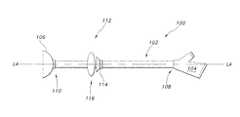
- FIG. 1is a side view illustrating an exemplary enteral feeding tube or “PEG” incorporating an exemplary stoma length indicator assembly.
- FIG. 2is a side view illustrating an exemplary enteral feeding tube or “PEG” incorporating an exemplary stoma length indicator assembly in a compressed configuration.
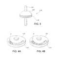
- FIG. 3is a side perspective view illustrating an exemplary stoma length indicator assembly.
- FIGS. 4A and 4Bare a side perspective view illustrations showing a detail of an exemplary stoma length indicator assembly.
- FIGS. 5A and 5Bare a perspective view illustrations showing a detail of another exemplary stoma length indicator assembly.
- FIGS. 6A and 6Bare a perspective view illustrations showing a detail of another exemplary stoma length indicator assembly.
- FIGS. 7A and 7Care perspective views illustrations a detail of another exemplary stoma length indicator assembly.
- FIGS. 7B and 7Dare side cross-section views illustrating a detail of yet another exemplary stoma length indicator assembly.
- FIG. 8is a side cross-section view illustrating a detail of an exemplary stoma length indicator assembly.
- FIG. 9is a side cross-section view illustrating a detail of an exemplary stoma length indicator assembly.
- FIG. 10is a side cross-section view illustrating a detail of an exemplary stoma length indicator assembly.
- FIG. 11is a side cross-section view illustrating a detail of an exemplary stoma length indicator assembly.
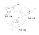
- FIGS. 12A to 12Care perspective view illustrations of a detail of an exemplary image block from an exemplary stoma length indicator assembly.
- FIG. 13is a side cross-section view illustrating an exemplary stoma length indicator assembly.
- FIG. 14is a perspective view illustrating an exemplary stoma length indicator assembly shown in FIG. 13 .
- FIG. 15is an exploded cross-section view illustrating an exemplary stoma length indicator assembly shown in FIG. 13 .
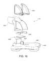
- FIG. 16is an exploded perspective view illustrating an exemplary stoma length indicator assembly.
- the present inventionrelates to an indicator assembly for use with a non-vascular catheter device (e.g. enteral feeding tube, jejunal feeding tube, peritoneal drainage tube, and the like) having a catheter tube, an external retainer (e.g. base deployed outside the human body) and an indwelling retainer which is deployed within a lumen (i.e., a non-vascular lumen or cavity of the body such as, for example, a gastric lumen, jejunum, peritoneal cavity or the like) of the body by insertion through a stoma, and an indicator.
- a lumeni.e., a non-vascular lumen or cavity of the body such as, for example, a gastric lumen, jejunum, peritoneal cavity or the like
- the insertion through the stomamay be from outside the body or it may be performed from inside the body using endoscopic techniques.
- the term “insertion”should be understood as putting in or introducing the catheter tube in place in a stoma so that the base is deployed outside the human body and the indwelling retainer is deployed within a non-vascular lumen or cavity.
- the indicator assemblyaffixed to the exterior of a catheter device (i.e., an enteral feeding tube such as, for example a configurable PEG or “C-PEG” device) and in such configuration, the indicator would be affixed on the skin contacting portion of the C-PEG device.
- the indicator assemblyis a mechanical assembly. That is, it is non-electronic or non-electrical. This ensures simple, reliable operation without the need for batteries complex circuitry, output displays or the like.
- the indicator assemblyensures that the catheter device (e.g., the PEG) does not slide deeper into the patient in the same way that catheter device retention mechanisms (e.g., the PEG's indwelling retainer component) prevent catheter devices from being pulled out of the patient.
- catheter device retention mechanismse.g., the PEG's indwelling retainer component
- the indicator assemblyallows the catheter device tubing to reversibly interlock with it. In some embodiments, the tubing may lock into the indicator assembly and form a 90 degree bend.
- the indicator assemblyhas the ability to be used with a variety of catheter device such as enteral feeding tubes or PEG devices with specific tubing diameters and is not limited to only being used in conjunction with a particular catheter device.
- the indicator assemblyprovides a discrete visual signal (or in some cases, a discrete tactile signal) about the pressure or force drawing the retainers towards the stoma tract. That is, the indicator assembly responds to the pressure generated on the compression of the tissue between the retainer portions of the catheter device. If the catheter device (e.g., enteral feeding tube or other PEG device) encounters a specific pressure (e.g., during an aggressive placement or caused either by manual tightening or through normal growth of the tissue) the indicator assembly provides a discrete visual signal that the pressure or force drawing the retainers toward the stoma tract is different from a predetermined pressure such as, for example, a pressure that is sufficient to deform or collapse the indicator assembly.
- a predetermined pressuresuch as, for example, a pressure that is sufficient to deform or collapse the indicator assembly.
- the non-vascular catheter devicewill be referred to as an enteral feeding tube 100 (which may also be referred to as a “PEG” device) composed of a flexible tube 102 (which may also be referred to as a “catheter” or “shaft”) having walls defining at least one lumen therethrough.
- the PEG device 100also has a base 104 deployed outside the human body and an indwelling retainer 106 (also referred to as “a first retainer” 106 ) which is deployed within a non-vascular lumen or cavity of the body (e.g., a gastric lumen).
- the first retainer 106may be a conventional molded flexible retainer or it may be a configurable retainer that changes from an “insertion” or “removal” state in which the retainer has a diameter that is generally about the same as the tube portion of the PEG device to an expanded “retention” or “deployed” state in which the retainer takes on an expanded mushroom or dome-shape that has a substantially larger diameter than the tube portion of the device.
- Such configurable PEG devicesmay be referred to as C-PEG devices.
- the base 104 of the enteral feeding tube 100has one or more openings allowing access to the lumen(s) of the flexible tube 102 through the base.
- the flexible tube 102has a proximal end 108 and a distal end 110 , a longitudinal axis “LA”, a width and a length.
- the flexible tube 102is desirably positioned through the base 104 in communication with the one or more openings in the base.
- the walls of the flexible tube 102define one or more lumens from the opening(s) in the base to the distal end of the catheter which desirably are in communication with an opening or openings in the first retainer 106 .
- An indicator assembly 112is located on the flexible tube 102 .
- the assembly 112includes the indwelling or first retainer 106 .
- This first retainer 106is secured away from a proximal end 108 of the flexible tube 102 of the enteral feeding tube 100 .
- FIG. 1depicts the first retainer 106 at the distal end 110 of the tube 102 ; however the first retainer 106 can be positioned on tube 102 proximally from the distal end 110 .
- the first retainer 106is deployed within a non-vascular lumen or cavity of the body.
- the indicator assembly 112may also include a second retainer 114 secured on the flexible tube 102 proximal to the first retainer 106 .
- This second retainer 114(if present) is deployed outside the human body.
- An indicator 116is also located on the flexible tube 102 and is configured to be part of the enteral feeding tube 100 that is located outside the body (i.e., against the skin of a patient) between the first retainer 106 and the second retainer 114 . According to an aspect of the invention, a portion of the indicator 116 may be configured to serve as the second retainer 114 as will be discussed later.
- the first retainer 106 and the second retainer 114are configured to maintain substantially the same position with respect to each other on the flexible tube 102 and the indicator 116 is configured to signal a change in position with respect to either the first retainer 106 or the second retainer 114 , thereby indicating a change in the length of a stoma.
- the indicator 116is illustrated under an axial pressure caused by an increase in the length of a stoma (not illustrated) that may result from swelling around the stoma site, infection, weight gain or the like that deforms at least a portion of the indicator.
- the indicatormay flatten and/or expand in a radial direction. As generally illustrated in FIGS.
- the indicator 116may be configured to be positioned at a surface of the skin of the patient and the second retainer 114 may be configured to be positioned above the indicator.
- the second retainer 114may be releasably secured to the tube 102 such that the location of second retainer 114 on the tube may be changed.
- an exemplary indicator 116may include at least a first indicator element 118 and a second indicator element 120 . At least one of the indicator elements 118 , 120 may be configured to be movable and/or deformable with respect to the other to provide a signal.
- the signal provided by the indicatoris desirably a visual signal.
- the indicator 116may include a first indicator element 118 (e.g., a generally flat disc or donut shaped element) adjacent the skin of the wearer and a second indicator element 120 located proximally above the first indicator element 118 (i.e., located in a direction oriented away from the body in the direction of the base 104 ).
- the two indicator elementsare configured to be movable with respect to each other and the second element 120 may be affixed to the catheter or tube component 102 of an enteral feeding device 100 as shown in FIGS. 1 and 2 .
- the second indicator element 120may be releasably affixed to the flexible feeding tube component 102 and the first indicator element 118 may be configured to deform or move relative to the second element 120 .
- the pressure between the second indicator element 120(which may be a base of a PEG device such as, for example, the base of a low-profile feeding tube device) and the first indicator element 118 exceeds a threshold amount, the first element 118 and the second element 120 move relative to each other. This movement results in a change that provides a visual signal—which can be interpreted by the user or caretaker as a change in pressure.
- FIGS. 4A and 4Billustrate how a first indicator element 118 that incorporates at least one disc or other internal component that rotates in response to pressure applied in an axial direction (i.e., along the longitudinal axis LA), with respect to a second indicator element 120 revealing a change in color or pattern to generate a signal indicating a change in the length of a stoma.
- the first indicator element 118may incorporate springs or other conventional components (not shown) that translate movement in an axial direction into rotation of an internal component such as a disc. Different patterns and color combinations may be used to improve the signal contrast.
- a first color or pattern “P”is visible (or the absence of a first color or pattern) and in a second position that is present in response to a change in pressure resulting from a change in the axial dimensions (e.g., length) of a stoma, more of the first color or pattern “P”, or a second color or pattern is visible (or the absence of a first color or pattern).
- a first indicator element 118e.g., in the form of blinds or a lattice-like structure
- Such folding or collapse of the first indicator element 118can provide a change in pattern or color to generate a signal indicating a change in the length of a stoma.
- elastic componentsmay be used between the first and second indicator elements 118 , 120 (e.g., inside a base and top) to provide a restorative rotational force.
- the second indicator element 120located in the proximal direction above the first indicator element 118 ) may rotate relative to the first indicator element 118 to introduce or expose a color and/or pattern “P”, open and/or close a window, or remove or hide a color and/or panel “P”.
- the amount and ease of rotationis dependent on the amount of force applied to the first indictor element 118 .
- Such a configurationmay be used to indicate a removal or absence of pressure against the indicator that may be caused by partial or complete deflation of a balloon retainer, weight loss, and/or reduction in swelling and/or inflammation of a stoma site.
- FIGS. 5A and 5Billustrate an indicator having a second indicator element 120 in the form of a flexible dome top “D” which may be formed of flexible translucent polymers including but not limited to silicones, PVCs (poly-vinyl chloride) or urethanes and a first indicator element 118 in the form of a base “RB” that is relatively much more rigid than the flexible dome top.
- the second indicator element 120e.g., the dome
- the second indicator element 120is affixed, secured or joined to the flexible tube 102 of an enteral feeding tube device 100 (e.g., the second indicator element 120 may be friction fitted to the tube 102 or secured using other conventional techniques).
- first indicator element 118When first indicator element 118 is pushed toward the second indicator element 120 (e.g., by swelling of the stoma site which increases the length of the stoma site), the first indicator element 118 (e.g., the base) is pushed against the second indicator element 120 (e.g., the dome top) and the dome collapses to reveal color or other visual cue 122 that becomes visible through the second indicator element 120 thereby signaling a change in stoma length and/or pressure against the indicator.
- the flexible domemay be composed of a translucent material. Under compression, the dome collapses to reveal a visual signal 122 located on an inner, bottom surface.
- the signalcould consist of or include a variety of graphics, colors, patterns, and messages.
- FIGS. 6A and 6Billustrate an indicator 116 having a second indicator element 120 in the form of a flexible dome top “D” and first indicator element 118 in the form of a rigid base “RB”.
- the second indicator element 120e.g., the dome
- the second indicator element 120is affixed, secured or joined to the flexible tube 102 of an enteral feeding tube device 100 .
- the second indicator element 120e.g., the dome
- the first indicator element 118e.g., the base
- the second indicator element 120collapses pushing visual flags “F” or other indicia out the sides of the device.
- an indicator 116may provide a “disappearing” visual signal in which a flexible first indicator element 118 in the form of a flexible container or tray 200 that is formed from or includes a flexible foam or plastic 202 on a skin contacting side 204 .
- a relatively rigid second indicator element 120 in the form of a clear plate or disk 206is configured to cover or seal with the flexible container or tray 200 (that includes an indicia 208 ) thereby enclosing a generally opaque medium 210 such as a colored water, colored liquid, liquid suspension, gel or other material.
- a generally opaque medium 210such as a colored water, colored liquid, liquid suspension, gel or other material.
- a relatively rigid first indicator element 118may be a hard disk (not shown) that also includes an indicia and a flexible second indicator element 120 may be a separate flexible container or tray (not shown) formed from or includes a clear flexible plastic that seals with the relatively rigid first indicator element 118 to enclose a generally opaque medium 210 such as a colored liquid or gel.
- a generally opaque medium 210such as a colored liquid or gel.
- a relatively opaque medium 210e.g., a colored liquid or gel
- a relatively rigid clear plate or disk 206e.g., upper piece
- a flexible first indicator element 118e.g., bottom piece
- the first indicator element 118is formed such that it has raised or attached indicia 208 such as graphics on an inside surface as illustrated in FIG. 7B .
- the opaque medium 210 contained between the first indicator element 118 and the second indicator element 120must be sufficiently flowable or elastic such that under compression, it is displaced as the first indicator element 118 is deformed, yet still will revert to its uncompressed form after the compression force is removed and the first indicator element returns to its uncompressed form. Compression causes the indicia 208 of the first indicator element 118 to become visible through the opaque medium 210 and provide a signal that is visible through the clear plate or disk 206 that is the second indicator element 120 . Desirably, the indicia are a color that contrasts against the opaque medium.
- Exemplary indicatorsmay also be constructed in which light scattering differences within very soft, flexible materials indicate a change in the length of the stoma tract.
- a second indicator element 120formed of a translucent material, or a relatively transparent material incorporating a patterned or textured surface (which materials may have a first color) may be located directly above a first indicator element 118 that may be in the form of a disk or similar structure having a different color or deeper shade of the same color or dark-colored or patterned surface.
- the different color or deeper shade of the same color or dark-colored or patterned surfacebecomes visible through the translucent material, or a relatively transparent material incorporating a patterned or textured surface (which materials may have a first color) to effectively change its color and provide a signal indicating a change in stoma length.
- FIGS. 8 to 12illustrate other exemplary embodiments of indicators that involve light scattering differences.
- FIG. 8 of the drawingsthere is illustrated an exemplary indicator design that is configured to use pressure against flexible portions of the indicator to generate a visible image. More particularly, the indicator design can be configured to control how incident light is reflected from a surface through the use of a diffusor.
- FIG. 8is a side, cross-sectional illustration of an indicator 300 (which may be a sub-assembly) that includes a transparent or translucent plate 302 that functions as a second indicator element 120 .
- the indicatorincludes a first indicator element 118 in the form of a deformable foot 304 .
- the assemblyalso includes an indicator diffusor 306 .
- the assemblyalso includes an image block 308 which may be a shape block or similar article that is configured to provide an image 310 when it becomes visible through the diffusor 306 and transparent or translucent plate 302 .
- the indicator diffusor 306is a transparent material that has a first surface 312 and a second surface 314 .
- the first surface 312 facing out toward a vieweris flat and smooth.
- incident light beams “LB”will remain relatively unscattered or parallel after passing through the first surface 312 into the diffusor 306 .
- the second surface 314 facing the image block 308has a surface roughness or texture which may be either random or a patterned such that parallel beams of light “LB” traveling from inside the diffusor plate will generally reflect or refract from the diffusor plate surface in non-parallel beams or scattered which effectively diffuses the light.
- the difference between the index of refraction of the diffusor 306 and that of the air (or the medium in the space between the image block and the second surface 314 of the diffusor)also scatters the light such that it is effectively diffused.
- any light that reaches the second surface 314will be scattered in a way that it is relatively diffused.
- the first surface 312 of the diffusor 306will have a uniform appearance and no image of the image bock 308 will be visible through the transparent or translucent plate 302 . That is, a large portion of the light reaching the second surface 314 of the diffusor 306 (which contains a “diffusion” texture) will be reflected in some random orientation due to the texture on the second surface and refraction.
- the compressive force on the deformable foot 304is high enough that the image block 308 is able to make contact with the second surface 314 of the diffusor 306 , the low modulus material of the image block 308 deforms into the texture at the second surface 314 of the diffusor 306 .
- the contact between the image block 308 and the second surface 314 of the diffusor 306alters the diffusion of light due to minimization of index of refraction differences the light encounters.
- the difference between the index of refraction of the diffusor 306 and that of the air (or the medium in the space between the image block and the second surface 314 of the diffusor)is different from the difference between the index of refraction of the diffusor 306 and that of the material of the image block 308 such that more light is transmitted through the second surface 314 of the diffusor rather than reflected or scattered.
- This transmitted lightwill not be reflected back through the diffusor 306 and transparent or translucent plate 302 toward a viewer.
- the two locations “R 1 ” and “R 2 ” on the second surface 314 of the diffusor 306 that are in contact with the shape block 308will generally appear darker than the surrounding diffusor material. This increased contrast makes the image 310 of the shape block 308 visible to the viewer through the transparent or translucent plate 302 .
- the indicator block 308is made from a low modulus material.
- the image block 308is formed in a way that the surface “S” of the block 308 facing the diffusor 306 has a specified shape.
- the shape of the block 308is used to define the indicated image 310 .
- One technique for defining the indicator block shapeis for the indicator block 308 to have a cross-section that defines the image 310 .
- an image block 308 in the form of a cylinderwould have a surface “S” facing the diffusor 306 having a circular cross-section that would create an image 310 of a circle.
- an image block 308may provide one or more surfaces “S” facing the diffusor 306 having one or more shapes (including alphanumeric characters) that would create one or more images 310 .
- FIGS. 12A to 12Cillustrate another technique for generating an image in response to pressure or displacement.
- an image block 308may be a binary or multi-component image block.
- a binary imagemay be composed of a “base” image block 330 formed of a relatively non-deformable material and a relatively deformable “upper” image 332 in the form of a cylinder which is positioned on top of that base image block 330 in the general direction of the arrow “A”.
- no imageis visible through the image plane “PL” as generally represented in FIG. 12B .
- an image 310becomes visible on the image plane PL as illustrated in FIG. 12C .
- FIGS. 13 to 15there is illustrated in side, cross-sectional view ( FIG. 13 ), perspective view ( FIG. 14 ) and exploded side view ( FIG. 15 ), an exemplary and non-limiting embodiment in which the image block 308 is attached to the inner surface of the deformable foot 304 as generally described above but employed in an indicator assembly 112 in which a second retainer 114 has a 90 degree bend to accommodate a low-profile configuration.
- the upper edge 334 of the deformable foot 304is attached to the base of an indicator 116 .
- the indicator 116is pressed down with some force the foot 304 deforms allowing the image block 308 to contact the diffusor 306 .
- the shape and material of the deformable foot 304 and the size of the image block 308will determine the force required to cause the image block 308 to contact the diffusor 306 .
- the indicator 116will show an image when the image block 308 is in contact with the diffusor 306 . This is designed to happen when the distance between the upper surface “S” of the image block 308 and the second surface 314 of the diffusor 306 is smaller. This occurs when there is a compressive force between the two surfaces that brings the upper surface “S” of the image block 308 (usually through deformation of the deformable foot 304 ) and the second surface 314 of the diffusor 306 closer together.
- the indicator assembly 116may be joined or integrated with to a primary support base 400 which can serve as the transparent or translucent plate 302 .
- This base 400can be a variety of shapes and sizes and should define a hole or slot 402 for the feeding tube to fit through.
- An indicator sub-assembly 116(or plurality of sub-assemblies) can be located on the bottom side 404 (side closest to the skin) of the base 400 as illustrated in FIGS. 13 to 15 .
- the indicator 116may be located on the top side 406 of the base 400 as generally illustrated in FIG. 16 .
- an indicator lever 500is visible in a window 502 that sandwiches both sides of a 90 degree bend 504 .
- the base 400 in this embodimentis very flexible and will readily deform causing a post 506 to deflect into a flexible sheet 508 that causes the indicator lever 500 to change from an initial position (e.g., horizontal) to a second position (e.g., vertical) to signal a change in the length of the stoma.
- the basecan be made to have various levels of hardness, ranging from very soft and flexible to completely rigid.
- useful materials of different hardness ratingsinclude (but are not limited to): Water Clear-565 polyurethane (BJB, Hardness 65 Shore A) and Shincor-KE-1950-50 silicone (Shin-Etsu, Hardness 50 Shore A).
- the basemay be made with a transparent or translucent material in order for the indicator to be visible.
- the indicator sub-assemblyis on the top side of the primary support base (e.g., FIG. 16 )
- the baseshould be a soft material, preferably equal to or softer than human tissue.
- the primary support base in such configurationi.e., the indicator sub-assembly is on the top side of the primary support base) can range from transparent to completely opaque.
- the indicator sub-assemblyalso desirably contains a surface component that may be described as a frosted surface or patterned surface of a particular roughness located between the indicator and the field of view for the user.
- This surfacecan either be an integral part of the base (via surface modification to injection molding tooling, for example) or a separate, discreet piece.
- a separate surface componentis a polyester film cut to an appropriate shape.
- the indicator sub-assemblymay further include an indicator shell corresponding to the locations of indication.
- This piececan be any size or shape and can be placed at a variety of locations on the base.
- multiple indicator sub-assembliescan be incorporated into a single device. It is thought that the material selected for the shell of the sub-assembly (or sub-assemblies) depends on the location of the sub-assembly. For devices in which the location of indication (i.e., the location of the sub-assembly) is spaced away from the primary center axis, the indicator shell material hardness should be less than the hardness of the base structure.
- bases constructed with 50 Shore A and 65 Shore A materialsmay be combined with indicator structures (e.g., shells of the indicator sub-assembly) that may be made with both a 10 Shore A and a 15 Shore A material (Smooth-On MoldMax10T Silicone and Smooth-On MoldMax 15T Silicone, respectively).
- indicator structurese.g., shells of the indicator sub-assembly
- the indicator shellshould be a rigid material to provide the indicator a rigid surface to contact upon activation.
- the indicator sub-assemblyalso contains a colored indicator component.
- This componentmay be made of a soft material and have different sizes and shapes.
- An embossed symbol, including letters, numbers, symbols, etc., on the top surfacecan be incorporated to provide a signal.
- the colored indicator componentcan be different colors and should be made with a material softer than the indicator shell. Exemplary materials include silicone materials with a Shore 00 hardness of between 10 and 30.
- the top surface of the colored indicator componentshould be positioned offset from the frosted surface. That gap distance, in addition to material selection, determines the distance and force required to activate the indicator. Once activated, the top surface of the colored indicator makes physical contact with the frosted surface component and the embossed feature becomes visible to the user.
- the present inventionalso encompasses a positioning system for a retainer of a non-vascular catheter device having a catheter tube, an indwelling first retainer which is deployed within a lumen of the body by insertion through a stoma, a second retainer, e.g. a base deployed outside the human body, and an indicator.
- the positioning systemincludes the general structure described above in which a first retainer is fixedly attached to a catheter tube, the first retainer being an indwelling retainer for deployment within a lumen of the body.
- the second retaineris releasably secured to the tube such that the location of second retainer on the tube may be changed.
- An indicator as generally described aboveis located on the tube between the first retainer and the second retainer.
- the indicatoris deployed at a surface of the skin of the patient to provide a placement signal.
- a placement signalis provided by advancing the second retainer toward the first retainer so the indicator generates a placement signal and then retracting the second retainer away from the first retainer so the indicator no longer generates a placement signal.
- the second retainermay be releasably secured to the tube without providing excess pressure on the stoma.
- a repositionable indicator systemfor a catheter tube having a base deployed outside the human body and an indwelling retainer which is deployed within a lumen of the body by insertion through a stoma.
- the repositionable indicator systemhas the structure generally described above and includes an external retainer incorporating a releasable lock to releasably secure the retainer on a catheter tube outside the human body.
- the systemalso includes an indicator as generally described above which is located on the tube, the indicator being configured to be positioned between the skin of a patient and the retainer such that the indicator provides a signal in response to a force applied to the indicator between the skin and the external retainer.
- Yet another aspect of the inventionencompasses a method for positioning an external retainer of a catheter device having a catheter tube, a base as a second retainer deployed outside the human body, an indwelling retainer which is deployed within a lumen of the body by insertion through a stoma, and an indicator.
- the methodgenerally utilizes the indicators and assemblies describe above and includes the steps of: (a) inserting a portion of a catheter tube (e.g., enteral feeding tube, jejunal tube, peritoneal drainage tube or the like) incorporating part of the indicator assembly as generally described above through a stoma to deploy a first retainer within a lumen of the body, for example, a gastric lumen; (b) advancing a second retainer, releasably securable to the tube and deployed outside the human body, towards the first retainer until an indicator deployed at a surface of the skin of the patient provides a placement signal; (c) retracting the second retainer away from the first retainer until the indicator no longer provides a placement signal; and (d) releasably securing the second retainer to the tube.
- a catheter tubee.g., enteral feeding tube, jejunal tube, peritoneal drainage tube or the like
Landscapes
- Health & Medical Sciences (AREA)
- Life Sciences & Earth Sciences (AREA)
- Animal Behavior & Ethology (AREA)
- General Health & Medical Sciences (AREA)
- Public Health (AREA)
- Veterinary Medicine (AREA)
- Heart & Thoracic Surgery (AREA)
- Engineering & Computer Science (AREA)
- Biomedical Technology (AREA)
- Anesthesiology (AREA)
- Hematology (AREA)
- Surgery (AREA)
- Pulmonology (AREA)
- Gastroenterology & Hepatology (AREA)
- Biophysics (AREA)
- Nuclear Medicine, Radiotherapy & Molecular Imaging (AREA)
- Medical Informatics (AREA)
- Molecular Biology (AREA)
- Child & Adolescent Psychology (AREA)
- Pathology (AREA)
- Vascular Medicine (AREA)
- Ophthalmology & Optometry (AREA)
- Media Introduction/Drainage Providing Device (AREA)
- Medical Preparation Storing Or Oral Administration Devices (AREA)
- Surgical Instruments (AREA)
- Endoscopes (AREA)
- Materials For Medical Uses (AREA)
- Infusion, Injection, And Reservoir Apparatuses (AREA)
- Orthopedics, Nursing, And Contraception (AREA)
Abstract
Description
Claims (18)
Priority Applications (12)
| Application Number | Priority Date | Filing Date | Title |
|---|---|---|---|
| US13/245,552US9125800B2 (en) | 2010-09-27 | 2011-09-26 | Stoma length indicator assembly and positioning system |
| CN201180046595.9ACN103189034B (en) | 2010-09-27 | 2011-09-27 | Ostomy length indicator assembly and navigation system |
| CA2811425ACA2811425C (en) | 2010-09-27 | 2011-09-27 | Stoma length indicator assembly and positioning system |
| BR112013007169ABR112013007169A2 (en) | 2010-09-27 | 2011-09-27 | '' Indicator assembly for use with an internal non-vascular catheter device, positioning system, repositionable indicator system, and method for positioning an external retainer '' |
| MX2013003488AMX341777B (en) | 2010-09-27 | 2011-09-27 | Stoma length indicator assembly and positioning system. |
| JP2013529765AJP5977747B2 (en) | 2010-09-27 | 2011-09-27 | Stoma length indicator assembly and positioning system |
| KR1020137007643AKR101835381B1 (en) | 2010-09-27 | 2011-09-27 | Stoma length indicator assembly and positioning system |
| RU2013116382/15ARU2586254C2 (en) | 2010-09-27 | 2011-09-27 | Stoma length indicator and position control system |
| EP11776251.8AEP2621453B1 (en) | 2010-09-27 | 2011-09-27 | Stoma length indicator assembly and positioning system |
| PCT/IB2011/054252WO2012042474A1 (en) | 2010-09-27 | 2011-09-27 | Stoma length indicator assembly and positioning system |
| AU2011309683AAU2011309683B2 (en) | 2010-09-27 | 2011-09-27 | Stoma length indicator assembly and positioning system |
| JP2015236225AJP6127118B2 (en) | 2010-09-27 | 2015-12-03 | Stoma length indicator assembly and positioning system |
Applications Claiming Priority (3)
| Application Number | Priority Date | Filing Date | Title |
|---|---|---|---|
| US38679310P | 2010-09-27 | 2010-09-27 | |
| US201161446229P | 2011-02-24 | 2011-02-24 | |
| US13/245,552US9125800B2 (en) | 2010-09-27 | 2011-09-26 | Stoma length indicator assembly and positioning system |
Publications (2)
| Publication Number | Publication Date |
|---|---|
| US20120078167A1 US20120078167A1 (en) | 2012-03-29 |
| US9125800B2true US9125800B2 (en) | 2015-09-08 |
Family
ID=45871306
Family Applications (5)
| Application Number | Title | Priority Date | Filing Date |
|---|---|---|---|
| US13/245,552Active2033-03-17US9125800B2 (en) | 2010-09-27 | 2011-09-26 | Stoma length indicator assembly and positioning system |
| US13/245,562ActiveUS9339442B2 (en) | 2010-09-27 | 2011-09-26 | Multi-balloon dilation device for placing catheter tubes |
| US13/245,577AbandonedUS20120078039A1 (en) | 2010-09-27 | 2011-09-26 | Dilation Device for Placing Catheter Tubes |
| US13/245,542Active2034-08-09US9211234B2 (en) | 2010-09-27 | 2011-09-26 | Configurable percutaneous endoscopic gastrostomy tube |
| US15/530,336Active2032-11-21US10322067B2 (en) | 2010-09-27 | 2016-10-13 | Dilation device for placing catheter tubes |
Family Applications After (4)
| Application Number | Title | Priority Date | Filing Date |
|---|---|---|---|
| US13/245,562ActiveUS9339442B2 (en) | 2010-09-27 | 2011-09-26 | Multi-balloon dilation device for placing catheter tubes |
| US13/245,577AbandonedUS20120078039A1 (en) | 2010-09-27 | 2011-09-26 | Dilation Device for Placing Catheter Tubes |
| US13/245,542Active2034-08-09US9211234B2 (en) | 2010-09-27 | 2011-09-26 | Configurable percutaneous endoscopic gastrostomy tube |
| US15/530,336Active2032-11-21US10322067B2 (en) | 2010-09-27 | 2016-10-13 | Dilation device for placing catheter tubes |
Country Status (11)
| Country | Link |
|---|---|
| US (5) | US9125800B2 (en) |
| EP (4) | EP2621378B1 (en) |
| JP (5) | JP5830103B2 (en) |
| KR (4) | KR101908933B1 (en) |
| CN (4) | CN103124533B (en) |
| AU (5) | AU2011309685B2 (en) |
| BR (4) | BR112013007168A2 (en) |
| CA (4) | CA2811308C (en) |
| MX (5) | MX2013003336A (en) |
| RU (5) | RU2604042C2 (en) |
| WO (4) | WO2012042473A1 (en) |
Cited By (2)
| Publication number | Priority date | Publication date | Assignee | Title |
|---|---|---|---|---|
| US20160193072A1 (en)* | 2013-08-27 | 2016-07-07 | Jianjiang Lin | Complete flow diversion intestinal ostomy surgery kit |
| US20200137421A1 (en)* | 2018-10-29 | 2020-04-30 | Google Llc | Geometric transforms for image compression |
Families Citing this family (74)
| Publication number | Priority date | Publication date | Assignee | Title |
|---|---|---|---|---|
| MX350734B (en) | 2010-09-08 | 2017-09-15 | Covidien Lp | Catheter with imaging assembly. |
| US9125800B2 (en) | 2010-09-27 | 2015-09-08 | Avent, Inc. | Stoma length indicator assembly and positioning system |
| EP2744445B1 (en)* | 2011-08-20 | 2018-01-31 | Advanced Medical Balloons GmbH | Trans-anal inflow catheter for intermittently triggering a reflex-coordinated defecation |
| US20140066966A1 (en)* | 2012-08-30 | 2014-03-06 | Children's National Medical Center | Endopyloric tool and method to treat hypertropic pyloric stenosis |
| USD735343S1 (en) | 2012-09-07 | 2015-07-28 | Covidien Lp | Console |
| US9517184B2 (en) | 2012-09-07 | 2016-12-13 | Covidien Lp | Feeding tube with insufflation device and related methods therefor |
| USD717340S1 (en) | 2012-09-07 | 2014-11-11 | Covidien Lp | Display screen with enteral feeding icon |
| US9198835B2 (en) | 2012-09-07 | 2015-12-01 | Covidien Lp | Catheter with imaging assembly with placement aid and related methods therefor |
| USD716841S1 (en) | 2012-09-07 | 2014-11-04 | Covidien Lp | Display screen with annotate file icon |
| US9108024B2 (en)* | 2012-09-28 | 2015-08-18 | Avent, Inc. | Retention component for placement of enteral feeding tubes |
| US9492644B2 (en)* | 2012-12-21 | 2016-11-15 | Avent, Inc. | Dilation device for placing catheter tubes |
| US9522253B2 (en)* | 2013-03-13 | 2016-12-20 | Vascular Solutions, Inc. | Drainage or feeding catheter assembly |
| US9833350B2 (en) | 2013-03-15 | 2017-12-05 | Ez-Off Weightloss, Llc | Anchorable size-varying gastric balloons for weight loss |
| EP2967818B1 (en) | 2013-03-15 | 2018-05-16 | Ez Off Weightloss, LLC | System for gastric restriction and malabsorption |
| CN103263280A (en)* | 2013-06-04 | 2013-08-28 | 赵远思 | Intestine stoma fixing device |
| EP3030307B1 (en) | 2013-08-05 | 2019-12-11 | Endo-Tagss, LLC | Transabdominal gastric surgery system |
| US10219799B2 (en) | 2013-08-05 | 2019-03-05 | Endo-Tagss, Llc | Transabdominal gastric device and method |
| BR112016011279B1 (en)* | 2013-11-18 | 2022-09-06 | Halkey-Roberts Corporation | MEDICAL CONNECTOR ASSEMBLY |
| MX369672B (en) | 2013-12-17 | 2019-11-15 | Standard Bariatrics Inc | Resection line guide for a medical procedure and method of using same. |
| AU2015241193B2 (en) | 2014-03-29 | 2020-01-02 | Standard Bariatrics, Inc. | End effectors surgical stapling devices, and methods of using same |
| WO2015153324A1 (en) | 2014-03-29 | 2015-10-08 | Standard Bariatrics, Inc. | End effectors, surgical stapling devices, and methods of using same |
| WO2016037158A1 (en) | 2014-09-05 | 2016-03-10 | Standard Bariatrics, Inc. | Sleeve gastrectomy calibration tube and method of using same |
| US10206595B2 (en)* | 2014-11-17 | 2019-02-19 | 3VO Medical, Inc. | Intrauterine balloon apparatus, system, and method for augmenting uterine birthing forces during parturition |
| CN104606767B (en)* | 2014-11-26 | 2017-12-19 | 潘湘斌 | Foley's tube for ultrasound-guided percutaneous pulmonary valve balloon dilatation |
| WO2016097824A1 (en)* | 2014-12-18 | 2016-06-23 | Evoluzione S.R.L. | Medical device for performing ileostomies and/or jejunostomies |
| US10080874B2 (en) | 2015-04-09 | 2018-09-25 | Boston Scientific Scimed, Inc. | Trap balloon catheter with trap balloon retainer |
| CN107980007B (en)* | 2015-04-09 | 2020-12-11 | 波士顿科学国际有限公司 | Capture balloon catheter with capture balloon retainer |
| US9808282B2 (en)* | 2015-06-04 | 2017-11-07 | Medos International Sarl | Surgical cannula system and method of use |
| US10285837B1 (en) | 2015-09-16 | 2019-05-14 | Standard Bariatrics, Inc. | Systems and methods for measuring volume of potential sleeve in a sleeve gastrectomy |
| KR101725235B1 (en)* | 2015-12-01 | 2017-04-11 | 충남대학교산학협력단 | Surgical Trocar |
| CN106182730B (en)* | 2016-07-28 | 2018-10-16 | 七星电气股份有限公司 | A kind of expansion mold for cool condensing electric cable accessories |
| WO2018034658A1 (en)* | 2016-08-17 | 2018-02-22 | Avent, Inc. | Enteral feeding satiation device |
| WO2018067690A1 (en) | 2016-10-04 | 2018-04-12 | Ez-Off Weight Loss, Llc | Sleeve-anchorable gastric balloon for weight loss |
| CN109843152B (en)* | 2016-10-14 | 2022-02-25 | M·D·诺亚 | Balloon structure with anchoring portion for anchoring in body passage |
| WO2018150219A1 (en)* | 2017-02-16 | 2018-08-23 | N.V. Nutricia | Gastrostomy device with an improved retaining element |
| CN110678159A (en)* | 2017-02-16 | 2020-01-10 | 纽崔西亚公司 | Gastrostomy device with pressure monitoring |
| JP6995869B2 (en)* | 2017-02-23 | 2022-01-17 | ボストン サイエンティフィック サイムド,インコーポレイテッド | Mounting equipment used with medical equipment |
| CN107174315B (en)* | 2017-05-04 | 2019-10-11 | 温州市人民医院 | Peritoneo-puncture needle fixes device |
| CN107348976B (en)* | 2017-05-19 | 2019-11-19 | 薛运章 | A kind of mesenterium support device and method for supporting |
| US11338112B2 (en) | 2017-07-03 | 2022-05-24 | Cathaid, Inc. | Devices for monitoring movement of a secured catheter during a procedure |
| US10912562B2 (en) | 2017-08-14 | 2021-02-09 | Standard Bariatrics, Inc. | End effectors, surgical stapling devices, and methods of using same |
| RU2691924C1 (en)* | 2017-12-25 | 2019-06-18 | Арчил Зурабович Цулая | Method for gastrostomy using polypropylene mesh |
| KR101984878B1 (en) | 2018-01-10 | 2019-05-31 | 강석진 | Dry edible Materials pulverization machine |
| CN112930208A (en) | 2018-06-01 | 2021-06-08 | 恩多Rx有限责任公司 | Dilation device and method of use thereof |
| EP3856308B1 (en)* | 2018-09-27 | 2025-08-13 | Coloplast A/S | Tracheostoma device holder |
| CN114126516A (en)* | 2018-11-30 | 2022-03-01 | 快管医疗有限责任公司 | Method and device for the treatment of tension pneumothorax using a rapidly deployable thoracic port |
| CN109700525A (en)* | 2018-12-28 | 2019-05-03 | 先健科技(深圳)有限公司 | Stoma instrument |
| US11666696B2 (en) | 2019-03-25 | 2023-06-06 | Ellen McGrath | Enterostomy drainage methods and devices |
| USD896365S1 (en)* | 2019-06-24 | 2020-09-15 | Mark Sipe | Medical port disc |
| CN211856471U (en) | 2019-08-22 | 2020-11-03 | 贝克顿·迪金森公司 | Quantitative testing system for echogenicity of echogenic medical instrument |
| KR102049701B1 (en)* | 2019-08-22 | 2020-01-08 | 이지희 | A liquid medicine injection machine Of Balloon type |
| CN211884905U (en) | 2019-08-22 | 2020-11-10 | 贝克顿·迪金森公司 | Balloon dilatation catheter and balloon thereof |
| CN112401971B (en) | 2019-08-23 | 2025-09-09 | 贝克顿·迪金森公司 | Stone extraction for percutaneous nephroscope surgical design kit |
| CN110801312A (en)* | 2019-10-21 | 2020-02-18 | 复旦大学附属中山医院 | Intervene valve release stop device |
| BR112022008009A2 (en) | 2019-11-04 | 2022-07-12 | Standard Bariatrics Inc | SYSTEMS AND METHODS OF PERFORMING SURGERY USING LAPLACE'S LAW TENSION RETRACTION DURING SURGERY |
| US12274635B2 (en) | 2019-11-04 | 2025-04-15 | Standard Bariatrics, Inc. | Systems and methods of performing surgery using laplace's law tension retraction during surgery |
| CN111375121B (en)* | 2020-03-18 | 2022-05-17 | 南京鼓楼医院 | Nerve block sleeve assembly |
| JP2021154089A (en)* | 2020-03-30 | 2021-10-07 | テルモ株式会社 | Transfistula tube device |
| CN111450392B (en)* | 2020-05-11 | 2025-01-14 | 上海市东方医院(同济大学附属东方医院) | Multi-level fistula dilatation puncture drainage tube with balloon |
| CN115955943A (en) | 2020-06-30 | 2023-04-11 | 标准肥胖病研究公司 | Systems, devices, and methods for preventing or reducing insufflation loss during laparoscopic procedures |
| CN111840754A (en)* | 2020-08-17 | 2020-10-30 | 安卓医疗技术(山东)有限公司 | An internal fixation device for a pipe and a method of using the same |
| CN112245772B (en)* | 2020-10-19 | 2022-05-06 | 四川大学华西医院 | Monitoring regulation and control device of adjustable two sacs three chambeies intraductal air pressure |
| AU2022242751B2 (en) | 2021-03-23 | 2024-05-02 | Standard Bariatrics, Inc. | Systems and methods for preventing tissue migration in surgical staplers |
| CN113244502B (en)* | 2021-04-20 | 2025-04-29 | 青岛博泰医疗器械有限责任公司 | Visualized pressure regulating catheter |
| CN113576578B (en)* | 2021-07-29 | 2022-09-13 | 宿州微腾企业管理咨询服务有限公司 | Intracardiac branch of academic or vocational study hemostasis constriction device |
| KR102597188B1 (en) | 2021-08-20 | 2023-11-02 | 주식회사 파인메딕스 | Gastrostomy Tube Kit |
| CN113941074B (en)* | 2021-11-12 | 2024-05-24 | 北京大学深圳医院 | Pharyngeal expansion device for gastroscopy of elderly patients |
| CN114099912B (en)* | 2021-11-18 | 2024-03-22 | 南京脉创医疗科技有限公司 | Intracranial balloon dilation catheter |
| TWI773597B (en)* | 2021-11-25 | 2022-08-01 | 長庚學校財團法人長庚科技大學 | Guided operation and detection device for gastrostomy care |
| CN114082086B (en)* | 2021-12-23 | 2024-03-29 | 赛诺神畅医疗科技有限公司 | Balloon guiding catheter |
| CN114159009A (en)* | 2021-12-31 | 2022-03-11 | 上海博方医疗科技有限公司 | Capsule endoscope system and operation method |
| CN115814244B (en)* | 2022-12-30 | 2025-09-23 | 中国人民解放军总医院第八医学中心 | Coronary artery delivery catheter and delivery device for cardiac interventional therapy |
| CN116899036A (en)* | 2023-08-08 | 2023-10-20 | 首都医科大学附属北京朝阳医院 | Drainage device |
| KR20250121771A (en)* | 2024-02-05 | 2025-08-12 | 부산대학교 산학협력단 | Hemostatic Bronchoscope Balloon Device for Forward Viewing with Simultaneous Blood Suction |
Citations (24)
| Publication number | Priority date | Publication date | Assignee | Title |
|---|---|---|---|---|
| US4972845A (en) | 1989-01-05 | 1990-11-27 | Abbott Laboratories | Stoma measuring device |
| US5092850A (en) | 1990-11-29 | 1992-03-03 | Buma Shelley J | Catheter with adjustable external locking bolster |
| WO1993008729A1 (en) | 1991-11-06 | 1993-05-13 | Inbae Yoon | Surgical instrument stabilizer |
| EP0615740A1 (en) | 1993-01-15 | 1994-09-21 | Sandoz Nutrition Ltd. | Gastrostomy feeding port with elastic adjustable tip |
| US5484420A (en) | 1992-07-09 | 1996-01-16 | Wilson-Cook Medical Inc. | Retention bolsters for percutaneous catheters |
| US5860952A (en) | 1996-01-11 | 1999-01-19 | C. R. Bard, Inc. | Corporeal access tube assembly and method |
| US5891113A (en)* | 1996-01-11 | 1999-04-06 | C. R. Bard, Inc. | Corporeal access tube assembly |
| US6030361A (en) | 1999-01-25 | 2000-02-29 | Miyashiro; Augusto M. | Gastrostomy apparatus |
| US6231547B1 (en) | 1999-02-18 | 2001-05-15 | Abbott Laboratories | External retaining device for a catheter and catheter assembly and method using same |
| US6231549B1 (en) | 1999-08-17 | 2001-05-15 | Sherwood Services, Ag | Shim device for enteral feeding system |
| US6494848B1 (en) | 1996-12-19 | 2002-12-17 | St. Jude Medical Puerto Rico B.V. | Measuring device for use with a hemostatic puncture closure device |
| US20030212349A1 (en) | 2002-05-08 | 2003-11-13 | Meier Kevin C. | Stoma measuring device |
| US6666853B2 (en) | 2002-03-27 | 2003-12-23 | Scimed Life Systems, Inc. | Low profile adaptor for use with a medical catheter |
| US20040116868A1 (en)* | 2000-12-19 | 2004-06-17 | Forman Michael Robert | Intra-pericardial drug delivery device with multiple-balloons and method for angiogenesis |
| US20070005086A1 (en)* | 2005-06-21 | 2007-01-04 | Gresham Richard D | Adjustable trocar washer |
| WO2008005496A2 (en) | 2006-07-05 | 2008-01-10 | Aspiration Medical Technology, Llc | Shunt apparatus for treating obesity by extracting food |
| WO2008019082A2 (en) | 2006-08-03 | 2008-02-14 | Aspiration Medical Technology, Llc | Systems and methods for removing ingested material from a stomach |
| WO2008027375A2 (en) | 2006-08-31 | 2008-03-06 | Cook Incorporated | Rotationally actuated fixation mechanism |
| WO2008157172A1 (en) | 2007-06-12 | 2008-12-24 | Bristol-Myers Squibb Company | Ostomy appliance |
| US7582072B2 (en) | 2004-09-09 | 2009-09-01 | Kimberly-Clark Worldwide, Inc. | Artificial stoma and method of use |
| WO2009155537A1 (en) | 2008-06-19 | 2009-12-23 | Bristol-Myers Squibb Company | Ostomy appliances for directing effluent output |
| US20100057013A1 (en) | 2005-04-21 | 2010-03-04 | Tyco Healthcare Group Lp | Intracorporeal indwelling equipment |
| WO2010115102A1 (en) | 2009-04-02 | 2010-10-07 | Radius International Limited Partnership | Low profile and tension monitoring external peg bolster |
| US20110009828A1 (en)* | 2009-07-07 | 2011-01-13 | C.R.Bard, Inc. | Extensible internal bolster for a medical device |
Family Cites Families (101)
| Publication number | Priority date | Publication date | Assignee | Title |
|---|---|---|---|---|
| US3397699A (en) | 1966-05-05 | 1968-08-20 | Gerald C. Kohl | Retaining catheter having resiliently biased wing flanges |
| US3633579A (en) | 1967-05-24 | 1972-01-11 | Sherwood Medical Ind Inc | Catheter placement device and method |
| US3915171A (en) | 1974-06-06 | 1975-10-28 | Dennis William Shermeta | Gastrostomy tube |
| US4315513A (en) | 1980-03-10 | 1982-02-16 | Nawash Michael S | Gastrostomy and other percutaneous transport tubes |
| US4393873A (en) | 1980-03-10 | 1983-07-19 | Nawash Michael S | Gastrostomy and other percutaneous transport tubes |
| US4531943A (en) | 1983-08-08 | 1985-07-30 | Angiomedics Corporation | Catheter with soft deformable tip |
| US4627838A (en) | 1983-12-09 | 1986-12-09 | Bard Limited | Stylet actuated winged catheter |
| US4758219A (en) | 1985-05-17 | 1988-07-19 | Microvasive, Inc. | Enteral feeding device |
| US4763654A (en)* | 1986-09-10 | 1988-08-16 | Jang G David | Tandem independently inflatable/deflatable multiple diameter balloon angioplasty catheter systems and method of use |
| US4850953A (en) | 1987-07-27 | 1989-07-25 | Habley Medical Technology Corporation | Gastrostomy valve |
| US4861334A (en) | 1988-06-24 | 1989-08-29 | Nawaz Arain | Self-retaining gastrostomy tube |
| US4944732A (en) | 1988-08-15 | 1990-07-31 | Sandoz Nutrition Corporation | Gastrostomy feeding port |
| JPH0249547U (en)* | 1988-09-30 | 1990-04-06 | ||
| US5073166A (en) | 1989-02-15 | 1991-12-17 | Medical Innovations Corporation | Method and apparatus for emplacement of a gastrostomy catheter |
| US5374254A (en) | 1990-11-29 | 1994-12-20 | Buma; Shelley J. | Catheters with adjustable external locking bolsters |
| US5112310A (en) | 1991-02-06 | 1992-05-12 | Grobe James L | Apparatus and methods for percutaneous endoscopic gastrostomy |
| US5356391A (en) | 1992-06-22 | 1994-10-18 | Medical Innovations Corp. | Flexible retainer flange for gastrostomy tube and the method of installing it |
| US5248302A (en) | 1992-08-05 | 1993-09-28 | Biosearch Medical Products Inc. | Percutaneous obturatable internal anchoring device |
| US5702365A (en)* | 1992-09-08 | 1997-12-30 | King; Toby St. John | Daul-lumen catheter |
| EP0683684B1 (en) | 1993-01-07 | 2001-08-08 | Medical Innovations Corporation | Gastrostomy catheter system |
| US5336203A (en) | 1993-05-28 | 1994-08-09 | Abbott Laboratories | Low profile gastrostomy device with dome |
| US5505698A (en)* | 1993-10-29 | 1996-04-09 | Medtronic, Inc. | Cardioplegia catheter with elongated cuff |
| US5429598A (en) | 1994-04-19 | 1995-07-04 | Applied Medical Resources Corporation | Surgical access device and procedure |
| US6036673A (en)* | 1996-01-11 | 2000-03-14 | C. R. Bard, Inc. | Bolster for corporeal access tube assembly |
| US6019746A (en) | 1996-05-17 | 2000-02-01 | Applied Medical Technology, Inc. | Low profile balloon feeding device |
| DE19634116C2 (en) | 1996-08-23 | 1998-08-20 | Fresenius Ag | Catheter for percutaneous enteral nutrition |
| US6293924B1 (en)* | 1996-12-12 | 2001-09-25 | Advanced Cardiovascular Systems, Inc. | Balloon assembly with separately inflatable sections |
| NL1005068C2 (en) | 1997-01-23 | 1998-07-27 | Ct Rrn Academisch Ziekenhuis U | Catheter system and a catheter forming part thereof. |
| SE9700373L (en)* | 1997-02-04 | 1998-07-13 | Stig Bengmark | Probe for providing fluid communication with the small intestine |
| US5928260A (en) | 1997-07-10 | 1999-07-27 | Scimed Life Systems, Inc. | Removable occlusion system for aneurysm neck |
| US6077250A (en) | 1997-10-01 | 2000-06-20 | Boston Scientific Corporation | Apparatus and method for percutaneously placing gastrostomy tubes |
| US6186985B1 (en) | 1997-10-03 | 2001-02-13 | Boston Scientific Corporation | Gastro-intestinal tube with dissolvable support bolster |
| US6464686B1 (en)* | 1998-01-21 | 2002-10-15 | Abbott Laboratories | Polyurethane feeding tube and associated adaptors |
| US6364858B1 (en) | 1998-03-31 | 2002-04-02 | Applied Medical Research, Inc. | Collapsible internal bolster for gastrostomy device |
| US6039714A (en) | 1998-05-12 | 2000-03-21 | Novartis Nutrition Ag | Collapsible retention bolster for gastrostomy and other ostomy tubes |
| US6527748B1 (en) | 1998-08-17 | 2003-03-04 | Yutaka Suzuki | Method of gastrostomy, and an infection preventive cover, kit or catheter kit, and a gastrostomy catheter kit |
| EP1674125B1 (en)* | 1998-08-17 | 2009-04-29 | Yutaka Suzuki | A method of gastrostomy and an infection preventive cover and a gastrostomy catheter kit |
| US6030406A (en) | 1998-10-05 | 2000-02-29 | Origin Medsystems, Inc. | Method and apparatus for tissue dissection |
| US6322538B1 (en) | 1999-02-18 | 2001-11-27 | Scimed Life Systems, Inc. | Gastro-intestinal tube placement device |
| US20050085771A1 (en)* | 1999-04-16 | 2005-04-21 | Lyon Thomas R. | Clear view cannula |
| US6881420B2 (en) | 2000-06-23 | 2005-04-19 | Teva Pharmaceutical Industries Ltd. | Compositions and dosage forms for gastric delivery of irinotecan and methods of treatment that use it to inhibit cancer cell proliferation |
| ITBO20000511A1 (en) | 2000-09-05 | 2002-03-05 | Gianmario Monza | APPARATUS AND METHOD FOR THE CONSTRUCTION OF GASTROSTOMY |
| US6743207B2 (en)* | 2001-04-19 | 2004-06-01 | Scimed Life Systems, Inc. | Apparatus and method for the insertion of a medical device |
| WO2002103409A2 (en) | 2001-06-19 | 2002-12-27 | The Trustees Of The University Of Pennsylvania | Optical guidance system for invasive catheter placement |
| DE10139644B4 (en) | 2001-08-11 | 2004-04-01 | Fresenius Kabi Deutschland Gmbh | Mounting part for an adapter of a PEG probe and adapter for a PEG probe with such a mounting part |
| US7736336B2 (en) | 2001-09-13 | 2010-06-15 | Allegiance Corporation | Paracentesis device having multiple detachable components |
| US7137993B2 (en)* | 2001-12-03 | 2006-11-21 | Xtent, Inc. | Apparatus and methods for delivery of multiple distributed stents |
| US6896665B2 (en) | 2001-12-10 | 2005-05-24 | Applied Medical Research | Gastrostomy device package and method of assembly |
| US20030163114A1 (en) | 2002-02-26 | 2003-08-28 | Gershowitz Arthur D. | Retrograde cannula having manually retractable sealing member |
| JP4351458B2 (en) | 2002-03-18 | 2009-10-28 | オリンパス株式会社 | Endoscope insertion system |
| US7083595B2 (en) | 2002-05-01 | 2006-08-01 | Scimed Lipe Systems, Inc. | Medical catheter assembly and method of using the same |
| JP2004099584A (en) | 2002-05-02 | 2004-04-02 | Keio Gijuku | Anti-tumor agent using HSV |
| US6878130B2 (en)* | 2002-05-28 | 2005-04-12 | Sherwood Services Ag | External inflation indicator for a low profile gastrostomy tube |
| US20030225392A1 (en) | 2002-05-31 | 2003-12-04 | Kimberly-Clark Worldwide, Inc. | Low profile transpyloric jejunostomy system and method to enable |
| AU2003258124A1 (en) | 2002-08-05 | 2004-02-23 | Miravant Medical Technologies | Light delivery catheter |
| US6942641B2 (en) | 2003-05-30 | 2005-09-13 | J. Michael Seddon | Catheter |
| WO2004112877A1 (en) | 2003-06-20 | 2004-12-29 | Ranier Limited | A medical device |
| WO2004112879A1 (en)* | 2003-06-20 | 2004-12-29 | Coloplast A/S | A medical device comprising a braided portion |
| US7220252B2 (en)* | 2003-07-18 | 2007-05-22 | Polyzen, Inc. | Inflatable dual balloon catheter |
| US20070203445A1 (en)* | 2004-02-26 | 2007-08-30 | V-Kardia Pty Ltd | Isolating cardiac circulation |
| US7462175B2 (en)* | 2004-04-21 | 2008-12-09 | Acclarent, Inc. | Devices, systems and methods for treating disorders of the ear, nose and throat |
| JP4588356B2 (en)* | 2004-04-30 | 2010-12-01 | 日本シャーウッド株式会社 | Gastrostomy tube extender |
| JP4623548B2 (en)* | 2004-04-30 | 2011-02-02 | 日本シャーウッド株式会社 | Gastrostomy tube extender |
| US7654980B2 (en) | 2004-05-14 | 2010-02-02 | Boston Scientific Scimed, Inc. | Method for percutaneously implanting a medical catheter and medical catheter implanting assembly |
| US20060030818A1 (en) | 2004-08-09 | 2006-02-09 | Mcvey Robert D | System and method for securing a medical access device |
| US20080039715A1 (en) | 2004-11-04 | 2008-02-14 | Wilson David F | Three-dimensional optical guidance for catheter placement |
| US20060270989A1 (en)* | 2005-05-27 | 2006-11-30 | Mcmichael Donald J | Gastric fastening system |
| GB2428198A (en) | 2005-07-11 | 2007-01-24 | Stavros Michael Stivaros | A self-retaining surgical tube |
| US8954134B2 (en) | 2005-09-13 | 2015-02-10 | Children's Medical Center Corporation | Light-guided transluminal catheter |
| US8709018B2 (en) | 2005-09-16 | 2014-04-29 | Applied Medical Technology, Inc. | Non-balloon low profile feed device with insertion/removal tool |
| JP2007167082A (en)* | 2005-12-19 | 2007-07-05 | Michiaki Kudo | Guide instrument of in-vivo insertion tube via gastric fistula and instrument kit for changing percutaneous gastrostoma-tube to jejunum tube via gastric fistula |
| US7740609B2 (en)* | 2006-03-03 | 2010-06-22 | Boston Scientific Scimed, Inc. | Balloon catheter |
| US7771396B2 (en) | 2006-03-22 | 2010-08-10 | Ethicon Endo-Surgery, Inc. | Intubation device for enteral feeding |
| US20070255222A1 (en) | 2006-03-27 | 2007-11-01 | Changqing Li | Catheter assembly including internal bolster |
| US20070239171A1 (en) | 2006-03-30 | 2007-10-11 | Ethicon Endo-Surgery, Inc. | Medical snaring device |
| US20070233005A1 (en)* | 2006-04-03 | 2007-10-04 | Mcmichael Donald J | Surgical fastening tool |
| US8551043B2 (en)* | 2006-04-21 | 2013-10-08 | C. R. Bard, Inc. | Feeding device and bolster apparatus and method for making the same |
| FR2904531B1 (en) | 2006-08-02 | 2009-06-12 | Eleph Ent Technology | PERCUTANEOUS GASTROSTOMY PROBE |
| US7547303B2 (en) | 2006-08-03 | 2009-06-16 | Boston Scientific Scimed, Inc. | Catheter assembly including foldable internal bolster |
| EP2080242A4 (en)* | 2006-09-25 | 2013-10-30 | Valentx Inc | Toposcopic access and delivery devices |
| JP2008099917A (en) | 2006-10-19 | 2008-05-01 | Goodman Co Ltd | Catheter indeflator |
| US8414611B2 (en)* | 2006-11-03 | 2013-04-09 | Boston Scientific Scimed, Inc. | Main vessel constraining side-branch access balloon |
| EP2120839A2 (en) | 2007-03-14 | 2009-11-25 | Kathryn A. Mckenzie Waitzman | Methods and systems for locating a feeding tube inside of a patient |
| US9078997B2 (en) | 2007-03-29 | 2015-07-14 | Boston Scientific Scimed, Inc. | Catheter assembly including coiled internal bolster |
| EP2155082B1 (en) | 2007-05-17 | 2012-06-20 | Boston Scientific Scimed, Inc. | Tissue securing and sealing apparatus |
| US8211136B2 (en)* | 2007-08-31 | 2012-07-03 | Kimberly-Clark Worldwide, Inc. | Stoma dilator |
| US20090281379A1 (en)* | 2008-05-12 | 2009-11-12 | Xlumena, Inc. | System and method for transluminal access |
| US20090318757A1 (en) | 2008-06-23 | 2009-12-24 | Percuvision, Llc | Flexible visually directed medical intubation instrument and method |
| WO2010008793A1 (en) | 2008-06-23 | 2010-01-21 | Percuvision, Llc | Flexible visually directed medical intubation instrument and method |
| US20090318873A1 (en) | 2008-06-24 | 2009-12-24 | Cook Incorporated | Medical malecot with magnets |
| US9107810B2 (en) | 2008-06-24 | 2015-08-18 | Cook Medical Technologies Llc | Gastric port system |
| DE102008037916A1 (en) | 2008-08-14 | 2010-02-18 | Fresenius Kabi Deutschland Gmbh | Device for creating a percutaneous endoscopic gastrostomy |
| BRPI0919195A2 (en)* | 2008-09-18 | 2019-09-24 | Acclarent Inc | Methods and Apparatus for the Treatment of Ear, Nose, and Throat Disorders |
| US20100087706A1 (en) | 2008-09-30 | 2010-04-08 | Intrapace, Inc. | Lead Access |
| US20100081991A1 (en)* | 2008-09-30 | 2010-04-01 | Tyco Healthcare Group Lp | Skin level device for use with gastrostomy tube |
| WO2010075032A2 (en) | 2008-12-22 | 2010-07-01 | Cook Incorporated | Low-profile external fitting |
| US8252057B2 (en)* | 2009-01-30 | 2012-08-28 | Ethicon Endo-Surgery, Inc. | Surgical access device |
| WO2011053242A1 (en) | 2009-10-29 | 2011-05-05 | Ah San Pang | A spacer and a method of using the same |
| WO2011159590A2 (en) | 2010-06-14 | 2011-12-22 | The General Hospital Corporation | Stricture treatment and drainage catheter |
| US9125800B2 (en) | 2010-09-27 | 2015-09-08 | Avent, Inc. | Stoma length indicator assembly and positioning system |
| US9108024B2 (en)* | 2012-09-28 | 2015-08-18 | Avent, Inc. | Retention component for placement of enteral feeding tubes |
- 2011
- 2011-09-26USUS13/245,552patent/US9125800B2/enactiveActive
- 2011-09-26USUS13/245,562patent/US9339442B2/enactiveActive
- 2011-09-26USUS13/245,577patent/US20120078039A1/ennot_activeAbandoned
- 2011-09-26USUS13/245,542patent/US9211234B2/enactiveActive
- 2011-09-27AUAU2011309685Apatent/AU2011309685B2/enactiveActive
- 2011-09-27MXMX2013003336Apatent/MX2013003336A/enactiveIP Right Grant
- 2011-09-27CACA2811308Apatent/CA2811308C/enactiveActive
- 2011-09-27WOPCT/IB2011/054251patent/WO2012042473A1/enactiveApplication Filing
- 2011-09-27KRKR1020137007495Apatent/KR101908933B1/ennot_activeExpired - Fee Related
- 2011-09-27CACA2811425Apatent/CA2811425C/enactiveActive
- 2011-09-27CNCN201180046593.XApatent/CN103124533B/ennot_activeExpired - Fee Related
- 2011-09-27CNCN201180045973.1Apatent/CN103298421B/ennot_activeExpired - Fee Related
- 2011-09-27WOPCT/IB2011/054253patent/WO2012042475A1/enactiveApplication Filing
- 2011-09-27BRBR112013007168Apatent/BR112013007168A2/ennot_activeApplication Discontinuation
- 2011-09-27MXMX2013003485Apatent/MX2013003485A/ennot_activeApplication Discontinuation
- 2011-09-27RURU2013116380/14Apatent/RU2604042C2/ennot_activeIP Right Cessation
- 2011-09-27EPEP11776543.8Apatent/EP2621378B1/enactiveActive
- 2011-09-27JPJP2013529764Apatent/JP5830103B2/ennot_activeExpired - Fee Related
- 2011-09-27MXMX2013003487Apatent/MX342252B/enactiveIP Right Grant
- 2011-09-27KRKR1020137006363Apatent/KR101841949B1/ennot_activeExpired - Fee Related
- 2011-09-27JPJP2013529766Apatent/JP5834081B2/enactiveActive
- 2011-09-27BRBR112013007169Apatent/BR112013007169A2/ennot_activeApplication Discontinuation
- 2011-09-27CNCN201180046595.9Apatent/CN103189034B/ennot_activeExpired - Fee Related
- 2011-09-27RURU2013116382/15Apatent/RU2586254C2/ennot_activeIP Right Cessation
- 2011-09-27BRBR112013007171-0Apatent/BR112013007171A2/ennot_activeIP Right Cessation
- 2011-09-27EPEP11776887.9Apatent/EP2621379B1/ennot_activeNot-in-force
- 2011-09-27KRKR1020137006482Apatent/KR20130138204A/ennot_activeCeased
- 2011-09-27JPJP2013529767Apatent/JP6042336B2/enactiveActive
- 2011-09-27MXMX2016009389Apatent/MX353296B/enunknown
- 2011-09-27EPEP20110776542patent/EP2621454B1/ennot_activeNot-in-force
- 2011-09-27AUAU2011309683Apatent/AU2011309683B2/enactiveActive
- 2011-09-27WOPCT/IB2011/054254patent/WO2012042476A1/enactiveApplication Filing
- 2011-09-27RURU2013116381/14Apatent/RU2600278C2/ennot_activeIP Right Cessation
- 2011-09-27CACA2811246Apatent/CA2811246A1/ennot_activeAbandoned
- 2011-09-27BRBR112013007170Apatent/BR112013007170A2/ennot_activeApplication Discontinuation
- 2011-09-27MXMX2013003488Apatent/MX341777B/enactiveIP Right Grant
- 2011-09-27WOPCT/IB2011/054252patent/WO2012042474A1/enactiveApplication Filing
- 2011-09-27RURU2013116379/15Apatent/RU2589686C2/ennot_activeIP Right Cessation
- 2011-09-27CACA2812720Apatent/CA2812720C/enactiveActive
- 2011-09-27EPEP11776251.8Apatent/EP2621453B1/enactiveActive
- 2011-09-27CNCN201180046599.7Apatent/CN103124548B/ennot_activeExpired - Fee Related
- 2011-09-27KRKR1020137007643Apatent/KR101835381B1/ennot_activeExpired - Fee Related
- 2011-09-27JPJP2013529765Apatent/JP5977747B2/enactiveActive
- 2011-09-27AUAU2011309682Apatent/AU2011309682B2/ennot_activeCeased
- 2011-09-27AUAU2011309684Apatent/AU2011309684B2/ennot_activeCeased
- 2011-09-27RURU2016136325Apatent/RU2016136325A/ennot_activeApplication Discontinuation
- 2015
- 2015-12-03JPJP2015236225Apatent/JP6127118B2/ennot_activeExpired - Fee Related
- 2016
- 2016-02-03AUAU2016200661Apatent/AU2016200661B2/enactiveActive
- 2016-10-13USUS15/530,336patent/US10322067B2/enactiveActive
Patent Citations (28)
| Publication number | Priority date | Publication date | Assignee | Title |
|---|---|---|---|---|
| US4972845A (en) | 1989-01-05 | 1990-11-27 | Abbott Laboratories | Stoma measuring device |
| US5092850A (en) | 1990-11-29 | 1992-03-03 | Buma Shelley J | Catheter with adjustable external locking bolster |
| WO1993008729A1 (en) | 1991-11-06 | 1993-05-13 | Inbae Yoon | Surgical instrument stabilizer |
| US5484420A (en) | 1992-07-09 | 1996-01-16 | Wilson-Cook Medical Inc. | Retention bolsters for percutaneous catheters |
| EP0615740A1 (en) | 1993-01-15 | 1994-09-21 | Sandoz Nutrition Ltd. | Gastrostomy feeding port with elastic adjustable tip |
| US5413565A (en) | 1993-01-15 | 1995-05-09 | Sandoz Nutrition Ltd. | Gastrostomy feeding port with elastic adjustable tip |
| US5860952A (en) | 1996-01-11 | 1999-01-19 | C. R. Bard, Inc. | Corporeal access tube assembly and method |
| US5891113A (en)* | 1996-01-11 | 1999-04-06 | C. R. Bard, Inc. | Corporeal access tube assembly |
| US6494848B1 (en) | 1996-12-19 | 2002-12-17 | St. Jude Medical Puerto Rico B.V. | Measuring device for use with a hemostatic puncture closure device |
| US6030361A (en) | 1999-01-25 | 2000-02-29 | Miyashiro; Augusto M. | Gastrostomy apparatus |
| US6231547B1 (en) | 1999-02-18 | 2001-05-15 | Abbott Laboratories | External retaining device for a catheter and catheter assembly and method using same |
| US6231549B1 (en) | 1999-08-17 | 2001-05-15 | Sherwood Services, Ag | Shim device for enteral feeding system |
| US20040116868A1 (en)* | 2000-12-19 | 2004-06-17 | Forman Michael Robert | Intra-pericardial drug delivery device with multiple-balloons and method for angiogenesis |
| US6666853B2 (en) | 2002-03-27 | 2003-12-23 | Scimed Life Systems, Inc. | Low profile adaptor for use with a medical catheter |
| US20030212349A1 (en) | 2002-05-08 | 2003-11-13 | Meier Kevin C. | Stoma measuring device |
| US6764453B2 (en) | 2002-05-08 | 2004-07-20 | Sherwood Services Ag | Stoma measuring device |
| US7582072B2 (en) | 2004-09-09 | 2009-09-01 | Kimberly-Clark Worldwide, Inc. | Artificial stoma and method of use |
| US20100057013A1 (en) | 2005-04-21 | 2010-03-04 | Tyco Healthcare Group Lp | Intracorporeal indwelling equipment |
| US20070005086A1 (en)* | 2005-06-21 | 2007-01-04 | Gresham Richard D | Adjustable trocar washer |
| US20080091146A1 (en) | 2006-07-05 | 2008-04-17 | Aspiration Medical Technology, Llc | Shunt apparatus for treating obesity by extracting food |
| WO2008005496A2 (en) | 2006-07-05 | 2008-01-10 | Aspiration Medical Technology, Llc | Shunt apparatus for treating obesity by extracting food |
| WO2008019082A2 (en) | 2006-08-03 | 2008-02-14 | Aspiration Medical Technology, Llc | Systems and methods for removing ingested material from a stomach |
| US7648479B2 (en) | 2006-08-03 | 2010-01-19 | Deka Products Limited Partnership | Systems and methods for removing ingested material from a stomach |
| WO2008027375A2 (en) | 2006-08-31 | 2008-03-06 | Cook Incorporated | Rotationally actuated fixation mechanism |
| WO2008157172A1 (en) | 2007-06-12 | 2008-12-24 | Bristol-Myers Squibb Company | Ostomy appliance |
| WO2009155537A1 (en) | 2008-06-19 | 2009-12-23 | Bristol-Myers Squibb Company | Ostomy appliances for directing effluent output |
| WO2010115102A1 (en) | 2009-04-02 | 2010-10-07 | Radius International Limited Partnership | Low profile and tension monitoring external peg bolster |
| US20110009828A1 (en)* | 2009-07-07 | 2011-01-13 | C.R.Bard, Inc. | Extensible internal bolster for a medical device |
Cited By (4)
| Publication number | Priority date | Publication date | Assignee | Title |
|---|---|---|---|---|
| US20160193072A1 (en)* | 2013-08-27 | 2016-07-07 | Jianjiang Lin | Complete flow diversion intestinal ostomy surgery kit |
| US10188542B2 (en)* | 2013-08-27 | 2019-01-29 | Jianjiang Lin | Complete flow diversion intestinal ostomy surgery kit |
| US20200137421A1 (en)* | 2018-10-29 | 2020-04-30 | Google Llc | Geometric transforms for image compression |
| US11412260B2 (en)* | 2018-10-29 | 2022-08-09 | Google Llc | Geometric transforms for image compression |
Also Published As
Similar Documents
| Publication | Publication Date | Title |
|---|---|---|
| US9125800B2 (en) | Stoma length indicator assembly and positioning system | |
| CA2505010C (en) | Catheter with unitary component | |
| US4863438A (en) | Low profile gastrostomy device | |
| US8523818B2 (en) | Enteral feeding assembly with obturator | |
| ES2589779T3 (en) | Enteral nutrition catheter set that incorporates an indicator | |
| MXPA05005226A (en) | Gastric balloon catheter with improved balloon orientation. | |
| CA2656626A1 (en) | Shunt apparatus for treating obesity by extracting food | |
| US20110082442A1 (en) | Externally reinforced percutaneous gastrostomy tube with customizable smooth tube length | |
| US20040106901A1 (en) | Catheter having a balloon member invertedly attached thereto | |
| EP1433494B1 (en) | Esophagus stoma button | |
| CA2544569A1 (en) | Venting catheter | |
| WO2011031679A1 (en) | Externally reinforced percutaneous gastrostomy tube with customizable smooth tube length |
Legal Events
| Date | Code | Title | Description |
|---|---|---|---|
| AS | Assignment | Owner name:KIMBERLY-CLARK WORLDWIDE, INC., WISCONSIN Free format text:ASSIGNMENT OF ASSIGNORS INTEREST;ASSIGNORS:BAKER, ANDREW T.;STADELMAN, JENNIFER S.;JACKSON, DWAYNE J-K;AND OTHERS;SIGNING DATES FROM 20111109 TO 20111212;REEL/FRAME:027796/0602 | |
| AS | Assignment | Owner name:AVENT, INC., GEORGIA Free format text:ASSIGNMENT OF ASSIGNORS INTEREST;ASSIGNOR:KIMBERLY-CLARK WORLDWIDE, INC.;REEL/FRAME:034182/0208 Effective date:20141030 | |
| AS | Assignment | Owner name:MORGAN STANLEY SENIOR FUNDING, INC., NEW YORK Free format text:SECURITY INTEREST;ASSIGNOR:AVENT, INC.;REEL/FRAME:035375/0867 Effective date:20150227 | |
| STCF | Information on status: patent grant | Free format text:PATENTED CASE | |
| AS | Assignment | Owner name:CITIBANK, N.A., NEW YORK Free format text:INTELLECTUAL PROPERTY SECURITY INTEREST ASSIGNMENT AGREEMENT;ASSIGNOR:MORGAN STANLEY SENIOR FUNDING, INC.;REEL/FRAME:048173/0137 Effective date:20181029 | |
| FEPP | Fee payment procedure | Free format text:SURCHARGE FOR LATE PAYMENT, LARGE ENTITY (ORIGINAL EVENT CODE: M1554); ENTITY STATUS OF PATENT OWNER: LARGE ENTITY | |
| MAFP | Maintenance fee payment | Free format text:PAYMENT OF MAINTENANCE FEE, 4TH YEAR, LARGE ENTITY (ORIGINAL EVENT CODE: M1551); ENTITY STATUS OF PATENT OWNER: LARGE ENTITY Year of fee payment:4 | |
| AS | Assignment | Owner name:JPMORGAN CHASE BANK, N.A., AS ADMINISTRATIVE AGENT, ILLINOIS Free format text:SECURITY INTEREST;ASSIGNOR:AVENT, INC.;REEL/FRAME:060441/0445 Effective date:20220624 | |
| AS | Assignment | Owner name:AVANOS MEDICAL SALES, LLC, GEORGIA Free format text:RELEASE BY SECURED PARTY;ASSIGNOR:CITIBANK, N.A.;REEL/FRAME:060557/0062 Effective date:20220624 Owner name:AVENT, INC., GEORGIA Free format text:RELEASE BY SECURED PARTY;ASSIGNOR:CITIBANK, N.A.;REEL/FRAME:060557/0062 Effective date:20220624 | |
| MAFP | Maintenance fee payment | Free format text:PAYMENT OF MAINTENANCE FEE, 8TH YEAR, LARGE ENTITY (ORIGINAL EVENT CODE: M1552); ENTITY STATUS OF PATENT OWNER: LARGE ENTITY Year of fee payment:8 |