US9125767B2 - Wound filler having dynamic motion - Google Patents
Wound filler having dynamic motionDownload PDFInfo
- Publication number
- US9125767B2 US9125767B2US13/714,119US201213714119AUS9125767B2US 9125767 B2US9125767 B2US 9125767B2US 201213714119 AUS201213714119 AUS 201213714119AUS 9125767 B2US9125767 B2US 9125767B2
- Authority
- US
- United States
- Prior art keywords
- strand
- wound filler
- nodes
- charged state
- state
- Prior art date
- Legal status (The legal status is an assumption and is not a legal conclusion. Google has not performed a legal analysis and makes no representation as to the accuracy of the status listed.)
- Expired - Fee Related, expires
Links
Images


Classifications
- A—HUMAN NECESSITIES
- A61—MEDICAL OR VETERINARY SCIENCE; HYGIENE
- A61F—FILTERS IMPLANTABLE INTO BLOOD VESSELS; PROSTHESES; DEVICES PROVIDING PATENCY TO, OR PREVENTING COLLAPSING OF, TUBULAR STRUCTURES OF THE BODY, e.g. STENTS; ORTHOPAEDIC, NURSING OR CONTRACEPTIVE DEVICES; FOMENTATION; TREATMENT OR PROTECTION OF EYES OR EARS; BANDAGES, DRESSINGS OR ABSORBENT PADS; FIRST-AID KITS
- A61F13/00—Bandages or dressings; Absorbent pads
- A61F13/05—Bandages or dressings; Absorbent pads specially adapted for use with sub-pressure or over-pressure therapy, wound drainage or wound irrigation, e.g. for use with negative-pressure wound therapy [NPWT]
- A61F13/00068—
- A61F13/00008—
- A—HUMAN NECESSITIES
- A61—MEDICAL OR VETERINARY SCIENCE; HYGIENE
- A61F—FILTERS IMPLANTABLE INTO BLOOD VESSELS; PROSTHESES; DEVICES PROVIDING PATENCY TO, OR PREVENTING COLLAPSING OF, TUBULAR STRUCTURES OF THE BODY, e.g. STENTS; ORTHOPAEDIC, NURSING OR CONTRACEPTIVE DEVICES; FOMENTATION; TREATMENT OR PROTECTION OF EYES OR EARS; BANDAGES, DRESSINGS OR ABSORBENT PADS; FIRST-AID KITS
- A61F13/00—Bandages or dressings; Absorbent pads
- A61F13/01—Non-adhesive bandages or dressings
- A61F13/01008—Non-adhesive bandages or dressings characterised by the material
- A—HUMAN NECESSITIES
- A61—MEDICAL OR VETERINARY SCIENCE; HYGIENE
- A61L—METHODS OR APPARATUS FOR STERILISING MATERIALS OR OBJECTS IN GENERAL; DISINFECTION, STERILISATION OR DEODORISATION OF AIR; CHEMICAL ASPECTS OF BANDAGES, DRESSINGS, ABSORBENT PADS OR SURGICAL ARTICLES; MATERIALS FOR BANDAGES, DRESSINGS, ABSORBENT PADS OR SURGICAL ARTICLES
- A61L15/00—Chemical aspects of, or use of materials for, bandages, dressings or absorbent pads
- A61L15/16—Bandages, dressings or absorbent pads for physiological fluids such as urine or blood, e.g. sanitary towels, tampons
- A61L15/42—Use of materials characterised by their function or physical properties
- A—HUMAN NECESSITIES
- A61—MEDICAL OR VETERINARY SCIENCE; HYGIENE
- A61F—FILTERS IMPLANTABLE INTO BLOOD VESSELS; PROSTHESES; DEVICES PROVIDING PATENCY TO, OR PREVENTING COLLAPSING OF, TUBULAR STRUCTURES OF THE BODY, e.g. STENTS; ORTHOPAEDIC, NURSING OR CONTRACEPTIVE DEVICES; FOMENTATION; TREATMENT OR PROTECTION OF EYES OR EARS; BANDAGES, DRESSINGS OR ABSORBENT PADS; FIRST-AID KITS
- A61F13/00—Bandages or dressings; Absorbent pads
- A61F2013/00089—Wound bandages
- A61F2013/0017—Wound bandages possibility of applying fluid
- A61F2013/00174—Wound bandages possibility of applying fluid possibility of applying pressure
- A—HUMAN NECESSITIES
- A61—MEDICAL OR VETERINARY SCIENCE; HYGIENE
- A61F—FILTERS IMPLANTABLE INTO BLOOD VESSELS; PROSTHESES; DEVICES PROVIDING PATENCY TO, OR PREVENTING COLLAPSING OF, TUBULAR STRUCTURES OF THE BODY, e.g. STENTS; ORTHOPAEDIC, NURSING OR CONTRACEPTIVE DEVICES; FOMENTATION; TREATMENT OR PROTECTION OF EYES OR EARS; BANDAGES, DRESSINGS OR ABSORBENT PADS; FIRST-AID KITS
- A61F13/00—Bandages or dressings; Absorbent pads
- A61F2013/00089—Wound bandages
- A61F2013/00238—Wound bandages characterised by way of knitting or weaving
- A—HUMAN NECESSITIES
- A61—MEDICAL OR VETERINARY SCIENCE; HYGIENE
- A61F—FILTERS IMPLANTABLE INTO BLOOD VESSELS; PROSTHESES; DEVICES PROVIDING PATENCY TO, OR PREVENTING COLLAPSING OF, TUBULAR STRUCTURES OF THE BODY, e.g. STENTS; ORTHOPAEDIC, NURSING OR CONTRACEPTIVE DEVICES; FOMENTATION; TREATMENT OR PROTECTION OF EYES OR EARS; BANDAGES, DRESSINGS OR ABSORBENT PADS; FIRST-AID KITS
- A61F13/00—Bandages or dressings; Absorbent pads
- A61F2013/00089—Wound bandages
- A61F2013/0028—Wound bandages applying of mechanical pressure; passive massage
- A—HUMAN NECESSITIES
- A61—MEDICAL OR VETERINARY SCIENCE; HYGIENE
- A61F—FILTERS IMPLANTABLE INTO BLOOD VESSELS; PROSTHESES; DEVICES PROVIDING PATENCY TO, OR PREVENTING COLLAPSING OF, TUBULAR STRUCTURES OF THE BODY, e.g. STENTS; ORTHOPAEDIC, NURSING OR CONTRACEPTIVE DEVICES; FOMENTATION; TREATMENT OR PROTECTION OF EYES OR EARS; BANDAGES, DRESSINGS OR ABSORBENT PADS; FIRST-AID KITS
- A61F13/00—Bandages or dressings; Absorbent pads
- A61F2013/00361—Plasters
- A61F2013/00365—Plasters use
- A61F2013/00536—Plasters use for draining or irrigating wounds
- A—HUMAN NECESSITIES
- A61—MEDICAL OR VETERINARY SCIENCE; HYGIENE
- A61F—FILTERS IMPLANTABLE INTO BLOOD VESSELS; PROSTHESES; DEVICES PROVIDING PATENCY TO, OR PREVENTING COLLAPSING OF, TUBULAR STRUCTURES OF THE BODY, e.g. STENTS; ORTHOPAEDIC, NURSING OR CONTRACEPTIVE DEVICES; FOMENTATION; TREATMENT OR PROTECTION OF EYES OR EARS; BANDAGES, DRESSINGS OR ABSORBENT PADS; FIRST-AID KITS
- A61F13/00—Bandages or dressings; Absorbent pads
- A61F2013/00361—Plasters
- A61F2013/00544—Plasters form or structure
- A61F2013/00548—Plasters form or structure net
- A—HUMAN NECESSITIES
- A61—MEDICAL OR VETERINARY SCIENCE; HYGIENE
- A61F—FILTERS IMPLANTABLE INTO BLOOD VESSELS; PROSTHESES; DEVICES PROVIDING PATENCY TO, OR PREVENTING COLLAPSING OF, TUBULAR STRUCTURES OF THE BODY, e.g. STENTS; ORTHOPAEDIC, NURSING OR CONTRACEPTIVE DEVICES; FOMENTATION; TREATMENT OR PROTECTION OF EYES OR EARS; BANDAGES, DRESSINGS OR ABSORBENT PADS; FIRST-AID KITS
- A61F13/00—Bandages or dressings; Absorbent pads
- A61F2013/00361—Plasters
- A61F2013/00902—Plasters containing means
- A61F2013/00919—Plasters containing means for physical therapy, e.g. cold or magnetic
Definitions
- the subject matter of this specificationrelates generally to reduced pressure treatment systems and more particularly, but not by way of limitation, to a wound filler having dynamic motion.
- reduced pressureis applied by a reduced pressure source to tissue through a porous pad or other manifold device.
- the porous padcontains cells or pores that are capable of distributing reduced pressure to the tissue and channeling fluids that are drawn from the tissue.
- the porous padoften is incorporated into a dressing having other components that facilitate treatment.
- a wound filler for positioning adjacent a wound site on a patientincludes at least one strand having a plurality of nodes positioned along a length of the strand.
- the strandhas a charged state and an uncharged state. In the charged state, the strand includes a stored energy that when released would deform or move the strand. In the discharged state, the stored energy has been released.
- the wound fillerfurther includes a removable sheath encasing the strand. The strand can transition from the charged state to the uncharged state as the removable sheath is removed.
- a wound filler for positioning adjacent a wound site on a patient for treating the wound site with reduced pressureincludes a first strand having a plurality of nodes positioned along a length of the first strand, a second strand having a plurality of nodes positioned along a length of the second strand, and rods connecting the first strand to the second strand.
- a dissolvable membranesurrounds the first strand and the second strand.
- the wound fillerhas a charged state in which the first and second strands include a stored energy that when released would deform or move the plurality of nodes on the first and second strands, and an uncharged state in which the stored energy has been released.
- the wound fillercan transition from the charged state to the uncharged state as the membrane softens in the presence of wound fluid. The transition is configured to dynamically change the position of the plurality of nodes against the wound site.
- a wound filler for positioning adjacent a wound site on a patient for treating the wound site with reduced pressureincludes a web having a plurality of nodes positioned on the web, and a removable membrane fitted around the web such that a shape of the plurality of nodes is visible.
- the membraneholds the web in a first, potential energy state that when released would deform or move the plurality of nodes.
- the webgradually transitions into a second, resting state as the membrane dissolves in the presence of wound fluid.
- a system for treating a wound site on a patient with reduced pressureincludes a wound filler.
- the wound fillerincludes at least one strand having a plurality of nodes positioned along a length of the strand.
- the strandhas a charged state and an uncharged state. In the charged state, the strand includes a stored energy that when released would deform or move the strand. In the discharged state, the stored energy has been released.
- the wound fillerfurther includes a removable sheath encasing the strand. The strand transitions from the charged state to the uncharged state as the removable sheath is removed.
- the systemfurther includes a drape positioned over the wound filler and capable of attaching to an intact portion of the patient's epidermis for creating a sealed space beneath the drape and a reduced pressure source for supplying reduced pressure to the sealed space.
- a system for treating a wound site on a patient with reduced pressureincludes a wound filler.
- the wound fillerincludes a first strand having a plurality of nodes positioned along a length of the first strand, a second strand having a plurality of nodes positioned along a length of the second strand, and rods connecting the first strand to the second strand.
- a dissolvable membranesurrounds the first strand and the second strand.
- the wound fillerhas a charged state in which the first and second strands include a stored energy that when released would deform or move the plurality of nodes on the first and second strands, and an uncharged state in which the stored energy has been released.
- the wound fillertransitions from the charged state to the uncharged state as the membrane softens in the presence of wound fluid.
- the transitionis configured to dynamically change the position of the plurality of nodes against the wound site.
- the systemfurther includes a drape positioned over the wound filler and capable of attaching to an intact portion of the patient's epidermis for creating a sealed space beneath the drape and a reduced pressure source for supplying reduced pressure to the sealed space.
- a system for treating a wound site on a patient with reduced pressureincludes a wound filler.
- the wound fillerincludes a web having a plurality of nodes positioned on the web, and a removable membrane fitted around the web such that a shape of the plurality of nodes are visible.
- the membraneholds the web in a potential energy state that when released would deform or move the plurality of nodes.
- the webgradually transitions into a resting state as the membrane dissolves in the presence of wound fluid.
- the systemfurther includes a drape positioned over the wound filler and capable of attaching to an intact portion of the patient's epidermis for creating a sealed space beneath the drape and a reduced pressure source for supplying reduced pressure to the sealed space.
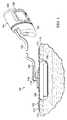
- FIG. 1illustrates a perspective view, with a portion shown in cross-section, of a reduced pressure treatment system, including a wound filler according to an illustrative embodiment
- FIG. 2illustrates an embodiment of a wound filler in a first, charged state, having a sheath and an interior portion shown with hidden lines, for use with the reduced pressure treatment system illustrated in FIG. 1 ;
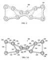
- FIG. 3Aillustrates the wound filler of FIG. 2 without the sheath in the first, charged state
- FIG. 3Billustrates the wound filler of FIG. 2 without the sheath in the second, uncharged state
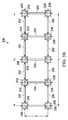
- FIG. 4Aillustrates another embodiment of a wound filler in a first state
- FIG. 4Billustrates the wound filler of FIG. 4A in a second state
- FIG. 5illustrates an embodiment of the wound filler of FIGS. 4A and 4B having a sheath for use with the reduced pressure treatment system illustrated in FIG. 1 ;
- FIG. 6illustrates another embodiment of the wound filler of FIGS. 4A and 4B having a sheath for use with the reduced pressure treatment system illustrated in FIG. 1 ;
- FIG. 7illustrates another embodiment of a wound filler for use with the reduced pressure treatment system illustrated in FIG. 1 ;
- FIG. 8illustrates another embodiment of a wound filler for use with the reduced pressure treatment system illustrated in FIG. 1 .
- reduced pressuregenerally refers to a pressure less than the ambient pressure at a tissue site that is being subjected to treatment. In most cases, this reduced pressure will be less than the atmospheric pressure at which the patient is located. Alternatively, the reduced pressure may be less than a hydrostatic pressure associated with tissue at the tissue site.
- vacuumand “negative pressure” may be used to describe the pressure applied to the tissue site, the actual pressure reduction applied to the tissue site may be significantly less than the pressure reduction normally associated with a complete vacuum.
- Reduced pressuremay initially generate fluid flow in the area of the tissue site As the hydrostatic pressure around the tissue site approaches the desired reduced pressure, the flow may subside, and the reduced pressure is then maintained. Unless otherwise indicated, values of pressure stated herein are gauge pressures. Similarly, references to increases in reduced pressure typically refer to a decrease in absolute pressure, while decreases in reduced pressure typically refer to an increase in absolute pressure.
- static wound fillers used in long duration applicationsi.e., wound fillers used for three or more days
- the wound filleris later removed, there is the risk that some of the newly formed tissue will be removed with the wound filler, or portions of the wound filler will remain at the tissue site
- static wound fillers used in long duration applicationsmay expose portions of the tissue site to microstrains for too long a period of time When portions of the tissue site are exposed to microstrains for too long a period of time, the higher stress areas may not be able to form new granulation tissue. The result may be a wound bed with a mixture of very high granulation zones and zones of no granulation formation.
- the tissue treatment systems and apparatuses described hereincan improve the treatment of a tissue site by providing a wound filler having dynamic motion that is used in conjunction with reduced pressure treatment.
- the wound fillerincludes a plurality of nodes that expose the tissue site to micro-mechanical stresses and strains.
- the wound fillerhas a first, charged state, in which the wound filler stores energy in the form of potential energy that when released moves the plurality of nodes.
- the wound filleralso has a second, resting state, in which the stored energy has been released.
- the wound fillergradually transitions from the first state to the second state. As the wound filler transitions, the plurality of nodes move across the wound site creating microstrain at the tissue site.
- the plurality of nodestransmit a force to the tissue site where the nodes contact the tissue site.
- This forcemay be referred to as a point load.
- the force distribution of the plurality of nodes across the tissue siteresults in a particular microstrain distribution, which varies based on the force distribution and the rate at which the wound filler transitions between the first state and the second state. Since microstrain at the tissue site assists in the development of new granulation tissue, it is beneficial to vary the distribution of force and microstrain during treatment such that a more even development of granulation tissue is obtained.
- tissue sitemay refer to a wound or defect located on or within any tissue, including but not limited to, bone tissue, adipose tissue, muscle tissue, neural tissue, dermal tissue, vascular tissue, connective tissue, cartilage, tendons, or ligaments.
- tissue sitemay further refer to areas of any tissue that are not necessarily wounded or defective, but are instead areas in which it is desired to add or promote the growth of additional tissue. For example, reduced pressure tissue treatment may be used in certain tissue areas to grow additional tissue that may be harvested and transplanted to another tissue location.
- the dressing 103is configured to promote growth of new tissue at the tissue site 102 and includes a wound filler 108 positioned adjacent to, or in some embodiments, in contact with, the tissue site 102 .
- the dressing 103may further include a cover or drape 110 positioned over the wound filler 108 to secure the wound filler 108 at the tissue site 102 and to seal a space that is located beneath the cover and that is at least partially occupied by the wound filler 108 .
- the drape 110contains the wound filler 108 at the tissue site 102 as the wound filler 108 transitions from the charged state to the resting state.
- the drape 110extends beyond a perimeter of the tissue site 102 and is placed either in contact with or otherwise in proximity to a patient's epidermis 112 to create a fluid seal between the drape 110 and the epidermis 112 .
- the drape 110may include an adhesive 114 or bonding agent to secure the drape 110 to the epidermis 112 .
- the adhesive 114may be used to create a seal between the drape 110 and the epidermis 112 to prevent leakage of reduced pressure from the tissue site 102 .
- a seal layersuch as, for example, a hydrogel or other material may be disposed between the drape 110 and the epidermis 112 to augment or substitute for the sealing properties of the adhesive 114 .
- fluid sealmeans a seal adequate to maintain reduced pressure at a desired site given the particular reduced pressure source involved and the particular treatment desired.
- the drape 110 and the bonding characteristics of the drape 110provide sealing sufficient to prevent leakage greater than 0.5 L/min at 125 mmHg reduced pressure.
- the dressing 103may further include a reduced pressure interface 116 in fluid communication with the space beneath the drape 110 .
- the interface 116may be positioned adjacent to or coupled to the drape 110 to provide fluid access to the wound filler 108 and the tissue site 102 .
- the drape 110includes an aperture 118 for providing fluid access to the interface 116 .
- a conduit 120fluidly couples the therapy unit 104 and the interface 116 .
- the interface 116is capable of delivering reduced pressure to the tissue site 102 .
- the therapy unit 104includes a fluid containment member 122 in fluid communication with a reduced pressure source 124 .
- the fluid containment member 122is a collection canister that includes a chamber for collecting fluids from the tissue site 102 .
- the fluid containment member 122alternatively could be an absorbent material or any other container, device, or material that is capable of collecting fluid.
- the conduit 120may be a multi-lumen tube having one or more conduits to deliver reduced pressure to the dressing 103 and one or more conduits to sense the amount of pressure at the tissue site 102 . Liquids or exudates communicated from the wound filler 108 through the conduit 120 are removed from the conduit 120 and retained within the fluid containment member 122 .
- the reduced pressure source 124may be an electrically driven vacuum pump. In another implementation, the reduced pressure source 124 instead may be a manually-actuated or manually-charged pump that does not require electrical power. In one embodiment, the reduced pressure source 124 may be one or more piezoelectric-actuated micropumps that may be positioned remotely from the dressing 103 , or at the dressing beneath or adjacent to the drape 110 . The reduced pressure source 124 instead may be any other type of pump, or alternatively, a wall suction port or air delivery port such as those available in hospitals and other medical facilities.
- the reduced pressure source 124may be housed within or used in conjunction with the therapy unit 104 , which may also contain sensors, processing units, alarm indicators, memory, databases, software, display units, and user interfaces 126 that further facilitate the application of reduced pressure treatment to the tissue site 102 .
- pressure-detection sensors(not shown) may be disposed at or near the reduced pressure source 124 .
- the pressure-detection sensorsmay receive pressure data from the interface 116 via lumens in the conduit 120 that are dedicated to delivering reduced pressure data to the pressure-detection sensors.
- the pressure-detection sensorsmay communicate with a processing unit that monitors and controls the reduced pressure that is delivered by the reduced pressure source 124 .
- the wound filler 208is positioned adjacent to, or in some embodiments, in contact with, the tissue site 102 .
- the wound filler 208creates point loads at the tissue site 102 where the wound filler 208 contacts the tissue site 102 . These point loads cause micro-mechanical stresses and strains at the tissue site 102 .
- the wound filler 208is configured to move against and relative to the tissue site 102 .
- the wound filler 208has a first, or charged, state in which the wound filler 208 includes a stored energy that when released deforms or moves the wound filler 208 .
- the stored energymay be in the form of potential energy.
- the wound filler 208also has a second, or discharged, state in which the stored energy has been released and the wound filler 208 is at rest.
- FIG. 3Ashows one embodiment of the wound filler 208 in the charged state
- FIG. 3Bshows the wound filler 208 in the uncharged state.
- the energy stored in the wound filler 208enables the wound filler 208 to move against the tissue site 102 during therapy without the need for an external energy source or interaction.
- the wound filler 208is configured to transition from the charged state to the discharged state irrespective of reduced pressure acting on the wound filler 208 .
- the wound filler 208is further configured to allow for fluid flow to and from the tissue site 102 while manifolding or distributing the reduced pressure to the tissue site 102 .
- the mechanisms for transitioning the wound filler 208 from the charged state to the discharged statewill be discussed in more detail below.
- the transition of the wound filler 208 from the charged state to the discharged statecauses the wound filler 208 to move against and relative to the tissue site 102 .
- portions of the tissue site 102 exposed to the movement path of the wound filler 208are exposed to micro-mechanical stresses and strains, thereby creating a particular micro-strain distribution across the tissue site 102 .
- the micro-mechanical stresses and strains at the tissue site 102assist in the development of new granulation tissue.
- moving the location of the point loads, the point loads being caused by the wound filler 208creates a more even distribution of new granulation tissue than static wound fillers for at least two reasons.
- the wound filler 208includes a first strand 230 and a second strand 232 . While the wound filler 208 is shown as having the first strand 230 and the second strand 232 , it should be appreciated that the wound filler 208 may only have one strand, or the wound filler 208 may include a plurality of strands.
- the first strand 230is connected to the second strand 232 by a plurality of struts or rods 234 .
- the first and second strands 230 , 232 as well as the plurality of rods 234may be formed from a woven or non-woven material or fabric. In one embodiment, the first and second strands 230 , 232 and the plurality of rods 234 may be comprised of fibers.
- the first and second strands 230 , 232 and the plurality of rods 234may also be formed from a number of different materials, including polymers such as polyester, polyamide, polyethylene, polyurethane, and thermoplastic elastomers. Further, the first and the second strands 230 , 232 and the plurality of rods 234 may be formed of silicone, or metals such as stainless steel. The first and the second strands 230 , 232 and the plurality of rods 234 may be made from only polymers, only metals, or a combination of polymers and metals. The material or material combination may be varied to provide a range of hard to soft options.
- the material used to form at least the first strand 230 , the second strand 232 , and the plurality of rods 234is resilient so that when the first strand 230 , the second strand 232 , and the plurality of rods 234 are twisted or deformed, the first strand 230 , the second strand 232 , and the plurality of rods 234 will return to their resting state without permanent deformation.
- potential energyis created within the first strand 230 , the second strand 232 , and the plurality of rods 234 .
- first strand 230 , the second strand 232 , and the plurality of rods 234when the first strand 230 , the second strand 232 , and the plurality of rods 234 are deformed, internal forces act to restore the first strand 230 , the second strand 232 , and the plurality of rods 234 to their resting state.
- the first strand 230 , the second strand 232 , and the plurality of rods 234may be twisted or deformed from their resting state when they are adjacent the tissue site 102 by patient movement, flexing at the tissue site 102 , forces from the drape, and the periodic release of the reduced pressure at the tissue site 102 .
- the first strand 230 , the second strand 232 , and the plurality of rods 234are positioned adjacent the tissue site 102 in the charged state. Over a certain time period, the first strand 230 , the second strand 232 , and the plurality of rods 234 transition into the uncharged state. Patient movement, flexing at the tissue site 102 , forces from the drape, and the periodic release of the reduced pressure at the tissue may twist or deform the first strand 230 , the second strand 232 , and the plurality of rods 234 , creating internal forces within the first strand 230 , the second strand 232 , and the plurality of rods 234 . The internal forces act to restore the first strand 230 , the second strand 232 , and the plurality of rods 234 to their resting state.
- the wound filler 208may further include a membrane or sheath 244 that surrounds, covers, or encases the first strand 230 , the second strand 232 , and the plurality of rods 234 .
- the first strand 230 , the second strand 232 , and the plurality of rods 234may be held in the charged state by the membrane or sheath 244 .
- the membrane or sheath 244may be a coating applied to the first strand 230 , the second strand 232 , and the plurality of rods 234 .
- the first strand 230 , the second strand 232 , and the plurality of rods 234may sometimes be referred to as the inner portion of the wound filler 208 whereas the sheath 244 or coating may be referred to as the outer portion of the wound filler 208 .
- the sheath 244may hold or help hold the first and second strands 230 , 232 and the plurality of rods 234 in the charged state.
- the sheath 244is configured to be removed from the first strand 230 , the second strand 232 , and the plurality of rods 234 . Removal of the sheath 244 causes the wound filler 208 to transition from the first, charged state to the second, uncharged state.
- the sheath 244may be physically removed by a healthcare provider.
- the sheath 244may be formed from a water soluble cover, or a water soluble coating.
- the water soluble cover and the water soluble coatingmay be formed from a polyvinyl alcohol and its copolymers, carboxyl and hydroxyl substituted acrylics and salts, polyethylene glycols, polyvinyl pyrrolidones, carboxymethycellulose and its salts, and sugars.
- the sheathis bioabsorbable and dissolves in the presence of fluid such as a wound fluid.
- the material used to form the sheath 244may be chosen based on the rate to dissolution of the material. The rate to dissolution may be from less than one hour up to several days.
- the rate to dissolutionmay be 1 hour, 3 hours, 12 hours, 24 hours, 2 days, 3 days, or more.
- the ability of the sheath 244 to hold the first strand 230 , the second strand 232 , and the plurality of rods 234 in the charged stateweakens.
- the first strand 230 , the second strand 232 , and the plurality of rods 234may gradually transition from the charged state to the uncharged state over a period of time as the potential energy stored in the first strand 230 , the second strand 232 , and the plurality of rods 234 is released.
- the time period over which the first strand 230 , the second strand 232 , and the plurality of rods 234 transition from the charged state to the uncharged statedepends on the material properties of the chosen sheath 244 , e.g., the material's rate to dissolution.
- the internal forces acting on the first strand 230 , the second strand 232 , and the plurality of rods 234i.e., the forces acting to release the stored potential energy and return to the resting state, begin to overcome the force of the sheath 244 , i.e., the force acting on the first strand 230 , the second strand 232 , and the plurality of rods 234 to stay in the charged state.
- the sheath 244may soften but not dissolve in the presence of fluid.
- the softening of the sheath 244allows the internal forces of the first strand 230 , the second strand 232 , and the plurality of rods 234 to overcome the force of the sheath holding the first strand 230 , the second strand 232 , and the plurality of rods 234 in the first, charged state.
- the internal forces of the first strand 230 , the second strand 232 , and the plurality of rods 234overcome the force of the sheath 244 , the first strand 230 , the second strand 232 , and the plurality of rods 234 transition from the first, charged state to the second, uncharged state.
- the rate of transition from the charged state to the uncharged statemay at least partially depend on how soft the sheath 244 becomes in the presence of fluid and the internal forces acting on the first strand 230 , the second strand 232 , and the plurality of rods 234 .
- the first strand 230includes a plurality of nodes 236 positioned along a length, L 1 , of the first strand 230 .
- the plurality of nodes 236expose the tissue site 102 to micro-mechanical stresses and strains.
- the plurality of nodes 236transmit a force to the tissue site 102 where the plurality of nodes 236 contact the tissue site 102 .
- the forcemay be referred to as a point load.
- the plurality of nodes 236may be spaced apart in equal distances along the length, L 1 , of the first strand 230 .
- the plurality of nodes 236may be spaced apart along the length, L 1 , of the first strand 230 at random distances relative to each other.
- the plurality of nodes 236may be spaced apart from each other along the length, L 1 , of the first strand 230 in a repeating pattern.
- the plurality of nodes 236may be formed in a plurality of shapes.
- the plurality of nodes 236are shown as having a circular or spherical shape.
- the plurality of nodes 236may be pyramidal, oblong, square, or any number of shapes that allow the plurality of nodes 236 to transmit the desired point load to the tissue site 102 conducive to promoting new tissue granulation.
- the shape of each of the plurality of nodes 236may be uniform, or the shape of each of the plurality of nodes 236 may be different.
- one of the plurality of nodes 236 on the first strand 230may be circular and another of the plurality of nodes 236 on the first strand 230 may be pyramidal.
- the plurality of nodes 236 located on the first strand 230may include a plurality of surface features or protrusions 238 extending from the plurality of nodes 236 .
- the plurality of protrusions 238may aid the plurality of nodes 236 in creating micro-mechanical stresses and strains at the tissue site 102 .
- the plurality of protrusions 238are shown as having a spike shape. However, the plurality of protrusions 238 may be formed in a number of shapes.
- the plurality of protrusions 238may be cylindrical, pyramidal, or a number of shapes that aid the plurality of nodes 236 in transmitting the desired point load to the tissue site 102 conducive to promoting new tissue granulation.
- each of the plurality of protrusions 238may be uniform, or the shape of each of the plurality of protrusions 238 may be different.
- the plurality of protrusions 238 on each of the plurality of nodes 236is uniform.
- the shape of the plurality of protrusions 238 on one of the plurality of nodes 236is different than the shape of the plurality of protrusions 238 on another of the plurality of nodes 236 .
- the plurality of protrusions 238 on one of the plurality of nodes 236may take a number of different shapes.
- one of the plurality of protrusions 238 on the plurality of nodes 236may be circular and another of the plurality of protrusions 238 on the plurality of nodes 236 may be pyramidal.
- the plurality of nodes 236may have a diameter of approximately 0.5millimeters (mm) to approximate the pore size (strut spacing) of an open-celled foam such as the open-celled, reticulated polyurethane foam sold under the name GRANUFOAM® by Kinetic Concepts, Inc. of San Antonio, Tex.
- the pore size of GRANUFOAM®has been modeled by finite element analysis (FEA) to be in the range of 0.3 mm to 1 mm.
- FEAfinite element analysis
- the pitch or spacing of the plurality of nodes 236may be greater than or equal to two times the node size. In a non-limiting example, the spacing of the nodes 236 may be 1 mm to 3 mm.
- the spacing between the nodes 236may be adjusted based on the size of the protrusions 238 extending from the nodes 236 .
- the protrusions 238may extend from the nodes 236 , in a specific, non-limiting example, from 0.1 mm up to 0.5 mm. In the instance where the protrusions 238 extend from the nodes 236 up to 0.5 mm, which may consequently be the size of the nodes 236 , a polyhedron may be formed rather than a sphere.
- the length, L 1 , of the first strand 230may be manufactured as a number of sizes. In one embodiment, the length, L 1 , is approximately 1 meter (m). The length, L 1 , may be sized depending on the size of the tissue site 102 .
- the second strand 232also includes a plurality of nodes 240 positioned along a length, L 2 , of the second strand 232 .
- the plurality of nodes 240expose the tissue site 102 to micro-mechanical stresses and strains.
- the plurality of nodes 240transmit a force to the tissue site 102 where the plurality of nodes 240 contact the tissue site 102 .
- the forcemay be referred to as a point load.
- the plurality of nodes 240may be spaced apart in equal distances along the length, L 2 , of the second strand 232 .
- the plurality of nodes 240may be spaced apart along the length, L 2 , of the second strand 232 at random distances relative to each other.
- the plurality of nodes 240may be spaced apart from each other along the length, L 2 , of the second strand 232 in a repeating pattern.
- the plurality of nodes 240may be formed in a plurality of shapes.
- the plurality of nodes 240are shown as having a circular or spherical shape.
- the plurality of nodes 240may be pyramidal, oblong, square, or any number of shapes that allow the plurality of nodes 240 to transmit the desired point load to the tissue site 102 conducive to promoting new tissue formation.
- the shape of each of the plurality of nodes 240may be uniform, or the shape of each of the plurality of nodes 240 may be different.
- one of the plurality of nodes 240 on the second strand 232may be circular and another of the plurality of nodes 240 on the second strand 232 may be pyramidal.
- the plurality of nodes 240 located on the second strand 232may include a plurality of surface features or protrusions 242 extending from the plurality of nodes 240 .
- the plurality of protrusions 242may aid the plurality of nodes 240 in creating micro-mechanical stresses and strains at the tissue site 102 .
- the plurality of protrusions 242are shown as having a spike shape. However, the plurality of protrusions 242 may be formed in a number of shapes.
- the plurality of protrusions 242may be cylindrical, pyramidal, or a number of shapes that aid the plurality of nodes 240 in transmitting the desired point load to the tissue site 102 conducive to promoting new tissue granulation.
- each of the plurality of protrusions 242may be uniform, or the shape of each of the plurality of protrusions 242 may be different.
- the plurality of protrusions 242 on each of the plurality of nodes 240is uniform.
- the shape of the plurality of protrusions 242 on one of the plurality of nodes 240is different than the shape of the plurality of protrusions 242 on another of the plurality of nodes 240 .
- the plurality of protrusions 242 on one of the plurality of nodes 240may take a number of different shapes.
- one of the plurality of protrusions 242 on the plurality of nodes 240may be circular and another of the plurality of protrusions 242 on the plurality of nodes 240 may be pyramidal.
- the plurality of nodes 240may have a diameter of approximately 0.5 millimeters (mm) to approximate the pore size (strut spacing) of an open-celled foam such as the open-celled, reticulated polyurethane foam sold under the name GRANUFOAM® by Kinetic Concepts, Inc. of San Antonio, Tex.
- the pore size of GRANUFOAM®has been modeled by finite element analysis (FEA) to be in the range of 0.3 mm to 1 mm.
- FEAfinite element analysis
- the pitch or spacing of the plurality of nodes 240may be greater than or equal to two times the node size. In a non-limiting example, the spacing of the nodes 240 may be 1 mm to 3 mm.
- the spacing between the nodes 240may be adjusted based on the size of the protrusions 242 extending from the nodes 240 .
- the protrusions 242may extend from the nodes 240 in a specific, non-limiting example, from 0.1 mm up to 0.5 mm. In the instance where the protrusions 242 extend from the nodes 240 up to 0.5 mm, which may consequently be the size of the nodes 240 , a polyhedron may be formed rather than a sphere.
- the length, L 2 , of the second strand 232may be manufactured as a number of sizes. In one embodiment, the length, L 2 , is approximately 1 meter (m). The length, L 2 , may be sized depending on the size of the tissue site 102 .
- the first strand 230may be identical to the second strand 232 , including the plurality of nodes 240 and the plurality of protrusions 242 .
- the first strand 230is connected to the second strand 232 by the plurality of rods or struts 234 .
- the plurality of rods 234connect the first strand 230 to the second strand 232 by connecting the plurality of nodes 236 on the first strand 230 to the plurality of nodes 240 on the second strand 232 .
- the width, W, of the plurality of rods 234 extending between the first and second strands 230 , 232may be greater than or equal to the size of the nodes 236 , 240 . In one specific, non-limiting embodiment, the width, W, is 1.5 mm to 5 mm.
- the plurality of rods 234may connect the first strand 230 to the second strand 232 to form a ladder configuration. In one embodiment, a plurality of protrusions (not shown) may extend from the plurality of rods 234 .
- the sheath 244 that surrounds the first strand 230 , the second strand 232 and the plurality of rods 234also surrounds the plurality of nodes 236 , 240 and the plurality of protrusions 238 , 242 extending, respectively, from the plurality of nodes 236 , 240 .
- the plurality of nodes 236 , 240 and the plurality of protrusions 238 , 242may be visible underneath the sheath 244 .
- the sheath 244is form fitted around the inner portion of the wound filler 208 , the inner portion including the first strand 230 , the second strand 232 , the plurality of rods 234 , the plurality of nodes 236 , 240 , and the plurality of protrusions 238 , 242 .
- the sheath 244is form fitted around the inner portion allowing the shape of the inner portion to be visible.
- the sheath 244may be form fitted around the inner portion by heat shrinking the sheath 244 around the inner portion.
- first strand 230 , the second strand 232 , the plurality of rods 234 , the plurality of nodes 236 , 240 , and the plurality of protrusions 238 , 242are coated with the sheath 244 .
- the sheath 244may be coated onto the inner portion by dipping the inner portion into sheath material.
- the sheath 244may be coated onto the inner portion by spraying the inner portion with sheath material.
- the wound filler 208 in the charged stateis positioned adjacent the tissue site 102 .
- the wound filler 208may be sized by the healthcare provider to fit the tissue site 102 prior to positioning the wound filler adjacent the tissue site 102 .
- a healthcare providermay place the wound filler 208 directly adjacent the tissue site 102 .
- the wound filler 208may be positioned adjacent to the tissue site 102 by feeding the wound filler 208 through an access port or other tubing that extends from the subcutaneous tissue site 102 to an exterior portion of the patient.
- the wound filler 208may be placed adjacent the subcutaneous tissue site 102 after the drape 110 and the reduced pressure interface 116 have been positioned. Once the wound filler 208 has been secured at the tissue site 102 and the therapy unit 104 has been connected, reduced pressure is applied to the tissue site 102 . The wound filler 208 begins to transition from the charged state to the uncharged state. In one embodiment, the wound filler 208 transitions due to the sheath 244 softening or dissolving. In another embodiment, the wound filler transitions due to the sheath 244 being removed.
- a direct pressure control mode on the therapy unit 104may be used to reduce the reduced pressure, i.e., increase the absolute pressure, on the wound filler 208 during therapy to allow the nodes 236 , 240 to reposition as the drape 110 tension reduces during the pressure change and as the tissue site 102 changes shape during patient motion.
- the amount of potential energy stored in the wound filler 208 required to achieve the therapeutic effectscan be reduced and controlled by controlling the reduced pressure utilizing, for example, the direct pressure control mode on the therapy unit 104 .
- FIGS. 4A-6another illustrative embodiment of a wound filler 308 for use in the system 100 of FIG. 1 is presented.
- the wound filler 308is similar to the wound filler 208 of FIGS. 2-3B except the wound filler 308 may form a double helix in both the charged state and the uncharged state.
- the wound filler 308is positioned adjacent to, or in some embodiments, in contact with, the tissue site 102 .
- the wound filler 308has a first, or charged state in which the wound filler 308 includes a stored energy that when released deforms or moves the wound filler 308 .
- the wound filler 308also has a second, or discharged state in which the stored energy has been released and the wound filler 308 is at rest.
- FIG. 4Ashows the wound filler 308 in the charged state
- FIG. 4Bshows the wound filler 308 in the uncharged state.
- the energy stored in the wound filler 308enables the wound filler 308 to move against the tissue site 102 during therapy without the need for an external energy source or interaction.
- the wound filler 308includes a first strand 330 and a second strand 332 .
- the first strand 330is connected to the second strand 332 by a plurality of rods or struts 334 .
- the first and second strands 330 , 332 and the plurality of rods 334may be formed from a number of different materials, including polymers such as polyester, polyamide, polyethylene, polyurethane, and thermoplastic elastomers.
- the first and second strands 330 , 332 and the plurality of rods 334may also be formed of silicone, and metals such as stainless steel.
- first and second strands 330 , 332 and the plurality of rods 334may be made from only polymers, only metals, or a combination of polymers and metals.
- the material or material combinationmay be varied to provide a range of hard to soft options.
- the first and second strands 330 , 332include a first and second plurality of nodes 336 , 340 , respectively, positioned along a length of the first and the second strands 330 , 332 .
- the plurality of nodes 336 , 340may be formed in a plurality of shapes.
- the plurality of nodes 336 , 340may include a plurality of surface features or protrusions (not shown) extending from the plurality of nodes 336 , 340 .
- the plurality of protrusionsmay aid the plurality of nodes 336 and 340 in creating micro-mechanical stresses and strains at the tissue site 102 .
- the wound filler 308further includes a membrane or sheath 344 that surrounds, covers, or encases an inner portion of the wound filler 308 , including the first strand 330 , the second strand 332 , the plurality of rods 334 , and the plurality of nodes 336 , 340 .
- the inner portion of the wound filler 308may be held in the charged state by the membrane or sheath 344 .
- the membrane or sheath 344may be a coating applied to the inner portion of the wound filler 308 .
- the sheath 344surrounds the inner portion of the wound filler 308 holding the inner portion in an initially charged state.
- the sheath 344also surrounds the inner portion of the wound filler 308 , holding the inner portion in an initially charged state, but the sheath 344 has been heat shrinked over the inner portion.
- the wound filler 408includes a strand or string 430 and a plurality of nodes 436 .
- the plurality of nodes 436may include a plurality of protrusions (not shown).
- the wound filler 408may have a coiled configuration in either a charged or an uncharged state. Similar to the previously described embodiments, a coating may be applied to the wound filler 408 to hold the wound filler 408 in the charged state. Also similar to the previously described embodiments, the wound filler 408 may transition from the charged state to the uncharged state while positioned adjacent the tissue site 102 to create a path of micro-mechanical stresses and strains at the tissue site 102 to induce tissue granulation.
- the wound filler 508includes a ribbon 530 and a plurality of nodes 536 positioned on the ribbon 530 .
- the plurality of nodes 536may be positioned along the perimeter of the ribbon 530 , or the plurality of nodes 536 may be placed along the perimeter and surface of the ribbon 530 .
- the plurality of nodes 536may include a plurality of protrusions (not shown). Similar to the previously described embodiments, a coating may be applied to the wound filler 508 to hold the wound filler 508 in the charged state. In one embodiment depicted in FIG.
- the wound filler 508is flat in the charged state. In another embodiment (not shown), the wound filler 508 is folded in the charged state. Similar to the other wound filler embodiments described, the wound filler 508 may transition from the charged state to the uncharged state while positioned adjacent the tissue site 102 to create a path of micro-mechanical stresses and strains at the tissue site 102 to induce tissue granulation.
- a plurality of nodeshaving a plurality of protrusions extending from each of the plurality of nodes, may be connected to one another by a web or mesh.
- the web or meshmay be formed by weaving, knitting, or braiding.
- the plurality of nodesmay be formed on filaments that are used to make the web or mesh.
- the web or meshmay be formed by extrusion.
- the web, the plurality of nodes, and the plurality of protrusionsmay be formed from a number of different materials, including polymers such as polyester, polyamide, polyethylene, polyurethane, and thermoplastic elastomers.
- the web, the plurality of nodes, and the plurality of protrusionsmay also be formed of silicone, and metals such as stainless steel. Further, the web, the plurality of nodes, and the plurality of protrusions may be made from only polymers, only metals, or a combination of polymers and metals. The material or material combination may be varied to provide a range of hard to soft options. The material is resilient so that if the web, the plurality of nodes, and the plurality of protrusions are deformed, internal forces within the web, the plurality of nodes, and the plurality of protrusions will act to restore them to their resting state.
- the web, the plurality of nodes, and the plurality of protrusionsmay be covered or surrounded by a sheath or a coating.
- the web, the plurality of nodes, and the plurality of protrusionsmay be deformed or twisted into a first, charged state and held in the charged state by the sheath or coating.
- the sheath or coatingmay be removable. In one embodiment, the sheath is dissolvable.
- the potential energy stored within the web, the plurality of nodes, and the plurality of protrusionsmay be released causing the web, the plurality of nodes, and the plurality of protrusions to move to its resting or discharged state. In other words, the web, the plurality of nodes, and the plurality of protrusions move back to their undeformed state.
- the transition between the charged state and the discharged statecauses microstrain at the tissue site 102 promoting the growth of new tissue.
- Extrusion techniquesmay be used to form the wound filler as a single piece.
- extrusion techniquesmay be used to form filaments having nodes where the filaments are then woven, braided or knitted into the wound filler.
- Sequential injection moldingmay be used to form the wound filler.
- the plurality of protrusionsmay be applied in a secondary step where the mesh or wound filler is coated with an adhesive and subsequently coated with particulates of the desired shape and size.
- the mesh or wound fillermay be twisted or braided and then fed into an extruder where a coating is applied.
- the twisted mesh or wound fillermay be coated by a dipping process and then dried under tension.
- the wound fillers described abovemay include channels to facilitate fluid flow.
- a polymermay be used to form portions of the wound fillers described above that is adapted to return to its charged state upon heat or light activation. For example, heat in the range of 40 degrees Centigrade to 45 degrees Centigrade may return the wound filler to the charged state.
Landscapes
- Health & Medical Sciences (AREA)
- Life Sciences & Earth Sciences (AREA)
- Animal Behavior & Ethology (AREA)
- Engineering & Computer Science (AREA)
- Veterinary Medicine (AREA)
- Public Health (AREA)
- General Health & Medical Sciences (AREA)
- Biomedical Technology (AREA)
- Heart & Thoracic Surgery (AREA)
- Vascular Medicine (AREA)
- Hematology (AREA)
- Epidemiology (AREA)
- Materials Engineering (AREA)
- Chemical & Material Sciences (AREA)
- Media Introduction/Drainage Providing Device (AREA)
Abstract
Description
Claims (40)
Priority Applications (1)
| Application Number | Priority Date | Filing Date | Title |
|---|---|---|---|
| US13/714,119US9125767B2 (en) | 2011-12-21 | 2012-12-13 | Wound filler having dynamic motion |
Applications Claiming Priority (2)
| Application Number | Priority Date | Filing Date | Title |
|---|---|---|---|
| US201161578802P | 2011-12-21 | 2011-12-21 | |
| US13/714,119US9125767B2 (en) | 2011-12-21 | 2012-12-13 | Wound filler having dynamic motion |
Publications (2)
| Publication Number | Publication Date |
|---|---|
| US20130165836A1 US20130165836A1 (en) | 2013-06-27 |
| US9125767B2true US9125767B2 (en) | 2015-09-08 |
Family
ID=47559655
Family Applications (1)
| Application Number | Title | Priority Date | Filing Date |
|---|---|---|---|
| US13/714,119Expired - Fee RelatedUS9125767B2 (en) | 2011-12-21 | 2012-12-13 | Wound filler having dynamic motion |
Country Status (2)
| Country | Link |
|---|---|
| US (1) | US9125767B2 (en) |
| WO (1) | WO2013096091A1 (en) |
Families Citing this family (5)
| Publication number | Priority date | Publication date | Assignee | Title |
|---|---|---|---|---|
| WO2013066426A2 (en) | 2011-06-24 | 2013-05-10 | Kci Licensing, Inc. | Reduced-pressure dressings employing tissue-fixation elements |
| WO2018005275A1 (en)* | 2016-06-27 | 2018-01-04 | 3M Innovative Properties Company | Negative pressure wound therapy article with features |
| CN110740716B (en)* | 2017-06-22 | 2022-08-02 | 3M创新有限公司 | Negative pressure wound treatment article with features |
| US10751212B2 (en)* | 2017-06-26 | 2020-08-25 | Maryam Raza | Multilayer dressing device and method for preventing and treating pressure ulcers and chronic wounds |
| EP3723682B1 (en)* | 2017-12-14 | 2025-07-16 | Solventum Intellectual Properties Company | Negative pressure wound therapy article with features |
Citations (127)
| Publication number | Priority date | Publication date | Assignee | Title |
|---|---|---|---|---|
| US1355846A (en) | 1920-02-06 | 1920-10-19 | David A Rannells | Medical appliance |
| US2547758A (en) | 1949-01-05 | 1951-04-03 | Wilmer B Keeling | Instrument for treating the male urethra |
| US2632443A (en) | 1949-04-18 | 1953-03-24 | Eleanor P Lesher | Surgical dressing |
| GB692578A (en) | 1949-09-13 | 1953-06-10 | Minnesota Mining & Mfg | Improvements in or relating to drape sheets for surgical use |
| US2682873A (en) | 1952-07-30 | 1954-07-06 | Johnson & Johnson | General purpose protective dressing |
| US2910763A (en) | 1955-08-17 | 1959-11-03 | Du Pont | Felt-like products |
| US2969057A (en) | 1957-11-04 | 1961-01-24 | Brady Co W H | Nematodic swab |
| US3066672A (en) | 1960-09-27 | 1962-12-04 | Jr William H Crosby | Method and apparatus for serial sampling of intestinal juice |
| US3367332A (en) | 1965-08-27 | 1968-02-06 | Gen Electric | Product and process for establishing a sterile area of skin |
| US3520300A (en) | 1967-03-15 | 1970-07-14 | Amp Inc | Surgical sponge and suction device |
| US3568675A (en) | 1968-08-30 | 1971-03-09 | Clyde B Harvey | Fistula and penetrating wound dressing |
| US3648692A (en) | 1970-12-07 | 1972-03-14 | Parke Davis & Co | Medical-surgical dressing for burns and the like |
| US3682180A (en) | 1970-06-08 | 1972-08-08 | Coilform Co Inc | Drain clip for surgical drain |
| US3826254A (en) | 1973-02-26 | 1974-07-30 | Verco Ind | Needle or catheter retaining appliance |
| DE2640413A1 (en) | 1976-09-08 | 1978-03-09 | Wolf Gmbh Richard | CATHETER MONITORING DEVICE |
| US4080970A (en) | 1976-11-17 | 1978-03-28 | Miller Thomas J | Post-operative combination dressing and internal drain tube with external shield and tube connector |
| US4096853A (en) | 1975-06-21 | 1978-06-27 | Hoechst Aktiengesellschaft | Device for the introduction of contrast medium into an anus praeter |
| US4139004A (en) | 1977-02-17 | 1979-02-13 | Gonzalez Jr Harry | Bandage apparatus for treating burns |
| US4165748A (en) | 1977-11-07 | 1979-08-28 | Johnson Melissa C | Catheter tube holder |
| US4184510A (en) | 1977-03-15 | 1980-01-22 | Fibra-Sonics, Inc. | Valued device for controlling vacuum in surgery |
| WO1980002182A1 (en) | 1979-04-06 | 1980-10-16 | J Moss | Portable suction device for collecting fluids from a closed wound |
| US4233969A (en) | 1976-11-11 | 1980-11-18 | Lock Peter M | Wound dressing materials |
| US4245630A (en) | 1976-10-08 | 1981-01-20 | T. J. Smith & Nephew, Ltd. | Tearable composite strip of materials |
| US4256109A (en) | 1978-07-10 | 1981-03-17 | Nichols Robert L | Shut off valve for medical suction apparatus |
| US4261363A (en) | 1979-11-09 | 1981-04-14 | C. R. Bard, Inc. | Retention clips for body fluid drains |
| US4275721A (en) | 1978-11-28 | 1981-06-30 | Landstingens Inkopscentral Lic, Ekonomisk Forening | Vein catheter bandage |
| US4284079A (en) | 1979-06-28 | 1981-08-18 | Adair Edwin Lloyd | Method for applying a male incontinence device |
| US4297995A (en) | 1980-06-03 | 1981-11-03 | Key Pharmaceuticals, Inc. | Bandage containing attachment post |
| US4333468A (en) | 1980-08-18 | 1982-06-08 | Geist Robert W | Mesentery tube holder apparatus |
| US4373519A (en) | 1981-06-26 | 1983-02-15 | Minnesota Mining And Manufacturing Company | Composite wound dressing |
| US4382441A (en) | 1978-12-06 | 1983-05-10 | Svedman Paul | Device for treating tissues, for example skin |
| US4392858A (en) | 1981-07-16 | 1983-07-12 | Sherwood Medical Company | Wound drainage device |
| US4392853A (en) | 1981-03-16 | 1983-07-12 | Rudolph Muto | Sterile assembly for protecting and fastening an indwelling device |
| US4419097A (en) | 1981-07-31 | 1983-12-06 | Rexar Industries, Inc. | Attachment for catheter tube |
| EP0100148A1 (en) | 1982-07-06 | 1984-02-08 | Dow Corning Limited | Medical-surgical dressing and a process for the production thereof |
| US4465485A (en) | 1981-03-06 | 1984-08-14 | Becton, Dickinson And Company | Suction canister with unitary shut-off valve and filter features |
| EP0117632A2 (en) | 1983-01-27 | 1984-09-05 | Johnson & Johnson Products Inc. | Adhesive film dressing |
| US4475909A (en) | 1982-05-06 | 1984-10-09 | Eisenberg Melvin I | Male urinary device and method for applying the device |
| US4480638A (en) | 1980-03-11 | 1984-11-06 | Eduard Schmid | Cushion for holding an element of grafted skin |
| US4525166A (en) | 1981-11-21 | 1985-06-25 | Intermedicat Gmbh | Rolled flexible medical suction drainage device |
| US4525374A (en) | 1984-02-27 | 1985-06-25 | Manresa, Inc. | Treating hydrophobic filters to render them hydrophilic |
| US4540412A (en) | 1983-07-14 | 1985-09-10 | The Kendall Company | Device for moist heat therapy |
| US4543100A (en) | 1983-11-01 | 1985-09-24 | Brodsky Stuart A | Catheter and drain tube retainer |
| US4548202A (en) | 1983-06-20 | 1985-10-22 | Ethicon, Inc. | Mesh tissue fasteners |
| US4551139A (en) | 1982-02-08 | 1985-11-05 | Marion Laboratories, Inc. | Method and apparatus for burn wound treatment |
| EP0161865A2 (en) | 1984-05-03 | 1985-11-21 | Smith and Nephew Associated Companies p.l.c. | Adhesive wound dressing |
| US4569348A (en) | 1980-02-22 | 1986-02-11 | Velcro Usa Inc. | Catheter tube holder strap |
| US4605399A (en) | 1984-12-04 | 1986-08-12 | Complex, Inc. | Transdermal infusion device |
| US4608041A (en) | 1981-10-14 | 1986-08-26 | Frese Nielsen | Device for treatment of wounds in body tissue of patients by exposure to jets of gas |
| US4640688A (en) | 1985-08-23 | 1987-02-03 | Mentor Corporation | Urine collection catheter |
| US4655754A (en) | 1984-11-09 | 1987-04-07 | Stryker Corporation | Vacuum wound drainage system and lipids baffle therefor |
| US4664662A (en) | 1984-08-02 | 1987-05-12 | Smith And Nephew Associated Companies Plc | Wound dressing |
| WO1987004626A1 (en) | 1986-01-31 | 1987-08-13 | Osmond, Roger, L., W. | Suction system for wound and gastro-intestinal drainage |
| US4710165A (en) | 1985-09-16 | 1987-12-01 | Mcneil Charles B | Wearable, variable rate suction/collection device |
| US4733659A (en) | 1986-01-17 | 1988-03-29 | Seton Company | Foam bandage |
| GB2195255A (en) | 1986-09-30 | 1988-04-07 | Vacutec Uk Limited | Method and apparatus for vacuum treatment of an epidermal surface |
| US4743232A (en) | 1986-10-06 | 1988-05-10 | The Clinipad Corporation | Package assembly for plastic film bandage |
| GB2197789A (en) | 1986-11-28 | 1988-06-02 | Smiths Industries Plc | Anti-foaming disinfectants used in surgical suction apparatus |
| US4758220A (en) | 1985-09-26 | 1988-07-19 | Alcon Laboratories, Inc. | Surgical cassette proximity sensing and latching apparatus |
| US4787888A (en) | 1987-06-01 | 1988-11-29 | University Of Connecticut | Disposable piezoelectric polymer bandage for percutaneous delivery of drugs and method for such percutaneous delivery (a) |
| US4826494A (en) | 1984-11-09 | 1989-05-02 | Stryker Corporation | Vacuum wound drainage system |
| US4838883A (en) | 1986-03-07 | 1989-06-13 | Nissho Corporation | Urine-collecting device |
| US4840187A (en) | 1986-09-11 | 1989-06-20 | Bard Limited | Sheath applicator |
| US4863449A (en) | 1987-07-06 | 1989-09-05 | Hollister Incorporated | Adhesive-lined elastic condom cathether |
| US4872450A (en) | 1984-08-17 | 1989-10-10 | Austad Eric D | Wound dressing and method of forming same |
| US4878901A (en) | 1986-10-10 | 1989-11-07 | Sachse Hans Ernst | Condom catheter, a urethral catheter for the prevention of ascending infections |
| GB2220357A (en) | 1988-05-28 | 1990-01-10 | Smiths Industries Plc | Medico-surgical containers |
| US4897081A (en) | 1984-05-25 | 1990-01-30 | Thermedics Inc. | Percutaneous access device |
| US4906240A (en) | 1988-02-01 | 1990-03-06 | Matrix Medica, Inc. | Adhesive-faced porous absorbent sheet and method of making same |
| US4906233A (en) | 1986-05-29 | 1990-03-06 | Terumo Kabushiki Kaisha | Method of securing a catheter body to a human skin surface |
| US4919654A (en) | 1988-08-03 | 1990-04-24 | Kalt Medical Corporation | IV clamp with membrane |
| CA2005436A1 (en) | 1988-12-13 | 1990-06-13 | Glenda G. Kalt | Transparent tracheostomy tube dressing |
| US4941882A (en) | 1987-03-14 | 1990-07-17 | Smith And Nephew Associated Companies, P.L.C. | Adhesive dressing for retaining a cannula on the skin |
| US4953565A (en) | 1986-11-26 | 1990-09-04 | Shunro Tachibana | Endermic application kits for external medicines |
| WO1990010424A1 (en) | 1989-03-16 | 1990-09-20 | Smith & Nephew Plc | Absorbent devices and precursors therefor |
| US4969880A (en) | 1989-04-03 | 1990-11-13 | Zamierowski David S | Wound dressing and treatment method |
| US4985019A (en) | 1988-03-11 | 1991-01-15 | Michelson Gary K | X-ray marker |
| GB2235877A (en) | 1989-09-18 | 1991-03-20 | Antonio Talluri | Closed wound suction apparatus |
| US5037397A (en) | 1985-05-03 | 1991-08-06 | Medical Distributors, Inc. | Universal clamp |
| US5086170A (en) | 1989-01-16 | 1992-02-04 | Roussel Uclaf | Process for the preparation of azabicyclo compounds |
| US5092858A (en) | 1990-03-20 | 1992-03-03 | Becton, Dickinson And Company | Liquid gelling agent distributor device |
| US5100396A (en) | 1989-04-03 | 1992-03-31 | Zamierowski David S | Fluidic connection system and method |
| US5134994A (en) | 1990-02-12 | 1992-08-04 | Say Sam L | Field aspirator in a soft pack with externally mounted container |
| US5149331A (en) | 1991-05-03 | 1992-09-22 | Ariel Ferdman | Method and device for wound closure |
| US5167613A (en) | 1992-03-23 | 1992-12-01 | The Kendall Company | Composite vented wound dressing |
| US5176663A (en) | 1987-12-02 | 1993-01-05 | Pal Svedman | Dressing having pad with compressibility limiting elements |
| WO1993009727A1 (en) | 1991-11-14 | 1993-05-27 | Wake Forest University | Method and apparatus for treating tissue damage |
| US5215522A (en) | 1984-07-23 | 1993-06-01 | Ballard Medical Products | Single use medical aspirating device and method |
| US5232453A (en) | 1989-07-14 | 1993-08-03 | E. R. Squibb & Sons, Inc. | Catheter holder |
| US5261893A (en) | 1989-04-03 | 1993-11-16 | Zamierowski David S | Fastening system and method |
| US5278100A (en) | 1991-11-08 | 1994-01-11 | Micron Technology, Inc. | Chemical vapor deposition technique for depositing titanium silicide on semiconductor wafers |
| US5279550A (en) | 1991-12-19 | 1994-01-18 | Gish Biomedical, Inc. | Orthopedic autotransfusion system |
| US5298015A (en) | 1989-07-11 | 1994-03-29 | Nippon Zeon Co., Ltd. | Wound dressing having a porous structure |
| US5342376A (en) | 1993-05-03 | 1994-08-30 | Dermagraphics, Inc. | Inserting device for a barbed tissue connector |
| US5344415A (en) | 1993-06-15 | 1994-09-06 | Deroyal Industries, Inc. | Sterile system for dressing vascular access site |
| DE4306478A1 (en) | 1993-03-02 | 1994-09-08 | Wolfgang Dr Wagner | Drainage device, in particular pleural drainage device, and drainage method |
| WO1994020041A1 (en) | 1993-03-09 | 1994-09-15 | Wake Forest University | Wound treatment employing reduced pressure |
| US5358494A (en) | 1989-07-11 | 1994-10-25 | Svedman Paul | Irrigation dressing |
| US5437651A (en) | 1993-09-01 | 1995-08-01 | Research Medical, Inc. | Medical suction apparatus |
| US5437622A (en) | 1992-04-29 | 1995-08-01 | Laboratoire Hydrex (Sa) | Transparent adhesive dressing with reinforced starter cuts |
| DE29504378U1 (en) | 1995-03-15 | 1995-09-14 | MTG Medizinisch, technische Gerätebau GmbH, 66299 Friedrichsthal | Electronically controlled low-vacuum pump for chest and wound drainage |
| US5470625A (en)* | 1993-12-21 | 1995-11-28 | Medtronic, Inc. | Strand-of-beads wound packing product |
| WO1996005873A1 (en) | 1994-08-22 | 1996-02-29 | Kinetic Concepts Inc. | Wound drainage equipment |
| US5527293A (en) | 1989-04-03 | 1996-06-18 | Kinetic Concepts, Inc. | Fastening system and method |
| US5549584A (en) | 1994-02-14 | 1996-08-27 | The Kendall Company | Apparatus for removing fluid from a wound |
| US5556375A (en) | 1994-06-16 | 1996-09-17 | Hercules Incorporated | Wound dressing having a fenestrated base layer |
| US5607388A (en) | 1994-06-16 | 1997-03-04 | Hercules Incorporated | Multi-purpose wound dressing |
| WO1997018007A1 (en) | 1995-11-14 | 1997-05-22 | Kci Medical Limited | Portable wound treatment apparatus |
| US5833642A (en)* | 1992-06-10 | 1998-11-10 | Johnson & Johnson Medical, Inc. | Absorbent product |
| WO1999013793A1 (en) | 1997-09-12 | 1999-03-25 | Kci Medical Limited | Surgical drape and suction head for wound treatment |
| WO1999064080A1 (en) | 1998-06-08 | 1999-12-16 | Akzo Nobel Uk Limited | Yarns and wound dressings containing the same |
| US6071267A (en) | 1998-02-06 | 2000-06-06 | Kinetic Concepts, Inc. | Medical patient fluid management interface system and method |
| US6135116A (en) | 1997-07-28 | 2000-10-24 | Kci Licensing, Inc. | Therapeutic method for treating ulcers |
| WO2001023653A1 (en) | 1999-09-27 | 2001-04-05 | Bhk Holding Ltd. | Absorptive fabric |
| US6241747B1 (en) | 1993-05-03 | 2001-06-05 | Quill Medical, Inc. | Barbed Bodily tissue connector |
| US6287316B1 (en) | 1999-03-26 | 2001-09-11 | Ethicon, Inc. | Knitted surgical mesh |
| US20020077661A1 (en) | 2000-12-20 | 2002-06-20 | Vahid Saadat | Multi-barbed device for retaining tissue in apposition and methods of use |
| US20020115951A1 (en) | 2001-02-22 | 2002-08-22 | Core Products International, Inc. | Ankle brace providing upper and lower ankle adjustment |
| US20020120185A1 (en) | 2000-05-26 | 2002-08-29 | Kci Licensing, Inc. | System for combined transcutaneous blood gas monitoring and vacuum assisted wound closure |
| US20020143286A1 (en) | 2001-03-05 | 2002-10-03 | Kci Licensing, Inc. | Vacuum assisted wound treatment apparatus and infection identification system and method |
| US6488643B1 (en) | 1998-10-08 | 2002-12-03 | Kci Licensing, Inc. | Wound healing foot wrap |
| US6493568B1 (en) | 1994-07-19 | 2002-12-10 | Kci Licensing, Inc. | Patient interface system |
| AU755496B2 (en) | 1997-09-12 | 2002-12-12 | Kci Licensing, Inc. | Surgical drape and suction head for wound treatment |
| US20080167593A1 (en) | 2005-02-15 | 2008-07-10 | Wilhelm Fleischmann | Wound Treatment Device |
| JP4129536B2 (en) | 2000-02-24 | 2008-08-06 | ヴェネテック インターナショナル,インコーポレイテッド | Highly compatible catheter anchoring system |
| US20100160876A1 (en) | 2008-12-24 | 2010-06-24 | Timothy Mark Robinson | Reduced-pressure wound treatment systems and methods employing manifold structures |
| US20100160874A1 (en) | 2008-12-24 | 2010-06-24 | Timothy Mark Robinson | Reduced-pressure wound treatment systems and methods employing microstrain-inducing manifolds |
- 2012
- 2012-12-13USUS13/714,119patent/US9125767B2/ennot_activeExpired - Fee Related
- 2012-12-13WOPCT/US2012/069551patent/WO2013096091A1/enactiveApplication Filing
Patent Citations (137)
| Publication number | Priority date | Publication date | Assignee | Title |
|---|---|---|---|---|
| US1355846A (en) | 1920-02-06 | 1920-10-19 | David A Rannells | Medical appliance |
| US2547758A (en) | 1949-01-05 | 1951-04-03 | Wilmer B Keeling | Instrument for treating the male urethra |
| US2632443A (en) | 1949-04-18 | 1953-03-24 | Eleanor P Lesher | Surgical dressing |
| GB692578A (en) | 1949-09-13 | 1953-06-10 | Minnesota Mining & Mfg | Improvements in or relating to drape sheets for surgical use |
| US2682873A (en) | 1952-07-30 | 1954-07-06 | Johnson & Johnson | General purpose protective dressing |
| US2910763A (en) | 1955-08-17 | 1959-11-03 | Du Pont | Felt-like products |
| US2969057A (en) | 1957-11-04 | 1961-01-24 | Brady Co W H | Nematodic swab |
| US3066672A (en) | 1960-09-27 | 1962-12-04 | Jr William H Crosby | Method and apparatus for serial sampling of intestinal juice |
| US3367332A (en) | 1965-08-27 | 1968-02-06 | Gen Electric | Product and process for establishing a sterile area of skin |
| US3520300A (en) | 1967-03-15 | 1970-07-14 | Amp Inc | Surgical sponge and suction device |
| US3568675A (en) | 1968-08-30 | 1971-03-09 | Clyde B Harvey | Fistula and penetrating wound dressing |
| US3682180A (en) | 1970-06-08 | 1972-08-08 | Coilform Co Inc | Drain clip for surgical drain |
| US3648692A (en) | 1970-12-07 | 1972-03-14 | Parke Davis & Co | Medical-surgical dressing for burns and the like |
| US3826254A (en) | 1973-02-26 | 1974-07-30 | Verco Ind | Needle or catheter retaining appliance |
| US4096853A (en) | 1975-06-21 | 1978-06-27 | Hoechst Aktiengesellschaft | Device for the introduction of contrast medium into an anus praeter |
| DE2640413A1 (en) | 1976-09-08 | 1978-03-09 | Wolf Gmbh Richard | CATHETER MONITORING DEVICE |
| US4245630A (en) | 1976-10-08 | 1981-01-20 | T. J. Smith & Nephew, Ltd. | Tearable composite strip of materials |
| US4233969A (en) | 1976-11-11 | 1980-11-18 | Lock Peter M | Wound dressing materials |
| US4080970A (en) | 1976-11-17 | 1978-03-28 | Miller Thomas J | Post-operative combination dressing and internal drain tube with external shield and tube connector |
| US4139004A (en) | 1977-02-17 | 1979-02-13 | Gonzalez Jr Harry | Bandage apparatus for treating burns |
| US4184510A (en) | 1977-03-15 | 1980-01-22 | Fibra-Sonics, Inc. | Valued device for controlling vacuum in surgery |
| US4165748A (en) | 1977-11-07 | 1979-08-28 | Johnson Melissa C | Catheter tube holder |
| US4256109A (en) | 1978-07-10 | 1981-03-17 | Nichols Robert L | Shut off valve for medical suction apparatus |
| US4275721A (en) | 1978-11-28 | 1981-06-30 | Landstingens Inkopscentral Lic, Ekonomisk Forening | Vein catheter bandage |
| US4382441A (en) | 1978-12-06 | 1983-05-10 | Svedman Paul | Device for treating tissues, for example skin |
| WO1980002182A1 (en) | 1979-04-06 | 1980-10-16 | J Moss | Portable suction device for collecting fluids from a closed wound |
| US4284079A (en) | 1979-06-28 | 1981-08-18 | Adair Edwin Lloyd | Method for applying a male incontinence device |
| US4261363A (en) | 1979-11-09 | 1981-04-14 | C. R. Bard, Inc. | Retention clips for body fluid drains |
| US4569348A (en) | 1980-02-22 | 1986-02-11 | Velcro Usa Inc. | Catheter tube holder strap |
| US4480638A (en) | 1980-03-11 | 1984-11-06 | Eduard Schmid | Cushion for holding an element of grafted skin |
| US4297995A (en) | 1980-06-03 | 1981-11-03 | Key Pharmaceuticals, Inc. | Bandage containing attachment post |
| US4333468A (en) | 1980-08-18 | 1982-06-08 | Geist Robert W | Mesentery tube holder apparatus |
| US4465485A (en) | 1981-03-06 | 1984-08-14 | Becton, Dickinson And Company | Suction canister with unitary shut-off valve and filter features |
| US4392853A (en) | 1981-03-16 | 1983-07-12 | Rudolph Muto | Sterile assembly for protecting and fastening an indwelling device |
| US4373519A (en) | 1981-06-26 | 1983-02-15 | Minnesota Mining And Manufacturing Company | Composite wound dressing |
| US4392858A (en) | 1981-07-16 | 1983-07-12 | Sherwood Medical Company | Wound drainage device |
| US4419097A (en) | 1981-07-31 | 1983-12-06 | Rexar Industries, Inc. | Attachment for catheter tube |
| US4608041A (en) | 1981-10-14 | 1986-08-26 | Frese Nielsen | Device for treatment of wounds in body tissue of patients by exposure to jets of gas |
| US4525166A (en) | 1981-11-21 | 1985-06-25 | Intermedicat Gmbh | Rolled flexible medical suction drainage device |
| US4551139A (en) | 1982-02-08 | 1985-11-05 | Marion Laboratories, Inc. | Method and apparatus for burn wound treatment |
| US4475909A (en) | 1982-05-06 | 1984-10-09 | Eisenberg Melvin I | Male urinary device and method for applying the device |
| EP0100148A1 (en) | 1982-07-06 | 1984-02-08 | Dow Corning Limited | Medical-surgical dressing and a process for the production thereof |
| EP0117632A2 (en) | 1983-01-27 | 1984-09-05 | Johnson & Johnson Products Inc. | Adhesive film dressing |
| US4548202A (en) | 1983-06-20 | 1985-10-22 | Ethicon, Inc. | Mesh tissue fasteners |
| US4540412A (en) | 1983-07-14 | 1985-09-10 | The Kendall Company | Device for moist heat therapy |
| US4543100A (en) | 1983-11-01 | 1985-09-24 | Brodsky Stuart A | Catheter and drain tube retainer |
| US4525374A (en) | 1984-02-27 | 1985-06-25 | Manresa, Inc. | Treating hydrophobic filters to render them hydrophilic |
| EP0161865A2 (en) | 1984-05-03 | 1985-11-21 | Smith and Nephew Associated Companies p.l.c. | Adhesive wound dressing |
| US4897081A (en) | 1984-05-25 | 1990-01-30 | Thermedics Inc. | Percutaneous access device |
| US5215522A (en) | 1984-07-23 | 1993-06-01 | Ballard Medical Products | Single use medical aspirating device and method |
| US4664662A (en) | 1984-08-02 | 1987-05-12 | Smith And Nephew Associated Companies Plc | Wound dressing |
| US4872450A (en) | 1984-08-17 | 1989-10-10 | Austad Eric D | Wound dressing and method of forming same |
| US4826494A (en) | 1984-11-09 | 1989-05-02 | Stryker Corporation | Vacuum wound drainage system |
| US4655754A (en) | 1984-11-09 | 1987-04-07 | Stryker Corporation | Vacuum wound drainage system and lipids baffle therefor |
| US4605399A (en) | 1984-12-04 | 1986-08-12 | Complex, Inc. | Transdermal infusion device |
| US5037397A (en) | 1985-05-03 | 1991-08-06 | Medical Distributors, Inc. | Universal clamp |
| US4640688A (en) | 1985-08-23 | 1987-02-03 | Mentor Corporation | Urine collection catheter |
| US4710165A (en) | 1985-09-16 | 1987-12-01 | Mcneil Charles B | Wearable, variable rate suction/collection device |
| US4758220A (en) | 1985-09-26 | 1988-07-19 | Alcon Laboratories, Inc. | Surgical cassette proximity sensing and latching apparatus |
| US4733659A (en) | 1986-01-17 | 1988-03-29 | Seton Company | Foam bandage |
| WO1987004626A1 (en) | 1986-01-31 | 1987-08-13 | Osmond, Roger, L., W. | Suction system for wound and gastro-intestinal drainage |
| US4838883A (en) | 1986-03-07 | 1989-06-13 | Nissho Corporation | Urine-collecting device |
| US4906233A (en) | 1986-05-29 | 1990-03-06 | Terumo Kabushiki Kaisha | Method of securing a catheter body to a human skin surface |
| US4840187A (en) | 1986-09-11 | 1989-06-20 | Bard Limited | Sheath applicator |
| GB2195255A (en) | 1986-09-30 | 1988-04-07 | Vacutec Uk Limited | Method and apparatus for vacuum treatment of an epidermal surface |
| US4743232A (en) | 1986-10-06 | 1988-05-10 | The Clinipad Corporation | Package assembly for plastic film bandage |
| US4878901A (en) | 1986-10-10 | 1989-11-07 | Sachse Hans Ernst | Condom catheter, a urethral catheter for the prevention of ascending infections |
| US4953565A (en) | 1986-11-26 | 1990-09-04 | Shunro Tachibana | Endermic application kits for external medicines |
| GB2197789A (en) | 1986-11-28 | 1988-06-02 | Smiths Industries Plc | Anti-foaming disinfectants used in surgical suction apparatus |
| US4941882A (en) | 1987-03-14 | 1990-07-17 | Smith And Nephew Associated Companies, P.L.C. | Adhesive dressing for retaining a cannula on the skin |
| US4787888A (en) | 1987-06-01 | 1988-11-29 | University Of Connecticut | Disposable piezoelectric polymer bandage for percutaneous delivery of drugs and method for such percutaneous delivery (a) |
| US4863449A (en) | 1987-07-06 | 1989-09-05 | Hollister Incorporated | Adhesive-lined elastic condom cathether |
| US5176663A (en) | 1987-12-02 | 1993-01-05 | Pal Svedman | Dressing having pad with compressibility limiting elements |
| US4906240A (en) | 1988-02-01 | 1990-03-06 | Matrix Medica, Inc. | Adhesive-faced porous absorbent sheet and method of making same |
| US4985019A (en) | 1988-03-11 | 1991-01-15 | Michelson Gary K | X-ray marker |
| EP0358302A2 (en) | 1988-05-28 | 1990-03-14 | Smiths Industries Public Limited Company | Medico-surgical suction container |
| GB2220357A (en) | 1988-05-28 | 1990-01-10 | Smiths Industries Plc | Medico-surgical containers |
| US4919654A (en) | 1988-08-03 | 1990-04-24 | Kalt Medical Corporation | IV clamp with membrane |
| CA2005436A1 (en) | 1988-12-13 | 1990-06-13 | Glenda G. Kalt | Transparent tracheostomy tube dressing |
| US5086170A (en) | 1989-01-16 | 1992-02-04 | Roussel Uclaf | Process for the preparation of azabicyclo compounds |
| WO1990010424A1 (en) | 1989-03-16 | 1990-09-20 | Smith & Nephew Plc | Absorbent devices and precursors therefor |
| US4969880A (en) | 1989-04-03 | 1990-11-13 | Zamierowski David S | Wound dressing and treatment method |
| US5527293A (en) | 1989-04-03 | 1996-06-18 | Kinetic Concepts, Inc. | Fastening system and method |
| US5100396A (en) | 1989-04-03 | 1992-03-31 | Zamierowski David S | Fluidic connection system and method |
| US5261893A (en) | 1989-04-03 | 1993-11-16 | Zamierowski David S | Fastening system and method |
| US5298015A (en) | 1989-07-11 | 1994-03-29 | Nippon Zeon Co., Ltd. | Wound dressing having a porous structure |
| US5358494A (en) | 1989-07-11 | 1994-10-25 | Svedman Paul | Irrigation dressing |
| US5232453A (en) | 1989-07-14 | 1993-08-03 | E. R. Squibb & Sons, Inc. | Catheter holder |
| GB2235877A (en) | 1989-09-18 | 1991-03-20 | Antonio Talluri | Closed wound suction apparatus |
| US5134994A (en) | 1990-02-12 | 1992-08-04 | Say Sam L | Field aspirator in a soft pack with externally mounted container |
| US5092858A (en) | 1990-03-20 | 1992-03-03 | Becton, Dickinson And Company | Liquid gelling agent distributor device |
| US5149331A (en) | 1991-05-03 | 1992-09-22 | Ariel Ferdman | Method and device for wound closure |
| US5278100A (en) | 1991-11-08 | 1994-01-11 | Micron Technology, Inc. | Chemical vapor deposition technique for depositing titanium silicide on semiconductor wafers |
| WO1993009727A1 (en) | 1991-11-14 | 1993-05-27 | Wake Forest University | Method and apparatus for treating tissue damage |
| US5645081A (en) | 1991-11-14 | 1997-07-08 | Wake Forest University | Method of treating tissue damage and apparatus for same |
| US5636643A (en) | 1991-11-14 | 1997-06-10 | Wake Forest University | Wound treatment employing reduced pressure |
| US5279550A (en) | 1991-12-19 | 1994-01-18 | Gish Biomedical, Inc. | Orthopedic autotransfusion system |
| US5167613A (en) | 1992-03-23 | 1992-12-01 | The Kendall Company | Composite vented wound dressing |
| US5437622A (en) | 1992-04-29 | 1995-08-01 | Laboratoire Hydrex (Sa) | Transparent adhesive dressing with reinforced starter cuts |
| US5833642A (en)* | 1992-06-10 | 1998-11-10 | Johnson & Johnson Medical, Inc. | Absorbent product |
| DE4306478A1 (en) | 1993-03-02 | 1994-09-08 | Wolfgang Dr Wagner | Drainage device, in particular pleural drainage device, and drainage method |
| WO1994020041A1 (en) | 1993-03-09 | 1994-09-15 | Wake Forest University | Wound treatment employing reduced pressure |
| US6241747B1 (en) | 1993-05-03 | 2001-06-05 | Quill Medical, Inc. | Barbed Bodily tissue connector |
| US5342376A (en) | 1993-05-03 | 1994-08-30 | Dermagraphics, Inc. | Inserting device for a barbed tissue connector |
| US5344415A (en) | 1993-06-15 | 1994-09-06 | Deroyal Industries, Inc. | Sterile system for dressing vascular access site |
| US5437651A (en) | 1993-09-01 | 1995-08-01 | Research Medical, Inc. | Medical suction apparatus |
| US5470625A (en)* | 1993-12-21 | 1995-11-28 | Medtronic, Inc. | Strand-of-beads wound packing product |
| US5549584A (en) | 1994-02-14 | 1996-08-27 | The Kendall Company | Apparatus for removing fluid from a wound |
| US5607388A (en) | 1994-06-16 | 1997-03-04 | Hercules Incorporated | Multi-purpose wound dressing |
| US5556375A (en) | 1994-06-16 | 1996-09-17 | Hercules Incorporated | Wound dressing having a fenestrated base layer |
| US6493568B1 (en) | 1994-07-19 | 2002-12-10 | Kci Licensing, Inc. | Patient interface system |
| WO1996005873A1 (en) | 1994-08-22 | 1996-02-29 | Kinetic Concepts Inc. | Wound drainage equipment |
| DE29504378U1 (en) | 1995-03-15 | 1995-09-14 | MTG Medizinisch, technische Gerätebau GmbH, 66299 Friedrichsthal | Electronically controlled low-vacuum pump for chest and wound drainage |
| WO1997018007A1 (en) | 1995-11-14 | 1997-05-22 | Kci Medical Limited | Portable wound treatment apparatus |
| US6135116A (en) | 1997-07-28 | 2000-10-24 | Kci Licensing, Inc. | Therapeutic method for treating ulcers |
| GB2329127B (en) | 1997-09-12 | 2000-08-16 | Kci Medical Ltd | Surgical drape and suction head for wound treatment |
| US6814079B2 (en) | 1997-09-12 | 2004-11-09 | Kci Licensing, Inc. | Surgical drape and suction head for wound treatment |
| GB2333965A (en) | 1997-09-12 | 1999-08-11 | Kci Medical Ltd | Surgical drape |
| US6345623B1 (en) | 1997-09-12 | 2002-02-12 | Keith Patrick Heaton | Surgical drape and suction head for wound treatment |
| AU745271B2 (en) | 1997-09-12 | 2002-03-14 | Kci Licensing, Inc. | Surgical drape and suction head for wound treatment |
| EP1018967B1 (en) | 1997-09-12 | 2004-08-18 | KCI Licensing, Inc. | Suction head for wound treatment and combination with a surgical drape |
| US6553998B2 (en) | 1997-09-12 | 2003-04-29 | Kci Licensing, Inc. | Surgical drape and suction head for wound treatment |
| AU755496B2 (en) | 1997-09-12 | 2002-12-12 | Kci Licensing, Inc. | Surgical drape and suction head for wound treatment |
| WO1999013793A1 (en) | 1997-09-12 | 1999-03-25 | Kci Medical Limited | Surgical drape and suction head for wound treatment |
| US6071267A (en) | 1998-02-06 | 2000-06-06 | Kinetic Concepts, Inc. | Medical patient fluid management interface system and method |
| WO1999064080A1 (en) | 1998-06-08 | 1999-12-16 | Akzo Nobel Uk Limited | Yarns and wound dressings containing the same |
| US6488643B1 (en) | 1998-10-08 | 2002-12-03 | Kci Licensing, Inc. | Wound healing foot wrap |
| US6287316B1 (en) | 1999-03-26 | 2001-09-11 | Ethicon, Inc. | Knitted surgical mesh |
| WO2001023653A1 (en) | 1999-09-27 | 2001-04-05 | Bhk Holding Ltd. | Absorptive fabric |
| JP4129536B2 (en) | 2000-02-24 | 2008-08-06 | ヴェネテック インターナショナル,インコーポレイテッド | Highly compatible catheter anchoring system |
| US20020120185A1 (en) | 2000-05-26 | 2002-08-29 | Kci Licensing, Inc. | System for combined transcutaneous blood gas monitoring and vacuum assisted wound closure |
| US20020077661A1 (en) | 2000-12-20 | 2002-06-20 | Vahid Saadat | Multi-barbed device for retaining tissue in apposition and methods of use |
| US20020115951A1 (en) | 2001-02-22 | 2002-08-22 | Core Products International, Inc. | Ankle brace providing upper and lower ankle adjustment |
| US20020143286A1 (en) | 2001-03-05 | 2002-10-03 | Kci Licensing, Inc. | Vacuum assisted wound treatment apparatus and infection identification system and method |
| US20080167593A1 (en) | 2005-02-15 | 2008-07-10 | Wilhelm Fleischmann | Wound Treatment Device |
| US20100160876A1 (en) | 2008-12-24 | 2010-06-24 | Timothy Mark Robinson | Reduced-pressure wound treatment systems and methods employing manifold structures |
| US20100160874A1 (en) | 2008-12-24 | 2010-06-24 | Timothy Mark Robinson | Reduced-pressure wound treatment systems and methods employing microstrain-inducing manifolds |
Non-Patent Citations (41)
| Title |
|---|
| A.A. Safronov, Dissertation Abstract, Vacuum Therapy of Trophic Ulcers of the Lower Leg with Simultaneous Autoplasty of the Skin (Central Scientific Research Institute of Traumatology and Orthopedics, Moscow, U.S.S.R. 1967) (certified translation). |
| Arnljots, Björn et al.: "Irrigation Treatment in Split-Thickness Skin Grafting of Intractable Leg Ulcers", Scand J. Plast Reconstr. Surg., vol. 19, 1985, pp. 211-213. |
| C.E. Tennant, "The Use of Hypermia in the Postoperative Treatment of Lesions of the Extremities and Thorax," Journal of the American Medical Association 64 (1915), pp. 1548-1549. |
| Chariker, Mark E., M.D., et al; "Effective Management of incisional and cutaneous fistulae with closed suction wound drainage"; Contemporary Surgery, vol. 34, Jun. 1989, pp. 59-63. |
| Chinn, Steven D. et al.: "Closed Wound Suction Drainage", The Journal of Foot Surgery, vol. 24, No. 1, 1985, pp. 76-81. |
| D.E. Tribble, "An Improved Sump Drain-Irrigation Device of Simple Construction," Archives of Surgery 105 (1972) pp. 511-513. |
| Dattilo, Philip P., Jr., et al; "Medical Textiles: Application of an Absorbable Barbed Bi-directional Surgical Suture"; Journal of Textile and Apparel, Technology and Management, vol. 2, Issue 2, Spring 2002, pp. 1-5. |
| Davydov, Yu. A., et al; "Bacteriological and Cytological Assessment of Vacuum Therapy for Purulent Wounds"; Vestnik Khirurgi, Oct. 1988, pp. 48-52, and 8 page English translation thereof. |
| Davydov, Yu. A., et al; "Concepts for the Clinical-Biological Management of the Wound Process in the Treatment of Purulent Wounds by Means of Vacuum Therapy"; Vestnik Khirurgi, Jul. 7, 1980, pp. 132-136, and 8 page English translation thereof. |
| Davydov, Yu. A., et al; "Vacuum Therapy in the Treatment of Purulent Lactation Mastitis"; Vestnik Khirurgi, May 14, 1986, pp. 66-70, and 9 page English translation thereof. |
| Egnell Minor, Instruction Book, First Edition, 300 7502, Feb. 1975, pp. 24. |
| Egnell Minor: Addition to the Users Manual Concerning Overflow Protection-Concerns all Egnell Pumps, Feb. 3, 1983, p. 1. |
| F.E. Johnson, "An Improved Technique for Skin Graft Placement Using a Suction Drain," Surgery, Gynecology, and Obstetrics 159 (1984), pp. 584-585. |
| G. {hacek over (Z)}ivadinovic, V. ukic, {hacek over (Z)}. Maksimovic, . Radak, and P. Pe{hacek over (s)}ka, "Vacuum Therapy in the Treatment of Peripheral Blood Vessels," Timok Medical Journal 11 (1986), pp. 161-164 (certified translation). |
| G. {hacek over (Z)}ivadinovic, V. ukić, {hacek over (Z)}. Maksimović, . Radak, and P. Pe{hacek over (s)}ka, "Vacuum Therapy in the Treatment of Peripheral Blood Vessels," Timok Medical Journal 11 (1986), pp. 161-164 (certified translation). |
| George V. Letsou, MD., et al; "Stimulation of Adenylate Cyclase Activity in Cultured Endothelial Cells Subjected to Cyclic Stretch"; Journal of Cardiovascular Surgery, vol. 31, 1990, pp. 634-639. |
| International Search Report and Written Opinion for corresponding PCT/US2012/069551, mailed Apr. 15, 2013. |
| International Search Report for PCT International Application PCT/GB95/01983; Nov. 23, 1995. |
| James H. Blackburn, II, MD, et al; "Negative-Pressure Dressings as a Bolster for Skin Grafts"; Annals of Plastic Surgery, vol. 40, No. 5, May 1998, pp. 453-457. |
| John Masters; "Reliable, Inexpensive and Simple Suction Dressings"; Letters to the Editor, British Journal of Plastic Surgery, 1998, vol. 51 (3), p. 267; Elsevier Science/The British Association of Plastic Surgeons, UK. |
| K.F. Jeter, T.E. Tintle, and M. Chariker, "Managing Draining Wounds and Fistulae: New and Established Methods," Chronic Wound Care, edited by D. Krasner (Health Management Publications, Inc., King of Prussia, PA 1990), pp. 240-246. |
| Kostyuchenok, B.M., et al; "Vacuum Treatment in the Surgical Management of Purulent Wounds"; Vestnik Khirurgi, Sep. 1986, pp. 18-21 and 6 page English translation thereof. |
| Louis C. Argenta, MD and Michael J. Morykwas, PhD; "Vacuum-Assisted Closure: A New Method for Wound Control and Treatment: Animal Studies & Basic Foundation"; Annals of Plastic Surgery, vol. 38, No. 6, Jun. 1997; pp. 553-562. |
| M. Schein, R. Saadia, J.R. Jamieson, and G.A.G. Decker, "The 'Sandwich Technique' in the Management of the Open Abdomen," British Journal of Surgery 73 (1986), pp. 369-370. |
| N.A. Bagautdinov, "Variant of External Vacuum Aspiration in the Treatment of Purulent Diseases of the Soft Tissues," Current Problems in Modern Clinical Surgery: Interdepartmental Collection, edited by V. Ye Volkov et al. (Chuvashia State University, Cheboksary, U.S.S.R. 1986);pp. 94-96 (certified translation). |
| Orringer, Jay, et al; "Management of Wounds in Patients with Complex Enterocutaneous Fistulas"; Surgery, Gynecology & Obstetrics, Jul. 1987, vol. 165, pp. 79-80. |
| PCT International Examination and Search Report, PCT International Application PCT/GB96/02802; Jan. 15, 1998 & Apr. 29, 1997. |
| PCT International Search Report for PCT International Application PCT/GB98/02713; Jan. 8, 1999. |
| PCT Written Opinion, PCT International Application PCT/GB96/02802; Sep. 3, 1997. |
| PCT Written Opinion; PCT International Application PCT/GB98/02713; Jun. 8, 1999. |
| S.E. Greer, et al "The Use of Subatmospheric Pressure Dressing Therapy to Close Lymphocutaneous Fistulas of the Groin" British Journal of Plastic Surgery (2000), vol. 53, pp. 484-487. |
| Selections from W. Meyer and V. Schmieden, Bier's Hyperemic Treatment in Surgery, Medicine, and the Specialties: A Manual of Its Practical Application, (W.B. Saunders Co., Philadelphia, PA 1909), pp. 17-25, 44-64, 90-96, 167-170, and 210-211. |
| Susan Mendez-Eastmen, RN; "When Wounds Won't Heal" RN Jan. 1998, vol. 61 (1); Medical Economics Company, Inc., Montvale, NJ, USA; pp. 20-24. |
| Svedman, P. et al.: "A Dressing System Providing Fluid Supply and Suction Drainage Used for Continuous or Intermittent Irrigation", Annals of Plastic Surgery, vol. 17, No. 2, Aug. 1986, pp. 125-133. |
| Svedman, P.: "A Dressing Allowing Continuous Treatment of a Biosurface", IRCS Medical Science: Biomedical Technology, Clinical Medicine, Surgery and Transplantation, vol. 7, 1979, p. 221. |
| Svedman, P.: "Irrigation Treatment of Leg Ulcers", The Lancet, Sep. 3, 1983, pp. 532-534. |
| V.A. Kuznetsov & N.A. Bagautdinov, "Vacuum and Vacuum-Sorption Treatment of Open Septic Wounds," in II All-Union Conference on Wounds and Wound Infections: Presentation Abstracts, edited by B.M. Kostyuchenok et al. (Moscow, U.S.S.R. Oct. 28-29, 1986) pp. 91-92 ("Bagautdinov II"). |
| V.A. Solovev et al., Guidelines, The Method of Treatment of Immature External Fistulas in the Upper Gastrointestinal Tract, editor-in-chief Prov. V.I. Parahonyak (S.M. Kirov Gorky State Medical Institute, Gorky, U.S.S.R. 1987) ("Solovev Guidelines"). |
| V.A. Solovev, Dissertation Abstract, Treatment and Prevention of Suture Failures after Gastric Resection (S.M. Kirov Gorky State Medical Institute, Gorky, U.S.S.R. 1988) ("Solovev Abstract"). |
| V.A.C.® Therapy Clinical Guidelines: A Reference Source for Clinicians (Jul. 2007). |
| Yusupov. Yu. N., et al; "Active Wound Drainage", Vestnik Khirurgi, vol. 138, Issue 4, 1987, and 7 page English translation thereof. |
Also Published As
| Publication number | Publication date |
|---|---|
| WO2013096091A1 (en) | 2013-06-27 |
| US20130165836A1 (en) | 2013-06-27 |
Similar Documents
| Publication | Publication Date | Title |
|---|---|---|
| EP3700597B1 (en) | Manifolding apparatus | |
| US11801167B2 (en) | Controlled release iodine structure for use with wound care | |
| EP3687467B1 (en) | Dressing exhibiting low tissue ingrowth and negative-pressure treatment method | |
| US20230201042A1 (en) | Hybrid drape having a gel-coated perforated mesh | |
| US10561768B2 (en) | Reduced-pressure wound treatment systems and methods employing microstrain-inducing manifolds | |
| AU2012340385B2 (en) | Tissue treatment systems and methods having a porous substrate with a compressed region and an expanded region | |
| US9174043B2 (en) | Methods for surgical wound dressing incorporating connected hydrogel beads having an embedded electrode therein | |
| US9125767B2 (en) | Wound filler having dynamic motion |
Legal Events
| Date | Code | Title | Description |
|---|---|---|---|
| AS | Assignment | Owner name:KCI LICENSING, INC., TEXAS Free format text:ASSIGNMENT OF ASSIGNORS INTEREST;ASSIGNORS:LOCKE, CHRISTOPHER BRIAN;LUCKEMEYER, JAMES A.;ROBINSON, TIMOTHY MARK;REEL/FRAME:029466/0624 Effective date:20121211 | |
| ZAAA | Notice of allowance and fees due | Free format text:ORIGINAL CODE: NOA | |
| ZAAB | Notice of allowance mailed | Free format text:ORIGINAL CODE: MN/=. | |
| STCF | Information on status: patent grant | Free format text:PATENTED CASE | |
| FEPP | Fee payment procedure | Free format text:PAYOR NUMBER ASSIGNED (ORIGINAL EVENT CODE: ASPN); ENTITY STATUS OF PATENT OWNER: LARGE ENTITY | |
| AS | Assignment | Owner name:WILMINGTON TRUST, NATIONAL ASSOCIATION, AS COLLATERAL AGENT, MINNESOTA Free format text:SECOND LIEN SECURITY AGREEMENT;ASSIGNORS:KCI USA, INC.;LIFECELL CORPORATION;KCI LICENSING, INC.;REEL/FRAME:040098/0268 Effective date:20160920 Owner name:WILMINGTON TRUST, NATIONAL ASSOCIATION, AS COLLATE Free format text:SECOND LIEN SECURITY AGREEMENT;ASSIGNORS:KCI USA, INC.;LIFECELL CORPORATION;KCI LICENSING, INC.;REEL/FRAME:040098/0268 Effective date:20160920 | |
| AS | Assignment | Owner name:WILMINGTON TRUST, NATIONAL ASSOCIATION, AS COLLATERAL AGENT, MINNESOTA Free format text:LIMITED THIRD LIEN INTELLECTUAL PROPERTY SECURITY AGREEMENT;ASSIGNORS:KCI USA, INC.;LIFECELL CORPORATION;KCI LICENSING, INC.;REEL/FRAME:040291/0237 Effective date:20161006 Owner name:WILMINGTON TRUST, NATIONAL ASSOCIATION, AS COLLATE Free format text:LIMITED THIRD LIEN INTELLECTUAL PROPERTY SECURITY AGREEMENT;ASSIGNORS:KCI USA, INC.;LIFECELL CORPORATION;KCI LICENSING, INC.;REEL/FRAME:040291/0237 Effective date:20161006 | |
| AS | Assignment | Owner name:KCI USA, INC., TEXAS Free format text:RELEASE OF SECURITY INTEREST REEL/FRAME 040098/0268;ASSIGNOR:WILMINGTON TRUST;REEL/FRAME:041666/0320 Effective date:20170203 | |
| MAFP | Maintenance fee payment | Free format text:PAYMENT OF MAINTENANCE FEE, 4TH YEAR, LARGE ENTITY (ORIGINAL EVENT CODE: M1551); ENTITY STATUS OF PATENT OWNER: LARGE ENTITY Year of fee payment:4 | |
| AS | Assignment | Owner name:KCI LICENSING, INC., TEXAS Free format text:RELEASE OF SECURITY INTEREST IN PATENTS;ASSIGNOR:WILMINGTON TRUST, NATIONAL ASSOCIATION;REEL/FRAME:050966/0547 Effective date:20191011 Owner name:KCI USA, INC., TEXAS Free format text:RELEASE OF SECURITY INTEREST IN PATENTS;ASSIGNOR:WILMINGTON TRUST, NATIONAL ASSOCIATION;REEL/FRAME:050966/0547 Effective date:20191011 | |
| FEPP | Fee payment procedure | Free format text:MAINTENANCE FEE REMINDER MAILED (ORIGINAL EVENT CODE: REM.); ENTITY STATUS OF PATENT OWNER: LARGE ENTITY | |
| LAPS | Lapse for failure to pay maintenance fees | Free format text:PATENT EXPIRED FOR FAILURE TO PAY MAINTENANCE FEES (ORIGINAL EVENT CODE: EXP.); ENTITY STATUS OF PATENT OWNER: LARGE ENTITY | |
| STCH | Information on status: patent discontinuation | Free format text:PATENT EXPIRED DUE TO NONPAYMENT OF MAINTENANCE FEES UNDER 37 CFR 1.362 | |
| FP | Lapsed due to failure to pay maintenance fee | Effective date:20230908 |