US9125691B2 - Transverse crosslink device - Google Patents
Transverse crosslink deviceDownload PDFInfo
- Publication number
- US9125691B2 US9125691B2US13/336,871US201113336871AUS9125691B2US 9125691 B2US9125691 B2US 9125691B2US 201113336871 AUS201113336871 AUS 201113336871AUS 9125691 B2US9125691 B2US 9125691B2
- Authority
- US
- United States
- Prior art keywords
- rod
- arcuate
- connecting member
- gripping assembly
- rod gripping
- Prior art date
- Legal status (The legal status is an assumption and is not a legal conclusion. Google has not performed a legal analysis and makes no representation as to the accuracy of the status listed.)
- Expired - Fee Related, expires
Links
- 230000000712assemblyEffects0.000claimsabstractdescription14
- 238000000429assemblyMethods0.000claimsabstractdescription14
- 239000003381stabilizerSubstances0.000claimsabstractdescription13
- 230000000087stabilizing effectEffects0.000claimsdescription7
- 210000000988bone and boneAnatomy0.000claimsdescription5
- 230000000717retained effectEffects0.000claimsdescription5
- 239000007943implantSubstances0.000description4
- 238000000034methodMethods0.000description4
- 210000003484anatomyAnatomy0.000description3
- 238000012986modificationMethods0.000description3
- 230000004048modificationEffects0.000description3
- 210000000653nervous systemAnatomy0.000description2
- 210000000278spinal cordAnatomy0.000description2
- 238000001356surgical procedureMethods0.000description2
- 206010028980NeoplasmDiseases0.000description1
- 230000006978adaptationEffects0.000description1
- 230000009286beneficial effectEffects0.000description1
- 239000000560biocompatible materialSubstances0.000description1
- 230000037326chronic stressEffects0.000description1
- 238000004132cross linkingMethods0.000description1
- 201000010099diseaseDiseases0.000description1
- 208000037265diseases, disorders, signs and symptomsDiseases0.000description1
- 230000009977dual effectEffects0.000description1
- 230000002068genetic effectEffects0.000description1
- 208000014674injuryDiseases0.000description1
- 238000009434installationMethods0.000description1
- HLXZNVUGXRDIFK-UHFFFAOYSA-Nnickel titaniumChemical compound[Ti].[Ti].[Ti].[Ti].[Ti].[Ti].[Ti].[Ti].[Ti].[Ti].[Ti].[Ni].[Ni].[Ni].[Ni].[Ni].[Ni].[Ni].[Ni].[Ni].[Ni].[Ni].[Ni].[Ni].[Ni]HLXZNVUGXRDIFK-UHFFFAOYSA-N0.000description1
- 229910001000nickel titaniumInorganic materials0.000description1
- 230000000399orthopedic effectEffects0.000description1
- 230000007170pathologyEffects0.000description1
- 210000000578peripheral nerveAnatomy0.000description1
- 238000000926separation methodMethods0.000description1
- 230000035882stressEffects0.000description1
- 230000008733traumaEffects0.000description1
Images


Classifications
- A—HUMAN NECESSITIES
- A61—MEDICAL OR VETERINARY SCIENCE; HYGIENE
- A61B—DIAGNOSIS; SURGERY; IDENTIFICATION
- A61B17/00—Surgical instruments, devices or methods
- A61B17/56—Surgical instruments or methods for treatment of bones or joints; Devices specially adapted therefor
- A61B17/58—Surgical instruments or methods for treatment of bones or joints; Devices specially adapted therefor for osteosynthesis, e.g. bone plates, screws or setting implements
- A61B17/68—Internal fixation devices, including fasteners and spinal fixators, even if a part thereof projects from the skin
- A61B17/70—Spinal positioners or stabilisers, e.g. stabilisers comprising fluid filler in an implant
- A61B17/7049—Connectors, not bearing on the vertebrae, for linking longitudinal elements together
- A61B17/7052—Connectors, not bearing on the vertebrae, for linking longitudinal elements together of variable angle or length
Definitions
- transverse crosslink deviceMore specifically, a mechanical cross-link device for use with dual rod orthopedic implant apparatus is presented.
- the spinal columnis highly complex in that it houses and protects critical elements of the nervous system which have innumerable peripheral nerves and arterial and venous bodies in close proximity.
- the spineis a highly flexible structure, capable of a high degree of curvature and twist through a wide range of motion. Genetic or developmental irregularities, trauma, chronic stress, tumors, and disease, however, can result in spinal pathologies which either limit this range of motion, or which threaten the critical elements of the nervous system housed within the spinal column.
- a variety of systemshave been disclosed in the art which achieve this relative immobilization by implanting artificial assemblies in or on the spinal column.
- anterior, posterior, or lateral implantsA variety of systems have been disclosed in the art which achieve this immobilization by implanting artificial assemblies in, or on, the spinal column. These assemblies may be classified by their position relative to the spine, as anterior, posterior, or lateral implants.
- Anterior and lateral assembliesgenerally comprise short structures which support only a few adjacent vertebral bodies.
- posterior implantsoften comprise pairs of elongate vertically aligned rods for stabilizing both short and long segments of the spine.
- Such posterior rodsare coupled to the back of the spinal column via hooks which slip under the lamina, means for attaching to the transverse process, and/or by screws which are inserted through the pedicle bone.
- these apparatusIn order to provide enhanced torsional rigidity, these apparatus generally include cross-linking devices which couple the rods together transverse to the axis (vertical axis) of the apparatus.
- transverse crosslink devicefor connecting substantially parallel rods in a bone screw assembly.
- the devicecomprises a connecting member, a first rod gripping assembly, and a second rod gripping assembly.
- the rod gripping assembliesare pivotly connected to an end of the connecting member, such that the rod gripping assembly can selectively pivot in a direction substantially transverse to the longitudinal axis of the connecting member.
- the rod gripping assembliesare configured to selectively grip a portion of a stabilizer rod.
- connection between the ends of the connecting member and the rod gripping assembliescan be telescoping, thereby permitting the rod gripping assemblies to selectively move in a longitudinal direction with respect to the connecting member.
- the length of the connecting memberis selectively variable and can be adjusted before or during surgery.
- the connecting memberis substantially arcuate. This shape allows for clearance of crucial anatomy, such as the spinal cord.
- transverse crosslink deviceOther aspects and embodiments of the transverse crosslink device are described herein. This description is meant to fully describe the transverse crosslink device, but not limit its design, function, or application.
- FIG. 1is a perspective view of one aspect of a transverse crosslink device showing a first and second stabilizer rod in engagement with the crosslink device;
- FIG. 2is a top plan view of the crosslink device of FIG. 1 ;
- FIG. 3is a perspective view of one aspect of a connecting member for use in a crosslink device
- FIG. 4is a perspective view of one aspect of a connecting rod for use with a crosslink device
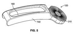
- FIG. 5is a perspective view of one aspect of a sleeve for use with the connecting rod of FIG. 4 ;
- FIG. 6is a side elevational view of the crosslink device of FIG. 1 ;
- FIG. 7is a perspective view of one aspect of a rod gripping assembly for use with a crosslink device
- FIG. 8is a perspective view of the rod gripping assembly of FIG. 7 , showing an elongate aperture
- FIG. 9is a perspective view of one aspect of a rod gripping assembly having a bias member to maintain the jaw members in a normally closed position
- FIG. 10is a perspective view of one aspect of a rod gripping assembly having a bias member to maintain the jaw members in a normally open position;
- FIG. 11is a perspective view of a rod gripping assembly connected to an end of a connecting member, where the connecting member has an elongate aperture.
- Rangescan be expressed herein as from “about” one particular value, and/or to “about” another particular value. When such a range is expressed, another aspect includes from the one particular value and/or to the other particular value. Similarly, when values are expressed as approximations, by use of the antecedent “about,” it will be understood that the particular value forms another aspect. It will be further understood that the endpoints of each of the ranges are significant both in relation to the other endpoint, and independently of the other endpoint.
- the terms “optional” or “optionally”mean that the subsequently described event or circumstance may or may not occur, and that the description includes instances where said event or circumstance occurs and instances where it does not.
- transverse crosslink device 10for connecting substantially parallel rods in a bone screw assembly.
- the devicecomprises a connecting member 100 , a first rod gripping assembly 200 , and a second rod gripping assembly 210 .
- first rod gripping assembly 200is pivotly connected to the first end 110 of the connecting member 100 , such that the first rod gripping assembly can selectively pivot in a direction substantially transverse to the longitudinal axis A L of the connecting member.
- the first rod gripping assemblyis configured to selectively attach to a first stabilizing rod.
- the second rod gripping assembly 210pivotly connected to the second end 120 of the connecting member, such that the second rod gripping assembly can selectively pivot in a direction substantially transverse to the longitudinal axis of the connecting member.
- the second rod gripping assemblyis configured to selectively attach to a second stabilizing rod 410 .
- the rod gripping assembliesare configured to selectively grip a portion of a stabilizer rod.
- the first and second rod gripping assemblieseach comprise a first jaw member 220 and a second jaw member 230 that are designed to selectively grip and release the respective stabilizer bar.
- the first and second jaw memberseach define a jaw cavity 240 therebetween and are configured to move from a first open position in which a respective stabilizer rod can ingress and egress the jaw cavity 240 , and a second closed position in which the respective stabilizer rod is substantially maintained within the jaw cavity.
- first jaw member 220 and second jaw member 230are pivotally connected.
- each jawdefines a pivot aperture 250 in which a pivot pin can reside.
- the first and second jaw membersmove from the first position to the second position in a scissor-like manner, meaning separation of the proximal portions of the first and second jaw members separates the distal portions of the jaw members, and vice-versa.
- the scissor clamping designcreates less stress on the rod than traditional clamps with set screws. This design also allows for top-loading of the implant for easy installation.
- the proximal portion 260 of the first jaw member 220 of the first rod gripping assemblyis pivotally connected to the first end 110 of the connecting member 100 and a proximal portion 270 of the second jaw member 230 of the first rod gripping assembly 200 is connected to the proximal portion 260 of the first jaw member such that it can pivot therewith.
- Thisallows for alignment to rods that are not parallel to one another.
- the proximal portion of each jaw memberdefines an aperture 290 through which a fastener 280 can be positioned.
- the apertures of the first and second jaw membersare substantially coaxial, such that tightening of the fastener 280 draws the proximal end of the second jaw member closer to the proximal end of the first jaw member.
- the first jaw memberis substantially adjacent the first end of the connecting member.
- tightening of one fastenerboth tightens the rod gripping assembly and fixes the rotational position of the rod gripping assembly with respect to the connecting member.
- the second rod gripping assembly 210can be configured in the same fashion, as well.
- the bottom face of the proximal portion of the first jaw member 220 of the first rod gripping assemblycomprises a plurality of radial teeth and a top face of the first end of the connecting member 100 comprises complimentary radial teeth.
- tightening of the fastener 280substantially compresses the proximal portion 260 of the first jaw member with the first end of the connecting member, which engages the radial teeth of the connecting member with the radial teeth of the proximal portion of the first jaw member.
- the engagementsubstantially restricts rotation of the first rod gripping assembly with respect to the connecting member 100 .
- the second rod gripping assembly and the second end 120 of the connecting membercan be configured in the same fashion.
- connection between the second end of the connecting member and the second rod gripping assemblyis telescoping, thereby permitting the second rod gripping assembly to selectively move in a longitudinal direction with respect to the connecting member.
- the first and/or the second end of the connecting member 100can define an elongate aperture 130 through which the fastener connects the respective jaw member to the respective end of the connecting member. When the fastener is loose, it is free to move longitudinally within the elongate aperture 130 . It is also contemplated that one or both of the apertures of the jaw members can also be elongate.
- the first rod gripping assembly 200comprises a first bias member 320 to maintain the first and second jaw members of the first rod gripping device in a normally open position.
- the bias member 320can be positioned therebetween the proximal end of the first jaw member 220 and the second jaw member 230 urging them apart.
- the configurationcan be the same for the second rod gripping assembly 210 , where the bias member would be the second bias member, if desired.
- the first rod gripping assemblycomprises a first bias member 320 to maintain the first and second jaw members of the first rod gripping device in a normally closed position.
- the bias member 320can be positioned therebetween the proximal end of the first jaw member and the first end 110 of the connecting member, urging the proximal ends of the jaw members together. It is also contemplated that the bias member can be positioned therebetween the proximal end of the second jaw member and a head of the fastener 280 .
- the bias memberscan comprise a coil spring, a leaf spring, a wave washer, and the like. Biocompatible materials for the bias member should be used.
- the bias membercan be, for example and not meant to be limiting, Nitinol.
- the connecting member 100comprises a connecting rod 140 and a sleeve 150 .
- the sleeve 150defines a longitudinal sleeve cavity 160 and the rod is configured to at least partially slide within the longitudinal sleeve cavity 160 and be selectively retained therein.
- other manners to vary the length of the connecting memberare contemplated and can be employed.
- the connecting memberis substantially arcuate. This shape allows for clearance of crucial anatomy, such as the spinal cord.
Landscapes
- Health & Medical Sciences (AREA)
- Orthopedic Medicine & Surgery (AREA)
- Life Sciences & Earth Sciences (AREA)
- Neurology (AREA)
- Surgery (AREA)
- Heart & Thoracic Surgery (AREA)
- Engineering & Computer Science (AREA)
- Biomedical Technology (AREA)
- Nuclear Medicine, Radiotherapy & Molecular Imaging (AREA)
- Medical Informatics (AREA)
- Molecular Biology (AREA)
- Animal Behavior & Ethology (AREA)
- General Health & Medical Sciences (AREA)
- Public Health (AREA)
- Veterinary Medicine (AREA)
- Surgical Instruments (AREA)
- Prostheses (AREA)
Abstract
Description
Claims (12)
Priority Applications (2)
| Application Number | Priority Date | Filing Date | Title |
|---|---|---|---|
| US13/336,871US9125691B2 (en) | 2011-12-23 | 2011-12-23 | Transverse crosslink device |
| PCT/US2012/068684WO2013095960A1 (en) | 2011-12-23 | 2012-12-10 | Transverse crosslink device |
Applications Claiming Priority (1)
| Application Number | Priority Date | Filing Date | Title |
|---|---|---|---|
| US13/336,871US9125691B2 (en) | 2011-12-23 | 2011-12-23 | Transverse crosslink device |
Publications (2)
| Publication Number | Publication Date |
|---|---|
| US20130165976A1 US20130165976A1 (en) | 2013-06-27 |
| US9125691B2true US9125691B2 (en) | 2015-09-08 |
Family
ID=48655312
Family Applications (1)
| Application Number | Title | Priority Date | Filing Date |
|---|---|---|---|
| US13/336,871Expired - Fee RelatedUS9125691B2 (en) | 2011-12-23 | 2011-12-23 | Transverse crosslink device |
Country Status (2)
| Country | Link |
|---|---|
| US (1) | US9125691B2 (en) |
| WO (1) | WO2013095960A1 (en) |
Cited By (13)
| Publication number | Priority date | Publication date | Assignee | Title |
|---|---|---|---|---|
| US20150032158A1 (en)* | 2013-07-25 | 2015-01-29 | Amendia Inc. | Percutaneous Pedicle Screw Revision System |
| US20150190178A1 (en)* | 2014-01-09 | 2015-07-09 | Medtronic, Inc. | Spinal correction system and method |
| US10238432B2 (en) | 2017-02-10 | 2019-03-26 | Medos International Sàrl | Tandem rod connectors and related methods |
| US10321939B2 (en) | 2016-05-18 | 2019-06-18 | Medos International Sarl | Implant connectors and related methods |
| US10398476B2 (en) | 2016-12-13 | 2019-09-03 | Medos International Sàrl | Implant adapters and related methods |
| US10492835B2 (en) | 2016-12-19 | 2019-12-03 | Medos International Sàrl | Offset rods, offset rod connectors, and related methods |
| US10517647B2 (en) | 2016-05-18 | 2019-12-31 | Medos International Sarl | Implant connectors and related methods |
| US10561454B2 (en) | 2017-03-28 | 2020-02-18 | Medos International Sarl | Articulating implant connectors and related methods |
| US10966761B2 (en) | 2017-03-28 | 2021-04-06 | Medos International Sarl | Articulating implant connectors and related methods |
| US11076890B2 (en) | 2017-12-01 | 2021-08-03 | Medos International Sàrl | Rod-to-rod connectors having robust rod closure mechanisms and related methods |
| USD951452S1 (en)* | 2020-09-03 | 2022-05-10 | Solco Biomedical Co., Ltd. | Rod connector for cervical vertebrae |
| USD951451S1 (en)* | 2020-09-03 | 2022-05-10 | Solco Biomedical Co., Ltd. | Cross link for cervical vertebrae |
| USD951450S1 (en)* | 2020-09-03 | 2022-05-10 | Solco Biomedical Co., Ltd. | Side screw for cervical vertebrae |
Families Citing this family (6)
| Publication number | Priority date | Publication date | Assignee | Title |
|---|---|---|---|---|
| US20130338714A1 (en) | 2012-06-15 | 2013-12-19 | Arvin Chang | Magnetic implants with improved anatomical compatibility |
| US9072547B2 (en) | 2012-11-06 | 2015-07-07 | Globus Medical, Inc. | Polyaxial cross connector |
| US8911486B1 (en) | 2013-09-16 | 2014-12-16 | Neuraxis, Llc | Implantable devices for thermal therapy and related methods |
| US9308123B2 (en)* | 2013-09-16 | 2016-04-12 | Neuraxis, Llc | Methods and devices for applying localized thermal therapy |
| US11504165B1 (en)* | 2018-10-22 | 2022-11-22 | Advance Research System, Llc | Asymmetric clamp with ultrasonic tissue removal capability |
| DE102019113097B3 (en) | 2019-05-17 | 2020-11-12 | Aesculap Ag | Medical cross connector with floating storage and medical product set with the medical cross connector |
Citations (33)
| Publication number | Priority date | Publication date | Assignee | Title |
|---|---|---|---|---|
| US4433677A (en) | 1981-05-29 | 1984-02-28 | Max Bernhard Ulrich | Implantable splint for correcting lumbosacral spondylodesis |
| US5498262A (en) | 1992-12-31 | 1996-03-12 | Bryan; Donald W. | Spinal fixation apparatus and method |
| US5624442A (en) | 1990-04-26 | 1997-04-29 | Cross Medical Products, Inc. | Transverse link for use with a spinal implant system |
| US5707372A (en) | 1996-07-11 | 1998-01-13 | Third Millennium Engineering, Llc. | Multiple node variable length cross-link device |
| US5709684A (en) | 1995-12-04 | 1998-01-20 | Fastenetix, Llc | Advanced compression locking variable length cross-link device |
| US6238396B1 (en)* | 1999-10-07 | 2001-05-29 | Blackstone Medical, Inc. | Surgical cross-connecting apparatus and related methods |
| US6554831B1 (en) | 2000-09-01 | 2003-04-29 | Hopital Sainte-Justine | Mobile dynamic system for treating spinal disorder |
| US20040010253A1 (en)* | 2000-03-15 | 2004-01-15 | Morrison Matthew M. | Spinal implant connection assembly |
| US20040116928A1 (en) | 2002-10-28 | 2004-06-17 | Young J. Stewart | Multi-axial, cross-link connector system for spinal implants |
| US20050113831A1 (en) | 2002-02-11 | 2005-05-26 | Bruno Franck | Connection system between a spinal rod and a transverse bar |
| US20050228377A1 (en) | 2004-04-07 | 2005-10-13 | Depuy Spine, Inc. | Spinal cross-connectors |
| US20060064092A1 (en) | 2001-05-17 | 2006-03-23 | Howland Robert S | Selective axis serrated rod low profile spinal fixation system |
| US20060161154A1 (en) | 2004-12-10 | 2006-07-20 | Mcafee Paul | Prosthetic spinous process and method |
| US20060189983A1 (en) | 2005-02-22 | 2006-08-24 | Medicinelodge, Inc. | Apparatus and method for dynamic vertebral stabilization |
| US20060195095A1 (en) | 2003-03-24 | 2006-08-31 | Theken Surgical, Llc | Spinal implant adjustment |
| US20060217718A1 (en) | 2005-03-28 | 2006-09-28 | Facet Solutions, Inc. | Facet joint implant crosslinking apparatus and method |
| US20060229616A1 (en) | 2005-03-03 | 2006-10-12 | Accin Corporation | Spinal stabilization using bone anchor seat and cross coupling with improved locking feature |
| US20070055242A1 (en) | 2005-07-27 | 2007-03-08 | Bailly Frank E | Device for securing spinal rods |
| US20070083201A1 (en) | 2005-09-23 | 2007-04-12 | Jones Robert J | Apparatus and methods for spinal implant with variable link mechanism |
| US20070270809A1 (en) | 2006-04-10 | 2007-11-22 | Sdgi Holdings, Inc. | Crosslink interconnection of bone attachment devices |
| US20080243185A1 (en) | 2006-09-27 | 2008-10-02 | Felix Brent A | Spinal stabilizing system |
| US20090018586A1 (en) | 2007-07-13 | 2009-01-15 | Butler Michael S | Spinal Cross-Connector |
| US20090093848A1 (en)* | 2007-10-05 | 2009-04-09 | Douglas Wayne Neary | Enhanced pedicle rod clamp device |
| US20090177234A1 (en) | 2008-01-04 | 2009-07-09 | Butler Michael S | Spinal Cross-Connector With Spinal Extensor Muscle Curvature |
| US20090234390A1 (en) | 2008-03-17 | 2009-09-17 | Partnership Of David A. Poirier And Robert A. Rovner | Implantable spinal fixation crosslink |
| US20090326588A1 (en)* | 2008-06-27 | 2009-12-31 | Innovasis, Inc. | Cross connector |
| US7645294B2 (en) | 2004-03-31 | 2010-01-12 | Depuy Spine, Inc. | Head-to-head connector spinal fixation system |
| US7722645B2 (en) | 2001-09-24 | 2010-05-25 | Bryan Donald W | Pedicle screw spinal fixation device |
| US7744633B2 (en) | 2003-10-22 | 2010-06-29 | Pioneer Surgical Technology, Inc. | Crosslink for securing spinal rods |
| US20100204733A1 (en) | 2007-09-25 | 2010-08-12 | Rathbun David S | Transconnector |
| US20100249842A1 (en) | 2009-03-31 | 2010-09-30 | Dr. Hamid R. Mir | Spinous process cross-link |
| US7837714B2 (en)* | 2006-04-10 | 2010-11-23 | Warsaw Orthopedic, Inc. | Methods and devices for the interconnection of bone attachment devices |
| US20110152934A1 (en)* | 2009-12-23 | 2011-06-23 | Asaad Wagdy W | Transconnector for coupling first and second spinal fixation elements |
- 2011
- 2011-12-23USUS13/336,871patent/US9125691B2/ennot_activeExpired - Fee Related
- 2012
- 2012-12-10WOPCT/US2012/068684patent/WO2013095960A1/enactiveApplication Filing
Patent Citations (33)
| Publication number | Priority date | Publication date | Assignee | Title |
|---|---|---|---|---|
| US4433677A (en) | 1981-05-29 | 1984-02-28 | Max Bernhard Ulrich | Implantable splint for correcting lumbosacral spondylodesis |
| US5624442A (en) | 1990-04-26 | 1997-04-29 | Cross Medical Products, Inc. | Transverse link for use with a spinal implant system |
| US5498262A (en) | 1992-12-31 | 1996-03-12 | Bryan; Donald W. | Spinal fixation apparatus and method |
| US5709684A (en) | 1995-12-04 | 1998-01-20 | Fastenetix, Llc | Advanced compression locking variable length cross-link device |
| US5707372A (en) | 1996-07-11 | 1998-01-13 | Third Millennium Engineering, Llc. | Multiple node variable length cross-link device |
| US6238396B1 (en)* | 1999-10-07 | 2001-05-29 | Blackstone Medical, Inc. | Surgical cross-connecting apparatus and related methods |
| US20040010253A1 (en)* | 2000-03-15 | 2004-01-15 | Morrison Matthew M. | Spinal implant connection assembly |
| US6554831B1 (en) | 2000-09-01 | 2003-04-29 | Hopital Sainte-Justine | Mobile dynamic system for treating spinal disorder |
| US20060064092A1 (en) | 2001-05-17 | 2006-03-23 | Howland Robert S | Selective axis serrated rod low profile spinal fixation system |
| US7722645B2 (en) | 2001-09-24 | 2010-05-25 | Bryan Donald W | Pedicle screw spinal fixation device |
| US20050113831A1 (en) | 2002-02-11 | 2005-05-26 | Bruno Franck | Connection system between a spinal rod and a transverse bar |
| US20040116928A1 (en) | 2002-10-28 | 2004-06-17 | Young J. Stewart | Multi-axial, cross-link connector system for spinal implants |
| US20060195095A1 (en) | 2003-03-24 | 2006-08-31 | Theken Surgical, Llc | Spinal implant adjustment |
| US7744633B2 (en) | 2003-10-22 | 2010-06-29 | Pioneer Surgical Technology, Inc. | Crosslink for securing spinal rods |
| US7645294B2 (en) | 2004-03-31 | 2010-01-12 | Depuy Spine, Inc. | Head-to-head connector spinal fixation system |
| US20050228377A1 (en) | 2004-04-07 | 2005-10-13 | Depuy Spine, Inc. | Spinal cross-connectors |
| US20060161154A1 (en) | 2004-12-10 | 2006-07-20 | Mcafee Paul | Prosthetic spinous process and method |
| US20060189983A1 (en) | 2005-02-22 | 2006-08-24 | Medicinelodge, Inc. | Apparatus and method for dynamic vertebral stabilization |
| US20060229616A1 (en) | 2005-03-03 | 2006-10-12 | Accin Corporation | Spinal stabilization using bone anchor seat and cross coupling with improved locking feature |
| US20060217718A1 (en) | 2005-03-28 | 2006-09-28 | Facet Solutions, Inc. | Facet joint implant crosslinking apparatus and method |
| US20070055242A1 (en) | 2005-07-27 | 2007-03-08 | Bailly Frank E | Device for securing spinal rods |
| US20070083201A1 (en) | 2005-09-23 | 2007-04-12 | Jones Robert J | Apparatus and methods for spinal implant with variable link mechanism |
| US20070270809A1 (en) | 2006-04-10 | 2007-11-22 | Sdgi Holdings, Inc. | Crosslink interconnection of bone attachment devices |
| US7837714B2 (en)* | 2006-04-10 | 2010-11-23 | Warsaw Orthopedic, Inc. | Methods and devices for the interconnection of bone attachment devices |
| US20080243185A1 (en) | 2006-09-27 | 2008-10-02 | Felix Brent A | Spinal stabilizing system |
| US20090018586A1 (en) | 2007-07-13 | 2009-01-15 | Butler Michael S | Spinal Cross-Connector |
| US20100204733A1 (en) | 2007-09-25 | 2010-08-12 | Rathbun David S | Transconnector |
| US20090093848A1 (en)* | 2007-10-05 | 2009-04-09 | Douglas Wayne Neary | Enhanced pedicle rod clamp device |
| US20090177234A1 (en) | 2008-01-04 | 2009-07-09 | Butler Michael S | Spinal Cross-Connector With Spinal Extensor Muscle Curvature |
| US20090234390A1 (en) | 2008-03-17 | 2009-09-17 | Partnership Of David A. Poirier And Robert A. Rovner | Implantable spinal fixation crosslink |
| US20090326588A1 (en)* | 2008-06-27 | 2009-12-31 | Innovasis, Inc. | Cross connector |
| US20100249842A1 (en) | 2009-03-31 | 2010-09-30 | Dr. Hamid R. Mir | Spinous process cross-link |
| US20110152934A1 (en)* | 2009-12-23 | 2011-06-23 | Asaad Wagdy W | Transconnector for coupling first and second spinal fixation elements |
Cited By (26)
| Publication number | Priority date | Publication date | Assignee | Title |
|---|---|---|---|---|
| US20150032158A1 (en)* | 2013-07-25 | 2015-01-29 | Amendia Inc. | Percutaneous Pedicle Screw Revision System |
| US9610104B2 (en)* | 2013-07-25 | 2017-04-04 | Amendia, Inc. | Percutaneous pedicle screw revision system |
| US10039573B2 (en) | 2013-07-25 | 2018-08-07 | Amendia, Inc. | Percutaneous pedicle screw revision system |
| US10888355B2 (en) | 2013-07-25 | 2021-01-12 | Spinal Elements, Inc. | Percutaneous pedicle screw revision system |
| US20150190178A1 (en)* | 2014-01-09 | 2015-07-09 | Medtronic, Inc. | Spinal correction system and method |
| US9486252B2 (en)* | 2014-01-09 | 2016-11-08 | Warsaw Orthopedic, Inc. | Spinal correction system and method |
| US10321939B2 (en) | 2016-05-18 | 2019-06-18 | Medos International Sarl | Implant connectors and related methods |
| US10517647B2 (en) | 2016-05-18 | 2019-12-31 | Medos International Sarl | Implant connectors and related methods |
| US11596451B2 (en) | 2016-05-18 | 2023-03-07 | Medos International Sarl | Implant connectors and related methods |
| US11058463B2 (en) | 2016-05-18 | 2021-07-13 | Medos International Sarl | Implant connectors and related methods |
| US10398476B2 (en) | 2016-12-13 | 2019-09-03 | Medos International Sàrl | Implant adapters and related methods |
| US12150679B2 (en) | 2016-12-19 | 2024-11-26 | Medos International Srl | Offset rods, offset rod connectors, and related methods |
| US10492835B2 (en) | 2016-12-19 | 2019-12-03 | Medos International Sàrl | Offset rods, offset rod connectors, and related methods |
| US11160583B2 (en) | 2016-12-19 | 2021-11-02 | Medos International Sarl | Offset rods, offset rod connectors, and related methods |
| US10869695B2 (en) | 2017-02-10 | 2020-12-22 | Medos International Sarl | Tandem rod connectors and related methods |
| US10238432B2 (en) | 2017-02-10 | 2019-03-26 | Medos International Sàrl | Tandem rod connectors and related methods |
| US11793554B2 (en) | 2017-02-10 | 2023-10-24 | Medos International Sarl | Tandem rod connectors and related methods |
| US10561454B2 (en) | 2017-03-28 | 2020-02-18 | Medos International Sarl | Articulating implant connectors and related methods |
| US12059187B2 (en) | 2017-03-28 | 2024-08-13 | Medos International Sarl | Articulating implant connectors and related methods |
| US10966761B2 (en) | 2017-03-28 | 2021-04-06 | Medos International Sarl | Articulating implant connectors and related methods |
| US11382676B2 (en) | 2017-03-28 | 2022-07-12 | Medos International Sarl | Articulating implant connectors and related methods |
| US11707304B2 (en) | 2017-03-28 | 2023-07-25 | Medos International Sarl | Articulating implant connectors and related methods |
| US11076890B2 (en) | 2017-12-01 | 2021-08-03 | Medos International Sàrl | Rod-to-rod connectors having robust rod closure mechanisms and related methods |
| USD951450S1 (en)* | 2020-09-03 | 2022-05-10 | Solco Biomedical Co., Ltd. | Side screw for cervical vertebrae |
| USD951451S1 (en)* | 2020-09-03 | 2022-05-10 | Solco Biomedical Co., Ltd. | Cross link for cervical vertebrae |
| USD951452S1 (en)* | 2020-09-03 | 2022-05-10 | Solco Biomedical Co., Ltd. | Rod connector for cervical vertebrae |
Also Published As
| Publication number | Publication date |
|---|---|
| US20130165976A1 (en) | 2013-06-27 |
| WO2013095960A1 (en) | 2013-06-27 |
Similar Documents
| Publication | Publication Date | Title |
|---|---|---|
| US9125691B2 (en) | Transverse crosslink device | |
| US9974570B2 (en) | Transverse connector | |
| US8696717B2 (en) | Multi-planar, taper lock screw with additional lock | |
| US9629663B2 (en) | Rod attachment for head to head cross connector | |
| US11350973B2 (en) | Rod reducer | |
| AU2007214918B2 (en) | Dorsal adjusting spinal connector assembly | |
| US8956361B2 (en) | Extended tab bone screw system | |
| EP2645952B1 (en) | Bone screw system | |
| US9717540B2 (en) | Inter-spinous process device and method | |
| JP2014534009A (en) | Reduction device for treatment of spinal cord abnormalities | |
| JPH08505304A (en) | Spinal fixation device | |
| AU2014235383A1 (en) | Cross-braced bilateral spinal rod connector | |
| US10667852B2 (en) | Laminar fixation clamp and method | |
| EP2762095A1 (en) | Device for fixing a bony structure to a support member | |
| JP2019141600A (en) | Percutaneous transverse connector system | |
| US20130090690A1 (en) | Dynamic Rod Assembly | |
| US11246629B2 (en) | Transverse connector | |
| CA2869314C (en) | Spinous process fixation apparatus and method | |
| US10405894B2 (en) | Cervical minimal access fusion system | |
| US11253294B1 (en) | Implantable spine rod crosslink |
Legal Events
| Date | Code | Title | Description |
|---|---|---|---|
| AS | Assignment | Owner name:AMENDIA, INC., GEORGIA Free format text:ASSIGNMENT OF ASSIGNORS INTEREST;ASSIGNOR:GUNN, JOSHUA DAVID, MR.;REEL/FRAME:027715/0155 Effective date:20120131 | |
| AS | Assignment | Owner name:ATLANTIC CAPITAL BANK, GEORGIA Free format text:SECURITY AGREEMENT;ASSIGNOR:AMENDIA, INC.;REEL/FRAME:028141/0759 Effective date:20120430 | |
| AS | Assignment | Owner name:MEDLINE INDUSTRIES, INC., ILLINOIS Free format text:SECURITY AGREEMENT;ASSIGNOR:AMENDIA, INC.;REEL/FRAME:028148/0413 Effective date:20120501 | |
| AS | Assignment | Owner name:JP MORGAN CHASE BANK NA, TEXAS Free format text:SECURITY INTEREST;ASSIGNOR:AMENDIA, INC.;REEL/FRAME:033120/0286 Effective date:20140404 | |
| AS | Assignment | Owner name:SILICON VALLEY BANK, AS ADMINISTRATIVE AGENT, GEOR Free format text:PATENT SECURITY AGREEMENT;ASSIGNORS:AMENDIA, INC.;OMNI ACQUISITION, INC.;REEL/FRAME:033696/0940 Effective date:20140905 | |
| AS | Assignment | Owner name:AMENDIA, INC., GEORGIA Free format text:RELEASE BY SECURED PARTY;ASSIGNOR:JPMORGAN CHASE BANK, N.A.;REEL/FRAME:033771/0759 Effective date:20140908 | |
| ZAAA | Notice of allowance and fees due | Free format text:ORIGINAL CODE: NOA | |
| ZAAB | Notice of allowance mailed | Free format text:ORIGINAL CODE: MN/=. | |
| STCF | Information on status: patent grant | Free format text:PATENTED CASE | |
| AS | Assignment | Owner name:AMENDIA, INC., GEORGIA Free format text:RELEASE BY SECURED PARTY;ASSIGNOR:ATLANTIC CAPITAL BANK;REEL/FRAME:037652/0714 Effective date:20160202 | |
| AS | Assignment | Owner name:AMENDIA, INC., GEORGIA Free format text:RELEASE BY SECURED PARTY;ASSIGNOR:SILICON VALLEY BANK, AS ADMINISTRATIVE AGENT;REEL/FRAME:038578/0828 Effective date:20160429 Owner name:OMNI ACQUISITION INC., GEORGIA Free format text:RELEASE BY SECURED PARTY;ASSIGNOR:SILICON VALLEY BANK, AS ADMINISTRATIVE AGENT;REEL/FRAME:038578/0828 Effective date:20160429 | |
| AS | Assignment | Owner name:ANTARES CAPITAL LP, AS AGENT, ILLINOIS Free format text:SECURITY INTEREST;ASSIGNOR:AMENDIA, INC.;REEL/FRAME:038587/0753 Effective date:20160429 | |
| AS | Assignment | Owner name:CORTLAND CAPITAL MARKET SERVICES LLC, AS AGENT, IL Free format text:SECURITY INTEREST;ASSIGNOR:AMENDIA, INC.;REEL/FRAME:038606/0520 Effective date:20160429 | |
| MAFP | Maintenance fee payment | Free format text:PAYMENT OF MAINTENANCE FEE, 4TH YR, SMALL ENTITY (ORIGINAL EVENT CODE: M2551); ENTITY STATUS OF PATENT OWNER: SMALL ENTITY Year of fee payment:4 | |
| AS | Assignment | Owner name:SPINAL ELEMENTS, INC., CALIFORNIA Free format text:MERGER AND CHANGE OF NAME;ASSIGNORS:SPINAL ELEMENTS, INC.;AMENDIA, INC.;REEL/FRAME:052024/0805 Effective date:20191231 | |
| FEPP | Fee payment procedure | Free format text:MAINTENANCE FEE REMINDER MAILED (ORIGINAL EVENT CODE: REM.); ENTITY STATUS OF PATENT OWNER: SMALL ENTITY | |
| LAPS | Lapse for failure to pay maintenance fees | Free format text:PATENT EXPIRED FOR FAILURE TO PAY MAINTENANCE FEES (ORIGINAL EVENT CODE: EXP.); ENTITY STATUS OF PATENT OWNER: SMALL ENTITY | |
| STCH | Information on status: patent discontinuation | Free format text:PATENT EXPIRED DUE TO NONPAYMENT OF MAINTENANCE FEES UNDER 37 CFR 1.362 | |
| FP | Lapsed due to failure to pay maintenance fee | Effective date:20230908 | |
| AS | Assignment | Owner name:SPINAL ELEMENTS, INC. (F.K.A. AMENDIA, INC.), CALIFORNIA Free format text:RELEASE BY SECURED PARTY;ASSIGNOR:CORTLAND CAPITAL MARKET SERVICES LLC, AS AGENT;REEL/FRAME:067605/0676 Effective date:20240531 Owner name:SPINAL ELEMENTS, INC. (F.K.A. AMENDIA, INC.), CALIFORNIA Free format text:RELEASE BY SECURED PARTY;ASSIGNOR:ANTARES CAPITAL LP, AS ADMINISTRATIVE AGENT;REEL/FRAME:067605/0599 Effective date:20240531 |