US9125552B2 - Optical scanning module and means for attaching the module to medical instruments for introducing the module into the anatomy - Google Patents
Optical scanning module and means for attaching the module to medical instruments for introducing the module into the anatomyDownload PDFInfo
- Publication number
- US9125552B2 US9125552B2US11/830,953US83095307AUS9125552B2US 9125552 B2US9125552 B2US 9125552B2US 83095307 AUS83095307 AUS 83095307AUS 9125552 B2US9125552 B2US 9125552B2
- Authority
- US
- United States
- Prior art keywords
- module
- anatomy
- medical instrument
- radiation
- shaft
- Prior art date
- Legal status (The legal status is an assumption and is not a legal conclusion. Google has not performed a legal analysis and makes no representation as to the accuracy of the status listed.)
- Expired - Fee Related, expires
Links
Images


Classifications
- A—HUMAN NECESSITIES
- A61—MEDICAL OR VETERINARY SCIENCE; HYGIENE
- A61B—DIAGNOSIS; SURGERY; IDENTIFICATION
- A61B1/00—Instruments for performing medical examinations of the interior of cavities or tubes of the body by visual or photographical inspection, e.g. endoscopes; Illuminating arrangements therefor
- A61B1/00064—Constructional details of the endoscope body
- A61B1/00071—Insertion part of the endoscope body
- A61B1/0008—Insertion part of the endoscope body characterised by distal tip features
- A61B1/00096—Optical elements
- A—HUMAN NECESSITIES
- A61—MEDICAL OR VETERINARY SCIENCE; HYGIENE
- A61B—DIAGNOSIS; SURGERY; IDENTIFICATION
- A61B1/00—Instruments for performing medical examinations of the interior of cavities or tubes of the body by visual or photographical inspection, e.g. endoscopes; Illuminating arrangements therefor
- A61B1/00163—Optical arrangements
- A61B1/00172—Optical arrangements with means for scanning
- A—HUMAN NECESSITIES
- A61—MEDICAL OR VETERINARY SCIENCE; HYGIENE
- A61B—DIAGNOSIS; SURGERY; IDENTIFICATION
- A61B1/00—Instruments for performing medical examinations of the interior of cavities or tubes of the body by visual or photographical inspection, e.g. endoscopes; Illuminating arrangements therefor
- A61B1/00163—Optical arrangements
- A61B1/00174—Optical arrangements characterised by the viewing angles
- A61B1/00183—Optical arrangements characterised by the viewing angles for variable viewing angles
- A—HUMAN NECESSITIES
- A61—MEDICAL OR VETERINARY SCIENCE; HYGIENE
- A61B—DIAGNOSIS; SURGERY; IDENTIFICATION
- A61B1/00—Instruments for performing medical examinations of the interior of cavities or tubes of the body by visual or photographical inspection, e.g. endoscopes; Illuminating arrangements therefor
- A61B1/04—Instruments for performing medical examinations of the interior of cavities or tubes of the body by visual or photographical inspection, e.g. endoscopes; Illuminating arrangements therefor combined with photographic or television appliances
- A61B1/041—Capsule endoscopes for imaging
- A—HUMAN NECESSITIES
- A61—MEDICAL OR VETERINARY SCIENCE; HYGIENE
- A61B—DIAGNOSIS; SURGERY; IDENTIFICATION
- A61B5/00—Measuring for diagnostic purposes; Identification of persons
- A61B5/0059—Measuring for diagnostic purposes; Identification of persons using light, e.g. diagnosis by transillumination, diascopy, fluorescence
- A61B5/0062—Arrangements for scanning
- A—HUMAN NECESSITIES
- A61—MEDICAL OR VETERINARY SCIENCE; HYGIENE
- A61B—DIAGNOSIS; SURGERY; IDENTIFICATION
- A61B5/00—Measuring for diagnostic purposes; Identification of persons
- A61B5/0059—Measuring for diagnostic purposes; Identification of persons using light, e.g. diagnosis by transillumination, diascopy, fluorescence
- A61B5/0082—Measuring for diagnostic purposes; Identification of persons using light, e.g. diagnosis by transillumination, diascopy, fluorescence adapted for particular medical purposes
- A61B5/0084—Measuring for diagnostic purposes; Identification of persons using light, e.g. diagnosis by transillumination, diascopy, fluorescence adapted for particular medical purposes for introduction into the body, e.g. by catheters
- A—HUMAN NECESSITIES
- A61—MEDICAL OR VETERINARY SCIENCE; HYGIENE
- A61B—DIAGNOSIS; SURGERY; IDENTIFICATION
- A61B1/00—Instruments for performing medical examinations of the interior of cavities or tubes of the body by visual or photographical inspection, e.g. endoscopes; Illuminating arrangements therefor
- A61B1/04—Instruments for performing medical examinations of the interior of cavities or tubes of the body by visual or photographical inspection, e.g. endoscopes; Illuminating arrangements therefor combined with photographic or television appliances
- A61B1/043—Instruments for performing medical examinations of the interior of cavities or tubes of the body by visual or photographical inspection, e.g. endoscopes; Illuminating arrangements therefor combined with photographic or television appliances for fluorescence imaging
- A—HUMAN NECESSITIES
- A61—MEDICAL OR VETERINARY SCIENCE; HYGIENE
- A61B—DIAGNOSIS; SURGERY; IDENTIFICATION
- A61B17/00—Surgical instruments, devices or methods
- A61B17/068—Surgical staplers, e.g. containing multiple staples or clamps
- A61B17/072—Surgical staplers, e.g. containing multiple staples or clamps for applying a row of staples in a single action, e.g. the staples being applied simultaneously
- A61B17/07207—Surgical staplers, e.g. containing multiple staples or clamps for applying a row of staples in a single action, e.g. the staples being applied simultaneously the staples being applied sequentially
- A—HUMAN NECESSITIES
- A61—MEDICAL OR VETERINARY SCIENCE; HYGIENE
- A61B—DIAGNOSIS; SURGERY; IDENTIFICATION
- A61B17/00—Surgical instruments, devices or methods
- A61B17/28—Surgical forceps
- A61B17/29—Forceps for use in minimally invasive surgery
- A—HUMAN NECESSITIES
- A61—MEDICAL OR VETERINARY SCIENCE; HYGIENE
- A61B—DIAGNOSIS; SURGERY; IDENTIFICATION
- A61B17/00—Surgical instruments, devices or methods
- A61B17/34—Trocars; Puncturing needles
- A—HUMAN NECESSITIES
- A61—MEDICAL OR VETERINARY SCIENCE; HYGIENE
- A61B—DIAGNOSIS; SURGERY; IDENTIFICATION
- A61B17/00—Surgical instruments, devices or methods
- A61B17/42—Gynaecological or obstetrical instruments or methods
- A—HUMAN NECESSITIES
- A61—MEDICAL OR VETERINARY SCIENCE; HYGIENE
- A61B—DIAGNOSIS; SURGERY; IDENTIFICATION
- A61B17/00—Surgical instruments, devices or methods
- A61B17/32—Surgical cutting instruments
- A61B2017/320044—Blunt dissectors
- A—HUMAN NECESSITIES
- A61—MEDICAL OR VETERINARY SCIENCE; HYGIENE
- A61B—DIAGNOSIS; SURGERY; IDENTIFICATION
- A61B5/00—Measuring for diagnostic purposes; Identification of persons
- A61B5/0059—Measuring for diagnostic purposes; Identification of persons using light, e.g. diagnosis by transillumination, diascopy, fluorescence
- A61B5/0071—Measuring for diagnostic purposes; Identification of persons using light, e.g. diagnosis by transillumination, diascopy, fluorescence by measuring fluorescence emission
Definitions
- the present applicationrelates generally to a deployable scanning module and in particular to medical devices for deploying the scanning module within the anatomy.
- U.S. Published Application 2005/0020926discloses a scanned beam imager that may be used in applications in which cameras have been used in the past. In particular it can be used in medical devices such as video endoscopes, laparoscopes, etc.
- the scanned beam imager disclosedhas an illuminator that creates a first beam of light and a scanner that deflects the first beam of light across a field-of-view (FOV).
- the scanned beam of lightsequentially illuminates spots in the FOV corresponding to various beam positions. While the beam illuminates the spots, the illuminating light beam is reflected, absorbed, scattered, refracted, or otherwise affected by the object or material in the FOV to produce scattered light energy. A portion of the scattered light energy travels to detectors that receive the light and produce electrical signals corresponding to the amount of light energy received, which is then converted to separate electrical signals.
- the electrical signalspass to a controller that builds up a digital image and transmits it for further processing, decoding, archiving, printing, display, or other treatment or use.
- Such scanned beam imagersare a useful tool for imaging.
- the scanned beam imagermay be adapted for more than just imaging.
- the “scanned beam imager”may be used to generate a diagnosis beam, treatment beam, or an aiming beam of radiation.
- the “scanned beam imager”may be made on a smaller scale than typical cameras, which will reduce the size of the incision or opening necessary to introduce the “scanned beam imager” into the anatomy.
- the “scanned beam imager”may be deployable itself or be incorporated into a medical instrument to reduce the number of instruments to be introduced into the body.
- a module for attachment to a medical instrument to scan the anatomy with a beam of radiationcomprises a housing suitable for insertion in the anatomy that includes a window and a fastener to attach the housing to a medical instrument, an oscillating reflector within the housing that directs a beam of radiation onto the anatomy, and a collector to receive radiation returned from the anatomy.
- a medical instrument for use with a scanning beam devicecomprises a shaft that is insertable in the anatomy, the shaft including a first working channel, and a deployable module within the first working channel of the shaft for scanning the anatomy.
- the deployable modulecomprises a housing that is suitable for insertion in the anatomy that includes a window, an oscillating reflector within the housing that directs a beam of radiation onto the anatomy, and a collector to receive radiation returned from the anatomy.
- a medical instrumentfor use with a scanning beam device, the medical instrument comprising a shaft that is insertable in the anatomy having a distal penetrating tip, wherein at least a portion of the shaft is transparent, and a module within the shaft to scan the anatomy.
- the modulecomprises an oscillating reflector that directs a beam of radiation on the anatomy, and a collector to receive radiation returned from the anatomy.
- the modulecomprises a resonant reflector that directs a beam of radiation on the anatomy, and a collector to receive radiation returned from the anatomy.
- the surgical staplercomprises a handle portion, a shaft attached to the handle portion, an end effector distally attached to the shaft, and a firing mechanism.
- the handle portionis operably configured to produce a firing mechanism.
- the shafttransfers the firing motion to the end effector.
- the shaftincludes a module for scanning the anatomy, which comprises a resonant reflector that directs a beam of radiation on the anatomy and a collector to receive radiation returned from the anatomy.
- the end effectoris distally attached to the shaft that includes a plurality of surgical staples which are deployable in response to the firing motion.
- the firing mechanismtransfers the firing motion from the handle portion to the end effector.
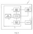
- FIG. 1is a block diagram of an embodiment of a medical device system including a scanner assembly
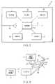
- FIG. 2is a block diagram of an embodiment of a source assembly including multiple sources for generating imaging, therapeutic and aiming beams;
- FIG. 3is a block diagram illustrating radiation paths
- FIG. 4is an illustration of a bi-sinusoidal scan pattern and a rectangular coordinate pattern plotted together;
- FIG. 5is a perspective view of an embodiment of a scanner assembly
- FIG. 6is a side, section view of the scanner assembly of FIG. 5 along line 6 - 6 ;
- FIG. 7is a perspective view of an embodiment of a collector
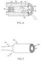
- FIG. 8is a side, section view of a module for scanning the anatomy
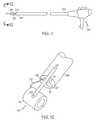
- FIG. 9is a perspective view of an embodiment of a module including fasteners
- FIGS. 10A-10Cillustrate a module being introduced into the anatomy by a medical instrument
- FIG. 11is a side view of a medical instrument with a module attached to the distal end thereof;
- FIG. 12is a perspective view of the distal end of the medical instrument of FIG. 11 along line 12 - 12 ;
- FIG. 13is a side perspective view of a module capable of occupying a first position along the longitudinal axis of the medical instrument and a second position offset therefrom;
- FIG. 14is a side perspective view of a module and medical instrument connected by a first linking member and a second linking member;
- FIG. 15illustrates a partially cut-away side elevation view of a surgical stapling instrument in an open position
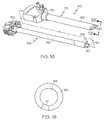
- FIG. 16is a perspective view of a trocar including a module
- FIG. 17is a section view of an embodiment of a trocar including a module within a channel of the trocar;
- FIG. 18is an exploded perspective view of an embodiment of a trocar
- FIG. 19is an end plan view taken along line 19 - 19 of FIG. 18 ;
- FIG. 20is a top view of an embodiment of a surgical instrument
- FIG. 21is a sectional view taken along line 21 - 21 of FIG. 20 ;
- FIGS. 22A and 22Billustrate enlarged perspective views of the jaw members of the surgical instrument in FIG. 20 .
- an embodiment of a scanning beam device 1which may be part of a medical device, includes scanner assembly 2 , collector 3 , radiation source assembly 4 , detector assembly 5 , controller 6 , and user interface 7 .
- the radiation source assembly 4 , detector assembly 5 , controller 6 and user interface 7make up functional element 8 that is known herein as a “console.”
- the radiation source assembly 4as selected by the user via the user interface 7 , and acting through the controller 6 , generates wavelengths of radiation (e.g., in the visible wavelength range or otherwise). This radiation is conveyed in a beam to scanner assembly 2 , which causes the beam to be swept across an anatomical surface.
- the extent of this swept areais generally known as the “field of view” (FOV).
- Radiation returned from the scene (e.g., tissue, structures, and organs) within the FOVmay be received by collector 3 and passed to detector assembly 5 .
- the detector assemblyconverts the received radiation to electrical signals that are then processed by the controller to form an image on a display assembly, which in one embodiment may be included in user interface 7 .
- FIG. 2is a block diagram of one implementation of source assembly 4 .
- Source assembly 4includes multiple sources, each capable of generating radiation at a selected wavelength. Five sources are shown here, numbered 11 thru 15 . It should be noted that while five sources are illustrated, there may be more or fewer sources depending, for example, on the end use.
- the outputs of the radiation sources 11 - 15may be brought together in combiner 16 to yield output beam 17 .
- Combiner 16may also include beam-shaping optics such as one or more collimating lenses and/or apertures.
- the sourcesmay be of various types such as, but not limited thereto, light emitting diodes (LEDs), lasers, thermal sources, arc sources, fluorescent sources, gas discharge sources, or others.
- LEDslight emitting diodes
- laserslasers
- thermal sourcesthermal sources
- arc sourcesfluorescent sources
- gas discharge sourcesor others.
- sources 11 , 12 and 13comprise three lasers; a red diode laser, a green diode-pumped solid state (DPSS) laser, and a blue DPSS laser at approximately 635 nm, 532 nm, and 473 nm, respectively.
- Signals 42may be provided by controller 6 ( FIG. 1 ) to one or more of the sources and optionally combiner 16 .
- Signals 42may optionally control wavelength, power, modulation or other beam properties.
- the power of the beammay be modulated by a modulator, as taught in commonly assigned U.S. patent application Ser. No. 11/716,911, titled POWER MODULATION OF A SCANNING BEAM FOR IMAGING, THERAPY, AND/OR DIAGNOSIS, which is hereby incorporated by reference in its entirety.
- the wavelength of radiationmay be selected for imaging, therapy, or aiming.
- an “imaging beam”refers to radiation selected for use in creating an image of a surface or region
- a “therapeutic beam”refers to radiation selected to provide treatment of a condition such as diseased or damaged tissue
- an “aiming beam”refers to radiation selected to accentuate a portion of the FOV.
- an additional sourcemay provide a “diagnostic beam.”
- a “diagnostic beam” as used hereinrefers to radiation selected for analysis or detection of a disease or other medical condition including, for example, to visualize the presence of (or to activate) a diagnostic marker.
- the diagnostic markercould be naturally occurring (e.g., auto or self fluorescence) or introduced as part of the diagnostic procedure (e.g., fluorescent dyes).
- the apparatus to operate such beamsis disclosed in commonly assigned U.S. patent application Ser. No. 11/716,806, titled MEDICAL DEVICE INCLUDING SCANNED BEAM UNIT FOR IMAGING, THERAPY, AND/OR DIAGNOSIS, as well as the operation of treatment mapping or selecting a treatment path. This reference is hereby incorporated by reference in its entirety.
- FIG. 3illustrates the operation of device 1 .
- Reflector 27which is usually included in scanner assembly 2 , receives a beam of radiation 17 from source assembly 4 and directs the beam onto surface 20 , for example, for one or more of imaging, therapy, diagnostic, or aiming purposes. At one point in time, the beam deflected by reflector 27 is in the direction shown as 21 , and impinges upon the surface to illuminate point 23 . Reflector 27 oscillates in at least one axis (two axes in some embodiments), as indicated by the nearby arrowed arc, so that at some other point in time the deflected beam is in the direction indicated as 22 where, it illuminates point 24 .
- Radiationis, in general, reflected, absorbed, scattered, refracted or otherwise affected by the properties of the surface. Radiation may leave the surface in many directions. Collector 3 , however, may only receive that fraction of radiation which is returned from the surface and falls into the area subtended by its aperture. Regions 25 and 26 show the returned radiation that is captured by collector 3 when the beam is illuminating points 23 and 24 respectively. Directions 21 and 22 are not intended to represent any special part of the scan as the beam may be scanned using reflector 27 beyond them, and scans all points between them as well. Furthermore, a simplified two-dimensional view is represented by FIG. 3 , and in general reflector 27 and collector 3 are adapted to illuminate and receive radiation from surfaces occupying space in three dimensions. Radiation returned from the FOV received by collector 3 is passed to detector assembly 5 .
- MEMS scanner reflectoruses a micro-electromechanical (MEMS) scanner reflector to direct the imaging, aiming and therapeutic beams onto the surface.
- MEMS scanner reflectorsare described in, for example, U.S. Pat. No. 6,140,979, entitled SCANNED DISPLAY WITH PINCH, TIMING, AND DISTORTION CORRECTION; U.S. Pat. No. 6,245,590, entitled FREQUENCY TUNABLE RESONANT SCANNER AND METHOD OF MAKING; U.S. Pat. No. 6,285,489, entitled FREQUENCY TUNABLE RESONANT SCANNER WITH AUXILIARY ARMS; U.S. Pat. No.
- reflector 27scans the beam of radiation in a pattern shown as an idealized bi-resonant or bi-sinusoidal scan pattern.
- High-speed MEMS reflectors and other resonant deflectors as described hereinare configured and driven to execute sinusoidal angular deflections in two orthogonal axes, yielding the Lissajous pattern shown in FIG. 4 .
- Most current display devicesare configured to address display data in a Cartesian form, for example as row and column, or a particular pixel along a nearly-horizontal scan line.
- the bi-resonant or Lissajous scan path 30is shown overlaid with the Cartesian or rectilinear grid 31 .
- the intersections between the vertical and horizontal lines of the Cartesian grid 30represent display pixel positions while the Lissajous trace 31 represents the actual path taken by the scanned spot. As the actual scan path does not align perfectly with all the rectilinear pixel positions, these image values may be determined through interpolation. In some embodiments, registration of the Lissajous trace 30 to the Cartesian grid 31 is based on a marker that links a reference point in the scan to a point in the rectilinear matrix.
- FIG. 5is an external view of one embodiment of the scanner assembly 2 .
- Scanner assembly 2includes a housing 50 that encloses the reflector 27 and other components.
- a source fiber 51is used to deliver radiation from the source assembly 4 to the scanner assembly 2 .
- Source fiber 51may be a single mode optical fiber.
- one or more fibersmay be used to deliver imaging beams and one or more other fibers may be used to deliver a therapeutic beam (e.g., therapeutic beams having longer wavelengths, e.g., greater than 1700 nm and/or higher power).
- a different type of fibersuch as a holey fiber, may be used to transmit energy from the source assembly 4 .
- the same optical fiber 51is used to deliver both the imaging beams and the therapeutic beams to the reflector, the optical fiber defining a common path for both types of beams.
- Electrical wires 52convey drive signals for the reflector 27 and other signals (position feedback, temperature, etc.) to and from controller 6 ( FIG. 1 ). Wires 52 may also provide control and feedback connections for controlling focus characteristics of the beam shaping optic 56 .
- source fiber 51 , electrical wires 52 and any other fibers or wires connected to scanner assembly 2may be bound together into a cable (shown as 76 in FIG. 8 ).
- the distal end of the scanner assembly 2may be fitted with an optical element 53 which allows the scanned beam to illuminate the FOV.
- This element 53is generally referred to and illustrated as a dome; however, its curvature, contour, and surface treatments may depend on the application and optical properties required.
- dome 53provides a hermetic seal with the housing 50 to protect the internal elements from the environment.
- FIG. 6shows one embodiment for the internal components of scanner assembly 2 .
- Source fiber 51is affixed to the housing 50 by ferrule 54 .
- the end of the source fiber 51may be polished to create a beam 55 of known divergence.
- the beam 55may be shaped by a beam shaping optic or lens 56 to create a beam shape appropriate for transmission through the system.
- shaped beam 57is fed through an aperture in the center of reflector 27 , and then reflected off a first reflecting surface 58 .
- First reflecting surface 58may have a beam shaping function. Beam 57 is then directed onto reflector 27 and then out of scanner assembly 2 , the details of which (in the case of an imaging beam) are described in U.S.
- reflector 27Any suitable materials can be used to form reflector 27 .
- the reflective surface of reflector 27may be formed of gold or other suitable material for directing each of the beams including relative high energy therapeutic radiation.
- a multilayer dielectric configurationmay be used in forming reflector 27 .
- Scanner assembly 2may be about 2 to about 4 millimeters by about 4 to about 10 millimeters, or any other suitable dimension. Scanner assembly 2 may by cylindrical, rectangular, or any other configuration that can be inserted into the body, or made part of an introducer. Scanner assembly 2 may be capable of being deployed within the anatomy. In one embodiment, scanner assembly 2 may enter the anatomy through a natural orifice (i.e. the mouth, anus, etc.) for a less invasive procedure.
- a natural orificei.e. the mouth, anus, etc.
- collector 3may include face 60 , central void 61 , covering 62 , and collecting fibers 63 . Radiation reflected from the FOV impinges on the face 60 of collector 3 , which constitutes the receiving aperture. Face 60 may be made up of the polished ends of a large number of small diameter, multimode collecting fibers 63 which conduct the radiation to detector assembly 5 ( FIGS. 1 and 3 ). In one embodiment, scanner assembly 2 is inserted into central void 61 of covering 62 to form a module 70 ( FIG. 8 ) that may include a cable to connect the module 70 to the console 8 of scanning beam device 1 .
- the cablemay include the bundle of collecting fibers, the source fiber, and any other wiring for controlling scanner assembly 2 and collector 3 .
- the fiber ends making up face 60may be formed in a plane, or into other geometries to control the pattern of receiving sensitivity. They may be coated with diffusing or other materials to improve their angle of acceptance, to provide wavelength conversion, or wavelength selectivity.
- detector assembly 5may be configured to form the receiving aperture and mounted in position to receive the reflected radiation directly, without the need for a separate collector 3 .
- Module 70may include an optical fiber 71 , housing 72 , window 73 , ferrule 74 , beam shaping optics 76 , reflector 77 , and collectors 78 .
- Housing 72may be made of any material suitable for insertion in the anatomy.
- housing 72may be metal, plastic, or a combination thereof.
- module 70may be deployable in the anatomy.
- a cablemay extend from the housing 72 .
- Window 73may have optical power and further shape the beam as it passes therethrough.
- collectors 78may be light collecting fibers enclosed by housing 72 .
- Light collecting fibersmay be multi-mode optical fibers that transmit the light to detector assembly 5 in console 8 (see FIG. 1 ) or, in some embodiments, the light collecting fibers may be replaced by optical-to-electrical converters such as photodiodes.
- Collector 78receives radiation that returns from the anatomy that is scanned by the module 70 .
- Module 70may be shown in several figures as a cylindrical unit; however, module 70 is not limited to that configuration.
- Module 70may have an elongated form having a rectangular, square, polygonal, oval, or any other shape to the housing 72 that facilitates movement of the module through a working channel, lumen, or through a portion of the anatomy.
- a lumenmay be a natural or manmade hollow cavity, for example a hollow cavity of a surgical instrument, or a blood vessel or other tubular organ within the anatomy, such as the esophagus, colon, or urethra.
- module 70may be about four millimeters in diameter and about ten millimeters long.
- Module 70may have at least a 140 degree field-of-view.
- Module 70may be introduced through a natural or non-natural opening into the anatomy. Module 70 may be used to visualize other structures or areas within the anatomy such as, but not limited to, regions of the gastrointestinal tract (e.g., stomach, duodenum, small intestine, colon), the respiratory tract (e.g., nose, lower respiratory tract), the urinary tract, the female reproductive system (e.g., cervix, uterus, Fallopian tubes), normally closed body cavities (e.g., abdominal or pelvic cavity, interior of a joint, organs of the chest), during pregnancy (e.g., amnion, fetus), blood vessels, peritoneal space external to organ structures, difficult to visualize areas such as the spine, etc.
- regions of the gastrointestinal tracte.g., stomach, duodenum, small intestine, colon
- the respiratory tracte.g., nose, lower respiratory tract
- the urinary tracte.g., the female reproductive system (e.g., cervix, uterus
- FIG. 9illustrates another embodiment of module 70 including housing 72 , window 73 , and cable 79 .
- the module 70may include a first fastener 82 and a second fastener 84 .
- First fastener 82may be attached to housing 72 to enable housing 72 to be attached to a medical instrument.
- Second fastener 84may be attached to cable 79 to enable cable 79 to be attached to the medical instrument.
- First fastener 82 and second fastener 84may be the same type of fastener.
- the fasteners 82 and 84may be strips or wires that will wrap around the medical instrument, or clips, magnets, adhesive, adhesive coated bands, hook-and-loop or mushroom fabric, etc. to secure the housing 72 against the instrument.
- the fastenersmay be metal, plastic, biomaterial, or any other material suitable for entry into the anatomy.
- the fastenersmay be Mylar strips.
- the first and second fasteners 82 and 84may remain attached to the module 70 so that the module 70 may be attached to various medical instruments.
- the first and second fasteners 82 and 84may be removable from module 70 .
- the first and/or second fasteners 82 and 84 of module 70may be attached to a medical instrument 86 and introduced into the anatomy.
- the medical instrument 86may be a laparoscope, gastroscope, colonoscope, surgical stapler, grasper, catheter, ultrasonic, RF instrument, surgical clip applier, the instrument for inserting GERD fasteners, or any other surgical instrument.
- the module 70is of such a reduced size that the overall size of the instrument is less than those medical instrument including CCD or CMOS focal plane arrays.
- the medical instrument 86may be a cutting tool, or other surgical tools for conducting trans-luminal and trans-gastric surgeries.
- the cutting tool 86may open a port 87 through a portion of the anatomy, and with the module 70 attached thereto, the tool may be moved through the port 87 carrying module 70 .
- the cutting toolis illustrated as being introduced through the esophagus into the stomach where the cutting tool 86 opens a port 87 through the stomach into the peritoneal cavity 88 and then cutting tool 86 carries module 70 into the peritoneal cavity 88 .
- the module 70has a cable 79 extending therefrom to link the module to console 8 .
- cutting tool 86may open the port 87 and a separate transluminal tool with module 70 attached via the first fastener 82 and/or the second fastener 84 may carry module 70 through the port 87 .
- the module 70may be introduced into the anatomy by the cutting tool 86 through a lumen.
- the cutting tool 86 or any other medical instrument carrying module 70may be introduced into the anatomy through a working channel of another medical instrument, such as an endoscope.
- module 70may be moved through the port 87 independently of the cutting tool 86 or any other tool.
- the part of the anatomy to be cutmay need to be held taunt or still during the cutting, and another medical instrument may be needed to hold that part of the anatomy.
- the medical instrument that holds the anatomy tauntmay be included in a specialized transport tool that includes the cutting tool 86 and the module 70 attached together.
- module 70is illustrated as being introduced into the anatomy laparoscopically.
- the module 70may be introduced into the peritoneal cavity 88 by a medical instrument 86 , such as a grasper, biopsy tool, cutting tool, clip applier, etc.
- a trocarmay be used to open a channel into the peritoneal cavity 88 or other part of the anatomy through which the medical instrument 86 carrying the module 70 may be introduced.
- the module 70 and the cable 79 extending therefrommay be fastened to the medical instrument by a first fastener and a second fastener as described above.
- FIG. 10Cillustrates a gynecological entry of module 70 into the anatomy by a medical instrument 86 to which the module is attached.
- the module 70is carried into the uterus 89 by the medical instrument 86 .
- the medical instrumentmay be an endoscope or other medical instrument listed above.
- a cable 79may be extending from module 70 to link the module 70 to console 8 .
- module 70may be attached to a medical instrument 90 by a linkage 92 having a distal end 93 and a proximal end 94 .
- the distal end 93 of the linkage 92may be attached to the housing of module 70 and the proximal end 93 of the linkage 92 may be attached to the medical instrument 90 .
- the medical instrument 90having a distal end 96 and a proximal end 98 .
- the medical instrument 90may be an endoscope, as illustrated in FIG. 11 , or any other medical instrument.
- module 70may extend from the distal end of the medical instrument 90 inline with the medical instrument 90 .
- Module 70may be pivotally attached to the medical instrument 90 .
- the medical instrumentmay be a surgical clip applier that has a module 70 mounted similarly, such that the portions of the anatomy to be clipped together may be scanned by module 70 before being clipped together.
- a surgical clip applierthat has a module 70 mounted similarly, such that the portions of the anatomy to be clipped together may be scanned by module 70 before being clipped together.
- FIG. 12is an end view of one embodiment of medical instrument 90 from FIG. 11 .
- linkage 92may be pivotally attached to housing 72 of module 70 , by a pivot 99 .
- Cable 79may extend from housing 72 .
- Cable 79may enter the distal end 96 of the medical instrument through a port 95 .
- Port 95may be any shape and in any location on the distal end of the medical instrument including the end face 91 or the side of the distal end 96 .
- the medical instrument 90may include a working channel 97 .
- the working channel 97may vary in size and shape as needed to fit the desired instrument(s) to be fed through the channel.
- Module 70may be rotated about the pivotal attachment to the housing 72 to a plurality of positions for scanning the anatomy.
- Module 70may rotate relative to pivot 99 from being inline with the medical instrument 90 .
- a spaceis opened between module 70 and the end face 91 of the medical instrument 90 such that the working channel(s) 97 may be used by other medical tools while module 70 scans the anatomy.
- cable 79may be affixed to an elastic member (not shown in FIG. 12 ) that is attached to the medical instrument within port 95 near the end face 91 .
- the elastic membermay run parallel to or encase a portion of cable 79 proximal to module 70 such that the elastic member is stressed when the module 70 rotates from the inline position. The stress on the elastic element can then retract cable 79 into port 95 when the module 70 returns to the inline position.
- module 70may include a linkage 92 between the module 70 and the medical instrument 90 .
- the linkage 92may be pivotally attached to the module 70 and may be pivotally attached to the medical instrument 90 .
- the linkage 92may move module 70 from being along the longitudinal axis of the medical instrument 90 (i.e., being inline 102 with the medical instrument 90 ) to being offset 104 from the longitudinal axis of the medical instrument 90 .
- the module 70may have a plurality of offset positions.
- module 70may be tilted (i.e., angled or aimed) while offset from of the medical instrument 90 .
- the linkagemay be an arm or a plurality of arms.
- the membermay be a 4-bar linkage.
- the member(s)may be in any arrangement (proportions of the members, placement of the members, placement of the pivots, etc.) to enable a variety of positions and orientations of the module 70 in relation to the distal end of the medical instrument 90 .
- the linkage 92keeps the module 70 in a first position 102 (along the longitudinal axis of the medical instrument 90 ) for ease of entry of the module 70 and medical instrument 90 into the patient's anatomy.
- the module 70may be moved or rotated relative to the distal end of the medical instrument 90 to provide access to the anatomy through the working channels 97 on the medical instrument 90 for other surgical tools.
- the small size of the module 70allows the medical instrument 90 to carry the module 70 to or through narrow lumen or apertures.
- the linkage 92may include a first linking member 112 and a second linking member 114 designed to move the module 70 from the first position 102 (along with the longitudinal axis of the medical instrument 90 ) to any number of offset or second positions 104 in which the module 70 is offset from the longitudinal axis of the medical instrument 90 .
- the first linking member or the second linking member 112 , 114may include an actuator as a portion of the member.
- the actuatormay be a shape memory actuator. The shape memory actuator enables the movement of the module 70 from being in the first position 102 (inline with the medical instrument 90 ) to being offset 104 therefrom.
- the shape memory actuatormay be a shape memory alloy, which applies a lifting force to move the module.
- the shape memory actuatorapplies the lifting force when current (DC current) passes through the shape memory alloy.
- the currentcauses the shape memory alloy to contract, which creates the lifting force.
- the first linking member or the second linking membermay include a spring.
- a “shape memory alloy” or SMAis broadly defined as a metal-based alloy having a reversible solid-state transformation typically known as a martensitic transformation. Such materials typically exhibit the shape-memory effect and superelasticity distinct from conventional metals and alloys. These materials may be ferrous or non-ferrous martensites. Such materials include, but are not limited to, iron-based alloys, copper-based alloys, and nickel-titanium alloys. Ferrous systems include, but are not limited, iron and at least one of manganese, silicon, chromium and nickel, such as iron-manganese-silicon alloys and iron-chromium-nickel alloys.
- Copper-based systemsare typically derived from copper-zinc, copper-aluminum, and copper-tin systems.
- Copper systemsinclude, but are not limited to, copper and at least one of zinc, aluminum and nickel, such as copper-zinc-aluminum alloys, copper-nickel-aluminum alloys, and copper-beryllium-aluminum alloys.
- Nickel based systemsinclude, but are not limited to nickel and at least one of titanium, copper, niobium, palladium, zirconium, and hafnium.
- a commonly used nickel based shape memory alloyis known as Nitinol.
- a holding member 116may engage a detent 118 in the first and/or the second linking members 112 , 114 to hold the module 70 in the offset position after the module has been moved to that position.
- the holding member 116may be any shape, size, or design that will be able to engage the first and/or the second linking members 112 , 114 and hold the module in the offset position.
- the holding member 116may be wedge shaped.
- Holding member 116may protrude from within module 70 or may be attached to the exterior of the module 70 .
- Holding member 116may be bimetallic such that the passage of current through the holding member 116 may move the holding member 116 to engage or disengage the detent 118 .
- the first and/or the second linking member 112 , 114may include a spring 119 to move the module 70 from the offset position back to being inline with the medical instrument 90 .
- the spring 119can move the module 70 when no current is flowing into the shape memory alloy included in the first linking member 112 because the lifting force of that linking member will be removed or when the holding member 116 is disengaged from the detent 118 .
- the springmay be a hairspring. The spring stores energy when the module 70 is moved from being inline with the medical instrument to being offset therefrom that can later be used to move the module 70 back to the inline position.
- a medical instrument 120may include a shaft 124 that is insertable into the anatomy, has a working channel 127 , and includes a module 70 within the working channel 127 .
- the module 70may be mounted within the working channel.
- the module 70may be capable of being released or deployed from the working channel into the anatomy.
- the medical instrument 120may be a surgical stapler 121 .
- the surgical stapler 121may include a handle portion 122 operably configured to produce a firing motion, a shaft 124 attached to handle portion 122 for transferring the firing motion, an end effector 126 distally attached to shaft 124 and responsive to the firing motion, and a firing mechanism responsive to the firing motion that transfers the firing motion to end effector 126 .
- surgical stapler 121includes firing drive member 125 to transfer the firing motion from handle portion 122 to end effector 126 .
- end effector 126may have an E-beam firing bar that advantageously controls the spacing of end effector 126 . Further examples and embodiments of surgical stapler 121 are given in U.S. Pat. Nos. 6,978,921, 6,786,382, and 6,905,057, which are herein incorporated by reference.
- Handle portion 122may include a grip 129 toward which a closure trigger 230 may be pivotally drawn be the user to cause clamping or closing of the end effector 126 .
- Firing trigger 132may also be included in handle portion 122 . Firing trigger 132 may be pivotally drawn toward grip 129 to cause the end effector to respond to the firing motion.
- closure trigger 132is actuated first. Once the user is satisfied with the positioning of the end effector 126 , which may be displayed on a display system using module 70 , the user may draw back closure trigger 130 to its fully closed, locked position proximate to grip 129 . Then, firing trigger 132 is actuated. Firing trigger 132 springedly returns when the user removes pressure.
- Shaft 124includes channel 127 having a distal end toward end effector 126 and a proximal end toward handle portion 122 .
- a port 128enters channel 127 near handle portion 122 .
- Channel 127 and port 128are to receive module 70 therein.
- the housing of module 70may be adapted to securedly fix module 70 into the distal end of channel 127 .
- module 70the user of the scanning beam device 1 may image, diagnose, treat, and/or confirm treatment of the anatomy where the instrument is directed.
- the scanning beam device 1may image and confirm the placement and operation of the medical instrument 120 .
- module 70may be fed through channel 127 to scan the tissue to be stapled, used to diagnose what tissue needs to be stapled, used to confirm that tissue was inserted into the stapler, used to confirm that the stapler functioned properly and that the tissue was stapled completely, or any combination thereof.
- medical instrument 140includes shaft 141 having a distal penetrating tip 142 , module 70 within shaft 141 near penetrating tip 142 to scan an area of a body. Cable 79 may extend from the shaft 141 .
- Medical instrument 140may include a needle or a rigid or flexible trocar.
- distal penetrating tip 142is transparent to enable module 70 to scan an area within the body where penetrating tip 142 has penetrated the body.
- the penetrating tipincludes a window through which module 70 may scan an area within the body. The penetrating tip 142 may be used to penetrate the skin, a body cavity, a lumen, a natural body opening, or an organ.
- medical instrument 140may include a working channel through which other instruments may be introduced into the anatomy. Medical instrument 140 is advantageous because the penetrating tip 142 may be small enough that no post operative closure is needed (i.e., stitches).
- the window 73 of module 70( FIG. 8 ) may be built into the penetrating tip 142 or the shaft 141 of the medical instrument 140 . Possible embodiments of trocars are described in U.S. Pat. No. 5,797,944, which is herein incorporated by reference.
- medical instrument 140may include a channel 144 having a distal opening 145 and a proximal opening 146 .
- module 70may be within channel 144 and may include cable 79 extending from the proximal opening 146 .
- Module 70may be fed through channel 144 to a point near the distal opening 145 while remaining in channel 144 when the penetrating tip is pushed into the anatomy. After penetrating tip 142 is within the anatomy, module 70 may be deployed therein. Medical instrument 140 may be left in place after deploying module 70 or may be removed with module 70 remaining within the anatomy. A rod or plunger may be used to deploy the module 70 through the channel 144 within the medical instrument 140 into the anatomy to deploy the module.
- Module 70may then be secured within the anatomy by applying tension to cable 79 .
- the tensionmay pull module 70 back against the skin, tissue, bone, or muscle near the point of penetration into the anatomy to secure module 70 in place.
- the tensionmay be applied by a counter weight 80 attached to cable 79 .
- a removable or temporary adhesivemay be placed on module 70 to secure the module 70 within the anatomy. If module 70 is deployed within a lumen (i.e., esophagus, colon, urethra, etc.), the module may be secured within the body by the connecting structures disclosed in U.S. patent application Ser. No. 11/749,188 METHODS FOR IMAGING THE ANATOMY WITH AN ANATOMICALLY SECURED SCANNER ASSEMBLY, which is incorporated herein by reference.
- a trocar 150may include cannula 151 , obturator 152 , and a module 70 within the cannula 151 .
- Cannula 151includes sleeve 153 having a distal end and a proximal end, cannula housing 154 , and a passageway 155 therethrough.
- proximalthe portion of the instrument closest to the operator or user
- Passageway 155may receive various members like obturators, endosurgical instrument and the like.
- sleeve 153includes module 70 in the distal end.
- module 70may be shaped to conform to the sleeve 153 .
- Module 70may be mounted within sleeve 153 using any form of attachment.
- the obturator 152may include penetrating tip 156 , retractable blades 157 , shaft 158 , and an obturator handle 159 .
- Obturator 152may be capable of being inserted into and withdrawn from the cannula 151 .
- handle 159mates and locks within cannula housing 154 and penetrating tip 156 of the obturator 152 protrudes from sleeve 153 .
- Other embodiments for trocarsare disclosed in U.S. Pat. Nos.
- the trocar sleevewill probably have a flexible sleeve and the distal tip of the trocar could be all or part of the module that is attached as described in commonly assigned U.S. patent application Ser. Nos. 11/382,173 and 11/382,182, which are herein incorporated by reference.
- the flexible trocar sleeve and the elongate flexible obturatormay include at least two regions of differing rigidity to facilitate positioning the trocar translumenally.
- the trocarmay include a cutting element having at least one blade.
- the cutting elementmay be formed on an outer surface of the distal tip.
- the blademay have a sharp, linear edge.
- the distal tip of the trocarmay also include a paddle extending outward from an outer surface of the distal tip and configured to be rotated to separate tissue.
- FIG. 20illustrates another embodiment configured as a surgical instrument 160 that may be utilized in surgical procedures that includes a module 70 .
- the surgical instrument 160includes an elongated shaft 162 , the shaft 162 having a distal end 163 , a proximal end 164 , and a channel 165 ( FIG. 21 ).
- Surgical instrument 160further includes a first and a second jaw member 166 , 167 that may be movably or pivotally disposed on distal end 163 of elongated shaft 162 such that they pivot about a pivot pin, rivet, screw, or the like 168 which is also fixed to the distal end 163 of elongated shaft 162 .
- Surgical instrument 160further includes handle 169 at the proximal end 164 of elongated shaft 162 .
- Other embodiments for graspersare disclosed in U.S. Pat. Nos. 5,728,121 and 6,024,744, which are incorporated herein by reference.
- Handle 169includes handle members 171 . Handle members 171 being pivotally connected about a pivot pin, rivet, or screw, or the like 172 . At least one of handle members 171 is connected to the jaw members 166 , 167 by wire member 174 , shown in FIG. 21 , disposed through the channel 165 of elongated member 162 . Wire member 174 is connected at one of its ends to at least one of handle members 171 and at its other end to a suitable endoscopic actuating mechanism (not shown) for actuating the jaw members 166 , 167 such that pivoting of the handle member 171 about the pivot pin, rivet, or screw 172 causes the jaw members 166 , 167 to open and close relative to each other. Suitable endoscopic actuating mechanisms are numerous in the surgical arts, any one of which can be employed herein.
- FIG. 21is a view of surgical instrument 160 along line 21 - 21 .
- Elongated shaft 162may be surrounded by an insulating material 176 .
- Channel 165 of elongated shaft 162may have wire member 174 running therethrough, cable 79 of a module 70 running therethrough, and any other leads needed to operate the jaw members 166 , 167 .
- surgical instrument 160includes module 70 mounted within the distal end 163 of elongated shaft 162 .
- Module 70may scan the anatomy within and beyond jaw members 166 , 167 when the members 166 , 167 are in the open position as shown in FIG. 22A .
- Module 70may scan the portion of the anatomy within jaw members 166 , 167 when in a closed position as shown in FIG. 22B .
- Jaw members 166 , 167may be straight or arcuate over at least a portion of the jaw member.
- Jaw members 166 , 167may include grasping or cutting elements 177 , 178 . Grasping or cutting elements 177 , 178 are positioned on jaw members 166 , 167 in an opposed facing relationship.
- the surgical instrument 160may be called a grasper when the jaw members 166 , 167 include grasping elements 177 , 178 .
- the surgical instrument 160may be called scissors when the jaw members 166 , 167 include cutting elements 177 , 178 .
- the surgical instrumentmay be a biopsy device (i.e., biopsy forceps) that has a module 70 mounted similarly, such that the tissue to be biopsied may be scanned by module 70 before being biopsied.
- the module 70may be able to emit a beam of radiation that can act to cut out the tissue or part of the anatomy to be biopsied.
- module 70may be mounted onto elongated shaft 162 near distal end 163 .
- the scanning modulemay be mounted on shaft 162 by being built into the body of the shaft, by being fitted into a covering that is fitted onto elongated shaft 162 , or by fastening a deployable module 70 including a first fastener 82 and optionally a second fastener 84 (as shown in FIG. 9 ) onto elongated shaft 162 .
- a method of cutting tissuecomprising the steps of grasping tissue with surgical instrument 160 including at least two jaw members 166 , 167 and module 70 , compressing the tissue between the jaw members 166 , 167 , and cutting the compressed tissue.
- the cutting stepmay include cutting the tissue with an ultrasonic blade, a beam of radiation from the module, or other cutting tool.
- the methodmay also include the step of scanning the anatomy with a beam of radiation from module 70 .
- the methodmay include the step of collecting radiation returned from the anatomy and generating a displayable image of the anatomy. The displayable image may be used to view: the tissue to be grasped before grasping, the tissue during the grasping step, the tissue compressed between the grasping arms, the tissue during the cutting step, the cut tissue after the cutting step is completed.
Landscapes
- Health & Medical Sciences (AREA)
- Life Sciences & Earth Sciences (AREA)
- Surgery (AREA)
- Molecular Biology (AREA)
- Animal Behavior & Ethology (AREA)
- Biophysics (AREA)
- Pathology (AREA)
- Engineering & Computer Science (AREA)
- Biomedical Technology (AREA)
- Veterinary Medicine (AREA)
- Public Health (AREA)
- Physics & Mathematics (AREA)
- Medical Informatics (AREA)
- Heart & Thoracic Surgery (AREA)
- General Health & Medical Sciences (AREA)
- Nuclear Medicine, Radiotherapy & Molecular Imaging (AREA)
- Radiology & Medical Imaging (AREA)
- Optics & Photonics (AREA)
- Endoscopes (AREA)
Abstract
Description
Claims (9)
Priority Applications (1)
| Application Number | Priority Date | Filing Date | Title |
|---|---|---|---|
| US11/830,953US9125552B2 (en) | 2007-07-31 | 2007-07-31 | Optical scanning module and means for attaching the module to medical instruments for introducing the module into the anatomy |
Applications Claiming Priority (1)
| Application Number | Priority Date | Filing Date | Title |
|---|---|---|---|
| US11/830,953US9125552B2 (en) | 2007-07-31 | 2007-07-31 | Optical scanning module and means for attaching the module to medical instruments for introducing the module into the anatomy |
Publications (2)
| Publication Number | Publication Date |
|---|---|
| US20090036734A1 US20090036734A1 (en) | 2009-02-05 |
| US9125552B2true US9125552B2 (en) | 2015-09-08 |
Family
ID=40338795
Family Applications (1)
| Application Number | Title | Priority Date | Filing Date |
|---|---|---|---|
| US11/830,953Expired - Fee RelatedUS9125552B2 (en) | 2007-07-31 | 2007-07-31 | Optical scanning module and means for attaching the module to medical instruments for introducing the module into the anatomy |
Country Status (1)
| Country | Link |
|---|---|
| US (1) | US9125552B2 (en) |
Cited By (11)
| Publication number | Priority date | Publication date | Assignee | Title |
|---|---|---|---|---|
| US20140135575A1 (en)* | 2008-01-10 | 2014-05-15 | Covidien Lp | Apparatus for endoscopic procedures |
| US20170209050A1 (en)* | 2016-01-26 | 2017-07-27 | Novadaq Technologies Inc. | Configurable platform |
| US20170276602A1 (en)* | 2014-09-01 | 2017-09-28 | Shimadzu Corporation | Light measuring apparatus |
| US10694151B2 (en) | 2006-12-22 | 2020-06-23 | Novadaq Technologies ULC | Imaging system with a single color image sensor for simultaneous fluorescence and color video endoscopy |
| US10779734B2 (en) | 2008-03-18 | 2020-09-22 | Stryker European Operations Limited | Imaging system for combine full-color reflectance and near-infrared imaging |
| US10869645B2 (en) | 2016-06-14 | 2020-12-22 | Stryker European Operations Limited | Methods and systems for adaptive imaging for low light signal enhancement in medical visualization |
| USD916294S1 (en) | 2016-04-28 | 2021-04-13 | Stryker European Operations Limited | Illumination and imaging device |
| US10992848B2 (en) | 2017-02-10 | 2021-04-27 | Novadaq Technologies ULC | Open-field handheld fluorescence imaging systems and methods |
| US20220008068A1 (en)* | 2019-12-13 | 2022-01-13 | Dinesh Vyas | Stapler apparatus and methods for use |
| US11930278B2 (en) | 2015-11-13 | 2024-03-12 | Stryker Corporation | Systems and methods for illumination and imaging of a target |
| US20240358391A1 (en)* | 2019-12-30 | 2024-10-31 | Cilag Gmbh International | Surgical instrument assembly |
Families Citing this family (7)
| Publication number | Priority date | Publication date | Assignee | Title |
|---|---|---|---|---|
| WO2007097034A1 (en)* | 2006-02-27 | 2007-08-30 | Olympus Medical Systems Corp. | Endoscope surgery operation instrument |
| US9125552B2 (en)* | 2007-07-31 | 2015-09-08 | Ethicon Endo-Surgery, Inc. | Optical scanning module and means for attaching the module to medical instruments for introducing the module into the anatomy |
| US20090163943A1 (en)* | 2007-12-20 | 2009-06-25 | Cavanaugh Brian J | Multi-purpose tool for minor surgery |
| US20090208143A1 (en)* | 2008-02-19 | 2009-08-20 | University Of Washington | Efficient automated urothelial imaging using an endoscope with tip bending |
| KR101524723B1 (en)* | 2013-10-31 | 2015-06-02 | 주식회사 옵티메드 | Inspection system capable of laser treatment |
| KR101525457B1 (en) | 2014-02-10 | 2015-06-03 | 한국과학기술연구원 | Endoscope robot having joint structure with high curvature |
| KR101783437B1 (en)* | 2015-10-13 | 2017-09-29 | 한국과학기술연구원 | Endoscope robot |
Citations (388)
| Publication number | Priority date | Publication date | Assignee | Title |
|---|---|---|---|---|
| US3758199A (en) | 1971-11-22 | 1973-09-11 | Sperry Rand Corp | Piezoelectrically actuated light deflector |
| US3959582A (en) | 1975-03-31 | 1976-05-25 | The United States Of America As Represented By The Secretary Of The Navy | Solid state electronically rotatable raster scan for television cameras |
| US4082635A (en) | 1976-08-02 | 1978-04-04 | Ciba-Geigy Corporation | Ultraviolet light-curable diacrylate hydantoin adhesive compositions |
| US4141362A (en) | 1977-05-23 | 1979-02-27 | Richard Wolf Gmbh | Laser endoscope |
| US4313431A (en) | 1978-12-06 | 1982-02-02 | Messerschmitt-Boelkow-Blohm Gesellschaft Mit Beschraenkter Haftung | Endoscopic apparatus with a laser light conductor |
| US4375818A (en)* | 1979-03-12 | 1983-03-08 | Olympus Optical Company Ltd. | Ultrasonic diagnosis system assembled into endoscope |
| US4379039A (en) | 1979-12-29 | 1983-04-05 | Toyo Boseki Kabushiki Kaish | Ultraviolet curable resin composition |
| US4401123A (en)* | 1980-05-09 | 1983-08-30 | Olympus Optical Co., Ltd. | Endoscope having an ultrasonic diagnosis function |
| US4403273A (en) | 1981-01-26 | 1983-09-06 | Olympus Optical Co., Ltd. | Illuminating system for endoscopes |
| US4409477A (en) | 1981-06-22 | 1983-10-11 | Sanders Associates, Inc. | Scanning optical system |
| US4421382A (en) | 1980-04-01 | 1983-12-20 | Asahi Kogaku Kogyo Kabushiki Kaisha | Fiber retaining device for power laser |
| US4524761A (en) | 1981-03-16 | 1985-06-25 | Olympus Optical Co., Ltd. | Endoscope apparatus |
| US4527552A (en) | 1981-03-25 | 1985-07-09 | Olympus Optical Co., Ltd. | Endoscope apparatus |
| US4573465A (en) | 1981-11-19 | 1986-03-04 | Nippon Infrared Industries Co., Ltd. | Laser irradiation apparatus |
| US4576999A (en) | 1982-05-06 | 1986-03-18 | General Electric Company | Ultraviolet radiation-curable silicone release compositions with epoxy and/or acrylic functionality |
| US4597380A (en) | 1982-09-30 | 1986-07-01 | Laser Industries Ltd. | Endoscopic attachment to a surgical laser |
| US4643967A (en) | 1983-07-07 | 1987-02-17 | Bryant Bernard J | Antibody method for lowering risk of susceptibility to HLA-associated diseases in future human generations |
| US4676231A (en) | 1984-09-14 | 1987-06-30 | Olympus Optical Co., Ltd. | Laser probe |
| US4760840A (en) | 1986-12-16 | 1988-08-02 | The Regents Of The University Of California | Endoscopic laser instrument |
| US4763662A (en)* | 1985-06-07 | 1988-08-16 | Olympus Optical Co., Ltd. | Ultrasonic biopsy endoscope with extensible guide sheath |
| US4803550A (en) | 1987-04-17 | 1989-02-07 | Olympus Optical Co., Ltd. | Imaging apparatus having illumination means |
| US4872458A (en) | 1986-09-16 | 1989-10-10 | Olympus Optical Co., Ltd. | Thermotherapy apparatus |
| US4902115A (en) | 1986-09-22 | 1990-02-20 | Olympus Optical Co., Ltd. | Optical system for endoscopes |
| US4902083A (en) | 1988-05-31 | 1990-02-20 | Reflection Technology, Inc. | Low vibration resonant scanning unit for miniature optical display apparatus |
| DE3837248A1 (en) | 1988-10-28 | 1990-05-03 | Teichmann Heinrich Otto Dr Phy | Device for treating skin lesions |
| US4934773A (en) | 1987-07-27 | 1990-06-19 | Reflection Technology, Inc. | Miniature video display system |
| US4938205A (en) | 1988-05-27 | 1990-07-03 | The University Of Connecticut | Endoscope with traced raster and elemental photodetectors |
| US5003300A (en) | 1987-07-27 | 1991-03-26 | Reflection Technology, Inc. | Head mounted display for miniature video display system |
| US5023905A (en) | 1988-07-25 | 1991-06-11 | Reflection Technology, Inc. | Pocket data receiver with full page visual display |
| US5048077A (en) | 1988-07-25 | 1991-09-10 | Reflection Technology, Inc. | Telephone handset with full-page visual display |
| US5074860A (en) | 1989-06-09 | 1991-12-24 | Heraeus Lasersonics, Inc. | Apparatus for directing 10.6 micron laser radiation to a tissue site |
| US5078150A (en) | 1988-05-02 | 1992-01-07 | Olympus Optical Co., Ltd. | Spectral diagnosing apparatus with endoscope |
| US5116317A (en)* | 1988-06-16 | 1992-05-26 | Optimed Technologies, Inc. | Angioplasty catheter with integral fiber optic assembly |
| US5163936A (en) | 1991-01-22 | 1992-11-17 | Reliant Laser Corp. | Endoscopic mirror laser beam delivery system and method for controlling alignment |
| US5163945A (en) | 1991-10-18 | 1992-11-17 | Ethicon, Inc. | Surgical clip applier |
| US5172685A (en) | 1988-05-27 | 1992-12-22 | The University Of Connecticut | Endoscope and video laser camera system therefor |
| US5192288A (en) | 1992-05-26 | 1993-03-09 | Origin Medsystems, Inc. | Surgical clip applier |
| US5200819A (en) | 1988-05-27 | 1993-04-06 | The University Of Connecticut | Multi-dimensional imaging system for endoscope |
| US5200838A (en) | 1988-05-27 | 1993-04-06 | The University Of Connecticut | Lateral effect imaging system |
| US5207670A (en) | 1990-06-15 | 1993-05-04 | Rare Earth Medical, Inc. | Photoreactive suturing of biological materials |
| US5218195A (en) | 1991-06-25 | 1993-06-08 | Fuji Photo Film Co., Ltd. | Scanning microscope, scanning width detecting device, and magnification indicating apparatus |
| US5251025A (en) | 1987-03-05 | 1993-10-05 | Fuji Optical Systems, Inc. | Electronic video dental camera |
| US5251613A (en) | 1991-05-06 | 1993-10-12 | Adair Edwin Lloyd | Method of cervical videoscope with detachable camera |
| US5269289A (en) | 1990-12-25 | 1993-12-14 | Olympus Optical Co., Ltd. | Cavity insert device using fuzzy theory |
| US5318024A (en) | 1985-03-22 | 1994-06-07 | Massachusetts Institute Of Technology | Laser endoscope for spectroscopic imaging |
| US5334991A (en) | 1992-05-15 | 1994-08-02 | Reflection Technology | Dual image head-mounted display |
| US5368015A (en) | 1991-03-18 | 1994-11-29 | Wilk; Peter J. | Automated surgical system and apparatus |
| US5370643A (en) | 1992-07-06 | 1994-12-06 | Ceramoptec, Inc. | Multiple effect laser delivery device and system for medical procedures |
| US5387197A (en) | 1993-02-25 | 1995-02-07 | Ethicon, Inc. | Trocar safety shield locking mechanism |
| US5393647A (en) | 1993-07-16 | 1995-02-28 | Armand P. Neukermans | Method of making superhard tips for micro-probe microscopy and field emission |
| US5427103A (en)* | 1992-06-29 | 1995-06-27 | Olympus Optical Co., Ltd. | MRI apparatus for receiving nuclear-magnetic resonance signals of a living body |
| US5436655A (en) | 1991-08-09 | 1995-07-25 | Olympus Optical Co., Ltd. | Endoscope apparatus for three dimensional measurement for scanning spot light to execute three dimensional measurement |
| US5467104A (en) | 1992-10-22 | 1995-11-14 | Board Of Regents Of The University Of Washington | Virtual retinal display |
| US5470010A (en)* | 1991-04-04 | 1995-11-28 | Ethicon, Inc. | Multiple fire endoscopic stapling mechanism |
| US5488862A (en) | 1993-10-18 | 1996-02-06 | Armand P. Neukermans | Monolithic silicon rate-gyro with integrated sensors |
| US5531740A (en) | 1994-09-06 | 1996-07-02 | Rapistan Demag Corporation | Automatic color-activated scanning treatment of dermatological conditions by laser |
| US5540678A (en)* | 1992-12-31 | 1996-07-30 | Laser Centers Of America | Apparatus and method for efficiently transmitting optic energy from a reuseable optic element to a disposable optic element |
| US5545211A (en) | 1993-09-27 | 1996-08-13 | Sooho Medi-Tech Co., Ltd. | Stent for expanding a lumen |
| US5552452A (en) | 1993-03-15 | 1996-09-03 | Arch Development Corp. | Organic tissue glue for closure of wounds |
| US5557444A (en) | 1994-10-26 | 1996-09-17 | University Of Washington | Miniature optical scanner for a two axis scanning system |
| US5562239A (en)* | 1994-04-28 | 1996-10-08 | Ethicon Endo-Surgery, Inc. | Identification device for surgical instrument |
| US5590660A (en) | 1994-03-28 | 1997-01-07 | Xillix Technologies Corp. | Apparatus and method for imaging diseased tissue using integrated autofluorescence |
| US5596339A (en) | 1992-10-22 | 1997-01-21 | University Of Washington | Virtual retinal display with fiber optic point source |
| US5608451A (en) | 1994-03-11 | 1997-03-04 | Olympus Optical Co., Ltd. | Endoscope apparatus |
| US5629790A (en) | 1993-10-18 | 1997-05-13 | Neukermans; Armand P. | Micromachined torsional scanner |
| US5649952A (en) | 1993-12-28 | 1997-07-22 | Advanced Cardiovascular Systems, Inc. | Expandable stents and method for making same |
| US5657165A (en) | 1995-10-11 | 1997-08-12 | Reflection Technology, Inc. | Apparatus and method for generating full-color images using two light sources |
| US5694237A (en) | 1996-09-25 | 1997-12-02 | University Of Washington | Position detection of mechanical resonant scanner mirror |
| US5701132A (en) | 1996-03-29 | 1997-12-23 | University Of Washington | Virtual retinal display with expanded exit pupil |
| US5713891A (en) | 1995-06-02 | 1998-02-03 | Children's Medical Center Corporation | Modified solder for delivery of bioactive substances and methods of use thereof |
| US5728121A (en) | 1996-04-17 | 1998-03-17 | Teleflex Medical, Inc. | Surgical grasper devices |
| WO1998013720A1 (en) | 1996-09-27 | 1998-04-02 | Medcam, Inc. | Method and apparatus for optical scanning |
| US5735792A (en) | 1992-11-25 | 1998-04-07 | Clarus Medical Systems, Inc. | Surgical instrument including viewing optics and an atraumatic probe |
| US5742421A (en) | 1996-03-01 | 1998-04-21 | Reflection Technology, Inc. | Split lens video display system |
| US5742419A (en) | 1995-11-07 | 1998-04-21 | The Board Of Trustees Of The Leland Stanford Junior Universtiy | Miniature scanning confocal microscope |
| US5768461A (en) | 1995-11-02 | 1998-06-16 | General Scanning, Inc. | Scanned remote imaging method and system and method of determining optimum design characteristics of a filter for use therein |
| US5797944A (en)* | 1992-11-12 | 1998-08-25 | Ethicon Endo-Surgery, Inc. | Visualization trocar |
| US5817061A (en)* | 1997-05-16 | 1998-10-06 | Ethicon Endo-Surgery, Inc. | Trocar assembly |
| US5823943A (en) | 1994-08-02 | 1998-10-20 | Olympus Optical Co., Ltd | Light source device for endoscopes |
| US5827176A (en) | 1996-02-13 | 1998-10-27 | Fuji Photo Optical Co., Ltd. | Endoscopic imaging system with rotating photoelectric line sensor |
| US5833689A (en)* | 1994-10-26 | 1998-11-10 | Snj Company, Inc. | Versatile electrosurgical instrument capable of multiple surgical functions |
| US5841553A (en) | 1995-12-26 | 1998-11-24 | Xros, Inc. | Compact document scanner or printer engine |
| US5861549A (en) | 1996-12-10 | 1999-01-19 | Xros, Inc. | Integrated Silicon profilometer and AFM head |
| US5867297A (en) | 1997-02-07 | 1999-02-02 | The Regents Of The University Of California | Apparatus and method for optical scanning with an oscillatory microelectromechanical system |
| WO1999018456A1 (en) | 1997-10-08 | 1999-04-15 | Universite Joseph Fourier | Lens with variable focus |
| US5895866A (en) | 1996-01-22 | 1999-04-20 | Neukermans; Armand P. | Micromachined silicon micro-flow meter |
| US5903397A (en) | 1998-05-04 | 1999-05-11 | University Of Washington | Display with multi-surface eyepiece |
| US5907425A (en) | 1995-12-19 | 1999-05-25 | The Board Of Trustees Of The Leland Stanford Junior University | Miniature scanning confocal microscope |
| US5913591A (en) | 1998-01-20 | 1999-06-22 | University Of Washington | Augmented imaging using a silhouette to improve contrast |
| US5947930A (en) | 1997-03-26 | 1999-09-07 | Ethicon Endo-Surgery, Inc. | Trocar having protector with sinusoidal member |
| US5969465A (en) | 1997-04-01 | 1999-10-19 | Xros, Inc. | Adjusting operating characteristics of micromachined torsional oscillators |
| US5982555A (en) | 1998-01-20 | 1999-11-09 | University Of Washington | Virtual retinal display with eye tracking |
| US5982528A (en) | 1998-01-20 | 1999-11-09 | University Of Washington | Optical scanner having piezoelectric drive |
| WO1999058930A1 (en) | 1998-05-14 | 1999-11-18 | Metacreations Corporation | Structured-light, triangulation-based three-dimensional digitizer |
| US5995264A (en) | 1998-01-20 | 1999-11-30 | University Of Washington | Counter balanced optical scanner |
| US6008781A (en) | 1992-10-22 | 1999-12-28 | Board Of Regents Of The University Of Washington | Virtual retinal display |
| US6013025A (en) | 1996-07-11 | 2000-01-11 | Micro Medical Devices, Inc. | Integrated illumination and imaging system |
| US6016440A (en) | 1996-07-29 | 2000-01-18 | Bruker Analytik Gmbh | Device for infrared (IR) spectroscopic investigations of internal surfaces of a body |
| US6017603A (en) | 1995-04-28 | 2000-01-25 | Nippon Kayaku Kabushiki Kaisha | Ultraviolet-curing adhesive composition and article |
| US6017356A (en) | 1997-09-19 | 2000-01-25 | Ethicon Endo-Surgery Inc. | Method for using a trocar for penetration and skin incision |
| US6024744A (en) | 1997-08-27 | 2000-02-15 | Ethicon, Inc. | Combined bipolar scissor and grasper |
| US6043799A (en) | 1998-02-20 | 2000-03-28 | University Of Washington | Virtual retinal display with scanner array for generating multiple exit pupils |
| US6044705A (en) | 1993-10-18 | 2000-04-04 | Xros, Inc. | Micromachined members coupled for relative rotation by torsion bars |
| US6046720A (en) | 1997-05-07 | 2000-04-04 | University Of Washington | Point source scanning apparatus and method |
| US6049407A (en) | 1997-05-05 | 2000-04-11 | University Of Washington | Piezoelectric scanner |
| US6056721A (en) | 1997-08-08 | 2000-05-02 | Sunscope International, Inc. | Balloon catheter and method |
| US6057952A (en) | 1999-01-14 | 2000-05-02 | Olympus Optical Co., Ltd. | Light scanning device and confocal optical device using the same |
| US6059720A (en) | 1997-03-07 | 2000-05-09 | Asahi Kogaku Kogyo Kabushiki Kaisha | Endoscope system with amplification of fluorescent image |
| US6064779A (en) | 1997-07-23 | 2000-05-16 | Xros, Inc. | Handheld document scanner |
| US6086528A (en) | 1997-09-11 | 2000-07-11 | Adair; Edwin L. | Surgical devices with removable imaging capability and methods of employing same |
| US6097353A (en) | 1998-01-20 | 2000-08-01 | University Of Washington | Augmented retinal display with view tracking and data positioning |
| WO2000013210A9 (en) | 1998-09-02 | 2000-08-31 | Xros Inc | Micromachined members coupled for relative rotation by torsional flexure hinges |
| US6122394A (en) | 1996-05-01 | 2000-09-19 | Xros, Inc. | Compact, simple, 2D raster, image-building fingerprint scanner |
| US6139175A (en) | 1996-05-15 | 2000-10-31 | Olympus Optical Co., Ltd. | Light source for endoscopes, having different numerical-aperture light collection system |
| US6140979A (en) | 1998-08-05 | 2000-10-31 | Microvision, Inc. | Scanned display with pinch, timing, and distortion correction |
| US6151167A (en) | 1998-08-05 | 2000-11-21 | Microvision, Inc. | Scanned display with dual signal fiber transmission |
| US6154321A (en) | 1998-01-20 | 2000-11-28 | University Of Washington | Virtual retinal display with eye tracking |
| US6172789B1 (en) | 1999-01-14 | 2001-01-09 | The Board Of Trustees Of The Leland Stanford Junior University | Light scanning device and confocal optical device using the same |
| US6178346B1 (en) | 1998-10-23 | 2001-01-23 | David C. Amundson | Infrared endoscopic imaging in a liquid with suspended particles: method and apparatus |
| US6179776B1 (en) | 1999-03-12 | 2001-01-30 | Scimed Life Systems, Inc. | Controllable endoscopic sheath apparatus and related method of use |
| US6191761B1 (en) | 1998-11-09 | 2001-02-20 | University Of Washington | Method and apparatus for determining optical distance |
| US6192267B1 (en) | 1994-03-21 | 2001-02-20 | Scherninski Francois | Endoscopic or fiberscopic imaging device using infrared fluorescence |
| US6200595B1 (en) | 1998-04-24 | 2001-03-13 | Kuraray Co., Ltd. | Medical adhesive |
| US6204832B1 (en) | 1997-05-07 | 2001-03-20 | University Of Washington | Image display with lens array scanning relative to light source array |
| US6207392B1 (en) | 1997-11-25 | 2001-03-27 | The Regents Of The University Of California | Semiconductor nanocrystal probes for biological applications and process for making and using such probes |
| US6210401B1 (en) | 1991-08-02 | 2001-04-03 | Shui T. Lai | Method of, and apparatus for, surgery of the cornea |
| US6221068B1 (en) | 1998-01-15 | 2001-04-24 | Northwestern University | Method for welding tissue |
| US6229139B1 (en) | 1998-07-23 | 2001-05-08 | Xros, Inc. | Handheld document scanner |
| US6235017B1 (en) | 1997-03-11 | 2001-05-22 | Vitcon Projektconsult Gmbh | Device for ablation of material by means of laser radiation |
| US6245590B1 (en) | 1999-08-05 | 2001-06-12 | Microvision Inc. | Frequency tunable resonant scanner and method of making |
| US6256131B1 (en) | 1999-08-05 | 2001-07-03 | Microvision Inc. | Active tuning of a torsional resonant structure |
| US6276798B1 (en) | 1998-09-29 | 2001-08-21 | Applied Spectral Imaging, Ltd. | Spectral bio-imaging of the eye |
| US6281862B1 (en) | 1998-11-09 | 2001-08-28 | University Of Washington | Scanned beam display with adjustable accommodation |
| US6285489B1 (en) | 1999-08-05 | 2001-09-04 | Microvision Inc. | Frequency tunable resonant scanner with auxiliary arms |
| US6284185B1 (en) | 1995-04-28 | 2001-09-04 | Nippon Kayaku Kabushiki Kaisha | Ultraviolet-curable adhesive composition for bonding opaque substrates |
| US6292287B1 (en) | 1999-05-20 | 2001-09-18 | Olympus Optical Co., Ltd. | Scanning confocal optical device |
| US6294239B1 (en) | 1995-04-28 | 2001-09-25 | Nippon Kayaku Kabushiki Kaisha | Ultraviolet-curable adhesive composition |
| US6294775B1 (en) | 1999-06-08 | 2001-09-25 | University Of Washington | Miniature image acquistion system using a scanning resonant waveguide |
| US6293911B1 (en) | 1996-11-20 | 2001-09-25 | Olympus Optical Co., Ltd. | Fluorescent endoscope system enabling simultaneous normal light observation and fluorescence observation in infrared spectrum |
| US6296608B1 (en)* | 1996-07-08 | 2001-10-02 | Boston Scientific Corporation | Diagnosing and performing interventional procedures on tissue in vivo |
| EP1139141A2 (en) | 2000-03-27 | 2001-10-04 | Cronos Integrated Microsystems, Inc. | Microelectromechanical devices having brake assemblies therein to control movement of optical shutters and other movable elements |
| US6323037B1 (en) | 1998-04-06 | 2001-11-27 | Cornell Research Foundation, Inc. | Composition for tissue welding and method of use |
| US6327493B1 (en) | 1997-08-28 | 2001-12-04 | Olympus Optical Co., Ltd. | Light scanning devices of a water-tight structure to be inserted into a body cavity to obtain optical information on inside of a biological tissue |
| US6331909B1 (en) | 1999-08-05 | 2001-12-18 | Microvision, Inc. | Frequency tunable resonant scanner |
| US6333110B1 (en) | 1998-11-10 | 2001-12-25 | Bio-Pixels Ltd. | Functionalized nanocrystals as visual tissue-specific imaging agents, and methods for fluorescence imaging |
| US20010055462A1 (en)* | 2000-06-19 | 2001-12-27 | Seibel Eric J. | Medical imaging, diagnosis, and therapy using a scanning single optical fiber system |
| US6338641B2 (en) | 1998-07-24 | 2002-01-15 | Krone Gmbh | Electrical connector |
| US20020015724A1 (en) | 1998-08-10 | 2002-02-07 | Chunlin Yang | Collagen type i and type iii hemostatic compositions for use as a vascular sealant and wound dressing |
| US20020021356A1 (en)* | 2000-08-21 | 2002-02-21 | Asahi Kogaku Kogyo Kabushiki Kaisha | Imaging element for electronic endoscopes and electronic endoscope equipped with the imaging element |
| US20020024495A1 (en) | 1998-08-05 | 2002-02-28 | Microvision, Inc. | Scanned beam display |
| US6353183B1 (en) | 1996-05-23 | 2002-03-05 | The Siemon Company | Adapter plate for use with cable adapters |
| WO2001060274A3 (en) | 2000-02-16 | 2002-03-14 | Diego Syrowicz | Method and apparatus for treating an undesired presence on the skin of an individual |
| US6362912B1 (en) | 1999-08-05 | 2002-03-26 | Microvision, Inc. | Scanned imaging apparatus with switched feeds |
| US6364829B1 (en) | 1999-01-26 | 2002-04-02 | Newton Laboratories, Inc. | Autofluorescence imaging system for endoscopy |
| US6370422B1 (en) | 1998-03-19 | 2002-04-09 | Board Of Regents, The University Of Texas System | Fiber-optic confocal imaging apparatus and methods of use |
| US6370406B1 (en) | 1995-11-20 | 2002-04-09 | Cirrex Corp. | Method and apparatus for analyzing a test material by inducing and detecting light-matter interactions |
| US6369928B1 (en) | 2000-11-01 | 2002-04-09 | Optical Biopsy Technologies, Inc. | Fiber-coupled, angled-dual-illumination-axis confocal scanning microscopes for performing reflective and two-photon fluorescence imaging |
| US6373995B1 (en) | 1998-11-05 | 2002-04-16 | Agilent Technologies, Inc. | Method and apparatus for processing image data acquired by an optical scanning device |
| US20020050956A1 (en) | 2000-09-11 | 2002-05-02 | Microvision, Inc. | Scanned display with pinch, timing, and distortion correction |
| US6384406B1 (en) | 1999-08-05 | 2002-05-07 | Microvision, Inc. | Active tuning of a torsional resonant structure |
| US6396461B1 (en) | 1998-08-05 | 2002-05-28 | Microvision, Inc. | Personal display with vision tracking |
| US20020075284A1 (en) | 2000-08-03 | 2002-06-20 | Rabb Maurice F. | Display of images and image transitions |
| WO2001010322A9 (en) | 1999-08-09 | 2002-06-27 | Visx Inc | Motion detector for eye ablative laser delivery systems |
| US6414779B1 (en) | 2000-11-30 | 2002-07-02 | Opeical Biopsy Technologies, Inc. | Integrated angled-dual-axis confocal scanning endoscopes |
| US6417502B1 (en) | 1998-08-05 | 2002-07-09 | Microvision, Inc. | Millimeter wave scanning imaging system having central reflectors |
| US20020088925A1 (en) | 1998-08-05 | 2002-07-11 | Microvision, Inc. | Low light viewer with image simulation |
| US6423956B1 (en) | 2000-07-28 | 2002-07-23 | Optical Biopsy Technologies | Fiber-coupled, high-speed, integrated, angled-dual-axis confocal scanning microscopes employing vertical cross-section scanning |
| US6426013B1 (en) | 1993-10-18 | 2002-07-30 | Xros, Inc. | Method for fabricating micromachined members coupled for relative rotation |
| US6425900B1 (en) | 2000-10-19 | 2002-07-30 | Ethicon Endo-Surgery | Method for attaching hernia mesh |
| US6433907B1 (en) | 1999-08-05 | 2002-08-13 | Microvision, Inc. | Scanned display with plurality of scanning assemblies |
| US6435637B1 (en) | 1999-10-29 | 2002-08-20 | Scitex Digital Printing, Inc. | Fluid and vacuum control in an ink jet printing system |
| US20020115922A1 (en) | 2001-02-12 | 2002-08-22 | Milton Waner | Infrared assisted monitoring of a catheter |
| US6441356B1 (en) | 2000-07-28 | 2002-08-27 | Optical Biopsy Technologies | Fiber-coupled, high-speed, angled-dual-axis optical coherence scanning microscopes |
| US6445362B1 (en) | 1999-08-05 | 2002-09-03 | Microvision, Inc. | Scanned display with variation compensation |
| US6447524B1 (en)* | 2000-10-19 | 2002-09-10 | Ethicon Endo-Surgery, Inc. | Fastener for hernia mesh fixation |
| US6454762B1 (en)* | 1998-01-27 | 2002-09-24 | Karl Storz Gmbh & Co. Kg | Instrument for applying light, especially laser light, to the human or animal body |
| US20020141026A1 (en) | 2001-02-06 | 2002-10-03 | Wiklof Christopher A. | Scanner and method for sweeping a beam across a target |
| US6462770B1 (en) | 1998-04-20 | 2002-10-08 | Xillix Technologies Corp. | Imaging system with automatic gain control for reflectance and fluorescence endoscopy |
| WO2002062239A3 (en) | 2001-02-02 | 2002-10-10 | Omnisonics Medical Tech | Method of removing occlusions using ultrasonic medical device operating in a transverse mode |
| US6464363B1 (en) | 1999-03-17 | 2002-10-15 | Olympus Optical Co., Ltd. | Variable mirror, optical apparatus and decentered optical system which include variable mirror, variable-optical characteristic optical element or combination thereof |
| US6467345B1 (en) | 1993-10-18 | 2002-10-22 | Xros, Inc. | Method of operating micromachined members coupled for relative rotation |
| US6470124B1 (en) | 1998-09-15 | 2002-10-22 | Assistance Publique - Hopitaux De Paris | Device for observation inside a body providing improved quality of observation |
| US20020158814A1 (en) | 2001-04-09 | 2002-10-31 | Bright Gregory Scott | Electronically scanned beam display |
| US6477403B1 (en) | 1999-08-09 | 2002-11-05 | Asahi Kogaku Kogyo Kabushiki Kaisha | Endoscope system |
| US6478809B1 (en) | 2000-02-04 | 2002-11-12 | Gregory R. Brotz | Suture and method of use |
| US20020171776A1 (en) | 2001-05-15 | 2002-11-21 | Microvision, Inc. | System and method for capturing, transmitting, and displaying an image |
| US20020171937A1 (en) | 2001-05-15 | 2002-11-21 | Microvision, Inc. | System and method for producing an image with a screen using erase (off) and image (on) light sources |
| US20020173786A1 (en)* | 2001-05-21 | 2002-11-21 | Kortenbach Juergen A. | Methods and apparatus for on-endoscope instruments having end effectors and combinations of on-endoscope and through-endoscope instruments |
| US6485413B1 (en) | 1991-04-29 | 2002-11-26 | The General Hospital Corporation | Methods and apparatus for forward-directed optical scanning instruments |
| US6494578B1 (en) | 2000-07-13 | 2002-12-17 | The Regents Of The University Of California | Virtual reality peripheral vision scotoma screening |
| US6503196B1 (en) | 1997-01-10 | 2003-01-07 | Karl Storz Gmbh & Co. Kg | Endoscope having a composite distal closure element |
| US20030013960A1 (en)* | 2001-05-29 | 2003-01-16 | Makin Inder Raj. S. | Guiding ultrasound end effector for medical treatment |
| US6510338B1 (en) | 1998-02-07 | 2003-01-21 | Karl Storz Gmbh & Co. Kg | Method of and devices for fluorescence diagnosis of tissue, particularly by endoscopy |
| US6515781B2 (en) | 1999-08-05 | 2003-02-04 | Microvision, Inc. | Scanned imaging apparatus with switched feeds |
| US6513939B1 (en) | 2002-03-18 | 2003-02-04 | Nortel Networks Limited | Micro-mirrors with variable focal length, and optical components comprising micro-mirrors |
| US20030030753A1 (en) | 2000-02-10 | 2003-02-13 | Tetsujiro Kondo | Image processing device and method, and recording medium |
| US20030032143A1 (en) | 2000-07-24 | 2003-02-13 | Neff Thomas B. | Collagen type I and type III compositions for use as an adhesive and sealant |
| US6520972B2 (en) | 2000-02-04 | 2003-02-18 | Stephen F. Peters | Surgical clip applier |
| US20030034709A1 (en) | 2001-07-31 | 2003-02-20 | Iolon, Inc. | Micromechanical device having braking mechanism |
| US6525310B2 (en) | 1999-08-05 | 2003-02-25 | Microvision, Inc. | Frequency tunable resonant scanner |
| US6527708B1 (en) | 1999-07-02 | 2003-03-04 | Pentax Corporation | Endoscope system |
| US6529770B1 (en) | 2000-11-17 | 2003-03-04 | Valentin Grimblatov | Method and apparatus for imaging cardiovascular surfaces through blood |
| US6530698B1 (en) | 1999-07-09 | 2003-03-11 | Sumitomo Electric Industries, Ltd. | Optical device |
| US6537211B1 (en) | 1998-01-26 | 2003-03-25 | Massachusetts Institute Of Technology | Flourescence imaging endoscope |
| US20030058190A1 (en) | 2001-09-21 | 2003-03-27 | Microvision, Inc. | Scanned display with pinch, timing, and distortion correction |
| US6545260B1 (en) | 1999-11-19 | 2003-04-08 | Olympus Optical Co., Ltd. | Light scanning optical device which acquires a high resolution two-dimensional image without employing a charge-coupled device |
| US20030086172A1 (en) | 2001-11-02 | 2003-05-08 | Microvision, Inc. | Apparatus and methods for generating multiple exit-pupil images in an expanded exit pupil |
| US6563105B2 (en) | 1999-06-08 | 2003-05-13 | University Of Washington | Image acquisition with depth enhancement |
| US6563106B1 (en) | 2000-02-01 | 2003-05-13 | Calient Networks, Inc. | Micro-electro-mechanical-system (MEMS) mirror device and methods for fabricating the same |
| US20030092995A1 (en) | 2001-11-13 | 2003-05-15 | Medtronic, Inc. | System and method of positioning implantable medical devices |
| US6572606B2 (en) | 2000-01-12 | 2003-06-03 | Lasersight Technologies, Inc. | Laser fluence compensation of a curved surface |
| US6583772B1 (en) | 1998-08-05 | 2003-06-24 | Microvision, Inc. | Linked scanner imaging system and method |
| US6583117B2 (en) | 1995-01-20 | 2003-06-24 | The Microsearch Foundation Of Australia | Method of tissue repair |
| US6585642B2 (en) | 2000-07-18 | 2003-07-01 | Evergreen Medical Incorporated | Endoscope with a removable suction tube |
| US20030130562A1 (en) | 2002-01-09 | 2003-07-10 | Scimed Life Systems, Inc. | Imaging device and related methods |
| US20030142934A1 (en) | 2001-12-10 | 2003-07-31 | Carnegie Mellon University And University Of Pittsburgh | Endoscopic imaging system |
| US6603552B1 (en) | 1999-12-22 | 2003-08-05 | Xillix Technologies Corp. | Portable system for detecting skin abnormalities based on characteristic autofluorescence |
| US6608297B2 (en) | 1997-07-23 | 2003-08-19 | Xeros, Inc. | Scanner document speed encoder |
| WO2003069380A1 (en) | 2002-02-14 | 2003-08-21 | Koninklijke Philips Electronics N.V. | Variable focus lens |
| US20030159447A1 (en) | 2000-05-29 | 2003-08-28 | Massimo Sergio | Refrigerated beverage dispenser provided with a sanitizing device |
| US20030191459A1 (en)* | 1999-06-23 | 2003-10-09 | Ganz Robert A. | Apparatus and method for debilitating or killing microorganisms within the body |
| US6639719B2 (en) | 2001-05-15 | 2003-10-28 | Microvision, Inc. | System and method for using multiple beams to respectively scan multiple regions of an image |
| US6650877B1 (en) | 1999-04-30 | 2003-11-18 | Microvision, Inc. | Method and system for identifying data locations associated with real world observations |
| US20030216729A1 (en) | 2002-05-20 | 2003-11-20 | Marchitto Kevin S. | Device and method for wound healing and uses therefor |
| US20030214460A1 (en) | 2002-05-17 | 2003-11-20 | Microvision, Inc. | Scanning-mirror structure having a cut or a composite design to reduce deformation of the mirror face, and related system and method |
| US6653621B2 (en) | 2001-03-23 | 2003-11-25 | Microvision, Inc. | Frequency tunable resonant scanner and method of making |
| US6654158B2 (en) | 2001-04-20 | 2003-11-25 | Microvision, Inc. | Frequency tunable resonant scanner with auxiliary arms |
| WO2003098918A1 (en) | 2002-05-17 | 2003-11-27 | Microvision, Inc. | Apparatus and method for sweeping an image beam in one dimension and bidirectionally sweeping an image beam in a second dimension |
| US6661393B2 (en) | 1999-08-05 | 2003-12-09 | Microvision, Inc. | Scanned display with variation compensation |
| US6685804B1 (en) | 1999-10-22 | 2004-02-03 | Sanyo Electric Co., Ltd. | Method for fabricating electrode for rechargeable lithium battery |
| US6689056B1 (en) | 1999-04-07 | 2004-02-10 | Medtronic Endonetics, Inc. | Implantable monitoring probe |
| US6699170B1 (en) | 1997-01-31 | 2004-03-02 | Endologix, Inc. | Radiation delivery balloon catheter |
| US20040057103A1 (en) | 2002-09-25 | 2004-03-25 | Bernstein Jonathan Jay | Magnetic damping for MEMS rotational devices |
| WO2003101287A3 (en) | 2002-05-30 | 2004-04-01 | Univ Leland Stanford Junior | Apparatus and method for coronary sinus access |
| US20040076390A1 (en) | 2000-07-10 | 2004-04-22 | Dong Yang Victor Xiao | Method and apparatus for high resolution coherent optical imaging |
| US20040087844A1 (en) | 2002-11-01 | 2004-05-06 | Brian Yen | Apparatus and method for pattern delivery of radiation and biological characteristic analysis |
| US20040085617A1 (en) | 2002-11-01 | 2004-05-06 | Microvision, Inc. | Frequency tunable resonant scanner with auxiliary arms |
| US6741884B1 (en) | 1998-09-03 | 2004-05-25 | Hypermed, Inc. | Infrared endoscopic balloon probes |
| US20040101822A1 (en) | 2002-11-26 | 2004-05-27 | Ulrich Wiesner | Fluorescent silica-based nanoparticles |
| US6749346B1 (en) | 1995-11-07 | 2004-06-15 | The Board Of Trustees Of The Leland Stanford Junior University | Miniature scanning confocal microscope |
| US20040113059A1 (en) | 2002-12-16 | 2004-06-17 | Olympus America Inc. | Confocal microscope |
| US20040118821A1 (en) | 2002-12-21 | 2004-06-24 | Eo Technics Co., Ltd. | Chip scale marker and marking method |
| US20040122328A1 (en) | 2000-06-19 | 2004-06-24 | University Of Washington | Integrated optical scanning image acquisition and display |
| US20040119004A1 (en) | 2002-11-25 | 2004-06-24 | Microvision, Inc. | Frequency tunable resonant scanner and method of making |
| US6755536B2 (en) | 2001-05-15 | 2004-06-29 | Microvision, Inc. | System and method for displaying/projecting a color image |
| US20040133231A1 (en)* | 2000-11-06 | 2004-07-08 | The Regents Of The University Of California | Shape memory polymer actuator and catheter |
| US6768588B2 (en) | 2001-11-02 | 2004-07-27 | Microvision, Inc. | Apparatus and methods for generating multiple exit-pupil images in an expanded exit pupil |
| US6771001B2 (en) | 2001-03-16 | 2004-08-03 | Optical Coating Laboratory, Inc. | Bi-stable electrostatic comb drive with automatic braking |
| US20040151466A1 (en) | 2003-01-24 | 2004-08-05 | Janet Crossman-Bosworth | Optical beam scanning system for compact image display or image acquisition |
| US20040155834A1 (en) | 1998-08-05 | 2004-08-12 | Microvision, Inc. | Display system and method for reducing the magnitude of or eliminating a visual artifact caused by a shift in a viewer's gaze |
| US6782748B2 (en) | 2002-11-12 | 2004-08-31 | Honeywell International, Inc. | High-G acceleration protection by caging |
| US6786382B1 (en)* | 2003-07-09 | 2004-09-07 | Ethicon Endo-Surgery, Inc. | Surgical stapling instrument incorporating an articulation joint for a firing bar track |
| US6795221B1 (en) | 1999-08-05 | 2004-09-21 | Microvision, Inc. | Scanned display with switched feeds and distortion correction |
| US6802809B2 (en) | 2001-06-29 | 2004-10-12 | Olympus Corporation | Endoscope |
| US6814699B2 (en)* | 1999-12-29 | 2004-11-09 | Keymed (Medical & Industrial Equipment) Ltd. | Light source for borescopes and endoscopes |
| US20040225222A1 (en) | 2003-05-08 | 2004-11-11 | Haishan Zeng | Real-time contemporaneous multimodal imaging and spectroscopy uses thereof |
| US6821245B2 (en) | 2000-07-14 | 2004-11-23 | Xillix Technologies Corporation | Compact fluorescence endoscopy video system |
| US20040232197A1 (en)* | 2003-05-20 | 2004-11-25 | Shelton Frederick E. | Surgical stapling instrument incorporating an e-beam firing mechanism |
| US20040236371A1 (en) | 2003-01-24 | 2004-11-25 | Mcnally-Heintzelman Karen M. | Light-activated adhesive composite, system, and methods of use thereof |
| US20040240866A1 (en) | 2002-02-21 | 2004-12-02 | Ramsbottom Andrew Paul | Image capture and display system |
| US20040252377A1 (en) | 2001-11-02 | 2004-12-16 | Microvision, Inc. | Apparatus and methods for generating multiple exit-pupil images in an expanded exit pupil |
| US20040254474A1 (en) | 2001-05-07 | 2004-12-16 | Eric Seibel | Optical fiber scanner for performing multimodal optical imaging |
| US6845190B1 (en) | 2000-11-27 | 2005-01-18 | University Of Washington | Control of an optical fiber scanner |
| US20050014995A1 (en) | 2001-11-09 | 2005-01-20 | David Amundson | Direct, real-time imaging guidance of cardiac catheterization |
| US20050020877A1 (en) | 2003-05-16 | 2005-01-27 | Olympus Corporation | Optical imaging apparatus for imaging living tissue |
| US20050020926A1 (en)* | 2003-06-23 | 2005-01-27 | Wiklof Christopher A. | Scanning endoscope |
| US20050023356A1 (en) | 2003-07-29 | 2005-02-03 | Microvision, Inc., A Corporation Of The State Of Washington | Method and apparatus for illuminating a field-of-view and capturing an image |
| US20050030305A1 (en) | 1999-08-05 | 2005-02-10 | Margaret Brown | Apparatuses and methods for utilizing non-ideal light sources |
| US6856712B2 (en) | 2000-11-27 | 2005-02-15 | University Of Washington | Micro-fabricated optical waveguide for use in scanning fiber displays and scanned fiber image acquisition |
| US6856436B2 (en) | 2002-06-26 | 2005-02-15 | Innovations In Optics, Inc. | Scanning light source system |
| US20050038423A1 (en)* | 2003-06-30 | 2005-02-17 | Makin Inder Raj S. | Imaging and therapeutic procedure for carpal tunnel syndrome |
| US20050038322A1 (en) | 2003-08-11 | 2005-02-17 | Scimed Life Systems | Imaging endoscope |
| US6879428B2 (en) | 2001-12-26 | 2005-04-12 | Intermec Ip Corp. | Frame grabbing with laser scanner with sweeping by silicon planar electrostatics actuator |
| US6888552B2 (en) | 2001-06-08 | 2005-05-03 | University Of Southern California | High dynamic range image editing |
| US6894823B2 (en) | 2002-04-26 | 2005-05-17 | Corning Intellisense Llc | Magnetically actuated microelectromechanical devices and method of manufacture |
| US20050113890A1 (en)* | 2003-11-25 | 2005-05-26 | Ritchie Paul G. | Energy delivery device with self-heat calibration |
| US20050113719A1 (en)* | 2003-09-26 | 2005-05-26 | Vahid Saadat | Left atrial access apparatus and methods |
| US6899675B2 (en) | 2002-01-15 | 2005-05-31 | Xillix Technologies Corp. | Fluorescence endoscopy video systems with no moving parts in the camera |
| US20050116038A1 (en) | 2003-11-14 | 2005-06-02 | Lewis John R. | Scanned beam imager |
| US6902527B1 (en) | 1999-05-18 | 2005-06-07 | Olympus Corporation | Endoscope system with charge multiplying imaging device and automatic gain control |
| US6905057B2 (en)* | 2003-09-29 | 2005-06-14 | Ethicon Endo-Surgery, Inc. | Surgical stapling instrument incorporating a firing mechanism having a linked rack transmission |
| US20050135749A1 (en)* | 2003-12-19 | 2005-06-23 | Nield Scott A. | Optical fiber tip diffuser and method of making same |
| US20050165272A1 (en)* | 2003-12-01 | 2005-07-28 | Yuta Okada | Endoscope system |
| US20050162762A1 (en) | 2004-01-26 | 2005-07-28 | Nikon Corporation | Adaptive-optics actuator arrays and methods for using such arrays |
| US20050182295A1 (en)* | 2003-12-12 | 2005-08-18 | University Of Washington | Catheterscope 3D guidance and interface system |
| US20050187441A1 (en) | 2004-01-19 | 2005-08-25 | Kenji Kawasaki | Laser-scanning examination apparatus |
| US6939364B1 (en) | 2001-10-09 | 2005-09-06 | Tissue Adhesive Technologies, Inc. | Composite tissue adhesive |
| US20050203343A1 (en) | 2004-03-05 | 2005-09-15 | Korea Electrotechnology Research Institute | Fluorescent endoscope system having improved image detection module |
| US6957898B2 (en) | 2003-02-13 | 2005-10-25 | San-Hua Yu | Adhesive type LED lead frame |
| US20050240147A1 (en)* | 2004-04-21 | 2005-10-27 | Exploramed Ii, Inc. | Devices, systems and methods for diagnosing and treating sinusitus and other disorders of the ears, nose and/or throat |
| US20050256533A1 (en)* | 2003-10-14 | 2005-11-17 | Roth Alex T | Single fold device for tissue fixation |
| US6967757B1 (en) | 2003-11-24 | 2005-11-22 | Sandia Corporation | Microelectromechanical mirrors and electrically-programmable diffraction gratings based on two-stage actuation |
| US6974472B2 (en) | 2001-04-04 | 2005-12-13 | Taewoong Medical Co., Ltd. | Flexible self-expandable stent using shape memory alloy and method and apparatus for fabricating the same |
| US6976994B2 (en) | 1997-10-01 | 2005-12-20 | Boston Scientific Scimed, Inc. | Flexible metal wire stent |
| US6985271B2 (en) | 2002-03-12 | 2006-01-10 | Corning Incorporated | Pointing angle control of electrostatic micro mirrors |
| US20060010985A1 (en) | 2004-07-14 | 2006-01-19 | Jds Uniphase Corporation | Method and system for reducing operational shock sensitivity of MEMS devices |
| US6991602B2 (en) | 2002-01-11 | 2006-01-31 | Olympus Corporation | Medical treatment method and apparatus |
| US7005195B2 (en) | 2003-03-21 | 2006-02-28 | General Motors Corporation | Metallic-based adhesion materials |
| US7009634B2 (en) | 2000-03-08 | 2006-03-07 | Given Imaging Ltd. | Device for in-vivo imaging |
| US7015956B2 (en) | 2002-01-25 | 2006-03-21 | Omnivision Technologies, Inc. | Method of fast automatic exposure or gain control in a MOS image sensor |
| US7013730B2 (en) | 2003-12-15 | 2006-03-21 | Honeywell International, Inc. | Internally shock caged serpentine flexure for micro-machined accelerometer |
| US7018401B1 (en) | 1999-02-01 | 2006-03-28 | Board Of Regents, The University Of Texas System | Woven intravascular devices and methods for making the same and apparatus for delivery of the same |
| US7025777B2 (en) | 2002-07-31 | 2006-04-11 | Unison Therapeutics, Inc. | Flexible and conformable stent and method of forming same |
| US20060084867A1 (en) | 2003-10-17 | 2006-04-20 | Tremblay Brian M | Method and apparatus for surgical navigation |
| US7033348B2 (en) | 2001-04-10 | 2006-04-25 | The Research Foundation Of The City University Of New York | Gelatin based on Power-gel™ as solders for Cr4+laser tissue welding and sealing of lung air leak and fistulas in organs |
| US7035777B2 (en) | 2000-03-31 | 2006-04-25 | Hitachi, Ltd. | Method of offering wall-thickness thinning prediction information, and computer-readable recording medium storing wall-thickness thinning prediction program, and method of planning piping work plan |
| WO2006020605A3 (en) | 2004-08-10 | 2006-05-04 | Univ California | Device and method for the delivery and/or elimination of compounds in tissue |
| WO2006055733A1 (en) | 2004-11-17 | 2006-05-26 | Biosense Webster, Inc. | Apparatus for real time evaluation of tissue ablation |
| US7065301B2 (en) | 2003-05-08 | 2006-06-20 | Sioptical, Inc. | High speed, silicon-based electro-optic modulator |
| US7066879B2 (en) | 2003-07-15 | 2006-06-27 | The Trustees Of Columbia University In The City Of New York | Insertable device and system for minimal access procedure |
| US7071594B1 (en) | 2002-11-04 | 2006-07-04 | Microvision, Inc. | MEMS scanner with dual magnetic and capacitive drive |
| WO2006049787A3 (en) | 2001-06-19 | 2006-07-06 | Univ Pennsylvania | Optically guided system for precise placement of a medical catheter in a patient |
| US7078378B1 (en) | 1998-06-18 | 2006-07-18 | Avastra Ltd. | Method of tissue repair II |
| US20060173479A1 (en)* | 2005-01-28 | 2006-08-03 | Smith Robert C | Optical penetrating adapter for surgical portal |
| US20060195014A1 (en)* | 2005-02-28 | 2006-08-31 | University Of Washington | Tethered capsule endoscope for Barrett's Esophagus screening |
| US7108656B2 (en) | 2002-08-06 | 2006-09-19 | Olympus Optical Co., Ltd. | Endoscope apparatus |
| US7112302B2 (en) | 2003-05-23 | 2006-09-26 | Yoshimi Inc. | Methods for making shape memory alloy products |
| US20060235444A1 (en)* | 2005-04-14 | 2006-10-19 | Ethicon Endo-Surgery, Inc. | Clip advancer mechanism with alignment features |
| US20060238774A1 (en) | 2003-01-20 | 2006-10-26 | Michael Lindner | Interferometric measuring device |
| US20060245971A1 (en) | 2005-05-02 | 2006-11-02 | Burns Andrew A | Photoluminescent silica-based sensors and methods of use |
| US20060258901A1 (en)* | 2004-01-16 | 2006-11-16 | Olympus Corporation | Capsule-type medical apparatus |
| US20060276807A1 (en)* | 1999-08-05 | 2006-12-07 | Broncus Technologies, Inc. | Methods for treating chronic obstructive pulmonary disease |
| US20060284790A1 (en) | 1998-08-05 | 2006-12-21 | Tegreene Clarence T | Optical scanning system with correction |
| US20060287572A1 (en)* | 2003-07-25 | 2006-12-21 | Wimmer Viktor J | Flexible endoscope with longitudinal axial channels |
| US20070010727A1 (en)* | 2003-04-24 | 2007-01-11 | Van Beek Michael C | Catheter head |
| US20070038119A1 (en) | 2005-04-18 | 2007-02-15 | Zhongping Chen | Optical coherent tomographic (OCT) imaging apparatus and method using a fiber bundle |
| US20070046778A1 (en) | 2005-08-31 | 2007-03-01 | Olympus Corporation | Optical imaging device |
| US7189961B2 (en) | 2005-02-23 | 2007-03-13 | University Of Washington | Scanning beam device with detector assembly |
| US20070093703A1 (en)* | 2005-10-24 | 2007-04-26 | Sievert Chester E Jr | System and method for non-endoscopic optical biopsy detection of diseased tissue |
| US20070135770A1 (en) | 2005-12-13 | 2007-06-14 | Ethicon Endo-Surgery, Inc. | Endoscopic device stabilizer |
| WO2007067163A1 (en) | 2005-11-23 | 2007-06-14 | University Of Washington | Scanning beam with variable sequential framing using interrupted scanning resonance |
| EP1797813A1 (en) | 2005-12-13 | 2007-06-20 | Siemens Aktiengesellschaft | Optical measuring device for measuring a hollow space |
| US20070156021A1 (en) | 2005-09-14 | 2007-07-05 | Bradford Morse | Remote imaging apparatus having an adaptive lens |
| US20070162093A1 (en) | 2006-01-11 | 2007-07-12 | Porter Roger D | Therapeutic laser treatment |
| US20070161876A1 (en) | 2005-11-18 | 2007-07-12 | Spectrx, Inc. | Method and apparatus for rapid detection and diagnosis of tissue abnormalities |
| US20070167681A1 (en) | 2001-10-19 | 2007-07-19 | Gill Thomas J | Portable imaging system employing a miniature endoscope |
| US20070173686A1 (en)* | 2006-01-24 | 2007-07-26 | Lin Chun M | Capsular endoscope device with an orientation/release mechanism |
| US20070173707A1 (en) | 2003-07-23 | 2007-07-26 | Lockheed Martin Corporation | Method of and Apparatus for Detecting Diseased Tissue by Sensing Two Bands of Infrared Radiation |
| US20070175947A1 (en)* | 2006-01-31 | 2007-08-02 | Ethicon Endo-Surgery, Inc. | Surgical fastener and cutter with single cable actuator |
| US20070179366A1 (en) | 2000-09-25 | 2007-08-02 | Critisense Ltd. | Apparatus and Method for Monitoring Tissue Vitality Parameters |
| US20070197874A1 (en) | 2006-02-23 | 2007-08-23 | Olympus Corporation | Endoscope observation device, observation device and observation method using endoscope |
| US20070197875A1 (en) | 2003-11-14 | 2007-08-23 | Osaka Shoji | Endoscope device and imaging method using the same |
| US20070203413A1 (en) | 2003-09-15 | 2007-08-30 | Beth Israel Deaconess Medical Center | Medical Imaging Systems |
| EP1747751A3 (en) | 2005-07-29 | 2007-09-12 | Fujinon Corporation | Optical diagnosis and treatment apparatus |
| US20070213618A1 (en) | 2006-01-17 | 2007-09-13 | University Of Washington | Scanning fiber-optic nonlinear optical imaging and spectroscopy endoscope |
| US20070213588A1 (en) | 2006-02-28 | 2007-09-13 | Olympus Corporation | Endoscope system and observation method using the same |
| US7271383B2 (en) | 2004-08-11 | 2007-09-18 | Lexmark International, Inc. | Scanning system with feedback for a MEMS oscillating scanner |
| JP2007244590A (en) | 2006-03-15 | 2007-09-27 | Olympus Medical Systems Corp | Imaging system |
| US20070225695A1 (en) | 2004-05-03 | 2007-09-27 | Woodwelding Ag | Light Diffuser and Process for Producing the Same |
| JP2007244680A (en) | 2006-03-16 | 2007-09-27 | Olympus Medical Systems Corp | Imaging system |
| US20070238930A1 (en) | 2006-02-27 | 2007-10-11 | Wiklof Christopher A | Endoscope tips, scanned beam endoscopes using same, and methods of use |
| US20070244365A1 (en) | 2006-04-17 | 2007-10-18 | Microvision, Inc. | Scanned beam imagers and endoscopes with positionable light collector |
| US20070249896A1 (en)* | 2004-04-21 | 2007-10-25 | Eric Goldfarb | Endoscopic methods and devices for transnasal procedures |
| US20070260273A1 (en) | 2006-05-08 | 2007-11-08 | Ethicon Endo-Surgery, Inc. | Endoscopic Translumenal Surgical Systems |
| US20070260121A1 (en) | 2006-05-08 | 2007-11-08 | Ethicon Endo-Surgery, Inc. | Endoscopic Translumenal Surgical Systems |
| WO2007041542A3 (en) | 2005-09-30 | 2007-11-15 | Cornova Inc | Systems and methods for analysis and treatment of a body lumen |
| US20070276409A1 (en)* | 2006-05-25 | 2007-11-29 | Ethicon Endo-Surgery, Inc. | Endoscopic gastric restriction methods and devices |
| WO2007070831A3 (en) | 2005-12-15 | 2007-12-13 | Microvision Inc | Method and apparatus for calibrating an endoscope system |
| US20080013960A1 (en)* | 2000-11-10 | 2008-01-17 | The General Hospital Corporation | Apparatus and method for providing information for at least one structure |
| US20080021268A1 (en)* | 2006-07-21 | 2008-01-24 | Olympus Medical Systems Corp. | Endoscope |
| US20080058629A1 (en)* | 2006-08-21 | 2008-03-06 | University Of Washington | Optical fiber scope with both non-resonant illumination and resonant collection/imaging for multiple modes of operation |
| US20080073163A1 (en)* | 2006-09-22 | 2008-03-27 | Weir Michael P | Micro-electromechanical device |
| US7367939B2 (en)* | 2004-06-14 | 2008-05-06 | Ethicon Endo-Surgery, Inc. | Rotational, translational and torqueing control members for an endoscopic instrument |
| US20080108868A1 (en)* | 2004-12-02 | 2008-05-08 | Christopher Paul Swain | Device, System and Method of In-Vivo Electro-Stimulation |
| US20080147000A1 (en)* | 2006-12-13 | 2008-06-19 | University Of Washington | Catheter tip displacement mechanism |
| US20080154090A1 (en)* | 2005-01-04 | 2008-06-26 | Dune Medical Devices Ltd. | Endoscopic System for In-Vivo Procedures |
| US20080167546A1 (en)* | 2007-01-09 | 2008-07-10 | Ethicon Endo-Surgery, Inc. | Methods for imaging the anatomy with an anatomically secured scanner assembly |
| US20080167521A1 (en)* | 2007-01-09 | 2008-07-10 | Sheetz Jane A | Method of in vivo monitoring using an imaging system including scanned beam imaging unit |
| US20080173803A1 (en)* | 2007-01-18 | 2008-07-24 | Ethicon Endo-Surgery, Inc. | Scanning beam imaging with adjustable detector sensitivity or gain |
| US20080221388A1 (en)* | 2007-03-09 | 2008-09-11 | University Of Washington | Side viewing optical fiber endoscope |
| US20080226029A1 (en)* | 2007-03-12 | 2008-09-18 | Weir Michael P | Medical device including scanned beam unit for imaging and therapy |
| US20080249369A1 (en)* | 2007-04-05 | 2008-10-09 | University Of Washington | Compact scanning fiber device |
| US20080255458A1 (en)* | 2007-04-13 | 2008-10-16 | Ethicon Endo-Surgery, Inc. | System and method using fluorescence to examine within a patient's anatomy |
| US20080262312A1 (en)* | 2007-04-17 | 2008-10-23 | University Of Washington | Shadowing pipe mosaicing algorithms with application to esophageal endoscopy |
| US20080269562A1 (en)* | 2007-04-25 | 2008-10-30 | Karl Storz Endovision, Inc. | Endoscope system with pivotable arms |
| US20080291597A1 (en)* | 2007-05-22 | 2008-11-27 | Seibel Eric J | Scanning beam device having different image acquisition modes |
| US20080294023A1 (en)* | 2004-06-28 | 2008-11-27 | Elisha Rabinovitz | Device, System, and Method for In-Vivo Analysis |
| US7464847B2 (en)* | 2005-06-03 | 2008-12-16 | Tyco Healthcare Group Lp | Surgical stapler with timer and feedback display |
| US20080312490A1 (en)* | 2007-06-18 | 2008-12-18 | Ethicon Endo-Surgery, Inc. | Methods and devices for repairing damaged or diseased tissue using a scanning beam assembly |
| US20090024191A1 (en)* | 2006-03-03 | 2009-01-22 | University Of Washington | Multi-cladding optical fiber scanner |
| US20090036734A1 (en)* | 2007-07-31 | 2009-02-05 | Ethicon Endo-Surgery, Inc. | Devices and methods for introducing a scanning beam unit into the anatomy |
| US7553277B2 (en)* | 2005-08-31 | 2009-06-30 | Karl Storz Gmbh & Co. Kg | Endoscope with variable direction of view |
| US20090182202A1 (en)* | 2005-04-04 | 2009-07-16 | Invuity, Inc. | Optical Waveguide Sheath |
| US7637905B2 (en)* | 2003-01-15 | 2009-12-29 | Usgi Medical, Inc. | Endoluminal tool deployment system |
| US20100185215A1 (en)* | 2005-04-14 | 2010-07-22 | Ethicon Endo-Surgery, Inc. | Surgical clip applier ratchet mechanism |
| US7783133B2 (en)* | 2006-12-28 | 2010-08-24 | Microvision, Inc. | Rotation compensation and image stabilization system |
| US7842028B2 (en)* | 2005-04-14 | 2010-11-30 | Cambridge Endoscopic Devices, Inc. | Surgical instrument guide device |
| EP1716802B1 (en) | 2004-02-16 | 2013-07-03 | Olympus Corporation | Endoscope and endoscope system |
Family Cites Families (2)
| Publication number | Priority date | Publication date | Assignee | Title |
|---|---|---|---|---|
| US3023037A (en)* | 1959-01-15 | 1962-02-27 | Hoover Ball & Bearing Co | Wire coupling connection |
| US6179779B1 (en)* | 1997-12-22 | 2001-01-30 | Ffhk Development Company Llc | Replaceable prism system for applanation tonometer |
- 2007
- 2007-07-31USUS11/830,953patent/US9125552B2/ennot_activeExpired - Fee Related
Patent Citations (472)
| Publication number | Priority date | Publication date | Assignee | Title |
|---|---|---|---|---|
| US3758199A (en) | 1971-11-22 | 1973-09-11 | Sperry Rand Corp | Piezoelectrically actuated light deflector |
| US3959582A (en) | 1975-03-31 | 1976-05-25 | The United States Of America As Represented By The Secretary Of The Navy | Solid state electronically rotatable raster scan for television cameras |
| US4082635A (en) | 1976-08-02 | 1978-04-04 | Ciba-Geigy Corporation | Ultraviolet light-curable diacrylate hydantoin adhesive compositions |
| US4141362A (en) | 1977-05-23 | 1979-02-27 | Richard Wolf Gmbh | Laser endoscope |
| US4313431A (en) | 1978-12-06 | 1982-02-02 | Messerschmitt-Boelkow-Blohm Gesellschaft Mit Beschraenkter Haftung | Endoscopic apparatus with a laser light conductor |
| US4375818A (en)* | 1979-03-12 | 1983-03-08 | Olympus Optical Company Ltd. | Ultrasonic diagnosis system assembled into endoscope |
| US4379039A (en) | 1979-12-29 | 1983-04-05 | Toyo Boseki Kabushiki Kaish | Ultraviolet curable resin composition |
| US4421382A (en) | 1980-04-01 | 1983-12-20 | Asahi Kogaku Kogyo Kabushiki Kaisha | Fiber retaining device for power laser |
| US4401123A (en)* | 1980-05-09 | 1983-08-30 | Olympus Optical Co., Ltd. | Endoscope having an ultrasonic diagnosis function |
| US4403273A (en) | 1981-01-26 | 1983-09-06 | Olympus Optical Co., Ltd. | Illuminating system for endoscopes |
| US4524761A (en) | 1981-03-16 | 1985-06-25 | Olympus Optical Co., Ltd. | Endoscope apparatus |
| US4527552A (en) | 1981-03-25 | 1985-07-09 | Olympus Optical Co., Ltd. | Endoscope apparatus |
| US4409477A (en) | 1981-06-22 | 1983-10-11 | Sanders Associates, Inc. | Scanning optical system |
| US4573465A (en) | 1981-11-19 | 1986-03-04 | Nippon Infrared Industries Co., Ltd. | Laser irradiation apparatus |
| US4576999A (en) | 1982-05-06 | 1986-03-18 | General Electric Company | Ultraviolet radiation-curable silicone release compositions with epoxy and/or acrylic functionality |
| US4597380A (en) | 1982-09-30 | 1986-07-01 | Laser Industries Ltd. | Endoscopic attachment to a surgical laser |
| US4643967A (en) | 1983-07-07 | 1987-02-17 | Bryant Bernard J | Antibody method for lowering risk of susceptibility to HLA-associated diseases in future human generations |
| US4676231A (en) | 1984-09-14 | 1987-06-30 | Olympus Optical Co., Ltd. | Laser probe |
| US5318024A (en) | 1985-03-22 | 1994-06-07 | Massachusetts Institute Of Technology | Laser endoscope for spectroscopic imaging |
| US4763662A (en)* | 1985-06-07 | 1988-08-16 | Olympus Optical Co., Ltd. | Ultrasonic biopsy endoscope with extensible guide sheath |
| US4872458A (en) | 1986-09-16 | 1989-10-10 | Olympus Optical Co., Ltd. | Thermotherapy apparatus |
| US4902115A (en) | 1986-09-22 | 1990-02-20 | Olympus Optical Co., Ltd. | Optical system for endoscopes |
| US4760840A (en) | 1986-12-16 | 1988-08-02 | The Regents Of The University Of California | Endoscopic laser instrument |
| US5251025A (en) | 1987-03-05 | 1993-10-05 | Fuji Optical Systems, Inc. | Electronic video dental camera |
| US4803550A (en) | 1987-04-17 | 1989-02-07 | Olympus Optical Co., Ltd. | Imaging apparatus having illumination means |
| US4934773A (en) | 1987-07-27 | 1990-06-19 | Reflection Technology, Inc. | Miniature video display system |
| US5003300A (en) | 1987-07-27 | 1991-03-26 | Reflection Technology, Inc. | Head mounted display for miniature video display system |
| US5078150A (en) | 1988-05-02 | 1992-01-07 | Olympus Optical Co., Ltd. | Spectral diagnosing apparatus with endoscope |
| US5200819A (en) | 1988-05-27 | 1993-04-06 | The University Of Connecticut | Multi-dimensional imaging system for endoscope |
| US5172685A (en) | 1988-05-27 | 1992-12-22 | The University Of Connecticut | Endoscope and video laser camera system therefor |
| US4938205A (en) | 1988-05-27 | 1990-07-03 | The University Of Connecticut | Endoscope with traced raster and elemental photodetectors |
| US5200838A (en) | 1988-05-27 | 1993-04-06 | The University Of Connecticut | Lateral effect imaging system |
| US4902083A (en) | 1988-05-31 | 1990-02-20 | Reflection Technology, Inc. | Low vibration resonant scanning unit for miniature optical display apparatus |
| US5116317A (en)* | 1988-06-16 | 1992-05-26 | Optimed Technologies, Inc. | Angioplasty catheter with integral fiber optic assembly |
| US5048077A (en) | 1988-07-25 | 1991-09-10 | Reflection Technology, Inc. | Telephone handset with full-page visual display |
| US5023905A (en) | 1988-07-25 | 1991-06-11 | Reflection Technology, Inc. | Pocket data receiver with full page visual display |
| DE3837248A1 (en) | 1988-10-28 | 1990-05-03 | Teichmann Heinrich Otto Dr Phy | Device for treating skin lesions |
| US5074860A (en) | 1989-06-09 | 1991-12-24 | Heraeus Lasersonics, Inc. | Apparatus for directing 10.6 micron laser radiation to a tissue site |
| US5207670A (en) | 1990-06-15 | 1993-05-04 | Rare Earth Medical, Inc. | Photoreactive suturing of biological materials |
| US5269289A (en) | 1990-12-25 | 1993-12-14 | Olympus Optical Co., Ltd. | Cavity insert device using fuzzy theory |
| US5163936A (en) | 1991-01-22 | 1992-11-17 | Reliant Laser Corp. | Endoscopic mirror laser beam delivery system and method for controlling alignment |
| US5368015A (en) | 1991-03-18 | 1994-11-29 | Wilk; Peter J. | Automated surgical system and apparatus |
| US5470010A (en)* | 1991-04-04 | 1995-11-28 | Ethicon, Inc. | Multiple fire endoscopic stapling mechanism |
| US6485413B1 (en) | 1991-04-29 | 2002-11-26 | The General Hospital Corporation | Methods and apparatus for forward-directed optical scanning instruments |
| US5251613A (en) | 1991-05-06 | 1993-10-12 | Adair Edwin Lloyd | Method of cervical videoscope with detachable camera |
| US5218195A (en) | 1991-06-25 | 1993-06-08 | Fuji Photo Film Co., Ltd. | Scanning microscope, scanning width detecting device, and magnification indicating apparatus |
| US6210401B1 (en) | 1991-08-02 | 2001-04-03 | Shui T. Lai | Method of, and apparatus for, surgery of the cornea |
| US5436655A (en) | 1991-08-09 | 1995-07-25 | Olympus Optical Co., Ltd. | Endoscope apparatus for three dimensional measurement for scanning spot light to execute three dimensional measurement |
| US5163945A (en) | 1991-10-18 | 1992-11-17 | Ethicon, Inc. | Surgical clip applier |
| US5334991A (en) | 1992-05-15 | 1994-08-02 | Reflection Technology | Dual image head-mounted display |
| US5192288A (en) | 1992-05-26 | 1993-03-09 | Origin Medsystems, Inc. | Surgical clip applier |
| US5427103A (en)* | 1992-06-29 | 1995-06-27 | Olympus Optical Co., Ltd. | MRI apparatus for receiving nuclear-magnetic resonance signals of a living body |
| US5370643A (en) | 1992-07-06 | 1994-12-06 | Ceramoptec, Inc. | Multiple effect laser delivery device and system for medical procedures |
| US6008781A (en) | 1992-10-22 | 1999-12-28 | Board Of Regents Of The University Of Washington | Virtual retinal display |
| US5659327A (en) | 1992-10-22 | 1997-08-19 | Board Of Regents Of The University Of Washington | Virtual retinal display |
| US20020163484A1 (en) | 1992-10-22 | 2002-11-07 | University Of Washington | Display with variably transmissive element |
| US6639570B2 (en) | 1992-10-22 | 2003-10-28 | University Of Washington | Retinal display scanning of image with plurality of image sectors |
| US6317103B1 (en) | 1992-10-22 | 2001-11-13 | University Of Washington | Virtual retinal display and method for tracking eye position |
| US5596339A (en) | 1992-10-22 | 1997-01-21 | University Of Washington | Virtual retinal display with fiber optic point source |
| US5467104A (en) | 1992-10-22 | 1995-11-14 | Board Of Regents Of The University Of Washington | Virtual retinal display |
| US5797944A (en)* | 1992-11-12 | 1998-08-25 | Ethicon Endo-Surgery, Inc. | Visualization trocar |
| US5735792A (en) | 1992-11-25 | 1998-04-07 | Clarus Medical Systems, Inc. | Surgical instrument including viewing optics and an atraumatic probe |
| US5540678A (en)* | 1992-12-31 | 1996-07-30 | Laser Centers Of America | Apparatus and method for efficiently transmitting optic energy from a reuseable optic element to a disposable optic element |
| US5387197A (en) | 1993-02-25 | 1995-02-07 | Ethicon, Inc. | Trocar safety shield locking mechanism |
| US5552452A (en) | 1993-03-15 | 1996-09-03 | Arch Development Corp. | Organic tissue glue for closure of wounds |
| US5393647A (en) | 1993-07-16 | 1995-02-28 | Armand P. Neukermans | Method of making superhard tips for micro-probe microscopy and field emission |
| US5658710A (en) | 1993-07-16 | 1997-08-19 | Adagio Associates, Inc. | Method of making superhard mechanical microstructures |
| US5545211A (en) | 1993-09-27 | 1996-08-13 | Sooho Medi-Tech Co., Ltd. | Stent for expanding a lumen |
| US5488862A (en) | 1993-10-18 | 1996-02-06 | Armand P. Neukermans | Monolithic silicon rate-gyro with integrated sensors |
| US5648618A (en) | 1993-10-18 | 1997-07-15 | Armand P. Neukermans | Micromachined hinge having an integral torsion sensor |
| US6467345B1 (en) | 1993-10-18 | 2002-10-22 | Xros, Inc. | Method of operating micromachined members coupled for relative rotation |
| US5629790A (en) | 1993-10-18 | 1997-05-13 | Neukermans; Armand P. | Micromachined torsional scanner |
| US6426013B1 (en) | 1993-10-18 | 2002-07-30 | Xros, Inc. | Method for fabricating micromachined members coupled for relative rotation |
| US6044705A (en) | 1993-10-18 | 2000-04-04 | Xros, Inc. | Micromachined members coupled for relative rotation by torsion bars |
| US5649952A (en) | 1993-12-28 | 1997-07-22 | Advanced Cardiovascular Systems, Inc. | Expandable stents and method for making same |
| US5608451A (en) | 1994-03-11 | 1997-03-04 | Olympus Optical Co., Ltd. | Endoscope apparatus |
| US6192267B1 (en) | 1994-03-21 | 2001-02-20 | Scherninski Francois | Endoscopic or fiberscopic imaging device using infrared fluorescence |
| US5827190A (en) | 1994-03-28 | 1998-10-27 | Xillix Technologies Corp. | Endoscope having an integrated CCD sensor |
| US5590660A (en) | 1994-03-28 | 1997-01-07 | Xillix Technologies Corp. | Apparatus and method for imaging diseased tissue using integrated autofluorescence |
| US5562239A (en)* | 1994-04-28 | 1996-10-08 | Ethicon Endo-Surgery, Inc. | Identification device for surgical instrument |
| US5823943A (en) | 1994-08-02 | 1998-10-20 | Olympus Optical Co., Ltd | Light source device for endoscopes |
| US6086531A (en) | 1994-08-02 | 2000-07-11 | Olympus Optical Co., Ltd. | Light source device for endoscopes |
| US5993037A (en) | 1994-08-02 | 1999-11-30 | Olympus Optical Co., Ltd. | Light source device for endoscopes |
| US5531740A (en) | 1994-09-06 | 1996-07-02 | Rapistan Demag Corporation | Automatic color-activated scanning treatment of dermatological conditions by laser |
| US6288816B1 (en) | 1994-10-26 | 2001-09-11 | University Of Washington | Miniature optical scanner for a two axis scanning system |
| US5833689A (en)* | 1994-10-26 | 1998-11-10 | Snj Company, Inc. | Versatile electrosurgical instrument capable of multiple surgical functions |
| US5557444A (en) | 1994-10-26 | 1996-09-17 | University Of Washington | Miniature optical scanner for a two axis scanning system |
| US5751465A (en) | 1994-10-26 | 1998-05-12 | University Of Washington | Miniature optical scanner for a two axis scanning system |
| US6583117B2 (en) | 1995-01-20 | 2003-06-24 | The Microsearch Foundation Of Australia | Method of tissue repair |
| US6294239B1 (en) | 1995-04-28 | 2001-09-25 | Nippon Kayaku Kabushiki Kaisha | Ultraviolet-curable adhesive composition |
| US6017603A (en) | 1995-04-28 | 2000-01-25 | Nippon Kayaku Kabushiki Kaisha | Ultraviolet-curing adhesive composition and article |
| US6284185B1 (en) | 1995-04-28 | 2001-09-04 | Nippon Kayaku Kabushiki Kaisha | Ultraviolet-curable adhesive composition for bonding opaque substrates |
| US5713891A (en) | 1995-06-02 | 1998-02-03 | Children's Medical Center Corporation | Modified solder for delivery of bioactive substances and methods of use thereof |
| US5657165A (en) | 1995-10-11 | 1997-08-12 | Reflection Technology, Inc. | Apparatus and method for generating full-color images using two light sources |
| US5768461A (en) | 1995-11-02 | 1998-06-16 | General Scanning, Inc. | Scanned remote imaging method and system and method of determining optimum design characteristics of a filter for use therein |
| US6749346B1 (en) | 1995-11-07 | 2004-06-15 | The Board Of Trustees Of The Leland Stanford Junior University | Miniature scanning confocal microscope |
| US5742419A (en) | 1995-11-07 | 1998-04-21 | The Board Of Trustees Of The Leland Stanford Junior Universtiy | Miniature scanning confocal microscope |
| US6370406B1 (en) | 1995-11-20 | 2002-04-09 | Cirrex Corp. | Method and apparatus for analyzing a test material by inducing and detecting light-matter interactions |
| US6272907B1 (en) | 1995-12-11 | 2001-08-14 | Xros, Inc. | Integrated silicon profilometer and AFM head |
| US6007208A (en) | 1995-12-19 | 1999-12-28 | The Board Of Trustees Of The Leland Stanford Junior University | Miniature scanning confocal microscope |
| US6088145A (en) | 1995-12-19 | 2000-07-11 | The Board Of Trustees Of The Leland Stanford Junior University | Miniature scanning confocal microscope |
| US6154305A (en) | 1995-12-19 | 2000-11-28 | The Board Of Trustees Of The Leland Stanford Junior University | Miniature scanning confocal microscope |
| US5907425A (en) | 1995-12-19 | 1999-05-25 | The Board Of Trustees Of The Leland Stanford Junior University | Miniature scanning confocal microscope |
| US5841553A (en) | 1995-12-26 | 1998-11-24 | Xros, Inc. | Compact document scanner or printer engine |
| US5895866A (en) | 1996-01-22 | 1999-04-20 | Neukermans; Armand P. | Micromachined silicon micro-flow meter |
| US5827176A (en) | 1996-02-13 | 1998-10-27 | Fuji Photo Optical Co., Ltd. | Endoscopic imaging system with rotating photoelectric line sensor |
| US5742421A (en) | 1996-03-01 | 1998-04-21 | Reflection Technology, Inc. | Split lens video display system |
| US6700552B2 (en) | 1996-03-29 | 2004-03-02 | University Of Washington | Scanning display with expanded exit pupil |
| US5701132A (en) | 1996-03-29 | 1997-12-23 | University Of Washington | Virtual retinal display with expanded exit pupil |
| US6157352A (en) | 1996-03-29 | 2000-12-05 | University Of Washington | Virtual retinal display with expanded exit pupil |
| US5969871A (en) | 1996-03-29 | 1999-10-19 | University Of Washington | Virtual retinal display with lens array for expanding exit pupil |
| US5728121A (en) | 1996-04-17 | 1998-03-17 | Teleflex Medical, Inc. | Surgical grasper devices |
| US6122394A (en) | 1996-05-01 | 2000-09-19 | Xros, Inc. | Compact, simple, 2D raster, image-building fingerprint scanner |
| US6139175A (en) | 1996-05-15 | 2000-10-31 | Olympus Optical Co., Ltd. | Light source for endoscopes, having different numerical-aperture light collection system |
| US6353183B1 (en) | 1996-05-23 | 2002-03-05 | The Siemon Company | Adapter plate for use with cable adapters |
| US6296608B1 (en)* | 1996-07-08 | 2001-10-02 | Boston Scientific Corporation | Diagnosing and performing interventional procedures on tissue in vivo |
| US6013025A (en) | 1996-07-11 | 2000-01-11 | Micro Medical Devices, Inc. | Integrated illumination and imaging system |
| US6016440A (en) | 1996-07-29 | 2000-01-18 | Bruker Analytik Gmbh | Device for infrared (IR) spectroscopic investigations of internal surfaces of a body |
| US6243186B1 (en) | 1996-09-25 | 2001-06-05 | University Of Washington | Position detection of mechanical resonant scanner mirror |
| US5694237A (en) | 1996-09-25 | 1997-12-02 | University Of Washington | Position detection of mechanical resonant scanner mirror |
| US6061163A (en) | 1996-09-25 | 2000-05-09 | University Of Washington | Position detection of mechanical resonant scanner mirror |
| US6069725A (en) | 1996-09-25 | 2000-05-30 | University Of Washington | Position detection of mechanical resonant scanner mirror |
| WO1998013720A1 (en) | 1996-09-27 | 1998-04-02 | Medcam, Inc. | Method and apparatus for optical scanning |
| US6293911B1 (en) | 1996-11-20 | 2001-09-25 | Olympus Optical Co., Ltd. | Fluorescent endoscope system enabling simultaneous normal light observation and fluorescence observation in infrared spectrum |
| US5861549A (en) | 1996-12-10 | 1999-01-19 | Xros, Inc. | Integrated Silicon profilometer and AFM head |
| US6503196B1 (en) | 1997-01-10 | 2003-01-07 | Karl Storz Gmbh & Co. Kg | Endoscope having a composite distal closure element |
| US6699170B1 (en) | 1997-01-31 | 2004-03-02 | Endologix, Inc. | Radiation delivery balloon catheter |
| US5867297A (en) | 1997-02-07 | 1999-02-02 | The Regents Of The University Of California | Apparatus and method for optical scanning with an oscillatory microelectromechanical system |
| US6059720A (en) | 1997-03-07 | 2000-05-09 | Asahi Kogaku Kogyo Kabushiki Kaisha | Endoscope system with amplification of fluorescent image |
| US6235017B1 (en) | 1997-03-11 | 2001-05-22 | Vitcon Projektconsult Gmbh | Device for ablation of material by means of laser radiation |
| US5947930A (en) | 1997-03-26 | 1999-09-07 | Ethicon Endo-Surgery, Inc. | Trocar having protector with sinusoidal member |
| US5969465A (en) | 1997-04-01 | 1999-10-19 | Xros, Inc. | Adjusting operating characteristics of micromachined torsional oscillators |
| US6049407A (en) | 1997-05-05 | 2000-04-11 | University Of Washington | Piezoelectric scanner |
| US6046720A (en) | 1997-05-07 | 2000-04-04 | University Of Washington | Point source scanning apparatus and method |
| US6204832B1 (en) | 1997-05-07 | 2001-03-20 | University Of Washington | Image display with lens array scanning relative to light source array |
| US5817061A (en)* | 1997-05-16 | 1998-10-06 | Ethicon Endo-Surgery, Inc. | Trocar assembly |
| US6064779A (en) | 1997-07-23 | 2000-05-16 | Xros, Inc. | Handheld document scanner |
| US6608297B2 (en) | 1997-07-23 | 2003-08-19 | Xeros, Inc. | Scanner document speed encoder |
| US6056721A (en) | 1997-08-08 | 2000-05-02 | Sunscope International, Inc. | Balloon catheter and method |
| US6024744A (en) | 1997-08-27 | 2000-02-15 | Ethicon, Inc. | Combined bipolar scissor and grasper |
| US6327493B1 (en) | 1997-08-28 | 2001-12-04 | Olympus Optical Co., Ltd. | Light scanning devices of a water-tight structure to be inserted into a body cavity to obtain optical information on inside of a biological tissue |
| US6086528A (en) | 1997-09-11 | 2000-07-11 | Adair; Edwin L. | Surgical devices with removable imaging capability and methods of employing same |
| US6017356A (en) | 1997-09-19 | 2000-01-25 | Ethicon Endo-Surgery Inc. | Method for using a trocar for penetration and skin incision |
| US6976994B2 (en) | 1997-10-01 | 2005-12-20 | Boston Scientific Scimed, Inc. | Flexible metal wire stent |
| WO1999018456A1 (en) | 1997-10-08 | 1999-04-15 | Universite Joseph Fourier | Lens with variable focus |
| US6369954B1 (en) | 1997-10-08 | 2002-04-09 | Universite Joseph Fourier | Lens with variable focus |
| US6207392B1 (en) | 1997-11-25 | 2001-03-27 | The Regents Of The University Of California | Semiconductor nanocrystal probes for biological applications and process for making and using such probes |
| US6221068B1 (en) | 1998-01-15 | 2001-04-24 | Northwestern University | Method for welding tissue |
| US5913591A (en) | 1998-01-20 | 1999-06-22 | University Of Washington | Augmented imaging using a silhouette to improve contrast |
| US6535183B2 (en) | 1998-01-20 | 2003-03-18 | University Of Washington | Augmented retinal display with view tracking and data positioning |
| US6220711B1 (en) | 1998-01-20 | 2001-04-24 | University Of Washington | Augmented imaging using a silhouette to improve contrast |
| US6154321A (en) | 1998-01-20 | 2000-11-28 | University Of Washington | Virtual retinal display with eye tracking |
| US6369953B2 (en) | 1998-01-20 | 2002-04-09 | University Of Washington | Virtual retinal display with eye tracking |
| US6560028B2 (en) | 1998-01-20 | 2003-05-06 | University Of Washington | Virtual retinal display with eye tracking |
| US5995264A (en) | 1998-01-20 | 1999-11-30 | University Of Washington | Counter balanced optical scanner |
| US6285505B1 (en) | 1998-01-20 | 2001-09-04 | University Of Washington | Virtual retinal display with eye tracking |
| US6166841A (en) | 1998-01-20 | 2000-12-26 | University Of Washington | Counter balanced optical scanner |
| US5982528A (en) | 1998-01-20 | 1999-11-09 | University Of Washington | Optical scanner having piezoelectric drive |
| US5982555A (en) | 1998-01-20 | 1999-11-09 | University Of Washington | Virtual retinal display with eye tracking |
| US6097353A (en) | 1998-01-20 | 2000-08-01 | University Of Washington | Augmented retinal display with view tracking and data positioning |
| US6257727B1 (en) | 1998-01-20 | 2001-07-10 | University Of Washington | Augmented imaging using silhouette to improve contrast |
| US6537211B1 (en) | 1998-01-26 | 2003-03-25 | Massachusetts Institute Of Technology | Flourescence imaging endoscope |
| US6454762B1 (en)* | 1998-01-27 | 2002-09-24 | Karl Storz Gmbh & Co. Kg | Instrument for applying light, especially laser light, to the human or animal body |
| US6510338B1 (en) | 1998-02-07 | 2003-01-21 | Karl Storz Gmbh & Co. Kg | Method of and devices for fluorescence diagnosis of tissue, particularly by endoscopy |
| US6204829B1 (en) | 1998-02-20 | 2001-03-20 | University Of Washington | Scanned retinal display with exit pupil selected based on viewer's eye position |
| US6043799A (en) | 1998-02-20 | 2000-03-28 | University Of Washington | Virtual retinal display with scanner array for generating multiple exit pupils |
| US6352344B2 (en) | 1998-02-20 | 2002-03-05 | University Of Washington | Scanned retinal display with exit pupil selected based on viewer's eye position |
| US6370422B1 (en) | 1998-03-19 | 2002-04-09 | Board Of Regents, The University Of Texas System | Fiber-optic confocal imaging apparatus and methods of use |
| US6323037B1 (en) | 1998-04-06 | 2001-11-27 | Cornell Research Foundation, Inc. | Composition for tissue welding and method of use |
| US6462770B1 (en) | 1998-04-20 | 2002-10-08 | Xillix Technologies Corp. | Imaging system with automatic gain control for reflectance and fluorescence endoscopy |
| US6200595B1 (en) | 1998-04-24 | 2001-03-13 | Kuraray Co., Ltd. | Medical adhesive |
| US5903397A (en) | 1998-05-04 | 1999-05-11 | University Of Washington | Display with multi-surface eyepiece |
| WO1999058930A1 (en) | 1998-05-14 | 1999-11-18 | Metacreations Corporation | Structured-light, triangulation-based three-dimensional digitizer |
| US7078378B1 (en) | 1998-06-18 | 2006-07-18 | Avastra Ltd. | Method of tissue repair II |
| US6229139B1 (en) | 1998-07-23 | 2001-05-08 | Xros, Inc. | Handheld document scanner |
| US6338641B2 (en) | 1998-07-24 | 2002-01-15 | Krone Gmbh | Electrical connector |
| US6140979A (en) | 1998-08-05 | 2000-10-31 | Microvision, Inc. | Scanned display with pinch, timing, and distortion correction |
| US6324007B1 (en) | 1998-08-05 | 2001-11-27 | Microvision, Inc. | Scanned display with dual signal fiber transmission |
| US20020167462A1 (en) | 1998-08-05 | 2002-11-14 | Microvision, Inc. | Personal display with vision tracking |
| US20020024495A1 (en) | 1998-08-05 | 2002-02-28 | Microvision, Inc. | Scanned beam display |
| US6583772B1 (en) | 1998-08-05 | 2003-06-24 | Microvision, Inc. | Linked scanner imaging system and method |
| US20020088925A1 (en) | 1998-08-05 | 2002-07-11 | Microvision, Inc. | Low light viewer with image simulation |
| US20060284790A1 (en) | 1998-08-05 | 2006-12-21 | Tegreene Clarence T | Optical scanning system with correction |
| US20040155834A1 (en) | 1998-08-05 | 2004-08-12 | Microvision, Inc. | Display system and method for reducing the magnitude of or eliminating a visual artifact caused by a shift in a viewer's gaze |
| US6417502B1 (en) | 1998-08-05 | 2002-07-09 | Microvision, Inc. | Millimeter wave scanning imaging system having central reflectors |
| US6151167A (en) | 1998-08-05 | 2000-11-21 | Microvision, Inc. | Scanned display with dual signal fiber transmission |
| US20040155186A1 (en) | 1998-08-05 | 2004-08-12 | Microvision, Inc. | Scanned beam display |
| US20040085261A1 (en) | 1998-08-05 | 2004-05-06 | Microvision, Inc. | Linked scanner imaging system and method |
| US7190329B2 (en) | 1998-08-05 | 2007-03-13 | Microvision, Inc. | Apparatus for remotely imaging a region |
| US6396461B1 (en) | 1998-08-05 | 2002-05-28 | Microvision, Inc. | Personal display with vision tracking |
| US20020015724A1 (en) | 1998-08-10 | 2002-02-07 | Chunlin Yang | Collagen type i and type iii hemostatic compositions for use as a vascular sealant and wound dressing |
| WO2000013210A9 (en) | 1998-09-02 | 2000-08-31 | Xros Inc | Micromachined members coupled for relative rotation by torsional flexure hinges |
| US6392220B1 (en) | 1998-09-02 | 2002-05-21 | Xros, Inc. | Micromachined members coupled for relative rotation by hinges |
| US6741884B1 (en) | 1998-09-03 | 2004-05-25 | Hypermed, Inc. | Infrared endoscopic balloon probes |
| US6470124B1 (en) | 1998-09-15 | 2002-10-22 | Assistance Publique - Hopitaux De Paris | Device for observation inside a body providing improved quality of observation |
| US6276798B1 (en) | 1998-09-29 | 2001-08-21 | Applied Spectral Imaging, Ltd. | Spectral bio-imaging of the eye |
| US6178346B1 (en) | 1998-10-23 | 2001-01-23 | David C. Amundson | Infrared endoscopic imaging in a liquid with suspended particles: method and apparatus |
| US6373995B1 (en) | 1998-11-05 | 2002-04-16 | Agilent Technologies, Inc. | Method and apparatus for processing image data acquired by an optical scanning device |
| US6538625B2 (en) | 1998-11-09 | 2003-03-25 | University Of Washington | Scanned beam display with adjustable accommodation |
| US6191761B1 (en) | 1998-11-09 | 2001-02-20 | University Of Washington | Method and apparatus for determining optical distance |
| US20030016187A1 (en) | 1998-11-09 | 2003-01-23 | University Of Washington | Optical scanning system with variable focus lens |
| US6492962B2 (en) | 1998-11-09 | 2002-12-10 | University Of Washington | Optical scanning system with variable focus lens |
| US6734835B2 (en) | 1998-11-09 | 2004-05-11 | University Of Washington | Patent scanned beam display with adjustable light intensity |
| US6281862B1 (en) | 1998-11-09 | 2001-08-28 | University Of Washington | Scanned beam display with adjustable accommodation |
| US6388641B2 (en) | 1998-11-09 | 2002-05-14 | University Of Washington | Scanned beam display with adjustable accommodation |
| US6333110B1 (en) | 1998-11-10 | 2001-12-25 | Bio-Pixels Ltd. | Functionalized nanocrystals as visual tissue-specific imaging agents, and methods for fluorescence imaging |
| US6057952A (en) | 1999-01-14 | 2000-05-02 | Olympus Optical Co., Ltd. | Light scanning device and confocal optical device using the same |
| US6172789B1 (en) | 1999-01-14 | 2001-01-09 | The Board Of Trustees Of The Leland Stanford Junior University | Light scanning device and confocal optical device using the same |
| US6364829B1 (en) | 1999-01-26 | 2002-04-02 | Newton Laboratories, Inc. | Autofluorescence imaging system for endoscopy |
| US7018401B1 (en) | 1999-02-01 | 2006-03-28 | Board Of Regents, The University Of Texas System | Woven intravascular devices and methods for making the same and apparatus for delivery of the same |
| US6179776B1 (en) | 1999-03-12 | 2001-01-30 | Scimed Life Systems, Inc. | Controllable endoscopic sheath apparatus and related method of use |
| US6464363B1 (en) | 1999-03-17 | 2002-10-15 | Olympus Optical Co., Ltd. | Variable mirror, optical apparatus and decentered optical system which include variable mirror, variable-optical characteristic optical element or combination thereof |
| US6689056B1 (en) | 1999-04-07 | 2004-02-10 | Medtronic Endonetics, Inc. | Implantable monitoring probe |
| US6674993B1 (en) | 1999-04-30 | 2004-01-06 | Microvision, Inc. | Method and system for identifying data locations associated with real world observations |
| US20040133786A1 (en) | 1999-04-30 | 2004-07-08 | Microvision, Inc. | Method and system for identifying data locations associated with real world observations |
| US20050010787A1 (en) | 1999-04-30 | 2005-01-13 | Microvision, Inc. | Method and system for identifying data locations associated with real world observations |
| US6650877B1 (en) | 1999-04-30 | 2003-11-18 | Microvision, Inc. | Method and system for identifying data locations associated with real world observations |
| US6902527B1 (en) | 1999-05-18 | 2005-06-07 | Olympus Corporation | Endoscope system with charge multiplying imaging device and automatic gain control |
| US6292287B1 (en) | 1999-05-20 | 2001-09-18 | Olympus Optical Co., Ltd. | Scanning confocal optical device |
| US6563105B2 (en) | 1999-06-08 | 2003-05-13 | University Of Washington | Image acquisition with depth enhancement |
| US6294775B1 (en) | 1999-06-08 | 2001-09-25 | University Of Washington | Miniature image acquistion system using a scanning resonant waveguide |
| US20030191459A1 (en)* | 1999-06-23 | 2003-10-09 | Ganz Robert A. | Apparatus and method for debilitating or killing microorganisms within the body |
| US6527708B1 (en) | 1999-07-02 | 2003-03-04 | Pentax Corporation | Endoscope system |
| US6530698B1 (en) | 1999-07-09 | 2003-03-11 | Sumitomo Electric Industries, Ltd. | Optical device |
| US6661393B2 (en) | 1999-08-05 | 2003-12-09 | Microvision, Inc. | Scanned display with variation compensation |
| US20040223202A1 (en) | 1999-08-05 | 2004-11-11 | Microvision, Inc. | Scanned beam image capture device with a plurality of scan regions |
| US6245590B1 (en) | 1999-08-05 | 2001-06-12 | Microvision Inc. | Frequency tunable resonant scanner and method of making |
| US20060276807A1 (en)* | 1999-08-05 | 2006-12-07 | Broncus Technologies, Inc. | Methods for treating chronic obstructive pulmonary disease |
| US6384406B1 (en) | 1999-08-05 | 2002-05-07 | Microvision, Inc. | Active tuning of a torsional resonant structure |
| US6515781B2 (en) | 1999-08-05 | 2003-02-04 | Microvision, Inc. | Scanned imaging apparatus with switched feeds |
| US6433907B1 (en) | 1999-08-05 | 2002-08-13 | Microvision, Inc. | Scanned display with plurality of scanning assemblies |
| US6515278B2 (en) | 1999-08-05 | 2003-02-04 | Microvision, Inc. | Frequency tunable resonant scanner and method of making |
| US6803561B2 (en) | 1999-08-05 | 2004-10-12 | Microvision, Inc. | Frequency tunable resonant scanner |
| US6362912B1 (en) | 1999-08-05 | 2002-03-26 | Microvision, Inc. | Scanned imaging apparatus with switched feeds |
| US6256131B1 (en) | 1999-08-05 | 2001-07-03 | Microvision Inc. | Active tuning of a torsional resonant structure |
| US6762867B2 (en) | 1999-08-05 | 2004-07-13 | Microvision, Inc. | Scanned display with plurality of scanning assemblies |
| US6445362B1 (en) | 1999-08-05 | 2002-09-03 | Microvision, Inc. | Scanned display with variation compensation |
| US6525310B2 (en) | 1999-08-05 | 2003-02-25 | Microvision, Inc. | Frequency tunable resonant scanner |
| US20040196518A1 (en) | 1999-08-05 | 2004-10-07 | Microvision, Inc. | Active tuning of a torsional resonant structure |
| US6331909B1 (en) | 1999-08-05 | 2001-12-18 | Microvision, Inc. | Frequency tunable resonant scanner |
| US6795221B1 (en) | 1999-08-05 | 2004-09-21 | Microvision, Inc. | Scanned display with switched feeds and distortion correction |
| US6535325B2 (en) | 1999-08-05 | 2003-03-18 | Microvision, Inc. | Frequency tunable resonant scanner with auxiliary arms |
| US20040179254A1 (en) | 1999-08-05 | 2004-09-16 | Microvision, Inc. | Scanned imaging apparatus with switched feeds |
| US20050030305A1 (en) | 1999-08-05 | 2005-02-10 | Margaret Brown | Apparatuses and methods for utilizing non-ideal light sources |
| US6285489B1 (en) | 1999-08-05 | 2001-09-04 | Microvision Inc. | Frequency tunable resonant scanner with auxiliary arms |
| WO2001010322A9 (en) | 1999-08-09 | 2002-06-27 | Visx Inc | Motion detector for eye ablative laser delivery systems |
| US6477403B1 (en) | 1999-08-09 | 2002-11-05 | Asahi Kogaku Kogyo Kabushiki Kaisha | Endoscope system |
| US6685804B1 (en) | 1999-10-22 | 2004-02-03 | Sanyo Electric Co., Ltd. | Method for fabricating electrode for rechargeable lithium battery |
| US6435637B1 (en) | 1999-10-29 | 2002-08-20 | Scitex Digital Printing, Inc. | Fluid and vacuum control in an ink jet printing system |
| US6545260B1 (en) | 1999-11-19 | 2003-04-08 | Olympus Optical Co., Ltd. | Light scanning optical device which acquires a high resolution two-dimensional image without employing a charge-coupled device |
| US6603552B1 (en) | 1999-12-22 | 2003-08-05 | Xillix Technologies Corp. | Portable system for detecting skin abnormalities based on characteristic autofluorescence |
| US6814699B2 (en)* | 1999-12-29 | 2004-11-09 | Keymed (Medical & Industrial Equipment) Ltd. | Light source for borescopes and endoscopes |
| US6572606B2 (en) | 2000-01-12 | 2003-06-03 | Lasersight Technologies, Inc. | Laser fluence compensation of a curved surface |
| US6563106B1 (en) | 2000-02-01 | 2003-05-13 | Calient Networks, Inc. | Micro-electro-mechanical-system (MEMS) mirror device and methods for fabricating the same |
| US6520972B2 (en) | 2000-02-04 | 2003-02-18 | Stephen F. Peters | Surgical clip applier |
| US6478809B1 (en) | 2000-02-04 | 2002-11-12 | Gregory R. Brotz | Suture and method of use |
| US20030030753A1 (en) | 2000-02-10 | 2003-02-13 | Tetsujiro Kondo | Image processing device and method, and recording medium |
| WO2001060274A3 (en) | 2000-02-16 | 2002-03-14 | Diego Syrowicz | Method and apparatus for treating an undesired presence on the skin of an individual |
| US7009634B2 (en) | 2000-03-08 | 2006-03-07 | Given Imaging Ltd. | Device for in-vivo imaging |
| EP1139141A2 (en) | 2000-03-27 | 2001-10-04 | Cronos Integrated Microsystems, Inc. | Microelectromechanical devices having brake assemblies therein to control movement of optical shutters and other movable elements |
| US7035777B2 (en) | 2000-03-31 | 2006-04-25 | Hitachi, Ltd. | Method of offering wall-thickness thinning prediction information, and computer-readable recording medium storing wall-thickness thinning prediction program, and method of planning piping work plan |
| US20030159447A1 (en) | 2000-05-29 | 2003-08-28 | Massimo Sergio | Refrigerated beverage dispenser provided with a sanitizing device |
| US20010055462A1 (en)* | 2000-06-19 | 2001-12-27 | Seibel Eric J. | Medical imaging, diagnosis, and therapy using a scanning single optical fiber system |
| US20040122328A1 (en) | 2000-06-19 | 2004-06-24 | University Of Washington | Integrated optical scanning image acquisition and display |
| US6975898B2 (en) | 2000-06-19 | 2005-12-13 | University Of Washington | Medical imaging, diagnosis, and therapy using a scanning single optical fiber system |
| US20040076390A1 (en) | 2000-07-10 | 2004-04-22 | Dong Yang Victor Xiao | Method and apparatus for high resolution coherent optical imaging |
| US6736511B2 (en) | 2000-07-13 | 2004-05-18 | The Regents Of The University Of California | Virtual reality peripheral vision scotoma screening |
| US6494578B1 (en) | 2000-07-13 | 2002-12-17 | The Regents Of The University Of California | Virtual reality peripheral vision scotoma screening |
| US6821245B2 (en) | 2000-07-14 | 2004-11-23 | Xillix Technologies Corporation | Compact fluorescence endoscopy video system |
| US6585642B2 (en) | 2000-07-18 | 2003-07-01 | Evergreen Medical Incorporated | Endoscope with a removable suction tube |
| US20030032143A1 (en) | 2000-07-24 | 2003-02-13 | Neff Thomas B. | Collagen type I and type III compositions for use as an adhesive and sealant |
| US6441356B1 (en) | 2000-07-28 | 2002-08-27 | Optical Biopsy Technologies | Fiber-coupled, high-speed, angled-dual-axis optical coherence scanning microscopes |
| US6423956B1 (en) | 2000-07-28 | 2002-07-23 | Optical Biopsy Technologies | Fiber-coupled, high-speed, integrated, angled-dual-axis confocal scanning microscopes employing vertical cross-section scanning |
| US20020075284A1 (en) | 2000-08-03 | 2002-06-20 | Rabb Maurice F. | Display of images and image transitions |
| US20020021356A1 (en)* | 2000-08-21 | 2002-02-21 | Asahi Kogaku Kogyo Kabushiki Kaisha | Imaging element for electronic endoscopes and electronic endoscope equipped with the imaging element |
| US20020050956A1 (en) | 2000-09-11 | 2002-05-02 | Microvision, Inc. | Scanned display with pinch, timing, and distortion correction |
| US20070179366A1 (en) | 2000-09-25 | 2007-08-02 | Critisense Ltd. | Apparatus and Method for Monitoring Tissue Vitality Parameters |
| US6447524B1 (en)* | 2000-10-19 | 2002-09-10 | Ethicon Endo-Surgery, Inc. | Fastener for hernia mesh fixation |
| US6425900B1 (en) | 2000-10-19 | 2002-07-30 | Ethicon Endo-Surgery | Method for attaching hernia mesh |
| US6369928B1 (en) | 2000-11-01 | 2002-04-09 | Optical Biopsy Technologies, Inc. | Fiber-coupled, angled-dual-illumination-axis confocal scanning microscopes for performing reflective and two-photon fluorescence imaging |
| US20040133231A1 (en)* | 2000-11-06 | 2004-07-08 | The Regents Of The University Of California | Shape memory polymer actuator and catheter |
| US20080013960A1 (en)* | 2000-11-10 | 2008-01-17 | The General Hospital Corporation | Apparatus and method for providing information for at least one structure |
| US6529770B1 (en) | 2000-11-17 | 2003-03-04 | Valentin Grimblatov | Method and apparatus for imaging cardiovascular surfaces through blood |
| US6845190B1 (en) | 2000-11-27 | 2005-01-18 | University Of Washington | Control of an optical fiber scanner |
| US6856712B2 (en) | 2000-11-27 | 2005-02-15 | University Of Washington | Micro-fabricated optical waveguide for use in scanning fiber displays and scanned fiber image acquisition |
| US6522444B2 (en) | 2000-11-30 | 2003-02-18 | Optical Biopsy Technologies, Inc. | Integrated angled-dual-axis confocal scanning endoscopes |
| US6414779B1 (en) | 2000-11-30 | 2002-07-02 | Opeical Biopsy Technologies, Inc. | Integrated angled-dual-axis confocal scanning endoscopes |
| WO2002062239A3 (en) | 2001-02-02 | 2002-10-10 | Omnisonics Medical Tech | Method of removing occlusions using ultrasonic medical device operating in a transverse mode |
| US20020141026A1 (en) | 2001-02-06 | 2002-10-03 | Wiklof Christopher A. | Scanner and method for sweeping a beam across a target |
| US20020115922A1 (en) | 2001-02-12 | 2002-08-22 | Milton Waner | Infrared assisted monitoring of a catheter |
| US6771001B2 (en) | 2001-03-16 | 2004-08-03 | Optical Coating Laboratory, Inc. | Bi-stable electrostatic comb drive with automatic braking |
| US6512622B2 (en) | 2001-03-23 | 2003-01-28 | Microvision, Inc. | Active tuning of a torsional resonant structure |
| US6687034B2 (en) | 2001-03-23 | 2004-02-03 | Microvision, Inc. | Active tuning of a torsional resonant structure |
| US6653621B2 (en) | 2001-03-23 | 2003-11-25 | Microvision, Inc. | Frequency tunable resonant scanner and method of making |
| US6974472B2 (en) | 2001-04-04 | 2005-12-13 | Taewoong Medical Co., Ltd. | Flexible self-expandable stent using shape memory alloy and method and apparatus for fabricating the same |
| US7061450B2 (en) | 2001-04-09 | 2006-06-13 | Microvision, Inc. | Electronically scanned beam display |
| US20020158814A1 (en) | 2001-04-09 | 2002-10-31 | Bright Gregory Scott | Electronically scanned beam display |
| US20060164330A1 (en) | 2001-04-09 | 2006-07-27 | Microvision, Inc. | Scanned light beam display with brightness compensation |
| US7033348B2 (en) | 2001-04-10 | 2006-04-25 | The Research Foundation Of The City University Of New York | Gelatin based on Power-gel™ as solders for Cr4+laser tissue welding and sealing of lung air leak and fistulas in organs |
| US6714331B2 (en) | 2001-04-20 | 2004-03-30 | Microvision, Inc. | Scanned imaging apparatus with switched feeds |
| US6654158B2 (en) | 2001-04-20 | 2003-11-25 | Microvision, Inc. | Frequency tunable resonant scanner with auxiliary arms |
| US20040254474A1 (en) | 2001-05-07 | 2004-12-16 | Eric Seibel | Optical fiber scanner for performing multimodal optical imaging |
| US20020171937A1 (en) | 2001-05-15 | 2002-11-21 | Microvision, Inc. | System and method for producing an image with a screen using erase (off) and image (on) light sources |
| US6755536B2 (en) | 2001-05-15 | 2004-06-29 | Microvision, Inc. | System and method for displaying/projecting a color image |
| US6639719B2 (en) | 2001-05-15 | 2003-10-28 | Microvision, Inc. | System and method for using multiple beams to respectively scan multiple regions of an image |
| US20020171776A1 (en) | 2001-05-15 | 2002-11-21 | Microvision, Inc. | System and method for capturing, transmitting, and displaying an image |
| US20020173786A1 (en)* | 2001-05-21 | 2002-11-21 | Kortenbach Juergen A. | Methods and apparatus for on-endoscope instruments having end effectors and combinations of on-endoscope and through-endoscope instruments |
| US20030018266A1 (en)* | 2001-05-29 | 2003-01-23 | Makin Inder Raj. S. | Faceted ultrasound medical transducer assembly |
| US20030018270A1 (en)* | 2001-05-29 | 2003-01-23 | Makin Inder Raj. S. | Tissue-retaining system for ultrasound medical treatment |
| US20030013960A1 (en)* | 2001-05-29 | 2003-01-16 | Makin Inder Raj. S. | Guiding ultrasound end effector for medical treatment |
| US6888552B2 (en) | 2001-06-08 | 2005-05-03 | University Of Southern California | High dynamic range image editing |
| WO2006049787A3 (en) | 2001-06-19 | 2006-07-06 | Univ Pennsylvania | Optically guided system for precise placement of a medical catheter in a patient |
| US6802809B2 (en) | 2001-06-29 | 2004-10-12 | Olympus Corporation | Endoscope |
| US20030034709A1 (en) | 2001-07-31 | 2003-02-20 | Iolon, Inc. | Micromechanical device having braking mechanism |
| US7023402B2 (en) | 2001-09-21 | 2006-04-04 | Microvision, Inc. | Scanned display with pinch, timing, and distortion correction |
| US20030058190A1 (en) | 2001-09-21 | 2003-03-27 | Microvision, Inc. | Scanned display with pinch, timing, and distortion correction |
| US6939364B1 (en) | 2001-10-09 | 2005-09-06 | Tissue Adhesive Technologies, Inc. | Composite tissue adhesive |
| US20070167681A1 (en) | 2001-10-19 | 2007-07-19 | Gill Thomas J | Portable imaging system employing a miniature endoscope |
| US20030086172A1 (en) | 2001-11-02 | 2003-05-08 | Microvision, Inc. | Apparatus and methods for generating multiple exit-pupil images in an expanded exit pupil |
| US20040252377A1 (en) | 2001-11-02 | 2004-12-16 | Microvision, Inc. | Apparatus and methods for generating multiple exit-pupil images in an expanded exit pupil |
| US6768588B2 (en) | 2001-11-02 | 2004-07-27 | Microvision, Inc. | Apparatus and methods for generating multiple exit-pupil images in an expanded exit pupil |
| US20050014995A1 (en) | 2001-11-09 | 2005-01-20 | David Amundson | Direct, real-time imaging guidance of cardiac catheterization |
| US20030092995A1 (en) | 2001-11-13 | 2003-05-15 | Medtronic, Inc. | System and method of positioning implantable medical devices |
| US20030142934A1 (en) | 2001-12-10 | 2003-07-31 | Carnegie Mellon University And University Of Pittsburgh | Endoscopic imaging system |
| US6879428B2 (en) | 2001-12-26 | 2005-04-12 | Intermec Ip Corp. | Frame grabbing with laser scanner with sweeping by silicon planar electrostatics actuator |
| US20030130562A1 (en) | 2002-01-09 | 2003-07-10 | Scimed Life Systems, Inc. | Imaging device and related methods |
| US6991602B2 (en) | 2002-01-11 | 2006-01-31 | Olympus Corporation | Medical treatment method and apparatus |
| US6899675B2 (en) | 2002-01-15 | 2005-05-31 | Xillix Technologies Corp. | Fluorescence endoscopy video systems with no moving parts in the camera |
| US7015956B2 (en) | 2002-01-25 | 2006-03-21 | Omnivision Technologies, Inc. | Method of fast automatic exposure or gain control in a MOS image sensor |
| US7126903B2 (en) | 2002-02-14 | 2006-10-24 | Koninklijke Philips Electronics N. V. | Variable focus lens |
| WO2003069380A1 (en) | 2002-02-14 | 2003-08-21 | Koninklijke Philips Electronics N.V. | Variable focus lens |
| US20040240866A1 (en) | 2002-02-21 | 2004-12-02 | Ramsbottom Andrew Paul | Image capture and display system |
| US6985271B2 (en) | 2002-03-12 | 2006-01-10 | Corning Incorporated | Pointing angle control of electrostatic micro mirrors |
| US6513939B1 (en) | 2002-03-18 | 2003-02-04 | Nortel Networks Limited | Micro-mirrors with variable focal length, and optical components comprising micro-mirrors |
| WO2003088643A3 (en) | 2002-04-09 | 2004-01-22 | Microvision Inc | Scanned beam display system |
| US6894823B2 (en) | 2002-04-26 | 2005-05-17 | Corning Intellisense Llc | Magnetically actuated microelectromechanical devices and method of manufacture |
| US20030214460A1 (en) | 2002-05-17 | 2003-11-20 | Microvision, Inc. | Scanning-mirror structure having a cut or a composite design to reduce deformation of the mirror face, and related system and method |
| US20040004585A1 (en) | 2002-05-17 | 2004-01-08 | Microvision, Inc. | Apparatus and method for bi-directionally sweeping an image beam in the vertical dimension and related apparati and methods |
| WO2003098918A1 (en) | 2002-05-17 | 2003-11-27 | Microvision, Inc. | Apparatus and method for sweeping an image beam in one dimension and bidirectionally sweeping an image beam in a second dimension |
| US20030216729A1 (en) | 2002-05-20 | 2003-11-20 | Marchitto Kevin S. | Device and method for wound healing and uses therefor |
| WO2003101287A3 (en) | 2002-05-30 | 2004-04-01 | Univ Leland Stanford Junior | Apparatus and method for coronary sinus access |
| US6856436B2 (en) | 2002-06-26 | 2005-02-15 | Innovations In Optics, Inc. | Scanning light source system |
| US7025777B2 (en) | 2002-07-31 | 2006-04-11 | Unison Therapeutics, Inc. | Flexible and conformable stent and method of forming same |
| US7108656B2 (en) | 2002-08-06 | 2006-09-19 | Olympus Optical Co., Ltd. | Endoscope apparatus |
| US7071931B2 (en) | 2002-08-09 | 2006-07-04 | Microvision, Inc. | Image capture device with projected display |
| US20040075624A1 (en) | 2002-08-09 | 2004-04-22 | Microvision, Inc. | Image capture device with projected display |
| US20040057103A1 (en) | 2002-09-25 | 2004-03-25 | Bernstein Jonathan Jay | Magnetic damping for MEMS rotational devices |
| US20040085617A1 (en) | 2002-11-01 | 2004-05-06 | Microvision, Inc. | Frequency tunable resonant scanner with auxiliary arms |
| US20040087844A1 (en) | 2002-11-01 | 2004-05-06 | Brian Yen | Apparatus and method for pattern delivery of radiation and biological characteristic analysis |
| US7071594B1 (en) | 2002-11-04 | 2006-07-04 | Microvision, Inc. | MEMS scanner with dual magnetic and capacitive drive |
| US6782748B2 (en) | 2002-11-12 | 2004-08-31 | Honeywell International, Inc. | High-G acceleration protection by caging |
| US20040119004A1 (en) | 2002-11-25 | 2004-06-24 | Microvision, Inc. | Frequency tunable resonant scanner and method of making |
| US20060183246A1 (en) | 2002-11-26 | 2006-08-17 | Ulrich Wiesner | Fluorescent silica-based nanoparticles |
| US20040101822A1 (en) | 2002-11-26 | 2004-05-27 | Ulrich Wiesner | Fluorescent silica-based nanoparticles |
| US20040113059A1 (en) | 2002-12-16 | 2004-06-17 | Olympus America Inc. | Confocal microscope |
| US20040118821A1 (en) | 2002-12-21 | 2004-06-24 | Eo Technics Co., Ltd. | Chip scale marker and marking method |
| US7637905B2 (en)* | 2003-01-15 | 2009-12-29 | Usgi Medical, Inc. | Endoluminal tool deployment system |
| US7918845B2 (en)* | 2003-01-15 | 2011-04-05 | Usgi Medical, Inc. | Endoluminal tool deployment system |
| US20060238774A1 (en) | 2003-01-20 | 2006-10-26 | Michael Lindner | Interferometric measuring device |
| US20050173817A1 (en)* | 2003-01-24 | 2005-08-11 | University Of Washington | Optical beam scanning system for compact image display or image acquisition |
| US20040151466A1 (en) | 2003-01-24 | 2004-08-05 | Janet Crossman-Bosworth | Optical beam scanning system for compact image display or image acquisition |
| US20040236371A1 (en) | 2003-01-24 | 2004-11-25 | Mcnally-Heintzelman Karen M. | Light-activated adhesive composite, system, and methods of use thereof |
| US6957898B2 (en) | 2003-02-13 | 2005-10-25 | San-Hua Yu | Adhesive type LED lead frame |
| US7005195B2 (en) | 2003-03-21 | 2006-02-28 | General Motors Corporation | Metallic-based adhesion materials |
| US20070010727A1 (en)* | 2003-04-24 | 2007-01-11 | Van Beek Michael C | Catheter head |
| US20040225222A1 (en) | 2003-05-08 | 2004-11-11 | Haishan Zeng | Real-time contemporaneous multimodal imaging and spectroscopy uses thereof |
| US7065301B2 (en) | 2003-05-08 | 2006-06-20 | Sioptical, Inc. | High speed, silicon-based electro-optic modulator |
| US20050020877A1 (en) | 2003-05-16 | 2005-01-27 | Olympus Corporation | Optical imaging apparatus for imaging living tissue |
| US20040232197A1 (en)* | 2003-05-20 | 2004-11-25 | Shelton Frederick E. | Surgical stapling instrument incorporating an e-beam firing mechanism |
| US6978921B2 (en)* | 2003-05-20 | 2005-12-27 | Ethicon Endo-Surgery, Inc. | Surgical stapling instrument incorporating an E-beam firing mechanism |
| US7112302B2 (en) | 2003-05-23 | 2006-09-26 | Yoshimi Inc. | Methods for making shape memory alloy products |
| US20050020926A1 (en)* | 2003-06-23 | 2005-01-27 | Wiklof Christopher A. | Scanning endoscope |
| US20050038423A1 (en)* | 2003-06-30 | 2005-02-17 | Makin Inder Raj S. | Imaging and therapeutic procedure for carpal tunnel syndrome |
| US20080071165A1 (en)* | 2003-06-30 | 2008-03-20 | Depuy Products, Inc. | Imaging and therapeutic procedure for carpal tunnel syndrome |
| US6786382B1 (en)* | 2003-07-09 | 2004-09-07 | Ethicon Endo-Surgery, Inc. | Surgical stapling instrument incorporating an articulation joint for a firing bar track |
| US20070032701A1 (en)* | 2003-07-15 | 2007-02-08 | Fowler Dennis L | Insertable device and system for minimal access procedure |
| US7066879B2 (en) | 2003-07-15 | 2006-06-27 | The Trustees Of Columbia University In The City Of New York | Insertable device and system for minimal access procedure |
| US20070173707A1 (en) | 2003-07-23 | 2007-07-26 | Lockheed Martin Corporation | Method of and Apparatus for Detecting Diseased Tissue by Sensing Two Bands of Infrared Radiation |
| US20060287572A1 (en)* | 2003-07-25 | 2006-12-21 | Wimmer Viktor J | Flexible endoscope with longitudinal axial channels |
| US20050023356A1 (en) | 2003-07-29 | 2005-02-03 | Microvision, Inc., A Corporation Of The State Of Washington | Method and apparatus for illuminating a field-of-view and capturing an image |
| US20050038322A1 (en) | 2003-08-11 | 2005-02-17 | Scimed Life Systems | Imaging endoscope |
| US20070203413A1 (en) | 2003-09-15 | 2007-08-30 | Beth Israel Deaconess Medical Center | Medical Imaging Systems |
| US20050113719A1 (en)* | 2003-09-26 | 2005-05-26 | Vahid Saadat | Left atrial access apparatus and methods |
| US6905057B2 (en)* | 2003-09-29 | 2005-06-14 | Ethicon Endo-Surgery, Inc. | Surgical stapling instrument incorporating a firing mechanism having a linked rack transmission |
| US20050256533A1 (en)* | 2003-10-14 | 2005-11-17 | Roth Alex T | Single fold device for tissue fixation |
| US20060084867A1 (en) | 2003-10-17 | 2006-04-20 | Tremblay Brian M | Method and apparatus for surgical navigation |
| US20050116038A1 (en) | 2003-11-14 | 2005-06-02 | Lewis John R. | Scanned beam imager |
| US20070197875A1 (en) | 2003-11-14 | 2007-08-23 | Osaka Shoji | Endoscope device and imaging method using the same |
| US7232071B2 (en) | 2003-11-14 | 2007-06-19 | Microvision, Inc. | Scanned beam imager |
| US6967757B1 (en) | 2003-11-24 | 2005-11-22 | Sandia Corporation | Microelectromechanical mirrors and electrically-programmable diffraction gratings based on two-stage actuation |
| US20050113890A1 (en)* | 2003-11-25 | 2005-05-26 | Ritchie Paul G. | Energy delivery device with self-heat calibration |
| US20050165272A1 (en)* | 2003-12-01 | 2005-07-28 | Yuta Okada | Endoscope system |
| US20060149134A1 (en)* | 2003-12-12 | 2006-07-06 | University Of Washington | Catheterscope 3D guidance and interface system |
| US20050182295A1 (en)* | 2003-12-12 | 2005-08-18 | University Of Washington | Catheterscope 3D guidance and interface system |
| US7013730B2 (en) | 2003-12-15 | 2006-03-21 | Honeywell International, Inc. | Internally shock caged serpentine flexure for micro-machined accelerometer |
| US20050135749A1 (en)* | 2003-12-19 | 2005-06-23 | Nield Scott A. | Optical fiber tip diffuser and method of making same |
| US20060258901A1 (en)* | 2004-01-16 | 2006-11-16 | Olympus Corporation | Capsule-type medical apparatus |
| US20050187441A1 (en) | 2004-01-19 | 2005-08-25 | Kenji Kawasaki | Laser-scanning examination apparatus |
| US20050162762A1 (en) | 2004-01-26 | 2005-07-28 | Nikon Corporation | Adaptive-optics actuator arrays and methods for using such arrays |
| EP1716802B1 (en) | 2004-02-16 | 2013-07-03 | Olympus Corporation | Endoscope and endoscope system |
| US20050203343A1 (en) | 2004-03-05 | 2005-09-15 | Korea Electrotechnology Research Institute | Fluorescent endoscope system having improved image detection module |
| US20070249896A1 (en)* | 2004-04-21 | 2007-10-25 | Eric Goldfarb | Endoscopic methods and devices for transnasal procedures |
| US20050240147A1 (en)* | 2004-04-21 | 2005-10-27 | Exploramed Ii, Inc. | Devices, systems and methods for diagnosing and treating sinusitus and other disorders of the ears, nose and/or throat |
| US20070225695A1 (en) | 2004-05-03 | 2007-09-27 | Woodwelding Ag | Light Diffuser and Process for Producing the Same |
| US7367939B2 (en)* | 2004-06-14 | 2008-05-06 | Ethicon Endo-Surgery, Inc. | Rotational, translational and torqueing control members for an endoscopic instrument |
| US20080294023A1 (en)* | 2004-06-28 | 2008-11-27 | Elisha Rabinovitz | Device, System, and Method for In-Vivo Analysis |
| US20060010985A1 (en) | 2004-07-14 | 2006-01-19 | Jds Uniphase Corporation | Method and system for reducing operational shock sensitivity of MEMS devices |
| WO2006020605A3 (en) | 2004-08-10 | 2006-05-04 | Univ California | Device and method for the delivery and/or elimination of compounds in tissue |
| US7271383B2 (en) | 2004-08-11 | 2007-09-18 | Lexmark International, Inc. | Scanning system with feedback for a MEMS oscillating scanner |
| WO2006055733A1 (en) | 2004-11-17 | 2006-05-26 | Biosense Webster, Inc. | Apparatus for real time evaluation of tissue ablation |
| US20080108868A1 (en)* | 2004-12-02 | 2008-05-08 | Christopher Paul Swain | Device, System and Method of In-Vivo Electro-Stimulation |
| US20080154090A1 (en)* | 2005-01-04 | 2008-06-26 | Dune Medical Devices Ltd. | Endoscopic System for In-Vivo Procedures |
| US20060173479A1 (en)* | 2005-01-28 | 2006-08-03 | Smith Robert C | Optical penetrating adapter for surgical portal |
| US7189961B2 (en) | 2005-02-23 | 2007-03-13 | University Of Washington | Scanning beam device with detector assembly |
| US7391013B2 (en) | 2005-02-23 | 2008-06-24 | University Of Washington | Scanning beam device with detector assembly |
| US20070299309A1 (en)* | 2005-02-28 | 2007-12-27 | University Of Washington | Monitoring disposition of tethered capsule endoscope in esophagus |
| US20060195014A1 (en)* | 2005-02-28 | 2006-08-31 | University Of Washington | Tethered capsule endoscope for Barrett's Esophagus screening |
| US7530948B2 (en)* | 2005-02-28 | 2009-05-12 | University Of Washington | Tethered capsule endoscope for Barrett's Esophagus screening |
| US20090182202A1 (en)* | 2005-04-04 | 2009-07-16 | Invuity, Inc. | Optical Waveguide Sheath |
| US20060235444A1 (en)* | 2005-04-14 | 2006-10-19 | Ethicon Endo-Surgery, Inc. | Clip advancer mechanism with alignment features |
| US7842028B2 (en)* | 2005-04-14 | 2010-11-30 | Cambridge Endoscopic Devices, Inc. | Surgical instrument guide device |
| US20100185215A1 (en)* | 2005-04-14 | 2010-07-22 | Ethicon Endo-Surgery, Inc. | Surgical clip applier ratchet mechanism |
| US20070038119A1 (en) | 2005-04-18 | 2007-02-15 | Zhongping Chen | Optical coherent tomographic (OCT) imaging apparatus and method using a fiber bundle |
| US20060245971A1 (en) | 2005-05-02 | 2006-11-02 | Burns Andrew A | Photoluminescent silica-based sensors and methods of use |
| US7464847B2 (en)* | 2005-06-03 | 2008-12-16 | Tyco Healthcare Group Lp | Surgical stapler with timer and feedback display |
| US7870989B2 (en)* | 2005-06-03 | 2011-01-18 | Tyco Healthcare Group Lp | Surgical stapler with timer and feedback display |
| US7845534B2 (en)* | 2005-06-03 | 2010-12-07 | Tyco Healthcare Group Lp | Surgical stapler with timer and feedback display |
| EP1747751A3 (en) | 2005-07-29 | 2007-09-12 | Fujinon Corporation | Optical diagnosis and treatment apparatus |
| US7553277B2 (en)* | 2005-08-31 | 2009-06-30 | Karl Storz Gmbh & Co. Kg | Endoscope with variable direction of view |
| US20070046778A1 (en) | 2005-08-31 | 2007-03-01 | Olympus Corporation | Optical imaging device |
| US20070156021A1 (en) | 2005-09-14 | 2007-07-05 | Bradford Morse | Remote imaging apparatus having an adaptive lens |
| WO2007041542A3 (en) | 2005-09-30 | 2007-11-15 | Cornova Inc | Systems and methods for analysis and treatment of a body lumen |
| US20070093703A1 (en)* | 2005-10-24 | 2007-04-26 | Sievert Chester E Jr | System and method for non-endoscopic optical biopsy detection of diseased tissue |
| US20070161876A1 (en) | 2005-11-18 | 2007-07-12 | Spectrx, Inc. | Method and apparatus for rapid detection and diagnosis of tissue abnormalities |
| US20090028407A1 (en)* | 2005-11-23 | 2009-01-29 | University Of Washington | Scanning beam with variable sequential framing using interrupted scanning resonance |
| WO2007067163A1 (en) | 2005-11-23 | 2007-06-14 | University Of Washington | Scanning beam with variable sequential framing using interrupted scanning resonance |
| EP1797813A1 (en) | 2005-12-13 | 2007-06-20 | Siemens Aktiengesellschaft | Optical measuring device for measuring a hollow space |
| US20070135770A1 (en) | 2005-12-13 | 2007-06-14 | Ethicon Endo-Surgery, Inc. | Endoscopic device stabilizer |
| WO2007070831A3 (en) | 2005-12-15 | 2007-12-13 | Microvision Inc | Method and apparatus for calibrating an endoscope system |
| US20070162093A1 (en) | 2006-01-11 | 2007-07-12 | Porter Roger D | Therapeutic laser treatment |
| US20070213618A1 (en) | 2006-01-17 | 2007-09-13 | University Of Washington | Scanning fiber-optic nonlinear optical imaging and spectroscopy endoscope |
| WO2007084915A3 (en) | 2006-01-17 | 2007-12-21 | Univ Washington | Scanning fiber-optic nonlinear optical imaging and spectroscopy endoscope |
| US20070173686A1 (en)* | 2006-01-24 | 2007-07-26 | Lin Chun M | Capsular endoscope device with an orientation/release mechanism |
| US20070175947A1 (en)* | 2006-01-31 | 2007-08-02 | Ethicon Endo-Surgery, Inc. | Surgical fastener and cutter with single cable actuator |
| US20070197874A1 (en) | 2006-02-23 | 2007-08-23 | Olympus Corporation | Endoscope observation device, observation device and observation method using endoscope |
| US20070238930A1 (en) | 2006-02-27 | 2007-10-11 | Wiklof Christopher A | Endoscope tips, scanned beam endoscopes using same, and methods of use |
| US20070213588A1 (en) | 2006-02-28 | 2007-09-13 | Olympus Corporation | Endoscope system and observation method using the same |
| US20090024191A1 (en)* | 2006-03-03 | 2009-01-22 | University Of Washington | Multi-cladding optical fiber scanner |
| JP2007244590A (en) | 2006-03-15 | 2007-09-27 | Olympus Medical Systems Corp | Imaging system |
| JP2007244680A (en) | 2006-03-16 | 2007-09-27 | Olympus Medical Systems Corp | Imaging system |
| US20070244365A1 (en) | 2006-04-17 | 2007-10-18 | Microvision, Inc. | Scanned beam imagers and endoscopes with positionable light collector |
| US20070260273A1 (en) | 2006-05-08 | 2007-11-08 | Ethicon Endo-Surgery, Inc. | Endoscopic Translumenal Surgical Systems |
| US20070260121A1 (en) | 2006-05-08 | 2007-11-08 | Ethicon Endo-Surgery, Inc. | Endoscopic Translumenal Surgical Systems |
| US20070276409A1 (en)* | 2006-05-25 | 2007-11-29 | Ethicon Endo-Surgery, Inc. | Endoscopic gastric restriction methods and devices |
| US20080021268A1 (en)* | 2006-07-21 | 2008-01-24 | Olympus Medical Systems Corp. | Endoscope |
| US20080058629A1 (en)* | 2006-08-21 | 2008-03-06 | University Of Washington | Optical fiber scope with both non-resonant illumination and resonant collection/imaging for multiple modes of operation |
| US20080073163A1 (en)* | 2006-09-22 | 2008-03-27 | Weir Michael P | Micro-electromechanical device |
| US20080147000A1 (en)* | 2006-12-13 | 2008-06-19 | University Of Washington | Catheter tip displacement mechanism |
| US7783133B2 (en)* | 2006-12-28 | 2010-08-24 | Microvision, Inc. | Rotation compensation and image stabilization system |
| US20080167546A1 (en)* | 2007-01-09 | 2008-07-10 | Ethicon Endo-Surgery, Inc. | Methods for imaging the anatomy with an anatomically secured scanner assembly |
| US20080167521A1 (en)* | 2007-01-09 | 2008-07-10 | Sheetz Jane A | Method of in vivo monitoring using an imaging system including scanned beam imaging unit |
| US7589316B2 (en)* | 2007-01-18 | 2009-09-15 | Ethicon Endo-Surgery, Inc. | Scanning beam imaging with adjustable detector sensitivity or gain |
| US20080173803A1 (en)* | 2007-01-18 | 2008-07-24 | Ethicon Endo-Surgery, Inc. | Scanning beam imaging with adjustable detector sensitivity or gain |
| US20080221388A1 (en)* | 2007-03-09 | 2008-09-11 | University Of Washington | Side viewing optical fiber endoscope |
| US20080226029A1 (en)* | 2007-03-12 | 2008-09-18 | Weir Michael P | Medical device including scanned beam unit for imaging and therapy |
| US20080249369A1 (en)* | 2007-04-05 | 2008-10-09 | University Of Washington | Compact scanning fiber device |
| US20080255458A1 (en)* | 2007-04-13 | 2008-10-16 | Ethicon Endo-Surgery, Inc. | System and method using fluorescence to examine within a patient's anatomy |
| US20080262312A1 (en)* | 2007-04-17 | 2008-10-23 | University Of Washington | Shadowing pipe mosaicing algorithms with application to esophageal endoscopy |
| US20080269562A1 (en)* | 2007-04-25 | 2008-10-30 | Karl Storz Endovision, Inc. | Endoscope system with pivotable arms |
| US20080291597A1 (en)* | 2007-05-22 | 2008-11-27 | Seibel Eric J | Scanning beam device having different image acquisition modes |
| US20080312490A1 (en)* | 2007-06-18 | 2008-12-18 | Ethicon Endo-Surgery, Inc. | Methods and devices for repairing damaged or diseased tissue using a scanning beam assembly |
| US20090036734A1 (en)* | 2007-07-31 | 2009-02-05 | Ethicon Endo-Surgery, Inc. | Devices and methods for introducing a scanning beam unit into the anatomy |
Non-Patent Citations (37)
| Title |
|---|
| "Bladeless Trocars," by Johnson & Johnson, http://www.jnjgateway.com (date of first publication unknown) . |
| "Crystalplex Technology-PlxBead(TM) Superior Qualities," http:www.crystalplex.com (date of first publication unknown). |
| "Crystalplex Technology-PlxBead™ Superior Qualities," http:www.crystalplex.com (date of first publication unknown). |
| "Custom Polarzing Cube Beamsplitters," from GlobalSpec The Engineering Search Engine, http://www.globalspec.com (date of first publication unknown). |
| "Holographic Beam Combiner for Ladar, Printer, Fiber Optics, and Cancer Treatment," by Digital Optics Technologies, Inc., http://www.mdatechnolopy.net (date of first publication unknown). |
| "Microvision [illuminating information] Products/Overview, Corporate Overview Presentation 2006" (2006). |
| "Press Information-Phillips' Fluid Lenses Bring Things into Focus," http://www.newscenter.philips.com (Mar. 3, 2004). |
| "SCAN Mode Strategies for SCUBA-2" (May 25, 2005). |
| "Volcano Products-IVUS Imaging Visions® PV018," http://www.volcanotherapeutics.com (date of first publication unknown). |
| Barhoum, E.S. et al., "Optical modeling of an ultrathin scanning fiber endoscope, a preliminary study of confocal versus non-confocal detection," Optics Express, vol. 13, No. 19, pp. 7548-7652 (Sep. 19, 2005). |
| Brown, D.M., Abstract from SPIE Digital Library for "High-power laser diode beam combiner," Optical Engineering, vol. 42, Issue 11 (2003). |
| Hammond, S.W., "Architecture and Operation of a Systolic Sparse Matrix Engine," Proceedings of the 3rd SIAM Conference on Parallel Processing for Scientific Computing, pp. 419-423 (1987). |
| International Search Report issued regarding International Application No. PCT/US2007/078868 (Mar. 28, 2008). |
| Invitation to Pay Additional Fees with Partial International Search Report, PCT/US2008/074273 (Dec. 30, 2008). |
| Invitation to Pay Additional Fees with Partial International Search Report, PCT/US2008/074275 (Jan. 16, 2009). |
| James, R. et al., "Update on MEMS-based Scanned Beam Imager" (date of first publication unknown). |
| Jutzi, B. et al., "Sub-Pixel Edge Localization Based on Laser Waveform Analysis," ISPRS WG III/3, III/4, V/3 Workshop "Laser scanning 2005," Enschede, the Netherlands (Sep. 12-14, 2005). |
| Kiang, M-H et al., "Surface-Micromachined Electrostatic-Comb Driven Scanning Micromirrors for Barcode Scanners" (date of first publication unknown). |
| Lettice, J., "The $5 'no moving parts' fluid zoom lens-twice," The Register (Mar. 15, 2004). |
| Lewis, J.R. et al., "Scanned beam medical imager," MOEMS Display and Imaging Systems II, Proceedings of SPIE vol. 5348, pp. 40-51 (2004). |
| Literature entitled "All fiber beam combiner from Point Source" (Oct. 13, 2006). |
| Literature entitled "Dallas Semiconductor MAXIM-Visible-Laser Driver has Digitally Controlled Power Modulation," by Maxim Integrated Products, http://www.maxim-ic.com (Jul. 1, 2001). |
| Park, H. et al., "Development of Double-Sided Silicon Strip Position Sensor," 2005 IEEE Nuclear Science Symposium Conference Record, pp. 781-785 (2005). |
| PCT, International Search Report, PCT/US2007/087923 (May 21, 2008). |
| PCT, International Search Report, PCT/US20071087930 (Jul. 3, 2008). |
| PCT, International Search Report, PCT/US2008/051274 (Jul. 18, 2008). |
| PCT, International Search Report, PCT/US2008/056589 (Jul. 30, 2008). |
| PCT, International Search Report, PCT/US2008/056596 (Jun. 23, 2008). |
| PCT, International Search Report, PCT/US2008/059231 (Jul. 4, 2008). |
| PCT, International Search Report, PCT/US2008/059235 (Jul. 14, 2008). |
| PCT, International Search Report, PCT/US2008/066552 (Oct. 23, 2008). |
| Ra, H. et al., "Biomedical Optics & Medical Imaging-Microtechnology enables endoscopic confocal microscopy," SPIE (http://spie.org) (2007). |
| Seifert, M. et al., "High Power Diode Laser Beam Scanning in Multi-Kilowatt Range," Proceedings of the 23rd International Congress on Applications of Lasers and Electro-Optics (2004). |
| Video-optic cable endoscopy forceps, International Journal of Pediatric Otorhinolaryngology (2003) 67, 243 /246.* |
| Wiklof, C., "Display technology spawns laser camera," Laser Focus World (Dec. 2004). |
| Xu, Q. et al., "Micrometre-scale silicon electro-optic modulator," Nature, vol. 435, pp. 325-327 (May 19, 2005). |
| Yeh, R. et al., "Microelectromechanical Components for Articulated Microrobots" (date of first publication unknown). |
Cited By (24)
| Publication number | Priority date | Publication date | Assignee | Title |
|---|---|---|---|---|
| US11025867B2 (en) | 2006-12-22 | 2021-06-01 | Stryker European Operations Limited | Imaging systems and methods for displaying fluorescence and visible images |
| US10694151B2 (en) | 2006-12-22 | 2020-06-23 | Novadaq Technologies ULC | Imaging system with a single color image sensor for simultaneous fluorescence and color video endoscopy |
| US11770503B2 (en) | 2006-12-22 | 2023-09-26 | Stryker European Operations Limited | Imaging systems and methods for displaying fluorescence and visible images |
| US10694152B2 (en) | 2006-12-22 | 2020-06-23 | Novadaq Technologies ULC | Imaging systems and methods for displaying fluorescence and visible images |
| US20140135575A1 (en)* | 2008-01-10 | 2014-05-15 | Covidien Lp | Apparatus for endoscopic procedures |
| US9724077B2 (en)* | 2008-01-10 | 2017-08-08 | Covidien Lp | Apparatus for endoscopic procedures |
| US10779734B2 (en) | 2008-03-18 | 2020-09-22 | Stryker European Operations Limited | Imaging system for combine full-color reflectance and near-infrared imaging |
| US20170276602A1 (en)* | 2014-09-01 | 2017-09-28 | Shimadzu Corporation | Light measuring apparatus |
| US10082458B2 (en)* | 2014-09-01 | 2018-09-25 | Shimadzu Corporation | Optical measurement device with light blocking element |
| US11930278B2 (en) | 2015-11-13 | 2024-03-12 | Stryker Corporation | Systems and methods for illumination and imaging of a target |
| US10980420B2 (en)* | 2016-01-26 | 2021-04-20 | Stryker European Operations Limited | Configurable platform |
| US20170209050A1 (en)* | 2016-01-26 | 2017-07-27 | Novadaq Technologies Inc. | Configurable platform |
| US11298024B2 (en) | 2016-01-26 | 2022-04-12 | Stryker European Operations Limited | Configurable platform |
| USD1065550S1 (en) | 2016-04-28 | 2025-03-04 | Stryker Corporation | Device for illumination and imaging of a target |
| USD916294S1 (en) | 2016-04-28 | 2021-04-13 | Stryker European Operations Limited | Illumination and imaging device |
| USD977480S1 (en) | 2016-04-28 | 2023-02-07 | Stryker European Operations Limited | Device for illumination and imaging of a target |
| US11756674B2 (en) | 2016-06-14 | 2023-09-12 | Stryker European Operations Limited | Methods and systems for adaptive imaging for low light signal enhancement in medical visualization |
| US10869645B2 (en) | 2016-06-14 | 2020-12-22 | Stryker European Operations Limited | Methods and systems for adaptive imaging for low light signal enhancement in medical visualization |
| US11140305B2 (en) | 2017-02-10 | 2021-10-05 | Stryker European Operations Limited | Open-field handheld fluorescence imaging systems and methods |
| US12028600B2 (en) | 2017-02-10 | 2024-07-02 | Stryker Corporation | Open-field handheld fluorescence imaging systems and methods |
| US10992848B2 (en) | 2017-02-10 | 2021-04-27 | Novadaq Technologies ULC | Open-field handheld fluorescence imaging systems and methods |
| US20220008068A1 (en)* | 2019-12-13 | 2022-01-13 | Dinesh Vyas | Stapler apparatus and methods for use |
| US12290258B2 (en)* | 2019-12-13 | 2025-05-06 | Dinesh Vyas | Stapler apparatus and methods for use |
| US20240358391A1 (en)* | 2019-12-30 | 2024-10-31 | Cilag Gmbh International | Surgical instrument assembly |
Also Published As
| Publication number | Publication date |
|---|---|
| US20090036734A1 (en) | 2009-02-05 |
Similar Documents
| Publication | Publication Date | Title |
|---|---|---|
| US9125552B2 (en) | Optical scanning module and means for attaching the module to medical instruments for introducing the module into the anatomy | |
| EP2330986B1 (en) | Endoscopic suturing device | |
| US5976075A (en) | Endoscope deployment apparatus | |
| JP5407036B2 (en) | Treatment endoscope | |
| US8858574B2 (en) | Suturing instrument | |
| CA2573325C (en) | Surgical imaging device | |
| KR102022106B1 (en) | Optical coupler for an endoscope | |
| US8480689B2 (en) | Suturing device | |
| US5695448A (en) | Endoscopic sheath | |
| EP1870034B1 (en) | Tissue vitality comparator with light pipe with fiber optic imaging bundle | |
| JP5640186B2 (en) | Endoscope device | |
| US20100081875A1 (en) | Surgical Device For Minimal Access Surgery | |
| US20090143639A1 (en) | Trans-douglas endoscopical surgical device (ted) and methods thereof | |
| US20130317291A1 (en) | Treatment system and endoscope system | |
| EP2366344B1 (en) | Surgical grasper with integrated probe | |
| US20120209070A1 (en) | Port access visualization platform | |
| JP2007511247A (en) | Lumen tool deployment system | |
| JP2005334237A (en) | Endoscope apparatus | |
| US10667872B2 (en) | Endoscopy-guided deployment of vessel punch | |
| JP2012527328A (en) | Endoscopic instrument | |
| US8273015B2 (en) | Methods for imaging the anatomy with an anatomically secured scanner assembly | |
| JP6433501B2 (en) | Surgical apparatus and method | |
| JP4523293B2 (en) | Capsule endoscope for follow-up observation of living body, capsule endoscope introduction device, and capsule endoscope introduction system | |
| US20240285273A1 (en) | Devices and methods for closure of openings in tissue | |
| US20230329706A1 (en) | Medical stapler |
Legal Events
| Date | Code | Title | Description |
|---|---|---|---|
| AS | Assignment | Owner name:ETHICON ENDO-SURGERY, INC., OHIO Free format text:ASSIGNMENT OF ASSIGNORS INTEREST;ASSIGNORS:DUNKI-JACOBS, ROBERT J.;BYRUM, RANDAL T.;SHEETZ, JANE A.;AND OTHERS;REEL/FRAME:019860/0675;SIGNING DATES FROM 20070821 TO 20070906 Owner name:ETHICON ENDO-SURGERY, INC., OHIO Free format text:ASSIGNMENT OF ASSIGNORS INTEREST;ASSIGNORS:DUNKI-JACOBS, ROBERT J.;BYRUM, RANDAL T.;SHEETZ, JANE A.;AND OTHERS;SIGNING DATES FROM 20070821 TO 20070906;REEL/FRAME:019860/0675 | |
| ZAAA | Notice of allowance and fees due | Free format text:ORIGINAL CODE: NOA | |
| ZAAB | Notice of allowance mailed | Free format text:ORIGINAL CODE: MN/=. | |
| STCF | Information on status: patent grant | Free format text:PATENTED CASE | |
| MAFP | Maintenance fee payment | Free format text:PAYMENT OF MAINTENANCE FEE, 4TH YEAR, LARGE ENTITY (ORIGINAL EVENT CODE: M1551); ENTITY STATUS OF PATENT OWNER: LARGE ENTITY Year of fee payment:4 | |
| FEPP | Fee payment procedure | Free format text:MAINTENANCE FEE REMINDER MAILED (ORIGINAL EVENT CODE: REM.); ENTITY STATUS OF PATENT OWNER: LARGE ENTITY | |
| LAPS | Lapse for failure to pay maintenance fees | Free format text:PATENT EXPIRED FOR FAILURE TO PAY MAINTENANCE FEES (ORIGINAL EVENT CODE: EXP.); ENTITY STATUS OF PATENT OWNER: LARGE ENTITY | |
| STCH | Information on status: patent discontinuation | Free format text:PATENT EXPIRED DUE TO NONPAYMENT OF MAINTENANCE FEES UNDER 37 CFR 1.362 | |
| FP | Lapsed due to failure to pay maintenance fee | Effective date:20230908 |