US9125497B2 - Climate controlled bed assembly with intermediate layer - Google Patents
Climate controlled bed assembly with intermediate layerDownload PDFInfo
- Publication number
- US9125497B2 US9125497B2US13/774,947US201313774947AUS9125497B2US 9125497 B2US9125497 B2US 9125497B2US 201313774947 AUS201313774947 AUS 201313774947AUS 9125497 B2US9125497 B2US 9125497B2
- Authority
- US
- United States
- Prior art keywords
- fluid
- bed
- interlay
- upper portion
- component
- Prior art date
- Legal status (The legal status is an assumption and is not a legal conclusion. Google has not performed a legal analysis and makes no representation as to the accuracy of the status listed.)
- Active
Links
- 239000012530fluidSubstances0.000claimsabstractdescription378
- 238000009826distributionMethods0.000claimsabstractdescription62
- 238000004891communicationMethods0.000claimsabstractdescription44
- 230000003750conditioning effectEffects0.000claimsdescription53
- 238000012546transferMethods0.000claimsdescription36
- 239000002699waste materialSubstances0.000claimsdescription22
- 230000002093peripheral effectEffects0.000claims1
- 125000006850spacer groupChemical group0.000abstractdescription17
- 239000004744fabricSubstances0.000abstractdescription10
- 239000003570airSubstances0.000description68
- 239000006260foamSubstances0.000description18
- 230000000712assemblyEffects0.000description17
- 238000000429assemblyMethods0.000description17
- 239000000463materialSubstances0.000description17
- 238000010438heat treatmentMethods0.000description9
- 230000008901benefitEffects0.000description8
- 238000001816coolingMethods0.000description8
- 238000013461designMethods0.000description8
- 238000000034methodMethods0.000description8
- 230000033228biological regulationEffects0.000description7
- 230000001143conditioned effectEffects0.000description7
- 230000004888barrier functionEffects0.000description6
- 230000007613environmental effectEffects0.000description5
- 239000000853adhesiveSubstances0.000description4
- 230000001070adhesive effectEffects0.000description4
- 239000012080ambient airSubstances0.000description4
- 238000000576coating methodMethods0.000description4
- 230000014759maintenance of locationEffects0.000description4
- 239000004816latexSubstances0.000description3
- 229920000126latexPolymers0.000description3
- 238000012986modificationMethods0.000description3
- 230000004048modificationEffects0.000description3
- 239000011148porous materialSubstances0.000description3
- 229920000079Memory foamPolymers0.000description2
- 239000011324beadSubstances0.000description2
- 239000011248coating agentSubstances0.000description2
- 239000003292glueSubstances0.000description2
- 238000001746injection mouldingMethods0.000description2
- 230000001788irregularEffects0.000description2
- 238000004519manufacturing processMethods0.000description2
- 239000008210memory foamSubstances0.000description2
- 238000000465mouldingMethods0.000description2
- -1springsSubstances0.000description2
- 239000013589supplementSubstances0.000description2
- 235000013162Cocos nuciferaNutrition0.000description1
- 244000060011Cocos nuciferaSpecies0.000description1
- 208000008454HyperhidrosisDiseases0.000description1
- 229920005830Polyurethane FoamPolymers0.000description1
- 238000004378air conditioningMethods0.000description1
- 239000000956alloySubstances0.000description1
- 229910045601alloyInorganic materials0.000description1
- 238000005452bendingMethods0.000description1
- 230000000903blocking effectEffects0.000description1
- 210000000038chestAnatomy0.000description1
- 239000002131composite materialSubstances0.000description1
- 238000009833condensationMethods0.000description1
- 230000005494condensationEffects0.000description1
- 230000008878couplingEffects0.000description1
- 238000010168coupling processMethods0.000description1
- 238000005859coupling reactionMethods0.000description1
- 238000005520cutting processMethods0.000description1
- 230000007717exclusionEffects0.000description1
- 239000007789gasSubstances0.000description1
- 239000007788liquidSubstances0.000description1
- 239000002184metalSubstances0.000description1
- 229910052751metalInorganic materials0.000description1
- 150000002739metalsChemical class0.000description1
- 239000004033plasticSubstances0.000description1
- 229920003023plasticPolymers0.000description1
- 239000011496polyurethane foamSubstances0.000description1
- 230000003014reinforcing effectEffects0.000description1
- 238000000926separation methodMethods0.000description1
- 230000000153supplemental effectEffects0.000description1
- 208000013460sweatyDiseases0.000description1
- 229920001169thermoplasticPolymers0.000description1
- 239000012815thermoplastic materialSubstances0.000description1
- 239000004416thermosoftening plasticSubstances0.000description1
- 238000011144upstream manufacturingMethods0.000description1
- 238000009423ventilationMethods0.000description1
- 239000002759woven fabricSubstances0.000description1
Images


Classifications
- A—HUMAN NECESSITIES
- A47—FURNITURE; DOMESTIC ARTICLES OR APPLIANCES; COFFEE MILLS; SPICE MILLS; SUCTION CLEANERS IN GENERAL
- A47C—CHAIRS; SOFAS; BEDS
- A47C21/00—Attachments for beds, e.g. sheet holders or bed-cover holders; Ventilating, cooling or heating means in connection with bedsteads or mattresses
- A47C21/04—Devices for ventilating, cooling or heating
- A47C21/042—Devices for ventilating, cooling or heating for ventilating or cooling
- A47C21/044—Devices for ventilating, cooling or heating for ventilating or cooling with active means, e.g. by using air blowers or liquid pumps
- A—HUMAN NECESSITIES
- A47—FURNITURE; DOMESTIC ARTICLES OR APPLIANCES; COFFEE MILLS; SPICE MILLS; SUCTION CLEANERS IN GENERAL
- A47C—CHAIRS; SOFAS; BEDS
- A47C21/00—Attachments for beds, e.g. sheet holders or bed-cover holders; Ventilating, cooling or heating means in connection with bedsteads or mattresses
- A47C21/04—Devices for ventilating, cooling or heating
- A47C21/048—Devices for ventilating, cooling or heating for heating
- A—HUMAN NECESSITIES
- A47—FURNITURE; DOMESTIC ARTICLES OR APPLIANCES; COFFEE MILLS; SPICE MILLS; SUCTION CLEANERS IN GENERAL
- A47C—CHAIRS; SOFAS; BEDS
- A47C7/00—Parts, details, or accessories of chairs or stools
- A47C7/62—Accessories for chairs
- A47C7/72—Adaptations for incorporating lamps, radio sets, bars, telephones, ventilation, heating or cooling arrangements or the like
- A47C7/74—Adaptations for incorporating lamps, radio sets, bars, telephones, ventilation, heating or cooling arrangements or the like for ventilation, heating or cooling
- A47C7/742—Adaptations for incorporating lamps, radio sets, bars, telephones, ventilation, heating or cooling arrangements or the like for ventilation, heating or cooling for ventilating or cooling
- A47C7/744—Adaptations for incorporating lamps, radio sets, bars, telephones, ventilation, heating or cooling arrangements or the like for ventilation, heating or cooling for ventilating or cooling with active means, e.g. by using air blowers or liquid pumps
- A—HUMAN NECESSITIES
- A61—MEDICAL OR VETERINARY SCIENCE; HYGIENE
- A61G—TRANSPORT, PERSONAL CONVEYANCES, OR ACCOMMODATION SPECIALLY ADAPTED FOR PATIENTS OR DISABLED PERSONS; OPERATING TABLES OR CHAIRS; CHAIRS FOR DENTISTRY; FUNERAL DEVICES
- A61G2210/00—Devices for specific treatment or diagnosis
- A61G2210/70—Devices for specific treatment or diagnosis for cooling
- A—HUMAN NECESSITIES
- A61—MEDICAL OR VETERINARY SCIENCE; HYGIENE
- A61G—TRANSPORT, PERSONAL CONVEYANCES, OR ACCOMMODATION SPECIALLY ADAPTED FOR PATIENTS OR DISABLED PERSONS; OPERATING TABLES OR CHAIRS; CHAIRS FOR DENTISTRY; FUNERAL DEVICES
- A61G2210/00—Devices for specific treatment or diagnosis
- A61G2210/90—Devices for specific treatment or diagnosis for heating
Definitions
- This applicationrelates to climate control, and more specifically, to climate controlled beds (e.g., adjustable beds, stationary beds, etc.) assemblies and other seating assemblies.
- climate controlled bedse.g., adjustable beds, stationary beds, etc.
- Temperature-conditioned and/or ambient air for environmental control of living or working spaceis typically provided to relatively extensive areas, such as entire buildings, selected offices, suites of rooms within a building or the like. In the case of enclosed areas, such as homes, offices, libraries and the like, the interior space is typically cooled or heated as a unit. There are many situations, however, in which more selective or restrictive air temperature modification is desirable. For example, it is often desirable to provide an individualized climate control for a bed or other seating device so that desired heating or cooling can be achieved. For example, a bed situated within a hot, poorly-ventilated environment can be uncomfortable to the occupant. Furthermore, even with normal air-conditioning, on a hot day, the bed occupant's back and other pressure points may remain sweaty while lying down.
- the fluid modulecomprises a fluid transfer device (e.g., blower, fan, etc.) that is configured to selectively transfer air or other fluid through at least one outlet located along or near (e.g., above or below) a top (e.g., a top surface) of the interlay component.
- a fluid transfer devicee.g., blower, fan, etc.
- the at least one outlet of the interlayis generally aligned and in fluid communication with the at least one internal passageway of the upper portion or mattress.
- the interlay componentcomprises at least one fluid channel that extends to an edge of the at least one interlay component, wherein such a fluid channel is in fluid communication with an inlet of a fluid module.
- the inlet of a fluid moduleis in fluid communication with an opening or window along the bottom of the interlay, either in addition to or in lieu of the inlet channel.
- airwhen the bed or other seating assembly is in use, air is delivered from an environment surrounding the bed to the inlet of the at least one fluid module at least in part through the at least one fluid channel of the interlay component.
- air or other fluid discharged by the fluid moduleis transferred through the outlet and an internal passageway of the upper portion to one or more fluid distribution members of the assembly.
- a fluid moduleis embedded, at least partially, within a recess of the interlay or inlay component.
- a fluid modulefurther comprises a thermal and/or environmental conditioning device (e.g., thermoelectric device, convective heater, another type of heating or cooling device or component, a dehumidifying device, etc.).
- the interlay componentadditionally comprises at least one waste channel extending from one or more fluid modules to an edge (e.g., foot-end edge, head-end edge, side edge, etc.) of the interlay component and thus the bed or other seating assembly into which the interlay is incorporated.
- the bedfurther comprises at least one conduit extending at least partially through both the opening of the interlay component and an internal passageway of the upper portion or mattress.
- the foundation or lower portion of the bed or other seating assemblyis configured to selectively bend together with the upper portion and the interlay or inlay component, the upper portion or mattress and/or any other portion or component of the assembly.
- the foundationcomprises a plurality of segments that facilitate in allowing the foundation to bend. In one embodiment, such segments are separated by gaps or spaces that permit air or other fluid to flow into one or more fluid modules of the interlay component from or near the bottom of the foundation (or space defined therein).
- the interlay componentis temporarily or permanently secured to the upper portion using one or more adhesives, mechanical fasteners or any other type of attachment device, feature or method. In other embodiments, the interlay component is separate and detached or selectively detachable from the upper portion.
- an adjustable climate controlled bedcomprises an upper portion comprising at least one fluid distribution member, wherein the fluid distribution member is in fluid communication with the at least one internal passageway of the upper portion and wherein the at least one fluid distribution member is configured to at least partially distribute fluid within the at least one fluid distribution member.
- the at least one internal passagewayterminates at a rear surface of the upper portion.
- the adjustable bedfurther comprises a lower portion configured to be positioned below the upper portion and to generally support the upper portion, the lower portion comprising a lower support member and an intermediate support member.
- the intermediate support memberis positioned above the lower support member and is generally secured to the lower support member.
- the lower support membercomprises at least one opening extending through the lower support member, wherein at least one fluid module is configured to be positioned below the lower support member. In some embodiments, the at least one fluid module is configured to be in fluid communication with the at least one opening of the lower support member.
- the at least one intermediate support membercomprises at least one slotted cavity or opening that at least partially aligns with the at least one opening of the lower support member, a size of the at least one slotted cavity being larger than a size of the at least one opening of the lower support member when viewed from above.
- the at least one internal passageway of the upper portiongenerally aligns with the at least one slotted cavity of the intermediate support member when the upper portion is properly positioned on the lower portion.
- the at least one internal passagewayis configured to move relative to the at least one slotted cavity while a position of the adjustable bed is modified during use.
- the at least one internal passagewayremains aligned with and in fluid communication with the at least one slotted cavity regardless of the relative movement of the at least one internal passageway and the at least one slotted cavity in order to maintain the at least one internal passageway in fluid communication with the at least one slotted cavity, the at least one opening of the lower support member and the at least one fluid module.
- the fluid distribution membercomprises a spacer material (e.g., a spacer fabric).
- the at least one slotted cavity of the intermediate support membercomprises a total of two, three, four or more slotted cavities.
- the at least one fluid modulecomprises at least fluid transfer device (e.g., blower, fan, pump, etc.).
- the at least one fluid moduleis configured to environmentally and/or thermally condition (e.g., heat, cool, dehumidify, etc.) air or fluid passing therethrough.
- the at least one fluid modulecomprises at least one thermoelectric device (e.g., Peltier circuit).
- the at least one fluid modulecomprises at least one convective heater and/or any other heating and/or cooling device.
- the fluid distribution memberis divided into at least two (e.g., two, three, four, more than four) hydraulically isolated zones, wherein each of the zones comprises a spacer material (e.g., spacer fabric) or other fluid distribution member.
- each of the zonesis in fluid communication with a different fluid module, so that each zone can be separately controlled.
- the fluid distribution memberis divided into at least two zones using sew seams, stitching, glue beads, a window pane design, other fluid barrier and/or other feature, device or member.
- the at least one fluid moduleis secured directly to a rear surface of the lower portion.
- the at least one fluid moduleis separate from the lower portion, wherein the at least one fluid module is placed in fluid communication with the at least one opening of the lower support member using at least one fluid conduit.
- the lower portionis secured to a movable frame.
- the upper portioncomprises at least one of foam, springs, latex, a comfort layer and/or any other component, device, layer and/or material.
- a climate controlled bedincludes an upper portion comprising a core having a top core surface and a bottom core surface.
- the coreincludes one or more passageways extending from the top core surface to the bottom core surface.
- the upper portion of the bedfurther includes at least one fluid distribution member, having one or more spacers, in fluid communication with the passageway of the core and at least one comfort layer positioned adjacent to the fluid distribution member.
- the bedadditionally includes a lower portion configured to support the upper portion and at least one fluid module configured to selectively transfer air to or from the fluid distribution member of the upper portion.
- the spacercomprises a spacer fabric, a spacer material and/or any other member that is configured to generally allow fluid to pass therethrough.
- the spaceris generally positioned within a recess of the fluid distribution member.
- the upper portionfurther comprises a barrier layer positioned underneath the spacer, the barrier layer being generally impermeable to fluids.
- the barrier layercomprises a tight woven fabric, a film and/or the like.
- the fluid distribution memberis divided into at least two hydraulically isolated zones, each of said zones comprising a spacer.
- each of the zonesis in fluid communication with a different fluid module, so that each zone can be separately controlled.
- the fluid distribution memberis divided into two or more zones using sew seams, stitching, glue beads and/or any other flow blocking member or features.
- a passageway insertis generally positioned within at least one of the passageways of the core.
- a passageway insertcomprises one or more bellows, liners (e.g., fabric liners), coatings (e.g., liquid coatings), films and/or the like.
- the lower portionincludes a top surface comprising at least one lower portion opening being configured to align with and be in fluid communication with a passageway of the core.
- one of the lower portion opening and the passagewaycomprises a fitting, the fitting being adapted to fit within the other of the lower portion opening and the passageway when the lower portion and the upper portion of are properly aligned.
- the comfort layercomprises a quilt layer or other cushioned material.
- the corecomprises closed-cell foam and/or other types of foam.
- the fluid distribution membercomprises foam.
- the comfort layeris generally positioned above the fluid distribution member.
- an additional comfort layeris generally positioned between the fluid distribution member and the core.
- the bedfurther includes one or more flow diverters located adjacent to the fluid distribution member, wherein the flow diverters are configured to improve the distribution of a volume of air within an interior of the fluid distribution member.
- the bedadditionally includes a main controller configured to control at least the operation of the fluid module.
- the climate controlled bed assemblyfurther comprises one or more temperature sensors configured to detect a temperature of a fluid being transferred by the fluid module.
- the bed assemblycan include one or more humidity sensors and/or other types of sensors configured to detect a property of a fluid, either in lieu of or in addition to a temperature sensor.
- the bedadditionally includes at least one remote controller configured to allow a user to selectively adjust at least one operating parameter of the bed.
- the remote controlleris wireless.
- the remote controlleris hardwired to one or more portions or components of the bed. In some arrangements, a single upper portion is positioned generally on top of at least two lower portions.
- the fluid moduleis configured to deliver air or other fluid toward an occupant positioned on the bed. In other arrangements, the fluid module is configured to draw air or other fluid away an occupant positioned on the bed.
- a climate controlled bedcomprises a cushion member having an outer surface comprising a first side for supporting an occupant and a second side, the first side and the second side generally facing in opposite directions, the cushion member having at least one recessed area along its first side or its second side.
- the bedfurther includes a support structure having a top side configured to support the cushion member, a bottom side and an interior space generally located between the top side and the bottom side, the top side and the bottom side of the support structure generally facing in opposite directions, a flow conditioning member at least partially positioned with the recessed area of the cushion member, an air-permeable topper member positioned along the first side of the cushion member and a fluid temperature regulation system.
- a bedin one embodiment, includes a substantially impermeable mattress, having a first side and a second side, the first side and the second side being generally opposite of one another, the mattress comprising at least two openings extending from the first side to the second side, a first set of at least one flow conditioning member positioned along the first side of the mattress, a second set of at least one flow conditioning member positioned only partially on the first side of the mattress, each set being in fluid communication with a group of at least one of the at least two openings in the mattress to the exclusion of the other set, at least one distribution layer being positioned adjacent to the flow conditioning members, wherein the first set is generally positioned between the mattress and the at least one distribution layer, an air impermeable layer, wherein the second set is positioned between the air impermeable layer and the at least one distribution layer, the at least one distribution layer or layers either folded other itself or positioned adjacent to one another when an occupant is not in the bed and surrounding the occupant when the occupant is in the bed, a fluid transfer device,
- a climate controlled bedcan have a conditioning region.
- the conditioning regioncan comprise a central fluid conditioning region, a fluid conditioning member, a fluid distribution member and a fluid impermeable member.
- the conditioning regioncan provide conditioned fluid to the central fluid conditioning region from multiple sides and angles of the condition region, including a top side and a bottom side.
- the central fluid conditioning regioncan generally conform to the shape of an object within the central fluid conditioning region.
- the fluid conditioning membercan surround the central fluid conditioning region.
- the fluid distribution membercan be along a surface of the fluid conditioning member and can also surround the central fluid conditioning region.
- the fluid impermeable membercan be along part of a surface of the fluid condition member and can form a top side of the conditioning region.
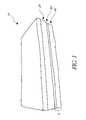
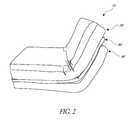
- FIG. 1illustrates a perspective view of one embodiment of a climate controlled adjustable bed configured to recline shown in a normal, non-reclined position
- FIG. 2illustrates the bed of FIG. 1 in a reclined (e.g., non-flat) position
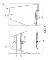
- FIG. 3illustrates a perspective view of one embodiment of a primary foundation or lower support member configured for use with the movable climate controlled bed of FIGS. 1 and 2 ;
- FIG. 4illustrates different top perspective views of one embodiment of an intermediate support member or interlay component configured for use with the movable climate controlled bed of FIGS. 1 and 2 ;
- FIG. 5illustrates different top perspective views of the intermediate support member or interlay component of FIG. 4 secured to the foundation or lower support member of FIG. 3 , according to one embodiment
- FIG. 6illustrates different views of fluid passage openings of a mattress or other upper portion of the climate controlled bed of FIGS. 1 and 2 in relation to corresponding fluid openings and passages of the primary and secondary foundations (e.g., a foundation and an interlay component);
- the primary and secondary foundationse.g., a foundation and an interlay component
- FIG. 7Billustrates a perspective view of one embodiment of an adjustable or reclinable climate controlled bed comprising an interlay component
- FIG. 8illustrates a partial perspective view of one embodiment of a climate controlled bed comprising one or more interlay components
- FIGS. 10A and 10Billustrate bottom and top views, respectively, of the interlay or inlay component of FIG. 9 ;
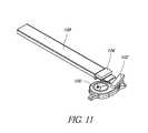
- FIG. 11illustrates a perspective view of one embodiment of a fluid module assembly configured for use with an interlay or inlay component of a climate controlled bed;
- FIG. 12illustrates a top perspective view of one embodiment of a climate controlled bed comprising two interlay or inlay components positioned immediately next to each other above a foundation;
- FIG. 13illustrates a partial bottom view of one embodiment of an interlay or inlay component with a fluid module visible through a window or other opening;
- FIG. 14illustrates a top perspective view of one embodiment of a foundation for a fixed (non-adjustable) bed configured to support one or more interlay or inlay components;
- FIG. 15illustrates a bottom perspective view of one embodiment of a slotted foundation for an adjustable (e.g., reclinable or otherwise movable) bed configured to receive and support one or more interlay or inlay components;
- an adjustablee.g., reclinable or otherwise movable
- FIG. 16Aillustrates a bottom view of an interlay or inlay component configured for use in a climate controlled bed according to another embodiment
- FIG. 16Billustrates a top perspective view of the interlay or inlay component of FIG. 16A ;
- FIG. 17illustrates a bottom view of another embodiment of an interlay or inlay component configured for use in a climate controlled bed
- FIG. 18illustrates a top perspective view of one embodiment of a climate controlled bed having conduits (e.g., couplings, fittings, etc.) positioned at least partially within the openings of the interlay or inlay component;
- conduitse.g., couplings, fittings, etc.
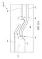
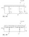
- FIGS. 19A and 19Bschematically illustrate cross-sectional views of a mattress or upper portion of a climate controlled bed according to certain embodiments.
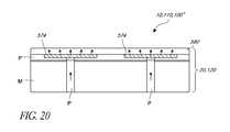
- FIG. 20schematically illustrates a cross-sectional view of a mattress or upper portion of a climate controlled bed according to another embodiment.
- This applicationis generally directed to climate control systems for beds or other seating assemblies.
- the climate control system and the various systems and features associated with itare described herein in the context of bed assemblies (e.g., air chamber beds, adjustable beds, inner-spring beds, spring-free beds, memory foam beds, full foam beds, hospital beds, other medical beds, futons, sofas, reclining chairs, etc.) because they have particular utility in that context.
- bed assembliese.g., air chamber beds, adjustable beds, inner-spring beds, spring-free beds, memory foam beds, full foam beds, hospital beds, other medical beds, futons, sofas, reclining chairs, etc.
- climate control system and the methods described herein, as well as their various systems and featurescan be used in other contexts as well, such as, for example, but without limitation, seat assemblies for automobiles, trains, planes, motorcycles, buses, other types of vehicles, wheelchairs, other types of medical chairs, beds and seating assemblies, sofas, task chairs, office chairs, other types of chairs and/or the like.
- the members 40 , 60can be held relative to each other using one or more attachment devices or methods, such as, for example, stitching, zippers, hook-and-loop connections, buttons, straps, bands, other fasteners, adhesives and/or the like.
- attachment devices or methodssuch as, for example, stitching, zippers, hook-and-loop connections, buttons, straps, bands, other fasteners, adhesives and/or the like.
- the lower portion 40can include more or fewer members or components, as desired or required.
- the adjustable bed 10can be selectively moved (e.g., reclined) such that one portion of the assembly is angled relative to one or more other portions of the assembly.
- the bed 10can be angled, reclined and/or otherwise moved with the assistance of one or more motors, actuators and/or other mechanical, electromechanical, pneumatic or other type of device.
- the lower support member or foundation (e.g., primary foundation) 40can comprise a plurality of segmented sections 42 that are configured to move relative to each other to accommodate movement of the adjustable bed during use.
- the assembly 10 of FIGS. 1 and 2comprises a lower support member 40 having a total of seven segmented sections 42 .
- the number of sections 42can be greater or less than seven (e.g., 2, 3, 4, 5, 6, 8, 9, 10, more than 10, etc.), as desired or required.
- These segmented sections 42provide the bed assembly 10 with the necessary flexibility and/or bendability as the adjustable bed is moved between different positions or configurations during use.
- Adjacent segmented sections 42can be separated by gaps, spaces or other joints 44 that are configured to permit one section 42 to angle or other move relative to the adjacent section 42 .
- the amount of permitted movement between adjacent sections 42can be selected based on one or more factors, such as, for example, the size of the sections, the size of the bed assembly 10 , the amount flexibility or bendability required or desired for the assembly and/or the like.
- the sections 42 that comprise the lower support member 40can include one or more openings or passages 48 .
- Air or other fluids delivered by one or more fluid modulescan be selectively delivered through the passages 48 to transfer such air or other fluids from the fluid modules, at least partially through the lower portion L and/or the upper portion 20 of the bed assembly 10 , e.g., toward one or more occupants positioned on the assembly.
- a fluid modulecan include a fluid transfer device (e.g., blower, fan, etc.), a thermal conditioning device (e.g., a Peltier device, other thermoelectric device or TED, a convective heater, a heat pump, another type of heating and/or cooling device or component, etc.), a dehumidifier and/or any other type of conditioning device.
- a fluid transfer devicee.g., blower, fan, etc.
- a thermal conditioning devicee.g., a Peltier device, other thermoelectric device or TED, a convective heater, a heat pump, another type of heating and/or cooling device or component, etc.
- a dehumidifiere.g., any other type of conditioning device.
- Some embodiments of a fluid modulecomprise one or more conduits to place the various components of the fluid module and other portions of the bed 10 in fluid communication with each other and/or the like.
- the various components of a fluid modulecan be included within a single housing or can
- thermally or environmentally conditioned aircan be directed toward the lower portion L and/or the upper portion 20 by the one or more fluid modules.
- the fluid modulecan include a heating, cooling and/or other conditioning (e.g., temperature, humidity, etc.) device that is not a thermoelectric device.
- a conditioning devicecan include a convective heater, a heat pump, a dehumidifier and/or the like.
- thermoelectric devicesconvective heaters and other conditioning devices
- U.S. patent application Ser. No. 11/047,077filed on Jan. 31, 2005 and issued as U.S. Pat. No. 7,587,901 on Sep. 15, 2009
- U.S. patent application Ser. No. 12/049,120filed Mar. 14, 2008 and issued as U.S. Pat. No. 8,143,554 on Mar. 27, 2012
- U.S. patent application Ser. No. 12/695,602filed Jan. 28, 2010 and published as U.S. Publication No. 2010/0193498 on Aug. 5, 2010, and U.S. patent application Ser. No. 13/289,923, filed Nov. 4, 2011 and published as U.S. Publication No. 2012/0114512 on May 10, 2012 the entireties of all of which are hereby incorporated by reference herein and made a part of the present application.
- one or more fluid modulesare fixedly or removably secured to the rear surface of the lower support member 40 .
- a fluid modulecan be attached to a rear surface (e.g., the surface that generally faces toward the ground when the bed 10 is generally horizontally positioned) and/or to the segmented section 42 so as to generally or completely align an outlet of the fluid module to the fluid passage or opening 48 .
- air or other fluidcan be selectively delivered through the lower support member 40 (e.g., toward and through the intermediate support member 60 and the upper support member or mattress 20 of the bed assembly 10 ).
- each fluid passage or opening 48is placed in fluid communication with at least one fluid module.
- the slotted openings 64 of the intermediate support member 60can be configured to pass only partially through a vertical section (e.g., generally perpendicular to the ground when the bed 10 is generally horizontally positioned) of the member 60 .
- a lower section 62 of the intermediate support member or interlay 60(which, in some embodiments, comprises one or more slotted openings 64 ) can be selectively covered by an upper, generally continuous section 68 .
- the upper section 68can comprise open foam and/or another type of air-permeable or partially air-permeable material to allow air or other fluid to freely pass from the slotted opening 64 to the top of the intermediate support member 60 via the upper section 68 .
- the intermediate support member or inlay component 60comprises one or more slotted openings, passages or other cavities 64 that extend through the entire vertical portion of the member 60 .
- FIG. 5illustrates a perspective top view of one embodiment of the intermediate support member, inlay or interlay component 60 positioned and secured relative to a foundation 40 .
- the slotted openings or cavities 64 of the intermediate support member 60can generally align with (e.g., at least longitudinally) one or more of the fluid passages 48 of the lower support member or foundation 40 .
- a slotted opening 64can be in fluid communication with a fluid passage 48 and the fluid module to which the fluid passage is fluidly coupled. Accordingly, air or other fluid delivered by the fluid modules can be advantageously transferred to one or more of the slotted openings or passages 64 of the intermediate support member, interlay or inlay 60 .
- the upper portioncan comprise one or more materials to provide the desired or required firmness, feel, comfort and/or other characteristics to the bed assembly 10 .
- the bed 10can include one or more layers of foam (e.g., viscoelastic foam, polyurethane foam, coconut foam, memory foam, other thermoplastics or cushioning materials and/or the like), latex, other thermoplastic materials, pillow layers, other comfort layers and/or the like.
- the bedcomprises springs (e.g., coil springs, air springs, etc.), air or fluid tubes or containers and/or any other component, device or feature.
- an intermediate layercomprises one or more fluid channels or ducts (e.g., for receiving and moving air, other gases and/or other fluids to specific locations of the bed or other seating assembly), spaces configured to receive and house a fluid module (e.g., a blower or other fluid transfer device, a thermoelectric device, convective heater and/or any other heating, cooling or ventilation device, etc.), wiring, wire harnesses and/or other electrical components, sensors and/or the like.
- a fluid modulecan comprise one or more portions.
- the intermediate or inlay layerincludes one or more fluid channels configured to permit fluid (e.g., heated, cooled or ventilated fluid discharged by a fluid module, waste fluid, etc.). Accordingly, such channels or other passages are in fluid communication with one or more fluid modules.
- a fluid modulecan include a fluid transfer device (e.g., fan or blower), a thermal conditioning device (e.g., a thermoelectric device, a convective heater, another type of fluid heating or cooling device, etc.), one or more sensors (e.g., temperature sensors, humidity sensors, condensation sensors, etc.), controllers and/or the like.
- the intermediate layer or inlaycan be shaped, sized, designed and otherwise configured to accommodate one or more fluid modules directly therein.
- Such a configurationcan provide one or more benefits and other advantages to the climate controlled seating assembly, such as, for example, space saving advantages, simplification of the assembly's overall design, quieter, smoother and/or otherwise more enhanced or improved operation of the system (e.g., reduced noise and/or vibration created by the operating fluid modules, better fluid transfer to, through and away from the assembly, etc.) and/or the like.
- the inlaycan comprise one or more channels that receive and route to select portions of the inlay, and thus the seating assembly, waste air created by one or more thermoelectric devices or other thermal conditioning devices of the assembly's climate control system.
- the intermediate layer or inlaycan also be used to strategically and advantageously accommodate one or more wire harnesses for placing the fluid modules and/or other electric components of the system in power and/or data communication with a power supply, controller and/or the like.
- the intermediate layer or inlay 160can include more (e.g., three, four, more than four, etc.) or fewer (e.g., only one) components, depending on the size of the bed or other seating assembly and/or as otherwise desired or required.
- FIG. 9One embodiment of an intermediate layer, interlay or inlay 160 , 160 ′ configured for use in a climate controlled seating assembly (such as the fixed or adjustable beds of FIGS. 7A and 7B , respectively) is illustrated in FIG. 9 .
- the inlay 160 , 160 ′(or a component thereof) can comprise one or more fluid modules 100 . Therefore, for a bed assembly that includes two inlay components, such as the one illustrated in FIG. 8 , a total of four fluid modules are used.
- the depicted embodiment of the inlay componentcomprises a total of two fluid modules, spaced apart from one another. In other embodiments, the quantity, location, orientation, spacing and/or other details regarding the fluid modules can vary, as desired or required.
- an intermediate layer or inlaycan include fewer (e.g., one) or more (e.g., three, four or more) fluid modules, depending on the size of the bed or other seating assembly, the desired environmental conditioning and/or one or more other factors or considerations.
- the inlet channelscan be routed along a different portion of the intermediate layer or inlay 160 , 160 ′ (e.g., the head-side or foot-side of the layer), either in lieu of or in additional to the sides, as desired or required.
- the channels or passages of the interlay or inlay componentscomprise a generally rectangular cross-sectional shape.
- the cross-sectional shape of the channelscan vary (e.g., semi-circular, partially oval or circular, triangular, other polygonal, irregular, etc.), as desired or required.
- one or more of the channelscan include a lining, coating and/or other feature thereon (e.g., to improve air impermeability, reduce head loss and/or for any reason, purpose or goal).
- only a portion of the air that is delivered to the fluid modulesoriginates from the inlet channels of the inlay or interlay component 160 , 160 ′.
- the inlet channels 122 , 124 of the inlayare configured to serve merely as supplemental conduits of inlet air.
- one reason for thisis because the edges of the interlay inlet channels can become blocked, at least partially, by blankets, sheets or other portions of a bed or other items placed adjacent to the bed (e.g., chests, other furniture, etc.).
- the bottom of the bed assemblycan provide a more reliable and consistent source of inlet air to the fluid modules.
- the interlay or interlay component 160 , 160 ′comprises one or more recesses that are sized, shaped and otherwise configured to accommodate fluid modules.
- Such recesses or portions of the interlay componentare advantageously designed so that when a fluid module is positioned therein, the inlets of the fluid modules are generally aligned and/or otherwise placed in fluid communication with the inlet channels 122 , 124 of the interlay and/or other inlet openings (e.g., windows or other accessways 182 along the rear side of the interlay).
- the inlay or interlay componentscan comprise one or more flexible, rigid and/or semi-rigid materials, such as, for example, foam (e.g., open cell foam, closed cell foam, etc.), other plastic materials, metals, alloys, other composite or natural materials, etc.).
- the interlaycan be configured to be generally flexible within a desired range for use in adjustable beds or other movable seating assemblies.
- the interlay componentscan be air permeable (partially or completely) or air impermeable, as desired or required.
- the fluid modules 100 that are positioned within the interlay component 160 , 160 ′are provided as part of a larger module assembly.
- the depicted assemblycomprises a fluid module 100 (e.g., blower or other fluid transfer device, thermoelectric device, convective heater or other thermal or environmental conditioning device, etc.) and a duct or other fluid conduit 108 in fluid communication with an outlet (e.g., the waste outlet) of the module.
- a fluid module 100e.g., blower or other fluid transfer device, thermoelectric device, convective heater or other thermal or environmental conditioning device, etc.
- a duct or other fluid conduit 108in fluid communication with an outlet (e.g., the waste outlet) of the module.
- the module assemblycan also include one or more guides or separation members 102 , 104 that are configured to provide a necessary or desired clearance between the fluid module and the bottom of the interlay component once the assembly has been properly positioned within the interlay and the interlay has been placed between a foundation and a mattress or other upper portion.
- the module assembly illustrated in FIG. 11can be sized, shaped and otherwise configured to be placed within a corresponding module recess, channel recess and/or other portion of the interlay component, as shown in FIG. 9 .
- one or more fluid modules 100can be positioned directly into the inlay or interlay component 160 , 160 ′.
- the inlay or interlay component 160 , 160 ′can comprise one or more slots 132 , gaps, recesses or other spaces configured to accommodate wire harnesses, wires, other electrical connections, sensors, struts or other structural reinforcing members and/or any other device or component.
- Such openings 132can allow for wire harnesses, other electrical connectors and/or any other device or member to be neatly and discretely positioned in the inlay component (e.g., to provide power to the fluid modules, to place the fluid modules, components thereof and/or other components, such as, sensors, controllers and/or the like in data communication with one another or with other portions of the assembly's climate control system, etc.).
- the channels, wire harness slots, fluid module recesses and/or other openings of the inlay component 160 , 160 ′are manufactured into the desired shape using molding techniques (e.g., injection molding). Alternatively, however, such openings can be created by selectively removing portions of a base material (e.g., larger foam block or layer). In other embodiments, one or more layers or portions can be selectively attached to a base layer 161 so as to create the channels 122 , 124 , 112 , 114 , recesses, slots 132 and/or other openings within the inlay component, as desired or required. For example, smaller foam components can be secured to one or more base foam layers 161 using adhesives, fasteners and/or any other type of connection method or device.
- one or more coverings or outer layers 180can be positioned at least partially along the outside of the inlay or interlay component 160 , 160 ′.
- a generally air impermeable or partially air impermeable layer 184e.g., fabric, coating, etc.
- such a layer 184comprises an anti-skid or anti-slip layer that helps to maintain the position of the inlay component relative to the foundation on which it is positioned after assembly and during use.
- the layercan include one or more windows or other openings 182 that are aligned (at least partially) with the fluid modules to advantageously permit inlet air to be transferred to the fluid modules from an area below the inlay component 160 , 160 ′ (e.g., within or near the foundation).
- the top surface 188 of the component 160 , 160 ′can also include one or more non-skid layers to help maintain the position of the inlay component relative to the mattress or upper portion of the bed assembly.
- the discharge end 190 of each of the fluid modules 100 included within the inlay componentcan be directed to corresponding outlets 190 that extend to or near (or in some embodiments, through and above) the top of the inlay component (e.g., through one or more layers or other coverings). In some embodiments, such outlets 190 are oriented so as to generally align with internal passages of the adjacent mattress or other upper portion of the bed assembly (see, e.g., FIGS. 19A , 19 B and 20 ).
- air or other fluid discharged by the fluid modules of the inlay component 160 160 ′can be advantageously delivered through fluid passages of the mattress and toward the top of the bed assembly (e.g., toward one or more seated occupants through one or more fluid distribution members or portions located along or near the top of the mattress).
- the outletsare generally aligned along a longitudinal axis 192 of the inlay.
- two or more of the outletscan be offset form each other, as desired or required.
- FIG. 13illustrates one embodiment of a window or other opening 182 along the back or rear side (e.g., bottom, when the inlay is positioned on a bed assembly) 184 of an inlay component 160 , 160 ′.
- the window 182comprises a layer of mesh and/or one or more other air permeable materials or configurations to permit air or other fluid to freely flow from the area beneath the inlay 160 , 160 ′ to the inlet of the fluid module positioned within the inlay component.
- the layer or covering along the rear side of the inlay adjacent the window or opening 182can be completely or partially air impermeable.
- any layer or other covering that is positioned completely or partially around a interlay, inlay or intermediate layer or componentcan be configured to include an air permeable or partially air permeable portion (e.g., permeable fabric or other layer, mesh or other layer comprising one or more fluid openings or passages, etc.) at locations where the channels (e.g., inlet channels, waste channels, etc.) terminate along the ends or edges of the inlay.
- an air permeable or partially air permeable portione.g., permeable fabric or other layer, mesh or other layer comprising one or more fluid openings or passages, etc.
- the channelse.g., inlet channels, waste channels, etc.
- openings 148are sized, shaped, located and otherwise configured to align or substantially align with adjacent windows or other openings 182 along the rear surface of the inlay 160 , 160 ′. Accordingly, air or other fluid can be drawn into the fluid modules located within or near the inlay components from the area within, below and/or near the foundation 140 .
- FIG. 15illustrates a rear, perspective view of a foundation or lower portion 140 ′ configured to be used in an adjustable climate controlled bed assembly.
- the foundation 140 ′can include one or more slots, gaps or spaces 144 that separate adjacent portions or sections 142 of the foundation.
- adjacent sections 142are connected to each other using one or more fasteners (e.g., straps, belts, wires, mechanical fasteners, etc.) that provide the required or desired flexibility to the foundation (e.g., by allowing relative rotation of adjacent sections or portions).
- the adjustable bedcan be permitted to rotate during use as a user changes the angle of the bed.
- the foundation 140 ′comprises a total of five sections 142 , some of which vary in shape.
- the number, length, spacing, relative angular flexibility and/or characteristics of the adjustable foundationcan vary, as desired or required by a particular application or use.
- the use of a slotted foundationcan facilitate the delivery of air other fluid from the area within or below the foundation to the fluid modules positioned within one or more interlay or inlay components.
- the slots or openings of the foundationcan be located along or near adjacent windows or openings 182 along the lower surface of an inlay so as to provide access to the corresponding fluid module intake.
- Such slotscan either replace or supplement other openings within a foundation (see, for example, the dedicated openings 148 of the foundation of FIG. 14 ).
- FIGS. 16A and 16Billustrate different views of another embodiment of an intermediate layer or inlay component 260 , 260 ′ configured for use in a climate controlled bed or other seating assembly.
- the depicted inlay component 260 , 260 ′can be used either in fixed or adjustable bed assemblies.
- the inlay component 260 , 260 ′comprises two fluid modules 100 .
- Inlet channels 222 , 224 formed within the inlaycan help deliver ambient air toward the inlet of each fluid module.
- Such a stream of inlet aircan supplement or replace air drawn from any open area beneath the inlay (e.g., through any openings or fluid passages formed within the inlay and/or the foundation below and in the vicinity of the fluid modules 100 ).
- waste channels 212 , 214 formed within the inlaycan be used to transfer such waste air to the outside of the inlay and the bed assembly.
- the inlet channelsextend to the foot-end of the bed or other seating assembly, while the waste channels extend to the head-end of the assembly.
- the orientation of the channelscan be reversed (e.g., so the waste air is transferred to the foot end of the bed when the fluid modules are in use).
- the channelscan begin and/or terminate along the sides of the inlay, either in lieu of or in addition to the head-end or foot-end, as desired or required.
- one or more channels of an inlaycan meet, combine or otherwise be placed in fluid communication with one another.
- the inlay embodiment illustrated in FIG. 17comprises inlet channels 322 , 324 that branch off and terminate along two different portions of the inlay edge.
- inlet channel 322extends to both the foot-end and a side of the inlay or interlay component 360 , 360 ′.
- the waste channels 312 , 314 depicted in FIG. 17are generally combined (e.g., hydraulically) and extend to three different locations along the head end of the inlay.
- the outletse.g., discharge ends of the fluid modules, conduits in fluid communication with the discharge ends of the fluid modules, etc.
- the outletsare advantageously adapted to generally align with corresponding passages of the adjacent mattress or upper portion of the bed assembly.
- a tube or other conduit 194can be positioned within each fluid outlet or opening 190 along the top surface 188 of the inlay.
- conduits 194are shaped, sized and otherwise configured to remain firmly in place within each outlet or opening 190 and to extend upwardly, at least slightly, relative to the top surface of the inlay.
- the mattress or upper portion of the bed assemblycan be positioned over the inlay so that the conduits are inserted within corresponding internal passages of the mattress. This can help ensure that the inlay or interlay components are properly aligned with the mattress or upper portion of the bed or other seating assembly. Further, such a configuration can help prevent relative movement of the inlay and the mattress during use, either in lieu of or in addition to using anti-skid surfaces, layers, components or features between such components.
- fluidcan be delivered from one or more of the fluid modules 100 positioned within the inlay through corresponding internal passages P of the mattress. Air or other fluid is transferred through the passages P to one or more fluid distribution members or layers F (e.g., spacer fabric, open cell foam, other air permeable structures, layers or members, etc.) located along or near the top of the mattress or upper portion 20 , 120 of the bed assembly 10 , 110 , 110 ′. As shown, one or more air permeable layers T can be located above the fluid distribution members or layers F, as desired or required.
- fluid distribution members or layers Fe.g., spacer fabric, open cell foam, other air permeable structures, layers or members, etc.
- FIG. 20Another embodiment of a mattress or upper portion 20 , 120 of a bed assembly 10 , 110 , 110 ′ is schematically illustrated in FIG. 20 .
- the mattress 20 , 120can include two or more conditioning zones (e.g., using hydraulically distinct portions 574 within the fluid distribution members or layers F).
- the various embodiments disclosed herein, including the variations of the intermediate layers (e.g., inlays, interlays or components thereof), foundations and/or the likecan be incorporated into any type of climate controlled bed or other seating assembly, such as, for example, foam beds (e.g., full foam beds), spring beds, air chamber beds, futons or other material-filled beds, waterbeds, latex beds, air toppers and the like).
- foam bedse.g., full foam beds
- spring bedse.g., air chamber beds, futons or other material-filled beds, waterbeds, latex beds, air toppers and the like.
Landscapes
- Mattresses And Other Support Structures For Chairs And Beds (AREA)
Abstract
Description
Claims (20)
Priority Applications (2)
| Application Number | Priority Date | Filing Date | Title |
|---|---|---|---|
| US13/774,947US9125497B2 (en) | 2007-10-15 | 2013-02-22 | Climate controlled bed assembly with intermediate layer |
| US14/812,775US9974394B2 (en) | 2007-10-15 | 2015-07-29 | Climate controlled bed assembly with intermediate layer |
Applications Claiming Priority (4)
| Application Number | Priority Date | Filing Date | Title |
|---|---|---|---|
| US11/872,657US8065763B2 (en) | 2006-10-13 | 2007-10-15 | Air conditioned bed |
| US12/505,355US8181290B2 (en) | 2008-07-18 | 2009-07-17 | Climate controlled bed assembly |
| US201261602332P | 2012-02-23 | 2012-02-23 | |
| US13/774,947US9125497B2 (en) | 2007-10-15 | 2013-02-22 | Climate controlled bed assembly with intermediate layer |
Related Child Applications (1)
| Application Number | Title | Priority Date | Filing Date |
|---|---|---|---|
| US14/812,775ContinuationUS9974394B2 (en) | 2007-10-15 | 2015-07-29 | Climate controlled bed assembly with intermediate layer |
Publications (2)
| Publication Number | Publication Date |
|---|---|
| US20130269106A1 US20130269106A1 (en) | 2013-10-17 |
| US9125497B2true US9125497B2 (en) | 2015-09-08 |
Family
ID=49323739
Family Applications (2)
| Application Number | Title | Priority Date | Filing Date |
|---|---|---|---|
| US13/774,947ActiveUS9125497B2 (en) | 2007-10-15 | 2013-02-22 | Climate controlled bed assembly with intermediate layer |
| US14/812,775Active2033-06-08US9974394B2 (en) | 2007-10-15 | 2015-07-29 | Climate controlled bed assembly with intermediate layer |
Family Applications After (1)
| Application Number | Title | Priority Date | Filing Date |
|---|---|---|---|
| US14/812,775Active2033-06-08US9974394B2 (en) | 2007-10-15 | 2015-07-29 | Climate controlled bed assembly with intermediate layer |
Country Status (1)
| Country | Link |
|---|---|
| US (2) | US9125497B2 (en) |
Cited By (47)
| Publication number | Priority date | Publication date | Assignee | Title |
|---|---|---|---|---|
| US20140237726A1 (en)* | 2013-02-28 | 2014-08-28 | Hill-Rom Services, Inc. | Topper for a patient surface |
| US9335073B2 (en) | 2008-02-01 | 2016-05-10 | Gentherm Incorporated | Climate controlled seating assembly with sensors |
| US9445524B2 (en) | 2012-07-06 | 2016-09-13 | Gentherm Incorporated | Systems and methods for thermoelectrically cooling inductive charging stations |
| US9603459B2 (en) | 2006-10-13 | 2017-03-28 | Genthem Incorporated | Thermally conditioned bed assembly |
| US9622588B2 (en) | 2008-07-18 | 2017-04-18 | Gentherm Incorporated | Environmentally-conditioned bed |
| US9662962B2 (en) | 2013-11-05 | 2017-05-30 | Gentherm Incorporated | Vehicle headliner assembly for zonal comfort |
| US9685599B2 (en) | 2011-10-07 | 2017-06-20 | Gentherm Incorporated | Method and system for controlling an operation of a thermoelectric device |
| US9814641B2 (en) | 2009-08-31 | 2017-11-14 | Genthrem Incorporated | Climate-controlled topper member for beds |
| US9857107B2 (en) | 2006-10-12 | 2018-01-02 | Gentherm Incorporated | Thermoelectric device with internal sensor |
| US9888782B1 (en)* | 2017-01-27 | 2018-02-13 | Eastern Sleep Products Company | Temperature controlled mattress system |
| US9974394B2 (en) | 2007-10-15 | 2018-05-22 | Gentherm Incorporated | Climate controlled bed assembly with intermediate layer |
| US9989267B2 (en) | 2012-02-10 | 2018-06-05 | Gentherm Incorporated | Moisture abatement in heating operation of climate controlled systems |
| US10005337B2 (en) | 2004-12-20 | 2018-06-26 | Gentherm Incorporated | Heating and cooling systems for seating assemblies |
| US20180271300A1 (en)* | 2017-03-22 | 2018-09-27 | Dong Guan Aconic Fabric Co., Ltd | Air-conditioned mattress |
| US10160356B2 (en) | 2014-05-09 | 2018-12-25 | Gentherm Incorporated | Climate control assembly |
| US10219323B2 (en) | 2014-02-14 | 2019-02-26 | Genthrem Incorporated | Conductive convective climate controlled seat |
| US10258163B2 (en) | 2016-04-04 | 2019-04-16 | Ashley Furniture Industries, Inc. | Mattress permitting airflow for heating and cooling |
| US10288084B2 (en) | 2010-11-05 | 2019-05-14 | Gentherm Incorporated | Low-profile blowers and methods |
| USRE47574E1 (en) | 2006-05-31 | 2019-08-20 | Gentherm Incorporated | Structure based fluid distribution system |
| US10390628B2 (en) | 2017-09-01 | 2019-08-27 | William Pisani | Instant hand-held bed sheet warmer |
| US10405667B2 (en) | 2007-09-10 | 2019-09-10 | Gentherm Incorporated | Climate controlled beds and methods of operating the same |
| US10589647B2 (en) | 2013-12-05 | 2020-03-17 | Gentherm Incorporated | Systems and methods for climate controlled seats |
| US10827845B2 (en) | 2017-02-24 | 2020-11-10 | Sealy Technology, Llc | Support cushions including a support insert with a bag for directing air flow, and methods for controlling surface temperature of same |
| US10991869B2 (en) | 2018-07-30 | 2021-04-27 | Gentherm Incorporated | Thermoelectric device having a plurality of sealing materials |
| USD919333S1 (en) | 2019-08-27 | 2021-05-18 | Casper Sleep Inc. | Mattress |
| US11033058B2 (en) | 2014-11-14 | 2021-06-15 | Gentherm Incorporated | Heating and cooling technologies |
| USD927889S1 (en) | 2019-10-16 | 2021-08-17 | Casper Sleep Inc. | Mattress layer |
| US11103081B2 (en) | 2016-07-27 | 2021-08-31 | Ppj, Llc | Climate controlled mattress system |
| US11116326B2 (en) | 2017-08-14 | 2021-09-14 | Casper Sleep Inc. | Mattress containing ergonomic and firmness-regulating endoskeleton |
| US20210307530A1 (en)* | 2020-04-07 | 2021-10-07 | Lg Electronics Inc. | Bed |
| US11152557B2 (en) | 2019-02-20 | 2021-10-19 | Gentherm Incorporated | Thermoelectric module with integrated printed circuit board |
| US11160386B2 (en) | 2018-06-29 | 2021-11-02 | Tempur World, Llc | Body support cushion with ventilation system |
| US11202517B2 (en) | 2014-04-21 | 2021-12-21 | Casper Sleep Inc. | Mattress |
| US11241100B2 (en) | 2018-04-23 | 2022-02-08 | Casper Sleep Inc. | Temperature-regulating mattress |
| US11311111B2 (en) | 2020-04-06 | 2022-04-26 | Purple Innovation, Llc | Ventilated mattresses |
| US11559421B2 (en) | 2015-06-25 | 2023-01-24 | Hill-Rom Services, Inc. | Protective dressing with reusable phase-change material cooling insert |
| US11583437B2 (en) | 2018-02-06 | 2023-02-21 | Aspen Surgical Products, Inc. | Reusable warming blanket with phase change material |
| US11639816B2 (en) | 2014-11-14 | 2023-05-02 | Gentherm Incorporated | Heating and cooling technologies including temperature regulating pad wrap and technologies with liquid system |
| US11857004B2 (en) | 2014-11-14 | 2024-01-02 | Gentherm Incorporated | Heating and cooling technologies |
| US11925271B2 (en) | 2014-05-09 | 2024-03-12 | Sleepnea Llc | Smooch n' snore [TM]: devices to create a plurality of adjustable acoustic and/or thermal zones in a bed |
| US11993132B2 (en) | 2018-11-30 | 2024-05-28 | Gentherm Incorporated | Thermoelectric conditioning system and methods |
| US12053096B2 (en) | 2014-10-16 | 2024-08-06 | Sleep Number Corporation | Bed with integrated components and features |
| US12089746B2 (en) | 2017-08-23 | 2024-09-17 | Sleep Number Corporation | Fluid system for a bed |
| US12193575B2 (en) | 2020-01-03 | 2025-01-14 | Sleep Number Corporation | Bed microclimate control with preparation cycle |
| US12239232B2 (en) | 2021-03-01 | 2025-03-04 | Sleep Number Corporation | Bed sensors |
| US12383070B2 (en) | 2012-12-27 | 2025-08-12 | Sleep Number Corporation | Distribution pad for a temperature control system |
| US12433421B2 (en) | 2021-10-13 | 2025-10-07 | Sleep Number Corporation | Bed microclimate control using humidity measurements |
Families Citing this family (15)
| Publication number | Priority date | Publication date | Assignee | Title |
|---|---|---|---|---|
| JP5485701B2 (en) | 2007-01-10 | 2014-05-07 | ジェンサーム インコーポレイティド | Thermoelectric element |
| US9105809B2 (en) | 2007-07-23 | 2015-08-11 | Gentherm Incorporated | Segmented thermoelectric device |
| US8893329B2 (en) | 2009-05-06 | 2014-11-25 | Gentherm Incorporated | Control schemes and features for climate-controlled beds |
| US9131780B2 (en) | 2012-02-14 | 2015-09-15 | Hill-Rom Services, Inc. | Topper with preferential fluid flow distribution |
| US10376412B2 (en)* | 2012-07-16 | 2019-08-13 | University of Pittsburgh—of the Commonwealth System of Higher Education | Actively and selectively cooled cushioning surface |
| US9572433B2 (en) | 2012-08-15 | 2017-02-21 | Hill-Rom Services, Inc. | Systems and methods for directing fluid flow in a mattress |
| US9333136B2 (en) | 2013-02-28 | 2016-05-10 | Hill-Rom Services, Inc. | Sensors in a mattress cover |
| NZ722015A (en)* | 2014-01-13 | 2021-09-24 | Bedgear Llc | Ambient bed having a heat reclaim system |
| US20150282631A1 (en)* | 2014-04-08 | 2015-10-08 | Jim Creamer | Temperature Control Pad |
| DE102015112449A1 (en)* | 2015-07-30 | 2017-02-02 | MAQUET GmbH | Device for heating a patient support surface of a surgical table |
| KR102604935B1 (en)* | 2018-12-04 | 2023-11-22 | 엘지전자 주식회사 | Dryer for bed |
| US11497322B2 (en) | 2019-11-15 | 2022-11-15 | Sleep Number Corporation | Zipper mattress attachment |
| KR20210124675A (en)* | 2020-04-07 | 2021-10-15 | 엘지전자 주식회사 | Bed |
| JP7334002B1 (en)* | 2023-02-27 | 2023-08-28 | 株式会社レーベン | mattress |
| US12285111B1 (en) | 2023-12-15 | 2025-04-29 | SENIAH Innovations Group, LLC | Modular mattress system and method |
Citations (266)
| Publication number | Priority date | Publication date | Assignee | Title |
|---|---|---|---|---|
| US96989A (en) | 1869-11-16 | Improved means for ventilating-, cooling-, and warming- beds | ||
| US771461A (en) | 1903-06-08 | 1904-10-04 | William Clifford | Ventilating-fan structure. |
| US2461432A (en) | 1944-05-22 | 1949-02-08 | Mitchell Co John E | Air conditioning device for beds |
| US2462984A (en)* | 1944-10-27 | 1949-03-01 | Horace P Maddison | Air-conditioned mattress |
| US2493067A (en) | 1945-09-08 | 1950-01-03 | Louis J Goldsmith | Mattress |
| US2512559A (en) | 1945-01-18 | 1950-06-20 | Alfred L W Williams | Comfort unit |
| US2782834A (en) | 1955-05-27 | 1957-02-26 | Vigo Benny Richard | Air-conditioned furniture article |
| US2791956A (en) | 1953-12-24 | 1957-05-14 | Maurice C Guest | Ventilated automobile seat pad |
| US2931286A (en) | 1956-09-13 | 1960-04-05 | Sr Walter L Fry | Fluid conduit article of manufacture and combination article of manufacture |
| US2976700A (en) | 1958-05-14 | 1961-03-28 | William L Jackson | Seat structure |
| US3030145A (en) | 1953-08-26 | 1962-04-17 | Kushion Kooler Corp | Ventilating seat pad |
| US3039817A (en) | 1959-06-01 | 1962-06-19 | Don A Taylor | Air intake scoop for ventilating seat cushion |
| FR1327862A (en) | 1962-04-12 | 1963-05-24 | Bedding heaters improvements | |
| US3136577A (en) | 1961-08-02 | 1964-06-09 | Stevenson P Clark | Seat temperature regulator |
| US3137523A (en) | 1963-09-20 | 1964-06-16 | Karner Frank | Air conditioned seat |
| US3209380A (en) | 1964-12-31 | 1965-10-05 | Watsky Benjamin | Rigid mattress structure |
| US3266064A (en) | 1963-03-29 | 1966-08-16 | Figman Murray | Ventilated mattress-box spring combination |
| US3529310A (en) | 1968-03-28 | 1970-09-22 | Giuseppe Olmo Superflexite Spa | Process to ventilate stuffings of cellular material and stuffing actuated with said process |
| US3550523A (en) | 1969-05-12 | 1970-12-29 | Irving Segal | Seat construction for automotive air conditioning |
| US3653083A (en) | 1970-05-11 | 1972-04-04 | Roy Lapidus | Bed pad |
| US3928876A (en)* | 1974-08-19 | 1975-12-30 | Louis J Starr | Bed with circulated air |
| JPS5697416U (en) | 1979-12-26 | 1981-08-01 | ||
| US4413857A (en) | 1979-11-06 | 1983-11-08 | Nissan Motor Co., Ltd. | Seat cover |
| US4423308A (en) | 1981-06-22 | 1983-12-27 | Simmons U.S.A. Corporation | Thermally controllable heating mattress |
| US4563387A (en) | 1983-06-30 | 1986-01-07 | Takagi Chemicals, Inc. | Cushioning material |
| US4671567A (en) | 1986-07-03 | 1987-06-09 | The Jasper Corporation | Upholstered clean room seat |
| US4685727A (en) | 1985-03-28 | 1987-08-11 | Keiper Recaro Gmbh & Co. | Vehicle seat |
| JPS62193457U (en) | 1986-05-30 | 1987-12-09 | ||
| US4712832A (en) | 1985-06-24 | 1987-12-15 | Adriano Antolini | Cover, particularly for vehicle seats |
| US4777802A (en) | 1987-04-23 | 1988-10-18 | Steve Feher | Blanket assembly and selectively adjustable apparatus for providing heated or cooled air thereto |
| US4793651A (en) | 1980-12-22 | 1988-12-27 | Aisin Seiki Kabushiki Kaisha | Heat-retaining air-filled seat cover for lumbar support |
| US4825488A (en) | 1988-04-13 | 1989-05-02 | Bedford Peter H | Support pad for nonambulatory persons |
| US4853992A (en) | 1988-07-22 | 1989-08-08 | Kaung M Yu | Air cooled/heated seat cushion |
| US4905475A (en) | 1989-04-27 | 1990-03-06 | Donald Tuomi | Personal comfort conditioner |
| US4923248A (en) | 1988-11-17 | 1990-05-08 | Steve Feher | Cooling and heating seat pad construction |
| US4981324A (en) | 1989-10-13 | 1991-01-01 | Law Ignace K | Ventilated back-seat support pad particularly for vehicles |
| US4997230A (en) | 1990-01-30 | 1991-03-05 | Samuel Spitalnick | Air conditioned cushion covers |
| US5002336A (en) | 1989-10-18 | 1991-03-26 | Steve Feher | Selectively cooled or heated seat and backrest construction |
| US5016304A (en) | 1988-03-29 | 1991-05-21 | Redactron B.V. | Fluidized bed with moisture removing means |
| US5077709A (en) | 1990-10-15 | 1991-12-31 | Steve Feher | Rotating timepiece dial face construction with included movable decorative objects |
| US5102189A (en) | 1990-12-28 | 1992-04-07 | Tachi-S Co., Ltd. | Ventilated seat |
| JPH04108411A (en) | 1990-08-28 | 1992-04-09 | Matsushita Electric Ind Co Ltd | Bedding device |
| US5106161A (en) | 1989-08-31 | 1992-04-21 | Grammer Ag | Cushion portion for a seat |
| US5117638A (en) | 1991-03-14 | 1992-06-02 | Steve Feher | Selectively cooled or heated seat construction and apparatus for providing temperature conditioned fluid and method therefor |
| US5125238A (en) | 1991-04-29 | 1992-06-30 | Progressive Dynamics, Inc. | Patient warming or cooling blanket |
| GB2251352A (en) | 1990-12-31 | 1992-07-01 | Samsung Electronics Co Ltd | An automatic gain control circuit for a video camera |
| US5265599A (en) | 1992-10-01 | 1993-11-30 | Progressive Dynamics, Inc. | Patient temperature control blanket with controlled air distribution |
| US5335381A (en) | 1993-11-12 | 1994-08-09 | Chang Chung Tai | Bed having a warming device |
| US5367728A (en) | 1993-04-23 | 1994-11-29 | Chang; Ching-Lung | Adjustable ventilation mattress |
| US5372402A (en) | 1993-12-09 | 1994-12-13 | Kuo; Hung-Chou | Air cooled cushion |
| JPH06343664A (en) | 1993-04-22 | 1994-12-20 | Ssi Medical Services Inc | Fluidized patient support system |
| US5382075A (en) | 1993-10-19 | 1995-01-17 | Champion Freeze Drying Co., Ltd. | Chair seat with a ventilation device |
| JPH073403U (en) | 1993-06-24 | 1995-01-20 | 株式会社マック計算センター | Bedding with air-conditioning air outlet |
| US5385382A (en) | 1993-10-06 | 1995-01-31 | Ford Motor Company | Combination seat frame and ventilation apparatus |
| US5416935A (en) | 1993-11-29 | 1995-05-23 | Nieh; Rosa L. | Cushion surface air conditioning apparatus |
| US5419489A (en) | 1994-01-18 | 1995-05-30 | Burd; Alexander L. | Mobile thermostat to control space temperature in the building |
| US5433741A (en) | 1993-10-14 | 1995-07-18 | Truglio; Francis G. | Thermally-interactive backboard |
| US5448788A (en) | 1994-03-08 | 1995-09-12 | Wu; Shuenn-Jenq | Thermoelectric cooling-heating mattress |
| US5473783A (en) | 1994-04-04 | 1995-12-12 | Allen; Randall W. | Air percolating pad |
| US5493742A (en) | 1994-05-10 | 1996-02-27 | Lake Medical Products, Inc. | Ventilating air mattress with an inflating quilted pad |
| US5584084A (en) | 1994-11-14 | 1996-12-17 | Lake Medical Products, Inc. | Bed system having programmable air pump with electrically interlocking connectors |
| US5597200A (en) | 1993-11-22 | 1997-01-28 | Amerigon, Inc. | Variable temperature seat |
| US5613730A (en) | 1995-03-29 | 1997-03-25 | Buie; Dan | Temperature controlled seat cover assembly |
| US5613729A (en) | 1996-01-22 | 1997-03-25 | Summer, Jr.; Charlie B. | Ventilated seat cover apparatus |
| US5626386A (en) | 1996-07-16 | 1997-05-06 | Atoma International, Inc. | Air cooled/heated vehicle seat assembly |
| US5626021A (en) | 1993-11-22 | 1997-05-06 | Amerigon, Inc. | Variable temperature seat climate control system |
| WO1997017930A1 (en) | 1995-11-14 | 1997-05-22 | Jalal Ghazal | Anti-decubitus medical bed |
| JPH09140506A (en) | 1995-11-24 | 1997-06-03 | Yoji Baba | Ventilated bottom board type bed |
| US5640728A (en) | 1993-09-30 | 1997-06-24 | Graebe; Robert H. | Ventilated access interface and cushion support system |
| US5642539A (en) | 1995-11-22 | 1997-07-01 | Kuo; Shang-Tai | Multi-function healthful bed |
| US5645314A (en) | 1995-09-21 | 1997-07-08 | Liou; Yaw-Tyng | Ventilation cushion for chairs |
| US5675852A (en) | 1993-03-08 | 1997-10-14 | Watkins; Charles Eugene | Infant body support pad |
| US5692952A (en) | 1996-02-01 | 1997-12-02 | Chih-Hung; Ling | Air-conditioned seat cushion |
| EP0617946B1 (en) | 1993-03-22 | 1997-12-29 | J O U K - O.M.E. | Fluidised bed mattress for medical use with integrated decontamination means |
| US5715695A (en) | 1996-08-27 | 1998-02-10 | Lord; Kevin F. | Air conditioned seat |
| JPH10165259A (en) | 1996-12-11 | 1998-06-23 | Aisin Seiki Co Ltd | Breathable mattress and ventilation pad |
| EP0862901A1 (en) | 1997-03-05 | 1998-09-09 | Ohmeda Inc. | Thermoelectric infant mattress |
| US5850741A (en) | 1997-06-09 | 1998-12-22 | Feher; Steve | Automotive vehicle steering wheel heating and cooling apparatus |
| WO1999002074A1 (en) | 1997-07-10 | 1999-01-21 | Von Der Heyde Christian P | Apparatus and method for preventing sudden infant death syndrome |
| US5871151A (en) | 1995-12-12 | 1999-02-16 | Fiedrich; Joachim | Radiant hydronic bed warmer |
| US5902014A (en) | 1996-07-17 | 1999-05-11 | Daimler-Benz Aktiengesellschaft | Ventilated vehicle seat with a plurality of miniature ventilators |
| JP2893826B2 (en) | 1990-03-23 | 1999-05-24 | 富士ゼロックス株式会社 | Toner increase control method in image forming apparatus |
| US5921858A (en) | 1996-10-07 | 1999-07-13 | Jc Associates Co., Ltd. | Ventilator for use with vehicle seat |
| US5921314A (en) | 1995-02-14 | 1999-07-13 | W.E.T. Automotive Systems Aktiengesellschaft | Conditioned seat |
| US5924766A (en) | 1997-04-22 | 1999-07-20 | Honda Giken Kogyo Kabushiki Kaisha | Temperature conditioner for vehicle seat |
| US5924767A (en) | 1998-06-18 | 1999-07-20 | Pietryga; Zenon | Ventilated motor vehicle seat cushion |
| US5927817A (en) | 1997-08-27 | 1999-07-27 | Lear Corporation | Ventilated vehicle seat assembly |
| US5934748A (en) | 1997-01-31 | 1999-08-10 | Daimler-Benz Aktiengesellschaft | Vehicle seat with temperature and ventilation control and method of operation |
| US5948303A (en) | 1998-05-04 | 1999-09-07 | Larson; Lynn D. | Temperature control for a bed |
| JPH11266968A (en) | 1998-03-19 | 1999-10-05 | Aisin Seiki Co Ltd | Cold / hot air bedding |
| US5963997A (en) | 1997-03-24 | 1999-10-12 | Hagopian; Mark | Low air loss patient support system providing active feedback pressure sensing and correction capabilities for use as a bed mattress and a wheelchair seating system |
| US6003950A (en) | 1995-09-14 | 1999-12-21 | Walinov Ab | Device for ventilating vehicle chairs |
| US6006524A (en) | 1996-04-18 | 1999-12-28 | Ace Bed Co., Ltd. | Temperature controller for bedding |
| US6019420A (en) | 1998-02-04 | 2000-02-01 | Daimlerchrysler Ag | Vehicle seat |
| EP0878150A3 (en) | 1997-05-17 | 2000-03-15 | Verna Limited | Inflatable support |
| US6048024A (en) | 1995-09-14 | 2000-04-11 | Walinov Ab | Fan device contained in a ventilated vehicle chair |
| US6052853A (en) | 1995-06-07 | 2000-04-25 | Halo Sleep Systems, Inc. | Mattress and method for preventing accumulation of carbon dioxide in bedding |
| US6059018A (en) | 1997-07-14 | 2000-05-09 | Denso Corporation | Vehicle seat air-conditioning system |
| US6062641A (en) | 1997-11-10 | 2000-05-16 | Aisin Seiki Kabushiki Kaisha | Seat apparatus with air flow |
| US6073998A (en) | 1996-10-15 | 2000-06-13 | Siarkowski; Bret | Seat warmer |
| US6079485A (en) | 1997-04-28 | 2000-06-27 | Honda Giken Kogyo Kabushiki Kaisha | Vehicle air-conditioning system with seat heating and cooling device |
| US6085369A (en) | 1994-08-30 | 2000-07-11 | Feher; Steve | Selectively cooled or heated cushion and apparatus therefor |
| US6109688A (en) | 1996-06-07 | 2000-08-29 | Dieter Wurz | Seat, squab or couch upholstery |
| US6119463A (en) | 1998-05-12 | 2000-09-19 | Amerigon | Thermoelectric heat exchanger |
| US6145925A (en) | 1998-12-09 | 2000-11-14 | Daimlerchrysler Ag | Backrest for vehicle seats |
| US6148457A (en) | 1999-06-28 | 2000-11-21 | Sul; Tae Ho | Steam heated bed |
| US6161241A (en) | 1999-05-06 | 2000-12-19 | Milton Zysman | Mattress vents |
| US6171333B1 (en) | 1999-04-29 | 2001-01-09 | Merle D. Nelson | Heating and cooling comforter |
| US6186592B1 (en) | 1998-09-19 | 2001-02-13 | Daimlerchrysler Ag | Heat vehicle seat and method of using same |
| US6189966B1 (en) | 1998-02-03 | 2001-02-20 | Daimlerchrysler Ag | Vehicle seat |
| US6189967B1 (en) | 1999-10-28 | 2001-02-20 | Edward J. Short | Portable air cooled seat cushion |
| US6196627B1 (en) | 1998-02-10 | 2001-03-06 | Daimlerchrysler Ag | Vehicle seat |
| US6206465B1 (en) | 1997-10-15 | 2001-03-27 | Daimlerchrysler Ag | Cushioning for a vehicle seat |
| FR2790430B1 (en) | 1999-03-01 | 2001-05-18 | Faure Bertrand Equipements Sa | VEHICLE SEAT THERMAL REGULATION METHOD AND SYSTEM |
| US6263530B1 (en) | 1996-09-24 | 2001-07-24 | Steve Feher | Selectively cooled or heated cushion and apparatus therefor |
| WO2001084982A1 (en) | 2000-05-11 | 2001-11-15 | Halo Innovations, Inc. | Ventilated sleep devices |
| US6341395B1 (en) | 2000-06-20 | 2002-01-29 | Yu-Chao Chao | Ventilating bed cushion |
| WO2002011968A2 (en) | 2000-08-04 | 2002-02-14 | Woodbridge Foam Corporation | Foam element having molded gas passageways and process for production thereof |
| WO2001078643A3 (en) | 2000-04-18 | 2002-02-21 | Hill Rom Services Inc | Pediatric mattress |
| WO2002058165A1 (en) | 2000-12-26 | 2002-07-25 | Cheolhyeon Choi | Coolness and warmth bed for using peltier's effect |
| US6425527B1 (en) | 2001-07-17 | 2002-07-30 | Lewis T. Smole | Temperature control device for sleeping |
| US20020100121A1 (en) | 2001-01-29 | 2002-08-01 | Earnest Kocurek | Cooling cover apparatus |
| US6487739B1 (en) | 2000-06-01 | 2002-12-03 | Crown Therapeutics, Inc. | Moisture drying mattress with separate zone controls |
| US6497720B1 (en) | 1996-08-30 | 2002-12-24 | Augustine Medical, Inc. | Support apparatus with a plurality of thermal zones providing localized cooling |
| US6509704B1 (en) | 1998-01-23 | 2003-01-21 | Comair Rotron, Inc. | Low profile motor |
| US6511125B1 (en) | 2000-09-25 | 2003-01-28 | Timothy D. Gendron | Ventilated seat pad |
| US20030019044A1 (en) | 2000-03-09 | 2003-01-30 | Stefan Larsson | Bed |
| DE10238552A1 (en) | 2001-08-22 | 2003-03-13 | Lear Corp | Climate control system for passenger compartment of vehicle, includes electronic control unit which controls operation of fan heating mechanism and air heating/cooling subsystems based on signals received from sensors |
| US6541737B1 (en) | 1998-11-11 | 2003-04-01 | Daimlerchrysler Ag | Temperature detector for an air-conditioned vehicle seat |
| US6546576B1 (en) | 2001-11-05 | 2003-04-15 | Ku-Shen Lin | Structure of a ventilated mattress with cooling and warming effect |
| US20030070235A1 (en) | 2000-04-14 | 2003-04-17 | Hiroko Suzuki | Warm-air blower for use with air-controlled bedding |
| USRE38128E1 (en) | 1993-11-22 | 2003-06-03 | Amerigon Inc. | Variable temperature seat climate control system |
| US6581224B2 (en)* | 2001-03-06 | 2003-06-24 | Hyun Yoon | Bed heating systems |
| US6581225B1 (en) | 1999-07-02 | 2003-06-24 | Kazumichi Imai | Mattress used for preventing bedsores or the like |
| WO2003051666A1 (en) | 2001-12-19 | 2003-06-26 | Johnson Controls Gmbh | Ventilation system for an upholstery part |
| US6596018B2 (en) | 2000-03-13 | 2003-07-22 | Sakura Alumi Co., Ltd. | Mattress with bedsore preventing function |
| US6598251B2 (en) | 2001-06-15 | 2003-07-29 | Hon Technology Inc. | Body support system |
| US20030145380A1 (en) | 2002-02-06 | 2003-08-07 | Halo Innovations, Inc. | Furniture cover sheet |
| US6604785B2 (en) | 2000-11-01 | 2003-08-12 | Daimlerchrysler Ag | Motor vehicle seat |
| US20030150060A1 (en) | 2001-11-27 | 2003-08-14 | Chiu Kuang Hsing Co., Ltd. | Mattress assembly |
| US6606866B2 (en) | 1998-05-12 | 2003-08-19 | Amerigon Inc. | Thermoelectric heat exchanger |
| US6606754B1 (en) | 1999-03-30 | 2003-08-19 | Gaymar Industries, Inc. | Supported hypo/hyperthermia pad |
| US20030160479A1 (en) | 2002-02-22 | 2003-08-28 | Karl-Heinz Minuth | Motor vehicle seat |
| US6619736B2 (en) | 2000-02-26 | 2003-09-16 | W.E.T. Automotive Systems Ag | Vehicle seat ventilation system |
| US6626488B2 (en) | 2000-10-06 | 2003-09-30 | Daimlerchrysler Ag | Cushion assembly for a motor vehicle seat |
| US6629724B2 (en) | 2001-01-05 | 2003-10-07 | Johnson Controls Technology Company | Ventilated seat |
| US20030188382A1 (en) | 2002-04-03 | 2003-10-09 | Thomas Klamm | Sleeping bag with integral heating duct |
| US6644735B2 (en) | 2000-11-01 | 2003-11-11 | Daimlerchrysler Ag | Automobile seat |
| US20030234247A1 (en) | 2002-06-19 | 2003-12-25 | Stern Lessing S. | Methods and apparatus for a multi-zone blanket |
| US6676207B2 (en) | 2001-02-05 | 2004-01-13 | W.E.T. Automotive Systems Ag | Vehicle seat |
| US6684437B2 (en) | 1995-11-01 | 2004-02-03 | J. Frank Koenig | Sleeping pad, bedding and bumpers to improve respiratory efficiency and environmental temperature of an infant and reduce the risks of sudden infant death syndrome (SIDS) and asphyxiation |
| US6700052B2 (en) | 2001-11-05 | 2004-03-02 | Amerigon Incorporated | Flexible thermoelectric circuit |
| US6711767B2 (en) | 2002-01-30 | 2004-03-30 | Thomas Klamm | Apparatus for warming a bed |
| US6730115B1 (en) | 1996-05-16 | 2004-05-04 | Kci Licensing, Inc. | Cooling system |
| US20040090093A1 (en) | 2002-11-13 | 2004-05-13 | Toshifumi Kamiya | Vehicle seat air conditioning system |
| JP2004174138A (en) | 2002-11-29 | 2004-06-24 | Sharp Corp | Environmental control equipment |
| US6761399B2 (en) | 2001-12-21 | 2004-07-13 | Daimlerchrysler Ag | Motor vehicle seat |
| US6764502B2 (en) | 1999-12-14 | 2004-07-20 | Arizant Healthcare Inc. | High-efficiency cooling pads, mattresses, and sleeves |
| US6772825B2 (en) | 2002-11-04 | 2004-08-10 | Charles A. Lachenbruch | Heat exchange support surface |
| US6782574B2 (en) | 2000-07-18 | 2004-08-31 | Span-America Medical Systems, Inc. | Air-powered low interface pressure support surface |
| US6786545B2 (en) | 2000-11-01 | 2004-09-07 | Daimlerchrysler Ag | Wind protection device for an open motor vehicle |
| US6786541B2 (en) | 2001-01-05 | 2004-09-07 | Johnson Controls Technology Company | Air distribution system for ventilated seat |
| US20040177622A1 (en) | 2003-01-14 | 2004-09-16 | Harvie Mark R. | Personal back rest and seat cooling and heating system |
| US6808230B2 (en) | 2000-05-19 | 2004-10-26 | Daimlerchrysler Ag | Seat module for a vehicle seat which can be actively ventilated and method of making same |
| US6828528B2 (en) | 2001-07-18 | 2004-12-07 | W.E.T. Automotive Systems Ag | Electric circuit to control an air-conditioned seat |
| US20040255364A1 (en) | 2003-06-23 | 2004-12-23 | Steve Feher | Air conditioned helmet apparatus |
| US20050011009A1 (en) | 2003-07-15 | 2005-01-20 | Hsiang-Ling Wu | Ventilation mattress |
| US6855880B2 (en) | 2001-10-05 | 2005-02-15 | Steve Feher | Modular thermoelectric couple and stack |
| US6855158B2 (en)* | 2001-09-11 | 2005-02-15 | Hill-Rom Services, Inc. | Thermo-regulating patient support structure |
| US6857954B2 (en) | 2003-02-28 | 2005-02-22 | Front-End Solutions, Inc. | Portable seat cooling apparatus |
| US6857697B2 (en) | 2002-08-29 | 2005-02-22 | W.E.T. Automotive Systems Ag | Automotive vehicle seating comfort system |
| US6893086B2 (en) | 2002-07-03 | 2005-05-17 | W.E.T. Automotive Systems Ltd. | Automotive vehicle seat insert |
| US6904629B2 (en) | 2002-10-07 | 2005-06-14 | Wan-Ching Wu | Bed with function of ventilation |
| US20050173950A1 (en) | 2003-12-01 | 2005-08-11 | W.E.T. Automotive System Ag | Valve layer for a seat |
| DE10115242B4 (en) | 2001-03-28 | 2005-10-20 | Keiper Gmbh & Co Kg | Vehicle seat with ventilation |
| US6967309B2 (en) | 2000-06-14 | 2005-11-22 | American Healthcare Products, Inc. | Personal warming systems and apparatuses for use in hospitals and other settings, and associated methods of manufacture and use |
| US6976734B2 (en) | 2002-12-18 | 2005-12-20 | W.E.T. Automotive Systems Ag | Vehicle seat and associated air conditioning apparatus |
| US6977360B2 (en) | 2000-12-22 | 2005-12-20 | W.E.T. Automotive Systems Ag | Textile heating device |
| WO2005120295A1 (en) | 2004-06-11 | 2005-12-22 | John Statham | Environmentally conditioned furniture |
| US20050278863A1 (en)* | 2004-06-22 | 2005-12-22 | Riverpark Incorporated | Comfort product |
| US20050285438A1 (en) | 2004-03-31 | 2005-12-29 | Ts Tech Co., Ltd. | Vehicle seat |
| US20050288749A1 (en) | 2004-06-08 | 2005-12-29 | Lachenbruch Charles A | Heat wick for skin cooling |
| US6990701B1 (en) | 2005-08-05 | 2006-01-31 | Vera Litvak | Sectional non-slip mattress |
| US20060053558A1 (en) | 2004-08-27 | 2006-03-16 | Yongfeng Ye | Air mattress |
| US20060087160A1 (en) | 2004-10-25 | 2006-04-27 | Hanh Dong | Apparatus for providing fluid through a vehicle seat |
| US7036575B1 (en) | 2002-03-19 | 2006-05-02 | Rodney James W | Forced air bed warmer/cooler |
| US7040710B2 (en) | 2001-01-05 | 2006-05-09 | Johnson Controls Technology Company | Ventilated seat |
| US7063163B2 (en) | 2003-01-21 | 2006-06-20 | Halliburton Energy Services, Inc. | Multi-layer deformable composite construction for use in a subterranean well |
| US20060130490A1 (en) | 2004-12-20 | 2006-06-22 | Dusko Petrovski | Control system for thermal module vehicle |
| US20060137099A1 (en) | 2004-12-28 | 2006-06-29 | Steve Feher | Convective cushion with positive coefficient of resistance heating mode |
| US20060137358A1 (en) | 2004-12-28 | 2006-06-29 | Steve Feher | Variable temperature cushion and heat pump |
| US7070232B2 (en) | 2002-08-15 | 2006-07-04 | Nhk Spring Co., Ltd. | Breathable seat |
| US7070231B1 (en) | 2005-01-24 | 2006-07-04 | Wong Peter H | Portable seat cooler |
| US20060158011A1 (en) | 2004-11-02 | 2006-07-20 | W.E.T. Automotive Systems Ag | Molded layer for a seat insert |
| US20060162074A1 (en) | 2003-02-04 | 2006-07-27 | Gaby Bader | Device and method for controlling physical properties of a bed |
| US20060197363A1 (en) | 2004-05-25 | 2006-09-07 | John Lofy | Climate controlled seat |
| US7108319B2 (en) | 2001-07-28 | 2006-09-19 | Johnson Controls Gmbh | Air conditioned cushion part for a vehicle seat |
| US20060214480A1 (en) | 2005-03-23 | 2006-09-28 | John Terech | Vehicle seat with thermal elements |
| US7124593B2 (en) | 2003-09-02 | 2006-10-24 | Steve Feher | Temperature conditioning apparatus for the trunk of a human body |
| US7134715B1 (en) | 2000-07-17 | 2006-11-14 | Kongsberg Automotive Ab | Vehicle seat heating arrangement |
| US20060273646A1 (en) | 2005-05-16 | 2006-12-07 | Brian Comiskey | Ventilated headrest |
| US7147279B2 (en) | 2003-06-05 | 2006-12-12 | Igb Automotive Ltd. | Modular comfort assembly for occupant support |
| US20070035162A1 (en) | 2003-03-06 | 2007-02-15 | Christian Bier | Conditioning system for cooling and heating surfaces, particularly automobile seats |
| US20070040421A1 (en) | 2005-08-22 | 2007-02-22 | Lear Corporation | Seat assembly having an air plenum member |
| US7181786B2 (en)* | 2001-08-10 | 2007-02-27 | Guenther Schoettle | Bed compromising an air guiding unit for air-conditioning rooms |
| US20070069554A1 (en) | 2005-03-23 | 2007-03-29 | Brian Comiskey | Seat climate control system |
| US7201441B2 (en) | 2002-12-18 | 2007-04-10 | W.E.T. Automotive Systems, Ag | Air conditioned seat and air conditioning apparatus for a ventilated seat |
| RU2297207C1 (en) | 2006-02-16 | 2007-04-20 | Марат Инокентьевич Югай | Orthopedic medical care and recovery bed |
| US20070138844A1 (en) | 2004-01-26 | 2007-06-21 | Tae-Sook Kim | Buffer cushion for automobiles |
| US20070158981A1 (en) | 2005-11-10 | 2007-07-12 | W.E.T. Automotive Systems, Ag | Vehicle seat with cushioning layer |
| WO2007060371A3 (en) | 2005-11-25 | 2007-07-26 | Oniris | Air conditioned bed comprising a mattress having an air-permeable layer |
| US20070200398A1 (en) | 2006-02-28 | 2007-08-30 | Scott Richard Wolas | Climate controlled seat |
| US20070251016A1 (en) | 2004-12-28 | 2007-11-01 | Steve Feher | Convective seating and sleeping systems |
| US20070262621A1 (en) | 2004-10-25 | 2007-11-15 | Hanh Dong | Apparatus for providing fluid through a vehicle seat |
| US20070261548A1 (en)* | 2006-05-11 | 2007-11-15 | Kci Licensing, Inc., Legal Department, Intellectual Property | Multi-layered support system |
| US20070277313A1 (en) | 2006-05-31 | 2007-12-06 | John Terech | Structure based fluid distribution system |
| US20070296251A1 (en) | 2005-01-18 | 2007-12-27 | W.E.T. Automotive Systems Ag | Device for conducting air in order to provide air conditioning for a body support device |
| US20080028536A1 (en) | 2006-08-04 | 2008-02-07 | Charlesette Hadden-Cook | Mattress with cooling airflow |
| US20080047598A1 (en) | 2006-08-03 | 2008-02-28 | Amerigon Inc. | Thermoelectric device |
| US7338117B2 (en) | 2003-09-25 | 2008-03-04 | W.E.T. Automotive System, Ltd. | Ventilated seat |
| US20080087316A1 (en) | 2006-10-12 | 2008-04-17 | Masa Inaba | Thermoelectric device with internal sensor |
| US7370911B2 (en) | 2003-10-17 | 2008-05-13 | W.E.T. Automotive Systems, Ag | Automotive vehicle seat insert |
| US20080148481A1 (en)* | 2006-10-13 | 2008-06-26 | Amerigon Inc. | Air conditioned bed |
| US20080166224A1 (en) | 2007-01-09 | 2008-07-10 | Steve Craig Giffin | Blower housing for climate controlled systems |
| US20080164733A1 (en) | 2007-01-08 | 2008-07-10 | Giffin Steven C | Clamp for climate control device |
| US20080173022A1 (en) | 2007-01-10 | 2008-07-24 | Amerigon Incorporated | Thermoelectric device |
| US7425034B2 (en) | 2003-10-17 | 2008-09-16 | W.E.T. Automotive Systems Ag | Automotive vehicle seat having a comfort system |
| US20080263776A1 (en) | 2007-04-30 | 2008-10-30 | Span-America Medical Systems, Inc. | Low air loss moisture control mattress overlay |
| US7462028B2 (en) | 2006-04-03 | 2008-12-09 | Molecular Imprints, Inc. | Partial vacuum environment imprinting |
| US7469432B2 (en) | 2004-04-30 | 2008-12-30 | Hill-Rom Services, Inc. | Method and apparatus for improving air flow under a patient |
| US20090000031A1 (en) | 2007-06-29 | 2009-01-01 | Steve Feher | Multiple convective cushion seating and sleeping systems and methods |
| US7478869B2 (en) | 2005-08-19 | 2009-01-20 | W.E.T. Automotive Systems, Ag | Automotive vehicle seat insert |
| US20090026813A1 (en) | 2007-07-23 | 2009-01-29 | John Lofy | Radial thermoelectric device assembly |
| US20090025770A1 (en) | 2007-07-23 | 2009-01-29 | John Lofy | Segmented thermoelectric device |
| US20090033130A1 (en) | 2007-07-02 | 2009-02-05 | David Marquette | Fluid delivery systems for climate controlled seats |
| US20090126109A1 (en) | 2007-11-16 | 2009-05-21 | Myoung Jun Lee | Side cover apparatus for electric mat |
| US7555792B2 (en) | 1998-11-06 | 2009-07-07 | Kci Licensing, Inc. | Patient cooling enclosure |
| US20090218855A1 (en) | 2008-02-26 | 2009-09-03 | Amerigon Incorporated | Climate control systems and devices for a seating assembly |
| US7591507B2 (en) | 2006-04-13 | 2009-09-22 | Amerigon Incorporated | Tie strap for climate controlled seat |
| US7640754B2 (en) | 2006-12-14 | 2010-01-05 | Amerigon Incorporated | Insert duct piece for thermal electric module |
| US20100011502A1 (en)* | 2008-07-18 | 2010-01-21 | Amerigon Incorporated | Climate controlled bed assembly |
| US7665803B2 (en) | 2006-11-01 | 2010-02-23 | Amerigon Incorporated | Chair with air conditioning device |
| US7708338B2 (en) | 2006-10-10 | 2010-05-04 | Amerigon Incorporated | Ventilation system for seat |
| US20100193498A1 (en) | 2009-01-28 | 2010-08-05 | Amerigon Incorporated | Convective heater |
| US20100235991A1 (en) | 2006-02-17 | 2010-09-23 | Morphy Richards Limited | Air Heating and Cooling Device |
| US7862113B2 (en) | 2006-01-30 | 2011-01-04 | Igb Automotive Ltd. | Modular comfort assembly diffuser bag having integral air mover support |
| US20110010850A1 (en)* | 2009-07-18 | 2011-01-20 | Jacobo Frias | Non-Inflatable Temperature Control System |
| US7877827B2 (en)* | 2007-09-10 | 2011-02-01 | Amerigon Incorporated | Operational control schemes for ventilated seat or bed assemblies |
| US7892271B2 (en) | 2004-09-24 | 2011-02-22 | Life Recovery Systems Hd, Llc | Apparatus for altering the body temperature of a patient |
| US20110041246A1 (en)* | 2009-08-20 | 2011-02-24 | Hong Kong Applied Science And Technology Research Institute Co., Ltd. | Systems and methods providing temperature regulated cushion structure |
| US20110107514A1 (en)* | 2009-08-31 | 2011-05-12 | Amerigon Incorporated | Climate-controlled topper member for medical beds |
| US20110115635A1 (en) | 2009-05-06 | 2011-05-19 | Dusko Petrovski | Control schemes and features for climate-controlled beds |
| US20110289684A1 (en) | 2010-05-28 | 2011-12-01 | Marlow Industries, Inc. | System and method for thermoelectric personal comfort controlled bedding |
| US20120017371A1 (en) | 2010-07-26 | 2012-01-26 | Pollard Jan M | Blanket having two independently controlled cooling zones |
| US8104295B2 (en) | 2006-01-30 | 2012-01-31 | Amerigon Incorporated | Cooling system for container in a vehicle |
| US8143554B2 (en) | 2007-03-16 | 2012-03-27 | Amerigon Incorporated | Air warmer |
| US20120080911A1 (en) | 2010-08-27 | 2012-04-05 | Amerigon Incorporated | Fluid distribution features for climate controlled seating assemblies |
| US20120114512A1 (en) | 2010-11-05 | 2012-05-10 | Amerigon Incorporated | Low-profile blowers and methods |
| US8256236B2 (en) | 2008-02-01 | 2012-09-04 | Gentherm Incorporated | Condensation and humidity sensors for thermoelectric devices |
| US8359871B2 (en) | 2009-02-11 | 2013-01-29 | Marlow Industries, Inc. | Temperature control device |
| US20130086923A1 (en) | 2011-10-07 | 2013-04-11 | Gentherm Incorporated | Thermoelectric device controls and methods |
| US20130206852A1 (en) | 2012-02-10 | 2013-08-15 | Gentherm Incorporated | Moisture abatement in heating operation of climate controlled systems |
| US20140007594A1 (en) | 2012-07-06 | 2014-01-09 | Gentherm Incorporated | Systems and methods for thermoelectrically cooling inductive charging stations |
| US20140033441A1 (en)* | 2012-07-31 | 2014-02-06 | Sealy Technology Llc | Air conditioned mattresses |
| US20140182061A1 (en)* | 2012-12-27 | 2014-07-03 | Select Comfort Corporation | Distribution pad for a temperature control system |
| US20140189951A1 (en)* | 2013-01-10 | 2014-07-10 | Dreamwell, Ltd. | Active airflow temperature controlled bedding systems |
Family Cites Families (47)
| Publication number | Priority date | Publication date | Assignee | Title |
|---|---|---|---|---|
| US1777982A (en) | 1928-02-20 | 1930-10-07 | Popp Karl | Hot-air mat |
| US3644950A (en)* | 1969-08-01 | 1972-02-29 | Milton Roy Co | Patient support system |
| GB1334935A (en) | 1971-03-02 | 1973-10-24 | Howorth Air Conditioning Ltd | Mattress |
| JPS5697416A (en) | 1979-12-29 | 1981-08-06 | Kenrou Motoda | Quiet sleep apparatus |
| US4859250A (en) | 1985-10-04 | 1989-08-22 | Buist Richard J | Thermoelectric pillow and blanket |
| JPS62193457A (en) | 1986-02-20 | 1987-08-25 | Toshiyuki Sakai | Color graph picture processing system |
| US5350417A (en) | 1993-05-18 | 1994-09-27 | Augustine Medical, Inc. | Convective thermal blanket |
| JPH073403A (en) | 1993-06-18 | 1995-01-06 | Nkk Corp | High-strength Fe-Ni-Co alloy sheet and method for producing the same |
| JPH10227508A (en) | 1997-02-18 | 1998-08-25 | Matsushita Electric Ind Co Ltd | Air conditioner |
| US5926884A (en)* | 1997-08-05 | 1999-07-27 | Sentech Medical Systems, Inc. | Air distribution device for the prevention and the treatment of decubitus ulcers and pressure sores |
| JP2000060681A (en) | 1998-08-21 | 2000-02-29 | Calsonic Corp | Vehicular seat-cooling/heating appliance |
| GB2351352A (en) | 1999-03-30 | 2000-12-27 | Graham Philip Nicholson | A tool for determining the heat transfer and water vapour permeability of patient support systems (PSS) |
| US6233768B1 (en) | 1999-06-25 | 2001-05-22 | Diane Harding | Multiple air chamber contoured maternity mattress |
| SE0002690L (en) | 2000-07-19 | 2002-01-20 | Kongsberg Automotive Ab | Apparatus and method for temperature control and ventilation of a seat |
| US6568011B2 (en) | 2001-01-04 | 2003-05-27 | Intex Recreation Corp. | Inflatable mattress |
| JP2004537708A (en) | 2001-08-07 | 2004-12-16 | ビーエスエスティー エルエルシー | Thermoelectric personal environment adjustment equipment |
| JP4175000B2 (en) | 2002-02-28 | 2008-11-05 | 松下電器産業株式会社 | Temperature control device and seat incorporating this device |
| US6907633B2 (en)* | 2002-05-16 | 2005-06-21 | Gaymar Industries, Inc. | Zoning of inflatable bladders |
| JP4013765B2 (en) | 2003-01-14 | 2007-11-28 | 株式会社デンソー | Vehicle seat air conditioner |
| ATE489877T1 (en) | 2004-03-09 | 2010-12-15 | Panasonic Corp | AIR CONDITIONED SEAT AND AIR CONDITIONING SYSTEM USING SAME |
| JP2006001392A (en) | 2004-06-17 | 2006-01-05 | Denso Corp | Seat air-conditioning device for vehicle |
| US20060244289A1 (en) | 2005-04-02 | 2006-11-02 | Johnson Controls Technology Company | Control system for seat |
| JP2007139241A (en) | 2005-11-16 | 2007-06-07 | Hitachi Ltd | Air conditioner |
| US9125497B2 (en) | 2007-10-15 | 2015-09-08 | Gentherm Incorporated | Climate controlled bed assembly with intermediate layer |
| CN101219025A (en) | 2008-01-17 | 2008-07-16 | 林智勇 | Self-control cool and warm water bed mattress |
| US20090211619A1 (en) | 2008-02-26 | 2009-08-27 | Marlow Industries, Inc. | Thermoelectric Material and Device Incorporating Same |
| US8856993B2 (en)* | 2008-04-15 | 2014-10-14 | Hill-Rom Services, Inc. | Temperature and moisture regulating topper for non-powered person-support surfaces |
| US8327477B2 (en) | 2009-06-29 | 2012-12-11 | Hill-Rom Services, Inc. | Localized microclimate management |
| US20110271994A1 (en) | 2010-05-05 | 2011-11-10 | Marlow Industries, Inc. | Hot Side Heat Exchanger Design And Materials |
| JP5753577B2 (en) | 2010-05-27 | 2015-07-22 | ダブリユーイーテイー・オートモーテイブ・システムズ・リミテツド | Heater for motor vehicle and method of forming the same |
| US8353069B1 (en)* | 2010-09-07 | 2013-01-15 | Miller Anthony W | Device for heating, cooling and emitting fragrance into bedding on a bed |
| WO2012061777A2 (en) | 2010-11-05 | 2012-05-10 | Amerigon Incorporated | Low-profile blowers and methods |
| EP2787949B1 (en) | 2011-12-09 | 2018-04-25 | ArjoHuntleigh AB | Patient transfer device |
| US9009892B2 (en)* | 2012-05-10 | 2015-04-21 | Hill-Rom Services, Inc. | Occupant support and topper assembly with liquid removal and microclimate control capabilities |
| DE202012011717U1 (en) | 2012-07-25 | 2013-10-28 | W.E.T. Automotive Systems Ag | Nackenwärmer |
| DE102013000231B4 (en) | 2012-07-25 | 2021-09-02 | Gentherm Gmbh | Air conveyor |
| US10047981B2 (en) | 2012-07-30 | 2018-08-14 | Marlow Industries, Inc. | System and method for thermoelectric personal comfort controlled bedding |
| US9572433B2 (en)* | 2012-08-15 | 2017-02-21 | Hill-Rom Services, Inc. | Systems and methods for directing fluid flow in a mattress |
| DE102012023996A1 (en) | 2012-09-28 | 2014-06-12 | W.E.T. Automotive Systems Ag | Tempering device for handles, in particular of steering devices |
| DE112013006109T5 (en) | 2012-12-21 | 2015-09-17 | W.E.T.Automotive Systems Ltd. | Apparatus and method for improving the reaction time of a temperature controller |
| DE102013010180A1 (en) | 2013-01-07 | 2014-07-10 | W.E.T. Automotive Systems Ag | Treatment device for the therapeutic temperature control of body parts |
| US20160030234A1 (en) | 2013-03-12 | 2016-02-04 | Gentherm Incorporated | Devices, systems and methods of cooling the skin |
| JP2016519274A (en) | 2013-03-15 | 2016-06-30 | ジェンサーム インコーポレイテッドGentherm Incorporated | Temperature-controlled beverage holder and container |
| NZ722015A (en)* | 2014-01-13 | 2021-09-24 | Bedgear Llc | Ambient bed having a heat reclaim system |
| US9265352B2 (en)* | 2014-04-11 | 2016-02-23 | Mattress Firm, Inc. | Heating and cooling sleeping system |
| US9596945B2 (en)* | 2014-04-16 | 2017-03-21 | Tempur-Pedic Management, Llc | Support cushions and methods for dissipating heat away from the same |
| US20150351700A1 (en) | 2014-06-05 | 2015-12-10 | Morphy Inc. | Methods and systems for monitoring of human biological signals |
- 2013
- 2013-02-22USUS13/774,947patent/US9125497B2/enactiveActive
- 2015
- 2015-07-29USUS14/812,775patent/US9974394B2/enactiveActive
Patent Citations (338)
| Publication number | Priority date | Publication date | Assignee | Title |
|---|---|---|---|---|
| US96989A (en) | 1869-11-16 | Improved means for ventilating-, cooling-, and warming- beds | ||
| US771461A (en) | 1903-06-08 | 1904-10-04 | William Clifford | Ventilating-fan structure. |
| US2461432A (en) | 1944-05-22 | 1949-02-08 | Mitchell Co John E | Air conditioning device for beds |
| US2462984A (en)* | 1944-10-27 | 1949-03-01 | Horace P Maddison | Air-conditioned mattress |
| US2512559A (en) | 1945-01-18 | 1950-06-20 | Alfred L W Williams | Comfort unit |
| US2493067A (en) | 1945-09-08 | 1950-01-03 | Louis J Goldsmith | Mattress |
| US3030145A (en) | 1953-08-26 | 1962-04-17 | Kushion Kooler Corp | Ventilating seat pad |
| US2791956A (en) | 1953-12-24 | 1957-05-14 | Maurice C Guest | Ventilated automobile seat pad |
| US2782834A (en) | 1955-05-27 | 1957-02-26 | Vigo Benny Richard | Air-conditioned furniture article |
| US2931286A (en) | 1956-09-13 | 1960-04-05 | Sr Walter L Fry | Fluid conduit article of manufacture and combination article of manufacture |
| US2976700A (en) | 1958-05-14 | 1961-03-28 | William L Jackson | Seat structure |
| US3039817A (en) | 1959-06-01 | 1962-06-19 | Don A Taylor | Air intake scoop for ventilating seat cushion |
| US3136577A (en) | 1961-08-02 | 1964-06-09 | Stevenson P Clark | Seat temperature regulator |
| FR1327862A (en) | 1962-04-12 | 1963-05-24 | Bedding heaters improvements | |
| US3266064A (en) | 1963-03-29 | 1966-08-16 | Figman Murray | Ventilated mattress-box spring combination |
| US3137523A (en) | 1963-09-20 | 1964-06-16 | Karner Frank | Air conditioned seat |
| US3209380A (en) | 1964-12-31 | 1965-10-05 | Watsky Benjamin | Rigid mattress structure |
| US3529310A (en) | 1968-03-28 | 1970-09-22 | Giuseppe Olmo Superflexite Spa | Process to ventilate stuffings of cellular material and stuffing actuated with said process |
| US3550523A (en) | 1969-05-12 | 1970-12-29 | Irving Segal | Seat construction for automotive air conditioning |
| US3653083A (en) | 1970-05-11 | 1972-04-04 | Roy Lapidus | Bed pad |
| US3928876A (en)* | 1974-08-19 | 1975-12-30 | Louis J Starr | Bed with circulated air |
| US4413857A (en) | 1979-11-06 | 1983-11-08 | Nissan Motor Co., Ltd. | Seat cover |
| JPS5697416U (en) | 1979-12-26 | 1981-08-01 | ||
| US4793651A (en) | 1980-12-22 | 1988-12-27 | Aisin Seiki Kabushiki Kaisha | Heat-retaining air-filled seat cover for lumbar support |
| US4423308A (en) | 1981-06-22 | 1983-12-27 | Simmons U.S.A. Corporation | Thermally controllable heating mattress |
| US4563387A (en) | 1983-06-30 | 1986-01-07 | Takagi Chemicals, Inc. | Cushioning material |
| US4685727A (en) | 1985-03-28 | 1987-08-11 | Keiper Recaro Gmbh & Co. | Vehicle seat |
| US4712832A (en) | 1985-06-24 | 1987-12-15 | Adriano Antolini | Cover, particularly for vehicle seats |
| JPS62193457U (en) | 1986-05-30 | 1987-12-09 | ||
| US4671567A (en) | 1986-07-03 | 1987-06-09 | The Jasper Corporation | Upholstered clean room seat |
| US4777802A (en) | 1987-04-23 | 1988-10-18 | Steve Feher | Blanket assembly and selectively adjustable apparatus for providing heated or cooled air thereto |
| US5016304A (en) | 1988-03-29 | 1991-05-21 | Redactron B.V. | Fluidized bed with moisture removing means |
| US4825488A (en) | 1988-04-13 | 1989-05-02 | Bedford Peter H | Support pad for nonambulatory persons |
| US4853992A (en) | 1988-07-22 | 1989-08-08 | Kaung M Yu | Air cooled/heated seat cushion |
| US4923248A (en) | 1988-11-17 | 1990-05-08 | Steve Feher | Cooling and heating seat pad construction |
| US4905475A (en) | 1989-04-27 | 1990-03-06 | Donald Tuomi | Personal comfort conditioner |
| US5106161A (en) | 1989-08-31 | 1992-04-21 | Grammer Ag | Cushion portion for a seat |
| US4981324A (en) | 1989-10-13 | 1991-01-01 | Law Ignace K | Ventilated back-seat support pad particularly for vehicles |
| US5002336A (en) | 1989-10-18 | 1991-03-26 | Steve Feher | Selectively cooled or heated seat and backrest construction |
| US4997230A (en) | 1990-01-30 | 1991-03-05 | Samuel Spitalnick | Air conditioned cushion covers |
| JP2893826B2 (en) | 1990-03-23 | 1999-05-24 | 富士ゼロックス株式会社 | Toner increase control method in image forming apparatus |
| JPH04108411A (en) | 1990-08-28 | 1992-04-09 | Matsushita Electric Ind Co Ltd | Bedding device |
| US5077709A (en) | 1990-10-15 | 1991-12-31 | Steve Feher | Rotating timepiece dial face construction with included movable decorative objects |
| US5102189A (en) | 1990-12-28 | 1992-04-07 | Tachi-S Co., Ltd. | Ventilated seat |
| GB2251352A (en) | 1990-12-31 | 1992-07-01 | Samsung Electronics Co Ltd | An automatic gain control circuit for a video camera |
| US5117638A (en) | 1991-03-14 | 1992-06-02 | Steve Feher | Selectively cooled or heated seat construction and apparatus for providing temperature conditioned fluid and method therefor |
| US5125238A (en) | 1991-04-29 | 1992-06-30 | Progressive Dynamics, Inc. | Patient warming or cooling blanket |
| US5265599A (en) | 1992-10-01 | 1993-11-30 | Progressive Dynamics, Inc. | Patient temperature control blanket with controlled air distribution |
| US5675852A (en) | 1993-03-08 | 1997-10-14 | Watkins; Charles Eugene | Infant body support pad |
| EP0617946B1 (en) | 1993-03-22 | 1997-12-29 | J O U K - O.M.E. | Fluidised bed mattress for medical use with integrated decontamination means |
| JPH06343664A (en) | 1993-04-22 | 1994-12-20 | Ssi Medical Services Inc | Fluidized patient support system |
| EP0621026B1 (en) | 1993-04-22 | 1999-09-22 | Ssi Medical Services, Inc. | Fluidized patient support with improved temperature control |
| US5367728A (en) | 1993-04-23 | 1994-11-29 | Chang; Ching-Lung | Adjustable ventilation mattress |
| JPH073403U (en) | 1993-06-24 | 1995-01-20 | 株式会社マック計算センター | Bedding with air-conditioning air outlet |
| US5640728A (en) | 1993-09-30 | 1997-06-24 | Graebe; Robert H. | Ventilated access interface and cushion support system |
| US5385382A (en) | 1993-10-06 | 1995-01-31 | Ford Motor Company | Combination seat frame and ventilation apparatus |
| US5433741A (en) | 1993-10-14 | 1995-07-18 | Truglio; Francis G. | Thermally-interactive backboard |
| US5382075A (en) | 1993-10-19 | 1995-01-17 | Champion Freeze Drying Co., Ltd. | Chair seat with a ventilation device |
| US5335381A (en) | 1993-11-12 | 1994-08-09 | Chang Chung Tai | Bed having a warming device |
| US5626021A (en) | 1993-11-22 | 1997-05-06 | Amerigon, Inc. | Variable temperature seat climate control system |
| USRE41765E1 (en) | 1993-11-22 | 2010-09-28 | Amerigon Incorporated | Variable temperature seat |
| US5597200A (en) | 1993-11-22 | 1997-01-28 | Amerigon, Inc. | Variable temperature seat |
| USRE38128E1 (en) | 1993-11-22 | 2003-06-03 | Amerigon Inc. | Variable temperature seat climate control system |
| US5416935A (en) | 1993-11-29 | 1995-05-23 | Nieh; Rosa L. | Cushion surface air conditioning apparatus |
| US5372402A (en) | 1993-12-09 | 1994-12-13 | Kuo; Hung-Chou | Air cooled cushion |
| US5419489A (en) | 1994-01-18 | 1995-05-30 | Burd; Alexander L. | Mobile thermostat to control space temperature in the building |
| US5448788A (en) | 1994-03-08 | 1995-09-12 | Wu; Shuenn-Jenq | Thermoelectric cooling-heating mattress |
| US5473783A (en) | 1994-04-04 | 1995-12-12 | Allen; Randall W. | Air percolating pad |
| US5493742A (en) | 1994-05-10 | 1996-02-27 | Lake Medical Products, Inc. | Ventilating air mattress with an inflating quilted pad |
| US6085369A (en) | 1994-08-30 | 2000-07-11 | Feher; Steve | Selectively cooled or heated cushion and apparatus therefor |
| US5584084A (en) | 1994-11-14 | 1996-12-17 | Lake Medical Products, Inc. | Bed system having programmable air pump with electrically interlocking connectors |
| US5921314A (en) | 1995-02-14 | 1999-07-13 | W.E.T. Automotive Systems Aktiengesellschaft | Conditioned seat |
| US5613730A (en) | 1995-03-29 | 1997-03-25 | Buie; Dan | Temperature controlled seat cover assembly |
| US6052853A (en) | 1995-06-07 | 2000-04-25 | Halo Sleep Systems, Inc. | Mattress and method for preventing accumulation of carbon dioxide in bedding |
| US6003950A (en) | 1995-09-14 | 1999-12-21 | Walinov Ab | Device for ventilating vehicle chairs |
| US6048024A (en) | 1995-09-14 | 2000-04-11 | Walinov Ab | Fan device contained in a ventilated vehicle chair |
| US5645314A (en) | 1995-09-21 | 1997-07-08 | Liou; Yaw-Tyng | Ventilation cushion for chairs |
| US6684437B2 (en) | 1995-11-01 | 2004-02-03 | J. Frank Koenig | Sleeping pad, bedding and bumpers to improve respiratory efficiency and environmental temperature of an infant and reduce the risks of sudden infant death syndrome (SIDS) and asphyxiation |
| WO1997017930A1 (en) | 1995-11-14 | 1997-05-22 | Jalal Ghazal | Anti-decubitus medical bed |
| US5642539A (en) | 1995-11-22 | 1997-07-01 | Kuo; Shang-Tai | Multi-function healthful bed |
| JPH09140506A (en) | 1995-11-24 | 1997-06-03 | Yoji Baba | Ventilated bottom board type bed |
| US5871151A (en) | 1995-12-12 | 1999-02-16 | Fiedrich; Joachim | Radiant hydronic bed warmer |
| US5613729A (en) | 1996-01-22 | 1997-03-25 | Summer, Jr.; Charlie B. | Ventilated seat cover apparatus |
| US5692952A (en) | 1996-02-01 | 1997-12-02 | Chih-Hung; Ling | Air-conditioned seat cushion |
| US6006524A (en) | 1996-04-18 | 1999-12-28 | Ace Bed Co., Ltd. | Temperature controller for bedding |
| US6730115B1 (en) | 1996-05-16 | 2004-05-04 | Kci Licensing, Inc. | Cooling system |
| US6109688A (en) | 1996-06-07 | 2000-08-29 | Dieter Wurz | Seat, squab or couch upholstery |
| US5626386A (en) | 1996-07-16 | 1997-05-06 | Atoma International, Inc. | Air cooled/heated vehicle seat assembly |
| US5902014A (en) | 1996-07-17 | 1999-05-11 | Daimler-Benz Aktiengesellschaft | Ventilated vehicle seat with a plurality of miniature ventilators |
| US5715695A (en) | 1996-08-27 | 1998-02-10 | Lord; Kevin F. | Air conditioned seat |
| US6497720B1 (en) | 1996-08-30 | 2002-12-24 | Augustine Medical, Inc. | Support apparatus with a plurality of thermal zones providing localized cooling |
| US6263530B1 (en) | 1996-09-24 | 2001-07-24 | Steve Feher | Selectively cooled or heated cushion and apparatus therefor |
| US5921858A (en) | 1996-10-07 | 1999-07-13 | Jc Associates Co., Ltd. | Ventilator for use with vehicle seat |
| US6073998A (en) | 1996-10-15 | 2000-06-13 | Siarkowski; Bret | Seat warmer |
| JPH10165259A (en) | 1996-12-11 | 1998-06-23 | Aisin Seiki Co Ltd | Breathable mattress and ventilation pad |
| US5934748A (en) | 1997-01-31 | 1999-08-10 | Daimler-Benz Aktiengesellschaft | Vehicle seat with temperature and ventilation control and method of operation |
| EP0862901A1 (en) | 1997-03-05 | 1998-09-09 | Ohmeda Inc. | Thermoelectric infant mattress |
| US5963997A (en) | 1997-03-24 | 1999-10-12 | Hagopian; Mark | Low air loss patient support system providing active feedback pressure sensing and correction capabilities for use as a bed mattress and a wheelchair seating system |
| US5924766A (en) | 1997-04-22 | 1999-07-20 | Honda Giken Kogyo Kabushiki Kaisha | Temperature conditioner for vehicle seat |
| US6079485A (en) | 1997-04-28 | 2000-06-27 | Honda Giken Kogyo Kabushiki Kaisha | Vehicle air-conditioning system with seat heating and cooling device |
| EP0878150A3 (en) | 1997-05-17 | 2000-03-15 | Verna Limited | Inflatable support |
| US5850741A (en) | 1997-06-09 | 1998-12-22 | Feher; Steve | Automotive vehicle steering wheel heating and cooling apparatus |
| US5887304A (en) | 1997-07-10 | 1999-03-30 | Von Der Heyde; Christian P. | Apparatus and method for preventing sudden infant death syndrome |
| WO1999002074A1 (en) | 1997-07-10 | 1999-01-21 | Von Der Heyde Christian P | Apparatus and method for preventing sudden infant death syndrome |
| US6059018A (en) | 1997-07-14 | 2000-05-09 | Denso Corporation | Vehicle seat air-conditioning system |
| US5927817A (en) | 1997-08-27 | 1999-07-27 | Lear Corporation | Ventilated vehicle seat assembly |
| US6206465B1 (en) | 1997-10-15 | 2001-03-27 | Daimlerchrysler Ag | Cushioning for a vehicle seat |
| US6062641A (en) | 1997-11-10 | 2000-05-16 | Aisin Seiki Kabushiki Kaisha | Seat apparatus with air flow |
| US6509704B1 (en) | 1998-01-23 | 2003-01-21 | Comair Rotron, Inc. | Low profile motor |
| US6841957B2 (en) | 1998-01-23 | 2005-01-11 | Conair Rotron, Inc. | Low profile motor |
| US6189966B1 (en) | 1998-02-03 | 2001-02-20 | Daimlerchrysler Ag | Vehicle seat |
| US6019420A (en) | 1998-02-04 | 2000-02-01 | Daimlerchrysler Ag | Vehicle seat |
| US6196627B1 (en) | 1998-02-10 | 2001-03-06 | Daimlerchrysler Ag | Vehicle seat |
| JPH11266968A (en) | 1998-03-19 | 1999-10-05 | Aisin Seiki Co Ltd | Cold / hot air bedding |
| US5948303A (en) | 1998-05-04 | 1999-09-07 | Larson; Lynn D. | Temperature control for a bed |
| US6606866B2 (en) | 1998-05-12 | 2003-08-19 | Amerigon Inc. | Thermoelectric heat exchanger |
| US6223539B1 (en) | 1998-05-12 | 2001-05-01 | Amerigon | Thermoelectric heat exchanger |
| US6907739B2 (en) | 1998-05-12 | 2005-06-21 | Lon E. Bell | Thermoelectric heat exchanger |
| US6119463A (en) | 1998-05-12 | 2000-09-19 | Amerigon | Thermoelectric heat exchanger |
| USRE44272E1 (en) | 1998-05-12 | 2013-06-11 | Gentherm Incorporated | Thermoelectric heat exchanger |
| US7178344B2 (en) | 1998-05-12 | 2007-02-20 | Amerigon, Inc. | Thermoelectric heat exchanger |
| US5924767A (en) | 1998-06-18 | 1999-07-20 | Pietryga; Zenon | Ventilated motor vehicle seat cushion |
| US6186592B1 (en) | 1998-09-19 | 2001-02-13 | Daimlerchrysler Ag | Heat vehicle seat and method of using same |
| US7555792B2 (en) | 1998-11-06 | 2009-07-07 | Kci Licensing, Inc. | Patient cooling enclosure |
| US6541737B1 (en) | 1998-11-11 | 2003-04-01 | Daimlerchrysler Ag | Temperature detector for an air-conditioned vehicle seat |
| US6145925A (en) | 1998-12-09 | 2000-11-14 | Daimlerchrysler Ag | Backrest for vehicle seats |
| US6291803B1 (en) | 1999-03-01 | 2001-09-18 | Bertrand Faure Equipments Sa | Method and system of regulating heat in a vehicle seat |
| FR2790430B1 (en) | 1999-03-01 | 2001-05-18 | Faure Bertrand Equipements Sa | VEHICLE SEAT THERMAL REGULATION METHOD AND SYSTEM |
| US6871365B2 (en) | 1999-03-30 | 2005-03-29 | Gaymar Industries, Inc. | Supported hypo/hyperthermia pad |
| US6606754B1 (en) | 1999-03-30 | 2003-08-19 | Gaymar Industries, Inc. | Supported hypo/hyperthermia pad |
| US6171333B1 (en) | 1999-04-29 | 2001-01-09 | Merle D. Nelson | Heating and cooling comforter |
| US6161241A (en) | 1999-05-06 | 2000-12-19 | Milton Zysman | Mattress vents |
| US6148457A (en) | 1999-06-28 | 2000-11-21 | Sul; Tae Ho | Steam heated bed |
| US6581225B1 (en) | 1999-07-02 | 2003-06-24 | Kazumichi Imai | Mattress used for preventing bedsores or the like |
| US6189967B1 (en) | 1999-10-28 | 2001-02-20 | Edward J. Short | Portable air cooled seat cushion |
| US6764502B2 (en) | 1999-12-14 | 2004-07-20 | Arizant Healthcare Inc. | High-efficiency cooling pads, mattresses, and sleeves |
| US6619736B2 (en) | 2000-02-26 | 2003-09-16 | W.E.T. Automotive Systems Ag | Vehicle seat ventilation system |
| US20030019044A1 (en) | 2000-03-09 | 2003-01-30 | Stefan Larsson | Bed |
| US6596018B2 (en) | 2000-03-13 | 2003-07-22 | Sakura Alumi Co., Ltd. | Mattress with bedsore preventing function |
| US20030070235A1 (en) | 2000-04-14 | 2003-04-17 | Hiroko Suzuki | Warm-air blower for use with air-controlled bedding |
| US20030084511A1 (en) | 2000-04-18 | 2003-05-08 | Benjamin Salvatini | Patient support apparatus and method |
| WO2001078643A3 (en) | 2000-04-18 | 2002-02-21 | Hill Rom Services Inc | Pediatric mattress |
| US6493888B1 (en) | 2000-04-18 | 2002-12-17 | Hill-Rom Services, Inc. | Pediatric mattress |
| US6708352B2 (en) | 2000-04-18 | 2004-03-23 | Hill-Rom Services, Inc. | Patient support apparatus and method |
| WO2001084982A1 (en) | 2000-05-11 | 2001-11-15 | Halo Innovations, Inc. | Ventilated sleep devices |
| US6336237B1 (en) | 2000-05-11 | 2002-01-08 | Halo Innovations, Inc. | Mattress with conditioned airflow |
| US6808230B2 (en) | 2000-05-19 | 2004-10-26 | Daimlerchrysler Ag | Seat module for a vehicle seat which can be actively ventilated and method of making same |
| US6487739B1 (en) | 2000-06-01 | 2002-12-03 | Crown Therapeutics, Inc. | Moisture drying mattress with separate zone controls |
| US6687937B2 (en) | 2000-06-01 | 2004-02-10 | Crown Therapeutics, Inc. | Moisture drying mattress with separate zone controls |
| US6967309B2 (en) | 2000-06-14 | 2005-11-22 | American Healthcare Products, Inc. | Personal warming systems and apparatuses for use in hospitals and other settings, and associated methods of manufacture and use |
| US6341395B1 (en) | 2000-06-20 | 2002-01-29 | Yu-Chao Chao | Ventilating bed cushion |
| US7134715B1 (en) | 2000-07-17 | 2006-11-14 | Kongsberg Automotive Ab | Vehicle seat heating arrangement |
| US6782574B2 (en) | 2000-07-18 | 2004-08-31 | Span-America Medical Systems, Inc. | Air-powered low interface pressure support surface |
| US7296315B2 (en) | 2000-07-18 | 2007-11-20 | Span-America Medical Systems, Inc. | Air-powered low interface pressure support surface |
| WO2002011968A2 (en) | 2000-08-04 | 2002-02-14 | Woodbridge Foam Corporation | Foam element having molded gas passageways and process for production thereof |
| US6511125B1 (en) | 2000-09-25 | 2003-01-28 | Timothy D. Gendron | Ventilated seat pad |
| US6626488B2 (en) | 2000-10-06 | 2003-09-30 | Daimlerchrysler Ag | Cushion assembly for a motor vehicle seat |
| US6604785B2 (en) | 2000-11-01 | 2003-08-12 | Daimlerchrysler Ag | Motor vehicle seat |
| US6644735B2 (en) | 2000-11-01 | 2003-11-11 | Daimlerchrysler Ag | Automobile seat |
| US6786545B2 (en) | 2000-11-01 | 2004-09-07 | Daimlerchrysler Ag | Wind protection device for an open motor vehicle |
| US6977360B2 (en) | 2000-12-22 | 2005-12-20 | W.E.T. Automotive Systems Ag | Textile heating device |
| WO2002058165A1 (en) | 2000-12-26 | 2002-07-25 | Cheolhyeon Choi | Coolness and warmth bed for using peltier's effect |
| US7040710B2 (en) | 2001-01-05 | 2006-05-09 | Johnson Controls Technology Company | Ventilated seat |
| US6629724B2 (en) | 2001-01-05 | 2003-10-07 | Johnson Controls Technology Company | Ventilated seat |
| US7100978B2 (en) | 2001-01-05 | 2006-09-05 | Johnson Controls Technology Company | Ventilated seat |
| US6786541B2 (en) | 2001-01-05 | 2004-09-07 | Johnson Controls Technology Company | Air distribution system for ventilated seat |
| US6840576B2 (en) | 2001-01-05 | 2005-01-11 | Johnson Controls Technology Company | Ventilated seat |
| US6493889B2 (en) | 2001-01-29 | 2002-12-17 | Project Cool Air, Inc. | Cooling cover apparatus |
| US20020100121A1 (en) | 2001-01-29 | 2002-08-01 | Earnest Kocurek | Cooling cover apparatus |
| US6676207B2 (en) | 2001-02-05 | 2004-01-13 | W.E.T. Automotive Systems Ag | Vehicle seat |
| US6581224B2 (en)* | 2001-03-06 | 2003-06-24 | Hyun Yoon | Bed heating systems |
| DE10115242B4 (en) | 2001-03-28 | 2005-10-20 | Keiper Gmbh & Co Kg | Vehicle seat with ventilation |
| US6598251B2 (en) | 2001-06-15 | 2003-07-29 | Hon Technology Inc. | Body support system |
| US6425527B1 (en) | 2001-07-17 | 2002-07-30 | Lewis T. Smole | Temperature control device for sleeping |
| US6828528B2 (en) | 2001-07-18 | 2004-12-07 | W.E.T. Automotive Systems Ag | Electric circuit to control an air-conditioned seat |
| US7108319B2 (en) | 2001-07-28 | 2006-09-19 | Johnson Controls Gmbh | Air conditioned cushion part for a vehicle seat |
| US7181786B2 (en)* | 2001-08-10 | 2007-02-27 | Guenther Schoettle | Bed compromising an air guiding unit for air-conditioning rooms |
| DE10238552A1 (en) | 2001-08-22 | 2003-03-13 | Lear Corp | Climate control system for passenger compartment of vehicle, includes electronic control unit which controls operation of fan heating mechanism and air heating/cooling subsystems based on signals received from sensors |
| US6855158B2 (en)* | 2001-09-11 | 2005-02-15 | Hill-Rom Services, Inc. | Thermo-regulating patient support structure |
| US6855880B2 (en) | 2001-10-05 | 2005-02-15 | Steve Feher | Modular thermoelectric couple and stack |
| US6700052B2 (en) | 2001-11-05 | 2004-03-02 | Amerigon Incorporated | Flexible thermoelectric circuit |
| US6546576B1 (en) | 2001-11-05 | 2003-04-15 | Ku-Shen Lin | Structure of a ventilated mattress with cooling and warming effect |
| US20030150060A1 (en) | 2001-11-27 | 2003-08-14 | Chiu Kuang Hsing Co., Ltd. | Mattress assembly |
| WO2003051666A1 (en) | 2001-12-19 | 2003-06-26 | Johnson Controls Gmbh | Ventilation system for an upholstery part |
| US6761399B2 (en) | 2001-12-21 | 2004-07-13 | Daimlerchrysler Ag | Motor vehicle seat |
| US6711767B2 (en) | 2002-01-30 | 2004-03-30 | Thomas Klamm | Apparatus for warming a bed |
| US7036163B2 (en) | 2002-02-06 | 2006-05-02 | Halo Innovations, Inc. | Furniture cover sheet |
| US20030145380A1 (en) | 2002-02-06 | 2003-08-07 | Halo Innovations, Inc. | Furniture cover sheet |
| US20030160479A1 (en) | 2002-02-22 | 2003-08-28 | Karl-Heinz Minuth | Motor vehicle seat |
| US7036575B1 (en) | 2002-03-19 | 2006-05-02 | Rodney James W | Forced air bed warmer/cooler |
| US20030188382A1 (en) | 2002-04-03 | 2003-10-09 | Thomas Klamm | Sleeping bag with integral heating duct |
| US20030234247A1 (en) | 2002-06-19 | 2003-12-25 | Stern Lessing S. | Methods and apparatus for a multi-zone blanket |
| US6893086B2 (en) | 2002-07-03 | 2005-05-17 | W.E.T. Automotive Systems Ltd. | Automotive vehicle seat insert |
| US7052091B2 (en) | 2002-07-03 | 2006-05-30 | W.E.T. Automotive Systems Ltd. | Automotive vehicle seat insert |
| US7070232B2 (en) | 2002-08-15 | 2006-07-04 | Nhk Spring Co., Ltd. | Breathable seat |
| US6857697B2 (en) | 2002-08-29 | 2005-02-22 | W.E.T. Automotive Systems Ag | Automotive vehicle seating comfort system |
| US7506938B2 (en) | 2002-08-29 | 2009-03-24 | W.E.T. Automotive Systems, A.G. | Automotive vehicle seating comfort system |
| US7131689B2 (en) | 2002-08-29 | 2006-11-07 | W.E.T. Automotive Systems, Ag | Automotive vehicle seating comfort system |
| US6904629B2 (en) | 2002-10-07 | 2005-06-14 | Wan-Ching Wu | Bed with function of ventilation |
| US6772825B2 (en) | 2002-11-04 | 2004-08-10 | Charles A. Lachenbruch | Heat exchange support surface |
| US20040090093A1 (en) | 2002-11-13 | 2004-05-13 | Toshifumi Kamiya | Vehicle seat air conditioning system |
| JP2004174138A (en) | 2002-11-29 | 2004-06-24 | Sharp Corp | Environmental control equipment |
| US6976734B2 (en) | 2002-12-18 | 2005-12-20 | W.E.T. Automotive Systems Ag | Vehicle seat and associated air conditioning apparatus |
| US7201441B2 (en) | 2002-12-18 | 2007-04-10 | W.E.T. Automotive Systems, Ag | Air conditioned seat and air conditioning apparatus for a ventilated seat |
| US20040177622A1 (en) | 2003-01-14 | 2004-09-16 | Harvie Mark R. | Personal back rest and seat cooling and heating system |
| US7063163B2 (en) | 2003-01-21 | 2006-06-20 | Halliburton Energy Services, Inc. | Multi-layer deformable composite construction for use in a subterranean well |
| US20060162074A1 (en) | 2003-02-04 | 2006-07-27 | Gaby Bader | Device and method for controlling physical properties of a bed |
| US6857954B2 (en) | 2003-02-28 | 2005-02-22 | Front-End Solutions, Inc. | Portable seat cooling apparatus |
| US20070035162A1 (en) | 2003-03-06 | 2007-02-15 | Christian Bier | Conditioning system for cooling and heating surfaces, particularly automobile seats |
| US7147279B2 (en) | 2003-06-05 | 2006-12-12 | Igb Automotive Ltd. | Modular comfort assembly for occupant support |
| US7168758B2 (en) | 2003-06-05 | 2007-01-30 | Igb Automotive Ltd. | Modular comfort assembly for occupant support |
| US20040255364A1 (en) | 2003-06-23 | 2004-12-23 | Steve Feher | Air conditioned helmet apparatus |
| US7827620B2 (en) | 2003-06-23 | 2010-11-09 | Steve Feher | Air conditioned helmet apparatus |
| US6954944B2 (en) | 2003-06-23 | 2005-10-18 | Steve Feher | Air conditioned helmet apparatus |
| US20060053529A1 (en) | 2003-06-23 | 2006-03-16 | Steve Feher | Air conditioned helmet apparatus |
| US20050011009A1 (en) | 2003-07-15 | 2005-01-20 | Hsiang-Ling Wu | Ventilation mattress |
| US20050086739A1 (en) | 2003-07-15 | 2005-04-28 | Hsiang-Ling Wu | Ventilation mattress |
| US7124593B2 (en) | 2003-09-02 | 2006-10-24 | Steve Feher | Temperature conditioning apparatus for the trunk of a human body |
| US7356912B2 (en) | 2003-09-25 | 2008-04-15 | W.E.T. Automotive Systems, Ltd. | Method for ventilating a seat |
| US7338117B2 (en) | 2003-09-25 | 2008-03-04 | W.E.T. Automotive System, Ltd. | Ventilated seat |
| US7425034B2 (en) | 2003-10-17 | 2008-09-16 | W.E.T. Automotive Systems Ag | Automotive vehicle seat having a comfort system |
| US7370911B2 (en) | 2003-10-17 | 2008-05-13 | W.E.T. Automotive Systems, Ag | Automotive vehicle seat insert |
| US20050173950A1 (en) | 2003-12-01 | 2005-08-11 | W.E.T. Automotive System Ag | Valve layer for a seat |
| US20070138844A1 (en) | 2004-01-26 | 2007-06-21 | Tae-Sook Kim | Buffer cushion for automobiles |
| US20050285438A1 (en) | 2004-03-31 | 2005-12-29 | Ts Tech Co., Ltd. | Vehicle seat |
| US7469432B2 (en) | 2004-04-30 | 2008-12-30 | Hill-Rom Services, Inc. | Method and apparatus for improving air flow under a patient |
| US7114771B2 (en) | 2004-05-25 | 2006-10-03 | Amerigon, Inc. | Climate controlled seat |
| US20060197363A1 (en) | 2004-05-25 | 2006-09-07 | John Lofy | Climate controlled seat |
| US7475464B2 (en) | 2004-05-25 | 2009-01-13 | Amerigon Incorporated | Climate controlled seat |
| US20050288749A1 (en) | 2004-06-08 | 2005-12-29 | Lachenbruch Charles A | Heat wick for skin cooling |
| WO2005120295A1 (en) | 2004-06-11 | 2005-12-22 | John Statham | Environmentally conditioned furniture |
| EP1804616B1 (en) | 2004-06-11 | 2012-02-08 | John Statham | Environmentally conditioned furniture |
| US20050278863A1 (en)* | 2004-06-22 | 2005-12-22 | Riverpark Incorporated | Comfort product |
| US20060053558A1 (en) | 2004-08-27 | 2006-03-16 | Yongfeng Ye | Air mattress |
| US7892271B2 (en) | 2004-09-24 | 2011-02-22 | Life Recovery Systems Hd, Llc | Apparatus for altering the body temperature of a patient |
| US20090106907A1 (en) | 2004-10-06 | 2009-04-30 | Chambers Kenith W | Method and Apparatus For Improving Air Flow Under A Patient |
| US20070262621A1 (en) | 2004-10-25 | 2007-11-15 | Hanh Dong | Apparatus for providing fluid through a vehicle seat |
| US20060087160A1 (en) | 2004-10-25 | 2006-04-27 | Hanh Dong | Apparatus for providing fluid through a vehicle seat |
| US20060158011A1 (en) | 2004-11-02 | 2006-07-20 | W.E.T. Automotive Systems Ag | Molded layer for a seat insert |
| US20110253340A1 (en) | 2004-12-20 | 2011-10-20 | Amerigon Incorporated | Thermal conditioning system for climate-controlled seat assemblies |
| US8516842B2 (en) | 2004-12-20 | 2013-08-27 | Gentherm Incorporated | Thermal conditioning system for climate-controlled seat assemblies |
| US7587901B2 (en) | 2004-12-20 | 2009-09-15 | Amerigon Incorporated | Control system for thermal module in vehicle |
| US20060130490A1 (en) | 2004-12-20 | 2006-06-22 | Dusko Petrovski | Control system for thermal module vehicle |
| US7966835B2 (en) | 2004-12-20 | 2011-06-28 | Amerigon Incorporated | Thermal module for climate-controlled seat assemblies |
| US20070251016A1 (en) | 2004-12-28 | 2007-11-01 | Steve Feher | Convective seating and sleeping systems |
| US20080000025A1 (en) | 2004-12-28 | 2008-01-03 | Steve Feher | Variable temperature pillow and heat pump |
| US7272936B2 (en) | 2004-12-28 | 2007-09-25 | Steve Feher | Variable temperature cushion and heat pump |
| US20060137099A1 (en) | 2004-12-28 | 2006-06-29 | Steve Feher | Convective cushion with positive coefficient of resistance heating mode |
| US7480950B2 (en) | 2004-12-28 | 2009-01-27 | Steve Feher | Convective cushion with positive coefficient of resistance heating mode |
| US20070086757A1 (en) | 2004-12-28 | 2007-04-19 | Steve Feher | Convective cushion with positive coefficient of resistance heating mode |
| US20060137358A1 (en) | 2004-12-28 | 2006-06-29 | Steve Feher | Variable temperature cushion and heat pump |
| US20070296251A1 (en) | 2005-01-18 | 2007-12-27 | W.E.T. Automotive Systems Ag | Device for conducting air in order to provide air conditioning for a body support device |
| US7070231B1 (en) | 2005-01-24 | 2006-07-04 | Wong Peter H | Portable seat cooler |
| US20070069554A1 (en) | 2005-03-23 | 2007-03-29 | Brian Comiskey | Seat climate control system |
| US7827805B2 (en) | 2005-03-23 | 2010-11-09 | Amerigon Incorporated | Seat climate control system |
| US8434314B2 (en) | 2005-03-23 | 2013-05-07 | Gentherm Incorporated | Climate control systems and methods |
| US20060214480A1 (en) | 2005-03-23 | 2006-09-28 | John Terech | Vehicle seat with thermal elements |
| US20060273646A1 (en) | 2005-05-16 | 2006-12-07 | Brian Comiskey | Ventilated headrest |
| US6990701B1 (en) | 2005-08-05 | 2006-01-31 | Vera Litvak | Sectional non-slip mattress |
| US7478869B2 (en) | 2005-08-19 | 2009-01-20 | W.E.T. Automotive Systems, Ag | Automotive vehicle seat insert |
| US20070040421A1 (en) | 2005-08-22 | 2007-02-22 | Lear Corporation | Seat assembly having an air plenum member |
| US7937789B2 (en) | 2005-09-13 | 2011-05-10 | Steve Feher | Convective cushion for bedding or seating |
| US20090126110A1 (en) | 2005-09-13 | 2009-05-21 | Steve Feher | Convective cushion with positive coefficient of resistance heating mode |
| US20070158981A1 (en) | 2005-11-10 | 2007-07-12 | W.E.T. Automotive Systems, Ag | Vehicle seat with cushioning layer |
| WO2007060371A3 (en) | 2005-11-25 | 2007-07-26 | Oniris | Air conditioned bed comprising a mattress having an air-permeable layer |
| US7866017B2 (en) | 2006-01-30 | 2011-01-11 | IGB Automotice Ltd. | Modular comfort assembly diffuser bag having integral air mover support |
| US7862113B2 (en) | 2006-01-30 | 2011-01-04 | Igb Automotive Ltd. | Modular comfort assembly diffuser bag having integral air mover support |
| US8104295B2 (en) | 2006-01-30 | 2012-01-31 | Amerigon Incorporated | Cooling system for container in a vehicle |
| US8438863B2 (en) | 2006-01-30 | 2013-05-14 | Gentherm Incorporated | Climate controlled beverage container |
| US20130239592A1 (en) | 2006-01-30 | 2013-09-19 | Gentherm Incorporated | Climate controlled container |
| RU2297207C1 (en) | 2006-02-16 | 2007-04-20 | Марат Инокентьевич Югай | Orthopedic medical care and recovery bed |
| US7908687B2 (en)* | 2006-02-17 | 2011-03-22 | Morphy Richards Limited | Device for temperature conditioning an air supply |
| US20100235991A1 (en) | 2006-02-17 | 2010-09-23 | Morphy Richards Limited | Air Heating and Cooling Device |
| US20070200398A1 (en) | 2006-02-28 | 2007-08-30 | Scott Richard Wolas | Climate controlled seat |
| US7462028B2 (en) | 2006-04-03 | 2008-12-09 | Molecular Imprints, Inc. | Partial vacuum environment imprinting |
| US7591507B2 (en) | 2006-04-13 | 2009-09-22 | Amerigon Incorporated | Tie strap for climate controlled seat |
| US7914611B2 (en) | 2006-05-11 | 2011-03-29 | Kci Licensing, Inc. | Multi-layered support system |
| US20070261548A1 (en)* | 2006-05-11 | 2007-11-15 | Kci Licensing, Inc., Legal Department, Intellectual Property | Multi-layered support system |
| US20070277313A1 (en) | 2006-05-31 | 2007-12-06 | John Terech | Structure based fluid distribution system |
| US8539624B2 (en) | 2006-05-31 | 2013-09-24 | Gentherm Incorporated | Structure based fluid distribution system |
| US20080047598A1 (en) | 2006-08-03 | 2008-02-28 | Amerigon Inc. | Thermoelectric device |
| US8222511B2 (en) | 2006-08-03 | 2012-07-17 | Gentherm | Thermoelectric device |
| US20080028536A1 (en) | 2006-08-04 | 2008-02-07 | Charlesette Hadden-Cook | Mattress with cooling airflow |
| US7708338B2 (en) | 2006-10-10 | 2010-05-04 | Amerigon Incorporated | Ventilation system for seat |
| US20080087316A1 (en) | 2006-10-12 | 2008-04-17 | Masa Inaba | Thermoelectric device with internal sensor |
| US20120131748A1 (en) | 2006-10-13 | 2012-05-31 | Amerigon Incorporated | Heated and cooled bed assembly |
| US8065763B2 (en)* | 2006-10-13 | 2011-11-29 | Amerigon Incorporated | Air conditioned bed |
| US20080148481A1 (en)* | 2006-10-13 | 2008-06-26 | Amerigon Inc. | Air conditioned bed |
| US20130097776A1 (en) | 2006-10-13 | 2013-04-25 | Michael J. Brykalski | Thermally conditioned bed assembly |
| US7963594B2 (en) | 2006-11-01 | 2011-06-21 | Amerigon Incorporated | Chair with air conditioning device |
| US20100146700A1 (en) | 2006-11-01 | 2010-06-17 | Amerigon Incorporated | Chair with air conditioning device |
| US7665803B2 (en) | 2006-11-01 | 2010-02-23 | Amerigon Incorporated | Chair with air conditioning device |
| US7640754B2 (en) | 2006-12-14 | 2010-01-05 | Amerigon Incorporated | Insert duct piece for thermal electric module |
| US20080164733A1 (en) | 2007-01-08 | 2008-07-10 | Giffin Steven C | Clamp for climate control device |
| US20080166224A1 (en) | 2007-01-09 | 2008-07-10 | Steve Craig Giffin | Blower housing for climate controlled systems |
| US20080173022A1 (en) | 2007-01-10 | 2008-07-24 | Amerigon Incorporated | Thermoelectric device |
| US20120261399A1 (en) | 2007-03-16 | 2012-10-18 | Amerigon Incorporated | Fluid conditioning device |
| US8143554B2 (en) | 2007-03-16 | 2012-03-27 | Amerigon Incorporated | Air warmer |
| US20080263776A1 (en) | 2007-04-30 | 2008-10-30 | Span-America Medical Systems, Inc. | Low air loss moisture control mattress overlay |
| US20090000031A1 (en) | 2007-06-29 | 2009-01-01 | Steve Feher | Multiple convective cushion seating and sleeping systems and methods |
| US20090033130A1 (en) | 2007-07-02 | 2009-02-05 | David Marquette | Fluid delivery systems for climate controlled seats |
| US20130097777A1 (en) | 2007-07-02 | 2013-04-25 | Gentherm Incorporated | Fluid delivery systems for climate controlled seats |
| US20090026813A1 (en) | 2007-07-23 | 2009-01-29 | John Lofy | Radial thermoelectric device assembly |
| US20090025770A1 (en) | 2007-07-23 | 2009-01-29 | John Lofy | Segmented thermoelectric device |
| US7877827B2 (en)* | 2007-09-10 | 2011-02-01 | Amerigon Incorporated | Operational control schemes for ventilated seat or bed assemblies |
| US8402579B2 (en) | 2007-09-10 | 2013-03-26 | Gentherm Incorporated | Climate controlled beds and methods of operating the same |
| US7996936B2 (en) | 2007-09-10 | 2011-08-16 | Amerigon Incorporated | Operational schemes for climate controlled beds |
| US20090126109A1 (en) | 2007-11-16 | 2009-05-21 | Myoung Jun Lee | Side cover apparatus for electric mat |
| US8256236B2 (en) | 2008-02-01 | 2012-09-04 | Gentherm Incorporated | Condensation and humidity sensors for thermoelectric devices |
| US8505320B2 (en) | 2008-02-01 | 2013-08-13 | Gentherm Incorporated | Climate controlled seating assembly with humidity sensor |
| US20120319439A1 (en) | 2008-02-01 | 2012-12-20 | Gentherm Incorporated | Climate controlled seating assembly with humidity sensor |
| US20090218855A1 (en) | 2008-02-26 | 2009-09-03 | Amerigon Incorporated | Climate control systems and devices for a seating assembly |
| US20130227783A1 (en) | 2008-07-18 | 2013-09-05 | Gentherm Incorporated | Environmentally conditioned bed assembly |
| US8418286B2 (en) | 2008-07-18 | 2013-04-16 | Gentherm Incorporated | Climate controlled bed assembly |
| US20100011502A1 (en)* | 2008-07-18 | 2010-01-21 | Amerigon Incorporated | Climate controlled bed assembly |
| US8181290B2 (en) | 2008-07-18 | 2012-05-22 | Amerigon Incorporated | Climate controlled bed assembly |
| US8575518B2 (en) | 2009-01-28 | 2013-11-05 | Gentherm Incorporated | Convective heater |
| US20100193498A1 (en) | 2009-01-28 | 2010-08-05 | Amerigon Incorporated | Convective heater |
| US8359871B2 (en) | 2009-02-11 | 2013-01-29 | Marlow Industries, Inc. | Temperature control device |
| US20110115635A1 (en) | 2009-05-06 | 2011-05-19 | Dusko Petrovski | Control schemes and features for climate-controlled beds |
| US20110010850A1 (en)* | 2009-07-18 | 2011-01-20 | Jacobo Frias | Non-Inflatable Temperature Control System |
| US20110041246A1 (en)* | 2009-08-20 | 2011-02-24 | Hong Kong Applied Science And Technology Research Institute Co., Ltd. | Systems and methods providing temperature regulated cushion structure |
| US8332975B2 (en) | 2009-08-31 | 2012-12-18 | Gentherm Incorporated | Climate-controlled topper member for medical beds |
| US20110107514A1 (en)* | 2009-08-31 | 2011-05-12 | Amerigon Incorporated | Climate-controlled topper member for medical beds |
| US8621687B2 (en) | 2009-08-31 | 2014-01-07 | Gentherm Incorporated | Topper member for bed |
| US8191187B2 (en) | 2009-08-31 | 2012-06-05 | Amerigon Incorporated | Environmentally-conditioned topper member for beds |
| US20110289684A1 (en) | 2010-05-28 | 2011-12-01 | Marlow Industries, Inc. | System and method for thermoelectric personal comfort controlled bedding |
| US20110314837A1 (en) | 2010-05-28 | 2011-12-29 | Marlow Industries, Inc. | System and method for thermoelectric personal comfort controlled bedding |
| WO2011150427A2 (en) | 2010-05-28 | 2011-12-01 | Marlow Industries, Inc. | System and method for thermoelectric personal comfort controlled bedding |
| US20120017371A1 (en) | 2010-07-26 | 2012-01-26 | Pollard Jan M | Blanket having two independently controlled cooling zones |
| US20120080911A1 (en) | 2010-08-27 | 2012-04-05 | Amerigon Incorporated | Fluid distribution features for climate controlled seating assemblies |
| US20120114512A1 (en) | 2010-11-05 | 2012-05-10 | Amerigon Incorporated | Low-profile blowers and methods |
| US20130086923A1 (en) | 2011-10-07 | 2013-04-11 | Gentherm Incorporated | Thermoelectric device controls and methods |
| US20130206852A1 (en) | 2012-02-10 | 2013-08-15 | Gentherm Incorporated | Moisture abatement in heating operation of climate controlled systems |
| US20140007594A1 (en) | 2012-07-06 | 2014-01-09 | Gentherm Incorporated | Systems and methods for thermoelectrically cooling inductive charging stations |
| US20140033441A1 (en)* | 2012-07-31 | 2014-02-06 | Sealy Technology Llc | Air conditioned mattresses |
| US20140182061A1 (en)* | 2012-12-27 | 2014-07-03 | Select Comfort Corporation | Distribution pad for a temperature control system |
| US20140189951A1 (en)* | 2013-01-10 | 2014-07-10 | Dreamwell, Ltd. | Active airflow temperature controlled bedding systems |
Non-Patent Citations (11)
| Title |
|---|
| Feher, Steve, Stirling Air Conditioned Variable Temperature Seat (SVTS) and Comparison with Thermoelectric Air Conditioned Variable Temperature Seat (VTS), SAE Technical Paper Series, International Congress and Exposition, No. 980661, Feb. 23-26, 1998, pp. 1-9. |
| Feher, Steve, Thermoelectric Air Conditioned Variable Temperature Seat (VTS) & Effect Upon Vehicle Occupant Comfort, Vehicle Energy Efficiency, and Vehicle Environment Compatibility, SAE Technical Paper, Apr. 1993, pp. 341-349. |
| I-CAR Advantage Online: The Climate Control Seat System, online article dated Aug. 27, 2001. |
| Lofy, J. et al., Thermoelectrics for Environmental Control in Automobiles, Proceeding of Twenty-First International Conference on Thermoelectrics (ICT 2002), published 2002, pp. 471-476. |
| Okamoto et. al., The Effects of a Newly Designed Air Mattress upon Sleep and Bed Climate, Applied Human Science, vol. 16 (1997), No. 4 pp. 161-166. |
| Product information for "Kuchofuku's air conditioned bed, clothing line," retrieved on Oct. 11, 2007 from http://www.engadget.com/2007/06/29/kuchofukus-air-conditioned-bed-clothing-line/. |
| Product information for "SleepDeep(TM)," retrieved on or about Jun. 2008 from http://www.sleepdeep.se. |
| Product information for "SleepDeep™," retrieved on or about Jun. 2008 from http://www.sleepdeep.se. |
| Product information for a "Thermo-Electric Cooling & Heating Seat Cushion"; retrieved on May 12, 2008 from http://www.coolorheat.com/. |
| Product information retrieved on Jan. 30, 2007 from http://store.yahoo.co.jp/maruhachi/28tbe20567.html (no English translation available). |
| Winder et al., Heat-retaining Mattress for Temperature Control in Surgery, Br Med J, Jan. 17, 1970 1:168. |
Cited By (88)
| Publication number | Priority date | Publication date | Assignee | Title |
|---|---|---|---|---|
| US10005337B2 (en) | 2004-12-20 | 2018-06-26 | Gentherm Incorporated | Heating and cooling systems for seating assemblies |
| USRE47574E1 (en) | 2006-05-31 | 2019-08-20 | Gentherm Incorporated | Structure based fluid distribution system |
| US9857107B2 (en) | 2006-10-12 | 2018-01-02 | Gentherm Incorporated | Thermoelectric device with internal sensor |
| US9603459B2 (en) | 2006-10-13 | 2017-03-28 | Genthem Incorporated | Thermally conditioned bed assembly |
| US10405667B2 (en) | 2007-09-10 | 2019-09-10 | Gentherm Incorporated | Climate controlled beds and methods of operating the same |
| US9974394B2 (en) | 2007-10-15 | 2018-05-22 | Gentherm Incorporated | Climate controlled bed assembly with intermediate layer |
| US9335073B2 (en) | 2008-02-01 | 2016-05-10 | Gentherm Incorporated | Climate controlled seating assembly with sensors |
| US10228166B2 (en) | 2008-02-01 | 2019-03-12 | Gentherm Incorporated | Condensation and humidity sensors for thermoelectric devices |
| US9651279B2 (en) | 2008-02-01 | 2017-05-16 | Gentherm Incorporated | Condensation and humidity sensors for thermoelectric devices |
| US10226134B2 (en) | 2008-07-18 | 2019-03-12 | Gentherm Incorporated | Environmentally-conditioned bed |
| US11297953B2 (en) | 2008-07-18 | 2022-04-12 | Sleep Number Corporation | Environmentally-conditioned bed |
| US12274365B2 (en) | 2008-07-18 | 2025-04-15 | Sleep Number Corporation | Climate controlled bed with fluid distribution member |
| US12016466B2 (en) | 2008-07-18 | 2024-06-25 | Sleep Number Corporation | Environmentally-conditioned mattress |
| US9622588B2 (en) | 2008-07-18 | 2017-04-18 | Gentherm Incorporated | Environmentally-conditioned bed |
| US12303445B2 (en) | 2009-08-31 | 2025-05-20 | Sleep Number Corporation | Temperature controlled bed system |
| US10675198B2 (en) | 2009-08-31 | 2020-06-09 | Gentherm Incorporated | Climate-controlled topper member for beds |
| US11903888B2 (en) | 2009-08-31 | 2024-02-20 | Sleep Number Corporation | Conditioner mat system for use with a bed assembly |
| US11938071B2 (en) | 2009-08-31 | 2024-03-26 | Sleep Number Corporation | Climate-controlled bed system |
| US11642265B2 (en) | 2009-08-31 | 2023-05-09 | Sleep Number Corporation | Climate-controlled topper member for beds |
| US9814641B2 (en) | 2009-08-31 | 2017-11-14 | Genthrem Incorporated | Climate-controlled topper member for beds |
| US11020298B2 (en) | 2009-08-31 | 2021-06-01 | Sleep Number Corporation | Climate-controlled topper member for beds |
| US11389356B2 (en) | 2009-08-31 | 2022-07-19 | Sleep Number Corporation | Climate-controlled topper member for beds |
| US11045371B2 (en) | 2009-08-31 | 2021-06-29 | Sleep Number Corporation | Climate-controlled topper member for beds |
| US10288084B2 (en) | 2010-11-05 | 2019-05-14 | Gentherm Incorporated | Low-profile blowers and methods |
| US12025151B2 (en) | 2010-11-05 | 2024-07-02 | Gentherm Incorporated | Low-profile blowers and methods |
| US11408438B2 (en) | 2010-11-05 | 2022-08-09 | Gentherm Incorporated | Low-profile blowers and methods |
| US10208990B2 (en) | 2011-10-07 | 2019-02-19 | Gentherm Incorporated | Thermoelectric device controls and methods |
| US9685599B2 (en) | 2011-10-07 | 2017-06-20 | Gentherm Incorporated | Method and system for controlling an operation of a thermoelectric device |
| US10495322B2 (en) | 2012-02-10 | 2019-12-03 | Gentherm Incorporated | Moisture abatement in heating operation of climate controlled systems |
| US9989267B2 (en) | 2012-02-10 | 2018-06-05 | Gentherm Incorporated | Moisture abatement in heating operation of climate controlled systems |
| US9445524B2 (en) | 2012-07-06 | 2016-09-13 | Gentherm Incorporated | Systems and methods for thermoelectrically cooling inductive charging stations |
| US10455728B2 (en) | 2012-07-06 | 2019-10-22 | Gentherm Incorporated | Systems and methods for thermoelectrically cooling inductive charging stations |
| US10219407B2 (en) | 2012-07-06 | 2019-02-26 | Gentherm Incorporated | Systems and methods for cooling inductive charging assemblies |
| US9451723B2 (en) | 2012-07-06 | 2016-09-20 | Gentherm Incorporated | System and method for thermoelectrically cooling inductive charging assemblies |
| US9861006B2 (en) | 2012-07-06 | 2018-01-02 | Gentherm Incorporated | Systems and methods for thermoelectrically cooling inductive charging stations |
| US12383070B2 (en) | 2012-12-27 | 2025-08-12 | Sleep Number Corporation | Distribution pad for a temperature control system |
| US10426681B2 (en) | 2013-02-28 | 2019-10-01 | Hill-Rom Services, Inc. | Topper for a patient surface with flexible fabric sleeves |
| US9433300B2 (en)* | 2013-02-28 | 2016-09-06 | Hill-Rom Services, Inc. | Topper for a patient surface |
| US20140237726A1 (en)* | 2013-02-28 | 2014-08-28 | Hill-Rom Services, Inc. | Topper for a patient surface |
| US9662962B2 (en) | 2013-11-05 | 2017-05-30 | Gentherm Incorporated | Vehicle headliner assembly for zonal comfort |
| US10266031B2 (en) | 2013-11-05 | 2019-04-23 | Gentherm Incorporated | Vehicle headliner assembly for zonal comfort |
| US10589647B2 (en) | 2013-12-05 | 2020-03-17 | Gentherm Incorporated | Systems and methods for climate controlled seats |
| US11240883B2 (en) | 2014-02-14 | 2022-02-01 | Gentherm Incorporated | Conductive convective climate controlled seat |
| US11240882B2 (en) | 2014-02-14 | 2022-02-01 | Gentherm Incorporated | Conductive convective climate controlled seat |
| US10219323B2 (en) | 2014-02-14 | 2019-02-26 | Genthrem Incorporated | Conductive convective climate controlled seat |
| US11202517B2 (en) | 2014-04-21 | 2021-12-21 | Casper Sleep Inc. | Mattress |
| US11622636B2 (en) | 2014-04-21 | 2023-04-11 | Casper Sleep Inc. | Mattress |
| US10647232B2 (en) | 2014-05-09 | 2020-05-12 | Gentherm Incorporated | Climate control assembly |
| US11925271B2 (en) | 2014-05-09 | 2024-03-12 | Sleepnea Llc | Smooch n' snore [TM]: devices to create a plurality of adjustable acoustic and/or thermal zones in a bed |
| US10160356B2 (en) | 2014-05-09 | 2018-12-25 | Gentherm Incorporated | Climate control assembly |
| US10457173B2 (en) | 2014-05-09 | 2019-10-29 | Gentherm Incorporated | Climate control assembly |
| US12053096B2 (en) | 2014-10-16 | 2024-08-06 | Sleep Number Corporation | Bed with integrated components and features |
| US11857004B2 (en) | 2014-11-14 | 2024-01-02 | Gentherm Incorporated | Heating and cooling technologies |
| US11033058B2 (en) | 2014-11-14 | 2021-06-15 | Gentherm Incorporated | Heating and cooling technologies |
| US11639816B2 (en) | 2014-11-14 | 2023-05-02 | Gentherm Incorporated | Heating and cooling technologies including temperature regulating pad wrap and technologies with liquid system |
| US11559421B2 (en) | 2015-06-25 | 2023-01-24 | Hill-Rom Services, Inc. | Protective dressing with reusable phase-change material cooling insert |
| US10258163B2 (en) | 2016-04-04 | 2019-04-16 | Ashley Furniture Industries, Inc. | Mattress permitting airflow for heating and cooling |
| US11103081B2 (en) | 2016-07-27 | 2021-08-31 | Ppj, Llc | Climate controlled mattress system |
| US9888782B1 (en)* | 2017-01-27 | 2018-02-13 | Eastern Sleep Products Company | Temperature controlled mattress system |
| US10827845B2 (en) | 2017-02-24 | 2020-11-10 | Sealy Technology, Llc | Support cushions including a support insert with a bag for directing air flow, and methods for controlling surface temperature of same |
| US11622634B2 (en)* | 2017-03-22 | 2023-04-11 | Dong Guan Aconic Fabric Co., Ltd. | Air-conditioned mattress |
| US20180271300A1 (en)* | 2017-03-22 | 2018-09-27 | Dong Guan Aconic Fabric Co., Ltd | Air-conditioned mattress |
| US11116326B2 (en) | 2017-08-14 | 2021-09-14 | Casper Sleep Inc. | Mattress containing ergonomic and firmness-regulating endoskeleton |
| US12089746B2 (en) | 2017-08-23 | 2024-09-17 | Sleep Number Corporation | Fluid system for a bed |
| US12279698B2 (en) | 2017-08-23 | 2025-04-22 | Sleep Number Corporation | Layer assembly for a bed to distribute air |
| US10390628B2 (en) | 2017-09-01 | 2019-08-27 | William Pisani | Instant hand-held bed sheet warmer |
| US11583437B2 (en) | 2018-02-06 | 2023-02-21 | Aspen Surgical Products, Inc. | Reusable warming blanket with phase change material |
| US11241100B2 (en) | 2018-04-23 | 2022-02-08 | Casper Sleep Inc. | Temperature-regulating mattress |
| US11160386B2 (en) | 2018-06-29 | 2021-11-02 | Tempur World, Llc | Body support cushion with ventilation system |
| US11075331B2 (en) | 2018-07-30 | 2021-07-27 | Gentherm Incorporated | Thermoelectric device having circuitry with structural rigidity |
| US10991869B2 (en) | 2018-07-30 | 2021-04-27 | Gentherm Incorporated | Thermoelectric device having a plurality of sealing materials |
| US11223004B2 (en) | 2018-07-30 | 2022-01-11 | Gentherm Incorporated | Thermoelectric device having a polymeric coating |
| US11993132B2 (en) | 2018-11-30 | 2024-05-28 | Gentherm Incorporated | Thermoelectric conditioning system and methods |
| US11152557B2 (en) | 2019-02-20 | 2021-10-19 | Gentherm Incorporated | Thermoelectric module with integrated printed circuit board |
| USD990935S1 (en) | 2019-08-27 | 2023-07-04 | Casper Sleep Inc. | Mattress |
| USD919333S1 (en) | 2019-08-27 | 2021-05-18 | Casper Sleep Inc. | Mattress |
| USD993673S1 (en) | 2019-08-27 | 2023-08-01 | Casper Sleep Inc. | Mattress |
| USD992932S1 (en) | 2019-08-27 | 2023-07-25 | Casper Sleep Inc. | Mattress |
| USD992933S1 (en) | 2019-08-27 | 2023-07-25 | Casper Sleep Inc. | Mattress |
| USD932809S1 (en) | 2019-10-16 | 2021-10-12 | Casper Sleep Inc. | Mattress layer |
| USD927889S1 (en) | 2019-10-16 | 2021-08-17 | Casper Sleep Inc. | Mattress layer |
| US12193575B2 (en) | 2020-01-03 | 2025-01-14 | Sleep Number Corporation | Bed microclimate control with preparation cycle |
| US12357098B2 (en) | 2020-01-03 | 2025-07-15 | Sleep Number Corporation | Bed microclimate control |
| US11311111B2 (en) | 2020-04-06 | 2022-04-26 | Purple Innovation, Llc | Ventilated mattresses |
| US20210307530A1 (en)* | 2020-04-07 | 2021-10-07 | Lg Electronics Inc. | Bed |
| US11896131B2 (en)* | 2020-04-07 | 2024-02-13 | Lg Electronics Inc. | Bed |
| US12239232B2 (en) | 2021-03-01 | 2025-03-04 | Sleep Number Corporation | Bed sensors |
| US12433421B2 (en) | 2021-10-13 | 2025-10-07 | Sleep Number Corporation | Bed microclimate control using humidity measurements |
Also Published As
| Publication number | Publication date |
|---|---|
| US20130269106A1 (en) | 2013-10-17 |
| US9974394B2 (en) | 2018-05-22 |
| US20160150891A1 (en) | 2016-06-02 |
Similar Documents
| Publication | Publication Date | Title |
|---|---|---|
| US9974394B2 (en) | Climate controlled bed assembly with intermediate layer | |
| US12274365B2 (en) | Climate controlled bed with fluid distribution member | |
| US8065763B2 (en) | Air conditioned bed | |
| US7475464B2 (en) | Climate controlled seat | |
| US7963594B2 (en) | Chair with air conditioning device | |
| US20090218855A1 (en) | Climate control systems and devices for a seating assembly | |
| US20060273646A1 (en) | Ventilated headrest | |
| US20130097777A1 (en) | Fluid delivery systems for climate controlled seats | |
| AU2014201092B2 (en) | Air Conditioned Bed |
Legal Events
| Date | Code | Title | Description |
|---|---|---|---|
| AS | Assignment | Owner name:GENTHERM INCORPORATED, MICHIGAN Free format text:ASSIGNMENT OF ASSIGNORS INTEREST;ASSIGNORS:BRYKALSKI, MICHAEL J.;MARQUETTE, DAVID;VIDOJEVSKI, ROBERT;SIGNING DATES FROM 20150709 TO 20150710;REEL/FRAME:036094/0736 | |
| STCF | Information on status: patent grant | Free format text:PATENTED CASE | |
| MAFP | Maintenance fee payment | Free format text:PAYMENT OF MAINTENANCE FEE, 4TH YEAR, LARGE ENTITY (ORIGINAL EVENT CODE: M1551); ENTITY STATUS OF PATENT OWNER: LARGE ENTITY Year of fee payment:4 | |
| AS | Assignment | Owner name:BANK OF AMERICA, N.A., AS ADMINISTRATIVE AGENT, NO Free format text:NOTICE OF GRANT OF SECURITY INTEREST IN PATENTS;ASSIGNOR:GENTHERM INCORPORATED;REEL/FRAME:049627/0311 Effective date:20190627 Owner name:BANK OF AMERICA, N.A., AS ADMINISTRATIVE AGENT, NORTH CAROLINA Free format text:NOTICE OF GRANT OF SECURITY INTEREST IN PATENTS;ASSIGNOR:GENTHERM INCORPORATED;REEL/FRAME:049627/0311 Effective date:20190627 | |
| AS | Assignment | Owner name:GENTHERM INCORPORATED, MICHIGAN Free format text:TERMINATION AND RELEASE OF SECURITY INTEREST IN PATENTS;ASSIGNOR:BANK OF AMERICA, N.A., AS ADMINISTRATIVE AGENT;REEL/FRAME:053007/0920 Effective date:20200619 | |
| AS | Assignment | Owner name:SLEEP NUMBER CORPORATION, MINNESOTA Free format text:ASSIGNMENT OF ASSIGNORS INTEREST;ASSIGNOR:GENTHERM INCORPORATED;REEL/FRAME:053070/0080 Effective date:20200624 | |
| AS | Assignment | Owner name:U.S. BANK NATIONAL ASSOCIATION, AS ADMINISTRATIVE AGENT, MINNESOTA Free format text:SECURITY INTEREST;ASSIGNOR:SLEEP NUMBER CORPORATION;REEL/FRAME:053232/0689 Effective date:20200715 | |
| AS | Assignment | Owner name:SLEEP NUMBER CORPORATION, MINNESOTA Free format text:ASSIGNMENT OF ASSIGNORS INTEREST;ASSIGNOR:GENTHERM INCORPORATED;REEL/FRAME:054989/0704 Effective date:20200624 | |
| MAFP | Maintenance fee payment | Free format text:PAYMENT OF MAINTENANCE FEE, 8TH YEAR, LARGE ENTITY (ORIGINAL EVENT CODE: M1552); ENTITY STATUS OF PATENT OWNER: LARGE ENTITY Year of fee payment:8 |